Embed Size (px)
Citation preview

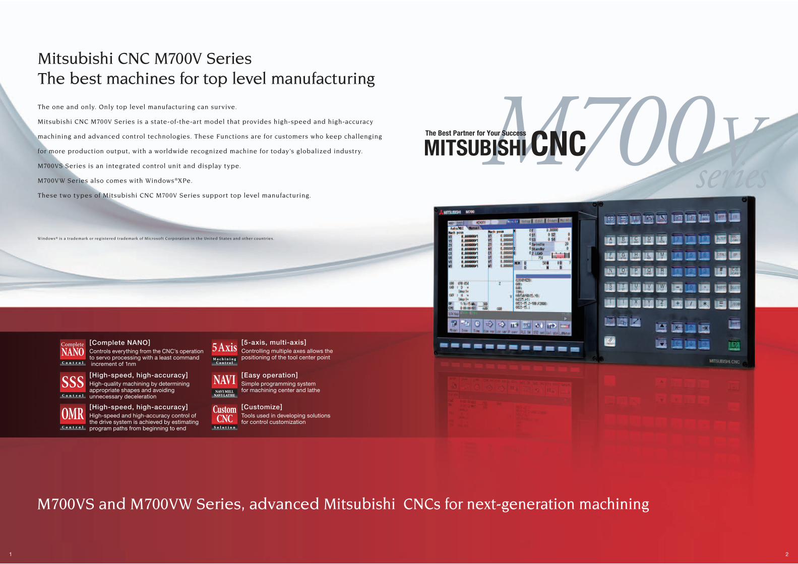
The Best Partner for Your Success
MITSUBISHI CNCM700V Series
BN
P-A1210-D
[ENG
]M
70
0V
Se
ries (E
NG
LISH
)
K-K02-8-C8220-D NA1110 Printed in Japan (MDOC)
Revised publication, effective Oct. 2011.Superseding publication of K-K02-8-C8220-C Oct. 2010.
Specifications are subject to change without notice.
BNP-A1210-D[ENG](ENGLISH)
1 2
seriesM700VThe Best Partner for Your Success
MITSUBISHI CNCThe one and only. Only top level manufacturing can survive.
Mitsubishi CNC M700V Series is a state-of-the-art model that provides high-speed and high-accuracy
machining and advanced control technologies. These Functions are for customers who keep challenging
for more production output, with a worldwide recognized machine for today’s globalized industry.
M700VS Series is an integrated control unit and display type.
M700VW Series also comes with Windows®XPe.
These two types of Mitsubishi CNC M700V Series support top level manufacturing.
Windows® is a trademark or registered trademark of Microsof t Corporation in the United States and other countr ies.
Mitsubishi CNC M700V Series The best machines for top level manufacturing
M700VS and M700VW Series, advanced Mitsubishi CNCs for next-generation machining
[High-speed, high-accuracy]High-quality machining by determining appropriate shapes and avoiding unnecessary deceleration
[High-speed, high-accuracy]High-speed and high-accuracy control of the drive system is achieved by estimating program paths from beginning to end
[Easy operation]Simple programming system for machining center and lathe
[Customize]Tools used in developing solutions for control customization
[Complete NANO]Controls everything from the CNC’s operation to servo processing with a least command increment of 1nm
[5-axis, multi-axis]Controlling multiple axes allows the positioning of the tool center point
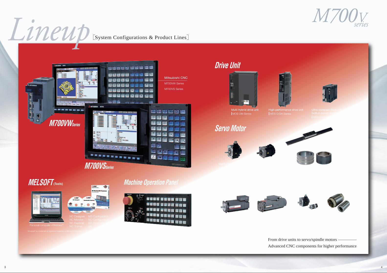
From drive units to servo/spindle motors Advanced CNC components for higher performance
NC DesignerNC MonitorNC ExplorerNC Trainer
MS ConfiguratorNC Configurator2GX Developeretc.
(Tools)
Mitsubishi CNC
M700VW Series
M700VS Series
3 4
System Configurations & Product Lines
Windows® is a trademark or registered trademark of Microsoft Corporation in the United States and other countries.
Personal computer+Windows®
M700VWSeries
Drive Unit
Servo Motor
Spindle Motor
M700VSSeries
seriesM700V
MELSOFT Machine Operation Panel
High-performance drive unit MDS-D/DH Series
Multi-hybrid drive unit MDS-DM Series
Ultra-compact drive unit with built-in power supply MDS-D-SVJ3/SPJ3 Series
Low-inertia motor HF-KP Series
Medium-inertia motor HF Series
Direct drive servo motor TM-RB Series
Linear servo motor LM-F Series
High-performance spindle motor SJ-D Series SJ-V Series
Low-inertia and high-speed spindle motor SJ-VL Series SJ-VLS Series
Tool spindle motor HF-KP Series HF-SP Series
Built-in spindle motor
seriesM700V
5 6
TechnologiesB a s i c P e r f o r m a n c e a n d F u n c t i o n s
For higher speed and higher accuracy
Bringing the complete nano world closer to you
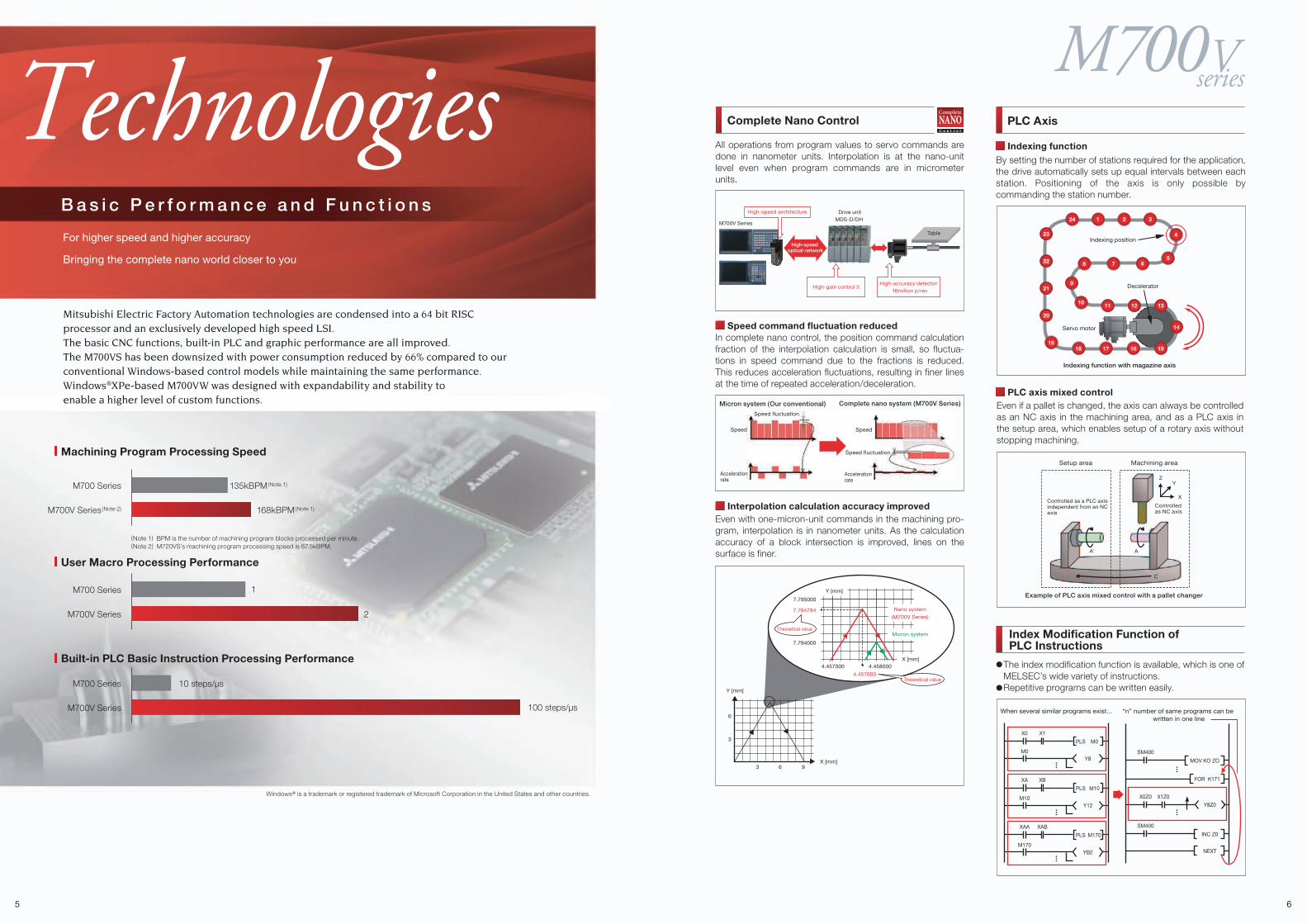
(Note 1) BPM is the number of machining program blocks processed per minute.(Note 2) M720VS’s machining program processing speed is 67.5kBPM.
M700V Series(Note 2) 168kBPM(Note 1)
M700 Series 135kBPM(Note 1)
Machining Program Processing Speed
M700V Series 2
1M700 Series
User Macro Processing Performance
M700V Series
M700 Series
Built-in PLC Basic Instruction Processing Performance
Windows® is a trademark or registered trademark of Microsoft Corporation in the United States and other countries.
All operations from program values to servo commands are done in nanometer units. Interpolation is at the nano-unit level even when program commands are in micrometer units.
Speed command fluctuation reducedIn complete nano control, the position command calculation fraction of the interpolation calculation is small, so fluctua-tions in speed command due to the fractions is reduced. This reduces acceleration fluctuations, resulting in finer lines at the time of repeated acceleration/deceleration.
Interpolation calculation accuracy improvedEven with one-micron-unit commands in the machining pro-gram, interpolation is in nanometer units. As the calculation accuracy of a block intersection is improved, lines on the surface is finer.
By setting the number of stations required for the application, the drive automatically sets up equal intervals between each station. Positioning of the axis is only possible by commanding the station number.
Even if a pallet is changed, the axis can always be controlled as an NC axis in the machining area, and as a PLC axis in the setup area, which enables setup of a rotary axis without stopping machining.
PLC Axis
Index Modification Function ofPLC Instructions
Complete Nano Control
Complete nano system (M700V Series)Micron system (Our conventional)
SpeedSpeed
Accelerationrate
Accelerationrate
Speed fluctuation
Speed fluctuation
Y [mm]
X [mm]
6
3
3 6 9
Nano system
(M700V Series)
Micron system
Y [mm]
X [mm]4.4580004.457000
4.457693
7.794784
7.795000
7.794000
Theoretical value
Theoretical value
PLC axis mixed control
Indexing function
Indexing function with magazine axis
Decelerator
17 16 15
131211
14
Indexing position23
22
21
20
1918
8 7 65
4
32124
10
9
Servo motor
The index modification function is available, which is one of MELSEC’s wide variety of instructions.Repetitive programs can be written easily.
X0
M0
X1
PLS M0
Y8
XA
M10
XB
PLS M10
Y12
XAA
M170
XAB
PLS M170
YB2
X0Z0
SM400
X1Z0
Y8Z0
FOR K171
NEXT
INC Z0
SM400
MOV KO ZO
Mitsubishi Electric Factory Automation technologies are condensed into a 64 bit RISC processor and an exclusively developed high speed LSI.The basic CNC functions, built-in PLC and graphic performance are all improved. The M700VS has been downsized with power consumption reduced by 66% compared to our conventional Windows-based control models while maintaining the same performance.Windows®XPe-based M700VW was designed with expandability and stability to enable a higher level of custom functions.
Example of PLC axis mixed control with a pallet changer
C
Controlled as a PLC axis independent from an NC axis
Controlled as NC axis
ZY
X
Setup area Machining area
AA’
M700V Series
Drive unitMDS-D/DH
High-gain control�IIHigh-accuracy detector:�
16million p/rev
High-speed architecture
Table
High-speed optical network
10 steps/µs
100 steps/µs When several similar programs exist... “n” number of same programs can be written in one line
seriesM700V
7 8
TechnologiesS u p p o r t i n g M a c h i n e To o l A c c u r a c y I m p r o v e m e n t
Calculated control (OMR control) of the drive system based on the machine model realizes
optimum machine operation
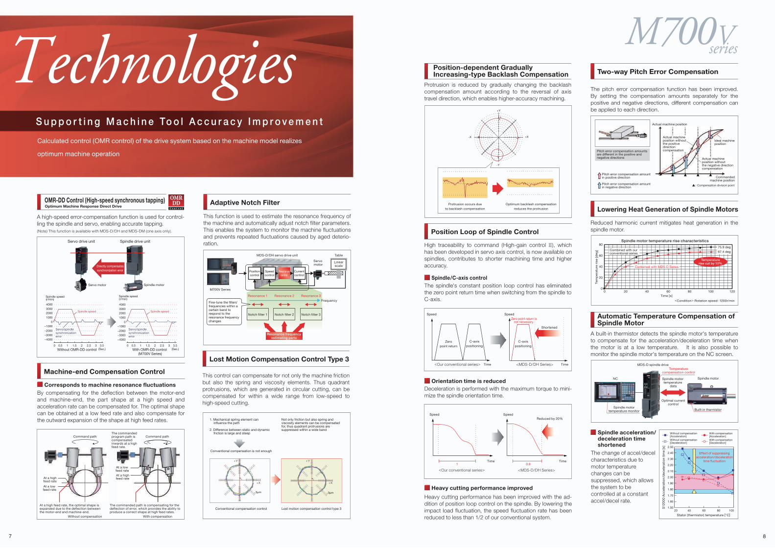
A high-speed error-compensation function is used for control-ling the spindle and servo, enabling accurate tapping.(Note) This function is available with MDS-D/DH and MDS-DM (one axis only).
OMR-DD Control (High-speed synchronous tapping)
Machine-end Compensation Control
Corresponds to machine resonance fluctuationsBy compensating for the deflection between the motor-end and machine-end, the part shape at a high speed and acceleration rate can be compensated for. The optimal shape can be obtained at a low feed rate and also compensate for the outward expansion of the shape at high feed rates.
Position Loop of Spindle Control
Heavy cutting performance improved
Heavy cutting performance has been improved with the ad-dition of position loop control on the spindle. By lowering the impact load fluctuation, the speed fluctuation rate has been reduced to less than 1/2 of our conventional system.
Time
Speed Speed
Time
Reduced by 20%
1 0.8
Orientation time is reducedDeceleration is performed with the maximum torque to mini-mize the spindle orientation time.
The spindle's constant position loop control has eliminated the zero point return time when switching from the spindle to C-axis.
Spindle/C-axis control
High traceability to command (High-gain control II), which has been developed in servo axis control, is now available on spindles, contributes to shorter machining time and higher accuracy.
At a high feed rate, the optimal shape is expanded due to the deflection between the motor-end and machine-end.
At a high feed rate
Command path
Without compensation
At a low feed rate
The commanded path is compensating for the deflection of error, which provides the ability to produce a correct shape at high feed rates.
Command path
With compensation
Lowering Heat Generation of Spindle Motors
Reduced harmonic current mitigates heat generation in the spindle motor.
Time [s]
<Condition> Rotation speed: 1200r/min
00
20
20
40
40
60
60
80
80
100 120
Spindle motor temperature rise characteristics
Combined with MDS-D Series
Combined with our conventional series
75.9 deg
67.4 deg
Temperaturerise cut by 10%
Tem
pe
ratu
re r
ise
[de
g]
The commanded program path is compensated inwards at a high feed rate.
Optimum Machine Response Direct Drive
At a low feed rate
At a high feed rate
Protrusion occurs due
to backlash compensation
Optimum backlash compensation
reduces the protrusion
Protrusion is reduced by gradually changing the backlash compensation amount according to the reversal of axis travel direction, which enables higher-accuracy machining.
Position-dependent GraduallyIncreasing-type Backlash Compensation
Adaptive Notch Filter
This function is used to estimate the resonance frequency of the machine and automatically adjust notch filter parameters. This enables the system to monitor the machine fluctuations and prevents repeated fluctuations caused by aged deterio-ration.
M700V Series
MDS-D/DH servo drive unit
Servo motor
Resonancecontrol
FrequencyResonance 1
Notch filter 1
Resonance 2
Notch filter 2
Resonance 3
Notch filter 3
Resonance frequencyestimating parts
Fine-tune the filters' frequencies within a certain band to respond to the resonance frequency changes
Table
Linearscale
Positioncontrol
Speedcontrol
Currentcontrol
Spindle drive unit
Directly compensatessynchronization error
Spindle motorServo motor
Servo drive unit
Time Time
C-axispositioning
Zeropoint return
C-axispositioning
SpeedSpeed
Shortened
Zero point return isnot necessary.
<Our conventional series> <MDS-D/DH Series>
<Our conventional series> <MDS-D/DH Series>
Spindle acceleration/deceleration time shortened
The change of accel/decel characteristics due to motor temperature changes can be suppressed, which allows the system to be controlled at a constant accel/decel rate.
1.50
1.60
1.70
1.80
1.90
2.00
2.10
2.20
2.30
2.40
2.50
100
A built-in thermistor detects the spindle motor's temperature to compensate for the acceleration/deceleration time when the motor is at a low temperature. It is also possible to monitor the spindle motor's temperature on the NC screen.
Automatic Temperature Compensation ofSpindle Motor
20 40 60 80
Stator (thermistor) temperature [°C]
Effect of suppressingacceleration/deceleration
time fluctuation
With compensation[Acceleration]With compensation[Deceleration]
Without compensation[Acceleration]Without compensation[Deceleration]
S12
00
0 A
ccel
erat
ion
/dec
eler
atio
n tim
e [s
]
NC
MDS-D spindle drive
Spindle motortemperature monitor
Temperaturecompensation control
Spindle motor temperature
data
Optimal currentcontrol
Spindle motor
Built-in thermistor
−4000
−3000
0 0.5 1 1.5 2 2.5 3 3.5
Without OMR-DD control
Servo/spindlesynchronization error
Spindle speed
Servo/spindlesynchronization error
Spindle speed
With OMR-DD control (M700V Series)
−2000
−1000
1000
20003000
4000
0
−4000
−3000
0 0.5 1 1.5 2 2.5 3 3.5
−2000
−1000
1000
20003000
4000
0
(Sec.) (Sec.)
Spindle speed(r/min)
Spindle speed(r/min)
This control can compensate for not only the machine friction but also the spring and viscosity elements. Thus quadrant protrusions, which are generated in circular cutting, can be compensated for within a wide range from low-speed to high-speed cutting.
Lost Motion Compensation Control Type 3
Conventional compensation control
Conventional compensation is not enough
Lost motion compensation control type 3
+Y
+X
+Y
+X
3µm 3µm
+Y
+X-X
-Y
Two-way Pitch Error Compensation
The pitch error compensation function has been improved. By setting the compensation amounts separately for the positive and negative directions, different compensation can be applied to each direction.
Pitch error compensation amounts are different in the positive and negative directions
Pitch error compensation amount in positive direction
Pitch error compensation amount in negative direction
Actual machine position
Actual machine position without the positive direction compensation
Ideal machineposition
Actual machine position without the negative direction compensation
Commandedmachine position
: Compensation division point
1. Mechanical spring element can influence the path
2. Difference between static and dynamic friction is large and steep
Not only friction but also spring and viscosity elements can be compensated for, thus quadrant protrusions are suppressed within a wide band
seriesM700V
9 10
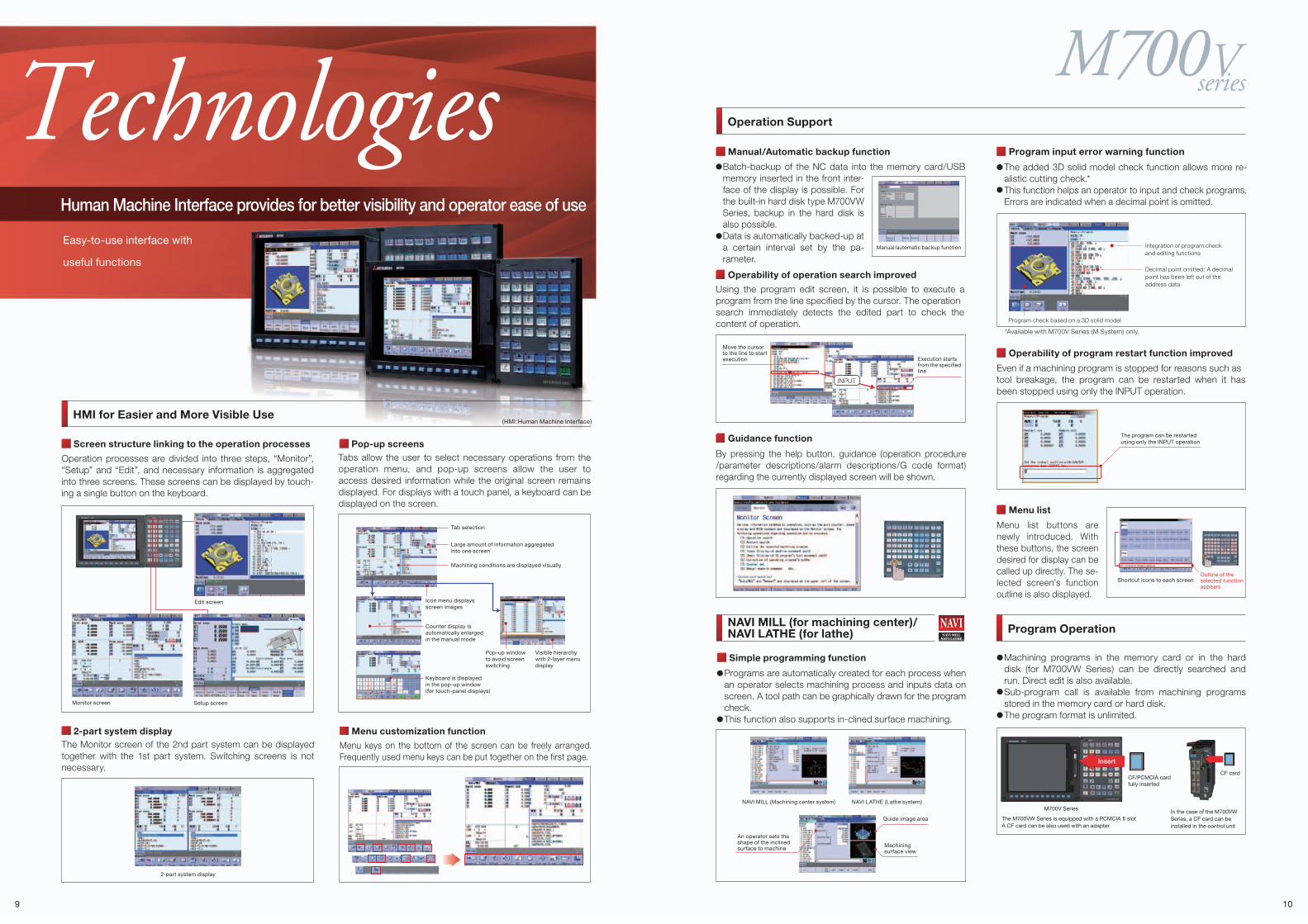
TechnologiesHuman Machine Interface provides for better visibility and operator ease of use
Easy-to-use interface with
useful functions
Screen structure linking to the operation processes Pop-up screens
Machining programs in the memory card or in the hard disk (for M700VW Series) can be directly searched and run. Direct edit is also available.Sub-program call is available from machining programs stored in the memory card or hard disk.The program format is unlimited.
Simple programming function
Operation Support
HMI for Easier and More Visible Use
Tabs allow the user to select necessary operations from the operation menu, and pop-up screens allow the user to access desired information while the original screen remains displayed. For displays with a touch panel, a keyboard can be displayed on the screen.
Operation processes are divided into three steps, “Monitor”, “Setup” and “Edit”, and necessary information is aggregated into three screens. These screens can be displayed by touch-ing a single button on the keyboard.
Menu customization function
Menu keys on the bottom of the screen can be freely arranged. Frequently used menu keys can be put together on the first page.
Operability of program restart function improved
Even if a machining program is stopped for reasons such astool breakage, the program can be restarted when it has been stopped using only the INPUT operation.
Manual/Automatic backup function
Batch-backup of the NC data into the memory card/USB memory inserted in the front inter-face of the display is possible. For the built-in hard disk type M700VW Series, backup in the hard disk is also possible.Data is automatically backed-up at a certain interval set by the pa-rameter.
Manual/automatic backup function
NAVI MILL (for machining center)/NAVI LATHE (for lathe)
Operability of operation search improved
Using the program edit screen, it is possible to execute a program from the line specified by the cursor. The operationsearch immediately detects the edited part to check the content of operation.
Edit screen
Setup screenMonitor screen
The program can be restartedusing only the INPUT operation
2-part system displayThe Monitor screen of the 2nd part system can be displayed together with the 1st part system. Switching screens is not necessary.
Program Operation
Programs are automatically created for each process when an operator selects machining process and inputs data on screen. A tool path can be graphically drawn for the program check. This function also supports in-clined surface machining.
Menu list
Shortcut icons to each screen
Menu list buttons are newly introduced. With these buttons, the screen desired for display can be called up directly. The se-lected screen’s function outline is also displayed.
Outline of the selected function appears
2-part system display
An operator sets the shape of the inclined surface to machine Machining
surface view
Guide image area
NAVI MILL (Machining center system) NAVI LATHE (Lathe system)
Guidance function
By pressing the help button, guidance (operation procedure /parameter descriptions/alarm descriptions/G code format) regarding the currently displayed screen will be shown.
Tab selection
Large amount of information aggregatedinto one screen
Machining conditions are displayed visually
Icon menu displaysscreen images
Counter display is automatically enlarged in the manual mode
Pop-up window to avoid screen switching
Keyboard is displayed in the pop-up window(for touch-panel displays)
Visible hierarchy with 2-layer menu display
INPUT
Move the cursorto the line to start execution Execution starts
from the specifiedline
*Available with M700V Series (M System) only.
In the case of the M700VW Series, a CF card can be installed in the control unit
M700V Series
Insert
CF cardCF/PCMCIA cardfully inserted
The M700VW Series is equipped with a PCMCIA II slotA CF card can be also used with an adapter
(HMI:Human Machine Interface)
Program input error warning function
Program check based on a 3D solid model
Decimal point omitted: A decimal point has been left out of the address data
Integration of program check and editing functions
The added 3D solid model check function allows more re-alistic cutting check.*This function helps an operator to input and check programs. Errors are indicated when a decimal point is omitted.
seriesM700VTechnologies
11 12
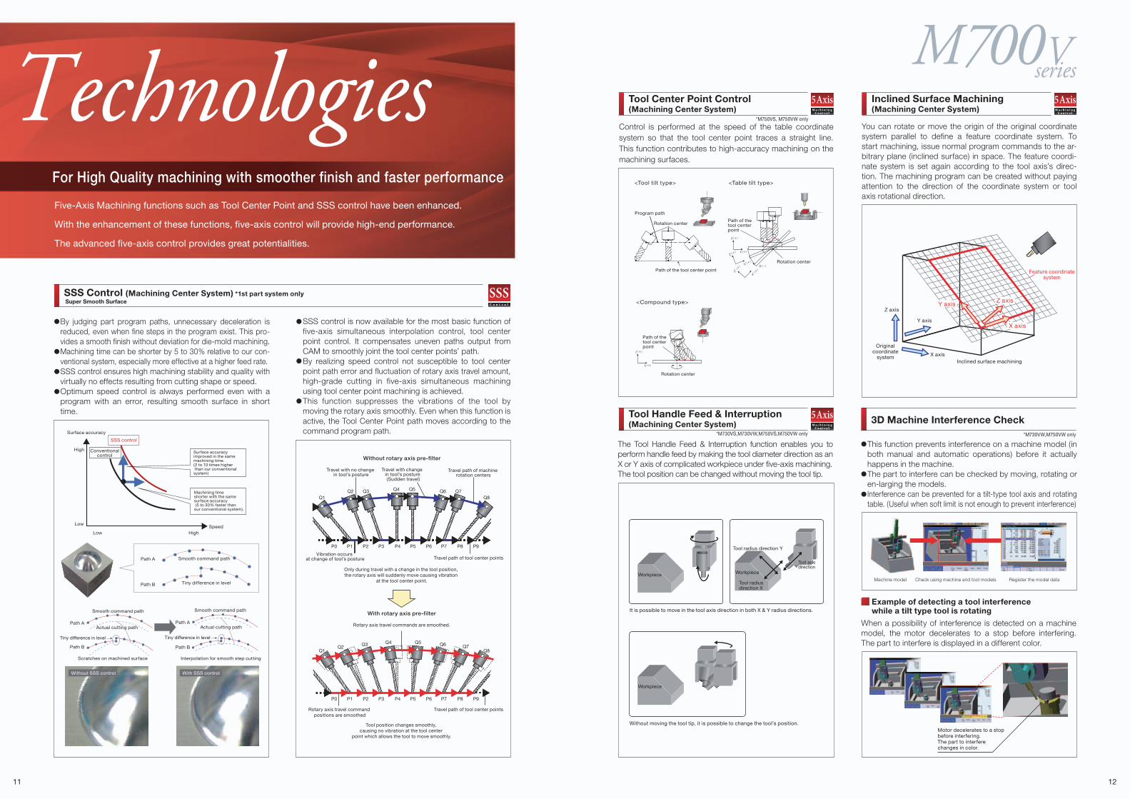
For High Quality machining with smoother finish and faster performance
Five-Axis Machining functions such as Tool Center Point and SSS control have been enhanced.
With the enhancement of these functions, five-axis control will provide high-end performance.
The advanced five-axis control provides great potentialities.
By judging part program paths, unnecessary deceleration is reduced, even when fine steps in the program exist. This pro-vides a smooth finish without deviation for die-mold machining.Machining time can be shorter by 5 to 30% relative to our con-ventional system, especially more effective at a higher feed rate.SSS control ensures high machining stability and quality with virtually no effects resulting from cutting shape or speed.Optimum speed control is always performed even with a program with an error, resulting smooth surface in short time.
SSS control is now available for the most basic function of five-axis simultaneous interpolation control, tool center point control. It compensates uneven paths output from CAM to smoothly joint the tool center points’ path.By realizing speed control not susceptible to tool center point path error and fluctuation of rotary axis travel amount, high-grade cutting in five-axis simultaneous machining using tool center point machining is achieved.This function suppresses the vibrations of the tool by moving the rotary axis smoothly. Even when this function is active, the Tool Center Point path moves according to the command program path.
The Tool Handle Feed & Interruption function enables you to perform handle feed by making the tool diameter direction as an X or Y axis of complicated workpiece under five-axis machining.The tool position can be changed without moving the tool tip.
Control is performed at the speed of the table coordinate system so that the tool center point traces a straight line. This function contributes to high-accuracy machining on the machining surfaces.
You can rotate or move the origin of the original coordinate system parallel to define a feature coordinate system. To start machining, issue normal program commands to the ar-bitrary plane (inclined surface) in space. The feature coordi-nate system is set again according to the tool axis’s direc-tion. The machining program can be created without paying attention to the direction of the coordinate system or tool axis rotational direction.
This function prevents interference on a machine model (in both manual and automatic operations) before it actually happens in the machine.The part to interfere can be checked by moving, rotating or en-larging the models.Interference can be prevented for a tilt-type tool axis and rotating table. (Useful when soft limit is not enough to prevent interference)
Example of detecting a tool interference while a tilt type tool is rotating
When a possibility of interference is detected on a machine model, the motor decelerates to a stop before interfering. The part to interfere is displayed in a different color.
SSS Control (Machining Center System) *1st part system onlySuper Smooth Surface
Tool Center Point Control(Machining Center System)
3D Machine Interference CheckTool Handle Feed & Interruption(Machining Center System)
Inclined Surface Machining(Machining Center System)
Without rotary axis pre-filter
With rotary axis pre-filter
Only during travel with a change in the tool position, the rotary axis will suddenly move causing vibration
at the tool center point.
Rotary axis travel commands are smoothed.
Tool position changes smoothly, causing no vibration at the tool center
point which allows the tool to move smoothly.
Travel with no change in tool’s posture
Travel with change in tool’s posture (Sudden travel)
Vibration occurs at change of tool’s posture Travel path of tool center points
Rotary axis travel command positions are smoothed
Travel path of tool center points
Travel path of machine rotation centers
Without moving the tool tip, it is possible to change the tool’s position.
Originalcoordinate
system
Z axis
Y axis
X axisInclined surface machining
Feature coordinatesystem
Surface accuracy improved in the same machining time. (2 to 10 times higher than our conventional system)
Conventionalcontrol
Machining time shorter with the same surface accuracy (5 to 30% faster than our conventional system).
SSS control
Surface accuracy
Speed
High
Low
Low High
Path A Smooth command path
Tiny difference in levelPath B
With SSS controlWithout SSS control
Q1
P0 P1 P2 P3 P4 P5 P6 P7 P8 P9
P0 P1 P2 P3 P4 P5 P6 P7 P8 P9
Q8Q2 Q3 Q6 Q7Q4 Q5
Q1 Q8Q2 Q3 Q6 Q7
Q4 Q5
<Tool tilt type> <Table tilt type>
<Compound type>
Rotation center
Program path
Rotation center
Path of the tool center point
Rotation center
Path of the tool center point
Path of the tool center point
Machine model Check using machine and tool models Register the model data
Motor decelerates to a stop before interfering. The part to interfere changes in color.
Y axis Z axis
X axis
Interpolation for smooth step cuttingScratches on machined surface
Smooth command path Smooth command path
Actual cutting path Actual cutting pathPath A
Path B
Path A
Path B
Tiny difference in level Tiny difference in level
*M750VS, M750VW only
*M730VW,M750VW only*M730VS,M730VW,M750VS,M750VW only
Workpiece
It is possible to move in the tool axis direction in both X & Y radius directions.
Workpiece
Tool radius direction X
Tool radius direction Y
Tool axis direction
Workpiece
seriesM700V
13 14
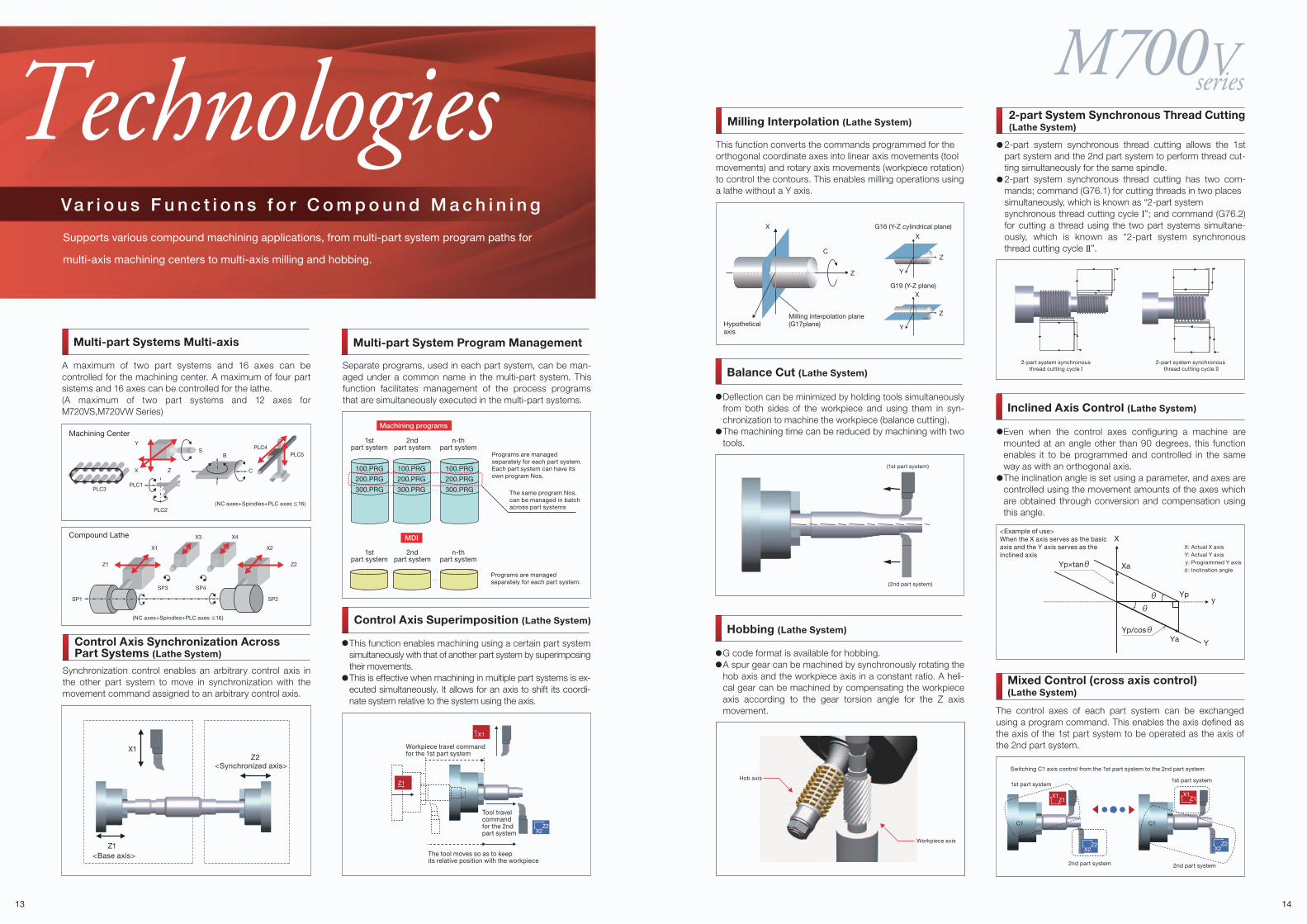
TechnologiesVa r i o u s F u n c t i o n s f o r C o m p o u n d M a c h i n i n g
Supports various compound machining applications, from multi-part system program paths for
multi-axis machining centers to multi-axis milling and hobbing.
G code format is available for hobbing.A spur gear can be machined by synchronously rotating the hob axis and the workpiece axis in a constant ratio. A heli-cal gear can be machined by compensating the workpiece axis according to the gear torsion angle for the Z axis movement.
2-part system synchronousthread cutting cycle I
2-part system synchronous thread cutting cycle II
<Example of use> When the X axis serves as the basicaxis and the Y axis serves as theinclined axis
Yp/cos
Yp×tan
X
Y
y
Xa
Yp
Ya
X: Actual X axisY: Actual Y axis y: Programmed Y axis
: Inclination angle
Balance Cut (Lathe System)
Hobbing (Lathe System)
2-part System Synchronous Thread Cutting(Lathe System)
Inclined Axis Control (Lathe System)
Separate programs, used in each part system, can be man-aged under a common name in the multi-part system. This function facilitates management of the process programs that are simultaneously executed in the multi-part systems.
A maximum of two part systems and 16 axes can be controlled for the machining center. A maximum of four part sistems and 16 axes can be controlled for the lathe.(A maximum of two part systems and 12 axes for M720VS,M720VW Series)
Multi-part System Program Management
The control axes of each part system can be exchanged using a program command. This enables the axis defined as the axis of the 1st part system to be operated as the axis of the 2nd part system.
Mixed Control (cross axis control)(Lathe System)
Milling Interpolation (Lathe System)
This function converts the commands programmed for theorthogonal coordinate axes into linear axis movements (toolmovements) and rotary axis movements (workpiece rotation) to control the contours. This enables milling operations using a lathe without a Y axis.
Multi-part Systems Multi-axis
Hob axis
Workpiece axis
Machining Center
Compound Lathe
PLC3PLC1
BS PLC4
PLC5
C
PLC2
X Z
Y
SP1 SP2
SP3 SP4
Z1 Z2
X1 X2
X3 X4
1stpart system
2ndpart system
100.PRG
200.PRG
300.PRG
100.PRG
200.PRG
300.PRG
100.PRG
200.PRG
300.PRG
n-thpart system
1stpart system
Workpiece travel commandfor the 1st part system
Tool travel commandfor the 2nd part system
The tool moves so as to keep its relative position with the workpiece
2ndpart system
n-thpart system
Programs are managed separately for each part system.Each part system can have itsown program Nos.
Programs are managed separately for each part system.
The same program Nos. can be managed in batchacross part systems
Machining programs
MDI
X1Z2
<Synchronized axis>
Z1 <Base axis>
Synchronization control enables an arbitrary control axis in the other part system to move in synchronization with the movement command assigned to an arbitrary control axis.
Control Axis Synchronization AcrossPart Systems (Lathe System)
Control Axis Superimposition (Lathe System)
2-part system synchronous thread cutting allows the 1st part system and the 2nd part system to perform thread cut-ting simultaneously for the same spindle.2-part system synchronous thread cutting has two com-mands; command (G76.1) for cutting threads in two placessimultaneously, which is known as “2-part systemsynchronous thread cutting cycle I”; and command (G76.2) for cutting a thread using the two part systems simultane-ously, which is known as “2-part system synchronous thread cutting cycle II”.
Even when the control axes configuring a machine are mounted at an angle other than 90 degrees, this function enables it to be programmed and controlled in the same way as with an orthogonal axis.The inclination angle is set using a parameter, and axes are controlled using the movement amounts of the axes which are obtained through conversion and compensation using this angle.
(1st part system)
(2nd part system)
X1Z1
X2Z2
C1C1
X1Z1
X2Z2
Switching C1 axis control from the 1st part system to the 2nd part system
1st part system1st part system
2nd part system2nd part system
X1
X2Z2
Z1
Deflection can be minimized by holding tools simultaneously from both sides of the workpiece and using them in syn-chronization to machine the workpiece (balance cutting).The machining time can be reduced by machining with two tools.
This function enables machining using a certain part system simultaneously with that of another part system by superimposing their movements.This is effective when machining in multiple part systems is ex-ecuted simultaneously. It allows for an axis to shift its coordi-nate system relative to the system using the axis.
X
X
C
Z
Z
Y
X
Z
YHypothetical axis
Milling interpolation plane(G17plane)
G16 (Y-Z cylindrical plane)
G19 (Y-Z plane)
seriesM700V
15 16
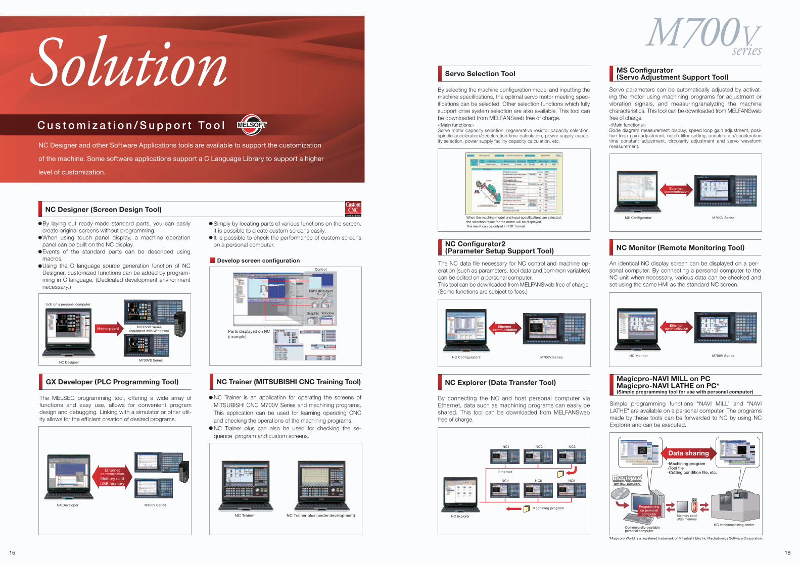
SolutionC u s t o m i z a t i o n / S u p p o r t To o l
NC Designer and other Software Applications tools are available to support the customization
of the machine. Some software applications support a C Language Library to support a higher
level of customization.
Simply by locating parts of various functions on the screen, it is possible to create custom screens easily.It is possible to check the performance of custom screens on a personal computer.
NC Designer (Screen Design Tool)
Parts displayed on NC(example)
Develop screen configuration
Edit on a personal computer
NC Designer
By laying out ready-made standard parts, you can easily create original screens without programming.When using touch panel display, a machine operation panel can be built on the NC display.Events of the standard parts can be described using macros.Using the C language source generation function of NC Designer, customized functions can be added by program-ming in C language. (Dedicated development environment necessary.)
The MELSEC programming tool, offering a wide array of functions and easy use, allows for convenient program design and debugging. Linking with a simulator or other util-ity allows for the efficient creation of desired programs.
GX Developer (PLC Programming Tool) NC Trainer (MITSUBISHI CNC Training Tool)
M700V SeriesGX Developer
M700VS Series
M700VW Series(equipped with Windows)
Control
Parts displayed
WindowGraphic
Servo Selection Tool
When the machine model and input specifications are selected,the selection result for the motor will be displayed.The result can be output in PDF format.
By selecting the machine configuration model and inputting the machine specifications, the optimal servo motor meeting spec-ifications can be selected. Other selection functions which fully support drive system selection are also available. This tool can be downloaded from MELFANSweb free of charge.<Main functions>Servo motor capacity selection, regenerative resistor capacity selection, spindle acceleration/deceleration time calculation, power supply capac-ity selection, power supply facility capacity calculation, etc.
An identical NC display screen can be displayed on a per-sonal computer. By connecting a personal computer to the NC unit when necessary, various data can be checked and set using the same HMI as the standard NC screen.
NC Monitor (Remote Monitoring Tool)
NC Monitor M700V Series
Ethernet communication
The NC data file necessary for NC control and machine op-eration (such as parameters, tool data and common variables) can be edited on a personal computer. This tool can be downloaded from MELFANSweb free of charge.(Some functions are subject to fees.)
NC Configurator2(Parameter Setup Support Tool)
NC Configurator2 M700V Series
By connecting the NC and host personal computer via Ethernet, data such as machining programs can easily be shared. This tool can be downloaded from MELFANSweb free of charge.
NC Explorer (Data Transfer Tool)
NC1 NC2 NC3
NC4
Ethernet
NC5 NC6
Machining program
NC Explorer
Servo parameters can be automatically adjusted by activat-ing the motor using machining programs for adjustment or vibration signals, and measuring/analyzing the machine characteristics. This tool can be downloaded from MELFANSweb free of charge.<Main functions>Bode diagram measurement display, speed loop gain adjustment, posi-tion loop gain adjustment, notch filter setting, acceleration/deceleration time constant adjustment, circularity adjustment and servo waveform measurement.
MS Configurator(Servo Adjustment Support Tool)
MS Configurator M700V Series
Simple programming functions "NAVI MILL" and "NAVI LATHE" are available on a personal computer. The programs made by these tools can be forwarded to NC by using NC Explorer and can be executed.
Magicpro-NAVI MILL on PCMagicpro-NAVI LATHE on PC*(Simple programming tool for use with personal computer)
*
Commercially-availablepersonal computer
Memory cardUSB memory
NC lathe/machining center
*Magicpro World is a registered trademark of Mitsubishi Electric Mechatronics Software Corporation.
-Machining program-Tool file-Cutting condition file, etc.
Programmingon personalcomputer
Data sharing
Ethernetcommunication
Memory cardUSB memory
Ethernet communication
Ethernet communication
NC Trainer NC Trainer plus�(under development)
NC Trainer is an application for operating the screens of MITSUBISHI CNC M700V Series and machining programs. This application can be used for learning operating CNC and checking the operations of the machining programs. NC Trainer plus can also be used for checking the se-quence program and custom screens.
Memory card
17 18
Main Specif icat ions
Spindle Motors
Servo Motors
Displays & Keyboards
Dr ive Units
M730VW
6
AvailableAvailableAvailable
1nm
128,000 steps
M720VW128
44
6
0.1µm
1616
66
8
1nm
16166
66
84
1nm
4 4
M730VW
46
2AvailableAvailableAvailable
1nm
128,000 steps
M750VW
8
M720VW12124
44
62
0.1µm
2,000kB(5,120m)
M750VW
8
1616
6
8
1nm
16166
6
84
1nm
4 4
M720VS128
4
6
0.1µm
M730VS
46
2
Available
1nm
128,000 steps
M750VS
8
M720VS12124
4
62
0.1µm
M730VS
6
Available
1nm
128,000 steps
M750VS
8
FCU7-KB921
FCU7-KB926
140
260
140
140
[mm]
[mm]
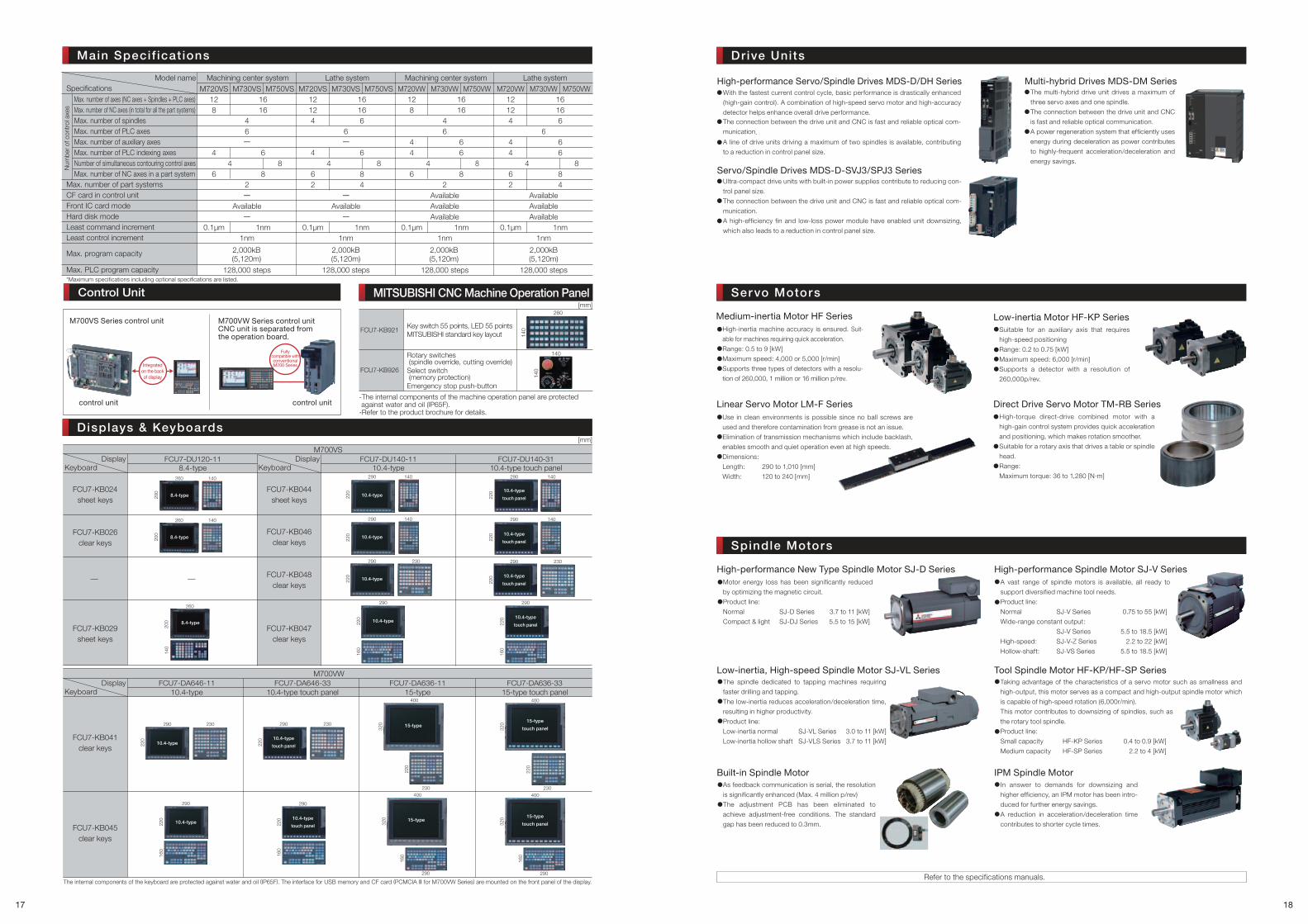
Max. number of axes (NC axes + Spindles + PLC axes)Max. number of NC axes (in total for all the part systems)Max. number of spindlesMax. number of PLC axesMax. number of auxiliary axesMax. number of PLC indexing axesNumber of simultaneous contouring control axesMax. number of NC axes in a part system
Max. number of part systemsCF card in control unitFront IC card mode Hard disk mode Least command increment Least control increment
Max. PLC program capacity
Machining center system Machining center systemLathe system Lathe systemModel nameSpecifications
Num
ber
of c
ontr
ol a
xes
Max. program capacity
*Maximum specifications including optional specifications are listed.
Key switch 55 points, LED 55 pointsMITSUBISHI standard key layout
Rotary switches (spindle override, cutting override)Select switch (memory protection)Emergency stop push-button
-The internal components of the machine operation panel are protected against water and oil (IP65F).
-Refer to the product brochure for details.
MITSUBISHI CNC Machine Operation Panel
High-performance Servo/Spindle Drives MDS-D/DH SeriesThe multi-hybrid drive unit drives a maximum of
three servo axes and one spindle.
The connection between the drive unit and CNC
is fast and reliable optical communication.
A power regeneration system that efficiently uses
energy during deceleration as power contributes
to highly-frequent acceleration/deceleration and
energy savings.
Multi-hybrid Drives MDS-DM Series
Ultra-compact drive units with built-in power supplies contribute to reducing con-
trol panel size.
The connection between the drive unit and CNC is fast and reliable optical com-
munication.
A high-efficiency fin and low-loss power module have enabled unit downsizing,
which also leads to a reduction in control panel size.
Servo/Spindle Drives MDS-D-SVJ3/SPJ3 Series
With the fastest current control cycle, basic performance is drastically enhanced
(high-gain control). A combination of high-speed servo motor and high-accuracy
detector helps enhance overall drive performance.The connection between the drive unit and CNC is fast and reliable optical com-
munication.
A line of drive units driving a maximum of two spindles is available, contributing
to a reduction in control panel size.
High-inertia machine accuracy is ensured. Suit-
able for machines requiring quick acceleration.
Range: 0.5 to 9 [kW]
Maximum speed: 4,000 or 5,000 [r/min]
Supports three types of detectors with a resolu-
tion of 260,000, 1 million or 16 million p/rev.
Suitable for an auxiliary axis that requires
high-speed positioning
Range: 0.2 to 0.75 [kW]
Maximum speed: 6,000 [r/min]
Supports a detector with a resolution of
260,000p/rev.
Use in clean environments is possible since no ball screws are
used and therefore contamination from grease is not an issue.
Elimination of transmission mechanisms which include backlash,
enables smooth and quiet operation even at high speeds.
Dimensions:
Length: 290 to 1,010 [mm]
Width: 120 to 240 [mm]
High-torque direct-drive combined motor with a
high-gain control system provides quick acceleration
and positioning, which makes rotation smoother.
Suitable for a rotary axis that drives a table or spindle
head.
Range:
Maximum torque: 36 to 1,280 [N·m]
Medium-inertia Motor HF Series
Linear Servo Motor LM-F Series Direct Drive Servo Motor TM-RB Series
Low-inertia Motor HF-KP Series
Motor energy loss has been significantly reduced
by optimizing the magnetic circuit.
Product line:
Normal SJ-D Series 3.7 to 11 [kW]
Compact & light SJ-DJ Series 5.5 to 15 [kW]
High-performance New Type Spindle Motor SJ-D SeriesA vast range of spindle motors is available, all ready to
support diversified machine tool needs.
Product line:
Normal SJ-V Series 0.75 to 55 [kW]
Wide-range constant output:
SJ-V Series 5.5 to 18.5 [kW]
High-speed: SJ-V-Z Series 2.2 to 22 [kW]
Hollow-shaft: SJ-VS Series 5.5 to 18.5 [kW]
High-performance Spindle Motor SJ-V Series
The spindle dedicated to tapping machines requiring
faster drilling and tapping.
The low-inertia reduces acceleration/deceleration time,
resulting in higher productivity.
Product line:
Low-inertia normal SJ-VL Series 3.0 to 11 [kW]
Low-inertia hollow shaft SJ-VLS Series 3.7 to 11 [kW]
Low-inertia, High-speed Spindle Motor SJ-VL SeriesTaking advantage of the characteristics of a servo motor such as smallness and
high-output, this motor serves as a compact and high-output spindle motor which
is capable of high-speed rotation (6,000r/min).
This motor contributes to downsizing of spindles, such as
the rotary tool spindle.
Product line:
Small capacity HF-KP Series 0.4 to 0.9 [kW]
Medium capacity HF-SP Series 2.2 to 4 [kW]
Tool Spindle Motor HF-KP/HF-SP Series
As feedback communication is serial, the resolution
is significantly enhanced (Max. 4 million p/rev)
The adjustment PCB has been eliminated to
achieve adjustment-free conditions. The standard
gap has been reduced to 0.3mm.
Built-in Spindle MotorIn answer to demands for downsizing and
higher efficiency, an IPM motor has been intro-
duced for further energy savings.
A reduction in acceleration/deceleration time
contributes to shorter cycle times.
IPM Spindle Motor
Refer to the specifications manuals.
FCU7-KB024sheet keys
FCU7-KB029sheet keys
FCU7-KB026clear keys
FCU7-KB044sheet keys
FCU7-KB047clear keys
FCU7-KB046clear keys
FCU7-KB048clear keys
FCU7-DU120-118.4-type
FCU7-DU140-1110.4-type
FCU7-DU140-3110.4-type touch panel
M700VS
FCU7-KB045clear keys
FCU7-KB041clear keys
FCU7-DA646-1110.4-type
FCU7-DA636-1115-type
FCU7-DA646-3310.4-type touch panel
FCU7-DA636-3315-type touch panel
M700VW
The internal components of the keyboard are protected against water and oil (IP65F). The interface for USB memory and CF card (PCMCIA II for M700VW Series) are mounted on the front panel of the display.
8.4-type
10.4-type
touch panel
10.4-type
touch panel
10.4-type
touch panel
10.4-type
touch panel
10.4-type
10.4-type
10.4-type
10.4-type
260 140
200
290 140
220
290 140
220
290 140
220
290 230
220
290
220
160
290 140
220
290 230
220
290
220
160
10.4-type
290
220
160
160
160
260 140
200
260
200
140
10.4-type
touch panel10.4-type
290 230
220
290 230
220
10.4-type
touch panel
290
220
400
230
320
400
230
320
220
220
15-type
400
290
160
290
320 15-type
15-type
touch panel
400
320 15-type
touch panel
KeyboardDisplay
KeyboardDisplay
KeyboardDisplay
——
8.4-type
8.4-type
Control Unit
M700VS Series control unit M700VW Series control unitCNC unit is separated from the operation board.
Fullycompatible withconventionalM700 SeriesIntegrated
on the backof display
control unit control unit
2,000kB(5,120m)
2,000kB(5,120m)
2,000kB(5,120m)

The Best Partner for Your Success
MITSUBISHI CNCM700V Series
BN
P-A1210-D
[ENG
]M
70
0V
Se
ries (E
NG
LISH
)
K-K02-8-C8220-D NA1109 Printed in Japan (MDOC)
Revised publication, effective Sep. 2011.Superseding publication of K-K02-8-C8220-C Oct. 2010.
Specifications are subject to change without notice.
BNP-A1210-D[ENG](ENGLISH)