Embed Size (px)
Citation preview

Exploring Network Traffic Generation in a Simulation Environment
by
Nishant Khanna
B.Tech(IT), Amity University, Rajasthan, 2013
A Project Submitted in Partial Fulfillment of the
Requirements for the Degree of
MASTER OF SCIENCE
in the Department of Computer Science
c© Nishant Khanna, 2017
University of Victoria
All rights reserved. This project may not be reproduced in whole or in part, by
photocopying or other means, without the permission of the author.

ii
Exploring Network Traffic Generation in a Simulation Environment
by
Nishant Khanna
B.Tech(IT), Amity University, Rajasthan, 2013
Supervisory Committee
Dr. Yvonne Coady, Supervisor
(Department of Computer Science)
Dr. Sudhakar Ganti, Departmental Member
(Department of Computer Science)

iii
Supervisory Committee
Dr. Yvonne Coady, Supervisor
(Department of Computer Science)
Dr. Sudhakar Ganti, Departmental Member
(Department of Computer Science)
ABSTRACT
Simulations have become a very effective approach for visualizing how data trans-
fer takes place in a network. But simulating network traffic in iCanCloud is a chal-
lenging process for students trying to learn how protocols work. This project proposes
an environment combining an implementation of TCP/IP using INET and iCanCloud
on top of OMNeT++ to simulate network traffic. Documenting the design of all the
created simulations provide rationale as to how network traffic is generated. Further-
more, this project shows how promising the proposed environment is for analyzing
network traffic. Evaluating and analyzing the created simulations provides potential
ideas for extending the proposed environment as a platform for learning in the future.

iv
Contents
Supervisory Committee ii
Abstract iii
Table of Contents iv
List of Tables vii
List of Figures viii
Acknowledgements xi
Dedication xii
1 Introduction 1
1.1 Structure of the report . . . . . . . . . . . . . . . . . . . . . . . . . . 1
2 Related Work 3
2.1 Simulation Platforms . . . . . . . . . . . . . . . . . . . . . . . . . . . 3
2.1.1 OMNeT++ . . . . . . . . . . . . . . . . . . . . . . . . . . . . 3
2.1.2 NS-2 . . . . . . . . . . . . . . . . . . . . . . . . . . . . . . . . 4
2.1.3 OPNET . . . . . . . . . . . . . . . . . . . . . . . . . . . . . . 4
2.2 Cloud Simulation Platforms . . . . . . . . . . . . . . . . . . . . . . . 5
2.2.1 iCanCloud . . . . . . . . . . . . . . . . . . . . . . . . . . . . . 5
2.2.2 CloudSim . . . . . . . . . . . . . . . . . . . . . . . . . . . . . 5
2.2.3 TechCloud . . . . . . . . . . . . . . . . . . . . . . . . . . . . . 6
2.3 TCP/IP in OMNeT++ . . . . . . . . . . . . . . . . . . . . . . . . . . 6
2.4 Cloud Computing . . . . . . . . . . . . . . . . . . . . . . . . . . . . . 8
2.5 Summary . . . . . . . . . . . . . . . . . . . . . . . . . . . . . . . . . 9
v
3 Simulation Components 10
3.1 Components of the iCanCloud simulation . . . . . . . . . . . . . . . . 10
3.2 Components within a NodeVL . . . . . . . . . . . . . . . . . . . . . . 15
3.3 Components within a router . . . . . . . . . . . . . . . . . . . . . . . 20
3.4 Summary . . . . . . . . . . . . . . . . . . . . . . . . . . . . . . . . . 23
4 Simulation Designs 24
4.1 Understanding TCP/IP in OMNeT++ . . . . . . . . . . . . . . . . . 24
4.2 Simulation design for one client and server using TCP/IP . . . . . . . 25
4.3 Simulation design for multiple clients and servers using TCP/IP . . . 28
4.4 Design of iCanCloud simulation using TCP/IP . . . . . . . . . . . . . 30
4.5 Summary . . . . . . . . . . . . . . . . . . . . . . . . . . . . . . . . . 35
5 Working, Evaluation, Analysis of Simulations, Challenges and Sam-
ple Assignments 36
5.1 Running and starting a simulation in OMNeT++ . . . . . . . . . . . 36
5.2 Working of simulation with one client and server using TCP/IP . . . 37
5.3 Working of the simulation with Multiple clients and servers using TCP/IP 40
5.4 Working of iCanCloud simulation using TCP/IP . . . . . . . . . . . . 44
5.5 Evaluation . . . . . . . . . . . . . . . . . . . . . . . . . . . . . . . . . 47
5.6 Analysis . . . . . . . . . . . . . . . . . . . . . . . . . . . . . . . . . . 50
5.6.1 Network traffic analysis . . . . . . . . . . . . . . . . . . . . . . 50
5.6.2 Performance Analysis . . . . . . . . . . . . . . . . . . . . . . . 54
5.6.2.1 Simple iCanCloud simulation . . . . . . . . . . . . . 55
5.6.2.2 Simple iCanCloud simulation with bottleneck link . . 56
5.6.2.3 Simulation for Assignment 1 . . . . . . . . . . . . . . 58
5.6.2.4 Simulation for assignment 1 with bottleneck . . . . . 59
5.6.2.5 DropTailQueue vs RED . . . . . . . . . . . . . . . . 61
5.6.2.6 Simulation run with bad configurations . . . . . . . . 62
5.6.3 Strengths . . . . . . . . . . . . . . . . . . . . . . . . . . . . . 64
5.6.4 Weakness . . . . . . . . . . . . . . . . . . . . . . . . . . . . . 65
5.7 Challenges . . . . . . . . . . . . . . . . . . . . . . . . . . . . . . . . . 65
5.8 Sample Assignments . . . . . . . . . . . . . . . . . . . . . . . . . . . 66
5.8.1 Assignment 1 . . . . . . . . . . . . . . . . . . . . . . . . . . . 66
5.8.1.1 Creating a new simulation . . . . . . . . . . . . . . . 67

vi
5.8.1.2 TCP examples in INET . . . . . . . . . . . . . . . . 70
5.8.1.3 Sample solution . . . . . . . . . . . . . . . . . . . . . 71
5.8.1.4 Configuration for the simulation . . . . . . . . . . . . 72
5.8.1.5 Roadblocks while solving assignment 1 . . . . . . . . 72
5.8.1.6 What was achieved in this assignment and what is next! 72
5.8.2 Assignment 2 . . . . . . . . . . . . . . . . . . . . . . . . . . . 73
5.8.2.1 Creating the simulation . . . . . . . . . . . . . . . . 73
5.8.2.2 TCP application used . . . . . . . . . . . . . . . . . 73
5.8.2.3 Sample solution . . . . . . . . . . . . . . . . . . . . . 73
5.8.2.4 Configuration for the simulation . . . . . . . . . . . . 74
5.8.2.5 Roadblocks while solving assignment 2 . . . . . . . . 76
5.8.2.6 What was achieved in this assignment and what is next! 77
5.8.3 Assignment 3 . . . . . . . . . . . . . . . . . . . . . . . . . . . 77
5.8.3.1 Creating the simulation . . . . . . . . . . . . . . . . 77
5.8.3.2 TCP application used . . . . . . . . . . . . . . . . . 77
5.8.3.3 Sample solution . . . . . . . . . . . . . . . . . . . . . 77
5.8.3.4 Configurations of the simulation . . . . . . . . . . . . 79
5.8.3.5 Roadblocks while solving assignment 3 . . . . . . . . 80
5.8.3.6 What was achieved in this assignment and whats next! 80
5.8.4 Assignment 4 . . . . . . . . . . . . . . . . . . . . . . . . . . . 81
5.8.4.1 Creating the simulation . . . . . . . . . . . . . . . . 81
5.8.4.2 Queue implementation . . . . . . . . . . . . . . . . . 81
5.8.4.3 Scope of the assignment . . . . . . . . . . . . . . . . 82
5.8.4.4 What was achieved in this assignment and what is next! 82
5.9 Debugging . . . . . . . . . . . . . . . . . . . . . . . . . . . . . . . . . 82
5.10 Summary . . . . . . . . . . . . . . . . . . . . . . . . . . . . . . . . . 84
6 Future Work and Conclusion 85
6.1 Future Work . . . . . . . . . . . . . . . . . . . . . . . . . . . . . . . . 85
6.2 Conclusion . . . . . . . . . . . . . . . . . . . . . . . . . . . . . . . . . 87
Bibliography 88

vii
List of Tables
Table 3.1 Important components used in the iCanCloud simulation. . . . . 23
Table 5.1 Comparing the three simulations. . . . . . . . . . . . . . . . . . 48
Table 5.2 NED Files and ini files used for the three simulations. . . . . . . 49
Table 5.3 Types of packets sent in all the simulations. . . . . . . . . . . . 51
Table 5.4 All simulations created in this project. . . . . . . . . . . . . . . 84

viii
List of Figures
Figure 2.1 Internal Architecture of an OMNeT++ Simulation Program [22]. 4
Figure 2.2 Internal structure of iCanCloud [16]. . . . . . . . . . . . . . . . 6
Figure 2.3 TCP model in OMNeT++ [10]. . . . . . . . . . . . . . . . . . . 7
Figure 2.4 Cloud computing architecture [1]. . . . . . . . . . . . . . . . . . 8
Figure 3.1 iCanCloud simulation. . . . . . . . . . . . . . . . . . . . . . . . 10
Figure 3.2 Data Rate Channel Architecture [23]. . . . . . . . . . . . . . . 14
Figure 3.3 Design of the architecture inside a NodeVL. . . . . . . . . . . . 15
Figure 3.4 Internal Architecture within a router. . . . . . . . . . . . . . . 20
Figure 4.1 Simulation between a single client and server. . . . . . . . . . . 25
Figure 4.2 NED File source view for the client-server simulation. . . . . . . 26
Figure 4.3 TCPSessionApp configuration for client-server simulation. . . . 27
Figure 4.4 TCPEchoApp configuration for client-server simulation. . . . . 27
Figure 4.5 Simulation between multiple clients and servers. . . . . . . . . . 28
Figure 4.6 NED file showing the connections between multiple clients and
servers. . . . . . . . . . . . . . . . . . . . . . . . . . . . . . . . 28
Figure 4.7 TCPBasicClientApp configuration for multiple clients-servers sim-
ulation. . . . . . . . . . . . . . . . . . . . . . . . . . . . . . . . 29
Figure 4.8 TCPGenericSrvApp configuration for multiple clients-servers sim-
ulation. . . . . . . . . . . . . . . . . . . . . . . . . . . . . . . . 29
Figure 4.9 iCanCloud simulation. . . . . . . . . . . . . . . . . . . . . . . . 30
Figure 4.10 Bandwidth of the channels used in iCanCloud simulation. . . . 30
Figure 4.11 Connections made in the iCanCloud simulation. . . . . . . . . 31
Figure 4.12 TCPSessionApp configuration used in iCanCloud simulation. . 32
Figure 4.13 TCPEchoApp configuration used in iCanCloud simulation. . . 32
Figure 4.14 Main parameters in the iCanCloud simulation. . . . . . . . . . 33
Figure 4.15 Components inside a NodeVL in iCanCloud. . . . . . . . . . . 34

ix
Figure 5.1 Play button to run the simulation. . . . . . . . . . . . . . . . . 37
Figure 5.2 Run button to start the simulation. . . . . . . . . . . . . . . . . 37
Figure 5.3 Initializing components of the simulation network. . . . . . . . 37
Figure 5.4 Run window for simulation with one client and server. . . . . . 38
Figure 5.5 SYN packet being sent to the server. . . . . . . . . . . . . . . . 39
Figure 5.6 TCP packet transfer. . . . . . . . . . . . . . . . . . . . . . . . . 39
Figure 5.7 Initializing components for multiple clients and servers simulation. 40
Figure 5.8 Run Window for simulation with multiple clients and servers. . 41
Figure 5.9 SYN Packet being sent from client1 to the server1. . . . . . . . 42
Figure 5.10 SYN+ACK packet sent from server1 to client1. . . . . . . . . . 42
Figure 5.11 TCP packet transfer. . . . . . . . . . . . . . . . . . . . . . . . 43
Figure 5.12 Initializing network for iCanCloud simulation. . . . . . . . . . 44
Figure 5.13 Run Window for iCanCloud simulation. . . . . . . . . . . . . . 45
Figure 5.14 SYN packet being sent from rc_0_Rack_A_16[0] to router1. . 45
Figure 5.15 SYN+ACK packet sent from rc_1_Rack_B_16[0] to router1. . 46
Figure 5.16 TCP packet transfer in iCanCloud simulation. . . . . . . . . . 47
Figure 5.17 Basic Layout of a wireshark packet capture. . . . . . . . . . . . 51
Figure 5.18 Different Frames captured using wireshark. . . . . . . . . . . . 52
Figure 5.19 ACK and Data Frames captured using wireshark. . . . . . . . 53
Figure 5.20 Different re-transmission frames captured in wireshark. . . . . 53
Figure 5.21 Throughput of rackA and rackB in the iCanCloud simulation. 55
Figure 5.22 Utilization of rackA and rackB in the iCanCloud simulation. . 55
Figure 5.23 iCanCloud simulation with bottleneck link. . . . . . . . . . . . 56
Figure 5.24 Throughput of each node in the iCanCloud simulation with bot-
tleneck link. . . . . . . . . . . . . . . . . . . . . . . . . . . . . . 56
Figure 5.25 Utilization of each node in the iCanCloud simulation with bot-
tleneck link. . . . . . . . . . . . . . . . . . . . . . . . . . . . . . 57
Figure 5.26 Run window for assignment 1 simulation. . . . . . . . . . . . . 58
Figure 5.27 Throughput of assignment 1 simulation. . . . . . . . . . . . . . 58
Figure 5.28 Utilization of assignment 1 simulation. . . . . . . . . . . . . . 59
Figure 5.29 Run window for assignment 1 simulation with bottleneck link. 59
Figure 5.30 Throughput of assignment 1 simulation with bottleneck. . . . . 60
Figure 5.31 Utilization of assignment 1 simulation with bottleneck. . . . . 60
Figure 5.32 DropTailQueue configuration. . . . . . . . . . . . . . . . . . . 61

x
Figure 5.33 Throughput of rackA and rackB in the iCanCloud simulation
in the first bad run. . . . . . . . . . . . . . . . . . . . . . . . . 62
Figure 5.34 Utilization of rackA and rackB in the iCanCloud simulation in
the first bad run. . . . . . . . . . . . . . . . . . . . . . . . . . . 62
Figure 5.35 Throughput of rackA and rackB in the iCanCloud simulation
in the second bad run. . . . . . . . . . . . . . . . . . . . . . . . 63
Figure 5.36 Utilization of rackA and rackB in the iCanCloud simulation in
the second bad run. . . . . . . . . . . . . . . . . . . . . . . . . 64
Figure 5.37 New Simulation Creation Window. . . . . . . . . . . . . . . . . 67
Figure 5.38 Finish Simulation Creation Window. . . . . . . . . . . . . . . . 68
Figure 5.39 Empty NED file design view. . . . . . . . . . . . . . . . . . . . 68
Figure 5.40 Empty NED file source view. . . . . . . . . . . . . . . . . . . . 69
Figure 5.41 Setting the project preferences in OMNeT++ for iCanCloud. . 69
Figure 5.42 INET tcp examples. . . . . . . . . . . . . . . . . . . . . . . . . 70
Figure 5.43 Assignment 1 simulation. . . . . . . . . . . . . . . . . . . . . . 71
Figure 5.44 Assignment 2 simulation. . . . . . . . . . . . . . . . . . . . . . 74
Figure 5.45 Connections made for simulation in assignment 2. . . . . . . . 75
Figure 5.46 TCPSessionApp configurations for the assignment 2. . . . . . . 75
Figure 5.47 TCPEchoApp configurations for the assignment 2. . . . . . . . 76
Figure 5.48 Assignment 3 simulation. . . . . . . . . . . . . . . . . . . . . . 79
Figure 5.49 Quenet examples . . . . . . . . . . . . . . . . . . . . . . . . . 81
Figure 5.50 Simple Queue simulation. . . . . . . . . . . . . . . . . . . . . . 82
Figure 5.51 Debug configurations window. . . . . . . . . . . . . . . . . . . 83
Figure 5.52 Step button in simulation run window. . . . . . . . . . . . . . 83
Figure 6.1 Simulation with multiple clients and servers in iCanCloud. . . . 85
Figure 6.2 Simple Queue simulation in OMNeT++. . . . . . . . . . . . . . 86
xi
ACKNOWLEDGEMENTS
I would like to thank:
My Family, especially my parents for their unconditional love and support.
Dr. Yvonne Coady, for mentoring, support, encouragement, and patience.
And anybody else, who helped me in this long and unforgetable journey.
Nishant Khanna

xii
DEDICATION
I dedicate this project to my parents who have always supported and encouraged
me.

1
Chapter 1
Introduction
Creating and exploring network traffic generation in any kind of simulation involves
several steps, for example:
• Selecting a suitable environment for creating the simulations.
• Understanding what needs to be implemented in that simulation environment
to simulate network traffic.
• Evaluating the created simulations.
• Analysis of the traffic generated from the simulation.
This project proposes a simulation environment that can be used to simulate
network traffic in OMNeT++ using TCP/IP and iCanCloud and provide sample
assignments that can be solved by someone not familiar with the tool using the
proposed simulation environment and the project documentation. To explore the
network traffic being generated, chapter’s 3, 4 and 5 show the design and execution
of the simulations created in this project. Based on the scope of simulations that
were created, OMNeT++ was chosen as a suitable environment. An explanation of
this decision is given in chapter’s 2 and 3.
1.1 Structure of the report
This section gives the structure of the entire report, along with a summary of the
content of each chapter:

2
Chapter 2 explains the related work for the technologies used in this project.
Chapter 3 briefly explains the functionality of all the components used in de-
signing the simulations.
Chapter 4 describes the design process of all the simulations.
Chapter 5 describes the working, evaluation and analysis of all the simulations
and the limitations of this project. Also some sample assignments to show how this
project can be used in different cases.
Chapter 6 identifies possible future work and concludes the project.

3
Chapter 2
Related Work
This chapter begins with explaining OMNeT++, along with some of the other avail-
able simulation frameworks that are available for research and commercial purposes.
I identify the advantage of using OMNeT++ over the other frameworks. Next, there
is a description of iCanCloud and some of the important components used in iCan-
Cloud while comparing it with some other cloud computing frameworks. Then, there
is a description about TCP/IP, why is it preferred over other protocols and how it
is implemented in OMNeT++. Finally, a brief description of what is cloud com-
puting, and the importance of having TCP/IP implemented in a cloud computing
environment.
2.1 Simulation Platforms
2.1.1 OMNeT++
OMNeT++ is a software used for modeling network based simulations using C++
as its coding language. As mentioned by Varga and Hornig in [24], OMNeT++ has
been available since 1997. One of the biggest advantages of the software is that
it is open source, so it can be used freely without the requirement of purchasing
a license. In [22] Varga has briefly explained the structure of OMNeT++ and the
different components used to model and run a simulation like the OMNeT++ model
structure, NED language design, Graphical editor used in OMNeT++, design and
contents of the simulation library, the internal architecture of OMNeT++.

4
Figure 2.1: Internal Architecture of an OMNeT++ Simulation Program [22].
2.1.2 NS-2
One other framework used widely for both academic and research purposes is the
NS-2 as described by Bajaj, Sandeep et. al in [6]. NS-2 is very different in its
architecture from OMNeT++ where there is a clear separation between the simulation
kernel and the model whereas in NS-2 there is no clear separation and the main
goal of the NS-2 framework is to build a network simulator instead of providing a
platform for modelling and running simulations as provided by OMNeT++. This is
one important reason for choosing OMNeT++ over NS-2 as one of the main goals
of this project was to see actual network traffic and to visualize how the packets
are being transferred between nodes in iCanCloud using TCP/IP. Both TCP/IP and
iCanCloud are explained further in this chapter.
2.1.3 OPNET
Another framework described by OPNET Technologies Inc. in [15], is the OPNET
Modeler which is available to universities worldwide if they qualify to use the prod-
uct and is available freely to be used for academic and research purposes. Even
though OPNETs architecture is very similar to that of OMNeT++, there are some
features of OPNET that are not user-friendly such as, the topologies of the models
provided by OPNET are fixed which means they cannot be modeled or re-designed as

5
in OMNeT++. Also, because of its protected nature, OPNET does not provide any
simulation source code which makes it very difficult to perform any kind of debugging
at the simulation level which is not the case in OMNeT++.
2.2 Cloud Simulation Platforms
2.2.1 iCanCloud
iCanCloud is a simulator built on top of OMNeT++, capable of modeling and run-
ning cloud computing environments. As mentioned by Nez et. al. in [16] there are
some features in iCanCloud that make it a suitable platform for simulating cloud
computing infrastructures. One very important feature is a flexible hypervisor mod-
ule provided with each node component which helps in assigning and linking the
four important interfaces: the OS Module, Storage Module, CPU Module and the
Network Module. Each of these interfaces is responsible for assigning the essential
components for a node and are linked to the network layer through the hypervisor.
A further detailed explanation of the hypervisor and these interfaces is given in the
next chapter. Another important feature is the way a Virtual Machine (VM) can be
customised in different specifications according to the needs of the user i.e. a VM can
have just a single core which can be assigned to perform a single process or a single
VM can have multiple cores with each core responsible for performing a different task.
2.2.2 CloudSim
Another application which can be used for a purpose similar to that of iCanCloud
is CloudSim. As described by Calheiros, Rodrigo N., et al. in [8], CloudSim is
a simulation toolkit and application which helps in modeling and simulating cloud
computing systems. But, one disadvantage with CloudSim which makes it unsuitable
for this project is that, in CloudSim a ready to use environment is not provided and
it is not a framework. This means that the cloud scenarios need to be developed
manually by the users, whereas in iCanCloud a ready to use environment is provided
where the simulations can be modelled according to the users needs.

6
Figure 2.2: Internal structure of iCanCloud [16].
2.2.3 TechCloud
One more application used for the same purpose as iCanCloud but with a more specific
focus on educational purposes is TechCloud. As mentioned by Jararweh, Yaser, et
al. in [12], TechCloud is build upon CloudSim, with some additional features like
allowing the cloud systems to be reconfigured thereby studying the different impact
this may have on the performance of the system. But, one limitation in TechCloud is
its inability to support TCP/IP which makes TechCloud unsuitable for this project.
2.3 TCP/IP in OMNeT++
TCP/IP short for Transmission Control Protocol / Internet Protocol presently is one
of the most widely used network protocols. As described in its first version of the
RFC 793 in [18], TCP/IP has some features important for this project like, three-way
handshaking in which the sending and the receiving nodes both send a request to
establish a connection between them and only after receiving an acknowledgement
that a connection has been established will the packet or data transmission between
the nodes start there by making TCP a much more reliable means of data transmission
as suppose to UDP (User DataGram Protocol) where there is no such feature like

7
three-way handshaking so data transmission can take place but there will be no
acknowledgement either to the sender or the receiver whether the packets are being
sent or whether the other node has received the sent packet successfully. Due to this
reliable means of data transmission, TCP is a much more reliable and a dependable
protocol as compared to UDP.
There are models for simulating TCP and UDP in INET which is build on of
OMNeT++ . But, using the TCP protocol will be suitable for this project. As it
can be seen from the Figure 2.3 and described in [10], the TCP model included in
OMNeT++ has been set up in a way where it contains several modules within one
top TCP model. Each of these modules is responsible for performing a specific task
which is described in great detail by VARGA, Andras in [23].
Figure 2.3: TCP model in OMNeT++ [10].
Some of the modules mentioned in Figure 2.3 like Network Layers and its com-
ponents (NetworkInterface, InputQueue, OutputQueue and RoutingTable) and the
TCPApp are important for this project are described in detail in the next chapter.
TCP is part of the INET framework which is a part of OMNeT++, just like how
iCanCloud is also a framework part of OMNeT++.
8
2.4 Cloud Computing
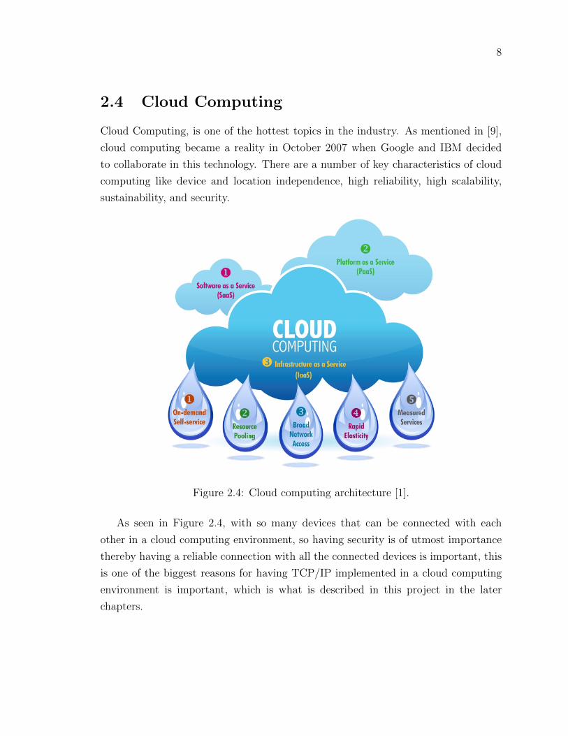
Cloud Computing, is one of the hottest topics in the industry. As mentioned in [9],
cloud computing became a reality in October 2007 when Google and IBM decided
to collaborate in this technology. There are a number of key characteristics of cloud
computing like device and location independence, high reliability, high scalability,
sustainability, and security.
Figure 2.4: Cloud computing architecture [1].
As seen in Figure 2.4, with so many devices that can be connected with each
other in a cloud computing environment, so having security is of utmost importance
thereby having a reliable connection with all the connected devices is important, this
is one of the biggest reasons for having TCP/IP implemented in a cloud computing
environment is important, which is what is described in this project in the later
chapters.

9
2.5 Summary
This chapter gave a brief description of the technologies used for this project along
with giving some advantages of using these technologies over others and provides
rationale as to why they were used. The next chapter will give a brief description of
all the components used in the simulations designed in this project.

10
Chapter 3
Simulation Components
This chapter describes all the components that were used in designing the simula-
tions in this project. This chapter is divided into three different sections. First, a
description of all the components in the main simulation using iCanCloud created
in the project is given. Then, a description of the components within a NodeVL is
given. Finally, the components within a router are described.
3.1 Components of the iCanCloud simulation
Figure 3.1: iCanCloud simulation.

11
Is used for communication within the network in iCanCloud. It
is different from the typical Standard host node used in the INeT framework, i.e. A
Standard Host has an architecture very similar to that of a router which is explained
in section 3.3, whereas in the NodeVL all the components like the Memory, Storage,
Operating System and the CPU are all embedded within the node itself. All these
components are linked to the hypervisor responsible for linking the four components
of the NodeVL with the network layer.
As described in [23] the Router used in the simulations is the
IPv4 router which supports wireless, Ethernet, PPP(Point-to-point Protocol) and
external interfaces. It can be connected to other nodes using the pppg or the eth gate.
For it to support a different routing protocol like OSPF(Open Shortest Path First
Protocol), RIP(Routing Information Protocol) or BGP(Border Gateway Protocol)
the hasOSPF/hasRIP/hasBGP parameters can be set to add any of these protocols
to the router.
By the name, it suggests that this node should be respon-
sible for generating users, in a way it does generate users but in a different way. It
defines a cell which consists of four groups which together constitute a single user,
i.e.
• Number of virtual machines that a user requires is given by the VmDefinition
parameter.
• Type of distribution that has to be defined by the user is given by the Distri-
butionDefinition parameter.
• Definition of the set of applications that a user will launch is given by the
AppDefinition parameter.
• Module interface used to create the users is given by the IUserGenarator pa-
rameter.
Responsible for managing the different jobs created to
be handled using the scheduling technique defined in the initialization file. By default,
there are three types of scheduling techniques defined in iCanCloud i.e.

12
• First-Come-First-Serve scheduling (FCFS).
• Priority scheduling.
• Round Robin scheduling.
For the simulation in Figure 3.1 the FCFS (First-Come-First-Serve) type of scheduling
was chosen to manage different jobs by the Job Manager.
As described in [23] the Network Manager is responsible
for managing the network as its name suggests. It manages all the Physical IPs
allocated to all the nodes in the network. It also assigns Virtual IPs to all the Virtual
Machines (VMs) assigned to each physical node in the given network.
Consists of two submodules, each containing one parameter,
• The first submodule consists the number of computing nodes in the network.
• The other submodule consists the number of storage nodes in the network.
Is a vector that points to the VmImage node in the simulation.
The Virtual Machine Image (VMImage) is defined in iCanCloud as a Virtual Machine
i.e. a machine without any physical resources. The physical resources for this machine
are managed by the hypervisor and the virtual machine is linked to the hypervisor
for performing tasking using the physical resources. There are four main parameters
that define a virtual machine in the simulation:
• Identification: Represents a string which gives each virtual machine a unique id
thereby giving a way to uniquely identify the virtual machine.
• NumCores: Defines the total number of cores that will be assigned to the specific
virtual machine.
• MemorySizeMB: Defines the memory size in Megabytes (MB) to a particular
virtual machine will be assigned.
• StorageSizeGB: Defines the total storage in Gigabytes (GB) to a particular
virtual machine will be assigned.

13
As described in [23] the Network Configurator is
responsible for assigning IP addresses and setting up a static routing type interface for
an IPv4 network. It assigns each interface in the network with a unique IP address,
but at the same time, it takes into account the subnet of each of the interfaces to
which an IP address is being assigned. The configurator also has the capacity to
optimize the routing tables generated for the network by merging specific routing
entries in the routing table. The Configurator is capable of assigning addresses in a
network both manually or automatically, i.e. The user can provide the address and
the netmask templates with some parts that are unspecified and the configurator will
automatically complete them by putting the nodes on the same LAN belonging to
the same subnet. Another feature of the configurator is that it supports both manual
and automatic routes for the nodes in a way that the assigned route will be designed
to follow the shortest path possible. For the configurator to recognize a network node
i.e. a host, bus, switch, router, etc., each of them needs to have the @node property
which allows the configurator to recognize the nodes in the network.

14
Figure 3.2: Data Rate Channel Architecture [23].
Data Rate Channel: A channel in iCanCloud is used to add certain metrics that
can be calculated and be recorded in the results section of the simulation. Like by
using the Data rate channel as given in [23] metrics like, throughput of the network,
utilization of the channel between the nodes, how busy each channel is when the
simulation is running, how many packets are discarded by the channel when the
simulation is running, the amount of memory in bytes of the packets that are being
forwarded through the channel and the total number of packets being transferred over
the channel in the entire simulation.

15
3.2 Components within a NodeVL
Figure 3.3: Design of the architecture inside a NodeVL.
Used as an interface to implement the TCP protocol. This is the central
node which is responsible for setting up the connections and linking the hypervisor,
the network layer, and the tcpApp.
Responsible for linking each virtual machine to an instance of
the physical resource like, CPU, Memory, Network, and Storage. All these resources
are linked to the hypervisor with the help of controllers for each resource. There are
a number of metrics that need to be specified in the hypervisor module:
• numStorageServers: Number of physical storage servers that will be needed by
the virtual machines based on their storage needs.

16
• numCPUs: Number of physical CPUs that will be needed by the virtual ma-
chines for their computing needs.
• memorySizeMB: Amount of physical memory needed in Megabytes (MB), which
will be based on the type of data or amount of data which will be processed by
the virtual machines.
• blockSizeKB: Size of the physical blocks in Kilobytes (KB) which denotes the
size of each block that will be processed by the virtual machine.
• storageSizeGB: Amount of physical storage space in Gigabytes (GB) that the
virtual machines need for storing any kind of data.
• numNetworkInterfaces: Number of physical network interfaces that the hyper-
visor might be linked to based on the needs of the virtual machine.
• IP: Defines the IP address of the physical node.
• storageAppModuleIndex: Index of the storage module that is linked to the
hypervisor.
• connectionTimeOut: Time limit from when a message has been sent by the
hypervisor until the time when the hypervisor gets back the response.
• networkServiceType: Type of network service that is being used by the hyper-
visor. In our case the network service being used is TCP.
Acts as a template for the TCP application that will be used by
the network. It displays the type of gates that will be needed by the TCP application
so that TCP can be used in the network for communication between the various
nodes. In our case, the type of applications used is the TCPSessionApp and the
TCPEchoApp, for which only the tcpIn and the tcpOut gates are needed by the
application. The SessionApp is used for creating a connection(session) between the
nodes, where after the connection is open the application sends the given number
of bytes and then closes the connection. The EchoApp is used to receive the data
packets that arrive through a TCP connection. Other applications available are the
TCPGenericsSrvApp and the TCPBasicClientApp.

17
Links different interfaces based on the link layer that can be
utilized by the node in the simulation. There are four different interfaces that can be
applied in our simulation, i.e.:
• lo0 (Loopback Interface) [3]: Can be utilized to identify the device in the net-
work, i.e. the loopback address can be used to check whether a particular device
is online on the network as the loopback address remains constant and does not
change.
• ext (External Interface) [13]: Relates to a real interface on the host node that
is running the simulation. This type of interface is very useful for hardware-
in-the-loop simulations. Hardware-in-the-loop simulations is a technique that
is used in the development and in the testing purpose for real-time embedded
systems.
• eth (Ethernet Interface) [4]: Node that acts as a prototype for the link layer
protocol dealing with the ethernet interface. This is the type of interface that
allows a physical device like a computer or a mobile device or in our case a
node in the simulation with the other nodes in the network using ethernet as
the transmission medium. In iCanCloud an ethernet interface is used with the
notation(ethg) and is used to connect different nodes with each other through
a channel.
• ppp (Point-to-point Interface) [20]: Implements the point-to-point protocol in
the network. PPP is the type of protocol that gives strong emphasis on the
configuration of the links in the network and their maintenance. In the routers,
this model relies on the queue model to request for packets from the queue
and forward them one-by-one. Similarly, in the nodes, there is no such queue
present so the ppp model creates its own queue(txQueue) and aligns the packets
in this queue where the packets will be waiting for transmission. In iCanCloud a
point-to-point interface is used with the notation(pppg) and is used to connect
different nodes with each other through a channel.
In the simulation, either the ethg(Ethernet Interface) or the pppg(point-to-point In-
terface) can be used to connect different nodes with each other.

18
Stores the routing table of the network. The routing table
basically consists information regarding the routes to specific network destinations.
The routing table also consists information regarding the topology of the network
present around it, like in the given simulation the routing table consists information
like,
• routerID: Is left empty if the node is a computing or a storage node. If the node
is a router then the router ID will already be set.
• IPForward: Is used to set IPforwarding feature for a node which determines the
route that will be taken to send a packet to another node in the network. By
default, this parameter is set to true.
• forwardMulticast: Is used to set multicast forwarding feature for a node which
determines whether a packet will be sent to multiple destinations in a single
transaction. By default, this parameter is set to false.
• routingFile: Consists the name of the file that contains the routing table for a
particular node. By default this parameter is empty.
Is responsible for containing information regarding the net-
work interfaces that have been registered for a particular node in the network. This
table only contains protocol-independent properties of interfaces, i.e. routing capa-
bilities and features that are not specific to a particular routing protocol, like a static
route can be defined using a protocol-independent property and then this static route
can be redistributed in the network using a routing protocol. This node has only one
parameter used in the simulation i.e.:
• displayAddress: This parameter is used to ask the user whether the IP addresses
should be displayed on the links in the network. By default, this parameter is
set to true.
Notifies all the other nodes in the network regarding any
changes like,

19
• Changes or updates made in the routing table of one node.
• Interface status changes in the interface table.
• Changes made in the state of the wireless channel.
• Wireless handovers being made in the network.
• The position change of a mobile node.
These are the changes that can take place in a network over time, and so to keep track
of all these changes and notifying other nodes of these changes the notificationBoard
is used in all the computing or the storage nodes present in the network.
Consists of parameters for all the controllers that are linked
to the hypervisor for measuring the energy being utilized by each of those controllers
in the simulation. The parameters defined in the node are:
• cpuMeterType: Representing the cpuModule controller.
• memoryMeterType: Representing the memory controller.
• storageMeterType: Representing the storageSystem controller.
• networkMeterType: Representing the osModule controller.
Is the power supply unit used by a specific node while running in the
simulation. It has two parameters,
• Wattage: This is the power output in watts for the node.
• Scale: This is the time it takes to recalculate the energy lost by the power
supply unit (psu) after the simulation is complete.

20
3.3 Components within a router
Figure 3.4: Internal Architecture within a router.
There are a number of important components present in the router which are
similar to the components present within a NodeVL, like:
• A router has a routing table, interface table, and a notification board node. All
these nodes perform the same functions inside a router as they do for a NodeVL.
• There is also a network layer present in the router which performs all the func-
tions similar to the network layer present in the NodeVL, but along with those
features the network layer has some additional features that it performs only in
the router and not in the NodeVL, i.e.:
– Along with the four interfaces present in the network layer of the NodeVL
i.e., lo0 (loopback Interface), ext (external Interface), eth (ethernet Inter-
face) and the ppp (point-to-point Interface), there is a fifth interface that
can be used by the router which is the WLAN ( wireless Interface) which
can be used for using the router to connect to different devices in a wireless
computer network rather than a wired network.
– The network layer in the router also has an option to implement different
protocols in the simulation, like:

21
∗ TCP (Transmission Control Protocol) [18]: Is the most popular proto-
col among the internet protocol suite. TCP is responsible for providing
a reliable, ordered and an error-checked system for delivering packets
among nodes communicating with each other over an IP network.
∗ UDP (User Datagram Protocol) [17]: Is one of the core members of
the internet protocol suite. In this protocol communication between
nodes over a network takes place in a way similar to the TCP protocol,
but the only difference in UDP is that there needs to be no prior com-
munication between the nodes before packets are sent between them
which is why UDP is not considered a secure means to communicate
over a network as compared to TCP.
∗ BGP (Border Gateway Protocol) [19]: Is used to make routing de-
cisions based on the paths and the network policies that have been
configured by the network administrator. As a result of the functions
that this protocol is responsible for it is sometimes called as the path
vector protocol and sometimes it is called as a distance-vector routing
protocol.
∗ RIP (Routing Information Protocol) [7]: Is one of the oldest distance-
vector routing protocols making use of the hop count strategy for
applying any kind of routing in the network. The maximum allowed
hop counts in this protocol are 15 which is one of the reasons why this
protocol is not very popular now as it limits the size of a network that
the protocol can support.
∗ OSPF (Open Shortest Path First) [14]: Is an interior gateway protocol
responsible for transmitting packets within a single routing domain.
It detects changes in the topology, links failures and constructs a new
routing structure within seconds. This protocol does not use TCP
or UDP for transmitting packets, so it is not a very secure means of
communication in a network.
Based on the requirement of the simulation any of these five protocols can be used
and implemented. In our case TCP protocol has been implemented in the simulation.
As mentioned in [11] the Pcap recorder is responsible for

22
capturing the pcap (packet capturing) traces for the frames of packets that have
been sent or received by the other modules or components present in the same node,
i.e. a NodeVL or a Router. This node also has the capability to print a tcpdump
like information in the form of a log file. Tcpdump is basically a file containing the
TCP/IP information regarding the packets being sent or received within the network.
Is used for as the name suggests mobility model as explained in [21],
i.e. models that represent the movement of mobile users and their location, velocity
or acceleration can change over a certain time frame. This node consists of a single
parameter:
• mobilityStateChanged: This is a signal that will indicate to the router whether
the state of a node or any other component in the network has changed from
its previous position.
Is for the usage of battery models, i.e. in simulations where the
main aim of the simulation is to conserve energy or to conserve less battery life that is
where the battery models come in the picture. This node has no parameter it is just
used as an interface to link the battery module interface in the inet.battery package
that is provided in the OMNeT++ framework.
Is responsible for keeping track of the status of a node in a particular
network i.e. whether the node is up, down, idle, not connected or any other status
that a node can have depended on the type of node in the network. This node consists
of two parameters, i.e.:
• initialStatus: Gives the initial status of a node in the network which in our case
if the node is a router then the default status is up.
• nodeStatusChanged: Is a signal that indicates to the other nodes in the network
whether the status of a node has changed from its previous state.

23
3.4 Summary
Important Components DescriptionNodeVL Used as the main node in the simulation.Router Used to transfer information.
Data Rate Channel Used to connect all the nodes with the routers.Configurator Used to assign IP address.
userGenerator Used to generate users.manager Used to manage jobs.
networkManager Used to manage the network.vmSet Vector pointing to the vitual machine.
topology Defines the computing and storage node quantities.
Table 3.1: Important components used in the iCanCloud simulation.
This chapter gave a brief overview of all the components used in the simulations
created. The next chapter will describe the process of designing those simulations.

24
Chapter 4
Simulation Designs
This chapter begins with explaining how TCP/IP is implemented in OMNeT++
and based on that two simulations were designed to explain the working of TCP/IP.
Finally, the process of designing the simulation using iCanCloud is explained.
4.1 Understanding TCP/IP in OMNeT++
In order to understand and implement a working simulation with a working model of
TCP/IP implemented successfully in OMNeT++ using iCanCloud, it is important
to understand which package is used in OMNeT++ for implementing TCP/IP. This
was the first task in the design process of the simulations used in the project, and
the answer to this question was INET which is another package included along with
OMNeT++ which is responsible for implementing TCP/IP in OMNeT++. A detailed
explanation along with the working of various components in the INET framework
are explained in [23]. There are multiple types of TCP applications provided in the
INET framework like,
• TCPSessionApp
• TCPEchoApp
• TCPBasicClientApp
• TCPGenericsSrvApp
For designing a simulation in OMNeT++, there are two basic components that
are important and that have to be present in each and every simulation i.e. the ini file

25
that is used to initialize all the parameters that will be required to run the simulation
and the NED file in which all the components that will be used in the simulation
will be setup and connected in the design view in the OMNeT++ editor.
4.2 Simulation design for one client and server us-
ing TCP/IP
Figure 4.1: Simulation between a single client and server.
Figure 4.1 shows the design view of the NED file. In this view, all the components
that will be used to carry out the client-server simulation can be visualized. There is
another view for the NED file which is the source view which shows all the components
that were added in the design view along with their exact position in the design
view. Also, the source view shows the number and type of channels that were used
in the simulation and which components were connected using the channels in the
simulation.

26
Figure 4.2: NED File source view for the client-server simulation.
Figure 4.2 shows the source view of the NED file for the client-server simulation
shown in Figure 4.1. Figure 4.2 shows, that there is one channel used in the simu-
lation. The submodules are basically all the components that have been used in the
simulation and the connections section shows the components that are connected to
each other which in this case is the client and server.
Now after the NED file comes the ini file that is used to initialize all the parameters
that are required to run the simulation.

27
Figure 4.3: TCPSessionApp configuration for client-server simulation.
Figure 4.3 shows the ini file for the TCPSessionApp used for the client-server sim-
ulation described in this section. The TCPSessionApp simply is a single connection
application, which means it opens a connection, then sends the total number of bytes
through that connection and then closes the connection. A more detailed explanation
of the TCPSessionApp and each of the parameters initialized in the ini file is given
in [23].
Figure 4.4: TCPEchoApp configuration for client-server simulation.
Figure 4.4 shows the ini file for the TCPEchoApp, the other TCP application used
for the client-server simulation along with the TCPSessionApp. The TCPEchoApp
has a functionality of receiving data packets that are being sent by one node(in this
case client) to the other node(in this case server) through TCP. A further explanation
of the TCPEchoApp is given in [23].

28
4.3 Simulation design for multiple clients and servers
using TCP/IP
Figure 4.5: Simulation between multiple clients and servers.
Figure 4.5 shows the design view of the NED file of the simulation between multiple
clients and servers. This simulation is a little different from the one described in
section 4.2 where there only a single server and client that were directly connected
with each other without having any routers in between them, whereas in this section
the simulation has four clients and two servers that connected with each other through
routers. Also in this simulation, there are three channels defined to connect the nodes
with each other.
Figure 4.6: NED file showing the connections between multiple clients and servers.
Figure 4.6 shows all the connections that have been made in this simulation, like
• C1 is the channel used to connect all the client nodes to the first router namely
router1.

29
• C2 is the channel used to connect the different routers with each other.
• C3 is the channel used to connect both the servers with second router namely
router2.
Figure 4.7: TCPBasicClientApp configuration for multiple clients-servers simulation.
Next, comes the ini files used in this simulation. Similar to the simulation de-
scribed in the previous section, this simulation also uses two different TCP Appli-
cations i.e, the TCPBasicClientApp and the TCPGenericsSrvApp. Figure 4.7 shows
the code snippet used to initialize the TCPBasicClientApp in this simulation. The
TCPBasicClientApp has a functionality fairly similar to the TCPSessionApp where a
single TCP connection is opened by the client, then it sends through the connection
and then closes the connection. There is some other functionality and features related
to the TCPBasicClientApp which can be found in [23].
Figure 4.8: TCPGenericSrvApp configuration for multiple clients-servers simulation.
Figure 4.8 shows the code snippet of the TCPGenericSrvApp used in this simula-
tion. Similar to the TCPEchoApp described in section 4.2, the TCPGenericSrvApp
has a functionality of receiving any number of TCP packets. The only difference in
the TCPGenericSrvApp is that it can only receive packets with GenericAppMsg class
on them which is the reason for pairing the TCPGenericSrvApp with the TCPBa-
sicClientApp because this app sends packets, but with the GenericSrvApp class on
them. All the other parameters that can be initialized along with TCPGenericSrvApp
are explained in [23].

30
4.4 Design of iCanCloud simulation using TCP/IP
Figure 4.9: iCanCloud simulation.
Figure 4.9, shows the design view of the NED file for the iCanCloud simulation
created in this project. On comparing the two simulations described in section 4.2 and
4.3, this simulation has some similar components. But there are some important com-
ponents used in this simulation which is different from the previous two simulations,
instead of a client and a server, in iCanCloud a nodeVL is used. Other dissimilarities
include the vmSet, topology, networkManager, JobSceduler and userGenerator. All
these components have been described in section 3.1 of the previous chapter.
Figure 4.10: Bandwidth of the channels used in iCanCloud simulation.

31
Figure 4.10 shows the bandwidth of all the channels that been used to in the
connections made in the iCanCloud simulation.
Figure 4.11: Connections made in the iCanCloud simulation.
Figure 4.11 shows the connections that have been made in the iCanCloud sim-
ulation. Similar to the simulation with multiple clients and servers in the previous
section, there are three channels in this simulation also but the way these connections
are made is different.
• The first channel(RackChannel_0_TCP_NodeVL) is used to connect the first node
(rc_0_Rack_A_16[0]) to the first router(router0) and the same channel is also
used to connect the second node(rc_0_Rack_B_16[0]) to the second
router(router1).
• The second channel(Channel_0_TCP_NodeVL) is used to connect the first
router(router0) to the third router(router2) and the same channel is also used
to connect the third router(router2) to the last node(ns_0_NodeStorage_C).
• The third channel(Channel_1_TCP_NodelVL) is used to connect the second
router(router1) to the third router(router2) and the same channel is also used
to connect the third router(router2) to the last node(ns_0_NodeStorage_C).
Similar, to the previous two simulations two TCP applications are used to set up
the TCP connections between two nodes in this simulation. The only question is that
which two TCP applications have been used and what was the reason for choosing
these applications?
• Firstly, as seen from the previous two simulations the TCPBasicClientApp is
more useful when used in the case of multiple clients and multiple servers, which
is the case for the simulation in section 4.3, while in the case of a single client
and a server the TCPSessionApp is better.

32
• Another reason is that along with the TCPBasicClientApp there is another con-
dition, i.e. it needs to be paired with the TCPGenericSrvApp as the messages
that are sent from this application have the GenericSrvApp class on them which
cannot be read by the TCPEchoApp.
Figure 4.12: TCPSessionApp configuration used in iCanCloud simulation.
Figure 4.12 shows the TCPSessionApp configurations that have been used in the
iCanCloud simulation.
Figure 4.13: TCPEchoApp configuration used in iCanCloud simulation.
Figure 4.13 shows the TCPEchoApp configurations that have been used in the
iCanCloud simulation.
Along with the TCP applications, there are other parameters that have been
initialized in this simulation. Figure 4.14 shows the snippet of the ini file where the
main parameters that have been used in the iCanCloud simulation are initialized.
Some of the terminology used to define the parameters in this section is different
from the previous two simulations, like
• The client and server node are called as the compute nodes in iCanCloud.
In the given simulation there are two compute nodes, i.e. computeNode0
(rc_0_Rack_A_16) and computeNode1 (rc_0_Rack_B_16).

33
Figure 4.14: Main parameters in the iCanCloud simulation.
• There is a third node in the iCanCloud simulation called as the storage node
whose structure is similar to the compute nodes and is also defined as a TCPE-
choApp which is the second server in the simulation. In the given simulation
this node is named as(ns_0_NodeStorage_C). The main purpose of using this
node is that, in case there is any failure in the first server or the link between
the router and the first server fails this node can act as the server node in the
iCanCloud simulation.
After all, the main parameters are initialized then each component inside a NodeVL
needs to be initialized. There are four main components inside each NodeVL i.e.,
cpuModule, storageSystem, memory and the osModule. Apart from these four, there
are two other things that are part of the operating system module of a NodeVL
that are also initialized is the vmModule(initializing the Volume Manager) and the
fsModule(initializing the File System).
Figure 4.15 shows the snippet of the ini file for the
node storage (ns_0_NodeStorage_C), where all the above mentioned six components
have been initialized for the iCanCloud simulation.
• The first set of parameters to be initialized belong to the CPU System like cpu
core type, speed of the core and the ticks per second of the core while it is
running.

34
Figure 4.15: Components inside a NodeVL in iCanCloud.
• The second set of parameters represent the Storage System like device type,
type of the cache, read and write bandwidth of the device.
• Next, comes the Memory system parameters like the latency time (for reading,
writing and searching in seconds), number of RAM chips and number of modules
in the system.
• Next are the Operating system and the type of scheduler that has been used in
the system.
• Next is the Volume manager parameters like storage manager type, schedule
type and the cache type used in the operating system module.
• Finally, there is the File system and the file system type that is used by the
operating system module.

35
4.5 Summary
This chapter gave an overview of how TCP/IP is implemented in OMNeT++ and
what kind of applications can be used to implement TCP/IP. Based on these ap-
plications three simulations were designed to show how TCP/IP can be used in
OMNeT++. The next chapter will describe the working of the three simulations
described in this chapter, along with an evaluation of the simulations and an analysis
of the proposed environment, with some limitations of this project and ends with
some sample assignments.

36
Chapter 5
Working, Evaluation, Analysis of
Simulations, Challenges and
Sample Assignments
This chapter begins with an explanation of how to run and then start a simulation
in OMNeT++. Then the three simulations described in the previous chapter, are
explained. Then an evaluation of all the simulations in this project is given. Then an
analysis of the proposed simulation environment is done along with some strengths
and weaknesses of the proposed environment. Then some limitations of this project
are given. Finally some sample assignments are given, that show how the project can
be used to create different types of simulations by someone unfamiliar with the tool.
5.1 Running and starting a simulation in OMNeT++
Now, before running a simulation in OMNeT++ the NED file and ini file, which
define and initialize all the components needed to run the simulation are required.
From the previous chapter, both these files have been included for all the simulations
designed.
Next step is running the simulation. For this purpose, there are two ways of doing
this,
• The first way is to right-click on the ini file in the project explorer in OMNeT++,
which will give an option to run the simulation as an OMNeT++ simulation.

37
• The other way is to click on the play button marked with the circle in the Figure
5.1 to run the simulation.
Figure 5.1: Play button to run the simulation.
After running a simulation using any of the above mentioned two steps another
window comes up, where the actual simulation environment the way it was designed
in the NED file can be seen. In this window, there is a run button marked with the
black circle in Figure 5.2.
Figure 5.2: Run button to start the simulation.
On clicking the run button in the Figure 5.2 the simulation starts by first initial-
izing all the components of the simulation as mentioned in the ini file and then the
actual packet transfer can be seen between the nodes defined in the simulation.
5.2 Working of simulation with one client and server
using TCP/IP
Figure 5.3: Initializing components of the simulation network.

38
Figure 5.4: Run window for simulation with one client and server.
For the simulation with one client and server, on clicking the play button in Figure
5.1 the run window Figure 5.4 comes up. In this window, after each of the components
in the ini file are initialized properly in Figure 5.3 each node that is connected through
a channel is assigned an IP address as seen in Figure 5.4.
After the run window comes up in Figure 5.4, the next step is to run the simulation
by clicking the run button in Figure 5.2. Before the packet transfer can take place
using TCP, first a reliable connection needs to be established between the two nodes
which in this case are the client and the server nodes. The process of establishing
this connection is called as three-way handshaking, in which
• First, a SYN(Synchronize) packet is sent from the client to the server in Figure
5.5.
• Next, the server sends a SYN+ACK(Synchronize and Acknowledgement) packet
to the client thereby acknowledging that the server has received the SYN packet
from the client.
• Then finally the client sends an ACK packet to the server acknowledging that
the client has received the SYN packet from the server.
• Once this three-step procedure is completed successfully, a reliable connection
between the client and the server is established.
After the three-way handshaking between the client and the server is complete
the packet transfer between the client and the server begins.

39
Figure 5.5: SYN packet being sent to the server.
In Figure 5.5, a SYN packet is being sent from the client to the server. In the
same way all the other packets for the three-way handshaking are sent.
Figure 5.6: TCP packet transfer.
Figure 5.6 shows the TCP packet begin sent from client to server. Once this
packet transfer begins, on each step i.e., if the client is sending something to the
server or if the client is receiving something from the server at every step an additional
ACK(acknowledgment) packet is also sent to the sender of the packet acknowledging
that they have received the packet. This way once both the client and server has sent
the packets the TCP connection established between the nodes is closed.

40
5.3 Working of the simulation with Multiple clients
and servers using TCP/IP
Figure 5.7: Initializing components for multiple clients and servers simulation.
In Figure 5.7, similar to the simulation in the previous section on clicking the play
button as in Figure 5.1 the components of the simulation with multiple clients and
servers are initialized if both the ini and NED files are included and defined properly
for the components included in the simulation.

41
Figure 5.8: Run Window for simulation with multiple clients and servers.
Also on clicking the play button another part that comes up is the run window
in Figure 5.8. The way each node is assigned an IP address in the run window in
Figure 5.4, the same way each node in the run window in Figure 5.8 is also assigned
an IP address. But, in this simulation along with multiple clients and servers there
are routers as well and in a router with every link that is coming in the router is
assigned an IP address. Every link going out from the router will also have an IP
address assigned to it, which in this case is,
• For the first router(router1), it has four links coming in from each of the
four client nodes and the link going out of the router1 connects to the other
router(router2). So in total, the first router has 5 IP addresses assigned to it.
• For the second router(router2), it has one link coming in from the first router
and two links that are going out to the two server nodes. So in total, the second
router has 3 IP addresses assigned to it.
After all the components are initialized properly, the simulation can be started
by clicking the run button in Figure 5.2. On clicking this button first the three-way
handshaking will take place between the client and the server nodes the same way it
was done in the previous simulation between one client and server.

42
Figure 5.9: SYN Packet being sent from client1 to the server1.
In Figure 5.9, a SYN packet is being sent from client1 to router1. The router1
will then send the SYN packet to the router2 and finally, router2 will send it to the
destination node for the packet i.e. server1. The same process will be repeated by
client 2 which will send a SYN packet to be received by server2. This completes the
first step of three-way handshaking.
Figure 5.10: SYN+ACK packet sent from server1 to client1.
After both the servers have received the SYN packet from the clients, then the
server will send the SYN+ACK packet to the client acknowledging that they have
received the earlier sent SYN packet from the client. Figure 5.10 shows the server1

43
sending the SYN+ACK packet to the router2. Then router2 sends this packet to
router1, which is finally received by client1. The same process is done by server2,
which sends the SYN+ACK packet to client2. This completes the second step of
three-way handshaking.
For the final step, both the client nodes send an ACK packet to the server nodes
acknowledging that they received the SYN+ACK packet sent from the server and are
ready to establish a TCP connection. After both the servers receive the respective
ACK packets sent from the clients the connection is established. Now the data transfer
begins.
Figure 5.11: TCP packet transfer.
Figure 5.11 shows data being transferred from client2 to router1, which will be
finally received by server2 via router2. The steps are as follows:
• After the server receives the TCP packet it sends an ACK packet to the client
acknowledging that it has received the TCP packet.
• Then the server sends a TCP packet to the client.
• Now the client will send an ACK packet to server acknowledging that it has
received the packet from the server.
• Along with the ACK packet, the client also sends the FIN packet to the server,
indicating that the packet transfer between the client and the server has com-
pleted.

44
• On receiving this FIN packet, the server then sends an ACK packet to the client
acknowledging that it has received the FIN packet from the client.
• Finally, the server sends a FIN packet to the client indicating that it has finished
the packet transfer as well.
• On receiving this FIN packet the client, sends a final ACK packet to the server
and then the connection is closed.
• Now, after the connection is closed to send further packets the entire process
explained in this section about three-way handshaking for TCP takes place
again and then the packet transfer begins again.
5.4 Working of iCanCloud simulation using TCP/IP
Figure 5.12: Initializing network for iCanCloud simulation.
Figure 5.12, shows the network initialization that takes place similar to the simu-
lations in the previous two sections. This initialization for the iCanCloud simulation
begins on clicking the play button in Figure 5.1. The initialization completes properly
only if all the parameters of simulation components are initialized in the ini file and
configured in the NED file.

45
Figure 5.13: Run Window for iCanCloud simulation.
Figure 5.13 shows the run window which also comes up along with the initialize
window in Figure 5.12 on clicking the play button. The way IP addresses are assigned
to the nodes for the simulations in the previous two sections, the same way in this
simulation also each node connected with a channel is assigned an IP address. As
in this simulation, there are routers as well, so each router will be assigned two IP
addresses the same way it was done for the simulation with the multiple clients and
servers.
Figure 5.14: SYN packet being sent from rc_0_Rack_A_16[0] to router1.
On clicking the run button in Figure 5.2, the three-way handshaking process begins
where, in the first step the SYN packet is sent from the rc_0_Rack_A_16[0] node to

46
the first router(named router0) shown in Figure 5.14. Then from router0, this SYN
packet travels via router2 to get to router1 and finally to arrive at the destination
node i.e. rc_1_Rack_B_16[0].
Figure 5.15: SYN+ACK packet sent from rc_1_Rack_B_16[0] to router1.
After the first step for the three-way handshaking is complete, then in the next
step, the rc_1_Rack_B_16[0] node sends the SYN+ACK packet to the router1,
which will finally reach its destination which is rc_0_Rack_A_16[0] node traveling
via router2 and router0.
For the final step, the rc_0_Rack_A_16[0] node will send an ACK packet to
the rc_1_Rack_B_16[0] node, there by finishing the three-way handshaking and
successfully establishing a reliable TCP connection between the two nodes.
After the three-way handshaking process is complete, the TCP packet transfer
process begins.
• Figure 5.16 shows the TCP packet being sent from rc_0_Rack_A_16[0]
node to the router0. This packet is finally received by the destination node
rc_1_Rack_B_16[0], traveling via the router2 to router1.
• On receiving the packet the rc_1_Rack_B_16[0] node sends the ACK packet
to the rc_0_Rack_A_16[0] node acknowledging the earlier packet sent was re-
ceived.
• Then the rc_1_Rack_B_16[0] sends a TCP packet to the rc_0_Rack_A_16[0]
node.

47
• On receiving this packet the rc_0_Rack_A_16[0] node sends an ACK packet to
the rc_1_Rack_B_16[0] node thereby completing the packet transfer process
between the two nodes.
Finally, the TCP connection established between the two nodes is closed after
the packet transfer process is completed.
Figure 5.16: TCP packet transfer in iCanCloud simulation.
5.5 Evaluation
The simulation with TCP/IP implemented in iCanCloud shown in Figure 5.13 is the
main simulation created to achieve the goal of this project. Evaluating this simulation
depends on,
• Evaluating the design and working of the first two simulations created for this
project.
• Comparing all the components used for all the three simulations.
• The TCP applications used in all the simulations.
• The type TCP support available for all the three simulations.
So just for the purpose of evaluation of all the three simulations, let’s call,

48
• The first simulation with one client and server as Simulation 1.
• The second simulation with multiple clients and servers as Simulation 2.
• The last simulation using iCanCloud as Simulation 3.
Parameter Simulation 1 Simulation 2 Simulation 3
Used
One Client, Four Clients, One Client, Two ServerComponents One Server, Two servers, Three routers, configurator
configurator, Two routers, networkManagerand netAnimTrace configurator jobManager, userGenerator
and controller vmSet and topology.
TCP Application TCP Session App TCPBasicClientApp TCP Session AppUsed TCP Echo App TCPGenericsSrvApp TCP Echo App
TCP Support Full Support Full Support No Support
Table 5.1: Comparing the three simulations.
From the Table 5.1, there are some similarities and some differences present in
Simulation 1, Simulation 2 and Simulation 3 which can also be seen in Figure 5.4
for Simulation 1, Figure 5.8 for Simulation 2 and Figure 5.13 for Simulation 3. The
reason for that is,
• First, the Simulation 1 and 2 are based on the INET framework present in OM-
NeT++ and Simulation 3 is based on the iCanCloud Framework for OMNeT++
in which INET framework is used for implementing TCP.
• Second, Simulation 1 and 2 were designed for the purpose of understanding how
TCP is implemented in OMNeT++ using INET, but Simulation 3 was designed
to see how using iCanCloud in OMNeT++ TCP can be implemented or not.
• Third, in case of the TCP support section as mentioned in Table 6.1 Simulation
1 and 2 are based on INET, which means that as mentioned in [23] there are
a bunch of predefined packages implemented in INET for implementing TCP.
But in iCanCloud used for Simulation 3, there is no TCP support so TCP ap-
plications from INET had to be used along with using iCanCloud to implement
TCP for Simulation 3.

49
• Fourth, for the type of TCP Applications that were used for all the three simu-
lations are used in pair’s, because the design of TCP in INET is such that there
is one application that is used for the client-side implementation of TCP and
the other application is used for the server-side implementation of TCP.
• Finally, in the case, where there is one client and one or multiple servers then
the client-side application is always the TCPSessionApp and the server-side
application is always TCPEchoApp , and when there are multiple clients and
multiple servers involved in the simulation then the client-side application is
TCPBasicClientApp and the server side application is TCPGenericsSrvApp,
the reasons for this are:
– With TCPSessionApp the packet sent does not have the GenericsSrvApp
class set which is required by the TCPGenericsSrvApp to receive the packet
sent. So the TCPSessionApp is paired with the TCPEchoApp.
– The packet sent using the TCPBasicClientApp has the GenericsSrvApp
class set which can be received by the TCPGenericsSrvApp, so the TCP-
BasicClientApp is paired with the TCPGenericsSrvApp.
For all the components compared in Table 5.1, a detailed explanation of each of
these components is given in chapter 3.
Apart, from the comparisons in Table 5.1 there are also some differences in the
design of all the simulations seen in the various Figures shown in chapter 4, i.e.
File Type Simulation 1 Simulation 2 Simulation 3NED File Figure 4.2 Figure 4.6 Figure 4.10
ini FileFigure 4.3 Figure 4.7 Figure 4.11Figure 4.4 Figure 4.8 Figure 4.12
Table 5.2: NED Files and ini files used for the three simulations.
From Table 5.2, all the Figures for the NED files and the ini files for all the three
simulations are mentioned.
• For the NED files, all the three are similar the only difference will be that as
the number of components in the simulations increase
– The types section of the NED file where the channels connecting the nodes
are defined will have more definitions for multiple channels.

50
– The submodules sections where what component included in the simulation
is defined will also increase.
– The connections sections where all the connections made in the simulation
is defined will also increase.
– A sample of the NED file can be seen in Figure 4.2.
• For the ini Files, Simulation 1 and 2 are similar but Simulation 3 has many
differences from the previous two simulations.
– As seen in the Figures for the ini files, in Simulation 1 and 2 basically all
the parameters that need to be initialized for the TCP application being
used for that simulation is given in the file.
– In Simulation 3 along with the TCP applications all the other components
within a client NodeVL (rc_0_Rack_A_16[0]) given in Figure 3.3 also
need to be initialized.
– Same components will be initialized for the first server NodeVL
(rc_1_Rack_B_16[1]) and the second server NodeVL
(ns_0_NodeStorage_C).
– A small sample of the ini file for Simulation 3 is Figure 4.12 defining
components within the ns_0_NodeStorage_C NodeVL.
5.6 Analysis
Based on the network traffic analysis and the performance analysis, the strengths and
weakness of the proposed simulation environment are described in this section.
5.6.1 Network traffic analysis
• From the table 5.3, at every stage before a packet transfer can begin between
the nodes in the network the first three packets need to be sent between the
client and server nodes, in the order they have been given in the table.
• After the first three packets have been sent and a connection is established then
the packet transfer process begins.

51
Type of Packet Sequence number for sending the packetSYN 1
SYN+ACK 2ACK 3
Packet 4FIN 5
Table 5.3: Types of packets sent in all the simulations.
• The total number of bytes of the information that is being transferred is set in
the ini file.
• Maximum size of each packet sent for transferring that information can be any
number of bytes that can be set in the ini file.
• So based on the total number of bytes set to be transferred, the number of
packets needed to transfer can vary.
• Finally after all the packets have been transferred then the last packet in table
5.3, FIN is sent indicating that the TCP connection between the nodes can be
closed.
So, this was just a basic theoretical analysis of the simulation environment. On
running the simulation, real simulated data is generated and can be analyzed using
Wireshark [5] a packet capturing tool.
Figure 5.17: Basic Layout of a wireshark packet capture.
Figure 5.17 gives an overview of the layout of how a packet capture window looks
like in wireshark. Each line in the figure is a frame giving information of what was
captured in the entire packet transfer process.

52
For the proposed environment the data is captured by running the simulation with
different number of bytes being sent in the network.
Figure 5.18: Different Frames captured using wireshark.
Figure 5.18 gives an analysis after running the proposed environment with seven
different configurations. As shown in the figure there are two kind of frames captured
i.e., the total number of frames shown with the blue circles and the number of dropped
frames shown with the red circles. The dropped frames are basically those frames that
were sent but for some reason were re-transmitted. The reason for this re-transmission
can be:
• The previous packet sent was not processed by the destination node, and before
that the new packet was sent, OR
• The destination queue queue might be full, and could not receive the new packet
right away.
This re-transmission of the packet is one advantage of using TCP in the network
as it does not discard that packet. Also from the figure it can be seen that the packet
re-transmission takes place only when the bytes being sent are 7000 or more.

53
Figure 5.19: ACK and Data Frames captured using wireshark.
Figure 5.19 gives an analysis of the number of ACK frames shown with the red
circles and the frames consisting of actual data shown with the green circles. Analyz-
ing this data shows that with using TCP, the amount ACK packets and the packets
containing data in them is almost the same, which means every ACK packet sent:
• Will be for acknowledging that the previous packet sent by the other node has
been received by the current node successfully, OR
• The current node has processed the previous sent packet and is ready receive
more data.
Figure 5.20: Different re-transmission frames captured in wireshark.

54
Figure 5.20 shows all the different re-transmission frames captured using wire-
shark. These frames are:
• Previous segment not captured.
• Duplicate acknowledgement.
• Fast re-transmission.
• Window Full.
• Re-transmission.
• Spurious re-transmission.
All of these frames are ultimately re-transmitted back in the network thereby restoring
the normal functioning of the network.
5.6.2 Performance Analysis
This section will give some performance analysis based on the throughput and uti-
lization of the simulation in Figure 5.13, simulation in Figure 5.23 with a bottleneck
link, simulation for assignment 1 and a simulation for assignment 1 with a bottleneck
link. Then there is a comparison between DropTailQueue and RED and finally an
analysis of the simulation in Figure 5.13 is done, using some bad configurations.

55
5.6.2.1 Simple iCanCloud simulation
This section shows the throughput and utilization of the simulation created in Figure
5.13.
Figure 5.21: Throughput of rackA and rackB in the iCanCloud simulation.
Figure 5.21 shows the throughput for both the rackA(rc_0_Rack_A_16[0]) and
rackB(rc_1_Rack_B_16[1]) in the iCanCloud simulation shown in Figure 5.13.
Figure 5.22: Utilization of rackA and rackB in the iCanCloud simulation.
Figure 5.22 shows the utilization for both the rackA(rc_0_Rack_A_16[0]) and
rackB(rc_1_Rack_B_16[1]) in the iCanCloud simulation shown in Figure 5.13.
The bandwidth used for all the channels in this simulation is 10Mbps.

56
5.6.2.2 Simple iCanCloud simulation with bottleneck link
This section shows the throughput and utilization of the simulation created in Figure
5.23.
Figure 5.23: iCanCloud simulation with bottleneck link.
Figure 5.23 shows the iCanCloud simulation with multiple clients connected to
the router0 and multiple servers connected to router1. This will create a bottleneck
link between the routers doing the packet transfer between the clients and servers,
i.e. the link between router0 and router2, and the link between router2 and router1.
Figure 5.24: Throughput of each node in the iCanCloud simulation with bottlenecklink.
Figure 5.24 shows the throughput for all the nodes in the iCanCloud simulation
with the bottleneck link in Figure 5.23.

57
Figure 5.25: Utilization of each node in the iCanCloud simulation with bottlenecklink.
Figure 5.25 shows the utilization for all the nodes in the iCanCloud simulation
with the bottleneck link in Figure 5.23.
The bandwidth for each of the three client nodes(rackA_0, rackA_1, rackA_2)
connected to router0 and the the server nodes(rackB_0, rackB_1, rackB_2) connected
to router1 is 4Mbps. The bandwidth between (router0 and router2, and router2 and
router1) which is the bottleneck link in the simulation is 12Mbps. The difference in
the bandwidth in the simulation is one of the reasons why the throughput of each
node in Figure 5.23 is 1/3 of the total throughput a single node would have in the
normal iCanCloud simulation in Figure 5.13.

58
5.6.2.3 Simulation for Assignment 1
This section gives an analysis of the throughput and utilization of the iCanCloud
simulation shown in assignment 1 in section 5.8.1.
Figure 5.26: Run window for assignment 1 simulation.
Figure 5.26 shows the run window for the iCanCloud simulation created for as-
signment 1.
Figure 5.27: Throughput of assignment 1 simulation.
Figure 5.27 shows the throughput of the iCanCloud simulation created for assign-
ment 1.

59
Figure 5.28: Utilization of assignment 1 simulation.
Figure 5.28 shows the utilization of the iCanCloud simulation created for assign-
ment 1.
In this section the bandwidth used of all the channels used in the simulation shown
in Figure 5.26 was 24Mbps.
5.6.2.4 Simulation for assignment 1 with bottleneck
This section gives an analysis of the throughput and utilization of a simulation similar
to the one created for assignment 1 is used, but with a bottleneck link.
Figure 5.29: Run window for assignment 1 simulation with bottleneck link.
Figure 5.29 shows the run window for the assignment 1 simulation created with a
bottleneck link. The bottleneck link in this simulation will be the connection between

60
the two routers as that is the only way a packet can be transferred from the client
nodes to the server nodes.
Figure 5.30: Throughput of assignment 1 simulation with bottleneck.
Figure 5.30 shows the throughput of the assignment 1 simulation with a bottleneck
link.
Figure 5.31: Utilization of assignment 1 simulation with bottleneck.
Figure 5.31 shows the utilization of the assignment 1 simulation with a bottleneck
link.
In this section the bandwidth of the channel used for the bottleneck link between
the two routers was 24Mbps and the bandwidth used for all the other channels used

61
to connect the client nodes to the first router(router0) and the server nodes used to
connect to the second router(router1) was 4Mbps each.
The variation in the bandwidth for the channels used in the simulation is one of
the reasons why the throughput for all the client nodes(rackA_0, rackA_1, rackA_2,
rackA_3, rackA_4 and rackA_5) and the server nodes(rackB_0, rackB_1, rackB_2,
rackB_3, rackB_4 and rackB_5) is so different. Also on comparing the results in this
section with section 5.6.2.3 it can be seen that the throughput of all the nodes in
this section is 1/6 the value of the throughput of the simulation used in the previous
section.
5.6.2.5 DropTailQueue vs RED
In the analysis done in all the previous four sections, it was observed that there was a
lot of difference in the throughput and utilization between all the client nodes and the
server nodes. The reason for this is that in a router by default the queue implemented
is the DropTailQueue.
Figure 5.32: DropTailQueue configuration.
Figure 5.32 shows the default configuration of a DropTailQueue in a router. The
disadvantage of using DropTailQueue [2] is that it does not differentiate the network
traffic from different sources, this simply means that if the queue in a router is full then
the packets that are sent after will be dropped. This is the reason why the throughput
and the utilization in the network is affected significantly for the all simulations.
To solve this problem the Random Early Detection (RED) [2] algorithm can be
implemented in the router. The advantage of using RED is that it monitors the size
of the queue in the router and based on that it takes action on the different packets
i.e., either mark the packet or drop it. As RED helps in monitoring the queue size,
it alters the queue size based on the congestion in the network and thereby avoids
dropping packets that would affect the throughput or utilization of the network.

62
5.6.2.6 Simulation run with bad configurations
This section gives the throughput and utilization for the simulation in Figure 5.13
but with some bad configurations.
Figure 5.33: Throughput of rackA and rackB in the iCanCloud simulation in thefirst bad run.
Figure 5.33 shows the throughput for both the rackA(rc_0_Rack_A_16[0]) and
rackB(rc_1_Rack_B_16[1]) in the iCanCloud simulation shown in Figure 5.13.
Figure 5.34: Utilization of rackA and rackB in the iCanCloud simulation in the firstbad run.
Figure 5.34 shows the utilization for both the rackA(rc_0_Rack_A_16[0]) and
rackB(rc_1_Rack_B_16[1]) in the iCanCloud simulation shown in Figure 5.13.

63
One thing that can be noted is that both the throughput and the utilization for
the rackA(rc_0_Rack_A_16[0]) and rackB(rc_1_Rack_B_16[1]) is increasing as the
number of bytes being transferred in the simulation is increasing. The reason for this
is that, each run of the simulation had an increase in the number of events that it was
run for, i.e. the first simulation run had 150000 events in it and the last simulation
had 1050000 events in it and all the others had an increase in 150000 events each
time the simulation was run.
Now let us consider what happens to the throughput and utilization of
rackA(rc_0_Rack_A_16[0]) and rackB(rc_1_Rack_B_16[1]) when the bandwidth in
the simulation remains the same and each run in the simulation has similar number
of events.
Figure 5.35: Throughput of rackA and rackB in the iCanCloud simulation in thesecond bad run.
Figure 5.35 shows the throughput for both the rackA(rc_0_Rack_A_16[0]) and
rackB(rc_1_Rack_B_16[1]) in the iCanCloud simulation shown in Figure 5.13.

64
Figure 5.36: Utilization of rackA and rackB in the iCanCloud simulation in thesecond bad run.
Figure 5.36 shows the utilization for both the rackA(rc_0_Rack_A_16[0]) and
rackB(rc_1_Rack_B_16[1]) in the iCanCloud simulation shown in Figure 5.13.
From Figure 5.35 and 5.36 it can be seen that when the simulation is run with sim-
ilar configurations there can be a lot difference in the throughput and utilization for
both rackA(rc_0_Rack_A_16[0]) and rackB(rc_1_Rack_B_16[1]) in the iCanCloud
simulation.
The bandwidth used for the simulation in this section is 10Gbps. The reason for
seeing so much difference in the throughput and utilization for the analysis done in
this section is:
• The simulation was not run completely i.e., each time the simulation was run
for different amount of time.
• Also the bandwidth was so high and the number of bytes being transferred is
so low that the utilization of the node will never increase, so the throughput of
all the nodes will not be correct.
This section gives an example of what is obtained if the simulation is not configured
properly and also if the simulation is not run completely each time.
5.6.3 Strengths
• Using TCP/IP ensures that, only after the three-way handshaking process is
complete and a reliable connection is established between the nodes the packet

65
transfer process will begin.
• Because of using TCP/IP, the connection established will be reliable which
might not be in the case if UDP was used.
• Once a connection is established, the connection closes only after the packet
transfer process is complete.
• Once a packet transfer process begins, the packet will not be lost in the network
which might happen in the case of a wireless network.
5.6.4 Weakness
• Because of the wired connections the size of the network is limited.
• If a link fails no packet transfer can take place.
• If the three-way handshaking process does not complete properly no packet
transfer takes place.
• The simulation environment does not have support for having a wireless con-
nection between the nodes.
• Only a single packet transfer process can take place at a time.
• There is no support for having multiple TCP/IP connections between nodes in
the network for the proposed environment.
Based on the analysis, even tough the proposed environment has a simple topology,
it has potential for being scaled up to large networks where each node might represent
a rack consisting of multiple NodeVLs similar to the nodes used in the proposed
environment, will give the same performance and will have similar results achieved
from the analysis of the proposed environment. The main drawback to the analysis of
the proposed environment is that there is no comparison of the simulated data with
actual data captured through an actual network.
5.7 Challenges
A number of challenges were encountered in this project, including:

66
• It was difficult to figure out the simulation environment to use which was freely
available for academic purposes.
• Understanding the designing and working of simulations in OMNeT++ was a
bit challenging.
• It was important to understand the way TCP/IP was implemented in the INET
framework included with OMNeT++.
• One of the most challenging parts of the project was to understand the working
of iCanCloud due to the limited documentation available.
• As the proposed environment has a small network, it was difficult to analyze
the efficiency of a larger network. This however can be dealt by extending the
network in the future.
5.8 Sample Assignments
This section shows some sample assignments and how they can be solved using the
project by someone new to the tool.
5.8.1 Assignment 1
This assignment will show how to create a simulation implementing TCP/IP in OM-
NeT++ using iCanCloud, with one client and server.

67
5.8.1.1 Creating a new simulation
• First to create a new simulation in OMNeT++ using iCanCloud, right clicking
the simulations section in the object explorer of OMNeT++ the window shown
in Figure 5.37 comes up. Here after entering the name for the new simulation
click the next button.
Figure 5.37: New Simulation Creation Window.
• On clicking the next button in Figure 5.37, Figure 5.38 comes up showing the
files that will be present in the simulation. Clicking the finish button in Figure
5.38 will finish the creation of a new empty simulation.

68
Figure 5.38: Finish Simulation Creation Window.
• The two files in the new simulation will be the NED file where all the components
needed in the simulation will be included and an ini file where all parameters
for the components needed in the simulation will be initialized.
Figure 5.39: Empty NED file design view.
• A NED file has a design view and a source view. Figure 5.39 shows how the
design view of an empty NED file looks like. Here all the components needed
to design the network of the simulation will be placed and connected.

69
Figure 5.40: Empty NED file source view.
• Figure 5.40 shows an empty source view of a NED file. Here all the channels and
connections for the components placed in the design view will be connected. At
the bottom of this page a user can toggle between the design and source views.
Figure 5.41: Setting the project preferences in OMNeT++ for iCanCloud.
• Now after the new simulation has been created, for implementing TCP/IP in
iCanCloud, the INET package in OMNeT++ needs to be referenced.

70
• For referencing INET, on right clicking the iCanCloud folder in the object ex-
plorer in OMNeT++, the Figure 5.41 comes up. In this window the INET
package needs to be checked for allowing iCanCloud simulations to use all ap-
plications present in INET.
5.8.1.2 TCP examples in INET
Now after the new simulation has been created, the next step will be to understand
how TCP/IP is implemented in OMNeT++ using INET. For this purpose there are
sample simulations available in INET.
Figure 5.42: INET tcp examples.
Figure 5.42 shows the place in INET where the TCP examples can be found. For
this assignment there are two tcp applications that will be used, TCPSessionApp and
the TCPEchoApp.

71
5.8.1.3 Sample solution
This section provides all the components that will be used to complete this assign-
ment.
• First for designing the simulation, use section 4.4 in chapter 4 to understand
all the components that will be used in the simulation for this assignment.
• To understand the functionality of each component used in the simulation, use
chapter 3.
• Next to understand the working of the simulation, use section 5.4 of chapter 5.
• For evaluating the simulation, use section 5.5 of chapter 5.
• For analyzing the packets transfer in the simulation, use section 5.6 of chapter
5.
• To capture the packets wireshark a packet capturing tool can be used.
Figure 5.43: Assignment 1 simulation.
Figure 5.43 shows the simulation that will be created in this assignment.

72
5.8.1.4 Configuration for the simulation
In this assignment as there only a single client and server node, then a simple one-
to-one scenario can be configured where,
• The client node(nodeVL1) in the simulation can be configured using the TCPSes-
sionApp. This configuration can be found in Figure 4.13 of chapter 4 where the
rc_0_Rack_A_16* needs to be replaced by nodeVL1 for this simulation.
• The server node(nodeVL) in the simulation can be configures using the TCPE-
choApp. This configuration can be found in Figure 4.14 of chapter 4 where the
rc_1_Rack_B_16* needs to be replaced by nodeVL for this simulation.
5.8.1.5 Roadblocks while solving assignment 1
There might be a few roadblocks that might be encountered while achieving the goal
of the assignment like:
• Understanding how TCP/IP works and how is it implemented in OMNeT++.
For this run and evaluate all the TCP related examples using the TCPSession-
App and the TCPEchoApp present in INET and also refer to chapter 4 to see
how TCP/IP is designed in iCanCloud.
• How to design the network for this assignment simulation. For this refer to
chapter 4.
• How to run the simulation. For this refer to section 5.1 of chapter 5.
• How to analyze the simulation. For this refer to section 5.6 of chapter 5.
5.8.1.6 What was achieved in this assignment and what is next!
On finishing this assignment, you will have learned how TCP/IP is implemented
in OMNeT++ using INET and how to simulate TCP/IP in iCanCloud. The next
assignment will show you how to enhance the simulation created in this assignment
by implementing TCP/IP in a simulation using iCanCloud having multiple clients
and servers in OMNeT++.

73
5.8.2 Assignment 2
This assignment shows how to create a simulation implementing TCP/IP in OM-
NeT++ using iCanCloud with six clients and four servers.
5.8.2.1 Creating the simulation
For creating the simulation in OMNeT++, use section 5.8.1.1 of assignment 1.
5.8.2.2 TCP application used
For the type of TCP application that can be used section 5.8.1.2 of assignment can be
used to study the TCP applications present in INET. As a hint, in the case where
multiple clients and servers are involved in the simulation, the TCPBasicClientApp
and the TCPGenericSrvApp can also be used. To understand how these two appli-
cations work and how they are implemented section 4.3 of chapter 4 can be referred.
5.8.2.3 Sample solution
• First for designing the simulation, use section 4.4 in chapter 4 as a basis to
understand all the components that will be used in the simulation for this
assignment.
• To understand the functionality of each component used in the simulation, use
chapter 3.
• Next to understand the working of the simulation, use section 5.4 of chapter 5.
• For evaluating the simulation, use sections 5.5 of chapter 5.
• For analyzing the packets transfer in the simulation, use section 5.6 of chapter
5.
• To capture the packets wireshark a packet capturing tool can be used.

74
Figure 5.44: Assignment 2 simulation.
Figure 5.44 shows the simulation created in this assignment.
5.8.2.4 Configuration for the simulation
In this assignment as there are multiple clients and servers involved so there can be
two scenarios that can be used to configure the simulation.
• If the scenario for configuring is one-to-one,
– Then all client nodes named as different racks can be configured using the
TCPSessionApp. This configuration can be found in Figure 5.46 in this
chapter.
– The server nodes named as different NodeStorage nodes can be configured
using the TCPEchoApp. This configuration can be found in Figure 5.47
in this chapter.

75
Figure 5.45: Connections made for simulation in assignment 2.
Figure 5.45 shows the connections that were made in the NED file for this assign-
ment.
Figure 5.46: TCPSessionApp configurations for the assignment 2.
Figure 5.46 shows the TCPSessionApp configurations for all the client nodes that
are connected to first router(router) shown in Figure 5.44. The same is done for the
nodes that are connected to the second router(router1).
Figure 5.47 shows the TCPEchoApp configurations for all the server nodes in the
simulation made in this assignment.
• If the scenario for configuring is Many-to-Many,
– Then all client nodes named as different racks can be configured using
the TCPBasicClientApp. This configuration can be found in Figure 4.7 of

76
Figure 5.47: TCPEchoApp configurations for the assignment 2.
chapter 4 where the (client) needs to be replaced by the rack names for
this simulation.
– The server nodes named as different NodeStorage nodes can be configured
using the TCPGenericSrvApp. This configuration can be found in Figure
4.14 of chapter 4 where the (server) needs to be replaced by NodeStorage
nodes for this simulation.
5.8.2.5 Roadblocks while solving assignment 2
There might be a few roadblocks that might be encountered while achieving the goal
of the assignment like:
• Understanding how TCP/IP works and how is it implemented in OMNeT++.
For this run and evaluate all the tcp related examples present in INET using
the TCPBasicClientApp and the TCPGenericsSrvApp and also refer to chapter
4 to see how TCP/IP is designed in iCanCloud.
• How to design the network for this assignment simulation. For that refer to
chapter 4. This will help to see what extra nodes are required to achieve the
desired simulation.
• How to run the simulation. For this refer to section 5.1 of chapter 5.
• How to analyze the simulation. For this refer to section 5.6 of chapter 5.

77
5.8.2.6 What was achieved in this assignment and what is next!
On finishing this assignment, you will have learned how to simulate TCP/IP in OM-
NeT++ using iCanCloud for a network with six clients and four servers. The next
assignment will show how to enhance the simulation created in this assignment by
implementing TCP/IP in a simulation using iCanCloud having multiple racks in OM-
NeT++.
5.8.3 Assignment 3
This assignment shows how to create a simulation implementing TCP/IP in OM-
NeT++ using iCanCloud with multiple racks.
5.8.3.1 Creating the simulation
For creating the in OMNeT++, use section 5.8.1.1 of assignment 1.
5.8.3.2 TCP application used
For the type of TCP application that can be used section 5.8.1.2 of assignment can
be used to study the TCP applications present in INET. As a hint, in the case
where multiple racks are involved in the simulation, the TCPBasicClientApp and the
TCPGenericSrvApp can be used. To understand how these two applications work
and how they are implemented section 4.3 of chapter 4 can be referred.
5.8.3.3 Sample solution
• First for designing the simulation, use section 4.4 in chapter 4 as a basis to
understand all the components that will be used in the simulation for this
assignment.
• To understand the functionality of each component used in the simulation, use
chapter 3.
• Next to understand the working of the simulation, use section 5.4 of chapter 5.
• For evaluating the simulation, use sections 5.5 of chapter 5.
• For analyzing the packets transfer in the simulation, use section 5.6 of chapter
5.

78
• To capture the packets wireshark a packet capturing tool can be used.
This solution is similar to previous two assignments, there will be some more work
involved in this assignment with the designing of the simulation as there are racks
involved, but each rack it comprised of multiple nodes, which are the same nodes
used in the first two assignments.
For evaluating the simulation, the efficiency of the racks can be checked in cases
where a large number of packets are being transferred. Also the throughput of each
rack can be analyzed when different number of packets are being transferred in the
network.
Also, for the analysis of the simulation, there will a large number of packets
involved. So for the analysis, each rack can be responsible for different tasks in the
simulation, like:
• Some racks can be used as the clients.
• Some racks can be used as servers.
• One rack can be responsible for storing the excess packets in the network, or
for storing the extra requests for packets that have not been accepted by any
other client or server racks.
• One rack can be used as a backup, if in any situation any of the client or the
server racks goes down.

79
Figure 5.48: Assignment 3 simulation.
Figure 5.48 shows the simulation that will be created in this assignment. In the
simulation, all the nodes connected to one single router comprise of a rack.
5.8.3.4 Configurations of the simulation
Even though the scope of this assignment is for the future, there are some parts of the
project that can be used as a basis for configuring the simulation in this assignment.
• If the one-to-one scenario is selected,
– Then all client nodes named as different racks can be configured using the
TCPSessionApp. This configuration can be found in Figure 5.46 in this
chapter.
– The server nodes named as different racks can be configured using the
TCPEchoApp. This configuration can be found in Figure 5.47 in this
chapter.
• If the Many-to-Many scenario is selected,

80
– Then all client nodes named as different racks can be configured using
the TCPBasicClientApp. This configuration can be found in Figure 4.7 of
chapter 4 where the (client) needs to be replaced by the rack names for
this simulation.
– The server nodes named as different racks can be configured using the
TCPGenericSrvApp. This configuration can be found in Figure 4.14 of
chapter 4 where the (server needs to be replaced by rack names for this
simulation.
In both the scenarios a decision needs to be made as to how many client nodes
will be present and how many server nodes will be present in the simulation.
5.8.3.5 Roadblocks while solving assignment 3
There might be a few roadblocks that might be encountered while achieving the goal
of the assignment like:
• Understanding how TCP/IP works and how is it implemented in OMNeT++.
For this run and evaluate all the tcp related examples present in INET using
the TCPBasicClientApp and the TCPGenericsSrvApp and also refer to chapter
4 to see how TCP/IP is designed in iCanCloud.
• How to design the network for this assignment simulation. For that refer to
chapter 4. This will help to see what extra nodes are required to achieve the
desired simulation. Also refer to the sample solution to see how each rack will
be designed in the simulation.
• How to run the simulation. For this refer to section 5.1 of chapter 5.
• How to analyze the simulation. For this refer to section 5.6 of chapter 5. Also
refer to the sample solution for some ideas that can be used for analyzing the
simulation.
5.8.3.6 What was achieved in this assignment and whats next!
On finishing this assignment, you will have learned how to simulate TCP/IP in OM-
NeT++ using iCanCloud for a network with multiple racks. Next assignment will
show how to enhance the simulations created in the previous 3 assignments by incor-
porating a simple queue in the network.

81
5.8.4 Assignment 4
This assignment will show how to create a simulation implementing TCP/IP using a
queue in OMNeT++ using iCanCloud.
5.8.4.1 Creating the simulation
For creating the in OMNeT++, use section 5.8.1.1 of assignment 1. For using a queue
in the simulation, there is package quenet in OMNeT++ for that purpose. For using
queuenet in the simulation another reference along with inet will be added to the
simulation which is the queueinglib reference in the project reference section shown
in Figure 5.41.
5.8.4.2 Queue implementation
For implementing a queue, there are some examples in OMNeT++ that can be re-
ferred to see how queues are implemented in the simulation.
Figure 5.49: Quenet examples
Figure 5.49 shows the section in the project explorer in OMNeT++ where exam-
ples of how queues are implemented in a simulation can be found.

82
5.8.4.3 Scope of the assignment
Based on the understanding of the simulations created in the first three assignments,
this assignment has a lot of scope for extending the proposed simulation environment
in the future.
Figure 5.50: Simple Queue simulation.
Figure 5.50 shows a sample simulation of a simple queue in OMNeT++.
5.8.4.4 What was achieved in this assignment and what is next!
This assignment gave a breif overview of how a queue is simulated in OMNeT++.
On implementing a queue in simulation with an implementation of TCP/IP in OM-
NeT++ using iCanCloud, this assignment can have a lot of scope in future where a
queue can be implemented in a simulation with multiple racks.
5.9 Debugging
One very important task in creating simulations, is the ability to be able to debug the
simulation. Fortunately, there are some inbuilt tools in OMNeT++ that help with
this task, like:
• First for running the simulation, in the project explorer on right clicking the
ini file before the simulation starts there is an option where the simulation can
run in the debug mode instead of the normal run mode.
• Before starting the simulation and running in the debug mode, some configu-
rations for debugging the simulation can be altered in the debug configuration
window.

83
• Figure 5.51 shows the debug configurations window. Here some settings can be
altered to debug the simulation, like:
– Which run number of the simulation should the debugging start from.
– Which ini file should be included for the debug process.
Figure 5.51: Debug configurations window.
• Another method that is a little more time consuming but can be very useful for
debugging the simulation is by using the step button in the simulation window to
step through the simulation by analyzing each event taking place while running
the simulation.
Figure 5.52: Step button in simulation run window.
• Figure 5.52 shows the step button in the simulation run window.

84
• The advantage of using this method for debugging, is that while stepping
through the simulation if there is any error, then it can be analyzed as to
where in the simulation the error came from and what was the reason for that
error.
5.10 Summary
Simulation Number DescriptionSimulation 1 Simulation with one client and server.Simulation 2 Simulation with multiple clients and servers.Simulation 3 iCanCloud simulation with one client and two servers.
Table 5.4: All simulations created in this project.
This chapter gave an overview of the working of the three simulations used in
this project along with an evaluation of all the simulations. Then an analysis of the
traffic generated in the simulations along with some strengths and weaknesses of the
simulations, and some limitations of the project. Finally some sample assignments
were given. Next chapter will describe some future work to extend this project further
and conclude this project.

85
Chapter 6
Future Work and Conclusion
6.1 Future Work
There are many things that can done in this project in the future, similar to the
iCanCloud simulation in Figure 5.13, where there were only one client and two servers,
there can be multiple clients and servers in the simulation.
Figure 6.1: Simulation with multiple clients and servers in iCanCloud.
Once the simulation in Figure 6.1 works successfully with TCP, then the next
thing can be to actually have a queue model based simulation to simulate TCP in
iCanCloud.
Figure 6.2 shows a simple queue-based simulation in OMNeT++. This simulation

86
Figure 6.2: Simple Queue simulation in OMNeT++.
helps in visualizing how a queue based simulation for iCanCloud consisting of multiple
clients and servers might look like. The advantage of having a queue implemented
along with TCP in a cloud environment is:
• The system will be such that no request for data transfer will be left unhandled,
i.e. if one node sends a request for data transfer that request will be stored in
a queue and when the queue reads that request it will be handled.
• No node will be left idle in the network if there is data in the queue that needs
to be transferred it will be sent to the idle node.
• If a queue is full and cannot accept any request further, any additional re-
quest will be stored in a waiting queue without discarding the request from the
network.
• If a node is already processing data, then any further data that needs to be
transferred is stored in a queue until that node can accept any data further.
Another possible approach to this project in the future, could be incorporating
Virtual Reality to observe and analyze the simulations. By using Virtual Reality, a
person would be able to visualize the network simulating traffic and thereby analyze
exactly how the packets are being transferred in a large network.
The advantage of using Virtual Reality would be in a case where there is any
network failure or loss of packets then it would be possible to locate the cause of
the defect in the network by visualizing it in three-dimensional space. Using Virtual

87
Reality would help in identifying the exact cause of the defect, which would be helpful
to rectify the error quickly without having to debug the entire network manually.
If the size of the network was to be increased, then with Virtual Reality additional
racks could be added in the network and their behaviour could be visualized before
actually modifying the simulation.
6.2 Conclusion
The purpose of this project was to build a simulation environment consisting
of a network layer and to observe network traffic in iCanCloud. Also to provide
sample assignments that can be solved by anyone unfamiliar with the tool using the
documentation and implementation of the created simulations in the project. To
observe network traffic in OMNeT++, TCP/IP was implemented. For simulating
proposed environment iCanCloud was used along with OMNeT++ and INET.
For designing the required environment, first simulations with an implementation
of TCP/IP were designed. Then after successfully simulating network traffic for both
these situations, the final simulation using iCanCloud with the implementation of
TCP/IP was designed.
Using TCP/IP stresses the importance of having a reliable connection between
any two nodes before any information can be transferred between them. And using
OMNeT++ with a combination of INET and iCanCloud helped in creating visual-
izations which further addressed the purpose of the project.

88
Bibliography
[1] The concept of cloud computing design - principles and paradigm-
sweb hosting blog by bodhost. https://www.bodhost.com/blog/
the-concept-of-cloud-computing-design-principles-and-paradigms/,
2017. [Online; Accessed on 8/09/2017].
[2] Drop tail and redtwo aqm mechanisms roman10. http://www.roman10.net/
2011/11/10/drop-tail-and-redtwo-aqm-mechanisms/, 2017. (Accessed on
12/19/2017).
[3] Understanding the loopback interface - technical documentation - support -
juniper networks. https://www.juniper.net/documentation/en_US/junos/
topics/concept/interface-security-loopback-understanding.html,
2017. [Online; Accessed on 07/27/2017].
[4] What is ethernet networking interface? - definition from techopedia. https://
www.techopedia.com/definition/24959/ethernet-networking-interface,
2017. [Online; Accessed on 07/27/2017].
[5] Wireshark - wikipedia. https://en.wikipedia.org/wiki/Wireshark, 2017.
(Accessed on 12/20/2017).
[6] Sandeep Bajaj, Lee Breslau, Deborah Estrin, Kevin Fall, Sally Floyd, Padma
Haldar, Mark Handley, Ahmed Helmy, John Heidemann, Polly Huang, et al.
Improving simulation for network research. 1999.
[7] Fred Baker and Randall Atkinson. Rip-2 md5 authentication. Technical report,
1996.
[8] Rodrigo N Calheiros, Rajiv Ranjan, Anton Beloglazov, Cesar AF De Rose, and
Rajkumar Buyya. Cloudsim: a toolkit for modeling and simulation of cloud com-

89
puting environments and evaluation of resource provisioning algorithms. Soft-
ware: Practice and experience, 41(1):23–50, 2011.
[9] Chunye Gong, Jie Liu, Qiang Zhang, Haitao Chen, and Zhenghu Gong. The
characteristics of cloud computing. In Parallel Processing Workshops (ICPPW),
2010 39th International Conference on, pages 275–279. IEEE, 2010.
[10] Jeroen Idserda, Geert Heijenk, and Pieter-Tjerk de Boer. Tcp/ip modelling in
omnet++. July 6th, 2004.
[11] Van Jacobson and S McCanne. libpcap: Packet capture library. Lawrence Berke-
ley Laboratory, Berkeley, CA, 2009.
[12] Yaser Jararweh, Zakarea Alshara, Moath Jarrah, Mazen Kharbutli, and Moham-
mad N Alsaleh. Teachcloud: a cloud computing educational toolkit. Interna-
tional Journal of Cloud Computing 1, 2(2-3):237–257, 2013.
[13] Tor A Johansen, Thor I Fossen, and Bjørnar Vik. Hardware-in-the-loop testing
of dp systems. In Dynamic positioning conference, 2005.
[14] Dave Katz, K Kompella, and D Yeung. Traffic engineering (te) extensions to
ospf version 2. Technical report, 2003.
[15] OPNET Modeler. Opnet technologies inc. http://www.opnet.com, 2009.
[16] Alberto Nunez, Jose L Vazquez-Poletti, Agustin C Caminero, Gabriel G Castane,
Jesus Carretero, and Ignacio M Llorente. icancloud: A flexible and scalable cloud
infrastructure simulator. Journal of Grid Computing, 10(1):185–209, 2012.
[17] Jon Postel. User datagram protocol. Technical report, 1980.
[18] Jon Postel et al. Transmission control protocol rfc 793, 1981.
[19] Yakov Rekhter, Tony Li, and Susan Hares. A border gateway protocol 4 (bgp-4).
Technical report, 2005.
[20] J Solomon and S Glass. Mobile-ipv4 configuration option for ppp ipcp. Technical
report, 1998.
[21] Jun-Zhao Sun and Jaakko Sauvola. Mobility and mobility management: a con-
ceptual framework. In Networks, 2002. ICON 2002. 10th IEEE International
Conference on, pages 205–210. IEEE, 2002.

90
[22] Andras Varga. Discrete event simulation system. In Proc. of the European
Simulation Multiconference (ESM’2001), 2001.
[23] Andras VARGA. Inet framework for omnet++-manual, 2010.
[24] Andras Varga and Rudolf Hornig. An overview of the omnet++ simulation envi-
ronment. In Proceedings of the 1st international conference on Simulation tools
and techniques for communications, networks and systems & workshops, page 60.
ICST (Institute for Computer Sciences, Social-Informatics and Telecommunica-
tions Engineering), 2008.


![Reliable Simulation-Optimization of Tra c Lights in a Real-World Citylopez-ibanez.eu/doc/FerLopAlb2019asoc.pdf · 2019. 3. 15. · work [10,11,20,25,29]. The simulation of tra c flows](https://img.dokumen.tips/doc/110x75/60e5f574524c4625d4615982/reliable-simulation-optimization-of-tra-c-lights-in-a-real-world-citylopez-2019.jpg)