Embed Size (px)
Citation preview

20th European Conference on Artificial Intelligence ECAI 2012
Thomas Roth-Berghofer, David B. Leake, Jörg Cassens (Eds.)
Explanation-aware ComputingExaCt 2012
ECAI 2012 Workshop, Montpellier, France 28 July 2012Proceedings of the Seventh International ExaCt workshop

Preface
Explanation-awareness in computing system development aims at making sys-tems able to interact more effectively or naturally with their users, or better ableto understand and exploit knowledge about their own processing. Explanation-awareness in software engineering looks at new ways to guide software designersand engineers to build purposeful explanation-aware software systems. When theword “awareness” is used in conjunction with the word “explanation” it impliessome consciousness about explanation.
Outside of artificial intelligence, disciplines such as cognitive science, linguis-tics, philosophy of science, psychology, and education have investigated expla-nation as well. They consider varying aspects, making it clear that there aremany different views of the nature of explanation and facets of explanation toexplore. Two relevant examples of these are open learner models in education,and dialogue management and planning in natural language generation.
This volume contains the papers presented at the ECAI 2012 workshop onExplanation-aware Computing (ExaCt 2012) held on July 28, 2012 in Montpel-lier, France. The main goal of the workshop was to bring researchers, scientistsfrom both industry and academia, and representatives from diverse communitiesand fields as Informatics, Philosophy, and Sociology, together to study, under-stand, and explore the aspects of explanation in IT-applications. The paperspresented in this volume illustrate some of the variety of perspectives on expla-nation and recent progress.
There were seven submissions to ExaCt 2012. Each submission was reviewedby three program committee members. The committee decided to accept sixpapers for oral presentation. This volume was produced using the EasyChairsystem.1
ExaCt 20122 continued a series of workshops begun with a AAAI Fall sym-posium in 2005 in Washington followed by yearly workshops at such conferencesas AAAI, ECAI, and IJCAI. The workshop series aims to draw on multiple per-spectives on explanation, to examine how explanation can be applied to furtherthe development of robust and dependable systems and to illuminate systemprocesses to increase user acceptance and feeling of control.
Readers who would like to participate in further discussions on this topic orlike to receive further information about future workshops might consider join-ing the Yahoo!-group explanation-research3. More information on explanationresearch is available on a dedicated website4.
July 2012London, UK
Thomas Roth-BerghoferDavid B. Leake
Jorg Cassens
1 http://www.easychair.org2 http://exact2012.workshop.hm. See also the link to related workshops there.3 http://tech.groups.yahoo.com/group/explanation-research/4 http://on-explanation.net


Workshop Organisation
Chairs
Thomas Roth-Berghofer, University of West London, UKDavid B. Leake, Indiana University, USAJorg Cassens, University of Lubeck, Germany
Programme Committee
Agnar Aamodt Department of Computer and Information Science,Norwegian University of Science and Technology
David W. Aha Navy Center for Applied Research in AI, Washing-ton DC, USA
Martin Atzmuller University of Kassel, GermanyIvan Bratko University of Ljubljana, SloveniaPatrick Brezillon University of Paris 6, FranceAshok Goel Georgia Institute of Technology, USAPierre Grenon EBI, UKAnders Kofod-Petersen SINTEF ICT, NorwayHector Munoz-Avila Lehigh University, USAMiltos Petridis CMS, Greenwich University, UKEnric Plaza IIIA-CSIC, Catalonia (Spain)Christophe Roche Equipe Condillac - Universit de Savoie, FranceOlga C. Santos Spanish National University for Distance Education,
SpainGheorghe Tecuci George Mason University, Fairfax, VA, USADoug Walton University of Windsor, Canada

Table of Contents
Explaining the reactions of a smart environment . . . . . . . . . . . . . . . . . . . . . . 1Sebastian Bader
Argument and explanation in the context of dialogue . . . . . . . . . . . . . . . . . . 6Floris Bex, Katarzyna Budzynska and Douglas Walton
Visualization of intuitive explanations using Koios++ . . . . . . . . . . . . . . . . . 11Bjorn Forcher, Nils Petersen, Andreas Dengel, Michael Gillmann andZeynep Tuncer
A brief review of explanation in the Semantic Web . . . . . . . . . . . . . . . . . . . . 16Rakebul Hasan and Fabien Gandon
Enhancing the explanation capabilities of the CBR-WIMS frameworkfor the intelligent monitoring of business workflows . . . . . . . . . . . . . . . . . . . . 21
Stelios Kapetanakis and Miltos Petridis
Using canned explanations within a mobile context engine . . . . . . . . . . . . . 26Christian Severin Sauer, Anna Kocurova, Dean Kramer and ThomasRoth-Berghofer

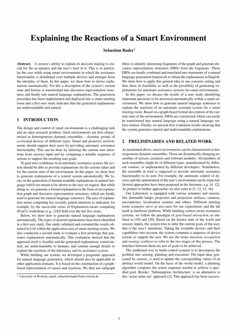
Explaining the Reactions of a Smart EnvironmentSebastian Bader1
Abstract. A system’s ability to explain its decision making is cru-cial for the acceptance and the user’s trust in it. This is in particu-lar the case while using smart environments in which the assistancefunctionality is distributed over multiple devices and emerges fromthe interplay of them. In this paper, we show how to derive expla-nations automatically. For this a description of the system’s currentstate and history is transformed into discourse representation struc-tures and finally into natural language explanations. The generationprocedure has been implemented and deployed into a smart meetingroom and a first user study indicates that the generated explanationsare understandable and natural.
1 INTRODUCTION
The design and control of smart environments is a challenging taskand an open research problem. Such environments are best charac-terised as heterogeneous dynamic ensembles – dynamic groups ofco-located devices of different types. Smart and proactive environ-ments should support their users by providing automatic assistancefunctionality. This can be done by inferring the current user inten-tions from sensory input and by computing a suitable sequence ofactions to support the resulting user goals.
To gain user confidence in an automatic assistance system, the sys-tem should be able to provide explanations for the actions taken andfor the current state of the environment. In this paper, we show howto generate explanations of a control system automatically. We fo-cus on the generation of human readable explanations in natural lan-guage which are meant to be shown to the user on request. But whiledoing so, we generate a formal explanation in the form of an explana-tion graph and discourse representation structures, which are finallyused to generate the natural language sentences. The area of explana-tion aware computing has recently gained attention as indicated, forexample, by the successful series of Explanation-aware computing(ExaCt) workshops (e.g., [18]) held over the last five years.
Below, we show how to generate natural language explanationsautomatically. The types of desired explanations have been identifiedin a first user study. Our study validated and extended the results ob-tained in [14] within the application area of smart meeting rooms. Wealso conducted a second study to evaluate a first prototype that gen-erates explanations automatically. This evaluation showed that theapproach itself is feasible and the generated explanations sound nat-ural, are understandable to humans, and contain enough details toexplain the reactions of the laboratory and its assistance system.
While building our system, we developed a pragmatic approachfor natural language generation, which should also be applicable inother application domains. It is based on the construction of a graph-based representation of causes and reactions. We then use subgraph
1 University of Rostock, email: [email protected]
filters to identify interesting fragments of the graph and generate dis-course representation structures (DRS) from the fragments. ThoseDRSs are finally combined and translated into statements of a naturallanguage generation framework to obtain the explanations in English.We show how to apply this general idea in one concrete setting andthus show its feasibility as well as the possibility of generating ex-planations for automatic assistance systems for smart environments.
In this paper, we discuss the results of a user study identifyingimportant questions to be answered automatically within a smart en-vironment. We show how to generate natural language sentences toexplain the reactions of an automatic assistant system for a smartmeeting room. Based on a graph-based formal description of the cur-rent state of the environment, DRSs are constructed which can easilybe transformed into natural language using a natural language sur-face realiser. Finally, we present first evaluation results showing thatthe system generates natural and understandable explanations.
2 PRELIMINARIES AND RELATED WORK
As mentioned above, smart environments can be characterised as het-erogeneous dynamic ensembles. Those are dynamically changing en-sembles of sensors, actuators and software modules. All members ofsuch ensembles might be of different types, manufactured by differ-ent vendors, or implemented by different developers. Nonetheless,the ensemble in total is supposed to provide automatic assistancefunctionality to its user. For example, the automatic control of de-vices and the optimisation of the user’s environment can be expected.Several approaches have been proposed in the literature, e.g. [4, 12].As pointer to further approaches we also refer to [3, 12, 15, 16].
Our Laboratory is equipped with various actuators and sensors,like dimmable lamps, projectors and projection surfaces, cameras,microphones, localisation systems and others. Different meetingroom scenarios serve as use-cases for our experiments and the labitself as hardware platform. While building context aware assistancesystems, we follow the paradigm of goal-based interaction, as out-lined in [10] and [20]. Based on the known state of the world andsensory inputs, the system tries to infer the current goals of the user,that is the user’s intentions. Taking the available devices and theircapabilities into account, the system computes a sequence of deviceactions to support the user. We use the terms intention recognitionand strategy synthesis to refer to the two stages of this process. Theinterface between them are sets of goals to be achieved.
The traditional way to build control systems is to decompose theproblem into sensing, planning and execution. The input data, gen-erated by sensors, is used to update the corresponding values of anabstract world model. On the basis of the world model, a planningalgorithm computes the action sequence needed to achieve a spec-ified goal. Brooks’ ‘Subsumption Architecture’ is an alternative tothis ‘sense–plan–act’ approach [2]. This approach has been success-
1
fully applied in various areas of robotics. Brooks’ ideas and his con-trol system inspired other researchers. The goalaviour-based system[1] described below implements such a behaviour-based approach tocontrol a smart environment in a distributed manner.
Research on intelligibility is concerned with the automatic gen-eration of explanations. An explanation is a sequence of statementsdescribing the current state or behaviour of a system and which clar-ifies the underlying causes, the context, and the consequences. It in-cludes a system’s ability to explain its own reactions, its internal stateand the implemented functionality. As pointed out by Dey in [5], itis one of the big challenges for the near future of ubiquitous com-puting. The required technology to build intelligent environments isavailable (in principle), but approaches to explain the reactions andbehaviour are still under research [13]. In particular, while consid-ering dynamic and heterogeneous device ensembles, it is yet com-pletely unclear how to design appropriate user interfaces and how toconstruct human readable explanations automatically. Nonetheless,providing explanations is necessary to gain the trust of the users intothe assistance provided by the system.
Automatic assistance systems need to make their decision basedon the perceived context. But, because neither the context, nor theinternal rules of the systems are accessible by the user, the systemitself appears as a black box. To provide insights into the systems in-ternals, explanations are needed to describe why certain actions aretaken, or why certain actions are not taken. In principle, two types ofexplanations can be distinguished: those meant for automatic analy-sis and those meant for humans. The first type is needed if the expla-nations of one system need to be forwarded to a second one. Here weconcentrate on explanations which are generated in natural languageand are meant for human users. In Section 3.2 we discuss a set ofquestions and show how to answer those questions automatically.
Natural language generation (NLG) is concerned with the gen-eration of natural language from a formal representation. Severalapproaches have been proposed in the past. A fairly up-to-dateoverview can be found on the website of the Special Interest Groupon Natural Language Generation (SIGGEN). NLG systems are usu-ally constructed in layers [17]: Layer 1 (Document planner) deter-mines the content and the structure of the document to convey thecommunicative goal. Layer 2 (Micro-planner) performs the lexical-isation, referencing and aggregation of paragraphs and sentences.Layer 3 (Surface realiser) applies grammar rules to convert an ab-stract representation into text. In our system described below, thedocument- and part of the micro-planning is done by the explana-tion generation process. As surface realiser, we use the SimpleNLGframework [8], which is also able to perform some micro-planning(in particular the aggregation), provides a lexicon with a fair cover-age of English words and performs the morphological realisation.
Discourse representation theory (DRT) provides an abstract andformal representation of meaning in natural language and allowsto handle references within and across sentences [11]. It em-ploys so-called discourse representation structures (DRS) to rep-resent the meaning of sentences. Without going into details, wepresent a slightly adapted example taken from [11]: The mean-ing of the sentences “Jones owns Ulysses. It fascinates him.” isrepresented within the following DRS: [X,Y] : [jones(X),ulysses(Y), owns(X,Y), fascinates(Y,X)]. A DRSconsists of two parts, a list of referents and a list of conditions. Thosedata structures can be used in natural language understanding and in-terpretation as well as for the generation of natural language. Forexample the Attempto Controlled English (ACE) project uses similarstructures to interpret and construct natural language sentences [7].
3 EXPLAINING A RULE-BASED CONTROLSYSTEM
After introducing our goalaviour-based control system, we discusshow to explain its reactions. The explanation generation describedbelow has been implemented in SWI-Prolog2 and the output is gen-erated in HTML to be easily presentable to the user. The results arediscussed in Section 3.7. After describing a rule- and goal-based con-troller, we discuss necessary explanation types and show how to an-swer certain questions automatically.3
3.1 Goal- and Rule-based ControlThe paradigm of goalaviour-based control was introduced in [1]. Asin Brooks original idea, the control system is implemented withinsmall independent behaviours. But instead of controlling the actua-tors of the environment directly, those behaviours produce goals4 –describing the desired (partial) state of the world. All goal-emittingbehaviours create their output solely based on the current state of theworld, and are independent of each other. The goals are merged and asequence of device actions is computed that leads to the desired stateof the world.
Example 1 One goalaviour could emit the goal to turn on a lampwhenever a user is close to it. Another goalaviour could emit the goalto turn off all lamps to save energy. In combination, both goalavioursresult in some kind of intelligent light control in which the user’sposition is illuminated and other lights are turned off to save energy.
Here, we consider crisp context information only. That is, the stateof every entity in the world (physical device, user or software com-ponent) can be described as a mapping from properties to values. Tosimplify the notation we use a set-based representation containingentity–property–value triples (EPVs). The state of the world is de-scribed as a consistent set of such triples. A set s is called consistentif and only if for every entity–property pair (e, p) there is at mostone entry (e, p, x) ∈ s. We use W to denote the set of all consistentworld states. To express a certain goal to be achieved by the con-troller, partial world states are used as customary in the automaticplanning community [9, 19]. Thus, a desired state of the world is de-scribed by the corresponding set of entity–property–value triples. Weuse G to refer to the set of all possible goals.
Example 2 Let l be a lamp, which can be switched on and off andalso be dimmed, with a dim-value of 1 indicating full brightness.The formalisation of the goal to switch on the lamp and turn it to fullbrightness is:5 {(l, on,>), (l, dim, 1)}.
Every goal represents a partial state of the world which has to beachieved. A goalaviour g maps the current state of the world to a setof goals: g : W → P(G). In contrast to the original idea, we restrictgoalaviours below to be precondition–goal rules. In particular, weconsider the precondition to be a set of entity–property–value triplesand the rules to be expressed as follows: Let {p1, p2, . . . , pn} ∈W be a set of preconditions and let {g1, g2, . . . , gm} ∈ G bea goal. Then the corresponding rule is expressed using the pair:〈{p1, p2, . . . , pn}, {g1, g2, . . . , gm}〉.2 See http://www.swi-prolog.org3 Please note that all examples described below have been simplified to show
the most important issues only, and might thus appear sometimes over-simplistic. In particular we assume that there is only one room involved.
4 Therefore they have been called goalaviours – goal-producing behaviours.5 We use > and ⊥ to denote the truth values true and false, respectively.
2
Example 3 The goalaviour IlluminateUser tries to set a lamp lto full brightness whenever a user u is at the lamp’s position:〈{(u, at-position, l)}, {(l, dim, 1.0)}〉. A second goalaviour, calledIlluminateRoom, tries to set the dim-value of all lamps to 0.5 to il-luminate the room slightly, whenever a user is present in the room:〈{(u, at-position, ?)}, {(l, dim, 0.5)}〉.6
Obviously, the two goalaviours described in Example 1 contra-dict each other. To solve such conflicts, a priority is attached to thegoalaviours. Every device filters the goals with respect to the pri-ority of the emitting goalaviour and selects only those with highestpriority. In addition, so-called merge-functions are attached to everyproperty, which are used to merge a set of values into a single one.All goals for one property are merged to obtain the final goal. Let pbe some property of a given entity and let Dp be the domain of itsvalues. A merge-function fp attached to p is a function from a setvalues to a single value: fp : P(Dp) → Dp.
Example 4 Below we use the logical disjunction to merge the powerstatus of a lamp and the average for the dim-value. Merging the out-put of the two goalaviours from Example 3 yields a value of 0.75 forthe dim-value of the lamp next to a user.
After filtering and merging the goals for a given entity of the en-semble, this entity is supposed to achieve the desired state. This canbe done by attaching simple planners to it, which are parametrisedwith a formal description of all available methods. Based on the cur-rent state of the entity, the desired goal state and the available meth-ods, the planner computes a sequence of actions to be performed toachieve the goal. As mentioned above, further details including a dis-cussion of consistency can be found in [1].
3.2 Explanation Types in Smart EnvironmentsAs mentioned above, different types of questions to be answered havebeen identified in the literature [14]. To validate them for our setting,a user study has been conducted to evaluate different automatic con-trol systems and to identify desired types of explanations [6]. Thesubjects (23 in total) have been asked to perform a number of taskswhile being supported by our systems. While going through threeincreasingly complex scenarios (simple lab usage, team discussion,lecture with students and multiple projectors), the lightening condi-tions, projectors and surfaces were controlled automatically. About90% of the participants explicitly stated that they liked the automaticassistance provided by our systems.
In addition to evaluating the automatic assistance, the users havebeen asked to write down all remarks and questions that came to theirmind. While performing the experiment, the users asked for the fol-lowing information: ‘Why has my output been put to projection sur-face X?’, ‘Will there be some reaction? If yes, when will that be?’,‘Why has the lamp X been dimmed?’, ‘Why has the projector notbeen turned off (yet)?’, ‘Why was the output of laptop X not movedto surface Y?’, and ‘What happens next?’. In addition to the ‘Why ...’and ‘Why not ...’ questions identified in [14] and discussed in Sec-tion 2, the users asked for timing information in form of ‘When ...’and ‘Why not ... yet?’ questions. This is of importance in such anenvironment, because some actions are time-dependent. For exam-ple, projectors should not be turned on and off repeatedly, but onlyafter being idle for a certain time interval. Below we discuss how togenerate the answers to some of those questions automatically.
6 Having a position implies to be within the room.
(lamp1, dim, 0.75)
MergerAverage
GoalaviourilluminateUser(Alice)
GoalaviourilluminageRoom
lamp1 is dimmed to 75%
illuminate the whole room slightlyilluminate the position
of Alice
(lamp1, dim, 1.0) (lamp1, dim, 0.5)
(Alice, atPosition, lamp1) Alice is near lamp1
lamp1 is dimmed to 50%
lamp1 is dimmed to 100%
Actiondim(lamp1, 0.75)
is effect of
tries totries
to
dim lamp1 to 75%
requested by requested
by
merged
using
rece
ive in
put
from
receive input
from
has
precondition
has
prec
ondit
ion
Figure 1. Explanation graph for the dim-value of lamp1. The grey boxesare not part of the specification but contain comments.
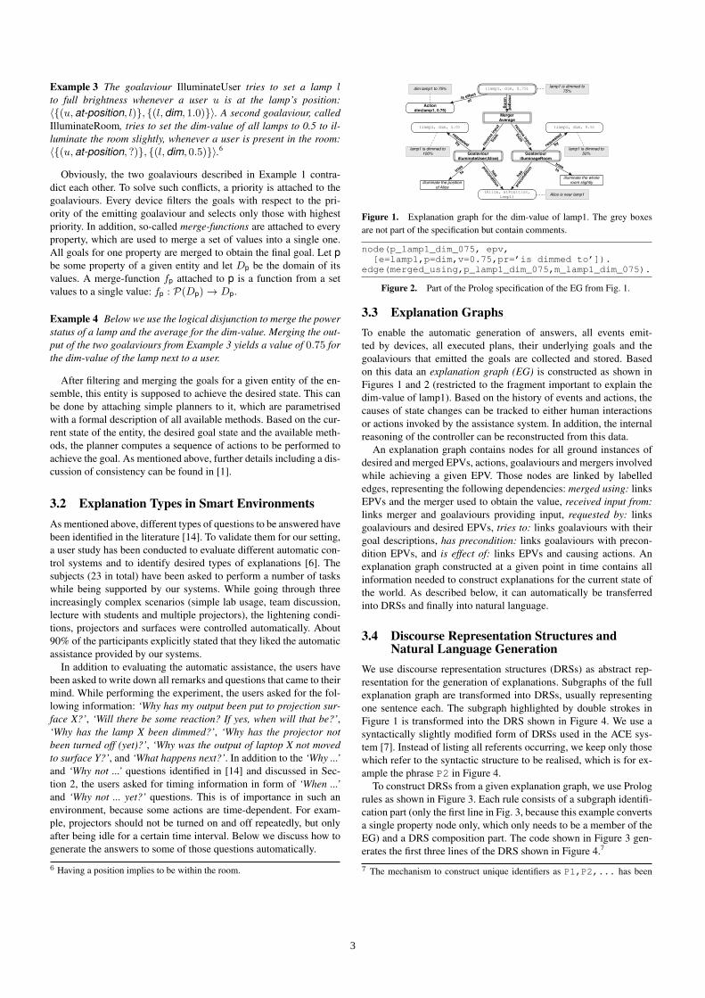
node(p_lamp1_dim_075, epv,[e=lamp1,p=dim,v=0.75,pr=’is dimmed to’]).
edge(merged_using,p_lamp1_dim_075,m_lamp1_dim_075).
Figure 2. Part of the Prolog specification of the EG from Fig. 1.
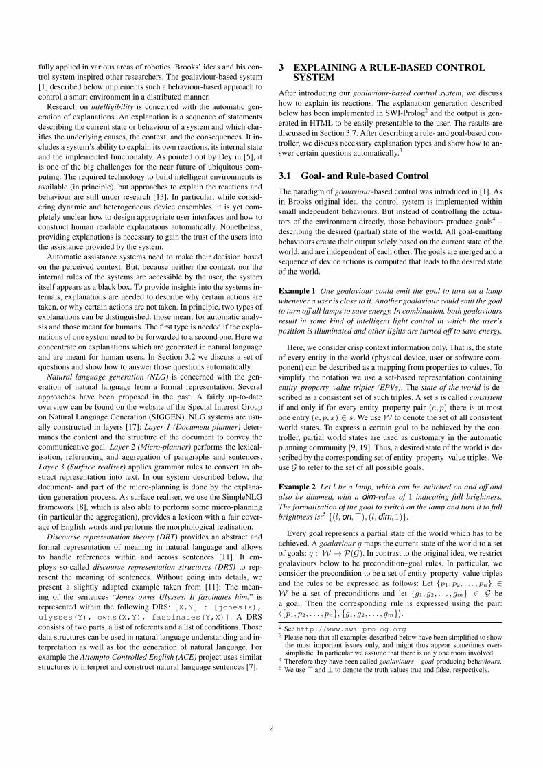
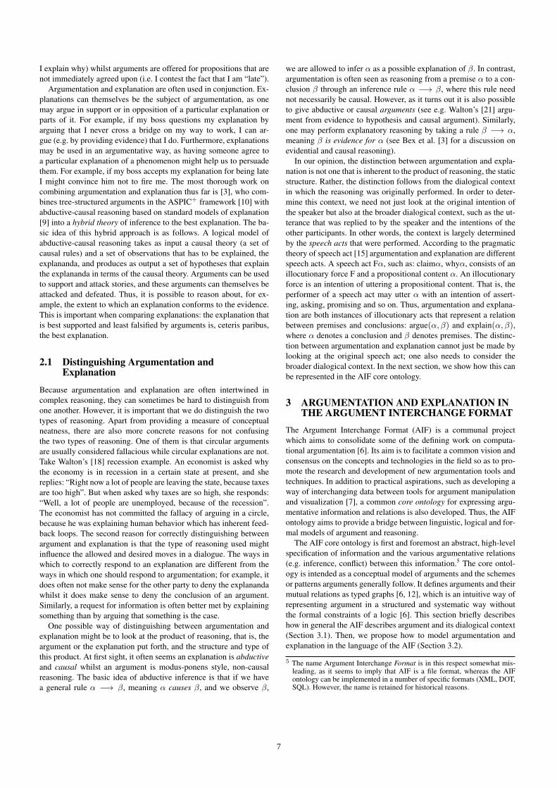
3.3 Explanation GraphsTo enable the automatic generation of answers, all events emit-ted by devices, all executed plans, their underlying goals and thegoalaviours that emitted the goals are collected and stored. Basedon this data an explanation graph (EG) is constructed as shown inFigures 1 and 2 (restricted to the fragment important to explain thedim-value of lamp1). Based on the history of events and actions, thecauses of state changes can be tracked to either human interactionsor actions invoked by the assistance system. In addition, the internalreasoning of the controller can be reconstructed from this data.
An explanation graph contains nodes for all ground instances ofdesired and merged EPVs, actions, goalaviours and mergers involvedwhile achieving a given EPV. Those nodes are linked by labellededges, representing the following dependencies: merged using: linksEPVs and the merger used to obtain the value, received input from:links merger and goalaviours providing input, requested by: linksgoalaviours and desired EPVs, tries to: links goalaviours with theirgoal descriptions, has precondition: links goalaviours with precon-dition EPVs, and is effect of: links EPVs and causing actions. Anexplanation graph constructed at a given point in time contains allinformation needed to construct explanations for the current state ofthe world. As described below, it can automatically be transferredinto DRSs and finally into natural language.
3.4 Discourse Representation Structures andNatural Language Generation
We use discourse representation structures (DRSs) as abstract rep-resentation for the generation of explanations. Subgraphs of the fullexplanation graph are transformed into DRSs, usually representingone sentence each. The subgraph highlighted by double strokes inFigure 1 is transformed into the DRS shown in Figure 4. We use asyntactically slightly modified form of DRSs used in the ACE sys-tem [7]. Instead of listing all referents occurring, we keep only thosewhich refer to the syntactic structure to be realised, which is for ex-ample the phrase P2 in Figure 4.
To construct DRSs from a given explanation graph, we use Prologrules as shown in Figure 3. Each rule consists of a subgraph identifi-cation part (only the first line in Fig. 3, because this example convertsa single property node only, which only needs to be a member of theEG) and a DRS composition part. The code shown in Figure 3 gen-erates the first three lines of the DRS shown in Figure 4.7
7 The mechanism to construct unique identifiers as P1,P2,... has been
3
drs(EG, [PS]:Conditions) :- % EG to one DRSmember(node(ID,epv,NC), EG),% identify subgraphmembers([e=E,v=V,pr=Pr],NC),% access node contentConditions = [E=object(E), % construct objectV=object(V), % construct verbPS=predicate(E, Pr, V), % construct predicatefeature(PS,’Feature.TENSE’,’Tense.PAST’)]).
Figure 3. Prolog code to transform parts of an EG into a DRS.
[P2]:[P1=object(lamp1), P3=object(0.75),P2=predicate(P1,’is dimmed to’,P3),feature(P2,’Feature.TENSE’,’Tense.PAST’)])G1=object(’IlluminateUser(Alice)’),G2=object(’IlluminateRoom’),GS1=conjunction([G1,G2]), M1=modifier(P2,by,GS1)]
Figure 4. DRS for the subgraph highlighted by double strokes in Fig. 1.
To actually generate explanations in natural language, we rely onthe SimpleNLG toolkit developed at the University of Aberdeen[8]. The toolkit is a realiser which allows to generate correct En-glish sentences based on an abstract representation. Based on theDRSs constructed above SimpleNLG code is constructed automat-ically. For this we adapted the syntax of the DRSs slightly. Insteadof writing object(P1,lamp1) we use P1=object(lamp1)to indicate that this should be transformed into an object creationstatement within the SimpleNLG framework. This notation allowsto sort all conditions specified within a DRS such that in theright hand side only initialised objects occur. That is the conditionP2=predicate(P1,’is dimmed to’,P3) should be evalu-ated only after evaluating the conditions defining P1 and P3, as itrefers to them. After sorting the conditions, they are transformedinto SimpleNLG statements as shown in Figure 5. Executing thatcode results in the string “lamp1 was dimmed to 0.75 by Illumina-teUser(Alice) and IlluminateRoom”. As mentioned above, the exam-ple has been simplified to show the key ideas here. The completedescription is shown below.
3.5 Answering Why QuestionsBased on the full explanation graph constructed above, why ques-tions can be answered as follows. The system shows a list of entity–property–value triples to the user. This list is generated from nodesin the explanation graph representing EPVs not updated later, thatis only those nodes corresponding to entity–property–value triples(e, p, v1) such that there is no edge coming from a node (e, p, v2).In our running example, the list includes the triples (lamp1, on,>),(lamp2, on,>), (lamp1, dim, 0.75) and (lamp2, dim, 0.5). Start-ing from the selected triple, the graph is traversed following the out-going edges. Figure 1 shows the subgraph obtained for the dim-value of lamp1, that is starting from the node corresponding to(lamp1, dim, 0.75). Once the subgraph is obtained, DRSs are gen-erated as described above. Finally, every DRS is transformed intonatural language using SimpleNLG.
Example 5 After running the controller and the two goalavioursdescribed in Example 3, the lamp1 (which is next to user Alice) isdimmed to 0.75. For this, the following explanation is generated:
“The dim-value of lamp1 was set to 0.75, because thegoalaviours IlluminateUser(Alice) and IlluminateRoom are ac-tive. The goalaviour IlluminateUser(Alice) tries to illuminate the
omitted here, it is based on the gensym feature of SWI-Prolog.
P1 = createNounPhrase("lamp1");P3 = createNounPhrase("0.75");P2 = createClause(P1, "is dimmed to", P3);P2.setFeature(Feature.TENSE, Tense.PAST);G1 = createNounPhrase("IlluminateUser(Alice)");G2 = createNounPhrase("IlluminateRoom");GS1 = new CoordinatedPhraseElement(G1,G2);P2.addModifier(createPrepositionPhrase("by", GS1));return realiser.realise(P2);
Figure 5. Part of the SimpleNLG Java code obtained for the DRS in Fig. 4.
position of Alice. Setting the dim-value of lamp1 to 1.0 is a directgoal of IlluminateUser(Alice). The goalaviour IlluminateRoomtries to illuminate the full room slightly. Setting the dim-value oflamp1 to 0.5 is a direct goal of IlluminateRoom. The goalavioursare merged using the average. The dim-value of lamp1 has beenset to 0.75 while performing action lamp1:dim(0.75). Thegoalaviour IlluminateUser(Alice) was activated because Alice isat position lamp1. The goalaviour IlluminateRoom was activatedbecause Alice is at position lamp1.”
3.6 Answering Why-not and other QuestionsWhy-not questions can be answered similarly. But instead of findingthe goalaviours which have been active, we need to determine thosewhich might have led to the questioned state of the world. In princi-ple, three cases can be distinguished: (1) A corresponding goalaviourhas been active, but has been overwritten by another goalaviour withhigher priority. (2) A corresponding goalaviour has been active, butthe merging changed the result. (3) No corresponding goalaviour hasbeen active. Generating explanations for the first two cases can bedone similar to the generation for why-questions described above.
Example 6 An automatic response to “Why has lamp1 not beendimmed to 1.0?” (case 2 above) is:
“The dim-value of lamp1 was set to 0.75, because the out-puts of the goalaviours IlluminateUser(Alice) and Illuminate-Room were merged using the average. The goalaviour Illumi-nateUser(Alice) tries to illuminate the position of Alice. Set-ting the dim-value of lamp1 to 1.0 is a direct goal of Illumina-teUser(Alice). The goalaviour IlluminateRoom tries to illuminatethe full room slightly. Setting the dim-value of lamp1 to 0.5 is adirect goal of IlluminateRoom.
In case 3, we first need to identify potential goalaviours whichcould lead to the questioned state, but have not been active. Then, themissing preconditions need to be identified and explanations have tobe generated describing how to make those preconditions true.
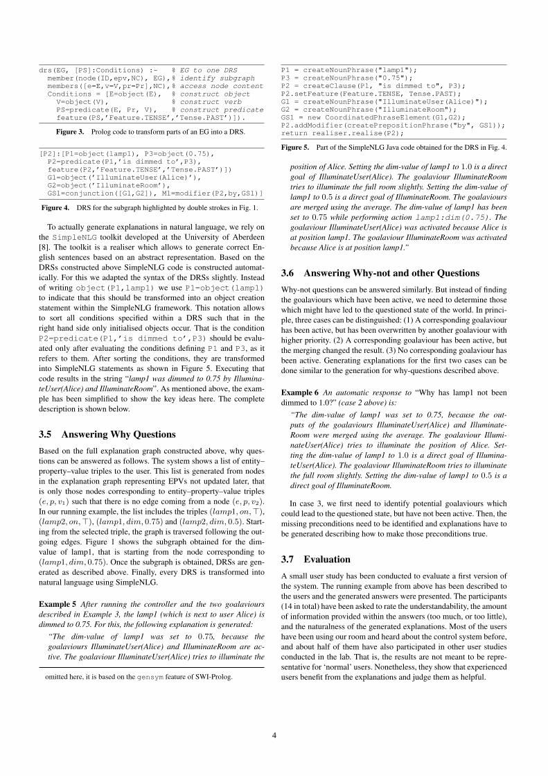
3.7 EvaluationA small user study has been conducted to evaluate a first version ofthe system. The running example from above has been described tothe users and the generated answers were presented. The participants(14 in total) have been asked to rate the understandability, the amountof information provided within the answers (too much, or too little),and the naturalness of the generated explanations. Most of the usershave been using our room and heard about the control system before,and about half of them have also participated in other user studiesconducted in the lab. That is, the results are not meant to be repre-sentative for ‘normal’ users. Nonetheless, they show that experiencedusers benefit from the explanations and judge them as helpful.
4
●●●
●
a b c d
01
23
4
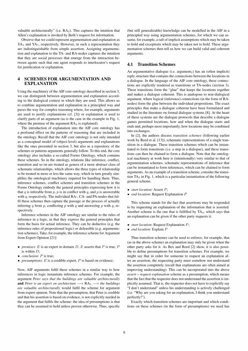
Figure 6. Results of the evaluation of a first prototype depicted as box plot,showing the median (line), the lower and upper quantile (box), and outliers.
Figure 6 shows a summary of the results. All users have been askedto answer the following questions: (a) ‘Are the answers understand-able?’, (b) ‘Do the answers contain enough details?’, (c) ‘Do the an-swers contain too much details?’ and (d) ‘Do the explanations soundnatural?’ on a Likert scale ranging from 4 = ‘yes completely’, 3 =‘yes’, 2 = ‘more or less’, 1 = ‘no’, 0 = ‘not at all’. The users con-sidered the answers to be understandable, to sound natural and tocontain (more or less) the right amount of detail. In addition to an-swering the questions listed in the table, the users were asked to listmissing information. Most of the participants asked for informationon the merging policy used to combine the outputs of the differentsentences. This information (as contained in Examples 5 and 6) wasnot yet included in the tested prototype, but added later.
4 CONCLUSIONS AND FUTURE WORKWe showed how to generate explanations for the actions taken by anautomatic assistance system for smart environments. The system’sability to explain its behaviour and internal decision making is cru-cial for the acceptance and the users trust in it. The explanation gen-eration has been implemented for a distributed control system pro-viding assistance in a smart meeting room. We showed how to gen-erate human readable explanations for the overall behaviour of sucha system. In particular, we discussed how to answer why and why-not questions. To the best of our knowledge, there is no such systemwhich is able to support users in some real environment and to ex-plain its actions and the current state of the world in human readablenatural language.
The system employs an explanation graph to represent the historyof the system and to identify underlying causes. Based on that, dis-course representation structures are constructed. Those structures arelater transformed into natural language sentences using a surface re-aliser for English. The whole explanation generation has been imple-mented in Prolog. A small user study has been conducted to evaluatethe explanations. The users rated the explanations to be both under-standable and natural.
The system, as discussed above, demonstrates the general feasibil-ity of an automatic generation of natural language explanations forthe reactions of smart environments. Nonetheless there are open is-sues to be addressed in the near future. The explanations generatedfor why-not questions are so far quite general, because sometimesit is hard to detect the correct preconditions needed to explain whysomething did not happen, or has not been achieved. Here ideas fromthe area of abduction may help to provide better explanations.
We furthermore need to extend the approach to allow chainingof explanations. The presented approach, based on the explanationgraph and the DRSs, is powerful enough, but we need to investigatewhere to stop while identifying the true reasons, because so far only‘level 2’ explanations are generated. This needs to be explored in a
larger user study. In addition to evaluating the questions and answers,we plan to explore suitable user interfaces including speech interac-tions. Another open issue is the fine-tuning of the micro-planning forthe language generation. In particular cross sentence references needto be included to make the explanations even more natural.
Finally, we plan to extend the approach to a probabilistic setting.This is necessary due to the inherent probabilistic nature of such en-vironments. Most actions are taken based on probabilistic reasoning,which needs to be integrated into the generated explanations. Andas pointed out in [13] the acceptance of explanations depends on thecertainty with which they are derived.
AcknowledgmentThe author has been supported by DFG graduate school 1424MuSAMA at the University of Rostock, Germany and would liketo thank three anonymous reviewers for their comments.
REFERENCES[1] S. Bader and M. Dyrba, ‘Goalaviour-based control of heterogeneous
and distributed smart environments’, in Proceedings of IE’11, pp. 142–148. IEEE, (2011).
[2] R. A. Brooks, ‘A robust layered control system for a mobile robot’,IEEE Journal of Robotics and Automation, RA-2(1), 14–23, (1986).
[3] D. J. Cook and S. K. Das, Smart Environments, Wiley, 2005.[4] D. J. Cook, M. Huber, D. Gopalratnam, and M. Youngblood, ‘Learn-
ing to control a smart home environment’, Innovative Applications ofArtificial Intelligence, (2003).
[5] A. K. Dey, ‘Modeling and intelligibility in ambient environments’, J.Ambient Intell. Smart Environ., 1, 57–62, (2009).
[6] M. Dyrba, R. Nicolay, S. Bader, and T. Kirste, ‘Evaluation of two con-trol systems for smart environments’, in Proceedings of CoSDEO atMobiquitous 2011, (2011).
[7] N. E. Fuchs, U. Schwertel, and R. Schwitter, ‘Attempto controlled en-glish - not just another logic specification language’, in Logic-BasedProgram Synthesis and Transformation, ed., P. Flener, number 1559 inLNCS. 8th International Workshop LOPSTR’98, Springer, (1999).
[8] A. Gatt and E. Reiter, ‘Simplenlg: A realisation engine for practicalapplications’, in Proceedings of ENLG-2009, (2009).
[9] M. Ghallab, C. K. Isi, S. Penberthy, D. E. Smith, Y. Sun, and D. Weld,‘PDDL - The Planning Domain Definition Language’, Technical ReportCVC TR-98-003/DCS TR-1165, Yale Center for Computational Visionand Control, (1998).
[10] T. Heider and T. Kirste, ‘Supporting goal-based interaction with dy-namic intelligent environments’, in Proceedings of ECAI 2002, pp.596–600, (2002).
[11] H. Kamp and U. Reyle, From Discourse to Logic, Kluwer, 1993.[12] J. A. Kientz, S. N. Patel, B. Jones, E. Price, E. D. Mynatt, and Gre-
gory D. Abowd, ‘The georgia tech aware home’, in CHI ’08 ExtendedAbstracts on Human Factors in Computing Systems, pp. 3675–3680.ACM, (2008).
[13] B. Y. Lim and A. K. Dey, ‘Design of an intelligible mobile context-aware application’, in MobileHCI ’11, pp. 157–166. ACM, (2011).
[14] B. Y. Lim, A. K. Dey, and D. Avrahami, ‘Why and why not explana-tions improve the intelligibility of context-aware intelligent systems’,in Proceedings of the 27th international conference on Human factorsin computing systems, CHI ’09, pp. 2119–2128. ACM, (2009).
[15] Handbook of Ambient Intelligence and Smart Environments, eds.,H. Nakashima, H. Aghajan, and J. C. Augusto, Springer, 2010.
[16] S. Poslad, Ubiquitous Computing: Smart Devices, Environments andInteractions, Wiley, 2009.
[17] E. Reiter and R. Dale, Building Natural Language Generation Systems,Studies in natural language processing, Cambridge Press, 2000.
[18] Thomas Roth-Berghofer, Nava Tintarev, and David B. Leake, eds. Pro-ceedings of Explanation-aware Computing Exact 2011, 2011.
[19] S. Russell and P. Norvig, Artificial Intelligence: A Modern Approach,Prentice Hall, 2 edn., 2003.
[20] U. Saif, H. Pham, J. M. Paluska, J. Waterman, C. Terman, and S. Ward,‘A case for goal-oriented programming semantics’, in Proceedings ofUbiSys at UbiComp 2003, (2003).
5
Argumentation and explanation in the context of dialogueFloris Bex1 and Katarzyna Budzynska2 and Douglas Walton 3
Abstract. Whilst computational argumentation and explanationhave both been studied intensively in AI, models that incorporateboth types of reasoning are few and far between. The two forms ofreasoning need to be clearly distinguished, as they may influence di-alogue protocol and strategy. Using the language of the ArgumentInterchange Format, we show that the distinction can be made byconsidering the speech acts used in a dialogue, and explore some ofthe implications of the combination of argument and explanation.
1 INTRODUCTIONReasoning can be characterized as the process of moving from cer-tain starting statements, assumptions or premises, to other state-ments, conclusions [17]. At the same time, reasoning is also the out-come of this process (i.e. the product), a static structure. Reasoningis typically used in the context of argumentation, where premises areoffered as proof of a conclusion or a claim often in order to persuadesomeone or settle an issue. However, reasoning is also used in thecontext of explanation, where the explananda (facts to be explained)are explained by a coherent set of explanans (facts that explain). Theusual purpose of explanation is not to convince someone but ratherto help someone understand why the explananda are the case, thatis, to help the explainee understand something that she claims shedoes not now understand, or does not completely understand [19].In this paper, we aim to explore the similarities and differences be-tween argumentation and explanation and make a first step towardsan integrated computational model of the two.
Argumentation and explanation are well-presented in their respec-tive sub-fields of AI. Computational models of argumentation haveemerged and matured in the past twenty-or-so years [11]. Compu-tational models for explanation are mainly based on the techniqueof abductive (model-based) reasoning, and have been studied in thecontext of medical and system diagnosis and natural language under-standing (e.g. [4, 9, 5, 14]). Despite the important role explanationscan play in argumentative dialogue, there have not been many at-tempts to combine argumentation and explanation into one formalmodel. Perhaps the most thorough work thus far is by Bex et al. [3],who combine structured arguments with abductive-causal reasoninginto one model of inference to the best explanation. Other examplesof work in which argumentation and explanation are combined are[9, 16].
Argumentation and explanation are often used in concert whenperforming complex reasoning: the explanations can be the subject of
1 School of Computing, University of Dundee, Dundee, UK, DD1 4HN,email: [email protected]
2 Department of Logic and Cognitive Science, Institute of Philosophyand Sociology Polish Academy of Sciences, Poland email: [email protected]
3 Centre for Research in Reasoning, Argumentation and Rhetoric (CRRAR),University of Windsor, Canada email: [email protected]
argumentation or they may be used in an argumentative way. Hence,we need a model that integrates argumentation and explanation, inwhich the two types of reasoning are clearly distinguished; argumen-tation and explanation have different properties and the reasoningwith arguments and explanations adheres to different patterns.
In our opinion, the only way to distinguish between argumentationand explanation is by looking at the context in which the reasoningwas originally performed. In this paper, we concentrate on the con-textual property of the intention of the speaker. We are interested inhow to represent the connection between the intentions and the staticreasoning structure under consideration. In this paper, we show thatthis connection can be made by using ideas from speech act theory[15]. More specifically, we argue that it is the illocutionary force ofthe speech act in a dialogue that determines whether reasoning is ar-gumentation or explanation. We will use the conceptual model of theArgument Interchange Format [6, 13] so as to provide a model thatis not tied to any specific dialogue or argument formalism.
The rest of this paper is organized as follows. In section 2 we elab-orate on the (structural and contextual) similarities and differencesbetween argumentation and explanation and we give some examplesof both. Section 3 discusses our ideas for a framework for argumen-tation and explanation. Section 4 briefly explores the ramificationsof combining argumentation and explanation in one comprehensivemodel of dialogical reasoning, and section 5 concludes the paper.
2 ARGUMENTATION AND EXPLANATION
Argumentation is a type of reasoning used in a specific probativefunction, to prove a claim [17]. By its very nature, it involves somesort of opposition between parties4 and reasons are not just given tosupport a conclusion but also to remove an opponent’s doubts aboutthis conclusion. For example, a reasoning α ` β is argumentationwhen β is questioned (dubious) and a proponent of this argumentuses α not only to support β, but also to remove an opponent’s doubtsabout β. Explanation, on the other hand, has not as its main goal toprove but rather to explicate why something is the case. Explanationin its purest form is not inherently dialectical: an explanation is givento help the other party, not to convince them. Consider the followingexample. Say I arrive at work at ten in the morning and my boss askswhy I am late. I can either explain to him that the bridge was openand that I had to wait or I can argue that I am not “late”, because mycontract does not specify the exact hours I have to be at the office.In first case, I am answering my boss’ question by explaining to himwhat caused my being late. In the latter case, I am arguing against myboss claim that I am late. Thus, explanations are usually offered forpropositions that both parties agree on (i.e. we agree I am “late” and
4 Hence the use of the term “calculi of opposition” for argumentation-theoretic semantics that allow one to calculate the acceptability of argu-ments
6
I explain why) whilst arguments are offered for propositions that arenot immediately agreed upon (i.e. I contest the fact that I am “late”).
Argumentation and explanation are often used in conjunction. Ex-planations can themselves be the subject of argumentation, as onemay argue in support or in opposition of a particular explanation orparts of it. For example, if my boss questions my explanation byarguing that I never cross a bridge on my way to work, I can ar-gue (e.g. by providing evidence) that I do. Furthermore, explanationsmay be used in an argumentative way, as having someone agree toa particular explanation of a phenomenon might help us to persuadethem. For example, if my boss accepts my explanation for being lateI might convince him not to fire me. The most thorough work oncombining argumentation and explanation thus far is [3], who com-bines tree-structured arguments in the ASPIC+ framework [10] withabductive-causal reasoning based on standard models of explanation[9] into a hybrid theory of inference to the best explanation. The ba-sic idea of this hybrid approach is as follows. A logical model ofabductive-causal reasoning takes as input a causal theory (a set ofcausal rules) and a set of observations that has to be explained, theexplananda, and produces as output a set of hypotheses that explainthe explananda in terms of the causal theory. Arguments can be usedto support and attack stories, and these arguments can themselves beattacked and defeated. Thus, it is possible to reason about, for ex-ample, the extent to which an explanation conforms to the evidence.This is important when comparing explanations: the explanation thatis best supported and least falsified by arguments is, ceteris paribus,the best explanation.
2.1 Distinguishing Argumentation andExplanation
Because argumentation and explanation are often intertwined incomplex reasoning, they can sometimes be hard to distinguish fromone another. However, it is important that we do distinguish the twotypes of reasoning. Apart from providing a measure of conceptualneatness, there are also more concrete reasons for not confusingthe two types of reasoning. One of them is that circular argumentsare usually considered fallacious while circular explanations are not.Take Walton’s [18] recession example. An economist is asked whythe economy is in recession in a certain state at present, and shereplies: “Right now a lot of people are leaving the state, because taxesare too high”. But when asked why taxes are so high, she responds:“Well, a lot of people are unemployed, because of the recession”.The economist has not committed the fallacy of arguing in a circle,because he was explaining human behavior which has inherent feed-back loops. The second reason for correctly distinguishing betweenargument and explanation is that the type of reasoning used mightinfluence the allowed and desired moves in a dialogue. The ways inwhich to correctly respond to an explanation are different from theways in which one should respond to argumentation; for example, itdoes often not make sense for the other party to deny the explanandawhilst it does make sense to deny the conclusion of an argument.Similarly, a request for information is often better met by explainingsomething than by arguing that something is the case.
One possible way of distinguishing between argumentation andexplanation might be to look at the product of reasoning, that is, theargument or the explanation put forth, and the structure and type ofthis product. At first sight, it often seems an explanation is abductiveand causal whilst an argument is modus-ponens style, non-causalreasoning. The basic idea of abductive inference is that if we havea general rule α −→ β, meaning α causes β, and we observe β,
we are allowed to infer α as a possible explanation of β. In contrast,argumentation is often seen as reasoning from a premise α to a con-clusion β through an inference rule α −→ β, where this rule neednot necessarily be causal. However, as it turns out it is also possibleto give abductive or causal arguments (see e.g. Walton’s [21] argu-ment from evidence to hypothesis and causal argument). Similarly,one may perform explanatory reasoning by taking a rule β −→ α,meaning β is evidence for α (see Bex et al. [3] for a discussion onevidential and causal reasoning).
In our opinion, the distinction between argumentation and expla-nation is not one that is inherent to the product of reasoning, the staticstructure. Rather, the distinction follows from the dialogical contextin which the reasoning was originally performed. In order to deter-mine this context, we need not just look at the original intention ofthe speaker but also at the broader dialogical context, such as the ut-terance that was replied to by the speaker and the intentions of theother participants. In other words, the context is largely determinedby the speech acts that were performed. According to the pragmatictheory of speech act [15] argumentation and explanation are differentspeech acts. A speech act Fα, such as: claimα, whyα, consists of anillocutionary force F and a propositional content α. An illocutionaryforce is an intention of uttering a propositional content. That is, theperformer of a speech act may utter α with an intention of assert-ing, asking, promising and so on. Thus, argumentation and explana-tion are both instances of illocutionary acts that represent a relationbetween premises and conclusions: argue(α, β) and explain(α, β),where α denotes a conclusion and β denotes premises. The distinc-tion between argumentation and explanation cannot just be made bylooking at the original speech act; one also needs to consider thebroader dialogical context. In the next section, we show how this canbe represented in the AIF core ontology.
3 ARGUMENTATION AND EXPLANATION INTHE ARGUMENT INTERCHANGE FORMAT
The Argument Interchange Format (AIF) is a communal projectwhich aims to consolidate some of the defining work on computa-tional argumentation [6]. Its aim is to facilitate a common vision andconsensus on the concepts and technologies in the field so as to pro-mote the research and development of new argumentation tools andtechniques. In addition to practical aspirations, such as developing away of interchanging data between tools for argument manipulationand visualization [7], a common core ontology for expressing argu-mentative information and relations is also developed. Thus, the AIFontology aims to provide a bridge between linguistic, logical and for-mal models of argument and reasoning.
The AIF core ontology is first and foremost an abstract, high-levelspecification of information and the various argumentative relations(e.g. inference, conflict) between this information.5 The core ontol-ogy is intended as a conceptual model of arguments and the schemesor patterns arguments generally follow. It defines arguments and theirmutual relations as typed graphs [6, 12], which is an intuitive way ofrepresenting argument in a structured and systematic way withoutthe formal constraints of a logic [6]. This section briefly describeshow in general the AIF describes argument and its dialogical context(Section 3.1). Then, we propose how to model argumentation andexplanation in the language of the AIF (Section 3.2).
5 The name Argument Interchange Format is in this respect somewhat mis-leading, as it seems to imply that AIF is a file format, whereas the AIFontology can be implemented in a number of specific formats (XML, DOT,SQL). However, the name is retained for historical reasons.
7
3.1 The AIF Core OntologyThe AIF core ontology [6, 12] and its dialogical extension [13] al-lows for the explicit representation of both reasoning structure andthe context of dialogue in which it is put forth. More concretely, it en-ables to connect the locutions uttered during a dialogue (argument2)and the underlying arguments expressed by the content of those lo-cutions (argument1).
In the ontology, argument1 is represented by two kinds of nodes:
• information (I-) nodes, which refer to data, and• scheme (S-) nodes, which refer to the passage between informa-
tion nodes, which are classified into three groups:
– rule application (RA-) nodes which correspond to inference orsupport,
– conflict application (CA-) nodes which correspond to conflictor refutation,
– preference application (PA-) nodes which correspond to valuejudgements or preference orderings.
The argument2 is also described by two types of nodes:
• locution nodes (L-), which refer to utterances and constitute a sub-class of information nodes, and
• transition application (TA-) nodes, which refer to the passage be-tween locutions.
The TA-nodes are governed by the protocol of a dialogue system,recording e.g. that a given assertion has been made in response to anearlier question [13, 2].
The interaction between argument1 and argument2 is captured bymeans of two types of illocutionary application (YA-) nodes [13]:
• the YA-nodes between I-nodes and L-nodes, and• the YA-nodes between RA-nodes and TA-nodes.
For example, an YA-node may represent the relation between an as-sertion claimαwith its propositional content α. The YA-link is deter-mined and warranted (authorized) by the constitutive rules for speechacts [15]. These rules determine what constitutes a successful speechact. For example, an assertion may be unsuccessful and attacked, ifits performer did not have enough evidence for the statement or hedeclared what he actually disbelieves.
3.2 The Distinction between Argument andExplanation in AIF
In this section, we propose the specification of argumentation andexplanation in the AIF core ontology. We will illustrate it on the ex-ample adapted from Walton [18].
Allen The Evanston City Council should make it illegal to tear downthe citys old warehouses.
Beth Whats the justification for preserving them?Allen The warehouses are valuable architecturally.Beth Why are they so valuable?Allen The older buildings lend the town its distinctive character.
As is pointed out by Walton and Bex [20], Beth’s first questionclearly asks for an argument (a justification). Beth’s second questionis ambiguous: it could ask for either an argument or an explanation.This depends on whether Beth does not understand why the buildingsare valuable or whether Beth has doubts about the buildings’ value.
This in turn depends on Beth’s beliefs or commitments about ‘Thewarehouses are valuable architecturally’; if Beth believes or is openlycommitted to this proposition, we can assume that she is asking foran explanation, as there is no doubt. For our example, we assume thatBeth is asking for an explanation.
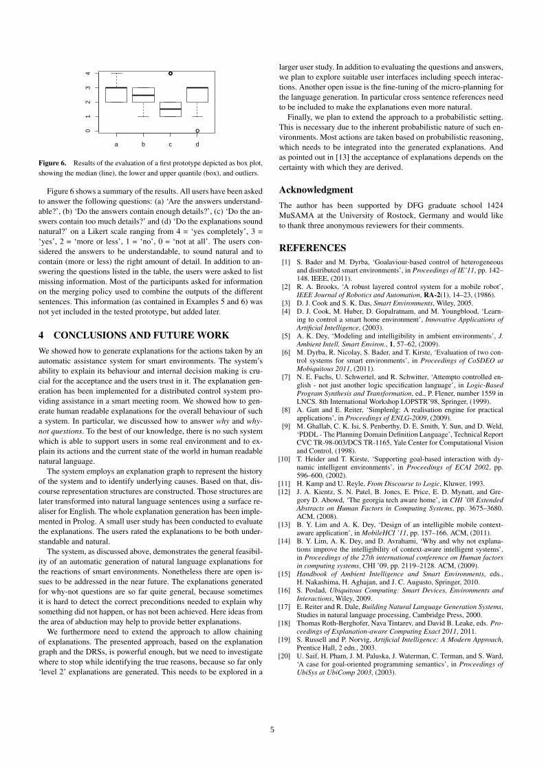
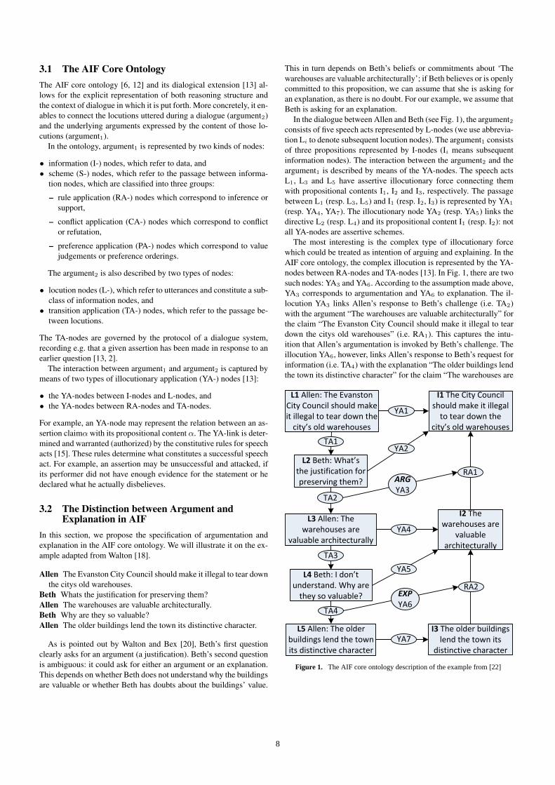
In the dialogue between Allen and Beth (see Fig. 1), the argument2consists of five speech acts represented by L-nodes (we use abbrevia-tion Li to denote subsequent locution nodes). The argument1 consistsof three propositions represented by I-nodes (Ii means subsequentinformation nodes). The interaction between the argument2 and theargument1 is described by means of the YA-nodes. The speech actsL1, L3 and L5 have assertive illocutionary force connecting themwith propositional contents I1, I2 and I3, respectively. The passagebetween L1 (resp. L3, L5) and I1 (resp. I2, I3) is represented by YA1
(resp. YA4, YA7). The illocutionary node YA2 (resp. YA5) links thedirective L2 (resp. L4) and its propositional content I1 (resp. I2): notall YA-nodes are assertive schemes.
The most interesting is the complex type of illocutionary forcewhich could be treated as intention of arguing and explaining. In theAIF core ontology, the complex illocution is represented by the YA-nodes between RA-nodes and TA-nodes [13]. In Fig. 1, there are twosuch nodes: YA3 and YA6. According to the assumption made above,YA3 corresponds to argumentation and YA6 to explanation. The il-locution YA3 links Allen’s response to Beth’s challenge (i.e. TA2)with the argument “The warehouses are valuable architecturally” forthe claim “The Evanston City Council should make it illegal to teardown the citys old warehouses” (i.e. RA1). This captures the intu-ition that Allen’s argumentation is invoked by Beth’s challenge. Theillocution YA6, however, links Allen’s response to Beth’s request forinformation (i.e. TA4) with the explanation “The older buildings lendthe town its distinctive character” for the claim “The warehouses are
L1 Allen: The Evanston City Council should make it illegal to tear down the
city’s old warehouses
L2 Beth: What’s the justification for preserving them?
L3 Allen: The warehouses are
valuable architecturally
L4 Beth: I don’t understand. Why are
they so valuable?
L5 Allen: The older buildings lend the town its distinctive character
I1 The City Council should make it illegal
to tear down the city’s old warehouses
I2 The warehouses are
valuable architecturally
I3 The older buildings lend the town its
distinctive character
TA1
TA4
TA3
TA2
RA1
RA2
YA1
YA2
YA4
ARGYA3
YA5
YA7
EXPYA6
Figure 1. The AIF core ontology description of the example from [22]
8
valuable architecturally” (i.e. RA2). This captures the intuition thatAllen’s explanation is invoked by Beth’s request for information.
Observe that we could represent argumentation and explanation asYA4 and YA7, respectively. However, in such a representation theyare indistinguishable from simple assertion. Assigning argumenta-tion and explanation to the TA- and RA-nodes captures the intuitionthat they are social processes that emerge from the interaction be-tween agents such that one agent responds to interlocutor’s requestfor justification or explanation.
4 SCHEMES FOR ARGUMENTATION ANDEXPLANATION
Using the machinery of the AIF core ontology described in section 3,we can distinguish between argumentation and explanation accord-ing to the dialogical context in which they are used. This allows usto combine argumentation and explanation in a principled way andpaves the way for complex reasoning where, for example, argumentsare used to justify explanations (cf. [3]) or explanation is used toclarify parts of an argument (as is the case in the example in Fig. 1,where the premise of the argument RA2 is explained).
The introduction of explanation into the AIF core ontology hasa profound effect on the patterns of reasoning that are included inthe ontology. Recall that the AIF core ontology is not only intendedas a conceptual model of (object-level) arguments and explanationslike the ones presented in section 3, but also as a repository of theschemes or patterns arguments generally follow. To this end, the coreontology also includes a so-called Forms Ontology, which containsthese schemes. So in the ontology, relations like inference, conflict,transition and so on are treated as genera of a more abstract class ofschematic relationships, which allows the three types of relationshipto be treated in more or less the same way, which in turn greatly sim-plifies the ontological machinery required for handling them. Thus,inference schemes, conflict schemes and transition schemes in theForms Ontology embody the general principles expressing how it isthat q is inferable from p, p is in conflict with q, and p is answerablewith q, respectively. The individual RA-, CA- and PA-nodes that ful-fil these schemes then capture the passage or the process of actuallyinferring q from p, conflicting p with q and answering p with q, re-spectively.
Inference schemes in the AIF ontology are similar to the rules ofinference in a logic, in that they express the general principles thatform the basis for actual inference. They can be deductive (e.g. theinference rules of propositional logic) or defeasible (e.g. argumenta-tion schemes). Take, for example, the inference scheme for Argumentfrom Expert Opinion [21]:
• premises: E is an expert in domain D, E asserts that P is true, Pis within D;
• conclusion: P is true;• presumptions: E is a credible expert, P is based on evidence;
Now, AIF arguments fulfil these schemes in a similar way to howinferences in logic instantiate inference schemes. For example, theargument Peter says that the buildings are valuable architecturallyand Peter is an expert on architecture −→ RA3 −→ the buildingsare valuable architecturally would fulfil the scheme for argumentfrom expert opinion. Note that the presumption, that Peter is credibleand that his assertion is based on evidence, is not explicitly needed inthe argument that fulfils the scheme: the idea of presumptions is thatthey can be assumed to hold unless proven otherwise. Thus, specific
(but still generalizable) knowledge can be modelled in the AIF in aprincipled way using argumentation schemes, for which we can as-sume, for example, a raft of implicit assumptions which may be takento hold and exceptions which may be taken not to hold. These argu-mentation schemes then tell us how we can build valid and coherentarguments.
4.1 Transition SchemesAn argumentative dialogue (i.e. argument2) has an (often implicit)reply structure that contains the connections between the locutions ina dialogue. In the language of the AIF core ontology, these connec-tions are explicitly rendered as transitions or TA-nodes (section 3).These transitions form the “glue” that keeps the locutions togetherand makes a dialogue coherent. This is analogous to non-dialogicalargument, where logical (inference) connections (in the form of RA-nodes) form the glue between the individual propositions. The exactprinciples that make a dialogue coherent have been formulated andstudied in the literature on formal dialogue systems [8]. At the heartof these systems are the dialogue protocols that describe a dialoguegames permitted locutions, how and when the dialogue starts andends and, perhaps most importantly, how locutions may be combinedinto exchanges.
In [2], the authors discuss transition schemes (following earlierwork by Reed et al. [13]), schematic representations of a single tran-sition in a dialogue. These transition schemes which can be instan-tiated to form transitions (i.e. a step in a dialogue), and these transi-tions can then be chained to form a dialogue. Note that the ontolog-ical machinery at work here is (intentionally) very similar to that ofargumentation schemes, schematic representations of inference thatcan be instantiated to form inferences, which can be chained to formarguments. As an example of a transition scheme, consider the transi-tion TA3 in Fig. 1, which is a particular instantiation of the followinggeneral scheme.
• start locution: Assert P ;• end locution: Request Explanation P
This scheme stands for the fact that assertions may be respondedto by requesting an explanation of the information that is asserted.Another scheme is the one that is fulfilled by TA4, which says thatan explanation can be given if the other party requests it.
• start locution: Request Explanation P ;• end locution: Explain P
Thus transition schemes can be used to enforce, for example, that(as in the above scheme) an explanation may only be given when theother party asks for it. As Bex and Reed [2] show, it is also possi-ble to define presumptions for transition schemes. For example, wemight say that in order for someone to request an explanation af-ter an assertion, the requesting party must somehow not understandthe assertion completely (recall that explanations are often aimed atimproving understanding). This can be incorporated into the aboveassert – request explanation scheme as a presumption, which meansthat the fact that the requester does not understand the assertion is im-plicitly assumed. That is, the requester does not have to explicitly say“I don’t understand” unless his understanding is actively challenged(i.e. “Why are you asking for an explanation, I think you understandperfectly!”).
Exactly which transition schemes are important and which condi-tions on these schemes (in the form of presumptions) we need has
9
been discussed in [19], where pre- and postconditions for the use ofexplanation are proposed. It remains to be investigated which typesof conditions would be appropriate for a combination of argumen-tation and explanation. For example, one would only request an ar-gument for some claim if there is doubt about this claim, and onewould only request an explanation about a claim if there is a lackof understanding. Exactly how doubt or understanding should be de-fined remains as of yet an open question.
4.2 Explanation Schemes
In addition to argumentation schemes, there has also been work onwhat we call explanation schemes or scripts [14]. An explanationscheme is a generic scenario, an abstract rendering of a sequence ofactions or events of a kind that is familiar to both the explainer andthe explainee based on their common knowledge of how things canbe normally expected to go in situations they are both familiar with.For example, the restaurant-script [14] contains information aboutthe standard sequence(s) of events that take place when somebodygoes to dine in a restaurant. Similar to argumentation and transitionschemes, general explanation schemes can be instantiated by partic-ular explanations and the scheme in a sense provides the conditionsfor the explanation’s coherence (just as the argumentation schemetells us what a coherent argument is and a combination of transitionschemes tells us what a coherent dialogue is).
Take, for example, a man who enters a restaurant, orders somesoup and gets his soup from the waiter. A natural continuation of thisscript would be that the man proceeds to eat his soup. If, for example,the man would instead remove his pants and offer them to the waiter,the story would be less coherent, because it does not seem to adhereto the typical restaurant scheme. But if this story fits another expla-nation scheme it can still be coherent. Suppose information is addedto the script that the waiter spilled the hot soup on the man’s legs.This new information would fill out the story in such a way that ithangs together as a coherent script about what happens when some-one spills hot liquid on one’s clothes. An expanded version of thestory provides an explanation that helps the explainee to understandwhat happened. The explanation may be causal, motivational, tele-ological, or represent other kinds of explanations. We can representthe sequence of actions and events in this kind of story at a higherlevel of abstraction by fitting the script into an explanation schemeas an instance of it.
While the use of explanation schemes in argumentation has beenexplored recently [1], it is still unclear how they might be used indialogue. Furthermore, what is currently also lacking is a principledexploration of different types of explanation schemes. Such explo-rations have been performed for argumentation schemes (e.g. [21])and recently also for transition schemes [2].
5 CONCLUSIONS
In the paper, we propose the basic framework (based on the AIF on-tology) for representing the difference between argumentation andexplanation as a difference in illocutionary force (represented as YA-nodes in the AIF ontology). Thus, we lay the basis for a principledcombination of argumentation and explanation not only as reason-ing structures but also in the context of reasoning processes or dia-logues. We further explore some of the ramifications of combiningargumentation and explanation, and how this combination is goingto influence future work on reasoning schemes or patterns.
ACKNOWLEDGEMENTSWe gratefully acknowledge the support of EPSRC under grantEP/G060347/1 for Floris Bex, and the support from Polish Na-tional Science Center for Katarzyna Budzynska under grant2011/03/B/HS1/04559 and the support of the Social Sciences andHumanities Research Council of Canada for Insight Grant 435-2012-0101 for Douglas Walton.
REFERENCES[1] F. Bex, T. Bench-Capon, and B.Verheij, ‘What makes a story plausible?
the need for precedents’, in Legal Knowledge and Information Systems.JURIX 2011: The Twenty-Fourth Annual Conference, ed., K.D. Atkin-son, pp. 23–32, (2011).
[2] F.J. Bex and C. Reed, ‘Dialogue templates for automatic argumentprocessing’, in Computational Models of Argument. Proceedings ofCOMMA 2012, (2012). to appear.
[3] F.J. Bex, P.J. van Koppen, H. Prakken, and B. Verheij, ‘A hybrid formaltheory of arguments, stories and criminal evidence’, Artificial Intelli-gence and Law, 2, 123–152, (2010).
[4] T. Bylander, D. Allemang, M. C. Tanner, and J. R. Josephson, ‘Thecomputational complexity of abduction’, Artificial Intelligence, 49, 25–60, (1991).
[5] A. Cawsey, Explanation and Interaction: The Computer Generation of-Explanatory Dialogues, MIT Press, Cambridge, MA, 1992.
[6] C.I. Chesnevar, J. McGinnis, S. Modgil, I. Rahwan, C. Reed, G. Simari,M. South, G. Vreeswijk, and S. Willmott, ‘Towards an argument in-terchange format’, The Knowledge Engineering Review, 21, 293–316,(2006).
[7] J. Lawrence, F. Bex, M. Snaith, and C. Reed, ‘Aifdb: Infrastructure forthe argument web’, in Computational Models of Argument. Proceed-ings of COMMA 2012, (2012). to appear.
[8] Peter Mcburney and Simon Parsons, ‘Dialogue Games for Agent Argu-mentation’, in Argumentation in Artificial Intelligence, eds., Iyad Rah-wan and Guillermo Simari, volume 22, 261–280, Springer, (2009).
[9] D. Poole, A. Mackworth, and R. Goebel, Computational Intelligence,Oxford University Press, 1998.
[10] H. Prakken, ‘An abstract framework for argumentation with structuredarguments’, Argument and Computation, 1, 93–124, (2010).
[11] H. Prakken and G.A.W. Vreeswijk, ‘Logics for defeasible argumen-tation’, in Handbook of Philosophical Logic, eds., D. Gabbay andF. Gunthner, volume 4, 219–318, Kluwer Academic Publishers, Dor-drecht/Boston/London, second edn., (2002).
[12] I. Rahwan, F. Zablith, and C. Reed, ‘Laying the foundations for a worldwide argument web’, Artificial Intelligence, 171, 897–921, (2007).
[13] C.A. Reed, S. Wells, K. Budzynska, and J. Devereux, ‘Building argu-ments with argumentation : the role of illocutionary force in computa-tional models of argument’, in Proceedings of COMMA 2010, (2010).
[14] R. Schank, Explanations Patterns: Understanding Mechanically andCreatively, Lawrence Erlbaum, Hillsdale, NJ, 1986.
[15] J. Searle, Speech Acts: An Essay in the Philosophy of Language, Cam-bridge University Press, 1969.
[16] G. Tecuci, D. Marcu, M. Boicu, D.A. Schum, and Russell K., ‘Com-putational theory and cognitive assistant for intelligence analysis’, inProceedings of the Sixth International Conference on Semantic Tech-nologies for Intelligence, Defense, and Security, pp. 68–75, (2011).
[17] D. Walton, ‘What is reasoning? what is an argument?’, The Journal ofPhilosophy, ((87)8), 399–419, (1990).
[18] D. Walton, ‘Epistemic and dialectical models of beggingthe question’,Synthese, (152), 237–284, (2006).
[19] D. Walton, ‘Dialogical models of explanation’, in Papers from the 2007AAAI Workshop, Association for the Advancement of Artificial Intel-ligence Technical Report WS-07-06, pp. 1–9, Menlo Park, California,(2007). AAAI Press.
[20] D. Walton and F.J. Bex, ‘Combining explanation and argumentation indialogue’, in Computational Models of Natural Argument - Prooceed-ings of CMNA12. Springer, (2012). to appear.
[21] D.N. Walton, C.A. Reed, and F. Macagno, Argumentation Schemes,Cambridge University Press, Cambridge, 2008.
10
Visualization of Intuitive Explanations using Koios++Bjorn Forcher1, Nils Petersen2, Andreas Dengel3, Michael Gillmann4, Zeynep Tuncer5
Abstract. In a certain sense, explanations in computer science areanswers to questions and often an explanatory dialog is necessary tosupport users of a software tool. In this paper, we introduce the con-cept of intuitive explanations representing the first explanations inan explanatory dialog. Based on an abstract approach of explanationgeneration we present the generic explanation component Koios++applying Semantic Technologies to derive intuitive explanations. Weillustrate our generation approach by means of the information ex-traction system smartFIX and put a special emphasis on visualizingexplanations as semantic networks using a special layouting algo-rithm. smartFIX itself is a product portfolio for knowledge-based ex-traction of data from any document format. The system automaticallydetermines the document type and extracts all relevant data for the re-spective business process. In this context, Koios++ is used to justifyextraction results.
1 Introduction
In a certain sense, explanations in computer science are answers toquestions [7] and often an explanatory dialog [1] is necessary to sup-port users of a software tool. In this paper we introduce the conceptof intuitive explanations that can be illustrated by means of a dailysituation. Imagine, a nine year old child complains about dizzinessand visits the doctor for an examination. After the examination thedoctor concludes that the child suffers from the Meniere’s disease.The child does not know this particular disease and asks the doctorwhat it is. In other words, the child requests an explanation that helpsto understand what dizziness and Meniere’s disease have to do witheach other. Probably, the doctor will not elaborate on the Meniere’sdisease nor he will make use of foreign words. On the contrary, hewill roughly estimate the knowledge of the child and, based on that,he will give a short explanation. For instance, Meniere’s disease is adisease of the inner ear which causes, for instance, dizziness is anunderstandable explanation, enabling the child to take up the giveninformation and ask further questions. In the figurative sense, intu-itive explanations represent the first explanations in an explanatorydialog in which the explainer tries to give an understandable expla-nation based on a rough estimation of the knowledge of his counter-part. The explanation enables the consumer of the explanation to askfurther questions leading to a complex explanatory dialog.
1 German Research Center for Artificial Intelligence (DFKI) GmbH, Ger-many, email: [email protected]
2 German Research Center for Artificial Intelligence (DFKI) GmbH, Ger-many, email: [email protected]
3 German Research Center for Artificial Intelligence (DFKI)GmbH,Germany, email: [email protected]
4 Insiders Technologies GmbH, Germany, email: [email protected]
5 John Deere European Technology Innovation Center, Germany,email:[email protected]
In smartFIX documents are classified automatically on the basis offree form and forms-analysis methods [5]. Relevant data is extractedusing different methods for each document type and is validated andvaluated via database matching and other sophisticated knowledge-based methods. Due to mathematical and logical checks data qualityis enhanced. Data that is accurately recognized is released for directexport. In contrast, unreliably recognized data is forwarded to a ver-ification workplace for manual checking. In many cases, users haveno difficulties to extract information from a document. Consequently,they often do not understand the difficulties of smartFIX during theextraction process. Making the system more transparent, smartFIXcreates a semantic log that is used by the generic explanation com-ponent Koios++ to justify extraction results. As explanations are an-swers to questions, explanations represent some kind of informationthat can be externalized by text or by charts. Currently, Koios++ usessemantic networks along with a special layouting algorithm to visu-alize explanations. We will point that this kind of visualization is auseful alternative to textual explanations enabling intuitive explana-tions and thus the start of an explanatory dialog.
This paper is structured as follows. The next section gives a shortoverview about relevant research on explanations and describes anabstract explanation generation approach. Sect. 3 presents the smart-FIX system and motivates its explanation need by an intuitive ex-ample. Sect. 4 presents the generic explanation component Koios++whereas the following describes the explanation-aware layouting al-gorithm. We conclude the paper with a brief summary and outlook.
2 Related Work
Wick and Thompson [12] developed the expert system REX, whichimplements the concept of reconstructive explanations. REX trans-forms a trace, a line of reasoning, into a plausible explanation story,a line of explanation. The transformation is an active, complexproblem-solving process using additional domain knowledge. Thedegree of coupling between the trace and the explanation is con-trolled by a filter that can be set to one of four states regulating thetransparency of the filter. The more information of the trace is letthrough the filter, the more closely the line of explanation followsthe line of reasoning. In this work, we describe how semantic tech-nologies can be applied to (re-) construct explanations.
In [2] we described our conceptual work on explaining smartFIX.In our explanation scenario (Fig. 1) we distinguish three main par-ticipants: the user who is corresponding with the software systemvia its user interface (UI), the originator, the tool that provides thefunctionality for the original task of the software and the explainer.Originator (smartFIX) and explainer (Prof. Smart) need to be cou-pled in order to provide the necessary knowledge about the innerworkings of the originator for the explainer. In (rule-based) expertsystems looking at the rule trace was the only way of accessing the
11
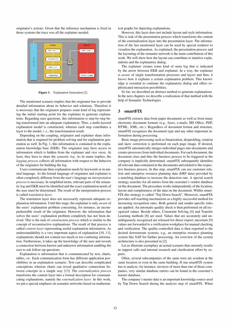
originator’s actions. Given that the inference mechanism is fixed inthose systems the trace was all the explainer needed.
Figure 1. Explanation Generation [2].
The mentioned scenario implies that the originator has to providedetailed information about its behavior and solutions. Therefore itis necessary that the originator prepares some kind of log represent-ing the initial starting point for the explainer to generate explana-tions. Regarding user questions, this information is step-by-step be-ing transformed into an adequate explanation. Thus, a multi-layeredexplanation model is constructed, whereas each step contributes alayer to the model, i. e., the transformation result.
Depending on the coupling, originator and explainer share infor-mation that is required for problem solving and for explanation gen-eration as well. In Fig. 1, this information is contained in the expla-nation knowledge base (EKB). The originator may have access toinformation which is hidden from the explainer and vice versa. Atleast, they have to share the semantic log. As its name implies, thelogging process collects all information with respect to the behaviorof the originator for building the log.
Users communicate their explanation needs by keywords or in nat-ural language. As the formal language of originator and explainer isoften completely different from the user’s language an interpretationprocess is necessary. In simplified terms, relevant parts of the seman-tic log and EKB must be identified and the exact explanation needs ofthe user must be determined. The result of the interpretation processis called translation layer.
The translation layer does not necessarily represent adequate ex-planation information. Until this stage, the explainer is only aware ofthe users’ explanation problem concerning, for instance, an incom-prehensible result of the originator. However, the information thatsolves the users’ explanation problem completely has not been de-rived. This is the task of construction process which is similar to theconcept of reconstructive explanations. The result of that process iscalled content layer representing useful explanation information. Asunderstandability is a very important aspect of explanation [10, 11],explanations should not contain too much or too confusing informa-tion. Furthermore, it takes up the knowledge of the user and revealsa connection between known and unknown information enabling theuser to ask follow-up questions.
Explanation is information that is communicated by text, charts,tables, etc. Each communication form has different application pos-sibilities in an explanation scenario. Text can describe complicatedconceptions whereas charts can reveal qualitative connections be-tween concepts in a simple way [13]. The externalization processtransforms the content layer into a formal description for communi-cating explanations, namely the externalization layer. In this work,we put a special emphasis on semantic networks based on mathemat-
ical graphs for depicting explanations.However, this layer does not include layout and style information.
This is task of the presentation process which transforms the contentof the externalization layer into the presentation layer. The informa-tion of the last mentioned layer can be used by special renderer tovisualize the explanation. As explained, the presentation process andthe layouting of the semantic network is the main contribution of thiswork. We will show how the layout can contribute to intuitive expla-nations and the explanatory dialog.
The explainer creates some kind of meta log that is indicatedby the arrow between EKB and explainer. In a way, the explaineris aware of single transformation processes and layers and thus, itknows how it explains a certain explanation problem. This knowl-edge is essential to continue the explanatory dialog and offers so-phisticated interaction possibilities.
So far, we described an abstract method to generate explanations.In the next chapters we describe a realization of that method with thehelp of Semantic Technologies.
3 smartFIX
smartFIX extracts data from paper documents as well as from manyelectronic document formats (e.g., faxes, e-mails, MS Office, PDF,HTML, XML, etc.). Regardless of document format and structure,smartFIX recognizes the document type and any other important in-formation during processing.
Basic image processing such as binarization, despeckling, rotationand skew correction is performed on each page image. If desired,smartFIX automatically merges individual pages into documents andcreates processes from individual documents. For each document, thedocument class and thus the business process to be triggered in thecompany is implicitly determined. smartFIX subsequently identifiesall relevant data contained in the documents and related to the respec-tive business process. In this step, smartFIX can use customer rela-tion and enterprise resource planning data (ERP data) provided bya matching database to increase the detection rate. A special searchstrategy searches for all entries from the customer’s vendor databaseon the document. The procedure works independently of the location,layout and completeness of the data on the document. Within smart-FIX this strategy is called “Top Down Search”. Moreover, smartFIXprovides self-teaching mechanisms as a highly successful method forincreasing recognition rates. Both general and sender-specific rulesare applied. An automatic quality check is then performed on all rec-ognized values. Beside others, Constraint Solving [4] and TransferLearning methods [8] are used. Values that are accurately and un-ambiguously recognized are released for direct export; uncertain [9]values are forwarded to a verification workplace for manual checkingand verification. The quality-controlled data is then exported to thedesired downstream systems, e.g., an enterprise resource planningsystem like SAP for further processing. An overview of the systemarchitecture is also presented in [2].
Let us illustrate exemplary an actual scenario that currently resultsin support calls and internal research and clarification effort by ex-perts.
Often, several subcompanies of the same trust are resident at thesame location or even in the same building. If one smartFIX systemhas to analyze, for instance, invoices of more than one of those com-panies, very similar database entries can be found in the customer’smaster database.
The company’s master data is an important knowledge source usedby Top Down Search during the analysis step of smartFIX. When
12
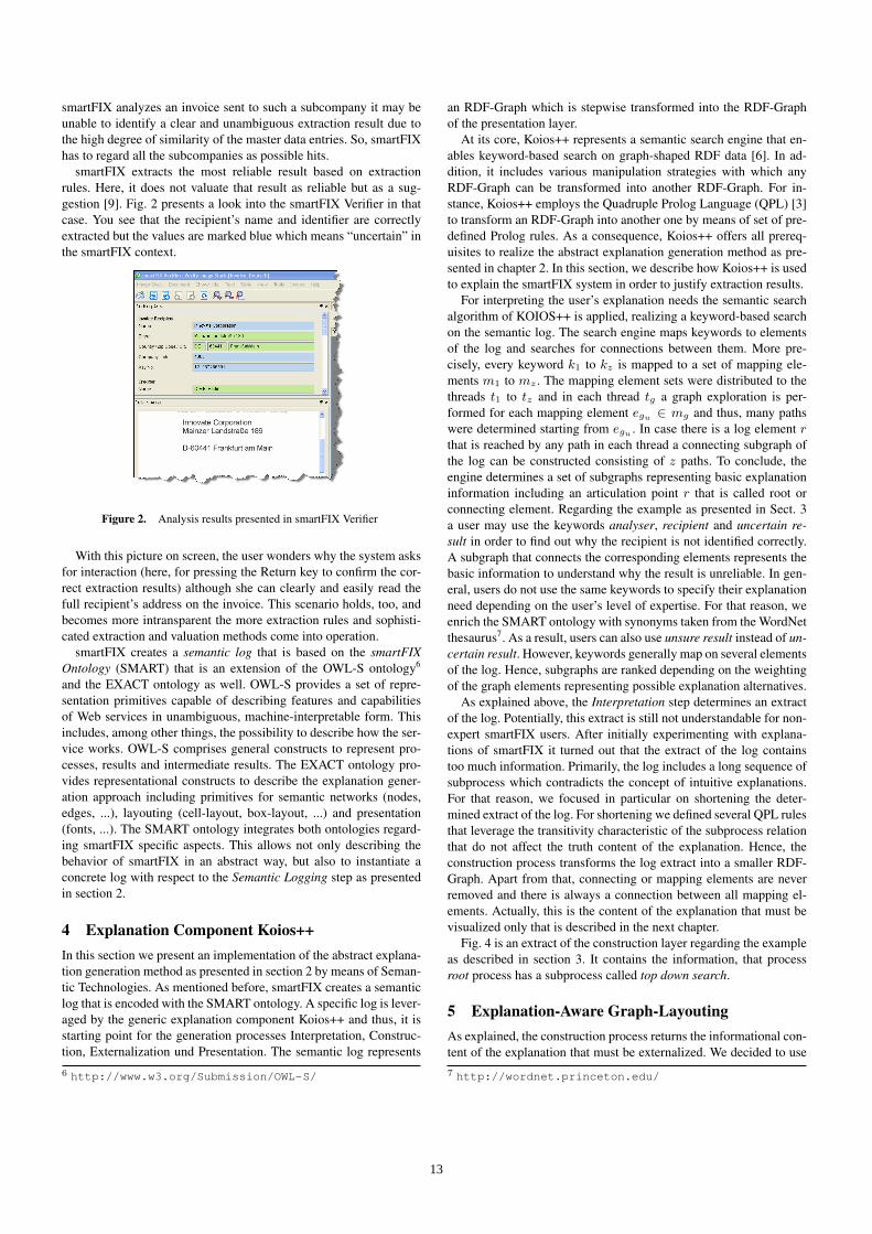
smartFIX analyzes an invoice sent to such a subcompany it may beunable to identify a clear and unambiguous extraction result due tothe high degree of similarity of the master data entries. So, smartFIXhas to regard all the subcompanies as possible hits.
smartFIX extracts the most reliable result based on extractionrules. Here, it does not valuate that result as reliable but as a sug-gestion [9]. Fig. 2 presents a look into the smartFIX Verifier in thatcase. You see that the recipient’s name and identifier are correctlyextracted but the values are marked blue which means “uncertain” inthe smartFIX context.
Figure 2. Analysis results presented in smartFIX Verifier
With this picture on screen, the user wonders why the system asksfor interaction (here, for pressing the Return key to confirm the cor-rect extraction results) although she can clearly and easily read thefull recipient’s address on the invoice. This scenario holds, too, andbecomes more intransparent the more extraction rules and sophisti-cated extraction and valuation methods come into operation.
smartFIX creates a semantic log that is based on the smartFIXOntology (SMART) that is an extension of the OWL-S ontology6
and the EXACT ontology as well. OWL-S provides a set of repre-sentation primitives capable of describing features and capabilitiesof Web services in unambiguous, machine-interpretable form. Thisincludes, among other things, the possibility to describe how the ser-vice works. OWL-S comprises general constructs to represent pro-cesses, results and intermediate results. The EXACT ontology pro-vides representational constructs to describe the explanation gener-ation approach including primitives for semantic networks (nodes,edges, ...), layouting (cell-layout, box-layout, ...) and presentation(fonts, ...). The SMART ontology integrates both ontologies regard-ing smartFIX specific aspects. This allows not only describing thebehavior of smartFIX in an abstract way, but also to instantiate aconcrete log with respect to the Semantic Logging step as presentedin section 2.
4 Explanation Component Koios++In this section we present an implementation of the abstract explana-tion generation method as presented in section 2 by means of Seman-tic Technologies. As mentioned before, smartFIX creates a semanticlog that is encoded with the SMART ontology. A specific log is lever-aged by the generic explanation component Koios++ and thus, it isstarting point for the generation processes Interpretation, Construc-tion, Externalization und Presentation. The semantic log represents
6 http://www.w3.org/Submission/OWL-S/
an RDF-Graph which is stepwise transformed into the RDF-Graphof the presentation layer.
At its core, Koios++ represents a semantic search engine that en-ables keyword-based search on graph-shaped RDF data [6]. In ad-dition, it includes various manipulation strategies with which anyRDF-Graph can be transformed into another RDF-Graph. For in-stance, Koios++ employs the Quadruple Prolog Language (QPL) [3]to transform an RDF-Graph into another one by means of set of pre-defined Prolog rules. As a consequence, Koios++ offers all prereq-uisites to realize the abstract explanation generation method as pre-sented in chapter 2. In this section, we describe how Koios++ is usedto explain the smartFIX system in order to justify extraction results.
For interpreting the user’s explanation needs the semantic searchalgorithm of KOIOS++ is applied, realizing a keyword-based searchon the semantic log. The search engine maps keywords to elementsof the log and searches for connections between them. More pre-cisely, every keyword k1 to kz is mapped to a set of mapping ele-ments m1 to mz . The mapping element sets were distributed to thethreads t1 to tz and in each thread tg a graph exploration is per-formed for each mapping element egu ∈ mg and thus, many pathswere determined starting from egu . In case there is a log element rthat is reached by any path in each thread a connecting subgraph ofthe log can be constructed consisting of z paths. To conclude, theengine determines a set of subgraphs representing basic explanationinformation including an articulation point r that is called root orconnecting element. Regarding the example as presented in Sect. 3a user may use the keywords analyser, recipient and uncertain re-sult in order to find out why the recipient is not identified correctly.A subgraph that connects the corresponding elements represents thebasic information to understand why the result is unreliable. In gen-eral, users do not use the same keywords to specify their explanationneed depending on the user’s level of expertise. For that reason, weenrich the SMART ontology with synonyms taken from the WordNetthesaurus7. As a result, users can also use unsure result instead of un-certain result. However, keywords generally map on several elementsof the log. Hence, subgraphs are ranked depending on the weightingof the graph elements representing possible explanation alternatives.
As explained above, the Interpretation step determines an extractof the log. Potentially, this extract is still not understandable for non-expert smartFIX users. After initially experimenting with explana-tions of smartFIX it turned out that the extract of the log containstoo much information. Primarily, the log includes a long sequence ofsubprocess which contradicts the concept of intuitive explanations.For that reason, we focused in particular on shortening the deter-mined extract of the log. For shortening we defined several QPL rulesthat leverage the transitivity characteristic of the subprocess relationthat do not affect the truth content of the explanation. Hence, theconstruction process transforms the log extract into a smaller RDF-Graph. Apart from that, connecting or mapping elements are neverremoved and there is always a connection between all mapping el-ements. Actually, this is the content of the explanation that must bevisualized only that is described in the next chapter.
Fig. 4 is an extract of the construction layer regarding the exampleas described in section 3. It contains the information, that processroot process has a subprocess called top down search.
5 Explanation-Aware Graph-LayoutingAs explained, the construction process returns the informational con-tent of the explanation that must be externalized. We decided to use7 http://wordnet.princeton.edu/
13
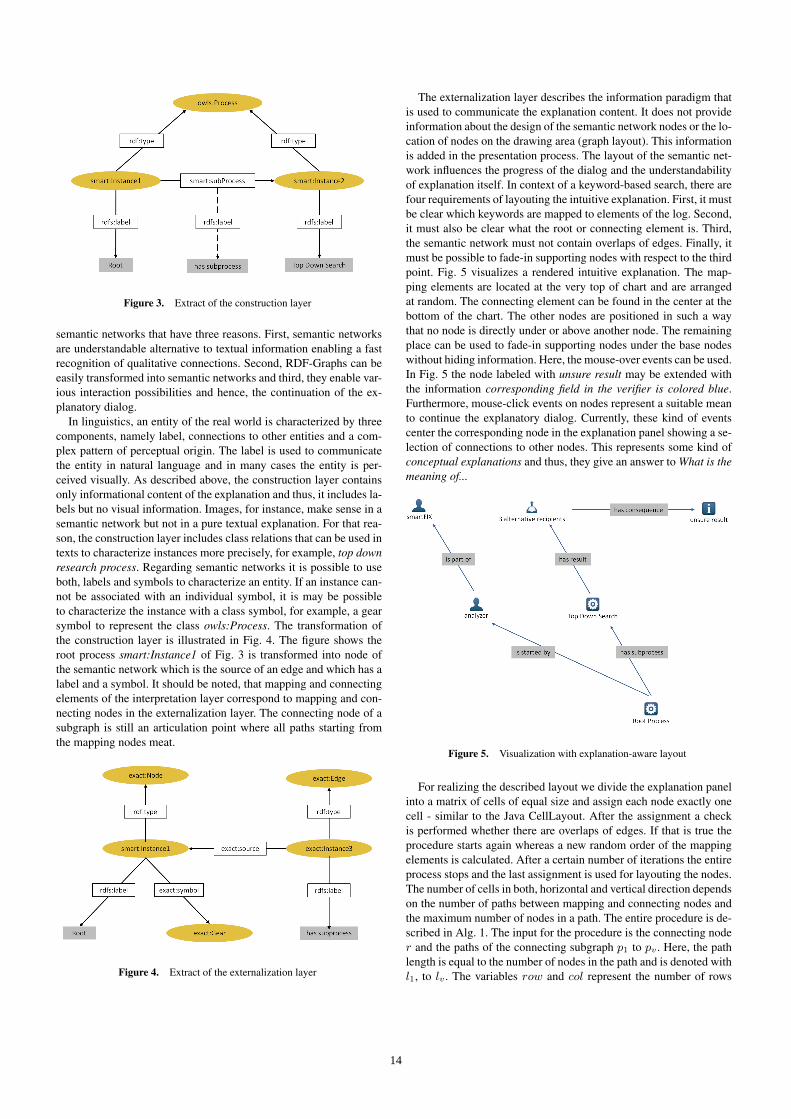
Figure 3. Extract of the construction layer
semantic networks that have three reasons. First, semantic networksare understandable alternative to textual information enabling a fastrecognition of qualitative connections. Second, RDF-Graphs can beeasily transformed into semantic networks and third, they enable var-ious interaction possibilities and hence, the continuation of the ex-planatory dialog.
In linguistics, an entity of the real world is characterized by threecomponents, namely label, connections to other entities and a com-plex pattern of perceptual origin. The label is used to communicatethe entity in natural language and in many cases the entity is per-ceived visually. As described above, the construction layer containsonly informational content of the explanation and thus, it includes la-bels but no visual information. Images, for instance, make sense in asemantic network but not in a pure textual explanation. For that rea-son, the construction layer includes class relations that can be used intexts to characterize instances more precisely, for example, top downresearch process. Regarding semantic networks it is possible to useboth, labels and symbols to characterize an entity. If an instance can-not be associated with an individual symbol, it is may be possibleto characterize the instance with a class symbol, for example, a gearsymbol to represent the class owls:Process. The transformation ofthe construction layer is illustrated in Fig. 4. The figure shows theroot process smart:Instance1 of Fig. 3 is transformed into node ofthe semantic network which is the source of an edge and which has alabel and a symbol. It should be noted, that mapping and connectingelements of the interpretation layer correspond to mapping and con-necting nodes in the externalization layer. The connecting node of asubgraph is still an articulation point where all paths starting fromthe mapping nodes meat.
Figure 4. Extract of the externalization layer
The externalization layer describes the information paradigm thatis used to communicate the explanation content. It does not provideinformation about the design of the semantic network nodes or the lo-cation of nodes on the drawing area (graph layout). This informationis added in the presentation process. The layout of the semantic net-work influences the progress of the dialog and the understandabilityof explanation itself. In context of a keyword-based search, there arefour requirements of layouting the intuitive explanation. First, it mustbe clear which keywords are mapped to elements of the log. Second,it must also be clear what the root or connecting element is. Third,the semantic network must not contain overlaps of edges. Finally, itmust be possible to fade-in supporting nodes with respect to the thirdpoint. Fig. 5 visualizes a rendered intuitive explanation. The map-ping elements are located at the very top of chart and are arrangedat random. The connecting element can be found in the center at thebottom of the chart. The other nodes are positioned in such a waythat no node is directly under or above another node. The remainingplace can be used to fade-in supporting nodes under the base nodeswithout hiding information. Here, the mouse-over events can be used.In Fig. 5 the node labeled with unsure result may be extended withthe information corresponding field in the verifier is colored blue.Furthermore, mouse-click events on nodes represent a suitable meanto continue the explanatory dialog. Currently, these kind of eventscenter the corresponding node in the explanation panel showing a se-lection of connections to other nodes. This represents some kind ofconceptual explanations and thus, they give an answer to What is themeaning of...
Figure 5. Visualization with explanation-aware layout
For realizing the described layout we divide the explanation panelinto a matrix of cells of equal size and assign each node exactly onecell - similar to the Java CellLayout. After the assignment a checkis performed whether there are overlaps of edges. If that is true theprocedure starts again whereas a new random order of the mappingelements is calculated. After a certain number of iterations the entireprocess stops and the last assignment is used for layouting the nodes.The number of cells in both, horizontal and vertical direction dependson the number of paths between mapping and connecting nodes andthe maximum number of nodes in a path. The entire procedure is de-scribed in Alg. 1. The input for the procedure is the connecting noder and the paths of the connecting subgraph p1 to pv . Here, the pathlength is equal to the number of nodes in the path and is denoted withl1, to lv . The variables row and col represent the number of rows
14
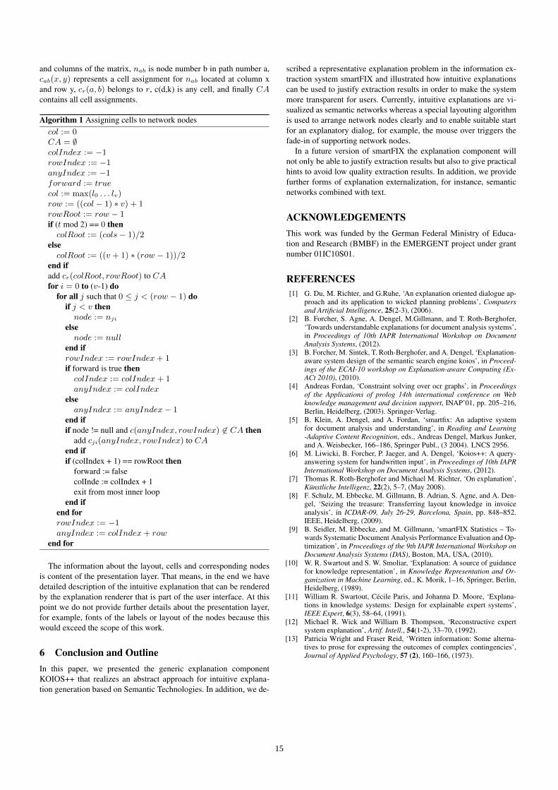
and columns of the matrix, nab is node number b in path number a,cab(x, y) represents a cell assignment for nab located at column xand row y, cr(a, b) belongs to r, c(d,k) is any cell, and finally CAcontains all cell assignments.
Algorithm 1 Assigning cells to network nodescol := 0CA = ∅colIndex := −1rowIndex := −1anyIndex := −1forward := truecol := max(l0 . . . lv)row := ((col − 1) ∗ v) + 1rowRoot := row − 1if (t mod 2) == 0 then
colRoot := (cols− 1)/2else
colRoot := ((v + 1) ∗ (row − 1))/2end ifadd cr(colRoot, rowRoot) to CAfor i = 0 to (v-1) do
for all j such that 0 ≤ j < (row − 1) doif j < v then
node := nji
elsenode := null
end ifrowIndex := rowIndex+ 1if forward is true then
colIndex := colIndex+ 1anyIndex := colIndex
elseanyIndex := anyIndex− 1
end ifif node != null and c(anyIndex, rowIndex) 6∈ CA then
add cji(anyIndex, rowIndex) to CAend ifif (colIndex + 1) == rowRoot then
forward := falsecolInde := colIndex + 1exit from most inner loop
end ifend forrowIndex := −1anyIndex := colIndex+ row
end for
The information about the layout, cells and corresponding nodesis content of the presentation layer. That means, in the end we havedetailed description of the intuitive explanation that can be renderedby the explanation renderer that is part of the user interface. At thispoint we do not provide further details about the presentation layer,for example, fonts of the labels or layout of the nodes because thiswould exceed the scope of this work.
6 Conclusion and OutlineIn this paper, we presented the generic explanation componentKOIOS++ that realizes an abstract approach for intuitive explana-tion generation based on Semantic Technologies. In addition, we de-
scribed a representative explanation problem in the information ex-traction system smartFIX and illustrated how intuitive explanationscan be used to justify extraction results in order to make the systemmore transparent for users. Currently, intuitive explanations are vi-sualized as semantic networks whereas a special layouting algorithmis used to arrange network nodes clearly and to enable suitable startfor an explanatory dialog, for example, the mouse over triggers thefade-in of supporting network nodes.
In a future version of smartFIX the explanation component willnot only be able to justify extraction results but also to give practicalhints to avoid low quality extraction results. In addition, we providefurther forms of explanation externalization, for instance, semanticnetworks combined with text.
ACKNOWLEDGEMENTSThis work was funded by the German Federal Ministry of Educa-tion and Research (BMBF) in the EMERGENT project under grantnumber 01IC10S01.
REFERENCES[1] G. Du, M. Richter, and G.Ruhe, ‘An explanation oriented dialogue ap-
proach and its application to wicked planning problems’, Computersand Artificial Intelligence, 25(2-3), (2006).
[2] B. Forcher, S. Agne, A. Dengel, M.Gillmann, and T. Roth-Berghofer,‘Towards understandable explanations for document analysis systems’,in Proceedings of 10th IAPR International Workshop on DocumentAnalysis Systems, (2012).
[3] B. Forcher, M. Sintek, T. Roth-Berghofer, and A. Dengel, ‘Explanation-aware system design of the semantic search engine koios’, in Proceed-ings of the ECAI-10 workshop on Explanation-aware Computing (Ex-ACt 2010), (2010).
[4] Andreas Fordan, ‘Constraint solving over ocr graphs’, in Proceedingsof the Applications of prolog 14th international conference on Webknowledge management and decision support, INAP’01, pp. 205–216,Berlin, Heidelberg, (2003). Springer-Verlag.
[5] B. Klein, A. Dengel, and A. Fordan, ‘smartfix: An adaptive systemfor document analysis and understanding’, in Reading and Learning-Adaptive Content Recognition, eds., Andreas Dengel, Markus Junker,and A. Weisbecker, 166–186, Springer Publ., (3 2004). LNCS 2956.
[6] M. Liwicki, B. Forcher, P. Jaeger, and A. Dengel, ‘Koios++: A query-answering system for handwritten input’, in Proceedings of 10th IAPRInternational Workshop on Document Analysis Systems, (2012).
[7] Thomas R. Roth-Berghofer and Michael M. Richter, ‘On explanation’,Kunstliche Intelligenz, 22(2), 5–7, (May 2008).
[8] F. Schulz, M. Ebbecke, M. Gillmann, B. Adrian, S. Agne, and A. Den-gel, ‘Seizing the treasure: Transferring layout knowledge in invoiceanalysis’, in ICDAR-09, July 26-29, Barcelona, Spain, pp. 848–852.IEEE, Heidelberg, (2009).
[9] B. Seidler, M. Ebbecke, and M. Gillmann, ‘smartFIX Statistics – To-wards Systematic Document Analysis Performance Evaluation and Op-timization’, in Proceedings of the 9th IAPR International Workshop onDocument Analysis Systems (DAS), Boston, MA, USA, (2010).
[10] W. R. Swartout and S. W. Smoliar, ‘Explanation: A source of guidancefor knowledge representation’, in Knowledge Representation and Or-ganization in Machine Learning, ed., K. Morik, 1–16, Springer, Berlin,Heidelberg, (1989).
[11] William R. Swartout, Cecile Paris, and Johanna D. Moore, ‘Explana-tions in knowledge systems: Design for explainable expert systems’,IEEE Expert, 6(3), 58–64, (1991).
[12] Michael R. Wick and William B. Thompson, ‘Reconstructive expertsystem explanation’, Artif. Intell., 54(1-2), 33–70, (1992).
[13] Patricia Wright and Fraser Reid, ‘Written information: Some alterna-tives to prose for expressing the outcomes of complex contingencies’,Journal of Applied Psychology, 57 (2), 160–166, (1973).
15
A Brief Review of Explanation in the Semantic WebRakebul Hasan1 and Fabien Gandon2
Abstract. Semantic Web applications use interconnected dis-tributed data and inferential capabilities to compute their results. Theusers of Semantic Web applications might find it difficult to under-stand how a result is produced or how a new piece of informationis derived in the process. Explanation enables users to understandthe process of obtaining results. Explanation adds transparency tothe process of obtaining results and enables user trust in the process.The concept of providing explanation was first introduced in expertsystems and later studied in different application areas. This paperprovides a brief review of existing research on explanation in the Se-mantic Web.
1 INTRODUCTION
Semantic Web applications use interconnected distributed data andinferential capabilities to compute their results. A user might notbe able to understand how a Semantic Web application has solveda given query deriving new information and integrating informationfrom data sources across the Web, and therefore the user might nottrust the result of such a query. Semantic Web applications shouldprovide explanations about how they obtain results in order to ensuretheir effectiveness and increase their user acceptance [21]. SemanticWeb applications should not only provide explanations about howthe answers were obtained, they should also explain and allow usersto follow the flows of information between them [20].
Expert systems were among the first software systems to includeexplanation facilities [13, 22, 28]. Explanation facilities in expertsystems have evolved from reasoning trace oriented explanations,primarily useful for developers and knowledge engineers, to moreuser oriented interactive explanations justifying why a system be-havior is correct, to casual explanations generated in a decoupledway from the line of reasoning. The realization of the explanationfacilities in expert systems were motivated by enabling transparencyin problem solving, imparting an understanding of why and how agiven conclusion was reached, and hence enabling trust on the rea-soning capabilities of expert systems. These developments motivatedadaptation and development of explanation facilities in other fieldssuch as machine learning [10, 27], case-based reasoning [8, 26], rec-ommender systems [29], and Semantic Web.
In this paper, we provide a brief review of the existing approachesto explanation in the Semantic Web. Our selection criterion for thereviewed works was Semantic Web applications and publicationswhich have contribution in explanation. We have used the keywordsearch feature in Google Scholar3 and also its Cited by feature for therelevant publications for discovering more publications. In addition,
1 INRIA Sophia Antipolis –Wimmics, France, email: [email protected] INRIA Sophia Antipolis – Wimmics, France, email: [email protected] http://scholar.google.com/
we have examined all the previous publications of the Explanation-aware Computing workshop series. We have also examined the pre-vious publications of the International Semantic Web Conference se-ries. We selected a given work if it is in the domain of the SemanticWeb and it has contribution in the field of explanation. Our objec-tive was to extract and analyze the important aspects of explanation-aware Semantic Web systems from these reviewed research, and fi-nally to provide our perspective on these aspects. A detailed versionof this paper can be found in the research report in [11].
The paper is organized as follows. In Section 2, we present the re-quirements and the design principles of explanation-aware SemanticWeb applications. In Section 3, we provide an overview of differ-ent approaches to represent the metadata which enable support forreasoning and provenance information. In Section 4, we provide anoverview of different approaches for generation and presentation ofexplanations. In Section 5, we focus our discussion on the importantaspects of explanation approaches in the Semantic Web. In Section 6,we conclude the paper.
2 DESIGNING EXPLANATION-AWARESEMANTIC WEB APPLICATIONS
McGuinnesset al. [20] discuss the requirements for Semantic Webapplications form an explanation perspective. The paradigm shift in-troduced by the Semantic Web applications, from answering queriesby retrieving explicitly stored information to using inferential capa-bilities, generates new requirements to ensure their effective use:“ap-plications must provide explanation capabilities showing how resultswere obtained”. McGuinnesset al. characterize collaboration, auton-omy, and the use of ontologies as the important features of SemanticWeb applications from an explanation perspective. Given these fea-tures, different types of explanations, machine and human consump-tion of explanations, and trust are the important criteria of SemanticWeb applications.
In [21], McGuinnesset al. present requirements for distributedand portable justifications, and subsequently present justifications asuser-friendly explanations. An explanation infrastructure should sup-port knowledge provenance to allow users to understand the sourceinformation used in reasoning processes and hence enable user truston background reasoners. Support for reasoning information shouldbe also provided to enable users to understand what steps havebeen performed by reasoners. An explanation infrastructure shouldsupport generating human understandable explanation. Explanationsshould be presented with different degrees of detail taking into ac-count the users’ expertise and problem context.
Forcher et al. present the explanation-aware system design(EASD) principles in [9]. The EASD principles concern two keyaspects, namely the development and the runtime of a system. Theintegration of explanation capabilities in a system during its devel-
16
opment should not be too complicated and should not effect systemperformance and efficiency. Concerning the runtime aspect, the sys-tem must be aware of the explanation scenario and must be able pro-vide explanation accordingly during its runtime. Forcheret al. com-plement the EASD principles with an abstract architecture of a multi-layered explanation model considering the main participants in anyexplanation scenario.
3 METADTA FOR EXPLANATION
Different approaches use different kinds of metadata for generat-ing explanations in the context of Semantic Web. McGuinnessetal. [19] describe explanation as “Semantic Web metadata about howresults were obtained”. Provenance metadata concerning informationsources such as how, when, and from whom any given piece of datais obtained is an important aspect of explanation metadata. Explana-tions with detailed provenance information provide additional con-text and enable users to verify a given source of information. Meta-data representing information manipulation steps and their depen-dencies are commonly known as justifications. Justifications facili-tate rich explanation of how a conclusion was drawn. Trust relatedmetadata is another useful aspect which enables providing explana-tion with integrated trust information.
In [25], McGuinnesset al. present an explanation interlinguacalled Proof Markup Language (PML)4 to represent explanationmetadata. PML consists of three OWL ontologies. The PML prove-nance ontology (PML-P) provides primitives for representing realworld things (e.g. information, documents, people) and their proper-ties (e.g. name, creation date-time, description, owners and authors).The PML justification ontology (PML-J) provides primitives for en-coding justifications for derivations of conclusions. A justificationcan be a logical reasoning step, or any kind of computation process,or a factual assertion or assumption. The PML trust ontology (PML-T) provides primitives for representing trust assertions concerningsources and belief assertions concerning information.
The authors in [24] introduce a restricted subset of PML constructsand tools for encoding very basic justifications and performing taskssuch as retrieval and browsing of provenance information. The au-thors present strategies for lightweight use of PML and for simplify-ing encoding using PML. PML-Lite5 is another variant of PML. It isenvisioned to construct a simple subset of three PML modules. PML-Lite takes an event based modeling approach. It provides primitivesto represent provenance of data flows and data manipulations.
The AIR (AccountabilityIn RDF) [16] rule language uses the AIRJustification Ontology (AIRJ) to represent justifications produced bythe AIR reasoner. AIRJ extends the PML-Lite event-based approach.The reasoning steps of AIR reasoner are interpreted as events. AIRJprovides primitives to represent the different events and the opera-tions performed by the AIR reasoner.
4 GENERATION AND PRESENTATION OFEXPLANATION
As discussed in explanation requirements, what types of explana-tions are generated and how they are presented to users are importantcriteria for success of explanation-aware systems.
OntoNova [2] is an ontology-based question answering system inchemistry domain. OntoNova provides explanations in natural lan-guage with its answers. It generates answer justifications in a meta-
4 http://tw.rpi.edu/portal/ProofMarkup Language5 http://tw.rpi.edu/web/project/TAMI/PML-Lite
inferencing step.The OntoNova inference engine produces log fileswhich represent proof trees for answers. These files are given as aninput to a second meta-inference step. This second meta-inferencestep explains the proof trees in natural language with the descriptionof how answers were derived. OntoNova allows specifying meta-inference rules for the original rules for question answering. Thetwo step method for providing explanation has advantages such as:(i) provision of additional information with explanations when prooftrees do not contain enough information, (ii) filter explanation pathsin case of redundancies for same results, (iii) provision of explana-tion with different degrees of detail, (iv) provision of personalizedexplanation for different contexts.
Inference Web [19, 20, 21] is an explanation infrastructure whichaddresses explanation requirements of web services discovery, pol-icy engines, first order logic theorem provers, task execution, and textanalytics. Information manipulation traces of these various kinds ofsystems are encoded as PML proofs. Inference Web provides a setof software tools and services for building, presenting, maintaining,and manipulating PML proofs. The IWBase component of InferenceWeb provides an interconnected network of distribute repositories ofexplanation related meta information. IWBase provides a registry-based solution for publishing and accessing information. Contentpublishers can register metadata and other supporting informationsuch as inference rules, and inference engines. IWBase provides ser-vices to populate PML proofs. IWBase exposes the populated meta-data as PML documents and provides browsing interfaces to ac-cess them. These PML documents can be also accessed by resolvingtheir URI references. The IWSearch component of Inference Websearches for PML documents on the Web and maintains an inventoryof these documents. Users can then search for PML documents us-ing different search interfaces offered by IWSearch. Inference Webprovides a browser called IWBrowser which can display PML proofsand explanations in number of different formats and styles. The richpresentations include a directed acyclic graph (DAG) view knownas global view, a focused view enabling step-by-step navigation be-tween related explanations, a filtered view to show selected parts ofan explanation, an abstraction view which shows abstract views ofexplanations with different degrees of detail, and finally a discourseview which allows follow-up questions. The IWAbstractor compo-nent of Inference Web allows users to write abstraction patterns forPML proofs. It matches these patterns against PML proofs to providean abstract view. Inference Web includes a general trust infrastruc-ture called IWTrust which provides explanations with trust relatedinformation and allows filtering out unreliable information. IWTrustincludes representation of trust aspects and trust computation ser-vices. In addition, it provides a browser with trust view to renderthe trust annotation. In the trust view, different fragments of a pageare rendered in different colors depending on the trustworthiness ofthem. This allows users to have an understanding of the trustworthi-ness of rendered information just by looking at a rendered page.
TheWIQA - Web Information Quality Assessment Framework [6]provides functionalities for quality-based information filtering. TheWIQA framework allows to employ different policies for informa-tion filtering. These policies combine content-based, context-based,and rating-based quality assessment metrics. An information con-sumer’s understanding of the employed quality assessment metrics isa major factor that influence whether the information consumer trustor distrust any quality assessment result. The WIQA framework pro-vides detailed explanation of information filtering process for sup-porting information consumers in their trust decisions. It is able toprovide explanation of why a given piece of information satisfies a
17
given WIQA-PL policy. It provides explanations in natural languagefor human consumption andexplanations in RDF for further pro-cessing by software applications. The explanation generation processcontains two steps. First, WIQA generates the parts of explanationsof why constraints expressed as graph patterns are satisfied. Thesedifferent parts of explanations are generated using a template mech-anism. In the second step, these explanation parts are supplementedwith additional explanations of why constraints expressed as exten-sion functions are satisfied. In the RDF-based explanations, WIQAdescribes the explanation trees (parts and subparts of an explanation)using the Explanation (EXPL) Vocabulary6.
The authors in [3, 4] present a nonmonotonic rule system based ondefeasible logic which is able to answer queries and provide proof ex-planations. Defeasible logic enables reasoning with incomplete andinconsistent information. The traces of the underlying logic engineare transformed to defeasible logic proofs. The authors introducean extension to RuleML7, a unifying family of Web rule languages,to enable formal representation of explanations of defeasible logicreasoning. Software agents can consume and verify these proofs de-scribed using the RuleML extension. In addition, the authors presentgraphical user interfaces to visualize the proofs and interact withthem. Finally, the authors present an agent interface to enable multi-agent systems to interact with their system.
Horridgeet al. present two fine-grained subclasses of justificationscalled laconic justifications and precise justifications [15]. Laconicjustifications consists of axioms that contain no superfluous part. Pre-cise justifications are derived from laconic justifications. Each ax-ioms of a precise justification represents a minimal part of the justifi-cation. The authors also present an optimized algorithm to computelaconic justifications showing the feasibility of computing laconicjustifications and precise justifications in practice. The authors pro-vide a Protege ontology editor8 plugin as a tool to compute thesetypes of justifications9. This tool shows justification-based explana-tions of entailments. A user can select an entailment from a list ofprovided entailments and the tool shows the justification-based ex-planation for the selected entailment.
Kotowski and Bry [18] argue that explanation complements theincremental development of knowledge bases in frequently chang-ing wiki environments. The authors present a semantic wiki calledKiWi 10 which takes a rule-based inconsistency tolerant reasoning ap-proach that has the capability of explaining how a given piece of in-formation was derived. The reasoning approach also allows knowl-edge base updates in an efficient way by using reason maintenance.The authors argue that providing explanation is important for sup-porting users’ trust and facilitates determining main causes of incon-sistencies. KiWi stores the justifications of all the derivations anduses them for providing explanations and also for reason mainte-nance. KiWi presents explanations as natural language explanationsand as tree-based explanations highlighting the derivation paths.
Forcheret al. [9] describe the realization of the EASD approach ina semantic search engine called KOIOS. The KOIOS semantic searchengine allows keyword-based search on RDF data. The KOIOSsearch engine first computes a set of relevant SPARQL queries froma set of given keywords. Users then select the appropriate queriesto query a triple store containing RDF data. The search results areprovided with explanations about how they are computed. The ex-
6 http://www4.wiwiss.fu-berlin.de/bizer/triqlp/7 http://ruleml.org8 http://protege.stanford.edu/9 http://owl.cs.manchester.ac.uk/explanation/10 http://www.kiwi-project.eu/
planations justify how keywords are mapped to concepts and howconcepts are connected. In addition, the explanations interpret theperformed queries in an understandable way. The authors introducea set of ontologies to formally describe the content of explanationsprovided by KOIOS. The KOIOS Process Language (KPL) is usedto describe the behavior of the problem solving process. The Math-ematical Graph Language (MGL) is used to realize the graph basedview of the process model. Finally, another ontology called VGL isused for visualizing graph based information. In addition, KOIOSincludes a set of rules to transform a certain model described inRDF. The trace model is described in RDF and transformed step-by-step to a presentation model using a set of rules to provide differentviews of explanations. KOIOS provides graphical explanations forkeyword-based search with graphical representation of correspond-ing SPARQL queries and the results of the query. Users can also get atextual explanation of any concept from the graphical representationby clicking on any concept. KOIOS also provides justification-basedgraphical explanation of search keyword to concept type mapping.
The AIR rule language [16] supports generation of machine con-sumable explanations. The AIR reasoner annotates all of its per-formed actions and the dependencies between these actions. Theseannotations are recursively converted to AIR justifications. To gen-erate natural language explanation, rule authors can specify a naturallanguage description in the definition of a rule itself which can con-tain variables. These variable values are replaced with the currentvalue during the reasoning process. AIR also provide a feature todeclaratively modify justifications. This allows the degrees of detailin AIR justifications to be selectively controlled. The authors of AIRsuggest registering AIR with the Inference Web infrastructure anduse their toolkit to provide explanations for human consumption.
5 DISCUSSION AND PERSPECTIVE
The research we have reviewed exposes several dimensions of expla-nation in the context of the Semantic Web:
Infrastructure: With the increasing growth of sharing SemanticWeb data as part of the Linked Data [5] initiatives, it is importantthat data publishers can publish their data with explanation relatedmetadata with ease. Explanation infrastructures should be able to ac-commodate common data publishing principles. Semantic Web ex-planation infrastructures should also address heterogeneous and dis-tributed nature of the Web. Inference Web intent to address these is-sues. For example, explanation metadata can be described in PMLdocuments and resolved using the URIs of the documents. How-ever, Inference Web provides a centralized solution for publishingand consuming explanation metadata. Explanation metadata shouldbe registered in the Inference Web repository to use their facili-ties. Moreover, the published metadata using Inference Web facili-ties have compatibility issues with the Linked Data principles. Forinstance, not all the resources in PML documents are identifiableby URIs as there are blank nodes in PML documents. Our ongoingwork [12] on applying the Linked Data principles intent to addressthese issues. With regard to diversity of different representation, ex-planation metadata should be published promoting interoperability.The W3C PROV-DM data model [23] can be used as an interchangedata model across different systems in this regard. Different systemscan define their explanation metadata model as application-specificand domain-specific extensions of PROV-DM. Applications acrossthe Web can then make sense of explanation metadata in a unifiedmanner. Consumers of these explanation metadata can use explana-tion presentation and visualization tools according to their needs.
18
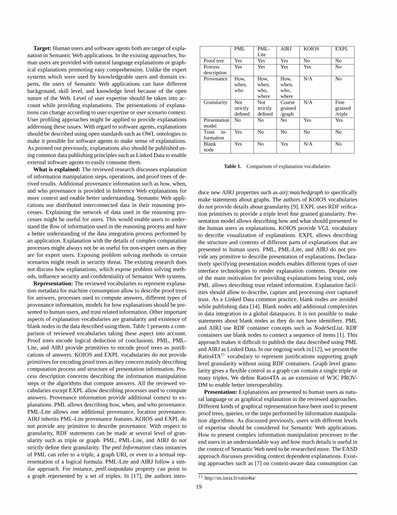
Target: Human users and software agents both are target of expla-nation in Semantic Web applications. In the existing approaches, hu-man users are provided with natural language explanations or graph-ical explanations promoting easy comprehension. Unlike the expertsystems which were used by knowledgeable users and domain ex-perts, the users of Semantic Web applications can have differentbackground, skill level, and knowledge level because of the opennature of the Web. Level of user expertise should be taken into ac-count while providing explanations. The presentations of explana-tions can change according to user expertise or user scenario context.User profiling approaches might be applied to provide explanationsaddressing these issues. With regard to software agents, explanationsshould be described using open standards such as OWL ontologies tomake it possible for software agents to make sense of explanations.As pointed out previously, explanations also should be published us-ing common data publishing principles such as Linked Data to enableexternal software agents to easily consume them.
What is explained: The reviewed research discusses explanationof information manipulation steps, operations, and proof trees of de-rived results. Additional provenance information such as how, when,and who provenance is provided in Inference Web explanations formore context and enable better understanding. Semantic Web appli-cations use distributed interconnected data in their reasoning pro-cesses. Explaining the network of data used in the reasoning pro-cesses might be useful for users. This would enable users to under-stand the flow of information used in the reasoning process and havea better understanding of the data integration process performed byan application. Explanation with the details of complex computationprocesses might always not be as useful for non-expert users as theyare for expert users. Exposing problem solving methods in certainscenarios might result in security threat. The existing research doesnot discuss how explanations, which expose problem solving meth-ods, influence security and confidentiality of Semantic Web systems.
Representation: The reviewed vocabularies to represent explana-tion metadata for machine consumption allow to describe proof treesfor answers, processes used to compute answers, different types ofprovenance information, models for how explanations should be pre-sented to human users, and trust related information. Other importantaspects of explanation vocabularies are granularity and existence ofblank nodes in the data described using them. Table 1 presents a com-parison of reviewed vocabularies taking these aspect into account.Proof trees encode logical deduction of conclusions. PML, PML-Lite, and AIRJ provide primitives to encode proof trees as justifi-cations of answers. KOIOS and EXPL vocabularies do not provideprimitives for encoding proof trees as they concern mainly describingcomputation process and structure of presentation information. Pro-cess description concerns describing the information manipulationsteps or the algorithms that compute answers. All the reviewed vo-cabularies except EXPL allow describing processes used to computeanswers. Provenance information provide additional context to ex-planations. PML allows describing how, when, and who provenance.PML-Lite allows one additional provenance, location provenance.AIRJ inherits PML-Lite provenance features. KOIOS and EXPL donot provide any primitive to describe provenance. With respect togranularity, RDF statements can be made at several level of gran-ularity such as triple or graph. PML, PML-Lite, and AIRJ do notstrictly define their granularity. Thepml:Information class instancesof PML can refer to a triple, a graph URI, or even to a textual rep-resentation of a logical formula. PML-Lite and AIRJ follow a sim-ilar approach. For instance,pmll:outputdata property can point toa graph represented by a set of triples. In [17], the authors intro-
PML PML-Lite
AIRJ KOIOS EXPL
Proof tree Yes Yes Yes No NoProcessdescription
Yes Yes Yes Yes No
Provenance How,when,who
How,when,who,where
How,when,who,where
N/A No
Granularity Notstrictlydefined
Notstrictlydefined
Coarsegrained/graph
N/A Finegrained/triple
Presentationmodel
No No No Yes Yes
Trust in-formation
Yes No No No No
Blanknode
Yes No Yes N/A No
Table 1. Comparison of explanation vocabularies
duce new AIRJ properties such asairj:matchedgraph to specificallymake statements about graphs. The authors of KOIOS vocabulariesdo not provide details about granularity [9]. EXPL uses RDF reifica-tion primitives to provide a triple level fine grained granularity. Pre-sentation model allows describing how and what should presented tothe human users as explanations. KOIOS provide VGL vocabularyto describe visualization of explanations. EXPL allows describingthe structure and contents of different parts of explanations that arepresented to human users. PML, PML-Lite, and AIRJ do not pro-vide any primitive to describe presentation of explanations. Declara-tively specifying presentation models enables different types of userinterface technologies to render explanation contents. Despite oneof the main motivation for providing explanations being trust, onlyPML allows describing trust related information. Explanation facil-ities should allow to describe, capture and processing over capturedtrust. As a Linked Data common practice, blank nodes are avoidedwhile publishing data [14]. Blank nodes add additional complexitiesin data integration in a global dataspaces. It is not possible to makestatements about blank nodes as they do not have identifiers. PMLand AIRJ use RDF container concepts such asNodeSetList. RDFcontainers use blank nodes to connect a sequence of items [1]. Thisapproach makes it difficult to publish the data described using PMLand AIRJ as Linked Data. In our ongoing work in [12], we present theRatio4TA11 vocabulary to represent justifications supporting graphlevel granularity without using RDF containers. Graph level granu-larity gives a flexible control as a graph can contain a single triple ormany triples. We define Ratio4TA as an extension of W3C PROV-DM to enable better interoperability.
Presentation: Explanations are presented to human users as natu-ral language or as graphical explanation in the reviewed approaches.Different kinds of graphical representation have been used to presentproof trees, queries, or the steps performed by information manipula-tion algorithms. As discussed previously, users with different levelsof expertise should be considered for Semantic Web applications.How to present complex information manipulation processes to theend users in an understandable way and how much details is useful inthe context of Semantic Web need to be researched more. The EASDapproach discusses providing context dependent explanations. Exist-ing approaches such as [7] on context-aware data consumption can
11 http://ns.inria.fr/ratio4ta/
19
be also applied to address providing different types of explanationsdepending on differenttypes of users. Presentation models can bedeclaratively defined and associated with different context related in-formation. Different user interface rendering methodologies can thenbe applied on the defined presentation models to provide the final ex-planation user interfaces.
Interaction: Explanations should be provided with navigationsupport to enable end users to discover more related information.Other interaction models such as follow up or feedback mechanismsmight also be useful in certain contexts. Inference Web provides ex-planation with navigation and follow up support. How users can in-teract trust information based on the provided explanations would beanother interesting area to explore.
Trust: The reviewed research lacks studies about understandinghow explanations influence user trust in the context of Semantic Web.In contrast to the expert systems, Semantic Web applications havenew dimensions such as openness and distributed. Furthermore, Se-mantic Web applications have much broader and diverse user basethan expert systems. How these aspects of Semantic Web influencetrust needs to be studied more. In the existing work, only InferenceWeb provides an infrastructure for trust which includes a vocabularyto describe trust related information. However, how users trust can becaptured and processed for further trust assertions is not discussed.Another interesting area to explore would be how explanation ap-proaches can be applied to explain trust itself. For instance, expla-nation can be provided about who have trusted a given resource orabout trust rating calculations.
6 CONCLUSION
In this paper, we have presented an overview of the design principlesof explanation-aware Semantic Web systems, representation and us-age of explanation related metadata, and finally how explanationsare generated and presented to end users. We have also presented adiscussion on the important aspects of ongoing research relating toexplanation in the context of Semantic Web.
ACKNOWLEDGEMENTS
The work presented in this paper is supported by the CONTINT pro-gramme of French National Agency for Research (ANR) under theKolflow project (ANR-2010-CORD-021-02).
REFERENCES
[1] P. Hayes and B. McBride, eds., ‘RDF semantics’,W3C recommenda-tion, (2004).
[2] J. Angele, E. Moench, H. Oppermann, S. Staab, and D. Wenke,‘Ontology-based query and answering in chemistry: Ontonova projecthalo’, in The Semantic Web - ISWC 2003, eds., D. Fensel, K. Sycara,and J. Mylopoulos, volume 2870 ofLecture Notes in Computer Science,913–928, Springer Berlin / Heidelberg, (2003).
[3] G. Antoniou, A. Bikakis, N. Dimaresis, M. Genetzakis, G. Georgalis,G. Governatori, E. Karouzaki, N. Kazepis, D. Kosmadakis, M. Kritso-takis, G. Lilis, A. Papadogiannakis, P. Pediaditis, C. Terzakis, R. Theo-dosaki, and D. Zeginis, ‘Proof explanation for the semantic web us-ing defeasible logic’, inKnowledge Science, Engineering and Manage-ment, eds., Z. Zhang and J. Siekmann, volume 4798 ofLecture Notesin Computer Science, 186–197, Springer Berlin / Heidelberg, (2007).
[4] N. Bassiliades, G. Antoniou, and G. Governatori, ‘Proof explanationin the DR-DEVICE system’, inProc. of 1st Int’l Conference on WebReasoning and Rule Systems, pp. 249–258. Springer, (2007).
[5] T. Berners-Lee. Linked data. W3C Design Issueshttp://www.w3.org/DesignIssues/LinkedData.html, 2006.
[6] C. Bizer, Quality-Driven Information Filtering in the Context of Web-Based Information Systems, Ph.D. dissertation, Freie Universitat Berlin,Universitatsbibliothek, 2007.
[7] L. Costabello, ‘DC proposal: PRISSMA, towards mobile adaptive pre-sentation of the web of data’, inThe Semantic Web ISWC 2011, eds.,L. Aroyo, C. Welty, H. Alani, J. Taylor, A. Bernstein, L. Kagal, N. Noy,and E. Blomqvist, volume 7032 ofLecture Notes in Computer Science,269–276, Springer Berlin / Heidelberg, (2011).
[8] D. Doyle, A. Tsymbal, and P. Cunningham, ‘A review of explanationand explanation in case-based reasoning’, Technical Report TCD-CS-2003-41, Trinity College Dublin, (2003).
[9] B. Forcher, M. Sintek, T. Roth-Berghofer, and A. Dengel, ‘Explanation-aware system design of the semantic search engine koios’, inProc. ofthe the 5th Int’l. Workshop on Explanation-aware Computing, (2010).
[10] A. Glass,Explanation of Adaptive Systems, Ph.D. dissertation, StanfordUniversity, 2011.
[11] R. Hasan and F. Gandon, ‘Explanation in the Semantic Web: a surveyof the state of the art’, Research Report RR-7974, INRIA, (2012).
[12] R. Hasan and F. Gandon, ‘Linking justifications in the collaborativesemantic web applications’, inProc. of the 21st Int’l Conference Com-panion on World Wide Web, WWW ’12 Companion, pp. 1083–1090.ACM, (2012).
[13] S.R. Haynes,Explanation in Information Systems: A Design RationaleApproach, Ph.D. dissertation, The London School of Economics, 2001.
[14] T. Heath and C. Bizer,Linked Data: Evolving the Web into a GlobalData Space, Morgan & Claypool, 1st edn., 2011.
[15] M. Horridge, B. Parsia, and U. Sattler, ‘Laconic and precise justifica-tions in OWL’, in Proc. of the 7th Int’l Conference on the SemanticWeb, ISWC ’08, pp. 323–338. Springer-Verlag, (2008).
[16] L. Kagal, I. Jacobi, and A. Khandelwal, ‘Gasping for AIR – why weneed linked rules and justifications on the semantic web’, TechnicalReport MIT-CSAIL-TR-2011-023, MIT, (2011).
[17] A. Khandelwal, L. Ding, I. Jacobi, L. Kagal, and D.L. McGuin-ness. PML based AIR justification.http://tw.rpi.edu/proj/tami/PML_Based_AIR_Justification, 2011.
[18] J. Kotowski and F. Bry, ‘A perfect match for reasoning, explanationand reason maintenance: OWL 2 RL and semantic wikis’, inProc. of5th Semantic Wiki Workshop, (2010).
[19] D.L. McGuinness, Li Ding, A. Glass, C. Chang, H. Zeng, and V. Fur-tado, ‘Explanation interfaces for the semantic web: Issues and mod-els’, in Proc. of the 3rd Int’l Semantic Web User Interaction Workshop,(2006).
[20] D.L. McGuinness, V. Furtado, P. Pinheiro da Silva, L. Ding, A. Glass,and C. Chang, ‘Explaining semantic web applications.’, inSemanticWeb Engineering in the Knowledge Society, (2008).
[21] D.L. McGuinness and P Pinheiro da Silva, ‘Explaining answers fromthe semantic web: the inference web approach’,Web Semantics: Sci-ence, Services and Agents on the World Wide Web, 1(4), 397 – 413,(2004).
[22] J.D. Moore and W.R. Swartout, ‘Explanation in expert systemss: A sur-vey’, Research Report ISI/RR-88-228, University of Southern Califor-nia, (1988).
[23] L. Moreau and P. Missier, ‘PROV-DM: The PROV data model’,WorldWide Web Consortium, Fourth Public Working Draft, (2012).
[24] P. Pinheiro da Silva, D.L. McGuinness, N. Del Rio, and L. Ding, ‘In-ference web in action: Lightweight use of the proof markup language’,in Proc. of the 7th Int’l Semantic Web Conference, ISWC ’08, pp. 847–860, (2008).
[25] P. Pinheiro da Silva, D.L. McGuinness, and R. Fikes, ‘A proof markuplanguage for semantic web services’,Information Systems, 31(4-5),381–395, (2006).
[26] T. Roth-Berghofer, ‘Explanations and case-based reasoning: Founda-tional issues’, inAdvances in Case-Based Reasoning, eds., P. Funk andP.A.G. Calero, pp. 389–403. Springer-Verlag, (2004).
[27] S. Stumpf, V. Rajaram, L. Li, M. Burnett, T. Dietterich, E. Sullivan,R. Drummond, and J. Herlocker, ‘Toward harnessing user feedback formachine learning’, inProc. of the 12th international conference on In-telligent user interfaces, IUI ’07, pp. 82–91. ACM, (2007).
[28] W. Swartout, C. Paris, and J. Moore, ‘Explanations in knowledge sys-tems: design for explainable expert systems’,IEEE Expert, 6(3), 58–64, (1991).
[29] N. Tintarev and J. Masthoff, ‘A survey of explanations in recommendersystems’,ICDE07 Workshop on Recommender Systems and IntelligentUser Interfaces, (2007).
20
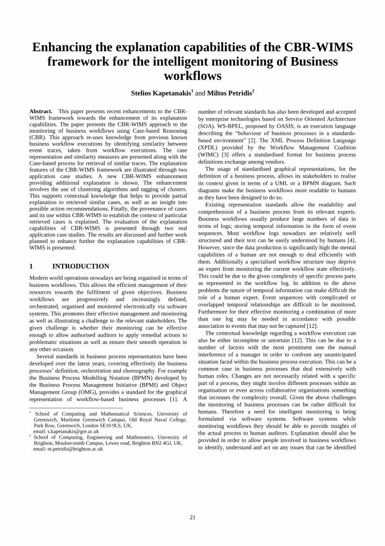
Enhancing the explanation capabilities of the CBR-WIMS framework for the intelligent monitoring of Business
workflows
Stelios Kapetanakis1 and Miltos Petridis
2
Abstract.1 This paper presents recent enhancements to the CBR-WIMS framework towards the enhancement of its explanation capabilities. The paper presents the CBR-WIMS approach to the monitoring of business workflows using Case-based Reasoning (CBR). This approach re-uses knowledge from previous known business workflow executions by identifying similarity between event traces, taken from workflow executions. The case representation and similarity measures are presented along with the Case-based process for retrieval of similar traces. The explanation features of the CBR-WIMS framework are illustrated through two application case studies. A new CBR-WIMS enhancement providing additional explanation is shown. The enhancement involves the use of clustering algorithms and tagging of clusters. This supports contextual knowledge that helps to provide partial explanation to retrieved similar cases, as well as an insight into possible action recommendations. Finally, the provenance of cases and its use within CBR-WIMS to establish the context of particular retrieved cases is explained. The evaluation of the explanation capabilities of CBR-WIMS is presented through two real application case studies. The results are discussed and further work planned to enhance further the explanation capabilities of CBR-WIMS is presented.
1 INTRODUCTION
Modern world operations nowadays are being organised in terms of
business workflows. This allows the efficient management of their
resources towards the fulfilment of given objectives. Business
workflows are progressively and increasingly defined,
orchestrated, organised and monitored electronically via software
systems. This promotes their effective management and monitoring
as well as illustrating a challenge to the relevant stakeholders. The
given challenge is whether their monitoring can be effective
enough to allow authorised auditors to apply remedial actions to
problematic situations as well as ensure their smooth operation in
any other occasion.
Several standards in business process representation have been
developed over the latest years, covering effectively the business
processes’ definition, orchestration and choreography. For example
the Business Process Modelling Notation (BPMN) developed by
the Business Process Management Initiative (BPMI) and Object
Management Group (OMG), provides a standard for the graphical
representation of workflow-based business processes [1]. A
1 School of Computing and Mathematical Sciences, University of
Greenwich, Maritime Greenwich Campus, Old Royal Naval College, Park Row, Greenwich, London SE10 9LS, UK,
email: [email protected] 2 School of Computing, Engineering and Mathematics, University of
Brighton, Moulsecoomb Campus, Lewes road, Brighton BN2 4GJ, UK, email: [email protected]
number of relevant standards has also been developed and accepted
by enterprise technologies based on Service Oriented Architecture
(SOA). WS-BPEL, proposed by OASIS, is an execution language
describing the “behaviour of business processes in a standards-
based environment” [2]. The XML Process Definition Language
(XPDL) provided by the Workflow Management Coalition
(WfMC) [3] offers a standardised format for business process
definitions exchange among vendors.
The usage of standardised graphical representations, for the
definition of a business process, allows its stakeholders to realise
its context given in terms of a UML or a BPMN diagram. Such
diagrams make the business workflows more readable to humans
as they have been designed to do so.
Existing representation standards allow the readability and
comprehension of a business process from its relevant experts.
Business workflows usually produce large numbers of data in
terms of logs; storing temporal information in the form of event
sequences. Most workflow logs nowadays are relatively well
structured and their text can be easily understood by humans [4].
However, since the data production is significantly high the mental
capabilities of a human are not enough to deal efficiently with
them. Additionally a specialised workflow structure may deprive
an expert from monitoring the current workflow state effectively.
This could be due to the given complexity of specific process parts
as represented in the workflow log. In addition to the above
problems the nature of temporal information can make difficult the
role of a human expert. Event sequences with complicated or
overlapped temporal relationships are difficult to be monitored.
Furthermore for their effective monitoring a combination of more
than one log may be needed in accordance with possible
association to events that may not be captured [12].
The contextual knowledge regarding a workflow execution can
also be either incomplete or uncertain [12]. This can be due to a
number of factors with the most prominent one the manual
interference of a manager in order to confront any unanticipated
situation faced within the business process execution. This can be a
common case in business processes that deal extensively with
human roles. Changes are not necessarily related with a specific
part of a process, they might involve different processes within an
organisation or even across collaborative organisations something
that increases the complexity overall. Given the above challenges
the monitoring of business processes can be rather difficult for
humans. Therefore a need for intelligent monitoring is being
formulated via software systems. Software systems while
monitoring workflows they should be able to provide insights of
the actual process to human auditors. Explanation should also be
provided in order to allow people involved in business workflows
to identify, understand and act on any issues that can be identified
21
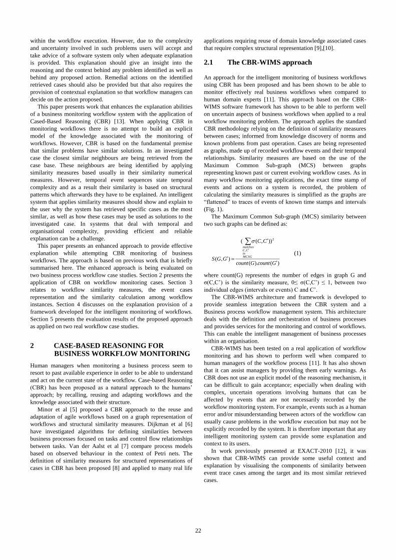
within the workflow execution. However, due to the complexity
and uncertainty involved in such problems users will accept and
take advice of a software system only when adequate explanation
is provided. This explanation should give an insight into the
reasoning and the context behind any problem identified as well as
behind any proposed action. Remedial actions on the identified
retrieved cases should also be provided but that also requires the
provision of contextual explanation so that workflow managers can
decide on the action proposed.
This paper presents work that enhances the explanation abilities
of a business monitoring workflow system with the application of
Cased-Based Reasoning (CBR) [13]. When applying CBR in
monitoring workflows there is no attempt to build an explicit
model of the knowledge associated with the monitoring of
workflows. However, CBR is based on the fundamental premise
that similar problems have similar solutions. In an investigated
case the closest similar neighbours are being retrieved from the
case base. These neighbours are being identified by applying
similarity measures based usually in their similarity numerical
measures. However, temporal event sequences state temporal
complexity and as a result their similarity is based on structural
patterns which afterwards they have to be explained. An intelligent
system that applies similarity measures should show and explain to
the user why the system has retrieved specific cases as the most
similar, as well as how these cases may be used as solutions to the
investigated case. In systems that deal with temporal and
organisational complexity, providing efficient and reliable
explanation can be a challenge.
This paper presents an enhanced approach to provide effective
explanation while attempting CBR monitoring of business
workflows. The approach is based on previous work that is briefly
summarised here. The enhanced approach is being evaluated on
two business process workflow case studies. Section 2 presents the
application of CBR on workflow monitoring cases. Section 3
relates to workflow similarity measures, the event cases
representation and the similarity calculation among workflow
instances. Section 4 discusses on the explanation provision of a
framework developed for the intelligent monitoring of workflows.
Section 5 presents the evaluation results of the proposed approach
as applied on two real workflow case studies.
2 CASE-BASED REASONING FOR BUSINESS WORKFLOW MONITORING
Human managers when monitoring a business process seem to
resort to past available experience in order to be able to understand
and act on the current state of the workflow. Case-based Reasoning
(CBR) has been proposed as a natural approach to the humans’
approach; by recalling, reusing and adapting workflows and the
knowledge associated with their structure.
Minor et al [5] proposed a CBR approach to the reuse and
adaptation of agile workflows based on a graph representation of
workflows and structural similarity measures. Dijkman et al [6]
have investigated algorithms for defining similarities between
business processes focused on tasks and control flow relationships
between tasks. Van der Aalst et al [7] compare process models
based on observed behaviour in the context of Petri nets. The
definition of similarity measures for structured representations of
cases in CBR has been proposed [8] and applied to many real life
applications requiring reuse of domain knowledge associated cases
that require complex structural representation [9],[10].
2.1 The CBR-WIMS approach
An approach for the intelligent monitoring of business workflows
using CBR has been proposed and has been shown to be able to
monitor effectively real business workflows when compared to
human domain experts [11]. This approach based on the CBR-
WIMS software framework has shown to be able to perform well
on uncertain aspects of business workflows when applied to a real
workflow monitoring problem. The approach applies the standard
CBR methodology relying on the definition of similarity measures
between cases; informed from knowledge discovery of norms and
known problems from past operation. Cases are being represented
as graphs, made up of recorded workflow events and their temporal
relationships. Similarity measures are based on the use of the
Maximum Common Sub-graph (MCS) between graphs
representing known past or current evolving workflow cases. As in
many workflow monitoring applications, the exact time stamp of
events and actions on a system is recorded, the problem of
calculating the similarity measures is simplified as the graphs are
“flattened” to traces of events of known time stamps and intervals
(Fig. 1).
The Maximum Common Sub-graph (MCS) similarity between
two such graphs can be defined as:
(1)
where count(G) represents the number of edges in graph G and
σ(C,C’) is the similarity measure, 0≤ σ(C,C’) ≤ 1, between two
individual edges (intervals or events) C and C’.
The CBR-WIMS architecture and framework is developed to
provide seamless integration between the CBR system and a
Business process workflow management system. This architecture
deals with the definition and orchestration of business processes
and provides services for the monitoring and control of workflows.
This can enable the intelligent management of business processes
within an organisation.
CBR-WIMS has been tested on a real application of workflow
monitoring and has shown to perform well when compared to
human managers of the workflow process [11]. It has also shown
that it can assist managers by providing them early warnings. As
CBR does not use an explicit model of the reasoning mechanism, it
can be difficult to gain acceptance; especially when dealing with
complex, uncertain operations involving humans that can be
affected by events that are not necessarily recorded by the
workflow monitoring system. For example, events such as a human
error and/or misunderstanding between actors of the workflow can
usually cause problems in the workflow execution but may not be
explicitly recorded by the system. It is therefore important that any
intelligent monitoring system can provide some explanation and
context to its users.
In work previously presented at EXACT-2010 [12], it was
shown that CBR-WIMS can provide some useful context and
explanation by visualising the components of similarity between
event trace cases among the target and its most similar retrieved
cases.
)().(
)),((
),(
,
2
GcountGcount
CC
GGSMCSGin
CCmatches
22
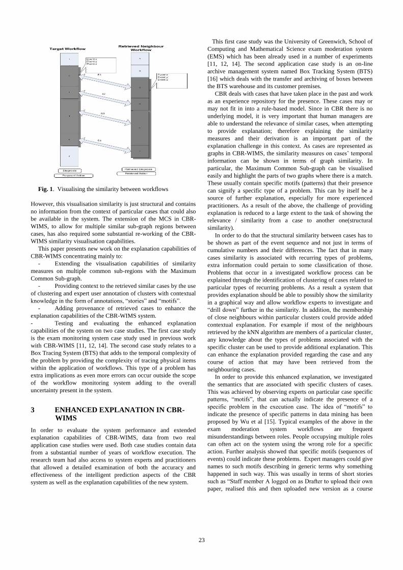
Fig. 1. Visualising the similarity between workflows
However, this visualisation similarity is just structural and contains
no information from the context of particular cases that could also
be available in the system. The extension of the MCS in CBR-
WIMS, to allow for multiple similar sub-graph regions between
cases, has also required some substantial re-working of the CBR-
WIMS similarity visualisation capabilities.
This paper presents new work on the explanation capabilities of
CBR-WIMS concentrating mainly to:
- Extending the visualisation capabilities of similarity
measures on multiple common sub-regions with the Maximum
Common Sub-graph.
- Providing context to the retrieved similar cases by the use
of clustering and expert user annotation of clusters with contextual
knowledge in the form of annotations, “stories” and “motifs”.
- Adding provenance of retrieved cases to enhance the
explanation capabilities of the CBR-WIMS system.
- Testing and evaluating the enhanced explanation
capabilities of the system on two case studies. The first case study
is the exam monitoring system case study used in previous work
with CBR-WIMS [11, 12, 14]. The second case study relates to a
Box Tracing System (BTS) that adds to the temporal complexity of
the problem by providing the complexity of tracing physical items
within the application of workflows. This type of a problem has
extra implications as even more errors can occur outside the scope
of the workflow monitoring system adding to the overall
uncertainty present in the system.
3 ENHANCED EXPLANATION IN CBR-WIMS
In order to evaluate the system performance and extended
explanation capabilities of CBR-WIMS, data from two real
application case studies were used. Both case studies contain data
from a substantial number of years of workflow execution. The
research team had also access to system experts and practitioners
that allowed a detailed examination of both the accuracy and
effectiveness of the intelligent prediction aspects of the CBR
system as well as the explanation capabilities of the new system.
This first case study was the University of Greenwich, School of
Computing and Mathematical Science exam moderation system
(EMS) which has been already used in a number of experiments
[11, 12, 14]. The second application case study is an on-line
archive management system named Box Tracking System (BTS)
[16] which deals with the transfer and archiving of boxes between
the BTS warehouse and its customer premises.
CBR deals with cases that have taken place in the past and work
as an experience repository for the presence. These cases may or
may not fit in into a rule-based model. Since in CBR there is no
underlying model, it is very important that human managers are
able to understand the relevance of similar cases, when attempting
to provide explanation; therefore explaining the similarity
measures and their derivation is an important part of the
explanation challenge in this context. As cases are represented as
graphs in CBR-WIMS, the similarity measures on cases’ temporal
information can be shown in terms of graph similarity. In
particular, the Maximum Common Sub-graph can be visualised
easily and highlight the parts of two graphs where there is a match.
These usually contain specific motifs (patterns) that their presence
can signify a specific type of a problem. This can by itself be a
source of further explanation, especially for more experienced
practitioners. As a result of the above, the challenge of providing
explanation is reduced to a large extent to the task of showing the
relevance / similarity from a case to another one(structural
similarity).
In order to do that the structural similarity between cases has to
be shown as part of the event sequence and not just in terms of
cumulative numbers and their differences. The fact that in many
cases similarity is associated with recurring types of problems,
extra information could pertain to some classification of those.
Problems that occur in a investigated workflow process can be
explained through the identification of clustering of cases related to
particular types of recurring problems. As a result a system that
provides explanation should be able to possibly show the similarity
in a graphical way and allow workflow experts to investigate and
“drill down” further in the similarity. In addition, the membership
of close neighbours within particular clusters could provide added
contextual explanation. For example if most of the neighbours
retrieved by the kNN algorithm are members of a particular cluster,
any knowledge about the types of problems associated with the
specific cluster can be used to provide additional explanation. This
can enhance the explanation provided regarding the case and any
course of action that may have been retrieved from the
neighbouring cases.
In order to provide this enhanced explanation, we investigated
the semantics that are associated with specific clusters of cases.
This was achieved by observing experts on particular case specific
patterns, “motifs”, that can actually indicate the presence of a
specific problem in the execution case. The idea of “motifs” to
indicate the presence of specific patterns in data mining has been
proposed by Wu et al [15]. Typical examples of the above in the
exam moderation system workflows are frequent
misunderstandings between roles. People occupying multiple roles
can often act on the system using the wrong role for a specific
action. Further analysis showed that specific motifs (sequences of
events) could indicate these problems. Expert managers could give
names to such motifs describing in generic terms why something
happened in such way. This was usually in terms of short stories
such as “Staff member A logged on as Drafter to upload their own
paper, realised this and then uploaded new version as a course
23
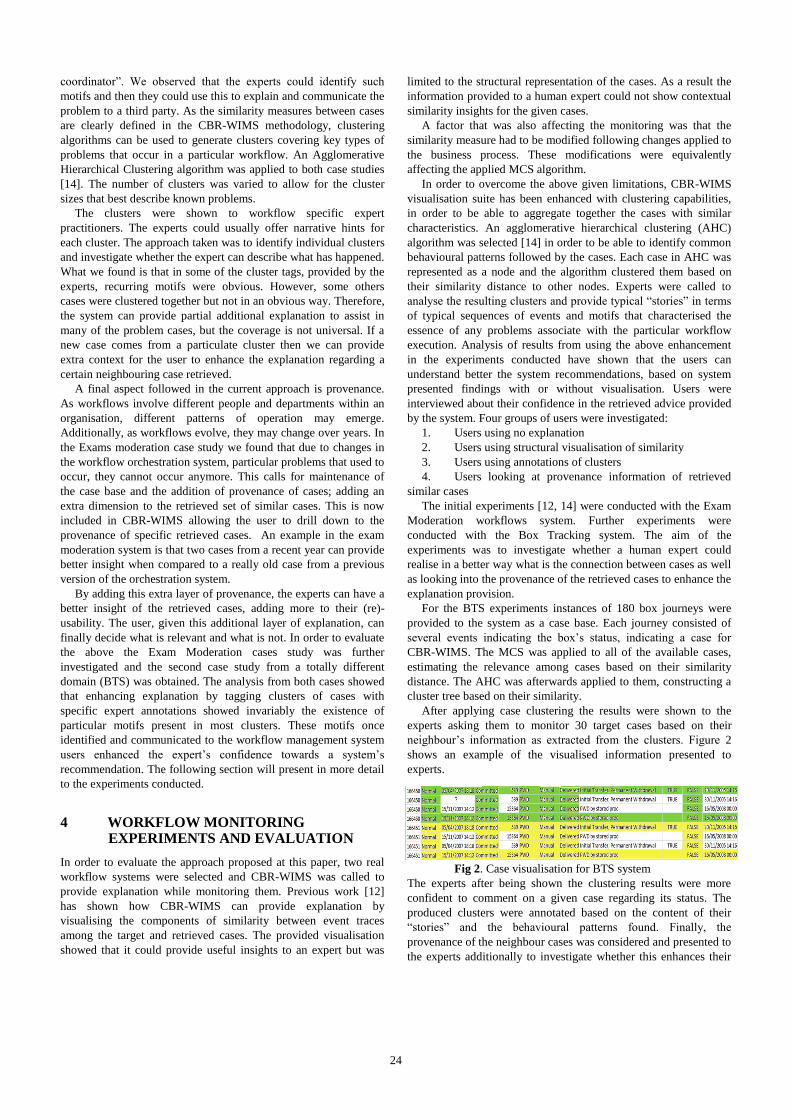
coordinator”. We observed that the experts could identify such
motifs and then they could use this to explain and communicate the
problem to a third party. As the similarity measures between cases
are clearly defined in the CBR-WIMS methodology, clustering
algorithms can be used to generate clusters covering key types of
problems that occur in a particular workflow. An Agglomerative
Hierarchical Clustering algorithm was applied to both case studies
[14]. The number of clusters was varied to allow for the cluster
sizes that best describe known problems.
The clusters were shown to workflow specific expert
practitioners. The experts could usually offer narrative hints for
each cluster. The approach taken was to identify individual clusters
and investigate whether the expert can describe what has happened.
What we found is that in some of the cluster tags, provided by the
experts, recurring motifs were obvious. However, some others
cases were clustered together but not in an obvious way. Therefore,
the system can provide partial additional explanation to assist in
many of the problem cases, but the coverage is not universal. If a
new case comes from a particulate cluster then we can provide
extra context for the user to enhance the explanation regarding a
certain neighbouring case retrieved.
A final aspect followed in the current approach is provenance.
As workflows involve different people and departments within an
organisation, different patterns of operation may emerge.
Additionally, as workflows evolve, they may change over years. In
the Exams moderation case study we found that due to changes in
the workflow orchestration system, particular problems that used to
occur, they cannot occur anymore. This calls for maintenance of
the case base and the addition of provenance of cases; adding an
extra dimension to the retrieved set of similar cases. This is now
included in CBR-WIMS allowing the user to drill down to the
provenance of specific retrieved cases. An example in the exam
moderation system is that two cases from a recent year can provide
better insight when compared to a really old case from a previous
version of the orchestration system.
By adding this extra layer of provenance, the experts can have a
better insight of the retrieved cases, adding more to their (re)-
usability. The user, given this additional layer of explanation, can
finally decide what is relevant and what is not. In order to evaluate
the above the Exam Moderation cases study was further
investigated and the second case study from a totally different
domain (BTS) was obtained. The analysis from both cases showed
that enhancing explanation by tagging clusters of cases with
specific expert annotations showed invariably the existence of
particular motifs present in most clusters. These motifs once
identified and communicated to the workflow management system
users enhanced the expert’s confidence towards a system’s
recommendation. The following section will present in more detail
to the experiments conducted.
4 WORKFLOW MONITORING EXPERIMENTS AND EVALUATION
In order to evaluate the approach proposed at this paper, two real
workflow systems were selected and CBR-WIMS was called to
provide explanation while monitoring them. Previous work [12]
has shown how CBR-WIMS can provide explanation by
visualising the components of similarity between event traces
among the target and retrieved cases. The provided visualisation
showed that it could provide useful insights to an expert but was
limited to the structural representation of the cases. As a result the
information provided to a human expert could not show contextual
similarity insights for the given cases.
A factor that was also affecting the monitoring was that the
similarity measure had to be modified following changes applied to
the business process. These modifications were equivalently
affecting the applied MCS algorithm.
In order to overcome the above given limitations, CBR-WIMS
visualisation suite has been enhanced with clustering capabilities,
in order to be able to aggregate together the cases with similar
characteristics. An agglomerative hierarchical clustering (AHC)
algorithm was selected [14] in order to be able to identify common
behavioural patterns followed by the cases. Each case in AHC was
represented as a node and the algorithm clustered them based on
their similarity distance to other nodes. Experts were called to
analyse the resulting clusters and provide typical “stories” in terms
of typical sequences of events and motifs that characterised the
essence of any problems associate with the particular workflow
execution. Analysis of results from using the above enhancement
in the experiments conducted have shown that the users can
understand better the system recommendations, based on system
presented findings with or without visualisation. Users were
interviewed about their confidence in the retrieved advice provided
by the system. Four groups of users were investigated:
1. Users using no explanation
2. Users using structural visualisation of similarity
3. Users using annotations of clusters
4. Users looking at provenance information of retrieved
similar cases
The initial experiments [12, 14] were conducted with the Exam
Moderation workflows system. Further experiments were
conducted with the Box Tracking system. The aim of the
experiments was to investigate whether a human expert could
realise in a better way what is the connection between cases as well
as looking into the provenance of the retrieved cases to enhance the
explanation provision.
For the BTS experiments instances of 180 box journeys were
provided to the system as a case base. Each journey consisted of
several events indicating the box’s status, indicating a case for
CBR-WIMS. The MCS was applied to all of the available cases,
estimating the relevance among cases based on their similarity
distance. The AHC was afterwards applied to them, constructing a
cluster tree based on their similarity.
After applying case clustering the results were shown to the
experts asking them to monitor 30 target cases based on their
neighbour’s information as extracted from the clusters. Figure 2
shows an example of the visualised information presented to
experts.
Fig 2. Case visualisation for BTS system
The experts after being shown the clustering results were more
confident to comment on a given case regarding its status. The
produced clusters were annotated based on the content of their
“stories” and the behavioural patterns found. Finally, the
provenance of the neighbour cases was considered and presented to
the experts additionally to investigate whether this enhances their
24

level of confidence. By knowing the provenance the levels of
confidence were increased, helping in understanding better what
happened in the investigated case based on the neighbours’ past.
An interesting finding after looking into the provenance of the
cases was that it works in a different way across systems. When
looking into the provenance of the Exams Moderation System
(EMS) the cases were affected from the yearly period that they
were conducted, showing that cases from the same period are more
likely to be of use than those from different years. Also summer
resit exam cases were showing similar patterns with other past
summer resits so the provenance of a retrieved case was important
to the effectiveness of the CBR process. Finally, in this
investigation, the provenance of a case study in terms of the
academic department involved was shown to be important. As the
EMS allowed to be used by departments in slightly different ways,
the Mathematics department had chosen to draft exams in meetings
of tutors rather than individually. This created specific temporal
workflow execution patterns that precluded a set of problems from
occurring, but introduced the possibility of other scenarios. In this
context, the provenance of a case from that specific academic
department was shown to be important to understand emerging
patterns, but it was of practically no discriminatory use between the
other academic departments that all followed a similar work
pattern. However, in the case of BTS case the issue of provenance
was more related to the company showing different behavioural
patterns to company’s “loyal” customers compared to other “new”
ones.
Provenance has shown to be invariably important but relatively
different aspects were shown to be important across systems. As
provenance of retrieved cases is an extra feature available to CBR-
WIMS users “drilling down” into retrieved cases, it is left naturally
to the users to reason about the provenance information presented
to them. Interestingly enough, the experiments conducted, showed
that the gain in predictive effectiveness of the CBR system from
providing the additional provenance information was modest, but
when it came to filtering false positives it had an effect of nearly
50% reduction of false positives. This shows that provenance can
be very useful at filtering out retrieved cases that although
structurally similar to the investigated problem workflow
execution, may have a different context altogether.
5 CONCLUSIONS
This paper presents an approach towards the enhanced explanation
provision of monitored workflows. The investigated business
workflows contain incomplete temporal data as derived from the
case study systems’ operational logs. Their representation has been
conducted via graphs, based on their temporal relationships. This
paper has shown how the CBR-WIMS framework can incorporate
any investigated business workflow systems. Two case study
systems have been used and CBR-WIMS had applied similarity
measures between their instances using the MCS. Explanation
provision has been conducted using real data from past workflow
executions. The evaluation presented at this paper has shown that
the adopted approach can be applied to more than one enterprise
systems, enhancing the monitoring capabilities of human experts.
An expert by using the hierarchical clustering can follow a “drill-
down” approach aiming to extract useful system insights. As
shown from the conducted experiments this can be viable and
efficient, getting an idea of possible patterns of either problematic
or healthy system operations. Further work on the above will
concentrate on the cases’ provenance as well as how this could
enhance the monitoring capabilities. An investigation to another
workflow system would also be sought in order to inspect the given
opportunities for explanation patterns’ reuse along systems.
REFERENCES
[1] Business Process Management Initiative (BPMI): BPMN 2.0: OMG
Specification, January, 2011, http://www.omg.org/spec/BPMN/2.0/, accessed
May 2012.P. Atkin. Performance maximisation. INMOS Technical Note 17.
[2] IBM: Business process standards, Part 1: An introduction, 2007,
http://www.ibm.com/developerworks/websphere/library/techarticles/
0710_fasbinder/0710_fasbinder.html, accessed May 2012.
[3] Workflow Management Coalition (WfMC): XPDL 2.1 Complete
Specification (Updated Oct 10, 2008),
http://www.wfmc.org/xpdl.html, accessed April 2009.
[4] Michaelis, J. R., Ding, L., McGuinness, D. L. (2009). Towards the Explanation
of Workflows. In: Proceedings of the IJCAI 2009 Workshop on Explanation
Aware Computing (ExaCt).Pasadena,CA, US.
[5] Minor, M., Tartakovski, A. and Bergmann, R.: Representation and
Structure-Based Similarity Assessment for Agile Workflows, in
Weber, R., O. and Richter, M., M.(Eds) CBR Research and
Development, Proceedings of the 7th international conference on
Case-Based Reasoning, ICCBR 2007, Belfast, NI, UK, August 2007,
LNAI 4626, pp 224-238, Springer-Verlag, (2007).
[6] Dijkman, R.M., Dumas, M., Garcia-Banuelos, L. Graph matching
algorithms for business process model similarity search. In U. Dayal, J.
Eder (Eds.), Proc. of the 7th Int. conference on business process
management. (LNCS, Vol. 5701, pp. 48-63). Berlin: Springer. (2009).
[7] van der Aalst, W., Alves de Medeiros, A. K., Weijters, A : Process
Equivalence: Comparing two Process Models Based on Observed
Behavior, In Proc. Of BPM 2006, vol 4102 of LNCS, pp 129-144,
Springer, (2006).
[8] Bunke, H., Messmer, B.T.: Similarity Measures for Structured Representations.
In: Wess, S., Richter, M., Althoff, K.-D. (eds) Topics is Case-Based Reasoning.
LNCS, vol. 837, pp 106-118, Springer, Heidelberg (1994).
[9] Mileman, T., Knight, B., Petridis, M., Cowell, D., Ewer, J. (2002): Case-Based
Retrieval of 3-D shapes for the design of metal castings in Journal of Intelligent
Manufacturing, Kluwer. 13(1): 39-45; Feb 2002.
[10] Wolf, M., Petridis, M.: Measuring Similarity of Software Designs
using Graph Matching for CBR, In workshop proceedings of AISEW
2008 at ECAI 2008, Patras, Greece (2008).
[11] Kapetanakis, S., Petridis, M., Knight, B., Ma, J.,Bacon, L. : A Case
Based Reasoning Approach for the Monitoring of Business
Workflows, 18th International Conference on Case-Based Reasoning,
ICCBR 2010, Alessandria, Italy, LNAI (2010).
[12] Kapetanakis, S., Petridis, Ma, J., Bacon, L. (2010). Providing Explanations for
the Intelligent Monitoring of Business Workflows Using Case-Based
Reasoning. In Roth-Berghofer, T., Tintarev, N., Leake, D. B., Bahls, D. (eds.):
Proceedings of the Fifth International workshop on Explanation-aware
Computing ExaCt (ECAI 2010). Lisbon, Portugal.
[13] Kolodner, J. L. (1983). Reconstructive memory: A computer model.
Cognitive Science. 7 (4), pp. 281-328.
[14] Kapetanakis, S., Petridis, M., Ma, J., Knight, B., Bacon, L. (2011). Enhancing
Similarity Measures and Context Provision for the Intelligent Monitoring of
Business Processes in CBR-WIMS. In: 19th International Conference on Case
Based Reasoning, 12-15th September 2011, Greenwich, London.
[15] Wu, G., Harrigan, M., Cunningham, P. (2011). A Characterization of
Wikipedia Content Based on Motifs in the Edit Graph. UCD-CSI-
2011-02. School of Computer Science & Informatics, University
College Dublin. Dublin, Ireland.
[16] Kapetanakis, S. (2012). Intelligent Monitoring of Business Processes
using Case-based Reasoning. PhD Thesis. University of Greenwich.
UK.
25
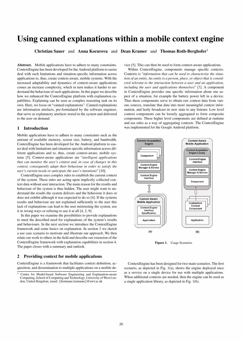
Using canned explanations within a mobile context engineChristian Sauer and Anna Kocurova and Dean Kramer and Thomas Roth-Berghofer1
Abstract. Mobile applications have to adhere to many constraints.ContextEngine has been developed for the Android platform to easierdeal with such limitations and situation-specific information acrossapplications to, thus, create context-aware, mobile systems. With theincreased adaptability and dynamics of context-aware applicationscomes an increase complexity, which in turn makes it harder to un-derstand the behaviour of such applications. In this paper we describehow we enhanced the ContextEngine platform with explanation ca-pabilities. Explaining can be seen as complex reasoning task on itsown. Here, we focus on “canned explanations”. Canned explanationsare information artefacts, pre-formulated by the software engineer,that serve as explanatory artefacts stored in the system and deliveredto the user on demand.
1 IntroductionMobile applications have to adhere to many constraints such as theamount of available memory, screen size, battery, and bandwidth.ContextEngine has been developed for the Android platform to eas-ier deal with limitations and situation-specific information across dif-ferent applications and to, thus, create context-aware, mobile sys-tems [5]. Context-aware applications are “intelligent applicationsthat can monitor the user’s context and, in case of changes in thiscontext, consequently adapt their behaviour in order to satisfy theuser’s current needs or anticipate the user’s intentions” [10].
ContextEngine uses complex rules to establish the current contextof the system. These rules are acting upon implicitly collected con-text data without user interaction. The main reason for the results andbehaviour of the system is thus hidden. The user might want to un-derstand the results the system delivers and the behaviour it does ordoes not exhibit although it was expected to do so [4]. If the systemsresults and behaviour are not explained sufficiently to the user thislack of explanations can lead to the user mistrusting the system, useit in wrong ways or refusing to use it at all [4, 2, 9].
In this paper we examine the possibilities to provide explanationsto meet the described need for explanations of the system’s resultsand behaviours. In the next section we introduce the ContextEngineframework and some basics on explanation. In section 3 we sketcha use case scenario to motivate and illustrate our approach. We thenrelate our work to others in the field and describe our extension of theContextEngine framework with explanation capabilities in section 4.The paper closes with a summary and outlook.
2 Providing context for mobile applicationsContextEngine is a framework that facilitates context definition, ac-quisition, and dissemination to multiple applications on a mobile de-1 Centre for Model-based Software Engineering and Explanation-aware
Computing, School of Computing and Technology, University of West Lon-don, United Kingdom, email: {firstname.lastname}@uwl.ac.uk
vice [5]. This can then be used to form context-aware applications.Within ContextEngine, components manage specific contexts.
Contexts is “information that can be used to characterise the situa-tion of an entity. An entity is a person, place, or object that is consid-ered relevant to the interaction between a user and an application,including the user and applications themselves” [7]. A componentin ContextEngine provides one specific information about one as-pect of a situation, for example the battery power left in a device.Thus these components serve to obtain raw context data from vari-ous sources, translate that data into more meaningful context infor-mation, and lastly broadcast its new state to any listener. Low levelcontext components can be loosely aggregated to form compositecomponents. These higher level components are defined at runtimeand use rules as a way of aggregating contexts. The ContextEnginewas implemented for the Google Android platform.
Figure 1. Usage Scenarios
ContextEngine has been designed for two main scenarios. The firstscenario, as depicted in Fig. 1(a), shows the engine deployed onceas a service on a single device for use with multiple applications.When additional contexts are needed, then the engine can be used asa single application library, as depicted in Fig. 1(b).
26
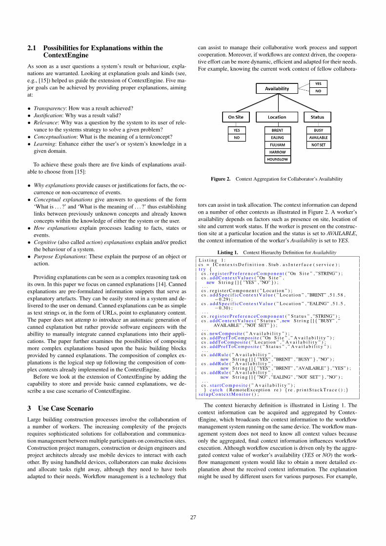
2.1 Possibilities for Explanations within theContextEngine
As soon as a user questions a system’s result or behaviour, expla-nations are warranted. Looking at explanation goals and kinds (see,e.g., [15]) helped us guide the extension of ContextEngine. Five ma-jor goals can be achieved by providing proper explanations, aimingat:
• Transparency: How was a result achieved?• Justification: Why was a result valid?• Relevance: Why was a question by the system to its user of rele-
vance to the systems strategy to solve a given problem?• Conceptualisation: What is the meaning of a term/concept?• Learning: Enhance either the user’s or system’s knowledge in a
given domain.
To achieve these goals there are five kinds of explanations avail-able to choose from [15]:
• Why explanations provide causes or justifications for facts, the oc-currence or non-occurrence of events.
• Conceptual explanations give answers to questions of the form‘What is . . . ?’ and ‘What is the meaning of . . . ?’ thus establishinglinks between previously unknown concepts and already knownconcepts within the knowledge of either the system or the user.
• How explanations explain processes leading to facts, states orevents.
• Cognitive (also called action) explanations explain and/or predictthe behaviour of a system.
• Purpose Explanations: These explain the purpose of an object oraction.
Providing explanations can be seen as a complex reasoning task onits own. In this paper we focus on canned explanations [14]. Cannedexplanations are pre-formulated information snippets that serve asexplanatory artefacts. They can be easily stored in a system and de-livered to the user on demand. Canned explanations can be as simpleas text strings or, in the form of URLs, point to explanatory content.The paper does not attemp to introduce an automatic generation ofcanned explanation but rather provide software engineers with theabillity to manually integrate canned explanations into their appli-cations. The paper further examines the possibilities of composingmore complex explanations based upon the basic building blocksprovided by canned explanations. The composition of complex ex-planations is the logical step up following the composition of com-plex contexts already implemented in the ContextEngine.
Before we look at the extension of ContextEngine by adding thecapability to store and provide basic canned explanations, we de-scribe a use case scenario of ContextEngine.
3 Use Case ScenarioLarge building construction processes involve the collaboration ofa number of workers. The increasing complexity of the projectsrequires sophisticated solutions for collaboration and communica-tion management between multiple participants on construction sites.Construction project managers, construction or design engineers andproject architects already use mobile devices to interact with eachother. By using handheld devices, collaborators can make decisionsand allocate tasks right away, although they need to have toolsadapted to their needs. Workflow management is a technology that
can assist to manage their collaborative work process and supportcooperation. Moreover, if workflows are context driven, the coopera-tive effort can be more dynamic, efficient and adapted for their needs.For example, knowing the current work context of fellow collabora-
Figure 2. Context Aggregation for Collaborator’s Availability
tors can assist in task allocation. The context information can dependon a number of other contexts as illustrated in Figure 2. A worker’savailability depends on factors such as presence on site, location ofsite and current work status. If the worker is present on the construc-tion site at a particular location and the status is set to AVAILABLE,the context information of the worker’s Availability is set to YES.
Listing 1. Context Hierarchy Definition for AvailabilityL i s t i n g 1 :c s = I C o n t e x t s D e f i n i t i o n . S tub . a s I n t e r f a c e ( s e r v i c e ) ;t r y {
cs . r e g i s t e r P r e f e r e n c e C o m p o n e n t ( ”On S i t e ” , ”STRING” ) ;c s . a d d C o n t e x t V a l u e s ( ”On S i t e ” ,
new S t r i n g [ ]{ ”YES” , ”NO” }) ;. . .c s . r e g i s t e r C o m p o n e n t ( ” L o c a t i o n ” ) ;c s . a d d S p e c i f i c C o n t e x t V a l u e ( ” L o c a t i o n ” , ”BRENT” , 5 1 . 5 8 ,
−0.29) ;c s . a d d S p e c i f i c C o n t e x t V a l u e ( ” L o c a t i o n ” , ”EALING” , 5 1 . 5 ,
−0.30) ;. . .c s . r e g i s t e r P r e f e r e n c e C o m p o n e n t ( ” S t a t u s ” , ”STRING” ) ;c s . a d d C o n t e x t V a l u e s ( ” S t a t u s ” , new S t r i n g [ ]{ ”BUSY” , ”
AVAILABLE” , ”NOT SET” }) ;. . .c s . newComposite ( ” A v a i l a b i l i t y ” ) ;c s . addPre fToCompos i t e ( ”On S i t e ” , ” A v a i l a b i l i t y ” ) ;c s . addToComposi te ( ” L o c a t i o n ” , ” A v a i l a b i l i t y ” ) ;c s . addPre fToCompos i t e ( ” S t a t u s ” , ” A v a i l a b i l i t y ” ) ;. . .c s . addRule ( ” A v a i l a b i l i t y ” ,
new S t r i n g [ ]{ ”YES” , ”BRENT” , ”BUSY” } , ”NO” ) ;c s . addRule ( ” A v a i l a b i l i t y ” ,
new S t r i n g [ ]{ ”YES” , ”BRENT” , ”AVAILABLE” } , ”YES” ) ;c s . addRule ( ” A v a i l a b i l i t y ” ,
new S t r i n g [ ]{ ”NO” , ”EALING” , ”NOT SET” } , ”NO” ) ;. . .c s . s t a r t C o m p o s i t e ( ” A v a i l a b i l i t y ” ) ;} c a t c h ( RemoteExcep t ion r e ) { r e . p r i n t S t a c k T r a c e ( ) ;}
s e t u p C o n t e x t M o n i t o r ( ) ;
The context hierarchy definition is illustrated in Listing 1. Thecontext information can be acquired and aggregated by Contex-tEngine, which broadcasts the context information to the workflowmanagement system running on the same device. The workflow man-agement system does not need to know all context values becauseonly the aggregated, final context information influences workflowexecution. Although workflow execution is driven only by the aggre-gated context value of worker’s availability (YES or NO) the work-flow management system would like to obtain a more detailed ex-planation about the received context information. The explanationmight be used by different users for various purposes. For example,
27
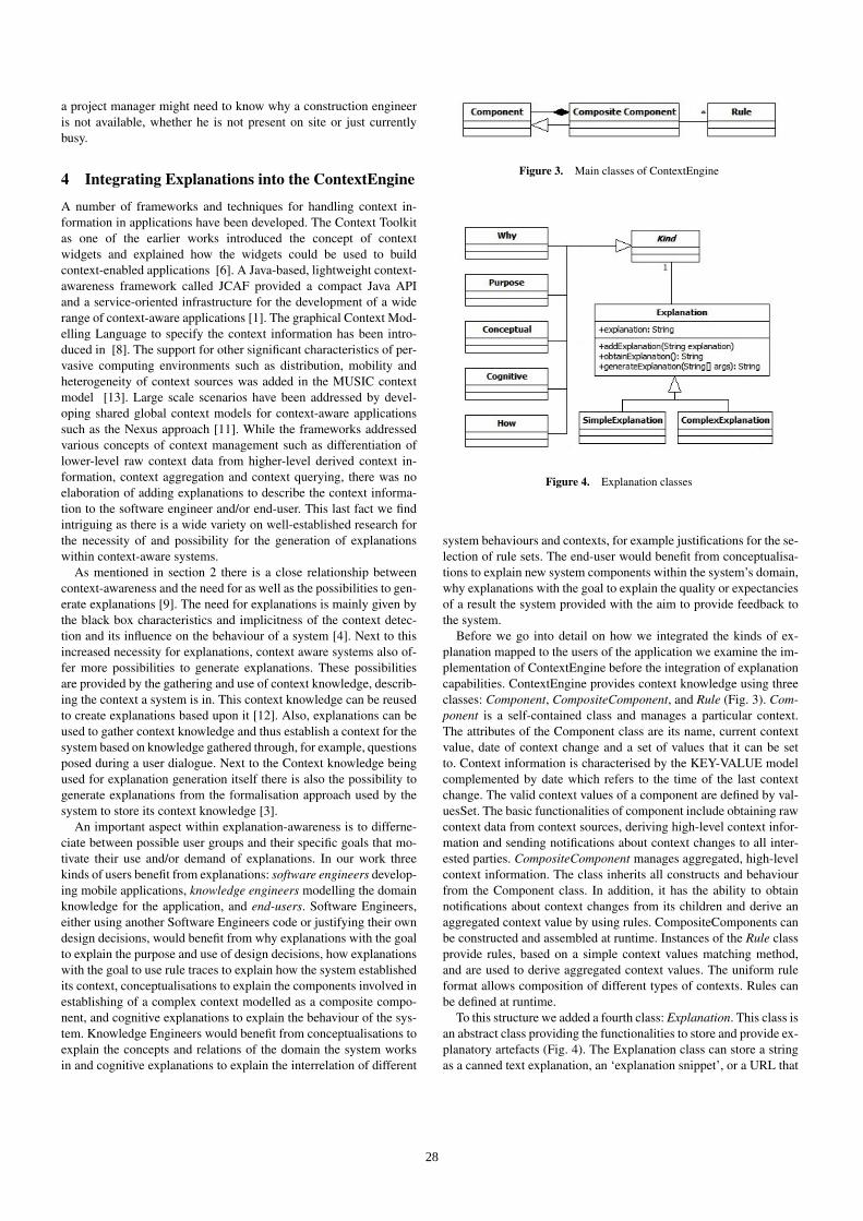
a project manager might need to know why a construction engineeris not available, whether he is not present on site or just currentlybusy.
4 Integrating Explanations into the ContextEngine
A number of frameworks and techniques for handling context in-formation in applications have been developed. The Context Toolkitas one of the earlier works introduced the concept of contextwidgets and explained how the widgets could be used to buildcontext-enabled applications [6]. A Java-based, lightweight context-awareness framework called JCAF provided a compact Java APIand a service-oriented infrastructure for the development of a widerange of context-aware applications [1]. The graphical Context Mod-elling Language to specify the context information has been intro-duced in [8]. The support for other significant characteristics of per-vasive computing environments such as distribution, mobility andheterogeneity of context sources was added in the MUSIC contextmodel [13]. Large scale scenarios have been addressed by devel-oping shared global context models for context-aware applicationssuch as the Nexus approach [11]. While the frameworks addressedvarious concepts of context management such as differentiation oflower-level raw context data from higher-level derived context in-formation, context aggregation and context querying, there was noelaboration of adding explanations to describe the context informa-tion to the software engineer and/or end-user. This last fact we findintriguing as there is a wide variety on well-established research forthe necessity of and possibility for the generation of explanationswithin context-aware systems.
As mentioned in section 2 there is a close relationship betweencontext-awareness and the need for as well as the possibilities to gen-erate explanations [9]. The need for explanations is mainly given bythe black box characteristics and implicitness of the context detec-tion and its influence on the behaviour of a system [4]. Next to thisincreased necessity for explanations, context aware systems also of-fer more possibilities to generate explanations. These possibilitiesare provided by the gathering and use of context knowledge, describ-ing the context a system is in. This context knowledge can be reusedto create explanations based upon it [12]. Also, explanations can beused to gather context knowledge and thus establish a context for thesystem based on knowledge gathered through, for example, questionsposed during a user dialogue. Next to the Context knowledge beingused for explanation generation itself there is also the possibility togenerate explanations from the formalisation approach used by thesystem to store its context knowledge [3].
An important aspect within explanation-awareness is to differne-ciate between possible user groups and their specific goals that mo-tivate their use and/or demand of explanations. In our work threekinds of users benefit from explanations: software engineers develop-ing mobile applications, knowledge engineers modelling the domainknowledge for the application, and end-users. Software Engineers,either using another Software Engineers code or justifying their owndesign decisions, would benefit from why explanations with the goalto explain the purpose and use of design decisions, how explanationswith the goal to use rule traces to explain how the system establishedits context, conceptualisations to explain the components involved inestablishing of a complex context modelled as a composite compo-nent, and cognitive explanations to explain the behaviour of the sys-tem. Knowledge Engineers would benefit from conceptualisations toexplain the concepts and relations of the domain the system worksin and cognitive explanations to explain the interrelation of different
Figure 3. Main classes of ContextEngine
Figure 4. Explanation classes
system behaviours and contexts, for example justifications for the se-lection of rule sets. The end-user would benefit from conceptualisa-tions to explain new system components within the system’s domain,why explanations with the goal to explain the quality or expectanciesof a result the system provided with the aim to provide feedback tothe system.
Before we go into detail on how we integrated the kinds of ex-planation mapped to the users of the application we examine the im-plementation of ContextEngine before the integration of explanationcapabilities. ContextEngine provides context knowledge using threeclasses: Component, CompositeComponent, and Rule (Fig. 3). Com-ponent is a self-contained class and manages a particular context.The attributes of the Component class are its name, current contextvalue, date of context change and a set of values that it can be setto. Context information is characterised by the KEY-VALUE modelcomplemented by date which refers to the time of the last contextchange. The valid context values of a component are defined by val-uesSet. The basic functionalities of component include obtaining rawcontext data from context sources, deriving high-level context infor-mation and sending notifications about context changes to all inter-ested parties. CompositeComponent manages aggregated, high-levelcontext information. The class inherits all constructs and behaviourfrom the Component class. In addition, it has the ability to obtainnotifications about context changes from its children and derive anaggregated context value by using rules. CompositeComponents canbe constructed and assembled at runtime. Instances of the Rule classprovide rules, based on a simple context values matching method,and are used to derive aggregated context values. The uniform ruleformat allows composition of different types of contexts. Rules canbe defined at runtime.
To this structure we added a fourth class: Explanation. This class isan abstract class providing the functionalities to store and provide ex-planatory artefacts (Fig. 4). The Explanation class can store a stringas a canned text explanation, an ‘explanation snippet’, or a URL that
28
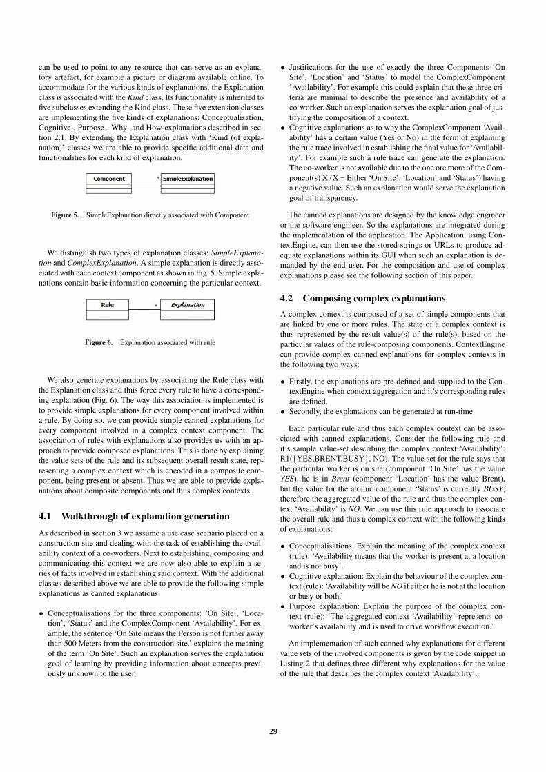
can be used to point to any resource that can serve as an explana-tory artefact, for example a picture or diagram available online. Toaccommodate for the various kinds of explanations, the Explanationclass is associated with the Kind class. Its functionality is inherited tofive subclasses extending the Kind class. These five extension classesare implementing the five kinds of explanations: Conceptualisation,Cognitive-, Purpose-, Why- and How-explanations described in sec-tion 2.1. By extending the Explanation class with ‘Kind (of expla-nation)’ classes we are able to provide specific additional data andfunctionalities for each kind of explanation.
Figure 5. SimpleExplanation directly associated with Component
We distinguish two types of explanation classes: SimpleExplana-tion and ComplexExplanation. A simple explanation is directly asso-ciated with each context component as shown in Fig. 5. Simple expla-nations contain basic information concerning the particular context.
Figure 6. Explanation associated with rule
We also generate explanations by associating the Rule class withthe Explanation class and thus force every rule to have a correspond-ing explanation (Fig. 6). The way this association is implemented isto provide simple explanations for every component involved withina rule. By doing so, we can provide simple canned explanations forevery component involved in a complex context component. Theassociation of rules with explanations also provides us with an ap-proach to provide composed explanations. This is done by explainingthe value sets of the rule and its subsequent overall result state, rep-resenting a complex context which is encoded in a composite com-ponent, being present or absent. Thus we are able to provide expla-nations about composite components and thus complex contexts.
4.1 Walkthrough of explanation generationAs described in section 3 we assume a use case scenario placed on aconstruction site and dealing with the task of establishing the avail-ability context of a co-workers. Next to establishing, composing andcommunicating this context we are now also able to explain a se-ries of facts involved in establishing said context. With the additionalclasses described above we are able to provide the following simpleexplanations as canned explanations:
• Conceptualisations for the three components: ‘On Site’, ‘Loca-tion’, ‘Status’ and the ComplexComponent ‘Availability’. For ex-ample, the sentence ‘On Site means the Person is not further awaythan 500 Meters from the construction site.’ explains the meaningof the term ’On Site’. Such an explanation serves the explanationgoal of learning by providing information about concepts previ-ously unknown to the user.
• Justifications for the use of exactly the three Components ‘OnSite’, ‘Location’ and ‘Status’ to model the ComplexComponent’Availability’. For example this could explain that these three cri-teria are minimal to describe the presence and availability of aco-worker. Such an explanation serves the explanation goal of jus-tifying the composition of a context.
• Cognitive explanations as to why the ComplexComponent ‘Avail-ability’ has a certain value (Yes or No) in the form of explainingthe rule trace involved in establishing the final value for ‘Availabil-ity’. For example such a rule trace can generate the explanation:The co-worker is not available due to the one ore more of the Com-ponent(s) X (X = Either ‘On Site’, ‘Location’ and ‘Status’) havinga negative value. Such an explanation would serve the explanationgoal of transparency.
The canned explanations are designed by the knowledge engineeror the software engineer. So the explanations are integrated duringthe implementation of the application. The Application, using Con-textEngine, can then use the stored strings or URLs to produce ad-equate explanations within its GUI when such an explanation is de-manded by the end user. For the composition and use of complexexplanations please see the following section of this paper.
4.2 Composing complex explanationsA complex context is composed of a set of simple components thatare linked by one or more rules. The state of a complex context isthus represented by the result value(s) of the rule(s), based on theparticular values of the rule-composing components. ContextEnginecan provide complex canned explanations for complex contexts inthe following two ways:
• Firstly, the explanations are pre-defined and supplied to the Con-textEngine when context aggregation and it’s corresponding rulesare defined.
• Secondly, the explanations can be generated at run-time.
Each particular rule and thus each complex context can be asso-ciated with canned explanations. Consider the following rule andit’s sample value-set describing the complex context ‘Availability’:R1({YES,BRENT,BUSY}, NO). The value set for the rule says thatthe particular worker is on site (component ‘On Site’ has the valueYES), he is in Brent (component ‘Location’ has the value Brent),but the value for the atomic component ‘Status’ is currently BUSY,therefore the aggregated value of the rule and thus the complex con-text ‘Availability’ is NO. We can use this rule approach to associatethe overall rule and thus a complex context with the following kindsof explanations:
• Conceptualisations: Explain the meaning of the complex context(rule): ‘Availability means that the worker is present at a locationand is not busy’.
• Cognitive explanation: Explain the behaviour of the complex con-text (rule): ‘Availability will be NO if either he is not at the locationor busy or both.’
• Purpose explanation: Explain the purpose of the complex con-text (rule): ‘The aggregated context ‘Availability’ represents co-worker’s availability and is used to drive workflow execution.’
An implementation of such canned why explanations for differentvalue sets of the involved components is given by the code snippet inListing 2 that defines three different why explanations for the valueof the rule that describes the complex context ‘Availability’.
29
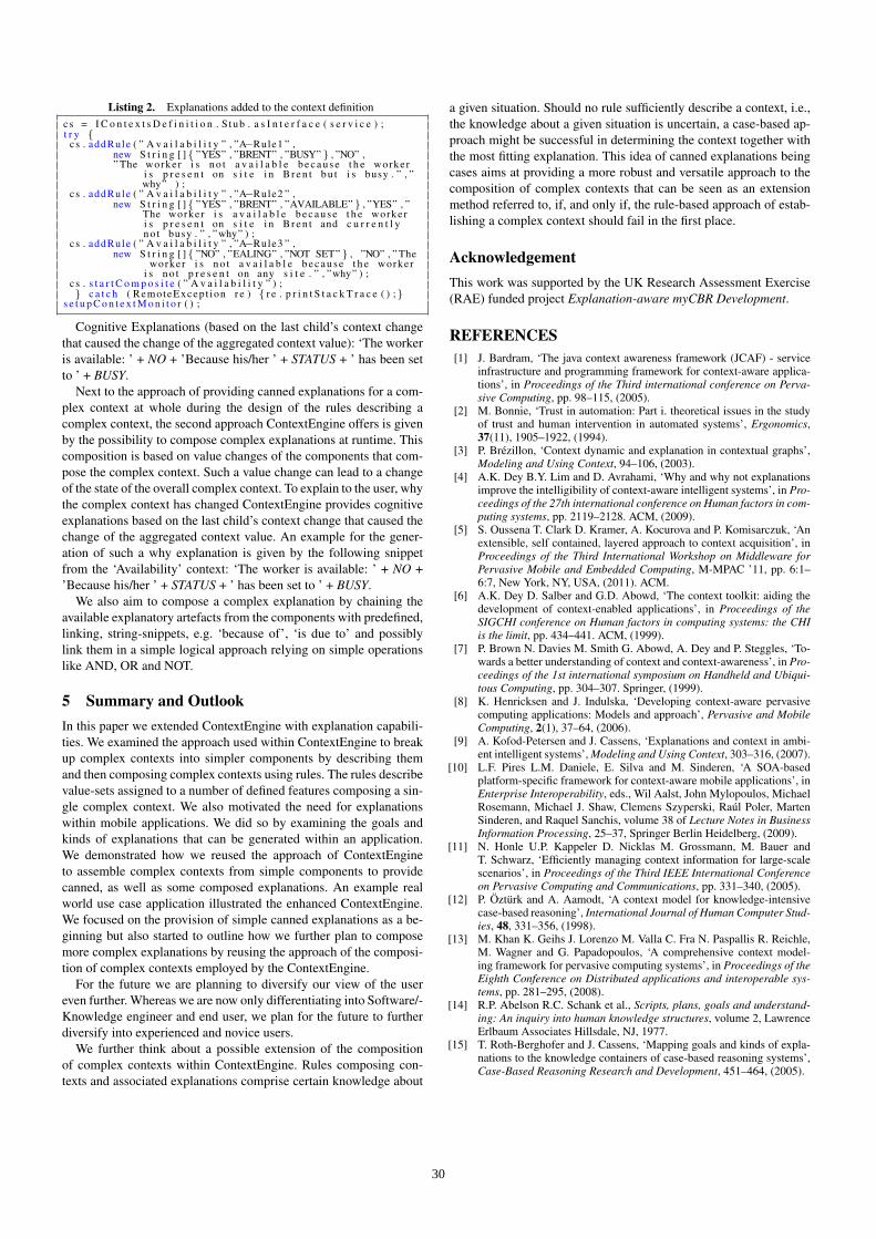
Listing 2. Explanations added to the context definitioncs = I C o n t e x t s D e f i n i t i o n . S tub . a s I n t e r f a c e ( s e r v i c e ) ;t r y {
cs . addRule ( ” A v a i l a b i l i t y ” , ”A−Rule1 ” ,new S t r i n g [ ]{ ”YES” , ”BRENT” , ”BUSY” } , ”NO” ,” The worker i s n o t a v a i l a b l e b e c a u s e t h e worker
i s p r e s e n t on s i t e i n B r e n t b u t i s busy . ” , ”why” ) ;
c s . addRule ( ” A v a i l a b i l i t y ” , ”A−Rule2 ” ,new S t r i n g [ ]{ ”YES” , ”BRENT” , ”AVAILABLE” } , ”YES” , ”
The worker i s a v a i l a b l e b e c a u s e t h e workeri s p r e s e n t on s i t e i n B r e n t and c u r r e n t l yn o t busy . ” , ”why” ) ;
c s . addRule ( ” A v a i l a b i l i t y ” , ”A−Rule3 ” ,new S t r i n g [ ]{ ”NO” , ”EALING” , ”NOT SET” } , ”NO” , ” The
worker i s n o t a v a i l a b l e b e c a u s e t h e workeri s n o t p r e s e n t on any s i t e . ” , ”why” ) ;
c s . s t a r t C o m p o s i t e ( ” A v a i l a b i l i t y ” ) ;} c a t c h ( RemoteExcep t ion r e ) { r e . p r i n t S t a c k T r a c e ( ) ;}
s e t u p C o n t e x t M o n i t o r ( ) ;
Cognitive Explanations (based on the last child’s context changethat caused the change of the aggregated context value): ‘The workeris available: ’ + NO + ’Because his/her ’ + STATUS + ’ has been setto ’ + BUSY.
Next to the approach of providing canned explanations for a com-plex context at whole during the design of the rules describing acomplex context, the second approach ContextEngine offers is givenby the possibility to compose complex explanations at runtime. Thiscomposition is based on value changes of the components that com-pose the complex context. Such a value change can lead to a changeof the state of the overall complex context. To explain to the user, whythe complex context has changed ContextEngine provides cognitiveexplanations based on the last child’s context change that caused thechange of the aggregated context value. An example for the gener-ation of such a why explanation is given by the following snippetfrom the ‘Availability’ context: ‘The worker is available: ’ + NO +’Because his/her ’ + STATUS + ’ has been set to ’ + BUSY.
We also aim to compose a complex explanation by chaining theavailable explanatory artefacts from the components with predefined,linking, string-snippets, e.g. ‘because of’, ‘is due to’ and possiblylink them in a simple logical approach relying on simple operationslike AND, OR and NOT.
5 Summary and OutlookIn this paper we extended ContextEngine with explanation capabili-ties. We examined the approach used within ContextEngine to breakup complex contexts into simpler components by describing themand then composing complex contexts using rules. The rules describevalue-sets assigned to a number of defined features composing a sin-gle complex context. We also motivated the need for explanationswithin mobile applications. We did so by examining the goals andkinds of explanations that can be generated within an application.We demonstrated how we reused the approach of ContextEngineto assemble complex contexts from simple components to providecanned, as well as some composed explanations. An example realworld use case application illustrated the enhanced ContextEngine.We focused on the provision of simple canned explanations as a be-ginning but also started to outline how we further plan to composemore complex explanations by reusing the approach of the composi-tion of complex contexts employed by the ContextEngine.
For the future we are planning to diversify our view of the usereven further. Whereas we are now only differentiating into Software/-Knowledge engineer and end user, we plan for the future to furtherdiversify into experienced and novice users.
We further think about a possible extension of the compositionof complex contexts within ContextEngine. Rules composing con-texts and associated explanations comprise certain knowledge about
a given situation. Should no rule sufficiently describe a context, i.e.,the knowledge about a given situation is uncertain, a case-based ap-proach might be successful in determining the context together withthe most fitting explanation. This idea of canned explanations beingcases aims at providing a more robust and versatile approach to thecomposition of complex contexts that can be seen as an extensionmethod referred to, if, and only if, the rule-based approach of estab-lishing a complex context should fail in the first place.
AcknowledgementThis work was supported by the UK Research Assessment Exercise(RAE) funded project Explanation-aware myCBR Development.
REFERENCES[1] J. Bardram, ‘The java context awareness framework (JCAF) - service
infrastructure and programming framework for context-aware applica-tions’, in Proceedings of the Third international conference on Perva-sive Computing, pp. 98–115, (2005).
[2] M. Bonnie, ‘Trust in automation: Part i. theoretical issues in the studyof trust and human intervention in automated systems’, Ergonomics,37(11), 1905–1922, (1994).
[3] P. Brezillon, ‘Context dynamic and explanation in contextual graphs’,Modeling and Using Context, 94–106, (2003).
[4] A.K. Dey B.Y. Lim and D. Avrahami, ‘Why and why not explanationsimprove the intelligibility of context-aware intelligent systems’, in Pro-ceedings of the 27th international conference on Human factors in com-puting systems, pp. 2119–2128. ACM, (2009).
[5] S. Oussena T. Clark D. Kramer, A. Kocurova and P. Komisarczuk, ‘Anextensible, self contained, layered approach to context acquisition’, inProceedings of the Third International Workshop on Middleware forPervasive Mobile and Embedded Computing, M-MPAC ’11, pp. 6:1–6:7, New York, NY, USA, (2011). ACM.
[6] A.K. Dey D. Salber and G.D. Abowd, ‘The context toolkit: aiding thedevelopment of context-enabled applications’, in Proceedings of theSIGCHI conference on Human factors in computing systems: the CHIis the limit, pp. 434–441. ACM, (1999).
[7] P. Brown N. Davies M. Smith G. Abowd, A. Dey and P. Steggles, ‘To-wards a better understanding of context and context-awareness’, in Pro-ceedings of the 1st international symposium on Handheld and Ubiqui-tous Computing, pp. 304–307. Springer, (1999).
[8] K. Henricksen and J. Indulska, ‘Developing context-aware pervasivecomputing applications: Models and approach’, Pervasive and MobileComputing, 2(1), 37–64, (2006).
[9] A. Kofod-Petersen and J. Cassens, ‘Explanations and context in ambi-ent intelligent systems’, Modeling and Using Context, 303–316, (2007).
[10] L.F. Pires L.M. Daniele, E. Silva and M. Sinderen, ‘A SOA-basedplatform-specific framework for context-aware mobile applications’, inEnterprise Interoperability, eds., Wil Aalst, John Mylopoulos, MichaelRosemann, Michael J. Shaw, Clemens Szyperski, Raul Poler, MartenSinderen, and Raquel Sanchis, volume 38 of Lecture Notes in BusinessInformation Processing, 25–37, Springer Berlin Heidelberg, (2009).
[11] N. Honle U.P. Kappeler D. Nicklas M. Grossmann, M. Bauer andT. Schwarz, ‘Efficiently managing context information for large-scalescenarios’, in Proceedings of the Third IEEE International Conferenceon Pervasive Computing and Communications, pp. 331–340, (2005).
[12] P. Ozturk and A. Aamodt, ‘A context model for knowledge-intensivecase-based reasoning’, International Journal of Human Computer Stud-ies, 48, 331–356, (1998).
[13] M. Khan K. Geihs J. Lorenzo M. Valla C. Fra N. Paspallis R. Reichle,M. Wagner and G. Papadopoulos, ‘A comprehensive context model-ing framework for pervasive computing systems’, in Proceedings of theEighth Conference on Distributed applications and interoperable sys-tems, pp. 281–295, (2008).
[14] R.P. Abelson R.C. Schank et al., Scripts, plans, goals and understand-ing: An inquiry into human knowledge structures, volume 2, LawrenceErlbaum Associates Hillsdale, NJ, 1977.
[15] T. Roth-Berghofer and J. Cassens, ‘Mapping goals and kinds of expla-nations to the knowledge containers of case-based reasoning systems’,Case-Based Reasoning Research and Development, 451–464, (2005).
30

Author Index
Bader, Sebastian 1Bex, Floris 6Budzynska, Katarzyna 6
Dengel, Andreas 11
Forcher, Bjorn 11
Gandon, Fabien 16Gillmann, Michael 11
Hasan, Rakebul 16
Kapetanakis, Stelios 21Kocurova, Anna 26Kramer, Dean 26
Petersen, Nils 11Petridis, Miltos 21
Roth-Berghofer, Thomas 26
Sauer, Christian Severin 26
Tuncer, Zeynep 11
Walton, Douglas 6