Embed Size (px)
Citation preview

Journal of Engineering Volume 19 December 2013 Number 12
1531
Experimental Study of Pre-Cast Reinforced Concrete Deep Beams (Hallow Core section) Retrofitting with Carbon Fiber Reinforced
Polymer (CFRP)
Lecturer Dr. Hadi Nasir Ghadhban Mohammed AL-Miliki Civil Engineering Department College of Engineering, AL-Mustansiriya, University.
e-mail: [email protected] ABSTRACT:
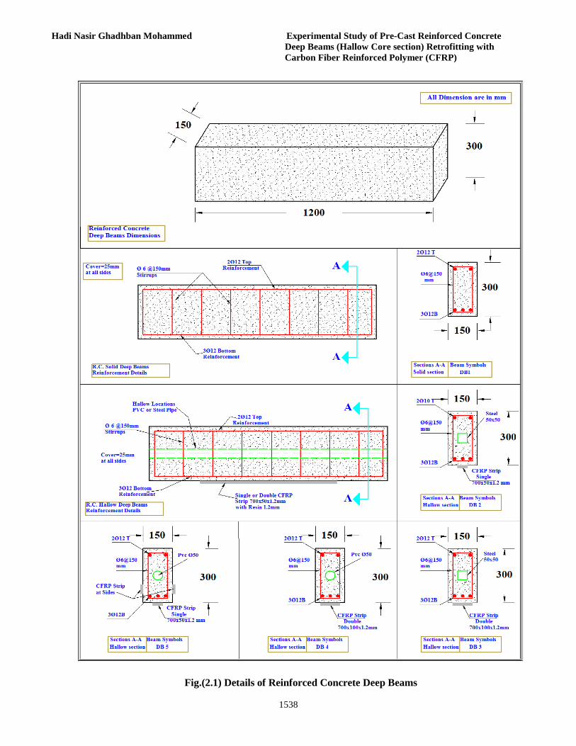
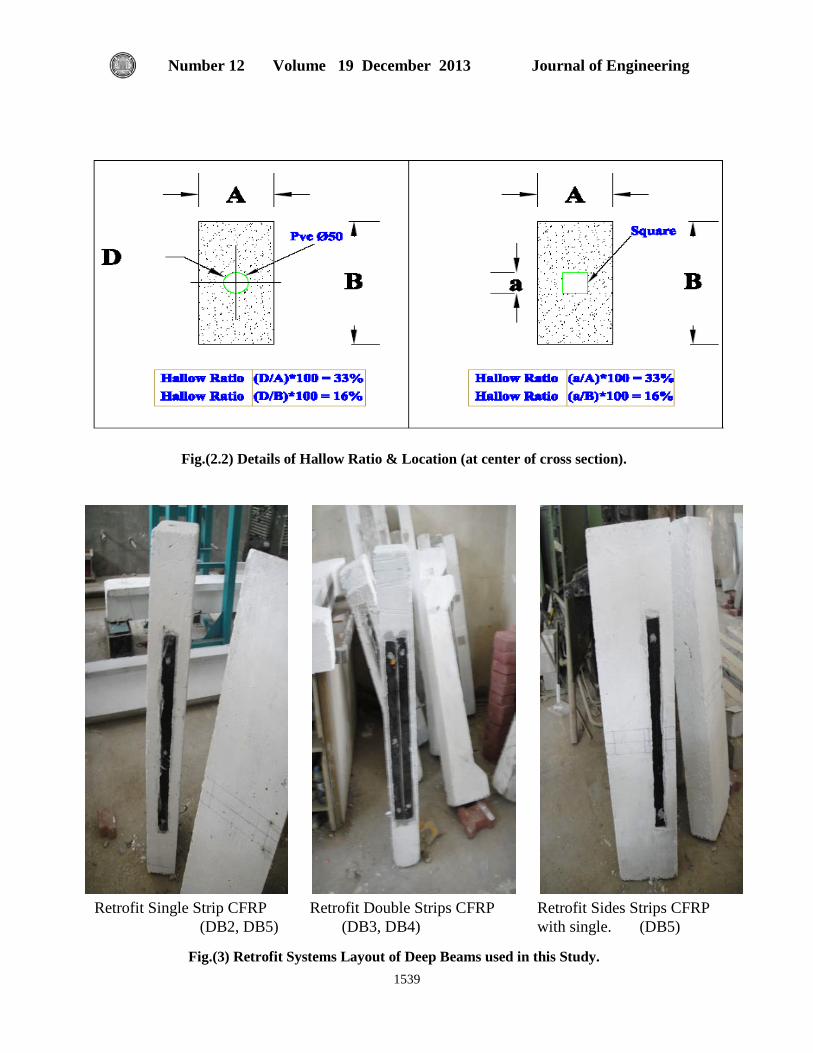
Experimental programs based test results has been used as a means to find out the response of individual elements of structure. In the present study involves investigated behavior of five reinforced concrete deep beams of dimension (length 1200 x height 300 x width150mm) under two points concentrated load with shear span to depth ratio of (1.52), four of these beams with hallow core and retrofit with carbon fiber reinforced polymer CFRP (with single or double or sides Strips). Two shapes of hallow are investigated (circle and square section) to evaluated the response of beams in case experimental behavior. Test on simply supported beam was performed in the laboratory & load-deflection, strain of concrete data and crack pattern of those five reinforced concrete beams was recorded. Parametric studies are also conducted in this study includes the effect of hallow opening (shapes and materials), and CFRP ratio (single, double strips and side horizontal stirrups). Comparisons of test results from experimental data are based on load capacity, deflection, crack pattern and strain of concrete for all beams. From this comparison it was found that hallow effect on strength capacity i.e. decrease by about (13%) and increased in deflection and strain by about (18%, 24%) respectively compared with solid section. Also find that CFRP give more enhancements in loading capacity by about (33 to 66%) and decreased deflection for same applied load by about (26%). Test results that show when sides of beams retrofit with CFRP strip against horizontal shear increased strength by about by (20%). Finally the using double CFRP strips for hallow section gives equivalent or more than strength capacity of solid section. KEY WORDS: Hallow Core, Deep beams, First Crack, Deflection, CFRP (Single, Double & Sides) and Crack Pattern.
الدراسة العملية للعتبات الخرسانيةالمسلحة العميقة المسبقة الصب والمجوفة المقطع كاربون البوليميريةالمعززة بألياف ال
محمد المالكيم.د. هادي ناصر غضبان
الجامعة المستنصرية / كليه الهندسة
:الخالصة سلوك ستخدم لمعرفة االستجابة للعناصرالمختلفة من المنشاء. هذه الدراسة شملت تحريتالبرامج العملية التي اساسها نتائج الفحوصات
ملم) تحت حملين مركزيين ونسبة 150ملم والعرض 300ملم واالرتفاع 1200د (الطول خمس عتبات خرسانية مسلحة عميقة وبابعا). اربع من هذه العتبات كانت مجوفة المقطع ومعززة بالياف الكاربون البوليميرية (مفردة او 1.52فضاء القص إلى العمق كان (
ستجابة لهذه العتبات عند الفحص العملي. الفحص تم في مزدوجة او جانبية). تم تحري شكلين من التجويف (مربع ودائري) لتقييم االالمختبر وبيانات الحمل الهطول واالنفعال للخرسانة وانماط التشقق للعتبات الخرسانية المسلحة العميقة تم تسجيلة. المتغيرات في هذه
ليمرية. المقارنة للنتائج العملية تمت على اساس الدراسة أخذت تأثير كل من التجويف (شكلة ومادتة) وتاثير التعزيز بالياف الكاربون البوقابلية التحمل ومقدار الهطول وانماط التشقق وانفعال الخرسانة. من خالل المقارنة تم ايجاد ان المقطع المجوف يقلل من قابلية التحمل
الكاربون البوليميرية تعطي %) على التوالي. كذلك وجد ان الياف 24%،18%،13ويزداد الهطول واالنفعال للخرسانة بمقدار (%). نتائج الفحص بينت عند 26%) وتقلل الهطول المقابل لنفس االحمال بمقدار (66-%33تحسينات أكثر في قابلية التحمل بحدود(
1532
Hadi Nasir Ghadhban Mohammed Experimental Study of Pre-Cast Reinforced Concrete Deep Beams (Hallow Core section) Retrofitting with Carbon Fiber Reinforced Polymer (CFRP)
. اخيرا %)20استخدام الياف الكاربون البوليميرية لتقوية جوانب العتبات لمقاومة قوى القص االفقية تزيد من مقاومة العتبات بمقدار ( استخدام صفائح مزدوجة من الياف الكاربون البوليميرية ولمقطع مجوف تعطي قابلية تحمل مكافئة او اكبر من العتبات الغير مجوفة .
: اللب المجوف ،العتبات العميقة ،التشقق األولي ،الهطول ،ألياف الكاربون البوليميرية (مفردة ومزدوجة الكلمات الرئيسية
التشقق وجانبية)،أنماط .
INTRODUCTION Concrete structural components exist in
buildings and bridges in different forms. Understanding the response of these components during loading is crucial to the development of an overall efficient and safe structure. Different methods have been utilized to study the response of structural components. Experimental based testing has been widely used as a means to analyze individual elements and the effects of concrete strength under loading. While this is a method that produces real life response, it is extremely time consuming and the use of materials can be quite costly. Long span bridges with very large size beams are constructed to accommodate high moment and shear demands. In particular, bridge beams with hallow section are designed in accordance with serve and maintain all part and mechanical or electrical i.e. all services. Many parameters may influence the overall hollow beams response such as: the shape of the section, the amount of the longitudinal and transverse reinforcement, the cross section thickness, effect of loading and finally the material strength of concrete and reinforcement. This research program focuses on circular and rectangular hollow cross sections and investigates the beams behavior under a state of two point concentrated load. Since the end of the Second World War, many advanced military technologies and products have been transferred to the civil engineering industry. FRP applied to structure retrofitting is one of the most successfully transferred technologies. During the last decades, the use of FRP has gained increasing popularity due to several properties such as: high strength to weight ratio; corrosion resistance; ease and speed of application; minimal change of cross-sections; possibility of installation without interruption of structure functions. For these reasons, FRP has been widely used in the retrofitting and strengthening
of reinforced concrete structures, especially in regions under high seismic risk. 2. IMPORTANCE OF STUDY:
The objective of this study was to investigate and evaluate the use of hallow section that give same load carrying capacity of solid beam section, also to show effect of shear reinforcing, hollow materials (PVC or Steel) and CFRP on load carrying capacity, deflection, strain crack pattern and failure mode. At summery the evaluating is compared based on load, deflection, strain and crack patterns for both section solid or hallow section. 3. METHODOLOGY: The experimental investigation involves the following: 1. Mix design of concrete for desired strength 2. Casting of beams with same proportion as concrete cylinder 3. Test of concrete cylinder at 28 days 4. Test of mild steel 5. Appling CFRP Strip after 28days 6. Test of beams after 2 weeks from applying CFRP Strips with resin. 4. EXPERIMENTAL PROGRAM:
Experimental program consist of test five R.C. beams, four with hallow core retrofit with CFRP with different parameters. The experimental program was conducted in the structural laboratory of the Civil Engineering Department at College of Engineering at the University of AL-Mustansiriya. The test beams dimensions of (length 1200 x height 300 and width 150mm) and properties are shown in Table (1). All beams were simply supported at bottom edges over clear length of (1100mm) and effective depth of (263mm). All specimens of shear span to depth ratio “a/d” equal to (1.52).
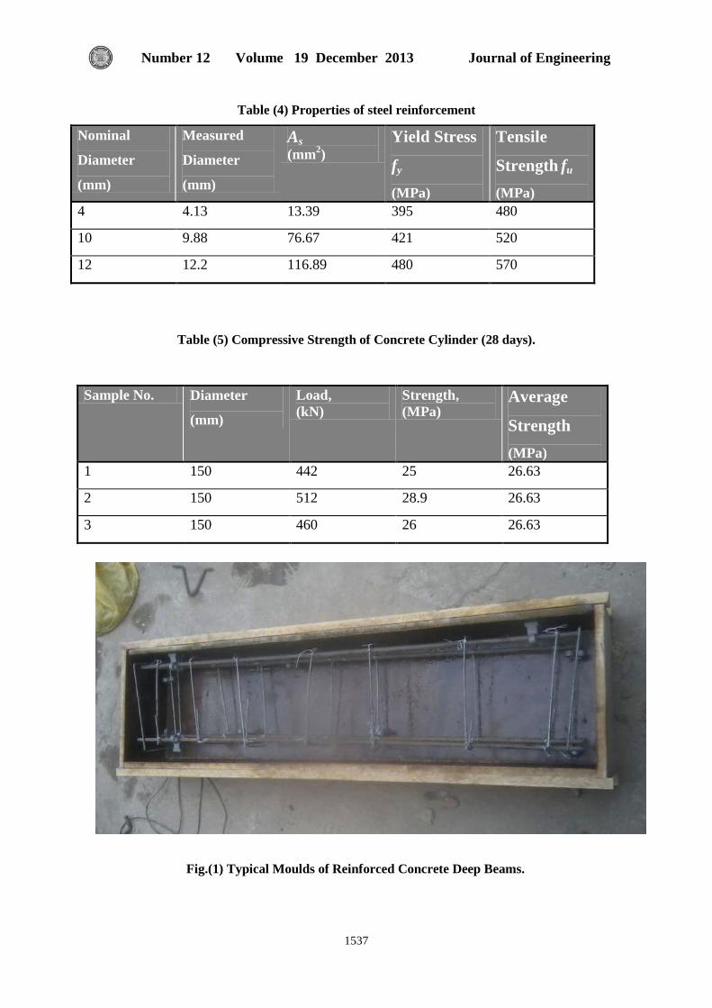
A schematic representation and photographs of the moulds and test setup and instrumentation are shown in Figs.(1,2,3&4).
Journal of Engineering Volume 19 December 2013 Number 12
1533
After the specimen is placed in position, load was applied at the top face of beam by two points concentrated as shown in Fig.(4). The load was increased gradually at increments of (10 kN). The deflections were measured at center of specimens at each load increments using digital dial gauge accuracy of (0.01). The strain in concrete also measured at mid span with distance between centers of demec are (100mm) as shown in Fig.(4). Test was carried on continued till failure. Failure mode and crack patterns were recorded.
The mixing ratio is bases on some series test carried on trail mixed to give the compressive strength of cylinder concrete in range about (27 MPa). The mixing ratio that used in this study is (cement 1: sand 1.5: gravel 3) as shown in Table (2). The deep beams retrofit with CFRP at three layouts i.e. one strip, double strips and sides strips as shown in Figs.(2 & 3) each strip of dimension ( length 700 x width 50 x thick 1.2 mm), Four of reinforced concrete deep beams were retrofit by CFRP (Carbon fiber strip Sika CarboDurS512) applied with resin (Sikadur-30). The typical characteristic properties of CFRP are shown in Table (3). The resin system that was used to bond the CFRP Strip over the bottom and two side regions of beams in this work was the epoxy resin made of two parts, resin and hardener. The properties of the resin are shown in Table (3) “Arockiasamy”. The use of make hole of diameter (150mm) at CFRP strips for all retrofit with CFRP led to not fail of CFRP, due to give good interlocking or good anchorage between CFRP and Resin and give good technique to construct. The main effect of these holes is to increase the reliability and repeatability of the failure behaviors to avoid failure of CFRP. 4.1The Process of Installation Procedures of CFRP Strip.
“Nimnim”, CFRP Strips were installed onto the concrete surface by manual lay-up in two steps. First, the primer was applied to the concrete surface. Next, the putty was used to level the surface. Then, the saturated, followed by the carbon fiber sheet and push lightly by hand applied. The components of the strengthening system are illustrated in Figs.(2 &
3) and the installation details of CFRP sheets are as follows: 1. Surface Preparation. Round the edges of specimens at the positions of strips. Next, sandblast the concrete surface until the surface of the concrete should be free of loose and unsound materials. 2. Application of the Primer resin. Apply a layer of epoxy-based primer to the prepared concrete surface using a short nap roller to penetrate the concrete pores and to provide an improved substrate for the saturating resin. 3. Application of the Putty. After the primer has become tack-free, apply a thin layer of putty using a trowel to level the concrete surface and to patch the small holes. 4. Application of Fiber Sheets. Each fiber sheet is measured and pre-cut prior to installation. Each sheet is then placed on the concrete surface and gently pressed into the primer resin. Prior to removing the backing paper, a trowel is used to remove any air void. After the backing paper is removed, a ribbed roller is rolled in the fiber direction to facilitate impregnation by separating the fibers.
5. TESTING PROCEDURE AND
TESTING EQUIPMENTS: The beams were tested after complete
curing of concrete 28 days and after 2 weeks from apply CFRP composite materials to retrofit of hallow reinforced concrete deep beams to gives equivalents section that give same or more capacity of solid deep beams. These where tested under static loading conditions using a universal testing machine of capacity 3000 kN. Testing machine was used to apply the load by two concentrated points. Each deep beams of the clear spans of 1100mm to be tested was simply supported by two ends roller, two-inch diameter steel rollers located two inches from each end of the beam. A steel plate was inserted between the concrete and the steel roller to ensure that local failure did not occur at the support. For the point loading condition, a one-inch diameter steel ball bearing suspended between two steel plates was used to transfer the load evenly from the universal testing machine to the surface of the test specimen. To measured deflection used digital dial gauge of accuracy (0.01mm) at mid span under the beam, while

1534
Hadi Nasir Ghadhban Mohammed Experimental Study of Pre-Cast Reinforced Concrete Deep Beams (Hallow Core section) Retrofitting with Carbon Fiber Reinforced Polymer (CFRP)
strain of concrete measuring using demec points of distance (100mm) between centers of its and (50mm) from concrete edges . Fig.(4) shows the typical set-up used for the two-point loading conditions.
6. TEST RESULTS OF
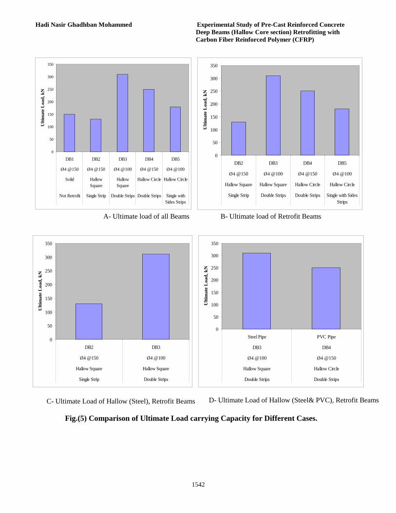
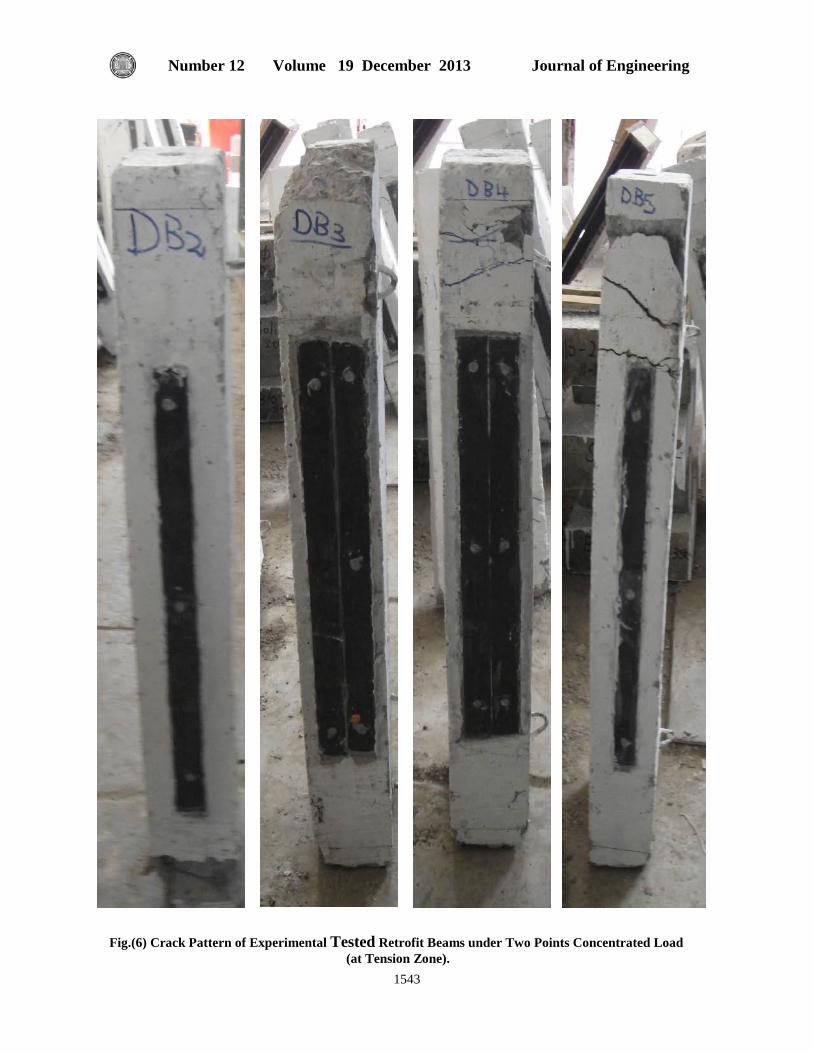
EXPERIMENTAL SPECIMENS: Test results for each specimen are reported. Table (4) shows the measured cracking loads, ultimate loads, vertical displacement at mid span of beams and strain of concrete at top and bottom zone of all the specimens. The comparison between results are shown in Fig.(5) Figs.(6 & 7) shows the crack patterns of all specimens. The load deflection curves at points of mid span are illustrated in Figs.(8).
6.1 First Crack and Ultimate Load: The first crack load and ultimate
carrying capacity increased when used CFRP Strips to retrofit these beams, and when used steel square pipe to construct hallow zone and also led to give decreased in corresponding deflection. While the using pipe( PVC & Steel) to construct the hallow section decrease the load capacity and increase in corresponding deflection for the same properties. Also when used double strips of CFRP to retrofit of beams give more load capacity and decrease in deflection. These results can show in Table (4) and comparison shown in Fig.(5). 6.2 Crack Patterns of Tested Beams:
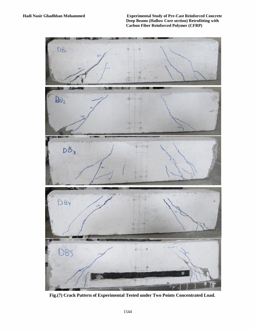
The failure of these Beams has occurred at the near support of the hollow beams, in Correspondence with Cores due to the change from the solid section of the deep beams core to the hollow section. The failure was particularly brittle with sudden crush of the concrete in compression and concrete cover spalling nears supports Figs.(6&7). Fig.(7) show that crack begins increased of its width with increased applied load, also the retrofit flexural zone (tension face at bottom of all beams) give more enhancement of flexural. Capacity and therefore shear stress concentrated at shear zone led’s to shear failure. For all
beams retrofit with CFRP no failure mode of (debonding or peeling off or …etc). Finally the retrofit of flexural zone led to that beam fail in shear. 6.3 Load Deflection and Strain Curves Behavior:
The comparison based on load-deflection at mid span at bottom of beams, which describe the behaviors of all tested specimens are shown in Fig.(8). The load-deflection curves are almost linear at the beginning of the loading, then getting inclination before the ultimate load. While the strain through depth are shown in Fig.(9). 7. CONCLUSIONS:
A total of five reinforced concrete deep beams were tested. One solid and the other of hallow (square steel or circle PVC pipes). All deep beams subjected to two points concentrated load, and shear span to depth ratio “a/d” equal to (1.52).Based on the test results for the range of the studied factors the following conclusions and observations can be made:
1. The existence of hallow (opening) at the center core part of the beam (along the beam) when used steel pipe retrofit with single strips of CFRP influenced the ultimate load value more than the existence of the opening at other case when retrofit with double strips or single strip with sides strips of CFRP of different hallow sections, where in the first case the load decreased by about 13% compared to the solid beam, although this beam retrofit with single strips of CFRP, while in the other case the load increased at different rates. This is because hallow in the first case intersects the flow of the force.
2. The first crack occurred at a load ranging from about 30 % to 36 % of the ultimate load depending on many factors (solid, hallow and Retrofit by CFRP).
3. Diagonal cracks at almost 45 degree formed within the third part at end near supports (shear span).
4. After shear crack occurred, the load decreased slowly, which attribute to shear interlocking and dowel action. Near ultimate load, the load is increased in a slow rate, while there is big increase in deflection.

Journal of Engineering Volume 19 December 2013 Number 12
1535
5. All tested deep beams exhibited a shear failure mode of behavior characterized by diagonal cracks at almost 45 degree.
6. The experimental test result shown that presence of CFRP has important rule to increase the strength capacity even in the linear stage by about (33 to 66.7%) for single and double strip of CFRP.
7. The construction of reinforced hollow deep beams is feasible since they possess load carrying capacity approximately equal or more to that of reinforced concrete solid deep beams when used PVC pipe with retrofit single and side CFRP strips i.e. specimen of (DB5).
8. Also it is recommended to used Steel or PVC pipe to construct hallow section of Deep beams specimens(DB3& DB4) retrofit with double CFRP Strips at tension zone, these are feasible since they possess load carrying capacity approximately more to that of reinforced concrete solid deep beams by about (106.7%, 66.7%) respectively.
9. The use of make hole of diameter (150mm) at CFRP strips for all retrofit with CFRP led to not fail of CFRP, due to give good interlocking or good anchorage between CFRP and Resin and give good technique to construct. The main effect of these holes is to increase the reliability and repeatability of the failure behaviors to avoid failure of CFRP.
10. Ductility is increased by about (390 to 2170 kN.mm ) in all cases for flexural loadings capacity when using CFRP to retrofit the reinforced concrete deep beams. 8. REFERENCES: Nilson, A. H. , Darwin, D. and Dolan, C. W. , "Design of Concrete Structure" McGraw-Hill Book Company 2006. British Standard Institution (BS 8110), (1997) "Code of Practice for Design and Construction" British Standard Institution Part 1, London. ACI 318M – 11: "Building Code Requirements for Reinforced Concrete, "ACI Committee 318M, 2011. ASTM 2006, " American Society for Testing and Materials ".
Nimnim, H. T., "Structural Behavior of Ferrocement Box-Beams," M. Sc., thesis, University of Technology, 1993. AASHTO LRFD (2005): "Bridge Design Specifications and Commentary (3rd Ed.) ". Washington, DC: American Association of State and Highway Transportation Officials. Ashour, A.F., (2000),"Shear Capacity of Reinforced Concrete Deep Beams", ASCE Structural Journal, September 2000, Vol. 126, No. 9, pp. 1045-1052. Darwish, M.N., (1998),"Reinforced High Strength Concrete Deep Beams: Effects of Web Reinforcement", Proceedings of the Eighth International Colloquium on Structural and Geotechnical Engineering, Cairo, Egypt 1998, pp. 99-112. Austin, S., Robins, P., Pan, Y. (1995). "Tensile Bond Testing of Concrete Repairs.” Materials and Structures, 28(179), 249-259. Oehlers, D. J., & Bradford, M. A. (1995). "Composite Steel and Concrete Structural Members". Kidlington, Oxford, U.K.: Elsevier Science, Ltd. Arockiasamy, M., Amer, A. and Shahawy, M. (1996) "Concrete beams and slabs retrofitted with CFRP laminates", Proceedings of the Eleventh Conference on Engineering Mechanics, ASCE, New York, USA, pp776-779. ACI committee 440.2R-02, "Guide for the Design and Construction of Externally Bonded FRP Systems for Strengthening Concrete Structures" American Concrete Institute, Michigan, USA, 2002,p.45.
1536
Hadi Nasir Ghadhban Mohammed Experimental Study of Pre-Cast Reinforced Concrete Deep Beams (Hallow Core section) Retrofitting with Carbon Fiber Reinforced Polymer (CFRP)
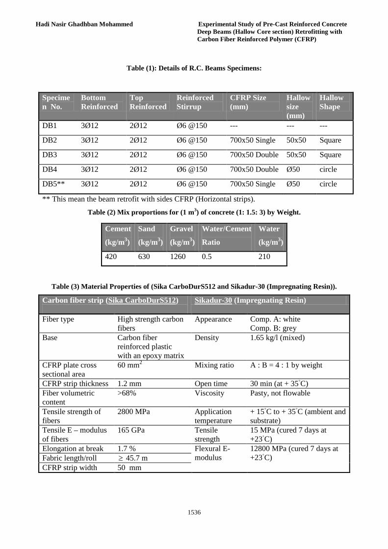
Table (1): Details of R.C. Beams Specimens:
** This mean the beam retrofit with sides CFRP (Horizontal strips).
Table (2) Mix proportions for (1 m3) of concrete (1: 1.5: 3) by Weight.
Table (3) Material Properties of (Sika CarboDurS512 and Sikadur-30 (Impregnating Resin)).
Carbon fiber strip (Sika CarboDurS512)
Sikadur-30 (Impregnating Resin)
Fiber type High strength carbon fibers
Appearance Comp. A: white Comp. B: grey
Base
Carbon fiber reinforced plastic with an epoxy matrix
Density 1.65 kg/l (mixed)
CFRP plate cross sectional area
60 mm2 Mixing ratio A : B = 4 : 1 by weight
CFRP strip thickness 1.2 mm Open time 30 min (at + 35◦C) Fiber volumetric content
>68% Viscosity Pasty, not flowable
Tensile strength of fibers
2800 MPa Application temperature
+ 15◦C to + 35◦C (ambient and substrate)
Tensile E – modulus of fibers
165 GPa Tensile strength
15 MPa (cured 7 days at +23◦C)
Elongation at break 1.7 % Flexural E-modulus
12800 MPa (cured 7 days at +23◦C) Fabric length/roll ≥ 45.7 m
CFRP strip width 50 mm
Specimen No.
Bottom Reinforced
Top Reinforced
Reinforced Stirrup
CFRP Size (mm)
Hallow size (mm)
Hallow Shape
DB1 3Ø12 2Ø12 Ø6 @150 --- --- ---
DB2 3Ø12 2Ø12 Ø6 @150 700x50 Single 50x50 Square
DB3 3Ø12 2Ø12 Ø6 @150 700x50 Double 50x50 Square
DB4 3Ø12 2Ø12 Ø6 @150 700x50 Double Ø50 circle
DB5** 3Ø12 2Ø12 Ø6 @150 700x50 Single Ø50 circle
Cement
(kg/m3)
Sand
(kg/m3)
Gravel
(kg/m3)
Water/Cement
Ratio
Water
(kg/m3)
420 630 1260 0.5 210
Journal of Engineering Volume 19 December 2013 Number 12
1537
Table (4) Properties of steel reinforcement
Tensile
Strength fu (MPa)
Yield Stress
fy (MPa)
As (mm2)
Measured
Diameter
(mm)
Nominal
Diameter
(mm)
480 395 13.39 4.13 4
520 421 76.67 9.88 10
570 480 116.89 12.2 12
Table (5) Compressive Strength of Concrete Cylinder (28 days).
Average
Strength (MPa)
Strength, (MPa)
Load, (kN)
Diameter
(mm)
Sample No.
26.63 25 442 150 1
26.63 28.9 512 150 2
26.63 26 460 150 3
Fig.(1) Typical Moulds of Reinforced Concrete Deep Beams.
1538
Hadi Nasir Ghadhban Mohammed Experimental Study of Pre-Cast Reinforced Concrete Deep Beams (Hallow Core section) Retrofitting with Carbon Fiber Reinforced Polymer (CFRP)
Fig.(2.1) Details of Reinforced Concrete Deep Beams
Journal of Engineering Volume 19 December 2013 Number 12
1539
Fig.(3) Retrofit Systems Layout of Deep Beams used in this Study.
Retrofit Single Strip CFRP (DB2, DB5)
Retrofit Double Strips CFRP (DB3, DB4)
Retrofit Sides Strips CFRP with single. (DB5)
Fig.(2.2) Details of Hallow Ratio & Location (at center of cross section).

1540
Hadi Nasir Ghadhban Mohammed Experimental Study of Pre-Cast Reinforced Concrete Deep Beams (Hallow Core section) Retrofitting with Carbon Fiber Reinforced Polymer (CFRP)
Fig.(4) Arrangement Specimens of Two-Point Loading and Instrumentation.

Journal of Engineering Volume 19 December 2013 Number 12
1541
Table (4) Fist Crack, Ultimate Load and deflections
* This beam reference beam. *** This mean decrease in failure load although this beam retrofit with CFRP due to hallow section and the CFRP ratio not enough to give strength capacity equivalent to solid deep beams.
Beam No.
First Crack Load kN
Deflection mm at First Crack Load
Failure Load, kN
Deflection mm at Failure Load
Increased in Failure Load%
Failure mode
DB1* 45 0.95 150 8.43 ---- Shear
DB2 40 1.34 130 6.02 -13.3*** Shear
DB3 90 1.01 310 14.31 106.7 Shear
DB4 83 0.81 250 8.67 66.7 Shear
DB5 65 0.76 180 8.82 20 Shear
1542
Hadi Nasir Ghadhban Mohammed Experimental Study of Pre-Cast Reinforced Concrete Deep Beams (Hallow Core section) Retrofitting with Carbon Fiber Reinforced Polymer (CFRP)
Fig.(5) Comparison of Ultimate Load carrying Capacity for Different Cases.
A- Ultimate load of all Beams B- Ultimate load of Retrofit Beams
0
50
100
150
200
250
300
350
DB1 DB2 DB3 DB4 DB5
Ø4 @150 Ø4 @150 Ø4 @100 Ø4 @150 Ø4 @100
Solid HallowSquare
HallowSquare
Hallow Circle Hallow Circle
Not Retrofit Single Strip Double Strips Double Strips Single withSides Strips
Ulti
mat
e L
oad,
kN
0
50
100
150
200
250
300
350
DB2 DB3 DB4 DB5
Ø4 @150 Ø4 @100 Ø4 @150 Ø4 @100
Hallow Square Hallow Square Hallow Circle Hallow Circle
Single Strip Double Strips Double Strips Single with SidesStrips
Ulti
mat
e L
oad,
kN
C- Ultimate Load of Hallow (Steel), Retrofit Beams
0
50
100
150
200
250
300
350
DB2 DB3
Ø4 @150 Ø4 @100
Hallow Square Hallow Square
Single Strip Double Strips
Ulti
mat
e L
oad,
kN
0
50
100
150
200
250
300
350
Steel Pipe PVC Pipe
DB3 DB4
Ø4 @100 Ø4 @150
Hallow Square Hallow Circle
Double Strips Double Strips
Ulti
mat
e L
oad,
kN
D- Ultimate Load of Hallow (Steel& PVC), Retrofit Beams
Journal of Engineering Volume 19 December 2013 Number 12
1543
Fig.(6) Crack Pattern of Experimental Tested Retrofit Beams under Two Points Concentrated Load (at Tension Zone).
1544
Hadi Nasir Ghadhban Mohammed Experimental Study of Pre-Cast Reinforced Concrete Deep Beams (Hallow Core section) Retrofitting with Carbon Fiber Reinforced Polymer (CFRP)
Fig.(7) Crack Pattern of Experimental Tested under Two Points Concentrated Load.

Journal of Engineering Volume 19 December 2013 Number 12
1545
0
50
100
150
200
250
300
350
0 2 4 6 8 10 12 14 16
Deflection, mm
Loa
d, k
N
DB1 Solid Not Rretrofit DB2 Hallow Square Retrofit, Single Strip(CFRP)DB3 Hallow Square Retrofit, Double Strip(CFRP) DB4 Hallow Circle Retrofit, Double Strip(CFRP)DB5 Hallow Circle Retrofit, Single with Sides Strips(CFRP)
0
50
100
150
200
250
300
350
0 2 4 6 8 10 12 14 16
Deflection, mm
Loa
d, k
N
DB2 Single Strip(CFRP), Stirrups Ø4 @150 DB3 Double Strip (CFRP),Stirrup Ø4 @100
A- Load deflection of all Beams
B- Load deflection of Hallow Square (steel) Retrofit Beams
0
50
100
150
200
250
300
0 2 4 6 8 10
Deflection, mm
Loa
d, k
N
DB4 Double Strip(CFRP),Stirrups Ø4 @150 DB5 Single Strip(CFRP), Stirrups Ø4 @100
0
50
100
150
200
250
300
350
0 2 4 6 8 10 12 14 16
Deflection, mm
Load
, kN
DB2 Hallow Square,Single Strip(CFRP), Stirrups Ø4 @150DB3 Hallow Square, Double Strip(CFRP) Stirrups Ø4 @100DB4 Hallow Circle, Double Strip(CFRP), Stirrups Ø4 @150DB5 Hallow Circle, Single with Sides Strips(CFRP),Stirrups Ø4 @100
C- Load deflection of Hallow Circle (PVC Pipe) Retrofit Beams
D- Load deflection of Hallow Section Beams
Fig.(8) Load deflection Curve of all Deep Beams.
1546
Hadi Nasir Ghadhban Mohammed Experimental Study of Pre-Cast Reinforced Concrete Deep Beams (Hallow Core section) Retrofitting with Carbon Fiber Reinforced Polymer (CFRP)
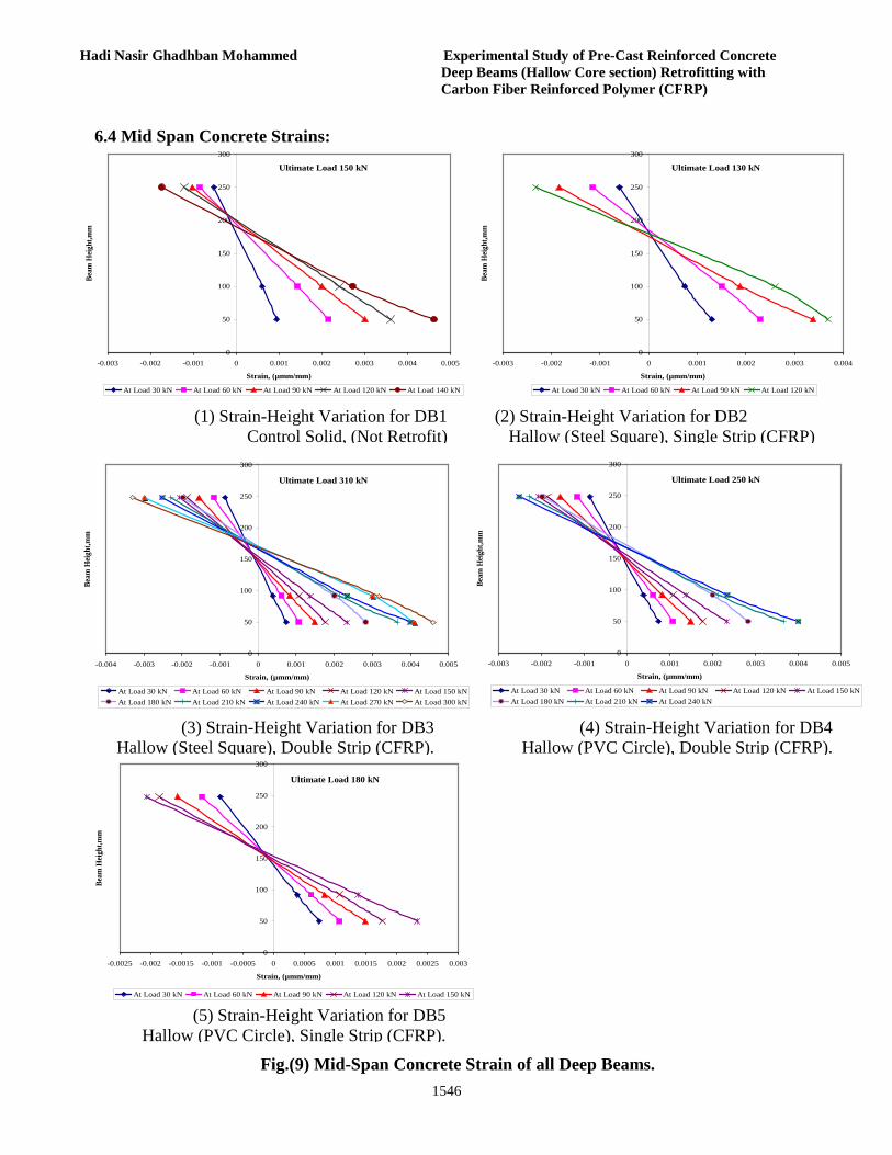
6.4 Mid Span Concrete Strains:
Ultimate Load 150 kN
0
50
100
150
200
250
300
-0.003 -0.002 -0.001 0 0.001 0.002 0.003 0.004 0.005
Strain, (µmm/mm)
Beam
Heig
ht,m
m
At Load 30 kN At Load 60 kN At Load 90 kN At Load 120 kN At Load 140 kN
Ultimate Load 130 kN
0
50
100
150
200
250
300
-0.003 -0.002 -0.001 0 0.001 0.002 0.003 0.004
Strain, (µmm/mm)
Beam
Heig
ht,m
m
At Load 30 kN At Load 60 kN At Load 90 kN At Load 120 kN
(1) Strain-Height Variation for DB1 Control Solid, (Not Retrofit)
(2) Strain-Height Variation for DB2 Hallow (Steel Square), Single Strip (CFRP)
(4) Strain-Height Variation for DB4 Hallow (PVC Circle), Double Strip (CFRP).
Ultimate Load 310 kN
0
50
100
150
200
250
300
-0.004 -0.003 -0.002 -0.001 0 0.001 0.002 0.003 0.004 0.005
Strain, (µmm/mm)
Beam
Heig
ht,m
m
At Load 30 kN At Load 60 kN At Load 90 kN At Load 120 kN At Load 150 kNAt Load 180 kN At Load 210 kN At Load 240 kN At Load 270 kN At Load 300 kN
Ultimate Load 250 kN
0
50
100
150
200
250
300
-0.003 -0.002 -0.001 0 0.001 0.002 0.003 0.004 0.005
Strain, (µmm/mm)
Beam
Heig
ht,m
m
At Load 30 kN At Load 60 kN At Load 90 kN At Load 120 kN At Load 150 kNAt Load 180 kN At Load 210 kN At Load 240 kN
(3) Strain-Height Variation for DB3 Hallow (Steel Square), Double Strip (CFRP). Ultimate Load 180 kN
0
50
100
150
200
250
300
-0.0025 -0.002 -0.0015 -0.001 -0.0005 0 0.0005 0.001 0.0015 0.002 0.0025 0.003
Strain, (µmm/mm)
Beam
Heig
ht,m
m
At Load 30 kN At Load 60 kN At Load 90 kN At Load 120 kN At Load 150 kN
(5) Strain-Height Variation for DB5 Hallow (PVC Circle), Single Strip (CFRP).
Fig.(9) Mid-Span Concrete Strain of all Deep Beams.
Journal of Engineering Volume 19 December 2013 Number 12
1547
Bearing Capacity of a Strip Model Footing on Loose Sand Reinforced With Pomegranate Sticks Mat
Huda Muwafak Jasim Ass.Lecturer in Building and Construction Engineering Department,
University of Technology,Baghdad, Iraq. [email protected]
ABSTRUCT A series of laboratory model tests has been carried out to investigate the using of pomegranate
sticks mat as reinforcement to increase the bearing capacity of footing on loose sand. The influence of depth and length of pomegranate sticks layer was examined. In the present research single layer of pomegranate sticks reinforcement was used to strengthen the loose sand stratum beneath the strip footing. The dimensions of the used foundation were 4*20 cm. The reinforcement layer has been embedded at depth 2, 4 and 8 cm under surcharge stresses . Reinforcing layer with length of 8 and 16 cm were used. The final model test results indicated that the inclusion of pomegranate sticks reinforcement is very effective in improvement the loading capacity of loose sand. The optimal benefit in bearing capacity value was realized as the (D/B) ratio (embedded depth to footing width) equal to 0.5.The bearing capacity of a reinforced soil with single layer of pomegranate sticks at (D/B) ratio of o.5 increased by about 4 times (corresponding to S/B =10%) than that for the unreinforced case and continuous in increasing beyond that with no failure. The improvement in bearing capacity decreased with increasing depth of embedment of reinforcement layer until reach to a specified point in which the bearing capacity of a reinforced soil approximately identical with the case of no reinforcement. Also it was found that increase the length of pomegranate sticks layer has no beneficial effect on the improved the bearing capacity of loose sand.
KEYWORDS: pomegranate sticks; sand; bearing capacity; reinforcement; strip.
قابلية تحمل موديل االساس الشريطي على التربة الرملية الضعيفة المسلحة باستخدام حصيرة أعواد الرمان
الجامعة التكنولوجية -في قسم هندسة البناء واالنشاءات .م.م -هدى موفق جاسم الخالصة
يهدف البحث الى استخدام بعض النباتات المحلية المتوفرة كمواد لتسليح الترب الرملية الضعيفة من خالل اجراء سلسلة من الفحوصات المختبرية .تم في هذه الدراسة استخدام اعواد الرمان لتسليح التربة الرملية و دراسة اختالف قابلية تحمل التربة الرملية
كذلك تم دراسة اختالف ،حصيرة المصنوعة من اعواد الرمان على اعماق مختلفة خالل موديل التربة الرمليةمن خالل وضع العلى قابلية تحميل التربة الرملية.طبقة تسليح مفردة تم استخدامها في تسليح التربة الرملية خالل هذه الدراسة طول الحصيرة
تحت تأثير االجهادات المسلطة .طول cm 8و4و2قة التسليح على عمق وضعت طب cm.20*4وكانت ابعاد االساس المستخدم النتائج المستحصلة اشرت بنجاح حصيرة سيقان الرمان في زيادة قابلية تحمل التربة cm. 16و 8طبقة التسليح المستخدمة كانت
وصلت الزيادة في قابلية تحمل cm 2الرملية وتقليل الهبوط الناتج من تسليط االحمال حيث عند وضع طبقة التسليح على عمق حالة عدم مع%) مقارنة 10تساوي (S/B ) التربة الرملية اربعة اضعاف (عندما كانت نسبة هبوط التربة الى عرض االساس
ان كذلك وجد واستخدام التسليح واستمرت التربة بعد هذه النسبة في تحمل المزيد من االحمال المسلطة عليها بدون حدوث فشل قابلية تحمل التربة تبدأ بالنقصان كلما زاد عمق طبقة التسليح تحت االساس وان الزيادة في طول طبقة التسليح ليس له اي تاثير على
زيادة قابلية تحمل التربة وبذلك تعتبر طريقة تسليح ناجحة ومقبولة. ،رمل،قابلية التحمل،تسليح،شريطي.الكلمات الرئيسية:اعواد الرمان

Huda Muwafak Jasim Bearing Capacity of a Strip Model Footing on Loose Sand Reinforced With Pomegranate Sticks Mat
1548
INTRODUCTION Plant roots stabilize soils through reinforcement
of soil in nature against erosion and failure of deep slopes. Presently reinforcement is an effective and reliable technique for increasing strength and stability of soils (Hataf and Rahimi,2005).
Soil can often be regarded as a combination of four basic types: gravel, sand, clay, and silt. It generally has low tensile and shear strength and its characteristics may depend strongly on the environmental conditions (e.g. dry versus wet). On the other hand, reinforcement consists of incorporating certain materials with some desired properties within other material which lack those properties. Therefore, soil reinforcement is defined as a technique to improve the engineering characteristics of soil in order to develop the parameters such as shear strength, compressibility, density; and hydraulic conductivity (Hejazi et.al.,2012).The roots of reinforced soil go back as far as biblical times and therefore it cannot be considered as a modern technique (Pedly, 1990).
Dikes constructed from earth and tree branches, have been used in China for at least 1000 years. In England wooden pegs, bamboo and wire mesh have been used for erosion and land slide control (Tilahun Tadess, 2006 ).
Until few years ago only natural materials were available : soil ,rocks ,wood, sand asphalt ,iron .Even concrete and steel are just mixtures or alloys of natural materials. In this long tradition the problem has always been that the natural materials used as inclusions have usually a limited durability and a very large and uncontrollable variability in their technical characteristics (TENAX, 2000).
The earliest use of reinforced soil was to build walls such as the ziggurats in lraq and the Great Wall of China. The ziggurat was reinforced with woven mats of reeds laid horizontally and with plaited ropes of the same material embedded in layers of sand and gravel while the Great Wall of China has tamarisk branches as reinforcement
embedded in a mixture of clay and gravel. Agar-Quf or the ziggurat of Dur-Kurigatzu in lraq and the Great Wall of China are reinforced soil Structures that were built thousands of years ago and still exist today.
The concept of reinforced earth was introduced in the 1960s by Henri Vidal in France. The structures were composed of flat reinforcing metal strips embedded in the soil. In 1970s the use of steel mesh or grid as reinforcement was introduced. The strength of a reinforced soil mass depends on the reinforcement strength , the reinforcement spacing , and the soil strength.
Initially, the applied load is carried by the soil until the soil starts to fail causing it to slide against the reinforcement. As slippage occurs between the soil and the reinforcement, friction is developed causing the reinforcement to stretch and mobilizing its strength. Reinforcement spaced too far apart leads to failure of the soil as if it were not reinforced at all. Thus, it is necessary to activate the reinforcement strength for the structure to be effective (David J.Elton, 2005).
The types of reinforcement materials, classified as either inextensible or extensible, have been used to reinforce earth. Zornberg defined inextensible reinforcement as a material that deforms considerably less than the surrounding soil at failure and extensible reinforcement as a material that deforms as much as the surrounding soil (Federal highway,2011).The beneficial effects of soil reinforcement drive from the soil’s increased tensile strength and the shear resistance developed from the friction at the soil-reinforcement interfaces (Fathi M.Abdrabbo et al., 2004).
LABORATORY MODEL TESTS
The model foundation used for this study had a width of 4 cm and a length of 20 cm. It was made out of a mild steel plate with a thickness of 1 cm. Bearing capacity tests are conducted in a box of dimension 50 cm(length)*30 cm(width)* 30 cm(depth).For all tests, the average unit weight and the relative density of sand are kept at 15.5
Journal of Engineering Volume 19 December 2013 Number 12
1549
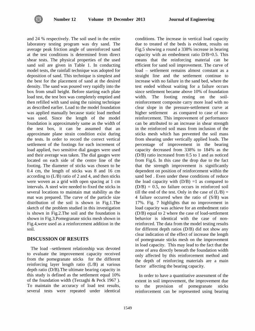
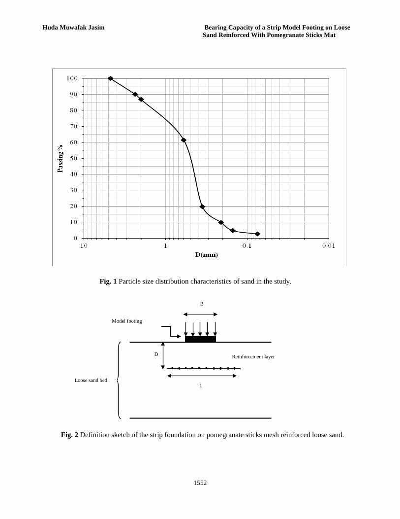
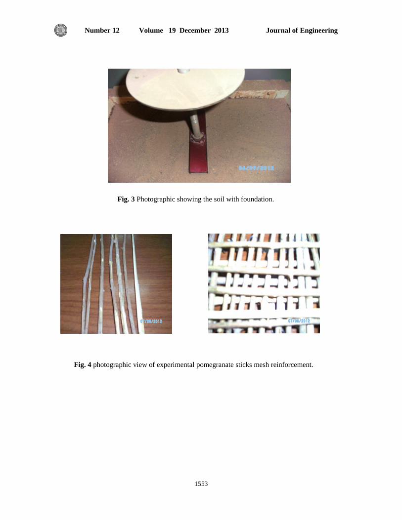
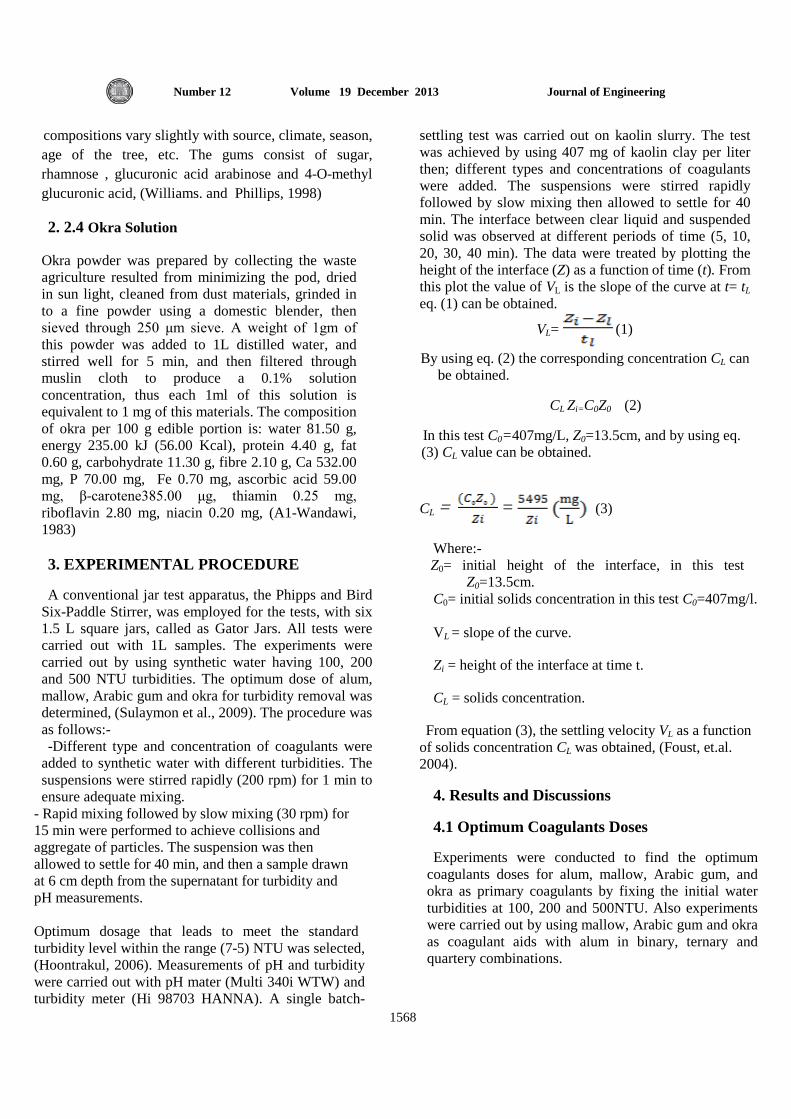
and 24 % respectively. The soil used in the entire laboratory testing program was dry sand. The average peak friction angle of unreinforced sand at the test conditions is determined from direct shear tests. The physical properties of the used sand soil are given in Table 1. In conducting model tests, the rainfall technique was adopted for deposition of sand. This technique is simplest and the best for the placement of sand at the desired density. The sand was poured very rapidly into the box from small height. Before starting each plate load test, the test box was completely emptied and then refilled with sand using the raining technique as described earlier. Load to the model foundation was applied manually because static load method was used. Since the length of the model foundation is approximately same as the width of the test box, it can be assumed that an approximate plane strain condition exist during the tests. In order to record the correct vertical settlement of the footings for each increment of load applied, two sensitive dial gauges were used and their average was taken. The dial gauges were located on each side of the centre line of the footing. The diameter of sticks was chosen to be 0.4 cm, the length of sticks was 8 and 16 cm according to (L/B) ratio of 2 and 4, and then sticks were woven as a grid with open spacing at 1 cm intervals. A steel wire needed to fixed the sticks in several locations to maintain mat stability as the mat was prepared. The curve of the particle size distribution of the soil is shown in Fig.1.The sketch of the problem studied in this investigation is shown in Fig.2.The soil and the foundation is shown in Fig.3.Pomegranate sticks mesh shown in Fig.4,were used as a reinforcement addition in the soil.
DISCUSSION OF RESUITS
The load –settlement relationship was devoted to evaluate the improvement capacity received from the pomegranate sticks for the different reinforcing layer length ratio (L/B) at various depth ratio (D/B).The ultimate bearing capacity in this study is defined as the settlement equal 10% of the foundation width (Terzaghi & Peck 1967 ). To maintain the accuracy of load test results, several tests were repeated under identical
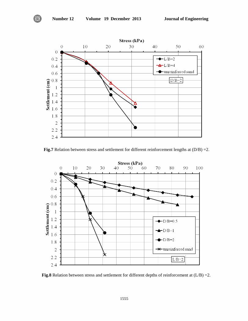
conditions. The increase in vertical load capacity due to treated of the beds is evident, results on Fig.5 showing a round a 338% increase in bearing capacity with an embedment ratio D/B=0.5. This means that the reinforcing material can be efficient for sand soil improvement. The curve of load – settlement remains almost constant as a straight line and the settlement continue to increase with no failure in the sand bed, where the test ended without waiting for a failure occurs since settlement became above 10% of foundation width. The footing resting on the soil-reinforcement composite carry more load with no clear slope in the pressure-settlement curve at higher settlement as compared to case of non-reinforcement. This improvement of performance can be attributed to an increase in shear strength in the reinforced soil mass from inclusion of the sticks mesh which has prevented the soil mass from shearing under vertically applied loads. The percentage of improvement in the bearing capacity decreased from 338% to 184% as the (D/B) ratio increased from 0.5 to 1 and as noticed from Fig.6. In this case the drop due to the fact that the strength improvement is significantly dependent on position of reinforcement within the sand bed . Even under these conditions of reduce the load capacity with (D/B) =1 as compared to (D/B) = 0.5, no failure occurs in reinforced soil till the end of the test. Only in the case of (L/B) = 4 failure occurred when the ratio of (S/B) was 17%. Fig. 7 highlights that no improvement in load capacity was achieve for an embedment ratio (D/B) equal to 2 where the case of load-settlement behavior is identical with the case of non-reinforced. The data from the model testing results for different depth ratios (D/B) did not show any clear indication of the effect of increase the length of pomegranate sticks mesh on the improvement in load capacity. This may lead to the fact that the zone of area directly beneath the foundation width only affected by this reinforcement method and the depth of reinforcing materials are a main factor affecting the bearing capacity.
In order to have a quantitative assessment of the extent in soil improvement, the improvement due to the provision of pomegranate sticks reinforcement can be represented using bearing

Huda Muwafak Jasim Bearing Capacity of a Strip Model Footing on Loose Sand Reinforced With Pomegranate Sticks Mat
1550
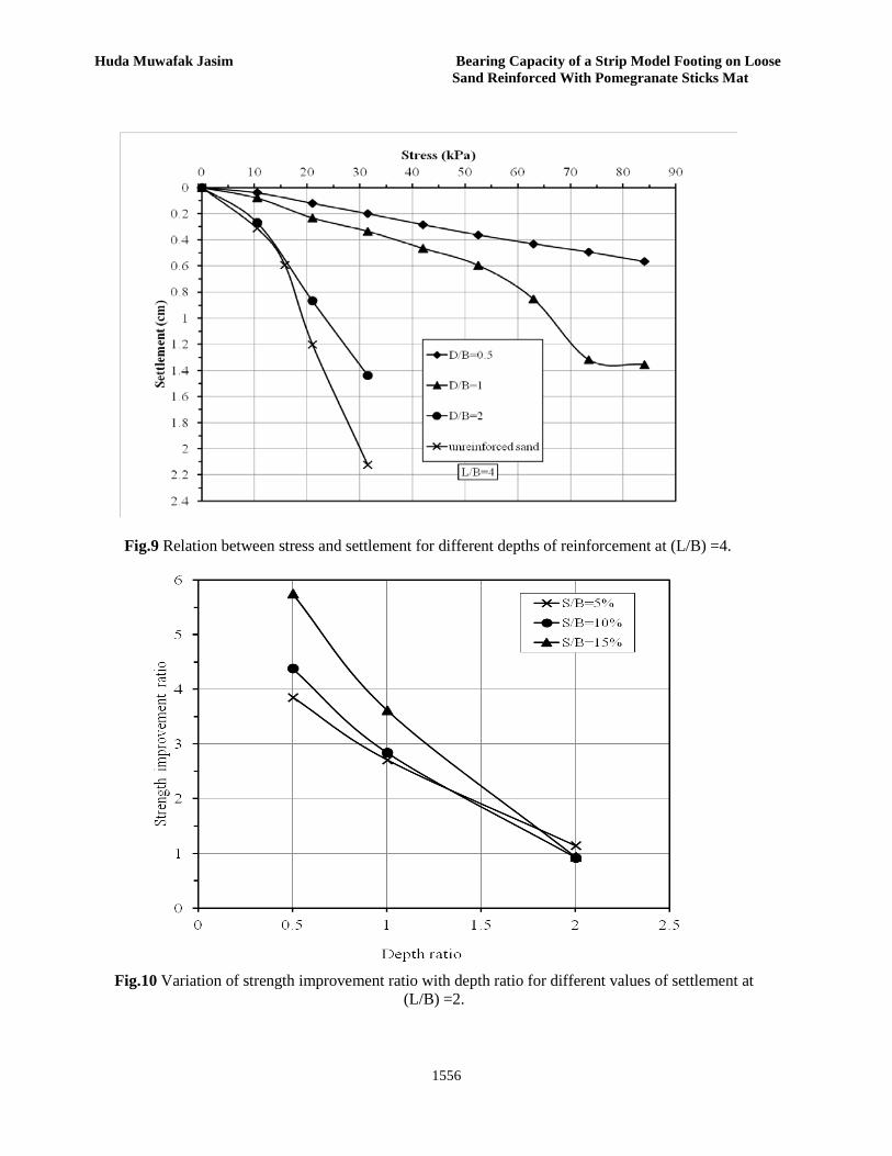
capacity ratio which is defined as the ratio between the ultimate loads attained from loading test on reinforced sand to that of the unreinforced sand at the same settlement. It is necessary to illustration the improvement in bearing capacity at different settlement levels hence, the pressures corresponding to settlement (settlement/width of plate*100) of 5, 10 and 15 have been compared (Table2) and the corresponding values of strength improvement ratio are presented in Fig.10.Can be seen from Fig.10 that the bearing capacity ratio generally shows an increase with increase in footing settlement .This is because in loose sand, large deformation of the footing are required to mobilize the beneficial effects of the reinforcement. This is due to increase of the frictional resistance at the soil-reinforcement interface as greater mobilization of reinforcement take place as the settlement increase.
CONCLUSIONS
The following conclusions may be drawn from this study regarding the effect of pomegranate sticks reinforcement on the pressure versus settlement behavior of a strip model footing founded a loose sand:
1) The results prove the usefulness in using pomegranate sticks in geotechnical aspects.
2) The bearing capacity of a loose sand reinforced with a pomegranate sticks mat increases by about 4 times at depth 2 cm (for S/B=10%) as compared with the case of no improvement .
3) At a (D/B) ratio of 0.5 and 1, no failure occurs in the soil ,where the settlement exceeds a high percentage without failure.
4) A single reinforcement layer of pomegranate sticks mat increases the bearing capacity, depending on the depth ratio (D/B).
5) No beneficial of increasing the (D/B) ratio to 2 to improve the load capacity of sand soil.
6) The increase in ultimate bearing capacity of sand bed due to increase the length of pomegranate sticks mesh becomes useless.
REFERENCES
David J.Elton , and Maria Aries Barrato Patawaran,(2005),” Mechanically Stabilized Earth (MSE) Reinforceement Tensile Strenght From Tests of Geotextile Reinforced Soil”, Highway Research Center Frazier parker,Jr.,Director.
Faith Abdrabbo, Member ,ASCE, Khaled E. Gaaver, and Amr Z. Elwakil,(2004),”Behavior of Square Footings on Single Reinforced Soil”, ASCE, GeoSupport 2004: pp. 1015-1026, doi: 10.1061/40713(2004)83.
Federal Highway Administration,(2011),” Geosythetic Reinforced Soil Integrated Bridge System Synthesis”, Report, Publication Number: FHWA-HRT-11-027, Federal Highway Administration, and U.S. Department of Iansportation.
Hejazi S., Sheikhzadeh M.,Abtahi S., and Zadhoush A., (2012),”Asimple Review of Soil Reinforcement By Using Natural and Synthetic Fibers”,Construction and Building Materials,Vol.30, Pages 100-116.
Hataf N., and Rahimi M.M., (2005),” Experimental Investigation of Bearing Capacity of Sand Reinforced With Randomly Distributed Tire Shreds”, Construction and Building Materials, Vol.20, Issue 10, Page 910-916.
J.G.Zornberg,(2002),”Peak Versus Residual Shear Strength in Geosynthetic Reinforced Soil Design”,Geosynthetics International,Vol.9,No.4.
Martin john pedly,(1990),”The Performance of Soil Reinforcement in Bending and Shear”,Ph.D.Thesis, University of Oxford.
Tenax SPA,”Reinforced Soil Slopes and Walls”,http://www.tenax.net.
Tilahun Tadesse,(2006),”Reinforced Earth Retaining Wall Design Using Reinforcement Steel With Gabion Facing “,M.Sc.Thesis,University of Addis Ababa.

Journal of Engineering Volume 19 December 2013 Number 12
1551
Terzaghi,K. and Peck,R.B ,(1967)," Soil Mechanic in Engineering Practice", 2nd Edition ,Wiley , NewYork.
Specific gravity 2.66
Maximum dry unit weight (kN/m³) 19.2
Minimum dry unit weight (kN/m³) 14.6
Dry unit weight (kN/m³) 15.5
Relative density of sand (Dr %) 24
Angle of internal friction(degree) 29
Classification SP
Pressure (kPa) corresponding to
(D/B) (S/B) 5% (S/B) 10% (S/B) 15%
(L/B)=2 (L/B)=4 (L/B)=2 (L/B)=4 (L/B)=2 (L/B)=4
0.5 27 31 57 57 92 92
1 19 19 37 35 58 53
2 8 8 12 13 15 16.5
Unreinforced 7 7 13 13 16 16
Table 1 Properties of sand used in the study.
Table 2 Footing pressure corresponding to various values of settlement (S/B) for the different test series.
Huda Muwafak Jasim Bearing Capacity of a Strip Model Footing on Loose Sand Reinforced With Pomegranate Sticks Mat
1552
D
B
Reinforcement layer
Loose sand bed
Model footing
L
Fig. 1 Particle size distribution characteristics of sand in the study.
Fig. 2 Definition sketch of the strip foundation on pomegranate sticks mesh reinforced loose sand.
Journal of Engineering Volume 19 December 2013 Number 12
1553
Fig. 3 Photographic showing the soil with foundation.
Fig. 4 photographic view of experimental pomegranate sticks mesh reinforcement.

Huda Muwafak Jasim Bearing Capacity of a Strip Model Footing on Loose Sand Reinforced With Pomegranate Sticks Mat
1554
Fig.5 Relation between stress and settlement for different reinforcement lengths at (D/B) =0.5.
Fig.6 Relation between stress and settlement for different reinforcement lengths at (D/B) =1.
Journal of Engineering Volume 19 December 2013 Number 12
1555
Fig.7 Relation between stress and settlement for different reinforcement lengths at (D/B) =2.
Fig.8 Relation between stress and settlement for different depths of reinforcement at (L/B) =2.
Huda Muwafak Jasim Bearing Capacity of a Strip Model Footing on Loose Sand Reinforced With Pomegranate Sticks Mat
1556
Fig.9 Relation between stress and settlement for different depths of reinforcement at (L/B) =4.
Fig.10 Variation of strength improvement ratio with depth ratio for different values of settlement at (L/B) =2.

Journal of Engineering Volume 19 December 2013 Number 12
1557
Forward Osmosis Process for the Treatment of Wastewater from Textile Industries
Dr. Hasan F. Makki, Dr. Majid I. Abdul Wahab and Rana Raheem Said Chemical Engineering Department – College of Engineering – University of Baghdad – Iraq.
ABSTRACT
This paper was aimed to study the efficiency of forward osmosis (FO) process as a new application for the treatment of wastewater from textile effluent and the factors affecting the performance of forward osmosis process. The draw solutions used were magnesium chloride (MgCl2), and aluminum sulphate (Al2 ( SO4)3 .18 H2O), and the feed solutions used were reactive red, and disperse blue dyes. Experimental work were includes operating the forward osmosis process using thin film composite (TFC) membrane as flat sheet for different draw solutions and feed solutions. The operating parameters studied were : draw solutions concentration (10 – 90 g/l), feed solutions concentration (5 – 30 mg/l), draw solutions flow rate (10 – 50 l/hr), feed solutions flow rate (20-60 l/hr), constant pressure and temperature were maintained at 0.5 bar and 30ºC respectively. And includes operating the forward osmosis process using cellulose triacetate (CTA) membrane as flat sheet for different draw solutions and feed solutions. The operating parameters studied were : draw solutions concentration (10 – 90 g/l), and feed solutions concentration (5 – 30 mg/l), constant temperature at 30ºC. It was found that water flux increases with increasing draw solution concentration, and feed solution flow rate and decreases with increasing draw solution flow rate and feed solution concentration for TFC and CTA. It was found MgCl2 given water flux larger than Alum. And also found that reactive red given water flux larger than disperse blue. The experiments also show that CTA membrane gives higher water flux than TFC membrane for forward osmosis operation. The increase in water flux for CTA is about 12.85% than TFC. KEYWORDS: Forward Osmosis; Textile Wastewater; Membranes.
من الصناعات النسيجية مخلفات المياهعملية التناضح االمامية لمعالجة
رنا رحيم سيد ،ماجد ابراهيم عبدالوهابد.حسن فرهود مكي، د. العراق -جامعة بغداد -كلية الهندسة –قسم الهندسة الكيمياوية
الخالصة
االمامي كتطبيق جديد لمعالجة الفض�الت الخارج�ة م�ن الص�ناعات النس�يجية والعوام�ل الت�ي يهدف هذا البحث الى دراسة كفاءة عملية التناضح تؤثر على اداء عملية التناضح االمامي .
الزرق محاليل السحب المستخدمة هي : كلوريد المغنيسيوم و كبريتات االلمنيوم المائي�ة و محالي�ل اللق�يم المس�تعملة ه�ي : االحم�ر المتفاع�ل و ا ر . المنتش
) على شكل صفيحة مستوية لمحاليل سحب مختلفة و محاليل TFCالعمل التجريبي يتضمن تشغيل عملية التناضح االمامي باستخدام اغشية ( مع�دل ملغم / لتر ) ،30-5غرام / لتر )، تركيز محاليل اللقيم (90-10لقيم مختلفة. العوامل التشغيلية التي تم دراستها : تركيز محاليل السحب (
لت��ر / س�اعة). الض�غط و درج��ة 60-20لت�ر / س��اعة ) ، مع�دل الجري�ان الحجم��ي لمحالي�ل اللق�يم ( 50-10الجري�ان الحجم�ي لمحالي��ل الس�حب ( عل�ى ش�كل CTAلك يتضمن تشغيل الوحدة التناضحية بأس�تخدام اغش�ية م�ن ن�وع ذعلى التوالي . وك م o 30بار و 0.5الحرارة ثابتين عند
ملغ�م / 30-5غ�رام / لت�ر ) ، و تركي�ز محالي�ل اللق�يم ( 90-10ستوية . العوامل التشغيلية التي تم دراستها : تركيز محالي�ل الس�حب ( صفيحة م .م 30oلتر )عند درجة حرارة ثابتة
بزيادة معدل الجري�ان الحجم�ي لقد وجد بأن معدل تدفق الماء يزداد بزيادة تركيز محلول السحب و معدل الجريان الحجمي لمحلول اللقيم ويقل ) .(CTA) و(TFCلمحلول السحب و تركيز محلول اللقيم لكال الغشائين

Hasan F. Makki Forward Osmosis Process for the Treatment of Majid I. Abdul Wahab Wastewater from Textile Industries Rana Raheem Said
1558
ت�دفق لقد وجد بان كلوريد المغنيسيوم يعطي معدل تدفق ماء اعلى من كبريتات االلمنيوم المائية . وايضا وجد بان االحمر المتفاعل يعطي مع�دل
ف�ي عملي�ات التناض�ح TFCطي معدل تدفق ماء اعلى من اغشية عت CTAت التجارب ايضا ان اغشية ماء اعلى من االزرق المنتشر. اظهر .TFC من اغشية% 12,85تقريبا CTAغشية ال معدل تدفق ماءان الزيادة في االمامي.
INTRODUCTION
The textile industry can be considered as one of the greatest consumers of water, due to high consumption necessary to adequately treat large quantities of effluents before their discharge to the environment. Some of these effluents are colored despite containing only small amounts of dyes. These dyes are toxic and, in most cases, are not biodegradable or their biodegradation is difficult and they resist well physico-chemical treatment method (Ulsonetal.,2009). Presence of very small amounts of dyes in water( less than 1 ppm for some dyes ) is highly visible and undesirable therefore it is necessary to eliminate dyes from waste water before it is discharge (Maryam et al., 2008). Color is the first contaminant to be recognized in the wastewater and has to be removed before discharging into water bodies or on land (Abbas, 2005). Complex aromatic structures of most dyes make it very difficult for conventional treatment methods such as activated sludge, ozonation and electrochemical techniques to be effective in achieving good color removal. However, excellent results were obtained using membrane processes which are proven to be very successful in removing the undesired color (Mohamed et al., 2007). Membrane separation processes has the ability to clarify, concentrate and most importantly, to separate dye continuously from effluent (Adul Latif et al., 2002). Membrane separation has gained increasing popularity in water, wastewater and many other industrial applications(Yuan et al., 2010). The separation of water from aqueous
solution usin polymeric membranes has been studied intensely for the past half century. Over this time, pressure – driven membrane separations, namely microfiltration ( MF ) , ultrafiltration ( UF ), nanofiltration ( NF ), and reverse osmoses (RO) have become more popular as a viable separation technique for removing undesired solutes from a solution. These pressure – driven membrane process have been employed heavily in the field of water treatment using forward osmosis ( FO ) as an alternative to pressure – driven membrane process has been gaining some popularity in the last few years (Jeffry et al ., 2006). In FO the force for mass
transport is the difference in osmotic pressure between the the feed solution and a draw solution, water diffuses from the feed solution of higher chemical potential (low osmotic pressure ) to a draw solution of lower chemical potential (higher osmotic pressure). As water diffuse through the membrane the feed solution becomes concentration and the draw solution is diluted (Riziero et al., 2009 ). . The main objective of this work is to study the efficiency of forward osmosis (FO) process as a new application for the treatment of water from textile effluent. In this search using Alum and MgCl2 as draw solution to extract water from textile effluent across a semi – permeable membrane ,and using reactive red and disperse blue dyes as feed solution (which are mainly used in Al-Hilla Textile Company ).
EXPERIMENTAL
• Draw Solution
Deionized water of ( 8 – 20 µs/cm ) conductivity was used for preparing aluminum sulphate (Al2 ( SO4)3 .18 H2O), magnesium chloride (MgCl2 ) solutions which were used as draw solution. Table 1 shows draw solutions concentration and their conductivities at 30 ºC temperature and chemical analysis of the draw
solutions.
• Feed Solution
Deionzed water of 8 – 20 µs / cm conductivity, was used for preparing reactive red and disperse blue. These dyes represented the most commonly used in Al-Hilla. Textile
Company as listed in Table 2.
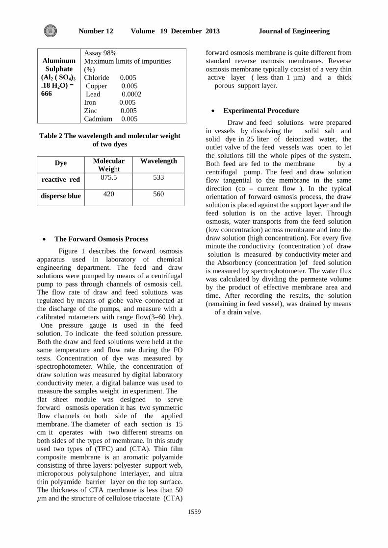
Table1Chemical Specification of Draw solution
Substance Properties
Assay 98% Maximum limits of impurities (%) Sulfate 0.002 Copper 0.002 Lead 0.005 Iron 0.0005 Zinc 0.0005 Cadmium 0.005
Magnesium Chloride
MgCl2= 95
Journal of Engineering Volume 19 December 2013 Number 12
1559
Assay 98% Maximum limits of impurities (%) Chloride 0.005 Copper 0.005 Lead 0.0002 Iron 0.005 Zinc 0.005 Cadmium 0.005
Aluminum Sulphate
(Al2 ( SO4)3 .18 H2O) = 666
Table 2 The wavelength and molecular weight
of two dyes
Dye Molecular Weight
Wavelength
reactive red 875.5 533
disperse blue 420 560
• The Forward Osmosis Process
Figure 1 describes the forward osmosis apparatus used in laboratory of chemical engineering department. The feed and draw solutions were pumped by means of a centrifugal pump to pass through channels of osmosis cell. The flow rate of draw and feed solutions was regulated by means of globe valve connected at the discharge of the pumps, and measure with a calibrated rotameters with range flow(3–60 l/hr). One pressure gauge is used in the feed solution. To indicate the feed solution pressure. Both the draw and feed solutions were held at the same temperature and flow rate during the FO tests. Concentration of dye was measured by spectrophotometer. While, the concentration of draw solution was measured by digital laboratory conductivity meter, a digital balance was used to measure the samples weight in experiment. The flat sheet module was designed to serve forward osmosis operation it has two symmetric flow channels on both side of the applied membrane. The diameter of each section is 15 cm it operates with two different streams on both sides of the types of membrane. In this study used two types of (TFC) and (CTA). Thin film composite membrane is an aromatic polyamide consisting of three layers: polyester support web, microporous polysulphone interlayer, and ultra thin polyamide barrier layer on the top surface. The thickness of CTA membrane is less than 50 µm and the structure of cellulose triacetate (CTA)
forward osmosis membrane is quite different from standard reverse osmosis membranes. Reverse osmosis membrane typically consist of a very thin active layer ( less than 1 µm) and a thick
porous support layer.
• Experimental Procedure
Draw and feed solutions were prepared in vessels by dissolving the solid salt and solid dye in 25 liter of deionized water, the outlet valve of the feed vessels was open to let the solutions fill the whole pipes of the system. Both feed are fed to the membrane by a centrifugal pump. The feed and draw solution flow tangential to the membrane in the same direction (co – current flow ). In the typical orientation of forward osmosis process, the draw solution is placed against the support layer and the feed solution is on the active layer. Through osmosis, water transports from the feed solution (low concentration) across membrane and into the draw solution (high concentration). For every five minute the conductivity (concentration ) of draw solution is measured by conductivity meter and the Absorbency (concentration )of feed solution is measured by spectrophotometer. The water flux was calculated by dividing the permeate volume by the product of effective membrane area and time. After recording the results, the solution (remaining in feed vessel), was drained by means
of a drain valve.

Hasan F. Makki Forward Osmosis Process for the Treatment of Majid I. Abdul Wahab Wastewater from Textile Industries Rana Raheem Said
1560
Dye Solution FeedDraw solution Feed
Osmosis Cell
Rotameters
Solution Product
Thermometer
Fig. 1 Schematic Diagram of Forward Osmosis Process
RESULTS AND DISCUSSION
Effect of Thin Film Composite Membrane
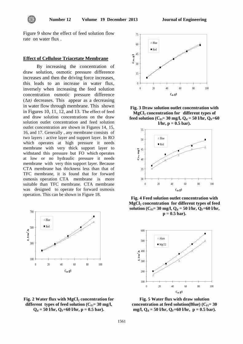
The water flux calculated by dividing the volume of pure water which transfers from feed to draw solution on time and active area of membrane. The water flux increases with increasing draw solution concentration because the driving force (osmotic pressure of draw solution – osmotic pressure of dye ) increased. An increase as demonstrated in Figure 2 for Magnesium chloride (MgCl2) as draw solution at two types of feed solution. The solution of dye loses quantities of pure water and this leads to increased concentration of dye. The same quantities of pure water transferred across the membrane to the draw solution, as a result, decrease the concentration of draw solution. Thus, increases or decreases in concentrations of draw solution and dye are linked to each other. The effect of draw solution concentration on draw solution outlet concentration (Cdo) is shown in Figure3. Figure 4 show the effect of draw solution concentration on feed solution outlet concentration(CFo) at two types of feed solution. Figure 5 show the effect of the types of draw solution on water flux , MgCl2 has a high water flux because it has high osmotic pressure (driving force) than Alum. Increasing of osmotic pressure
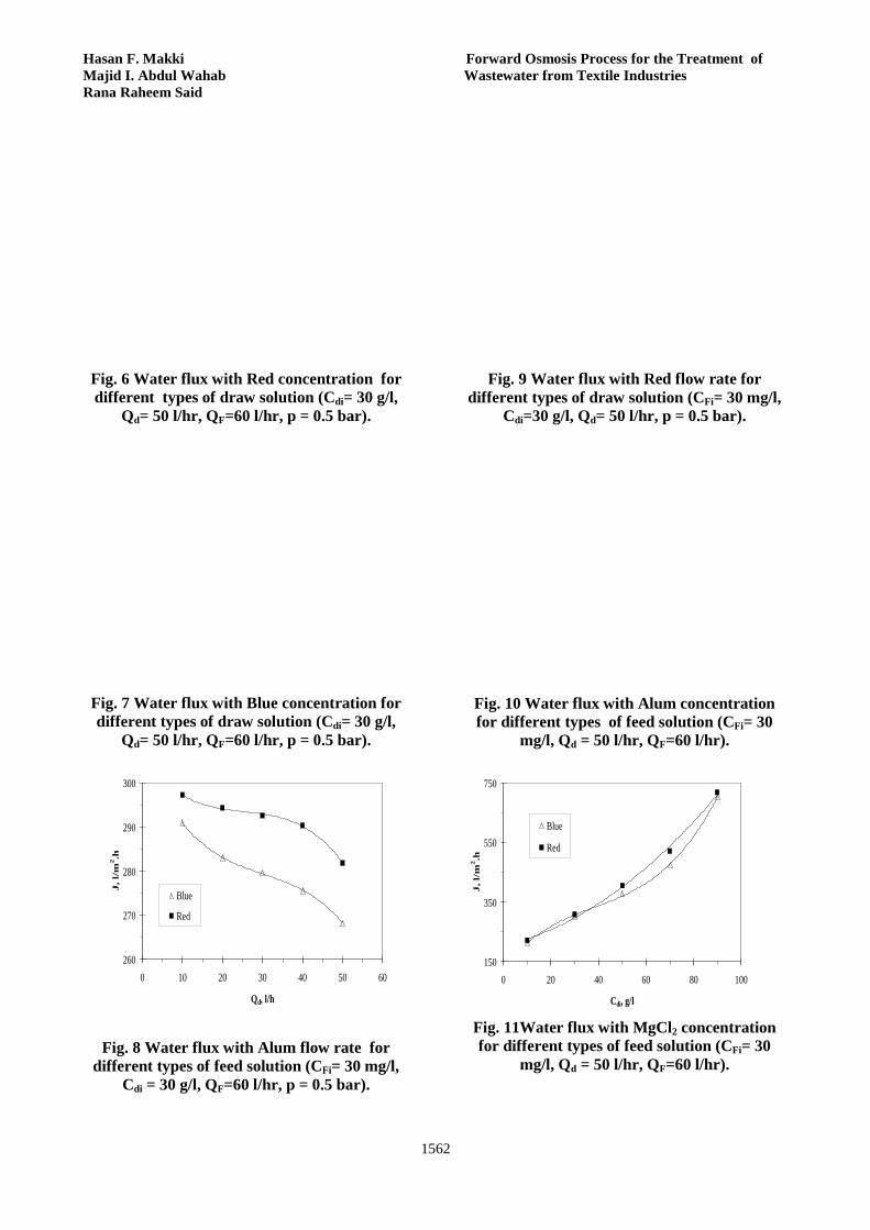
of draw solution will increase the driving force (Δπ) for water flux. At the same concentration of draw solutions, osmotic pressure depends on the molecular weight of solute, and number of dissociates. The increase in water flux resulted from Red is larger than Blue because it has low osmotic pressure (driving force) than Blue. By increasing feed solution concentration (CFi) driving force decreases. This appears as a decrease of water flux through the membrane. The water flux decreasing with increasing feed solution concentration because the driving force (osmotic pressure of draw solution – osmotic pressure of dye ) decreased. This is shown in Figures 6, and 7 for Red and Blue as feed solution at two types of draw solution. Increasing the draw solution flow rate (Qd) prevents the concentration buildup in the solution at the vicinity of the membrane surface (support layer ), and resulting in decreasing the driving force. Thus , water flux decreased with increasing the flow rate .This is shown in Figure 8. Increasing the feed solution flow rate prevents the concentration buildup in the solution at the vicinity of the membrane surface (Active layer ), leading to increase a driving force(Δπ).This behavior contradicts the case of increasing the draw solution flow rate.
Journal of Engineering Volume 19 December 2013 Number 12
1561
Figure 9 show the effect of feed solution flow rate on water flux .
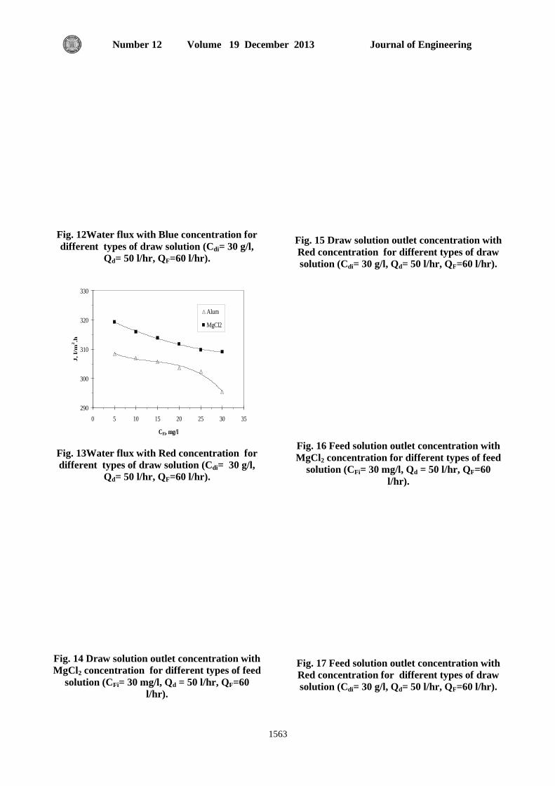
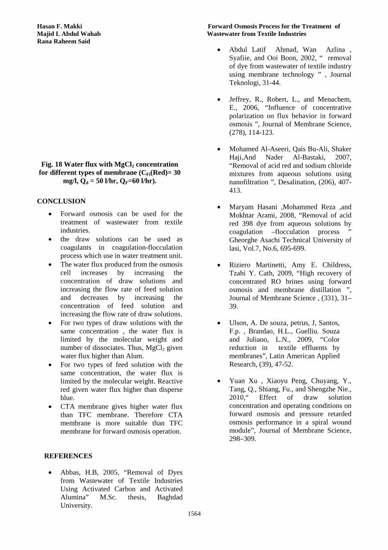
Effect of Cellulose Triacetate Membrane By increasing the concentration of draw solution, osmotic pressure difference increases and then the driving force increases, this leads to an increase in water flux, inversely when increasing the feed solution concentration osmotic pressure difference (Δπ) decreases. This appear as a decreasing in water flow through membrane. This shown in Figures 10, 11, 12, and 13. The effect of feed and draw solution concentrations on the draw solution outlet concentration and feed solution outlet concentration are shown in Figures 14, 15, 16, and 17. Generally , any membrane consists of two layers : active layer and support layer. In RO which operates at high pressure it needs membrane with very thick support layer to withstand this pressure but FO which operates at low or no hydraulic pressure it needs membrane with very thin support layer. Because CTA membrane has thickness less than that of TFC membrane, it is found that for forward osmosis operation CTA membrane is more suitable than TFC membrane. CTA membrane was designed to operate for forward osmosis operation. This can be shown in Figure 18.
100
300
500
700
0 20 40 60 80 100
Cdi, g/l
J,
l/m
2.h
Blue
Red
0
15
30
45
60
75
0 20 40 60 80 100
Cdi, g/l
Cd
o, g
/l
Blue
Red
Fig. 3 Draw solution outlet concentration with
MgCl2 concentration for different types of feed solution (CFi= 30 mg/l, Qd = 50 l/hr, QF=60
l/hr, p = 0.5 bar).
30
35
40
45
50
55
0 20 40 60 80 100
Cdi, g/l
CF
o, m
g/l
Blue
Red
Fig. 4 Feed solution outlet concentration with
MgCl2 concentration for different types of feed solution (CFi= 30 mg/l, Qd = 50 l/hr, QF=60 l/hr,
p = 0.5 bar).
100
200
300
400
500
600
0 20 40 60 80 100
Cdi, g/l
J, l
/m2 .h
Alum
MgCl2
Fig. 2 Water flux with MgCl2 concentration for different types of feed solution (CFi= 30 mg/l,
Qd = 50 l/hr, QF=60 l/hr, p = 0.5 bar).
Fig. 5 Water flux with draw solution concentration at feed solution(Blue) (CFi= 30 mg/l, Qd = 50 l/hr, QF=60 l/hr, p = 0.5 bar).
Hasan F. Makki Forward Osmosis Process for the Treatment of Majid I. Abdul Wahab Wastewater from Textile Industries Rana Raheem Said
1562
Fig. 6 Water flux with Red concentration for different types of draw solution (Cdi= 30 g/l,
Qd= 50 l/hr, QF=60 l/hr, p = 0.5 bar).
Fig. 7 Water flux with Blue concentration for different types of draw solution (Cdi= 30 g/l,
Qd= 50 l/hr, QF=60 l/hr, p = 0.5 bar).
260
270
280
290
300
0 10 20 30 40 50 60
Qd, l/h
J, l/
m2.h
Blue
Red
Fig. 8 Water flux with Alum flow rate for different types of feed solution (CFi= 30 mg/l,
Cdi = 30 g/l, QF=60 l/hr, p = 0.5 bar).
Fig. 9 Water flux with Red flow rate for
different types of draw solution (CFi= 30 mg/l, Cdi=30 g/l, Qd= 50 l/hr, p = 0.5 bar).
Fig. 10 Water flux with Alum concentration for different types of feed solution (CFi= 30
mg/l, Qd = 50 l/hr, QF=60 l/hr).
150
350
550
750
0 20 40 60 80 100
Cdi, g/l
J, l
/m2 .h
Blue
Red
Fig. 11Water flux with MgCl2 concentration for different types of feed solution (CFi= 30
mg/l, Qd = 50 l/hr, QF=60 l/hr).
Journal of Engineering Volume 19 December 2013 Number 12
1563
Fig. 12Water flux with Blue concentration for different types of draw solution (Cdi= 30 g/l,
Qd= 50 l/hr, QF=60 l/hr).
290
300
310
320
330
0 5 10 15 20 25 30 35
CFi, mg/l
J, l
/m2 .h
Alum
MgCl2
Fig. 13Water flux with Red concentration for different types of draw solution (Cdi= 30 g/l,
Qd= 50 l/hr, QF=60 l/hr).
Fig. 14 Draw solution outlet concentration with MgCl2 concentration for different types of feed
solution (CFi= 30 mg/l, Qd = 50 l/hr, QF=60 l/hr).
Fig. 15 Draw solution outlet concentration with Red concentration for different types of draw solution (Cdi= 30 g/l, Qd= 50 l/hr, QF=60 l/hr).
Fig. 16 Feed solution outlet concentration with MgCl2 concentration for different types of feed
solution (CFi= 30 mg/l, Qd = 50 l/hr, QF=60 l/hr).
Fig. 17 Feed solution outlet concentration with Red concentration for different types of draw solution (Cdi= 30 g/l, Qd= 50 l/hr, QF=60 l/hr).
Hasan F. Makki Forward Osmosis Process for the Treatment of Majid I. Abdul Wahab Wastewater from Textile Industries Rana Raheem Said
1564
Fig. 18 Water flux with MgCl2 concentration
for different types of membrane (CFi(Red)= 30 mg/l, Qd = 50 l/hr, QF=60 l/hr).
CONCLUSION
• Forward osmosis can be used for the treatment of wastewater from textile industries.
• the draw solutions can be used as coagulants in coagulation-flocculation process which use in water treatment unit.
• The water flux produced from the osmosis cell increases by increasing the concentration of draw solutions and increasing the flow rate of feed solution and decreases by increasing the concentration of feed solution and increasing the flow rate of draw solutions.
• For two types of draw solutions with the same concentration , the water flux is limited by the molecular weight and number of dissociates. Thus, MgCl2 given water flux higher than Alum.
• For two types of feed solution with the same concentration, the water flux is limited by the molecular weight. Reactive red given water flux higher than disperse blue.
• CTA membrane gives higher water flux than TFC membrane. Therefore CTA membrane is more suitable than TFC membrane for forward osmosis operation.
REFERENCES
• Abbas, H.B, 2005, “Removal of Dyes from Wastewater of Textile Industries Using Activated Carbon and Activated Alumina” M.Sc. thesis, Baghdad University.
• Abdul Latif Ahmad, Wan Azlina , Syafiie, and Ooi Boon, 2002, “ removal of dye from wastewater of textile industry using membrane technology ” , Journal Teknologi, 31-44.
• Jeffrey, R., Robert, L., and Menachem, E., 2006, “Influence of concentrative polarization on flux behavior in forward osmosis ”, Journal of Membrane Science, (278), 114-123.
• Mohamed Al-Aseeri, Qais Bu-Ali, Shaker Haji,And Nader Al-Bastaki, 2007, “Removal of acid red and sodium chloride mixtures from aqueous solutions using nanofiltration ”, Desalination, (206), 407-413.
• Maryam Hasani ,Mohammed Reza ,and Mokhtar Arami, 2008, “Removal of acid red 398 dye from aqueous solutions by coagulation –flocculation process ” Gheorghe Asachi Technical University of lasi, Vol.7, No.6, 695-699.
• Riziero Martinetti, Amy E. Childress, Tzahi Y. Cath, 2009, “High recovery of concentrated RO brines using forward osmosis and membrane distillation ”, Journal of Membrane Science , (331), 31–39.
• Ulson, A. De souza, petrus, J, Santos, F.p. , Brandao, H.L., Guelliu. Souza and Juliano, L.N., 2009, “Color reduction in textile effluents by membranes”, Latin American Applied Research, (39), 47-52.
• Yuan Xu , Xiaoyu Peng, Chuyang, Y., Tang, Q., Shiang, Fu., and Shengzhe Nie., 2010,“ Effect of draw solution concentration and operating conditions on forward osmosis and pressure retarded osmosis performance in a spiral wound module”, Journal of Membrane Science, 298–309.

Journal of Engineering Volume 19 December 2013 Number 12
1565
NOMENCLATURE
Symbol Definition Units Cdi Draw solution
concentration g/l
Cdo Draw solution outlet concentration
g/l
CFi Feed solution concentration
mg/l
CFo Feed solution outlet concentration
mg/l
J Water flux l/m2.hr P Pressure bar Qd Draw solution flow rate l/hr QF Feed solution flow rate l/hr T Temperature 0C ABBREVIATIO Symbol Definition Alum Aluminume sulphate Blue Disperse blue CTA Cellulose triacetate FO Forward osmosis MF Microfiltration Red Reactive red RO Reverse osmosis TFC Thin film composite UF Ultrafiltration

Journal of Engineering Volume 19 December 2013 Number 12
1566
Removal of Water Turbidity by Different Coagulants Prof. Dr. Abbas H. Sulaymon Asst. Prof. Muna Y. Abdul-Ahad Roaa A.Mahmood University of Baghdad University of Baghdad University of Baghdad College of Engineering College of Engineering College of Engineering
Energy engineering department Environmental Engineering Department Environmental Engineering Department
[email protected] [email protected] [email protected]
ABSTRACT
During the last decade, there has been a concern about the relation between aluminum residuals in treated water and Alzheimer disease, and more interest has been considered on the development of natural coagulants. The present study aimed to investigate the efficiency of alum as a primary coagulant in conjunction with mallow, Arabic gum and okra as coagulant aids for the treatment of water samples containing synthetic turbidity of kaolin. Jar test experiments were carried out for initial raw water turbidities 100, 200 and 500 (NTU). The optimum doses of alum, mallow, Arabic gum and okra were 20, 2, 1 and 1 mg/L for100 NTU turbidity level, 35, 4, 2 and 3 mg/L , for 200NTU turbidity level and 50, 8, 10 and 8 mg/L for 500 NTU turbidity level, respectively. The optimum pH was 7 for alum, and 7.5 for mallow, Arabic gum and okra. The residual turbidity was 3.34 to 6.81 NTU by using alum as a primary coagulant with mallow, Arabic gum and okra, and pH values of the treated water by the natural coagulants were 6.1 to 7.01. The optimum dose of the natural coagulants in the present study has higher efficiency in removing high turbidity in comparison with low turbidity. Natural coagulant showed many advantages in coagulation/flocculation process. By using natural coagulants, considerable decreasing in Al2(SO4)3 consumption, and Increasing in the rate of sedimentation can be achieved.
KEY WORDS: Coagulant, jar test, flocculation, kaolin, turbidity.
مختلفة مخثرات باستعمال الماء عكوره إزالةرؤى الرزاق دعب محمود ;منى يوسف عبد األحد أ.معباس حميد سليمون؛ .د ا
الخالصة
ن هناك اهتمام حول العالقة بين بقايا االلمنيوم في الماء المعالج ومرض الخرف المبكر (الزهايمر)،ل�ذا ظه�ر اهتم�ام كبي�ر ف�ي تط�وير خالل العقد االخير،لقد كاعرب�ي ، الص�مغ الاستخدام المخثرات الطبيعية في عمليات معالجة الماء. الدراسة الحالية تهدف ال�ى تقي�يم كف�اءة ك�ل م�ن الش�ب ومخث�رات طبيعي�ة ه�ي الملوخي�ة
لم��اء و بمس�تويات عك��ورة لب باس�تعمال جه��از فح�ص الج�رة رومخلف�ات البامي�ة ف��ي معالج�ة عين�ات م��اء ت�م تحض�يرها باس��تعمال ط�ين الك�اؤلين.تم أج��راء التج�المس�توى العك�ورة ملغم/لت�ر 3و 2، 4، 35وح�دة نفل�ومتر ،100ملغم/لت�ر لمس�توى العك�ورة 1و 1، 2، 20وحدة نفلومتر. الجرع المثلى كان�ت 500و200,100
7المثل�ى كان�ت pHوح�دة نفل�ومتر للش�ب، الملوخي�ة، الص�مغ العرب�ي و البامي�ة. ق�يم ال 500ملغم/لتر لمس�توى العك�ورة 8و10، 8، 50وحدة نفلومتر و200للم��اء المع��الج pHدة نفل��ومتر،قيم ال وح��6,81ال��ى 3,34لك��ل م��ن الملوخي��ة، الص��مغ العرب��ي و البامي��ة.العكورة المتبقي��ة ف��ي الم��اء كان��ت م��ا ب��ين 7,5 وللش��ب
وحدة نفلومترمقارنة 500المخثرات الطبيعية لها كفاءة أزاله عالية في مستوى العكورة أثبتت التجارب أيضا ان .7,01الى6,1بالمخثرات الطبيعية كانت ما بين ير والتلبيد متى ما تم استعمالها لوحدها كمخثرات رئيسية او مقترنة بالشب وحدة نفلومتر. المخثرات الطبيعية كانت مفيدة في عمليات التخث100بمستوى العكورة
كمساعدات تخثير، فباستعمالها يمكن تحقيق ،تقليل في كمية الشب المستعملة ، وزيادة في نسبة الترسيب.
العك���������������������������������ورة الك���������������������������������اؤلين، الكلم���������������������������������ات الرئيس���������������������������������ية:المخثرات،جهاز فح���������������������������������ص الجرة،التلبي���������������������������������د،

Abbas H. Sulaymon Removal of Water Turbidity by Muna Y. Abdul-Ahad Different Coagulants Roaa A.Mahmood
1567
1. INTRODUCTION Growing population, increased economic activity and industrialization have not only created an increased demand for fresh water but also resulted in severe misuse of natural resources. Water resources all over the world are threatened not only by over exploitation and poor management but also by ecological degradation. About 1.2 billion people still lack safe drinking water and more than 6 million children die from diarrhea in developing countries every year. In many parts of the world, river water highly turbid is used for drinking purposes. World Health Organization (WHO) has set the guideline value for the residual turbidity in drinking water at 5 Nephelometric Turbidity units (NTU) (Connachie, et. al. 1999). As identified by the United States Environmental Protection Agency (USEPA), turbidity is a measure of the cloudiness of water; it is used to indicate water quality and filtration effectiveness. High turbidity levels are often associated with higher levels of disease-causing microorganisms such as viruses, parasites and some bacteria in the water. These organisms can cause symptoms such as nausea, cramps, diarrhoea and headaches, other microorganisms are associated with outbreaks and background rates of diseases in developing countries worldwide (Mackenzie and Cornwell, 1991; Fatoki and Ogunfowokan, 2002). Developing countries pay a high cost to import chemicals including polyaluminium chloride and alum (Ghebremichael, 2004) for water purification. This is the reason why these countries need low cost methods requiring low maintenance and skill for purification. Inorganic coagulants such as alum in combination with lime have been conventionally used for turbidity removal from surface waters. The sludge formed from such treatment poses disposal problems because of its aluminum content, tend to accumulate in the environment and also because of its large volume (Divakaran and Pillai, 2001). This development led to cost effective, easier and environmental friendly processes for water clarification. Natural organic polymer has been used for more than 200 years in India, Africa and China as effective coagulants and coagulants aids at high water turbidities (Connachie, et.al. 1999). These natural organic polymers are comparative to the synthetic polymer containing acrylamide monomers, no human health danger and less expensive over to the conventional chemical used. The aim of this work is to evaluate the performance of alum and natural coagulants (mallow, Arabic gum and okra) for removing the turbidity of raw water.
2. MATERIALS 2.1 Synthetic Water Preparation For the coagulation experiments, samples of turbid water were prepared by adding kaolin into distilled water. A weight of 10 g of kaolin powder was added to one liter of distilled water. Suspension solution was kept at room temperature for 24 h and was completely mixed for 20 minutes by an electrical blender. The suspension solution was kept in a stable condition for 4 hours in order to settle coarser particles. From this stock solution, desired experimental turbidities of 100 NTU, 200 NTU and 500 NTU were generated. 2. 2 Coagulants Solutions Preparation
2. 2 .1 Alum solution
Alum was prepared by dissolving 10 g of the Al2(SO4)3.18H2O into one liter of distilled water and stirred well to produce 1% solution concentration. Thus each 1ml of this solution is equivalent to 10 mg of alum.
2. 2 . 2 Mallow solution
Fresh mallow was brought from the local market. The leaves, already separated from the stems, were dried under sun light, cleaned from dust materials, ground to produce a very fine powder by using a domestic blender then sieved to obtain a weight of 250 μm particles. A weight of 1g of this powder was added to 1L of distilled water and stirred well for 5 minutes then filtered through muslin cloth to produce a 0.1% solution concentration. Thus each 1ml of this solution is equivalent to 1 mg of this material. The composition of mallow per 100 g edible portion is: water 81.50 g, energy 235.00 kJ (56.00 Kcal), protein 4.40 g, fat 0.60 g, carbohydrate 11.30 g, fibre 2.10 g, Ca 532.00 mg, P 70.00 mg, Fe 0.70 mg, ascorbic acid 59.00 mg, β-carotene 385.00 μg, thiamin 0.25 mg, riboflavin 2.80 mg, niacin 0.20 mg (Labib et al., 1997). 2. 2 . 3 Arabic Gum Solution
Arabic gum was brought from the local market and grinded in to fine grains using a domestic blender. A weight of 1g of this powder was dissolved in 1L of distilled water and stirred well for 5 minutes, then filtered through muslin cloth to produce a 0.1% solution concentration. Therefore 1ml of this solution is equivalent to 1 mg of these materials. The gums contain a small amount of nitrogenous material. Their chemical
Journal of Engineering Volume 19 December 2013 Number 12
1568
compositions vary slightly with source, climate, season, age of the tree, etc. The gums consist of sugar, rhamnose , glucuronic acid arabinose and 4-O-methyl glucuronic acid, (Williams. and Phillips, 1998) 2. 2 . 4 Okra Solution
Okra powder was prepared by collecting the waste agriculture resulted from minimizing the pod, dried in sun light, cleaned from dust materials, grinded in to a fine powder using a domestic blender, then sieved through 250 μm sieve. A weight of 1gm of this powder was added to 1L distilled water, and stirred well for 5 min, and then filtered through muslin cloth to produce a 0.1% solution concentration, thus each 1ml of this solution is equivalent to 1 mg of this materials. The composition of okra per 100 g edible portion is: water 81.50 g, energy 235.00 kJ (56.00 Kcal), protein 4.40 g, fat 0.60 g, carbohydrate 11.30 g, fibre 2.10 g, Ca 532.00 mg, P 70.00 mg, Fe 0.70 mg, ascorbic acid 59.00 mg, β-carotene385.00 μg, thiamin 0.25 mg, riboflavin 2.80 mg, niacin 0.20 mg, (A1-Wandawi, 1983) 3. EXPERIMENTAL PROCEDURE
A conventional jar test apparatus, the Phipps and Bird Six-Paddle Stirrer, was employed for the tests, with six 1.5 L square jars, called as Gator Jars. All tests were carried out with 1L samples. The experiments were carried out by using synthetic water having 100, 200 and 500 NTU turbidities. The optimum dose of alum, mallow, Arabic gum and okra for turbidity removal was determined, (Sulaymon et al., 2009). The procedure was as follows:- -Different type and concentration of coagulants were
added to synthetic water with different turbidities. The suspensions were stirred rapidly (200 rpm) for 1 min to ensure adequate mixing.
- Rapid mixing followed by slow mixing (30 rpm) for 15 min were performed to achieve collisions and aggregate of particles. The suspension was then allowed to settle for 40 min, and then a sample drawn at 6 cm depth from the supernatant for turbidity and pH measurements. Optimum dosage that leads to meet the standard turbidity level within the range (7-5) NTU was selected, (Hoontrakul, 2006). Measurements of pH and turbidity were carried out with pH mater (Multi 340i WTW) and turbidity meter (Hi 98703 HANNA). A single batch-
settling test was carried out on kaolin slurry. The test was achieved by using 407 mg of kaolin clay per liter then; different types and concentrations of coagulants were added. The suspensions were stirred rapidly followed by slow mixing then allowed to settle for 40 min. The interface between clear liquid and suspended solid was observed at different periods of time (5, 10, 20, 30, 40 min). The data were treated by plotting the height of the interface (Z) as a function of time (t). From this plot the value of VL is the slope of the curve at t= tL eq. (1) can be obtained.
VL= (1)
By using eq. (2) the corresponding concentration CL can be obtained.
CL Zi=C0Z0 (2)
In this test C0=407mg/L, Z0=13.5cm, and by using eq. (3) CL value can be obtained.
= (3) =CL
Where:- Z0= initial height of the interface, in this test
Z0=13.5cm. C0= initial solids concentration in this test C0=407mg/l. VL = slope of the curve.
Zi = height of the interface at time t.
CL = solids concentration.
From equation (3), the settling velocity VL as a function of solids concentration CL was obtained, (Foust, et.al. 2004).
4. Results and Discussions
4.1 Optimum Coagulants Doses
Experiments were conducted to find the optimum coagulants doses for alum, mallow, Arabic gum, and okra as primary coagulants by fixing the initial water turbidities at 100, 200 and 500NTU. Also experiments were carried out by using mallow, Arabic gum and okra as coagulant aids with alum in binary, ternary and quartery combinations.
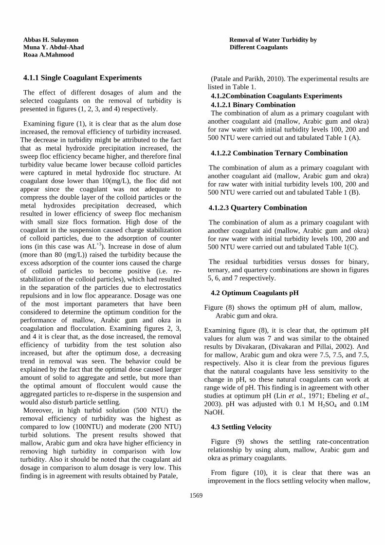
Abbas H. Sulaymon Removal of Water Turbidity by Muna Y. Abdul-Ahad Different Coagulants Roaa A.Mahmood
1569
4.1.1 Single Coagulant Experiments
The effect of different dosages of alum and the selected coagulants on the removal of turbidity is presented in figures (1, 2, 3, and 4) respectively.
Examining figure (1), it is clear that as the alum dose increased, the removal efficiency of turbidity increased. The decrease in turbidity might be attributed to the fact that as metal hydroxide precipitation increased, the sweep floc efficiency became higher, and therefore final turbidity value became lower because colloid particles were captured in metal hydroxide floc structure. At coagulant dose lower than 10(mg/L), the floc did not appear since the coagulant was not adequate to compress the double layer of the colloid particles or the metal hydroxides precipitation decreased, which resulted in lower efficiency of sweep floc mechanism with small size flocs formation. High dose of the coagulant in the suspension caused charge stabilization of colloid particles, due to the adsorption of counter ions (in this case was AL+3). Increase in dose of alum (more than 80 (mg/L)) raised the turbidity because the excess adsorption of the counter ions caused the charge of colloid particles to become positive (i.e. re-stabilization of the colloid particles), which had resulted in the separation of the particles due to electrostatics repulsions and in low floc appearance. Dosage was one of the most important parameters that have been considered to determine the optimum condition for the performance of mallow, Arabic gum and okra in coagulation and flocculation. Examining figures 2, 3, and 4 it is clear that, as the dose increased, the removal efficiency of turbidity from the test solution also increased, but after the optimum dose, a decreasing trend in removal was seen. The behavior could be explained by the fact that the optimal dose caused larger amount of solid to aggregate and settle, but more than the optimal amount of flocculent would cause the aggregated particles to re-disperse in the suspension and would also disturb particle settling. Moreover, in high turbid solution (500 NTU) the
removal efficiency of turbidity was the highest as compared to low (100NTU) and moderate (200 NTU) turbid solutions. The present results showed that mallow, Arabic gum and okra have higher efficiency in removing high turbidity in comparison with low turbidity. Also it should be noted that the coagulant aid dosage in comparison to alum dosage is very low. This finding is in agreement with results obtained by Patale,
(Patale and Parikh, 2010). The experimental results are
listed in Table 1. 4.1.2Combination Coagulants Experiments 4.1.2.1 Binary Combination The combination of alum as a primary coagulant with
another coagulant aid (mallow, Arabic gum and okra) for raw water with initial turbidity levels 100, 200 and 500 NTU were carried out and tabulated Table 1 (A).
4.1.2.2 Combination Ternary Combination
The combination of alum as a primary coagulant with another coagulant aid (mallow, Arabic gum and okra) for raw water with initial turbidity levels 100, 200 and 500 NTU were carried out and tabulated Table 1 (B).
4.1.2.3 Quartery Combination
The combination of alum as a primary coagulant with another coagulant aid (mallow, Arabic gum and okra) for raw water with initial turbidity levels 100, 200 and 500 NTU were carried out and tabulated Table 1(C).
The residual turbidities versus dosses for binary, ternary, and quartery combinations are shown in figures 5, 6, and 7 respectively.
4.2 Optimum Coagulants pH
Figure (8) shows the optimum pH of alum, mallow, Arabic gum and okra.
Examining figure (8), it is clear that, the optimum pH values for alum was 7 and was similar to the obtained results by Divakaran, (Divakaran and Pillai, 2002). And for mallow, Arabic gum and okra were 7.5, 7.5, and 7.5, respectively. Also it is clear from the previous figures that the natural coagulants have less sensitivity to the change in pH, so these natural coagulants can work at range wide of pH. This finding is in agreement with other studies at optimum pH (Lin et al., 1971; Ebeling et al., 2003). pH was adjusted with 0.1 M H2SO4 and 0.1M NaOH.
4.3 Settling Velocity
Figure (9) shows the settling rate-concentration relationship by using alum, mallow, Arabic gum and okra as primary coagulants.
From figure (10), it is clear that there was an improvement in the flocs settling velocity when mallow,

Journal of Engineering Volume 19 December 2013 Number 12
1570
Arabic gum and okra were used as coagulants aids in conjunction with alum as compared to alum alone. These coagulants make larger flocs with aluminum flocs in the water by bridging mechanism, finally settling them down and can be easily removed from turbid water; the experimental results are listed in Table 2 5.CONCLUSIONS
Based on the results of the experiments and tests conducted in this research, the following conclusions were found:-
1-The optimum doses of alum, mallow, Arabic gum and okra were 20, 2, 1 and 1 mg/L for100 NTU turbidity level, 35, 4, 2 and 3 mg/L for 200NTU turbidity level and 50, 8, 10 and 8 mg/L for 500 NTU turbidity level, respectively.
2-The optimum pH values for all the four coagulants (alum, mallow, Arabic gum and okra) were 7, 7.5, 7.5 and 7.5, respectively.
3-Using mallow, Arabic gum and okra as coagulant aids with alum (in binary, ternary and quartery combinations) cause the formation of flocs more quickly and increase the rate of sedimentation.
4- Natural coagulants (when used as primary coagulants) seem to be more effective at higher turbidity levels.
5- Natural coagulant significantly reduced the required dosage of alum between 15 to 30%, thereby reducing costs of treatment.
6. REFERENCES • A1-Wandawi, 1983, "Chemical composition of seeds of two okra cultivers Agric Food Chem",vol. 31:1355-1358. •Connachie, G. L., Folkard, G.K., Matawali, M. A. and Surtherland, J.P., 1999 “Field trials of appropriate hydraulic flocculation process” J. Water Research, 33 (6), 1425-1434.
•Divakaran R. and Pillai V. N. S. 2001 “Flocculation of Kaolinite suspensions in water by Chitosan”. J. Water Research. 35 (16), 3904-3908. •Ebeling, J.M., Sibrell, P., Ogden, S.,and Summerfelt, S., 2003, "Evaluation of chemical coagulation_/flocculation aids for the removal of
suspended solids and phosphorus from intensive recirculating aquaculture effluent discharge. Aquaculture Engineering", 29: 23-42. •Fatoki O. and Ogunfowokan, A., 2002, " Effect of coagulant treatment on the metal composition of raw water", 28(3):293-298.
•Foust A.S., Wenzel L.A., Clump C.W. and Andersen L.B 2004, Principles of Unit Design and Operation, 2nd
edition, New York: Addison Wesley, 2004. •Ghebremichael, K. A., 2004, "Moringa seed and pumice as natural alternative materials for drinking water treatment", Ph. D. Thesis, Royal Institute of Technology, Stockholm, Sweden. •Hoontrakul, S., 2006, "Evaluation of Coefficients Related to Flock Strength in Multilayer Floating Plastic Media Flocculator", Master’s thesis, Kasetsart University.
•Labib A., Abd El-Latife S. and Omran H., 1997 "Quality indices of Jew's mallow and spinach during frozen storage", Plant Foods for Human Nutrition vol.50, pp.333-347,
•Lin, S.D., Evans, R.L. and Beuscher, D.B., 1971. Algal Removal by Alum Coagulation. Illinois State Water Survey Division, Report of Investigation 68, Urbana, 1-19.
•Mackenzie, L.D., Cornwell, D.A., 1991. Introduction to Environmental Engineering. 2
nd Ed. McGraw Hill, New
York, 157-163. •Patale V. and Parikh P., 2010 "A Preliminary Study on Coccinia Indica Fruit Mucilage Extract as Coagulant-Flocculent for Turbid Water Treatment", PRAJÑĀ - Journal of Pure and Applied Sciences, Vol.
18, pp. 27-30.
•Sulaymon A.H, Ali A. M., and Al Naseri S.K., 2009,"Natural Organic Matter from Tigris River Water
in Baghdad, Iraq", Desalination, .245, pp.155-168.
•Williams, P. A. and Phillips, G. O. 1998 Gums and Stabilisers for the Food Industry 9 Royal Society of Chemistry, Cambridge UK. Special Publication No. 218.

Abbas H. Sulaymon Removal of Water Turbidity by Muna Y. Abdul-Ahad Different Coagulants Roaa A.Mahmood
1571
Table 1. The percentages of the coagulant doses.
A B C
Sample No.
Coagulants
Sample No.
Coagulants
Sample No.
Coagulants
1 85% of alum dose+15% one of
(mallow, gum okra) dose
1 85% of alum dose+7.5% two of
(mallow, gum okra) dose
1 85% of alum dose+5% of mallow, gum and okra doses
2 70% of alum dose+30% one of
(mallow, gum okra) dose
2 70% of alum dose+15% two of
(mallow, gum okra) dose
2 70% of alum dose+10% of
mallow, gum and okra doses
3 55% of alum dose+45% one of
(mallow, gum okra) dose
3 55% of alum dose+22.5% two of (mallow, gum okra)
dose
3 55% of alum dose+15% of
mallow, gum and okra doses
4 40% of alum dose+60% one of
(mallow, gum okra) dose
4 40% of alum dose+30% two of
(mallow, gum okra) dose
4 40% of alum dose+20% of
mallow, gum and okra doses
5 25% of alum dose+75% of one
(mallow, gum okra) dose
5 25% of alum dose+37.5% two of (mallow, gum okra)
dose
5 25% of alum dose+25% of
mallow, gum and okra doses
6 10% of alum dose+90% one of
(mallow, gum okra) dose
6 10% of alum dose+45% two of
(mallow, gum okra) dose
6 10% of alum dose+30% of
mallow, gum and okra doses

Journal of Engineering Volume 19 December 2013 Number 12
1572
Fig. 1 Plot residual turbidity vs. alum dose
Fig. 3 Plot residual turbidity vs. okra dose
Fig. 2 Plot residual turbidity vs. Arabic gum dose
Fig. 4 Plot residual turbidity vs. mallow dose

Abbas H. Sulaymon Removal of Water Turbidity by Muna Y. Abdul-Ahad Different Coagulants Roaa A.Mahmood
1573
Fig. 5 Plot residual turbidity vs. dose of alum in conjunction with mallow, Arabic gum and okra for raw water with initial turbidity100 NTU.
Fig. 6 Plot residual turbidity vs. dose of alum in conjunction with mallow, Arabic gum and okra for raw water with initial turbidity200 NTU.

Journal of Engineering Volume 19 December 2013 Number 12
1574
Fig. (7) Plot residual turbidity vs. dose of alum in conjunction with mallow, Arabic gum and okra for raw water with initial turbidity500 NTU.
Fig. 8 Determination of optimum pH with initial turbidity 100NTU.
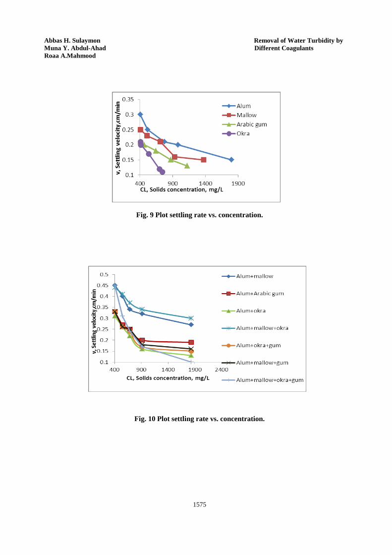
Abbas H. Sulaymon Removal of Water Turbidity by Muna Y. Abdul-Ahad Different Coagulants Roaa A.Mahmood
1575
Fig. 9 Plot settling rate vs. concentration.
Fig. 10 Plot settling rate vs. concentration.
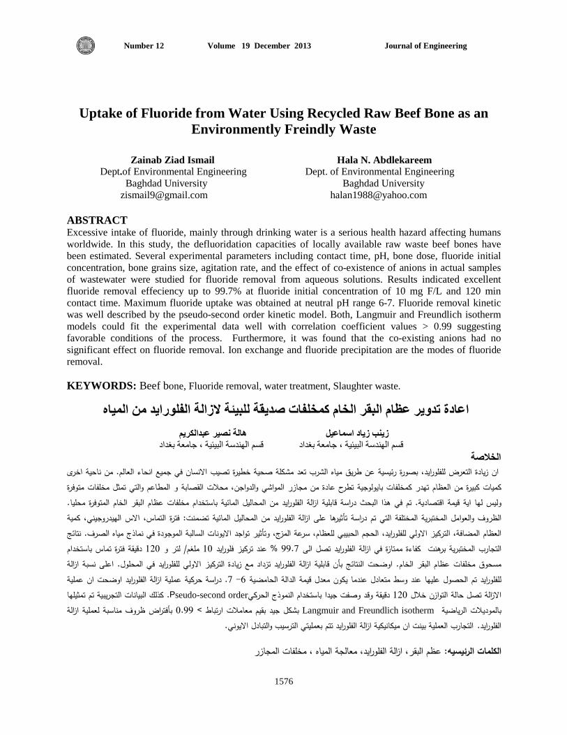
Journal of Engineering Volume 19 December 2013 Number 12
1576
Uptake of Fluoride from Water Using Recycled Raw Beef Bone as an Environmently Freindly Waste
Zainab Ziad Ismail Hala N. Abdlekareem Dept.of Environmental Engineering Dept. of Environmental Engineering Baghdad University Baghdad University [email protected] [email protected] ABSTRACT
Excessive intake of fluoride, mainly through drinking water is a serious health hazard affecting humans worldwide. In this study, the defluoridation capacities of locally available raw waste beef bones have been estimated. Several experimental parameters including contact time, pH, bone dose, fluoride initial concentration, bone grains size, agitation rate, and the effect of co-existence of anions in actual samples of wastewater were studied for fluoride removal from aqueous solutions. Results indicated excellent fluoride removal effeciency up to 99.7% at fluoride initial concentration of 10 mg F/L and 120 min contact time. Maximum fluoride uptake was obtained at neutral pH range 6-7. Fluoride removal kinetic was well described by the pseudo-second order kinetic model. Both, Langmuir and Freundlich isotherm models could fit the experimental data well with correlation coefficient values > 0.99 suggesting favorable conditions of the process. Furthermore, it was found that the co-existing anions had no significant effect on fluoride removal. Ion exchange and fluoride precipitation are the modes of fluoride removal. KEYWORDS: Beef bone, Fluoride removal, water treatment, Slaughter waste.
الزالة الفلورايد من المياه صديقة للبيئة كمخلفاتاعادة تدوير عظام البقر الخام هالة نصير عبدالكريمزينب زياد اسماعيل
بغدادة ، جامعة بيئيقسم الهندسة البيئية ، جامعة بغداد قسم الهندسة ال الخالصة
مشكلة صحية خطيرة تصيب االنسان في جميع انحاء العالم. من ناحية اخرى تعد يد، بصورة رئيسية عن طريق مياه الشرب ازيادة التعرض للفلور ان محالت القصابة و المطاعم والتي تمثل مخلفات متوفرة ،كميات كبيرة من العظام تهدر كمخلفات بايولوجية تطرح عادة من مجازر المواشي والدواجن
الخام المتوفرة محليا. البقر دراسة قابلية ازالة الفلورايد من المحاليل المائية باستخدام مخلفات عظام في هذا البحث قتصادية. تمقيمة ا ةايوليس لها ، كمية االس الهيدروجيني تماس،ال فترة: تضمنتزالة الفلورايد من المحاليل المائية ا ة تأثيرها علىالمختبرية المختلفة التي تم دراس ظروف والعواملال
نتائج .مياه الصرفنماذج االيونات السالبة الموجودة في تواجد ثير أ، وتسرعة المزجالعظام المضافة، التركيز االولي للفلورايد، الحجم الحبيبي للعظام، باستخدام ماست فترةدقيقة 120لتر و /مملغ 10عند تركيز فلورايد % 99.7في ازالة الفلورايد تصل الى ة ممتازةءكفا برهنتمختبرية الرب اتجال
الخام. اوضحت النتائج بأن قابلية ازالة الفلورايد تزداد مع زيادة التركيز االولي للفلورايد في المحلول. اعلى نسبة ازالة البقر مسحوق مخلفات عظامزالة الفلورايد اوضحت ان عملية ا عملية حركية دراسة. 7 -6عندما يكون معدل قيمة الدالة الحامضية متعادل تم الحصول عليها عند وسطللفلورايد
هاليتمثتم البيانات التجريبية كلذ. كPseudo-second orderدقيقة وقد وصفت جيدا باستخدام النموذج الحركي 120لتوازن خالل حالة ااالزالة تصل ازالة روف مناسبة لعمليةظبأفتراض 0.99مالت ارتباط > بشكل جيد بقيم معا Langmuir and Freundlich isotherm بالموديالت الرياضية
م بعمليتي الترسيب والتبادل االيوني.تميكانيكية ازالة الفلورايد تان التجارب العملية بينت .الفلورايد
عظم البقر، ازالة الفلورايد، معالجة المياه ، مخلفات المجازر: الرئيسيهالكلمات
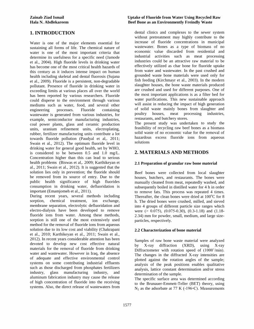
Zainab Ziad Ismail Uptake of Fluoride from Water Using Recycled Raw Hala N. Abdlekareem Beef Bone as an Environmently Freindly Waste
1577
1. INTRODUCTION
Water is one of the major elements essential for sustaining all forms of life. The chemical nature of water is one of the most important criteria that determine its usefulness for a specific need (Jamode et al., 2004). High fluoride levels in drinking water has become one of the most critical health hazards of this century as it induces intense impact on human health including skeletal and dental fluorosis (Sujana et al., 2009). Fluoride is a persistent, non-degradable pollutant. Presence of fluoride in drinking water in exceeding limits at various places all over the world has been reported by various researchers. Fluoride could disperse to the environment through various mediums such as water, food, and several other engineering processes. Fluoride containing wastewater is generated from various industries, for example, semiconductor manufacturing industries, coal power plants, glass and ceramic production units, uranium refinement units, electroplating, rubber, fertilizer manufacturing units contribute a lot towards fluoride pollution (Paudyal et al,. 2011; Swain et al., 2012). The optimum fluoride level in drinking water for general good health, set by WHO, is considered to be between 0.5 and 1.0 mg/L. Concentration higher than this can lead to serious health problems (Biswas et al,. 2009; Karthikeyan et al., 2011; Swain et al., 2012). It is suggested that the solution lies only in prevention; the fluoride should be removed from its source of entry. Due to the public health significance of high fluorides consumption in drinking water, defluoridation is important (Emamjomeh et al., 2011). During recent years, several methods including sorption, chemical treatment, ion exchange, membrane separation, electrolytic defluoridation and electro-dialysis have been developed to remove fluoride ions from water. Among these methods, sorption is still one of the most extensively used method for the removal of fluoride ions from aqueous solution due to its low cost and viability (Chakrapani et al., 2010; Karthikeyan et al., 2011; Swain et al., 2012). In recent years considerable attention has been devoted to develop new cost effective natural materials for the removal of fluoride from drinking water and wastewater. However in Iraq, the absence of adequate and effective environmental control systems on some contributing industrial effluents such as those discharged from phosphates fertilizers industry, glass manufacturing industry, and aluminum fabrication industry may cause the release of high concentration of fluoride into the receiving systems. Also, the direct release of wastewaters from
dental clinics and complexes to the sewer system without pretreatment may highly contribute to the increase of fluoride concentrations in municipal wastewater. Bones as a type of biomass of no economic value discarded from residential and industrial activities such as meat processing industries could be an attractive raw material to be effectively utilized as char bone for fluoride uptake from water and wastewater. In the past crushed and grounded waste bone materials were used only for fish feeding (Kirchmayr et al., 2003). In the modern slaughter houses, the bone waste materials produced are crushed and used for different purposes. One of the most important applications is as a filter bed for water purifications. This new sustainable approach will assist in reducing the impact of high generation of solid waste mainly bones from slaughter and poultry houses, meat processing industries, restaurants, and butchery stores. The present study was undertaken to study the feasibility of recycling raw beef bones as a biomass solid waste of no economic value for the removal of hazardous excess fluoride ions from aqueous solutions 2. MATERIALS AND METHODS 2.1 Preparation of granular raw bone material Beef bones were collected from local slaughter houses, butchers, and restaurants. The bones were manually cleaned from meat, repeatedly washed, and subsequently boiled in distilled water for 4 h in order to remove fats. This process was repeated 4 times. Thereafter, the clean bones were dried at 100oC for 8 h. The dried bones were crushed, milled, and sieved into 4 groups of different particle size ranges which were (˃ 0.075), (0.075-0.30), (0.3-1.18) and (1.18-2.34) mm for powder, small, medium, and large size-particles, respectively. 2.2 Characterization of bone material Samples of raw bone waste material were analyzed by X-ray diffraction (XRD), using X-ray Diffractometer with rotation speed of (1000˚/min). The changes in the diffracted X-ray intensities are plotted against the rotation angles of the sample; analysis of the peak positions enables qualitative analysis, lattice constant determination and/or stress determination of the sample. The specific surface area was determined according to the Brunauer-Emmett-Teller (BET) theory, using N2 as the adsorbate at 77 K (-196◦C). Measurements

Journal of Engineering Volume 19 December 2013 Number 12
1578
were conducted by surface analyzer type Q surf 9600. Before each run, the samples were exposed to a flow of 70% helium and 30% nitrogen for 1 h at 200°C, pore volume measured in the same apparatus using multi-point capability which allows complete analysis of sorption isotherm and total pore volume of the sample. Detection of the surface functional groups for the bone waste material before and after the uptake of fluoride was carried out by Fourier Transforms Infrared (FT-IR) technique using an EQUINOX FT-IR 55 spectrometer. The bone waste samples were grounded with 200 mg of KBr in a mortar and pressed into 10 mm diameter disks. The scanning range was 4000 - 400 cm-1. X-Ray Fluorescence analysis was carried out to determine the mineral compositions of the raw bone samples. The system consists of lithium silicon detector; measuring samples as a compressible oven dried- bone powder weighting 2-4 g. 2.3 Fluoride aqueous solution Fluoride stock solution of 1000 mg F/L was prepared by dissolving the desired amounts of sodium fluoride (NaF) in 1 liter of double distilled water, to obtain the desired concentration of fluoride ion in water. All working solutions of different fluoride concentrations were obtained by successive dilution of the stock solution. Batch mode operation was applied to study the removal of fluoride from aqueous samples. 2.4 Experimental procedure Fluoride uptake experiments were carried out by agitating 100 mL of the prepared fluoride solutions of various initial concentrations contained in 250 mL-plastic Erlenmeyer flasks at room temperature. After proper pre-determined time intervals, samples of supernatant were filtered and the filtrates were analyzed to determine the residual fluoride concentration. All experiments were carried out in replicate. In order to investigate the effect of pH on fluoride removal, the pH was adjusted to different values over a range of 3-11 by the addition of either 1M NaOH or 1M HCl. Additional sets of experiments were carried out to investigate the effects of particle size of bone granules. Also, the effects of the initial concentration of fluoride (5, 10, 25, and 35 mg F/L) as well as the agitation rate on the removal effeciency were considered in this study.
3 RESULTS AND DISSCUSION 3.1 Chemical composition and characterization The elemental chemical analysis of bone samples revealed that the bone char was mainly composed of Ca and P as well as traces of Na, Mg, Al, Fe, and Zn. Results of (XRF) analysis after fluoride removal revealed that the concentration of the main components; calcium and phosphorus were reduced indicating the involvement of these elements in the fluoride uptake process. Surface area values determined by Brunauer-Emmett-Teller (BET) method revealed that the surface area values decreased with increasing the particle size as given in Table 1. Table 1 Surface area and pore volume of beef bone
Particle size range, (mm)
Size Surface area,
(m2/g)
Pore volume, (m3/g)
< 0.075 Powder 6.30 0.0080 0.075-0.30 Small 3.60 0.0044 0.30-1.18 Medium 1.60 0.0014 1.18-2.34 Small 1.18 0.0014
XRD patterns of the raw waste bone (RWB) samples indicate the presence of calcium hydroxyapatite, [Cal0 (PO4)6 (OH)2] (HAP) as the major component of the raw beef bone samples. For the Fourier infrared spectroscopy (FT-IR), the characteristics bands of the natural raw bones before and after the fluoride uptake at pH 7 were used to assess the changes in the functional groups of the biomass material. The spectra (Fig.1) were plotted using the same scale on the transmittance axis for all sorbents before and after fluoride uptake. The broad band from 3600 to 2600 cm-1 indicates the presence of OH- groups. The sorption around 3565 cm-1 was OH- associated by hydrogen bond stretch, which is the typical band for natural hydroxylapatite (HAP) (Mikhaylova et al., 2006). The peaks at about 1028, 958, 603, and 559 cm-1 arise from different vibrations of PO4
-3 group. Peaks at about 1456 and 1419 cm-1 and near 871 could be attributed to CO3
-2 group. However, the change of PO4
-3 and CO3- peaks were
observed indicating the involvement of these groups in the fluoride removal process.
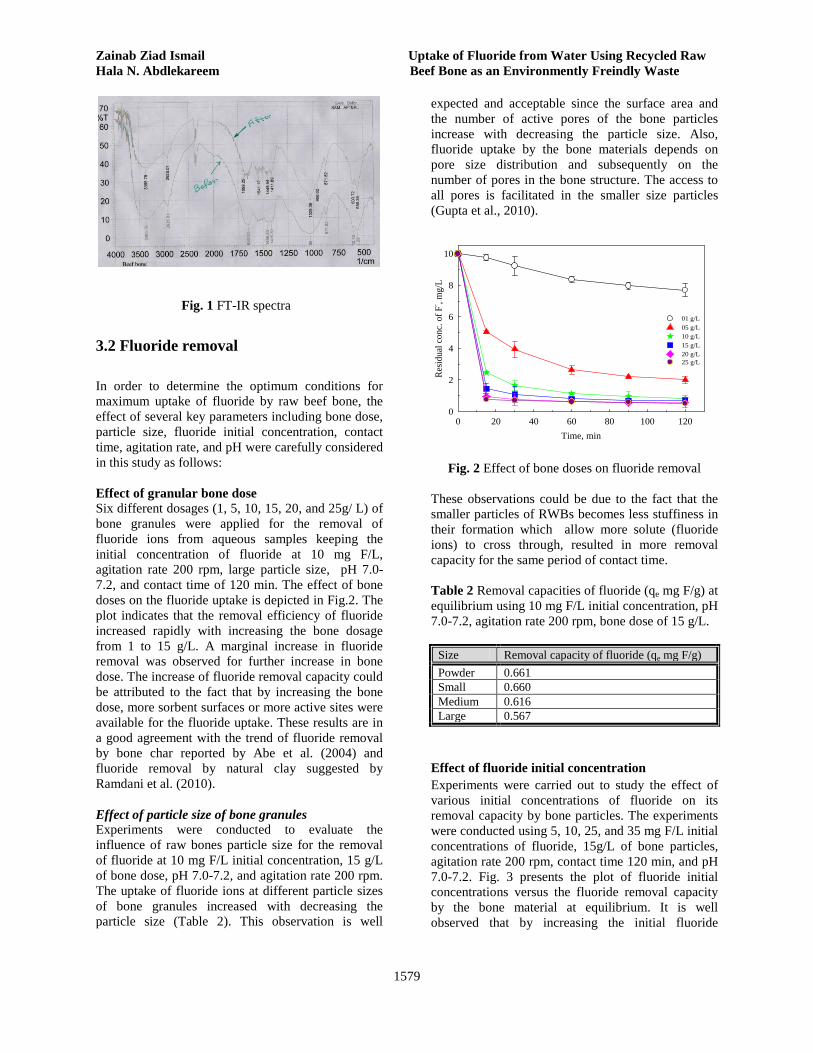
Zainab Ziad Ismail Uptake of Fluoride from Water Using Recycled Raw Hala N. Abdlekareem Beef Bone as an Environmently Freindly Waste
1579
Fig. 1 FT-IR spectra
3.2 Fluoride removal In order to determine the optimum conditions for maximum uptake of fluoride by raw beef bone, the effect of several key parameters including bone dose, particle size, fluoride initial concentration, contact time, agitation rate, and pH were carefully considered in this study as follows: Effect of granular bone dose Six different dosages (1, 5, 10, 15, 20, and 25g/ L) of bone granules were applied for the removal of fluoride ions from aqueous samples keeping the initial concentration of fluoride at 10 mg F/L, agitation rate 200 rpm, large particle size, pH 7.0-7.2, and contact time of 120 min. The effect of bone doses on the fluoride uptake is depicted in Fig.2. The plot indicates that the removal efficiency of fluoride increased rapidly with increasing the bone dosage from 1 to 15 g/L. A marginal increase in fluoride removal was observed for further increase in bone dose. The increase of fluoride removal capacity could be attributed to the fact that by increasing the bone dose, more sorbent surfaces or more active sites were available for the fluoride uptake. These results are in a good agreement with the trend of fluoride removal by bone char reported by Abe et al. (2004) and fluoride removal by natural clay suggested by Ramdani et al. (2010). Effect of particle size of bone granules Experiments were conducted to evaluate the influence of raw bones particle size for the removal of fluoride at 10 mg F/L initial concentration, 15 g/L of bone dose, pH 7.0-7.2, and agitation rate 200 rpm. The uptake of fluoride ions at different particle sizes of bone granules increased with decreasing the particle size (Table 2). This observation is well
expected and acceptable since the surface area and the number of active pores of the bone particles increase with decreasing the particle size. Also, fluoride uptake by the bone materials depends on pore size distribution and subsequently on the number of pores in the bone structure. The access to all pores is facilitated in the smaller size particles (Gupta et al., 2010).
Time, min0 20 40 60 80 100 120
Resid
ual c
onc.
of F
- , mg/
L
0
2
4
6
8
10
01 g/L05 g/L10 g/L 15 g/L 20 g/L25 g/L
Fig. 2 Effect of bone doses on fluoride removal These observations could be due to the fact that the smaller particles of RWBs becomes less stuffiness in their formation which allow more solute (fluoride ions) to cross through, resulted in more removal capacity for the same period of contact time. Table 2 Removal capacities of fluoride (qe mg F/g) at equilibrium using 10 mg F/L initial concentration, pH 7.0-7.2, agitation rate 200 rpm, bone dose of 15 g/L.
Size Removal capacity of fluoride (qe mg F/g) Powder 0.661 Small 0.660 Medium 0.616 Large 0.567
Effect of fluoride initial concentration Experiments were carried out to study the effect of various initial concentrations of fluoride on its removal capacity by bone particles. The experiments were conducted using 5, 10, 25, and 35 mg F/L initial concentrations of fluoride, 15g/L of bone particles, agitation rate 200 rpm, contact time 120 min, and pH 7.0-7.2. Fig. 3 presents the plot of fluoride initial concentrations versus the fluoride removal capacity by the bone material at equilibrium. It is well observed that by increasing the initial fluoride
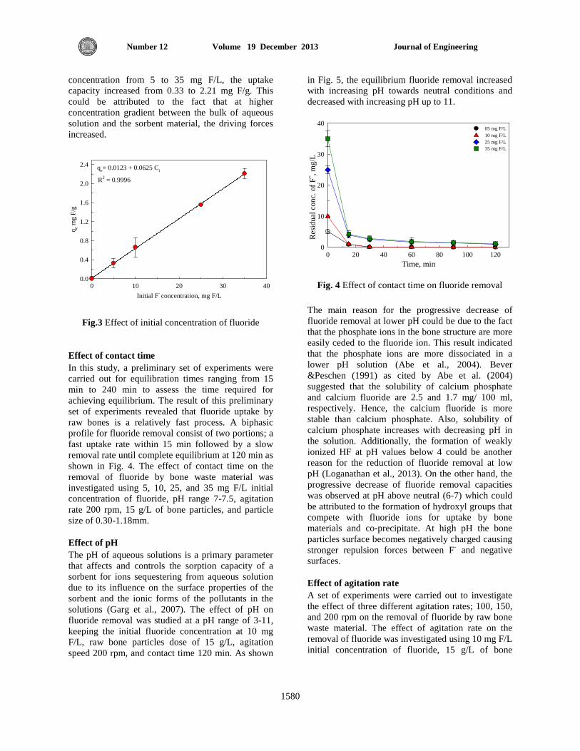
Journal of Engineering Volume 19 December 2013 Number 12
1580
concentration from 5 to 35 mg F/L, the uptake capacity increased from 0.33 to 2.21 mg F/g. This could be attributed to the fact that at higher concentration gradient between the bulk of aqueous solution and the sorbent material, the driving forces increased.
qe= 0.0123 + 0.0625 Ci
Initial F- concentration, mg F/L0 10 20 30 40
q e mg
F/g
0.0
0.4
0.8
1.2
1.6
2.0
2.4
R2 = 0.9996
Fig.3 Effect of initial concentration of fluoride
Effect of contact time In this study, a preliminary set of experiments were carried out for equilibration times ranging from 15 min to 240 min to assess the time required for achieving equilibrium. The result of this preliminary set of experiments revealed that fluoride uptake by raw bones is a relatively fast process. A biphasic profile for fluoride removal consist of two portions; a fast uptake rate within 15 min followed by a slow removal rate until complete equilibrium at 120 min as shown in Fig. 4. The effect of contact time on the removal of fluoride by bone waste material was investigated using 5, 10, 25, and 35 mg F/L initial concentration of fluoride, pH range 7-7.5, agitation rate 200 rpm, 15 g/L of bone particles, and particle size of 0.30-1.18mm. Effect of pH The pH of aqueous solutions is a primary parameter that affects and controls the sorption capacity of a sorbent for ions sequestering from aqueous solution due to its influence on the surface properties of the sorbent and the ionic forms of the pollutants in the solutions (Garg et al., 2007). The effect of pH on fluoride removal was studied at a pH range of 3-11, keeping the initial fluoride concentration at 10 mg F/L, raw bone particles dose of 15 g/L, agitation speed 200 rpm, and contact time 120 min. As shown
in Fig. 5, the equilibrium fluoride removal increased with increasing pH towards neutral conditions and decreased with increasing pH up to 11.
Time, min0 20 40 60 80 100 120
Resid
ual c
onc.
of F
- , mg/
L
0
10
20
30
4005 mg F/L 10 mg F/L25 mg F/L35 mg F/L
Fig. 4 Effect of contact time on fluoride removal
The main reason for the progressive decrease of fluoride removal at lower pH could be due to the fact that the phosphate ions in the bone structure are more easily ceded to the fluoride ion. This result indicated that the phosphate ions are more dissociated in a lower pH solution (Abe et al., 2004). Bever &Peschen (1991) as cited by Abe et al. (2004) suggested that the solubility of calcium phosphate and calcium fluoride are 2.5 and 1.7 mg/ 100 ml, respectively. Hence, the calcium fluoride is more stable than calcium phosphate. Also, solubility of calcium phosphate increases with decreasing pH in the solution. Additionally, the formation of weakly ionized HF at pH values below 4 could be another reason for the reduction of fluoride removal at low pH (Loganathan et al., 2013). On the other hand, the progressive decrease of fluoride removal capacities was observed at pH above neutral (6-7) which could be attributed to the formation of hydroxyl groups that compete with fluoride ions for uptake by bone materials and co-precipitate. At high pH the bone particles surface becomes negatively charged causing stronger repulsion forces between F- and negative surfaces. Effect of agitation rate A set of experiments were carried out to investigate the effect of three different agitation rates; 100, 150, and 200 rpm on the removal of fluoride by raw bone waste material. The effect of agitation rate on the removal of fluoride was investigated using 10 mg F/L initial concentration of fluoride, 15 g/L of bone
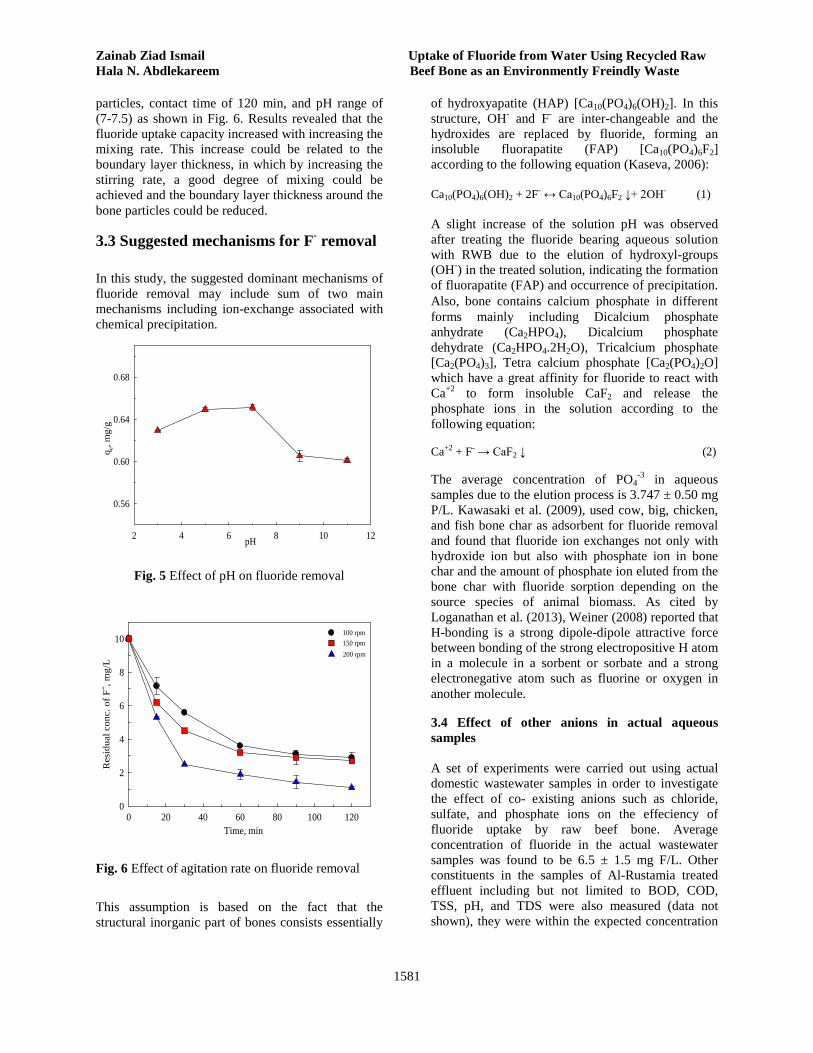
Zainab Ziad Ismail Uptake of Fluoride from Water Using Recycled Raw Hala N. Abdlekareem Beef Bone as an Environmently Freindly Waste
1581
particles, contact time of 120 min, and pH range of (7-7.5) as shown in Fig. 6. Results revealed that the fluoride uptake capacity increased with increasing the mixing rate. This increase could be related to the boundary layer thickness, in which by increasing the stirring rate, a good degree of mixing could be achieved and the boundary layer thickness around the bone particles could be reduced.
3.3 Suggested mechanisms for F- removal In this study, the suggested dominant mechanisms of fluoride removal may include sum of two main mechanisms including ion-exchange associated with chemical precipitation.
pH2 4 6 8 10 12
q e, m
g/g
0.56
0.60
0.64
0.68
Fig. 5 Effect of pH on fluoride removal
Time, min0 20 40 60 80 100 120
Res
idua
l con
c. o
f F- , m
g/L
0
2
4
6
8
10100 rpm
200 rpm 150 rpm
Fig. 6 Effect of agitation rate on fluoride removal This assumption is based on the fact that the structural inorganic part of bones consists essentially
of hydroxyapatite (HAP) [Ca10(PO4)6(OH)2]. In this structure, OH- and F- are inter-changeable and the hydroxides are replaced by fluoride, forming an insoluble fluorapatite (FAP) [Ca10(PO4)6F2] according to the following equation (Kaseva, 2006): Ca10(PO4)6(OH)2 + 2F- ↔ Ca10(PO4)6F2 ↓+ 2OH- (1) A slight increase of the solution pH was observed after treating the fluoride bearing aqueous solution with RWB due to the elution of hydroxyl-groups (OH-) in the treated solution, indicating the formation of fluorapatite (FAP) and occurrence of precipitation. Also, bone contains calcium phosphate in different forms mainly including Dicalcium phosphate anhydrate (Ca2HPO4), Dicalcium phosphate dehydrate (Ca2HPO4.2H2O), Tricalcium phosphate [Ca2(PO4)3], Tetra calcium phosphate [Ca2(PO4)2O] which have a great affinity for fluoride to react with Ca+2 to form insoluble CaF2 and release the phosphate ions in the solution according to the following equation:
Ca+2 + F- → CaF2 ↓ (2)
The average concentration of PO4-3 in aqueous
samples due to the elution process is 3.747 ± 0.50 mg P/L. Kawasaki et al. (2009), used cow, big, chicken, and fish bone char as adsorbent for fluoride removal and found that fluoride ion exchanges not only with hydroxide ion but also with phosphate ion in bone char and the amount of phosphate ion eluted from the bone char with fluoride sorption depending on the source species of animal biomass. As cited by Loganathan et al. (2013), Weiner (2008) reported that H-bonding is a strong dipole-dipole attractive force between bonding of the strong electropositive H atom in a molecule in a sorbent or sorbate and a strong electronegative atom such as fluorine or oxygen in another molecule.
3.4 Effect of other anions in actual aqueous samples A set of experiments were carried out using actual domestic wastewater samples in order to investigate the effect of co- existing anions such as chloride, sulfate, and phosphate ions on the effeciency of fluoride uptake by raw beef bone. Average concentration of fluoride in the actual wastewater samples was found to be 6.5 ± 1.5 mg F/L. Other constituents in the samples of Al-Rustamia treated effluent including but not limited to BOD, COD, TSS, pH, and TDS were also measured (data not shown), they were within the expected concentration

Journal of Engineering Volume 19 December 2013 Number 12
1582
ranges in wastewater. The concentrations of conventional anions in wastewater samples including SO4
-2, Cl-, and PO4-3 were also determined as the co-
existing anions which may compete with the fluoride ions for available sorption sites. The average concentrations of SO4
-2, Cl-, and PO4-3 were found to
be 200 ± 3.4, 20 ± 3.2, and 12 ± 0.8 mg/L, respectively However, characteristics of Al-Rustamia wastewater samples in regard with fluoride concentration revealed that the average concentration of F- ions in the influent is higher than the typical allowable concentration. In fact, none of the conventional treatment units including primary settling and secondary bio- treatment is convenient for fluoride removal. Therefore, reduction in fluoride concentration is unexpected in the treated effluent. Results revealed that the removal efficiencies of defluoridation process by beef bone granules are 98.5 ± 0.8 and 99.0 ± 0.2 at initial concentrations of 5 and 6.5 mg F/L for the synthetic and actual samples, respectively. It is obvious that there was no significant influence of competing anions (SO4
-2, Cl-, and PO4
-3) on F- removal capacity, which could be attributed to the availability of plenty of exchangeable and sorption sites on this natural material. However, Loganathan et al., (2013) reported that the extent of the competition depends on the relative concentrations of the ions and their affinity for the sorbent. Meenakshi & Viswanathan (2007) suggested that increased concentrations of Cl-, SO4
-2, NO3-, Br-, and HCO3
- decreased F- uptake by anion exchange resin which adsorbs anions by an ion exchange mechanism, whereas these anions had no effect on fluoride sorption by a chelating resin which adsorbed F- selectively by a H-bonding mechanism. Raichur & Basu (2001) found that F- removal by a mixture of naturally occurring rare earth oxides was not significantly affected by the presence of SO4
-2 and NO3
- in water at a concentration equal to that of F- ions. Solangi et al., (2010) studied the removal of fluoride ions by a thio-urea incorporated amberlite resin in the presence of PO4
-3, Cl-, SO4-2, Br-, NO3
-, NO2
-, HCO3-, and CO3
- at 5 times the molar concentration of F- and observed that Br-, PO4
-3 and NO2
- had little interference with F-, but the other anions had no interference. Loganathan et al., (2013) concluded that the non-specifically adsorbing anions (e.g. Cl-, NO3
-) don’t compete with F- for sorption by specific adsorption. Only anions that are sorbed by specific sorption (e.g. selenate, arsenate, phosphate) compete with F- for sorption.
3.5 Sorption isotherms of Fluoride The sorption isotherms indicate how the sorption molecules distribute between the liquid phase and solid phase at equilibrium. In this study, the experimental data were fitted to the typical Freundlich and Langmuir models. The linear form of Freundlich and Langmuir models are represented by Eqs. 3 and 4, respectively:
Ln (qe) = log K + (1/n) ln Ce (3)
Ce / (qe) = (1/b qm) + (1/ qm) Ce (4)
Where qe (mg F/g) is the amount of F- adsorbed per unit weight of bone at equilibrium, Ce is the residual concentration of fluoride in the aqueous solution at equilibrium (mg F/L), qm is the amount of F- adsorbed per unit of adsorbent for a monolayer surface (mg F/g), K and n are Freundlich constants, b is the Langmuir constant (L/mg). The estimated parameters for Freundlich and Langmuir sorption isotherms are given in Table 3.
Table 3 Estimated parameters for Freundlich and Langmuir sorption isotherms
Estimated parameters Freundlich isotherm Langmuir isotherm K n R2 qm b R2
0.074 1.092 0.9982 1.435 0.054 0.9939
3.6 Kinetic study Kinetic models were applied in this study to test the experimental data in order to describe the behavior of sorption process for further scale-up. The kinetic models are pseudo-first order, pseudo-second order, and intra-particle diffusion model. Pseudo-first order is generally applicable over the first 20-30 min of the sorption process (Ncibi et al., 2008). The linear form of this kinetic model can be described as follows: ln(qe-qt) =ln qe – k1t The pseudo-second order predicts the behavior of the chemical sorption over the entire time of sorption; this model is based on the adsorption capacity of the adsorbent (Ncibi et al., 2008). The linearized form of pseudo-second order is: t/qt = (1/k2qe
2) + (t/qe)

Zainab Ziad Ismail Uptake of Fluoride from Water Using Recycled Raw Hala N. Abdlekareem Beef Bone as an Environmently Freindly Waste
1583
The intra-particle diffusion model describes the transfer of fluoride ions from the bulk solution to the interior surface of the sorbent as follows: qt = kp (t)0.5 Pseudo-first order model Straight-line plots of ln (qe-qt) versus time were used to determine the rate constants k1 for different fluoride concentrations as shown in Fig. 7. Although these plots show good linearity, the values of theoretical removal capacities (qe, Tho) are different from the experimental ones (qe, ex) as given in Table 4.
Time, min0 10 20 30
Ln (q
e-qt)
-6
-4
-2
005 mg F/L10 mg F/L 25 mg F/L 35 mg F/L
Fig. 7 First order plots for F- removal by raw beef
bone
Table 4 Kinetic parameters for the applied kinetic models using raw beef bone
Fluoride concentration
(mg F-/L)
Pseudo-first order model
qex (mg/g) k1,
(min-1) qe,Tho
(mg/g) R2
35 0.1195 0.391 0.9398 1.658 05 0.1133 0.980 0.9553 1.164 10 0.1957 0.603 0.9891 0.497 05 0.1559 0.265 0.9740 0.248
Pseudo-second order model
k2, (g mg-1 min-1)
qe,Tho
(mg/g) R2
35 0.278 1.718 0.9992 05 0.286 1.224 0.9985 10 1.140 0.507 0.9991 05 8.604 0.249 0.9991
Pseudo-second order model The plot of t/qt versus time must give a straight line if pseudo- second order kinetic model is applicable and qe and k2 can be determined from the slope and intercept of the plot as presented in Fig. 8. Better linearity than pseudo-first order was obtained for these plots as shown in Table 4 with correlation coefficients slightly higher than those of pseudo-first order model. Also, in this model, the values of qe, Tho are in a good agreement with the experimental values of qe, ex. Accordingly, the pseudo-second order model could be considered as the best model that can be used for predicting the kinetic of fluoride sorption process in this study.
Time, min0 20 40 60 80 100 120
t/qt
0
100
200
300
400
50005 mg F/L 10 mg F/L 25 mg F/L 35 mg F/L
Fig. 8 Second order plots for F- removal by raw beef
bone
Intra-particle diffusion model Demir et al. (2002) suggested that for intra-particle diffusion model, a plot of qt versus t0.5 should be linear if intra-particle diffusion is involved in the sorption process; and if this line passes through the origin, intra-particle diffusion is the rate controlling step. If the plot does not pass through the origin, it is indicative of some degree of boundary layer control and further shows that the intra-particle diffusion is not the only rate limiting step and other kinetic models may control the rate of adsorption, all of which may be functioning simultaneously. Based on this fact, the plot of qt versus t0.5 in this study gave straight lines as shown in Fig. 9 indicating that the sorption process was controlled by intra-particle diffusion. However, the straight lines do not pass through the origin which means that both the surface sorption and intra-particle diffusion are involved in the complex sorption process of fluoride to the raw beef bone material.

Journal of Engineering Volume 19 December 2013 Number 12
1584
t0.5, min0.5
0 2 4 6 8 10 12 14
q t, m
g/g
0.0
0.4
0.8
1.2
1.6
2.0
2.4 05 mg F/L 10 mg F/L 25 mg F/L 35 mg F/L
Fig. 9 Intra-particle diffusion model for F- removal
by raw beef bone
4. CONCLUSION
This study examined the potential of fluoride removal from aqueous solution using raw waste beef bone Characterizations of the bone material indicated the presence of calcium hydroxyapatite, [Cal0 (PO4)6 (OH)2] (HAP) as the major component of the beef bone. This study has demonstrated that the beef bone waste materials can be used efficiently for fluoride removal from aqueous solutions. Maximum removal effeciency of fluoride using powder bone dose 15 g/L was 99.7 at pH 7.0, fluoride initial concentration 10 mg F/L, and agitation rate of 200 rpm. The extent of fluoride removal was dependent on initial fluoride concentrations, pH, contact time, bone dose, and agitation rate. Maximum fluoride uptake was obtained at neutral pH range of 6-7. Results revealed that the fluoride removal capacity of the powder sized particles (< 0.075 mm) was found to be the highest among the four tested ranges of particle size. Both, Langmuir and Freundlich isotherm models could fit the experimental data well with correlation coefficient values > 0.99 suggesting favorable conditions of the process. Fluoride removal kinetic indicated the equilibrium of fluoride uptake was within 120 min, and it is well described by the pseudo-second order kinetic model.
ACKNOWLEDGEMENTS This work was funded by the Ministry of Municipality, Iraq. The authors are grateful to the
Ministry of Science and Technology staff for the technical support. REFERENCES • Abe, I., Iwasaki, S., Tokimoto, T., Kawasaki, N., Nakamura, T., and Tanada, S., 2004. Adsorption of fluoride ions onto carbonaceous materials. Journal of Colloid and Interface Science. 275, 35-39. • Bever, J., and Peschen, N., 1991. Phosphorus-Elimination by Simultaneous Precipitation with Hydrated Lime - Recent Findings. Wasserwirtschaft, 81, 66-70. • Biswas, K., Gupta, K., and Ghosh, U.C., 2009. Adsorption of fluoride by hydrous iron (III)–tin(IV) bimetal mixed oxide from the aqueous solutions. Chemical Engineering Journal. 149, 196-206. • Chakrapani, C.H., Sureshbabu, C.H., Vani K.N.K., and Somasekhararao, K., 2010. Adsorption Kinetics for the Removal of Fluoride from Aqueous Solution by Activated Carbon Adsorbents Derived from the Peels of Selected Citrus Fruits. Journal of Chemistry. 7, 419-427. •Demir, A., Gunay, A., and Debik, E., 2002. Ammonuim removal from aqueous solution by ion exchange using packed bed natural zeolite, Water Research. 28, 329-336.
• Emamjomeh, M.M., Sivakumar, M., and Varyani, A.S., 2011. Analysis and the understanding of fluoride removal mechanisms by an electro coagulation/flotation (ECF) process. Desalination. 275, 102-106. • Garg, U.K., Kaur, M.P., Garg, V.K., and Suda, D., 2007. Removal of hexavalent chromium from aqueous solution by agricultural waste biomass, Journal of Hazardous Materials. 140, 60-˗68. • Gupta, V.K., Rastogi, A., and Nayak, A., 2010. Adsorption studies on the removal of hexavalent chromium from aqueous solution using a low cost fertilizer industry waste material. Journal of Colloid and Interface Science. 342, 135-141. • Jamode, A.V., Sapkal, V.S., and Jamode, V.S., 2004. Defluoridation of water using inexpensive adsorbents. Journal of Indian Institute Science. 84, 163-171.
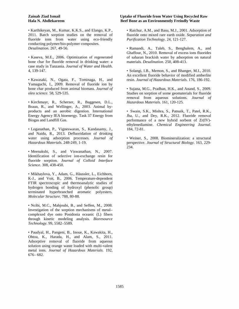
Zainab Ziad Ismail Uptake of Fluoride from Water Using Recycled Raw Hala N. Abdlekareem Beef Bone as an Environmently Freindly Waste
1585
• Karthikeyan, M., Kumar, K.K.S., and Elango, K.P., 2011. Batch sorption studies on the removal of fluoride ions from water using eco-friendly conducting polymer/bio-polymer composites. Desalination. 267, 49-56. • Kaseva, M.E., 2006. Optimization of regenerated bone char for fluoride removal in drinking water: a case study in Tanzania. Journal of Water and Health. 4, 139-147. • Kawasaki, N., Ogata, F., Tominaga, H., and Yamaguchi, I., 2009. Removal of fluoride ion by bone char produced from animal biomass. Journal of oleo science. 58, 529-535. • Kirchmayr, R., Scherzer, R., Baggesen, D.L., Braun, R., and Wellinger, A., 2003. Animal by-products and an aerobic digestion. International Energy Agency IEA bioenergy. Task 37 Energy from Biogas and Landfill Gas. • Loganathan, P., Vigneswaran, S., Kandasamy, J., and Naidu, R., 2013. Defluoridation of drinking water using adsorption processes. Journal of Hazardous Materials. 248-249, 1-19. • Meenakshi, S., and Viswanathan, N., 2007. Identification of selective ion-exchange resin for fluoride sorption. Journal of Colloid Interface Science. 308, 438-450. • Mikhaylova, Y., Adam, G., Häussler, L., Eichhorn, K-J., and Voit, B., 2006. Temperature-dependent FTIR spectroscopic and thermoanalytic studies of hydrogen bonding of hydroxyl (phenolic group) terminated hyperbranched aromatic polyesters. Molecular Structure. 788, 80-88. • Ncibi, M.C., Mahjoubi, B., and Seffen, M., 2008. Investigation of the sorption mechanisms of metal–complexed dye onto Posidonia oceanic (L) fibers through kinetic modeling analysis. Bioresource Technology. 99, 5582–5589. • Paudyal, H., Pangeni, B., Inoue, K., Kawakita, H., Ohtoa, K., Harada, H., and Alam, S., 2011. Adsorptive removal of fluoride from aqueous solution using orange waste loaded with multi-valent metal ions. Journal of Hazardous Materials. 192, 676– 682.
• Raichur, A.M., and Basu, M.J., 2001. Adsorption of fluoride onto mixed rare earth oxide. Separation and Purification Technology. 24, 121-127. • Ramandi, A., Taleb, S., Benghalem, A., and Ghaffour, N., 2010. Removal of excess ions fluorides of saharan brackish water by adsorption on natural materials. Desalination. 250, 408-413. • Solangi, I.B., Memon, S., and Bhanger, M.I., 2010. An excellent fluoride behavior of modified amberlite resin. Journal of Hazardous Materials. 176, 186-192. • Sujana, M.G., Pradhan, H.K., and Anand, S., 2009. Studies on sorption of some geomaterials for fluoride removal from aqueous solutions. Journal of Hazardous Materials. 161, 120-125. • Swain, S.K., Mishra, S., Patnaik, T., Patel, R.K., Jha, U., and Dey, R.K., 2012. Fluoride removal performance of a new hybrid sorbent of Zr(IV)-ethylenediamine. Chemical Engineering Journal. 184, 72-81. • Weiner, S., 2008. Biomineralization: a structural perspective. Journal of Structural Biology. 163, 229-234.

Journal of Engineering Volume 19 December 2013 Number 12
1586
Design and Implementation of Single-Phase Boost PFC Converter
Abstract—In this paper, a single-phase boost type ac-dc converter with power factor correction
(PFC) technique is designed and implemented. A current mode control at a constant switching
frequency is used as a control strategy for PFC converter. The PFC converter is a single-stage single-
switch boost converter that uses a current shaping technique to reshape the non-sinusoidal input
current drawn by the bulky capacitor in the conventional rectifier. This technique should provide an
input current with almost free-harmonics, comply with the IEC61000-3-2 limits, and a system
operates with near unity power factor. The other function of the boost converter that should be
accomplished is to provide a regulated DC output voltage. The complete designed system is
simulated in MATLAB/SIMULINK and a hardware prototype has been built using analog devices.
Simulation results and experimental results are presented to validate the proposed system.
Keywords— Boost converter, power factor correction, power quality.
افع احادي انطىر بتقنيت تصحيح يعايم انقذرةتصيى وتنفيذ يحىل ر
. سيرى اسرخذاو سيطشج سافع ادادي انطوس رو ذقيح ذصذيخ يعايم انقذسج يذولوذفيز سيرى ذصيى انثذث،: في زا انخالصت
نهذول. انذول انصذخ نعايم انقذسج سيكو يذول سافع نهفونريح ادادي انشدهح كاسرشاذيجيحط انرياس ترشدد ثاتد
وانزي يسرخذو ذقيح ذشكيم انرياس نيعيذ ذشكيم ذياس االدخال انالجيثي انسذوب تواسطح انرسعح انكثيشج في وادادي انفراح
، وذوفش كزنك IEC61000-3-2ويهرزو تقاييس ال انقوو انرقهيذي. يجة ا ذوفش ز انرقيح ذياس ادخال خال ي انروافقياخ
يفح االخشى نهذول انشافع انري يجة ا ذذقق ي ذوفيش فونريح خشوج ظايا يعم تعايم قذسج قشية ي انوادذ. انوظ
وسيرى تاء ورج عهي ن تاسرخذاو انذوائش MATLAB/SIMULINKيذاكاج انظاو ككم تاسرخذاو يظح. سيرى
انراثهح. سيرى سفذ رائج انذاكاج وانرائج انعهيح نرأييذ انظاو انقرشح.
.ةىل رافع، تصحيح يعايم انقذر، جىدة انقذرانكهاث انزئيسيت: يح
Prof. Dr. Jafar H. Alwash, Department of Electrical Engineering
College of Engineering
Baghdad University
Email:[email protected]
Asst. Prof. Dr. Turki K. Hassan, Department of Electrical Engineering
College of Engineering Al-Mustansiriyah University
Email: [email protected]
Asst. Lect. Raed F. Abbas, Department of Electrical Engineering
College of Engineering
Baghdad University
Email: [email protected]
و.و. رائذ فؤاد عباس
قسى انهنذست انكهزبائيت
كهيت انهنذست/جايعت بغذاد
أ.و.د. تزكي كحيىش حسن
قسى انهنذست انكهزبائيت
انستنصزيتكهيت انهنذست/انجايعت
أ.د. جعفز حيذ عهىش
قسى انهنذست انكهزبائيت
كهيت انهنذست/جايعت بغذاد
Jafar H. Alwash Design and Implementation of
Turki K. Hassan Single-Phase Boost PFC Converter
Raed F. Abbas
1587
1. INTRODUCTION Power factor correction technique has been
widely used in ac-dc switching-mode power supply
to improve input power quality and to meet the
requirement of international standards [K.-M. Ho,
2010]. Power supplies without PFC capability usually
contain a diode-bridge rectifiers, which are largely used
to provide dc source for the load, cause serious
harmonic problem of power quality due to the
nonlinearity of the diode rectifier and the capacitive
filter (between the rectifier and the load). This behavior
causes to draw non-sinusoidal input currents leading
to inject harmonics into the utility lines and thus
producing a current distortion. These effects will
draw the system performance to lower power factor
then reducing the maximum power available from
the power lines and reducing the efficiency.
Power supplies with PFC capability usually
contain a converter whose first function is to reduce
the harmonics to ensure a near unity power factor at
the input. For medium to high power, boost
converter operated in continuous conduction mode
(CCM) is the usual form of a PFC converter [G.
Chu, 2009 - O. Garcia, 2003] with average current
mode control (ACM). A fast control loop, known as
inner current loop, is used such that the input
current follows the same sinusoidal waveform as the
input voltage. The PFC converter is often
terminated with a storage capacitor to provide a
tightly regulated output voltage to the eventual load.
This is the second function of the PFC converter
achieved through an outer voltage loop.
In ACM control technique [L. H. Dixon, 1990-
P. C. Todd, 1999], a current error amplifier, which
is a two-pole, one-zero compensation network, is
used in the inner loop which increases the
complexity in control system. This compensation
network is difficult to analyze and synthesize and
the selection of pole and zero is affected by several
factors [C. Zhou, 1992]. Furthermore, a systematic
derivation procedure that is applicable to both
control loops (inner and outer loops) is still missing
and this necessitates the use of trial-and-error
procedures in the design of the control parameters
[G. Chu, 2009]. The systematic derivation
procedure proposed by Chu et al. [G. Chu, 2009]
results in a complex control circuit due to the
existing of the current reference differentiator and
the use of four sensing circuit instead of three as in
ACM control technique. Another category is
reported in the development of the current mode
technique, which is the feedforward control [S.
Wall, 1997 - H.-C. Chen, 2009]. The basic idea is to
generate a ―nominal duty ratio pattern‖ to alleviate
the task of the feedback controller. All the previous
mentioned works used a digital controller to
implement the feedforward controller.
Concerning the outer voltage loop, its design is
difficult due to the presence of a relatively high
ripple with twice the line frequency on the output
voltage. This voltage ripple will cause a
considerable distortion in the reference current
generated by the voltage loop, which in turn
distorted the input current. However, with a low
ripple (below 10% of the output voltage), the input
current distortion will be nearly disappeared when
the voltage controller is designed with a low
bandwidth. A poor dynamic response is the result of
this approach, in other words, the output voltage
will have a slow transient response with a relatively
large overshoot that may add more stress on the
circuit components. Many approaches have been
reported in the literature to improve the transient
response, but at the expense of PF, harmonic
reduction, cost, complicated control circuit, or
narrow load ranges. In fact, with a single stage PFC
converter, it is to be nearly impracticable to achieve
good dynamic response (good voltage regulator)
and minimum input current distortion (good PFC) at
the same time [C. K. Tse, 2005]. This is because there
is a trade-off between output voltage dynamic and
input current distortion. Table (1) shows the most
popular techniques used to improve the transient
response of the voltage loop and current harmonic
reduction with their drawbacks and limitations.
In this paper, a simplified version of the
feedforward controller presented in [H.-C. Chen,
2004] is used that it can be simply implemented
with analog circuit. The effect of large-scale input
voltage variation can be removed from the current
control loop by introducing the feedforward signal
and then a simple proportional (P-controller) is used
in the feedback control loop. A proportional-
integral (PI) controller is used in the outer loop. A
simple LPF is used in the outer loop, with relatively
low bandwidth, to eliminate the voltage ripples. The
Journal of Engineering Volume 19 December 2013 Number 12
1588
complete system is designed and implement with
analog circuit devices.
2. OPERATION PRINCIPLE OF BOOST PFC CONVERTER
Single-phase boost PFC circuit consists of a
main power circuit and a control circuit as
shown in Fig.1. The Power circuit mainly
comprises of a full-bridge diode rectifier circuit
followed by a boost dc-dc converter and a capacitor
filter. A well-designed controller that controls the
main switch in the converter can perform a unity
power factor correction and output voltage
regulation. PFC converter utilizes two-loop control
structure, with an outer voltage-regulating control
loop providing reference to an inner current-shaping
loop. In practice, the dc link capacitance is large
enough such that it could be treated as a voltage
source. Under this assumption, dc voltage and
the voltage loop controller output are constant.
Through the action of the inner loop controller,
the inductor current is constrained to follow the
rectified input voltage, resulting in a nearly
sinusoidal input current waveform. As to the
conventional cascade-structured feedback control
system shown in Fig.2, the control signal ( ) is
generated by regulating the voltage tracking error
( ) through the voltage controller ( ) in the
outer loop. By multiplying with the rectified sine
wave, a current reference is yielded. Then,
the switching control of inductor current is obtained
by comparing the current controller ( ) output,
which is denoted by ( ), with a fixed frequency
triangular wave ( ) through a PWM (pulse width
modulator) comparator to achieve the line current
shaping.
3. DESIGN SPECIFICATIONS
The design process starts with the specifications
for the converter performance. The minimum and
maximum line voltage, the maximum output power,
and the input line frequency must be specified. To
simplify the analysis of the converter for high PF
operation with low line current total harmonic
distortion, the following assumptions are made:
The power switch and the diode are ideal switches
and the switching losses are neglected.
Parasitic components of the inductor and the
output capacitor are neglected.
The design of the boost PFC converter is made on
the basis of the following specifications:
Input voltage range (rms): 85-135 V
Line frequency ( ): 50 Hz
Output voltage ( ): 325 V
Maximum output power ( ): 750 W
Switching frequency ( ): 30 kHz
4. POWER STAGE DESIGN
4.1. Boost Inductor: The required inductor value
of the boost converter is determined by the amount
of switching ripple current that can be tolerated.
Allowing more ripples will reduce the inductor
value, but this will increase input line noise and the
peak current through the diode rectifier, and switch.
The peak-to-peak ripple current in the inductor is
chosen to be 15% of the maximum peak line
current. For lossless converter, the maximum peak
current occurs at the peak of the minimum line
voltage is given by: [P. C. Todd, 1999]
√
√
The peak-peak ripple current can be determined as:
The duty cycle at the peak input voltage is
calculated by using [L. H. Dixon, 1990]:
(√ )
where denotes the peak of the rectified voltage
Then, the inductor value can be evaluated as [P. C.
Todd, 1999]:
(√ )
In order to have a safety margin, the value of L was
chosen to be 1.5 mH.
4.2. Output Capacitor: There are many factors
that influence the value of the output capacitor. The
output voltage hold-up time, the output ripple
voltage, the outer-loop transient response and the
input current harmonic distortion are all dependent
to some degree on the value of the output capacitor
[P. C. Todd, 1999]. A larger value of the output
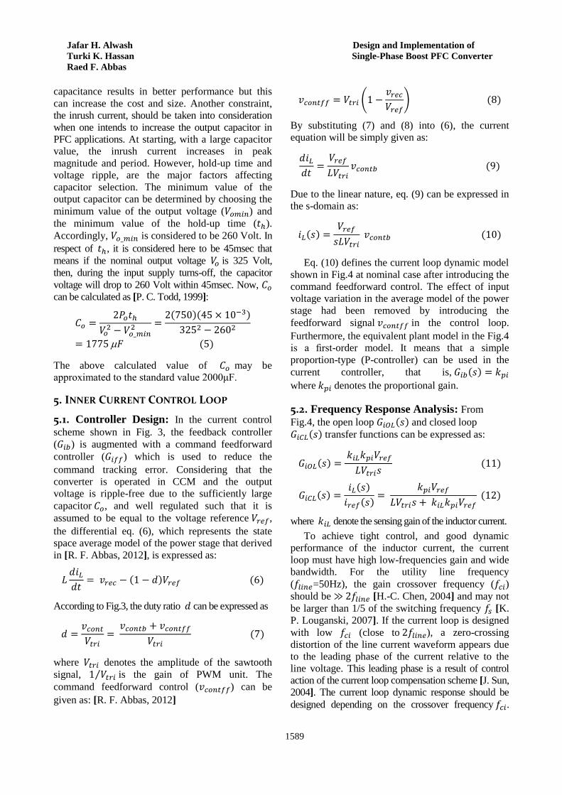
Jafar H. Alwash Design and Implementation of
Turki K. Hassan Single-Phase Boost PFC Converter
Raed F. Abbas
1589
capacitance results in better performance but this
can increase the cost and size. Another constraint,
the inrush current, should be taken into consideration
when one intends to increase the output capacitor in
PFC applications. At starting, with a large capacitor
value, the inrush current increases in peak
magnitude and period. However, hold-up time and
voltage ripple, are the major factors affecting
capacitor selection. The minimum value of the
output capacitor can be determined by choosing the
minimum value of the output voltage ( ) and
the minimum value of the hold-up time ( ).
Accordingly, is considered to be 260 Volt. In
respect of , it is considered here to be 45msec that
means if the nominal output voltage is 325 Volt,
then, during the input supply turns-off, the capacitor
voltage will drop to 260 Volt within 45msec. Now,
can be calculated as [P. C. Todd, 1999]:
The above calculated value of may be
approximated to the standard value 2000μF.
5. INNER CURRENT CONTROL LOOP
5.1. Controller Design: In the current control
scheme shown in Fig. 3, the feedback controller
( ) is augmented with a command feedforward
controller ( ) which is used to reduce the
command tracking error. Considering that the
converter is operated in CCM and the output
voltage is ripple-free due to the sufficiently large
capacitor , and well regulated such that it is
assumed to be equal to the voltage reference ,
the differential eq. (6), which represents the state
space average model of the power stage that derived
in [R. F. Abbas, 2012], is expressed as:
According to Fig.3, the duty ratio can be expressed as
where denotes the amplitude of the sawtooth
signal, ⁄ is the gain of PWM unit. The
command feedforward control ( ) can be
given as: [R. F. Abbas, 2012]
(
)
By substituting (7) and (8) into (6), the current
equation will be simply given as:
Due to the linear nature, eq. (9) can be expressed in
the s-domain as:
Eq. (10) defines the current loop dynamic model
shown in Fig.4 at nominal case after introducing the
command feedforward control. The effect of input
voltage variation in the average model of the power
stage had been removed by introducing the
feedforward signal in the control loop.
Furthermore, the equivalent plant model in the Fig.4
is a first-order model. It means that a simple
proportion-type (P-controller) can be used in the
current controller, that is,
where denotes the proportional gain.
5.2. Frequency Response Analysis: From
Fig.4, the open loop and closed loop
transfer functions can be expressed as:
where denote the sensing gain of the inductor current.
To achieve tight control, and good dynamic
performance of the inductor current, the current
loop must have high low-frequencies gain and wide
bandwidth. For the utility line frequency
( =50Hz), the gain crossover frequency ( ) should be ≪ [H.-C. Chen, 2004] and may not
be larger than 1/5 of the switching frequency [K.
P. Louganski, 2007]. If the current loop is designed
with low (close to ), a zero-crossing
distortion of the line current waveform appears due
to the leading phase of the current relative to the
line voltage. This leading phase is a result of control
action of the current loop compensation scheme [J. Sun,
2004]. The current loop dynamic response should be
designed depending on the crossover frequency .

Journal of Engineering Volume 19 December 2013 Number 12
1590
From eq. (11), the unity gain crossover frequency can
be found as:
By determining the crossover frequency, the
parameter of P-controller ( ) can be found from
eq. (13). The crossover frequency is chosen here to
be 1/6 of the switching frequency , that is . Values of and are chosen to be 3.2
and 0.1 respectively, then can be calculated as:
According to (14), is calculated to be 4.6.
6. OUTER VOLTAGE CONTROL LOOP
6.1. Controller Design: A simple proportional-
plus-integral (PI) type controller is used to control
the outer voltage loop. the dc side capacitor voltage
( ) is fed back and compared with a control
reference, and the error is compensated by the PI-
controller to produce which in turn provides the
reference current to the inner-loop through
multiplying it by a rectified sine wave signal as
shown in Fig.5. The PI controller acts upon the
error with parallel proportional and integral
responses in an attempt to drive the error to zero.
The transfer function of the PI-controller can be
expressed as:
where and are the proportional and integral
gains, respectively, is the angular frequency of
the zero in the PI controller and ⁄ .
To design the outer loop controller, it is assumed
that the inner loop is unity; the inductor current
has tracked the reference current , as illustrated
in Fig.5. Then, referring to Fig.6, the open loop
transfer function of the outer loop can be
expressed as:
The small signal control-to-output voltage transfer
function ( ), which can be used to design the
voltage loop, has been derived in [R. F. Abbas, 2012] as:
Now, substituting (15) and (17) into (16) yields:
where , , denote the scaling factors of the
rectified input voltage, output voltage, and the input
voltage feedforward respectively. denotes the form
factor (rms ⁄ average) of the full wave rectified voltage
which equal to 1.11 ( √ ⁄ ) and expressed as:
where is the rms of the input supply,
denotes the output signal of the input voltage
feedforward circuit which represents the average of
the rectified input voltage. This feedforward voltage
is essential to remove the effect of input voltage
variation by generating a rectified sine wave
signal [M. H. Rashid, 2007].
6.2. Frequency Response Analysis: To
determine the PI Parameters and the outer-
loop is compensated to satisfy the following design
requirements:
Unity gain crossover frequency ( ) is greater
than 5Hz.
Phase margin ( ) . Overshoot is less than 20%.
Settling time is below 125msec.
By using the circuit parameters in table (2), the
open loop and the closed
loop transfer function can be given as:
( )
( )
( )
Using Eqs. (20) and (21), Bode plots of the
voltage loop can be computed in matlab program. The frequency and step response of the outer loop
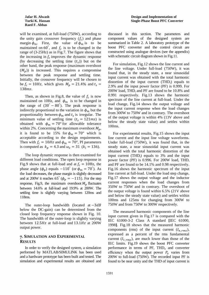
Jafar H. Alwash Design and Implementation of
Turki K. Hassan Single-Phase Boost PFC Converter
Raed F. Abbas
1591
will be examined, at full-load (750W), according to
the unity gain crossover frequency ( ) and phase
margin . First, the value of is to be
maintained on , and is to be changed in the
range of (3-25Hz) as in Fig.7. The figure shows that
the increasing in improves the dynamic response
(by decreasing the settling time ( )) but on the
other hand, the peak response (maximum overshoot
( )) is increased. This requires a compromise
between the peak response and settling time.
Initially, the crossover frequency will be chosen to
be , which gives and
.
Then, as shown in Fig.8, the value of is now
maintained on 10Hz, and is to be changed in
the range of ( ). The peak response is
indirectly proportional to the variation in but the
proportionality between and is irregular. The
minimum value of settling time ( ) is
obtained with for allowable tolerance
within 2%. Concerning the maximum overshoot
it is found to be 15% for which is
acceptable according to the design requirements.
Then with and , PI parameters
is computed as and ( ).
The loop dynamic response is then examined for
different load conditions. The open loop response in
Fig.9 shows that at full-load and at , the
phase angle ( ) equals (or ). As
the load decreases, the phase margin is slightly decreased
and at 200W it reaches ( . For the step
response, Fig.9, the maximum overshoot fluctuates
between 14.6% at full-load and 19.9% at 200W. The
settling time is slightly varying between 120ms and
118ms.
The outer-loop bandwidth (located at
below the DC-gain) can be determined from the
closed loop frequency response shown in Fig. 10.
The bandwidth of the outer-loop is slightly varying
between at full-load and at 200W
output power.
7. SIMULATION AND EXPERIMENTAL RESULTS
In order to verify the designed system, a simulation
performed by MATLAB/SIMULINK has been used
and a hardware prototype has been built and tested. The
simulation and experimental results are obtained and
discussed in this section. The parameters and
component values of the designed system are
summarized in Table 2. A laboratory prototype of the
boost PFC converter and the control circuit are
constructed using analogue devices (see the appendix)
with schematic circuit diagram shown in Fig.11.
For simulation, Fig.12 shows the line current and
the line voltage. Under full-load (750W), it was
found that, in the steady state, a near sinusoidal
input current was obtained with the total harmonic
distortion of the input current (THDi) equals to
2.9% and the input power factor (PF) is 0.999. For
200W load, THDi and PF are found to be 10.8% and
0.991 respectively. Fig.13 shows the harmonic
spectrum of the line current at full-load. Under the
load change, Fig.14 shows the output voltage and
the input current response when the load changes
from 300W to 750W and in contrary. The overshoot
of the output voltage is within 4% (13V above and
below the steady state value) and settles within
100ms.
For experimental results, Fig.15 shows the input
line current and the input line voltage waveforms.
Under full-load (750W), it was found that, in the
steady state, a near sinusoidal input current was
obtained with the total harmonic distortion of the
input current (THDi) equals to 3% and the input
power factor (PF) is 0.996. For 200W load, THDi
and PF are found to be 14.1% and 0.98 respectively.
Fig.16 shows the harmonic spectrum of the input
line current at full-load. Under the load step change,
Fig.17 shows the output voltage and the inductor
current responses when the load changes from
350W to 750W and in contrary. The overshoot of
the output voltage is found within 6.5% (21V above
and below the steady state value) and settles within
100ms and 125ms for changing from 300W to
750W and from 750W to 300W respectively.
The measured harmonic components of the line
input current given in Fig.17 is compared with the IEC 61000-3-2 Class A standard [IEC 61000,
1998]. Fig.18 shows that the measured harmonic
components (rms) of the input current ( ),
expressed as a percent of the rms fundamental
current ( ), are much lower than those of the
IEC limits. Fig.19 shows the boost PFC converter
performance in terms of PF, THDi, and converter
efficiency when the output power varies from
200W to full-load (750W). The recorded input PF is
found to be near unity and the THD of input current is

Journal of Engineering Volume 19 December 2013 Number 12
1592
complied with IEC 61000-3-2 regulation. In spite of
the hard switching operation, the single phase boost
PFC shows good performance in terms of efficiency.
The system is tested with 85V and 135V input
voltage at full-load operation. THDi and PF are
found to be 5.4% and 0.988 respectively for 85V
input voltage. For 135V, THDi and PF are found to
be 3.2% and 0.991 respectively.
8. CONCLUSION
In this paper, a single stage single switch PFC
converter has been designed to improve the power
quality to be complied with the IEC 61000-3-2
Class A limits. The power factor has been recorded
to be within 0.996-0.98 and the THDi is found to be
3%-14.1%. A current mode control at a constant
switching frequency has been used as a control
strategy for PFC converter. In the current control
scheme, the feedback controller is augmented with a
command feedforward controller which simplifies
the current controller design. The controller
parameters have been designed depending on the
frequency response analysis. A hardware prototype
has been built to verify the designed system. The
experimental results showed good agreement with
the analytical and simulated results.
REFERENCES
A. Fernandez, J. Sebastian, M. M. Hernando, P.
Villegas, and J. Garcia, "Helpful hints to select a
power-factor-correction solution for low- and
medium- power single-phase power supplies,‖ IEEE
Trans. Ind. Electron., vol. 52, no. 1, pp. 46–55, Feb.
2005.
A. Fernandez, J. Sebastian, and P. Villegas,
"Dynamic limits of a power-factor preregulator,"
IEEE Trans. Ind. Electron., vol. 52, no. 1, pp. 77–
86, Feb. 2005.
A. Prodic´, "Compensator Design and Stability
Assessment for Fast Voltage Loops of Power Factor
Correction Rectifiers," IEEE Trans. Power Electron.
vol. 22, no. 5, pp. 1719–1730, Sep. 2007.
C. K. Tse, "Circuit Theory and Design of Power
Factor Correction Power Supplies," IEEE
Distinguished Lecture 2005, Circuits and Systems.
C. Zhou and M. M. Jovanovic, "Design trade-offs in
continuous current mode controlled boost power
factor correction circuits," in Proc. High Freq.
Power Conv. Conf. HFPC’92, May 1992, pp. 209–
220.
Electromagnetic Compatibility (EMC)–Part 3:
Limits-Section2: Limits for Harmonic Current
Emissions (Equipment Input Current <16 A per-
Phase), IEC 61000-3-2, 1998.
G. Chu, C. K. Tse, S. C. Wong, and S.-C. Tan, "A
Unified Approach for the Derivation of Robust
Control for Boost PFC Converters," IEEE Trans.
Power Electron., vol. 24, no. 11, pp. 2531–2544,
Nov. 2009.
G. Spiazzi, P. Mattavelli, and L. Rossetto, "Power
factor Preregulators with improved dynamic
response," IEEE Trans. Power Electron., vol. 12,
no. 2, pp. 343–349, Mar. 1997.
H.-C. Chen, H.-Yi Li, and R.-S. Yang, "Phase
Feedforward Control for Single-Phase Boost-Type
SMR," IEEE Trans. Power Electron., vol. 24, no. 5,
pp. 1428-1432, May. 2009.
H.-C. Chen, S. H. Li, and C. M. Liaw, "Switch-
mode rectifier with digital robust ripple
compensation and current waveform controls,"
IEEE Trans. Power Electron., vol. 19, no. 2, pp.
560-566, Mar. 2004.
J. Sebastian, D. G. Lamar, M. M. Hernando, A. R.-
Alonso, and A. Fernandez, "Steady-State Analysis
and Modeling of Power Factor Correctors with
Appreciable Voltage Ripple in the Output-Voltage
Feedback Loop to Achieve Fast Transient
Response," IEEE Trans. Power Electron. vol. 24,
no. 11, pp. 2555–2566, Nov. 2009.
J. Sun, "On the zero-crossing distortion in single-
phase PFC converter," IEEE Trans. Power
Electron., vol. 19, no. 3, pp. 685–692, May 2004.
K.-M. Ho, C.-A. Yeh, and Y.-S. Lai, "Novel
Digital-Controlled Transition Current-Mode Control
and Duty Compensation Techniques for Interleaved
Power Factor Corrector," IEEE Trans. Power
Electron. vol. 25, no. 12, pp. 3085–3094, Dec. 2010.
K. P. Louganski and J. S. Lai, "Current phase lead
compensation in single-phase PFC boost converters
with a reduced switching frequency to line
Jafar H. Alwash Design and Implementation of
Turki K. Hassan Single-Phase Boost PFC Converter
Raed F. Abbas
1593
frequency ratio," IEEE Trans. Power Electron., vol.
22, no. 1, pp. 113–119, Jan. 2007.
L. H. Dixon, "Average current mode control of
switching power supplies," Unitrode, Watertown,
MA, Appl. Note U-140, 1990.
L. H. Dixon, ―High power factor switching pre-
regulator design optimization,‖ Texas Instruments,
Dallas, Unitrode Power Supply Des. Semin. Manual
SEM700, 1990.
M. H. Rashid, "Power Electronics Handbook," 2nd
ed., Academic Press, San-Diego, 2007.
O. Garcia, J. A. Cobos, R. Prieto, P. Alou, and J.
Uceda, ―Single phase power factor correction: A
survey,‖ IEEE Trans. Power Electron., vol. 18, no.
3, pp. 749–755, May 2003.
P. C. Todd, "UC3854 Controlled, Power Factor
Correction Circuit Design," Unitrode Corp.,
Merrimack, NH, Appl. Note U-134, pp. 3-269–3-
288, 1999.
P. C. Todd, "Boost Power Factor Corrector Design
with the UC3854," Unitrode Corp., Merrimack, NH,
Appl. Note U-159, 1999.
R. F. Abbas, "Single-Phase Boost Power Factor
Corrected Converter for Induction Motor Drive,"
M.Sc. Thesis, Baghdad University, Baghdad, 2012.
R. Ghosh and G. Narayanan, "Generalized
feedforward control of single-phase PWM rectifiers
using disturbance observers," IEEE Trans. Ind.
Electron., vol. 54, no. 2, pp. 984–993, Apr. 2007.
S. Wall and R. Jackson, ―Fast controller design for
single-phase power-factor-correction systems,‖
IEEE Trans. Ind. Electron., vol. 44, no. 5, pp. 654–
660, Oct. 1997.

Journal of Engineering Volume 19 December 2013 Number 12
1594
Table (1) Different techniques for voltage loop dynamic improvement
Technique description Drawback and limitation
Conventional
two-stage
converters
Second stage is connected in
cascade with the PFC converter to
provide fast response.
High cost, large size, low efficiency, and complicated
control circuit particularly in low-power applications
[ A. Fernandez, 2005]
Voltage ripple
filtering
LPF: notch, or comb filter inserted
before or after the voltage controller
Cannot eliminate the 4th and higher order harmonics in
the output voltage. For notch, or comb filter, to eliminate
the 4th harmonics, analog implementation is difficult due
to its complex structure and digital implementation
requires large memory storage.[ R. Ghosh, 2007]
Give a trade-off between improving the dynamic
response and current distortion [ A. Fernandez, 2005]
Voltage ripple
cancellation
The ripple is eliminated by
modifying the voltage reference
with a component having the same
amplitude and opposite sign of the
sensed voltage ripple.
Not easily implemented in low-cost PFCs. [ J.
Sebastian, 2009] Give a trade-off between improving the dynamic
response and current distortion. [ G. Spiazzi, 1997]
Current distortion increased during disturbance, so
that, additional circuit is required which complicate
the control circuit
Regulation
band and
dead-zone
controllers
Depending on the amplitude of the
voltage-loop error signal, bandwidth of
voltage loop is kept low at steady state to
obtain a sinusoidal input current. During
transients, it is increased to have a good
dynamic response.
For small errors, approximately equal to the ripple
magnitude, the loop is either slow or completely insensitive
to voltage variations and hence the system suffers from
regulation problem [A. Prodic , 2007].
Have limit cycle oscillations at light loads [R. Ghosh,
2007]
𝑣𝑐𝑜𝑛𝑡
𝑣𝑜
𝑉𝑟𝑒𝑓
𝑖𝐿
𝑖𝑟𝑒𝑓
𝑑
𝑣𝑟𝑒𝑐
Voltage
Controller
𝐺𝑐𝑣
Current
Controller
𝐺𝑐𝑖
𝑣𝑡𝑟𝑖
𝑣𝑖𝐿
𝑣𝑒𝑟𝑟
PWM Fig.2 Control scheme of the converter
𝑖𝑠 𝐼𝑜 𝑖𝑜
𝑣𝑠
PFC Control Circuit
𝑣𝑟𝑒𝑐 𝑣𝑜
𝑖𝐿
Boost DC-DC Converter Diode Bridge
𝐶𝑜
Fig.1 Block diagram of boost PFC converter
Load
𝑅
𝑣𝑐𝑜𝑛𝑡
𝑉𝑟𝑒𝑓 𝐺𝑖𝑓𝑓
𝑣𝑐𝑜𝑛𝑡
𝑖𝐿
𝑖𝑟𝑒𝑓
𝑣𝑐𝑜𝑛𝑡𝑓𝑓
𝑑
𝑣𝑟𝑒𝑐
𝐺𝑖𝑏
𝑣𝑡𝑟𝑖
𝑣𝑐𝑜𝑛𝑡𝑏
PWM
Boost
Converter
𝑖𝐿
𝑉𝑡𝑟𝑖 𝑑
𝐺𝑐𝑖
Fig.3 Current control scheme
𝑖𝐿
𝑉𝑟𝑒𝑓
𝑉𝑡𝑟𝑖
𝑠𝐿 𝑘𝑝𝑖
𝑣𝑐𝑜𝑛𝑡𝑏 𝑖𝑟𝑒𝑓
Current Loop Model
Fig.4 Equivalent current-loop control
𝑘𝑖𝐿
𝐺𝑖𝑏

Jafar H. Alwash Design and Implementation of
Turki K. Hassan Single-Phase Boost PFC Converter
Raed F. Abbas
1595
𝑉𝑓𝑓
𝑣𝑟𝑒𝑐 𝑣𝑜
1
𝑣𝑜 𝑉𝑟𝑒𝑓
𝑖𝐿 𝑖𝑟𝑒𝑓
s t
𝐺𝑐𝑣 𝑠 𝑉𝑟𝑚𝑠
𝑉𝑜
𝑅
𝑅𝐶𝑜𝑠
𝑣𝑖𝐿
Closed
Current Loop Power Stage
Fig.5 Voltage control scheme
𝑣𝑒𝑟𝑟
Divider
𝑘𝑣𝑜
𝑣𝑒𝑟𝑟
𝑉𝑟𝑒𝑓
𝑖𝑟𝑒𝑓 𝑖𝐿
𝐺𝑐𝑣 𝑠 𝐺𝑝𝑣 𝑠
𝑣𝑜 𝑣𝑖𝐿
Fig.6 Block diagram of the voltage loop
𝑓𝑐
𝑓𝑐
Fig.7 Outer loop frequency response at full-load, 𝜙𝑚 for
different values of 𝑓𝑐 ; upper: open loop, lower: step response
80 70
60 45 𝜙𝑚=30
Fig.8 Outer loop frequency response at full-load, 𝑓𝑐=10Hz for
different values of 𝜙𝑚 ; upper: open loop, lower: step response
𝜙𝑚 𝑡𝑠 𝑚𝑠 𝑀𝑝
𝜙𝑚 𝑡𝑠 𝑚𝑠 𝑀𝑝
𝜙𝑚 𝑡𝑠 𝑚𝑠 𝑀𝑝
𝜙𝑚 𝑡𝑠 𝑚𝑠 𝑀𝑝
𝜙𝑚 𝑡𝑠 𝑚𝑠 𝑀𝑝
Fig.9 Frequency response of the outer loop, with 𝑘𝑝
and 𝑘𝑖 for different load conditions; upper: open loop,
middle: step response shows ts, lower: step response shows Mp
𝑓𝑐 𝐻𝑧 𝑡𝑠 𝑚𝑠 𝑀𝑝
𝑓𝑐 𝐻𝑧 𝑡𝑠 𝑚𝑠 𝑀𝑝
𝑓𝑐 𝐻𝑧 𝑡𝑠 𝑚𝑠 𝑀𝑝 𝑓𝑐 𝐻𝑧 𝑡𝑠 𝑚𝑠 𝑀𝑝
𝑓𝑐 𝐻𝑧 𝑡𝑠 𝑚𝑠 𝑀𝑝 𝑓𝑐 𝐻𝑧 𝑡𝑠 𝑚𝑠 𝑀𝑝
Fig.10 Outer loop frequency response with 𝑘𝑝 and 𝑘𝑖
for different load conditions; upper: closed loop, lower: a magnified
section of the magnitude in (upper) shows the loop bandwidth
Fig.12 Steady state of input current and input voltage
waveforms; upper: at 750W, lower: at 200W
0.12 0.13 0.14 0.15 0.16 0.17 0.18 0.19 0.2
0.12 0.13 0.14 0.15 0.16 0.17 0.18 0.19 0.2
1A
2A
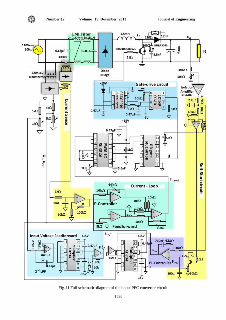
Journal of Engineering Volume 19 December 2013 Number 12
1596
Fig.11 Full schematic diagram of the boost PFC converter circuit
0.47 F
0.47 F
𝒌𝒗𝒊 𝒗
𝒓𝒆𝒄
𝒅
5k
Input Voltage Feedforward
𝟐𝟕𝒌𝛀
𝟐𝟎𝒌𝛀
2nd
LPF
0.47 F
1 F
0.47 F
0.4
7
F
10k
90k
𝑽𝒇𝒇𝟐
-15V
+15V
-15V
2M
+15V
14
13
12
11
10
9
8
1
2
3
4
5
6
7
Mu
ltiplie
r A
D7
34
14
13
12
11
10
9
8
1
2
3
4
5
6
7
Mu
ltiplie
r A
D7
34
𝒊𝒓𝒆𝒇
Soft-Start circu
it
10k 10k
10k
10k
10k
3.2V
5k
100k 10k
50nF
1k
𝟏𝟎𝐤
𝟒𝟔𝐤 Current - Loop
P-Controller
Feedforward
𝒗𝒄𝒐𝒏𝒕
PI-Controller
50k
10 +15V
100 F
𝑽𝒓𝒆𝒇
𝟏𝟎𝒌
730nF 𝟒𝟑𝒌
10
k
5k 5.6nF
5k
0.47 F
18
17
16
15
14
13
12
11
10
1
2
3
4
5
6
7
8
9
PW
M-IC
S
G3
52
6
1
2
3
4
5
6
7
OR
-ga
te
MC
14
07
5B
14
13
12
11
10
9
8
+15V
5k 5k
1k
1k
220/16v Transformer
Cu
rrent Sen
se
circuit
10
Diode Bridge
SKM100GB102D
51 5.5nF
100
120 2.2nF
RURP3060 20
00
F
𝒗𝒐 𝒊𝑳 1.5mH 218 H 20.27mH
3:1000 C.T
0.68 F 0.68 F
110Vrms 50Hz
EMI Filter
51
-5V
10k
1k
1
2
3
4
8
7
6
5
OP
TO
6
N1
37
1
2
3
4
Ga
te-D
riv
er
MC
33
15
3
+15V
0.47 F 0.47 F
Gate-drive circuit
R
680k
50k
Isolation Amplifier 3656HG
2.2 F
66k
68
0k
1
0k
4
.7k
𝒗𝒊𝑳
8
7
6
5

Jafar H. Alwash Design and Implementation of
Turki K. Hassan Single-Phase Boost PFC Converter
Raed F. Abbas
1597
Fig.13 Harmonic spectrum of the line current (rms) at full-load
0.2 0.3 0.4 0.5 0.6 0.7 0.8 0.9 1 1.1
Fig.14 Waveforms of output voltage 𝑣𝑜 and input current 𝑖𝑠 when the load steps from 300W to 750W (upper: 𝑣𝑜 50V/div;
lower: 𝑖𝑠 50 A/div).
Fig.16 Harmonic spectrum of the measured input line current
(rms) at full-load
Frequency (125Hz/div)
1.5A
Time (50msec/div)
Fundamental
Fig.15 Steady state of the measured input current and input
voltage waveforms; upper: at 750W, lower: at 200W
𝑣𝑠 (50V/div)
𝑖𝑠 (10A/div)
𝑣𝑠 (50V/div)
𝑖𝑠 (5A/div)
Time (5msec/div)
Fig.17 Waveforms of output voltage 𝑣𝑜 and inductor current 𝑖𝐿
under the load change; upper: from 350W to 750W, lower:
from 750W to 350W
𝑖𝐿 (5A/div)
𝑖𝐿 (5A/div)
𝑣𝑜 (Scaled) 5V
𝑣𝑜 (Scaled) 5V
Time (25msec/div)
Fig.18 Measured harmonic content of the input current at full-
load versus IEC 61000-3-2 Class A limits
Fig.19 PFC converter performance with respect to the output
power; upper: THDi vs. Po, lower: efficiency and PF vs. Po
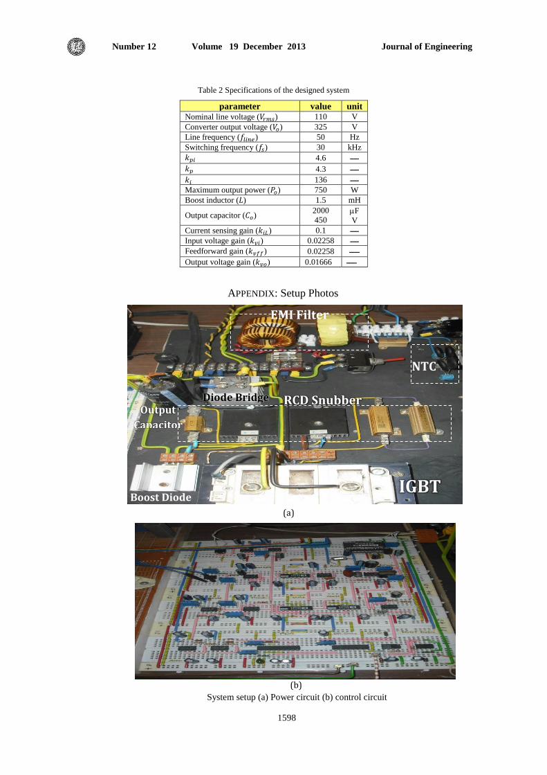
Journal of Engineering Volume 19 December 2013 Number 12
1598
parameter value unit Nominal line voltage ( ) 110 V
Converter output voltage ( ) 325 V
Line frequency ( ) 50 Hz
Switching frequency ( ) 30 kHz
ـــــ 4.6
ـــــ 4.3
ـــــ 136
Maximum output power ( ) 750 W
Boost inductor ( ) 1.5 mH
Output capacitor ( ) 2000
450 F
V
Current sensing gain ( ) 0.1 ـــــ
Input voltage gain ( ) 0.02258 ـــــ
Feedforward gain ( ) 0.02258 ــــــ
Output voltage gain ( ) 0.01666 ــــــ
IGBT
EMI Filter
RCD Snubber
NTC
Boost Diode
Diode Bridge Output
Capacitor
(a)
APPENDIX: Setup Photos
Table 2 Specifications of the designed system
(b)
System setup (a) Power circuit (b) control circuit
![lyceumpasspapers.files.wordpress.com...2013/05/08 · a bladder with a cavity. leaves with two halves that interlock. a hallow tube (pitcher). [Total = 2 x 10 = 20 marks] Part If](https://img.dokumen.tips/doc/110x75/5eaa02057579260dd0263dcd/-20130508-a-bladder-with-a-cavity-leaves-with-two-halves-that-interlock.jpg)
![KOLON BROCHURE V1.4 ENG · Position[rnm] KOLON Membrane Process KOLON membrane products compose of reinforced hallow fiber membrane made with PVDF (Polyvinylidene Fluoride) that has](https://img.dokumen.tips/doc/110x75/601db1adaad2eb184a2efc4d/kolon-brochure-v14-eng-positionrnm-kolon-membrane-process-kolon-membrane-products.jpg)