Embed Size (px)
Citation preview

Proceedings of the Ninth Pacific Conference on Earthquake Engineering Building an Earthquake-Resilient Society
14-16 April, 2011, Auckland, New Zealand
Paper 062
Experimental investigation on the in-plane behaviour of non-ductile RC walls
A.S. Gebreyohaness, G.C. Clifton & J.W. Butterworth
Department of Civil & Environmental Engineering. The University of Auckland, Auckland, New Zealand.
ABSTRACT: Past earthquakes have demonstrated that buildings with non-ductile RC components as their primary lateral load resisting system pose a significant seismic risk. Assessment and retrofit of such buildings entails a careful evaluation of the as-built performance of the lateral load resisting components. A series of quasi-static cyclic tests on reconstructed RC wall specimens of an existing building are being undertaken at the University of Auckland, to determine the seismic performance of non-ductile walls in the framework of a research project addressing the seismic assessment and retrofit of existing buildings in New Zealand. Wall thickness, aspect ratio, level of axial load, and the effects of splices and boundary reinforcement are amongst the important parameters being investigated.
The test setup, loading regime and details of the first two experimental tests are presented herein. The lateral load capacity of the lightly reinforced non-ductile RC walls investigated is found to be dictated by the flexural strength at their base. However, due to the plain round bars used, the walls didn’t develop distributed flexural cracks but rather exhibited a predominantly rocking response about a single crack located at the foundation-wall interface. In addition, they had limited ductility capacity, which is inferred to be dependent on the level of axial load. The current NZSEE guideline underestimated the contribution of concrete to the shear strength of the walls and predicted the wrong mode of failure for one of the walls.
1 INTRODUCTION
The existing building stock incorporating non-ductile walls comprises a considerable portion of vulnerable structures that pose a significant seismic risk in some seismically active parts of the world (Orakcal et al., 2009). These types of walls are encountered in a group of multi-storey buildings in New Zealand built during the early 20th century (e.g. the Hope-Gibbons, a dual RC wall-steel frame building in Wellington). Similar to these heritage buildings, many of the pre-1975 multi-storey buildings aren’t purely frame or wall structures; and possibly contain these types of walls.
Although buildings containing non-ductile RC walls performed relatively well compared to unreinforced masonry buildings in the 2010 Darfield earthquake (Kam et al., 2010), significant damage to RC walls was reported in the larger magnitude and longer duration earthquakes of Chile, 2010 (EERI, 2010) and Kocaeli, Turkey, 1999 (Sezen et al., 2003) and more severe damages were observed in the 1985 Chile earthquake (Wood et al., 1987).
Experimental and numerical studies on the behaviours of these types of walls are being undertaken at the University of Auckland based on the non-ductile walls of the Hope-Gibbons building. This dual wall-frame building was built in 1928 prior to the introduction of seismic resistant design requirements in the New Zealand building code in 1935. The original structural drawings and results of strength tests conducted on concrete cores extracted from this building are available. The walls in this building are lightly reinforced with plain round bars. Although the thicknesses of the walls in the building range from 150 mm to 305 mm, a single layer of reinforcement is provided to all wall types at 305 mm centres at the mid-thickness plane of the walls in both the horizontal and vertical directions. The walls are provided around the building’s perimeter and comprise one of its lateral load resisting systems.
2
They limit the lateral displacement capacity of the building and have been identified through nonlinear inelastic time history (NITH) analyses as being critical to the seismic performance of the building (Gebreyohaness et al., 2010).
Limited research (See Section 2 and 3) has been performed in the past on the seismic performance of non-ductile walls which are lightly reinforced with a single layer of plain round bars. Thus, detailed investigation of their behaviour is necessary in order to contribute to a more realistic assessment of the probable as-built performance of buildings containing these walls and their effective retrofitting.
2 CHARACTERISTICS OF LIGHTLY REINFORCED NON-DUCTILE WALLS
Non-ductile RC walls lack reinforcement to contain the concrete in the event of damage and have relatively limited capacity to dissipate seismic energy before they fail completely. The reinforcing bars in these walls have insufficient lap lengths and lack proper end anchorages. In addition, the bars are spliced in potential plastic hinge regions and lack lateral support to prevent reinforcement buckling. These walls can also suffer instability arising from inadequate lateral restraint provided by the floor diaphragms. Furthermore, due to the pattern of wall openings not being developed with earthquake response in mind, they often generate torsional and vertical irregularity in a building.
In the absence of boundary frame elements, lightly reinforced walls can suffer a predominantly flexural mode of failure, due to lack of adequate vertical reinforcement (Greifenhagen and Lestuzzi, 2005, Ireland et al., 2007), although walls of this kind may not achieve a desirable level of ductility. The contribution of concrete to the shear strength of RC members calculated using provisions of the NZSS 95 (NZ Standards Institute, 1935), is smaller than what would be calculated using current code provisions (Brunsdon, 1984). Consequently, RC walls built using this code are generally expected to resist the flexural overstrength actions and exhibit a ductile flexural mode of failure; however, this possibility can be significantly influenced by the deficiencies presented above. The current experimental investigations are designed to reveal the extent of influence of these deficiencies.
3 EXPERIMENTAL PROGRAM
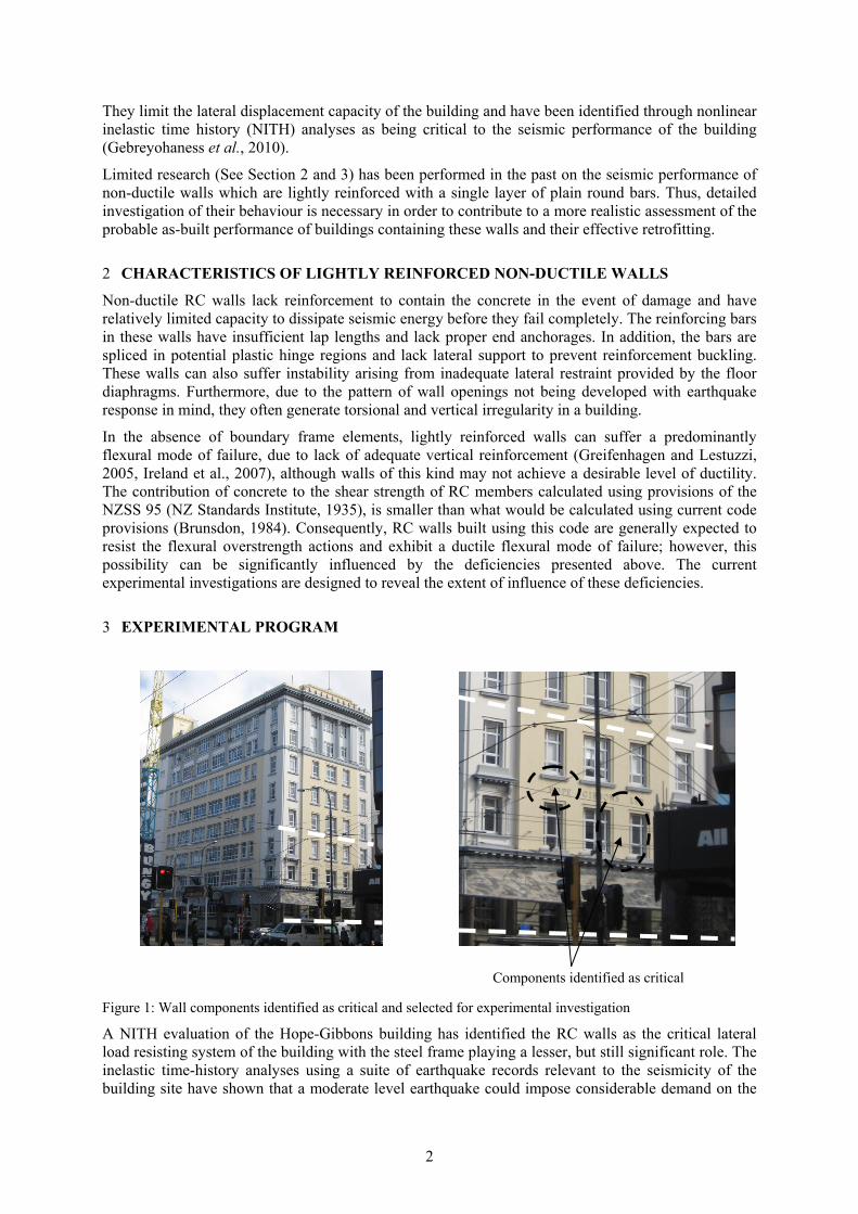
Figure 1: Wall components identified as critical and selected for experimental investigation
A NITH evaluation of the Hope-Gibbons building has identified the RC walls as the critical lateral load resisting system of the building with the steel frame playing a lesser, but still significant role. The inelastic time-history analyses using a suite of earthquake records relevant to the seismicity of the building site have shown that a moderate level earthquake could impose considerable demand on the
Components identified as critical

3
wall components located at the north-eastern corner of the building at the bottom three levels above the basement level (Gebreyohaness et al., 2010).
The experimental investigations conducted on RC walls based on relatively old detailing techniques either used deformed bars, e.g. Greifenhagen and Lestuzzi (2005) and Orakcal et al (2009); or were doubly reinforced, e.g. Greifenhagen and Lestuzzi (2005) and Ireland et al.(2007). Very few investigated the effect of splices on the performance of the walls, and none examined the effect of the very short splice length of 12db used in buildings like the Hope-Gibbons (db - diameter of reinforcing bar). Thus, a series of experimental investigations are being undertaken to determine the performance of these walls. The actual geometries and reinforcement arrangement of piers and spandrels located at the northern perimeter of the building are being used in the experimental investigations (Refer to Figure 1). Wall thickness, level of axial load, and the effects of splices and boundary reinforcement are the important parameters being investigated. The first two experimental investigations are discussed herein.
3.1 Description of specimen
The properties of the first two test specimens are summarized in Table 1 and Figure 2. In Table 1 Lw represents length of wall specimen, H is height of wall specimen, fc
’ is compressive strength of concrete, fy
is yield strength of reinforcing steel, and N/Ag fc’ denotes ratio of applied load to specimen
axial force capacity.
Table 1. Properties of the test specimens
Specimen Lw H t f'c fy , fyt N/Agf'c Reinforcement
(mm) (mm) (mm) (MPa) (MPa) (%) (Vertical/Horizontal)
WPS1 1300 1750 150 18.4 530 5 ∅10mm c/c 305mm
WPS2 1300 1750 230 20.9 300 5 ∅10mm c/c 305mm
The wall piers were tested in an upright position as a cantilever. This testing arrangement is representative of walls in low-rise buildings; it is also mainly intended to understand the response of non-ductile walls under lateral loading. In the upcoming tests the wall components will be tested in a double curvature loading condition, which is a more realistic representation of walls in multi-storey buildings. The influence of the frame elements was not the subject of this study. In the tests presented herein, the flexural bars weren’t spliced and no boundary reinforcement was provided.
Figure 2: Experimental specimen WPS2
1500 mm 600 mm
800 mm2000 mm
Ø10mmc/c 305mm
1600 mm
300 mm
400 mm
1300 mm
230 mm

4
3.2 Experimental setup
The wall components were built on RC foundation blocks which were anchored to the strong floor, to provide a fixed condition at the base. The foundation blocks also provided anchorage to the flexural reinforcements of the specimens. An RC block was constructed on the top of the specimens to maintain continuity of reinforcement and to facilitate a smooth transfer of gravity and lateral loads. Out-of-plane movement of the specimens was prevented using channel sections provided on both sides and parallel to the loading beam.
The gravity loads were applied using high strength bars positioned parallel to the centreline and down the sides of the specimens and anchored to the strong floor. To prevent the high strength bars from contributing to the stiffness/strength of the wall, a combination of rollers at the top of the loading beams and coil springs underneath the strong floor was employed (Refer to Figure 3).
Figure 3: Test setup
3.3 Loading regime
Incrementing sets of three complete displacement-controlled reversed cycles as shown in Fig. 4 were applied at the top of the specimens using a hydraulic jack as shown in Figure 3.
Figure 4: Applied loading regime
High strengthbars
RollersCross beam
Out-of-planemovementrestricting channels
Coil springs
Load Cell
Strong wall
Strong floor
Loading beam
Wall specimen
Foundation block
Hydraulic jack
-60
-40
-20
0
20
40
60
-3.50%
-2.50%
-1.50%
-0.50%
0.50%
1.50%
2.50%
3.50%
0 20 40 60
Dis
pla
cem
ent,
mm
Dri
ft
Cycles

5
3.4 Instrumentation
Load cells were employed to measure the magnitude of lateral and axial loads applied on the specimens. The horizontal displacement at the top and the lateral displacement profiles of the specimens were determined using LVDTs. Portal gauges were used to measure rocking, flexural and shear deformations. Any possible relative sliding displacements that could have occurred during the tests at the strong floor - foundation block, foundation block– specimen, and specimen-loading beam interfaces were also monitored. Eight strain gauges per specimen were attached to the horizontal and vertical reinforcing bars. The strain gauges facilitated determination of the strain profile over the length and height of the specimens.
3.5 Test observations and results
Both specimens exhibited a hysteretic behaviour similar to the one presented in Figure 5 resulting in a limited amount of energy dissipation, mainly due to bar slip and lack of confinement of the compression zone. As expected the lateral load capacity of the specimens were dictated by yielding of the flexural bars at the base. Due to the plain round bars used, there was no development of distributed flexural cracks.
Figure 5: Lateral force vs top displacement of WPS2
The first hairline crack formed at a drift of 0.25% in both experimental tests; and this crack had extended across the full length of the wall at a drift of 0.35% and 0.50% for the thinner and the thicker wall respectively. The flexural reinforcement of the thinner walls ruptured in successive 1.4% drift cycles, while flexural reinforcement of the thicker wall started to rupture at a 0.75% drift. After rupturing of the vertical bars, the walls behaviour resembled a controlled rocking response, with poor energy dissipation characteristics due to lack of any dissipative mechanism except sliding at the wall- foundation interface, but with good retention of strength, especially for test 2. Despite the effort to keep the variation of the vertical load to a minimum, there was an increase in vertical load by up to 12% at the maximum strengths.
The wall specimens exhibited a predominantly rocking response about a single crack located at their bases (See Figure 6). Apart from crushing and spalling at the corners, which were unsymmetrical, and the single crack which extended across the full length of the wall, there were no other visible deformations. This is illustrated in the left hand picture of Figure 6 and is distinctly different from the
-70 -35 0 35 70
-200
-150
-100
-50
0
50
100
150
200
-4.00% -2.00% 0.00% 2.00% 4.00%
Displacement, mm
Lat
eral
For
ce, k
N
Drift, %
6
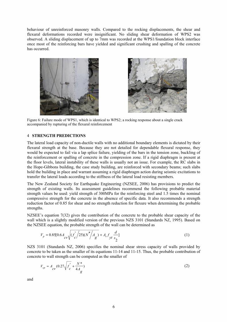
behaviour of unreinforced masonry walls. Compared to the rocking displacements, the shear and flexural deformations recorded were insignificant. No sliding shear deformation of WPS2 was observed. A sliding displacement of up to 7mm was recorded at the WPS1/foundation block interface once most of the reinforcing bars have yielded and significant crushing and spalling of the concrete has occurred.
Figure 6: Failure mode of WPS1, which is identical to WPS2; a rocking response about a single crack accompanied by rupturing of the flexural reinforcement
4 STRENGTH PREDICTIONS
The lateral load capacity of non-ductile walls with no additional boundary elements is dictated by their flexural strength at the base. Because they are not detailed for dependable flexural response, they would be expected to fail via a lap splice failure, yielding of the bars in the tension zone, buckling of the reinforcement or spalling of concrete in the compression zone. If a rigid diaphragm is present at the floor levels, lateral instability of these walls is usually not an issue. For example, the RC slabs in the Hope-Gibbons building, the case study building, are reinforced with secondary beams; such slabs hold the building in place and warrant assuming a rigid diaphragm action during seismic excitations to transfer the lateral loads according to the stiffness of the lateral load resisting members.
The New Zealand Society for Earthquake Engineering (NZSEE, 2006) has provisions to predict the strength of existing walls. Its assessment guidelines recommend the following probable material strength values be used: yield strength of 300MPa for the reinforcing steel and 1.5 times the nominal compressive strength for the concrete in the absence of specific data. It also recommends a strength reduction factor of 0.85 for shear and no strength reduction for flexure when determining the probable strengths.
NZSEE’s equation 7(32) gives the contribution of the concrete to the probable shear capacity of the wall which is a slightly modified version of the previous NZS 3101 (Standards NZ, 1995). Based on the NZSEE equation, the probable strength of the wall can be determined as
]
2
)*)(25'(6.0[85.0s
dyt
fAg
ANc
fcv
AV vp (1)
NZS 3101 (Standards NZ, 2006) specifies the nominal shear stress capacity of walls provided by concrete to be taken as the smaller of its equations 11-14 and 11-15. Thus, the probable contribution of concrete to wall strength can be computed as the smaller of
)4
*'27.0(
gA
Nc
fcv
AVcp (2)
and
7
)
2*
*
*2.0'1.0
'05.0(
wL
V
M
gA
Nc
fw
L
cf
cvAVcp
(3)
but this contribution is limited to (equations 11-28):
)4
*'27.0(g
A
Nc
fcv
AVcp (4)
where λ is 0.25 for ductile plastic regions and 0.5 for limited ductile plastic regions.
The contribution of the horizontal shear reinforcement to the strength of the wall is computed from equation 11-18 of NZS 3101 (2006).
2s
dyt
fAvspV (5)
The total shear capacity is limited by equation 11-29. The probable shear-friction strength of walls across a sliding plane perpendicular to the shear-friction reinforcement can be determined based on equation 7-13 of NZS 3101 (2006) as follows:
*)(, Ny
fAvfSFpV (6)
The shear capacity is also limited to the smaller of 0.2 fc’ Acv and 8 Acv, a value corresponding to a
diagonal compression failure. Unlike other codes such as the ACI 318-05 (ACI Committee 318, 2005) neither provision recognizes an increase in the shear strength of walls with high shear-to-moment ratios directly.
The flexural strengths can be determined following standard section analysis procedures as per section 7.4.2 of NZSEE (2006) and section 7.4 of NZS 3101 (2006). In the strength predictions the variation of the axial force at the maximum strengths recorded during the experimental tests and the self-weight of the cross and loading beams are considered. The results of the experiments and the strength predictions are summarized in Table 2.
Table 2. Comparison of predicted wall strengths and test results
NZSEE(2006) NZS 3101 (2006) Experiment
Specimen Vp ,kN VFlex ,kN Vp ,kN Vp,SF ,kN VFlex ,kN VTest,kN
WPS1 184 151 259 611 151 162
WPS2 165 167 258 638 167 174
5 CONCLUSION
The paper presented the first two experimental investigations conducted on reconstructed wall specimens of an existing building. The walls are representative of some pre-1975 RC wall constructions in New Zealand. The reinforcing bars in the first two walls were not spliced and no boundary reinforcement was provided.
The experimental investigation revealed that the lateral load capacity of lightly reinforced non-ductile RC walls reinforced with plain round bars and with no additional boundary elements is dictated by yielding of the flexural bars of the walls at their base. Due to usage of plain round bars and less flexural reinforcement than required by current standards, these walls do not develop distributed flexural cracks. They exhibit a rocking response and have an inferior energy dissipation capacity compared to modern walls. However, it is worth noting that a quasi-static testing doesn’t capture the
8
rather modest energy dissipation associated with rocking impacts that could be experienced by such walls during actual seismic excitations.
Assessments of the non-ductile walls using the current code provisions predicted the strengths of both walls with reasonable accuracy, while the NZSEE recommendations underestimated the shear strengths and predicted the wrong mode of failure for one of the walls.
Table 3. List of Symbols
Symbol Description Unit Symbol Description Unit Acv shear area mm2 M* design moment N mm Ag gross area of concrete section mm2 N* design axial load N
Av area of shear reinforcing bar mm2 S2
centre-to-centre spacing of shear reinforcement
mm
Avf
area of shear friction reinforcement
mm2 V* design shear force N
d
effective depth, can be taken as 0.8 times Lw
mm Vcp
probable shear strength provided by concrete
N
fc’
specified compressive strength of concrete
MPa VFlex
probable wall strength due to flexure
N
fyt
yield strength of shear reinforcement
MPa Vp,SF probable shear-friction strength N
fy yield strength of reinforcement MPa Vp probable wall shear strength N
Lw horizontal length of wall mm Vsp
probable shear strength provided by reinforcement
N
μ
coefficient of friction, 1.4 for normal weight concrete
-
ACKNOWLEDGEMENT
The authors would like to gratefully acknowledge the financial support provided to this research by the New Zealand Foundation for Research, Science and Technology (FRST).
REFERENCES
ACI COMMITTEE 318 2005. Building code requirements for structurak concrete and commentary (ACI 318M-05). Farmington Hills, MI, USA.
BRUNSDON, D. R. 1984. Seismic performance characteristics of buildings constructed between 1936 and 1975. Master's thesis, University of Canterbury.Christchurch, New Zealand
EERI 2010. EERI Special Earthquake Report: The Mw 8.8 chile earthquake of February 27, 2010.
GEBREYOHANESS, A. S., et al. 2010. Assessment of soil-foundation-structure interaction effects on the seismic performance of an old dual wall-frame building. 14th ECEE Conference, August 30 - September 4. Ohrid, Macedonia.
GREIFENHAGEN, C. & LESTUZZI, P. 2005. Static cyclic tests on lightly reinforced concrete shear walls. Engineering Structures, 27(11): 1703-1712.
IRELAND, M., et al. 2007. Experimental Investigations of a Selective Weakening Approach for the Seismic Retrofit of RC Structural Walls. NZSEE Conference, March 30 - April 1. Palmerston North, New Zealand.
KAM, W. Y., et al. 2010. Seismic Performance of Reinforced Concrete Buildings in the 2010 Darfield (Canterbury) Earthquake. Bulletin of the New Zealand Society for Earthquake Engineering, 43(4): 340-350.
NZ STANDARDS INSTITUTE 1935. NZSS 95: New Zealand Standard Model Building By-Law, Sections I to X. NZ Standards Institute, Wellington, New Zealand.
NZSEE 2006. Assessment and Improvement of the Structural Performance of Buildings in

9
Earthquakes: Recommendations of a NZSEE Study Group on Earthquake Risk Buildings. Wellington, NZ.
ORAKCAL, K., et al. 2009. Shear strength of lightly reinforced wall piers and spandrels. ACI Structural Journal, 106(4): 455-465.
SEZEN, H., et al. 2003. Performance of reinforced concrete buildings during the August 17, 1999 Kocaeli, Turkey earthquake, and seismic design and construction practise in Turkey. Engineering Structures, 25(1): 103-114.
STANDARDS NZ 1995. NZS 3101:1995 Concrete Structures Standard. Standards New Zealand, Wellington, New Zealand.
STANDARDS NZ 2006. NZS 3101:2006 Concrete Structures Standard: Part 1 – The Design of Concrete Structures. Standards New Zealand, Wellington, New Zealand.
WOOD, S. L., et al. 1987. 1985 Chile earthquake - observations on earthquake-resistant construction in vina del mar.