Embed Size (px)
Citation preview
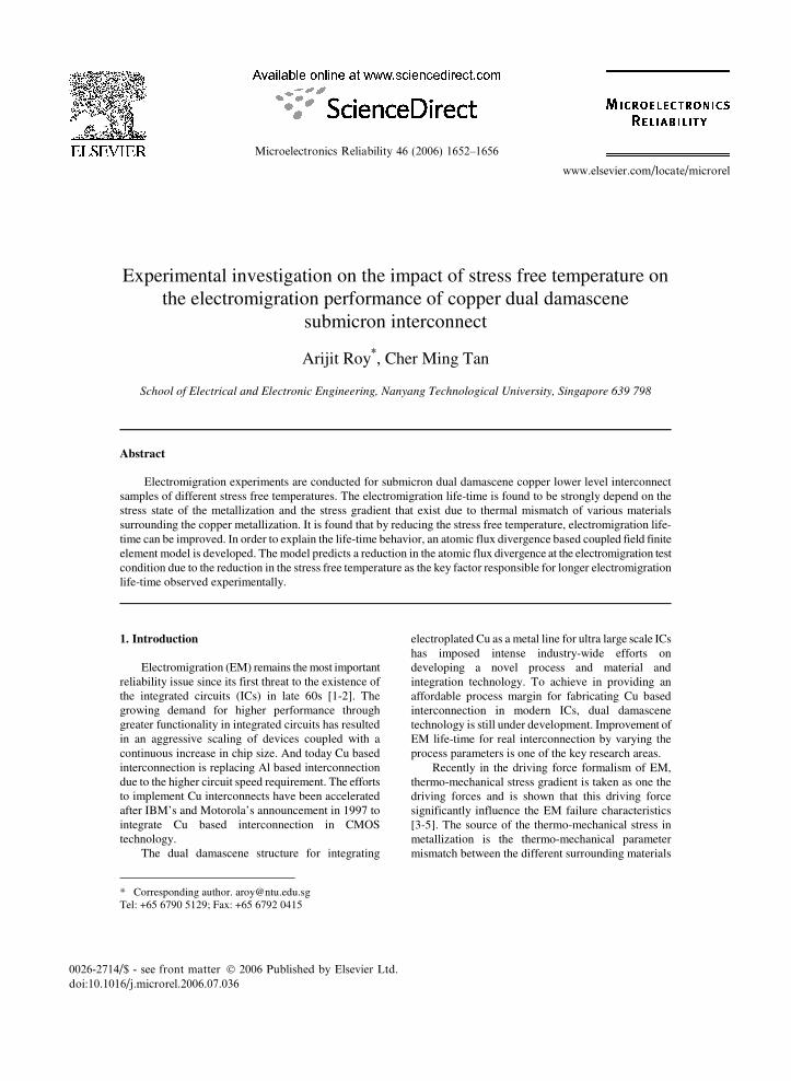
0026-2714/$ - see front matter 2006 Published by Elsevier Ltd.doi:10.1016/j.microrel.2006.07.036
Microelectronics Reliability 46 (2006) 1652–1656
www.elsevier.com/locate/microrel
Experimental investigation on the impact of stress free temperature on the electromigration performance of copper dual damascene
submicron interconnect Arijit Roy*, Cher Ming Tan School of Electrical and Electronic Engineering, Nanyang Technological University, Singapore 639 798 Abstract Electromigration experiments are conducted for submicron dual damascene copper lower level interconnect samples of different stress free temperatures. The electromigration life-time is found to be strongly depend on the stress state of the metallization and the stress gradient that exist due to thermal mismatch of various materials surrounding the copper metallization. It is found that by reducing the stress free temperature, electromigration life-time can be improved. In order to explain the life-time behavior, an atomic flux divergence based coupled field finite element model is developed. The model predicts a reduction in the atomic flux divergence at the electromigration test condition due to the reduction in the stress free temperature as the key factor responsible for longer electromigration life-time observed experimentally.
* Corresponding author. [email protected] Tel: +65 6790 5129; Fax: +65 6792 0415
1. Introduction
Electromigration (EM) remains the most important reliability issue since its first threat to the existence of the integrated circuits (ICs) in late 60s [1-2]. The growing demand for higher performance through greater functionality in integrated circuits has resulted in an aggressive scaling of devices coupled with a continuous increase in chip size. And today Cu based interconnection is replacing Al based interconnection due to the higher circuit speed requirement. The efforts to implement Cu interconnects have been accelerated after IBM’s and Motorola’s announcement in 1997 to integrate Cu based interconnection in CMOS technology.
The dual damascene structure for integrating
electroplated Cu as a metal line for ultra large scale ICs has imposed intense industry-wide efforts on developing a novel process and material and integration technology. To achieve in providing an affordable process margin for fabricating Cu based interconnection in modern ICs, dual damascene technology is still under development. Improvement of EM life-time for real interconnection by varying the process parameters is one of the key research areas.
Recently in the driving force formalism of EM, thermo-mechanical stress gradient is taken as one the driving forces and is shown that this driving force significantly influence the EM failure characteristics [3-5]. The source of the thermo-mechanical stress in metallization is the thermo-mechanical parameter mismatch between the different surrounding materials

A. Roy, C.M. Tan / Microelectronics Reliability 46 (2006) 1652–1656 1653
with the core metallization material. The amount of stress and corresponding stress gradient depends on the processing history and on EM test condition. The stress free temperature (SFT) is the temperature at which the stress in structure becomes zero. For standard dual damascene process, the SFT of copper interconnects is reported to be in the range of 350 to 400°C [6-7], depending on the cap layer process temperature or final annealing temperature. Thus significant amount of tensile stress exists in the core metallization at accelerated EM test condition (typical EM test temperature ~300˚C). This stress state generates stress gradient in the interconnect which in turn act as driving force resulting atomic flux divergence (AFD), that causes failure in the metallization. Roy et al. [8] anticipated that by reducing the SFT, stress and stress gradient that exists at EM test condition in the metallization can be reduced which in turn decrease the corresponding AFD.
A simple relation between failure time (tf) and AFD ( J•∇ ) can be found as follows. Lets N be the number of ions accumulated in a small interconnect segment of length l for a time period of t due to the presence of the flux divergence, then for an infinitesimal time period, we have
)(lim
0JlthN
t•∇⋅∆⋅∆⋅⋅=∆
→∆δ (1)
where and h are the effective diffusion path width and film thickness (or diffusion path thickness) respectively. Multiplying Eq (1) by atomic volume (), the growth rate of the volume V of mass depletion or accumulation can be written as [9]
)( JlhtV •∇Ω∆=
∂∂ δ (2)
Integrating Eq (2) yields
∂•∇Ω∆=∂fc tV
tJhlV00
)(δ (3)
where, Vc is the critical volume of mass depletion or accumulation required for failure to occur. As there are many interacting fields that produce the resultant AFD, the variation of AFD with time is complex and they do not remains constant over a given period of time once the mass depletion or accumulation begin. Also,
because of the increasing inhomogeneity of the interconnect, the term )( J•∇ is a function of time and cannot be taken outside the integration. Likewise, δ and h are also function of time. In order to have a qualitative relationship between the time to failure and AFD, the concept of average is used, and Eq. (3) is reduced to
JhlV
t cf •∇Ω∆
=δ
(4)
Equation (4) gives an important massage i.e. the
failure time is inversely proportional to the AFD. On the other hand, it is shown that AFD can be reduced by reducing SFT [8]. Thus the EM life-time can be improved by reducing the SFT.
In this paper, experimental investigation on EM failure characteristic of Cu dual damascene structure as a function SFT is presented. Finite element model (FEM) integrating various driving forces is presented in order to understand the EM characteristics at different SFTs. 2. Experimental 2.1. Sample fabrication
A schematic diagram of the test structure
employed in this study is shown in Fig.1. EM test structures with line width of 0.7 m is fabricated using 0.18 m Cu/oxide dual damascene technology. The first inter-metal dielectric (IMD) stack consists of plasma enhanced chemical vapour deposited (PECVD) layer of 50 nm SiN and 800 nm undoped silicate glass (USG) on top of the p-Si substrate using Novellus
Fig. 1. Schematic of the test structure.

1654 A. Roy, C.M. Tan / Microelectronics Reliability 46 (2006) 1652–1656
concept two Sequel Express PECVD system. M1 trench was patterned using 248 nm lithography system and the USG layer was etched using a fluorine-based dry-etch chemistry in TFL 85 DRM oxide etcher. Photoresist stripping and wet clean were performed to ensure polymer residue-free trenches.
Formation of Cu metallization in these trenches involved depositing a stack of 25 nm Ta barrier and 150 nm Cu seed by physical vapor deposition (PVD) in Applied materials PVD/CVD Endura HP 5500 followed by 0.6 m electrochemically plated (ECP) Cu layer using Novellus SABRE system. A 50 nm thick SiN layer was deposited after CMP process to serve as Cu cap layer. Then layers of 800 nm USG, 50 nm SiN and 500 nm USG were deposited as IMD-2 in which 50 nm SiN serve as trench-2 stop layer. Via and M2 trench were then formed by a via-first dual damascene process. The M2 (lines connected to pads) were short so that voids would be expected to form in M1. The lines are of 0.35 m thick and the via diameter (connecting M1 and M2 lines) is of 0.26 m. As final process step, all wafers were annealed at 360˚C for 30 minutes. 2.2. EM test and failure analysis
Three set of package EM tests are conducted at 300˚C with a current density of 1MA/cm2. In order to reduce the SFT, additional thermal annealing at temperatures of 100 and 200˚C for 48 hrs is performed prior to EM tests for two set of samples and a control set is with no additional thermal annealing for third set of samples.
Since the void nucleation and growth before a
sharp increase in the resistance account for the major portion of the EM failure time, and during this period, the stress and temperature gradient induced atomic migration dominate [5], the failure criterion for the resistance change is set at only 2% in order to observe the effect of SFT in this study. The cumulative density function (CDF) of the EM failures is shown in Fig. 2. The median-time-to failure (t50) for the three EM tests is listed in Table 1.
The resistance change profiles of the three EM tests are shown in Fig. 3. For all the three cases, step like resistance change is found. The time for the step formation in the resistance change profile is found to be the longest in the case of the samples annealed at 200˚C prior to EM test.
Physical failure analysis is performed using FIB-SEM tool on stressed samples and their micrographs are shown in Fig. 4. In all the three cases, failure occurs in the M1 line underneath the cylindrical via. 3. Atomic flux divergence based FEM
A 3-dimentional AFD based coupled field FEM is developed to understand the EM characteristics as observed experimentally. Details of the model can be found elsewhere [3-4]. The material properties and
Fig. 2. EM failure distributions.
Table 1 Accelerated EM test data
Test no.
t50 (hrs)
Additional annealing
1
113.67
Not performed
2 136.56 100˚C, 48 hrs 3 142.89 200˚C, 48 hrs
Fig. 3. Resistance change profiles. Here, R and R0 are
instantaneous and initial resistances respectively.

A. Roy, C.M. Tan / Microelectronics Reliability 46 (2006) 1652–1656 1655
modeling parameters are taken from Ref. 4. A typical mesh generated for FEM is shown in Fig. 5.
Experimental stress measurement data [11-12] is used in order to estimate the reduction of SFT due to the additional thermal annealing. From the references [11-12], the stress in the Cu after annealing are 0.9 and 0.95 of the initial stress for annealing at 200 and 100˚C respectively. Since stress is proportional to the difference between the SFT and the temperature of the Cu, one can therefore compute the SFT after annealing given the SFT of the original Cu line is 360˚C. With this computation, the SFT for 100 and 200˚C annealed samples are estimated to be 348 and 344˚C respectively. Thus the range of SFT in this study is 360 to 344˚C.
Knowing the above range of SFT, simulations are performed for the SFT of 360, 350 and 340˚C with EM
test condition used in experiment as boundary condition. The AFD (number/m3-sec) distribution for one case (SFT=350˚C) is shown in the Fig. 6.
4. Results and discussion
From Table 1, it can be seen that the EM life-time
improves due to reduction in SFT, which is performed simply by additional thermal annealing. This improvement is found to be about 25.7 and 20.1% for SFT of 344 and 348˚C respectively with respect to that for SFT of 360˚C.
It is also noticed that the step formation in the resistance change profile is delayed due to the reduction in SFT (see Fig. 3), and hence increasing the EM life-time.
Since the failure time is inversely proportional to AFD as described earlier, one expects a similar trend between t50 and 1/AFD. The variation of normalized
Fig. 4. SEM images of EM failed samples;
annealed at (a) 100 and (b) 200˚C, (c) No anneal.
Fig. 5. Typical mesh for FEM.
Fig. 6. AFD distribution at EM test condition and for
SFT=350˚C.

1656 A. Roy, C.M. Tan / Microelectronics Reliability 46 (2006) 1652–1656
1/AFDmax (normalized by 1/AFDmax for SFT=360˚C) and the variation of normalized t50 (normalized by t50 for SFT=360˚C) are studied. These variations are shown in Fig. 7. A similar trend is observed between the experimental and simulation results in Fig 7. The significant impact of SFT on the EM life-time can be seen from Fig 7. Deviation is also noticed especially toward the lower SFT (see Fig. 7). This deviation may results from the estimation of SFT for our samples from Ref. 11-12. Deviation may also introduced by assumption that AFD (that occurs at the beginning of EM test) remains constant in the failure process. 5. Conclusion
We demonstrated the EM characteristics as a
function of SFT for copper damascene M1 test structure. It is found that EM life-time can be improved by reducing the SFT. As an example, to reduce the SFT, additional annealing at about 200˚C for 48 hrs is performed prior to EM experiment and correspondingly EM life-time is found to be improved by more than 25%. An AFD based FEM predicts that AFD can be reduced by reducing the SFT and is likely responsible for EM life-time improvement. Acknowledgements
The authors would like to thank the Institute of
Microelectronics for providing consumables, equipments etc. for this work (project code IME/04-420001).
The first author would also like to thank the support from Ms Sandy for guidance in sample packaging. References [1] I.A. Blech and H. Sello. A study of failure mechanisms in
silicon planar epitaxial transistors. In Physics of failure in Electronics, T. S. Shilliday and J. Vaccaro, Eds: Rome Air Development Ctr., 5 (1966) 496-505.
[2] E. T. Ogawa, K.-D. Lee, V. A. Blaschke and P. S. Ho. Electromigration reliability issues in dual-damascene Cu interconnects, IEEE Trans. Relia. 51 (2002) 403.
[3] Cher Ming Tan and Arijit Roy. Investigation of the effect of temperature and stress gradient on aceelerated EM test for Cu narrow interconnects. Thin Solid Films
504 (2006) 288. [4] C. M. Tan, Arijit Roy, A. V. Vairagar, A.
Krishnamoorthy and S. G. Mhaisalkar. Current Crowding Effect on Copper Dual Damascene Via Bottom Failure for ULSI Applications. IEEE Trans. Device and Materials Relia. 5 (2005) 198.
[5] C. M. Tan, G. Zhang and Z. H. Gan. Dynamic study of the physical processes in the intrinsic line electromigration deep submicron copper and aluminum interconnects. IEEE Tans. Device and Materials Relia. 4 (2004) 450.
[6] Y.-L. Shen and U. Ramamurty. Temperature-dependent inelastic response of passivated copper films: Experiments, analyses, and implications. J. Vacuum Sci. Technol. B. 21 (2003) 1258.
[7] S.-H. Rhee, Y. Du and P. S. Ho. Thermal stress characteristics of Cu/oxide and cu/low-K submicron interconnects structures. J. Appl. Phys. 93 (2003) 3926.
[8] Arijit Roy, Cher Ming Tan, R. Kumar, X. T. Chen. Effect of test condition and stress free temperature on the electromigration failure of Cu dual damascene submicron interconnect line-via test structures. Microelectronics Relia. 45 (2205) 1443.
[9] A. Christou. Electromigration and Electronic Device Degradation. John Wiley & Sons Inc. New York. 1993.
[10] E. T. Ogawa, J. W. McPherson, J. A. Rosal, K. J. Dickerson, T. C. Chiu, L. Y. Tsung, M. K. Jain, T. D. Bonfield, J. C. Ondrusek and W. R. Mckee. Stress-induced voiding under via connected to wide Cu metal leads. IEEE Int. Relia. Phys. Symp. 2002, 312.
[11] D. Gan, R. Huang, P. S. Ho, J. Leu, J. Maiz and T. Scherban. Effects of passivation layer on stress relaxation and mass transport in electroplated Cu films. AIP Conf. Proc. of 7th Int. Workshop on Stress-Induced Phenomena (2004) 256.
[12] D. Gan, P. S. Ho, R. Huang, J. Leu, J. Maiz and T. Scherban. Isothermal stress relaxation in electroplated Cu films. I. Mass transport measurements. J. Appl. Phys. 97 (2005) 103531.
Fig.7. Impact SFT on EM life-time.