Embed Size (px)
Citation preview

Experimental behaviour of concrete filled thin walled steel tubes with tab stiffeners JOURNAL OF CONSTRUCTIONAL STEEL RESEARCH 66(7):915-922 01 Jul 2010
EXPERIMENTAL BEHAVIOUR OF CONCRETE FILLED
THIN WALLED STEEL TUBES WITH TAB STIFFENERS
Petrus C, Hamid HA, Ibrahim A, Parke G
ABSTRACT
This paper presents an experimental investigation into the structural behaviour of
concrete filled thin walled steel tubular stub column with tab stiffeners. The stiffening
was attained by welding together four pieces of lipped angle, where two parts of the lips
were notched and folded vertically in order to form the tab stiffeners. The effects of the
tab stiffeners on the bond and compressive strengths were investigated experimentally on
18 and 5 specimens respectively. It was observed that the tab stiffener does enhance both
the bond strength and the axial load capacity of the concrete filled thin walled steel
tubular stub column tested.
Keywords: concrete filled tubes; thin walled; bond strength; stiffeners; ductility

1. Introduction
Concrete filled steel tubular (CFT) columns are a structural system with excellent
structural characteristics, which resulted from the confinement, provided by the steel tube,
to the concrete core. However, this confinement is not very effective in a rectangular
section as compared to that of a circular section. Therefore, when a rectangular section of
CFT is used, a stiffening method is desirable, especially when thin walled steel section
are used.
There are several types of stiffening method available for used in CFT. For instance,
welding longitudinal stiffeners on the inner surfaces of the steel tube, inserting shear
studs in the steel tube and in addition, by using either tie bars or restraining rods to
strengthen the plastic zones of the CFTs, [1, 2]. Ge and Usami, (1992) have studied
experimentally the effect of longitudinal stiffeners on the behaviour of square CFT stub
columns as shown in Figure 1(b). The test results demonstrated that the longitudinal
stiffeners effectively delay the local buckling of the tube, increase the sectional capacity
and improve the lateral confinement of the concrete core, [3]. However, the longitudinal
stiffeners did not significantly influence the ductility of the stiffened CFT specimens, [4].
Welding shear studs as shown in Figure 1(c) is another well-known stiffening method.
The shear studs function as shear connecters to ensure reliable stiffness of the composite
cross section even in the region of elastic behaviour. This stiffening scheme primarily
aims at enhancing the ultimate strength of the steel tube and improving the bond between
the steel tube and concrete core interface, [5, 6]. However, the shear studs only enhance
the ductility of square CFT columns but they contribute nothing to the strength. Figure
1(d), shows another stiffening method where a set of four inclined steel bars or tie bars
have been welded onto the steel sections. Figure 1(e) and 1(f) show restraining rods at
regular spacing along the longitudinal axis of the steel tube used to actively strengthen
the confinement of the concrete core provided by the steel tube. According to these
studies, the tie bars and restraining rods did help to enhance the behaviour of square CFT
columns both in terms of ultimate strength and ductility. However, the layout of the tie
bars and the restraining rods complicates construction.
The available literature indicates that strength and ductility are equally important on CFT
stiffening design. A CFT stiffener that poses both characteristics is still lacking, therefore
more study in this area is needed.
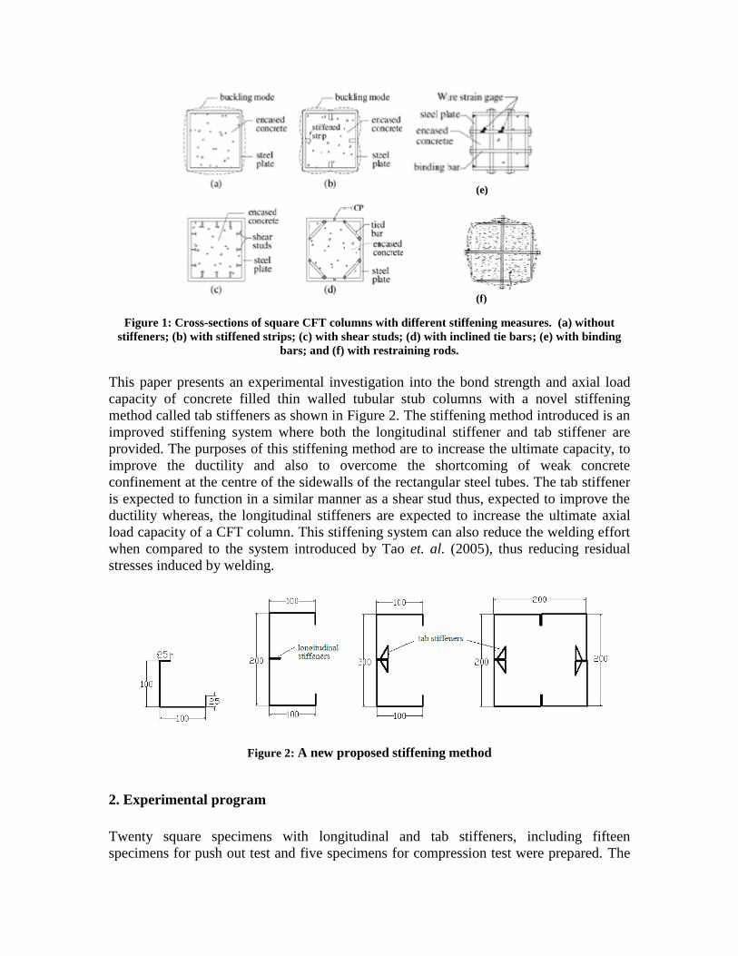
Figure 1: Cross-sections of square CFT columns with different stiffening measures. (a) without
stiffeners; (b) with stiffened strips; (c) with shear studs; (d) with inclined tie bars; (e) with binding
bars; and (f) with restraining rods.
This paper presents an experimental investigation into the bond strength and axial load
capacity of concrete filled thin walled tubular stub columns with a novel stiffening
method called tab stiffeners as shown in Figure 2. The stiffening method introduced is an
improved stiffening system where both the longitudinal stiffener and tab stiffener are
provided. The purposes of this stiffening method are to increase the ultimate capacity, to
improve the ductility and also to overcome the shortcoming of weak concrete
confinement at the centre of the sidewalls of the rectangular steel tubes. The tab stiffener
is expected to function in a similar manner as a shear stud thus, expected to improve the
ductility whereas, the longitudinal stiffeners are expected to increase the ultimate axial
load capacity of a CFT column. This stiffening system can also reduce the welding effort
when compared to the system introduced by Tao et. al. (2005), thus reducing residual
stresses induced by welding.
Figure 2: A new proposed stiffening method
2. Experimental program
Twenty square specimens with longitudinal and tab stiffeners, including fifteen
specimens for push out test and five specimens for compression test were prepared. The
(e)
(f)
push out test and compression test were conducted to determine the bond strength
between the steel and concrete interface and the axial load capacity. The primary
parameters studied were the tab stiffener spacing and the behaviour of different type of
stiffeners.
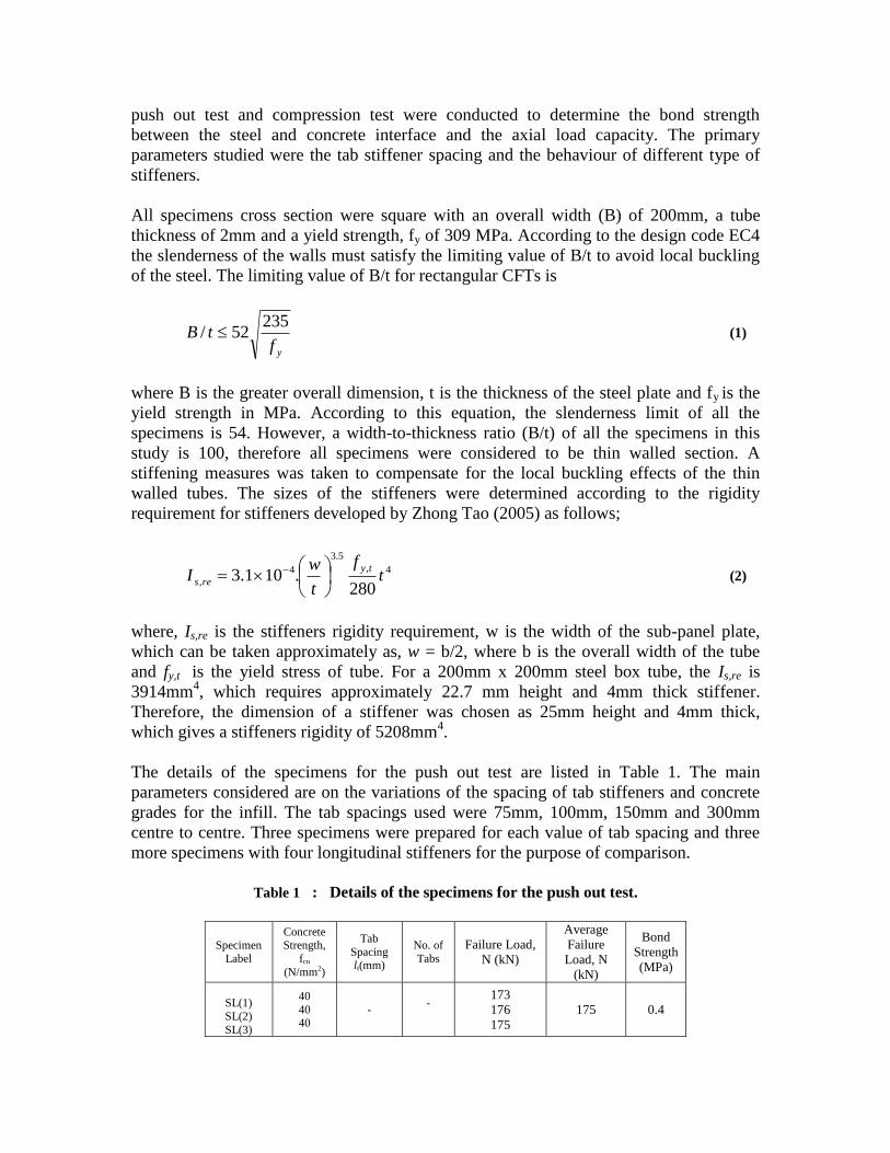
All specimens cross section were square with an overall width (B) of 200mm, a tube
thickness of 2mm and a yield strength, fy of 309 MPa. According to the design code EC4
the slenderness of the walls must satisfy the limiting value of B/t to avoid local buckling
of the steel. The limiting value of B/t for rectangular CFTs is
yftB
23552/ (1)
where B is the greater overall dimension, t is the thickness of the steel plate and fy is the
yield strength in MPa. According to this equation, the slenderness limit of all the
specimens is 54. However, a width-to-thickness ratio (B/t) of all the specimens in this
study is 100, therefore all specimens were considered to be thin walled section. A
stiffening measures was taken to compensate for the local buckling effects of the thin
walled tubes. The sizes of the stiffeners were determined according to the rigidity
requirement for stiffeners developed by Zhong Tao (2005) as follows;
4,
5.3
4
,280
.101.3 tf
t
wI
ty
res
(2)
where, Is,re is the stiffeners rigidity requirement, w is the width of the sub-panel plate,
which can be taken approximately as, w = b/2, where b is the overall width of the tube
and fy,t is the yield stress of tube. For a 200mm x 200mm steel box tube, the Is,re is
3914mm4, which requires approximately 22.7 mm height and 4mm thick stiffener.
Therefore, the dimension of a stiffener was chosen as 25mm height and 4mm thick,
which gives a stiffeners rigidity of 5208mm4.
The details of the specimens for the push out test are listed in Table 1. The main
parameters considered are on the variations of the spacing of tab stiffeners and concrete
grades for the infill. The tab spacings used were 75mm, 100mm, 150mm and 300mm
centre to centre. Three specimens were prepared for each value of tab spacing and three
more specimens with four longitudinal stiffeners for the purpose of comparison.
Table 1 : Details of the specimens for the push out test.
Specimen
Label
Concrete Strength,
fcu
(N/mm2)
Tab
Spacing lt(mm)
No. of
Tabs
Failure Load,
N (kN)
Average
Failure
Load, N
(kN)
Bond
Strength
(MPa)
SL(1)
SL(2)
SL(3)
40
40 40
- -
173
176
175
175 0.4
ST75(1) ST75(2)
ST75(3)
40 40
40
75 75
75
10
260
265
264
263 0.60
ST100(1)
ST100(2) ST100(3)
40
40 40
100
100 100
8
249
284
253
262 0.60
ST150(1)
ST150(2)
ST150(3)
40
40
40
150
150
150
6
220
192
268
227 0.52
ST300(1)
ST300(2)
ST300(3)
40
40
40
300
300
300
4
222
208
*
215 0.49
For the specimen designation, the letter S refer to the cross sectional shape and the
following letter L or T refer to longitudinal or tab stiffeners. The following number is the
tab spacing with the numeric character in bracket indicating the number of identical
specimens.
Table 2: Short column specimen details.
Table 2 presents the details of the specimens used for the compression test to preliminary
determine the ultimate axial load capacity of CFT column with tab stiffeners. The
specimens label starting with a L or T refer to longitudinal and tab stiffeners respectively.
The letter UC which follows, represent an empty steel column and CFT represent a
concrete filled column. The length of each specimen is chosen to be three times the
height of the square thin walled steel columns to avoid the effects of overall buckling and
end conditions.
2.1. Material Properties
All the specimens were fabricated from mild steel sheeting with a measured thickness of
2mm. The yield strength and the elastic modulus of the steel sheeting were 309 MPa and
200 GPa respectively, which had been determined from tensile test on three coupons.
Normal strength concrete of grade 30 with a water cement ratio of 0.5 was used for the
infill. The compressive strength of concrete was determined from three 150mm cubes
Specimens
label
lc
(mm c/c)
fcu
(N/mm2)
fy
(MPa)
Nue
(kN) DI
LUC1
TUC2
LCFT1
TCFT1
TCFT2
-
150
-
150
150
-
-
36
36
36
300
300
300
300
300
347
312
1280
1291
1301
2.67
1.71
2.85
2.11
2.63
taken from each batch of concrete. The average concrete cube strength (fcu) at 28 days
was 40MPa and 36 MPa for push out tests and compressive tests respectively.
2.2. Specimen Preparations
The steel tubes with longitudinal and tab stiffeners used for this study are
manufactured from mild steel sheeting with a measured thickness of 2 mm. The steel
sheeting was cut and pressed to form a lipped equal angle of 100mm x 100mm width x
600mm long and 25mm lip height. Two pieces of the lipped angles were welded
throughout its length to form a lipped channel with longitudinal stiffeners. The tab
stiffeners were then made by notching the lip in the middle slanting 50mm downward
with about 5mm tolerance at a required spacing and folding them horizontally in the right,
and left directions subsequently. Finally, a square tube with two longitudinal stiffeners
and two tab stiffeners was produced by seam welding together two pieces of lipped
channel with tab stiffeners. Steel tubes with four longitudinal stiffeners was also provided
by seam welding four pieces of lipped angle section as a comparison purpose. The
details of the specimens are shown in Figure 3(a) and (b).
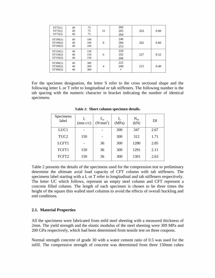
Figure 3: (a) the steel box column with two tab stiffeners and two longitudinal stiffeners and (b) the
steel box column with four longitudinal stiffeners as control specimen.
Fifteen square hollow steel section 200mm x 200mm wide and 2mm thick specimens
with stiffeners were prepared for the push out test. Each specimen is 600mm long, and
the length of the steel-concrete interface has been maintained at approximately 550mm.
Three specimens having four longitudinal stiffeners were prepared to act as control
specimens. Four different values of tab spacing i.e 75mm, 100mm, 150mm and 300mm
were considered. For each value of the tab spacing, three specimens were filled with
concrete. The bottom of the specimen was stiffened by welding four pieces of 200mm
width x 100mm height x 3mm thick plate to avoid any local buckling at the bottom part
of the steel box during testing. A tiny V notch of 7mm was provided at the bottom of the
tubes to release any trap air during testing.
During concrete casting, the specimens were placed in an upside down position and filled
with concrete to a length of 550mm leaving a 50mm gap at the top of the specimen. The
50mm air gap was provided to allow the concrete core to travel during testing.
Five specimens, including three specimens with tab stiffeners and two specimens with
longitudinal stiffeners were prepared for the compression test. A 2mm thick square flat
plate of 250mm width was welded to the base of the steel tubes in order to support the
wet concrete during casting.
The concrete was placed in layers for all specimens and was vibrated by a poker vibrator.
After the concrete had been cast into the steel hollow section, the specimens were left
with the top open to the air until testing. Prior to testing, the top and bottom surfaces of
the empty columns were cut and ground smooth to ensure that the load was applied
evenly across the cross section.
2.3. Test set-up and instrumentation
A 2000 kN capacity universal testing machine was used for both the push out and
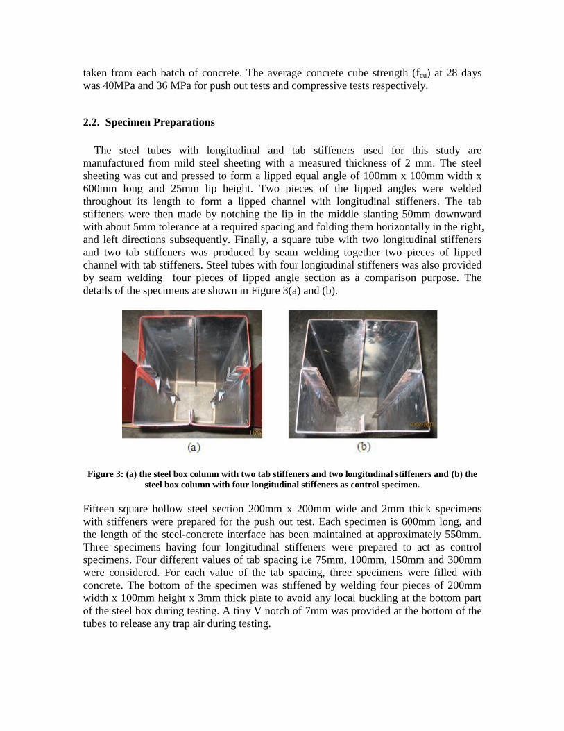
compressive tests. The test set-up for the push out test is shown in Figure 4. A 50mm
thick steel loading pad with sides about 10mm smaller than the internal dimension of the
specimens being tested was placed at the top end between the specimen and the loading
surface of the testing machine. The steel loading pad is provided with four grooves of
30mm x 8mm at its mid sidewall to accommodate the steel tube’s stiffeners. Four 50mm
travel electrical transducers were placed at the middle of each edge of the steel tube to
measure the movement of the concrete core with respect to the steel tube. The push out
test was performed at a displacement rate of 0.01mm per second. The movement of the
concrete core is taken to be the average of the four transducers readings. The load was
applied through the steel block to the concrete, which could then move vertically relative
to the steel section when the bond resistance of the concrete steel interface had exceeded.
Figure 4: Push Out Test set up and Instrumentation
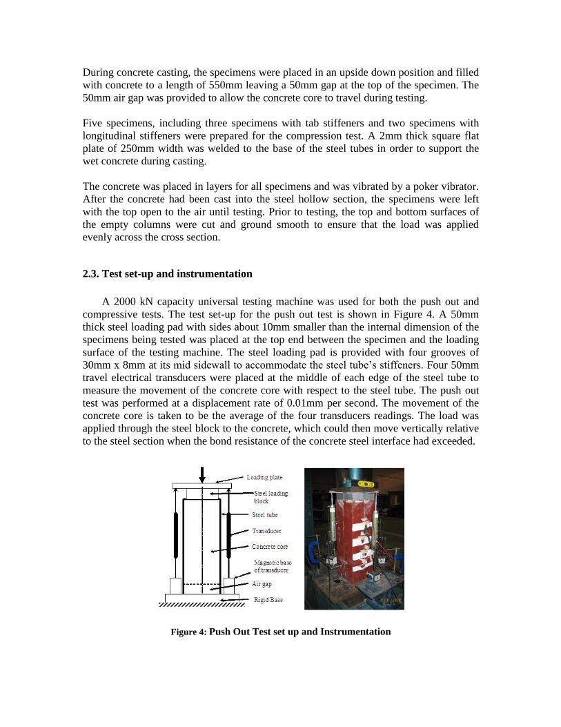
For the compression test, a 2000 kN capacity universal testing machine was used. A
computerized IMP data acquisition system was used for data logging. Four displacement
transducers were used to measure the axial shortening during the test. A load increment
of less than one tenth of the estimated load capacity was used. Each load increment was
maintained for about 2 minutes.
Figure 5: Compression test set up and instrumentations
3. Experimental results and discussion
3.1. Bond strength
The slip of the concrete core was recorded by the use of the displacement transducers.
A summary of the test results and bond strengths of the specimens were determined and
presented in Table 2. The load carrying capacity of the tab stiffener is determined by
subtracting the average failure load of the specimen from the control specimen. This
would give an average load carrying capacity of 88kN, 87kN, 52kN and 40kN for 10, 8, 6
and 4 numbers of tab stiffeners respectively. Therefore, each tab stiffener has a carrying
load capacity in average of about 10kN. If this value is compared to the carrying capacity
of the M12 bolt studied by Shakir-Khalil, (1991), the tab stiffener attained only about
13% of the carrying capacity of the M12 bolts. This indicates that tab stiffeners do
contribute to the enhancement of bond resistance at the steel concrete interface compared
to un-stiffened CFT [7, 8].
The bond strength at the interface between the steel and the concrete is calculated from
the equation:
Fb = N/A (3)
where, Fb is the bond strength at the steel concrete interface, N is the failure load applied
to the specimen and A is the contact area at the steel concrete interface.
The average bond strength of the control specimens give an average bond strength of
0.4MPa which is equivalent to the design shear strength value assumed in EC4 for
concrete filled rectangular hollow sections. The rest of the specimens show significant
improvement in the bond strength, which is as high as 50%.
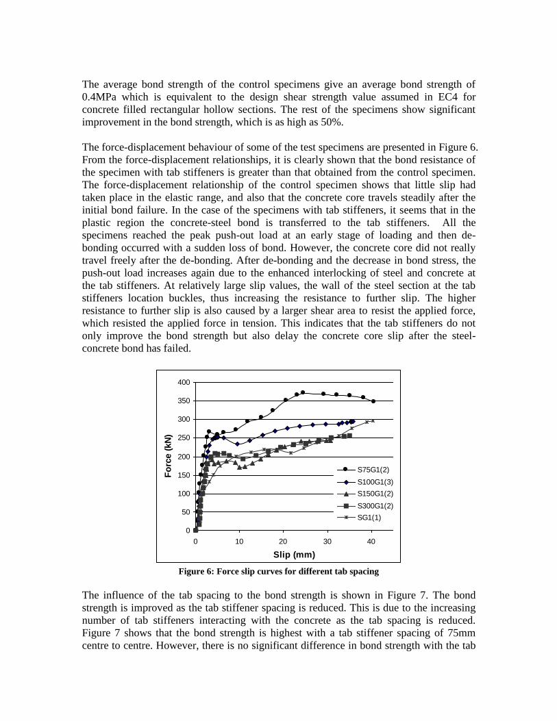
The force-displacement behaviour of some of the test specimens are presented in Figure 6.
From the force-displacement relationships, it is clearly shown that the bond resistance of
the specimen with tab stiffeners is greater than that obtained from the control specimen.
The force-displacement relationship of the control specimen shows that little slip had
taken place in the elastic range, and also that the concrete core travels steadily after the
initial bond failure. In the case of the specimens with tab stiffeners, it seems that in the
plastic region the concrete-steel bond is transferred to the tab stiffeners. All the
specimens reached the peak push-out load at an early stage of loading and then de-
bonding occurred with a sudden loss of bond. However, the concrete core did not really
travel freely after the de-bonding. After de-bonding and the decrease in bond stress, the
push-out load increases again due to the enhanced interlocking of steel and concrete at
the tab stiffeners. At relatively large slip values, the wall of the steel section at the tab
stiffeners location buckles, thus increasing the resistance to further slip. The higher
resistance to further slip is also caused by a larger shear area to resist the applied force,
which resisted the applied force in tension. This indicates that the tab stiffeners do not
only improve the bond strength but also delay the concrete core slip after the steel-
concrete bond has failed.
0
50
100
150
200
250
300
350
400
0 10 20 30 40
Slip (mm)
Fo
rce (
kN
)
S75G1(2)
S100G1(3)
S150G1(2)
S300G1(2)
SG1(1)
Figure 6: Force slip curves for different tab spacing
The influence of the tab spacing to the bond strength is shown in Figure 7. The bond
strength is improved as the tab stiffener spacing is reduced. This is due to the increasing
number of tab stiffeners interacting with the concrete as the tab spacing is reduced.
Figure 7 shows that the bond strength is highest with a tab stiffener spacing of 75mm
centre to centre. However, there is no significant difference in bond strength with the tab
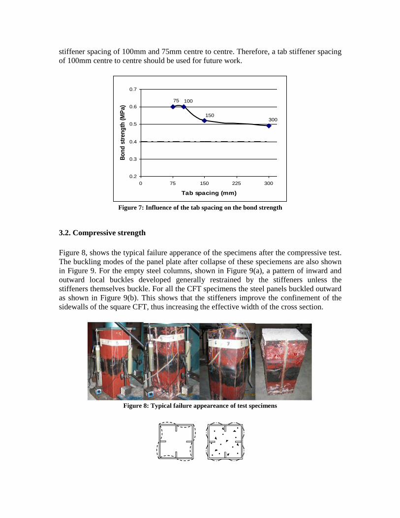
stiffener spacing of 100mm and 75mm centre to centre. Therefore, a tab stiffener spacing
of 100mm centre to centre should be used for future work.
300150
10075
0.2
0.3
0.4
0.5
0.6
0.7
0 75 150 225 300
Tab spacing (mm)
Bo
nd
str
en
gth
(M
Pa)
Figure 7: Influence of the tab spacing on the bond strength
3.2. Compressive strength
Figure 8, shows the typical failure apperance of the specimens after the compressive test.
The buckling modes of the panel plate after collapse of these speciemens are also shown
in Figure 9. For the empty steel columns, shown in Figure 9(a), a pattern of inward and
outward local buckles developed generally restrained by the stiffeners unless the
stiffeners themselves buckle. For all the CFT specimens the steel panels buckled outward
as shown in Figure 9(b). This shows that the stiffeners improve the confinement of the
sidewalls of the square CFT, thus increasing the effective width of the cross section.
Figure 8: Typical failure appeareance of test specimens
(a) (b)
Figure 9: Local buckling modes of test specimens: (a) stiffened steel column;
(b) stiffened CFT column.
Local buckling occured initially at the upper end of the specimen, then the steel panels
buckled at different locations, including the central part of the speciemens. It started with
the apperance of several fine lines at 45o to the principal axis of the tube at about 1000
kN, extending steadidly as the force was increased. Finally, buckling deformations
developed swiftly at one of these loactions, normally near the mid height of the column.
There is no significant differences in the buckling modes of all the steel panels at the tab
stiffeners and the longitudinal stiffeners faces.
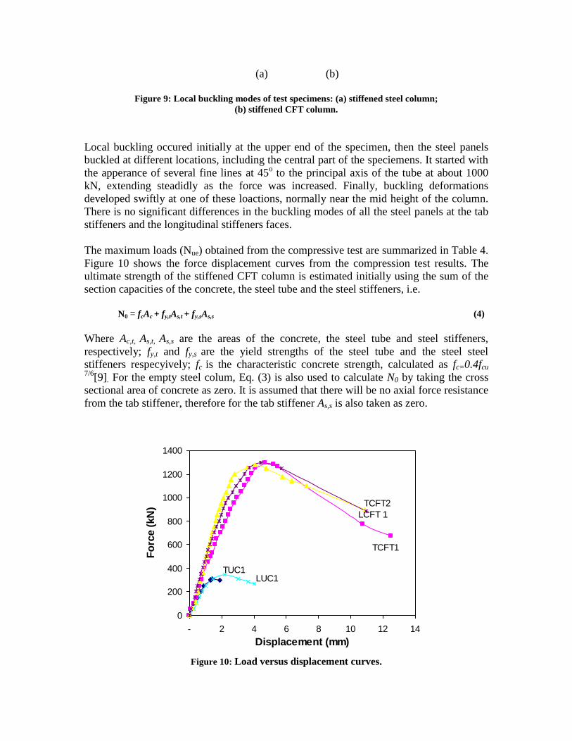
The maximum loads (Nue) obtained from the compressive test are summarized in Table 4.
Figure 10 shows the force displacement curves from the compression test results. The
ultimate strength of the stiffened CFT column is estimated initially using the sum of the
section capacities of the concrete, the steel tube and the steel stiffeners, i.e.
N0 = fcAc + fy,tAs,t + fy,sAs,s (4)
Where Ac,t, As,t, As,s are the areas of the concrete, the steel tube and steel stiffeners,
respectively; fy,t and fy,s are the yield strengths of the steel tube and the steel steel
stiffeners respecyively; fc is the characteristic concrete strength, calculated as fc=0.4fcu 7/6
[9]. For the empty steel colum, Eq. (3) is also used to calculate N0 by taking the cross
sectional area of concrete as zero. It is assumed that there will be no axial force resistance
from the tab stiffener, therefore for the tab stiffener As,s is also taken as zero.
0
200
400
600
800
1000
1200
1400
- 2 4 6 8 10 12 14
Displacement (mm)
Fo
rce (
kN
)
TUC1LUC1
TCFT1
LCFT 1
TCFT2
Figure 10: Load versus displacement curves.
The ultimate axial load capacity values obtained in the experimental investigation were
slightly higher than the predicted values for all the CFT specimens. However, the
ultimate axial load capacity of the empty tubes were overestimated by 44%. For the
empty steel tubes, the maximum load capacity of the empty steel tubes with longitudinal
stiffeners, LUC1 is higher than the empty steel tube with tab stiffeners, TUC1. This result
is expected because when the stiffeners has been cut and folded horizontally in the right
and left directions, the stiffener’s strength in the longitudinal direction decreases.
Therefore, the lip is no longer beneficial to the force resistance in the axial direction.
The ultimate strength of the stiffened CFT columns was greatly increased as a direct
result of the concrete infilling. It is noted that the compressive strength of the specimens
with tab stiffeners, TCFT1 and TCFT2 are slightly higher compared to the specimen with
longitudinal stiffeners, LCFT1. The result shows that the tab stiffener does contribute to
the improvement of the ultimate axial load capacity of CFT. This is due to the
improvement of the bond strength of the tab stiffeners that compensates the loss of its
axial stiffness.
3.2.1. Load carrying capacity prediction
The are several design codes used for predicting the capacity of CFTs, such as ACI,
BS5400 and EC4. In this paper the design equation recommended in the codes mentioned
above are applied to predict the sections axial load capacity of CFT with tab stiffeners.
These equations are used with some modifications to take into account the contribution of
the stiffeners. The predicted strength using ACI[9], BS5400 [10] and EC4 [11] compared
with the current experimental values of the test specimens with tab stiffeners are
presented in Table 3.
Table 3: Comparison between predicted ultimate strengths and test results
The nominal strength of CFT short columns according to ACI, BS5400 and EC4 is given
in Eq. (5), (6), and (7) as follows,
NACI = Asfy + 0.85Acf’c (5)
NBS5400 = Asfy + 0.675Acfcu (6)
Specimen
label
lc
(mm c/c)
Nue
(kN)
NACI
(kN) NACI/Nue
NBS5400
(kN) NBS5400/Nue
NEC4
(kN) NEC4/Nue
LUC1
TUC2
LCFT1
TCFT1
TCFT2
-
150
-
150
150
347
312
1280
1291
1301
590
530
1570
1510
1510
1.7
1.69
1.23
1.17
1.16
590
530
1523
1464
1464
1.7
1.69
1.19
1.13
1.13
590
530
1743
1682
1682
1.7
1.69
1.36
1.30
1.29
NEC4 = Asfy + Acf’c (7)
where As and Ac are the area of steel and concrete respectively; f’c and fcu are the
characteristic compressive cylinder and cube strength of the concrete respectively, while
fy is the yield strength of the steel tube. The area of steel As in this paper replaced by As,t
+ As,s to take the contribution of the stiffeners into consideration.
As can be seen in Table 3, Eq. (5), (6), and (7) overestimates the strength of the
specimens with longitudinal stiffeners by 23%, 19% and 36% respectively and about
16%, 13% and 29% for the specimens with tab stiffeners. The reason for all of the
specimens showing a lower strength could be explain by inadequate spacing of the tab
stiffeners. For the compression test, the spacing of the tab stiffeners is 150mm centre to
centre. A higher strength should be achieved if the spacing is decrease as the bond
strength between the steel concrete interface is increased with decreasing spacing of tab
stiffeners. Another reason could be due to residual stresses and the degradation of the
steel material as a result of excessive heat during the welding process. Because the tubes
are thin walled steel section, extra caution is needed during the fabrication process.
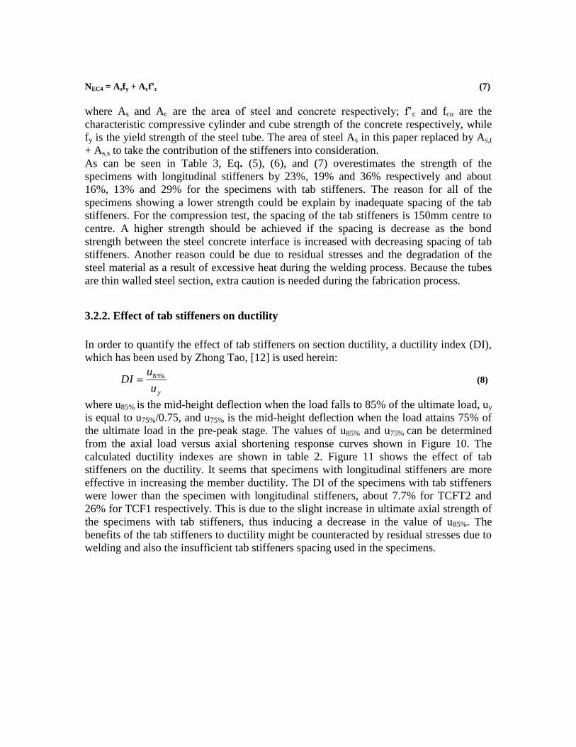
3.2.2. Effect of tab stiffeners on ductility
In order to quantify the effect of tab stiffeners on section ductility, a ductility index (DI),
which has been used by Zhong Tao, [12] is used herein:
yu
uDI %85 (8)
where u85% is the mid-height deflection when the load falls to 85% of the ultimate load, uy
is equal to u75%/0.75, and u75% is the mid-height deflection when the load attains 75% of
the ultimate load in the pre-peak stage. The values of u85% and u75% can be determined
from the axial load versus axial shortening response curves shown in Figure 10. The
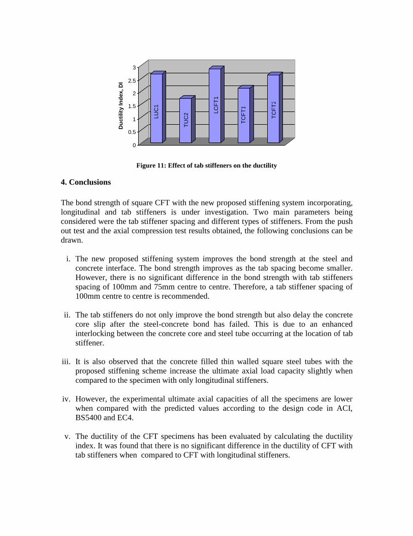
calculated ductility indexes are shown in table 2. Figure 11 shows the effect of tab
stiffeners on the ductility. It seems that specimens with longitudinal stiffeners are more
effective in increasing the member ductility. The DI of the specimens with tab stiffeners
were lower than the specimen with longitudinal stiffeners, about 7.7% for TCFT2 and
26% for TCF1 respectively. This is due to the slight increase in ultimate axial strength of
the specimens with tab stiffeners, thus inducing a decrease in the value of u85%. The
benefits of the tab stiffeners to ductility might be counteracted by residual stresses due to
welding and also the insufficient tab stiffeners spacing used in the specimens.
LU
C1
TU
C2 L
CF
T1
TC
FT
1
TC
FT
2
0
0.5
1
1.5
2
2.5
3
Du
cti
lity
In
dex, D
I
Figure 11: Effect of tab stiffeners on the ductility
4. Conclusions
The bond strength of square CFT with the new proposed stiffening system incorporating,
longitudinal and tab stiffeners is under investigation. Two main parameters being
considered were the tab stiffener spacing and different types of stiffeners. From the push
out test and the axial compression test results obtained, the following conclusions can be
drawn.
i. The new proposed stiffening system improves the bond strength at the steel and
concrete interface. The bond strength improves as the tab spacing become smaller.
However, there is no significant difference in the bond strength with tab stiffeners
spacing of 100mm and 75mm centre to centre. Therefore, a tab stiffener spacing of
100mm centre to centre is recommended.
ii. The tab stiffeners do not only improve the bond strength but also delay the concrete
core slip after the steel-concrete bond has failed. This is due to an enhanced
interlocking between the concrete core and steel tube occurring at the location of tab
stiffener.
iii. It is also observed that the concrete filled thin walled square steel tubes with the
proposed stiffening scheme increase the ultimate axial load capacity slightly when
compared to the specimen with only longitudinal stiffeners.
iv. However, the experimental ultimate axial capacities of all the specimens are lower
when compared with the predicted values according to the design code in ACI,
BS5400 and EC4.
v. The ductility of the CFT specimens has been evaluated by calculating the ductility
index. It was found that there is no significant difference in the ductility of CFT with
tab stiffeners when compared to CFT with longitudinal stiffeners.
Generally, the proposed stiffening method can improve the bond strength and the
ultimate strength capacity of concrete filled thin walled tubes provided the stiffeners are
adequately design. Since the proposed stiffening method for concrete filled thin walled
steel tubes shows encouraging behaviour in terms of improving the bonding strength,
ultimate axial capacity and ductility, more intensive research work will be conducted in
the future.
Acknowledgements
The authors would like to acknowledge the contribution of VPN Engineering Sdn Bhd in
fabricating and supplying the steel materials. Thanks to all the technicians at concrete and
heavy structures laboratories at UiTM for their dedication and cooperation while carrying
the experimental work.
References
1. Cai, J. and Z.-Q. He, Axial load behavior of square CFT stub column with binding
bars. Journal of Constructional Steel Research, 2006. 62(5): p. 472-483.
2. Hsu, H.L. and H.L. Yu, Seismic performance of concrete-filled tubes with
restrained plastic hinge zones. Journal of Constructional Steel Research, 2003.
59(5): p. 587-608.
3. Tao, Z., L.-H. Han, and Z.-B. Wang, Experimental behaviour of stiffened
concrete-filled thin-walled hollow steel structural (HSS) stub columns. Journal of
Constructional Steel Research, 2005. 61(7): p. 962-983.
4. Zhang, Y., C. Xu, and X. Lu, Experimental study of hysteretic behaviour for
concrete-filled square thin-walled steel tubular columns. Journal of
Constructional Steel Research, 2007. 63(3): p. 317-325.
5. J. Punchin, N. Krstulovic-Opara, and B. Brezac, High Strength Lightweight
Aggregate Fiber-Reinforced Concrete (HS-LWA FRC) Filled Steel Tube Columns
for Increased Seismic Resistance. American Concrete Institute, 2003: p. 33-48.
6. Shakir-Khalil, H. Bond strength in concrete-filled steel hollow sections. in
International Conference on Steel & Aluminium Structures 1991. Singapore:
Elsevier Applied Science.
7. Hunaiti, Y.M., Bond strength in battened composite columns. Journal of
Structural Engineering, 1991. 117: p. 699-714.

8. Huniati, Y.M., Composite action of foamed and lightweight aggregate concrete.
Journal of Materials in Civil Engineering, 1996. 8: p. 111-113.
9. ACI Committee 318, Building code requirements for reinforced concrete (ACI
318-99) and commentary (ACI 318R-99). 1999, American Concrete Institute:
Detroit.
10. BS5400, Steel, concrete and composite bridges. Part 5, Code of practice for the
design of composite bridges. 2005: London, UK.
11. Eurocode 4, ed. Design of composite steel and concrete structures - Part 1-1:
General rules and rules for buildings. ed. B. Standard. 2004, BSI.
12. Tao, Z., L.-H. Han, and D.-Y. Wang, Experimental behaviour of concrete-filled
stiffened thin-walled steel tubular columns. Thin-Walled Structures, 2007. 45(5):
p. 517-527.


![Inorganica Chimica Acta - University of Oxfordusers.ox.ac.uk/~dplb0149/publication/pub244.pdf · use steam-purified and shortened single-walled carbon nanotubes (SWCNTs) [36] filled](https://img.dokumen.tips/doc/110x75/5fa1ccc769d00633590d929d/inorganica-chimica-acta-university-of-dplb0149publicationpub244pdf-use-steam-purified.jpg)