Embed Size (px)
Citation preview

Experimental and Numerical Study on Vibration of Industry Driven Woven Fiber
Carbon/Epoxy Laminated Composite Plates
N. Nayak, S. Meher, and S. K. Sahu
Department Of Civil Engineering
National Institute of Technology, Rourkela
Email: [email protected]
ABSTRACT
The present research is an experimental and numerical investigation on parametric study of
vibration characteristics of industry driven woven fiber carbon composite panels. The effects of
different geometry, boundary conditions, lamination parameters and fibre on the frequencies of
vibration of carbon fiber reinforced polymer (CFRP) panels are studied in this investigation. The
vibration study is carried out using B &K FFT analyzer, accelerometer, impact hammer
excitation. The PULSE software is used to convert the responses from time domain to frequency
domain. The Frequency Response Function (FRF) spectrum are studied with the coherences to
obtain a clear understanding of the vibration characteristics of the CFRP plates. The
experimental results are compared with the numerical predictions using the FEM program as
well as software package ANSYS 13.0. A very good agreement was observed between the
results. Different mode shapes were plotted to interpret the different modes of vibration using
ANSYS. Benchmark results are presented showing the effects of different parameters on the
natural frequencies of CFRP plates.
KEYWORDS
Vibration, CFRP, modal testing, FRF spectrum, FFT, FEM
1. Introduction
Composite materials have extensive applications in various fields including fuselage panels of
aeroplane, turbine blades, automobile body panels, cryogenic fuel tanks etc. The recent Boeing
787 uses nearly 50% of composites of which the major components including fuselage and wings
consists of carbon composites. Thus, the vibration characteristics of the woven fibre laminated
composite panels are of tremendous practical importance in prediction of the dynamic behaviour
of carbon composite panels.
Most of the previous investigations were focused either on numerical analysis of unidirectional
composite plates. The related literature was critically reviewed so as to provide the background
information on the problems to be considered in the research work and to emphasize the
relevance of the present study. Most of the previous studies are limited to theoretical results by
adopting various methods including analytical and numerical approach like Ritz and finite
element method but with unidirectional fibres. The experimental results on vibration

measurement or modal analysis of composite plates are less in open literature. Cawley and
Adams [1] investigated the natural modes of square aluminium plates and square composite
plates with different ply orientations for free-free boundary conditions, both theoretically as well
as experimentally. Cawley and Adams [2] also used dynamic analysis to detect, locate and
roughly quantify damage to components fabricated from fibre reinforced plastic. Crawley [3]
experimentally determined the mode shapes and natural frequencies of composite plates,
cylindrical shell sections and Aluminium hybrid plates for various laminates and aspect ratio
using electro-magnetic shaker and compared the results to that obtained from finite element
analysis. The natural frequency and the specific damping capacity of CFRP and GFRP were
predicted by Lin et al. [4] using zoom-FFT based on transient testing technique and computer
based programme implementing finite element method. Chai [5] presented an approximate
method based on Rayleigh-Ritz approach to determine the free vibration frequencies of generally
laminated composites for different ply orientation and different boundary conditions. Maiti and
Sinha [6] used the first order shear deformation theory (FSDT) and higher order shear
deformation theories (HSDT) to develop FEM methods to study the bending, free vibration and
impact response of thick laminated composite plates. The effects of delamination on the free
vibration of composite plates were analysed by Ju et al. [7]. Chen and Chou [8] developed 1D
elasto-dynamic analysis method for vibration analysis orthogonal woven fabric composites. The
free vibration frequencies of cross ply laminated square plates for twelve different boundary
conditions were determined using Ritz method by Aydogdu and Timarci [9]. Ferreira et al. [10]
conducted analytical studies using FSDT in radial basis functions procedure for moderately thick
symmetrically laminated composite plates. Xiang et al. [11] carried out ttheoritical studies of
laminated composite plates using Guassian radial basis functions and first order shear
deformation theory. Xiang and Wang [12] studied the free vibration analysis of symmetric
laminated composite plates using trigonometric theory and inverse multiquadriatic radial basis
function. Maheri [13] used theoretical predictions of modal response of square layered FRP
panel to study the variation of modal damping under various boundary conditions.
Woven fabric composites are a class of composite materials with a fully integrated, continuous
spatial fibre network that provide excellent integrity and conformability for advanced structural
composite applications. These materials have gained tremendous popularity for possessing
excellent durability, corrosion resistance and high strength to weight ratio. Ease of installation,
versatility, anti-seismic behaviour, electromagnetic neutrality, excellent fatigue behaviour and
fire resistance make it a better alternative to steel and other alloys. The studies on woven fiber
composites are limited to static/ impact studies, damage initiation or failure mode of woven or
braided composite plates. The computation of natural frequencies is important to predict the
behaviour of structures under dynamic loads. The modal analysis can be used a non-destructive
technique of assessment of stiffness of structures. Measurement of changes in vibrational
characteristics can be used to detect, locate and roughly quantify damage in CRPF panels. This
study is also necessary in order to avoid resonance of large structures under dynamic loading.
However vibration of industry driven woven fiber composite plates are scarce in literature.
Linear analysis on CFRP faced sandwich plates with an orthotropic aluminium honeycomb core
has done using principle of minimum total potential and double Fourier series by Kanematsu et
al. [14]. Chai et al. [15] used TV holography technique to obtain the vibrational response of the
unidirectional laminated carbon fibre-epoxy plates and carried out finite element studies
simultaneously. Chakraborty et al. [16] determined the frequency response of GFRP plates
experimentally and validated the results using commercial finite element package (NISA). The
analytical values were compared with the experimental values obtained with fully clamped
boundary condition. Holographic technique was used to study the modes and deflection. Hwang
and Chang [17] used impulse technique for vibration testing of composite plates for
determination elastic constants of materials and modelled undamped free vibration using
ANSYS 5.3. Lei et al. [18] studied the effect of different woven structures of the glass fibre on
the dynamic properties of composite laminates.
The present study deals with modal testing of CRFP plates and compared with the numerical
modelling using finite element in MATLAB environment and also by ANSYS. Various mode
shapes are plotted using ANSYS and discussed. The effects of different geometry, boundary
conditions and lamination parameters on the frequencies of vibration of carbon fiber reinforced
polymer (CFRP) panels are studied in this investigation.
2. Mathematical formulation
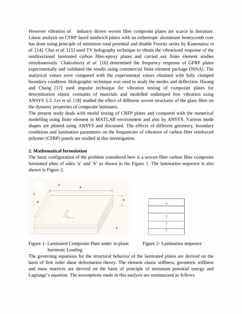
The basic configuration of the problem considered here is a woven fiber carbon fiber composite
laminated plate of sides ‘a’ and ‘b’ as shown in the Figure 1. The lamination sequence is also
shown in Figure 2.
Figure 1- Laminated Composite Plate under in-plane Figure 2- Lamination sequence
harmonic Loading
The governing equations for the structural behavior of the laminated plates are derived on the
basis of first order shear deformation theory. The element elastic stiffness, geometric stiffness
and mass matrices are derived on the basis of principle of minimum potential energy and
Lagrange’s equation. The assumptions made in this analysis are summarized as follows.

2.1. Governing Differential Equation
The equation of motion is obtained by taking a differential element of plate. The governing
differential equations for vibration of general laminated composite plates derived on the basis of
first order shear deformation theory (FSDT) are:
2
2
22
2
1t
Pt
uP
y
N
x
N xxyx
(1)
2
2
22
2
1t
Pt
vP
y
N
x
N yyxy
(2)
2
2
1t
wP
y
Q
x
Q yx
(3)
2
2
22
2
3t
uP
tPQ
y
M
x
M xx
xyx
(4)
2
2
22
2
3t
vP
tPQ
y
M
x
M y
y
yxy
(5)
Where Nx, Ny and Nxy are the in-plane stress resultants, Mx, My and Mxy are moment resultants
and Qx, Qy= transverse shear stress resultants.
dzzzPPPn
k
z
z
k
k
k
),,1()(),,( 2
1
321
1
(6)
Where n= number of layers of laminated composite plates, (ρ)k= mass density.
The equation of motion for vibration of a laminated composite panel, subjected to generalized in-
may be expressed in the matrix form as:
2[[K] [M]]{q} 0
(7)
2.2 Finite Element Formulation
For problems involving complex geometry, material and boundary conditions, analytical
methods are not easily adaptable and numerical methods like finite element methods (FEM) are
preferred. The finite element formulation is developed hereby for the structural analysis of

woven fiber composite plates based on first order shear deformation theory. An eight nodded
isoparametric element is employed in the present analysis with five degrees of freedom u, v, w,
θx and θy per node. A Composite plate of length ‘a’ and width ‘b’ consisting of ‘n’ number of thin
homogeneous arbitrarily oriented orthotropic layers having a total thickness ‘h’ is considered as
shown in figure 3. The x-y axes refer to the reference axes and the principal material axes are
indicated by the axes 1-2. The angle ‘θ’ measured in the anti-clockwise direction of x-axis
represents the fiber orientation. The displacement field assumes that mid-plane normal remains
straight before and after deformation, but not normal even after deformation so that:
0
xu(x, y,z) u (x, y) z (x, y)
0
yv(x, y,z) v (x, y) z (x, y) (8)
0w(x, y,z) w (x, y)
Where u, v, w are displacements in the x, y, z directions respectively for any point, u0,v
0, w
0 are
those at the middle plane of the plate. θx, θy are the rotations of the cross section normal to the y
and x axis respectively.
2.3 Strain Displacement Relations
The linear part of the strain is used to derive the elastic stiffness matrix. The linear generalized
shear deformable strain displacement relations are [6]
xl x
uzk
x
yl y
vzk
y
xyl xy
u vzk
y x
(9)
xzl x
w
x
yzl y
w
y
The bending strains kj are expressed as,
yxk
yxx
yk ,
yxxyk
y x
(10)

The linear strain can be expressed in terms of displacement as:
eB
(11)
Where ,,,,,..........,,,, 888881111
T
yxyxe wvuwvu (12)
And [B] = [[B1], [B2]………………………………. [B8]] (13)
(14)
[B] is called the strain displacement matrix
2.4 Constitutive Relations
The elastic behavior of each lamina is essentially two dimensional and orthotropic in nature. The
elastic constants for the composite lamina are given as [6 ].
The stress strain relation for the kth lamina is,
x x11 12
y y12 22
xy 66 xy
44xz xz
55yz yz
Q Q 0 0 0
Q Q 0 0 0
0 0 Q 0 0
0 0 0 Q 0
0 0 0 0 Q
(15)
Where
11 11 21 22 12 2211 12 21 22
12 21 12 21 12 21 12 21
66 12
44 13
55 23
E E E EQ ,Q ,Q ,Q
(1 ) (1 ) (1 ) (1 )
Q G
Q kG
Q kG
(16)
Where
8
1
,
,
,,
,
,
,,
,
,
000
000
000
0000
0000
000
0000
0000
i
iyi
ixi
yixi
yi
xi
xiyi
yi
xi
NN
NN
NN
N
N
NN
N
N
B

E11 = Modulus of Elasticity of Lamina along 1-direction
E22 = Modulus of Elasticity of Lamina along 2-direction
G12 = Shear Modulus
ν12= Major Poisson’s ratio
ν21 = Minor Poisson’s ratio
The on-axis elastic constant matrix [Qij]k for the material axes 1-2 for kth layer is given by
66
2212
1211
00
0
0
Q
Qkij For ji, = 1, 2, 6
(17)
55
44
0
0
Q
kij For ji, = 4, 5
For obtaining the off-axis elastic constant matrix, [Qij]k corresponding to any arbitrarily oriented
reference x-y axes for the kth
layer ,appropriate transformation is required. Hence the off-axis
elastic constant matrix is obtained from the on axis elastic constant matrix by the relation:
662616
262212
161211
kij
QQQ
QQQ
QQQ
Q for i ,j =1,2,6
(18)
[ Qij ]k = [
]
for i ,j =4,5
1
ij ijk k [Q ] T Q T
(19)
Where [T] = Transformation matrix =
k
22
22
22
nmmnmn-
2mn-mn
2mnnm

The off-axis stiffness values are:
)()22(
)2()2(
)2()2(
)2(2
)()4(
)2(2
44
66
22
6612221166
3
662212
3
66121126
3
662212
3
66121116
4
22
22
6612
4
1122
44
12
22
66221112
4
22
22
6612
4
1111
nmQnmQQQQQ
nmQQQmnQQQQ
mnQQQnmQQQQ
mQnmQQnQQ
nmQnmQQQQ
nQnmQQmQQ
(20)
The stiffness corresponding to transverse deformations are:
(21)
Where m=cosθ and n=sinθ; and θ=angle between the arbitrary principal axis with the material
axis in a layer.
The force and moment resultants are obtained by integrating the stresses and their moments
through the laminate thickness as given by
(22)
x x
y y
xy xy
h/2x x
y yh/2
xy xy
x xz
y yz
N
N
N
M zdz
M z
M z
Q
Q
2
23
2
1355
231345
2
23
2
1344
)(
mGnGQ
mnGGQ
nGmGQ

x11 12 16 11 12 16
y12 22 26 12 22 26
xy 16 26 66 16 26 66
x 11 12 16 11 12 16
y 12 22 26 12 22 26
16 26 66 16 26 66xy
44 45x
45 55y
N A A A B B B 0 0N A A A B B B 0 0
N A A A B B B 0 0
M B B B D D D 0 0
M B B B D D D 0 0
B B B D D D 0 0M
0 0 0 0 0 0 S SQ
0 0 0 0 0 0 S SQ
x
y
xy
x
y
xy
xz
yz
k
k
k
(23)
This can also be stated as
ji ij ij
i ij ij j
iji m
N A B 0
M B D 0 k
0 0 SQ
(24)
Or
F D (25)
Where Aij, Bij andSi j are the extensional, bending- stretching coupling, bending and transverse
shear stiffnesses. They may be defined as
1
1
kk
n
kkijij zzQA (26)
n
2 2
ij ij k k-1kk=1
1B = Q z -z
2 (27)
3
1
3
13
1
kk
k
n
k
ijij zzQD For ji, = 1, 2, 6 (28)
(23)
n
ij ij k k 1kk 1
S Q z z
For ji, = 4, 5 (29)
κ = shear correction factor =5/6 in-line with previous studies [Whitney and Pagano [1970] and
Reddy [1979]]
zk, zk-1= top and bottom distance of lamina from mid-plane.
2.5 Elastic stiffness matrix
The element matrices in natural coordinate system are derived as

T1 1
e 1 1K B D B J d d
(30)
Where [B] is called the strain displacement matrix
2.6 Element mass matrix
T1 1
e 1 1M N P N J d d
(31)
Where the shape function matrix
(32)
I
I
P
P
P
P
0000
0000
0000
0000
0000
1
1
1
1 (33)
In which,
n
k
ek
ek
dzP1 1
1 And dzzIn
K
ek
ek
1 1
2 (34)
The element load vector due to external transverse static load ‘p’ per unit area is given by
1 1
ie 1 1
p
P N 0 J d d
0
. (25)
8
1
0000
0000
0000
0000
0000
i
i
i
i
i
i
N
N
N
N
N
N

2.7. Computer Program
A computer program is developed by using MATLAB environment to perform all the necessary
computations. The element stiffness and mass matrices are derived using the formulation.
Numerical integration technique by Gaussian quadrature is adopted for the element matrices. The
overall matrices [K] and [M] are obtained by assembling the corresponding element matrices.
The boundary conditions are imposed restraining the generalized displacements in different
nodes of the discretized structure.
2.8 Modeling using ANSYS 13.0
The CFRP plate was modeled using a commercially available finite element package, ANSYS
13.0. [20] The natural frequencies and mode shapes are obtained by modal analysis. The element
type used is SHELL281 which is an 8 noded structural shell, suitable for analyzing thin to
moderately thick shell structures. The element has 8 nodes with 6 degrees of freedom at each
node. The accuracy in modeling composite shells is governed by the first order shear
deformation theory. The whole domain is divided into 8 x 8 mesh for all the cases. The boundary
conditions of CCCC, CSCS, SSSS and CFFF were introduced by limiting the degrees of freedom
at each node. FFFF condition was simulated by limiting displacement of the plate in vertical
direction along the plane of plate. This condition closely resembled the experimental used in
which the plate was hung vertically using strings of negligible stiffness.
3. Experimental Programme
The experimental investigation describes in detail of the materials and its fundamental
constituents, the fabrication of composite plates, and the test methods according to standards.
3.1 Fabrication Method
Specimens were cast using hand layup technique as shown in Figure 3. In hand lay-up method,
The percentage of fiber and matrix was taken as 50:50 by weight for fabrication of the plates.
Lamination started with the application of a gel coat (epoxy and hardener) deposited on the
mould by brush. Layers of reinforcement were placed on the mould at top of the gel coat and gel
coat was applied again by brush. Any air which may be entrapped was removed using steel
rollers. After completion of all layers, again a plastic sheet was covered the top of last ply by
applying polyvinyl alcohol inside the sheet as releasing agent. Again one flat ply board and a
heavy flat metal rigid platform were kept top of the plate for compressing purpose. The plates
were left for a minimum of 48 hours in room temperature before being transported and cut to
exact shape for testing.

Figure 3 - Hand Lay Up method used for fabrication
3.2 Determination of Physical Properties
The physical properties of fabricated composite plates such as density and thickness, represented
in Table 1, were measured up to the required degree of accuracy. The thickness was measured
using vernier caliper with a least count of 0.1 mm. The weight of the specimen was measured
using digital weighing balance with an accuracy of 0.1 grams.
Table 1- Physical properties of the casted specimens
Sl. No. No of
layers
Length in
m
Width in m Thickness
in m
Mass in g Density in
kg/m3
1 4 0.24 0.24 0.0021 174 1438.49
2 8 0.24 0.24 0.0042 345 1426.09
3 12 0.24 0.24 0.0065 519 1386.22
3.3 Tensile tests on CFRP plates
The Young’s modulus was obtained experimentally by performing unidirectional tensile tests on
specimens cut in longitudinal and transverse directions as described in ASTM Standard [19] for
the FRP plates fabricated earlier. Strips of specimens having a constant rectangular cross-section,
say 250 mm long × 25mm width are prepared from the plates. Three or more sample specimens
were prepared from each plate of CFRP in this experiment. The specimen is gradually loaded up
to failure, which was abrupt and sudden as the FRP material was brittle in nature. The INSTRON
1195 machine as shown in figure 4 directly indicated the Young’s Modulus, ultimate strength.

Figure 4: Tensile testing of CFRP plates using INSTRON 1195
3.4 Setup and Test Procedure for Free Vibration Test:
The connections of FFT analyzer, laptop, transducers, modal hammer, and cables to the system
were done as per the guidance manual. The pulse lab shop software key was inserted to the port
of laptop. The plate was excited in a selected point by means of Impact hammer (Model 2302-5).
The resulting vibrations of the specimens on the selected point were measured by an
accelerometer (B&K, Type 4507) mounted on the specimen by means of bees wax. The plates
were placed as per the required boundary conditions of free-free (FFFF), fully clamped (CCCC),
simply supported (SSSS), cantilevered (CFFF) and CSCS conditions. Fully clamped and free
free conditions were simulated as shown in figure 5(a) and 5(b).
(a) (b)
Figure 5: Carbon fibre composite plate during testing for different boundary conditions. (a) Fully
Clamped condition. (b) Free free condition for aspect ratio 4.

4. Results and Discussion
The predictions of natural frequency of vibration using finite element analysis and experimental
results are presented. Comparison with existing literature is done for the validation of the results
obtained from finite element analysis. The above results are compared with that of finite element
package, ANSYS. The experiments were conducted to study the modal frequencies of industry
driven woven carbon fibre composite plates. The variation of the fundamental frequencies with
boundary conditions, number of layers, aspect ratio and type of fibre were studied.
4.1 Material properties
The material properties of the carbon/epoxy composite are presented in Table 2.
Table 2 – Material properties of epoxy/carbon composite
E1 (GPa) 40.32 GPa
E2 (GPa) 40.32 GPa
G12 (GPa) 3.78 GPa
G13 (GPa) 3.5 GPa
ν12 0.3
ρ(kg/m3)
1426
4.2 Validation of results
The present formulation is validated for vibration analysis of composites panels in free-free
boundary conditions as shown in Table 3. The four lowest non dimensional frequencies obtained
by the present finite element are compared with numerical solution published by Ju et al. [7].The
experimental results were compared with analytical results as well as results from ANSYS, finite
element package. The comparison has been presented in the subsequent sections. A good
agreement was observed between the results with a maximum deviation of 20 % between
experimental and FEM program results and 7 % between FEM program ANSYS.
Table 3 - Comparison of natural frequencies (Hz) from FEM with the frequencies for 8 layers for
fully free boundary condition
Studies Mode 1 Mode 2 Mode 3 Mode 4
Ju et al. [7] 73.309 202.59 243.37 264.90
Present FEM 72.71 202.06 244.22 264.14
4.3 Modal Testing of Composite plates for different boundary conditions
Natural frequencies of the first four modes obtained experimentally and using FEM analysis for
various boundary conditions are represented in figures 6(a)-(e). The experimental values are in
good agreement with the predicted values with a maximum deviation 18.03%. There is a marked
increase in the modal frequencies with the increase in the number of layers of carbon fibre used
for a particular boundary condition. This can be accounted for due to bending, stretching and

coupling. It is also observed that the effect of plate thickness is most evident in case of FFFF
boundary condition.
(a) (b)
(c) (d)
(e)
Figure 6 – Variation of natural frequency with number of layers for (a) free-free (b) fully
clamped (c) cantilever (d) simply supported (e) CSCS boundary conditions.

The first four mode shapes for 8 layered plates were obtained from ANSYS 13.0 and are
illustrated in figures 7(a)-(e). It is observed that the frequencies for second and third modes are
quite close for FFFF, CCCC, SSSS, and CSCS boundary conditions since they represent
conjugate modes as evident from the mode shapes. A deviation from such behavior is noted in
case of CFFF boundary condition which can be attributed to asymmetry in boundary condition.
(a)
(b)
(c)
(d)

(e)
Figure 7 – Mode shapes for first four modes for 8 layered CFRP plate in (a) FFFF (b) CCCC (c)
CFFF (d) SSSS (e) CSCS boundary conditions.
The comparison of the natural frequencies of 8 layered CFRP plates for different boundary
conditions is shown in figure 8. The natural frequencies of vibration for CCCC condition are
observed to be higher than that of other boundary conditions. This is followed by CSCS, SSSS,
FFFF and CFFF in descending order. The greatest frequency in fully clamped condition can be
attributed to greater stiffness of supports. With decrease in restraints the modal frequencies
decrease.
Figure 8 – Comparison of natural frequency of 8- layer CFRP plates for different boundary
condition
The natural frequencies of vibration in FFFF boundary condition for aspect ratio 1, 2 and 4 are
presented in figure 9. Figure 10(a)-(b) shows the mode shapes for the first four modes for
different aspect ratios. It is observed that the modal frequencies increase with the increase in
aspect ratio. The frequencies are increased by nearly 47% as the aspect ratio is increased and an
almost linear variation was observed.

Figure 9 - Variation of natural frequency with aspect ratio
(a)
(b)
Figure 10 - Mode shapes for first four modes for 8 layered CFRP plate in FFFF boundary
condition with (a) a/b = 2 (b) a/b = 4.
The variation of natural frequency with type of fibre is shown in figure 11. The present values
obtained for CFRP plates have been compared with GFRP plates of equal dimension, reinforced
with E Glass Fibre having E= 7.8GPa, υ=0.33 and σ= 2160 kg/m2 obtained from Basa and
Dwibedi [21]. The natural frequencies obtained for CFRP plates are significantly greater than
those obtained for GFRP plates showing higher specific stiffness.The increase in frequencies is
more pronounced at higher modes.

Figure 11 Variation of natural frequency with type of fibre
5. Conclusion
Based on the discussions of results, the conclusions are:
Benchmark solutions on the natural frequencies of the first four modes are reported for
simply supported, fully clamped, cantilever, free-free and CSCS boundary conditions.
The mode shapes are plotted for CFRP plates supported on different boundaries.
The frequencies of woven fiber CFRP plates increase with increase of aspect ratio.
From the experiments conducted it was observed that the frequency of vibration of
composite plates increase with increase in the number of layers of fiber for all the support
conditions due to bending stretching coupling..
The frequency of vibration was noted to be highest for fully clamped condition due to the
increased stiffness.
When compared with the results reported for GFRP, it was observed that the modal
frequencies for CFRP were considerably higher than that of GFRP accounting for its
better performance.
From the present studies, it is concluded that the vibration behavior of woven fiber laminated
composite plates and shells is greatly influenced by the geometry and lamination parameter.
The figures dealing with variation of the frequencies are recommended as design aids for flat
panels. The above recommendations for design of composite plates are valid within the range
of geometry and material considered in this study. So the designer has to be cautious while
dealing with woven fiber composite plates. This can be utilized to the advantage of tailoring
during design of laminated composite structures. The vibration studies can also be used a non
destructive tool for damage detection and structural health monitoring of structures.

6. References
[1] Cawley, P. and Adams, R. D. The predicted and experimental natural modes of free-free
CFRP plates, Journal of Composite Materials, 12, 336-347, 1978.
[2] Cawley, P. and Adams, R. D., A Vibration Technique for Non-Destructive Testing of Fibre
Composite Structures. Journal of Composite Materials, 13, 161-175, 1979
[3] Crawley, E. F. The Natural Modes of Graphite/Epoxy Cantilever Plates and Shells.Journal of
Composite Materials, 13, 195-205, 1979.
[4] Lin, D.X., Ni R.G. and Adams R.D., Prediction and Measurement of vibrational damping
parameters of Carbon and Glass Fibre-Reinforced Plastic Plates. Journal of Composite
Materials, 18, 132, 1984.
[5] Chai, G. B., Free vibration of generally laminated composite plates with various edge support
conditions. Composite Structures, 29, 249-258, 1994.
[6] Maiti, D. K. and Sinha, P. K., Bending, free vibration and impact response of thick laminated
composite plates. Journal of Computers and Structures, 59, 115-129, 1996.
[7] Ju, F., Lee H.P., and LeeK.H.. Finite Element Analysis of Free Vibration of delaminated
Composite plates. Composite Engineering, 5, 195-205, 1995.
[8] Chen, B. and Chou, Tsu-Wei, Free vibration analysis of orthogonal-woven fabric composites.
Journal of Composites: Part A, 30, 285-297.
[9] Aydogdu, N and Timarci, T, Vibration analysis of cross ply laminated square plate with
general boundary conditions. Composite Science and Technology, 63, 1061-1070, 2003
[10] Ferreira, A. J. M., Roque, C. N. C. and Jorge, R. M. N., Free vibration analysis of
symmetric laminated composite plates by FSDT and radial basis function. Computer Methods in
Applied Mechanics and Engineering, 194, 4265-4278, 2005.
[11] Xiang, Song, Wang, Ke-ming., Ai, Yan-ting, Sha, Yun-dong and Shi, Hong. Natural
frequencies of generally laminated composite plates using the Gaussian radial basis function and
first-order shear deformation theory. Thin-Walled Structures, 47, 1265-1271, 2009.
[12] Xiang, Song and Wang, Ke-ming. Free vibration analysis of symmetric laminated
composite plates by trigonometric shear deformation theory and inverse multiquadric RBF. Thin-
Walled Structures, 47, 304-310, 2009.

[13] Maheri, M. R. The effect of layup and boundary conditions on the modal damping of FRP
composite panels. Journal of Composite Materials, 45(13) 1411-1422, 2010.
[14] Kanematsu, H. H., Hirano, Y. and Hisashi, I. Bending and Vibration of CFRP-Faced
Rectangular Sandwich Plates. Composite Structures, 10, 145-163, 1988.
[15] Chai, G.B., Chin, S. S., Lim, T. M. and Hoon, K. H. Vibration analysis of laminated
composite plates: TV-holography and finite element method. Composite Structures, 23, 273-283,
1993.
[16] Chakraborty, S., Mukhopadhyay, M. and Mohanty. A.R. Free vibrational responses of FRP
composite plates: experimental and numerical studies. Journal of Reinforced Plastics and
Composite, 19, 535-551, 2000.
[17] Hwang, Shun-Fa and Chang, Chao-Shui, Determination of elastic constants of materials by
vibration testing. Composite Structures, 49, 183-190, 2000.
[18] Lei X., Shujie W. R. Z. and Yong L., Vibration characteristics of glass fibre- epoxy
composites with different woven structure, Journal of Composite Materials, 2010.
[19] ASTM D 3039/D 3039 N, Standard test method for tensile properties of polymer matrix
composite materials.
[20] ANSYS user’s manual. Sawnson Analysis Systems Inc., 2010.
[21] Basa, D. and Dwibedi, S. Project thesis on Effects of cut-out on natural frequency of glass
fibre-epoxy composite plates. Department of Civil Engineering.National Institute of Technology,
Rourkela, 2012.