Embed Size (px)
Citation preview
Experiment – 8 Free And Forced Convection From Flat, Finned And Pinned Plates
Experiment
Aim of this Experiment
Free and Forced convection from Flat Finned and Pinned Plates experiments enables students
to investigateheat transfer from various surfaces in free and forced convection.
Experimental Set – up
The H112P Free and Forced convection from Flat Finned and Pinned Plates enables students to
investigateheat transfer from various surfaces in free and forced convection. The range of
heated plates demonstratesthe effect of extended surfaces (fins and pins) on the rate of heat
transfer. The H112P is designed to beused with, and to be installed alongside, the Heat Transfer
Service Unit H112.
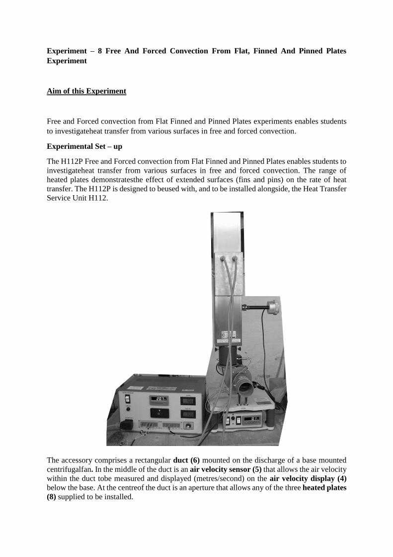
The accessory comprises a rectangular duct (6) mounted on the discharge of a base mounted
centrifugalfan. In the middle of the duct is an air velocity sensor (5) that allows the air velocity
within the duct tobe measured and displayed (metres/second) on the air velocity display (4)
below the base. At the centreof the duct is an aperture that allows any of the three heated plates
(8) supplied to be installed.

A flat plate, pinned plate, or finned plate heat exchanger may be installed in the duct and secured
by twotoggle clamps. Each exchanger incorporates an electric heater mat rated at 100W at
240V. Each of the heated plates incorporates thermostatic protection against overheating.
The heater surface temperature (T1) is continuously monitored and displayed by the
temperature indicatorwhen plugged in to the console.
The Pinned plate is fitted with three extra thermocouples (T2, 3 and 4) to measure the
temperature ofextended surfaces. T5 is furthest from the heater.
The Finned plate is fitted with three extra thermocouples (T2, 3 and 4) to measure the
temperature ofextended surfaces. T8 is furthest from the heater.
Note that the T4 distance is 50mm from the heater on the Pinned Plate and 46mm from the
heater onthe Finned Plate.

The T5 air temperature (7) sensor is located at the base of the duct and records the temperature
of the airflowing over the heated plate.
Thermocouple attachment points on the heat exchangers are protected by a covering of
adhesive.
The air velocity passing the heated plates can be varied from zero to more than 8m/s depending
upon thelocal mains voltage and supply frequency. The air velocity sensor(5) is permanently
mounted in theduct and connects to the console below using a line plug and socket.
The air velocity is controlled by the use of an intake air throttle (9). For natural convection
experiments,the fan may be switched off using the fan switch (3) on the H112P console.
All thermocouples terminated with a miniature plug (identifiedT1, and T2 to T4) for insertion
into thecontrol console sockets.
Schematic Representation of Linear Conduction Experiment Unit

Capabilities Of The Free and Forced Convection Unit
1. To Demonstrate the Relationship Between Power Input and Surface Temperature in Free
Convection
2. To Demonstrate the Relationship Between Power Input and Surface Temperature in
ForcedConvection.
3. To Demonstrate the use of Extended Surfaces to Improve Heat Transfer From the Surface.
4. To Determine the Temperature Distribution Along an Extended Surface.

Operating Procedure Of Free and Forced Convetion Unit
Note that the H112P may be operated with the HC112A Data Acquisition Upgrade. With the
addition ofthis option all data relating to the following experimental procedures may be
recorded automatically andtransferred to spreadsheet format for subsequent detailed analysis
and calculation.
The operation of the data acquisition upgrade is detailed in a separate manual but experimental
proceduresare identical to those described in the following text.
CAUTIONS
Active Element High Temperature Protection
Each of the heated plates (Flat, Finned and Pinned) incorporate a thermal protection thermostat.
This isdesigned to turn off the power to the heater if the element temperature exceeds
approximately 90-100°C.
This will show on the H112 console as a ZERO current demand. The mains voltage display
may not show zero as the voltage is measured at the console and the thermal switch is in the
heater box.
If the thermal cut out operates allow the element to cool and the thermostat will reset
automatically.
Hot Surfaces
Even with the high temperature protection the heated plates can reach 100°C and this is
sufficient to causeburns. NEVER touch the metal surface of the plates with bare hands when
the element is plugged into thecontrol console. Handle the plates using the plastic backing plate
only. Do not place the plates on anysurface that can be damaged by heat.
General Notes
Applicable to all experimental work.
Before using the Cross Flow Heat Exchanger the user should:
(i) Study the unit and schematic diagram to identify all switches and controls relating to both
theH112 Heat Transfer Service Unit H112 and the Free and Forced Convection from Flat,
Finnedand Pinned Plates H112P Accessory.
(ii) Understand the action of the various controls. Refer to the main H112 Heat Transfer
ServiceUnit manual.
(iii) Be aware of the Cautions regarding handling of hot surfaces.
(iv) Be aware of how to obtain stable running conditions..

Experiment -8.1
To Demonstrate the Relationship Between Power Input and SurfaceTemperature in Free
Convection
Aim of This Experiment
This experiment aim to establis relations between power input and surface temparature changes
during free convection.
Procedure
Optionals Method
As the rate of heat transfer in natural convection is typically very small, the time taken to reach
stability canbe very long and may exceed a laboratory period. For this reason two methods of
demonstrating naturalconvection using the three plates are described below.
a) Steady State Method
If time permits, or for a student project the steady state experimental procedure may be adopted.
Thisallows the heat transfer rate from the three heat exchangers to be compared at similar hot
platetemperatures. Due to the requirement for small adjustments and the time taken to assess
stability theexperimental period can be long.
b) Transient Method
However for a rapid demonstration the transient method may be adopted where a fixed heat
input is appliedin turn to each of the three heat exchangers and the temperature rise plotted
against time until the 100°C cutout point is reached.
With this method the slope of the temperature rise is an indication of the rate of heat transfer
from the plate.
a) Steady State Method
The same procedure is utilised for the three types of plate, Flat, Pinned and Finned.
(i) Ensure the instrument console main switch is sin the off position. Ensure the fan is switched
off.For the natural convection experiments the fan will not be used.
(ii) If the flat (pinned or finned) plate is not in position, open the toggle clamps. Replace with
theflat(pinned or finned) plate and close the toggle clamps. Note that with the plate heat
exchangersthe power leads exit from the top of the plates. Refer to the diagram on page 1
(iii) No air velocity will be measurable under natural convection conditions unless specialised
instrumentation is available.
(iv) Switch on the main switch and set the heater voltage to minimum.
The objective with the steady state method is to obtain the same T1 surface temperature on
eachof the heat exchangers and determine the steady state power input required to achieve this.
Fromfactory tests under “typical” conditions the following heat inputs were required to
maintain T1(approximately) 100°C

Where R is the electrical resistance (Ohms)of the heater element . The nominal resistance of
thestandard heater is 529 Ohms. The actual figure can be checked by calculating the
resultingmeasured V (volts) and I (current) to the heater and calculating
The best technique is to set the voltage input to maximum and monitor T1 on the
digitaltemperature indicator. When T1 approaches 100°C, reduce the voltage to the appropriate
level forthe plate heat exchanger in use.
(v) When the temperature T1 has stabilised(this may take 10’s of minutes) record the
actualtemperature T1, the actual voltage V and the ambient air temperature T9. If either the
Finned orPinned plates are in position the pin temperatures (T2,T3,T4) or fin temperatures (T2,
T3, T4)may be recorded.
(vi) Before removing the heat exchanger from the duct turn on the fan and cool the heat
exchanger .
Note that this cooling procedure may be used to quickly demonstrate to students
theincreased heat transfer coefficient due to forced convection if the voltage setting is left
at thenatural convection condition and the fan turned on to give maximum flow. T1 will
be seento rapidly fall from the natural convection condition.
(vii) Finally reduce the heater voltage to zero and allow to cool before removing the plate from
the tunnel and replacing with one of the alternative plates.
Procedure b) Transient Method
The same procedure is utilised for the three types of plate, Flat, Pinned and Finned.
(i) Ensure the instrument console main switch is in the off position. Ensure the fan is switched
off.For the natural convection experiments the fan will not be used.
(ii) If the flat (pinned or finned) plate is not in position, open the toggle clamps retaining the
plate inthe tunnel and removes the existing plate from the tunnel. Replace with the flat (pinned
or finned)plate and close the toggle clamps. Note that with the plate heat exchangers the power
leads exitfrom the top of the plates.
(iii) No air velocity will be measurable under natural convection conditions unless specialised
instrumentation is available.
(iv) Switch on the main switch and set the heater voltage to minimum. The objective with the
transientmethod is to apply the same heat input to all three heat exchangers an record the rise
in T1temperature with time. Factory tests have shown that under a 100W input is acceptable
andallows sufficient time for data to be collected. The voltage V required for 100W input is
Where R is the electrical resistance (Ohms)of the heater element . The nominal resistance of
thestandard heater is 529 Ohms.
The actual figure can be checked by calculating the resulting measured V (volts) and I (current)
tothe heater and calculating
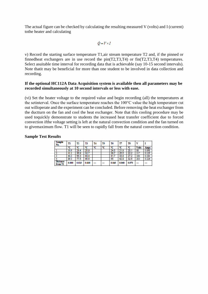
v) Record the starting surface temperature T1,air stream temperature T2 and, if the pinned or
finnedheat exchangers are in use record the pin(T2,T3,T4) or fin(T2,T3,T4) temperatures.
Select asuitable time interval for recording data that is achievable (say 10-15 second intervals).
Note thatit may be beneficial for more than one student to be involved in data collection and
recording.
If the optional HC112A Data Acquisition system is available then all parameters may be
recorded simultaneously at 10 second intervals or less with ease.
(vi) Set the heater voltage to the required value and begin recording (all) the temperatures at
the setinterval. Once the surface temperature reaches the 100°C value the high temperature cut
out willoperate and the experiment can be concluded. Before removing the heat exchanger from
the ductturn on the fan and cool the heat exchanger. Note that this cooling procedure may be
used toquickly demonstrate to students the increased heat transfer coefficient due to forced
convection ifthe voltage setting is left at the natural convection condition and the fan turned on
to givemaximum flow. T1 will be seen to rapidly fall from the natural convection condition.
Sample Test Results

Experiment -8.2
To Demonstrate the Relationship Between Power Input and Surface Temperature in
Forced Convection
Aim of This Experiment
This experiment aim to establis relations between power input and surface temparature changes
during forces convection.
Procedure
undertake steady state experimental procedures within a reasonable time period as the plates
will stabiliserelatively quickly.
The same procedure is utilised for the three types of plate, Flat, Pinned and Finned.
(i) Ensure the instrument console main switch is sin the off position. Ensure the fan is switched
off.
(ii) If the flat (pinned or finned) plate is not in position, open the toggle clamps. Replace with
theflat(pinned or finned) plate and close the toggle clamps. Note that with the plate
heatexchangers the power leads exit from the top of the plates.
(iii) Note that the flat plate will have the minimum blockage effect upon the air stream and
thepinned plate will have the maximum. Hence it will not be possible to achieve the
samemaximum air velocity reading (fan at full speed) with the pinned plate in position as with
theflat plate in position. If direct comparison between finned, pinned and flat plate
performanceis required then it would be beneficial to test the pinned plate first in order to
establish themaximum possible velocity reading U. Then the remaining plates can be tested
under similaror lower air flow conditions.
(iv) Switch on the main switch (1) and set air velocity to a low value by closing the air
throttle(9). Increase the heater power to a suitable level such that ts (T1) does not
exceed100°C.Allow the temperatures to stabilise and then record the surface temperature ts
(T1), theheater supply voltage V , heater current I and the air velocity U.
(v) Maintain the heater voltage at the same condition and then increase the air velocity
byopening the air throttle (9). Once again allow the temperatures to stabilise and repeat
thereadings. Repeat the procedure at increasing air velocity if required.
(vi) For direct comparison repeat the procedure for the three plates under similar heat
inputconditions and at similar velocities.

Sample Test Results

Experiment -8.3
To Demonstrate The use of Extended Surfaces To Improve Heat Transfer From the
Surface.
Aim of This Experiment
This experiment aim to proof importance of using extended surfaces to improve heat transfer
from the surface.
Procedure
The following procedure may be undertaken either in natural convection conditions (fan not
operating)or in forced convection conditions. In both cases the use of extended surfaces does
increase the rate ofheat transfer. However as demonstrated in experiment No 1 the time taken
to achieve stabletemperatures when investigating natural convection can be
considerable.Therefore a forced convection experiment is described as follows.
The same procedure is utilised for the three types of plate, Flat, Pinned and Finned.
(i) Ensure the instrument console main switch is sin the off position. Ensure the fan is
switchedoff. For the natural convection experiments the fan will not be used.
(ii) If the flat (pinned or finned) plate is not in position, open the toggle clamps retaining theplate
in the tunnel and remove the existing plate from the tunnel. Replace with the flat(pinned or
finned) plate and close the toggle clamps. Note that with the plate heat exchangersthe power
leads exit from the top of the plates.
(iii) Note that the flat plate will have the minimum blockage effect upon the air stream and
thepinned plate will have the maximum. Hence it will not be possible to achieve the
samemaximum velocity reading (with the air throttle (9) fully open) with the pinned plate
inposition as with the flat plate in position. If direct comparison between finned, pinned and
flatplate performance is required then it would be beneficial to test the pinned plate first in
orderto establish the maximum possible velocity reading U. Then the remaining plates can
betested under similar or lower air flow conditions.
(iv) Switch on the main switch (1) and set the air speed to a low value by closing the air
throttle
(9). Increase the heater power to a suitable level such that ts (T1) does not exceed100°C.Allow
the temperatures to stabilise and then record the surface temperature ts (T1), airstream
temperature ta (T5), the heater supply voltage V and the air velocity reading U m/s.
(v) Maintain the heater voltage at the same condition and then increase the air velocity
byopening the air throttle (9) Once again allow the temperatures to stabilise and repeat
thereadings. Repeat the procedure at increasing air velocity if required.
(vi) For direct comparison repeat the procedure for the three plates under similar heat
inputconditions and at similar velocities.

Sample Test Results
Theory of Experiments
If a flat surface is heated to a temperature above that of its surroundings heat will be transferred
from it bymeans of convection and radiation. The amount of heat apportioned to each method
of heat loss willdepend upon the temperature of the surface and its emissivity.
Assuming the surface is not at elevated temperatures the majority of heat will be lost due to
convectioncaused by a local increase in buoyancy adjacent to the surface causing an upward
flow. For a simple flatplate the amount of heat lost will be small due to the low heat transfer
coefficient.
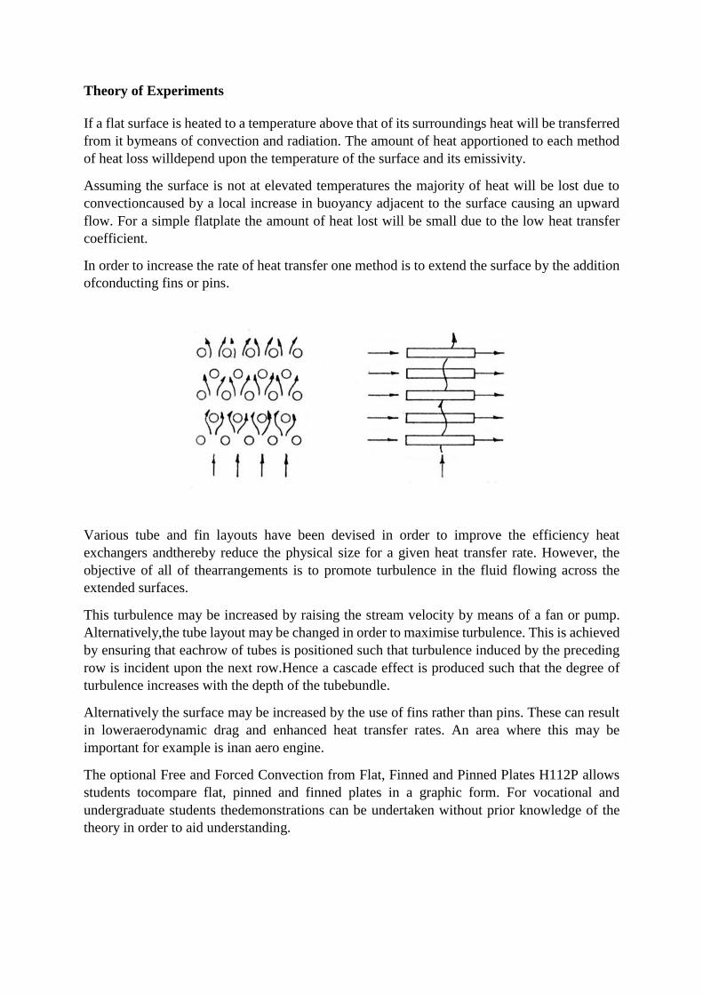
In order to increase the rate of heat transfer one method is to extend the surface by the addition
ofconducting fins or pins.
Various tube and fin layouts have been devised in order to improve the efficiency heat
exchangers andthereby reduce the physical size for a given heat transfer rate. However, the
objective of all of thearrangements is to promote turbulence in the fluid flowing across the
extended surfaces.
This turbulence may be increased by raising the stream velocity by means of a fan or pump.
Alternatively,the tube layout may be changed in order to maximise turbulence. This is achieved
by ensuring that eachrow of tubes is positioned such that turbulence induced by the preceding
row is incident upon the next row.Hence a cascade effect is produced such that the degree of
turbulence increases with the depth of the tubebundle.
Alternatively the surface may be increased by the use of fins rather than pins. These can result
in loweraerodynamic drag and enhanced heat transfer rates. An area where this may be
important for example is inan aero engine.
The optional Free and Forced Convection from Flat, Finned and Pinned Plates H112P allows
students tocompare flat, pinned and finned plates in a graphic form. For vocational and
undergraduate students thedemonstrations can be undertaken without prior knowledge of the
theory in order to aid understanding.

Appendix – I Symbolas and Units

Appendix – II Some Useful Data


![FINNED PIPES CONVECTION HEAT TRANSFER IN EXTERNALLY ... · et al. [4] studied the influence of buoyancy forces on forced convection heat transfer in vertically oriented, externally](https://img.dokumen.tips/doc/110x75/5e6d3620e59fdf3f9c0e33d3/finned-pipes-convection-heat-transfer-in-externally-et-al-4-studied-the-influence.jpg)