Embed Size (px)
Citation preview

Journal of Ship Research, Vol. 55, No. 2, June 2011, pp. 135–147
Experience from SIMMAN 2008—The First Workshop on Verification
and Validation of Ship Maneuvering Simulation Methods
F. Stern,* K. Agdrup,† S.Y. Kim,‡ A.C. Hochbaum,§ K.P. Rhee,k F. Quadvlieg,} P. Perdon,# T. Hino,**R. Broglia,†† and J. Gorski‡‡
*lowa Institute of Hydraulic Research, USA†FORCE Technology, Denmark‡Maritime and Ocean Engineering Research Institute, Korea§Technische Universitat Berlin, GermanykSeoul National University, Korea}Maritime Research Institute Nederlands, The Netherlands#Le Bassin d’essais des carenes, France
**National Maritime Research Institute, Japan††Instituto Nazionale per Studi ed Esperienze di Architettura Navale, Italy‡‡Naval Surface Warfare Center, Carderock Division, USA
The SIMMAN 2008 workshop was held in Copenhagen, Denmark in April 2008. Thepurpose of the workshop was to benchmark the prediction capabilities of different shipmaneuvering simulation methods including systems- and CFD-based methodsthrough systematic quantitative comparisons and validation against EFD data fortanker (KVLCC), container ship (KCS), and surface combatant (5415) hull form testcases. For the KVLCC test case, two stern shape variants named KVLCC1 andKVLCC2 giving different instability loops were included. Free model test data wascompared with systems-based methods and CFD for specified free maneuvers.Some of the systems-based methods used provided PMM and CMT data, and twoused CFD instead. CFD-based methods were used to simulate forced motions andwere compared with PMM/CMT model test data. The submissions were blind in thesense that the benchmark model test data was not provided prior to the workshop,unless data was required as input to the simulation method. A total of 64 submissionswere received for the free maneuver simulations, which included a wide range of thestate-of-the-art methods in use today, such as PMM- and CMT-based methods, CFD-based methods, system identification, neural network tools and various empiricalmethods. For the forced motion simulations a total of 16 submissions were received,comprising different CFD-based methods such as RANS, URANS, and DES. Thispaper gives an overview of hulls, model tests, test cases, submissions, comparisonresults as well as the most important observations and conclusions.
Keywords: maneuvering; model testing
1. Background
THE SIMMAN 2008 workshop was the outgrowth of discus-sions and planning conducted by the 24th and 25th ITTC Maneu-
vering Committees. The workshop was the first of its kindfor several reasons, primarily because maneuvering simulationmethods have yet to be benchmarked for their prediction capabil-ities through systematic quantitative validation against EFD. Thisbenchmarking was conducted for both systems- and CFD-basedmethods. Also, the international collaboration for captive and free
Manuscript received at SNAME headquarters February 9, 2010; revised
manuscript received October 1, 2010.
JUNE 2011 0022-4502/11/5502-0135$00.00/0 JOURNAL OF SHIP RESEARCH 135

model EFD validation data was noteworthy, as it involved11 ITTC institutions and 10 countries from Europe, Asia, andAmerica. An extensive model test campaign was performed foreach of the three hulls, comprising both PMM and CMT tests inappended and bare hull conditions as well as free model tests.Several of the tests were carried out in more than one facility.
Test cases were selected for which the participants shouldmake simulations. A website was used to facilitate the workshoporganization and dissemination of information and instructions toparticipants (www.simman2008.dk). Prior to the workshop, thesubmitted simulation results were compiled and plotted againstthe benchmark data. A general reference is made to the workshopproceedings (Stern & Agdrup 2009) for further details of themethods and the comparison results. The main characteristics are
briefly reported here; for more details the reader should refer toStern & Agdrup (2009).
2. Hulls
The hulls chosen for the workshop were those recommended asbenchmark ships by the 24th ITTC. No full-scale ships exist basedon any of these hull forms.
• KVLCC: The MOERI KVLCC tanker was conceived to pro-vide data for flow physics and CFD validation for a 1997tanker hull form with bulbous bow and transom stern. Twostern variants were designed: KVLCC1 has barge-type sternframe lines with a fine stern end bulb, that is, relativelyV-shaped frame lines, while KVLCC2 has more U-shaped
Nomenclature
X0* ¼ Steady resistance coefficient in X0
from pure sway/pure yaw results
computed by X00 � X02 (Sakamoto
2009, Yoon 2009)
X00 � X0
* ¼ Dynamic increase of resistance
coefficient in X0 from pure sway/pure
yaw
X0vv,2 ¼ Dynamic increase of resistance
coefficient in X0 from pure sway/pure
yaw
Y0vdot,N0
vdot
¼ Linear hydrodynamic derivative in
Y0 and N0 w.r.t n from pure sway
Y0v, N0v ¼ Linear hydrodynamic derivative in
Y0 and N0 w.r.t _n from static drift/
first-harmonic of pure sway
Y0vvv,3,N0
vvv,3
¼ Nonlinear hydrodynamic derivative
in Y0 and N0 w.r.t n from third-
harmonic of pure sway
Y0d, N0d ¼ Linear hydrodynamic derivative in
Y0 and N0 w.r.t d for static rudder
wY, wN
(deg)
¼ Phase angle w.r.t Y0 and N0 (Yoon2009). For pure sway,
wY = tan�1(Yv/Yvv). For pure yaw,
wY = tan�1 (Yr/Yrv). v: sway/yaw
motion frequency, same for wN.
N0v/Y
0v ¼ Stabilizing arm
N0d/Y
0d ¼ Rudder moment arm
X0rr,2 ¼ Nonlinear hydrodynamic derivative
in X0 w.r.t r from second harmonic of
pure yaw result
Y0rdot,N0
rdot
¼ Linear hydrodynamic derivative in Y0
and N0 w.r.t _r from pure yaw result
Y0r, N0r ¼ Linear hydrodynamic derivative in Y0
and N0 w.r.t r from static drift/first
harmonic of pure yaw
Y0rrr,3,N0
rrr,3
¼ Nonlinear hydrodynamic derivative
in Y0 and N0 w.r.t r from third
harmonic of pure yaw result
(N0r�m0xG)/(Y0r�m0)�N0
v/Y0v
¼ Stability arm�E%D ¼ Comparison error of forces and
moment coefficients from
static tests, and/or hydrodynamic
derivatives from static/dynamic tests,
(D � S)/D + 100, D, EFD data; S,
CFD result
ðj �EjÞ %D ¼ Average E of hydrodynamic
derivatives among different
organizations�EX0Y0N0 %
D¼ Average E of forces and moment
coefficients over 1 sway/yaw period,
D � S/D + 100
EREFD %
D
¼ Average reconstruction E of forces
and moment coefficients over 1
sway/yaw period, Doriginal �Dreconstructed=jDoriginalj + 100
ERCFD %
D
¼ Average reconstruction E of forces
and moment coefficients over 1
sway/yaw period, Doriginal �Sreconstructed=jDoriginalj + 100
�Eave %D ¼ Average of �EX0Y0N0 %D or
EREFD, RCFD %D over X0, Y0,and N0
Acronyms
BEC ¼ Le Bassin d’essais des carenes,
France
BEM ¼ Boundary element model
BSHC ¼ Bulgarian Ship Hydrodynamic
Center, Bulgaria
CEHIPAR ¼ Canal de Experiencias
Hidrodinamicas, El Pardo, Spain
CFD ¼ Computational fluid dynamics
CMT ¼ Circular motion tests
CTO ¼ Ship Hydrodynamics Division,
Centrum Techniki Okretowej,
Poland
DES ¼ Detached eddy simulations
EFD ¼ Experimental fluid dynamics
FORCE ¼ FORCE Technology, Denmark
HSVA ¼ Hamburgische Schiffbau-
Versuchsanstalt GmbH, Germany
IHI ¼ Hokkaido University, Japan
IIHR ¼ Iowa Institute of Hydraulic
Research, USA
INSEAN ¼ Instituto Nazionale per Studi ed
Esperienze di Architettura Navale,
Italy
ITTC ¼ International Towing Tank
Conference
LAMP ¼ Open source software stack (based
on Linux, Apache, MySQL, and
PHP)
MARIN ¼ Maritime Research Institute
Nederlands, The Netherlands
MMG ¼ Mathematical Model Group
(Japan)
MOERI ¼ Maritime and Ocean Engineering
Research Institute, Korea
NMRI ¼ National Maritime Research
Institute, Japan
NSWC ¼ Naval Surface Warfare Center,
Carderock Division, USA (formerly
DTMB)
PIV ¼ Particle-induced velocimetry
PMM ¼ Planar motion mechanism
SAIC ¼ Science Applications International
Corporation, USA
SNU ¼ Seoul National University, Korea
SVAP ¼ Schiffbau-Versuchsanstalt Potsdam
GmbH, Germany
(U)RANS ¼ (Unsteady) Reynolds averaged
Navier-Stokes calculations
136 JUNE 2011 JOURNAL OF SHIP RESEARCH
stern frame lines. The main particulars of the two hull ver-sions are given in Table 1.
• KCS: The MOERI Container Ship KCS is a fairly modern(1997) container ship with bulbous bow and transom stern.The main particulars of the KCS are given in Table 1.
• 5415: The DTMB 5415 was conceived as a preliminarydesign for a 1980 Navy surface combatant. The hull geome-try includes both a sonar dome and transom stern. Propulsionis provided through twin open-water propellers driven byshafts supported by struts. The main particulars of the 5415are given in Table 1. Further details of all three models aregiven in Stern and Agdrup (2009).
3. Model tests
Models of the two KVLCC variants have been built first byMOERI in 1999 to the scale of 1:58.00 and tested in the PMM atMOERI. In 2006 NMRI manufactured a set of models to the scaleof 1:110.00 for CMT tests, and finally INSEAN built a set ofmodels to the scale of 1:45.71 also in 2006. The latter modelshave been tested in the PMM at INSEAN and then transported toHSVA, CTO, and MARIN for free model tests.
A model of the KCS was first built by MOERI in 1999 to thescale of 1:31.60; however, the tests with this model were not partof the present workshop. NMRI manufactured a model to the scaleof 1:75.50 and conducted CMT tests in 2005. The PMM tests atCEHIPAR and the free model tests at SVA and BSHC have beenperformed with the model built by SVA in 2006 to the scale of1:52.67.
A model of the 5415 was built by MARIN in 2000 to the scaleof 1:35.48 and used for free model tests. This model wastransported to FORCE for PMM tests later that year. In 2004 theappendages were removed in order to perform bare hull PMMtests including uncertainty assessment at FORCE and later rotat-ing arm tests at BEC. Bare hull PMM tests have also beenperformed at IIHR with a smaller model (1:46.59) including PIVand at INSEAN with a larger model (1:24.83). All bare hull testshave been carried out without rudders and propeller arrangement,but with bilge keels and a skeg of a somewhat different designthan in the appended hull tests at MARIN and FORCE.
An overview of all performed model tests is given in Table 2. Itshould be noted that even with the extensive test campaign thathas been performed including several overlapping test series,there are still unresolved issues with parts of the benchmark data.For instance, some of the captive tests were carried out at condi-tions different to those of the free model tests in terms of RPMstrategy, while some of the free model tests were done atnonstationary initial conditions or using a different helm rate thanthe nominal value. These deviations are partly due to the fact thatsome of the test series were performed before starting to plan theworkshop around 2003 to 2005. This has made the evaluation ofthe comparisons difficult in some cases.
4. Test cases
Test cases were selected for the participants to make simula-tions following detailed instructions given on the workshopwebsite. One set of test cases consisted of most representativeforced motions selected from the captive model tests. These wereto be simulated using CFD-based methods, see Table 3.
Another set of test cases were traditional free maneuvers asmandated by IMO such as the 35 deg turning circle and the 10/10and 20/20 zig-zag tests, for which all simulation methods couldbe used. These test cases were to be validated by comparisonwith the free model tests and are summarized in Table 4. It
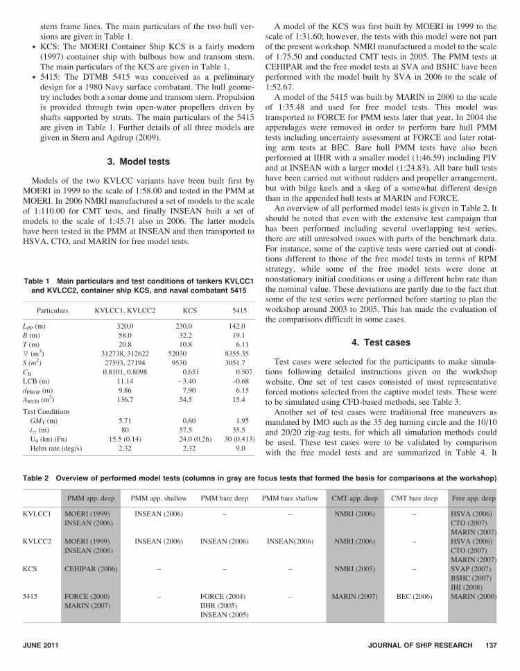
Table 1 Main particulars and test conditions of tankers KVLCC1and KVLCC2, container ship KCS, and naval combatant 5415
Particulars KVLCC1, KVLCC2 KCS 5415
LPP (m) 320.0 230.0 142.0
B (m) 58.0 32.2 19.1
T (m) 20.8 10.8 6.11
▽ (m3) 312738, 312622 52030 8355.35
S (m2) 27593, 27194 9530 3051.7
CB 0.8101, 0.8098 0.651 0.507
LCB (m) 11.14 �3.40 –0.68
dPROP (m) 9.86 7.90 6.15
ARUD (m2) 136.7 54.5 15.4
Test Conditions
GMT (m) 5.71 0.60 1.95
izz (m) 80 57.5 35.5
U0 (kn) (Fn) 15.5 (0.14) 24.0 (0.26) 30 (0.413)
Helm rate (deg/s) 2.32 2.32 9.0
Table 2 Overview of performed model tests (columns in gray are focus tests that formed the basis for comparisons at the workshop)
PMM app. deep PMM app. shallow PMM bare deep PMM bare shallow CMT app. deep CMT bare deep Free app. deep
KVLCC1 MOERI (1999)
INSEAN (2006)
INSEAN (2006) – – NMRI (2006) – HSVA (2006)
CTO (2007)
MARIN (2007)
KVLCC2 MOERI (1999)
INSEAN (2006)
INSEAN (2006) INSEAN (2006) INSEAN(2006) NMRI (2006) – HSVA (2006)
CTO (2007)
MARIN (2007)
KCS CEHIPAR (2006) – – – NMRI (2005) – SVAP (2007)
BSHC (2007)
IHI (2008)
5415 FORCE (2000)
MARIN (2007)
– FORCE (2004)
IIHR (2005)
INSEAN (2005)
– MARIN (2007) BEC (2006) MARIN (2000)
JUNE 2011 JOURNAL OF SHIP RESEARCH 137

should be noted that all the free model tests to be used as bench-mark were done at constant RPM; however, since some of thecaptive tests to be used as input data had already been done usinga constant torque strategy, these conditions were included asoptional test cases.
5. Results from simulations of forced motionsby CFD
The focus of the CFD-based methods portion of the workshopwas on PMM-type forced motions such as static rudder, static driftas well as pure sway and pure yaw. In addition, two of the CFD-based methods provided results for zigzag and turning circlemaneuvers.
5.1. Submissions and codes
The submissions for the CFD part of the workshop included13 ITTC institutions from 10 countries for appendedKVLCC1&2 (9 submissions), appended KCS (2 submissions)and bare/appended 5415 (5 submissions). Nine different com-mercial/in-house URANS solvers were used. Turbulence was
modeled by 1- and 2-equation isotropic/anisotropic models andReynolds-stress transport model. Free surface was mostlymodeled by a surface capturing method (e.g., level-set, volumeof fluid), and only one institution used surface trackingapproach. For the propeller modeling, body-force model andBEM methods were used by most participants. For numericalmethods, spatial discretization was done by finite difference andfinite volume methods with structured/unstructured grids forwhich the average number of grid points was 5.1M. The orderof accuracy in time integration was mostly second-order orhigher. The divergence-free condition was satisfied either byvelocity-pressure correction or an artificial compressibilityapproach. Analytical weighted regridding, mesh morphing, anddynamic overset approaches were used to handle dynamic shipmotions. For the high-performance computing, message passinginterface (MPI) or open MP were used in many cases as aparallel computing technique. Multigrid technique was also usedby one organization for speeding up computations. Very fewparticipants showed verification and validation (V&V) results,that is, verification by one institution for KVLCC2, and V&Vby one institution for 5415 bare hull, both following the V&Vmethod proposed in Stern et al. (2001).
5.2. Comparison with model tests
Comparisons were made between EFD and CFD for originalvalues of X0, Y0, and N0, slope of forces and moments versusdynamic variables referred to as linear hydrodynamic derivatives,higher-order terms of the slope referred to as nonlinear hydrody-namic derivatives, and reconstructed values following a third-order Taylor series Abkowitz-type model (Abkowitz 1964). Thereaders are referred to Sakamoto (2009) and Yoon (2009) fordetailed derivation of the hydrodynamic derivatives and recon-structions. The nomenclature and variable definitions used in theanalysis of the results in CFD-based maneuvering predictionmethod are shown in the table at the beginning of this article. Itmust be noted that: (1) the present comparisons are only for arepresentative subset of the captive model tests required to derivea complete set of hydrodynamic derivatives as input to systems-based maneuvering predictions, (2) in some cases linear curve fitsfor static maneuvers and single-run methods for dynamic maneu-vers show the difference of common hydrodynamic derivatives,and (3) differences between original values X0, Y0, and N0 andreconstructions are due both to limitations of the mathematicalmodel and linear curve fits for static maneuvers and single-runmethods for dynamic maneuvers.
5.2.1. Definitions. The comparison error E for nondimensionalforces and yaw moment from static PMM tests and for hydrody-namic derivatives from both static and dynamic PMM tests isdefined as:
Eð%DÞ ¼ D� S
D· 100 ð1Þ
where D is the experimental data and S the computational result.For the forces and moment coefficients from dynamic PMMtests, it is difficult to apply equation (1) since the profile of Y andN cross 0 at certain planar motion phases. To avoid this, theaverage comparison error EX0, Y0, N0 is defined over 1 planar motionperiod as:
Table 3 Test cases for simulation of forced motions
Hull Simulation conditions Test type Test condition
KVLCC1, KVLCC2 Appended Heave and
pitch free; roll fixed
Static rudder d = 0, 10 deg
Static drift b = 12 deg
Pure sway v0 = 0.0852
Pure yaw r0 = 0.30
KCS Appended Heave and
pitch free; roll fixed
Static rudder d = 0, 10 deg
Static drift b = 8�
Pure sway v0 = 0.140
Pure yaw r0 = 0.40
5415 Bare hull fixed Static drift b = 10 deg
Pure sway v0 = 0.174
Pure yaw r0 = 0.30
Appended heave and
pitch free; roll fixed
Static drift b = 10 deg
Pure sway v0 = 0.174
Pure yaw r0 = 0.410
Table 4 Test cases for simulation of free maneuvers
Hull Test type Approach speed Helm rate
KVLCC1, KVLCC2 10/10 zig-zag 15.5 kn 2.32 deg/s
20/20 zig-zag
5, 10, 20, 35 deg
turning circle
KCS 10/10 zig-zag 24.0 kn 2.32 deg/s
20/20 zig-zag
5, 10, 20, 35 deg
turning circle
5415 10/10 zig-zag 30.0 kn
(optional: 18.0 kn)
9.0 deg/s
20/20 zig-zag
5, 10, 20, 35 deg
turning circle
138 JUNE 2011 JOURNAL OF SHIP RESEARCH

�EX0; Y0;N0 ð% Dj jÞ ¼ 1=N(N
i Di � Sij j1=N(
N
i Dij j· 100 ð2Þ
where N is the total number of experimental data points, Di is theinstantaneous experimental data, and Si is the instantaneous com-putational result. To match the instantaneous time between thecomputational result and the experimental data, the computationalresults are subjected to cubic spline interpolation before the erroris calculated. The average reconstruction error for the experimen-tal data ER(EFD) is defined following a similar manner, where Si isreplaced by DRi, the instantaneous reconstructed experimentaldata. The average comparison error between the reconstructedcomputational result and the original experimental data ER(CFD) isalso defined using equation (2) where Si is replaced by DRi, theinstantaneous reconstructed computational result. The total aver-age comparison error Eave for all forces is defined as:
�Eave ¼�EX0 þ �EY0 þ �EN0
3ð3Þ
5.2.2. Results. In the straight ahead hull with rudder tests, the Xerror was larger than expected. The large Y and N errors were notconsidered critical, since the nonzero side force and yaw momentare very small, being solely due to the effects of asymmetricrudder/propeller/hull interaction and thus also difficult to measureaccurately. Subtracting the propeller thrust (T), the error in X-Twas smaller than for X, which perhaps is because T was prescribedbased on EFD in the simulations. The straight ahead hull withstatic rudder X, Y, and N errors were smaller, indicating that CFDperforms better in predicting the relatively large global side forceand yaw moment than for the local rudder forces. However, the Nand especially Y errors were relatively larger than expected, forinstance for the case with 10 deg rudder angle for KVLCC2,shown in Fig. 1. The errors for the rudder forces were also largewith the largest errors for the rudder side force RY. This deviationcould be due to insufficient grid resolution, the used turbulencemodel, or perhaps more importantly, an inadequate propellermodel, the rudder being located in its slipstream. The static driftcase showed relatively small errors for X, Y, and N of about 11%D, see results for KVLCC2 on Fig. 2. The largest errors were forX, N, and RX. In this case the errors for X-T were larger than for X.The errors for the rudder forces were larger than that for zero driftangle. In most cases, the errors for the bare hull were less thanthose for the appended (propelled) condition. The errors for thelinear hydrodynamic derivatives were relatively small for the hulland large for the rudder.
The predictions of hull and rudder forces for KVLCC1&2 inpure sway showed overall agreement for Y and N as shown inFig. 3. The side force and yaw moment are dominated by thepressure component, giving a better agreement than X, which isdominated by the viscous component. This is similar to what wasobserved for the static tests. For KVLCC2 the errors for X, Y, andN averaged over all submissions were 14%D. The large discrep-ancy in X for hull and rudder is likely due to insufficient gridresolution and inaccuracy of either turbulence model or pro-peller model. The errors for linear and nonlinear maneuveringderivatives averaged over all submissions were 6%D and 70%D,respectively. The CFD reconstruction error averaged over all
submissions was 12%D, that is, similar magnitude as the errorsfor X, Y, and N. In consideration of the 5%D error for the EFDreconstruction, 6% to 14%D errors in CFD for forces, moments,and linear hydrodynamic derivative; CFD seems promisingas a replacement for pure sway test at least up to present maxi-mum sway amplitude. Although the nonlinear hydrodynamicderivatives are quite large, but are less important for the evalua-tion of CFD predictions compared with linear hydrodynamicderivatives especially for present moderate angle of attack. In pureyaw, the overall agreement in prediction of forces and momentwere less satisfactory compared with that observed for pure sway.This is shown in Tables 5 and 6, where the errors for hydrody-namic forces and hydrodynamic derivatives have been calculatedfor KVLCC2 in pure yaw. Errors for forces and hydrodynamicderivatives were about 2 and 5 times larger, respectively, than for
Fig. 2 KVLCC2 static drift. b = 10 deg, side force, yaw moment, and
rudder forces from different CFD codes compared with experimental results
Fig. 1 KVLCC2 static rudder. d = 10 deg, side force, yaw moment, and
rudder forces from different CFD codes compared with experimental results
JUNE 2011 JOURNAL OF SHIP RESEARCH 139

pure sway. CFD and EFD reconstruction errors are about 2 timeslarger than for pure sway. It seems that additional verification andvalidation is required for pure yaw.
For KCS in pure sway and pure yaw, the overall trends weresimilar to what was observed for KVLCC. However, the experi-mental results for pure yaw are probably unreliable. Therefore,additional PMM tests including uncertainty analysis have beeninitiated recently at FORCE.
For 5415 in bare and appended hull conditions the overalltrends in the predictions were similar to what was observed forKVLCC and KCS. Both for bare hull pure sway and pure yawthe errors were relatively small for linear hydrodynamic deriva-tives, but large for nonlinear derivatives. Pure sway X, Y, and Nand CFD reconstruction errors were 15%D and EFD reconstruc-
tion error was 6%D; pure yaw X, Y, and N and CFD reconstruc-tion errors were 20%D and EFD reconstruction error was 4%D.Pure yaw computational results showed a phase lag with respectto the experimental data, which makes the comparison of forcesand moment less satisfactory compared with pure sway. For theappended hull the comparison errors in forces, moment andhydrodynamic derivatives were generally larger than those forbare hull.
The local flow field of 5415 bare hull was subjected to compar-ison with the PIV measurement data, see Fig. 4. The results gen-erally showed good agreement, except that the quantities at vortexcore/off-body in the computational results were underestimated,probably because of insufficient grid resolution and limitations ofthe turbulence model.
Fig. 3 Nondimensional forces and yaw moment from pure sway for KVLCC2 shown as (a) original and (b) reconstructed time series, CFD results
compared with model test results
140 JUNE 2011 JOURNAL OF SHIP RESEARCH

Looking at the test cases for all hulls together as summarized inTable 7, the errors for both forces, hydrodynamic derivatives, andreconstructions averaged over all submissions seem to increasewith the complexity of the motion: X, Y, and N errors increasedfrom 11%D over 19%D to 30%D when going from static driftover pure sway to pure yaw. In general, X errors were larger thanY and N errors. Linear hydrodynamic derivative errors increasedfrom 8%D to 23%D from pure sway to pure yaw. CFD reconstruc-tion errors increased from 20%D to 31%D from pure sway topure yaw. Similarly, EFD reconstruction errors increased from9%D to 13%D from pure sway to pure yaw. The errors for thelinear course stability index (C) averaged over all submissionswere 15% (KVLCC1), 30% (KVLCC2), 5% (5415 bare hull),and 75% (5415 appended hull).
6. Results from simulations of free maneuvers
6.1. Submissions and methods
The number of received submissions for free maneuver simula-tions was large, namely 22 for KVLCC1, 21 for KVLCC2, 11 forKCS, and 10 for 5415, 64 in total. There was a wide variation ofmethods being used, ranging from PMM- and CMT-basedmethods, over system identification and neural network tools, toCFD-based methods and various empirical methods. The term“empirical” is used here to denote methods that are based on datafrom other ships using for instance a statistical approach, that is,not based on model tests or calculations for the specific ship.
Figure 5 gives an overview of all submissions that were madefor free turning circle maneuvers to portside for the KVLCC1.Figure 5 shows the predicted trajectories of all methods up to aheading change of 360 deg. The objective of this figure is not tocompare all difference methods to each other, but to give anoverview of the scatter that is found. To increase the insight, themethods are divided into five groups:
• Empirical/semiempirical methods (EMP)• Methods based on RANS or DES (CFD)• Methods based on PMM tests (PMM)• Methods based on CMT tests (CMT)• Results from free model tests (FREE).
This scatter of the different predictions can be the result of thedifferent nature of the methods including the applied mathemati-
cal model and the number of degrees of freedom (roll included ornot), as well as caused by the applied propeller conditions. Thisconcerns both whether model or ship self-propulsion point (SPP)was used and whether the RPM was kept constant throughout thesimulation or regulated following a constant torque strategy.
Each of the four first groups have been analyzed separately,using the free model test results as reference for the comparisons.
6.2. Comparison with free model tests
6.2.1. KVLCC. The free model tests revealed that the differencein maneuvering characteristics between the two versions of theKVLCC was smaller than anticipated, when these hulls wereselected for the workshop. For instance, the tests done at MARINindicated that the difference in the first overshoot angle in the10/10 zig-zag test was less between KVLCC1 and KVLCC2(0.4 deg) than between two subsequent tests performed with initialturn to opposite sides (1.5 deg). The corresponding tests done atHSVA showed somewhat larger difference between the two hullversions (1.9/4.2 deg for initial turn to SB/PS), but part of thisdifference was caused by running the two test series using differ-ent definitions of “zero rudder angle,” one being the geomet-rical and another being the neutral rudder angle. With thisbackground—and with the mentioned scatter of the submittedresults—the main focus of the analysis at the workshop was onthe actual predictions for each hull, rather than on the predictionof the difference between the two hull versions.
The simulation results for the tactical diameter of the 35 degturning circle are shown for all KVLCC1 submissions in Fig. 6.Five of these submissions were based on PMM tests, one of themon the INSEAN tests, and the rest on the MOERI tests. Oneinstitute (FORCE) made simulations from both sets of PMMdata, using the same 3 DOF mathematical model. The FORCEresults showed a larger tactical diameter (and smaller overshootangles) for the simulations based on the INSEAN data than forthe MOERI data. This difference can only partly be explained bythe fact that the INSEAN tests were performed at model SPP andat constant torque, while the MOERI tests were done at ship SPPand constant RPM.
Looking at the four submissions based on the MOERI tests, twoof these (SNU and MOERI) used a modular MMG-type (Kijima &Nakiri 2003) mathematical model and the other two used a “whole-ship” Abkowitz-type (Abkowitz 1964) mathematical model. Themean value of the tactical diameter predicted by these four sub-missions correlated well with the mean of the free model testresults, the error being 5.3% for the starboard turning circle. How-ever, the scatter was substantial with an RMS value of 9.7%, possi-bly connected with the different mathematical models. Here, as wellas in other cases, the RMS error is significantly larger than the meanerror, which implies that conclusions should not be drawn based onthe mean error only.
The overall picture from the comparison of the PMM-basedmethods was that there seems to be a “residual deviation” that thementioned differences cannot explain, but which could be attrib-uted to the degree of control over the consistency between themodel test data and the applied mathematical model. In otherwords, it seems that “homegrown methods” perform best.
Comparing the three CMT-based submissions to the benchmarkfree model data, the correlation was somewhat better than for thePMM-based submissions: a mean error of 2.7% and an RMS of
Table 5 Average error (%D) between original/reconstructed CFDresults and original EFD data from pure yaw for KVLCC2
Org. Code Error �E �ERðCFDÞ �ERðEFDÞ
HSVA NepIII �EX0 32.2 32.8 –�EY0 30.4 29.7 –�EN0 11.8 9.5 –�Eave 24.8 24.0 –
INSEAN Xnavis �EX0 30.2 33.7 32.8�EY0 29.4 29.6 7.1�EN0 21.5 21.9 4.5�Eave 27.0 28.4 14.8
MOERI Wavis �EX0 43.8 40.3 –�EY0 22.8 20.8 –�EN0 19.4 20.4 –�Eave 28.7 27.2 –
JUNE 2011 JOURNAL OF SHIP RESEARCH 141

7.4% for the portside turning circle. Nevertheless, this scatter isstill relatively large, considering the fact that all three submissionswere based on the same set of model test data (NMRI) and allhave used an MMG-type model.
As for the empirical methods, a very large scatter wasobserved: RMS of 23.1% with a mean error of 16.1% for theport turn. However, behind these overall figures were both anumber of empirical methods that performed relatively well(Marintek_SIMAN, MARIN_MPP, and FORCE_SY) as well asa number of outliers that apparently are not normally applied forthis ship type (MARIN_Kijima, _FRESIM, and _SURSIM).
Three institutes submitted CFD-based simulations for the turn-ing circle of KVLCC1. HSVA_NepIII was a full numericalPMM test using RANS, MARIN_RANS consisted of a partialset of numerical CMT tests combined with empirical ruddercoefficients, and IIHR_DES was a fully free sailing simulationof the first quarter of the turning circle including the rotatingpropeller. The latter gave a reasonable prediction of the advance:2.73Lpp compared with a mean value of 3.01Lpp in the free modeltests. The two first “captive” simulations gave predictions of thetactical diameter with a mean error of 14.8% for the port turn. It isworth noting that the full RANS method gave an error of only
Table 6 Hydrodynamic derivatives from pure yaw for KVLCC2 derived from different CFD codes
MOERI
HSVA INSEAN MOERI
Ave. errorNep III Xnavis Wavis
EFD CFD E (%) CFD E (%) CFD E (%) �Ej j (%)
X0* �0.0221 �0.0222 �0.5 �0.0195 11.8 �0.0245 �10.9 7.7
X00 � X0
* (%X0) �1.74 �1.43 17.8 �1.76 �1.2 18.24 1,148.3 389.1
X0rr 0.0084 0.0071 15.5 0.0077 8.3 �0.0840 1,100.0 374.6
Y0rdot �0.0319 �0.0127 60.2 �0.0189 40.8 �0.0258 19.2 40.0
Y0r 0.0884 0.0698 21.0 0.0067 92.4 0.0688 22.2 45.2
wY (deg) 65.06 76.80 �18.1 15.38 76.4 64.20 1.3 31.9
Y0rrr 0.0090 0.0800 �788.9 �0.0283 414.4 0.0247 �174.4 459.3
N0rdot �0.0101 �0.0095 5.9 �0.0089 11.9 �0.0105 �4.0 7.3
N0r �0.0553 �0.0510 7.8 �0.0422 23.7 �0.0443 19.9 17.1
wN (deg) �76.75 �76.50 0.3 �74.79 2.6 �73.01 4.9 2.4
N0rrr �0.0513 �0.0397 22.6 �0.0598 �16.6 �0.0346 32.6 23.9
(Nr � m0xG)/(Y0r � m0) 0.3193 0.2736 14.3 0.1827 42.8 0.2425 24.1 27.1
N0v/Y
0v � (N0
r � mxG)/(Y0r � m) 0.2259 0.2056 9.0 0.3603 �59.5 0.2712 �20.1 29.5
Fig. 4 5415 bare hull, pure sway, axial velocity contours, and cross-flow vectors in nominal-wake plane at four distinct phase angles of the PMM
cycle for different CFD-based methods, compared with PIV measurements (IIHR PMM and PIV)
142 JUNE 2011 JOURNAL OF SHIP RESEARCH

about 5%, that is, achieving the same level of accuracy as themodel test based methods.
The observations that were made from the comparisons of thesimulated zig-zag tests were similar to those for the turningcircles. Also for the zig-zag tests the scatter in the results wassubstantial.
6.2.2. KCS. Three sets of free model tests were carried out withthe KCS model: at BSHC, at SVA, and at Hokkaido University(IHI); however, all three series with certain deviations from thenominal test conditions. The tank at BSHC imposed a limiteddistance for the acceleration phase, causing the initial releaseconditions to be biased including the approach speed being lessthan the nominal 24 knots. Nevertheless, the tests showed goodrepeatability. At SVA the tests were performed at a rudder rate of9 deg/s instead of the nominal 2.32 deg/s in order to accomplishthe zig-zag tests within the width of the tank. The Hokkaido testswere done after the workshop, differing in the approach speed(18.6 kn) and in the GMT-value, which was 5.1 m instead of thenominal 0.6 m, thereby suppressing the roll motion. Therefore,
these tests were most suitable for comparison with the methodsusing 3 DOF.
The number of submissions for KCS was less than for KVLCC:11 submissions consisting of 4 CMT-based methods and 7 empir-ical methods. Despite PMM test data being made available byCEHIPAR, there were no submissions of free maneuver predic-tions using this data. Also there were no submissions using CFD-based methods.
The scatter of the submitted results was substantial, whichwas especially evident for the second overshoot angle in the10/10 zig-zag test, as shown in Fig. 7. As opposed to theKVLCC having a high GMT, the inclusion of the fourth DOFplays an important role for the KCS. This is clear from compar-ing the four CMT submissions that were all based on an MMGmathematical model using the same set of model test data fromNMRI, but where the Hiroshima submission included the effectof roll using an empirical method. The first three fell closelytogether with an RMS value of 2.1 deg and a mean value of9.5 deg, that is, 2.2 deg (18%) below the benchmark testsperformed at Hokkaido, while the latter method gave higher
Table 7 Summary of simulations of forced motions by CFD
Cases Geometry EX%D EY%D EN%D
Linear
Maneuvering
Derivative
Nonlinear
Maneuvering
Derivative
%D
Reconstruction Errors
Y0%D N0%D ERCFD,X %D ERCFD,Y,N %D EREFD,X %D EREFD,Y,N %D
Static
rudder,
d = 10 deg,
b = 0 deg
KVLCC1 3.47 59.74 �21.27 10–20 60
KVLCC2 50.8 50.1 �36.5 14 58
Average 27 55 �29 14.5 59
Static drift KVLCC1,
b = 0 deg
14.58 – – 10–20 60
KVLCC1,
b = 12 deg
�14.39 �7.23 �11.91
KVLCC2,
b = 0 deg
19.3 – – 14 58
KVLCC2,
b = 12 deg
23.1 2.6 11.6
5415, b = 10� �14.31 4.05 8.94
5415 appended,
b = 10 deg
�23.05 �14.44 11.90
Average 18.1 7.0 10.1 14.5 59
Pure sway KVLCC1 22 10 10 7.7 7.7 65 22 11.6 26 12
KVLCC2 18.6 11.3 11.3 5.8 5.8 75 18.6 11 2 7
KCS 9.26 4.31 92.62 25.0 4.04 19.0
5415 bare 23.6 9.7 9.7 6.9 6.9 30 22.3 10 6 6
5415 appended 21 30.5 30.5 15 15 25 23 31.5 2 13
Average 21.3 15.4 15.4 8 8 49 21.6 15.9 8.5 9.5
Pure yaw KVLCC1 38.3 20 20 19 19 50 38.7 19.3 36 7
KVLCC2 35.3 22.3 22.3 18 18 24 35.7 22.3 33 6
KCS 103.9 36.03 14.46 65.2 10.77 22.0
5415 bare 20.5 21 21 16 16 – 31 20.5 5 3
5415 appended 37 40 40 38 38 22 30 40 3 7
Average 32.8 25.7 25.7 23 23 32 35.4 25.5 19.25 5.75
JUNE 2011 JOURNAL OF SHIP RESEARCH 143

Fig. 6 Tactical diameter derived from �35 deg turning circle simulations with KVLCC1, comparison of all submissions
Fig. 5 KVLCC1 simulations of 35 deg turning circle to port side
144 JUNE 2011 JOURNAL OF SHIP RESEARCH

overshoot angles, closer to the SVA and BSHC tests with amean value of 24.0 deg, that is, 4.2 deg (21%) above theseresults. The empirical methods showed a very large scatter inthe predicted overshoot angles, the four DOF methods giving anRMS value of 8.4 deg with a mean value 5.7 deg (29%) belowthe benchmark. This indicates that a number of these methodswere used outside their regime of applicability. It should benoted that the high degree of scatter demonstrated here for thesecond overshoot angle in the 10/10 zig-zag test was less pro-nounced for most other parameters.
6.2.3. 5415. For the 5415 naval surface combatant the bench-mark free model tests at MARIN and the appended hull PMMtests were carried out for each of the approach speeds 18 and 30knots, the latter being the primary test case. The 10 receivedsimulations for the 30 knots case consisted of 2 PMM-basedmethods (FORCE and SAIC), 6 different empirical codes (allMARIN), and 2 CFD submissions (IIHR using a URANSmethod for both constant RPM and constant torque). A fewsimulation results were also received for the 18 knots case,namely one CFD (IIHR) and one system identification method(NSWCCD using a neural network technique)—the only sub-mission of this type at the workshop. An extract of the repre-sentative results for the 30 knots case are given in Fig. 8, wherethe tactical diameter derived from all 35 deg turning circlesimulations with 5415 are shown.
Of the two PMM-based methods, FORCE used a dedicatedAbkowitz-type mathematical model, while SAIC used the PMMdata to tune the LAMP code (Lin et al. 2006). Both methods wereseen to correlate reasonably well with the free model test results,the mean error being 11.5%. The two applications of the RANS-method from IIHR showed good correlation with the benchmarkdata with an error of 4.4% for the starboard tactical diameter atconstant RPM (as used in the free model tests). For the six empir-ical codes a large scatter was seen; as for the KVLCC and KCSthis was partly due to the decision by MARIN of testing allavailable methods for all hulls in the workshop, irrespective ofship type. In this case the two methods named SURSIM(_SB) arenot normally applied for a frigate-type hull, whereas the threemethods named FRESIM(_SB) and FREDYN are especiallysuited for such a vessel. For these three methods the mean errorwas 0.6Lpp or 12.5% below the benchmark data.
In addition to the standard zig-zag and turning circle maneu-vers, a number of participants submitted simulation results foradditional turning circle tests at multiple rudder angles, namely�5, 10, 20, as well as 35 deg. An analysis of the derived parame-ters, such as yaw rate, drift angle, and speed loss in the steady partof the turning circle, shows that these parameters collapse ratherwell. This is shown in Fig. 9, where selected steady turning valuesare given for five different methods. This indicates that theobserved deviations between the different methods originatemainly from the initial transient part of the maneuvers.
Fig. 7 Second overshoot angle in 10/10 zig-zag simulations with KCS, comparison of all submissions
JUNE 2011 JOURNAL OF SHIP RESEARCH 145

Fig. 8 Tactical diameter derived from �35 deg turning circle simulations with 5415, comparison of all submissions
Fig. 9 Steady turning parameters from simulations of �5, 10, 20, and 35 deg turning circles 5415, transverse velocity (v 0) against yaw rate (r 0)
146 JUNE 2011 JOURNAL OF SHIP RESEARCH
7. CONCLUSIONS
7.1. Simulation of forced motions by CFD
The overall results from the comparisons suggest that finergrids, more advanced turbulence and propeller models, andadditional verification and validation including local flow vari-ables/measurements are required for improvements in the CFDpredictions of static and dynamic PMM maneuvers. Finer gridsare especially needed for the rudder and appendages and inregions of large vorticity. More accurate propeller modeling isdesirable as is the use of free surface capturing methods.
More recently (Sakamoto 2009, Yoon 2009), it has been shownthat multiple-run CFD/EFD curve fitting methods can providebetter estimates for nonlinear maneuvering derivatives than thesingle-run method used here, but statistical convergence of thehigher-order Fourier series components is an issue. Recent results(Stern et al. 2009) for 5415 bare hull 20 deg static drift using 10 to250M grid points and DES turbulence modeling have shown thaterrors in X, Y, and N can be reduced to less than 5%D, which iscomparable to errors for straight ahead resistance at the Gothen-burg 2000 and Tokyo 2005 CFD workshops.
In consideration of the reasonable errors observed for bothforces, linear maneuvering derivatives and CFD reconstruc-tions—and especially in view of the nonnegligible errors for theEFD reconstructions—CFD seems promising as a replacement forcaptive model test data as input for maneuvering prediction. How-ever, the best test of the applicability of CFD for replacement ofEFD in systems-based maneuvering prediction is the comparisonof actual maneuvers against free model test data.
7.2. Simulation of free maneuvers
The overall results from the comparisons with free model testsindicated that there is a large number and variety of methods,which are being used for predicting standard IMO maneuvers forconventional ship types. Nevertheless, a larger-than-expectedscatter in the results was observed, especially for KVLCC and lessso for 5415. This was partly connected to the larger number ofsubmissions for KVLCC, and to the fact that 5415 is a coursestable ship.
The large part of the submissions was based on captive modeltest data. The results indicated that it is essential that there isconsistency between the model test program and the applied math-ematical model. Extrapolation outside the range of model test datashould be avoided. One apparent trend was that “homegrown”methods, that is, those using own model test data following in-house procedures and formats, give better results. It could beconcluded that it is important to include the fourth degree offreedom, that is, roll, for ships with low GMT. A distinction wasmade between “modular methods” and “whole ship methods,” butno conclusions could be made regarding their comparative perfor-mance.
It was clear that empirical methods are in wide use, but it wasconcluded that they should be applied with caution. They are ableto give good predictions; however, only when restricted to the shiptype for which they were developed.
It seems that RANS CFD has the potential to provide data fullyequivalent to PMM/CMT data to serve as basis for simulations.
However, as there were only few submissions of this type, show-ing different levels of agreement with the benchmark data, it isdifficult to draw definitive conclusions at this time. Hopefully thenext SIMMAN workshop will have more submissions using CFDboth for comparisons with captive model tests and as input tosystems-based maneuvering predictions with comparisons to thefree model tests including sensitivity analysis to help identify thecritical elements of using CFD for these purposes.
Direct simulation of free sailing maneuvers using RANS CFDis possible but still very time consuming.
Another observation was that the initial “zero” rudder angle canhave substantial influence on the maneuvers, and it is thereforerecommended to work toward a consensus on a definition of thisangle. This would be an appropriate task for the ManeuveringCommittee of the ITTC.
7.3. Overall conclusions
It was remarkable that a large number of institutes participatedin obtaining EFD benchmark data; nonetheless, more data areneeded at the preferred conditions including uncertainty analysis,especially for KCS. Considering that this was the first time for thiskind of workshop, it was successful in quantitative assessment ofthe maneuvering prediction capabilities for typical tanker, con-tainer, and combatant hulls. However, several issues hamperedthe assessment, which hopefully will be resolved at the secondworkshop, which is currently being planned by the organizers willinclude extensions for shallow water maneuvers.
ACKNOWLEDGMENTS
The SIMMAN 2008 workshop was sponsored by the Officeof Naval Research—Global, USA, the Danish Maritime Fund,and the Danish Society for Naval Architecture and MarineEngineering, Denmark.
REFERENCES
ABKOWITZ, M. A. 1964 Lectures on Ship Hydrodynamics—Steering andManoeuvrability, Lyngby, Denmark, HyA Report Hy-5.
KIJIMA, K., AND NAKIRI, Y. 2003 On the Practical Prediction Method forShip Manoeuvring Characteristics, MARSIM, Kanazawa, Japan.
LIN, W. M., ZHANG, S., WEEMS, K. M., AND LIUT, D. A. 2006 Numericalsimulations of ship maneuvering in waves, Proceedings, 26th Symposiumon Naval Hydrodynamics, Rome, Italy.
SAKAMOTO, N. 2009 URANS and DES Simulations of Static and DynamicManeuvering for Surface Combatant, Ph.D. thesis, University of Iowa.
STERN, F., AND AGDRUP, K., editors 2009 Proceedings The Workshop onVerification and Validation of Ship Manoeuvring Simulation Methods—SIMMAN 2008, Lyngby, Denmark.
STERN, F., BHUSHAN, S., CARRICA, P. M., AND YANG, J. 2009 Large scaleparallel computing and scalability study for surface combatant static maneu-ver and straight ahead conditions using CFDShip-Iowa, Invited paper 21stInternational Conference on Parallel Computation Fluid Dynamics, MoffettField, CA.
STERN, F., WILSON, R. V., COLEMAN, H., AND PATERSON, E. 2001 Compre-hensive approach to verification and validation of CFD simulations—Part 1:Methodology and procedures, ASME J. Fluids Eng, 123, 4, 793–802.
YOON, H. S. 2009 Force/Moment and Phase-Averaged Stereo PIV FlowMeasurements for Surface Combatant in PMM Maneuvers, Ph.D. thesis,University of Iowa.
JUNE 2011 JOURNAL OF SHIP RESEARCH 147