Embed Size (px)
DESCRIPTION
Exhausto_RS_Chimney_Fan_Application_Manual
Citation preview

Application Manualfor
Mechanical Venting of Fireplaces, Stoves,BBQ's and Pizza Ovens
EXHAUSTO
TABLE OF CONTENTS
Introduction 1
Section 1: Smoke - Problems & Causes 3Chimney performance........................................................ 3Chimney performance problems ........................................ 3
Section 2: Applications for the Chimney Fans 6Uses for the chimney fan................................................... 6Typical applications........................................................... 6
Section 3: Technical Data & Specifications 7Technical description........................................................ 7Dimensions & electrical data........................................... 7The chimney fan as an obstruction................................... 7Capacity charts................................................................ 8Sound diagram................................................................ 8
Section 4: How To Select Chimhey Fan Size 9Fireplaces....................................................................... 9Stoves and fireplace inserts............................................ 10Wood-fired pizza ovens.................................................... 10Other applications........................................................... 10Fan selection tables for fireplaces................................... 11Fan selection tables for stoves etc. ................................ 12
Section 5: Installation Instructions 13Installation of the chimney fan......................................... 13Installation on brick chimney........................................... 13Installation on steel chimney........................................... 14Special applications........................................................ 14
Section 6: Wiring of the chimney fan 16Materials needed for solid fuel installations..................... 16Materials needed for non-solid fuel applications.............. 16Connection diagram....................................................... 16Wiring diagram for chimney fan controlled bymotor speed control....................................................... 17Wiring diagram for chimney fan controlled bymotor speed control and fan proving switch................... 17Adjusting the fan proving switch setting.......................... 18
Section 7: Using The Chimney Fan - Care & Cleaning 19How to start a fire.......................................................... 19Cleaning intervals.......................................................... 19Cleaning the chimney fan.............................................. 19
Appendix A: Design Theory............................................................... 21Appendix B: Conversion of rectangular flues...................................... 25Appendix C: Resistance coefficients.................................................. 26Appendix D: Parts List....................................................................... 27Appendix E: Trouble shooting............................................................ 29Appendix F: Warranties..................................................................... 31
INTRODUCTION
The primary aim of this application manual is toprovide more detailed guidance on mechanical ventingof wood-fired appliances than can be found in thecodes or in the appliance manufacturers' instructions.It is intended for the convenience and assistance ofcontractors, chimney sweeps, building inspectors, ar-chitects, engineers, and others concerned with thecorrect installation and configuration of EXHAUSTOChimney Fans.
The manual contains extensive information aboutchimney problems, how they can be solved, how toanalyze and calculate fireplace chimney systems. Italso contains information about how to adapt chimneyfans for different applications.
Finally, for those who have an interest in a theoreti-cal approach, the manuals appendix contains relevanttheory regarding fireplace chimney systems.
Definition of Mechanical VentingWhile used for decades in Europe, mechanical
venting of fireplaces and stoves is relatively new inUSA. Building codes, ANSI and NFPA standards hardlymention "mechanical venting". And, when mechanicalventing is mentioned it is referred to as "draft inducing",which leads to "draft inducing equipment".
"Draft inducer" has become trade name for a paddle-wheel fan that is inserted into the flue between theappliance outlet and the chimney termination.
There is still a misconception about mechanicalventing. Many professionals still don't understand thedifference between draft inducers and chimney fans.These are our definitions that should explain the majordifferences:
Draft Inducer: "A fan or ventilator that is installedbetween the appliance outlet and the chimney termina-tion. The draft inducer creates a negative pressure onthe inlet side and a positive pressure on the outlet side."
Chimney Fan: "A fan or ventilator that is installedat the chimney termination. The chimney fan creates anegative pressure in the entire chimney system".
Obviously, by pressurizing the flue the draft inducercan not be used in any stack or chimny flue that isexposed to living quarters. Using an in-line draft in-ducer almost always creates problems with warrantiesprovided by stack and chimney manufacturers, and ifthe chimney system is listed the installation of a draftinducer will definitely void the listing. Further, the draftinducer is neither made nor designed for use in a dirtyenvironment with creosote.
EXHAUSTO 3
On the other hand, a chimney fan can be used onany type stack or chimney flue because it does notpressurize anything.
There seems to be no doubt that mechanical vent-ing will be a part of many venting installations in thefuture. In Europe, mechanical venting is a growth areaand we see the same trend here for commercialapplications as well as for residential applications.

EXHAUSTO
SECTION 1: SMOKE - PROBLEMS & CAUSES
relatively small inlets, and therefore the draft must bestrong.
These are some typical performance problems:
n The chimney flue is too small.
A chimney may be severely restricted if the innerdiameter of the flue is too small. This situation oftenoccurs when a chimney is re-lined, and the flue openingthereby is reduced.
In this situation, the velocity of the flue gasesreaches a point where the flow resistance is so sub-stantial that the flow resistance exceeds the draft.
A rule of thumb for maximum velocity is 1,800 FPMin the flue.
It is common belief that the actual area of a chimneyflue determines the capacity of the chimney. Theshape of the flue is also important when determiningthe required area.
An 8"x12" flue has an area of 96 sq.in., while an 8"round flue has an area of 50 sq.in., or roughly 50% ofthe capacity of the 8"x12" flue.
However, the corners in a rectangular duct arecounter-productive and add to the resistance.
An alternative to just calculating the area of the flueopening of the rectangular flue is to use the area of thelargest round flexible tube that can be inserted. (this ismeant as a guideline and has nothing to do with the sizeliner that can be installed. In technical term this isreferred to as the "hydraulic diameter").
Refer to Appendix B, pg. 25: "Conversion of Rect-angular Flues".
n The chimney flue is too large
While increasing flue size increases the capacity ofa chimney by reducing the flow resistance, it willdecrease draft. Gases move more slowly in a largeflue, and will maintain a lower average temperaturesince they have more time to cool.
Extreme cooling can offset the gain in capacity andcould even lead to a net decrease in draft.
This phenomena is typical where a stove or fire-place insert is connected to a chimney that was origi-nally sized and designed for an open fireplace. Closedheaters require smaller flues.
n The chimney is too short.
There is a better draft in a tall chimney than in a
Chimney PerformanceThe most important part of a woodburning system
is the chimney, and to work properly it must safelyexhaust the product of combustion and at the sametime draw enough oxygen into the appliance to main-tain combustion.
Chimneys operate on the simple principle thatwarm air rises because it has a lower density than coldair. Warmer flue gases in the chimney create a pres-sure difference called draft and the rising gases createa partial vacuum at the bottom of the chimney and atthe appliance.
What's known as "draft problems" are actuallychimney performance problems and are seldom causedby inadequate draft. They are more often caused bypoor design and operational problems caused by thechimney itself.
There are two major factors to consider whenworking with chimneys: draft and flue gas volume (orflow). Draft is the force which causes the gases to beexhausted. The flue gas volume is the amount of gaseswhich pass through the system as a result of the draft.
The sizing of a chimney should be based on the flowrequirement, as any chimney size has a certain capac-ity in regards to the appliance it is serving.
Two major factors influence the chimney capacity:draft and flow resistance. Flow resistance is a result offriction, and always exists between the moving gasesand the flue through which they flow. Even straightwalls represent flow resistance, but of course bends,turns, shape of the flue etc. are more restrictive.
For a system to work properly, the draft MUSTexceed the flow resistance. Otherwise the flow isreversed in the system.
Chimney Performance ProblemsThe principles for flow and draft apply to all heating
appliances, but there are some differences to be awareof.
Open heaters (open fireplaces, BBQ's) require alarge chimney capacity, as they exhaust a relativelylarge volume of flue gases, because of the speed atwhich the combustion takes place. As a result, theyalso draw plenty of room air, which lowers the averageflue gas temperature, which lowers the average chim-ney temperature, which again reduces the draft.
Closed heaters (stoves, fireplace inserts, ovens,etc.) burn more slowly, and thus produce less exhaust.The flow of air for combustion is restricted by the
3

chimney.
This phenomena can cause what is called the"Cold-Backdraft-at-Standby" Syndrome. The negativepressure created by the stack effect will cause afireplace or wood stove in a basement to backdraft, soit can be difficual, if not impossible, to start a fire. If thechimney is located on an outside wall and subject tocooling effects, it is most likely not possible to use thefireplaces.
n Downdraft/Backdraft.
Downdraft is one of the most common problems,and often a periodical problem.
In most cases, the backdraft is caused by tall treesor buildings close to the chimney. This influences winddirections and pressures surrounding the building andcan give “back puffs” in the chimney. On someoccassions a chimney can have perfect draft for yearsand then suddenly after f.inst. 10 years, surroundingtrees have grown and reached a height that affects thechimney draft.
It could also be the location of the house that causesthe problem. A house in a valley or on a hill is more likelyto have downdrafting problems. The wind can be veryturbulent in these locations and often cause a down-ward pressure in the chimney.
The height of the chimney can often be blamed forthe downdraft. Even if the chimney meets minimumheight requirements in regards to height above the roofline, it could still be too short to avoid the effects of theturbulence.
short chimney. Chimney height and the temperaturedifference between the average flue gas temperatureof the outside air are the major factors influencing theamount of draft.
A rule of thumb for minimum height states that thetotal system height (from the floor the appliance ismounted on to the top of the chimney) should never beless than 15 feet.
n The chimney is too high.
Increasing the height of a chimney increases thedraft. Realistically, draft does not increase in directproportion to the increased height. At some point,additional height gives the flue gases more time totransfer heat to the flue walls and cool off. This willcause a reduction in the available draft.
If a system meets the recommended minimumchimney height and draft problems are experienced,it may have no or little effect to extend the chimney.
Combined with a flue that is too small, additionalchimney height can create extreme problems, thatcan only be solved mechanically.
n The chimney is installed on an outside wall.
If one or more sides of the chimney is part of anexternal wall, the chimney is exposed to the outsidecold. This chilling effect will reduce the available draftof the chimney, and it can be so bad that the exhaustgas is not able to create any draft at all. This isespecially true if the chimney is not insulated.
n Stack effects
During cold weather, a house can create exactlythe same "draft" effect as a chimney. The taller thehouse, the more stack effect.
Two- or three storey houses and buildings canproduce quite a substantial "draft" that can overcomethe chimney draft and cause reversed flow in the
EXHAUSTO 4
Fig. 1
Fig. 2

n Bad fireplace design
Not only the chimney, but also the fireplace, stoveor other appliances may cause smoke to be omittedinto the room. Here are some typical problems:
The fireplace opening may be oversized for thechimney. Normally the area of the opening should notexceed 10-12 times the flue area.
The lintel could be too wide. The width should not begreater than 4".
The smoke chamber could be too short. It shouldnot be less than 18" high. Or it could be asymmetricalwith a flue that is not centered.
Excessive projections from the damper, sharp anglesin the masonry or anything else working against anaerodynamic smoke chamber or throat design.
Among critical fireplaces are the so called “Walk-In”fireplaces (very big fireplaces), and free-standing fire-places open on all sides.These fireplaces must capture
the air in the same way as an exhaust hood, whichrequires a really good draft in order to maintain a highvelocity over the fireplace opening.
Finally, there is the see-through fireplace, that isopen on two sides. A high percentage of this type offireplace have draft problems, and problems with tur-bulence in the firebox. Very often this is caused by aflue that is too small, a bad aerodynamic design of thesmoke chamber, the non-existence of same - or, acombination of all.
Most problems are created when a regular one-sided fireplace is converted into a see-through fire-place by knocking the back-wall out and design anopening.
n Modern insulation of dwelling
When houses are efficiently insulated there is usu-ally not sufficient air for combustion. Very often make-up air vents do not exist resulting in air starvation, andunder these conditions there simply is no draft avail-able.
Air starvation can only be overcome by induceddraft, but at the same time it should be considered toinstall make-up air vents. Other appliances using air forthe combustion, like fireplaces, furnaces, water heat-ers etc. can also cause smoking fireplaces.
n Ventilation
Modern buildings have an in-creasing number ofexhaust fans pulling air out of the building. They can befound in kitchens and bath-rooms, but also centralvacuum-cleaners, dryers and more can pull air out.
The buildings will soon be operating in a depressur-ized mode - the positive pressure is outside and thenegative inside the building. The result is that outsideair is pulled into the building through openings andcracks, and the chimney is very often the best vent!
The situation is aggrevated in restaurant kitchens.Woodfired appliances, like fireplaces, BBQ's and pizzaovens, can be severely affected by kitchen exhaustfans, even when these are well balanced.
EXHAUSTO
Fig. 4
Fig. 3
5
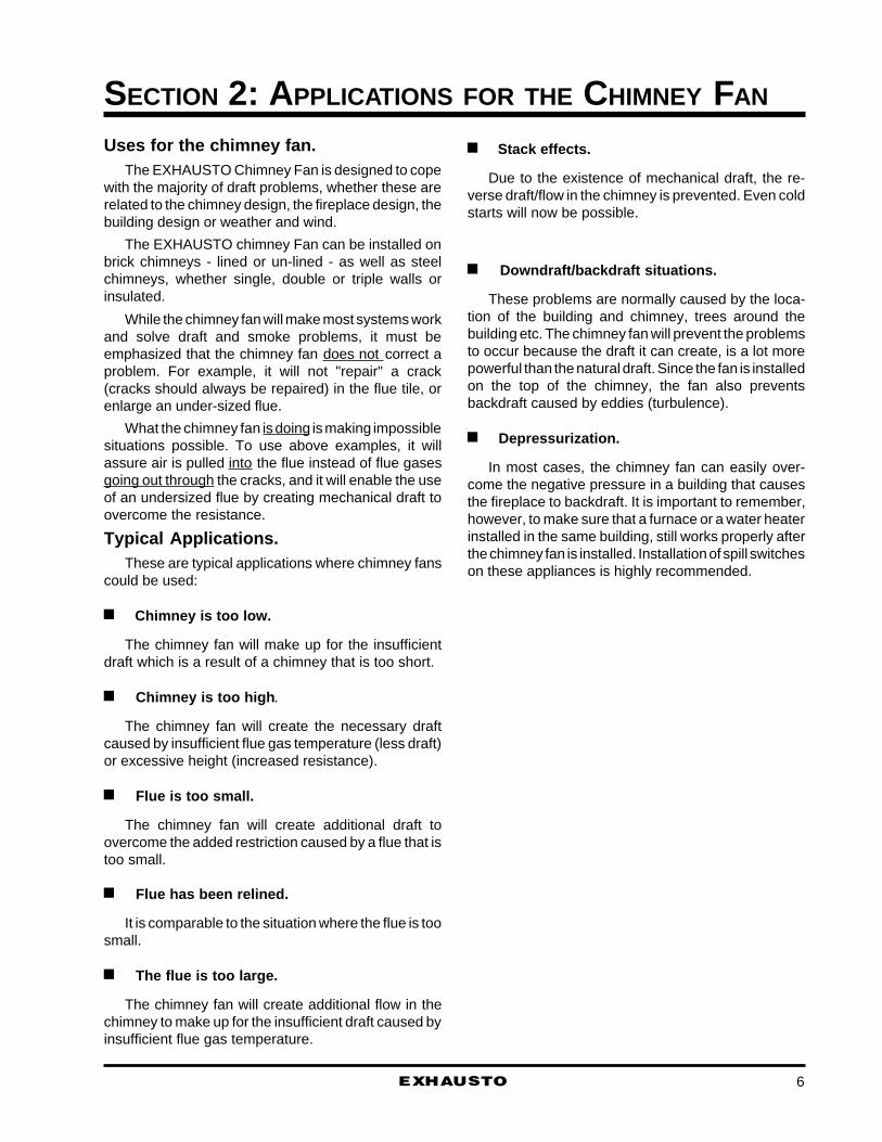
Uses for the chimney fan.The EXHAUSTO Chimney Fan is designed to cope
with the majority of draft problems, whether these arerelated to the chimney design, the fireplace design, thebuilding design or weather and wind.
The EXHAUSTO chimney Fan can be installed onbrick chimneys - lined or un-lined - as well as steelchimneys, whether single, double or triple walls orinsulated.
While the chimney fan will make most systems workand solve draft and smoke problems, it must beemphasized that the chimney fan does not correct aproblem. For example, it will not "repair" a crack(cracks should always be repaired) in the flue tile, orenlarge an under-sized flue.
What the chimney fan is doing is making impossiblesituations possible. To use above examples, it willassure air is pulled into the flue instead of flue gasesgoing out through the cracks, and it will enable the useof an undersized flue by creating mechanical draft toovercome the resistance.
Typical Applications.These are typical applications where chimney fans
could be used:
n Chimney is too low.
The chimney fan will make up for the insufficientdraft which is a result of a chimney that is too short.
n Chimney is too high .
The chimney fan will create the necessary draftcaused by insufficient flue gas temperature (less draft)or excessive height (increased resistance).
n Flue is too small.
The chimney fan will create additional draft toovercome the added restriction caused by a flue that istoo small.
n Flue has been relined.
It is comparable to the situation where the flue is toosmall.
n The flue is too large.
The chimney fan will create additional flow in thechimney to make up for the insufficient draft caused byinsufficient flue gas temperature.
EXHAUSTO 6
SECTION 2: APPLICATIONS FOR THE CHIMNEY FAN
n Stack effects.
Due to the existence of mechanical draft, the re-verse draft/flow in the chimney is prevented. Even coldstarts will now be possible.
n Downdraft/backdraft situations.
These problems are normally caused by the loca-tion of the building and chimney, trees around thebuilding etc. The chimney fan will prevent the problemsto occur because the draft it can create, is a lot morepowerful than the natural draft. Since the fan is installedon the top of the chimney, the fan also preventsbackdraft caused by eddies (turbulence).
n Depressurization.
In most cases, the chimney fan can easily over-come the negative pressure in a building that causesthe fireplace to backdraft. It is important to remember,however, to make sure that a furnace or a water heaterinstalled in the same building, still works properly afterthe chimney fan is installed. Installation of spill switcheson these appliances is highly recommended.

EXHAUSTO
SECTION 3: TECHNICAL DATA & SPECIFICATIONS
RS 12
1.2
80
37
14
11
14
4
11
Model
Discharge
Type
RPM
Voltage
Amps
Watts (output)
Weight (lbs)
A (in)
B (in)
C (in)
D (in)
E (in)
RS 16
3.9
250
61
19
16
18
4
14
RS 14
1.4
100
47
16
13
16
4
12
RS 9
0.5
25
29
12
10
11
3
8
Axial Vane
1 x 120V
Horizontal
1600
Dimensions & Electrical Data
Technical DescriptionThe EXHAUSTO chimney fan is a special designed
high temperature fan with horizontal discharge. It isETL-listed (UL Standard 378 for Draft Equipment).
The chimney fan is mounted on the top of thechimney and creates a negative pressure in the entirechimney or stack. This eliminates the risk of chimneyspillage with dangerous gases, like carbon monoxide.
Further the fan reduces the creosote build-up dra-matically and ensures an optimal combustion in fire-places, stoves, inserts, boilers, furnaces, water heat-ers, etc.
The fan is made of cast aluminum and is extremelyresistant to corrosion. The chimney fan is equippedwith axial vanes made of stainless steel, and canwithstand exhaust gases and warm air up to max.650°F (max. 300°C.). The design of the vanes assuresa minimum soot or creosote built-up on the fan base.
The top of the chimney fan is hinged to the base,which eases service and cleaning of the chimney.
The motor is a split-capacitor type constructed byEXHAUSTO to withstand high flue gas temperatures.It has thermal overload protection and is virtuallymaintenance free with pre-lubricated sealed ball bear-ing.
The motor is completely enclosed and protected
from rain, water, snow, soot, dust etc. It is balanced toassure a very low noise level and vibration-free use.
The chimney fan as an obstruction.Installed on the chimney flue termination, the chim-
ney fan could be considered a restriction to the flow.
However, the design of the fan assures a relativelylow restriction and lower than most chimney caps!
As a safety-listed product, the chimney fan hasbeen tested to a resistance factor (k-value) of 0.5,which is comparable to a 45° elbow.
Any type of chimney cap is definitely a restriction,but some more than others. Non-listed chimney capsadd the most resistance to the chimney flue. As theinlet is generally the same size as the flue, the resis-tance factor (k-value) could easily exceed that of a 90°elbow.
A UL-listed low resistance chimney cap is usuallyrated at a resistance factor of 0.5, but they are alsoaerodynamically designed to safely convey the fluegases.
The EXHAUSTO chimney fan is only a minorresistance to the chimney flue (less than most chimneycaps) provided the fan size is selected properly.
However, a fireplace that had smoke problems priorto the installation of an EXHAUSTO chimney fan, willstill have smoke problems if the fan is not operating.
Fig. 5
7
8EXHAUSTO
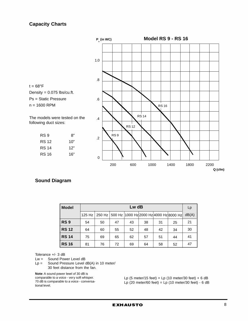
Capacity Charts
Model RS 9 - RS 16
200 600 1000 1400 1800 2200Q (cfm)
1.0
.8
.6
.4
.2
0
RS 16
RS 14
RS 12
RS 9
Ps (in WC)
t = 68°F
Density = 0.075 lbs/cu.ft.
Ps = Static Pressure
n = 1600 RPM
The models were tested on thefollowing duct sizes:
RS 9 8"
RS 12 10"
RS 14 12"
RS 16 16"
Model
RS 9
RS 12
RS 14
RS 16
125 Hz
54
64
75
81
250 Hz
50
60
69
76
500 Hz
47
55
65
72
1000 Hz
43
52
62
69
2000 Hz
38
48
57
64
4000 Hz
31
42
51
58
8000 Hz
25
34
44
52
Lp
dB(A)
21
30
41
47
Lw dB
Tolerance +/- 3 dBLw = Sound Power Level dBLp = Sound Pressure Level dB(A) in 10 meter/
30 feet distance from the fan.
Note : A sound power level of 30 dB iscomparable to a voice - very soft whisper.70 dB is comparable to a voice - conversa-tional level.
Sound Diagram
Lp (5 meter/15 feet) = Lp (10 meter/30 feet) + 6 dBLp (20 meter/60 feet) = Lp (10 meter/30 feet) - 6 dB
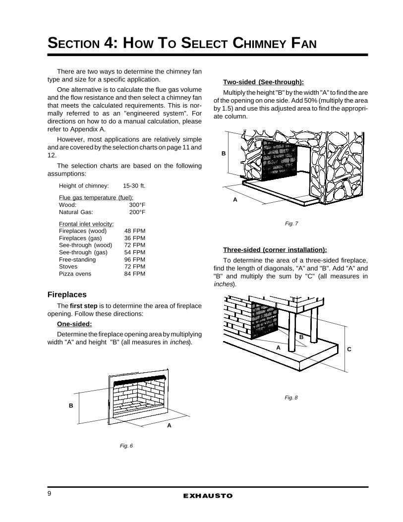
Two-sided (See-through):
Multiply the height "B" by the width "A" to find the areof the opening on one side. Add 50% (multiply the areaby 1.5) and use this adjusted area to find the appropri-ate column.
Three-sided (corner installation):
To determine the area of a three-sided fireplace,find the length of diagonals, "A" and "B". Add "A" and"B" and multiply the sum by "C" (all measures ininches).
There are two ways to determine the chimney fantype and size for a specific application.
One alternative is to calculate the flue gas volumeand the flow resistance and then select a chimney fanthat meets the calculated requirements. This is nor-mally referred to as an "engineered system". Fordirections on how to do a manual calculation, pleaserefer to Appendix A.
However, most applications are relatively simpleand are covered by the selection charts on page 11 and12.
The selection charts are based on the followingassumptions:
Height of chimney: 15-30 ft.
Flue gas temperature (fuel):Wood: 300°FNatural Gas: 200°F
Frontal inlet velocity:Fireplaces (wood) 48 FPMFireplaces (gas) 36 FPMSee-through (wood) 72 FPMSee-through (gas) 54 FPMFree-standing 96 FPMStoves 72 FPMPizza ovens 84 FPM
FireplacesThe first step is to determine the area of fireplace
opening. Follow these directions:
One-sided:
Determine the fireplace opening area by multiplyingwidth "A" and height "B" (all measures in inches).
EXHAUSTO
SECTION 4: HOW TO SELECT CHIMNEY FAN
B
A
A
B
C
A
B
Fig. 6
Fig. 7
Fig. 8
9

Free-standing (open all around)
Measure the width "A" and the depth "B" of thehood. Multiply "A" and "B" and add 50% (multiply thearea by 1.5).
If the free-standing fireplace is round, measure thediameter, D, and calculate the area by using thisformula:
Area = D x D x .7854
and add 50% (multiply the area by 1.5).
The second step is to determine the size of the flueopening. If the flue is rectangular, refer to Appendix Con how to convert a rectangular flue to a round flue.
The third step is to make sure there are no morethan two 90° bends, and the chimney height is min. 10feet and does not exceed 30 feet. If you exceed theselimits, you may need to use a stronger fan.
The fourth step is to cross reference the openingand the flue size in order to determine which size fan touse.
Stoves and fireplace insertsDetermine the are of the door opening by multiply-
ing "A" and "B". The chart on page 12 shows the size
EXHAUSTO 10
fan to use.
Wood-fired Pizza OvensDetermine the area of the door opening by multiply-
ing the measures "A" and "B"and the flue size (allmeasures in inches). Cross reference this informationfor selection of the appropriate chimney fan. The fanselection is based on max. 1/10"W.C. negative roompressure.
If the application experiences more than the al-lowed negative pressure, even if it is only temporary,select one size larger chimney fan.
Other ApplicationsIf you need a chimney fan for an application that is
not covered by the charts or if you are not sure aboutwhat’s needed for your applications, please contactEXHAUSTO at 1-800-255-2923, and we will be happyto assist you dimensioning the chimney fan.
B
A
Fig. 11
A
B
A B
Fig. 9
Fig. 10

EXHAUSTO
Fan Selection Tables for Fireplaces
Fireplace Opening (sq.in.)
Max.500
Max.800
Max.1,200
Max1,900
Max.2,500
Max.3,500
Max.5,000
Max.6,000
RS 9 RS 14 * * * * * *
RS 9 RS 12 RS 16 * * * * *
RS 9 RS 12 RS 14 RS 16 * * * *
RS9 RS 9 RS 12 RS 14 RS 16 RS 16 RS 16 *
RS 9 RS 9 RS 12 RS 14 RS 16 RS 16 RS 16 *
RS 12 RS 12 RS 12 RS 12 RS 16 RS 16 RS 16 *
RS 12 RS 12 RS 12 RS 12 RS 16 RS 16 RS 16 *
RS 12 RS 12 RS 12 RS 12 RS 16 RS 16 RS 16 *
RS 12 RS 12 RS 12 RS 12 RS 16 RS 16 RS 16 *
RS 12 RS 12 RS 12 RS 12 RS 16 RS 16 RS 16 *
6
7
8
10
12
14
16
18
20
22
Fireplaces(wood-fired)
FlueSize
6
7
8
10
12
14
16
18
20
22
Fireplaces(gas-fired)
Fireplace Opening (sq.in.)
Max.500
Max.800
Max.1,200
Max1,900
Max.2,500
Max.3,500
Max.5,000
Max.6,000
RS 9 RS 12 RS 14 * * * * *
RS 9 RS 12 RS 14 * * * * *
RS 9 RS 9 RS 12 RS 16 * * * *
RS9 RS 9 RS 12 RS 12 RS 14 RS 16 RS 16 *
RS 9 RS 9 RS 12 RS 12 RS 14 RS 16 RS 16 *
RS 12 RS 12 RS 12 RS 12 RS 14 RS 16 RS 16 *
RS 12 RS 12 RS 12 RS 12 RS 14 RS 16 RS 16 *
RS 12 RS 12 RS 12 RS 12 RS 14 RS 16 RS 16 *
RS 12 RS 12 RS 12 RS 12 RS 14 RS 16 RS 16 *
RS 12 RS 12 RS 12 RS 12 RS 14 RS 16 RS 16 *
FlueSize
NB. If your fluesize is not found inthe flue size column,always use the clos-est flue size with thelargest fan.
Example . Youropening is 750 sqin andyour flue size is 9". An8" inch flue requires amodel RS12, while a10" flue requires amodel RS 9. For a 9"flue, use a modelRS12.
11

EXHAUSTO 12
Fan Selection Tables for Stoves andFireplace Inserts
Door Opening (sq.in.)
Max. 300 Max. 300 Max. 300
RS 9 RS 9 RS 9
RS 9 RS 9 RS 9
RS 9 RS 9 RS 12
RS 9 RS 9 RS 12
RS 9 RS 9 RS 12
RS 12 RS 12 RS 14
FlueSize
FireplaceInserts
PizzaOvens *)
*) For the sizing in conjunction with a wood-fired pizza oven anegative pressure of 1/10" W.C. has been taken into consideration asmost of these ovens are used in kitchens with exhaust fans.
6
7
8
9
10
12
Stoves

Installation of the Chimney FanThe installation of the chimney fan is estimated to
take an average of 15 minutes, when installed on abrick chimney or a steel chimney. The installation timedoes not include: setting up ladder, lifting fan to the topof the chimney, cutting back flue tile etc. Only theinstallation of fiber mat, mounting brackets, steel chim-ney adaptor, safety wire, and junction box is included.
Open the carton and remove all packing materi-als.
The standard chimney fan package includes:chimney fan w. bird screen, 3-4 ft cable in conduit,weatherproof junction box (not shown), fiber mat,safety wire with anchor, Installation brackets (set of 4),motor speed control (not shown), Installation Instruc-tions and a Warranty Registration Card.
Make sure the axial vane turns without makingnoise or offering resistance. Also make sure it is inbalance.
Installation on brick chimney.
The installation procedure is the same whetherthe flue is round or rectangular.
If a clay tile flue liner is installed, it might stick upa few inches. Cut it back so it is flush with the chimneycrown.
Step1:Measure the inside of the flue and cut a matching
hole in the fiber mat. Leave a minimum distance of
EXHAUSTO
SECTION 5: INSTALLATION INSTRUCTIONS
3/4" to any side of the fiber mat.The aluminum foil on the fiber mat must face up
against the fan base.
Step 2:Locate the installation brackets in the grooves on
the underside of the fan base using the bolts and nutssupplied, to secure the brackets. Note that the boltsshall be installed from the bottom side in the two innerholes.
Adjust the final position of the installation brack-ets ensuring that there is clearance between the brack-ets and the flue wall.
If the brackets touch the flue wall, it is likely tocreate some noise from the vibration.
Step 3:The chimney fan is now ready for installation on
the top of the chimney. Place the fiber mat on the topof the chimney, with the aluminum facing upwards, andplace the fan on the top of the mat.
400°F
Fig. 12
Fig. 13
Fig. 14
Nuts
MountingBrackets
Bolts
Groove
Fiber Mat
Chimney Fan
Mounting Brackets
Fiber Mat
13
EXHAUSTO 14
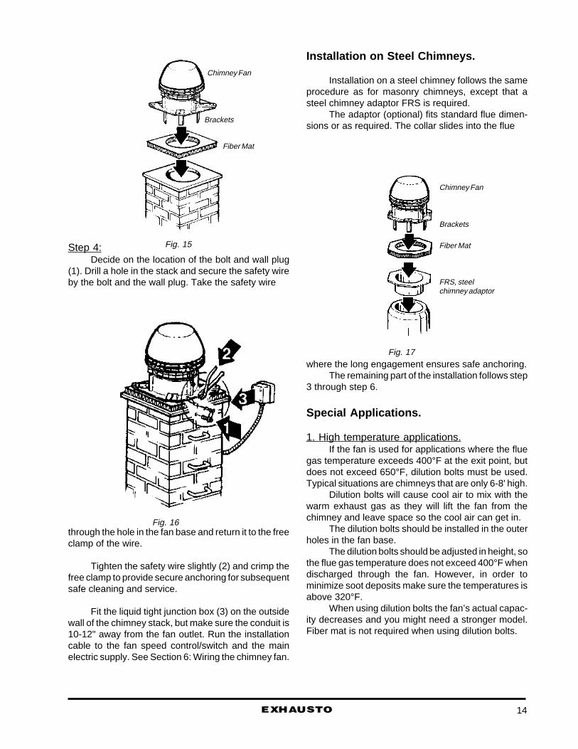
Step 4:Decide on the location of the bolt and wall plug
(1). Drill a hole in the stack and secure the safety wireby the bolt and the wall plug. Take the safety wire
through the hole in the fan base and return it to the freeclamp of the wire.
Tighten the safety wire slightly (2) and crimp thefree clamp to provide secure anchoring for subsequentsafe cleaning and service.
Fit the liquid tight junction box (3) on the outsidewall of the chimney stack, but make sure the conduit is10-12" away from the fan outlet. Run the installationcable to the fan speed control/switch and the mainelectric supply. See Section 6: Wiring the chimney fan.
Installation on Steel Chimneys.
Installation on a steel chimney follows the sameprocedure as for masonry chimneys, except that asteel chimney adaptor FRS is required.
The adaptor (optional) fits standard flue dimen-sions or as required. The collar slides into the flue
where the long engagement ensures safe anchoring.The remaining part of the installation follows step
3 through step 6.
Special Applications.
1. High temperature applications.If the fan is used for applications where the flue
gas temperature exceeds 400°F at the exit point, butdoes not exceed 650°F, dilution bolts must be used.Typical situations are chimneys that are only 6-8' high.
Dilution bolts will cause cool air to mix with thewarm exhaust gas as they will lift the fan from thechimney and leave space so the cool air can get in.
The dilution bolts should be installed in the outerholes in the fan base.
The dilution bolts should be adjusted in height, sothe flue gas temperature does not exceed 400°F whendischarged through the fan. However, in order tominimize soot deposits make sure the temperatures isabove 320°F.
When using dilution bolts the fan’s actual capac-ity decreases and you might need a stronger model.Fiber mat is not required when using dilution bolts.
Fig. 15
Fig. 17
Fig. 16
Chimney Fan
Brackets
Fiber Mat
Chimney Fan
Brackets
Fiber Mat
FRS, steelchimney adaptor
EXHAUSTO
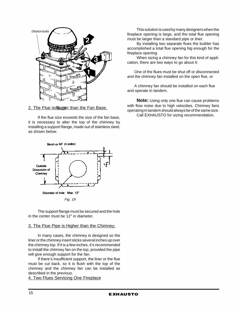
2. The Flue is Bigger than the Fan Base.
If the flue size exceeds the size of the fan base,it is necessary to alter the top of the chimney byinstalling a support flange, made out of stainless steel,as shown below.
The support flange must be secured and the holein the center must be 12" in diameter.
3. The Flue Pipe is Higher than the Chimney.
In many cases, the chimney is designed so theliner or the chimney insert sticks several inches up overthe chimney top. If it is a few inches, it’s recommendedto install the chimney fan on the top, provided the pipewill give enough support for the fan.
If there’s insufficient support, the liner or the fluemust be cut back, so it is flush with the top of thechimney and the chimney fan can be installed asdescribed in the previous.4. Two Flues Servicing One Fireplace
This solution is used by many designers when thefireplace opening is large, and the total flue openingmust be larger than a standard pipe or liner.
By installing two separate flues the builder hasaccomplished a total flue opening big enough for thefireplace opening.
When sizing a chimney fan for this kind of appli-cation, there are two ways to go about it:
One of the flues must be shut off or disconnectedand the chimney fan installed on the open flue, or
A chimney fan should be installed on each flueand operate in tandem.
Note: Using only one flue can cause problemswith flow noise due to high velocities. Chimney fansoperating in tandem should always be of the same size.
Call EXHAUSTO for sizing recommendation.
Fig. 18
Fig. 19
Dilution bolts
15
16EXHAUSTO
SECTION 6: WIRING OF THE CHIMNEY FAN
All electrical wiring must be in accordance withrequirements of the authority having jurisdiction or, inabsence of such requirements, with the National Elec-trical Code NFPA 70 - latest edition.
Power requirements for the chimney fan dependson the size in use. Electrical requirements are:
RS 9 1 x 120V/60 Cycles/0.4 AmpsRS 12 1 x 120V/60 Cycles/1.2 AmpsRS 14 1 x 120V/60 Cycles/1.4 AmpsRS 16 1 x 120V/60 Cycles/3.9 Amps
We recommend that wiring of the chimney fan isperformed by a certified electrician.
Materials needed for solid fuelapplications.
The chimney fan is equipped with about 4 feet ofhigh-temperature conduit that terminates in a pre-wired, liquid-tight junction box. Further, a motor speedcontrol is provided for installation in a regular 2x4 wallbox.
The junction box should be mounted on the sideof the chimney
The wire mostly used to power the fan, is a 2x14AWG wire with ground. If the chimney is a steelchimney (single,double or triple wall) or a solid brickchimney with a liner, the wire must be run outside thechimney in a liquid-tight conduit (if required by localcodes).
If the chimney is just a chase surrounding theactual steel chimney, the wiring can be run inside thechase, but always outside the steel chimney.
Materials needed for non-solid fuelapplications.
In addition to the materials needed for solid-fuelapplications, non-solid fuel applications (gas) shouldincorporate a fan proving switch.
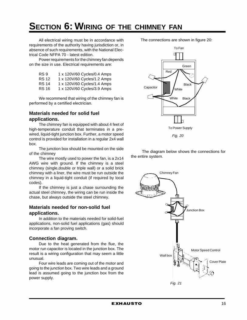
Connection diagram.Due to the heat generated from the flue, the
motor run capacitor is located in the junction box. Theresult is a wiring configuration that may seem a littleunusual.
Four wire leads are coming out of the motor andgoing to the junction box. Two wire leads and a groundlead is assumed going to the junction box from thepower supply.
Fig. 20
Fig. 21
To Power Supply
Capacitor
Red
Black
Black
Green
White
White
To Fan
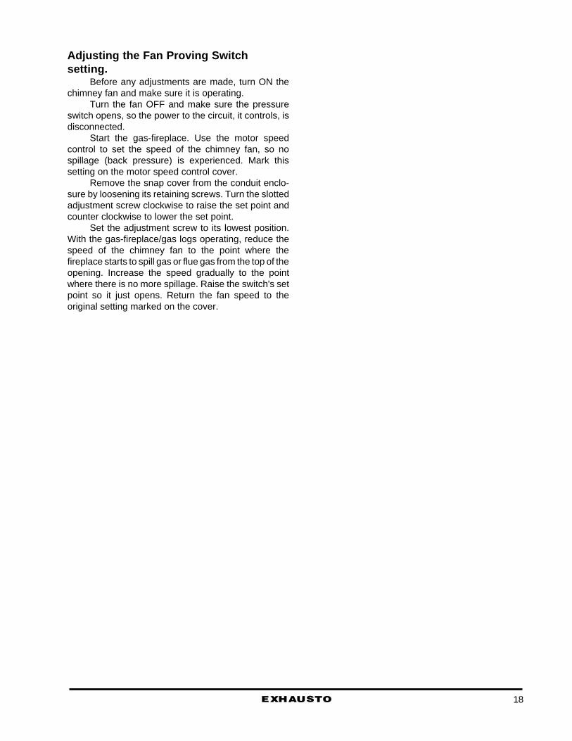
Chimney Fan
Junction Box
Wall box
Motor Speed Control
Cover Plate
The connections are shown in figure 20:
The diagram below shows the connections forthe entire system.

Fan Motor(Thermallyprotected)
Motor speedcontrol
120 volt, single phase, 60 Hz,Power Supply
M
two sheet metal screws. Run a 1/4" tube (copper oraluminum) from the switch and insert the into the sideof the chimney through the mounting bracket.
For the switch, select a location where the tem-perature is within the limits of the switch. Mount theswitch in a vertical position and follow the adjustmentdirections later in this Section.
Sequence of operation:1. The chimney fan is turned ON prior to starting
the gas-fired heating appliance.2. Operation will close the pressure switch and
activate (open) the Solenoid Gas Valve locatedbetween the gas-tank/main gas supply and theburner.
3. The fan speed, and thereby the draft, iscontrolled manually by adjustments madeto the motor speed control.
4. Any interruption of the draft causing the draft tofall below the pressure switch setting will openthe pressure switch and de-activate the Sole-noid Gas Valve.
ChimneySection
Fig. 24
Fan Proving Switch
Low Pressure Port
Fig. 23
Probe
Wiring Diagram for chimney fancontrolled by motor speed control.
This is wiring diagram for the fan.
Sequence of operation:1. The chimney fan is turned ON prior to
starting heating appliance.2. The fan speed, and thereby the draft, is
controlled manually by adjustments madeto the motor speed control.
3. When the fire in the heating appliance hasdied out, the fan can be turned OFF.
Wiring diagram for chimney fancontrolled by motor speed control andfan proving switch.
For applications using natural gas or LP gas asfuel, a fan proving switch should be used.
The wiring of the system is shown below, butattention must be paid to the installation and locationof the probe connected to the fan proving switch.
For the probe (fig. 23), drill a hole in the side ofthe chimney, attach the mounting plate over it with the
EXHAUSTO17
Adjusting the Fan Proving Switchsetting.
Before any adjustments are made, turn ON thechimney fan and make sure it is operating.
Turn the fan OFF and make sure the pressureswitch opens, so the power to the circuit, it controls, isdisconnected.
Start the gas-fireplace. Use the motor speedcontrol to set the speed of the chimney fan, so nospillage (back pressure) is experienced. Mark thissetting on the motor speed control cover.
Remove the snap cover from the conduit enclo-sure by loosening its retaining screws. Turn the slottedadjustment screw clockwise to raise the set point andcounter clockwise to lower the set point.
Set the adjustment screw to its lowest position.With the gas-fireplace/gas logs operating, reduce thespeed of the chimney fan to the point where thefireplace starts to spill gas or flue gas from the top of theopening. Increase the speed gradually to the pointwhere there is no more spillage. Raise the switch's setpoint so it just opens. Return the fan speed to theoriginal setting marked on the cover.
18EXHAUSTO
EXHAUSTO
SECTION 7: CLEANING & MAINTENANCE
How to start a fire.
FireplacesFollow instructions on how to build and maintain
a good fire.Prior to starting the fire, set the fan at full speed
and light the fire. When the flames from the kindlingload just begin to subside, add several small pieces offirewood. When the firewood has caught fire, after 5-15minutes, the speed should be reduced to a level wherea perfect flame/combustion is achieved.
When adding wood to the fire, it may be neces-sary to increase the speed for a while.
Also, if there are smoke problems they are mostlikely to incur when the fire is about to die out, so at thispoint, it may be necessary to increase the speed again.
This procedure will help conserving energy and atthe same time assure a maximum heating output fromthe fireplace.
Stoves.When starting a fire in a stove, follow the same
procedures as for a fireplace, except that the airadjustment device must be completely open duringstart up.
Cleaning IntervalsThere is no simple rule in regards to cleaning a
chimney and a chimney fan, except that when thechimney needs cleaning, so does the chimney fan.
It is recommended that the chimney, the flue pipeand the EXHAUSTO chimney fan is checked regularlyuntil a rate of creosote build-up has been determined.Clean when deposits have built up to more than 1/8".
The amount of build-up is directly related to theuse of the heating appliance and to the type of fuelbeing used. In general, gas fired systems do notrequire cleaning as often as woodfired systems.
Most modern residential systems work so effi-ciently that cleaning is only required once a year.Commercial systems (fireplaces in restaurants, hotellobbies, restaurant pizza ovens) require cleaning withshorter intervals.
Cleaning the chimney fanThe EXHAUSTO chimney fan is designed for
prolonged use. The fan should be inspected at leastonce a year when the chimney is inspected. There is noneed for lubrication as the fan is maintenance-free.
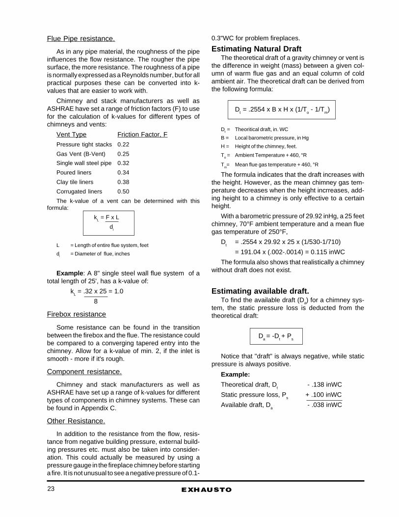
Soot, tar and other deposits should be removedfrom the fan blades and the bottom of the motorhousing.
The top of the fan is hinged and can be opened inorder to ease the cleaning.
DO NOT OPEN THE MOTOR HOUSING UN-LESS THE POWER HAS BEEN SWITCHED OFF.
Use a simple tool, like a screw driver for removingthe deposits. Make sure to fasten the security screwafter cleaning.
Fig. 20
19

Appendix
EXHAUSTO 20

EXHAUSTO
APPENDIX A: DESIGN THEORY
Fireplaces with natural draft chimneys follow thesame gravity fluid flow law as gas vents and thermalflow ventilation systems.
To a certain degree, mass flow of hot flue gasesthrough a vertical pipe is a function of the heat release,the chimney area, height, and the flow resistance(system pressure loss coefficient).
Consequently, standard sizing of chimneys mustinclude an estimate of the flue gas volume and theavailable draft. Available draft is the difference be-tween the natural draft and the system pressure loss.The available draft must be negative for the system towork.
There are limitations to this approach. A lot can bedetermined and explained via calculations, but somefactors must be determined by adding the use ofexperience and common sense. The location of abuilding, the existence of cross winds, eddies etc. areexamples of such factors. These factors can be ex-pressed as pressure losses, but it is not easy to put avalue to them.
The flue gas volume depends on the fuel burnedand the amount of air used for the combustion.
The general method to determining the flue gasvolume is to base the calculation on the air require-ments for the combustion.
The air requirement is found by determining thearea of the air inlet and multiplying this with the frontalinlet velocity.
As the air expands when it is warmed up over thefire, the actual flow in the chimney is dependent on thetemperature in the chimney.
Normally, a 300°F mean gas temperature riseabove ambient (usually 60°F) is used as a guideline,and with this temperature rise, the air will expand withalmost 60%.
The following are examples of how the flue gasvolume can be determined for different applications.
Estimating FlowThe combustion air requirement can be determined
using this formula:
Qt = q x Ainlet x Vinlet
144
Qt = Flow @ t°F (CFM, or cubic feet per minute)
Ainlet = Area of opening (square inches)
Vinlet = Frontal inlet velocity (FPM, or feet per minute)
q = Expansion factor
Flow in one-sided fireplaces used for solid fuel.
In a one-sided fireplace a frontal inlet velocity of 36-48 FPM (feet per minute) with a mean chimney tem-perature of min. 300°F should provide a good combus-tion and a well-working fireplace.
Example : Fireplace height is 24", width is 36" andthe frontal inlet velocity is estimated at 48 FPM.
The flow into the firebox is:
Q60 = 24x36 x 48 CFM = 288 CFM 144
The expansion factor is 1.6 at 300°F, so the flue gasvolume in the flue is:
Q300 = 288 CFM x 1.6 = 460 CFM
In other words, a wood-fired fireplace with a 2' x 3'opening produces 460 CFM of flue gas (flow) at anaverage flue gas temperature of 300°F.
Flow in one-sided fireplaces used for gas.
In a one-sided fireplace used for gas firing, a frontalvelocity of 18-36 FPM with a mean chimney tempera-ture of min. 200°F should provide a well-working fire-place.
The combustion air requirement can be determinedby using the formula for wood-fired fireplaces.
Example: The previous example used for gas,gives this volume into the firebox:
Q60 = 24 x 36 x 36 CFM = 216 CFM 144
The expansion factor at 200°F is 1.4, so the flue gasvolume in the flue is:
Q200 = 216 CFM x 1.4 = 302 CFM
A gas-fired fireplace produces less flue gas volumethan a wood-fired.
It is worthwhile noticing that the input of gas logs orgas burner has no major impact on the flue gas volumein an open fireplace.
Flow in open fireplaces without smokechamber.
If the fireplace does not have a smoke chamber, orif the smoke chamber is very small, it is wise to use ahigher frontal inlet velocity - preferably in the range 48-84 FPM.
21

Freestanding fireplaces
This type of fireplace requires a high frontal inletvelocity in order to capture the products of combustion.For design purposes it is recommended to use avelocity of 84-96 FPM. This is in line with the coderequirements for kitchen hoods, where a capacity of100 CFM per square foot is recommended.
Stoves and fireplace inserts
Stoves are different from open fireplaces due to thefact that they just have a small air inlet for the combus-tion air. However, the worst case scenario is when thedoors are open, so this is the situation the sizing shouldbe based on.
Again the formula:
Q300 = Ainlet x Vinlet x 1.6
144should be used, and the frontal inlet velocity recom-mended is 36-48 FPM.
The design method for a fireplace insert is similar tothe one used for a stove.
The flow is determined by using the fireplace open-ing with the doors opened as this represents a worstcase scenario.
Wood-fired Pizza Ovens
A new type of bread/pizza oven that is wood fired.
The uniqueness is the design of the oven which isboth an oven and a firebox. The door opening servesas an air inlet as well as a the flue outlet.
Even though the temperature inside the oven canreach 500°F, the flue gas temperature is much lowerdue to the design of the smoke chamber. The smokechamber is just a small hood that leads into the flue.
For design purposes, it is recommended that afrontal inlet velocity of 84-96 FPM is used.
The formula for calculating the flue gas volume is:
Q300 = A x B x Vinlet x 1.6
144
A = Height of door opening
B = Width of door opening
Estimating Flow ResistanceThe total flow resistance in a vent system that
moves air, is normally referred to as "total staticpressure loss". The formula used to determine thestatic pressure loss in a system is:
EXHAUSTO 22
Ps = .015 x dm x Vpipe2 x Σk
or
Ps = .015 x dm x (Qt / Apipe)2 x Σk
dm = gas density, lb/ft3
Vpipe = system gas velocity (flue gas volume/flue area) at mean condition, Ft/s
Apipe = area of flue, square inches
Σ k = Sum of all resistance factors
There are several factors creating resistance in afireplace/chimney systems:
The flue.
Flue components
The transition from firebox to flue.
In addition there are "external" factors influencingthe resistance:
Internal building pressure.
External building pressure.
Wind pattern.
When trying to determining the total resistance in achimney system, it eases the work to use resistancefactors, or k-values. Any part of a chimney system orduct can be assigned a k-value, and the higher thevalue, the more resistance.
K-values are dimensionless and are used in mostother industries dealing with air-flow and vents, likef.inst. the ventilation industry.
There are only a few differences between a ventila-tion system and a chimney system:
1. A chimney system has natural draft to removethe flue gases, as long as there is a verticalchimney or vent. A ventilation system does nothave any natural draft, so mechanical draftfans are always required.
2. A chimney system deals with high temperature airwith products of combustion. A venti lation sys-tem removes room temperature air with dust par-ticles.
3. Chimney flues are build of stainless steel pipe,sheet metal, steel liner, tile liner, or poured/cast-in-place liners. Most ventilation systems use prefab-ricated vents of sheet metal or plastic.
In other words: A chimney system removes air witha higher temperature and a lower density than aventilation system. Further the ventilation system isoften built in a material with less flow resistance.
Flue Pipe resistance.
As in any pipe material, the roughness of the pipeinfluences the flow resistance. The rougher the pipesurface, the more resistance. The roughness of a pipeis normally expressed as a Reynolds number, but for allpractical purposes these can be converted into k-values that are easier to work with.
Chimney and stack manufacturers as well asASHRAE have set a range of friction factors (F) to usefor the calculation of k-values for different types ofchimneys and vents:
Vent Type Friction Factor, F
Pressure tight stacks 0.22
Gas Vent (B-Vent) 0.25
Single wall steel pipe 0.32
Poured liners 0.34
Clay tile liners 0.38
Corrugated liners 0.50
The k-value of a vent can be determined with thisformula:
kL = F x L
di
L = Length of entire flue system, feet
di = Diameter of flue, inches
Example : A 8" single steel wall flue system of atotal length of 25', has a k-value of:
kL = .32 x 25 = 1.0
8
Firebox resistance
Some resistance can be found in the transitionbetween the firebox and the flue. The resistance couldbe compared to a converging tapered entry into thechimney. Allow for a k-value of min. 2, if the inlet issmooth - more if it's rough.
Component resistance.
Chimney and stack manufacturers as well asASHRAE have set up a range of k-values for differenttypes of components in chimney systems. These canbe found in Appendix C.
Other Resistance.
In addition to the resistance from the flow, resis-tance from negative building pressure, external build-ing pressures etc. must also be taken into consider-ation. This could actually be measured by using apressure gauge in the fireplace chimney before startinga fire. It is not unusual to see a negative pressure of 0.1-
0.3"WC for problem fireplaces.
Estimating Natural DraftThe theoretical draft of a gravity chimney or vent is
the difference in weight (mass) between a given col-umn of warm flue gas and an equal column of coldambient air. The theoretical draft can be derived fromthe following formula:
Dt = .2554 x B x H x (1/T
o - 1/T
m)
Dt = Theoritical draft, in. WC
B = Local barometric pressure, in Hg
H = Height of the chimney, feet.
To = Ambient Temperature + 460, °R
Tm= Mean flue gas temperature + 460, °R
The formula indicates that the draft increases withthe height. However, as the mean chimney gas tem-perature decreases when the height incrreases, add-ing height to a chimney is only effective to a certainheight.
With a barometric pressure of 29.92 inHg, a 25 feetchimney, 70°F ambient temperature and a mean fluegas temperature of 250°F,
Dt
= .2554 x 29.92 x 25 x (1/530-1/710)
= 191.04 x (.002-.0014) = 0.115 inWC
The formula also shows that realistically a chimneywithout draft does not exist.
Estimating available draft.To find the available draft (Da) for a chimney sys-
tem, the static pressure loss is deducted from thetheoretical draft:
Da = -D
t + P
s
Notice that "draft" is always negative, while staticpressure is always positive.
Example:
Theoretical draft, Dt
- .138 inWC
Static pressure loss, Ps
+ .100 inWC
Available draft, Da
- .038 inWC
EXHAUSTO23

Analysing a fireplace venting system.This is an example on how to analyze and estimate
fireplace system:
One-sided fireplace, opening = 24"x36"
Ambient temperature = 60°F
Mean chimney temperature = 300°F
Flue material = Single wall steel pipe
Flue size = 8"
Chimney height from top of firebox = 25'
Off sets = One 30° off-set (= 2 x 30° elbows)
dm
= 0.075 lb/ft3 @ 60°F
= 0.047 lb/ft3 @ 300°F
1. Determine flow:
Qt
= q x Ainlet
x Vinlet
/ 144
= 1.6 x 24 x 36 x 48 CFM
= 460 CFM
2. Determine k-values:
Pipe:
kL
= F x L /Di
= .32 x 25/8
= 1.0
Components:
2 x 30° elbows = 2 x .15 .30
Inlet from firebox 2.00
Total k-value 2.30
Σ Σ Σ Σ Σ k = 1.0 + 2.3 = 3.3
3. Determine flow resistance:
Ps = .015 x dm x (Qt /Apipe)² x Σk
= .015 x .047 x (460/50)² x 3.3
= .015 x .047 x 84.64 x 3.3
= .197"WC
4. Determine natural draft:
Dt = .2554 x B x H x (1/To - 1/Tm)
= .2554 x 29.92 x (1/530 - 1/710)
= 191.04 x (.002 - .0014) = .115"WC
5. Determine available draft:
-Da = -Dt + Ps
= - .115 + 0.197
= + .082"WC
The available draft is positive. In other words, thesystem should be back-drafting. One way of solving thisproblem could be to increase the flue size from 8" to 10".Going through the same calculations, a 10" flue wouldgive these results:
Qt = 460 CFM (no change)
kL = .8
Σ k = 3.1
Ps
= .015 x .047 x (460/78.5)² x 3.1
= .015 x .047 x 34.34 x 3.1
= .075"WC
Dt = .115"WC (no change)
Da
= -.115 + .075
= -.04"WC
Now there is draft in the system, so a 10" vent is theappropriate size for venting a 24"x36" fireplace.
Analyzing other factorsIf the fireplace and the flue seem to be sized
correctly, but there is a smoke problem other informa-tion may be needed.
F.inst. a depressurized building will negatively affectthe draft situation. If the negative pressure is found tobe, let's say .1"WC the available draft in above examplewould be:
Da
= -.04"WC + .1"WC
= +.06"WC
In other words, the negative building pressure easilyovercomes the draft and makes the system back-draft.
24EXHAUSTO
APPENDIX B: CONVERSION OF RECTANGULAR FLUES
EXHAUSTO
4 5 6 7 8 9 10 11 12 13 14 15 16 17 18 19 20
4 4 4 5 5 5 6 6 6 6 6 6 6 6 6 7 7 7
5 4 5 5 6 6 6 7 7 7 7 7 8 8 8 8 8 8
6 5 5 6 6 7 7 8 8 8 8 8 9 9 9 9 9 9
7 5 6 6 7 7 8 8 9 9 9 9 10 10 10 10 10 10
8 5 6 7 7 8 8 9 9 10 10 10 10 11 11 11 11 11
9 6 6 7 8 8 9 9 10 10 11 11 11 12 12 12 12 12
10 6 7 8 8 9 9 10 10 11 11 12 12 12 13 13 13 13
11 6 7 8 9 9 10 10 11 11 12 12 13 13 13 14 14 14
12 6 7 8 9 10 10 11 11 12 12 13 13 14 14 14 15 15
13 6 7 8 9 10 11 11 12 12 13 13 14 14 15 15 15 16
14 6 7 8 9 10 11 12 12 13 13 14 14 15 15 16 16 16
15 6 8 8 9 10 11 12 13 13 14 14 15 15 16 16 17 17
16 6 8 9 10 11 12 12 13 14 14 15 15 16 16 17 17 18
17 6 8 9 10 11 12 13 13 14 15 15 16 16 17 17 18 18
18 7 8 9 10 11 12 13 14 14 15 16 16 17 17 18 18 19
19 7 8 9 10 11 12 13 14 15 15 16 17 17 18 18 19 19
20 7 8 9 10 11 12 13 14 15 16 16 17 18 18 19 19 20
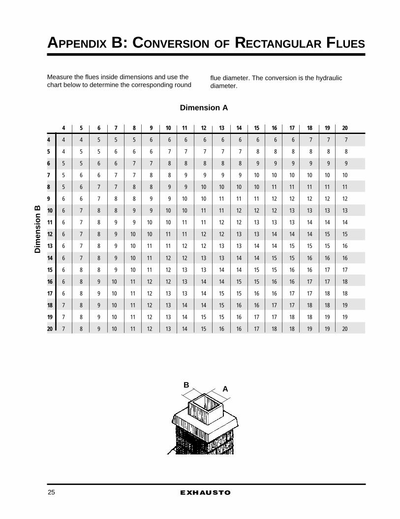
Dimension A
Dim
ensi
on B
Measure the flues inside dimensions and use thechart below to determine the corresponding round
flue diameter. The conversion is the hydraulicdiameter.
AB
25
EXHAUSTO
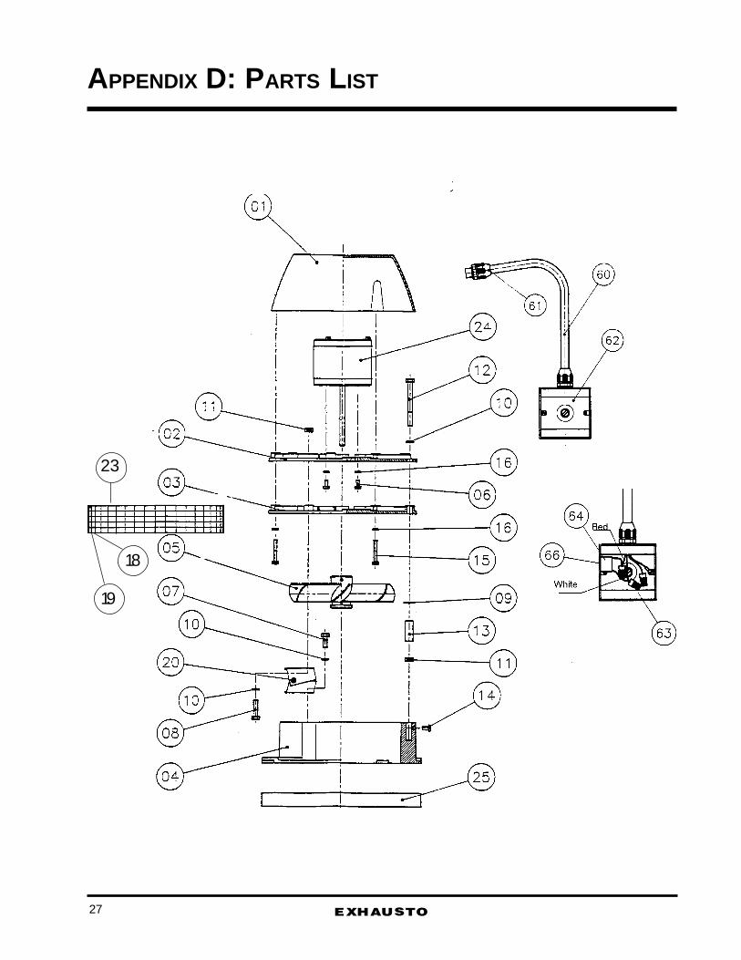
APPENDIX D: PARTS LIST
23
18
19
27

EXHAUSTO 28
Position Description Number needed
01 Motor Cover 102 Motor mounting plate 103 Motor cooling plate 104 Fan base 105 Axial vane (stainless) 106 Screw - M6 x 16 (stainless) 407 Bolt - M8 x 20 208 Bolt - M8 x 30 209 Washer - 8 mm 110 Washer - 8 mm 511 Nut - M8 312 Bolt - M8 x 80 (stainless) 113 Distance tube 114 Bolt - M6 x 12 (stainless) 115 Bolt - M6 x 45 (stainless) 316 Washer - 6 mm 718 Clip for spark arrester 319 Rivet 320 Hinges - set (left/right) 121 Mounting brackets (set) 123 Spark arrester 124 Motor 125 Fiber mat 160 3/8" hi-temp conduit 161 1/2" connector 262 2x4" junction box (liquid) 163 Wire nuts 464 Motor run capacitor 1
EXHAUSTO
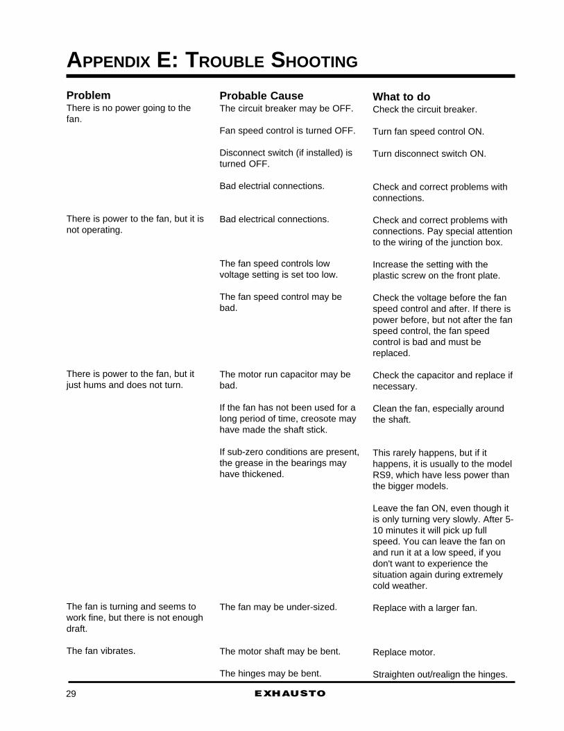
APPENDIX E: TROUBLE SHOOTING
ProblemThere is no power going to thefan.
There is power to the fan, but it isnot operating.
There is power to the fan, but itjust hums and does not turn.
The fan is turning and seems towork fine, but there is not enoughdraft.
The fan vibrates.
What to doCheck the circuit breaker.
Turn fan speed control ON.
Turn disconnect switch ON.
Check and correct problems withconnections.
Check and correct problems withconnections. Pay special attentionto the wiring of the junction box.
Increase the setting with theplastic screw on the front plate.
Check the voltage before the fanspeed control and after. If there ispower before, but not after the fanspeed control, the fan speedcontrol is bad and must bereplaced.
Check the capacitor and replace ifnecessary.
Clean the fan, especially aroundthe shaft.
This rarely happens, but if ithappens, it is usually to the modelRS9, which have less power thanthe bigger models.
Leave the fan ON, even though itis only turning very slowly. After 5-10 minutes it will pick up fullspeed. You can leave the fan onand run it at a low speed, if youdon't want to experience thesituation again during extremelycold weather.
Replace with a larger fan.
Replace motor.
Straighten out/realign the hinges.
Probable CauseThe circuit breaker may be OFF.
Fan speed control is turned OFF.
Disconnect switch (if installed) isturned OFF.
Bad electrial connections.
Bad electrical connections.
The fan speed controls lowvoltage setting is set too low.
The fan speed control may bebad.
The motor run capacitor may bebad.
If the fan has not been used for along period of time, creosote mayhave made the shaft stick.
If sub-zero conditions are present,the grease in the bearings mayhave thickened.
The fan may be under-sized.
The motor shaft may be bent.
The hinges may be bent.
29
EXHAUSTO 30
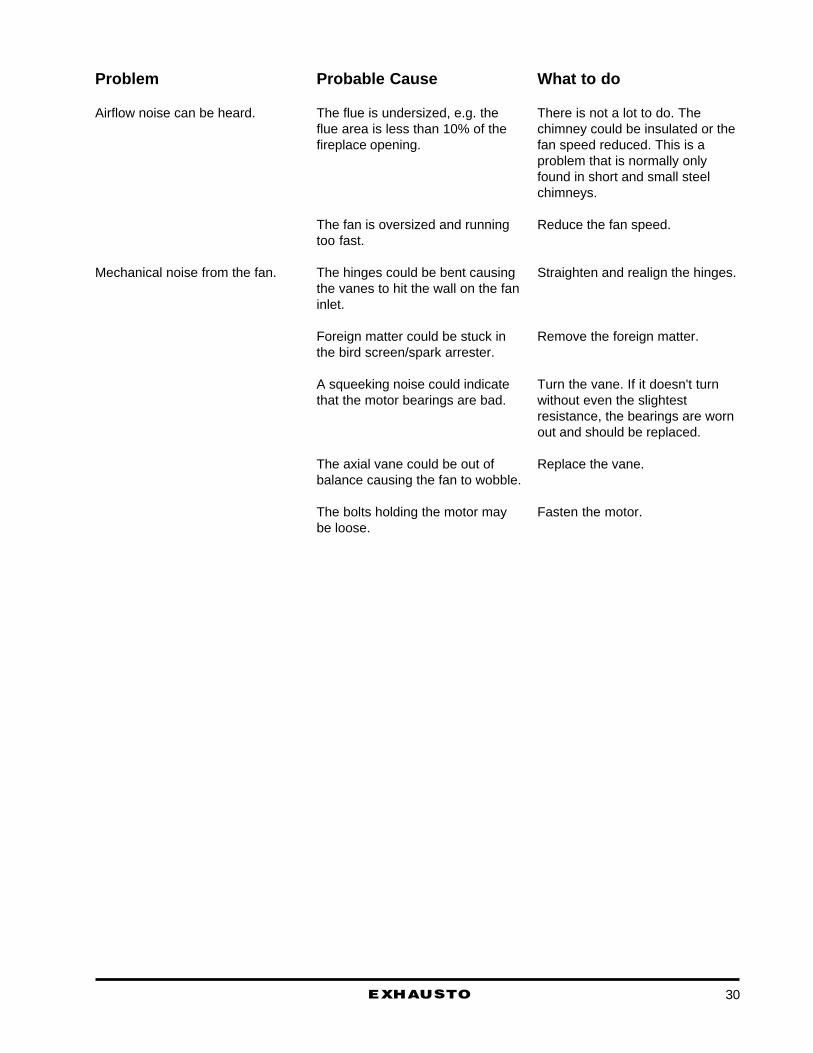
What to do
There is not a lot to do. Thechimney could be insulated or thefan speed reduced. This is aproblem that is normally onlyfound in short and small steelchimneys.
Reduce the fan speed.
Straighten and realign the hinges.
Remove the foreign matter.
Turn the vane. If it doesn't turnwithout even the slightestresistance, the bearings are wornout and should be replaced.
Replace the vane.
Fasten the motor.
Probable Cause
The flue is undersized, e.g. theflue area is less than 10% of thefireplace opening.
The fan is oversized and runningtoo fast.
The hinges could be bent causingthe vanes to hit the wall on the faninlet.
Foreign matter could be stuck inthe bird screen/spark arrester.
A squeeking noise could indicatethat the motor bearings are bad.
The axial vane could be out ofbalance causing the fan to wobble.
The bolts holding the motor maybe loose.
Problem
Airflow noise can be heard.
Mechanical noise from the fan.

EXHAUSTO
APPENDIX F: WARRANTIES
WarrantiesThe EXHAUSTO chimney fans have a 2 year
Factory Warranty, a 10 year Corrosion PerforationWarranty and a 6 month Satisfaction Guarantee.
IN ORDER TO BE ELIGIBLE FOR WARRANTYAND GUARANTEE COVERAGE IT IS A PROVISIONTHAT A WARRANTY REGISTRATION FORM HASBEEN SUBMITTED TO EXHAUSTO WITHIN 30 DAYSFROM THE DATE OF INSTALLATION.
EXHAUSTO RESERVE THE RIGHT TO REFUSEANY WARRANTY CLAIM IF THE WARRANTY REG-ISTRATION FORM HAS NOT BEEN MAILED IN.
2-Year Factory Warranty.We promise the original user that we will replace or
repair as we may elect, any part of parts of the newEXHAUSTO chimney fan which are defective in mate-rial or workmanship without charge for parts or labor(not including labor for dismantling and installation,freight etc.) during the first 2 years following the date ofinstallation.
10-Year Corrosion Perforation Warranty.We promise the original user that we will replace or
repair as we may elect, any part or parts of theEXHAUSTO chimney fan which are perforated due tocorrosion without charge for parts or labor (not includ-ing dismantling and installation, freight etc.) during thefirst 10 years following the date of installation.
General Warranty Provisions.What the user must do: We recommend that you
contact the dealer where you purchased the chimneyfan, however, you may also contact EXHAUSTO di-rectly.
What is not covered: Any non-EXHAUSTO productwhich may be installed in or upon or related to theproduct is excluded.
Limitations on our responsibility: Please carefullynote that this is a two-way agreement. We promise tomake free replacements as stated, but you agree that,except for our obligation to make good on this promise,we shall not be responsible for any expenses orinconvenience which you might incur or experiencewith respect to our product, nor shall we be liable fordefects, damage or failures, caused by unauthorizedalterations, unreasonable use, accident or abuse, in-cluding failure to provide reasonable and necessarymaintenance, after our product has been delivered toyou. Some states do not allow the exclusion or limita-tion of incidental or consequential damages, so theabove limitations or exclusions may not apply to you.
This warranty gives you specific legal rights, and youmay also have other rights which vary from state tostate.
THESE WARRANTIES ARE IN LIEU OF ALLOTHER WARRANTIES, EXPRESSED OR IMPLIED.WARRANTIES OF MERCHANTABILITY AND FIT-NESS FOR PARTICULAR PURPOSES ARE EX-CLUDED, AS ARE ALL OTHER REPRESENTATIONSTO THE ORIGINAL PURCHASER, AND ALL OTHEROBLIGATIONS OR LIABILITIES, INCLUDING LIABIL-ITY FOR INCIDENTAL AND CONSEQUENTIAL DAM-AGES, ON THE PART OF EXHAUSTO OR THESELLER.
6 Months Performance Guarantee.This guarantee allows a customer to return an
EXHAUSTO chimney fan for a full refund (not toinclude freight, installation or dismantling charges), ifthe customer should decide that, within six (6) monthsfrom the date of installation, the fan does not give fullsatisfaction.
Warranty Claim Procedures.When the dealer files for warranty coverage on
behalf of your customer you must follow these warrantyclaim procedures:
a. If filing a warranty claim under the Two (2) YearFactory Warranty or under the Ten (10) Year CorrosionPerforation Warranty, follow this procedure:
1. Call EXHAUSTO at 1-800-255-2923 and explainwhat your warranty problem is. Be sure to have modeltype, place and date of purchase available. If thisinformation is not available, EXHAUSTO might not beable to accept your warranty claim.
2. If the problem can not be solved over the phone,you will be given an authorization to ship the chimneyfan back to EXHAUSTO, freight prepaid.
3. If the chimney fan is returned for repair, thechimney fan will be returned to the customer as soonas the warranty claim has been satisfied.
If the repair of the chimney fan involved repair ofother parts than the warranty claim called for, EX-HAUSTO reserves the right to charge the customer forsuch repair.
B. If filing a claim under Six (6) Months PerformanceGuarantee, follow this procedure:
1. Call EXHAUSTO at 1-800-255-2923 and explainwhat the problem is.
2A. If the problem is, that the application calls for abigger chimney fan than originally specified and cus-
31

EXHAUSTO 32
tomers wants a fan with a higher capacity, EXHAUSTOwill replace the first chimney fan with the bigger fan forthe difference in price.
2B. If the customer wants to return the chimney fanand receive a refund, the customer must furnish proofof payment including. place and date of purchase.
EXHAUSTO will inspect the returned unit uponreceipt and the dealer will receive the refund within 30days from receipt of the chimney fan. If any damagesare detected on the chimney fan, EXHAUSTO re-serves the right to charge for the repair and deduct thatin the refund.

EXHAUSTO33
Notes

EXHAUSTO 34
Notes

EXHAUSTO35
Notes