Embed Size (px)
Citation preview
© Festo Didactic 88765-00 135
When you have completed this exercise, you will be familiar with the hydraulic schematic and components of the nacelle trainer. You will identify components, measure pressure, and change the state of some valves via the HMI. Finally, you will use your hands to change the hydraulic oil and filter.
The Discussion of this exercise covers the following points:
Complete hydraulic circuit
Components of the hydraulic circuitManifold block. Pump and motor. Hand pump. Accumulator. Valves. Pressure gauges. Pressure transducers and pressure switch.
Sections of the hydraulic circuitPower unit. Accumulation. Oil filtration. Backup power. Rotor brake and yaw brake.
DEBUG mode
Complete hydraulic circuit
Have a look at the complete hydraulic circuit for the nacelle trainer in Figure 3-22 below. It is broken down into sections to facilitate understanding.
a A full-size version of the hydraulic circuit can be found in Appendix D.
Basic Hydraulic Circuit
Exercise 3-1
EXERCISE OBJECTIVE
DISCUSSION OUTLINE
DISCUSSION

Ex. 3-1 – Basic Hydraulic Circuit Discussion
136 © Festo Didactic 88765-00
Figure 3-22. Entire nacelle hydraulic circuit.
a The brakes are covered in Ex. 3-2.
Components of the hydraulic circuit
Manifold block
Most of the hydraulic components are attached to the aluminum block depicted in Figure 3-23. The use of manifold and cartridge valves reduces the number of joints where leaks could develop and saves space, making the system more easily serviceable.
Power unit
Accumulation
Oil filtration
Backup power
Rotor brake
Yaw brake
Manifold

Ex. 3-1 – Basic Hydraulic Circuit Discussion
© Festo Didactic 88765-00 137
Figure 3-23. Manifold block.
Pump and motor
An external gear pump supplies hydraulic power to the nacelle trainer. Such gear pumps are commonly used for high-pressure applications. They are compact, relatively inexpensive, and have few moving parts. They typically consist of two gears that mesh with each other inside a housing, as shown in Figure 3-24.
Figure 3-24. Inside a gear pump.
The driving gear is coupled to a motor. Figure 3-25 shows that when the driving gear rotates, it drives a second gear. With both gears rotating, fluid is drawn into the pump because of the vacuum created by the separation of the gears on the inlet side. This fluid is trapped between the housing and the rotating teeth of the gears, where it travels around the housing. It is then pushed out of the pump as the volume diminishes between the interlocking gears on the outlet side.
Figure 3-25. Model of a gear pump.
The theoretical displace-
ment of the pump is
0.7 mL/rev
(0.00018 gal U.S./rev).
Since the motor can rotate
at 3450 RPM, the maximum
pumped volume is 2.4 L/min
(0.6 gal U.S./min).
Inlet Outlet
Driving gear
Driven gear
Inlet
Outlet
Ex. 3-1 – Basic Hydraulic Circuit Discussion
138 © Festo Didactic 88765-00
An external gear pump is a positive displacement rotary pump. This means that it pumps a given amount of fluid per revolution. Gear pumps, like all positive displacement pumps, can be damaged when operating against a closed discharge. Therefore, they require a pressure relief valve.
Hand pump
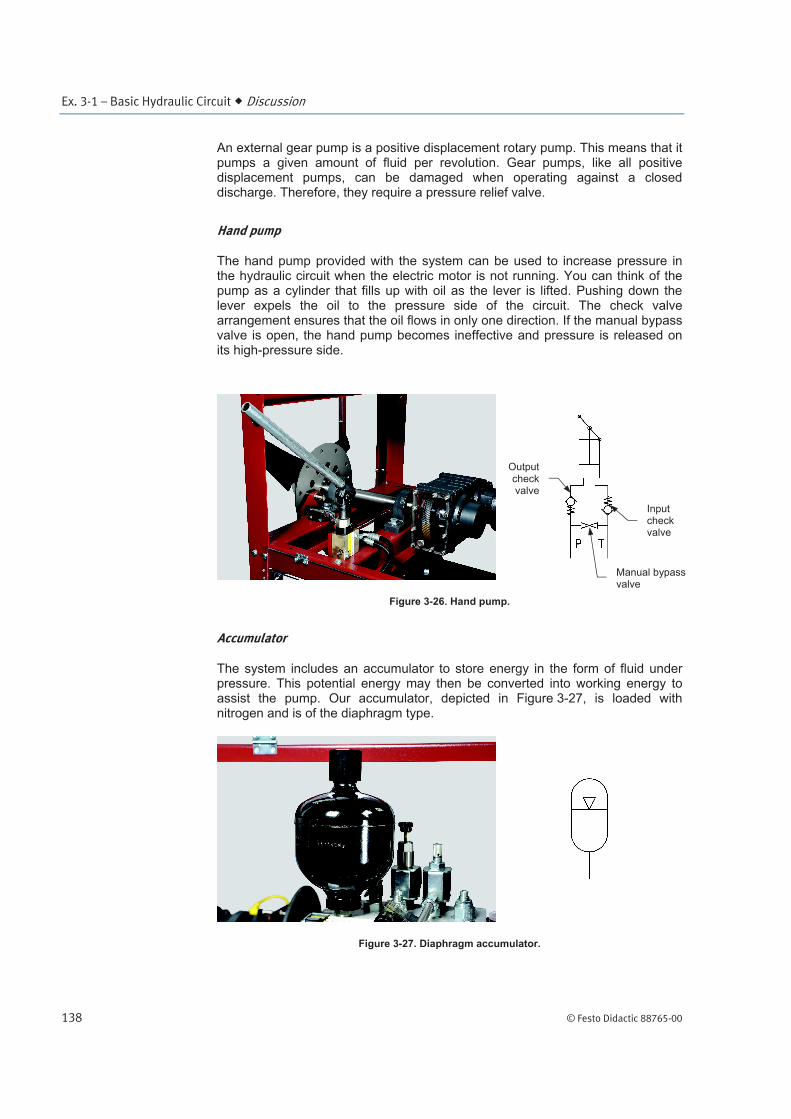
The hand pump provided with the system can be used to increase pressure in the hydraulic circuit when the electric motor is not running. You can think of the pump as a cylinder that fills up with oil as the lever is lifted. Pushing down the lever expels the oil to the pressure side of the circuit. The check valve arrangement ensures that the oil flows in only one direction. If the manual bypass valve is open, the hand pump becomes ineffective and pressure is released on its high-pressure side.
Figure 3-26. Hand pump.
Accumulator
The system includes an accumulator to store energy in the form of fluid under pressure. This potential energy may then be converted into working energy to assist the pump. Our accumulator, depicted in Figure 3-27, is loaded with nitrogen and is of the diaphragm type.
Figure 3-27. Diaphragm accumulator.
Manual bypass valve
Outputcheckvalve
Input check valve

Ex. 3-1 – Basic Hydraulic Circuit Discussion
© Festo Didactic 88765-00 139
Valves
Valves regulate fluid flow and pressure in the system. In addition to the hydraulic schematic, Appendix C lists the different valves that are included in the system. Figure 3-28 to Figure 3-33 show all valves and their corresponding symbols.
Figure 3-28. Check valves CV1 and CV2.
Figure 3-29. Relief valves RV1 and RV2.
Figure 3-30. Directional valve MV1.

Ex. 3-1 – Basic Hydraulic Circuit Discussion
140 © Festo Didactic 88765-00
Figure 3-31. Directional valve SV1.
Figure 3-32. Directional valves SV2 and SV6.
Figure 3-33. Directional valves SV3, SV4, and SV5.
All of them are of the cartridge type. Valve MV1 is manually actuated (Figure 3-34).

Ex. 3-1 – Basic Hydraulic Circuit Discussion
© Festo Didactic 88765-00 141
Figure 3-34. MV1 deactuated (left) and actuated (right).
Valves SV1 through SV6 are actuated with a solenoid and pilot (Figure 3-35) or using a manual override. Three types of overrides exist on the system. Figure 3-36 shows their deactuated state in which they should normally be left while Figure 3-37 shows the actuated state for each of the three types.
Figure 3-35. Pilot light showing that the valve is actuated via the solenoid.
Pilot light

Ex. 3-1 – Basic Hydraulic Circuit Discussion
142 © Festo Didactic 88765-00
Figure 3-36. Three different types of manual overrides deactuated.

Ex. 3-1 – Basic Hydraulic Circuit Discussion
© Festo Didactic 88765-00 143
Figure 3-37. Three different types of manual overrides actuated.
Pressure gauges
The two gauges shown in Figure 3-38 are used with quick disconnect hoses to measure pressure on the fittings located on the manifold.
Figure 3-38. Pressure gauges.

Ex. 3-1 – Basic Hydraulic Circuit Discussion
144 © Festo Didactic 88765-00
Pressure transducers and pressure switch
The nacelle trainer has two pressure transducers: PSP2 (accumulator) and PSB2 (rotor brake). They convert pressure into 4-20 mA signals. These transducers are connected to analog input cards on the distributed I/O rack.
Figure 3-39. Pressure transducer.
The trainer also features a pressure switch, PSB1, which sends 24 V when pressure is high at the yaw brake and 0 V when pressure is low (Figure 3-40).
Figure 3-40. Pressure switch.
Sections of the hydraulic circuit
Power unit
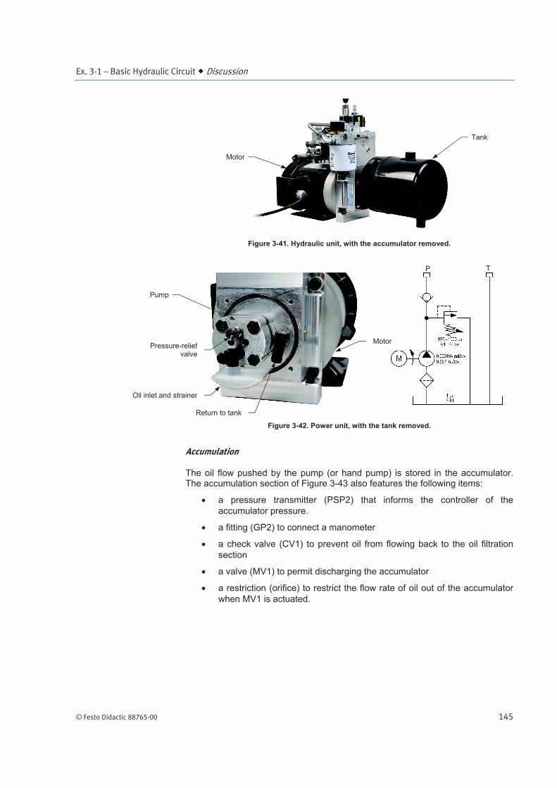
What is coined by the term “power unit” consists of the motor, pump, and tank assembly. A strainer is located between the tank and the pump to prevent debris from entering the circuit. A check valve at the pressure (P) output prevents oil from coming back to the power unit. To limit the pressure in the system, a pressure relief valve returns the oil to the tank when pressure exceeds between 63 bar and 69 bar (925 psi and 1000 psi) at the pump output.
Ex. 3-1 – Basic Hydraulic Circuit Discussion
© Festo Didactic 88765-00 145
Figure 3-41. Hydraulic unit, with the accumulator removed.
Figure 3-42. Power unit, with the tank removed.
Accumulation
The oil flow pushed by the pump (or hand pump) is stored in the accumulator. The accumulation section of Figure 3-43 also features the following items:
a pressure transmitter (PSP2) that informs the controller of the
accumulator pressure.
a fitting (GP2) to connect a manometer
a check valve (CV1) to prevent oil from flowing back to the oil filtration
section
a valve (MV1) to permit discharging the accumulator
a restriction (orifice) to restrict the flow rate of oil out of the accumulator
when MV1 is actuated.
P T
Pressure-reliefvalve
Oil inlet and strainer
Return to tank
Motor
Tank
Motor
Pump

Ex. 3-1 – Basic Hydraulic Circuit Discussion
146 © Festo Didactic 88765-00
Figure 3-43. Accumulation circuit.
Oil filtration
Oil is filtered for about ten seconds every time the hydraulic pump is actuated. When valve SV1 is actuated, oil circulates through the filtration circuit (Figure 3-44).
Figure 3-44. Oil path during filtration.
The filter needs to be changed when the filter clogging indicator is in the red zone during filtration (Figure 3-45). The oil may also need to be changed after a certain number of hours of operation or if analysis shows that the base oil is degraded or the additives are depleted.
a Replace the filter as well if you ever need to change the oil.
Back to the tank
From pressure
port
P
Valve SV1 is shown actuated

Ex. 3-1 – Basic Hydraulic Circuit Discussion
© Festo Didactic 88765-00 147
Figure 3-45. Clogging indicator.
A filter wrench (Figure 3-46) is provided with the training system. It should only be used to remove the oil filter. The new spin-on filter can be screwed in by hand.
Figure 3-46. Filter wrench.
Backup power
Figure 3-47 shows that a hand pump is installed to provide hydraulic pressure when the hydraulic pump is off. Relief valve RV2 prevents the hand pump from increasing hydraulic pressure beyond 69 bars (1000 psi). Finally, check valve CV2 prevents system pressure from flowing back to the hand pump.
Figure 3-47. Oil path through hand pump.
From tank
To accumulator

Ex. 3-1 – Basic Hydraulic Circuit Discussion
148 © Festo Didactic 88765-00
Rotor brake and yaw brake
The two brake sections are covered in Ex. 3-2. Nonetheless, in order for you to get a good understanding of the hydraulic circuit, Figure 3-48 depicts the two schematics.
Figure 3-48. Rotor brake and yaw brake circuits.
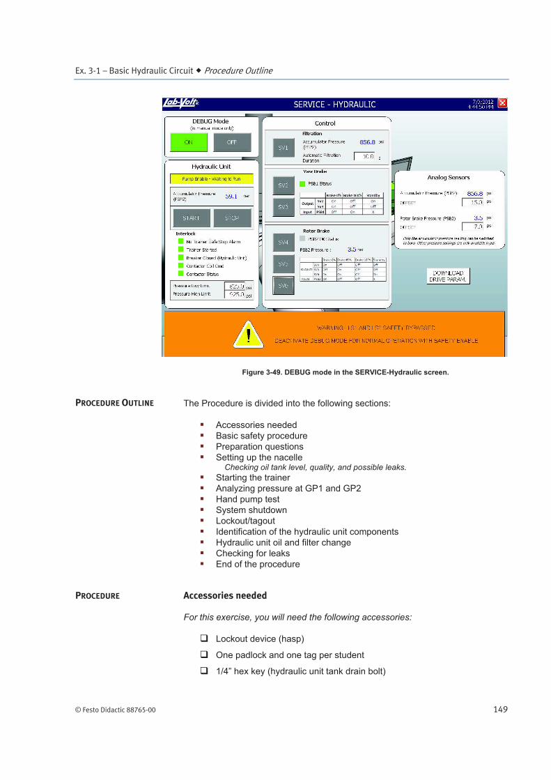
DEBUG mode
Up until now, you could not simultaneously open the safety panels and do anything significant on the HMI because an alarm would instantly be triggered. However, you sometimes need to leave the hydraulic unit power on to troubleshoot the hydraulic circuit.
This is when the DEBUG mode of the SERVICE – Hydraulic screen comes into play (Figure 3-49). This mode disables the alarm caused by opening the safety panels and permits to open or close the valves SV1 to SV6 manually or from the HMI.
a The DEBUG mode remains safe because you are locked into this screen and you cannot start the drive train until you turn it off.
T
T
P
P
Ex. 3-1 – Basic Hydraulic Circuit Procedure Outline
© Festo Didactic 88765-00 149
Figure 3-49. DEBUG mode in the SERVICE-Hydraulic screen.
The Procedure is divided into the following sections:
Accessories needed
Basic safety procedure
Preparation questions
Setting up the nacelleChecking oil tank level, quality, and possible leaks.
Starting the trainer
Analyzing pressure at GP1 and GP2
Hand pump test
System shutdown
Lockout/tagout
Identification of the hydraulic unit components
Hydraulic unit oil and filter change
Checking for leaks
End of the procedure
Accessories needed
For this exercise, you will need the following accessories:
Lockout device (hasp)
One padlock and one tag per student
1/4” hex key (hydraulic unit tank drain bolt)
PROCEDURE OUTLINE
PROCEDURE
Ex. 3-1 – Basic Hydraulic Circuit Procedure
150 © Festo Didactic 88765-00
Two black plastic drain pans
Plastic funnel
Hydraulic oil (if you replace the oil)
Rags (not included)
Gloves (not included)
Basic safety procedure
Before using the training system, complete the following checklist:
You are wearing safety glasses, safety shoes, and gloves.
You are not wearing anything that might get caught such as a tie,
jewelry, or loose clothes.
If your hair is long, tie it out of the way.
The working area is clean and free of oil or water.
Preparation questions
For the following questions, you need to refer to the hydraulic schematics.
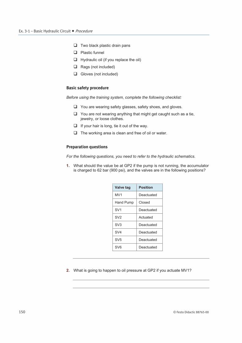
1. What should the value be at GP2 if the pump is not running, the accumulator is charged to 62 bar (900 psi), and the valves are in the following positions?
Valve tag Position
MV1 Deactuated
Hand Pump Closed
SV1 Deactuated
SV2 Actuated
SV3 Deactuated
SV4 Deactuated
SV5 Deactuated
SV6 Deactuated
2. What is going to happen to oil pressure at GP2 if you actuate MV1?

Ex. 3-1 – Basic Hydraulic Circuit Procedure
© Festo Didactic 88765-00 151
3. Pressure at PSP2 is equal to which other pressure? GP1, GP2, GB1, or GB2?
4. Why is SV1 closed in its normal position?
Setting up the nacelle
5. Make sure the main switch is off and everything is secure inside and around the nacelle.
Checking oil tank level, quality, and possible leaks
a The hydraulic unit should contain about four liters (1 gallon U.S.) of oil.
6. Actuate MV1 so that the oil in the accumulator drains into the tank. Wait approximately 10 seconds and deactuate MV1.
7. Remove the top plug (Figure 3-50).
Figure 3-50. Removing the oil tank top plug.
8. Look inside the tank and check the oil level. Is the tank level at least half full?
Yes No
If not, ask your instructor if you should add oil before starting the nacelle trainer.
9. Put the oil tank top plug back in place.

Ex. 3-1 – Basic Hydraulic Circuit Procedure
152 © Festo Didactic 88765-00
10. Do you see any unusual oil leak in, around, or under the trainer?
Yes No
11. If there is a leak, what is the possible origin of the leak?
12. If necessary, clean any spilled oil according to the procedure established in your classroom.
13. Connect the pressure gauges to ports GP1 and GP2 on the manifold.
14. Close all safety panels.
Starting the trainer
15. Notify all the people working around the nacelle that the system is about to be energized and ask your instructor for permission to power the nacelle training system.
16. Turn on the main power switch. Wait for the panel PC to boot and log into Windows. The HMI should start automatically.
17. Press the green (physical) start button under the main switch to start the system.
18. Press Start Trainer in the HMI MAIN screen.
19. At this moment, the hydraulic pump should start running and stop within a minute. Describe what you see and hear until pressures at GP1 and GP2 stabilize.
b Think about the filtration process.
Ex. 3-1 – Basic Hydraulic Circuit Procedure
© Festo Didactic 88765-00 153
20. If the ALARMS button is flashing red at this point, press it. In the opening ALARMS screen, acknowledge each current alarm. Next, press RESET ALARMS, if necessary.
21. Press MANUAL in the HMI MAIN screen
Analyzing pressure at GP1 and GP2
22. Start the DEBUG Mode in the Service – Hydraulic screen and open the safety panels.
The DEBUG Mode in the SERVICE- HYDRAULIC screen disables the alarm
caused by opening the safety panels.
23. What pressure is indicated at GP1 and GP2 at this point? Explain why it is like this.
24. What is the PSP2 pressure according to the HMI screen? Is this value similar to what you read on the GP2 pressure gauge?
25. Turn OFF the hydraulic unit and actuate valve MV1. Considering your answer to step 2, is the GP2 pressure acting as expected?
26. If you refer to the hydraulic schematic, what is limiting the oil flow out of the accumulator?
27. Deactuate valve MV1 and turn ON the hydraulic unit. Look at GP1 and GP2 pressures as the pump starts and eventually stops. Explain what is happening and identify the source of the unpleasant whistling sound.
Ex. 3-1 – Basic Hydraulic Circuit Procedure
154 © Festo Didactic 88765-00
28. Actuate valve SV1. What happens to the pressures at GP1 and GP2?
29. Keep valve SV1 actuated to stay in the oil filtering process. Actuate valve MV1 to let the pressure drop until the pump restarts (then, deactuate MV1). At this point, check the clogging (red and green) indicator during the filtration process. Does the filter need to be replaced? Explain.
30. Deactuate valve SV1.
Hand pump test
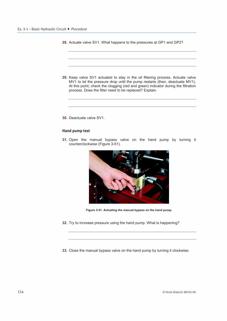
31. Open the manual bypass valve on the hand pump by turning it counterclockwise (Figure 3-51).
Figure 3-51. Actuating the manual bypass on the hand pump.
32. Try to increase pressure using the hand pump. What is happening?
33. Close the manual bypass valve on the hand pump by turning it clockwise.
Ex. 3-1 – Basic Hydraulic Circuit Procedure
© Festo Didactic 88765-00 155
34. Use the hand pump to increase pressure at GP2. Keep on pumping until pressure hits a maximum. What is the maximum pressure you can obtain and what is the limiting element?
35. Put the hand pump lever back into place, close the safety panels, and stop the DEBUG Mode.
System shutdown
36. Exit the HMI by pressing X on the top-right corner of the screen.
37. Press the Windows Start button, select Shut Down, and press OK. Wait for the system to turn off.
a You may have to reset alarms before exiting the software.
38. Use the main power switch to turn all system power off.
Lockout/tagout
For the operations to follow, the nacelle needs to be secured first.
39. Install the lockout hasp in the main switch. Next, install the student padlocks and tags in the hasp.
40. Try to turn on the main switch to verify that the system is electrically isolated. Press the start push-button to test whether the system can be energized.
a At this point, the system can be considered secure.
Identification of the hydraulic unit components
41. Open the safety panels.

Ex. 3-1 – Basic Hydraulic Circuit Procedure
156 © Festo Didactic 88765-00
42. Identify the following components and write the tag names inscribed on the manifold next to the ports they are connected to.
Table 3-1. Tag identification.
Component Tag(s) on the manifold
Hand pump
Oil filter
Accumulator
Rotor brake
Yaw brake
Hydraulic unit oil and filter change
43. If GP2 pressure is not zero, actuate valve MV1 for about 10 seconds to discharge the accumulator completely.
a If the accumulator is not discharged, that portion of the oil will not be drained.
44. Deactuate valve MV1.
45. Position a plastic drain pan under the drain plug at the bottom of the nacelle trainer (Figure 3-52).
a Use a clean pan if you plan on reusing the oil.
Figure 3-52. Positioning the pan.
46. Remove the plug on top of the oil tank.

Ex. 3-1 – Basic Hydraulic Circuit Procedure
© Festo Didactic 88765-00 157
47. Unscrew the drain plug using a 1/4-inch hex key (Figure 3-53), let the oil drain, and continue with the next steps.
Figure 3-53. Unscrewing the drain plug.
48. Put a second clean drain pan under the oil filter and use the filter wrench to unscrew the oil filter (Figure 3-54).
Figure 3-54. Removing the oil filter.
49. Either keep the oil filter or replace it with a new one. In any case, apply a thin oil coat on the filter seal you are about to use (Figure 3-55). Oil will help screwing the filter smoothly and preserve its leak tightness. If you are reusing the same filter, make sure it is still in good condition (seal and body).

Ex. 3-1 – Basic Hydraulic Circuit Procedure
158 © Festo Didactic 88765-00
Figure 3-55. Coating the filter seal with oil.
50. Screw the new oil filter in place using only your hands.
51. Take the drain plug, make sure the seal is in good condition, and screw it back into place.
52. Put the plastic funnel on top of the tank.
53. Fill the tank with about four liters (one gallon U.S.) of oil (Figure 3-56).
Figure 3-56. Filling up the hydraulic oil tank.
54. Put the plug back on top of the oil tank.
55. Clean the area and close the safety panels.
Checking for leaks
56. Ask everyone to remove their individual padlock and tag. Next, remove the hasp from the main switch.

Ex. 3-1 – Basic Hydraulic Circuit Conclusion
© Festo Didactic 88765-00 159
57. Notify all the people working around the nacelle that the system is about to be energized and ask your instructor for permission to power the nacelle training system.
58. Turn on the main power switch. Wait for the panel PC to boot and log into Windows. The HMI should start automatically.
59. Press the green (physical) start button under the main switch to start the system.
60. Press Start Trainer in the HMI MAIN screen. The hydraulic pump should start to raise system pressure.
61. Do you see any unusual oil leak in, around, or under the trainer following the oil and filter change (check specifically around the oil filter and the drain plug)? Explain.
Yes No
62. If oil is leaking, talk to your instructor about it and make sure you take corrective action before the end of the lab.
End of the procedure
63. Exit the HMI by pressing X on the top-right corner of the screen.
64. Press the Windows Start button, select Shut Down, and press OK. Wait for the system to turn off.
a You may have to reset alarms before exiting the software.
65. Use the main power switch to turn all system power off.
66. Clean the accessories that were used for the oil change.
In this exercise, you became more familiar with the hydraulic unit and schematics. You identified components, measured pressure, and changed the state of some valves via the HMI. Finally, you did some maintenance work by changing the hydraulic oil and oil filter.
CONCLUSION

Ex. 3-1 – Basic Hydraulic Circuit Review Questions
160 © Festo Didactic 88765-00
1. Name the main components that make up the power unit.
2. What component prevents excess pressure from developing in the power unit?
3. Why would you want to use a manifold block in a hydraulic system?
4. What is the system accumulator loaded with?
5. Which of the two system brakes requires oil pressure to be applied?
REVIEW QUESTIONS


![[PPT]Simple hydraulic circuit (Pictorial view) · Web viewSimple hydraulic circuit (Pictorial view) * * Simple hydraulic circuit (Semi pictorial view) * Simple hydraulic circuit (Symbolic](https://img.dokumen.tips/doc/110x75/5ac995037f8b9a6b578d2677/pptsimple-hydraulic-circuit-pictorial-view-viewsimple-hydraulic-circuit-pictorial.jpg)