Embed Size (px)
Citation preview
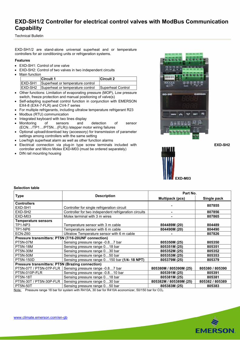
EXD-SH1/2 Controller for electrical control valves with ModBus Communication Capability Technical Bulletin
www.climate.emerson.com/en-gb
EXD-SH1/2 are stand-alone universal superheat and or temperature controllers for air conditioning units or refrigeration systems.
Features • EXD-SH1: Control of one valve • EXD-SH2: Control of two valves in two independent circuits • Main function
Circuit 1 Circuit 2 EXD-SH1 Superheat or temperature control EXD-SH2 Superheat or temperature control Superheat Control
• Other functions: Limitation of evaporating pressure (MOP), Low pressure switch, freeze protection and manual positioning of valve(s)
• Self-adapting superheat control function in conjunction with EMERSON EX4-8 (EX4-7-FLR) and CV4-7 series
• For multiple refrigerants, including ultralow temperature refrigerant R23 • Modbus (RTU) communication • Integrated keyboard with two lines display • Monitoring of sensors and detection of sensor
(ECN…/TP1…/PT5N…(FLR)) /stepper motor wiring failures • Optional upload/download key (accessory) for transmission of parameter
settings among controllers with the same setting • Low/high superheat alarm as well as other function alarms • Electrical connection via plug-in type screw terminals included with
controller and Micro Molex EXD-M03 (must be ordered separately) • DIN rail mounting housing
EXD-SH2
EXD-M03
Selection table
Type Description Part No.
Multipack (pcs) Single pack Controllers EXD-SH1
Controller for single refrigeration circuit - 807855
EXD-SH2 Controller for two independent refrigeration circuits - 807856 EXD-M03 Molex terminal with 3 m wires - 807865 Temperature sensors TP1-NP3 Temperature sensor with 3 m cable 804489M (20) 804489 TP1-NP6 Temperature sensor with 6 m cable 804490M (20) 804490 ECN-Z60 Ultralow Temperature sensor with 6 m cable - 807826 Pressure transmitters: PT5N (7/16-20UNF connection) PT5N-07M Sensing pressure range -0.8…7 bar 805350M (25) 805350 PT5N-18M Sensing pressure range 0…18 bar 805351M (25) 805351 PT5N-30M Sensing pressure range 0…30 bar 805352M (25) 805352 PT5N-50M Sensing pressure range 0…50 bar 805353M (25) 805353 PT5N-150D Sensing pressure range 0…150 bar (1/4- 18 NPT) 805379M (25) 805379 Pressure transmitters: PT5N (Brazing connection) PT5N-07T / PT5N-07P-FLR Sensing pressure range -0.8…7 bar 805380M / 805390M (25) 805380 / 805390 PT5N-010P-FLR Sensing pressure range -0.8…10 bar 805391M (25) 805391 PT5N-18T Sensing pressure range 0…18 bar 805381M (25) 805381 PT5N-30T / PT5N-30P-FLR Sensing pressure range 0…30 bar 805382M / 805389M (25) 805382 / 805389 PT5N-50T Sensing pressure range 0…50 bar 805383M (25) 805383
Note: Pressure range 18 bar for system with R410A, 30 bar for R410A economizer, 50/150 bar for CO2
EXD-SH1/2 Controller for electrical control valves with ModBus Communication Capability
2 EXD-SH12_TB_EN_1120_R09.docx
Accessories
Type Description Part No.
Multipack (20 pieces) Single pack M12 Plug and cable for pressure transmitters PT5N(FLR) PT4-M15 1.5 m 804803M 804803 PT4-M30 3.0 m 804804M 804804 PT4-M60 6.0 m 804805M 804805 PT4-M60 FLR 6.0 m - 804806 Uninterruptible Power supply ECP-024 Backup battery with two outputs for two controllers - 804558 K09-P00 Electrical Terminal Kit for ECP-024 - 804560 EXD-PM Super cap for only EXD-SH1
(two pieces of EXD-PM required for one EXD-SH2) - 807854
Note: Warning -Flammable refrigerants: EXD-SH1/2 (EXD-PM, ECP-024) has a potential ignition source and does not comply with ATEX requirements. Installation only in non-explosive environment. For flammable refrigerants only use valves and accessories approved for it!
Description of functions Controllers are featured with a main function as superheat controller or temperature controller. The main function is selectable.
Superheat control of evaporators or economizers This function requires the connection of temperature sensor(s) as well as pressure transmitters(s). The other functions are:
• MOP control: enables the limitation of saturated temperature of suction line (outlet of evaporator/economizer) • Low pressure behaves similar to low pressure switch including alarm conditions • Freeze protection is based on saturated temperature from converting measuring suction pressure. It provides alarm condition
below certain adjusted temperature.
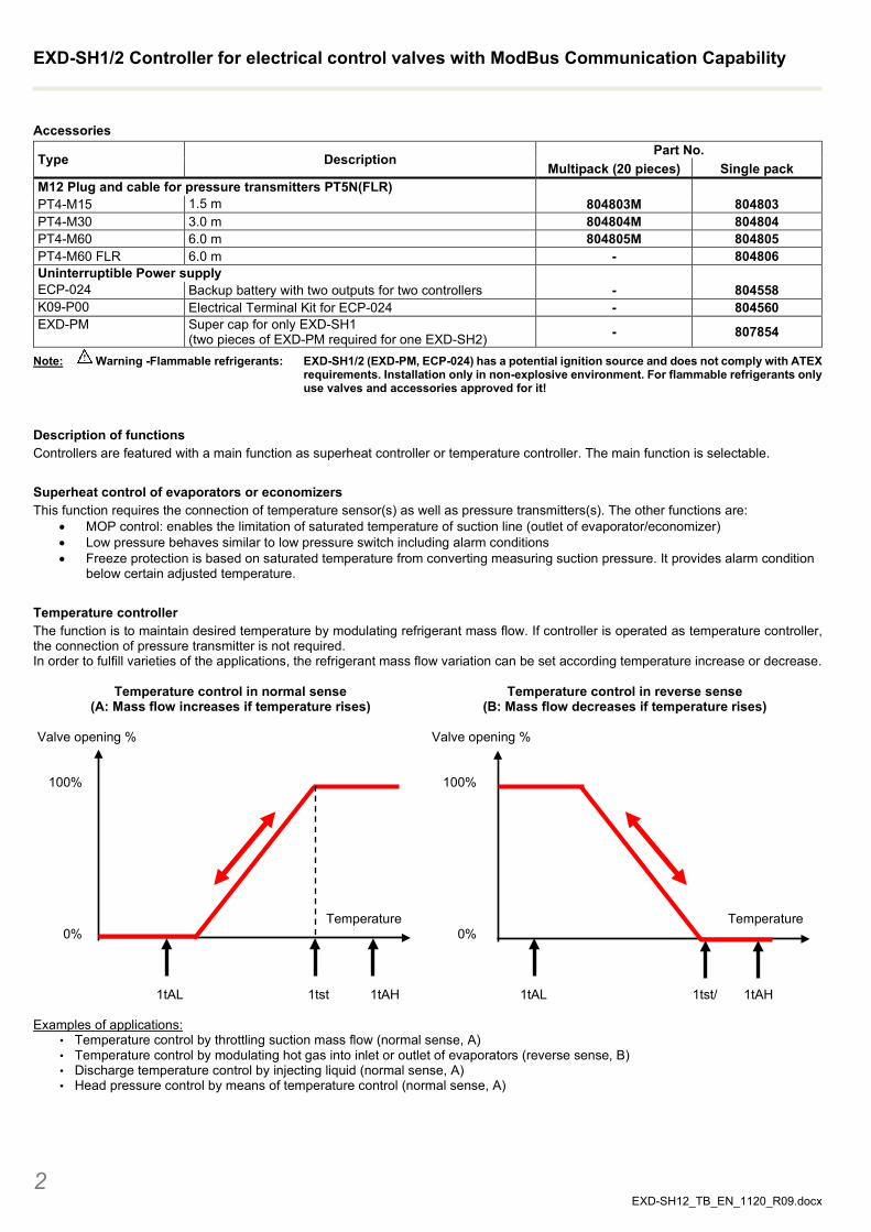
Temperature controller The function is to maintain desired temperature by modulating refrigerant mass flow. If controller is operated as temperature controller, the connection of pressure transmitter is not required. In order to fulfill varieties of the applications, the refrigerant mass flow variation can be set according temperature increase or decrease.
Temperature control in normal sense (A: Mass flow increases if temperature rises)
Valve opening % 100% Temperature 0%
1tAL 1tst 1tAH
Temperature control in reverse sense (B: Mass flow decreases if temperature rises)
Valve opening % 100% Temperature 0% 1tAL 1tst/ 1tAH
Examples of applications:
• Temperature control by throttling suction mass flow (normal sense, A) • Temperature control by modulating hot gas into inlet or outlet of evaporators (reverse sense, B) • Discharge temperature control by injecting liquid (normal sense, A) • Head pressure control by means of temperature control (normal sense, A)
EXD-SH1/2 Controller for electrical control valves with ModBus Communication Capability
3 EXD-SH12_TB_EN_1120_R09.docx
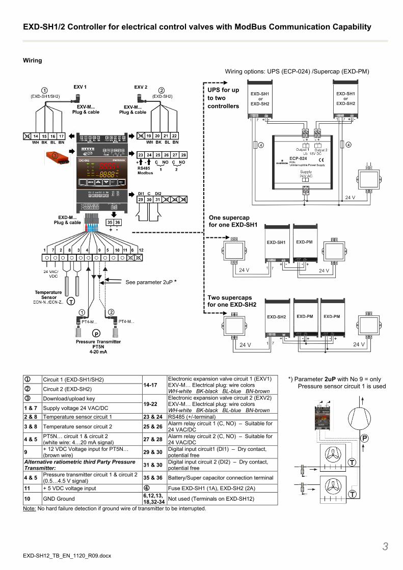
Wiring
Wiring options: UPS (ECP-024) /Supercap (EXD-PM)
Circuit 1 (EXD-SH1/SH2)
14-17 Electronic expansion valve circuit 1 (EXV1) EXV-M… Electrical plug: wire colors WH-white BK-black BL-blue BN-brown
*) Parameter 2uP with No 9 = only Pressure sensor circuit 1 is used Circuit 2 (EXD-SH2)
Download/upload key 19-22
Electronic expansion valve circuit 2 (EXV2) EXV-M… Electrical plug: wire colors WH-white BK-black BL-blue BN-brown
1 & 7 Supply voltage 24 VAC/DC 2 & 8 Temperature sensor circuit 1 23 & 24 RS485 (+/-terminal)
3 & 8 Temperature sensor circuit 2 25 & 26 Alarm relay circuit 1 (C, NO) – Suitable for 24 VAC/DC
4 & 5 PT5N… circuit 1 & circuit 2 (white wire: 4…20 mA signal) 27 & 28 Alarm relay circuit 2 (C, NO) – Suitable for
24 VAC/DC
9 + 12 VDC Voltage input for PT5N… (brown wire) 29 & 30 Digital input circuit1 (DI1) – Dry contact,
potential free Alternative ratiometric third Party Pressure Transmitter: 31 & 30 Digital input circuit 2 (DI2) – Dry contact,
potential free
4 & 5 Pressure transmitter circuit 1 & circuit 2 (0.5…4.5 V signal) 35 & 36 Battery/Super capacitor connection terminal
11 + 5 VDC voltage input Fuse EXD-SH1 (1A), EXD-SH2 (2A)
10 GND Ground 6,12,13, 18,32-34 Not used (Terminals on EXD-SH12)
Note: No hard failure detection if ground wire of transmitter to be interrupted.
T
UPS for up to two controllers
One supercap for one EXD-SH1
See parameter 2uP *
P
Two supercaps for one EXD-SH2
EXD-SH1/2 Controller for electrical control valves with ModBus Communication Capability
4 EXD-SH12_TB_EN_1120_R09.docx
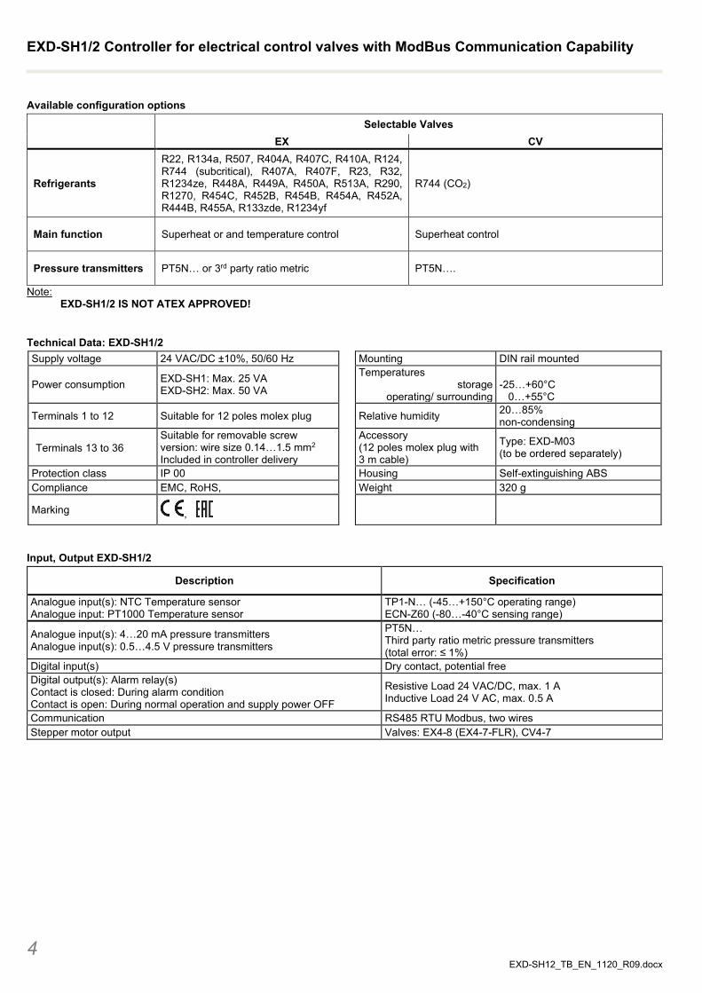
Available configuration options
Selectable Valves EX CV
Refrigerants
R22, R134a, R507, R404A, R407C, R410A, R124, R744 (subcritical), R407A, R407F, R23, R32, R1234ze, R448A, R449A, R450A, R513A, R290, R1270, R454C, R452B, R454B, R454A, R452A, R444B, R455A, R133zde, R1234yf
R744 (CO2)
Main function Superheat or and temperature control Superheat control
Pressure transmitters PT5N… or 3rd party ratio metric PT5N….
Note: EXD-SH1/2 IS NOT ATEX APPROVED!
Technical Data: EXD-SH1/2 Supply voltage 24 VAC/DC ±10%, 50/60 Hz Mounting DIN rail mounted
Power consumption EXD-SH1: Max. 25 VA EXD-SH2: Max. 50 VA
Temperatures storage
operating/ surrounding
-25…+60°C 0…+55°C
Terminals 1 to 12 Suitable for 12 poles molex plug Relative humidity 20…85% non-condensing
Terminals 13 to 36 Suitable for removable screw version: wire size 0.14…1.5 mm2 Included in controller delivery
Accessory (12 poles molex plug with 3 m cable)
Type: EXD-M03 (to be ordered separately)
Protection class IP 00 Housing Self-extinguishing ABS Compliance EMC, RoHS, Weight 320 g
Marking ,
Input, Output EXD-SH1/2
Description Specification
Analogue input(s): NTC Temperature sensor Analogue input: PT1000 Temperature sensor
TP1-N… (-45…+150°C operating range) ECN-Z60 (-80…-40°C sensing range)
Analogue input(s): 4…20 mA pressure transmitters Analogue input(s): 0.5…4.5 V pressure transmitters
PT5N… Third party ratio metric pressure transmitters (total error: ≤ 1%)
Digital input(s) Dry contact, potential free Digital output(s): Alarm relay(s) Contact is closed: During alarm condition Contact is open: During normal operation and supply power OFF
Resistive Load 24 VAC/DC, max. 1 A Inductive Load 24 V AC, max. 0.5 A
Communication RS485 RTU Modbus, two wires Stepper motor output Valves: EX4-8 (EX4-7-FLR), CV4-7
EXD-SH1/2 Controller for electrical control valves with ModBus Communication Capability
5 EXD-SH12_TB_EN_1120_R09.docx
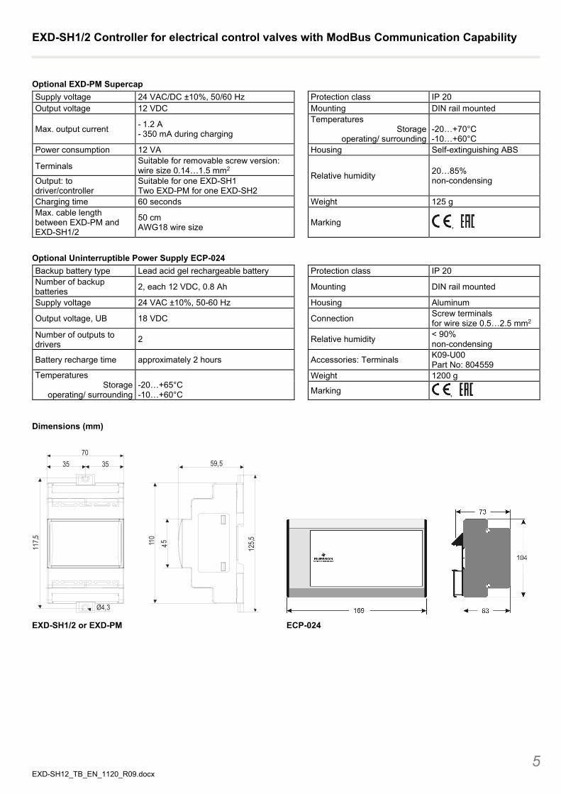
Optional EXD-PM Supercap Supply voltage 24 VAC/DC ±10%, 50/60 Hz Protection class IP 20 Output voltage 12 VDC Mounting DIN rail mounted
Max. output current - 1.2 A - 350 mA during charging
Temperatures Storage
operating/ surrounding
-20…+70°C -10…+60°C
Power consumption 12 VA Housing Self-extinguishing ABS
Terminals Suitable for removable screw version: wire size 0.14…1.5 mm2
Relative humidity 20…85% non-condensing Output: to
driver/controller Suitable for one EXD-SH1 Two EXD-PM for one EXD-SH2
Charging time 60 seconds Weight 125 g Max. cable length between EXD-PM and EXD-SH1/2
50 cm AWG18 wire size Marking ,
Optional Uninterruptible Power Supply ECP-024 Backup battery type Lead acid gel rechargeable battery Protection class IP 20 Number of backup batteries 2, each 12 VDC, 0.8 Ah Mounting DIN rail mounted
Supply voltage 24 VAC ±10%, 50-60 Hz Housing Aluminum
Output voltage, UB 18 VDC Connection Screw terminals for wire size 0.5…2.5 mm2
Number of outputs to drivers 2 Relative humidity < 90%
non-condensing
Battery recharge time approximately 2 hours Accessories: Terminals K09-U00 Part No: 804559
Temperatures Storage
operating/ surrounding
-20…+65°C -10…+60°C
Weight 1200 g
Marking ,
Dimensions (mm)
EXD-SH1/2 or EXD-PM ECP-024
703535
117,5
Ø4,3
110
125,545
59,5
EXD-SH1/2 Controller for electrical control valves with ModBus Communication Capability
6 EXD-SH12_TB_EN_1120_R09.docx
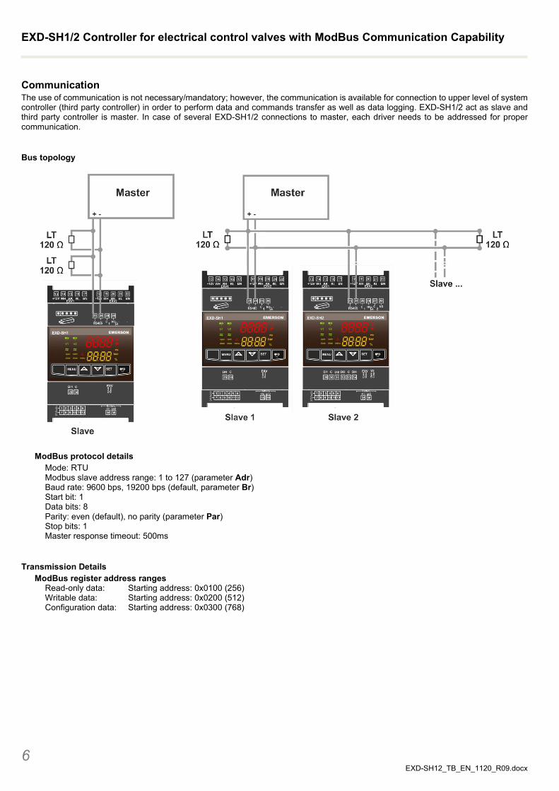
Communication The use of communication is not necessary/mandatory; however, the communication is available for connection to upper level of system controller (third party controller) in order to perform data and commands transfer as well as data logging. EXD-SH1/2 act as slave and third party controller is master. In case of several EXD-SH1/2 connections to master, each driver needs to be addressed for proper communication.
Bus topology
ModBus protocol details
Mode: RTU Modbus slave address range: 1 to 127 (parameter Adr) Baud rate: 9600 bps, 19200 bps (default, parameter Br) Start bit: 1 Data bits: 8 Parity: even (default), no parity (parameter Par) Stop bits: 1 Master response timeout: 500ms
Transmission Details ModBus register address ranges
Read-only data: Starting address: 0x0100 (256) Writable data: Starting address: 0x0200 (512) Configuration data: Starting address: 0x0300 (768)
EXD-SH1/2 Controller for electrical control valves with ModBus Communication Capability
7 EXD-SH12_TB_EN_1120_R09.docx
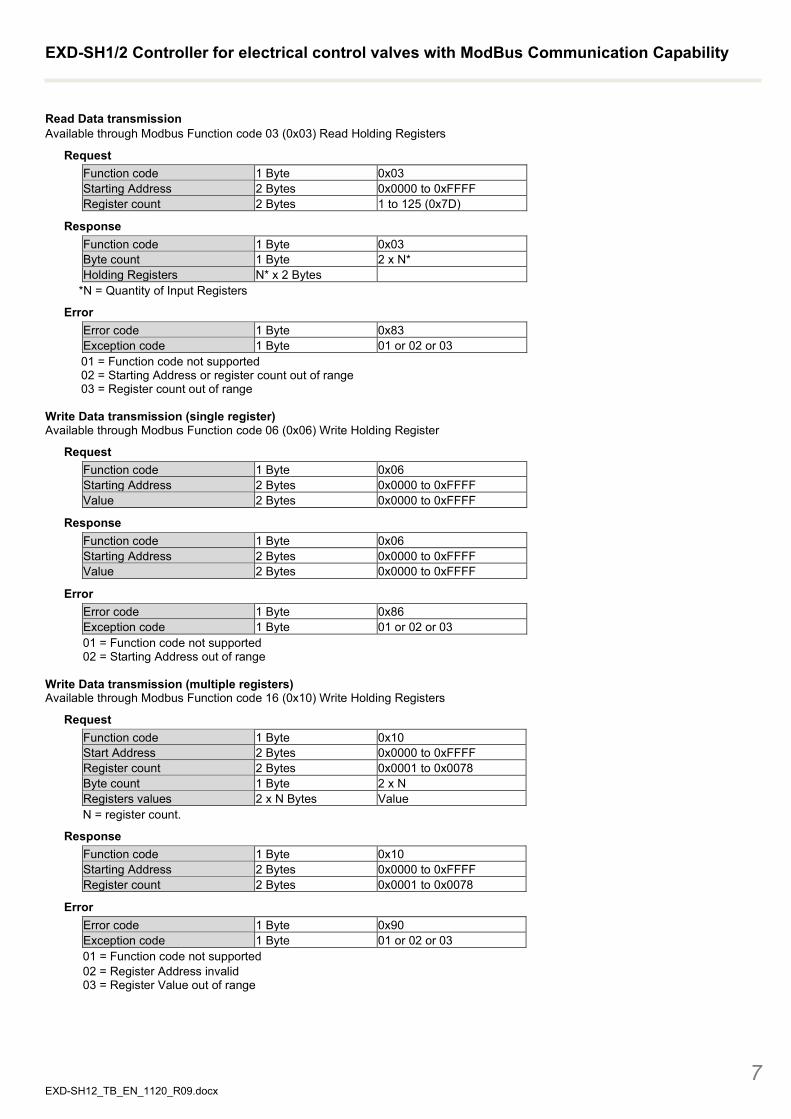
Read Data transmission Available through Modbus Function code 03 (0x03) Read Holding Registers
Request Function code 1 Byte 0x03 Starting Address 2 Bytes 0x0000 to 0xFFFF Register count 2 Bytes 1 to 125 (0x7D)
Response Function code 1 Byte 0x03 Byte count 1 Byte 2 x N* Holding Registers N* x 2 Bytes
*N = Quantity of Input Registers
Error Error code 1 Byte 0x83 Exception code 1 Byte 01 or 02 or 03 01 = Function code not supported 02 = Starting Address or register count out of range 03 = Register count out of range
Write Data transmission (single register) Available through Modbus Function code 06 (0x06) Write Holding Register
Request Function code 1 Byte 0x06 Starting Address 2 Bytes 0x0000 to 0xFFFF Value 2 Bytes 0x0000 to 0xFFFF
Response Function code 1 Byte 0x06 Starting Address 2 Bytes 0x0000 to 0xFFFF Value 2 Bytes 0x0000 to 0xFFFF
Error Error code 1 Byte 0x86 Exception code 1 Byte 01 or 02 or 03 01 = Function code not supported 02 = Starting Address out of range
Write Data transmission (multiple registers) Available through Modbus Function code 16 (0x10) Write Holding Registers
Request Function code 1 Byte 0x10 Start Address 2 Bytes 0x0000 to 0xFFFF Register count 2 Bytes 0x0001 to 0x0078 Byte count 1 Byte 2 x N Registers values 2 x N Bytes Value N = register count.
Response Function code 1 Byte 0x10 Starting Address 2 Bytes 0x0000 to 0xFFFF Register count 2 Bytes 0x0001 to 0x0078
Error Error code 1 Byte 0x90 Exception code 1 Byte 01 or 02 or 03 01 = Function code not supported 02 = Register Address invalid 03 = Register Value out of range
EXD-SH1/2 Controller for electrical control valves with ModBus Communication Capability
8 EXD-SH12_TB_EN_1120_R09.docx
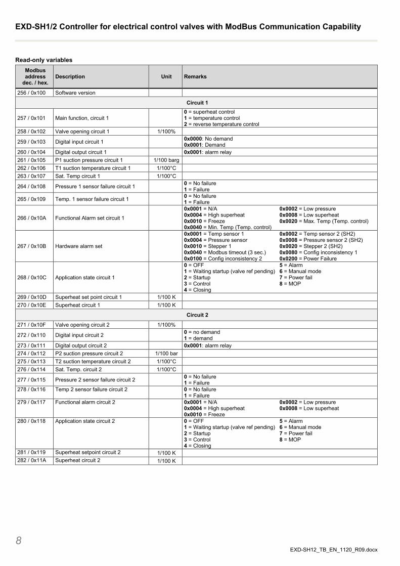
Read-only variables Modbus address
dec. / hex. Description Unit Remarks
256 / 0x100 Software version
Circuit 1
257 / 0x101 Main function, circuit 1 0 = superheat control 1 = temperature control 2 = reverse temperature control
258 / 0x102 Valve opening circuit 1 1/100%
259 / 0x103 Digital input circuit 1 0x0000: No demand 0x0001: Demand
260 / 0x104 Digital output circuit 1 0x0001: alarm relay 261 / 0x105 P1 suction pressure circuit 1 1/100 barg 262 / 0x106 T1 suction temperature circuit 1 1/100°C 263 / 0x107 Sat. Temp circuit 1 1/100°C
264 / 0x108 Pressure 1 sensor failure circuit 1 0 = No failure 1 = Failure
265 / 0x109 Temp. 1 sensor failure circuit 1 0 = No failure 1 = Failure
266 / 0x10A Functional Alarm set circuit 1
0x0001 = N/A 0x0002 = Low pressure 0x0004 = High superheat 0x0008 = Low superheat 0x0010 = Freeze 0x0020 = Max. Temp (Temp. control) 0x0040 = Min. Temp (Temp. control)
267 / 0x10B Hardware alarm set
0x0001 = Temp sensor 1 0x0002 = Temp sensor 2 (SH2) 0x0004 = Pressure sensor 0x0008 = Pressure sensor 2 (SH2) 0x0010 = Stepper 1 0x0020 = Stepper 2 (SH2) 0x0040 = Modbus timeout (3 sec.) 0x0080 = Config inconsistency 1 0x0100 = Config inconsistency 2 0x0200 = Power Failure
268 / 0x10C Application state circuit 1
0 = OFF 5 = Alarm 1 = Waiting startup (valve ref pending) 6 = Manual mode 2 = Startup 7 = Power fail 3 = Control 8 = MOP 4 = Closing
269 / 0x10D Superheat set point circuit 1 1/100 K 270 / 0x10E Superheat circuit 1 1/100 K
Circuit 2
271 / 0x10F Valve opening circuit 2 1/100%
272 / 0x110 Digital input circuit 2 0 = no demand 1 = demand
273 / 0x111 Digital output circuit 2 0x0001: alarm relay 274 / 0x112 P2 suction pressure circuit 2 1/100 bar 275 / 0x113 T2 suction temperature circuit 2 1/100°C 276 / 0x114 Sat. Temp. circuit 2 1/100°C
277 / 0x115 Pressure 2 sensor failure circuit 2 0 = No failure 1 = Failure
278 / 0x116 Temp 2 sensor failure circuit 2 0 = No failure 1 = Failure
279 / 0x117 Functional alarm circuit 2
0x0001 = N/A 0x0002 = Low pressure 0x0004 = High superheat 0x0008 = Low superheat 0x0010 = Freeze
280 / 0x118 Application state circuit 2
0 = OFF 5 = Alarm 1 = Waiting startup (valve ref pending) 6 = Manual mode 2 = Startup 7 = Power fail 3 = Control 8 = MOP 4 = Closing
281 / 0x119 Superheat setpoint circuit 2 1/100 K 282 / 0x11A Superheat circuit 2 1/100 K
EXD-SH1/2 Controller for electrical control valves with ModBus Communication Capability
9 EXD-SH12_TB_EN_1120_R09.docx
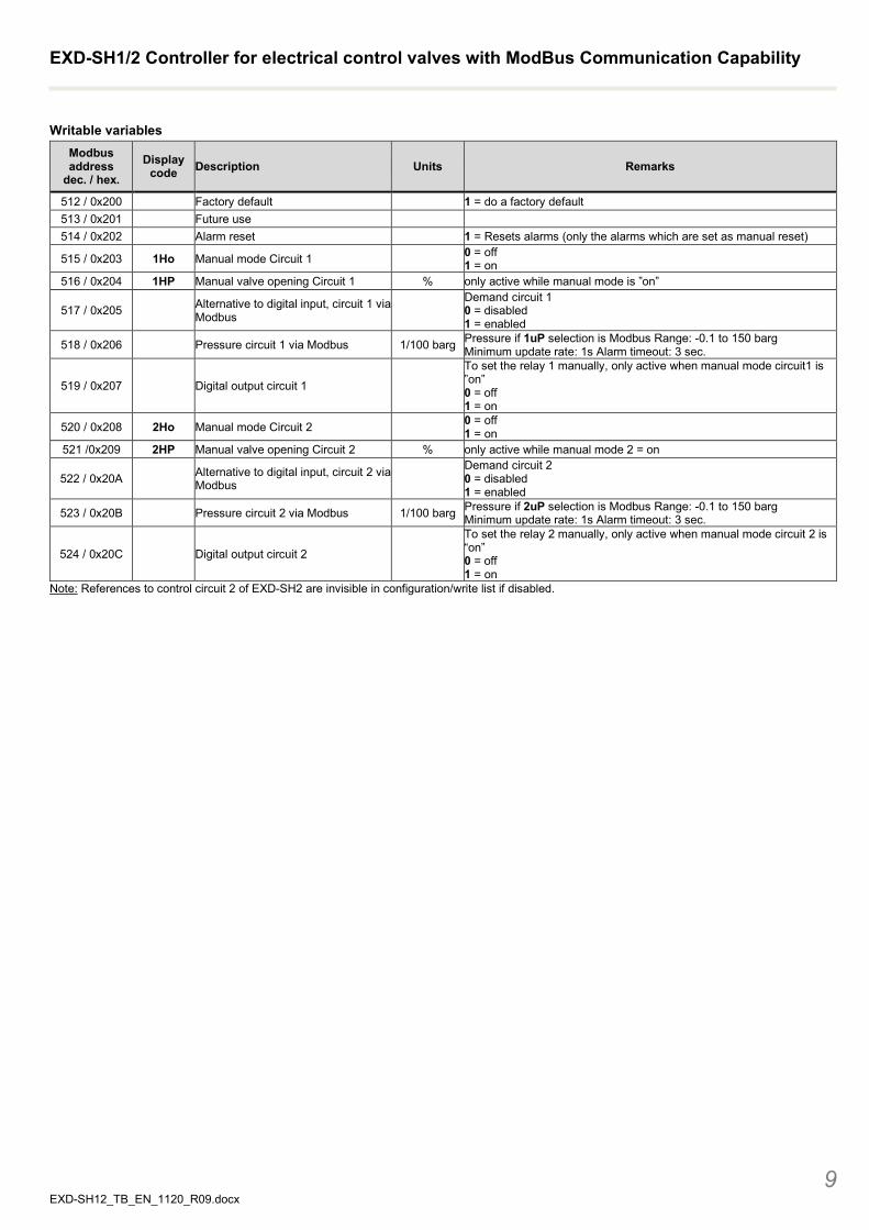
Writable variables Modbus address
dec. / hex. Display
code Description Units Remarks
512 / 0x200 Factory default 1 = do a factory default 513 / 0x201 Future use 514 / 0x202 Alarm reset 1 = Resets alarms (only the alarms which are set as manual reset)
515 / 0x203 1Ho Manual mode Circuit 1 0 = off 1 = on
516 / 0x204 1HP Manual valve opening Circuit 1 % only active while manual mode is ”on”
517 / 0x205 Alternative to digital input, circuit 1 via Modbus
Demand circuit 1 0 = disabled 1 = enabled
518 / 0x206 Pressure circuit 1 via Modbus 1/100 barg Pressure if 1uP selection is Modbus Range: -0.1 to 150 barg Minimum update rate: 1s Alarm timeout: 3 sec.
519 / 0x207 Digital output circuit 1
To set the relay 1 manually, only active when manual mode circuit1 is ”on” 0 = off 1 = on
520 / 0x208 2Ho Manual mode Circuit 2 0 = off 1 = on
521 /0x209 2HP Manual valve opening Circuit 2 % only active while manual mode 2 = on
522 / 0x20A Alternative to digital input, circuit 2 via Modbus
Demand circuit 2 0 = disabled 1 = enabled
523 / 0x20B Pressure circuit 2 via Modbus 1/100 barg Pressure if 2uP selection is Modbus Range: -0.1 to 150 barg Minimum update rate: 1s Alarm timeout: 3 sec.
524 / 0x20C Digital output circuit 2
To set the relay 2 manually, only active when manual mode circuit 2 is “on” 0 = off 1 = on
Note: References to control circuit 2 of EXD-SH2 are invisible in configuration/write list if disabled.
EXD-SH1/2 Controller for electrical control valves with ModBus Communication Capability
10 EXD-SH12_TB_EN_1120_R09.docx
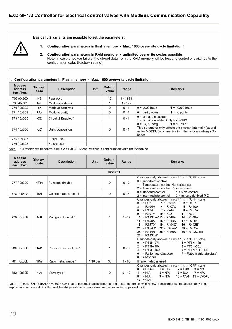
Basically 2 variants are possible to set the parameters:
1. Configuration parameters in flash memory - Max. 1000 overwrite cycle limitation!
2. Configuration parameters in RAM memory - unlimited overwrite cycles possible Note: In case of power failure, the stored data from the RAM memory will be lost and controller switches to the configuration data. (Factory setting)
1. Configuration parameters In Flash memory - Max. 1000 overwrite cycle limitation Modbus address
dec. / hex. Display
code Description Unit Default value Range Remarks
768 /0x300 H5 Password 12 1 - 1999 769 /0x301 Adr Modbus address 1 1 - 127 770 / 0x302 br Modbus baudrate 0 0 - 1 0 = 9600 baud 1 = 19200 baud 771 / 0x303 PAr Modbus parity 0 0 - 1 0 = parity even 1 = no parity
773 / 0x305 -C2 Circuit 2 Enabled2 1 0 - 1 0 = circuit 2 disabled 1 = circuit 2 enabled Only EXD-SH2
774 / 0x306 -uC Units conversion 0 0 - 1
0 = °C, K, barg 1 = °F, psig This parameter only affects the display. Internally (as well as for MODBUS communication) the units are always SI-based.
775 / 0x307 Future use 776 / 0x308 Future use
Note: 2) References to control circuit 2 if EXD-SH2 are invisible in configuration/write list if disabled
Modbus address
dec. / hex. Display
code Description Unit Default value Range Remarks
Circuit 1
777 / 0x309 1Fct Function circuit 1 0 0 - 2
Changes only allowed if circuit 1 is in “OFF” state 0 = superheat control 1 = Temperature control Normal sense 2 = Temperature control Reverse sense
778 / 0x30A 1u4 Control mode circuit 1 0 0 - 3 0 = standard control 1 = slow control 2 = intermediate control 3 = adjustable fixed PID
779 / 0x30B 1u0 Refrigerant circuit 1 1 0 –27
Changes only allowed if circuit 1 is in “OFF” state 0 = R22 1 = R134a 2 = R507 3 = R404A 4 = R407C 5 = R410A 6 = R124 7 = R744 8 = R407A 9 = R407F 10 = R23 11 = R32* 12 = R1234ze* 13 = R448A 14 = R449A 15 = R450A 16 = R513A 17 = R290* 18 = R1270* 19 = R454C* 20 = R452B* 21 = R454B* 22 = R454A* 23 = R452A 24 = R444B* 25 = R455A * 26 = R1233zde* 27 = R1234yf*
780 / 0x30C 1uP Pressure sensor type 1 1 0 - 8
Changes only allowed if circuit 1 is in “OFF” state 0 = PT5N-07x 1 = PT5N-18x 2 = PT5N-30x 3 = PT5N-50x 4 = PT5N-150 5 = PT5N-10P-FLR 6 = Ratio metric(gauge) 7 = Ratio metric(absolute) 8 = Modbus
781 / 0x30D 1Prr Ratio metric range 1 1/10 bar 30 3 - 60 If ratio metric is used
782 / 0x30E 1ut Valve type 1 0 0 - 12
Changes only allowed if circuit 1 is in “OFF” state 0 = EX4-6 1 = EX7 2 = EX8 3 = N/A 4 = N/A 5 = N/A 6 = N/A 7 = N/A 8 = N/A 9 = N/A 10 = CV4 11 = CV5+6 12 = CV7
Note: *) EXD-SH1/2 (EXD-PM, ECP-024) has a potential ignition source and does not comply with ATEX requirements. Installation only in non-explosive environment. For flammable refrigerants only use valves and accessories approved for it!
EXD-SH1/2 Controller for electrical control valves with ModBus Communication Capability
11 EXD-SH12_TB_EN_1120_R09.docx
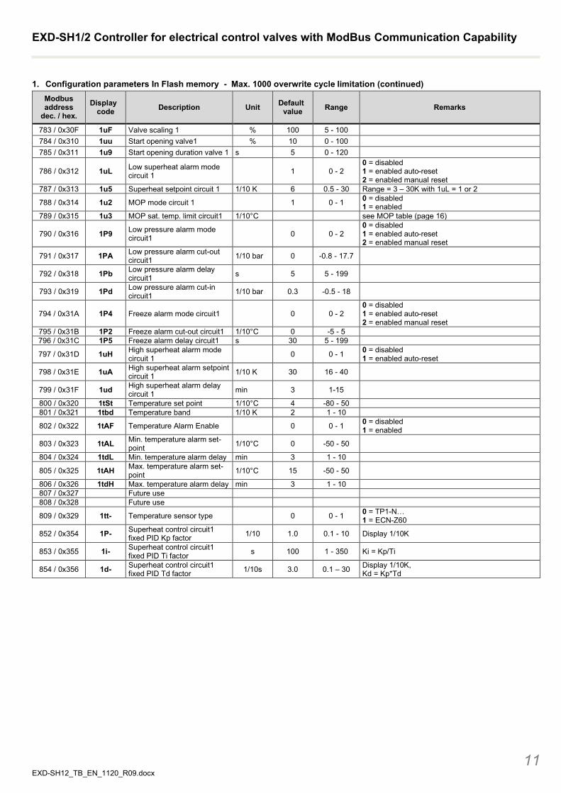
1. Configuration parameters In Flash memory - Max. 1000 overwrite cycle limitation (continued) Modbus address
dec. / hex. Display
code Description Unit Default value Range Remarks
783 / 0x30F 1uF Valve scaling 1 % 100 5 - 100 784 / 0x310 1uu Start opening valve1 % 10 0 - 100 785 / 0x311 1u9 Start opening duration valve 1 s 5 0 - 120
786 / 0x312 1uL Low superheat alarm mode circuit 1 1 0 - 2
0 = disabled 1 = enabled auto-reset 2 = enabled manual reset
787 / 0x313 1u5 Superheat setpoint circuit 1 1/10 K 6 0.5 - 30 Range = 3 – 30K with 1uL = 1 or 2
788 / 0x314 1u2 MOP mode circuit 1 1 0 - 1 0 = disabled 1 = enabled
789 / 0x315 1u3 MOP sat. temp. limit circuit1 1/10°C see MOP table (page 16)
790 / 0x316 1P9 Low pressure alarm mode circuit1 0 0 - 2
0 = disabled 1 = enabled auto-reset 2 = enabled manual reset
791 / 0x317 1PA Low pressure alarm cut-out circuit1 1/10 bar 0 -0.8 - 17.7
792 / 0x318 1Pb Low pressure alarm delay circuit1 s 5 5 - 199
793 / 0x319 1Pd Low pressure alarm cut-in circuit1 1/10 bar 0.3 -0.5 - 18
794 / 0x31A 1P4 Freeze alarm mode circuit1 0 0 - 2 0 = disabled 1 = enabled auto-reset 2 = enabled manual reset
795 / 0x31B 1P2 Freeze alarm cut-out circuit1 1/10°C 0 -5 - 5 796 / 0x31C 1P5 Freeze alarm delay circuit1 s 30 5 - 199
797 / 0x31D 1uH High superheat alarm mode circuit 1 0 0 - 1 0 = disabled
1 = enabled auto-reset
798 / 0x31E 1uA High superheat alarm setpoint circuit 1 1/10 K 30 16 - 40
799 / 0x31F 1ud High superheat alarm delay circuit 1 min 3 1-15
800 / 0x320 1tSt Temperature set point 1/10°C 4 -80 - 50 801 / 0x321 1tbd Temperature band 1/10 K 2 1 - 10
802 / 0x322 1tAF Temperature Alarm Enable 0 0 - 1 0 = disabled 1 = enabled
803 / 0x323 1tAL Min. temperature alarm set-point 1/10°C 0 -50 - 50
804 / 0x324 1tdL Min. temperature alarm delay min 3 1 - 10
805 / 0x325 1tAH Max. temperature alarm set- point 1/10°C 15 -50 - 50
806 / 0x326 1tdH Max. temperature alarm delay min 3 1 - 10 807 / 0x327 Future use 808 / 0x328 Future use
809 / 0x329 1tt- Temperature sensor type 0 0 - 1 0 = TP1-N… 1 = ECN-Z60
852 / 0x354 1P- Superheat control circuit1 fixed PID Kp factor 1/10 1.0 0.1 - 10 Display 1/10K
853 / 0x355 1i- Superheat control circuit1 fixed PID Ti factor s 100 1 - 350 Ki = Kp/Ti
854 / 0x356 1d- Superheat control circuit1 fixed PID Td factor 1/10s 3.0 0.1 – 30 Display 1/10K,
Kd = Kp*Td
EXD-SH1/2 Controller for electrical control valves with ModBus Communication Capability
12 EXD-SH12_TB_EN_1120_R09.docx
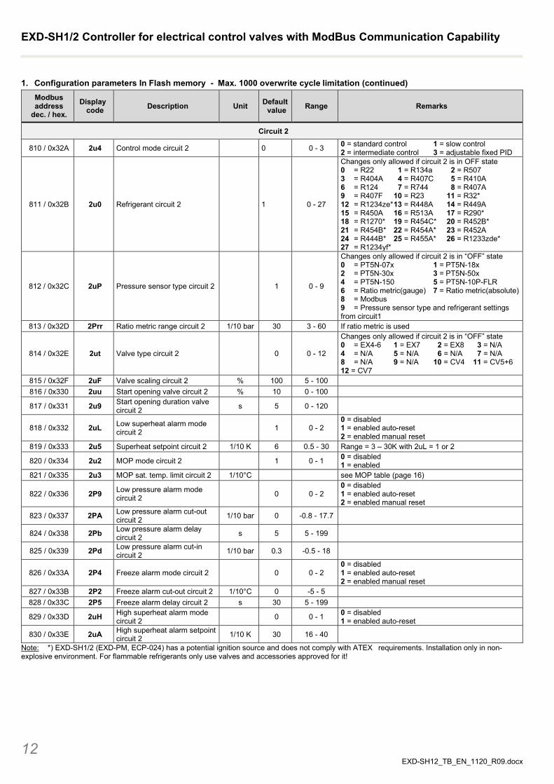
1. Configuration parameters In Flash memory - Max. 1000 overwrite cycle limitation (continued) Modbus address
dec. / hex. Display
code Description Unit Default value Range Remarks
Circuit 2
810 / 0x32A 2u4 Control mode circuit 2 0 0 - 3 0 = standard control 1 = slow control 2 = intermediate control 3 = adjustable fixed PID
811 / 0x32B 2u0 Refrigerant circuit 2 1 0 - 27
Changes only allowed if circuit 2 is in OFF state 0 = R22 1 = R134a 2 = R507 3 = R404A 4 = R407C 5 = R410A 6 = R124 7 = R744 8 = R407A 9 = R407F 10 = R23 11 = R32* 12 = R1234ze* 13 = R448A 14 = R449A 15 = R450A 16 = R513A 17 = R290* 18 = R1270* 19 = R454C* 20 = R452B* 21 = R454B* 22 = R454A* 23 = R452A 24 = R444B* 25 = R455A * 26 = R1233zde* 27 = R1234yf*
812 / 0x32C 2uP Pressure sensor type circuit 2 1 0 - 9
Changes only allowed if circuit 2 is in “OFF” state 0 = PT5N-07x 1 = PT5N-18x 2 = PT5N-30x 3 = PT5N-50x 4 = PT5N-150 5 = PT5N-10P-FLR 6 = Ratio metric(gauge) 7 = Ratio metric(absolute) 8 = Modbus 9 = Pressure sensor type and refrigerant settings from circuit1
813 / 0x32D 2Prr Ratio metric range circuit 2 1/10 bar 30 3 - 60 If ratio metric is used
814 / 0x32E 2ut Valve type circuit 2 0 0 - 12
Changes only allowed if circuit 2 is in “OFF” state 0 = EX4-6 1 = EX7 2 = EX8 3 = N/A 4 = N/A 5 = N/A 6 = N/A 7 = N/A 8 = N/A 9 = N/A 10 = CV4 11 = CV5+6 12 = CV7
815 / 0x32F 2uF Valve scaling circuit 2 % 100 5 - 100 816 / 0x330 2uu Start opening valve circuit 2 % 10 0 - 100
817 / 0x331 2u9 Start opening duration valve circuit 2 s 5 0 - 120
818 / 0x332 2uL Low superheat alarm mode circuit 2 1 0 - 2
0 = disabled 1 = enabled auto-reset 2 = enabled manual reset
819 / 0x333 2u5 Superheat setpoint circuit 2 1/10 K 6 0.5 - 30 Range = 3 – 30K with 2uL = 1 or 2
820 / 0x334 2u2 MOP mode circuit 2 1 0 - 1 0 = disabled 1 = enabled
821 / 0x335 2u3 MOP sat. temp. limit circuit 2 1/10°C see MOP table (page 16)
822 / 0x336 2P9 Low pressure alarm mode circuit 2 0 0 - 2
0 = disabled 1 = enabled auto-reset 2 = enabled manual reset
823 / 0x337 2PA Low pressure alarm cut-out circuit 2 1/10 bar 0 -0.8 - 17.7
824 / 0x338 2Pb Low pressure alarm delay circuit 2 s 5 5 - 199
825 / 0x339 2Pd Low pressure alarm cut-in circuit 2 1/10 bar 0.3 -0.5 - 18
826 / 0x33A 2P4 Freeze alarm mode circuit 2 0 0 - 2 0 = disabled 1 = enabled auto-reset 2 = enabled manual reset
827 / 0x33B 2P2 Freeze alarm cut-out circuit 2 1/10°C 0 -5 - 5 828 / 0x33C 2P5 Freeze alarm delay circuit 2 s 30 5 - 199
829 / 0x33D 2uH High superheat alarm mode circuit 2 0 0 - 1 0 = disabled
1 = enabled auto-reset
830 / 0x33E 2uA High superheat alarm setpoint circuit 2 1/10 K 30 16 - 40
Note: *) EXD-SH1/2 (EXD-PM, ECP-024) has a potential ignition source and does not comply with ATEX requirements. Installation only in non-explosive environment. For flammable refrigerants only use valves and accessories approved for it!
EXD-SH1/2 Controller for electrical control valves with ModBus Communication Capability
13 EXD-SH12_TB_EN_1120_R09.docx
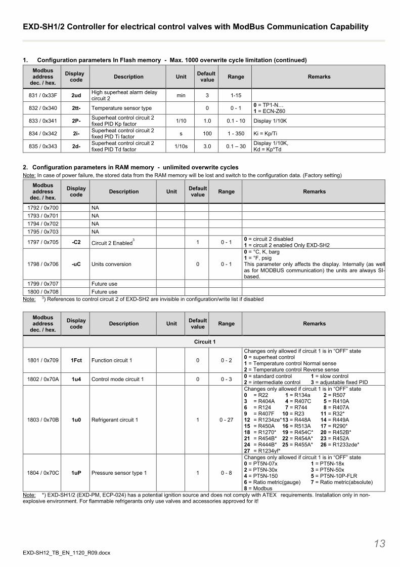
1. Configuration parameters In Flash memory - Max. 1000 overwrite cycle limitation (continued) Modbus address
dec. / hex. Display
code Description Unit Default value Range Remarks
831 / 0x33F 2ud High superheat alarm delay circuit 2 min 3 1-15
832 / 0x340 2tt- Temperature sensor type 0 0 - 1 0 = TP1-N… 1 = ECN-Z60
833 / 0x341 2P- Superheat control circuit 2 fixed PID Kp factor 1/10 1.0 0.1 - 10 Display 1/10K
834 / 0x342 2i- Superheat control circuit 2 fixed PID Ti factor s 100 1 - 350 Ki = Kp/Ti
835 / 0x343 2d- Superheat control circuit 2 fixed PID Td factor 1/10s 3.0 0.1 – 30 Display 1/10K,
Kd = Kp*Td
2. Configuration parameters in RAM memory - unlimited overwrite cycles Note: In case of power failure, the stored data from the RAM memory will be lost and switch to the configuration data. (Factory setting)
Modbus address
dec. / hex. Display
code Description Unit Default value Range Remarks
1792 / 0x700 NA 1793 / 0x701 NA 1794 / 0x702 NA 1795 / 0x703 NA
1797 / 0x705 -C2 Circuit 2 Enabled3 1 0 - 1 0 = circuit 2 disabled
1 = circuit 2 enabled Only EXD-SH2
1798 / 0x706 -uC Units conversion 0 0 - 1
0 = °C, K, barg 1 = °F, psig This parameter only affects the display. Internally (as well as for MODBUS communication) the units are always SI-based.
1799 / 0x707 Future use 1800 / 0x708 Future use
Note: 3) References to control circuit 2 of EXD-SH2 are invisible in configuration/write list if disabled
Modbus address
dec. / hex. Display
code Description Unit Default value Range Remarks
Circuit 1
1801 / 0x709 1Fct Function circuit 1 0 0 - 2
Changes only allowed if circuit 1 is in “OFF” state 0 = superheat control 1 = Temperature control Normal sense 2 = Temperature control Reverse sense
1802 / 0x70A 1u4 Control mode circuit 1 0 0 - 3 0 = standard control 1 = slow control 2 = intermediate control 3 = adjustable fixed PID
1803 / 0x70B 1u0 Refrigerant circuit 1 1 0 - 27
Changes only allowed if circuit 1 is in “OFF” state 0 = R22 1 = R134a 2 = R507 3 = R404A 4 = R407C 5 = R410A 6 = R124 7 = R744 8 = R407A 9 = R407F 10 = R23 11 = R32* 12 = R1234ze* 13 = R448A 14 = R449A 15 = R450A 16 = R513A 17 = R290* 18 = R1270* 19 = R454C* 20 = R452B* 21 = R454B* 22 = R454A* 23 = R452A 24 = R444B* 25 = R455A * 26 = R1233zde* 27 = R1234yf*
1804 / 0x70C 1uP Pressure sensor type 1 1 0 - 8
Changes only allowed if circuit 1 is in “OFF” state 0 = PT5N-07x 1 = PT5N-18x 2 = PT5N-30x 3 = PT5N-50x 4 = PT5N-150 5 = PT5N-10P-FLR 6 = Ratio metric(gauge) 7 = Ratio metric(absolute) 8 = Modbus
Note: *) EXD-SH1/2 (EXD-PM, ECP-024) has a potential ignition source and does not comply with ATEX requirements. Installation only in non-explosive environment. For flammable refrigerants only use valves and accessories approved for it!
EXD-SH1/2 Controller for electrical control valves with ModBus Communication Capability
14 EXD-SH12_TB_EN_1120_R09.docx
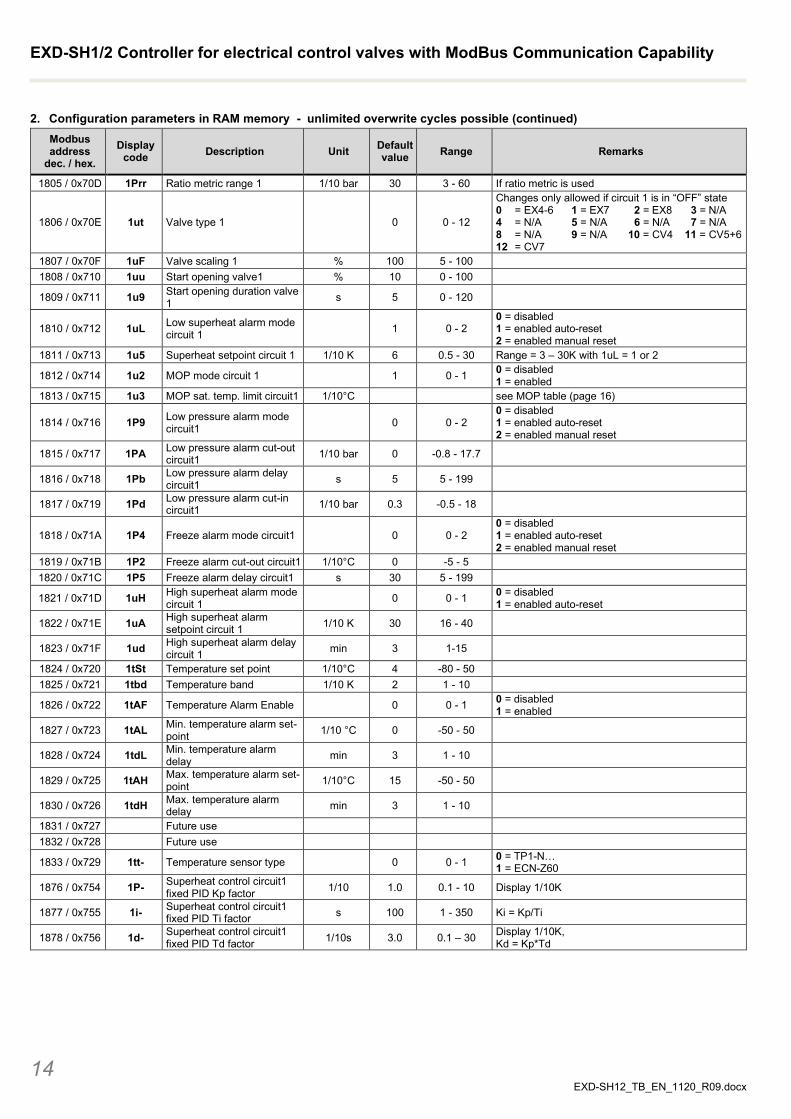
2. Configuration parameters in RAM memory - unlimited overwrite cycles possible (continued) Modbus address
dec. / hex. Display
code Description Unit Default value Range Remarks
1805 / 0x70D 1Prr Ratio metric range 1 1/10 bar 30 3 - 60 If ratio metric is used
1806 / 0x70E 1ut Valve type 1 0 0 - 12
Changes only allowed if circuit 1 is in “OFF” state 0 = EX4-6 1 = EX7 2 = EX8 3 = N/A 4 = N/A 5 = N/A 6 = N/A 7 = N/A 8 = N/A 9 = N/A 10 = CV4 11 = CV5+6 12 = CV7
1807 / 0x70F 1uF Valve scaling 1 % 100 5 - 100 1808 / 0x710 1uu Start opening valve1 % 10 0 - 100
1809 / 0x711 1u9 Start opening duration valve 1 s 5 0 - 120
1810 / 0x712 1uL Low superheat alarm mode circuit 1 1 0 - 2
0 = disabled 1 = enabled auto-reset 2 = enabled manual reset
1811 / 0x713 1u5 Superheat setpoint circuit 1 1/10 K 6 0.5 - 30 Range = 3 – 30K with 1uL = 1 or 2
1812 / 0x714 1u2 MOP mode circuit 1 1 0 - 1 0 = disabled 1 = enabled
1813 / 0x715 1u3 MOP sat. temp. limit circuit1 1/10°C see MOP table (page 16)
1814 / 0x716 1P9 Low pressure alarm mode circuit1 0 0 - 2
0 = disabled 1 = enabled auto-reset 2 = enabled manual reset
1815 / 0x717 1PA Low pressure alarm cut-out circuit1 1/10 bar 0 -0.8 - 17.7
1816 / 0x718 1Pb Low pressure alarm delay circuit1 s 5 5 - 199
1817 / 0x719 1Pd Low pressure alarm cut-in circuit1 1/10 bar 0.3 -0.5 - 18
1818 / 0x71A 1P4 Freeze alarm mode circuit1 0 0 - 2 0 = disabled 1 = enabled auto-reset 2 = enabled manual reset
1819 / 0x71B 1P2 Freeze alarm cut-out circuit1 1/10°C 0 -5 - 5 1820 / 0x71C 1P5 Freeze alarm delay circuit1 s 30 5 - 199
1821 / 0x71D 1uH High superheat alarm mode circuit 1 0 0 - 1 0 = disabled
1 = enabled auto-reset
1822 / 0x71E 1uA High superheat alarm setpoint circuit 1 1/10 K 30 16 - 40
1823 / 0x71F 1ud High superheat alarm delay circuit 1 min 3 1-15
1824 / 0x720 1tSt Temperature set point 1/10°C 4 -80 - 50 1825 / 0x721 1tbd Temperature band 1/10 K 2 1 - 10
1826 / 0x722 1tAF Temperature Alarm Enable 0 0 - 1 0 = disabled 1 = enabled
1827 / 0x723 1tAL Min. temperature alarm set-point 1/10 °C 0 -50 - 50
1828 / 0x724 1tdL Min. temperature alarm delay min 3 1 - 10
1829 / 0x725 1tAH Max. temperature alarm set- point 1/10°C 15 -50 - 50
1830 / 0x726 1tdH Max. temperature alarm delay min 3 1 - 10
1831 / 0x727 Future use 1832 / 0x728 Future use
1833 / 0x729 1tt- Temperature sensor type 0 0 - 1 0 = TP1-N… 1 = ECN-Z60
1876 / 0x754 1P- Superheat control circuit1 fixed PID Kp factor 1/10 1.0 0.1 - 10 Display 1/10K
1877 / 0x755 1i- Superheat control circuit1 fixed PID Ti factor s 100 1 - 350 Ki = Kp/Ti
1878 / 0x756 1d- Superheat control circuit1 fixed PID Td factor 1/10s 3.0 0.1 – 30 Display 1/10K,
Kd = Kp*Td
EXD-SH1/2 Controller for electrical control valves with ModBus Communication Capability
15 EXD-SH12_TB_EN_1120_R09.docx
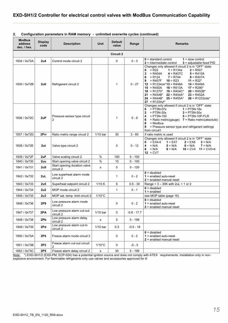
2. Configuration parameters in RAM memory - unlimited overwrite cycles (continued) Modbus address
dec. / hex. Display
code Description Unit Default value Range Remarks
Circuit 2
1834 / 0x72A 2u4 Control mode circuit 2 0 0 - 3 0 = standard control 1 = slow control 2 = intermediate control 3 = adjustable fixed PID
1835 / 0x72B 2u0 Refrigerant circuit 2 1 0 - 27
Changes only allowed if circuit 2 is in “OFF” state 0 = R22 1 = R134a 2 = R507 3 = R404A 4 = R407C 5 = R410A 6 = R124 7 = R744 8 = R407A 9 = R407F 10 = R23 11 = R32* 12 = R1234ze* 13 = R448A 14 = R449A 15 = R450A 16 = R513A 17 = R290* 18 = R1270* 19 = R454C* 20 = R452B* 21 = R454B* 22 = R454A* 23 = R452A 24 = R444B* 25 = R455A * 26 = R1233zde* 27 = R1234yf*
1836 / 0x72C 2uP Pressure sensor type circuit 2 1 0 - 9
Changes only allowed if circuit 2 is in “OFF” state 0 = PT5N-07x 1 = PT5N-18x 2 = PT5N-30x 3 = PT5N-50x 4 = PT5N-150 5 = PT5N-10P-FLR 6 = Ratio metric(gauge) 7 = Ratio metric(absolute) 8 = Modbus 9 = Pressure sensor type and refrigerant settings from circuit1
1837 / 0x72D 2Prr Ratio metric range circuit 2 1/10 bar 30 3 - 60 If ratio metric is used
1838 / 0x72E 2ut Valve type circuit 2 0 0 - 12
Changes only allowed if circuit 2 is in “OFF” state 0 = EX4-6 1 = EX7 2 = EX8 3 = N/A 4 = N/A 5 = N/A 6 = N/A 7 = N/A 8 = N/A 9 = N/A 10 = CV4 11 = CV5+6 12 = CV7
1839 / 0x72F 2uF Valve scaling circuit 2 % 100 5 - 100 1840 / 0x730 2uu Start opening valve circuit 2 % 10 0 - 100
1841 / 0x731 2u9 Start opening duration valve circuit 2 s 5 0 - 120
1842 / 0x732 2uL Low superheat alarm mode circuit 2 1 0 - 2
0 = disabled 1 = enabled auto-reset 2 = enabled manual reset
1843 / 0x733 2u5 Superheat setpoint circuit 2 1/10 K 6 0.5 - 30 Range = 3 – 30K with 2uL = 1 or 2
1844 / 0x734 2u2 MOP mode circuit 2 1 0 - 1 0 = disabled 1 = enabled
1845 / 0x735 2u3 MOP sat. temp. limit circuit 2 1/10°C see MOP table (page 16)
1846 / 0x736 2P9 Low pressure alarm mode circuit 2 0 0 - 2
0 = disabled 1 = enabled auto-reset 2 = enabled manual reset
1847 / 0x737 2PA Low pressure alarm cut-out circuit 2 1/10 bar 0 -0.8 - 17.7
1848 / 0x738 2Pb Low pressure alarm delay circuit 2 s 5 5 - 199
1849 / 0x739 2Pd Low pressure alarm cut-in circuit 2 1/10 bar 0.3 -0.5 - 18
1850 / 0x73A 2P4 Freeze alarm mode circuit 2 0 0 - 2 0 = disabled 1 = enabled auto-reset 2 = enabled manual reset
1851 / 0x73B 2P2 Freeze alarm cut-out circuit 2 1/10°C 0 -5 - 5
1852 / 0x73C 2P5 Freeze alarm delay circuit 2 s 30 5 - 199 Note: *) EXD-SH1/2 (EXD-PM, ECP-024) has a potential ignition source and does not comply with ATEX requirements. Installation only in non-explosive environment. For flammable refrigerants only use valves and accessories approved for it!
EXD-SH1/2 Controller for electrical control valves with ModBus Communication Capability
EXD-SH12_TB_EN_1120_R09.docx Emerson Climate Technologies GmbH shall not be liable for errors in the stated capacities, dimensions, etc., as well as typographic errors. Products, specifications, designs and technical data contained in this document are subject to modification by us without prior notice. Illustrations are not binding. The Emerson Climate Technologies logo is a trademark and service mark of Emerson Electric Co. Emerson Climate Technologies Inc. is a subsidiary of Emerson Electric Co.
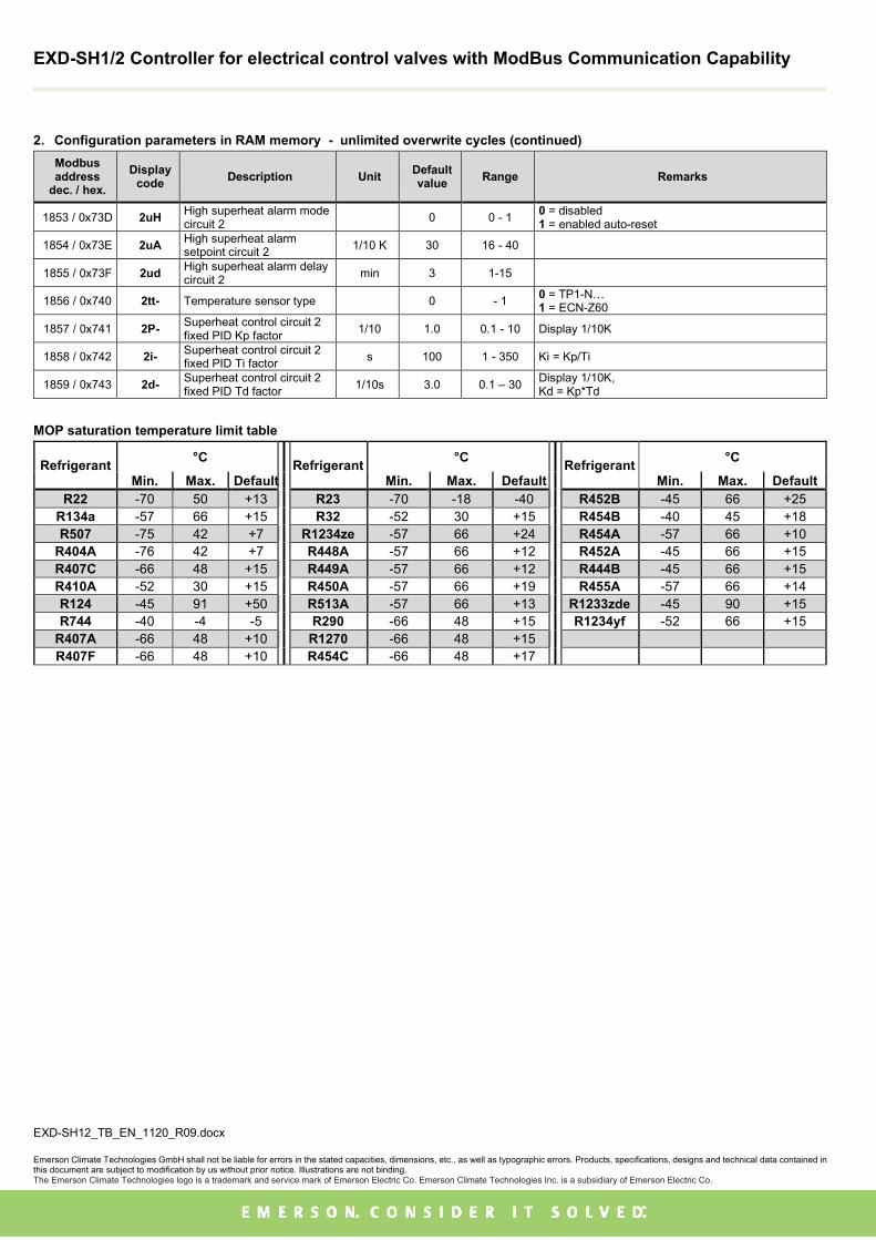
2. Configuration parameters in RAM memory - unlimited overwrite cycles (continued) Modbus address
dec. / hex. Display
code Description Unit Default value Range Remarks
1853 / 0x73D 2uH High superheat alarm mode circuit 2 0 0 - 1 0 = disabled
1 = enabled auto-reset
1854 / 0x73E 2uA High superheat alarm setpoint circuit 2 1/10 K 30 16 - 40
1855 / 0x73F 2ud High superheat alarm delay circuit 2 min 3 1-15
1856 / 0x740 2tt- Temperature sensor type 0 - 1 0 = TP1-N… 1 = ECN-Z60
1857 / 0x741 2P- Superheat control circuit 2 fixed PID Kp factor 1/10 1.0 0.1 - 10 Display 1/10K
1858 / 0x742 2i- Superheat control circuit 2 fixed PID Ti factor s 100 1 - 350 Ki = Kp/Ti
1859 / 0x743 2d- Superheat control circuit 2 fixed PID Td factor 1/10s 3.0 0.1 – 30 Display 1/10K,
Kd = Kp*Td
MOP saturation temperature limit table
Refrigerant °C Refrigerant °C Refrigerant °C Min. Max. Default Min. Max. Default Min. Max. Default
R22 -70 50 +13 R23 -70 -18 -40 R452B -45 66 +25 R134a -57 66 +15 R32 -52 30 +15 R454B -40 45 +18 R507 -75 42 +7 R1234ze -57 66 +24 R454A -57 66 +10
R404A -76 42 +7 R448A -57 66 +12 R452A -45 66 +15 R407C -66 48 +15 R449A -57 66 +12 R444B -45 66 +15 R410A -52 30 +15 R450A -57 66 +19 R455A -57 66 +14 R124 -45 91 +50 R513A -57 66 +13 R1233zde -45 90 +15 R744 -40 -4 -5 R290 -66 48 +15 R1234yf -52 66 +15
R407A -66 48 +10 R1270 -66 48 +15 R407F -66 48 +10 R454C -66 48 +17


![WHAT IS GOD - Routledge · Web viewDo the findings of scientists undermine the case for belief in God? [/SH1] [SH1] WHAT YOU WILL LEARN ABOUT IN THIS CHAPTER [/SH1] In this chapter](https://img.dokumen.tips/doc/110x75/5afbc25d7f8b9ad2209106f6/what-is-god-viewdo-the-findings-of-scientists-undermine-the-case-for-belief-in.jpg)