Embed Size (px)
Citation preview

TMExcellence in Motion
HARDWARE REFEREnCE
34 TM
42 TM
TM
www.imshome.com

The information in this book has been carefully checked and is believed to be accurate; however, no responsibility is assumed for inaccuracies.
Intelligent Motion Systems, Inc., reserves the right to make changes without further notice to any products herein to improve reliability, function or design. Intelligent Motion Systems, Inc., does not assume any liability arising out of the application or use of any product or circuit described herein; neither does it convey any license under its patent rights of others.
Intelligent Motion Systems and are trademarks of Intelligent Motion Systems, Inc.
Intelligent Motion Systems, Inc.’s general policy does not recommend the use of its products in life support or aircraft applications wherein a failure or malfunction of the product may directly threaten life or injury. Per Intelligent Motion Systems, Inc.’s terms and conditions of sales, the user of Intelligent Motion Systems, Inc., products in life support or aircraft
applications assumes all risks of such use and indemnifies Intelligent Motion Systems, Inc., against all damages.
TM
MDriveAC Plus2 Motion Control Software ReferenceRevision R052506
Copyright © 2006 ntelligent Motion Systems, Inc.All Rights Reserved
MDrivePlus Motion Control Hardware Reference Change Log
Date Revision Changes
03/07/2006 R030706 Initial Release
03/31/2006 R033106 Added CANopen Hardware Sections, 1.5, 1.6. Changed page numbering scheme.
05/05/2006 R050406 Removed Ambient Temperature Specification, Added Cordset information to Appendix E.
05/25/2006 R052506 Replaced MD-CC401-000 USB to RS-422 driver installation instructions with instructions relevant to Windows XP Service Pack 2 in Appendix E, pages A-28 and A-29.

i
Table Of Contents
Getting Started - MDriveAC Plus2 Motion Control ....................................................................1-1Before You Begin....................................................................................................................... 1-1Tools and Equipment Required................................................................................................. 1-1Connecting Power..................................................................................................................... 1-1Install IMS USB Communications Cable (Appendix E)............................................................ 1-1Connecting Communications ................................................................................................... 1-1Install IMS Terminal Software ................................................................................................... 1-1Establishing Communications................................................................................................... 1-2Testing the MDriveAC Plus2 Motion Control .......................................................................... 1-3Make the MDriveAC Plus2 Motion Control Move ................................................................... 1-3Apply Power to the MDriveAC Plus2 Motion Control.............................................................. 1-3Motion Control Example Using Program Mode........................................................................ 1-4Programming Notes .................................................................................................................. 1-4
Part 1: Hardware Specifications
Section 1.1: MDrive34AC Plus2 Motion Control Product Introduction......................................1-6Introduction to the MDrive34AC Plus2 Motion Control System.............................................. 1-6Standard Feature Summary ....................................................................................................... 1-7
Section 1.2: MDrive34AC Plus2 Detailed Specifications .........................................................1-8Standard Electrical Specifications .............................................................................................. 1-8Thermal Specifications .............................................................................................................. 1-8Sealing Specifications (-65 Sealed Versions Only) ...................................................................... 1-8Standard Motion Specifications................................................................................................. 1-8Software Specifications .............................................................................................................. 1-9Motor Specifications ................................................................................................................. 1-9Mechanical SpecificationsDimensions in Inches (mm) ............................................................ 1-10Pin/Wire Assignments ............................................................................................................. 1-10Options and Accessories .......................................................................................................... 1-11
Section 1.3: MDrive42AC Plus2 Motion Control Product Introduction...................................1-12Introduction to the MDrive42AC Plus2 Motion Control System............................................ 1-12Standard Feature Summary ..................................................................................................... 1-13
Section 1.4: MDrive42AC Plus2 Detailed Specifications .......................................................1-14Standard Electrical Specifications ............................................................................................ 1-14Thermal Specifications ............................................................................................................ 1-14Sealing Specifications (-65 Sealed Versions Only) .................................................................... 1-14Standard Motion Specifications............................................................................................... 1-14Software Specifications ............................................................................................................ 1-15Motor Specifications ............................................................................................................... 1-15Mechanical SpecificationsDimensions in Inches (mm) ............................................................ 1-16Pin/Wire Assignments ............................................................................................................. 1-16Options and Accessories .......................................................................................................... 1-16
Section 1.5: MDrive34AC Plus2 CANopen Detailed Specifications .......................................1-18Standard Electrical Specifications ............................................................................................ 1-18Thermal Specifications ............................................................................................................ 1-18Sealing Specifications (-65 Sealed Versions Only) .................................................................... 1-18Motor Specifications ............................................................................................................... 1-19Mechanical SpecificationsDimensions in Inches (mm) ............................................................ 1-19Pin/Wire Assignments ............................................................................................................. 1-20
Section 1.6: MDrive42AC Plus2 CANopen Detailed Specifications .......................................1-21Standard Electrical Specifications ............................................................................................ 1-21Thermal Specifications ............................................................................................................ 1-21Sealing Specifications (-65 Sealed Versions Only) .................................................................... 1-21Motor Specifications ............................................................................................................... 1-22Mechanical SpecificationsDimensions in Inches (mm) ............................................................ 1-22
ii iii
Pin/Wire Assignments ............................................................................................................. 1-23
Part 2: Connecting and Interfacing
Section 2.1: Interfacing MDriveAC Plus2 Communications .......................................................2-2Available Communications Cables/Converters .......................................................................... 2-2Interfacing Single Mode Communications ................................................................................ 2-2
Single Mode Communications Full Duplex (RS-422) ......................................................... 2-2Single Mode Communications Half Duplex (RS-485) ........................................................ 2-3
Interfacing Party Mode Communications.................................................................................. 2-3Data Cable Termination Resistors...................................................................................... 2-4
MDriveAC Plus2 Motion Control Communication Format ..................................................... 2-4MDriveAC Plus2 Motion Control (MDI) Response to Echo Mode .......................................... 2-4Using Check Sum ..................................................................................................................... 2-6MDriveAC Plus2 Motion Control Party Mode Sample Codes .................................................. 2-7MDriveAC Plus2 Motion Control Immediate Party Mode Sample Codes................................. 2-8
Section 2.2: Interfacing and Using the MDriveAC Plus2 Motion Control I/O.............................2-9The MDriveAC Plus2 Motion Control Digital I/O .................................................................. 2-9
8 I/O Configuration ......................................................................................................... 2-9Uses of the Digital I/O.............................................................................................................. 2-9MDriveAC Plus2 Motion Control Digital Input Functions .................................................... 2-10
Programmable Input Functions ....................................................................................... 2-10Dedicated Input Functions .............................................................................................. 2-10Active States Defined ...................................................................................................... 2-10
MDriveAC Plus2 Motion Control Digital Output Functions ................................................. 2-11Programmable Output Functions..................................................................................... 2-11Dedicated Output Functions ........................................................................................... 2-11
MDriveAC Plus2 Motion Control I/O Ratings....................................................................... 2-12MDriveAC Plus2 Motion Control I/O Connection Map........................................................ 2-12General Purpose I/O Usage Examples — Enhanced I/O Set ................................................... 2-13
Input Interface Example - Switch Input Example (Sinking Input) ..................................... 2-13Input Interface Example - Switch Input Example (Sourcing Input) .................................... 2-14Output Interface Example (Sinking Output) .................................................................... 2-15Output Interface Example (Sourcing Output)................................................................... 2-16
Dedicated Digital I/O - Enhanced I/O Set.............................................................................. 2-17Step/Direction/Clock I/O ....................................................................................................... 2-17Capture/Trip ........................................................................................................................... 2-17Interfacing the Analog Input ................................................................................................... 2-18
Sample Usage ................................................................................................................. 2-18
Appendices
Appendix A: MDriveAC Plus2 Motion Control Motor Performance........................................... A-3MDrive34AC Plus2 Motion Control ........................................................................................A-3
Speed-Torque Curves ........................................................................................................A-3Motor Specifications .................................................................................................................A-3MDrive42AC Plus2 Motion Control ........................................................................................A-4
Speed-Torque Curves ........................................................................................................A-4Motor Specifications .................................................................................................................A-5
Appendix B: MDrive with Planetary Gearbox ........................................................................... A-6Section Overview ......................................................................................................................A-6Product Overview .....................................................................................................................A-6Selecting a Planetary Gearbox ...................................................................................................A-7
Calculating the Shock Load Output Torque (TAB) .............................................................A-7System Inertia .........................................................................................................................A-10Planetary Gearbox Inertia........................................................................................................A-14MDrive34AC Plus2 with Planetary Gearbox...........................................................................A-15Installing a Driving Device on a Planetary Gearbox.................................................................A-16
Appendix C: I/O Application Guide ......................................................................................... A-17Standard I/O Set Interfacing and Application..........................................................................A-17
NPN Sinking Input........................................................................................................A-17PNP Sourcing Input .......................................................................................................A-18

ii iii
Mixed Input/Output Example .........................................................................................A-19Sinking Output ..............................................................................................................A-19
Enhanced I/O Set Interfacing and Application........................................................................A-20NPN Sinking Input........................................................................................................A-20PNP Sourcing Input .......................................................................................................A-20Sourcing Output.............................................................................................................A-21Mixed Input/Output Example .........................................................................................A-22
Interfacing Inputs as a Group Example ...................................................................................A-22Interfacing Outputs as a Group Example ................................................................................A-23
Appendix D: MDriveAC Plus Motion Control Closed Loop Control......................................... A-24MDrive Motion Control Closed Loop Options.......................................................................A-24
Internal Encoder.............................................................................................................A-24Remote Encoder..............................................................................................................A-25
Appendix E: Optional Cables and Cordsets .............................................................................. A-26Communications Converter Cable USB to 5-Pin M12 (MD-CC401-000) ............................A-26Installation Procedure for the MX-CC400-000 .......................................................................A-27
Installing the Cable/VCP Drivers ....................................................................................A-27Determining the Virtual COM Port (VCP) .....................................................................A-29
Cordsets .................................................................................................................................A-29
List Of FiguresFigure GS.1: MDrive CD Screens ............................................................................................. 1-1Figure GS.2: IMS Terminal Main Screen................................................................................... 1-2Figure GS.3: IMS Terminal Preferences ..................................................................................... 1-2Figure GS.4: IMS Terminal Sign-On Message ........................................................................... 1-3Figure GS.5: Downloading the Program.................................................................................... 1-4
Part 1: Hardware Specifications
Figure 1.1.1: MDrive34AC Plus2 Motion Control.................................................................... 1-6Figure 1.2.1: MDrive34AC Plus2 Motion Control Mechanical Specifications......................... 1-10Figure 1.2.2: P1 19-Pin M23 (male) - 8 I/O Configuration .................................................... 1-10Figure 1.2.3: P1 19-Pin M23 (male) - Optional Remote Encoder Configuration .................... 1-10Figure 1.2.4: P2 5-Pin M12 (female) RS-422/485 Communications Connector ..................... 1-10Figure 1.2.5: P3 3-Pin Euro AC Connector............................................................................. 1-10Figure 1.3.1: MDrive42AC Plus2 Motion Control.................................................................. 1-12Figure 1.4.1: MDrive42AC Plus2 Motion Control Mechanical Specifications......................... 1-16Figure 1.4.2: P1 19-Pin M23 (male) - Enhanced I/O Configuration....................................... 1-16Figure 1.4.3: P1 19-Pin M23 (male) - Optional Remote Encoder Configuration .................... 1-16Figure 1.4.4: P2 5-Pin M12 (Female) RS-422/485 Communications Connector .................... 1-16Figure 1.4.5: P3 3-Pin Euro AC Connector............................................................................. 1-16Figure 1.5.1: MDrive34AC Plus2 Motion Control Mechanical Specifications......................... 1-19Figure 1.5.2: P1 19-Pin M23 (male) - 8 I/O Configuration .................................................... 1-20Figure 1.5.3: P1 19-Pin M23 (male) - Optional Remote Encoder Configuration .................... 1-20Figure 1.5.4: P2 5-Pin M12 (Male) CANopen Communications Connector .......................... 1-20Figure 1.5.5: P3 3-Pin Euro AC Connector............................................................................. 1-20Figure 1.6.1: MDrive42AC Plus2 Motion Control Mechanical Specifications......................... 1-22Figure 1.6.2: P1 19-Pin M23 (male) - 8 I/O Configuration .................................................... 1-23Figure 1.6.3: P1 19-Pin M23 (male) - Optional Remote Encoder Configuration .................... 1-23Figure 1.6.4: P2 5-Pin M12 (Male) CANopen Communications Connector .......................... 1-23Figure 1.6.5: P3 3-Pin Euro AC Connector............................................................................. 1-23
Part 2: Connecting and Interfacing
Figure 2.1.1: Full Duplex Communications (RS-422)............................................................... 2-2Figure 2.1.2: Half Duplex 2 Wire Communications (RS-485) .................................................. 2-3Figure 2.1.3: RS-485 Interface, Multiple MDriveAC Plus2Motion Control System.................. 2-4Figure 2.2.1: Uses for the Digital I/O........................................................................................ 2-9Figure 2.2.2: I/O Connection Map ......................................................................................... 2-12Figure 2.2.3: Switch Interface to Input, Sinking ...................................................................... 2-13Figure 2.2.4 Sourcing Input Example using a Push Button Switch .......................................... 2-14Figure 2.2.5: Sinking Output Example.................................................................................... 2-15Figure 2.2.6: Sourcing Output Example .................................................................................. 2-16Figure 2.2.7: MDriveAC Plus2 Motion Control Clock Functions ........................................... 2-17Figure 2.2.8: Analog Input - Voltage Mode ............................................................................. 2-18Figure 2.2.9: Analog Input - Current Mode ............................................................................ 2-19

iv
Appendices
Figure A.1: MDrive34AC Plus2 120VAC Motion Control Speed-Torque Curves .....................A-3Figure A.2: MDrive34AC Plus2 240VAC Motion Control Speed-Torque Curves .....................A-3Figure A.3: MDrive42AC Plus2 120VAC Motion Control Speed-Torque Curves .....................A-4Figure A.4: MDrive42AC Plus2 240VAC Motion Control Speed-Torque Curves .....................A-4Figure B.1: MDrive23 Torque-Speed Curve ..............................................................................A-8Figure B.2: Lead Screw System Inertia Considerations ............................................................A-10Figure B.3: Rack and Pinion System Inertia Considerations ....................................................A-11Figure B.4: Conveyor System Inertia Considerations...............................................................A-11Figure B.5: Rotary Table System Inertia Considerations ..........................................................A-12Figure B.6: Chain Drive System Inertia Considerations...........................................................A-13Figure B.7: Planetary Gearbox Specifications for MDrive34AC Plus2 .....................................A-15Figure C.1: NPN Interface to an MDI Sinking Input .............................................................A-17Figure C.2: PNP Interface to a Sourcing Input........................................................................A-18Figure C.3: Sinking Output to Relay.......................................................................................A-19Figure C.4: Mixed Output Example; Standard I/O Set............................................................A-19Figure C.5: NPN Sinking Input on an MDriveAC Plus2 Motion Control .............................A-20Figure C.6: PNP Sourcing Input on an MDriveAC Plus2 Motion Control .............................A-20Figure C.7: Sourcing Output to Sourcing Input ......................................................................A-21Figure C.8: Mixed Input/Output Example - Enhanced I/O ....................................................A-22Figure C.9: TTL Interface to an Input Group .........................................................................A-22Figure C.10: Outputs Interfaced to LED’s as a Group.............................................................A-23Figure D.1: Connecting a Remote Encoder.............................................................................A-25Figure E.1: MD-CC401-000...................................................................................................A-26Figure E.2: MD-CC401-000 Mechanical Specifications..........................................................A-26Figure E.3: Typical Communications Interface........................................................................A-27Figure E.4: Hardware Update Wizard......................................................................................A-27Figure E.5: Hardware Update Wizard Screen 2 .......................................................................A-28Figure E.6: Hardware Update Wizard Screen 3 .......................................................................A-28Figure E.7: Windows Logo Compatibility Testing ...................................................................A-28Figure E.8: Hardware Update Wizard Finish Installation.........................................................A-28Figure E.9: Hardware Properties..............................................................................................A-29Figure E.10: Windows Device Manager ..................................................................................A-29Figure E.11: MD-CS10x-000..................................................................................................A-29Figure E.12: MD-CS20x-000..................................................................................................A-30
List of Tables
Part 1: Hardware Specifications
Table 1.2.1: Connector P1 Pin Configuration ......................................................................... 1-11Table 1.2.2: P2 - RS-422/485 ................................................................................................. 1-11Table 1.2.3: P3 - AC Power ..................................................................................................... 1-11Table 1.4.1: Connector P1 Pin Configuration ......................................................................... 1-17Table 1.4.2: P2 - RS-422/485 ................................................................................................. 1-17Table 1.4.3: P3 - AC Power ..................................................................................................... 1-17Table 1.5.1: Connector P1 Pin Configuration ......................................................................... 1-20Table 1.5.2: P2 - CANopen .................................................................................................... 1-20Table 1.5.3: P3 - AC Power ..................................................................................................... 1-20Table 1.6.1: Connector P1 Pin Configuration ......................................................................... 1-23Table 1.6.2: P2 - CANopen .................................................................................................... 1-23Table 1.6.3: P3 - AC Power ..................................................................................................... 1-23
Part 2: Connecting and Interfacing
Table 2.1.1: MDI Response to Echo Mode - Party and Check Sum are Zero (0) ....................... 2-5Table 2.1.2: MDI Response to Echo Mode - Party is One (1) and Check Sum is Zero (0) ....... 2-5Table 2.1.3: MDI Response to Echo Mode - Party is Zero (0) and Check Sum is One (1) ....... 2-5Table 2.1.4: MDI Response to Echo Mode - Party and Check Sum are One (1) ....................... 2-6Table 2.2.1: Programmable Input Functions ........................................................................... 2-10Table 2.2.2: Dedicated Input Functions .................................................................................. 2-10Table 2.2.3: Programmable Output Functions ........................................................................ 2-11Table 2.2.4: Dedicated Output Functions ............................................................................... 2-11Table 2.2.5: MDriveAC Plus2 Motion Control I/O and Protection Ratings............................ 2-12
Appendices
Table B.1: Planetary Gearbox Operating Factor.........................................................................A-9Table B.2: Planetary Gearbox Inertia Moments .......................................................................A-14Table C.1: Output Bit Weight Examples - Outputs set as a group ...........................................A-23Table E.1: MD-CC401-000 Electrical Specifications...............................................................A-26Table E.2: MD-CS10x-000 Wire Color Chart ........................................................................A-28Table E.3: Euro AC Wire Color Chart ....................................................................................A-29

1-1Part 1: Hardware Specications
Getting Started Getting Started - MDriveAC Plus2 Motion Control
Before You Begin
The Quick Start guide is designed to help get you connected and communicating with the MDriveAC Plus2
Motion Control. The following examples will help you get the motor turning for the first time and introduce you to Immediate and Program modes of operation.
Tools and Equipment Required
• MDriveAC Plus2 Motion Control Unit.• Communications MD-CC401-000 or equivalent (USB to RS-422).• MDriveAC Plus2 Product CD or Internet access to www.imshome.com.• MD-CS10x-000 Single-End cordset (or equivalent).• 120 VAC or 240 VAC, Power Cable with Euro AC Connector.• Basic Tools: Wire Cutters / Strippers / Screwdriver.• A PC with Windows 9x, Windows 2000, Windows XP Service Pack 2.• 10 MB hard drive space.• A free USB port.
Connecting Power
Connect 120 VAC or 240 VAC, depending on the input voltage of you MDriveAC Plus2 Motion Control to connector P3 3-pin Euro AC.
Install IMS USB Communications Cable (Appendix E)
See Appendix E for detailed installation instructions for the MD-CC401-000
Connecting Communications
Connect host PC’s USB port to the MDriveAC Plus2 Motion Control 5-pin M12 connector using the MD-CC401-000 or equivalent.
Install IMS Terminal Software
1. Insert the MDrive CD into the CD Drive of your PC. If not available, go to http://www.imshome.com/software_interfaces.html.2. The CD will autostart. 3. Click the Software Button in the top-right navigation Area.4. Click the IMS Terminal link appropriate to your operating system.5. Click SETUP in the Setup dialog box and follow the on-screen instructions.6. Once IMS Terminal is installed, the Communications Settings can be checked and/or set.
WARNING! Please ensure that you read the sections of the product manual
pertaining to the MDriveAC Plus2 model you purchased in their entirety prior to placing the unit into full operation.
Figure GS.1: MDrive CD Screens

1-2 MDriveAC Plus2 Motion Control Hardware - Revision R052506 1-3Part 1: Hardware Specications
Establishing Communications
1. Open IMS Terminal by clicking Start>Programs>IMS Terminal>IMS Term. The Program Edit Window (left) and Terminal Window (right) will be displayed.
2. On the Menu Bar click Edit / Preferences to open the Preferences dialog box.3. Click on the Comm Settings tab to open the Comm Settings page.
a. Set Scroll Back to desired range of text lines to be displayed. b. Under Device, verify that MDrive has been selected, and also verify the Comm Port being
used. Do not change any other settings. Click “OK”.
W A R N I N G : Do not connect or disconnect DC input to the
MDriveAC Plus with power applied! Disconnect the AC power side to power down the DC Supply.
For battery operated systems, conditioning measures should be taken to prevent device damage caused by in-rush current draws, transient arcs and high voltage spikes.
Figure GS.2: IMS Terminal Main Screen
Figure GS.3: IMS Terminal Preferences

1-2 MDriveAC Plus2 Motion Control Hardware - Revision R052506 1-3Part 1: Hardware Specications
Apply Power to the MDriveAC Plus2 Motion Control
1. Verify that all connections have been made, then apply power to the MDriveAC Plus2 Motion Control. Click on the Phone icon or the Disconnect status box to establish communications between IMS Terminal and the MDriveAC Plus2. The following sign-on message should appear in the Terminal Window:
“Copyright 2001-2006 by Intelligent Motion Systems, Inc.”
2. If you can see the sign-on message, then the MDriveAC Plus2 is properly powered-up and communicating.
a. If the sign-on message does not appear, try using a software reset. Hold down the “Ctrl” key and press “C”. If the sign-on message still does not appear, check all connections, as well as all hardware and software configurations, then start IMS Terminal again.
3. You are now connected and communicating to the MDriveAC Plus2 Motion Control. Note: There are indicators at the bottom of the Terminal Window that show whether you are
connected or disconnected, the current Baud Rate, and the type of device (MDrive) for which the IMS Terminal is configured. These three items may be changed directly from this screen by double clicking on each of them.
Testing the MDriveAC Plus2 Motion Control
1. Click in the Terminal Window, and type (followed by ENTER): PR VM2. The MDriveAC Plus2 Motion Control will return a value of 7680003. Type the following in the Terminal Window (followed by ENTER): VM=360000 PR VM4. The MDriveAC Plus2Motion Control will return a value of 3600005. Type FD and press ENTER. (FD = Factory Defaults)
“Copyright 2001-2006 by Intelligent Motion Systems, Inc.”
should appear in the Terminal Window within a few seconds.
Make the MDriveAC Plus2 Motion Control Move
1. Type MR 51200 into the Terminal Window and press ENTER. (MR = Move Relative) a. With the default settings, the MDrive Motion Control should move one revolution in
approximately 0.066 seconds, or at a velocity of 15 revolutions per second.2. Type SL 102400 and press ENTER. (SL = Slew) a. With the default settings, the MDriveAC Plus2 Motion Control should run constantly at a
speed of approximately 2 revolutions per second or 120 revolutions per minute.3. Type SL 0 and press ENTER. The MDriveAC Plus2 Motion Control should decelerate to a full
stop.
Note: Entering MDriveAC Plus commands directly into
the Terminal Window is called “Immediate Mode”.
The MDriveAC Plus Motion Control command set is not case sensitive except for command DN = < >
Warning: If you have installed the MDriveAC Plus to a load, be sure the load can safely be
moved before testing.
Tip: A small piece of tape on the motor shaft is a visual aid to help see the shaft turning.
Figure GS.4: IMS Terminal Sign-On Message

1-4 MDriveAC Plus2 Motion Control Hardware - Revision R052506 1-5Part 1: Hardware Specications
Motion Control Example Using Program Mode
1. Click on drop-down menu View > New Edit Window to open the Program Edit Window.2. Type “GettingStarted.mxt” into the “Open a New file for editing” dialog box, and click “OK”.3. Click anywhere within the Program Edit Window, and type (followed by ENTER):
VA LP=0 ‘user variable name LP = start count 0A=100000 ‘set acceleration to 100000 steps/sec2
D=100000 ‘set deceleration to 100000 steps/sec2
PG 1 ‘enter program mode, start program at address 1LB AA ‘label program AAMR 250000 ‘move motor 250000 steps in the positive directionH ‘hold program execution until motion completesH 1000 ‘hold 1000 millisecondsMR –250000 ‘move motor 250000 steps in the negative directionH ‘hold program execution until motion completesH 1000 ‘hold 1000 millisecondsIC LP ‘increment user variable LPPR ” LP=”,LP; ‘print axis position, 4 characters used, the ‘terminal will display LP=1 LP=2 LP=3BR AA, LP<3 ‘branch to process label AA, if user variable LP< 3E ‘end program executionPG ‘exit program, return to immediate mode
4. Type FD in the Terminal Window and press ENTER to clear the MDrive buffer to factory defaults before downloading any program.
5. Click on drop-down menu Transfer > Download, or the “Down Arrow” on the menu bar, to transfer the program from the Program Edit Window to the Terminal Window. (Under “Source Type” choose “Edit Window”.)
6. Type EX 1 in the Terminal Window and press ENTER to execute the program. (EX = Execute at address 1.)
7. The MDriveAC Plus2 Motion Control will turn 250,000 microsteps in a clockwise direction, accelerating at 100,000 microsteps per sec2, then decelerating at 100,000 microsteps per sec2, pausing for 1000 milliseconds, then reversing the sequence in a counterclockwise direction, repeating the motion cycle 3 times until the program ends.
Programming Notes
The example above demonstrates basic commands that verify that your MDriveAC Plus2 Motion Control is communicating with your PC. More complex commands and movement may require that your I/O and/or Analog Input be interfaced and configured. Refer to MDriveAC Plus2 Motion Control Software Reference for details.
For more information on MDriveAC Plus Motion Control Programming and Command Control Sets, refer to the Software Section of this manual.
NOTE: Entering MDriveAC Plus commands into the Program Edit Window,
to be edited and saved, is called “Program Mode”.
NOTE: The program can be stopped by
pressing the Escape Button or by pressing Ctrl+C.
Figure GS.5: Downloading the Program

1-4 MDriveAC Plus2 Motion Control Hardware - Revision R052506 1-5Part 1: Hardware Specications
TMExcellence in Motion
Section 1.1: MDrive34AC Plus2 Motion Control Product Introduction
Section 1.2: MDrive34AC Plus2 Motion Control Specifications
Section 1.3: MDrive42AC Plus2 Motion Control Product Introduction
Section 1.4: MDrive42AC Plus2 Motion Control Specifications
Part 1: Hardware Specifications
TM

1-6 MDriveAC Plus2 Motion Control Hardware - Revision R052506 1-7Part 1: Hardware Specications
Section 1.1 MDrive34AC Plus2 Motion Control Product Introduction
Introduction to the MDrive34AC Plus2 Motion Control System
The MDrive34AC Plus2 Motion Con-trol system offers designers a low cost, intelligent motion controller inte-grated with a NEMA 34 high torque brushless motor and microstepping drive operating at 120 or 240 VAC.
Unsurpassed smoothness and performance delivered by the MDrive34AC are achieved through IMS's advanced 2nd generation current control. By applying innovative tech-niques to control current flow through the motor, resonance is significantly dampened over the entire speed range and audible noise is reduced.
The MDrive34AC accepts a broad input voltage range from 95 to 264 VAC, deliver-ing enhanced performance and speed. Over-sized input capacitors are used to minimize power line surges, reducing problems that can occur with long runs and multiple drive systems. An extended operating range of –40° to +85°C provides long life, trouble free service in demanding environments.
The MDrive34AC Plus2 Motion Control system adds a versatile array of functions by combining a complete programmable motion controller with our compact and cost effective MDrive34AC Microstepping Drive, adding little cost and no increase in size. Standard offerings include up to 8 general purpose I/O lines (sourcing or sinking) that operate to +24 VDC, one 10 bit analog input, electronic gearing, high speed position capture input/trip output, microstep resolutions up to 51,200 steps per revolution, 0 to 5 MHz step clock rate, and a full featured easy-to-program instruction set.
The MDrive34AC Plus2 Motion Control system communicates over RS-422/485 which allows for point-to-point or multiple unit configurations utilizing one communication port. Addressing and hardware support multiple uniquely addressed units communicating over a single line.
The MDrive34AC Plus2 Motion Control is available with optional closed loop control. This increases func-tionality by adding stall detection, position maintenance and find index mark.
The closed loop configuration is added via a 512 line (2048 edge) optical encoder with index mark, internal to the MDrive34AC so there is no increase in length. Or, for an expanded choice of line counts and resolutions, closed loop control is available with an interface to a remotely mounted user-supplied external encoder.
In addition to encoder options, the MDrive34AC Plus2 Motion Control has the capability of electronic gearing by following a rotary or linear axis at an electronically controlled ratio, or an output clock can be generated fixed to the internal step clock.
A sealed version designed to meet IP65 specifications is also available. The sealed assembly allows the MDrive34AC to be used in environments where exposure to dust and liquids may occur.
Available rotary motor configurations include three motor lengths, an optional rear control knob for manual positioning and an integrated planetary gearbox. Interface connections are accomplished using standard indus-trial connectors.
Note: The MDriveAC Plus Motion Control is available in a CAN
communications configuration. For more information see the IMS Website.
Figure 1.1.1: MDrive34AC Plus2 Motion Control

1-6 MDriveAC Plus2 Motion Control Hardware - Revision R052506 1-7Part 1: Hardware Specications
Standard Feature Summary
n Highly Integrated Microstepping Driver/Motion Controller with Optional Encoder/NEMA 34 Brushless High Torque Motor
n Advanced 2nd Generation Current Control for Exceptional Performance and Smoothnessn Single Supply: 120 or 240 VACn Low Costn Extremely Compactn High Positioning Accuracyn No Tuning Requiredn Stable at Low Speedsn No Dithering at Zero Speedn High Starting Torquen Allows for Greater Inertia Mismatchn Built-in Regeneration Circuitryn Available Options:[ Integral Optical Encoder for Closed Loop Control
[ Remote Encoder (not supplied) for Closed Loop Control [ Control Knob for Manual Positioning [ Integrated Planetary Gearbox [ IP65 Sealed Configurationn Three Motor Lengths Availablen Auxiliary Logic Power Supply Inputn Up to 5 MHz Step Clock Raten 20 Microstep Resolutions up to
51,200 Steps Per Rev Including:Degrees, Metric, Arc Minutes
n Open or Optional Closed Loop Controln Programmable Motor Currentn Up to Eight +24 VDC Tolerant I/O Lines,
Sourcing or Sinkingn One 10 Bit Analog Input Selectable:
0 to +5 VDC, 0 to +10 VDC, 0-20 mA, 4-20 mAn RS-422/485 Communicationsn 62 Software Addresses for Multi-Drop Communicationsn High Speed Position Capture Input or Trip Outputn Electronic Gearing

1-8 MDriveAC Plus2 Motion Control Hardware - Revision R052506 1-9Part 1: Hardware Specications
WARNING! Because the MDriveAC Plus2 consists of three
core components, a power supply, a drive and a motor, close attention must be paid to the thermal environment where the device is used. See Thermal Specifications.
SECTION 1.2 MDrive34AC Plus2 Detailed Specifications
Standard Electrical Specifications
Input Voltage (+VAC)
120V MDrive ......................................................................................95 to 132 VAC @ 50/60 Hz240V MDrive ......................................................................................95 to 264 VAC @ 50/60 Hz
Aux. Logic Input Voltage
Range....................................................................................................................+12 to +24 VDC(Maintains power to control and feedback circuits [only] when input voltage is removed)
Analog Input (IN5)
Resolution..............................................................................................................................10 BitVoltage Range .............................................. 0 to +5 VDC, 0 to +10 VDC, 4 to 20mA, 0 to 20mA
General Purpose I/O
Number/TypeStandard............................................................................... 8 Sourcing or Sinking Inputs/OutputsRemote Encoder Option ............................. 4 Sourcing or Sinking Inputs/Outputs - 4Encoder I/OVoltage RangeInput................................................................................... TTL level compatible, up to +24 VDCOutput ................................................................................................... (Sinking) up to +24 VDC
Logic ThresholdLogic 0 .............................................................................................................................<0.8VDCLogic 1 .............................................................................................................................>2.2VDCOutput Sink Current (per channel)* .........................................................................Up to 600 mA Protection .......................................... Over Temp, Short Circuit (sinking), Transient Over Voltage, Inductive Clamp (sourcing)
Communication
Protocol (Standard) ....................................................RS-422/RS-485, Full/Half Duplex SelectableBaud Rate ............................................................................... 4.8k, 9.6k, 19.2k, 38.4k, 115.2kbps
* See I/O Ratings on In Section 2.3: Interfacing the MDriveAC Plus2 Motion Control I/O
Thermal Specifications
Motor Temperature ............................................................................................100°C (maximum)Heat Sink Temperature ........................................................................................85°C (maximum)Operating Temperature ..........................................................................................-40°C to +85°C
Sealing Specifications (-65 Sealed Versions Only)
IP Specification .......................................................................................................................IP-65
Standard Motion Specifications
Microstep Resolution – Open Loop ConfigurationNumber of Settings ..................................................................................................................... 20Steps per Revolution ......................... 200, 400, 800, 1000, 1600, 2000, 3200, 5000, 6400,10000, 12800, 20000, 25000, 25600, 40000, 50000, 51200, 36000 (0.01 deg/µstep), 21600 (1 arc minute/µstep), 25400 (0.001 mm/µstep)

1-8 MDriveAC Plus2 Motion Control Hardware - Revision R052506 1-9Part 1: Hardware Specications
Encoder (Optional)
Type ....................................................................................................Internal Differential, OpticalResolution............................................................................512 Lines/2048 counts per Revolution
Counters
Type .................................................................................................... Position (C1), Encoder (C2)Resolution..............................................................................................................................32 BitEdge Rate (Max) .................................................................................................................. 5 MHz
Velocity
Range................................................................................................. ±5,000,000 Steps per SecondResolution................................................................................................. 0.5961 Steps per Second
Acceleration/Deceleration
Range................................................................................................... 1.5 x 10⁹ Steps per Second2
Resolution....................................................................................................90.9 Steps per Second2
† Adjusting the microstep resolution can increase the range.
Software Specifications
Program Storage, Type/Size ...................................................................................Flash/6384 BytesUser Registers................................................................................................................... (4) 32 BitUser Program Labels and Variables ............................................................................................ 192Math, Logic and Conditional Functions ............ +, –, x,÷, >, <, =, <=, >=, AND, OR, XOR, NOTBranch Functions ...................................................... Branch & Call (conditonal or unconditional)Predefined I/O Functions...................................Inputs Home, Limit Plus, Limit Minus, Go, Stop, Pause, Jog Plus, Jog Minus, Analog InOutputs ................................................................................Moving, Fault, Stall, Velocity ChangeTrip Functions ....................................Trip on Input, Trip on Position, Trip on Time, Trip CaptureParty Mode Addresses ................................................................................................................. 62Encoder Functions ............................................Stall Detection, Position Maintenance, Find Index
Motor Specifications
Single Length
Holding Torque............................................................................................... 330 oz-in/233 N-cmDetent Torque................................................................................................. 10.9 oz-in/7.7 N-cmRotor Inertia ...................................................................................0.01416 oz-in-sec2/1.0 kg-cm2
Weight (Motor + Driver)............................................................................................. 3.8 lb/2.9 kg
Double Length
Holding Torque............................................................................................... 500 oz-in/353 N-cmDetent Torque............................................................................................. 14.16 oz-in/14.0 N-cmRotor Inertia ...................................................................................0.02266 oz-in-sec2/1.6 kg-cm2
Weight (Motor + Driver)............................................................................................. 5.2 lb/3.5 kg
Triple Length
Holding Torque............................................................................................... 750 oz-in/529 N-cmDetent Torque............................................................................................. 19.83 oz-in/10.0 N-cmRotor Inertia ...................................................................................0.04815 oz-in-sec2/3.4 kg-cm2
WARNING! When using the MDriveAC Plus2 Motion Control
with optional internal optical encoder, no axial force may be applied to the motor shaft without use of a load bearing isolation coupling.

1-10 MDriveAC Plus2 Motion Control Hardware - Revision R052506 1-11Part 1: Hardware Specications
Weight (Motor + Driver)............................................................................................. 8.6 lb/5.0 kg
Mechanical Specifications
Dimensions in Inches (mm)
LMAX
Ø 0.55 +0/-0.0005 (Ø 14.0 +0/-0.013)
0.08 ±0.004 (2.0 ±0.1)0.40
(10.1)
0.87 ±0.010(22 ±0.25)
1.46 ±0.039 (37.0 ±1.0)
LMAX2 2.70 (68.4)
Ø 0.22 (Ø 5.5)
0.63 +0/-0.017 (16.0 +0/-0.432)
0.20 +0/-0.002 (5.0 +0/-0.05)
5.76 (146.2)
6.47 (164.2)
3.46 (87.8)
Ø 2.87 ±0.002 (Ø 73.0 ±0.05)
0.71 (18.0)
3.38 SQ. (85.8 SQ.)
2.74 +0/-0.010 SQ. (69.58 +0/-0.25 SQ.)
P3P1
P2
LMAX2 Option
Ø 0.53(Ø 13.5)
Ø 0.87(Ø 22.1)
Connectors
P2: 5-Pin M12(Female)
P1: 19-Pin M23(Male)
P3: 3-Pin Euro AC(Male)
LMAX LMAX2Motor Length
SINGLE SHAFT, ENCODER
CONTROL KNOB VERSION
Single 6.1 (155.0) 7.1 (180.4)Double 6.9 (174.3) 7.9 (199.7)Triple 8.4 (214.3) 9.4 (239.7)
MDrive Lengths Inches (mm)
Control Knob
Figure 1.2.1: MDrive34AC Plus2 Motion Control Mechanical Specifications
Outer: Pins 1-12
Inner: Pins 13-19
Outer: Pins 1-12
Inner: Pins 13-19
Figure 1.2.2: P1 19-Pin M23 (male) - 8 I/O Configuration Figure 1.2.3: P1 19-Pin M23 (male) - Optional Remote Encoder Configuration
Figure 1.2.4: P2 5-Pin M12 (female) RS-422/485 Communications Connector
Figure 1.2.5: P3 3-Pin Euro AC Connector

1-10 MDriveAC Plus2 Motion Control Hardware - Revision R052506 1-11Part 1: Hardware Specications
WARNING! Because the MDriveAC Plus2 Motion
Control DOES NOT have a Pin Configuration label on the body of the device please ensure that all wiring connections are cross-checked against these tables and figures.
P1: I/O CONNECTOR
M23 Circular
(Male)
Function
Expanded I/ORemote Encoder Closed
Loop Control
Pin 1 I/O 9 Channel A +Pin 2 I/O 11 Channel B +Pin 3 Step/Clock I/O Index +Pin 4 I/O 1 I/O 1Pin 5 Direction/Clock I/O Index –Pin 6 No Connect No Connect
Pin 7Aux Logic
(+12 to +24 VDC)Aux Logic
(+12 to +24 VDC)Pin 8 Aux Ground Aux GroundPin 9 I/O 3 I/O 3
Pin 10 I/O Ground I/O GroundPin 11 I/O Power I/O PowerPin 12 Earth Ground Earth GroundPin 13 I/O 12 Channel B –Pin 14 Capture/Trip I/O Capture/Trip I/OPin 15 Analog In Analog InPin 16 I/O 2 I/O 2Pin 17 I/O 4 I/O 4Pin 18 I/O 10 Channel A –Pin 19 No Connect No Connect
P2: COMM CONNECTORRS-422/485
M12 Circular (Female)
Function
Pin 1 TX –Pin 2 TX +Pin 3 RX +Pin 4 RX –Pin 5 Comm Ground
Table 1.2.2: P2 - RS-422/485 Communications
P3: AC POWER CONNECTOR
Euro AC Circular (Male)
Function
Pin 1 Chassis GroundPin 2 AC Power LinePin 3 AC Power Neutral
Pin/Wire Assignments
Options and Accessories
Control Knob
The MDrive34AC Plus2 Motion Control is available with a factory-mounted rear control knob for manual shaft positioning. Not available on sealed -65 versions.
Planetary Gearbox
Efficient, low maintenance Planetary Gearboxes are offered assembled with the MDrive34AC Plus2. (For specifications and details see Appendix C: Planetary Gearbox Specification.)
Internal Encoder
The MDrive34AC Plus2 Motion Control is available with an internal 512-line (2048 count) differential optical encoder with index mark.
Remote Encoder
The MDrive34AC Plus2 Motion Control is available with differential encoder inputs for use with a remote, user-defined encoder. (Encoder not supplied by IMS.)
Communication Converter Cables
These convenient 12.0' (3.6m) accessory cables connect a PC’s USB Port to the MDriveAC Plus2 P2 Connector. An in-line RS-422 converter enables parameter setting to a single MDriveAC Plus2 Motion Control. Cable purchase recommended with first orders. Versions include:
USB to 5-Pin M12...................................................MD-CC401-000
Cordsets
M23 single-ended cordsets are offered to speed prototyping of MDrive34AC Plus2 Motion Control units. Measuring 13.0' (4.0m) long, they are available in either straight or right angle termination. PVC jacketed cables come with a foil shield and unconnected drain wire.
Straight Termination.................................................................. Part No. MD-CS100-000
Table 1.2.1: Connector P1 Pin Configuration
Table 1.2.3: P3 - AC Power

1-12 MDriveAC Plus2 Motion Control Hardware - Revision R052506 1-13Part 1: Hardware Specications
Section 1.3 MDrive42AC Plus2 Motion Control Product Introduction
Introduction to the MDrive42AC Plus2 Motion Control System
The MDrive42AC Plus2 Motion Con-trol system offers designers a low cost, intelligent motion controller inte-grated with a NEMA 42 high torque brushless motor and microstepping drive operating at 120 or 240 VAC.
Unsurpassed smoothness and performance delivered by the MDrive42AC are achieved through IMS's advanced 2nd generation current control. By applying innovative tech-niques to control current flow through the motor, resonance is significantly dampened over the entire speed range and audible noise is reduced.
The MDrive42AC accepts a broad input voltage range from 95 to 264 VAC, deliver-ing enhanced performance and speed. Over-sized input capacitors are used to minimize power line surges, reducing problems that can occur with long runs and multiple drive systems. An extended operating range of –40° to +85°C provides long life, trouble free service in demanding environments.
The MDrive42AC Plus2 Motion Control system adds a versatile array of functions by combining a complete programmable motion controller with our compact and cost effective MDrive42AC Microstepping Drive, adding little cost and no increase in size. Standard offerings include up to 8 general purpose I/O lines (sourcing or sinking) that operate to +24 VDC, one 10 bit analog input, electronic gearing, high speed position capture input/trip output, microstep resolutions up to 51,200 steps per revolution, 0 to 5 MHz step clock rate, and a full featured easy-to-program instruction set.
The MDrive42AC Plus2 Motion Control system communicates over RS-422/485 which allows for point-to-point or multiple unit configurations utilizing one communication port. Addressing and hardware support multiple uniquely addressed units communicating over a single line.
The MDrive42AC Plus2 Motion Control is available with optional closed loop control. This increases func-tionality by adding stall detection, position maintenance and find index mark.
The closed loop configuration is added via a 512 line (2048 edge) optical encoder with index mark, internal to the MDrive42AC so there is no increase in length. Or, for an expanded choice of line counts and resolutions, closed loop control is available with an interface to a remotely mounted user-supplied external encoder.
In addition to encoder options, the MDrive42AC Plus2 Motion Control has the capability of electronic gearing by following a rotary or linear axis at an electronically controlled ratio, or an output clock can be generated fixed to the internal step clock.
A sealed version designed to meet IP65 specifications is also available. The sealed assembly allows the MDrive42AC to be used in environments where exposure to dust and liquids may occur.
Available rotary motor configurations include two motor lengths, an optional rear control knob for manual po-sitioning and an integrated planetary gearbox. Interface connections are accomplished using standard industrial connectors.
Note: The MDriveAC Plus Motion Control is available in a CAN
communications configuration. For more information see the IMS Website.
Figure 1.3.1: MDrive42AC Plus2 Motion Control

1-12 MDriveAC Plus2 Motion Control Hardware - Revision R052506 1-13Part 1: Hardware Specications
Standard Feature Summary
n Highly Integrated Microstepping Driver/Motion Controller with Optional Encoder/NEMA 42 Brushless High Torque Motor
n Advanced 2nd Generation Current Control for Exceptional Performance and Smoothnessn Single Supply: 120 or 240 VACn Low Costn Extremely Compactn High Positioning Accuracyn No Tuning Requiredn Stable at Low Speedsn No Dithering at Zero Speedn High Starting Torquen Allows for Greater Inertia Mismatchn Built-in Regeneration Circuitryn Available Options:[ Integral Optical Encoder for Closed Loop Control
[ Remote Encoder (not supplied) for Closed Loop Control [ Control Knob for Manual Positioning [ Integrated Planetary Gearbox [ IP65 Sealed Configurationn Three Motor Lengths Availablen Auxiliary Logic Power Supply Inputn Up to 5 MHz Step Clock Raten 20 Microstep Resolutions up to
51,200 Steps Per Rev Including:Degrees, Metric, Arc Minutes
n Open or Optional Closed Loop Controln Programmable Motor Currentn Up to Eight +24 VDC Tolerant I/O Lines,
Sourcing or Sinkingn One 10 Bit Analog Input Selectable:
0 to +5 VDC, 0 to +10 VDC, 0-20 mA, 4-20 mAn RS-422/485 Communicationsn 62 Software Addresses for Multi-Drop Communicationsn High Speed Position Capture Input or Trip Outputn Electronic Gearing

1-14 MDriveAC Plus2 Motion Control Hardware - Revision R052506 1-15Part 1: Hardware Specications
WARNING! Because the MDriveAC Plus consists of three
core components, a power supply, a drive and a motor, close attention must be paid to the thermal environment where the device is used. See Thermal Specifications.
SECTION 1.4 MDrive42AC Plus2 Detailed Specifications
Standard Electrical Specifications
Input Voltage (+VAC)
120V MDrive ......................................................................................95 to 132 VAC @ 50/60 Hz240V MDrive ......................................................................................95 to 264 VAC @ 50/60 Hz
Aux. Logic Input Voltage
Range....................................................................................................................+12 to +24 VDC(Maintains power to control and feedback circuits [only] when input voltage is removed)
Analog Input (IN5)
Resolution..............................................................................................................................10 BitVoltage Range .................................................. 0 to +5 VDC, 0 to +10 VDC, 4 - 20mA, 0 - 20mA
General Purpose I/O
Number/TypeStandard............................................................................... 8 Sourcing or Sinking Inputs/OutputsRemote Encoder Option ............................. 4 Sourcing or Sinking Inputs/Outputs - 4Encoder I/OVoltage RangeInput................................................................................... TTL level compatible, up to +24 VDCOutput ................................................................................................... (Sinking) up to +24 VDC
Logic ThresholdLogic 0 .............................................................................................................................<0.8VDCLogic 1 .............................................................................................................................>2.2VDCOutput Sink Current (per channel)* .........................................................................Up to 600 mA Protection .......................................... Over Temp, Short Circuit (sinking), Transient Over Voltage, Inductive Clamp (sourcing)
Communication
Protocol (Standard) ....................................................RS-422/RS-485, Full/Half Duplex SelectableBaud Rate ............................................................................... 4.8k, 9.6k, 19.2k, 38.4k, 115.2kbps
* See I/O Ratings on In Section 2.3: Interfacing the MDriveAC Plus Motion Control I/O
Thermal Specifications
Motor Temperature ............................................................................................100°C (maximum)Heat Sink Temperature ........................................................................................85°C (maximum)Operating Temperature ..........................................................................................-40°C to +85°C
Sealing Specifications (-65 Sealed Versions Only)
IP Specification .......................................................................................................................IP-65
Standard Motion Specifications
Microstep Resolution – Open Loop ConfigurationNumber of Settings ..................................................................................................................... 20Steps per Revolution ......................... 200, 400, 800, 1000, 1600, 2000, 3200, 5000, 6400,10000, 12800, 20000, 25000, 25600, 40000, 50000, 51200, 36000 (0.01 deg/µstep), 21600 (1 arc minute/µstep), 25400 (0.001 mm/µstep)

1-14 MDriveAC Plus2 Motion Control Hardware - Revision R052506 1-15Part 1: Hardware Specications
Encoder (Optional)
Type ....................................................................................................Internal Differential, OpticalResolution............................................................................512 Lines/2048 counts per Revolution
Counters
Type .................................................................................................... Position (C1), Encoder (C2)Resolution..............................................................................................................................32 BitEdge Rate (Max) .................................................................................................................. 5 MHz
Velocity
Range................................................................................................. ±5,000,000 Steps per SecondResolution................................................................................................. 0.5961 Steps per Second
Acceleration/Deceleration
Range................................................................................................... 1.5 x 10⁹ Steps per Second2
Resolution....................................................................................................90.9 Steps per Second2
† Adjusting the microstep resolution can increase the range.
Software Specifications
Program Storage, Type/Size ...................................................................................Flash/6384 BytesUser Registers................................................................................................................... (4) 32 BitUser Program Labels and Variables ............................................................................................ 192Math, Logic and Conditional Functions ............ +, –, x,÷, >, <, =, <=, >=, AND, OR, XOR, NOTBranch Functions ...................................................... Branch & Call (conditonal or unconditional)Predefined I/O Functions...................................Inputs Home, Limit Plus, Limit Minus, Go, Stop, Pause, Jog Plus, Jog Minus, Analog InOutputs ................................................................................Moving, Fault, Stall, Velocity ChangeTrip Functions ....................................Trip on Input, Trip on Position, Trip on Time, Trip CaptureParty Mode Addresses ................................................................................................................. 62Encoder Functions ............................................Stall Detection, Position Maintenance, Find Index
Motor Specifications
Single Length
Holding Torque............................................................................................. 1147 oz-in/810 N-cmDetent Torque..................................................................................................... 35 oz-in/25 N-cmRotor Inertia .....................................................................................0.0917 oz-in-sec2/6.5 kg-cm2
Weight (Motor + Driver)....................................................................................... 14.07 lb/6.38 kg
Double Length
Holding Torque........................................................................................... 2294 oz-in/1620 N-cmDetent Torque..................................................................................................... 84 oz-in/59 N-cmRotor Inertia ......................................................................................0.1833 oz-in-sec2/13 kg-cm2
Weight (Motor + Driver).......................................................................................21.25 oz/9.64 kg
WARNING! When using the MDriveAC Plus Motion Control with
optional internal magnetic encoder, no axial force may be applied to the motor shaft without use of a load bearing isolation coupling.

1-16 MDriveAC Plus2 Motion Control Hardware - Revision R052506 1-17Part 1: Hardware Specications
Mechanical SpecificationsDimensions in Inches (mm)
Pin/Wire Assignments
Options and Accessories
Outer: Pins 1-12
Inner: Pins 13-19
Outer: Pins 1-12
Inner: Pins 13-19
Figure 1.4.2: P1 19-Pin M23 (male) - Enhanced I/O Configuration
Figure 1.4.3: P1 19-Pin M23 (male) - Optional Remote Encoder Configuration
Figure 1.4.4: P2 5-Pin M12 (Female) RS-422/485 Communications Connector
Figure 1.4.5: P3 3-Pin Euro AC Connector
LMAX LMAX2Motor Length
SINGLE SHAFT or ENCODER VERSION
CONTROL KNOB VERSION
Single 7.4 (187.96) 9.4 (238.76)Double 8.4 (213.36) 10.4 (264.16)
MDrive Lengths Inches (mm) Control Knob
Ø 0.53(Ø 13.5)
Ø 0.87(Ø 22.1)
Connectors
P2: 5-Pin M12(Female)
P1: 19-Pin M23(Male)
P3: 3-Pin Euro AC
(Male)
Figure 1.4.1: MDrive42AC Plus2 Motion Control Mechanical Specifications

1-16 MDriveAC Plus2 Motion Control Hardware - Revision R052506 1-17Part 1: Hardware Specications
WARNING! Because the MDriveAC Plus Motion Control
DOES NOT have a Pin Configuration label on the body of the device please ensure that all wiring connections are cross-checked against these tables and figures.
P1: I/O CONNECTOR
M23 Circular
(Male)
Function
Expanded I/ORemote Encoder Closed
Loop Control
Pin 1 I/O 9 Channel A +Pin 2 I/O 11 Channel B +Pin 3 Step/Clock I/O Index +Pin 4 I/O 1 I/O 1Pin 5 Direction/Clock I/O Index –Pin 6 No Connect No Connect
Pin 7Aux Logic
(+12 to +24 VDC)Aux Logic
(+12 to +24 VDC)Pin 8 Aux Ground Aux GroundPin 9 I/O 3 I/O 3
Pin 10 I/O Ground I/O GroundPin 11 I/O Power I/O PowerPin 12 Earth Ground Earth GroundPin 13 I/O 12 Channel B –Pin 14 Capture/Trip I/O Capture/Trip I/OPin 15 Analog In Analog InPin 16 I/O 2 I/O 2Pin 17 I/O 4 I/O 4Pin 18 I/O 10 Channel A –Pin 19 No Connect No Connect
P2: COMM CONNECTORRS-422/485
M12 Circular (Female)
Function
Pin 1 TX –Pin 2 TX +Pin 3 RX +Pin 4 RX –Pin 5 Comm Ground
Table 1.4.2: P2 - RS-422/485 Communications
P3: AC POWER CONNECTOR
Euro AC Circular (Male)
Function
Pin 1 Chassis GroundPin 2 AC Power LinePin 3 AC Power Neutral
Control Knob
The MDrive42AC Plus2 Motion Control is available with a factory-mounted rear control knob for manual shaft positioning. Not available with sealed -65 versions.
Planetary Gearbox
Efficient, low maintenance Planetary Gearboxes are offered assembled with the MDrive42AC Plus2. (For specifications and details see Appendix C: Planetary Gearbox Specification.)
Internal Encoder
The MDrive42AC Plus2 Motion Control is available with an internal 512-line (2048 count) differential optical encoder with index mark.
Remote Encoder
The MDrive42AC Plus2 Motion Control is available with differential encoder inputs for use with a remote, user-defined encoder. (Encoder not supplied by IMS.)
Communication Converter Cable
This convenient 6.0' (1.8m) accessory cable connects a PC’s USB Port to the MDriveAC Plus P2 5-pin M12 Connector. An in-line RS-422 converter enables parameter setting to a single MDriveAC Plus Motion Control. Cable purchase recommended with first orders.
USB to 5-Pin M12...................................................MD-CC401-000
Cordsets
19-pin M23 single-ended cordsets are offered to speed prototyping of MDrive42AC Plus2 Motion Control units. Measuring 13.0' (4.0m) long, they are available in either straight or right angle termination. PVC jacketed cables come with a foil shield and unconnected drain wire.
Straight Termination.................................................................. Part No. MD-CS100-000Right Angle Termination ........................................................... Part No. MD-CS101-000
Table 1.4.1: Connector P1 Pin Configuration
Table 1.4.3: P3 - AC Power

1-18 MDriveAC Plus2 Motion Control Hardware - Revision R052506 1-19Part 1: Hardware Specications
SECTION 1.5 MDrive34AC Plus2 CANopen Detailed Specifications
Standard Electrical Specifications
Input Voltage (+VAC)
120V MDrive ......................................................................................95 to 132 VAC @ 50/60 Hz240V MDrive ......................................................................................95 to 264 VAC @ 50/60 Hz
Aux. Logic Input Voltage
Range....................................................................................................................+12 to +24 VDC(Maintains power to control and feedback circuits [only] when input voltage is removed)
Analog Input (IN5)
Resolution..............................................................................................................................10 BitVoltage Range .............................................. 0 to +5 VDC, 0 to +10 VDC, 4 to 20mA, 0 to 20mA
General Purpose I/O
Number/TypeStandard............................................................................... 8 Sourcing or Sinking Inputs/OutputsRemote Encoder Option ............................. 4 Sourcing or Sinking Inputs/Outputs - 4Encoder I/OVoltage RangeInput................................................................................... TTL level compatible, up to +24 VDCOutput ................................................................................................... (Sinking) up to +24 VDC
Logic ThresholdLogic 0 .............................................................................................................................<0.8VDCLogic 1 .............................................................................................................................>2.2VDCOutput Sink Current (per channel)* .........................................................................Up to 600 mA Protection .......................................... Over Temp, Short Circuit (sinking), Transient Over Voltage, Inductive Clamp (sourcing)
CAN V+ Input Voltage
Range......................................................................................................................+7 to +30 VDC(Maintains power to control and feedback circuits [only] when input voltage is removed)
Communication
Protocol (Standard) .................................CANopen DSP-402 (V2.0), DS-301 (V3.0), 2.0B ActiveID ......................................................................................................................... 11 and/or 29 BitIsolation .............................................................................................................................GalvanicFeatures........................................... Node Guarding, Heartbeat, SDOs, PDOs (Variable Mapping)Baud Rate ..............................................................................................................10kbps - 1Mbps* See I/O Ratings on In Section 2.3: Interfacing the MDriveAC Plus2 Motion Control I/O
Thermal Specifications
Motor Temperature*...........................................................................................100°C (maximum)Heat Sink Temperature ........................................................................................85°C (maximum)Operating Temperature ..........................................................................................-40°C to +85°CAmbient Temperature...............................................................50°C (maximum, 100% duty cycle)
*Adequate mounting is required to assure that the motor temperature does not exceed 100° C.
Sealing Specifications (-65 Sealed Versions Only)
IP Specification .......................................................................................................................IP-65

1-18 MDriveAC Plus2 Motion Control Hardware - Revision R052506 1-19Part 1: Hardware Specications
Motor Specifications
Single Length
Holding Torque............................................................................................... 330 oz-in/233 N-cmDetent Torque................................................................................................. 10.9 oz-in/7.7 N-cmRotor Inertia ...................................................................................0.01416 oz-in-sec2/1.0 kg-cm2
Weight (Motor + Driver)............................................................................................. 3.8 lb/2.9 kg
Double Length
Holding Torque............................................................................................... 500 oz-in/353 N-cmDetent Torque............................................................................................. 14.16 oz-in/14.0 N-cmRotor Inertia ...................................................................................0.02266 oz-in-sec2/1.6 kg-cm2
Weight (Motor + Driver)............................................................................................. 5.2 lb/3.5 kg
Triple Length
Holding Torque............................................................................................... 750 oz-in/529 N-cmDetent Torque............................................................................................. 19.83 oz-in/10.0 N-cmRotor Inertia ...................................................................................0.04815 oz-in-sec2/3.4 kg-cm2
Weight (Motor + Driver)............................................................................................. 8.6 lb/5.0 kg
Mechanical SpecificationsDimensions in Inches (mm)
LMAX
Ø 0.55 +0/-0.0005 (Ø 14.0 +0/-0.013)
0.08 ±0.004 (2.0 ±0.1)0.40
(10.1)
0.87 ±0.010(22 ±0.25)
1.46 ±0.039 (37.0 ±1.0)
LMAX2 2.70 (68.4)
Ø 0.22 (Ø 5.5)
0.63 +0/-0.017 (16.0 +0/-0.432)
0.20 +0/-0.002 (5.0 +0/-0.05)
5.76 (146.2)
6.56 (166.2)
3.46 (87.8)
Ø 2.87 ±0.002 (Ø 73.0 ±0.05)
0.80 (20.0)
3.38 SQ. (85.8 SQ.)
2.74 +0/-0.010 SQ. (69.58 +0/-0.25 SQ.)
P3
P1P2
LMAX2 Option
Ø 0.53(Ø 13.5)
Ø 0.87(Ø 22.1)
Connectors
P2: 5-Pin M12(Male)
P1: 19-Pin M23(Male)
P3: 3-Pin Euro AC(Male)
LMAX LMAX2Motor Length
SINGLE SHAFT, ENCODER
CONTROL KNOB VERSION
Single 6.1 (155.0) 7.1 (180.4)Double 6.9 (174.3) 7.9 (199.7)Triple 8.4 (214.3) 9.4 (239.7)
MDrive Lengths Inches (mm)
Control Knob
Figure 1.5.1: MDrive34AC Plus2 Motion Control Mechanical Specifications

1-20 MDriveAC Plus2 Motion Control Hardware - Revision R052506 1-21Part 1: Hardware Specications
Outer: Pins 1-12
Inner: Pins 13-19
Outer: Pins 1-12
Inner: Pins 13-19
Figure 1.5.2: P1 19-Pin M23 (male) - 8 I/O Configuration Figure 1.5.3: P1 19-Pin M23 (male) - Optional Remote Encoder Configuration
Figure 1.5.4: P2 5-Pin M12 (Male) CANopen Communications Connector
Figure 1.5.5: P3 3-Pin Euro AC Connector
Pin/Wire Assignments
P1: I/O CONNECTOR
M23 Circular
(Male)
Function
Expanded I/ORemote Encoder Closed
Loop Control
Pin 1 I/O 9 Channel A +Pin 2 I/O 11 Channel B +Pin 3 Step/Clock I/O Index +Pin 4 I/O 1 I/O 1Pin 5 Direction/Clock I/O Index –Pin 6 No Connect No Connect
Pin 7Aux Logic
(+12 to +24 VDC)Aux Logic
(+12 to +24 VDC)Pin 8 Aux Ground Aux GroundPin 9 I/O 3 I/O 3
Pin 10 I/O Ground I/O GroundPin 11 I/O Power I/O PowerPin 12 Earth Ground Earth GroundPin 13 I/O 12 Channel B –Pin 14 Capture/Trip I/O Capture/Trip I/OPin 15 Analog In Analog InPin 16 I/O 2 I/O 2Pin 17 I/O 4 I/O 4Pin 18 I/O 10 Channel A –Pin 19 No Connect No Connect
P2: COMM CONNECTORCANopen
M12 Circular (Male)
Function
Pin 1 ShieldPin 2 CAN +VPin 3 CAN -VPin 4 CAN HighPin 5 CAN Low
Table 1.5.2: P2 - CANopen Communications
P3: AC POWER CONNECTOR
Euro AC Circular (Male)
Function
Pin 1 Chassis GroundPin 2 AC Power LinePin 3 AC Power Neutral
Table 1.5.1: Connector P1 Pin Configuration
Table 1.5.3: P3 - AC Power

1-20 MDriveAC Plus2 Motion Control Hardware - Revision R052506 1-21Part 1: Hardware Specications
SECTION 1.6 MDrive42AC Plus2 CANopen Detailed Specifications
Standard Electrical Specifications
Input Voltage (+VAC)
120V MDrive ......................................................................................95 to 132 VAC @ 50/60 Hz240V MDrive ......................................................................................95 to 264 VAC @ 50/60 Hz
Aux. Logic Input Voltage
Range....................................................................................................................+12 to +24 VDC(Maintains power to control and feedback circuits [only] when input voltage is removed)
Analog Input (IN5)
Resolution..............................................................................................................................10 BitVoltage Range .............................................. 0 to +5 VDC, 0 to +10 VDC, 4 to 20mA, 0 to 20mA
General Purpose I/O
Number/TypeStandard............................................................................... 8 Sourcing or Sinking Inputs/OutputsRemote Encoder Option ............................. 4 Sourcing or Sinking Inputs/Outputs - 4Encoder I/OVoltage RangeInput................................................................................... TTL level compatible, up to +24 VDCOutput ................................................................................................... (Sinking) up to +24 VDC
Logic ThresholdLogic 0 .............................................................................................................................<0.8VDCLogic 1 .............................................................................................................................>2.2VDCOutput Sink Current (per channel)* .........................................................................Up to 600 mA Protection .......................................... Over Temp, Short Circuit (sinking), Transient Over Voltage, Inductive Clamp (sourcing)
CAN V+ Input Voltage
Range......................................................................................................................+7 to +30 VDC(Maintains power to control and feedback circuits [only] when input voltage is removed)
Communication
Protocol (Standard) .................................CANopen DSP-402 (V2.0), DS-301 (V3.0), 2.0B ActiveID ......................................................................................................................... 11 and/or 29 BitIsolation .............................................................................................................................GalvanicFeatures........................................... Node Guarding, Heartbeat, SDOs, PDOs (Variable Mapping)Baud Rate ..............................................................................................................10kbps - 1Mbps* See I/O Ratings on In Section 2.3: Interfacing the MDriveAC Plus2 Motion Control I/O
Thermal Specifications
Motor Temperature*...........................................................................................100°C (maximum)Heat Sink Temperature ........................................................................................85°C (maximum)Operating Temperature ..........................................................................................-40°C to +85°CAmbient Temperature...............................................................50°C (maximum, 100% duty cycle)
*Adequate mounting is required to assure that the motor temperature does not exceed 100° C.
Sealing Specifications (-65 Sealed Versions Only)
IP Specification .......................................................................................................................IP-65

1-22 MDriveAC Plus2 Motion Control Hardware - Revision R052506 1-23Part 1: Hardware Specications
Motor Specifications
Single Length
Holding Torque............................................................................................. 1147 oz-in/810 N-cmDetent Torque..................................................................................................... 35 oz-in/25 N-cmRotor Inertia .....................................................................................0.0917 oz-in-sec2/6.5 kg-cm2
Weight (Motor + Driver)....................................................................................... 14.07 lb/6.38 kg
Double Length
Holding Torque........................................................................................... 2294 oz-in/1620 N-cmDetent Torque..................................................................................................... 84 oz-in/59 N-cmRotor Inertia ......................................................................................0.1833 oz-in-sec2/13 kg-cm2
Weight (Motor + Driver).......................................................................................21.25 oz/9.64 kg
Mechanical SpecificationsDimensions in Inches (mm)
LMAX LMAX2Motor Length
SINGLE SHAFT or ENCODER VERSION
CONTROL KNOB VERSION
Single 7.4 (187.96) 9.4 (238.76)Double 8.4 (213.36) 10.4 (264.16)
MDrive Lengths Inches (mm) Control Knob
Ø 0.53(Ø 13.5)
Ø 0.87(Ø 22.1)
Connectors
P2: 5-Pin M12(Female)
P1: 19-Pin M23(Male)
P3: 3-Pin Euro AC
(Male)
Figure 1.6.1: MDrive42AC Plus2 Motion Control Mechanical Specifications

1-22 MDriveAC Plus2 Motion Control Hardware - Revision R052506 1-23Part 1: Hardware Specications
Outer: Pins 1-12
Inner: Pins 13-19
Outer: Pins 1-12
Inner: Pins 13-19
Figure 1.6.2: P1 19-Pin M23 (male) - 8 I/O Configuration Figure 1.6.3: P1 19-Pin M23 (male) - Optional Remote Encoder Configuration
Figure 1.6.4: P2 5-Pin M12 (Male) CANopen Communications Connector
Figure 1.6.5: P3 3-Pin Euro AC Connector
Pin/Wire Assignments
P1: I/O CONNECTOR
M23 Circular
(Male)
Function
Expanded I/ORemote Encoder Closed
Loop Control
Pin 1 I/O 9 Channel A +Pin 2 I/O 11 Channel B +Pin 3 Step/Clock I/O Index +Pin 4 I/O 1 I/O 1Pin 5 Direction/Clock I/O Index –Pin 6 No Connect No Connect
Pin 7Aux Logic
(+12 to +24 VDC)Aux Logic
(+12 to +24 VDC)Pin 8 Aux Ground Aux GroundPin 9 I/O 3 I/O 3
Pin 10 I/O Ground I/O GroundPin 11 I/O Power I/O PowerPin 12 Earth Ground Earth GroundPin 13 I/O 12 Channel B –Pin 14 Capture/Trip I/O Capture/Trip I/OPin 15 Analog In Analog InPin 16 I/O 2 I/O 2Pin 17 I/O 4 I/O 4Pin 18 I/O 10 Channel A –Pin 19 No Connect No Connect
P2: COMM CONNECTORCANopen
M12 Circular (Male)
Function
Pin 1 ShieldPin 2 CAN +VPin 3 CAN -VPin 4 CAN HighPin 5 CAN Low
Table 1.5.2: P2 - CANopen Communications
P3: AC POWER CONNECTOR
Euro AC Circular (Male)
Function
Pin 1 Chassis GroundPin 2 AC Power LinePin 3 AC Power Neutral
Table 1.6.1: Connector P1 Pin Configuration
Table 1.6.3: P3 - AC Power

1-24 MDriveAC Plus2 Motion Control Hardware - Revision R052506
Page Intentionally Left Blank

2-1Part 2: Connecting and Interfacing
TMExcellence in Motion
Section 2.1: Interfacing Communications
Section 2.2: Interfacing and Using the MDriveAC Plus2 Motion Control I/O
Part 2: Connecting and Interfacing
TM

2-2 MDriveAC Plus2 Motion Control Hardware - Revision R052506 2-3Part 2: Connecting and Interfacing
SECTION 2.1 Interfacing MDriveAC Plus2 Communications
Available Communications Cables/Converters
To simplify the wiring and connection process IMS offers a USB to RS-422 communications cable for the MDriveAC Plus2 Motion Control. This convenient 6.0' (1.8m) accessory cable connects a PC’s USB Port to the MDriveAC Plus2 P2 5-pin M12 Connector. An in-line RS-422 converter enables parameter setting to a single MDriveAC Plus2 Motion Control. Cable purchase recommended with first orders.
USB to M12 ............................................................Part No. MD-CC401-000
For more information on these cables please reference Appendix G: Optional Cables and Cordsets.
Interfacing Single Mode Communications
The MDriveAC Plus2 Motion Control communicates to the host using the RS-422/485 protocol. Communi-cations may be configured as either half duplex (RS-485) or full duplex (RS-422) using the EM (Echo Mode) Instruction. RS-422/485 may be used in two ways: either to communicate to a single MDriveAC Plus2 Motion Control, or to address up to 62 individually named MDriveAC Plus2 nodes in a multidrop system.
Single Mode Communications Full Duplex (RS-422)
To interface the MDriveAC Plus2 Motion Control using RS-422 protocol you will need one of the following:
n A PC equipped with RS-422 Interface.n A PC RS-232 to RS-422/485 Converter.n The USB to RS-422 accessory cable appropriate to your MDriveAC Plus2 Motion Control model.
Use the following diagram to connect RS-422 communications to the MDriveAC Plus2 Motion Control.
HO
ST
PC
INT
ER
FAC
E RS-422 Converter
Comm GND
TX-TX+RX+RX-
100Ω
MDriveAC Plus2
Motion ControlP2 Connector
Pin 3: RX +
Pin 4: RX -
Pin 2: TX -
Pin 1: TX+
Pin 5: CGND
Internal to Prevent Circulating Currents in Party Mode
Figure 2.1.1: Full Duplex Communications (RS-422)
WARNING! Do not connect or disconnect the MD-CC401-000
Communications Converter Cable while power is applied!
Note: See the Specifications Section of this
document specific to the MDriveAC Plus2 model you purchased for detailed connector and pin information.
WARNING! If using AUX Power, the Power return MUST be connected to
the Motor Power Ground. DO NOT connect the return to Communications Ground!
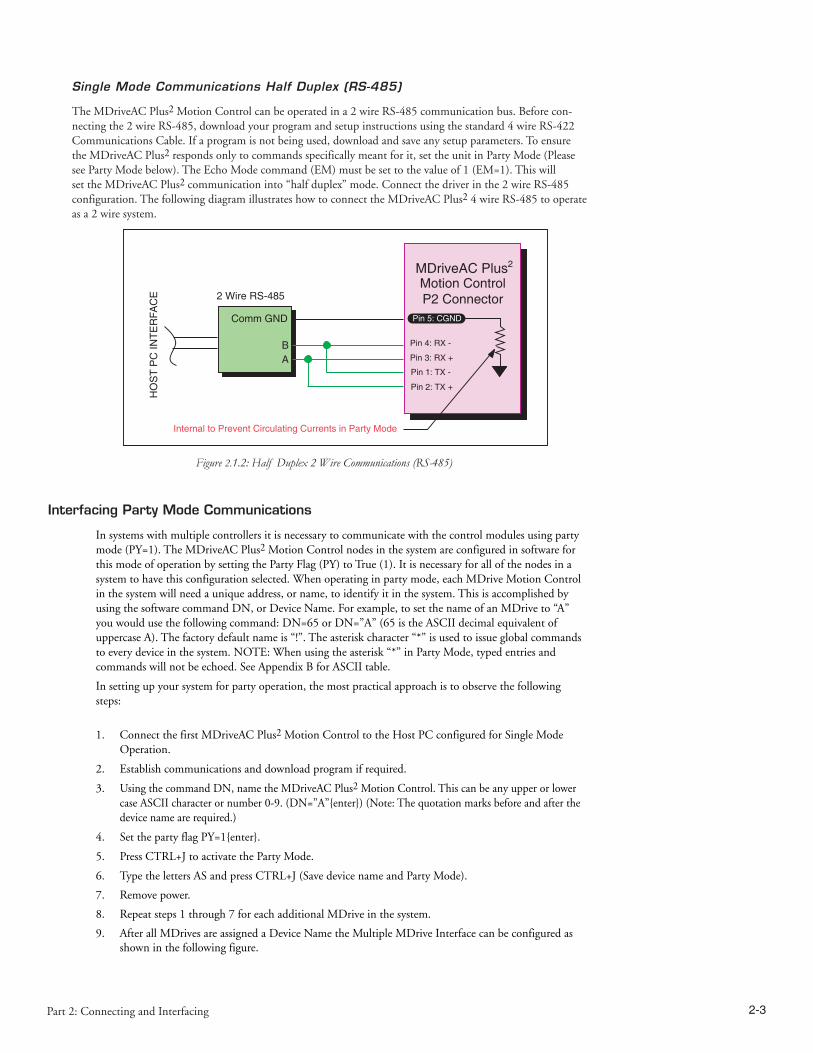
2-2 MDriveAC Plus2 Motion Control Hardware - Revision R052506 2-3Part 2: Connecting and Interfacing
Single Mode Communications Half Duplex (RS-485)
The MDriveAC Plus2 Motion Control can be operated in a 2 wire RS-485 communication bus. Before con-necting the 2 wire RS-485, download your program and setup instructions using the standard 4 wire RS-422 Communications Cable. If a program is not being used, download and save any setup parameters. To ensure the MDriveAC Plus2 responds only to commands specifically meant for it, set the unit in Party Mode (Please see Party Mode below). The Echo Mode command (EM) must be set to the value of 1 (EM=1). This will set the MDriveAC Plus2 communication into “half duplex” mode. Connect the driver in the 2 wire RS-485 configuration. The following diagram illustrates how to connect the MDriveAC Plus2 4 wire RS-485 to operate as a 2 wire system.
Interfacing Party Mode Communications
In systems with multiple controllers it is necessary to communicate with the control modules using party mode (PY=1). The MDriveAC Plus2 Motion Control nodes in the system are configured in software for this mode of operation by setting the Party Flag (PY) to True (1). It is necessary for all of the nodes in a system to have this configuration selected. When operating in party mode, each MDrive Motion Control in the system will need a unique address, or name, to identify it in the system. This is accomplished by using the software command DN, or Device Name. For example, to set the name of an MDrive to “A” you would use the following command: DN=65 or DN=”A” (65 is the ASCII decimal equivalent of uppercase A). The factory default name is “!”. The asterisk character “*” is used to issue global commands to every device in the system. NOTE: When using the asterisk “*” in Party Mode, typed entries and commands will not be echoed. See Appendix B for ASCII table.
In setting up your system for party operation, the most practical approach is to observe the following steps:
1. Connect the first MDriveAC Plus2 Motion Control to the Host PC configured for Single Mode Operation.
2. Establish communications and download program if required.
3. Using the command DN, name the MDriveAC Plus2 Motion Control. This can be any upper or lower case ASCII character or number 0-9. (DN=”A”enter) (Note: The quotation marks before and after the device name are required.)
4. Set the party flag PY=1enter.
5. Press CTRL+J to activate the Party Mode.
6. Type the letters AS and press CTRL+J (Save device name and Party Mode).
7. Remove power.
8. Repeat steps 1 through 7 for each additional MDrive in the system.
9. After all MDrives are assigned a Device Name the Multiple MDrive Interface can be configured as shown in the following figure.
Figure 2.1.2: Half Duplex 2 Wire Communications (RS-485)
HO
ST
PC
INTE
RFA
CE 2 Wire RS-485
Comm GND
BA
100Ω
MDriveAC Plus2
Motion ControlP2 Connector
Pin 3: RX +
Pin 4: RX -
Pin 2: TX +
Pin 1: TX -
Pin 5: CGND
Internal to Prevent Circulating Currents in Party Mode

2-4 MDriveAC Plus2 Motion Control Hardware - Revision R052506 2-5Part 2: Connecting and Interfacing
Ω
Ω
Ω
Figure 2.1.3: RS-485 Interface, Multiple MDriveAC Plus2Motion Control System
Data Cable Termination Resistors
Data Cable lengths greater than 15 feet (4.5 meters) are susceptible to signal reflection and/or noise. IMS recommends 120 Ω termination resistors in series with 0.1µf capacitors at both ends of the Data Cables. An ex-ample of resistor placement is shown in Figure 2.1.3 above. For systems with Data Cables 15 feet (4.5 meters) or less, the termination resistors are generally not required.
MDriveAC Plus2 Motion Control Communication Format
The following communication formats, used by MDriveAC Plus2 Motion Control (MDI) units, began with firmware version 1.043.
The contents between the symbols are transmitted.0D Hex equivalent for a CR (Carriage Return).0A Hex equivalent for a LF (Line Feed).DN Represents the Device Name being sent.CS Check Sum; ACK 06 Hex; NAK 15 Hex EM = Echo Mode; PY = PartY Mode; CK= ChecK sum
The word command represents the immediate command sent to the MDI.
Command Execution Time (CET) is the time the MDI takes to execute a command. This varies from com-mand to command and usually is in the 1-5 millisecond range.
MDriveAC Plus2 Motion Control (MDI) Response to Echo Mode
Dependent on how the Echo Mode (EM) is set in conjunction with Party Mode (PY) and Check Sum (CK), the MDI will respond differently. The following tables illustrate the various responses based on how the EM, PY and CK parameters are set.

2-4 MDriveAC Plus2 Motion Control Hardware - Revision R052506 2-5Part 2: Connecting and Interfacing
Parameter Setting Transmission to MDI MDI Initial Response MDI Final
Response Notes
EM=0 & PY=0 CK=0 (command) (D)
(command)Echoed back one character at a time as the character is
entered.
CET (0D) (0A)>The last character
sent is the prompt >
EM=1 & PY=0 CK=0 (command) (0D) − CET (0D) (0A)The last character
sent is LF
EM=2 & PY=0 CK=0 (command) (0D) − −No response
except to PR and L commands
EM=3 & PY=0 CK=0 (command) (0D) −CET command
(0D) (0A)
Queued response. The last character
sent is the LF
Table 2.1.1: MDI Response to Echo Mode - Party and Check Sum are Zero (0)
Parameter Setting Transmission to MDI MDI Initial Response
MDI Final Response Notes
EM=0 & PY=1 CK=0 (DN) (command) (0A)
(command)Echoed back one character at a time as the character is
entered.
CET (0D) (0A)>
The last character sent is the prompt >
EM=1 & PY=1 CK=0 (DN) (command) (0A) − CET (0D) (0A)The last
character sent is LF
EM=2 & PY=1 CK=0 (DN) (command) (0A) − −
No response except to PR and L
commands
EM=3 & PY=1 CK=0 (DN) (command) (0A) −CET
command(0D) (0A)
Queued response. The last character sent is the LF
Table 2.1.2: MDI Response to Echo Mode - Party is One (1) and Check Sum is Zero (0)
Parameter Setting Transmission to MDI MDI Initial Response
MDI Final Response Notes
EM=0 & PY=0 CK=1 (DN) (command) (0A)
(command)Echoed back one character at a time as the character is
entered.
CET (0D) (0A)>
The last character sent is the prompt
>
EM=1 & PY=0 CK=1 (DN) (command) (0A) − CET (0D) (0A)The last
character sent is LF
EM=2 & PY=0 CK=1 (DN) (command) (0A) − −
No response except to PR and L
commands
EM=3 & PY=0 CK=1 (DN) (command) (0A) −CET command
(0D) (0A)
Queued response. The last character sent is the LF
Table 2.1.3: MDI Response to Echo Mode - Party is Zero (0) and Check Sum is One (1)
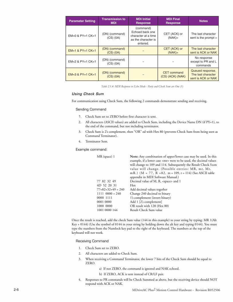
2-6 MDriveAC Plus2 Motion Control Hardware - Revision R052506 2-7Part 2: Connecting and Interfacing
Parameter Setting Transmission to MDI
MDI Initial Response
MDI Final Response Notes
EM=0 & PY=1 CK=1(DN) (command)
(CS) (0A)
(command)Echoed back one character at a time as the character is
entered.
CET (ACK) or (NAK)>
The last character sent is the prompt >
EM=1 & PY=1 CK=1(DN) (command)
(CS) (0A)−
CET (ACK) or (NAK)>
The last character sent is ACK or NAK
EM=2 & PY=1 CK=1(DN) (command)
(CS) (0A)− −
No response except to PR and L
commands
EM=3 & PY=1 CK=1(DN) (command)
(CS) (0A)−
CET command(CS) (ACK) (NAK)
Queued response. The last character
sent is ACK or NAK
Table 2.1.4: MDI Response to Echo Mode - Party and Check Sum are One (1)
Using Check Sum
For communication using Check Sum, the following 2 commands demonstrate sending and receiving.
Sending Command
1. Check Sum set to ZERO before first character is sent.
2. All characters (ASCII values) are added to Check Sum, including the Device Name DN (if PY=1), to the end of the command, but not including terminator.
3. Check Sum is 2’s complement, then “OR” ed with Hex 80 (prevents Check Sum from being seen as Command Terminator).
4. Terminator Sent.
Example command:
MR (space) 1 Note: Any combination of upper/lower case may be used. In this example, if a lower case <mr> were to be used, the decimal values will change to 109 and 114. Subsequently the Result Check Sum va lue wi l l change. (Poss ib le entr ies : MR, mr, Mr, mR.) (M = 77, R =82, m = 109, r = 114) (See ASCII table appendix in MDI Software Manual.)
77 82 32 49 Decimal value of M, R, <space> and 14D 52 20 31 Hex77+82+32+49 = 240 Add decimal values together1111 0000 = 240 Change 240 decimal to binary0000 1111 1’s complement (invert binary)0001 0000 Add 1 [2’s complement]1000 0000 OR result with 128 (Hex 80)1001 0000 144 Result Check Sum value
Once the result is reached, add the check Sum value (144 in this example) to your string by typing: MR 1(Alt Key + 0144) (Use the symbol of 0144 in your string by holding down the alt key and typing 0144). You must type the numbers from the Numlock key pad to the right of the keyboard. The numbers at the top of the keyboard will not work.
Receiving Command
1. Check Sum set to ZERO.
2. All characters are added to Check Sum.
3. When receiving a Command Terminator, the lower 7 bits of the Check Sum should be equal to ZERO.
a) If not ZERO, the command is ignored and NAK echoed.
b) If ZERO, ACK is sent instead of CR/LF pair.
4. Responses to PR commands will be Check Summed as above, but the receiving device should NOT respond with ACK or NAK.

2-6 MDriveAC Plus2 Motion Control Hardware - Revision R052506 2-7Part 2: Connecting and Interfacing
MDriveAC Plus2 Motion Control Party Mode Sample Codes
1. Download this segment of code into the first MDriveAC Plus2 Motion Control. After downloading the program to the unit, follow the Set Up instructions described earlier. Be sure to set your first unit with the unique Device Name of A (DN=”A”). The device name is case sensitive.
RC=25 ‘Run current HC=5 ‘Hold current MS=256 ‘Microstep selection A=250000 ‘Acceleration D=250000 ‘Deceleration PG 1 ‘Enter program mode S1=0,0 ‘Setup I/O 1 as an input low true LB SU ‘Start program upon power up LB AA ‘Label program AA MR 104400 ‘Move relative 104400 counts H ‘Hold program execution to complete the move LB DD ‘Label program DD BR DD,I1=0 ‘Branch to DD if I1=0 4PR “Bex 1” ‘Print device name B to execute program ‘at address 1 H 2000 ‘Hold program execution 2000 milliseconds PR “Cex 1” ‘Print device name C to execute program at ‘address 1 H 2000 ‘Hold program execution 2000 milliseconds BR AA ‘Branch to label AA EPG ‘Exit program, return to immediate mode
2. Download this segment of code into your second MDriveAC Plus2 Motion Control. After downloading the program to the unit, follow the previous party mode instructions. Be sure to set your second unit with the unique address of B (device name is case sensitive).
RC=25 ‘Run current HC=5 ‘Hold current MS=256 ‘Microstep selection A=250000 ‘Acceleration D=250000 ‘Deceleration PG 1 ‘Enter program mode LB BB ‘Label program BB MR 208000 ‘Move relative 208000 counts H ‘Hold program execution to complete the moveE PG ‘Exit program, return to immediate mode
3. Download this segment of code into your third MDriveAC Plus2 Motion Control. After downloading the program to the unit, follow the previous party mode instructions. Be sure to set your third unit with the unique address of C (device name is case sensitive).
RC=25 ‘Run current HC=5 ‘Hold current MS=256 ‘Microstep selection A=250000 ‘Acceleration D=250000 ‘Deceleration PG 1 ‘Enter program mode LB CC ‘Label program CC MR 300000 ‘Move relative 300000 counts H ‘Hold program execution to complete the move EPG ‘Exit program, return to immediate mode

2-8 MDriveAC Plus2 Motion Control Hardware - Revision R052506 2-9Part 2: Connecting and Interfacing
NOTE: When instructed to type Ctrl+J, that is the key + the
key. It will not display in the Terminal Window so be certain you press the correct keys. CtrlJ activates the Party Mode.
NOTE: Once you have activated Party Mode with the first Ctrl+J you
do not have to type it before each successive command. However, every command must be followed with a Ctrl+J.
NOTE: The asterisk (*) is a global command which addresses all
units. Since three units can not answer together, the asterisk (*) as well as other global commands will not be displayed in the Terminal Window.
MDriveAC Plus2 Motion Control Immediate Party Mode Sample Codes
Once Party Mode has been defined and set up as previously described under the heading “Multiple MDriveAC Plus2 Motion Control System (Party Mode)”, you may enter commands in the Immediate Mode in the IMS Terminal Window. Some examples follow.
Move MDrive A, B or C 10000 Steps
Assuming there are three MDrives set up in Party Mode as shown in the Sample Codes above.
n To move MDrive Unit “A”, Press Ctrl+J and then type: AMR^10000 and press Ctrl+J. MDrive Unit “A” will move 10000 steps.
n To print the position type: APR P and press Ctrl+J. The position of MDrive Unit “A” will be printed.
n To move MDrive Unit “B” type: BMR 10000 and press Ctrl+J. MDrive Unit “B” will move 10000 steps.
n To move all three MDrives at the same time type: *MR 10000 and press Ctrl+J. All MDrives will move 10000 steps.
n To change a Variable in the “C” unit type: C<variable name><number> and press Ctrl+J. The variable will be changed. To verify the change type: CPR <variable name> and press Ctrl+J. The new value will be displayed.
All Commands and Variables may be programmed in this manner.
n To take an MDrive out of Party Mode type: <device name>PY=0 and press Ctrl+J. That unit will be taken out of Party Mode. To take all units out of Party Mode type: *PY=0 and press Ctrl+J. All units will be taken out of Party Mode.

2-8 MDriveAC Plus2 Motion Control Hardware - Revision R052506 2-9Part 2: Connecting and Interfacing
SECTION 2.2 Interfacing and Using the MDriveAC Plus2 Motion Control I/O
The MDriveAC Plus2 Motion Control Digital I/O
The MDriveAC Plus2 Motion Control product line is available with two digital I/O configurations: 8 Point General Purpose I/O and Optional Remote Encoder.
The digital I/O may be defined as either active HIGH or active LOW. When the I/O is configured as active HIGH, the level is +5 to +24 VDC and the state will be read/set as a “1”. If the level is 0 VDC, then the state will be read/set as “0”. Inversely, if configured as active LOW, then the state of the I/O will be read/set as a “1” when the level is LOW, and “0” when the level is HIGH. The active HIGH/LOW state is configured by the third parameter of the I/O Setup (S1-4, S9-12) variable. The goal of this I/O configuration scheme is to maxi-mize compatibility between the MDriveAC Plus2 Motion Control and standard sensors and switches.
8 I/O Configuration
Low I/O Group................................................................. IO1, IO2, IO3, IO4 (Sinking Sourcing, Outputs/Inputs)High I/O Group................................................................ IO9, IO10, IO11, IO12 (Sinking Sourcing, Outputs/Inputs)Dedicated I/O ................................................................... Step/Clock Input, Step/Direction I/O, Capture Input/Trip Output
Remote Encoder Configuration
Low I/O Group................................................................. IO1, IO2, IO3, IO4 (Sinking Sourcing, Outputs/Inputs)Encoder Inputs..................................................................Differential EncoderDedicated I/O ................................................................... Step/Clock Input, Step/Direction I/O, Capture Input/Trip Output
8 I/O Configuration
The MDriveAC Plus2 Motion Control is equipped with a set of eight I/O — (8) sinking or sourcing 0 to +24 VDC inputs or (8) sinking or sourcing +12 to +24 VDC outputs, which may be programmed individually as either general purpose or dedicated inputs or outputs, or collectively as a group. The eight I/O consist of two separate banks of four points: Bank 1: IO1 - IO4, Bank 2: IO9 - IO12.
Uses of the Digital I/O
The I/O may be utilized to receive input from external devices such as sensors, switches or PLC outputs. When configured as outputs, devices such as relays, solenoids, LEDs and PLC inputs may be controlled from the MDriveAC Plus2 Motion Control.
Each I/O point may be individually programmed to any one of 9 dedicated input functions, 4 dedicated output functions, or as general purpose inputs or outputs. The I/O may be addressed individually or as a group. The active state of the line or group may also be set. All of these possible functions are accomplished with the I/O Setup Variable (S1-4, S9-12).
When the level is HIGH the active HIGH/LOW state is configured by the second parameter of the I/O Setup (S1-4, S9-12) variable. The goal of this I/O configuration scheme is to maximize compatibility between the MDriveAC Plus2 Motion Control and standard sensors and switches.
NOTE: If the unit purchased has the remote encoder
option, the additional points become dedicated to encoder functions!
INPUTS
• Sensors• Switches• PLC Outputs• Outputs of Additional System MDrive's
OUTPUTS
• Relays• Solenoids• LED's• PLC Inputs• Inputs of Additional System MDrive's
Figure 2.2.1: Uses for the Digital I/O

2-10 MDriveAC Plus2 Motion Control Hardware - Revision R052506 2-11Part 2: Connecting and Interfacing
MDriveAC Plus2 Motion Control Digital Input Functions
The MDriveAC Plus2 Motion Control inputs may be interfaced to a variety of sinking or sourcing devices. An input may be programmed to be a general purpose user input, or to one of nine dedicated input functions. These may then be programmed to have an active state of either HIGH or LOW.
The inputs are configured using the “S” Variable (See MDrive Motion Control Sofware Reference Manual for precise details on this command). The command is entered into the IMS terminal or program file as S<IO point>=<IO Type>,<Active State><Sink/Source>.
Example:
S9=3,1,0 ‘set IO point 9 to be a Limit- input, Active HIGH, SourcingS3=0,0,1 ‘set IO Point 3 to be a General Purpose input, Active LOW, ‘Sinking
Programmable Input Functions
The following table lists the programmable input functions of the MDrive Motion Control.
MDriveAC Plus2 Motion Control Input Functions
Parameter(S1-S4, S9-S12) Function Active Sink/Source
0 General Purpose 0/1 0/1
1 Home 0/1 0/1
2 Limit + 0/1 0/1
3 Limit – 0/1 0/1
4 GO 0/1 0/1
5 Soft Stop 0/1 0/1
6 Pause 0/1 0/1
7 Jog + 0/1 0/1
8 Jog – 0/1 0/1
11 Reset 0/1 0/1
Table 2.2.1: Programmable Input Functions
Dedicated Input Functions
MDriveAC Plus2 Motion Control Dedicated Input Functions
Parameter(S7, S8) Function Active
33 Step/Direction 0/1
34 Quadrature 0/1
35 Up/Down 0/1
Parameter(S13) Function Active
60 High Speed Capture 0/1
Table 2.2.2: Dedicated Input Functions
Active States Defined
The Active State determines at what voltage level the input will be active.
Active HIGH ...................................................................... The input will be active when +5 top +24 VDC is applied to the input.Active LOW........................................................................ The input will be active when it is gorunded (0 VDC).

2-10 MDriveAC Plus2 Motion Control Hardware - Revision R052506 2-11Part 2: Connecting and Interfacing
Active LOW example:
IO 1 is to be configured as a Jog– input which will activate when a switch is toggled to ground (Sinking Input):
S1=8,0,0 ‘set IO point 1 to Jog–, Active LOW, Sinking
Active HIGH example:
IO 4 is to be configured as a Home input which will activate when instructed by a PLC (+24VDC Sourcing Input):
S4=1,1,1 ‘set IO point 1 to Home, Active HIGH, Sourcing
MDriveAC Plus2 Motion Control Digital Output Functions
The MDriveAC Plus2 Motion Control Outputs may be configured as general purpose or set to one of two dedicated functions: Fault or Moving. These outputs will sink up to 600 mA (one channel of two banks) and may be connected to an external VDC source. See Output Functions Table and I/O Ratings Table.
The outputs are set using the “S” comand (See MDrive Motion Control Sofware Reference Manual for precise details on this command). The command is entered into the IMS terminal or program file as S<IO point>=<IO Type>,<Active State><Sink/Source>.
Example:
S9=17,1,0 ‘set IO point 9 to be a Moving Output, Active HIGH, SinkingS3=18,0,0 ‘set IO Point 3 to be a Fault Output, Active LOW, Sinking
Programmable Output Functions
The MDriveAC Plus2 Motion Control Output functions may be programmed to be a general purpose user output or to one of five output functions.
MDriveAC Plus2 Motion Control Output Functions
Parameter(S1-S4, S9-S12) Function Active Sink/Source
16 General Purpose User 0/1 0/1
17 Moving 0/1 0/1
18 Fault 0/1 0/1
19 Stall 0/1 0/1
20 Velocity Changing 0/1 0/1
Table 2.2.3: Programmable Output Functions
Dedicated Output Functions
MDriveAC Plus2 Motion Control Dedicated Output Functions
Parameter(S7, S8) Function Active
49 Step/Direction 0/1
50 Quadrature 0/1
51 Up/Down 0/1
Parameter(S13) Function Active
61 High Speed Trip 0/1
Table 2.2.4: Dedicated Output Functions

2-12 MDriveAC Plus2 Motion Control Hardware - Revision R052506 2-13Part 2: Connecting and Interfacing
I/O1
I/O9
I/O10
I/O11
I/O12
STEP/CLK I/O
DIR/CLK I/O
CH A +
CH A -
CH B +
CH B -
INDEX +
INDEX -
I/O2
I/O3
I/O4
ANALOG IN
I/O POWER
I/O GROUND
CAPTURE/TRIP
8 I/OCONFIGURATION
LowGroup
HighGroup
USER SUPPLIEDREMOTE ENCODER
OPTION*-OR-
*See Appendix: MDrivePlus Closed Loop Control for encoder connection and configuration information
Pin 11Pin 10
Pin 14Pin 15
Pin 4Pin 16Pin 9Pin 17
Pin 1Pin 18Pin 2Pin 13
Pin 3Pin 5
MDriveACPlus2
MotionControl
MDriveAC Plus2 Motion Control I/O Ratings
MDriveAC Plus2 I/O Ratings
MDriveAC Plus2 Output Voltage (IOPWR) Rating +12 to +24 VDC (Sourcing) | 0 to +24 VDC (Sinking)
Load Rating* (equal current per I/O Point)
* Heatsink Temp = 85C
I/O State I Continuous I Peak (D=0.84)
1 on, 3 off 550 mA 600 mA
2 on, 2 off 390 mA 425 mA
3 on, 1 off 320 mA 350 mA
4 on, 0 off 275 mA 300 mA
To compute FET dissipation for unequal loads, calculate the FET power for each I/O not to exceed 425 mW.
Continuous Current FET Power = Icont2 x 1.4
Peak Current FET Power = Ipeak2 x D x 1.4
Duty Cycle (D =T on /T period) = ≤ 1.0 seconds at 85˚C heatsink temperature.
Protection Ratings
Independent Over-temperature
Current Limit 0.6A to 1.2 A
Clamp +45V, -20V
Table 2.2.5: MDriveAC Plus2 Motion Control I/O and Protection Ratings
MDriveAC Plus2 Motion Control I/O Connection Map
Figure 2.2.2: I/O Connection Map
WARNING! External Current Limiting may be required to ensure
that the current per I/O point does not exceed rated limits.
Be aware that the current rating is dependant on the number of active points in the group. If all 4 I/O, either 1-4 or 9-12 are active the max continuous current is 275mA..

2-12 MDriveAC Plus2 Motion Control Hardware - Revision R052506 2-13Part 2: Connecting and Interfacing
NOTE: Advanced I/O interface circuit diagrams and
application examples are available in Appendix D: I/O Applications Guide.
General Purpose I/O Usage Examples — Enhanced I/O Set
The MDriveAC Plus2 models add the functionality of either an additional 4 I/O points or an optional interface for a user-defined remote encoder. Additionally, the I/O points, when configured as outputs have the added functionality of being configured as sinking or sourcing outputs.
The circuit examples below illustrate possible interface examples for using the MDriveAC Plus2 Motion Con-trol Digital I/O. Additional diagrams and code samples are available in Appendix D: I/O Applications Guide.
The code samples included with these examples will also serve to introduce the user to MDriveAC Plus Mo-tion Control programming. Please reference the MDrive Motion Control (MDI) software reference for more information on the Instructions, Variables and Flags that make up the MDI command set as well as material on setting up and using the IMS Terminal.
Input Interface Example - Switch Input Example (Sinking Input)
The following circuit example shows a switch connected between an I/O point and I/O Ground.
Code Sample
For the code sample, this switch will be set up as a G0 sinking input, active when low. When pressed, the switch will launch the program beginning at address1 in MDrive memory:
***Setup Variables***Sx=4,0,0 ‘set IO point x to be a G0 input, active when LOW, sinking
****Program***PG1MR 20000 ‘Move +20000 steps relative to current positionH ‘Hold program execution until motion completesMR -20000 ‘Move -20000 stepsH ‘Hold program execution until motion completesEPG ‘End program, exit program mode
Internal to MDriveAC Plus2
Internalpull-upvoltage
detectlogic
24.9k ohms
100k ohms
3.3 V
The internal pull-up voltagecannot provide output
current / voltage
IOPWR
IOGND
Iil
65 - 160 uA
IOx
Vih = 2.31 VVil = 0.99 V
Threshold (nom) = 1.5 VIil = 100 µA
Switch Input, Sinking Sinking Input Equivalent Circuit
Figure 2.2.3: Switch Interface to Input, Sinking

2-14 MDriveAC Plus2 Motion Control Hardware - Revision R052506 2-15Part 2: Connecting and Interfacing
Input Interface Example - Switch Input Example (Sourcing Input)
The following circuit example shows a switch connected between an I/O point and a voltage supply which will source the input to perform a function.
Code Sample
For the code sample, the switch will be set up as a Soft Stop sourcing input, active when HIGH. When pressed, the switches will stop the motor.
S1=5,1,1 ‘set IO point 1 to be a Soft Stop input, active when HIGH, ‘sourcingSL 200000 ‘enter this to slew the motor at 200000 µsteps/sec
When the switch is depressed the motor will decelerate to a stop.
Figure 2.2.4 Sourcing Input Example using a Push Button Switch
Internal to MDriveAC Plus2
Switch Input, Sourcing
Internalpull-upvoltage
detectlogic
40 - 135 uA
24.9k ohms
100k ohms
3.3 V
The internal pull-up voltagecannot provide output
current / voltage
IOPWR
IOx
IOGND
Iih
Vih = 2.31 VVil = 0.99 V
Threshold (nom) = 1.5 VIih = -1.24 mA

2-14 MDriveAC Plus2 Motion Control Hardware - Revision R052506 2-15Part 2: Connecting and Interfacing
Output Interface Example (Sinking Output)
The following circuit example shows a load connected to an I/O point that will be configured as a sinking output.
Code Sample
For the code sample, the load will be an LED. The I/O point will be configured such that the LED will be unlit while the velocity is changing. Use the switch set-up from the previous input, modified to be sinking, example to soft stop the motor.
S1=5,0,0 ‘set IO point 1 to be a Soft Stop input, active when LOW, ‘sinking.S1=20,0,0 ‘set IO point 2 to be a Velocity Changing output, active ‘when LOWSL 2000000 ‘enter this to slew the motor at 200000 µsteps/sec
While the motor is accelerating the LED will be dark, but will light up when the motor reaches a constant velocity. When the Soft Stop switch is depressed the motor will begin to decelerate, the LED will go dark again while velocity is changing.
Sinking Output
Figure 2.2.5: Sinking Output Example

2-16 MDriveAC Plus2 Motion Control Hardware - Revision R052506 2-17Part 2: Connecting and Interfacing
Output Interface Example (Sourcing Output)
The following circuit example shows a load connected to an I/O point that will be configured as a sourcing output.
Code Sample
For the code sample, the load will be a relay. The output will be configured to be a General Purpose user out-put that will be set active when a range of motion completes.
******Setup Variables******S1=16,1,1 ‘set IO point 1 to be a user output, active when HIGH, ‘sourcing.
******Program******PG 100 ‘Enter program at address 100MR 2000000 ‘Move some distance in the positive directionH ‘Hold execution until motion completesMR -1000000 ‘Move some distance in the negative directionH ‘Hold execution until motion completesO1=1 ‘Set output 1 HIGH
Enter EX 100 to execute the program, the motion will occur and the output will set high.
Figure 2.2.6: Sourcing Output Example

2-16 MDriveAC Plus2 Motion Control Hardware - Revision R052506 2-17Part 2: Connecting and Interfacing
Dedicated Digital I/O - Enhanced I/O Set
Step/Direction/Clock I/O
These dedicated I/O lines are used to receive clock inputs from an external device or provide clock outputs to an external device such as a counter or a second MDriveAC Plus2 in a system. The Clock I/O can be config-ured as one of three clock types using the S7 and S8 variable:
1. Step/Direction
2. Quadrature
3. Up/Down
Step/Direction
The Step/Direction function would typically be used to receive step and direction instructions from a second system MDriveAC Plus2 or secondary controller. When configured as outputs the MDriveAC Plus2 Motion Control can provide step and direction control to another system drive for electronic gearing applications.
Quadrature
The Quadrature clock function would typically be used for following applications where the MDriveAC Plus2 would either be a master or slave in an application that would require two MDrives to move the same distance and speed.
Up/Down
The Up/Down clock would typically be used in a dual-clock direction control application, or to increment/decrement an external counter.
Capture/Trip
The Capture Input/Trip Output point is a high speed I/O point which can be used for time critical events in motion applications.
Capture Input
When configured as a capture input I/O point 13 has programmable filtering with a range of 50nS to 12.9 µS and has a resolution of 32 bits.
To configure the Capture input
S13=60,<0/1> ‘configure IO13 as a capture input, <active HIGH/LOW>FC <0-9> ‘set input filtering to <range>
Trip Output
When configured as a trip output I/O 13 trip speed is 150 nS with 32 bit resolution.
To configure the Trip output
S13=61,<0/1> ‘configure IO13 as a trip output, <active HIGH/LOW>
NOTE: When using the MDriveAC Plus2 with the
external encoder option, the step an direction I/O are not available! These I/O points become Index + and Index-. See Appendix: MDriveAC Plus2 Motion Control Closed Loop Control for encoder connection and configuration information.
Step Clock
Direction
Channel A
Channel B
CW
CCW
Step/Direction Function
Quadrature Function
Up/Down Function
Input: S<7-8>=33, <active state>Output: S<7-8>=49,<active state>
Input: S<7-8>=34, <active state>Output: S<7-8>=50,<active state>
Input: S<7-8>=35, <active state>Output: S<7-8>=51,<active state>
Figure 2.2.7: MDriveAC Plus2 Motion Control Clock Functions
NOTE: Advanced I/O interface circuit diagrams and
application examples are available in Appendix I/O Applications Guide.

2-18 MDriveAC Plus2 Motion Control Hardware - Revision R052506 2-19Part 2: Connecting and Interfacing
Interfacing the Analog Input
The analog input of the MDriveAC Plus2 Motion Control is configured from the factory as a 0 to 5V, 10 bit resolution input (S5=9). This offers the user the ability to receive input from temperature, pressure, or other forms of sensors, and then control events based upon the input.
The value of this input will be read using the I5 instruction, which has a range of 0 to 1023, where 0 = 0 volts and 1024 = 5.0 volts. The MDriveAC Plus2 Motion Control may also be configured for a 4 to 20 mA or 0 to 20 mA Analog Input (S5 = 10).
Sample Usage
‘***********Main Program**************
S5=9,0 ‘set analog input to read variable voltage (0 to +5VDC)PG 100 ‘start prog. address 100LB A1 ‘label program A1CL A2, I5<500 ‘Call Sub A2, If I5 is less than 500CL A3, I5>524 ‘Call Sub A3, If I5 is greater than 524BR A1 ‘loop to A1
‘***********Subroutines**************
LB A2 ‘label subroutine A2MA 2000 ‘Move Absolute 2000 stepsH ‘Hold program execution until motion ceasesRT ‘return from subroutine
LB A3 ‘label subroutine A3MA -2000 ‘Move Absolute -2000 stepsH ‘Hold program execution until motion ceasesRT ‘return from subroutineE ‘EndPG ‘Exit program
Figure 2.2.8: Analog Input - Voltage Mode

2-18 MDriveAC Plus2 Motion Control Hardware - Revision R052506 2-19Part 2: Connecting and Interfacing
Figure 2.2.9: Analog Input - Current Mode

2-20 MDriveAC Plus2 Motion Control Hardware - Revision R052506
Page Intentionally Left Blank

A-1Appendices
TMExcellence in Motion
Appendices
TM
Appendix A: MDriveAC Plus2 Motion Control Motor Performance
Appendix B: Planetary Gearbox Specification and Application Guide
Appendix C: I/O Application Guide
Appendix D: MDriveAC Plus2 Motion Control Closed Loop Control
Appendix E: Optional Cables and Cordsets

A-2 MDriveAC Plus2 Motion Control Hardware - Revision R052506 A-3Appendices
Page Intentionally Left Blank

A-2 MDriveAC Plus2 Motion Control Hardware - Revision R052506 A-3Appendices
appendix A MDriveAC Plus2 Motion Control Motor Performance
MDrive34AC Plus2 Motion Control
Speed-Torque Curves
Figure A.1: MDrive34AC Plus2 120VAC Motion Control Speed-Torque Curves
MDrive34AC – 120VAC
MDrive34AC – 240VAC
Figure A.2: MDrive34AC Plus2 240VAC Motion Control Speed-Torque Curves
Motor Specifications
Single Length
Holding Torque............................................................................................... 330 oz-in/233 N-cmDetent Torque................................................................................................. 10.9 oz-in/7.7 N-cmRotor Inertia ...................................................................................0.01416 oz-in-sec2/1.0 kg-cm2
Weight (Motor + Driver)............................................................................................. 3.8 lb/2.9 kg

A-4 MDriveAC Plus2 Motion Control Hardware - Revision R052506 A-5Appendices
Double Length
Holding Torque............................................................................................... 500 oz-in/353 N-cmDetent Torque............................................................................................. 14.16 oz-in/14.0 N-cmRotor Inertia ...................................................................................0.02266 oz-in-sec2/1.6 kg-cm2
Weight (Motor + Driver)............................................................................................. 5.2 lb/3.5 kg
Triple Length
Holding Torque............................................................................................... 750 oz-in/529 N-cmDetent Torque............................................................................................. 19.83 oz-in/10.0 N-cmRotor Inertia ...................................................................................0.04815 oz-in-sec2/3.4 kg-cm2
Weight (Motor + Driver)............................................................................................. 8.6 lb/5.0 kg
MDrive42AC Plus2 Motion Control
Speed-Torque Curves
MDrive42AC – 120VAC
MDrive42AC – 240VAC
Figure A.3: MDrive42AC Plus2 120VAC Motion Control Speed-Torque Curves
Figure A.4: MDrive42AC Plus2 240VAC Motion Control Speed-Torque Curves

A-4 MDriveAC Plus2 Motion Control Hardware - Revision R052506 A-5Appendices
Motor Specifications
Single Length
Holding Torque............................................................................................. 1147 oz-in/810 N-cmDetent Torque..................................................................................................... 35 oz-in/25 N-cmRotor Inertia .....................................................................................0.0917 oz-in-sec2/6.5 kg-cm2
Weight (Motor + Driver)....................................................................................... 14.07 lb/6.38 kg
Double Length
Holding Torque........................................................................................... 2294 oz-in/1620 N-cmDetent Torque..................................................................................................... 84 oz-in/59 N-cmRotor Inertia ......................................................................................0.1833 oz-in-sec2/13 kg-cm2
Weight (Motor + Driver).......................................................................................21.25 oz/9.64 kg

A-6 MDriveAC Plus2 Motion Control Hardware - Revision R052506 A-7Appendices
Appendix BMDrive with Planetary Gearbox
Section Overview
This section contains guidelines and specifications for MDrives equipped with an optional Planetary Gearbox, and may include product sizes not relevant to this manual.
Shown are:
n Product Overview
n Selecting a Planetary Gearbox
n Mechanical Specifications
Product Overview
All gearboxes are factory installed.
Mode of Function
Optional Planetary Gearbox operate as their name implies: the motor-driven sun wheel is in the center, transmitting its movement to three circumferential planet gears which form one stage. They are arranged on the bearing pins of a planet carrier. The last planet carrier in each sequence is rigidly linked to the out-put shaft and so ensures the power transmission to the output shaft. The planet gears run in an internally toothed outer ring gear.
Service Life
Depending on ambient and environmental conditions and the operational specification of the driving system, the useful service life of a Planetary Gerabox is up to 10,000 hours. The wide variety of potential applications prohibits generalizing values for the useful service life.
Lubrication
All Planetary Gearbox are grease-packed and therefore maintenance-free throughout their life. The best possible lubricant is used for our MDrive/Planetary Gearbox combinations.
Mounting Position
The grease lubrication and the different sealing modes allow the Planetary Gearbox to be installed in any position.
Operating Temperature
The temperature range for the Planetary Gearbox is between –30 and +140° C. However, the temperature range recommended for the Heat Sink of the MDrive is 0 to +85º C.
Overload Torque
The permitted overload torque (shock load) is defined as a short-term increase in output torque, e.g. dur-ing the start-up of a motor. In these all-metal Planetary Gearbox, the overload torque can be as much as 1.5 times the permitted output torque.
Available Planetary Gearbox
The following lists available Planetary Gearbox, diameter and corresponding MDrive.
Gearbox Diameter MDrive
81 mm MDrive34
105 or 120 mm MDrive42

A-6 MDriveAC Plus2 Motion Control Hardware - Revision R052506 A-7Appendices
Selecting a Planetary Gearbox
There are many variables and parameters that must be considered when choosing an appropriate reduction ratio for an MDrive with Planetary Greabox. This Addendum includes information to assist in determining a suit-
able combination for your application.
Calculating the Shock Load Output Torque (TAB)
Note: The following examples are based on picking “temporary variables” which may be adjusted.
The shock load output torque (TAB) is not the actual torque generated by the MDrive and Planetary Gearbox combination, but is a calculated value that includes an operating factor (CB) to compensate for any shock loads applied to the Planetary Gearbox due to starting and stopping with no acceleration ramps, payloads and directional changes. The main reason the shock load output torque (TAB) is calculated is to ensure that it does not exceed the maximum specified torque for a Planetary Gearbox.
Note: There are many variables that affect the calculation of the shock load output torque. Motor speed, motor voltage, motor torque and reduction ratio play an important role in determining shock load output torque. Some variables must be approximated to perform the calculations for the first time. If the result does not meet your requirements, change the variables and re-calculate the shock load output torque.
Use the equation compendium below to calculate the shock load output torque.
Factors
i = Reduction Ratio - The ratio of the Planetary Gearbox.
nM = Motor Speed - In Revolutions Per Minute (Full Steps/Second).
nAB = Output Speed - The speed at the output shaft of the Planetary Gearbox.
TN = Nominal Output Torque - The output torque at the output shaft of the Planetary Gearbox.
TM = Motor Torque - The base MDrive torque. Refer to MDrive Speed Torque Tables.
η = Gear Efficiency - A value factored into the calculation to allow for any friction in the gears.
TAB = Shock Load Output Torque - A torque value calculated to allow for short term loads greater than the nominal output torque.
CB = Operating Factor - A value that is used to factor the shock load output torque.
sf = Safety Factor - A 0.5 to 0.7 factor used to create a margin for the MDrive torque requirement.
Reduction Ratio
Reduction ratio (i) is used to reduce a relatively high motor speed (nM) to a lower output speed (nAB).
With: i = nM ÷ nAB or: motor speed ÷ output speed = reduction ratio
Example:
The required speed at the output shaft of the Planetary Gearbox is 90 RPM.
You would divide motor speed (nM) by output speed (nAB) to calculate the proper gearbox ratio.
The MDrive speed you would like to run is approximately 2000 full steps/second or 600 RPM.
NOTE: In reference to the MDrive speed values, they are given in full steps/second on the Speed/Torque Tables. Most speed specifications for the Planetary Gearbox will be given in RPM (revolutions per min-ute). To convert full steps/second to RPM, divide by 200 and multiply by 60.
Where: 200 is the full steps per revolution of a 1.8° stepping motor.
2000 full steps/second ÷ 200 = 10 RPS (revolutions per second) × 60 Seconds = 600 RPM
For the Reduction Ratio (i), divide the MDrive speed by the required Planetary Gearbox output speed.
600 RPM ÷ 90 = 6.67:1 Reduction Ratio
Referring to the Available Ratio Table at the end of this section, the reduction ratio (i) of the Planetary Gearbox will be 7:1. The numbers in the left column are the rounded ratios while the numbers in the right column are the actual ratios. The closest actual ratio is 6.75:1 which is the rounded ratio of 7:1. The slight difference can be made up in MDrive speed.
Note: The MDrive23 and the numbers and values used in these
examples have been chosen randomly for demonstration purposes. Be certain you obtain the correct data for the MDrive you have purchased.
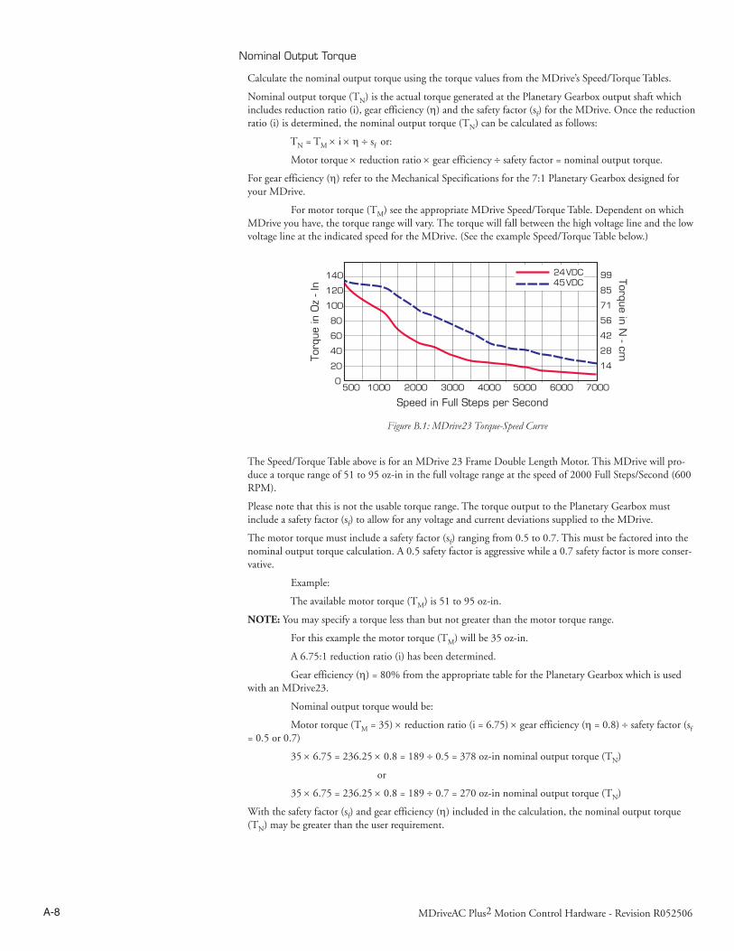
A-8 MDriveAC Plus2 Motion Control Hardware - Revision R052506 A-9Appendices
Nominal Output Torque
Calculate the nominal output torque using the torque values from the MDrive’s Speed/Torque Tables.
Nominal output torque (TN) is the actual torque generated at the Planetary Gearbox output shaft which includes reduction ratio (i), gear efficiency (η) and the safety factor (sf) for the MDrive. Once the reduction ratio (i) is determined, the nominal output torque (TN) can be calculated as follows:
TN = TM × i × η ÷ sf or:
Motor torque × reduction ratio × gear efficiency ÷ safety factor = nominal output torque.
For gear efficiency (η) refer to the Mechanical Specifications for the 7:1 Planetary Gearbox designed for your MDrive.
For motor torque (TM) see the appropriate MDrive Speed/Torque Table. Dependent on which MDrive you have, the torque range will vary. The torque will fall between the high voltage line and the low voltage line at the indicated speed for the MDrive. (See the example Speed/Torque Table below.)
The Speed/Torque Table above is for an MDrive 23 Frame Double Length Motor. This MDrive will pro-duce a torque range of 51 to 95 oz-in in the full voltage range at the speed of 2000 Full Steps/Second (600 RPM).
Please note that this is not the usable torque range. The torque output to the Planetary Gearbox must include a safety factor (sf) to allow for any voltage and current deviations supplied to the MDrive.
The motor torque must include a safety factor (sf) ranging from 0.5 to 0.7. This must be factored into the nominal output torque calculation. A 0.5 safety factor is aggressive while a 0.7 safety factor is more conser-vative.
Example:
The available motor torque (TM) is 51 to 95 oz-in.
NOTE: You may specify a torque less than but not greater than the motor torque range.
For this example the motor torque (TM) will be 35 oz-in.
A 6.75:1 reduction ratio (i) has been determined.
Gear efficiency (η) = 80% from the appropriate table for the Planetary Gearbox which is used with an MDrive23.
Nominal output torque would be:
Motor torque (TM = 35) × reduction ratio (i = 6.75) × gear efficiency (η = 0.8) ÷ safety factor (sf = 0.5 or 0.7)
35 × 6.75 = 236.25 × 0.8 = 189 ÷ 0.5 = 378 oz-in nominal output torque (TN)
or
35 × 6.75 = 236.25 × 0.8 = 189 ÷ 0.7 = 270 oz-in nominal output torque (TN)
With the safety factor (sf) and gear efficiency (η) included in the calculation, the nominal output torque (TN) may be greater than the user requirement.
140
120
100
80
60
40
20
0
99
85
71
56
42
28
14
500 1000 2000 3000 4000 5000 6000 7000
Speed in Full Steps per Second
Torq
ue in
Oz
- In
Torque in N - cm
24VDC45VDC
Figure B.1: MDrive23 Torque-Speed Curve

A-8 MDriveAC Plus2 Motion Control Hardware - Revision R052506 A-9Appendices
Shock Load Output Torque
The nominal output torque (TN) is the actual working torque the Planetary Gearbox will generate. The shock load output torque (TAB) is the additional torque that can be generated by starting and stopping with no acceleration ramps, payloads, inertia and directional changes. Although the nominal output torque (TN) of the Planetary Gearbox is accurately calculated, shock loads can greatly increase the dy-namic torque on the Planetary Gearbox.
Each Planetary Gearbox has a maximum specified output torque. In this example a 7:1 single stage MD23 Planetary Gearbox is being used. The maximum specified output torque is 566 oz-in. By calculat-ing the shock load output torque (TAB) you can verify that value is not exceeding the maximum specified output torque.
When calculating the shock load output torque (TAB), the calculated nominal output torque (TN) and the operating factor (CB) are taken into account. CB is merely a factor which addresses the different working conditions of a Planetary Gearbox and is the result of your subjective appraisal. It is therefore only meant as a guide value. The following factors are included in the approximate estimation of the operating factor (CB):
n Direction of rotation (constant or alternating)
n Load (shocks)
n Daily operating time
Note: The higher the operating factor (CB), the closer the shock load output torque (TAB) will be to the maximum specified output torque for the Planetary Gearbox. Refer to the table below to calculate the approximate operating factor (CB).
With the most extreme conditions which would be a CB of 1.9, the shock load output torque (TAB) is over the maximum specified torque of the Planetary Gearbox with a 0.5 safety factor but under with a 0.7 safety factor.
The nominal output torque (TN) × the operating factor (CB) = shock load or maximum output torque (TAB).
With a 0.5 safety factor, the shock load output torque is greater than the maximum output torque specifi-cation of the MDrive23 Planetary Gearbox.
(378 × 1.9 = 718.2 oz-in.)
With a 0.7 safety factor the shock load output torque is within maximum output torque specification of the MDrive23 Planetary Gearbox.
(270 × 1.9 = 513 oz-in.)
The 0.5 safety factor could only be used with a lower operating factor (CB) such as 1.5 or less, or a lower motor torque.
Note: All published torque specifications are based on CB = 1.0. Therefore, the shock load output torque (TAB) = nominal output torque (TN).
WARNING! Excessive torque may damage your Planetary Gearbox. If the MDrive/Planetary Gearbox should hit an obstruction, especially at lower speeds (300 RPM or 1000 Full Steps/Second), the torque generated will exceed the maximum torque for the Planetary Gearbox. Precautions must be taken to ensure there are no obstructions in the system.
Determining the Operating Factor (CB)
Direction ofRotation
Load(Shocks) Daily Operating Time
3 Hours 8 Hours 24 Hours
Constant Low* CB=1.0 CB=1.1 CB=1.3
Medium** CB=1.2 CB=1.3 CB=1.5
Alternating Low† CB=1.3 CB=1.4 CB=1.6
Medium†† CB=1.6 CB=1.7 CB=1.9
* Low Shock = Motor turns in one direction and has ramp up at start.** Medium Shock = Motor turns in one direction and has no ramp up at start.† Low Shock = Motor turns in both directions and has ramp up at start.†† Medium Shock = Motor turns in both directions and has no ramp up at start.
Table B.1: Planetary Gearbox Operating Factor

A-10 MDriveAC Plus2 Motion Control Hardware - Revision R052506 A-11Appendices
System Inertia
System inertia must be included in the selection of an MDrive and Planetary Gearbox. Inertia is the resistance an object has relative to changes in velocity. Inertia must be calculated and matched to the motor inertia. The Planetary Gearbox ratio plays an important role in matching system inertia to motor inertia. There are many variable factors that affect the inertia. Some of these factors are:
n The type of system being driven.
n Weight and frictional forces of that system.
n The load the system is moving or carrying.
The ratio of the system inertia to motor inertia should be between 1:1 and 10:1. With 1:1 being ideal, a 1:1 to 5:1 ratio is good while a ratio greater than 5:1 and up to 10:1 is the maximum.
Type of System
There are many systems and drives, from simple to complex, which react differently and possess varied amounts of inertia. All of the moving components of a given system will have some inertia factor which must be included in the total inertia calculation. Some of these systems include:
n Lead screw
n Rack and pinion
n Conveyor belt
n Rotary table
n Belt drive
n Chain drive
Not only must the inertia of the system be calculated, but also any load that it may be moving or carrying. The examples below illustrate some of the factors that must be considered when calculating the inertia of a system.
Lead Screw
In a system with a lead screw, the following must be considered:
n The weight and preload of the screw
n The weight of the lead screw nut
n The weight of a table or slide
n The friction caused by the table guideways
n The weight of any parts
Preload onleadscrew
Weight oftable
Weight ofparts
Friction ofguideways
Weight ofnut
Weight ofscrew
Figure B.2: Lead Screw System Inertia Considerations

A-10 MDriveAC Plus2 Motion Control Hardware - Revision R052506 A-11Appendices
Rack and Pinion
In a system with a rack and pinion, the following must be considered:
n The weight or mass of the pinion
n The weight or mass of the rack
n The friction and/or preload between the pinion and the rack
n Any friction in the guidance of the rack
n The weight or mass of the object the rack is moving
Conveyor Belt
In a system with a conveyor belt, the following must be considered:
n The weight and size of the cylindrical driving pulley or roller
n The weight of the belt
n The weight or mass and size of the idler roller or pulley on the opposite end
n The angle or elevation of the belt
n Any load the belt may be carrying
Weight ofpinion and shaft
Preload or frictionbetween pinion and rack
Load onrack
Weight ofrack
Friction ofrack in guide
Gearbox
Motor
Weight and sizeof drive roller
Weight and sizeof idler roller
Weight ofconveyor belt
Weight ofparts
Frictionof belt
Elevation
Motor
Gearbox
Figure B.3: Rack and Pinion System Inertia Considerations
Figure B.4: Conveyor System Inertia Considerations

A-12 MDriveAC Plus2 Motion Control Hardware - Revision R052506 A-13Appendices
Rotary Table
In a system with a rotary table, the following must be considered:
n The weight or mass and size of the table
n Any parts or load the table is carrying
n The position of the load on the table, the distance from the center of the table will
effect the inertia
n How the table is being driven and supported also affects theinertia
Belt Drive
In a system with a belt drive, the following must be considered:
n The weight or mass and size of the driving pulley
n The tension and/or friction of the belt
n The weight or mass and size of the driven pulley
n Any load the system may be moving or carrying
Weight and sizeof drive pulley
Weight and sizeof driven pulley
Friction created bytension on belt
Weight ofshaft
Weight andsize of tableWeight and position
of parts on table
The position of parts relativeto the center of the
rotary table is important
Friction of anybearing or support
Motor
Gearbox
Figure B.5: Rotary Table System Inertia Considerations

A-12 MDriveAC Plus2 Motion Control Hardware - Revision R052506 A-13Appendices
Chain Drive
In a system with a chain drive, the following must be considered:
n the weight and size of drive sprocket and any attaching hub
n the weight and size of the driven sprocket and shaft
n the weight of the chain
n the weight of any material or parts being moved
Once the system inertia (JL) has been calculated in oz-in-sec2, it can be matched to the motor inertia. To match the system inertia to the motor inertia, divide the system inertia by the square of the gearbox ratio. The result is called Reflected Inertia or (Jref).
Jref = JL ÷ Ζ2
Where:
JL = System Inertia in oz-in-sec2
Jref = Reflected Inertia in oz-in-sec2
Z = Gearbox Ratio
The ideal situation would be to have a 1:1 system inertia to motor inertia ratio. This will yield the best positioning and accuracy. The reflected inertia (Jref) must not exceed 10 times the motor inertia.
Your system may require a reflected inertia ratio as close to 1:1 as possible. To achieve the 1:1 ratio, you must calculate an Optimal Gearbox Ratio (Zopt) which would be the square root of JL divided by the desired Jref. In this case since you want the system inertia to match the motor inertia with a 1:1 ratio, Jref would be equal to the motor inertia.
Zopt = JL ÷ Jref
Where:
Zopt = Optimal Gearbox Ratio
JL = System Inertia in oz-in-sec2
Jref = Desired Reflected Inertia in oz-in-sec2 (Motor Inertia)
Weight ofchain
Weight and sizeof drive
sprocket and hubWeight and size
of driven sprocket,shaft and any material or parts being moved
Figure B.6: Chain Drive System Inertia Considerations

A-14 MDriveAC Plus2 Motion Control Hardware - Revision R052506 A-15Appendices
Planetary Gearbox Inertia
In addition to System Inertia, the Planetary Gearbox inertia must also be included when matching system inertia to motor inertia. The Planetary Gearbox inertia varies with the ratio and the number of stages. The table below lists the inertia values for the MDrive14, 17, 23 and 34 Planetary Gearbox. The values are in oz-in-sec2 (ounce-inches-second squared). To calculate the inertia in kg-cm2 (kilograms-centimeter squared) multiply oz-in-sec2 by 70.6154.
Stages RoundedRatio
1-Stage
4:1
5:1
7:1
2-Stage
14:1
16:1
18:1
19:1
22:1
25:1
27:1
29:1
35:1
46:1
3-Stage
51:1
59:1
68:1
71:1
79:1
93:1
95:1
100:1
107:1
115:1
124:1
130:1
139:1
150:1
169:1
181:1
195:1
236:1
308:1
MDrive 34Gearbox
MDrive 42Gearbox
0.00233660
0.00154357
0.00128867
0.00219499
0.00179847
0.00182679
0.00141612
0.00148693
0.00177015
0.00148693
0.00124619
0.00126035
0.00126035
0.00218082
0.00178431
0.00179847
0.00147276
0.00179847
0.00124619
0.00147276
0.00148693
0.00124619
0.00148693
0.00124619
0.00124619
0.00144444
0.00124619
0.00126035
0.00124619
0.00126035
0.00126035
0.00126035
Planetary Gearbox Inertia Moments (oz-in-sec2)
TBD
Table B.2: Planetary Gearbox Inertia Moments

A-14 MDriveAC Plus2 Motion Control Hardware - Revision R052506 A-15Appendices
MDrive34AC Plus2 with Planetary Gearbox
Dimensions in Inches (mm)
Figure B.7: Planetary Gearbox Specifications for MDrive34AC Plus2
Permitted Output Torque
(oz-in/Nm)
Gearbox Efficiency
Maximum Backlash
Output Side with Ball Bearing
Maximum Load(lb-force/N)
Weight(oz/g)
Radial Axial Gearbox with Flange
1-STAGE 2832/20.0 0.80 1.0° 90/400 18/80 64.4/1827 66.7/1890
2-STAGE 8496/60.0 0.75 1.5° 135/600 27/120 89.5/2538 92.6/2625
3-STAGE 16992/120.0 0.70 2.0° 225/1000 45/200 92.6/2625 118.5/3360
Ratios and Part Numbers
Plan-etary
Gearbox
Ratio(Rounded)
PartNum-ber
1-Stage 3.71:1 G1A11-Stage 5.18:1 G1A21-Stage 6.75:1 G1A3
2-Stage 13.73:1 G1A42-Stage 15.88:1 G1A52-Stage 18.37:1 G1A62-Stage 19.20:1 G1A72-Stage 22.21:1 G1A82-Stage 25.01:1 G1A92-Stage 26.85:1 G1B12-Stage 28.93:1 G1B22-Stage 34.98:1 G1B32-Stage 45.56:1 G1B4
3-Stage 50.89:1 G1B53-Stage 58.86:1 G1B63-Stage 68.07:1 G1B73-Stage 71.16:1 G1B83-Stage 78.72:1 G1B93-Stage 92.70:1 G1C13-Stage 95.18:1 G1C23-Stage 99.51:1 G1C33-Stage 107.21:1 G1C43-Stage 115.08:1 G1C53-Stage 123.98:1 G1C63-Stage 129.62:1 G1C73-Stage 139.14:1 G1C83-Stage 149.90:1 G1C93-Stage 168.85:1 G1D13-Stage 181.25:1 G1D23-Stage 195.27:1 G1D33-Stage 236.10:1 G1D43-Stage 307.55:1 G1D5
Planetary Gearbox Parameters
Gearbox Lengths Inches (mm)
k1GEARBOX* with FLANGE†
1-Stage 4.315 (109.6) 4.433 (112.6)2-Stage 5.169 (131.3) 5.287 (134.3)3-Stage 6.024 (153.0) 6.142 (156.0)
Table B.3: Planetary Gearbox Specifications
Table B.4: Planetary Gearbox Ratios and Part Numbers

A-16 MDriveAC Plus2 Motion Control Hardware - Revision R052506 A-17Appendices
Installing a Driving Device on a Planetary Gearbox
WARNING!
The MDrive and its Heat Sink must not be subjected to any axial or other pressing force as dam-age may result to the unit and void the Warranty.
When installing a gear, pulley, coupling or other driving device to the output shaft of the Planetary Gearbox, IMS recommends that it be “slip-fit” onto the shaft and properly secured, i.e. with set screws.
DO NOT press fit the device onto the shaft.
NEVER tap or hammer a driving device onto the output shaft of the Planetary Gearbox.
Disconnecting the Planetary Gearbox from the MDrive may void the Warranty.

A-16 MDriveAC Plus2 Motion Control Hardware - Revision R052506 A-17Appendices
appendix C I/O Application Guide
Standard I/O Set Interfacing and Application
NPN Sinking Input
Application Example
Proximity sensor will operate as a +Limit. When active LOW will index the motor to a specified position.
‘[VARIABLES]S1=2,0,0 ‘set IO1 to Limit+, Active LOW, sinking‘[PROGRAMS]PG 100 ‘enter program mode at address 100LB AA ‘label program AA MR 200000000 ‘move relative x distance H ‘hold program execution until move completes CL AB , I1 = 0 ‘call subroutine AB if I1 = 0 (limit reached) BR AA , I1 = 1 ‘branch to AA if I1=1LB AB ‘Label Sub AB PR “Error 83, Positive Limit Reached” ER=0 MA - 10000 ‘Absolute move to Pos. -10000 H ‘hold program execution until move completesE ‘end programPG ‘exit program.‘[END]
Figure C.1: NPN Interface to an MDI Sinking Input

A-18 MDriveAC Plus2 Motion Control Hardware - Revision R052506 A-19Appendices
PNP Sourcing Input
Application Example
Will use this input as a general purpose input which will run a motion subroutine when HIGH.
‘[VARIABLES]S1=0,1,1 ‘set IO1 Gen Purpose User, active HIGH, srcS2=0,1,1 ‘set IO1 Gen Purpose User, active HIGH, src‘[PROGRAMS]‘*****Main Program*****PG 100LB AA CL SA,I1=1 ‘call sub SA if IO1=1 CL SB,I2=1 ‘call sub SB if IO2=1 BR AA‘******Subroutines*******LB SA ‘Subroutine will perform some motion MR 200000 H MR -200000 H BR SA,I1=1 ‘conditional branch to beginning of sub BR AA,I1=0 ‘Branch to main program if IO1=0 RTLB SB ‘Subroutine will perform some motion MR 10000 H MR -10000 H BR SB,I2=1 ‘conditional branch to beginning of sub BR AA,I2=0 ‘Branch to main program if IO1=0 RTEPG‘[END]
Figure C.2: PNP Interface to a Sourcing Input

A-18 MDriveAC Plus2 Motion Control Hardware - Revision R052506 A-19Appendices
Sinking Output
Application Example
Active LOW Output will be open a relay, useful for Fault.
‘[VARIABLES]S1=19,0,0 ‘Configure IO 1 as a Fault output.
Internal to MDriveAC Plus2
Internalpull-upvoltage
24.9k ohms
Sinking Output Equivalent Circuit
alwaysoff
switched
IOx
GND
Sinking Output
*External Resistor may be needed tolimit output sink current to 600mA
up to24 V
+
Figure C.3: Sinking Output to Relay
Mixed Input/Output Example
Figure C.4: Mixed Output Example; Standard I/O Set

A-20 MDriveAC Plus2 Motion Control Hardware - Revision R052506 A-21Appendices
Enhanced I/O Set Interfacing and Application
NPN Sinking Input
Application Example
Sensor using the HOME function.
‘[VARIABLES]S2=1,1,0 ‘Configure IO2 as a Home Input, active HIGH, sinking.
Enter to IMS Terminal in Immediate mode or in a Program
HM 1 ‘Slew at VM - until IO2 = 1, Creep off + at VI
PNP Sourcing Input
Application Example
Sensor using the Jog+ function.
JE=1 ‘Enable Jog functionS11=7,1,1 ‘Configure IO11 as a Jog+ Input, active HIGH, sourcing
Internal to MDriveAC Plus2
Internalpull-upvoltage
detectlogic
24.9k ohms
100k ohms
3.3 V
The internal pull-up voltagecannot provide output
current / voltage
IOPWR
IOGND
Iil
65 - 160 uA
IOx
Vih = 2.31 VVil = 0.99 V
Threshold (nom) = 1.5 VIil = 100 µA
NPN Input, Sinking Sinking Input Equivalent Circuit
NPN12 to24 V
+
Figure C.5: NPN Sinking Input on an MDriveAC Plus2 Motion Control
Internal to MDriveAC Plus2
PNP Input, Sourcing
Internalpull-upvoltage
detectlogic
40 - 135 uA
24.9k ohms
100k ohms
3.3 V
The internal pull-up voltagecannot provide output
current / voltage
IOPWR
IOx
IOGND
Iih
Vih = 2.31 VVil = 0.99 V
Threshold (nom) = 1.5 VIih = -1.24 mA
PNP
12 to24 V
Figure C.6: PNP Sourcing Input on an MDriveAC Plus2 Motion Control

A-20 MDriveAC Plus2 Motion Control Hardware - Revision R052506 A-21Appendices
Sourcing Output
Application Example
This application example will illustrate two MDriveAC Plus2 units in a system. In the program example MDriveAC Plus2 #1 will be configured as a Fault Output, which when HIGH will trip an input on MDriveAC Plus2 #2 which will be configured as a Pause Input.
MDrive #1S9=18,1,1 ‘Configure IO9 as a Fault output, active HIGH, sourcing
MDrive #2S9=6,1,1 ‘Configure IO9 as a Pause Input, active HIGH, sourcing.
Figure C.7: Sourcing Output to Sourcing Input

A-22 MDriveAC Plus2 Motion Control Hardware - Revision R052506 A-23Appendices
Mixed Input/Output Example
Interfacing Inputs as a Group Example
The MDriveAC Plus inputs may read as a group using the IL. IH and IN keywords. This will display as a decimal between 0 to 15 representing the 4 bit binary number (IL, IH) or as a decimal between 0 and 255 representing the 8 bit binary number on the MDriveAC Plus2 models. The IN keyword will function on the Standard MDriveAC Plus but will only read inputs 1 - 4. Inputs will be configured as user inputs (S<point>=0).
Standard MDriveAC Plus Motion ControlPR IN ‘Reads Inputs 4(MSB) through 1(LSB)PR IN ‘Reads Inputs 4(MSB) through 1(LSB)
Enhanced MDriveAC Plus2PR IL ‘Reads Inputs 4(MSB) through 1(LSB)PR IH: ‘Reads Inputs 12(MSB) through 9(LSB)PR IN: ‘Reads Inputs 12(MSB) - 9 amd 4 - 1(LSB)
Figure C.8: Mixed Input/Output Example - Enhanced I/O
Figure C.9: TTL Interface to an Input Group

A-22 MDriveAC Plus2 Motion Control Hardware - Revision R052506 A-23Appendices
Interfacing Outputs as a Group Example
The MDriveAC Plus2 inputs may be written to as a group using the OL, OH and OT keywords. This will set the outputs as a binary number representing the decimal between 0 to 15 representing the 4 bit binary number (OL, OH) or as an 8 bit binary number representing the decimal 0 to 255 on the 8 I/O models. The OT keyword will function on the MDriveAC Plus2 with remote encoder option but will only set inputs 1 - 4. Outputs will be configured as user outputs (S<point>=16).
Standard MDriveAC Plus Motion ControlOL=3 ‘set the binary state of the standard I/O to 0011OT=13 ‘set the binary state of the standard I/O to 1101
Enhanced MDriveAC Plus2OL=5 ‘set the binary state of the standard I/O to 0101OH=9 ‘set the binary state of the expanded I/O to 1001OT=223 ‘set the binary state of the combined I/O to 1101 1111
Output Bit Weight Examples
I/O SetHigh I/O Group (8 I/O) Low I/O Group
IO12(MSB)
IO11 IO10 IO9 IO4 IO3 IO2 IO1(LSB)
OL=13
OT=13NOT AVAILABLE WITH
REMOTE ENCODER OPTION1 1 0 1
OH=9 NOT ADDRESSED BY OH
1 0 0 1
OT=223
1 1 0 1 1 1 1 1
Table C.1: Output Bit Weight Examples - Outputs set as a group
Figure C.10: Outputs Interfaced to LED’s as a Group

A-24 MDriveAC Plus2 Motion Control Hardware - Revision R052506 A-25Appendices
appendix D MDriveAC Plus Motion Control
Closed Loop Control
MDrive Motion Control Closed Loop Options
The MDrive Motion control has two closed loop options: Internal magnetic encoder on all MDriveAC Plus models or interface to a remote user supplied encoder on MDriveAC Plus2 models.
Internal Encoder
All models of the MDriveAC Plus motion control are available with an internal magnetic encoder, which adds the functionality of Stall Detection, Position Maintenance and Home to Index.
The encoder itself has a resolution of 512 lines or 2048 edges per revolution.

A-24 MDriveAC Plus2 Motion Control Hardware - Revision R052506 A-25Appendices
Remote Encoder
The MDriveAC Plus2 models are available with the option of using a remote encoder through the enhanced I/O. The advantage of using a remote encoder is that the encoder can be stationed directly on the load for increased accuracy.
Set Up and Configuration
CH A+
CH B+CH A-
CH B-Index +RIndex -
Remote Encoder
CH
A-
CH
B-
CH
A+
CH
B+
Index -Index +
Figure D.1: Connecting a Remote Encoder

A-26 MDriveAC Plus2 Motion Control Hardware - Revision R052506 A-27Appendices
appendix E Optional Cables and Cordsets
Communications Converter Cable USB to 5-Pin M12 (MD-CC401-000)
The MD-CC401-000 is an in-line USB to RS-422 converter with integrated cable. This product is used to communicate to a single MDriveAC Plus2 Motion Control device. The included components will allow you to connect the USB port of a PC di-rectly to sealed versions of the MDriveAC Plus2 Motion Control.
The MD-CC401-000 communications converter cable is designed to be used with all MDriveAC Plus2-65 utilizing an M12 5-pin connector interface.
Supplied Components: MD-CC401-000 Communications Converter Cable, USB Cable, USB Drivers, IMS Terminal Interface Software.
Electrical Specifications
Mechanical Specifications
WARNING! DO NOT connect or disconnect the MD-
CC401-000 Communications Converter Cable from MDrive while power is applied!
Figure E.1: MD-CC401-000
MD-CC401-000 SpecificationsBAUD Rate Up to 115 kbpsConnectors:
USBRS-422 Side 5 Pin M12Cable Length 6 feet (1.8 meters)
Power Requirement Power from USB
Table E.1: MD-CC401-000 Electrical Specifications
Figure E.2: MD-CC401-000 Mechanical Specifications

A-26 MDriveAC Plus2 Motion Control Hardware - Revision R052506 A-27Appendices
MD-CC401-000 Power Jack
The 2.5mm power jack located on top of the converter housing can be used to maintain logic power for MDrives that have an Aux-Power-Supply connection.
Center Pin +12 to 24 VDC unregulated Outer ContactGround
Figure E.3: Typical Communications Interface
Installation Procedure for the MX-CC401-000
These Installation procedures are written for Microsoft Windows XP Service Pack 2. Users with earlier versions of Windows please see the alternate installation instructions at the IMS web site (http://www.imshome.com).
The installation of the MD-CC401-000 requires the installation of two sets of drivers:
+ Drivers for the IMS USB to RS-422 Converter Hardware.
+ Drivers for the Virtual Communications Port (VCP) used to communicate to your IMS Product.
Therefore the Hardware Update wizard will run twice during the installation process.
The full installation procedure will be a two-part process: Installing the Cable/VCP drivers and Determining the Virtual COM Port used.
Installing the Cable/VCP Drivers
1) Plug the USB Converter Cable into the USB port of the MD-CC401-000.2) Plug the other end of the USB cable into an open USB port on your PC.3) Your PC will recognize the new hardware and open the Hardware Update dialog.4) Select “No, not this time” on the radio buttons in answer to the query “Can Windows Connect to
Windows Update to search for software?” Click “Next” (Figure E.4).
5) Select “Install from a list or specific location (Advanced)” on the radio buttons in answer to the query “What do you want the wizard to do?” Click “Next” (Figure E.5).
Figure E.4: Hardware Update Wizard

A-28 MDriveAC Plus2 Motion Control Hardware - Revision R052506 A-29Appendices
Figure E.5: Hardware Update Wizard Screen 2
6) Select “Search for the best driver in these locations.” (a) Check “Include this location in the search.” (b) Browse to the MDrive CD [Drive Letter]:\ Cable_
Drivers\MD CC40x000_DRIVERS. (c) Click Next (Figure E.6).
7) The drivers will begin to copy.8) On the Dialog for Windows Logo Compatibility Testing, click “Continue Anyway” (Figure E.7).9) The Driver Installation will proceed. When the Completing the Found New Hardware Wizard
dialog appears, Click “Finish” (Figure E.8).10) Upon finish, the Welcome to the Hardware Update Wizard will reappear to guide you through the
second part of the install process. Repeat steps 1 through 9 above to complete the cable installation.11) Your IMS MD-CC401-000 is now ready to use.
Figure E.6: Hardware Update Wizard Screen 3
Figure E.7: Windows Logo Compatibility Testing
Figure E.8: Hardware Update Wizard Finish Installation

A-28 MDriveAC Plus2 Motion Control Hardware - Revision R052506 A-29Appendices
Determining the Virtual COM Port (VCP)
The MD-CC401-000 uses a Virtual COM Port to communicate through the USB port to the MDrive. A VCP is a software driven serial port which emulates a hardware port in Windows.
The drivers for the MD-CC401-000 will automatically assign a VCP to the device during installation. The VCP port number will be needed when IMS Terminal is set up in order that IMS Terminal will know where to find and communicate with your IMS Product.
To locate the Virtual COM Port.
1) Right-Click the “My Computer” Icon and select “Properties”.
2) Browse to the Hardware Tab (Figure 6), Click the Button labeled “Device Manager”.
3) Look in the heading “Ports (COM & LPT)” IMS USB to RS422 Converter Cable (COMx) will be listed. The COM # will be the Virtual COM Port connected. You will enter this number into your IMS Terminal Configuration.
Figure E.9: Hardware Properties
Figure E.10: Windows Device Manager
Cordsets
MD-CS10x-000
19-pin M23 single-ended cordsets are offered to speed prototyping of the MDriveAC Plus Motion Control. Measur-ing 13.0' (4.0m) long, they are available in either straight or right angle termina-tion. PVC jacketed cables come with a foil shield and unconnected drain wire.
Straight Termination .....MD-CS100-000Right Angle .................. MD-CS101-000
M23 Cordset
M23 Circular
M23 Cordset DC Color Code
M23 CircularM23 Cordset
DC Color Code
Pin 1 Violet Pin 11 Black
Pin 2 Red Pin 12 * Green/Yellow
Pin 3 Grey Pin 13 Yellow/Brown
Pin 4 Red/Blue Pin 14 Brown/Green
Pin 5 Green Pin 15 White
Pin 6 Blue Pin 16 Yellow
Pin 7 Grey/Pink Pin 17 Pink
Pin 8 White/Green Pin 18 Grey/Brown
Pin 9 White/Yellow Pin 19 Brown
Pin 10 White/Grey
* Pin 12 makes an electrical contact to the M23 connector shell.
Table E.2: MD-CS10x-000 Wire Color Chart

A-30 MDriveAC Plus2 Motion Control Hardware - Revision R052506
Figure E.11: MD-CS10x-000
MD-CS20x-000
The single-end three conductor cordsets are used with the MDrive AC. Measuring 13.0' (4.0m) long, they are available in either straight or right angle termination. Euro AC Color Code, Oil-resistant yellow PVC jacket, IP68 and NEMA 6P rated.
Straight Termination ............................MD-CS200-000 Right Angle Termination .....................MD-CS201-000
Euro AC Cordset
Euro AC Euro Cordset Color Code
Pin 1 Yellow/Green
Pin 2 Brown
Pin 3 Blue
Table E.3: Euro AC Wire Color Chart
Figure E.12: MD-CS20x-000

WARRANTYTWENTY-FOUR (24) MONTH LIMITED WARRANTY
Intelligent Motion Systems, Inc. (“IMS”), warrants only to the purchaser of the Product from IMS (the “Customer”) that the product purchased from IMS (the “Product”) will be free from defects in materials and workmanship under the normal use and service for which the Product was designed for a period of 24 months from the date of purchase of the Product by the Customer. Customer’s exclusive remedy under this Limited Warranty shall be the repair or replacement, at Company’s sole option, of the Product, or any part of the Product, determined by IMS to be defective. In order to exercise its warranty rights, Customer must notify Company in accordance with the instructions described under the heading “Obtaining Warranty Service.”
NOTE: MDrive Motion Control electronics are not removable from the motor in the field. The entire unit must be returned to the factory for repair.
This Limited Warranty does not extend to any Product damaged by reason of alteration, accident, abuse, neglect or misuse or improper or inadequate handling; improper or inadequate wiring utilized or installed in connection with the Product; installation, operation or use of the Product not made in strict accordance with the specifications and written instructions provided by IMS; use of the Product for any purpose other than those for which it was designed; ordinary wear and tear; disasters or Acts of God; unauthorized attachments, alterations or modifications to the Product; the misuse or failure of any item or equipment connected to the Product not supplied by IMS; improper maintenance or repair of the Product; or any other reason or event not caused by IMS.
IMS HEREBY DISCLAIMS ALL OTHER WARRANTIES, WHETHER WRITTEN OR ORAL, EXPRESS OR IMPLIED BY LAW OR OTHERWISE, INCLUDING WITHOUT LIMITATION, ANY WARRANTIES OF MERCHANTABILITY OR FITNESS FOR ANY PARTICULAR PURPOSE. CUSTOMER’S SOLE REMEDY FOR ANY DEFECTIVE PRODUCT WILL BE AS STATED ABOVE, AND IN NO EVENT WILL THE IMS BE LIABLE FOR INCIDENTAL, CONSEQUENTIAL, SPECIAL OR INDIRECT DAMAGES IN CONNECTION WITH THE PRODUCT.
This Limited Warranty shall be void if the Customer fails to comply with all of the terms set forth in this Limited Warranty. This Limited Warranty is the sole warranty offered by IMS with respect to the Product. IMS does not assume any other liability in connection with the sale of the Product. No representative of IMS is authorized to extend this Limited Warranty or to change it in any manner whatsoever. No warranty applies to any party other than the original Customer.
IMS and its directors, officers, employees, subsidiaries and affiliates shall not be liable for any damages arising from any loss of equipment, loss or distortion of data, loss of time, loss or destruction of software or other property, loss of production or profits, overhead costs, claims of third parties, labor or materials, penalties or liquidated damages or punitive damages, whatsoever, whether based upon breach of warranty, breach of contract, negligence, strict liability or any other legal theory, or other losses or expenses incurred by the Customer or any third party.
OBTAINING WARRANTY SERVICE
Warranty service may obtained by a distributor, if the Product was purchased from IMS by a distributor, or by the Customer directly from IMS, if the Product was purchased directly from IMS. Prior to returning the Product for service, a Returned Material Authorization (RMA) number must be obtained. Complete the form at http://www.imshome.com/rma.html after which an RMA Authorization Form with RMA number will then be faxed to you. Any questions, contact IMS Customer Service (860) 295-6102.
Include a copy of the RMA Authorization Form, contact name and address, and any additional notes regarding the Product failure with shipment. Return Product in its original packaging, or packaged so it is protected against electrostatic discharge or physical damage in transit. The RMA number MUST appear on the box or packing slip. Send Product to: Intelligent Motion Systems, Inc., 370 N. Main Street, Marlborough, CT 06447.
Customer shall prepay shipping changes for Products returned to IMS for warranty service and IMS shall pay for return of Products to Customer by ground transportation. However, Customer shall pay all shipping charges, duties and taxes for Products returned to IMS from outside the United States.

TM
© 2006 Intelligent Motion Systems, Inc. All Rights Reserved. REV052506IMS Product Disclaimer and most recent product information at www.imshome.com.