Embed Size (px)
Citation preview

www.imshome.com
TMExcellence in Motion
• Highly Integrated Microstepping Driver/Motion Controller with Optional Encoder/NEMA 34 Brushless High Encoder/NEMA 34 Brushless High Torque Motor
• Advanced 2nd Generation Current Control for Exceptional Performance and Smoothness
• Single Supply: 120 or 240 VAC• Low Cost• Extremely Compact• High Positioning Accuracy• No Tuning Required• Stable at Low Speeds• No Dithering at Zero Speed• High Starting Torque• Allows for Greater Inertia Mismatch• Built-in Regeneration Circuitry• Available Options:
- Long Life Linear Actuator*- Integral Optical Encoder for Closed Loop Control
- External/Remote Encoder (not supplied)for Closed Loop Control
- Control Knob for Manual Positioning- Integrated Planetary Gearbox
- IP65 Sealed Confi guration*• Three Motor Lengths Available• Auxiliary Logic Power Supply Input• Up to 5 MHz Step Clock Rate• 20 Microstep Resolutions up to
51,200 Steps Per Rev Including:Degrees, Metric, Arc Minutes
• Open or Optional Closed Loop Control• Programmable Motor Current• Up to Eight +24 VDC Tolerant I/O Lines,
Sourcing or Sinking• One 10 Bit Analog Input Selectable:
0 to +5 VDC, 0 to +10 VDC, 0-20 mA,4-20 mA
• RS-422/485 or Optional CANopen* Communications
• 62 Software Addresses for Multi-Drop Communications
• High Speed Position Capture Input or Trip Output
• Electronic Gearing
Optional communication protocols in-clude CANopen. The CAN bus is 2.0B active (11 and/or 29 bit) and is ca-active (11 and/or 29 bit) and is ca-pable of all standard frequencies from 10 kHz to 1 MHz. CANopen features include node guarding, heartbeat, SDOs and PDOs. Highlights include variable PDO mapping and extended node indentifi er.*
The MDrive34AC Plus2 Motion Con-trol is available with optional closed loop control. This increases functional-ity by adding stall detection, position maintenance and fi nd index mark.
The closed loop confi guration is added via a 512 line (2048 edge) optical en-coder with index mark, internal to the MDrive34AC so there is no increase in length. Or, for an expanded choice of line counts and resolutions, closed loop control is available with an inter-face to a remotely mounted user-sup-plied external encoder.
In addition to encoder options, the MDrive34AC Plus2 Motion Control has the capability of electronic gear-ing by following a rotary or linear axis at an electronically controlled ratio, or an output clock can be generated fi xed to the internal step clock.
A sealed* version designed to meet IP65 specifi cations is also available. The sealed assembly allows the MDrive34AC to be used in environ-ments where exposure to chemical, dust and liquids may occur.
Available rotary motor configura-tions in clude three motor lengths, an optional rear control knob for manual positioning and an integrated manual positioning and an integrated planetary gearbox. A linear actuator version with long life Acme screw is also available.* In ter face con nec tions are ac com plished using standard in-dustrial connectors.
*Consult Factory for Avail abil i ty.
FEATURES
�� TM
��������������
DESCRIPTION
The MDrive34AC Plus2 Motion Control system of fers de sign ers a low cost, in tel li gent motion con trol ler in te grat ed in tel li gent motion con trol ler in te grat ed with a NEMA 34 high torque brushless motor and microstepping drive operat-ing at 120 or 240 VAC.
Unsurpassed smoothness and perfor-mance delivered by the MDrive34AC are achieved through IMS's advanced 2nd generation current control. By applying innovative techniques to control current fl ow through the motor, resonance is sig-nifi cantly dampened over the entire speed range and audible noise is reduced.
The MDrive34AC accepts a broad input voltage range from 95 to 264 VAC, delivering enhanced performance and speed. Oversized input capacitors are used to minimize power line surges, reducing problems that can occur with long runs and multiple drive systems. An extended operating range of –40° to +85°C provides long life, trouble free service in demanding environments.
The MDrive34AC Plus2 Motion Control system adds a versatile array of func- tions by com bin ing a complete pro- gram ma ble mo tion controller with our com pact and cost ef fec tive MDrive34AC Microstepping Drive, adding little cost and no increase in size. Stan dard of- fer ings include up to 8 general pur pose I/O lines (sourcing or sinking) that op-erate to +24 VDC, one 10 bit analog in put, electronic gearing, high speed position capture input/trip output, mic-rostep res o lu tions up to 51,200 steps per rev o lu tion, 0 to 5 MHz step clock rate, and a full fea tured easy-to-program in struc tion set.
The MDrive34AC Plus2 Motion Control system com mu ni cates over RS-422/system com mu ni cates over RS-422/485 which al lows for point-to-point or 485 which al lows for point-to-point or multiple unit con fi g u ra tions utilizing one multiple unit con fi g u ra tions utilizing one com mu ni ca tion port. Addressing and com mu ni ca tion port. Addressing and hard ware support multiple uniquely hard ware support multiple uniquely addressed units com mu ni cat ing over addressed units com mu ni cat ing over a single line.
Patent Pending
FEATURES DESCRIPTION

2 MDrive34AC Plus2 Motion Control Datasheet REV051006
MDrive34AC Plus34AC Plus34 2AC Plus2AC Plus MOTION CONTROL
INPUT VOLTAGE Range 120 V MDrive – 95 to 132 VAC @ 50/60 Hz240 V MDrive – 95 to 264 VAC @ 50/60 Hz
AUX. LOGIC INPUT VOLTAGE Range +12 to +24 VDCMaintains power to control and feedback circuits (only) when input voltage is removed.
ANALOG INPUTResolution 10 BitVoltage Range 0 to +5 VDC, 0 to +10 VDC, 0-20 mA or 4–20 mA
GENERAL PURPOSE I/O
Number/Type 8 Sourcing or Sinking (or 4 when External Encoder Option is Selected)
Logic Range +5 to +24 VDC – Inputs and Sinking Outputs; Inputs TTL Level Compatible+12 to +24 VDC – Sourcing Outputs
Output Sink/Source Current Up to 600 mA per ChannelProtection Over Temp, Short Circuit, Transient Over Voltage, Over Voltage, Inductive Clamp
COMMUNICATION
Type (Standard) RS-422/485Baud Rate 4800 to 115.2kbpsType (Optional) CANopen DSP-402 (V2.0), DS-301 (V3.0), 2.0B ActiveID 11 and/or 29 BitIsolation GalvanicFeatures Node Guarding, Heartbeat, SDOs, PDOs (Variable Mapping)
MOTION
Open Loop Confi guration
Number of Settings 20
Steps Per Revolution
200, 400, 800, 1000, 1600, 2000, 3200, 5000, 6400, 10000, 12800, 20000, 25000, 25600, 40000, 50000, 51200, 36000 (0.01 deg/µstep), 21600 (1 arc minute/µstep), 25400 (0.001mm/µstep)
Closed Loop Confi guration (Optional)
Internal Encoder
Type Internal, OpticalSteps Per Revolution 51200Resolution 512 Lines/2048 Edges Per Rev
Remote Encoder
Type User-Supplied Differential Encoder
Steps Per Revolution
200, 400, 800, 1000, 1600, 2000, 3200, 5000, 6400, 10000, 12800, 20000, 25000, 25600, 40000, 50000, 51200, 36000 (0.01 deg/µstep), 21600 (1 arc minute/µstep), 25400 (0.001mm/µstep)
Resolution User-Defi nedNote: µstep/rev 2X the encoder count/rev minimum
CountersType Position, En cod er/32 BitEdge Rate (Max) 5 MHz
VelocityRange +/- 5,000,000 Steps Per SecondResolution 0.5961 Steps Per Second
Accel/DecelRange 1.5 x 10⁹ Steps Per Second2
Resolution 90.9 Steps Per Second2
Electronic Gearing
Range‡/Resolution/Threshold (External Clock In) 0.001 to 2.000/32 Bit/TTL
Input Filter Range 50 nS to 12.9 µS (10 MHz to 38.8 kHz)Range‡ (Secondary Clock Out) 1 to 1
High Speed I/OPosition Capture
Input Filter Range 50 nS to 12.9 µS (10 MHz to 38.8 kHz)Resolution 32 Bit
Trip Output – Speed/Resolution/Threshold 150 nS/32 Bit/TTL
SOFTWARE
Program Storage Type/Size Flash/6384 BytesUser Registers (4) 32 BitUser Program Labels and Variables 192
Math Functions +, –, ×, ÷, >, <, =, <=, >=, AND, OR, XOR, NOTBranch Functions Branch & Call
General Purpose I/OFunctions
Inputs Home, Limit Plus, Limit Minus, Go, Stop, Pause, Jog Plus, Jog Minus, Analog In, General Purpose
Outputs Moving, Fault, Stall, Velocity Change, General PurposeTrip Functions Trip on Input, Trip on Position, Trip on Time, Trip CaptureParty Mode Addresses 62Encoder Functions Stall Detection, Position Maintenance, Find Index
THERMAL Operating Temperature –40° to +85°CPROTECTION Type Thermal, Internal Fuse†
GENERAL SPEC I FI CA TIONS
† Designed for line-neutral systems.‡ Adjusting the microstep resolution can increase the range.
Holding Torque Detent Torque Rotor Inertia Weight (Motor+Driver)
SINGLE LENGTH 330 oz-in / 233 N-cm 10.9 oz-in / 7.7 N-cm 0.01416 oz-in-sec2 / 1.0 kg-cm2 6.4 lb / 2.9 kg
DOUBLE LENGTH 500 oz-in / 353 N-cm 14.16 oz-in / 10.0 N-cm 0.02266 oz-in-sec2 / 1.6 kg-cm2 7.7 lb / 3.5 kg
TRIPLE LENGTH 750 oz-in / 529 N-cm 19.83 oz-in / 14.0 N-cm 0.04815 oz-in-sec2 / 3.4 kg-cm2 11.0 lb / 5.0 kg
Maximum Thrust Backlash Maximum Screw Defl ection Weight (without screw)
LINEAR ACTUATOR 500 lbs / 2224 N 0.005 in / 0.127 mm ± 1 ° 7.7 lb / 3.5 kg
MOTOR SPECIFICATIONS
MDrive34AC Plus2 Motion Control Datasheet REV051006 3
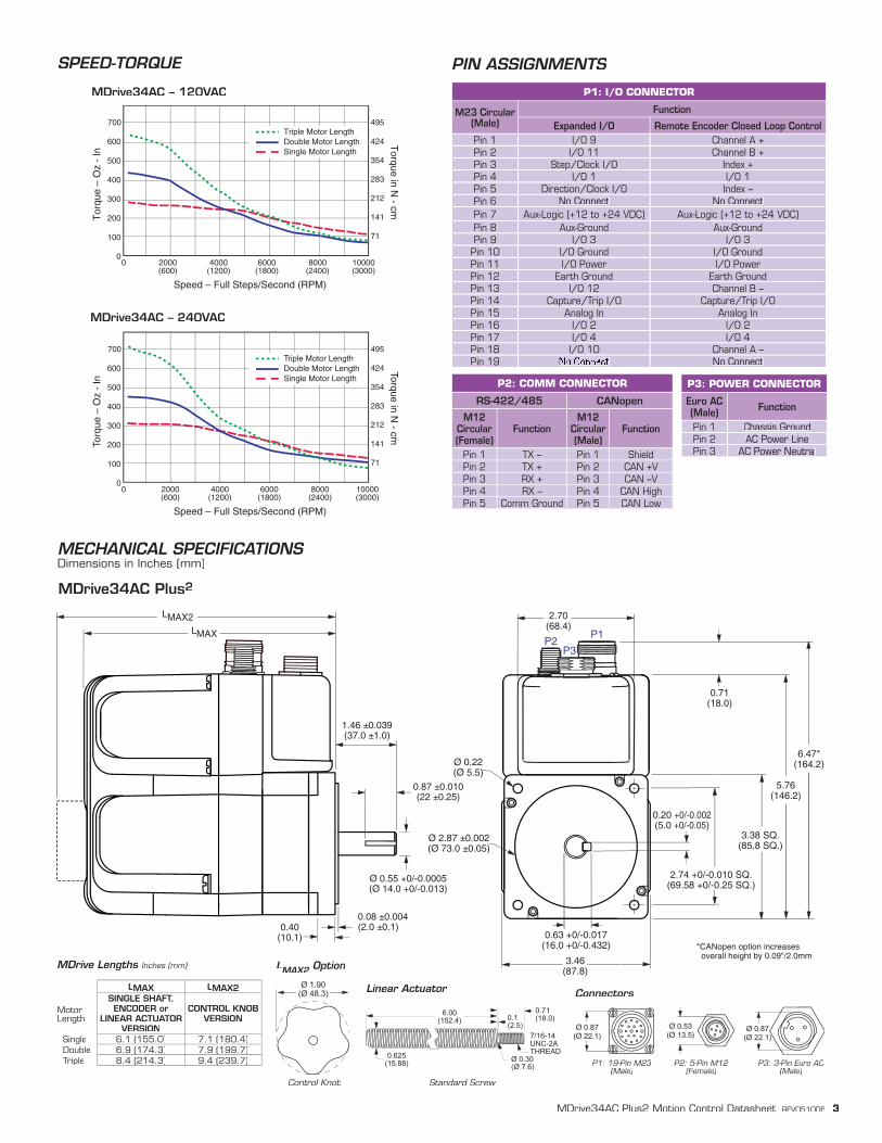
P3: POWER CONNECTOR
Euro AC (Male) Function
Pin 1 Chassis GroundPin 2 AC Power LinePin 3 AC Power Neutral
P1: I/O CONNECTOR
M23 Circular(Male)
Function
Expanded I/O Remote Encoder Closed Loop ControlPin 1 I/O 9 Channel A +Pin 2 I/O 11 Channel B +Pin 3 Step/Clock I/O Index +Pin 4 I/O 1 I/O 1Pin 5 Direction/Clock I/O Index –Pin 6 No Connect No ConnectPin 7 Aux-Logic (+12 to +24 VDC) Aux-Logic (+12 to +24 VDC)Pin 8 Aux-Ground Aux-GroundPin 9 I/O 3 I/O 3Pin 10 I/O Ground I/O GroundPin 11 I/O Power I/O PowerPin 12 Earth Ground Earth GroundPin 13 I/O 12 Channel B –Pin 14 Capture/Trip I/O Capture/Trip I/OPin 15 Analog In Analog InPin 16 I/O 2 I/O 2Pin 17 I/O 4 I/O 4Pin 18 I/O 10 Channel A –Pin 19 No Connect No Connect
P2: COMM CONNECTOR
RS-422/485 CANopen
M12 Circular (Female)
FunctionM12
Circular (Male)
Function
Pin 1 TX – Pin 1 ShieldPin 2 TX + Pin 2 CAN +VPin 3 RX + Pin 3 CAN –VPin 4 RX – Pin 4 CAN HighPin 5 Comm Ground Pin 5 CAN Low
2.70 (68.4)
Ø 0.22 (Ø 5.5)
0.63 +0/-0.017 (16.0 +0/-0.432)
0.20 +0/-0.002 (5.0 +0/-0.05)
5.76 (146.2)
6.47* (164.2)
3.46 (87.8)
Ø 2.87 ±0.002 (Ø 73.0 ±0.05)
0.71 (18.0)
3.38 SQ. (85.8 SQ.)
2.74 +0/-0.010 SQ. (69.58 +0/-0.25 SQ.)
*CANopen option increases overall height by 0.09"/2.0mm
P3P1
P2LMAX
Ø 0.55 +0/-0.0005 (Ø 14.0 +0/-0.013)
0.08 ±0.004 (2.0 ±0.1)0.40
(10.1)
0.87 ±0.010(22 ±0.25)
1.46 ±0.039 (37.0 ±1.0)
LMAX2
MECHANICAL SPECIFICATIONSDimensions in Inches (mm)
MDrive34AC Plus2
SPEED-TORQUE
MDrive34AC – 120VAC
MDrive34AC – 240VAC
LMAX2 OptionMAX2 OptionMAX2
��������������
Ø 0.53(Ø 13.5)
Ø 0.87(Ø 22.1)
Connectors
P2: 5-Pin M12(Female)
P1: 19-Pin M23(Male)
P3: 3-Pin Euro AC(Male)
��������������
PIN ASSIGNMENTS
���
���
���
���
���
���
����������������
�����������
�����
���
���
���
���
���
��
�������������������������������
� � ���������
� ����������
� ����������
�����������
� ����������
��
��� ������������������������������������������������������������
���
���
���
���
���
���
����������������
����������������
���
���
���
���
���
��
�������������������������������
� � ���������
� ����������
� ����������
�����������
� ����������
��
��� ������������������������������������������������������������
Standard Screw
Linear ActuatorLMAX LMAX2
Motor Length
SINGLE SHAFT, ENCODER or
LINEAR ACTUATOR VERSION
CONTROL KNOB VERSION
Single 6.1 (155.0) 7.1 (180.4)Double 6.9 (174.3) 7.9 (199.7)Triple 8.4 (214.3) 9.4 (239.7)
MDrive Lengths Inches (mm)
�������������������
������������
�����������
�������������
�����
�������������
Control Knob
ORDER INFORMATION – MDrive34AC Plus2 Motion Control2 Motion Control2
OPTIONS
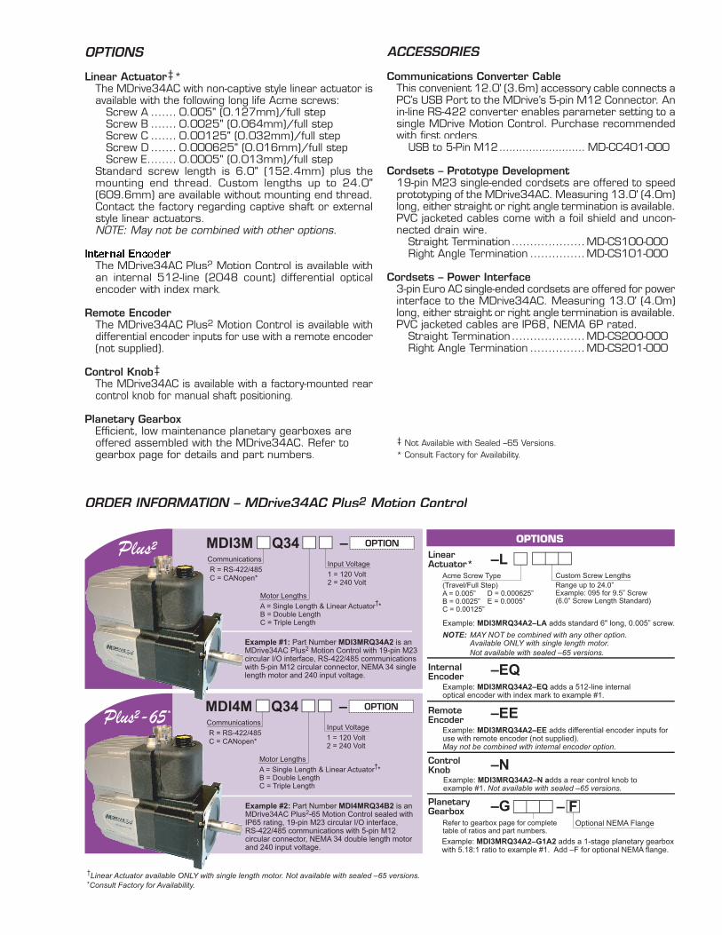
Linear Actuator‡* The MDrive34AC with non-captive style linear actuator is
available with the following long life Acme screws: Screw A ....... 0.005" (0.127mm)/full step Screw B ....... 0.0025" (0.064mm)/full step Screw C ....... 0.00125" (0.032mm)/full step Screw D ....... 0.000625" (0.016mm)/full step Screw E........ 0.0005" (0.013mm)/full step Standard screw length is 6.0" (152.4mm) plus the
mounting end thread. Custom lengths up to 24.0" (609.6mm) are available without mounting end thread. Contact the factory regarding captive shaft or external style linear actuators.
NOTE: May not be combined with other options.
Internal Encoder The MDrive34AC Plus2 Motion Control is available with
an internal 512-line (2048 count) differential optical encoder with in dex mark.
Remote Encoder The MDrive34AC Plus2 Motion Control is available with
differential encoder inputs for use with a remote encoder (not supplied).
Control Knob‡ The MDrive34AC is available with a factory-mounted rear
control knob for manual shaft positioning.
Planetary Gearbox Effi cient, low maintenance planetary gearboxes are
offered assembled with the MDrive34AC. Refer to gearbox page for details and part numbers.
ACCESSORIES
Communications Converter CableThis convenient 12.0' (3.6m) accessory cable connects a PC’s USB Port to the MDrive’s 5-pin M12 Connector. An in-line RS-422 con vert er enables parameter setting to a single MDrive Motion Control. Purchase recommended with fi rst orders. USB to 5-Pin M12 .......................... MD-CC401-000
Cordsets – Prototype Development19-pin M23 single-ended cordsets are offered to speed prototyping of the MDrive34AC. Measuring 13.0' (4.0m) long, either straight or right angle termination is available. PVC jacketed cables come with a foil shield and uncon-nected drain wire. Straight Termination ....................MD-CS100-000 Right Angle Termination ...............MD-CS101-000
Cordsets – Power Interface3-pin Euro AC single-ended cordsets are offered for power interface to the MDrive34AC. Measuring 13.0' (4.0m) long, either straight or right angle termination is available. PVC jacketed cables are IP68, NEMA 6P rated. Straight Termination ....................MD-CS200-000 Right Angle Termination ...............MD-CS201-000
‡ Not Available with Sealed –65 Versions.* Consult Factory for Availability.
��
����������������
�����������
����������������������������������������������������������������������������������������������������������������������������������������������������
������������������������������������������������������������������������������������������������������
������������������
�����������������������������������������������������������������������������������������������������������������������������
�������������������������������������������������������������������
�����
��������������������
�����
������������������
OPTIONS
�����������������������������������������������������������������������������������������������
������������������������������������������������������������
�������������������������������������������������� ����������������������������������������
� ���������������������������������������
�����������������
���������������������������������������������������
���������������
��������������������
������������������������������������������������������������������������
�����������������������������������������������������������������������������������������������������������������������������������
������������������������
������������������������
�������������
�������������������������������������
����������������������������������
���������������������������������������������������������������������������������������������������������������������������������������������������������������������������������������������������������������������������������
������
�������������
������������������������
��������������
��������������������������
����������
��������������������������������������������������������������������������������������������������������������������������������������������������������������������������������������������������������������������������������������������������������
������������������������
�������������
�������������������������������������
����������������������������������
������
�������������
������������������������
��������������
��������������������������

The MDrive34AC Plus2 is available with a Planetary Gearbox option developed to increase torque at lower speeds, enable better inertia matching and produce fi ner positional resolutions. These effi cient, low
MDRIVE34AC PLUS2MDRIVE34AC PLUS2MDRIVE34AC PLUS WITH PLANETARY GEARBOX2 WITH PLANETARY GEARBOX2
Planetary Gearbox for MDrive34AC Plus2
Dimensions in Inches (mm)
Permitted Output Torque
(oz-in/Nm)
Gearbox Effi ciency
Maximum Backlash
Output Side with Ball Bearing
Maximum Load(lb-force/N)
Weight(oz/g)
Radial Axial Gearbox with Flange
1-STAGE 2832/20.0 0.80 1.0° 90/400 18/80 64.4/1827 66.7/1890
2-STAGE 8496/60.0 0.75 1.5° 135/600 27/120 89.5/2538 92.6/2625
3-STAGE 16992/120.0 0.70 2.0° 225/1000 45/200 92.6/2625 118.5/3360
maintenance Planetary Gearbox come fully assembled with the MDrive and are offered in a large number of reduction ra-tios in 1-, 2- and 3-stage confi gurations. An optional NEMA Output Flange allows
Ratios and Part Numbers
Planetary Gearbox
Ratio(Rounded)
PartNumber
1-Stage 3.71:1 G1A11-Stage 5.18:1 G1A21-Stage 6.75:1 G1A3
2-Stage 13.73:1 G1A42-Stage 15.88:1 G1A52-Stage 18.37:1 G1A62-Stage 19.20:1 G1A72-Stage 22.21:1 G1A82-Stage 25.01:1 G1A92-Stage 26.85:1 G1B12-Stage 28.93:1 G1B22-Stage 34.98:1 G1B32-Stage 45.56:1 G1B4
3-Stage 50.89:1 G1B53-Stage 58.86:1 G1B63-Stage 68.07:1 G1B73-Stage 71.16:1 G1B83-Stage 78.72:1 G1B93-Stage 92.70:1 G1C13-Stage 95.18:1 G1C23-Stage 99.51:1 G1C33-Stage 107.21:1 G1C43-Stage 115.08:1 G1C53-Stage 123.98:1 G1C63-Stage 129.62:1 G1C73-Stage 139.14:1 G1C83-Stage 149.90:1 G1C93-Stage 168.85:1 G1D13-Stage 181.25:1 G1D23-Stage 195.27:1 G1D33-Stage 236.10:1 G1D43-Stage 307.55:1 G1D5
Planetary Gearbox Parameters
mounting the Planetary Gearbox to the load using a standard NEMA bolt circle. Planetary Gearbox may be combined with other MDrive34 options, however are unavailable with Linear Actuators.
Gearbox Lengths Inches (mm)
k1GEARBOX* with FLANGE†
1-Stage 4.315 (109.6) 4.433 (112.6)2-Stage 5.169 (131.3) 5.287 (134.3)3-Stage 6.024 (153.0) 6.142 (156.0)
�����������������������
���������������������
���������������������������������������������������������������������
������������
���������������
���������������
�����������
�������
��������
������������������������
����������������������
��
�������������������
������������������
������������������
������������������
������
������
������������
���������
����������
�������������������������������������������
��������������
������������
����������������������������������������������������������
����������
�����������
**Include optional planetary gearbox by adding –G plus 3 characters to the end of an MDrive part number.
**
370 N. Main StreetP.O. Box 457Marlborough, CT 06447 U.S.A.Phone: 860/295-6102Fax: 860/295-6107E-mail: [email protected]
TECHNICAL SUPPORTEastern U.S.A. Phone: 860/295-6102 Fax: 860/295-6107 E-mail: [email protected] U.S.A. Phone: 760/966-3162 Fax: 760/966-3165 E-mail: [email protected]/UK Phone: +49/7720/94138-0 Fax: +49/7720/94138-2 E-mail: [email protected]
U.S.A. SALES OFFICESEastern Region Phone: 862/208-9742 Fax: 973/661-1275 E-mail: [email protected] Region Phone: 260/402-6016 Fax: 419/858-0375 E-mail: [email protected] Region Phone: 408/472-1971 Fax: 408/268-0716 E-mail: [email protected]
IMS MOTORS DIVISION 105 Copperwood Way, Suite H Oceanside, CA 92054 Phone: 760/966-3162 Fax: 760/966-3165 E-mail: [email protected]
IMS EUROPE GmbH Hahnstrasse 10, VS-Schwenningen Germany D-78054 Phone: +49/7720/94138-0 Fax: +49/7720/94138-2 E-mail: [email protected] Sales Management 4 Quai Des Etroits 69005 Lyon, France Phone: +33/4 7256 5113 Fax: +33/4 7838 1537 E-mail: [email protected] Sales Phone: +49/35205/4587-8 Fax: +49/35205/4587-9 E-mail: [email protected]/UK Technical Support Phone: +49/7720/94138-0 Fax: +49/7720/94138-2 E-mail: [email protected]
IMS UK Ltd. 25 Barnes Wallis Road Segensworth East Fareham, Hampshire, UK PO155TT Phone: +44/1489/889-825 Fax: +44/1489/889-857 E-mail: [email protected]
IMS ASIA PACIFIC OFFICE 30 Raffl es Pl., 23-00 Caltex House Singapore 048622 Phone: +65/6233/6846 Fax: +65/6233/5044 E-mail: [email protected]
DISTRIBUTED BY:
© 2006 Intelligent Motion Systems, Inc. All Rights Reserved. REV051006IMS Product Disclaimer and most recent product information at www.imshome.com.
����������������������������������������������������www.imshome.com