Embed Size (px)
Citation preview

A
CNepsgs©
K
1
thpHapicckbui
NnT
0h
Available online at www.sciencedirect.com
ScienceDirect
Journal of the European Ceramic Society 34 (2014) 2823–2831
Evidence of optimal interfaces in bio-inspired ceramic-composite panels forsuperior ballistic protection
Stefano Signetti a, Nicola M. Pugno a,b,c,∗a Laboratory of Bio-Inspired and Graphene Nanomechanics, Department of Civil, Environmental and Mechanical Engineering, University of Trento,
Via Mesiano 77, I-38123 Trento, Italyb Centre for Materials and Microsystems, Fondazione Bruno Kessler, Via Sommarive 18, I-38123 Povo (Trento), Italy
c School of Engineering and Materials Science, Queen Mary University of London, Mile End Road, E1 4NS, London, UK
Received 15 November 2013; accepted 19 December 2013Available online 4 February 2014
bstract
eramic-composite panels are acknowledged to provide effective impact protection even against small fragments and armour piercing projectiles.ature shows similar solutions, coupling an hard face and soft backing layers, in dermal animal armours for protection against predators. Finite
lement simulations of impact on ceramic-composite panels, to evaluate their energy absorption capability, are presented. The influence of keyarameters, like interface strength and friction, on ballistic limit is studied. We find that a proper set of interface parameters is able to maximize the
pecific energy absorption of the panel: although this optimum is variable case by case depending on projectile penetrability and target configuration,eneral guidelines are provided. Oblique impact results in a higher ballistic limit also thanks to projectile change in trajectory, providing interestingpots for future developments. Numerical results are compared with experimental data from literature and forecasts of analytical models.2014 Elsevier Ltd. All rights reserved.
pact; F
Tpe
mtlahmih
eywords: Impact; Ceramic-composite panels; Energy absorption; Oblique im
. Introduction
Laminated composite materials are widely employed in pro-ective armours, automotive and aerospace applications: theseomogeneous panels have their weak point in small and highenetrating fragments and armour piercing (AP) projectiles.ard faced ceramics with a multilayered composite backing
re widely used in order to solve these problems, for exam-le, in protective body armours. On these heterogeneous plates,mpactors are first blunted and weared down by the exterior harderamic which also spreads the load over a larger area; then theomposite tough backing1–5 deforms and absorbs the residualinetic energy of the decelerated and damaged fragment; the
acking also delays and mitigates the initiation of tensile fail-re in the ceramic and it is capable to catch both ceramic andmpactor fragments, preventing them to constitute further injury.∗ Corresponding author at: Laboratory of Bio-Inspired and Grapheneanomechanics, Department of Civil, Environmental and Mechanical Engi-eering, University of Trento, Via Mesiano 77, I-38123 Trento, Italy.el.: +39 0461 282525; fax: +39 0461 282599.
E-mail address: [email protected] (N.M. Pugno).
(tapr(Tts
955-2219/$ – see front matter © 2014 Elsevier Ltd. All rights reserved.ttp://dx.doi.org/10.1016/j.jeurceramsoc.2013.12.039
inite element simulations
his solution can be found also in nature, for example in Ara-aima gigas dermal armour, whose scales are made up of anxternal hard mineral layer on a multilayered collagen backing.6
The optimum balance between lightness, thickness, perfor-ance, and economic requirements is a challenging engineering
ask. Ceramics are lighter with respect to traditional mono-ithic hard-steel panels, while comparable in stiffness, hardnessnd compressive strength. However, they are characterized by aigher density (about a factor of two) with respect to compositeaterials. Thus, their use has to be carefully balanced and limited
n lightweight applications like, for instance, spacecraft oruman body protection from micrometeorites and space debris.
Alumina (Al2O3), Boron Carbide (B4C) and Silicon CarbideSiC) are some of the most widely employed ceramics in the sec-or. For the backing, polyetilene- and aramid-based tough fibresre arranged in woven or unidirectional (UD) textiles within aolymer thermoplastic or thermoset matrix (epoxy or vinylesteresins): they can range from traditional ones, like Kevlar®
aramid), and more recent like Dyneema® (UHMWPE)7 or
waron® (aramid).8 The main advantage of composites is thathat their properties can be tailored on the requirements for apecific application. High specific strength, specific stiffness

2 ropea
acUsids
pmaott
V
waioosactc
cedsaetrIriem
tntuTiImdi
maLs
imtgtsttdp
wtJcivoh
hbwelmcfiphn
2
wepiRw
wfictatb
824 S. Signetti, N.M. Pugno / Journal of the Eu
nd toughness make them an obvious choice for aerospace vehi-les; the resistance against unkind environments (e.g. corrosive,V, extreme temperatures, etc.), enhances the robustness of the
tructure. A measure of the fibres performance against ballisticmpact was provided by Cunniff9 for flat targets hit by cylin-rical projectiles, and was defined as the product of the fibrespecific toughness by the strain wave velocity.
The design and the performance evaluation of compositeanels undergoing ballistic impact require the understanding ofaterial properties under high-velocity impact conditions. Recht
nd Ipson10 proposed a relatively simple analytical model, basedn energy conservation laws, able to determine ballistic curveso fit experimental results. In this model the final velocity Vf ofhe impactor is given, as a function of its initial velocity V0, by:
f = q(V
p0 − V
pB
)1/p(1)
here VB is the target ballistic limit, p a fitting parameter, usu-lly equal to 2 in case of rigid projectiles and target resistancendependent to impactor velocity, and q a coefficient dependingn model assumption (e.g.: q = 1 if assuming that dissipation isnly due to target deformation, and no projectile damage is con-idered). A comparison between experimental ballistic curvesnd Eq. (1) can be found in Ref. 11 showing that this modelan apply with a good level of approximation for the estima-ion of the final velocity, both for isotropic and heterogeneousomposite material.
Espinosa et al.12 investigated the response of multilayerederamic–steel targets under high-velocity impact through finitelement simulations. A multiple-plane microcracking model toescribe the inelastic constitutive behaviour of ceramics underevere damage was implemented into a finite element code. Theirnalyses showed that the penetration process is highly depend-nt on the multilayered configuration (stacking sequence) andhe target structural design (geometry and boundary conditions),ather than on the type and properties of the ceramic material.n addition the erosion parameter in simulations, to which theesidual damage strength is related, plays a key role in predict-ng the interaction of the penetrator in the target: thus, a coupledxperimental and numerical study is found to be necessary in aeaningful ceramic-composite armour design.Hetherington et al.13,14 developed an analytical model for
he analysis of two-component composite armours subjected toormal and oblique impact. They observed that, circular con-ours of constant deformation which occur in backing platesnder normal impact, tends to be elliptical for oblique strike.hey assumed that the projectile tip deforms into an ellipse as it
mpacts the front face of the ceramic under the oblique impact.t was found that an inclined ceramic composite armour plate isore effective, on a thickness basis, than one arranged perpen-
icular to the line of impact; parallel the ballistic limit velocityncreases with obliquity. This model is reported in Ref. 15.
Considering the cost related to the ceramic and composite
aterials used in ballistic experiments, the need for developingccurate predictive simulation tools becomes more important.arge simulation sensitivity campaigns would let the under-tanding of the influence of each considered parameter, leading
σ
wa
n Ceramic Society 34 (2014) 2823–2831
nto the design of the optimal solution that couples toughnessaximization and weigh reduction. Analytical modelling for
he evaluation of impact behaviour of composite targets16,22
enerally assumes the laminate resistance σ as a quadratic func-ion of the impactor istantaneous velocity V, taking into accounttrain rate effects, σ = σ (V, V2). Since the backing layers, dueo impactor deceleration, progressively face a lower velocity,he specific absorbed energy Eabs for each ply is expected toecrease as the number of layers N, i.e. the areal density of thelate, increases:
Eabs
N∝ Nα (2)
ith α < 0. However, this is usually in contrast with experimentalests which show that generally the exponent � can be positive.acobs and Van Dingenen23 showed how the scaling of Eq. (2)an invert from soft to hard (pressed) panel: however, in the studyt is not provided a formal explanation of the trend. The obser-ation of scalings of energy absorption and the understandingf related mechanisms could lead into optimized panels againstigh-strain and strain-rate loads.
Our study focuses on these trends in order to find if andow the failure mechanism of ceramic-composite panels coulde enhanced in order to maximize dissipation. The outcomesould be extensible in general to other typologies of multilay-
red structures. The effect of oblique impact on the ballisticimit is also studied. These scopes require advanced finite ele-ent models with proper material constitutive laws in order to
atch the real dynamics of impactor–armour interaction and tond effective ways of developing optimized solutions. This workresents a numerical model for ballistic impact simulations inybrid ceramic-fibre reinforced composite armours. The expliciton-linear finite element solver LS-DYNA®24,25 was used.
. Modelling of impact
Basing on an energetic approach for modelling impacts, asidely used in literature,16–23 the variation of projectile kinetic
nergy in penetrating the plate must balance the amount of dissi-ated energy (Eabs) in the damaged volume of the target, whichs assumed to be cylindrical and, defined by the projectile radius
and the plate thickness t. Thus, the following relation can beritten:
12mV 2
0 − 12mV 2
f = σπR2t (3)
here m is the mass of the projectile, V0 and Vf the initial andnal velocity of the impactor respectively and σ the ultimateompressive strength of the material. Assuming a rigid projec-ile, Eq. (3) yields Eq. (1) for q = 1 and p = 2. A more realisticpproach consists in considering the velocity as a quadratic func-ion of the istantaneous impact velocity V; for each layer it cane assumed:(
2 2)
= σ0 a0 + a1kV + a2k V (4)
here a0, a1, a2 are parameters depending on material behaviournd impactor geometry according to Ref. 21, σ0 is the material
ropean Ceramic Society 34 (2014) 2823–2831 2825
ctsstodvic
V
vimttca
tctowmef
wrFuwii
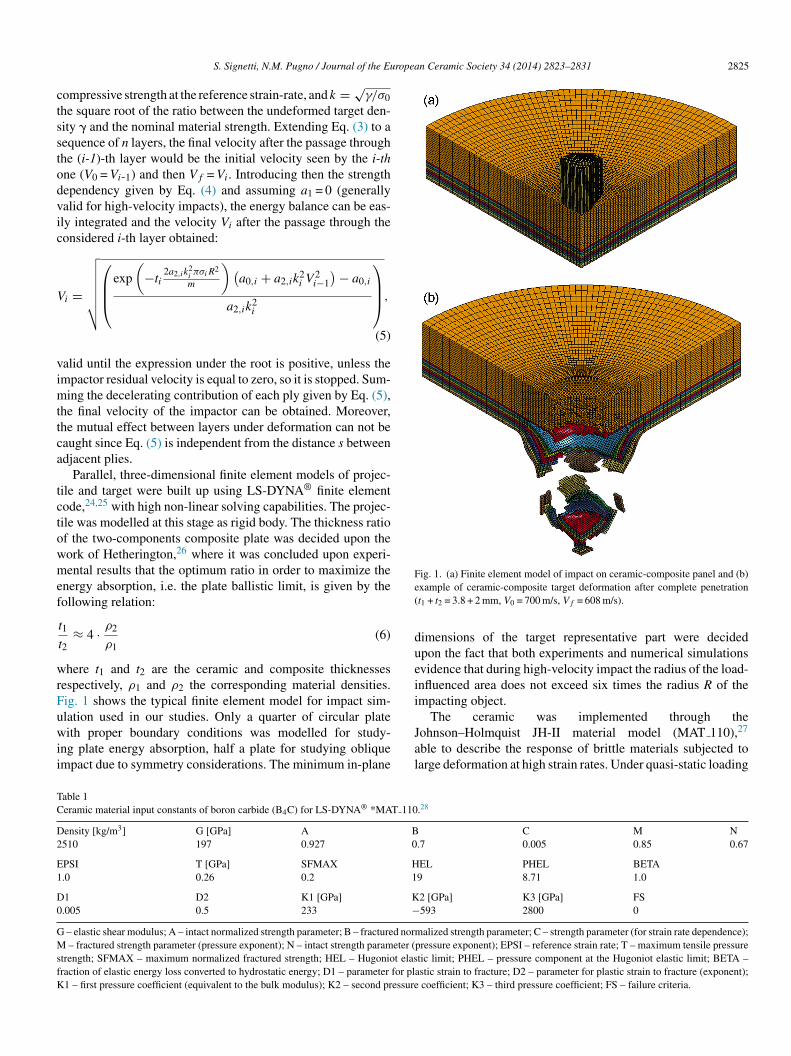
Fig. 1. (a) Finite element model of impact on ceramic-composite panel and (b)e(
dueii
TC
D2
E1
D0
GMsfK
S. Signetti, N.M. Pugno / Journal of the Eu
ompressive strength at the reference strain-rate, and k = √γ/σ0
he square root of the ratio between the undeformed target den-ity � and the nominal material strength. Extending Eq. (3) to aequence of n layers, the final velocity after the passage throughhe (i-1)-th layer would be the initial velocity seen by the i-thne (V0 = Vi-1) and then Vf = Vi. Introducing then the strengthependency given by Eq. (4) and assuming a1 = 0 (generallyalid for high-velocity impacts), the energy balance can be eas-ly integrated and the velocity Vi after the passage through theonsidered i-th layer obtained:
i =
√√√√√√√
⎛⎜⎜⎝
exp
(−ti
2a2,ik2iπσiR2
m
) (a0,i + a2,ik
2i V
2i−1
) − a0,i
a2,ik2i
⎞⎟⎟⎠,
(5)
alid until the expression under the root is positive, unless thempactor residual velocity is equal to zero, so it is stopped. Sum-
ing the decelerating contribution of each ply given by Eq. (5),he final velocity of the impactor can be obtained. Moreover,he mutual effect between layers under deformation can not beaught since Eq. (5) is independent from the distance s betweendjacent plies.
Parallel, three-dimensional finite element models of projec-ile and target were built up using LS-DYNA® finite elementode,24,25 with high non-linear solving capabilities. The projec-ile was modelled at this stage as rigid body. The thickness ratiof the two-components composite plate was decided upon theork of Hetherington,26 where it was concluded upon experi-ental results that the optimum ratio in order to maximize the
nergy absorption, i.e. the plate ballistic limit, is given by theollowing relation:
t1
t2≈ 4 · ρ2
ρ1(6)
here t1 and t2 are the ceramic and composite thicknessesespectively, ρ1 and ρ2 the corresponding material densities.ig. 1 shows the typical finite element model for impact sim-
lation used in our studies. Only a quarter of circular plateith proper boundary conditions was modelled for study-ng plate energy absorption, half a plate for studying obliquempact due to symmetry considerations. The minimum in-plane
Jal
able 1eramic material input constants of boron carbide (B4C) for LS-DYNA® *MAT 110
ensity [kg/m3] G [GPa] A B510 197 0.927 0
PSI T [GPa] SFMAX H.0 0.26 0.2 1
1 D2 K1 [GPa] K.005 0.5 233 −
– elastic shear modulus; A – intact normalized strength parameter; B – fractured norm – fractured strength parameter (pressure exponent); N – intact strength parameter (
trength; SFMAX – maximum normalized fractured strength; HEL – Hugoniot elasraction of elastic energy loss converted to hydrostatic energy; D1 – parameter for pla1 – first pressure coefficient (equivalent to the bulk modulus); K2 – second pressure
xample of ceramic-composite target deformation after complete penetrationt1 + t2 = 3.8 + 2 mm, V0 = 700 m/s, Vf = 608 m/s).
imensions of the target representative part were decidedpon the fact that both experiments and numerical simulationsvidence that during high-velocity impact the radius of the load-nfluenced area does not exceed six times the radius R of thempacting object.
The ceramic was implemented through the
ohnson–Holmquist JH-II material model (MAT 110),27ble to describe the response of brittle materials subjected toarge deformation at high strain rates. Under quasi-static loading
.28
C M N.7 0.005 0.85 0.67
EL PHEL BETA9 8.71 1.0
2 [GPa] K3 [GPa] FS593 2800 0
alized strength parameter; C – strength parameter (for strain rate dependence);pressure exponent); EPSI – reference strain rate; T – maximum tensile pressuretic limit; PHEL – pressure component at the Hugoniot elastic limit; BETA –stic strain to fracture; D2 – parameter for plastic strain to fracture (exponent);
coefficient; K3 – third pressure coefficient; FS – failure criteria.

2826 S. Signetti, N.M. Pugno / Journal of the European Ceramic Society 34 (2014) 2823–2831
Table 2Kevlar-epoxy composite backing properties for LS-DYNA® *MAT 58. For the detailed meaning of each parameter, see Ref. 25.
KEVLAR
Density [kg/m3] EA [GPa] EB [GPa] EC [GPa] PRBA TAU1 [GPa] GAMMA12130 164 164 18 0.0 0.0 0.0
GAB [GPa] GBC [GPa] GCA [GPa] SLIMT1 SLIMC1 SLIMT2 SLIMC218 18 18 0.05 0.50 0.05 0.50
E11C E11T E22C E22T GMS0.35 0.1 0.35 0.1 0.25
XC [GPa] XT [GPa] YC [GPa] YT [GPa] SC [GPa]0.950 0.500 0.950 0.500 0.200
EPOXY RESIN
Density [kg/m3] EA [GPa] EB [GPa] EC [GPa] PRBA TAU1 [GPa] GAMMA1900 0.5 0.5 0.5 0.34 0.0 0.0
GAB [GPa] GBC [GPa] GCA [GPa] SLIMT1 SLIMC1 SLIMT2 SLIMC20.187 0.187 0.187 0.5 0.5 0.5 0.5
E11C E11T E22C E22T GMS0.350 0.05 0.350 0.05 0.025
XC [GPa] XT [GPa] YC [GPa] YT [GPa] SC [GPa]0.400 0.02 0.400 0.02 0.0075
EA – Young’s modulus in longitudinal direction (A); EB – Young’s modulus in transverse direction (B); EC – Young’s modulus in normal direction (C); PRBA –Poisson’s ratio; TAU1 – stress limit for the non-linear part of shear stress vs. shear strain curve; GAMMA1 – strain limit for the non-linear part of shear stress vs.shear strain curve; GAB – shear modulus in AB plane; GBC – shear modulus in BC plane; GCA – shear modulus in CA plane; SLIMT1 – stress limit factor after thestress maximum (fibre tension); SLIMC1 – stress limit factor after the stress maximum (fibre compression); SLIMT2 – stress limit factor after the stress maximum(matrix tension); SLIMC2 – stress limit factor after the stress maximum (matrix compression); E11C – strain at longitudinal compressive strength; E11T – strain atl ; E22l svers
chisnpsc
il
me
Fa
ongitudinal tensile strength; E22C – strain at transversal compressive strengthongitudinal compressive strength; XT – longitudinal tensile strength; YC – tran
onditions ceramics may be assumed as elastic-brittle materials;owever, when high strain rates are involved (like in ballisticmpacts) the post-yield response of the ceramic becomesignificant in evaluating its behaviour and then may have nonegligible influence on ballistic limit. The model allows for
rogressive damage, taking into account residual materialtrength and compressive bulking. The ceramic component wasonstituted in our case by boron carbide (B4C): in Table 1 thebs(
0
5
10
15
20
25
0.00 0.0 1 0.02
Time (m
En
erg
y (J
)
ig. 2. Energy balance of one of the performed simulations. The sum of internal, conbsorbed at each time by the plate (Eabs). The values refer to the quartered model.
T – strain at transversal tensile strength; GMS – strain at shear strength; XC –al compressive strength; YT – transversal tensile strength; SC – shear strength.
nput material constant are reported; these were available initerature28 and calibrated through experimental tests.
For the Kevlar® composite backing (Table 2), an orthotropicaterial model (MAT 58) was used, which implements a linear-
lastic branch followed by a non-linear post peak softening
ehaviour: the residual strength in compression, tension andhear can be defined as a fraction of the maximum material stressdefined by the SLIM factors). The equations which define the0.03 0.0 4 0.05
s)
Hourglass energyInternal energyKinetic energyContact energyTotal energy
E abs
tact (sliding interface) and hourglass energies represents the amount of energy

S. Signetti, N.M. Pugno / Journal of the European Ceramic Society 34 (2014) 2823–2831 2827
e s. T
fhtdpotsl
e
mpbaia
Fvad
Fig. 3. Residual velocity variation with the interlayer distanc
ailure criteria are presented in detail in the paper by Schweizer-of et al.29 The composite material model was implemented inhe layered thick shell (TSHELL) element, coupled with a userefined integration rule. This method, more refined than sim-ly using the smeared properties of the ply obtained by a rulef mixture, assigns to each through-thickness integration pointhe corresponding material (fibre or matrix) properties and con-titutive behaviour according to the volumetric fraction of the
aminate.The ceramic target and impacting fragment were mod-lled with under-integrated solid elements. Hourglass (spurious
3
r
1.00
0.80
0.60
0.40
0.20
0.00
0.0
-0.15-0.13-0.11-0.09-0.07-0.05-0.03-0.010.010.030.050.070.090.110.130.15
α
NFLS /σ
ig. 4. Influence of delamination strength parameters on specific energy absorption
elocity and shape. The interface normal failure stress (NFLS) and shear failure stress
rises when both parameters reach approximately one half of laminate peak stress. Tissipation by volume, Eabs = σπR2t ⇒ α ≤ 0).
he dashed line represents the output value given by Eq. (5).
ode) control was set. The energy balance of one of theerformed simulations (Fig. 2) confirms the effectiveness of theuilt model, as regards contact modelling, material behaviour,nd element performance. Hourglass (spurious modes) energys within the 15% of total internal energy, value that is generallycknowledged for not affecting overall response of the system.
. Energy absorption under ballistic impact
To first understand the role that layer interaction plays in theesistance mechanism under ballistic impact, several target with
0
0.20
0.40
0.60
0.80
1.00
SFLS /σ
0.13-0.15
0.11-0.13
0.09-0.11
0.07-0.09
0.05-0.07
0.03-0.05
0.01-0.03
-0.01-0.01
-0.03--0.01
-0.05--0.03
-0.07--0.05
-0.09--0.07
-0.11--0.09
-0.13--0.11
-0.15--0.13
(α exponent), for given inter-laminar friction (μS = 0.15, μD = 0.12), impactor(SFLS) are normalized with respect to single ply resistance σ. The best responseoo high values of these quantities provide “punch shear” failure (i.e. tends to

2828 S. Signetti, N.M. Pugno / Journal of the European Ceramic Society 34 (2014) 2823–2831
1.000.80
0.600.40
0.20
0.00
0.00
0.20
0.40
0.60
0.80
1.00-0.03-0.02-0.010.000.01
0.02
0.03
0.04
0.05
0.06
0.07
0.08
α
μDμS
0.07-0.08
0.06-0.07
0.05-0.06
0.04-0.05
0.03-0.04
0.02-0.03
0.01-0.02
0-0.01
-0.01-0
-0.02--0.01
-0.03--0.02
nt of f
eiispptpdw
FTf
etiSap
Fig. 5. Influence of the static (μS) and dynamic (μD) coefficie
quity of materials and stacking sequence but different distancen between the layer were performed; in this way, any differencen the behaviour is a function of the mere stacking distance s,et up for each configuration as a multiple of the each compositely thickness. In Fig. 3 the variation of residual velocity afterenetration with the distance between layers is shown. The dis-ance s is normalized with respect to the thickness t of the single
ly, assumed to be the same for all layers. The absorbed energyecreases as the distance between layer increases, showing thathen layers are packed together they are able to work in synergyig. 6. Scheme of oblique impact configuration on ceramic-composite armour.he damaged zone defined by θ and the possible deviation of the projectile δ
rom the initial obliquity β are shown.
luIb(eidotTemIf
fviotmt“cai
riction on the scaling exponent � of specific absorbed energy.
nhancing performances: when the distance between the layersends to be significant (almost over 10 times t), there is saturationn the trend of residual velocity (and so of the absorbed energy).ince the impactor is modelled as rigid body, the decrement ofbsorbed energy means a decrease in the internal energy of thelate.
Since the stacking distance between ceramic and compositeayers is seen to be important for overall deformation behaviournder impact, the effect of interface parameter was then studied.n fact, the discrepancy between the energy absorption providedy the energy based analytical model and experimental resultssee as example Ref. 23) is intuitively imputable to all thoseffects that are not considered in the energy balance: the mostmportant are delamination and mechanical interaction betweeneforming layers. A campaign of simulation was performed inrder to assess the influence on interface parameter on overallarget behaviour and then on the amount of dissipated energy.he main parameters of interest which define adhesive prop-rty are, for the specific contact algorithm implemented in theodel: the normal failure stress (NFLS, correlable with Mode
crack opening), the shear failure stress (SFLS, Mode II), andriction.
Fig. 4 shows the dependence of the α exponent to inter-ace strength parameters, with equity of impactor characteristics,elocity and interlaminar friction. An optimum is found. Start-ng from null interlaminar resistance, both in the in-plane andut-of-plane directions, the increase in delamination strength lethe layers to work better. Beyond a certain value, depending on
aterial stiffness, on the stiffness ratio between layers and onhe impactor energy and penetrability, the failure mode tends topunch shear” collapse and the α exponent decreases again and
an return negative. The trend is slightly more sensitive to sheardhesive strength. It must be underlined that the failure modes extremely dependent on the impactor velocity: punch shear
S. Signetti, N.M. Pugno / Journal of the European Ceramic Society 34 (2014) 2823–2831 2829
F le impe
ftstab
smissimtmbs
4
fiibiltptaH
ig. 7. Back view of the ceramic-composite panel with visualization of projectilliptical imprint; (b) normal impact with circular imprint.
ailure may occur also for low values of interface strength whenhe impactor is characterized by high penetrability; thus, thecaling depends also on impactor geometry and velocity. Givenhat, an optimum value can be determined with equity of bound-ry conditions and the solution that maximize absorption shoulde evaluated case by case.
Fig. 5 shows the results for the same analysis on the value oftatic (μS) and dynamic (μD) coefficient of friction: the perfor-ance increases with the increase of the two coefficients. The
nfluence is lower than interface parameter, mostly for two rea-ons: first, friction arises only after that delamination occurs;econd, it plays a role only for the sliding component of thenterface displacements. Friction mainly arises from surface
orphology. Since the morphology affects in some measure also
he interface strength and given the uncertainty in the experi-ental measuring of these friction coefficients, friction coulde considered in some way a minor amount of contribute to thehear interface strength, and its effect neglected.
tc
E
rint through contour of normal displacement: (a) oblique impact (β = 60◦) with
. Oblique impact
Simulations of 15◦, 30◦, 45◦, 60◦ oblique impact were per-ormed and compared with normal impactor incidence. Thenitial velocity of the impactor, for all cases, is 700 m/s. Thempactor is assumed at this stage to be rigid. In general, theallistic limit of the target tends to increase with the increasen angle of obliquity, since, from geometrical consideration theength of the impactor path within the target would be greater inhe case of oblique impact (Fig. 6). In case of inclined target therojectile imprint on the plate tends to be elliptical with one ofhe two axes that increase its length with the projectile obliquity,s also confirmed by our numerical simulations (Fig. 7). Frometeringhton and Rajagopalan30, the expression that defines for
he i-th layer the amount of the absorbed energy in the Eq. (3)
an be updated, for geometric considerations, as follows:abs(β; θ) = σiπciditi (7)

2830 S. Signetti, N.M. Pugno / Journal of the European Ceramic Society 34 (2014) 2823–2831
0.0
0.5
1.0
1.5
2.0
2.5
3.0
3.5
4.0
4.5
5.0
5.5
6.0
0 10 20 30 40 50 60 70 80
β (°)
Eabs/E
abs,0
Analytical solution
Numerical simulations
F β. Eni the at
wdd
c
d
aniittebt
te
aTiainFificesgo
Fd
ig. 8. Variation of panel energy absorption with the angle of impact incidence
mpact(Eabs,0). Numerical simulations results are compared with the ones fromhe cone θ = 45◦.
here β is the incidence angle of the impactor, θ is the angle ofiffusion of deformation after impact according to Fig. 7, ci andi the axes of the imprint ellipse given for each layer by (Fig. 7):
i = R
cos β+
n∑i=1
ti tan θ (8.a)
i = R +n∑
i=1
ti tan θ (8.b)
Fig. 8 shows the variation of absorbed energy with differentngle of incidence, and θ assumed to be 45◦. The values areormalized with respect to the energy absorbed under normalmpact condition. The results from numerical simulations aren good agreement with the analytical model, although the lat-er is based on very simple hypotheses. The difference seems
o slightly increase with the angle of incidence, and this can bexplained by the fact that with the increase of obliquity the realehaviour tends to diverge with respect to the geometric assump-ions of the conoid formation. We underline the similarity withaoc
-20
-18
-16
-14
-12
-10
-8
-6
-4
-2
00 10 20 30 4
β
δ (
°)
ig. 9. Variation of projectile obliquity δ with the initial angle of impact incidence β. Tirection, enhancing its penetrability.
ergy values are normalized with respect to the absorbed value in case of normalnalytical relation proposed by Hetherington,13 assuming the opening angle of
rend provided in Iqbal et al.31 which performed simulations andxperiments on metallic targets.
Another important aspect in oblique impact is the projectilexis obliquity variation with respect to its original configuration.his is a direct consequence of the non-symmetry given by the
nitial incidence itself. Depending both on the nature of the targetnd the shape of the projectile, this variation can be positive, i.e.ncreases original obliquity (measured as the angle between theormal to the target and the projectile axis, Fig. 7), or negative.ig. 9 shows the trend of the obliquity variation in relation to the
nitial inclination of the trajectory: the numerical spots can betted with a quadratic function and the obtained results can beorrelated with the analytical previsions provided in Rajagopalt al.32 for solely composite targets. Notice that for the specificet of simulations performed, in particular for the used impactoreometry and the specific plate stacking sequence, the variationf obliquity is negative: the projectile, instead of being driven
nd incorporated in the thickness, assuring a further mechanismf protection, is accommodated to the backing. This behaviouran be explained both with the specific target material behaviour0 50 60 70 80
(°)
he negative sign of δ means that the impactor tends to realign along the normal

ropea
uptomsTptp
5
ndatltebdtpbstnamtiffcpd
A
Snr2E
R
1
1
1
1
1
1
1
1
1
1
2
2
2
2
2
2
2
2
2
2
3
S. Signetti, N.M. Pugno / Journal of the Eu
nder high-strain compressive loads and the peculiar shape of therojectile faces, which helps the penetration instead of drivinghe impactor within layers. This suggests further investigationn how these can affect the sign of variation of obliquity, whicheans to discriminate between a high perforating striker or not,
imply by changing the layer stack-up or the projectile shape.he combined effect of target obliquity and projectile shape aserformed in Iqbal et al.30 for thin steel targets will be extendedo composite and ceramic-composite targets in a subsequentaper.
. Conclusions
Finite element models of ceramic-composite panels underormal and oblique impact were developed. Our computationsemonstrate good agreement with existing experimental datand the prevision of analytical models: thus, we can concludehat these simulations can be used for an improved design ofightweight ceramic-composite protective panels. We showedhat the energy absorption of the plate can be maximized forach configuration by setting proper interface parameter: theest behaviour is not given simply by the case of maximumelamination area but from the combination of material frac-ure, dissipation through deformation of the plate apart from therojectile imprint, and vibrations. Since the impactor penetra-ility (related to its velocity, geometry, and mass), the laminatetacking sequence, and the material constitutive law can affecthe overall response, general values of these parameters can-ot be provided. However, numerical simulations configure as
powerful tool to gain case by case the absorption optimum,aximizing the contribution in adding further layers, saving
hen in weight. Finally, oblique impact was observed to causenteresting effect on variation of striker obliquity, suggestingurther investigation on this direction, in order to understand,or example, the best arrangement of ceramic and compositeomponents, the worst shape condition in terms of projectileenetration, and to explain the optimized structure of naturalermal armour.
cknowledgments
NMP is supported by the European Research Council (ERCtG Ideas 2011 BIHSNAM on “Bio-Inspired hierarchical super-anomaterials”, ERC PoC 2013-1 REPLICA2 on “Large-areaeplication of biological anti-adhesive nanosurfaces”, ERC PoC013-2 KNOTOUGH on “Super-tough knotted fibres”) anduropean Commission under Graphene Flagship.
eferences
1. Pugno NM. Mimicking nacre with super-nanotubes for producing optimizedsuper-composites. Nanotechnology 2006;17:5480–4.
2. Pugno NM. Graded cross-links for stronger nanomaterials – Insight. MaterToday 2010;13:40–3.
3. Tan PH, Han WP, Zhao WJ, Wu ZH, Chang K, Wang H, et al. The shearmode of multi-layer graphene. Nat Mater 2012;11:294–300.
3
3
n Ceramic Society 34 (2014) 2823–2831 2831
4. Pugno NM. The egg of Columbus for making the world’s toughest fibres;2013 (available at arXiv:1304.6658).
5. Simple trick turns commercial polymer into world’s toughest fiber. MITTechnology Review; May/June 2013.
6. Yang W, Chen IH, Gludovatz B, Zimmermann EA, Ritchie RO, Meyers MA.Natural flexible dermal armor. Adv Mater 2013;25:31–48.
7. DSM Dyneema; 2013. http://www.dyneema.com8. TEIJIN Aramid; 2013. http://www.teijinaramid.com/aramids/twaron/9. Cunniff PM. Dimensionless parameters for optimization of textile-based
body armor systems. In: Proceedings of the 18th international symposiumon ballistics. 1999. p. 1303–10.
0. Recht RF, Ipson TW. Ballistic perforation dynamics. J Appl Mech1963;30(3):384–90.
1. Abrate S. Ballistic Impact on Composites. In: 16th international conferenceon composite materials. 2007.
2. Espinosa HD, Dwivedi S, Zavatteri PD, Yuan G. A numerical investigationof penetration in multilayered material/structure system. Int J Solids Struct1997;35(22):2975–3001.
3. Hetherington JG, Lemieux PF. The effect of obliquity on the ballisticperformance of two component composite armours. Int J Impact Eng1994;15:133–7.
4. Sadanandan S, Hetherington JG. Characterisation of ceramic/steel andceramic/aluminium armours subjected to oblique impact. Int J Impact Eng1997;19:811–9.
5. Abrate S. Impact on composite structures. Cambridge, UK: CambridgeUniversity Press; 1998.
6. Abrate S. Modeling of impacts on composite structures. Compos Struct2001;51:129–38.
7. Abrate S. Impact engineering of composite structures, CISM courses andlectures, vol. 526. New York: Springer Wien; 2011.
8. Goldsmith W. Impact – the theory and phisical behaviour of colliding solids.Mineola, New York: Dover; 2001.
9. Ben-Dour G, Dubinsky A, Elperin T. High-Speed penetration modeling andshape optimization of the projectile penetrating. Mech Based Des Struct2009;37:538–49.
0. Banichuk NV, Ivanova SY, Makeyev YV. On penetration of rigid non-axisymmetric bodies into elastic-plastic medium. Probl Strength Plast2010;70:131–9.
1. Forrestal MJ, Altman BS, Cargile JD, Hanchak SJ. An empirical equationfor penetration depth of ogive-nose projectiles into concrete targets. Int JImpact Eng 1994;15:395–405.
2. Forrestal MJ, Tzou DY. A spherical cavity-expansion penetration model forconcrete targets. Int J Solids Struct 1997;34:4127–46.
3. Jacobs MJL, Van Dingenen JLJ. Ballistic protection mechanisms in personalarmour. J Mater Sci 2001;36(3127):3142.
4. Hallquist JO. LS-DYNA theory manual. Livermore: Livermore SoftwareTechnology Corporation; 2006.
5. Hallquist JO. LS-DYNA keyword user’s manual. Livermore: Livermore Soft-ware Technology Corporation; 2006.
6. Hetherington JG. The optimization of two components composite armours.Int J Impact Eng 1992;12:409–14.
7. Cronin DS, Bui K, Kauffmann C, McIntosh G, Berstad T. Implementationand validation of the Johnson–Holmquist ceramic material model in Ls-Dyna. In: 4th European LS-DYNA users conference. 2003.
8. Johnson GR, Holmquist TJ. Response of boron carbide subjected tolarge strain, high strain rates, and high pressures. JPN J Appl Phys1999;85(12):8060.
9. Schweizerhof K, Weimar K, Munz T, Rottner T. Crashworthiness Analy-sis with Enhanced Composite Material Models in LS-DYNA, Merits andLimits. In: LS-DYNA world conference. 1996.
0. Hetherington JG, Rajagopalan BP. Investigation into the energy absorbedduring ballistic perforation of composite armours. Int J Impact Eng1994;11(1):33–40.
1. Iqbal MA, Diwakar A, Rayput A, Gupta NK. Influence of projectile shape
and incidence angle on the ballistic limit and failure mechanism of thickshell plates. Theor Appl Fract Mech 2012;62:40–53.2. Rajagopal A, Naik NK. Oblique ballistic impact behaviour of composites.Int J Damage Mech 2013;0(0):1–29.


![A High‐Throughput Search for Functionally Stable ... · (LFPO), form unstable interfaces with most solid electrolytes, particularly the high performance ceramic sulfides.[21–23]](https://img.dokumen.tips/doc/110x75/5f738e0695797216be0c6ad6/a-highathroughput-search-for-functionally-stable-lfpo-form-unstable-interfaces.jpg)


![University of Groningen METAL-CERAMIC INTERFACES ...Downloaded By: [Dutch Library Consortium (UKB) - Dekker Titles only] At: 10:58 3 March 2011](https://img.dokumen.tips/doc/110x75/6066139b9b8e370def1cbe09/university-of-groningen-metal-ceramic-interfaces-downloaded-by-dutch-library.jpg)