Embed Size (px)
Citation preview

Everything you ever wanted to knowabout Pembroke Power Station


1
ContentsWelcome to Pembroke 2
Our Station Values 3
Health & Safety 4
Station Overview 5
Data Sheet 5
The History of Pembroke 6
Pembroke A Power Station 6
Pembroke B Power Station 6
A Timeline of Our History 7
Combined Cycle Gas Turbines 8
Gas Supply 10
Gas Turbine 10
Heat Recovery Steam Generator 11
Steam Turbine 11
Condenser 11
Water Treatment 11
Turbo-Generator & Step-up Transformer 11
National Grid Substation 11
The Environment 12
Plant Design 12
Biodiversity at Pembroke 12
The Role of CCGTs 14
Plant Capability 15
Plant Operation 15
The Local Community 16
Join the Team! 17

2
Welcome to PembrokeThis brochure provides a summary of who we are and what we do here at Pembroke Power Station. If you have any questionsplease do not hesitate to ask a member of our team for further information.
RWE Generation UK
RWE is one of Europe’s leading electricity and gas companies.Through our expertise in oil, gas and lignite production;electricity generation from gas, coal, nuclear and renewables;energy trading as well as electricity and gas distribution andsales; we are active at all stages of the energy value chain.
In the UK our generating fleet is predominantly made up ofcombined cycle gas turbine (CCGT) power stations.
Our Power Station
Pembroke Power Station is a 2200MW CCGT power station whichofficially opened in 2012. Pembroke Power Station burns naturalgas and is capable of meeting the electricity demands of 3.5million homes. Our five 440MW CCGTs have a thermal efficiencyof around 60% making Pembroke one of the most efficient CCGTpower stations in Europe.
Who We Are
At Pembroke we employ a close-knit team of around 100 highly-skilled people. Our team can be divided into four departmentswho work closely together in order to keep the lights on:
EngineeringMechanical (Rotating Plant & Balance of Plant), Electrical,Controls & Instrumentation and DCS.
RegulationsEnvironment, Safety, Chemistry, Performance, Commercial,Learning & Development and Business Support.
OperationsMade up of 5 shift teams (A-E). Each team has five Operators andone Shift Team Leader.
MaintenanceMechanical, Electrical and Controls & InstrumentationTechnicians and Craft Teams.

3
DECISIVENESS
INTEG ITY HUMOUR
LOY LTY
R SPECT
RIVE
CHALLENGE
R SPONSIBILITY
COMMI MENT
OU
A
E
PERSEVERANCE
RUS
DEDICATI
N
ONESTY
Our Station ValuesOur station values represent the qualities and characteristics weexpect from every member of our team here at Pembroke. Thevalues were established to act as a guide in selecting our teamduring the initial recruitment process in 2010. Our aim was - andremains today - to recruit competent and talented individuals.Whilst we put great value on the technical competency of anindividual - we also look for individuals who we feel align withour values and culture at the station. Through a day-longinterview process involving technical interviews, group problemsolving, presentations and testing we observe and measure the‘whole’ person. By approaching our selection process with ourvalues at its centre, we continue to build a highly-performing andmotivated team and aspire to create a great place to work.
A local stonemason was commissioned to carve our stationvalues into rocks that were excavated from the old power station.These pieces of our station history are found along the walkwayto our office buildings, providing daily inspiration as we walk intowork each day.

4
Like most major industrial sites, hazards such as high pressures,temperatures and voltages are all present at Pembroke PowerStation. Our team of engineers and operators as well as oursophisticated control systems ensure that the process operatessafely, but some hazards will always remain. It is imperative thatHealth & Safety is taken seriously to ensure that everyone getshome safely at the end of the working day.
We employ a common-sense practical approach to Health & Safety at Pembroke. Our staff are encouraged to be pro-active and to test our procedures in the interests of Health & Safety. Everyone on site is empowered to challenge unsafeworking practices.
Our Health & Safety culture is centred very much around ourpeople. Protecting them from ill health and harm is an integralpart of what we do. We are all responsible for not just our ownpersonal safety, but also the safety of each other and our
Health & Safety We aim to sustain a culture where Health & Safety is embedded in the behaviours andactivities of everyone on site.
working environment. We work closely with our contractors andsite visitors, enabling them to take an active role in makingPembroke a safe site.

5
Station Overview
Data Sheet
Design output XL-mode (m-mode) 440MW (452MW)
per unit
Firing temperature XL-mode (m-mode) 12950C (1315
0C)
Stack height 75m
Shaft rotational speed (frequency) 3000rpm (50Hz)
Gas Turbine Exhaust Temperature 650
0C
Gross efficiency ~60%
Natural gas requirement 8,000,00
0m3/day
Total length of pipework 80km

The History of PembrokePembroke A Power Station
Pembroke A Power Station was an oil-fired power stationoperated by the Central Electricity Generating Board.Construction of the station, comprised of four 500MW units,began in 1965, with the station officially opening for generationin 1968. At 2000MW, it was one of the largest oil-fired powerstations in Europe. The station operated for almost 30 years andemployed as many as 400 people at its peak, before closing in1997. Demolition of the station was completed by 2003.
Pembroke B Power Station
Pembroke Power Station is a 2200MW combined cycle gasturbine (CCGT) power station which officially opened in 2012.Built on the site of the former CEGB oil-fired power station,Pembroke Power Station is capable of meeting the electricitydemands of 3.5 million homes.
The prospect of building a gas-fired power station on the site wasfirst discussed after planning permission was granted for theconstruction of two LNG terminals on the Milford Havenwaterway. The LNG terminals brought to the area a high pressuregas pipeline which could support the power station. The site wasfavourable due to the nearby access to a natural gas supply, itscoastal location allowed for direct cooling to maximise plantefficiency, whilst the existing 400kV substation provided accessto the National Grid.
In 2005, a planning application was submitted for theconstruction of a direct-cooled power station on the site of theformer CEGB station. The necessary environmental impactassessments and environmental permit applications weresubsequently launched. An abstraction license for the directcooling water was granted in December 2008 and planningpermission for the power station was granted in February 2009.Construction commenced in April 2009 and the environmentalpermit was agreed in November 2011, allowing for the plant tooperate. Plant commissioning took place in late 2011, withstation handover completed by September 2012.
Pembroke Facts
Pembroke Power Station issupplied by a 4.5 kilometre gaspipeline from across the Haven.At the time of construction the3005 metre-long section underthe estuary was the world’slongest ever horizontal drill.
6

7
Oil-fired ‘A’ Station construction
‘A’ Station demolished, 2000-2003
Opportunity identified
Abstraction licence granted December 2008
Station handover, September 2012
1st Unit handover, May 2012
Gas pipeline drilling
‘A’ Station in operation, 1968-1997
Planning permission for two LNG import terminals granted
Planning application submitted
Construction begins April 2009
Planning permission granted January 2009
100% staff on site, Q4 2011
Commissioning, Q3 2011
A Timeline of Our History2015
2012
2010
2011
2008
2004
1997
1965
2009
2005
2003
1968
MXL upgrade, April-December 2015
8
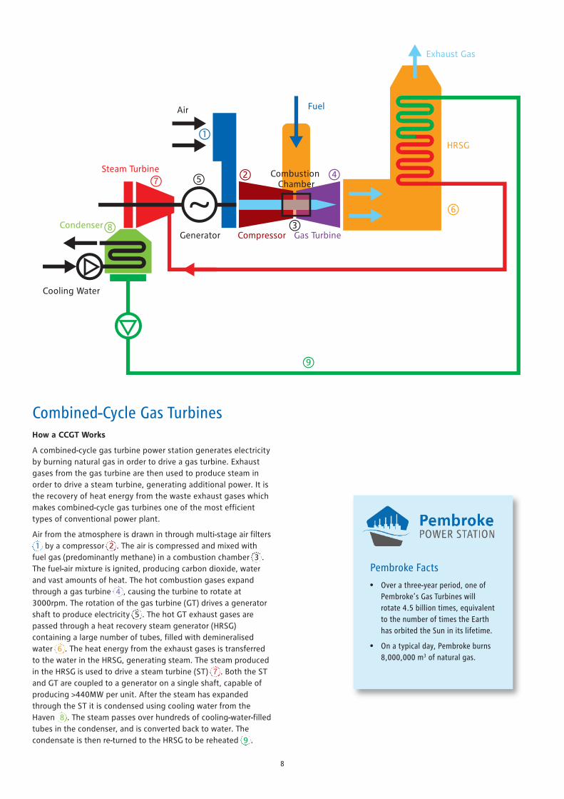
Combined-Cycle Gas TurbinesHow a CCGT Works
A combined-cycle gas turbine power station generates electricityby burning natural gas in order to drive a gas turbine. Exhaustgases from the gas turbine are then used to produce steam inorder to drive a steam turbine, generating additional power. It isthe recovery of heat energy from the waste exhaust gases whichmakes combined-cycle gas turbines one of the most efficienttypes of conventional power plant.
Air from the atmosphere is drawn in through multi-stage air filters(1) by a compressor (2). The air is compressed and mixed withfuel gas (predominantly methane) in a combustion chamber (3).The fuel-air mixture is ignited, producing carbon dioxide, waterand vast amounts of heat. The hot combustion gases expandthrough a gas turbine (4), causing the turbine to rotate at3000rpm. The rotation of the gas turbine (GT) drives a generatorshaft to produce electricity (5). The hot GT exhaust gases arepassed through a heat recovery steam generator (HRSG)containing a large number of tubes, filled with demineralisedwater (6). The heat energy from the exhaust gases is transferredto the water in the HRSG, generating steam. The steam producedin the HRSG is used to drive a steam turbine (ST) (7). Both the STand GT are coupled to a generator on a single shaft, capable ofproducing >440MW per unit. After the steam has expandedthrough the ST it is condensed using cooling water from theHaven (8). The steam passes over hundreds of cooling-water-filledtubes in the condenser, and is converted back to water. Thecondensate is then re-turned to the HRSG to be reheated (9).
HRSG
Fuel
Gas Turbine
Air
GeneratorCondenser
Cooling Water
Steam Turbine
Exhaust Gas
Compressor
Combustion Chamber
1
2
3
45
6
7
8
9
Pembroke Facts
• Over a three-year period, one ofPembroke’s Gas Turbines willrotate 4.5 billion times, equivalentto the number of times the Earthhas orbited the Sun in its lifetime.
• On a typical day, Pembroke burns8,000,000 m3 of natural gas.

9
Pembroke Facts
• The HRSG recovers 87% of the heatenergy from the GT exhaust gas.
• Pembroke uses 40 cubic metres ofcooling water per second – around40% less than the previous oil-fired station.
• Pembroke uses sequentialcombustion in its gas turbines toreduce NOx emissions.
• Blade tip speed in the LP steamturbine is approximately 580mph,the same as the cruising speed ofan Airbus A380.
• Our demineralised water tank at Pembroke is 10,000 cubicmetres, large enough for the plant to continue generatingpower for 14 days in the absenceof a water supply.

1010
Condensatereturn
Condenser
LPStream
IPStream
Pennar Gut
Gas feedfrom Grid
SouthAGI
Watertreatment
plant
GreenhillReservoir
Water - steam cycle
Feedwaterpumps
HPStream
Stack
HRSG
GT Exhaust
GT26B Gas Turbine
Generator
HP Turbine
IP Turbine
LP Turbine
Electricity Generated
Transformer
Grid
Coolingwater out
Coolingwater in
CW intake
CW outfall
Milford Haven EstuaryOutfall to Haven +7.6o
Gas Supply
At Pembroke we use natural gas as our primary fuel. One of the majorpull factors for building Pembroke Power Station in its current locationwas the availability of a fuel source. Our natural gas is supplied fromthe main National Grid pipeline on the other side of the Haven, nearto the liquefied natural gas (LNG) import terminals. During theconstruction process, a 4.5km gas pipeline was drilled under theHaven estuary to facilitate our fuel supply. The drilling process itselfinvolved a 3005 metre-long horizontal drill which, at the time ofconstruction, was the longest horizontal ever undertaken worldwide.
Gas Turbine (GT26B)
The GT can be split into three distinct stages: compression,ignition, and expansion. The compressor increases the pressure andtemperature of air received from the air intake system beforedelivering it to the combustion chamber. The GT26B has a 22-stagecompressor which takes 600 kilograms of atmospheric air persecond and raises it to around 32 bar. Our GTs have twocombustion stages; sequential combustion allows for lowercombustion temperatures (reducing NOX emissions) whilst thesecond ignition stage reduces incomplete combustion (lowering COemissions). In the first stage the air-fuel mixture is ignited at 1140°C, before expanding through the high pressure turbine,driving the generator shaft. In the second stage the ignitiontemperature is 1295°C. Following ignition, the combustion gasesexpand through the low pressure turbine before entering the HRSG.
Our gas turbines have the capability of firing at an elevatedtemperature of 1315°C, known as m-mode, in order to generatean extra 12MW of electricity above the standard 440MW output.

11
Heat Recovery Steam Generator (HRSG)
The HRSG is essentially a large heat exchanger which convertsdemineralised water into superheated steam. Our HRSG is a triplepressure system comprised of high pressure (HP), intermediatepressure (IP) and low pressure (LP) circuits which operate at 140,32 and 4 bar respectively. Each circuit is made up of a drum anda series of tubes which allow for heat transfer between the hotexhaust gases and the water contained within the tubes. Theexhaust gas enters the HRSG at around 615°C, passes over thetubes, generating steam, and exits the stack at 80°C. Within theHRSG, the HP system sits closest to the GT exhaust where theexhaust gases have the greatest energy.
Steam Turbine
Our steam turbine is made up of HP, IP and LP turbines. HP steamfeeds the HP turbine and expands, driving the shaft. The HPexhaust, known as cold reheat, returns to the HRSG andcombines with the IP steam. IP steam is fed to the IP turbine,expands, combining with LP steam before entering the LP turbinewithout any reheating. The LP steam drives the LP turbine andthe exhaust steam enters the condenser to be converted back towater. In order to protect the steam turbines, during a unit start-up steam will bypass the turbines until the steam conditions arecorrect; wet steam can cause impact damage to turbine blades.
Condenser
The location of our site allows us to use direct cooling as a meansof condensing our steam. The use of direct cooling water avoidsthe need for unsightly cooling towers and increases the overallplant efficiency. Our condensers are each supplied with 8 cubicmetres of cooling water per second. Steam passes over thecondenser tubes, forming condensate which drops to the base ofthe condenser. Condensate is returned to the feed-water tankready to start the cycle again.
Water Treatment
Whilst our boilers, steam turbines and condenser form a water-steam cycle in which water is mostly recycled, there are minorlosses of water and steam in our system. As such we need tocontinually top-up our water-steam cycle with small amounts of
high purity water. To do this we have a water treatment plantwhich takes water from a local reservoir and removescontamination which could harm our boilers or turbines, resultingin high purity water being available for top-ups. The watertreatment plant uses a combination of ultrafiltration, reverseosmosis and ion-exchange technologies to do this, producingdemineralised water with around 4000 times fewer impurities
than tap water.
Turbo-Generator & Step-up Transformer
Our turbo-generators are connected toboth the gas turbine and steamturbine in a single-shaftarrangement. The connectionbetween the generator and thesteam turbine is via the SSS-clutch,allowing the ST to disengage from
the shaft. The SSS-clutch allows for us tobegin generating power using the only the GT
during a start-up while we wait for the desired steam conditions.Electricity is generated at 21,100 volts. 21,100 volt busbars connectthe generator to the step-up transformer via the generator circuitbreaker. The oil-filled step-up transformers transform the voltage upto 400,000 volts. Underground cables carry the power to the NationalGrid substation.
National Grid Substation
The underground cables from the Generator Transformer enterthe substation and terminate at the HV Circuit Breaker. The HVCircuit Breaker is a gas insulated circuit breaker that uses SulphurHexafluoride (SF6) gas to insulate the 400kV busbar. This thenconnects to air insulated busbars which are then used todistribute the power to the overhead lines which transmit powerto the various distribution centres in South Wales and the Westof England.

12
The station is located adjacent to a Marine Special Area ofConservation and has large areas of wood-land, grassland andwetland with a great amount of biodiversity around it. We takeour responsibilities towards the environment very seriously andare committed to continual improvement. We liaise regularly withNatural Resources Wales and the local community regardingplant operation.
Plant Design
The plant has been designed to minimise its impact on theenvironment. For example, Pembroke boasts a state-of-the-artmain cooling water (MCW) intake system; the design featuring awide intake channel, low approach velocities, fish deterrents anda fish return system. The ability to utilise direct cooling makesPembroke one of the most efficient CCGTs in Europe, reducingour carbon emissions to the atmosphere. Thanks to oursophisticated sequential combustion technology, our NOx
emissions are very low when compared to other power plants.
Continuous Monitoring
Since we started operating we have carried out an extensive andongoing environ-mental monitoring program to identify anypotential impacts our activities may have on the local environment.
Biodiversity at Pembroke
The Pembroke site has a long history of being integrated within alandscape that is important for a large variety of species. Someof these are rare due to their specific requirements and also as aresult of habitat loss elsewhere. Wildlife living near to the sitehas been preserved and, where possible, enhanced throughcontinual management. The result of this is a location which nowsupports a colourful and varied range of habitats, enriching thebiodiversity of the area.
As well as the plant and insect life that can be seen around thesite there are also many other species that can be observed.These include protected species such as bats, reptiles, badgersand various birds which share the site with us.
Biodiversity has been enhanced through the planting of newhedges and woodland with species indigenous to the local area.These have now established and provide important wildlifecorridors on the headland.
Our site also contains an area of semi-natural ancient woodlandbordering the Milford Haven Waterway which is managed toencourage wildlife to flourish.
The EnvironmentPembrokeshire is a special place and here at Pembroke Power Station we value our uniquelystunning natural surroundings.

13
Reptile Release Area
During construction, two Reptile Release areas were created toprovide suitable habitat for the reptiles which were removedfrom the area where the power station was being built. Theseareas have developed and have become home to populations ofcommon lizard, slow worm and grass snake, which are protectedby law. We have created areas where reptiles can bask in the sunand hibernate in the winter. The areas are managed andinspected to ensure they continue to provide the habitat neededby these reptiles.
Badger Setts
In common with much of Pembrokeshire, the site andsurrounding area is well used by badgers. There are currentlyseveral badger setts located around the site. Work is carefullyplanned to ensure these areas are left undisturbed.
Wildflower Grassland
Several areas spread across the site are managed to encouragewildflower grasslands. These grasslands support a diverse rangeof flora and fauna, particularly small mammals, butterflies andother pollinating insects.
Reptile Release Areas
Ancient Woodland
Milford Haven Waterway
Pennar Gut
Managed Wildgrass Area
Wildgrass Area
Pembroke Power Station is located within a key nature conservation area. The site alreadysupports a range of interesting and protected species and continues to provide furtheropportunities to enhance the biodiversity of the site and its immediate surroundings.
Pembroke Facts
• Our 440MW CCGTs are around60% efficient, making PembrokePower Station one of the largestand most efficient power stationsin Europe.
• Pembroke Power Station emitsaround half of the CO2 emissionsof a coal-fired power station withthe same capacity.
14
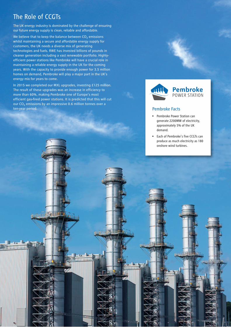
The Role of CCGTsThe UK energy industry is dominated by the challenge of ensuringour future energy supply is clean, reliable and affordable.
We believe that to keep the balance between CO2 emissionswhilst maintaining a secure and affordable energy supply forcustomers, the UK needs a diverse mix of generatingtechnologies and fuels. RWE has invested billions of pounds incleaner generation including a vast renewable portfolio. Highly-efficient power stations like Pembroke will have a crucial role inmaintaining a reliable energy supply in the UK for the comingyears. With the capacity to provide enough power for 3.5 millionhomes on demand, Pembroke will play a major part in the UK’senergy mix for years to come.
In 2015 we completed our MXL upgrades, investing £125 million.The result of these upgrades was an increase in efficiency tomore than 60%, making Pembroke one of Europe’s mostefficient gas-fired power stations. It is predicted that this will cutour CO2 emissions by an impressive 0.6 million tonnes over aten-year period. Pembroke Facts
• Pembroke Power Station cangenerate 2200MW of electricity,approximately 5% of the UKdemand.
• Each of Pembroke’s five CCGTs canproduce as much electricity as 180onshore wind turbines.
15
At Pembroke, our teams of skilled operators and engineers arecontinuously working hard to achieve new levels of flexibility forthe plant. CCGTs were originally designed to be operating 24/7at full load; however, with the recent emergence of renewablessuch as wind generation, CCGTs have to operate more flexibly.When wind generation is low, the demand for CCGT generationincreases, and vice versa.
We are always looking for new innovative ways of improvingstation performance, ensuring that we can react even morerapidly to changes in consumer power demand. With the abilityto reach its full output in under 45 minutes, Pembroke plays avital role in balancing the National Grid. When the UK’s energysystem is under stress, the station can balance its output quicklyagainst other energy supplies such as wind and solar, playing akey role in keeping the country’s lights on. Based on currentpredictions the upgraded turbines are now expected to provideas much as 7% of the UK’s flexible power each year – making asignificant contribution to the UK’s energy supply.
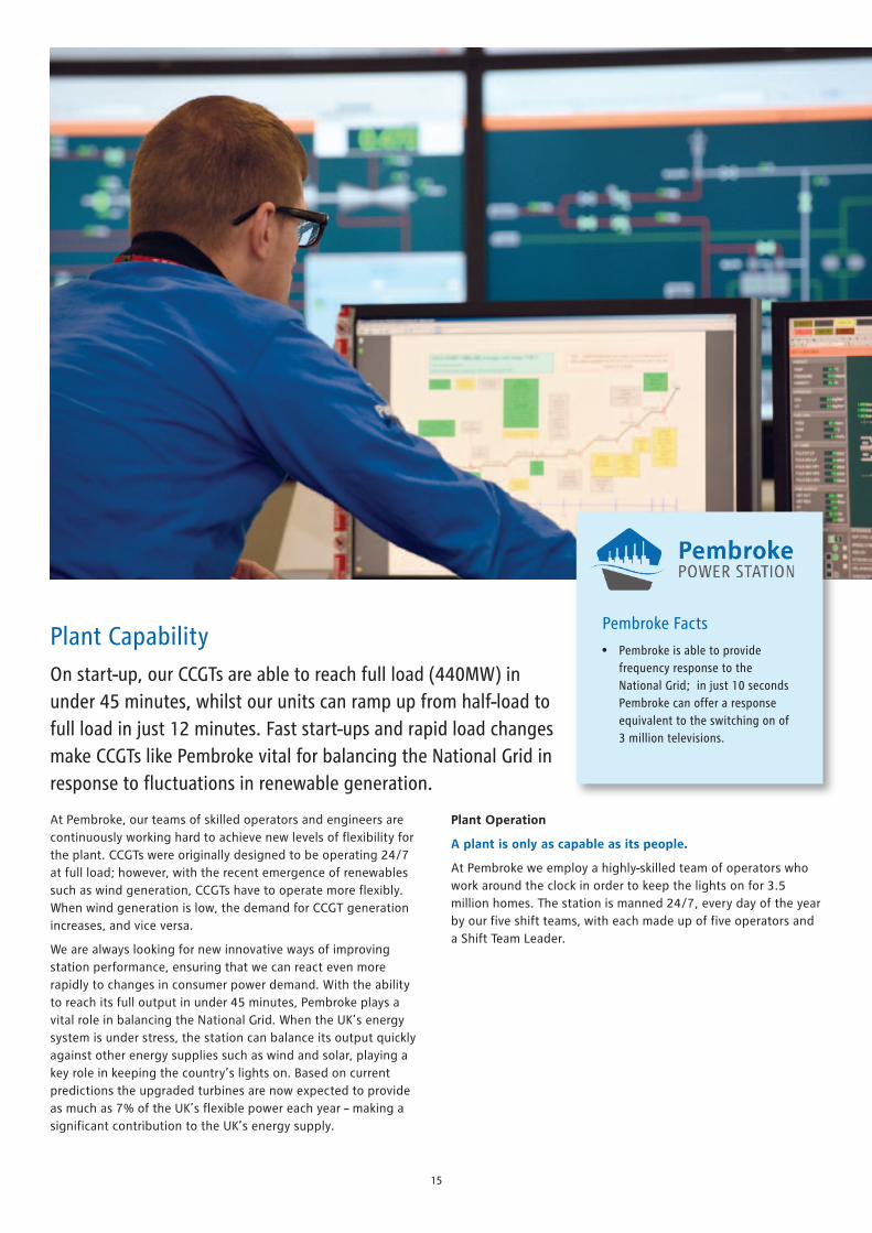
Plant CapabilityOn start-up, our CCGTs are able to reach full load (440MW) inunder 45 minutes, whilst our units can ramp up from half-load tofull load in just 12 minutes. Fast start-ups and rapid load changesmake CCGTs like Pembroke vital for balancing the National Grid inresponse to fluctuations in renewable generation.
Plant Operation
A plant is only as capable as its people.
At Pembroke we employ a highly-skilled team of operators whowork around the clock in order to keep the lights on for 3.5million homes. The station is manned 24/7, every day of the yearby our five shift teams, with each made up of five operators anda Shift Team Leader.
Pembroke Facts
• Pembroke is able to providefrequency response to theNational Grid; in just 10 secondsPembroke can offer a responseequivalent to the switching on of3 million televisions.

16
• Local Liaison Committee – this is a committee made up of localtown and county councillors, representatives from regulatorybodies and, of course, RWE staff. The committee engageswith local residents on issues connected with operations andto inform local communities of developments andopportunities at Pembroke Power Station and beyond.
• Support of local events such as the county show, town shows,community events, concerts, local awards ceremonies, localtheatre productions and events designed to attract tourism.
• A Community Fund is operated to support local grass-rootsorganisations by means of a donation. Applications areconsidered throughout the year and donations are made to awide variety of organisations from sports clubs to mother andtoddler groups.
• Election of a Station Charity – Annually, the station team selectsa local charity by means of a vote. Fund raising activities arethen focussed on this selected charity for the year.
• Corporate charity – RWE also has a corporate charity which issupported on a national basis. Pembroke Power Station hostsevents to support the corporate charity.
• Site Tours - The station has hosted a number of tours for botheducational and community purposes. Groups hosted consist
Pembroke Facts
• Pembroke Power Stationcontributes over £20million/yearto the local economy.
Extracted from Economic Impact Study,
February 2015.
of University students and local community organisations.The station also works with a local charity to provideeducational tour opportunities for school groups.
• Support of village halls and other community spaces - Thestation hosts leadership meetings and staff events in villagehalls and other such spaces, making a donation each time forits use. Many local village halls have also benefitted fromsuccessful applications to the power station’s community fund.
• Community Space - Greenhill Farm which is owned by RWE,neighbouring the power station, has been leased to a localcharitable organisation for provision of community space.
• Match funding for sponsored events – the station is verysupportive of employees’ participation in sponsored events.There is match funding available for funds raised and, thestation will sponsor registration fees for an event in order toencourage employees to get involved.
• Volunteering – many employees at the power station spendtime volunteering with numerous local organisations fromsports clubs to animal welfare. The station encourages this andensures that employees are supported in their endeavours.
The Local Community Pembroke Power Station actively contributes to our local community. We do this in a variety of different ways:

17
Join the Team! We are a small team of dedicated people who work hard tokeep the plant running safely, efficiently and flexibly.
We also have opportunities for individualswho would like to apply directly fromeducation. We review our business needon an annual basis and advertise theseopportunities accordingly:
• Apprenticeship
• Power Trainee Technician
• Year in Industry
• Graduate scheme
Roles
The types of roles that we have on site include:
• Operations Technicians
• Shift Team Leaders
• Engineering (Mechanical, Electrical, C&I, DCS)
• Maintenance (Mechanical, Electrical, C&I)
• Planning
• Environmental
• Performance/Commercial
• Health & Safety
• Learning & Development
• Chemistry
• Administration
• Finance
• Procurement
• Section Heads
• Senior Management
Recruitment All job opportunities are advertised onour website. To view currentopportunities please visitwww.rweukjobs.com where you can signup to job alerts within our area.
We also utilize the local/national pressand job websites where appropriate.
Contractors
We also have a number of contractors onsite who provide some of the essentialservices we require on site. Ourcontractors carry out their ownrecruitment in accordance with theircompany policies. The types ofcontractual roles you would expect to seeinclude the following:
• Security
• Scaffolding & Lagging
• Plant Cleaning
• Office Cleaning
• Maintenance

RWE Generation UK Pembroke Power Station
West Pennar Pembroke
Pembrokeshire SA71 5SS
T: +44(0)1646 422 101 E: [email protected]