Embed Size (px)
Citation preview
rter K
its E
mbe
dded
Web
Ser
ve
PIC
micro
cont
rolle
rs S
ta-
s fo
r ‘51
, AVR
, ST,
ation
Boa
rd
Eva
lu
rs P
roto
typing
Boa
rds M
inim
od-
Micro
proc
esor
sys
tem
s, P
CB
AVR, P
IC, S
T micro
cont
rolle
rs
ed In
Sys
tem
pro
gram
mer
s fo
r
net c
ontro
llers
, RFID
High
Spe
-
ules
for m
icro
cont
rolle
rs, e
ther
-
design
ing
Eva
luat
ion
Board
s fo
r
ethe
rnet
con
trolle
rs, R
FID H
igh
nim
odules
for m
icro
cont
rolle
rs,
Serve
rs P
roto
typing
Boa
rds
mi-
lers
Sta
rter K
its E
mbe
dded
Web
‘51,
AVR, S
T, P
IC m
icro
cont
rol-
Spe
ed In
Sys
tem
s pr
ogra
mm
e-
roco
ntro
llers
Sta
rter K
its E
mbe
-
ards
for `
51, A
VR, S
T, P
IC m
ic-
PCB d
esigning
Eva
luat
ion
Bo-
ollers
Micro
proc
esor
sys
tem
s,
rs fo
r AVR
, PIC
, ST m
icro
cont
rl-
dded
Web
Ser
wer
s Pro
totyping
mer
s fo
r AVR
, PIC
, ST m
icro
co-
High
Speed
In S
yste
m p
rogr
am-
cont
rolle
rs, e
ther
net c
ontro
llers
,
Boa
rds M
inim
odules
for m
icro
-
c
ontro
llers
Micro
proc
esor
B
oard
s
ning
Eva
luat
ion
Sys
tem
s, P
CB D
esig-
R
Many ideas one solution
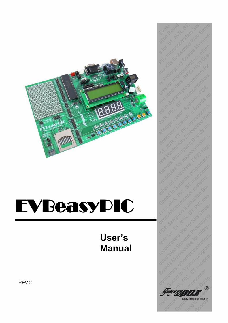
EVBeasyPIC
User’s
Manual REV 2

2
CONTENTS
1. Introduction....................................................................................................................................... 3
Available Version ............................................................................................................................... 3
2. Board Layout .................................................................................................................................... 4
Schematic .............................................................................................................................................. 4
Parts Description ............................................................................................................................... 5
3. Available Microcontrollers ........................................................................................................ 5
4. Power Supply .................................................................................................................................... 7
5. Peripheral Units .............................................................................................................................. 8
LED Diodes ............................................................................................................................................. 8
DataFlash Memory ............................................................................................................................. 8
1-Wire Connector ................................................................................................................................ 9
I2C Connector ...................................................................................................................................... 9
RS232 Interface .................................................................................................................................. 9
Switches ............................................................................................................................................... 10
Relay ....................................................................................................................................................... 10
Buzzer ..................................................................................................................................................... 11
Potentiometers .................................................................................................................................. 11
7-Segment LED Displays .............................................................................................................. 12
LM35 Thermometer ......................................................................................................................... 12
RTC DS1307 ........................................................................................................................................ 12
LCD Display ......................................................................................................................................... 13
USB-B Interface ................................................................................................................................ 13
SD/MMC Card Slot ............................................................................................................................ 14
CAN Interface ..................................................................................................................................... 15
CONT Potentiometer ...................................................................................................................... 15
AREF Potentiometer ....................................................................................................................... 15
3V3 Potentiometer .......................................................................................................................... 15
RESET Switch .................................................................................................................................... 15
6. Connectors Description ............................................................................................................ 16
7. Jumpers and LED Description ............................................................................................... 18
8. Technical Support ....................................................................................................................... 18
9. Guarantee......................................................................................................................................... 18
10. Schematic .................................................................................................................................... 18

3
1. Introduction
EVBeasyPIC is a development board designer for the hobbyist and engineers who want to quickly prototype their system based on 8-bit PIC microcontrollers from Microchip. Developer has access to all pins of the micro, which are brought to the header (pin connectors) and labeled accordingly. Depending upon the board`s configuration (listed versions) some or all of the following components are found on the board: thermometer, potentiometer, relay, buzzer, RTC (real time clock), four seven-segment LED, RS232 interface,1-Wire connector, I2C connector, ICSP connector, external FLASH memory, CAN interface, SD/MMC Card slot, USB-B connector and LCD display (2x16). The pin headers provided allow easy access to all these components. In addition, there are eight micro-switches and eight diodes which could be connected to any of the pin connectors or additional components, which may be placed on the large, adjacent prototype area. The power circuitry on board (bridge, voltage regulator) eliminates the need for an external regulated power supply. This board comes with the several examples of the C code routines (source from), to facilitate testing and quick development in using the board`s resources.
Available Version
The set EVBeasyPIC is sold in the following version:
Processor PIC18F4550
All connectors
USB-B
SD/MMC card slot (VTG = 3.3V !!!)
Four 7-segment LEDs,
Diodes and switches
Relay 10A 125VAC + LED
Buzzer
Two potentiometers
1-Wire and I2C connectors
LM35 thermometer
RS232 interface + TxD RxD LEDs
CAN interface (VTG = 3.3V !!!)
DS1307 Real Time Clock ant 3.6V accumulator
External oscillator 8MHz
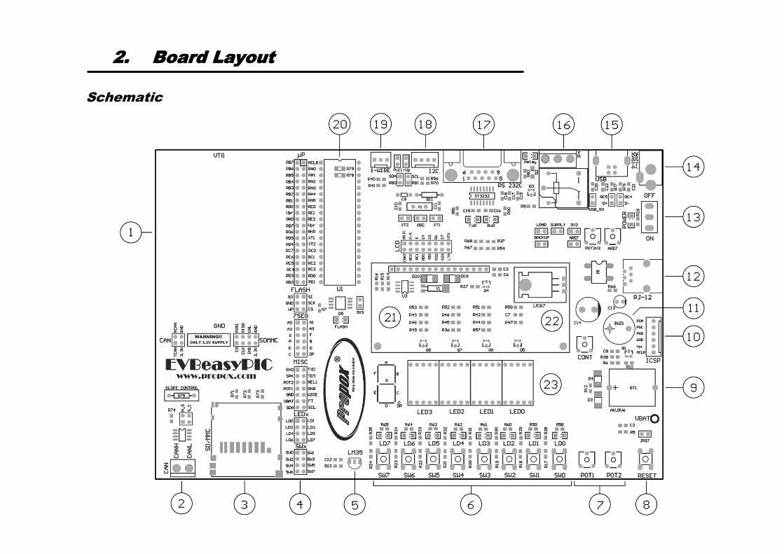
2. Board Layout
Schematic
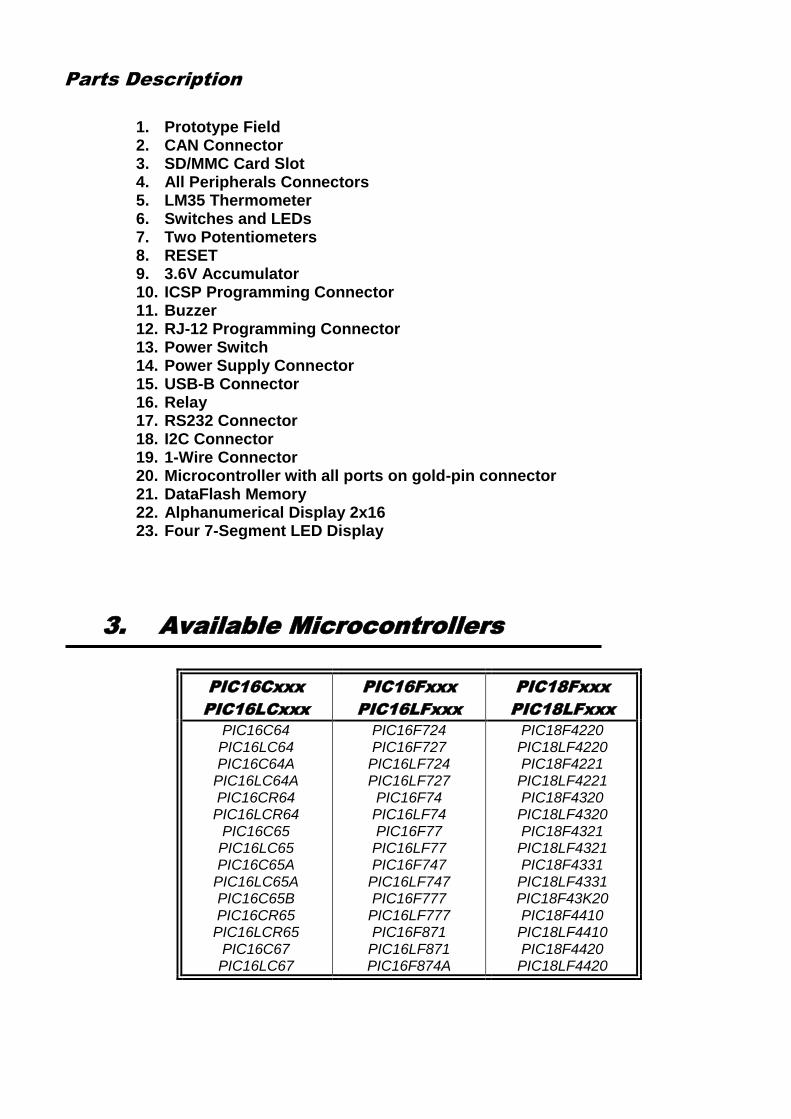
Parts Description
1. Prototype Field 2. CAN Connector 3. SD/MMC Card Slot 4. All Peripherals Connectors 5. LM35 Thermometer 6. Switches and LEDs 7. Two Potentiometers 8. RESET 9. 3.6V Accumulator 10. ICSP Programming Connector 11. Buzzer 12. RJ-12 Programming Connector 13. Power Switch 14. Power Supply Connector 15. USB-B Connector 16. Relay 17. RS232 Connector 18. I2C Connector 19. 1-Wire Connector 20. Microcontroller with all ports on gold-pin connector 21. DataFlash Memory 22. Alphanumerical Display 2x16 23. Four 7-Segment LED Display
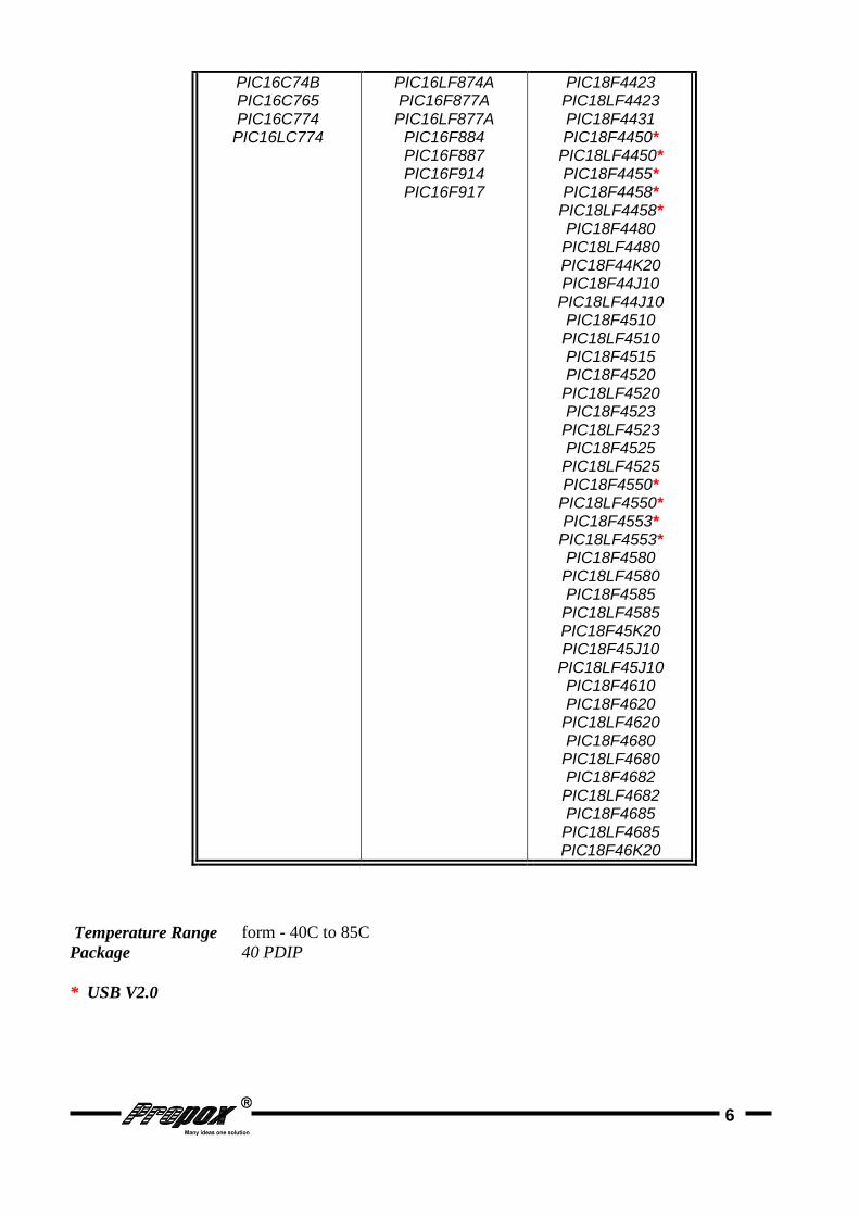
3. Available Microcontrollers
PIC16Cxxx
PIC16LCxxx
PIC16Fxxx
PIC16LFxxx
PIC18Fxxx
PIC18LFxxx
PIC16C64 PIC16LC64 PIC16C64A
PIC16LC64A PIC16CR64 PIC16LCR64
PIC16C65 PIC16LC65 PIC16C65A
PIC16LC65A PIC16C65B PIC16CR65 PIC16LCR65
PIC16C67 PIC16LC67
PIC16F724 PIC16F727
PIC16LF724 PIC16LF727 PIC16F74 PIC16LF74 PIC16F77 PIC16LF77 PIC16F747
PIC16LF747 PIC16F777
PIC16LF777 PIC16F871
PIC16LF871 PIC16F874A
PIC18F4220 PIC18LF4220 PIC18F4221 PIC18LF4221 PIC18F4320 PIC18LF4320 PIC18F4321 PIC18LF4321 PIC18F4331 PIC18LF4331 PIC18F43K20 PIC18F4410 PIC18LF4410 PIC18F4420 PIC18LF4420
6
PIC16C74B PIC16C765 PIC16C774
PIC16LC774
PIC16LF874A PIC16F877A PIC16LF877A
PIC16F884 PIC16F887 PIC16F914 PIC16F917
PIC18F4423 PIC18LF4423 PIC18F4431 PIC18F4450*
PIC18LF4450* PIC18F4455* PIC18F4458*
PIC18LF4458* PIC18F4480 PIC18LF4480 PIC18F44K20 PIC18F44J10 PIC18LF44J10 PIC18F4510 PIC18LF4510 PIC18F4515 PIC18F4520 PIC18LF4520 PIC18F4523 PIC18LF4523 PIC18F4525 PIC18LF4525 PIC18F4550*
PIC18LF4550* PIC18F4553*
PIC18LF4553* PIC18F4580 PIC18LF4580 PIC18F4585 PIC18LF4585 PIC18F45K20 PIC18F45J10 PIC18LF45J10 PIC18F4610 PIC18F4620 PIC18LF4620 PIC18F4680 PIC18LF4680 PIC18F4682 PIC18LF4682 PIC18F4685 PIC18LF4685 PIC18F46K20
Temperature Range form - 40C to 85C
Package
* USB V2.0
40 PDIP
7
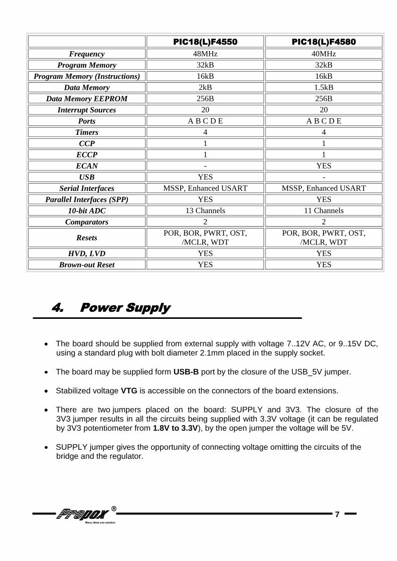
PIC18(L)F4550 PIC18(L)F4580
Frequency 48MHz 40MHz
Program Memory 32kB 32kB
Program Memory (Instructions) 16kB 16kB
Data Memory 2kB 1.5kB
Data Memory EEPROM 256B 256B
Interrupt Sources 20 20
Ports A B C D E A B C D E
Timers 4 4
CCP 1 1
ECCP 1 1
ECAN - YES
USB YES -
Serial Interfaces MSSP, Enhanced USART MSSP, Enhanced USART
Parallel Interfaces (SPP) YES YES
10-bit ADC 13 Channels 11 Channels
Comparators 2 2
Resets POR, BOR, PWRT, OST,
/MCLR, WDT
POR, BOR, PWRT, OST,
/MCLR, WDT
HVD, LVD YES YES
Brown-out Reset YES YES
4. Power Supply
The board should be supplied from external supply with voltage 7..12V AC, or 9..15V DC, using a standard plug with bolt diameter 2.1mm placed in the supply socket.
The board may be supplied form USB-B port by the closure of the USB_5V jumper.
Stabilized voltage VTG is accessible on the connectors of the board extensions.
There are two jumpers placed on the board: SUPPLY and 3V3. The closure of the 3V3 jumper results in all the circuits being supplied with 3.3V voltage (it can be regulated by 3V3 potentiometer from 1.8V to 3.3V), by the open jumper the voltage will be 5V.
SUPPLY jumper gives the opportunity of connecting voltage omitting the circuits of the bridge and the regulator.

8
5. Peripheral Units
LED Diodes
The board has 8 LED diodes, which make the simplest interface between the system and the user. This is especially useful for the beginners, who want to manipulate or debug their program with different hardware configurations. The diode turns on after grounding of the associated Ldn (n = 0 – 8) pin.
Figure 1. LED Diodes
DataFlash Memory
Board have external DataFlash AT45DB041B memory with 4MB space. Memory is power by diode, which decrease voltage. Is a possibility to power without that diode, correctly from supply source by short jumper 3V3 placed near memory.
Figure 2. DataFlash Memory Implementation
9
1-Wire Connector
Allows to connect an external devices using an 1-wire interface.
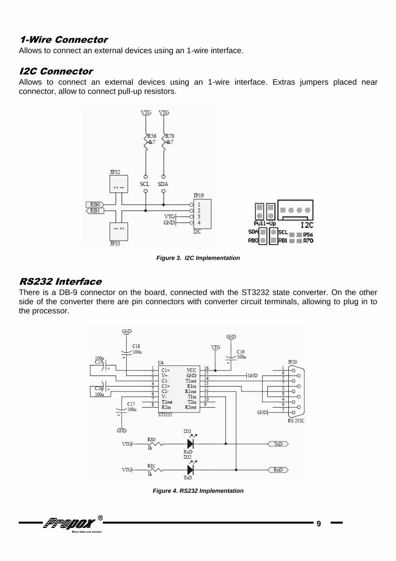
I2C Connector
Allows to connect an external devices using an 1-wire interface. Extras jumpers placed near connector, allow to connect pull-up resistors.
Figure 3. I2C Implementation
RS232 Interface
There is a DB-9 connector on the board, connected with the ST3232 state converter. On the other side of the converter there are pin connectors with converter circuit terminals, allowing to plug in to the processor.
Figure 4. RS232 Implementation
10
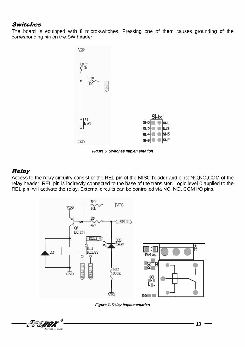
Switches
The board is equipped with 8 micro-switches. Pressing one of them causes grounding of the corresponding pin on the SW header.
Figure 5. Switches Implementation
Relay
Access to the relay circuitry consist of the REL pin of the MISC header and pins: NC,NO,COM of the relay header. REL pin is indirectly connected to the base of the transistor. Logic level 0 applied to the REL pin, will activate the relay. External circuits can be controlled via NC, NO, COM I/O pins.
Figure 6. Relay Implementation

11
Buzzer
The board has an acoustic indicator turned on and off by the transistor. The base of the transistor is connected to the SPK pin of the MISC header. Logic level `0` applied to the SPK pin, will activate the speaker.
Figure 7. Buzzer Impedance
Potentiometers
The board is equipped with two potentiometers, allowing for simulation of the analog circuit outputs. The potentiometer enables the adjustment of voltage in the range 0-VTG. The potentiometers output is accessible on POT1 and POT2 pin of the MISC connector. Customer can choose a resistance of potentiometer during buying board.
Figure 8. Potentiometers Implementation

12
7-Segment LED Displays
The board is equipped with four 7-segment led display. They make an interface between the system and the user, allowed to display up to four chars. Each led display has two anodes, seven segments and DP (digital point), which become active after applied to their pin logic level ‘0’.
Figure 9. 7-Segment LED Display Implementation
LM35 Thermometer
Thermometer LM35 allows to measure an environment`s temperature and display it on seven-segment LEDs or on LCD display.
RTC DS1307
The board has one real time clock with accumulator 3V6 (The board can be also supply form accumulator). The clock communicates with the micro through the I2C interface. All the connections needed for controlling the DS1307 circuit are brought out to the RTC pin header. The accumulator pin is also placed on the header.
Figure 10. RTC Implementation

13
LCD Display
The board has one LCD display interface. The LCD connector has four data lines and two control lines: strobe line E and control line R/S. The display R/W line is permanently connected to ground; all other lines are available at the pin header. The adjustment of contrast id done by two way:
by potentiometer ADJ CONT which output pin ADJC must be then connected with LCD`s pin CONT.
programmable, then LCD`s pin CONT must be connected to the processor.
Figure 11. LCD Display Implementation
USB-B Interface
Board is equipped with USB interface connector. USB allows connection with PC or other USB host and transfer data with up to 12MB/s speed. Along with USB connector there are RC filtering circuits and jumper for connecting USB bus power with board +5V voltage.
Figure 12. USB Implementation
14
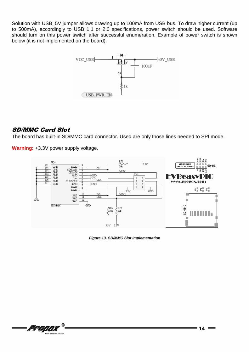
Solution with USB_5V jumper allows drawing up to 100mA from USB bus. To draw higher current (up to 500mA), accordingly to USB 1.1 or 2.0 specifications, power switch should be used. Software should turn on this power switch after successful enumeration. Example of power switch is shown below (it is not implemented on the board).
SD/MMC Card Slot
The board has built-in SD/MMC card connector. Used are only those lines needed to SPI mode. Warning: +3.3V power supply voltage.
Figure 13. SD/MMC Slot Implementation

15
CAN Interface
The board have CAN transceiver SN65HVD230 form Texas Instruments with terminal-block connector.
Warning: +3.3V power supply voltage.
Figure 14. CAN Transceiver Implementation
CONT Potentiometer
There is a ADJ CONT potentiometer, which allows to control the contrast on LCD. Then output pin ADJC must be connected with LCD`s pin CONT.
AREF Potentiometer
Allow to adjust reference voltage of ADC in range from 0V to VTG. It is connected by jumper AREF to one of microcontroller’s port.
3V3 Potentiometer
The board is equipped with one potentiometer, allowing to regulate voltage VTG between 3.3 – 1,25 V ( even if 3V3 jumper is closed).
RESET Switch
Allow to apply external reset.
On board was implemented Slope Control by place resistor R75. There is a possibility to choose two work condition: High Speed and Slope Control by placed jumper JP27.
16
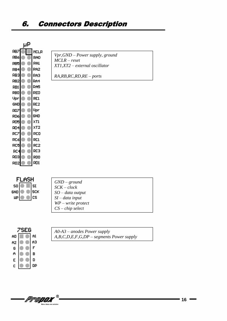
6. Connectors Description
Vpr,GND – Power supply, ground
MCLR – reset
XT1,XT2 – external oscillator
RA,RB,RC,RD,RE – ports
GND – ground
SCK – clock
SO – data output
SI – data input
WP – write protect
CS – chip select
A0-A3 – anodes Power supply
A,B,C,D,E,F,G,DP – segments Power supply

17
RxD,TxD – write and read data from RS232
SPK – Buzzer
TEM – LM35
POT1,POT2 – potentiometers
REL – relay
WIRE – 1-Wire
VBAT – accumulator Power supply
FT – RTC correction line
SDA – RTC data
SCL – RTC clock
LD0–LD7 –LEDs
SW0-SW7 – switches
3.3V, GND – Power supply and ground
TCAN,RCAN –CAN transceiver
3.3V,GND – Power supply and ground
CS – chip select
MOSI – data input
MISO – data output
CLK – clock
INS – insert card
UNL – unlock card

18
7. Jumpers and LED Description
8. Technical Support
In order to obtain technical assistance please contact [email protected] . In the request please include the following information:
Number of the board version (e.g. REV 1)
A detailed description of the problem
9. Guarantee
The EVBeasyPIC board are covered by a six-month guarantee. All faults and defects not caused by the user will be removed at the Producer’s cost. Transportation costs are borne by the buyer. The Producer takes no responsibility for any damage and defects caused in the course of using the EVBeasyPIC.
10. Schematic

19