Embed Size (px)
Citation preview

Evaluation of Passive Diffusion Bag and Dialysis Samplers in Selected Wells at Hickam Air Force Base, Hawaii, July 2001
Prepared in cooperation with theAIR FORCE CENTER FOR ENVIRONMENTAL EXCELLENCE
U.S. Department of the InteriorU.S. Geological Survey
Water-Resources Investigations Report 02-4059

Evaluation of Passive Diffusion Bag and DialysisSamplers in Selected Wells at Hickam Air ForceBase, Hawaii, July 2001
By Don A. Vroblesky and Tasha Pravecek
U.S. Geological Survey
Water-Resources Investigations Report 02-4159
Prepared in cooperation with the
AIR FORCE CENTER FOR ENVIRONMENTAL EXCELLENCE
Columbia, South Carolina2002

U.S. DEPARTMENT OF THE INTERIORGALE A. NORTON, Secretary
U.S. GEOLOGICAL SURVEYCharles G. Groat, Director
Use of trade, product, or firm names in this publication is for descriptive purposes only and does not imply endorsement by the U.S. Geological Survey
For additional information write to:
District Chief U.S. Geological SurveySuite 129720 Gracern RoadColumbia, SC 29210-7651
Additional information about water resources in South Carolina is available on the World Wide Web at http://sc.water.usgs.gov
Copies of this report can be purchased from:
U.S. Geological SurveyBranch of Information ServicesBox 25286Denver, CO 80225-0286888-ASK-USGS

Contents III
CONTENTSAbstract .................................................................................................................................................................................... 1Introduction.............................................................................................................................................................................. 2
Site Description.............................................................................................................................................................. 2Acknowledgments.......................................................................................................................................................... 2
Methods.................................................................................................................................................................................... 2Diffusion Sampler Construction and Deployment......................................................................................................... 5Water-Sample Collection and Diffusion-Sampler Recovery ......................................................................................... 6Data Evaluation.............................................................................................................................................................. 6
Results and Discussion ............................................................................................................................................................ 8Inorganic Solutes............................................................................................................................................................ 8Volatile Organic Compounds ....................................................................................................................................... 15Advantages and Limitations of Diffusion Samplers at Hickam Air Force Base ......................................................... 24
Summary and Conclusions .................................................................................................................................................... 25References.............................................................................................................................................................................. 27
Figures
1. Map showing locations of observation wells at Hickam Air Force Base, Hawaii, July 2001 ........................................ 32. Photograph showing dialysis bag on perforated pipe with the outer low-density polyethylene mesh pulled
partway back ................................................................................................................................................................... 53. Graph showing comparison of chloride, sulfate, and iron concentrations in low-flow samples
to concentrations in dialysis samples at the same depth, Hickam Air Force Base, Hawaii, July 2001....................................................................................................................................................................... 11
4-6. Graphs showing vertical distribution of:4. Chloride in dialysis and low-flow samples from wells at Hickam Air Force Base,
Hawaii, July 2001 .................................................................................................................................................... 135. Sulfate in dialysis and low-flow samples from wells at Hickam Air Force Base,
Hawaii, July 2001 .................................................................................................................................................... 146. Volatile organic compounds in dialysis and low-flow samples from well SS01 MW-12, Hickam Air
Force Base, Hawaii, July 2001................................................................................................................................. 227. Photograph showing discoloration of dialysis sampler membrane after 2 weeks of deployment in a well,
Hickam Air Force Base, Hawaii, July 2001 ................................................................................................................. 24
Tables
1. Well and sampling data, Hickam Air Force Base, Hawaii, July 2001 ............................................................................ 42. Concentrations of inorganic solutes in dialysis, passive diffusion bag, and low-flow samples, Hickam Air
Force Base, Hawaii, July 2001 ....................................................................................................................................... 93. Statistical comparison of chloride, sulfate, and iron concentrations in dialysis and low-flow samples,
Hickam Air Force Base, Hawaii, July 2001 ................................................................................................................. 124. Concentrations of organic solutes in dialysis, passive diffusion bag, and low-flow samples, Hickam Air
Force Base, Hawaii, July 2001 ..................................................................................................................................... 165. Summary of diffusion sampler ability to produce an accurate representation of the ambient water in
tested wells at Hickam Air Force Base, Hawaii, July 2001.......................................................................................... 23

IV Contents
CONVERSION FACTORS, VERTICAL DATUM, ABBREVIATIONS, AND ACRONYMS
Sea Level: In this report, "sea level" refers to the National Geodetic Vertical Datum of 1929—A geodetic datum derived from a general adjustment of the first-order level nets of the United States and Canada, formerly called Sea Level Datum of 1929.
Chemical concentration: In this report, chemical concentration in water is expressed in metric units as milligrams per liter (mg/L) or micrograms per liter (µg/L).
Temperature can be converted from degrees Celsius (οC) to degrees Fahrenheit (οF) as follows: οC = (οF –32) x 5/9
Multiply By To obtain
inch (in.) 25.4 millimeter (mm)
foot (ft) 0.3048 meter
mile (mi) 1.609 kilometer
gallon (gal) 3.785 liter
AFB Air Force Base
EDTA ethylene diaminetetra acetic acid
LDPE low-density polyethylene
µ micron
mL/min milliliter per minute
PDB passive diffusion bag
RPD ralative percent difference
USGS U.S. Geological Survey
VOC volatile organic compound

Abstract 1
Field comparisons of chemical concentrations obtained from dialysis samplers,passive diffusion bag samplers, and low-flow samplers showed generally close agree-ment in most of the 13 wells tested during July 2001 at Hickam Air Force Base, Hawaii.The data for chloride, sulfate, iron, alkalinity, arsenic, and methane appear to show thatthe dialysis samplers are capable of accurately collecting a passive sample for theseconstituents. In general, the comparisons of volatile organic compound concentrationsshowed a relatively close correspondence between the two different types of diffusionsamples and between the diffusion samples and the low-flow samples collected in mostwells. Divergence appears to have resulted primarily from the pumping method, eitherproducing a mixed sample or water not characteristic of aquifer water moving throughthe borehole under ambient conditions. The fact that alkalinity was not detected in thepassive diffusion bag samplers, even when deployed in alkaline water, implies that thepassive diffusion bag samplers can be used to collect volatile organic compounds fromhighly alkaline waters without volatilization loss from effervescence, which can occurwhen a sample is acidified for preservation. Both dialysis and passive diffusion bagsamplers are relatively inexpensive and can be deployed rapidly and easily. Passivediffusion bag samplers are intended for sampling volatile organic compounds only, butdialysis samplers can be used to sample both volatile organic compounds and inorganicsolutes. Regenerated cellulose dialysis samplers, however, are subject to biodegradationand probably should be deployed no sooner than 2 weeks prior to recovery.
Evaluation of Passive Diffusion Bag and Dialysis Samplers in Selected Wells at Hickam Air Force Base, Hawaii, July 2001
By Don A. Vroblesky1 and Tasha Pravecek2
ABSTRACT
1 U.S. Geological Survey, Columbia, South Carolina.2 Air Force Center for Environmental Excellence, San Antionio, Texas.

2 Evaluation of Passive Diffusion Bag and Dialysis Samplers in Selected Wells at Hickam Air Force Base, Hawaii, July 2001
Diffusion samplers have been used in environ-mental studies for several years. Low-density polyeth-ylene (LDPE) diffusion samplers have been shown to be a cost-effective alternative to conventional methods to provide samples of volatile organic compounds (VOCs) in ground water at wells (Vroblesky and Hyde, 1997; Parsons Engineering Science, Inc., 1999; Church, 2000; Hare, 2000; McClellan AFB Environmental Management Directorate, 2000; Vroblesky and others, 2000; Vroblesky and Peters, 2000; Vroblesky and Petkewich, 2000) and at zones where VOC-contaminated ground water discharges to surface water (Vroblesky and others, 1991, 1996, 1999; Vroblesky and Robert-son, 1996; Lyford and others, 1999a,b; Savoie and others, 1999, 2000; Vroblesky, 2000). In addition, a wide variety of diffusion samplers have been used to determine porewater concentrations of inorganic solutes. Samplers for inorganic constitutents include variations of the samplers introduced by Hesslein (1976) and Mayer (1976). Membranes have included nylon screens (Paludan and Morris, 1999; Vroblesky and others, 2002), filter paper (Davis and Atkins, 2001), and dialysis membranes (Mayer, 1976; Bottomly and Bayley, 1984; Ronen and others, 1986; Webster and others, 1998; Diog and Liber; 2000, Vroblesky and others, 2002), among others. Mulitport configurations of dialysis cells have been used to define heterogeneity in the screened intervals of wells (Ronen and others, 1986, Kaplan and others, 1991).
Although use of the LDPE passive diffusion bag (PDB) samplers has provided cost savings (McClellan AFB Environmental Management Directorate, 2000), their application has been limited to sites where VOCs were the target contaminants. If a simple, inexpensive diffusion sampler were available that was capable of sampling both VOCs and inorganic solutes, then the scope of wells suitable for application of diffusion sampling would be substantially increased. Tests of dialysis bags deployed in wells implies that these types of samplers have the potential to provide a representa-tive sample of both VOCs and ionic solutes from ground water (Kaplan and others, 1991; Vroblesky and others, 2002; Thomas Imbrigiotta, U.S. Geological Survey, written commun., 2002).
The purpose of this report is to compare ground-water concentrations of both VOCs and inorganic sol-utes obtained from side-by-side tests of an updated dial-ysis sampler configuration (Vroblesky and others, 2002)
and PDB samplers to concentrations obtained by using low-flow samplers in wells. The tests were conducted during July 2001 in 13 wells at Hickam Air Force Base (AFB), Hawaii, in cooperation with the Air Force Center for Environmental Excellence, San Antonio, Texas.
Site Description
Ground water at Hickam AFB is recharged by precipitation and lateral flow from upgradient areas. Discharge is predominantly to surface-water bodies. Depth to the water table at the tested wells ranges from about 7.3 to 12.7 ft below top of casing. Drillers’ logs indicate that the water-table aquifer consists primarily of weathered and fractured tuff and sandy coralline gravel (Mark Peterson, 15 Civil Engineering Squadron, U.S. Air Force, written commun., 2002). Four areas containing contaminated ground water at Hickam AFB were examined during this investigation: site SS01, which contains a gas station and a residential area; site SS11, which is a ramp area near the runway; site SS13, which includes a tank farm; and site SS15, which is a golf course near the flight line (fig. 1). The contami-nants at sites SS01, SS11, and SS15 are primarily hydrocarbons related to petroleum. Light non-aqueous-phase liquid is present in some parts of these sites. Site SS13 historically has had high mercury and copper values, but these solutes were either not detected during this investigation, or the concentrations were flagged as having laboratory uncertainties.
Acknowledgments
This investigation would not have been possible without the assistance of William Grannis and Mark Peterson of the 15 Civil Engineering Squadron, U.S. Air Force, Hickam AFB, Hawaii. We also would like to thank Shana Bagley and Manish Joshi of Earth Tech, San Antonio, Texas. Ms. Bagley provided valuable field assistance and Mr. Joshi provided a substantial amount of organizational and logistical assistance.
Diffusion samplers and PDB samplers were deployed in 13 wells at Hickam AFB, Hawaii, as a test to compare diffusion-sampling methods to a conven-tional sampling method. The conventional method used for comparison was low-flow sampling. Well and sampling data are listed in table 1.
INTRODUCTION
METHODS

Methods 3
Fig
ure
1. L
ocat
ions
of o
bser
vatio
n w
ells
at H
icka
m A
ir F
orce
Bas
e, H
awai
i, Ju
ly 2
001.

4 Evaluation of Passive Diffusion Bag and Dialysis Samplers in Selected Wells at Hickam Air Force Base, Hawaii, July 2001
Table 1. Well and sampling data, Hickam Air Force Base, Hawaii, July 2001
[ft BLS, below land surface; ft BTOC, feet below top of casing;---, data not collected; all samplers were deployed for 14 days]
Well
Well diam-eter
(inches)
Screen length (feet)
Screened interval (ft BLS)
Flow meter test?
Depth to water at time
of deploy-
ment (ft BTOC)
Sounded depth to
well bottom
(ft BTOC)
Satu-rated
interval (feet)
Distance from well bottom to sampler center (feet)
Depth of sampler center
(ft BTOC)
Sampler deploy-
ment date
Sampler recovery
date
Low-flow sampling
date
SITE SS01
SS01 MW-2 4 15 9.5-24.5 no 14.56 24.34 9.78 8.3 16.04 07/10/01 7/24/01 ---
5.3 19.04 07/10/01 7/24/01 07/26/01
2.3 22.04 07/10/01 7/24/01 ---
SS01 MW-6 4 15 9.5-24.5 yes 9.45 24.83 15.38 8.3 16.53 07/12/01 7/26/01 ---
5.3 19.53 07/12/01 7/26/01 07/27/01
2.3 22.53 07/12/01 7/26/01 ---
SS01 MW-8 4 15.5 4-19.5feet BTOC
no 9.09 18.5 9.41 8.3 10.2 07/10/01 7/24/01 07/26/01
5.3 13.2 07/10/01 7/24/01 ---
2.3 16.2 07/10/01 7/24/01 ---
SS01 MW-11 4 15 9.5-24.5 yes 14.4 24.61 10.21 8.3 16.31 07/12/01 7/26/01 ---
5.3 19.31 07/12/01 7/26/01 07/27/01
2.3 22.31 07/12/01 7/26/01 ---
SS01 MW-12 4 15 9.5-24.5 yes 12.73 24.68 11.95 11.3 13.38 07/12/01 7/26/01 ---
8.3 16.38 07/12/01 7/26/01 07/27/01
5.3 19.38 07/12/01 7/26/01 ---
2.3 22.38 07/12/01 7/26/01 ---
SITE SS11 (ramp area)
SS11 MW-8 4 10 4-14 no 7.61 14.49 6.88 4.8 9.69 07/11/01 7/25/01 07/26/01
1.8 12.69 07/11/01 7/25/01 ---
SITE SS13 (tank farm)
SS13 MW-4 4 14.5 5-19.5 yes 8.13 19.83 11.7 10.3 9.53 07/12/01 7/26/01 ---
7.3 12.53 07/12/01 7/26/01 07/27/01
4.3 15.53 07/12/01 7/26/01 ---
1.3 18.53 07/12/01 7/26/01 ---
SS13 MW-10 4 10.6 5-15.6 7.29 15.09 7.8 5.3 9.79 07/11/01 7/25/01 07/26/01
2.3 12.79 07/11/01 7/25/01 ---
SS13 MW-17 4 10 5-15 no 6.78 15.1 8.32 7.3 7.8 07/11/01 7/25/01 ---
4.3 10.8 07/11/01 7/25/01 07/26/01
1.3 13.8 07/11/01 7/25/01 ---
SITE SS15 (golf course)
SS15 MW-2 4 10 7.5-17.5 no 9.96 17.94 7.98 5.6 12.34 07/10/01 7/24/01 07/25/01
2 15.94 07/10/01 7/24/01 ---
SS15 MW-4 4 10 5-15 no 6.55 14.02 7.47 5.9 8.12 07/10/01 7/24/01 07/25/01
2 12.02 07/10/01 7/24/01 ---
SS15 MW-5 4 15 1.5-14.5 5.07 15 9.93 8.3 6.7 07/11/01 7/25/01 ---
5.3 9.7 07/11/01 7/25/01 07/26/01
2.3 12.7 07/11/01 7/25/01 ---
SS15 GT-K5 4 17 3-20 TOC yes 7.61 22.4 14.79 12.3 10.1 07/12/01 7/26/01 ---
9.3 13.1 07/12/01 7/26/01 07/27/01
6.3 16.1 07/12/01 7/26/01 ---
3.3 19.1 07/12/01 7/26/01 ---

Methods 5
Diffusion Sampler Construction and Deployment
The PDB samplers consisted of sealed polyethylene bags containing anaerobic deionized water. The general method of deployment and recovery for PDB samplers is discussed in Vroblesky (2001). The PDB samplers used in this investigation were purchased commercially (Eon Products, Inc.). The samplers were about 1 ft long and were filled in the field by means of a removable plug at the sampler bottom.
Each dialysis sampler was constructed onsite and consisted of a perforated acetate or plastic pipe inside a sleeve of high-grade regenerated cellulose tubular dialy-sis membrane (Membrane Filtration Products, Inc., Seguin, Texas) with an outer protective LDPE mesh (Vroblesky and others, 2002).
The membranes used for the dialysis samplers had a nominal molecular-weight cutoff of 8,000 daltons, or about 18 angstroms pore size, and a flat width of about 3 in. (76 mm) (cost was about $180 for a 32.8-ft roll). The dial-ysis membrane was supplied pretreated to remove sulfur compounds and residual metals. The pretreated mem-brane was packaged in a solution of methanol and ethyl-ene diaminetetra acetic acid (EDTA), which was removed by rinsing with deionized water prior to use. An alterna-tive approach not used in this investigation would be to use less expensive dry membranes (about $110-180 for a 98.4-ft roll) that must be cleaned through a series of steps that involve soaking and rinsing with deionized water, heated sodium bicarbonate solution, EDTA, and sodium azide solution to remove residual glycerol, sulfide, cad-mium, chromium, copper, iron, nickel, zinc, and lead. The inner plastic sleeve and outer protective LDPE mesh were washed with deionized water prior to use.
To construct a dialysis sampler, holes were drilled in a plastic pipe (about 1 to 1.5 ft long, 0.005 in. thick, 1.45 in. outside diameter), and the pipe then was sanded to remove burrs that could tear the membrane. The cel-lulose acetate dialysis tube was cut to a length of about 2 to 2.5 ft and was thoroughly washed with deionized water. One end of the tube was tied in a knot. The pre-cleaned perforated plastic pipe then was slid into the dialysis tube for structural support (fig. 2). The sampler was filled with deionized water at the time of sampler deployment, and the other end of the membrane was tied. The second knot was tied as closely as possible to the inner plastic pipe because, as water diffuses out of the bag, the bag volume decreases. Placing the knot as closely as possible to the inner plastic pipe reduces the amount of bag-volume lost during equilibration. The assembly was slid into a length of precleaned low-density polyethylene mesh for abrasion protection.
The structural support provided by the inner perforated acetate or plastic pipe is important to allow the sampler to retain water by preventing its collapse during diffusion. Dialysis allows equilibrium concen-trations to be achieved by two basic processes. The first involves the transfer of water from an area of low solute concentration to an area of high solute concen-tration. Thus, a diffusion sampler filled with deionized water will tend to collapse as water exits the bag when deployed in nondilute aqueous solutions. The second mechanism of dialysis transfer involves the movement of solutes from an area of high solute concentration to an area of low solute concentration. Solute transfer is the dominant mechanism by which water within the diffusion sampler achieves chemical equilibrium with water outside the diffusion sampler once the bag can no longer collapse because of the inner perforated pipe. Such a pipe is not needed for PDB samplers because polyethylene does not transmit water.
The PDB samplers and dialysis samplers were filled with anaerobic deionized water at the time of sam-pler deployment. Anaerobic water was prepared by bubbling nitrogen through approximately 5 gallons of deionized water until the dissolved oxygen concentra-tion was reduced to less than 0.5 mg/L (as measured by CheMets colorimetric methodology, Calverton, Va.). A peristaltic pump was used to transfer the water from the container into the samplers.
Deployment of the samplers in wells consisted of attaching the samplers to a weighted support line and lowering them into the well. A PDB sampler was attached to a dialysis sampler at each targeted sampling depth or horizon. Each well consisted of at least two targeted horizons (table 1), although in two wells (SS13 MW10 and SS15 MW4), inorganic data were collected at only one of the horizons.
Figure 2. Dialysis bag on perforated pipe with the outer low-density polyethylene mesh pulled partway back.
6 Evaluation of Passive Diffusion Bag and Dialysis Samplers in Selected Wells at Hickam Air Force Base, Hawaii, July 2001
Equilibration time of dialysis samplers in a laboratory study at 25 oC was between 20.5 and 92 hours (Vroblesky and others, 2002). This time range is approximately consistent with an independent test of dialysis-sampler equilibration times in which iron and bromide and a variety of chlorinated solvents attained equilibrium within 3 days (Theodore A. Ehlke, U.S. Geological Survey, written commun., 2001). Chloride and manganese attained complete equilibrium and sulfate attained 80 percent equilibrium within 48 hours (Ronen and others, 1986; Magaritz and others, 1989).
When deployed in sediment, the limiting factor in equilibration is predominantly the solute diffusion through the sediments (Webster and others, 1998). Equilibration times of various dialysis samplers for determining porewater inorganic concentrations in previous investigations include 15 to 20 days (Carignan, 1984), 100 hours in unconsolidated clay and silt (Mayer, 1976), and 10 days using a 0.45-µ polysulfone membrane (Bottomley and Bayly, 1984). A variety of studies reported that 2 weeks was adequate for equili-bration of these types of samplers in saturated sediment (Carignan and others, 1985; Gaillard and others, 1986; Tessier and others, 1989; Davis and Galloway, 1993; Hare and others, 1994; Bertolin and others, 1995). Based on these data and the previously cited laboratory inves-tigations, a minimum 2-week equilibration time was used in this investigation.
Water-Sample Collection and Diffusion-Sampler Recovery
Low-flow sampling methodology (Barcelona and others, 1994; Shanklin and others, 1995) was used to collect ground-water samples from the wells at Hickam AFB, Hawaii. The wells were purged at a rate of approximately 75-200 mL/min, until the tempera-ture, pH, and specific conductance stabilized and no additional water-level drawdowns were observed. Typically, stabilization required purging over a time period of less than 30 minutes. The low-flow ground-water samples at most wells were collected the day following retrieval of the diffusion samplers from the well. At wells SS01 MW-2 and SS01 MW-8, the low-flow samples were collected 2 days after diffusion-sample recovery.
Inorganic constituents were measured in water from dialysis samples and low-flow samples. Water samples were analyzed by U.S. Environmental Protec-tion Agency method E300.0 for anions and by method SW6010B for metals (U.S. Environmental Protection
Agency, 1983, 1992). Inorganic constituents measured during this investigation were alkalinity, arsenic, chloride, iron, lead, methane, sulfate, sulfide, and zinc; however, the suite of inorganic constituents measured at each well varied, depending on the historical sampling data of the well. Water from the dialysis, PDB, and low-flow samplers were analyzed for VOCs by using method 8260B (U.S. Environmental Protection Agency, 1999).
Duplicate diffusion samples were collected from approximately 10 percent of the sampling sites. In general, the diffusion samples compared well with their respective duplicate samples. For most organic constit-uents, differences between concentrations in diffusion samples and their duplicates were less than 15 percent or less than 2 µg/L. For inorganic constituents, differ-ences between concentrations in diffusion samples and their duplicates at concentrations above 0.5 mg/L were less than 10 percent At a concentration less than 0.5 mg/L, a dialysis iron sample differed from its dupli-cate by about 0.05 mg/L. Results of duplicate samples analyzed for VOCs by separate laboratories differed by 10 percent or less.
Data Evaluation
Statistical comparisons of the data were conducted in this investigation to provide a general comparison among sample concentrations. Caution should be exercised, however, when using statistics to compare diffusion samples to low-flow samples for a variety of reasons. Comparisons within single-well data usually involve a relatively small data set, thus reducing the confidence level of the comparison. In addition, low-flow sampling and diffusion sampling constitute two different approaches that sometimes pro-duce different types of samples. The low-flow sample typically represents some degree of mixed waters, and the diffusion sample represents only the water that con-tacted the sampler. Near interfaces of contaminant stratification, even a relatively small amount of mixing can result in low-flow sample concentrations that differ substantially from concentrations obtained by using a diffusion sampler (Vroblesky and Peters, 2000). There-fore, near interfaces of contaminant stratification, sta-tistics can produce an overly harsh evaluation of the comparison, despite the fact that both low-flow and diffusion methods may be producing accurate results.
When the two methods disagree at a particular depth in a chemically stratified well, a more reasonable approach to resolving the difference is to visually compare a plot of concentrations defined by multiple

Methods 7
diffusion samplers to concentrations obtained by low-flow samplers. The evaluation may reveal that the low-flow sample represents a mixing of water over some interval, whereas the diffusion samples represent a more discrete evaluation of the same waters. In this case, both methods correctly represent the ambient concentrations despite a difference in concentrations. On the other hand, if the evaluation shows that the low-flow sampler collects water that does not move through the screened or open interval under nonpumping condi-tions, then the resulting concentration difference indi-cates that the two methods are sampling different waters. These conclusions, which require an in-well comparison, are lost when a statistical approach is used in which the population consists of many wells across a particular site and the data from each well are the result from the two methods at a single corresponding depth. Again, this statistical approach has the potential to pro-duce an overly harsh evaluation of the comparison.
If these cautions are taken into account, however, a statistical evaluation sometimes can provide mean-ingful comparisons. Although it is probable that the statistical evaluation may provide an overly harsh evaluation of the comparison, it is less likely that the evaluation will falsely produce a favorable compari-son. If the relative percent difference (RPD) between concentrations obtained by the two methods at a par-ticular depth is small, then it probably is true that the methods agree at that depth in that well.
For this investigation, RPDs were calculated to compare the two different types of diffusion samplers tested, because both types of samplers probably repre-sent approximately the same sampled water. In some cases, the RPD also was used to compare a diffusion sampler at a single depth and the corresponding low-flow sample in a particular well when multiple diffu-sion-sampler data points were not present in that well. RPDs were calculated using
,
:
where C1 is the larger and C2 is the smaller of the two compared concentrations.
In wells where multiple diffusion samplers were present, a different evaluation approach was used. Because the pumped sample usually represents some degree of mixing, the average concentration from the diffusion samplers in a particular well was compared to the single concentration from the low-flow sample in
100( )C1 C2–
0.5 C1 C2+( )--------------------------------
that well using a one-side approximate t-test. This approach also has shortcomings in that even when the two sampling methods produce the same concentra-tions at a particular horizon, the low-flow sampling result may not be the average concentration obtained from the diffusion samplers, resulting in an overly harsh statistical evaluation of the comparison. Again, however, it is much less likely that the approach will imply a good comparison when the two methods are sampling different waters. Therefore, a favorable com-parison from the one-sided approximate t-test probably is an accurate indication that the two sampling methods are comparable in the evaluated well.
Statistical comparison of results was conducted at an alpha level of 0.05 (95-percent confidence level), using a modified t-test for normally distributed data. Of the inorganic solutes, the modified t-test was applied to chloride, sulfate, and iron because they had the most samples showing detections without labora-tory qualifier flags. Duplicate samples from the same depth were averaged to provide a single value for that depth. The one-sided approximate t-test is described by the following equation:
,
where
t’ = approximate t statistic;x1 = mean of the dialysis sampler concentration;x2 = low-flow sample concentration;d0 = percent difference to account for analytical
error (that is, error factor x low-flow concen-tration) (the error factor is based on compari-son of duplicate samples, and in this investi-gation it was 0.03 for chloride, 0.08 for iron, and 0.01 for sulfate);
s1 = standard deviation of the diffusion sampler concentrations;
s2 = standard deviation of the low-flow sample concentrations (this value is zero because there was only one low-flow sample per well);
n1 = number of diffusion samplers in the well; andn2 = number of the low-flow samples from the well
(this value is one).
t'x1 x2– d0–
s12
n1-----
s22
n2-----+
-------------------------------=
8 Evaluation of Passive Diffusion Bag and Dialysis Samplers in Selected Wells at Hickam Air Force Base, Hawaii, July 2001
Because there was only one low-flow sample collected from each well, the above equation reduces to the follow-ing equation (Earth Tech, Inc., 2001):
.
A close match between concentrations in diffu-sion samples (dialysis and/or PDB samplers) and low-flow samples in a well was determined by applying the following criteria to the analytical results. A match was considered to be good if the computed t-statistic was greater than the critical t in the modified t-test at the 95 percent confidence level. When RPDs were used, a close match was considered to be an RPD of less than 20 percent. For low-level concentrations (less than about 5 mg/L for sulfate and less than 10 µg/L for VOCs), analytical results were considered to be a close match when the concentration differences were less than 2 mg/L for sulfate and less than 3 µg/L for VOCs. The last criterion is applied to low-level data, because RPDs are more sensitive to differences in concentra-tions at low levels and, therefore, may not fully reflect similarities in methods. Of the inorganic constituents, RPD is applied only to sulfate, because only sulfate concentrations range from very low (2 mg/L) to very high (1,303 mg/L) at Hickam AFB.
t'x1 x2– d0–
s12
n1-----
-------------------------------=
The diffusion-sampler tests show that the dialysis samplers are capable of providing concentra-tions of inorganic solutes that closely match concentra-tions from low-flow sampling in most tested wells in the study area. A comparison of VOC concentrations in dialysis samples and PDB samples also showed a close match. The general agreement between the VOC con-centrations in PDB samples and concentrations in low-flow samples implies that both PDB and dialysis samples provide representative VOC concentrations in most of the tested wells.
Inorganic Solutes
In general, relatively favorable comparisons were found between concentrations in dialysis samples and low-flow samples for the inorganic solutes exam-ined for this investigation (table 2). Meaningful
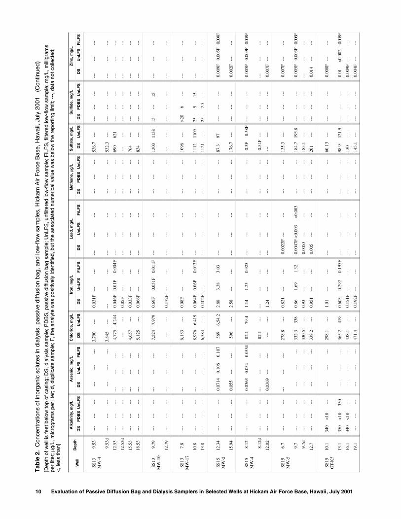
comparisons could not be made for some of the tested inorganic solutes because of limited data points. Of the inorganic solutes, chloride, sulfate, and iron had the most samples showing detections without laboratory qualifier flags and, therefore, are discussed in further detail in the following paragraphs.
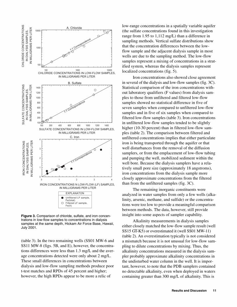
Chloride concentrations in the dialysis samples closely matched concentrations in most of the low-flow samples (fig. 3A). A modified t-test comparison showed that the dialysis-sample chloride concentrations were not statistically different from the low-flow chloride concen-trations in 8 of the 13 tested wells (table 3). In 2 of the remaining 5 wells (wells SS13 MW-10 and SS15 MW-4) insufficient data were available to run a t-test. However, the low RPDs (6 and 3 percent, respectively) between concentrations from the low-flow sample and dialysis sample deployed at the same depth indicated a close match. In one of the remaining wells (well SS10 MW-12), the data could not be analyzed using the t-test because they were not normally or natural log-normally distributed, and insufficient data were available to run a nonparametric test.
In most of the wells, the dialysis sampler data showed that chloride had a vertical concentration gradient or stratification (fig. 4D, E, G, H, I, J, K). In these wells, it is likely that mixing during low-flow pumping produces some degree of concentration devia-tion from the adjacent dialysis sampler.
The chloride concentrations in two wells (SS01 MW-2, and SS11 MW-8) showed a statistical differ-ence between the dialysis and low-flow samples (table 3, fig. 4A and F). In these wells, and in a well in which the chloride concentrations were not statistically analyzed (well SS01 MW-12; fig. 4E), the chloride concentrations in the low-flow samples were higher than in the dialysis samples. The close match in chlo-ride concentrations between sampling methods in other wells suggests that the differences in these wells may be attributed to well-specific factors rather than a dif-fusion-sampler deficiency. The fact that wells SS01 MW-12 and SS11 MW-8 also exhibited substantial dif-ferences in organic-compound concentrations between sampling methods (as will be discussed later in this report), suggests the possibility that the low-flow pumping induced movement of water into the well that did not flow to the well under nonpumping conditions.
Sulfate concentrations showed a close match between results from dialysis samples and low-flow samples (fig. 3B). Eight out of the ten wells statistically examined showed no statistical difference between the dialysis and low-flow sample sulfate concentrations
RESULTS AND DISCUSSION

Results and Discussion 9
Tab
le 2
. C
once
ntra
tions
of i
norg
anic
sol
utes
in d
ialy
sis,
pas
sive
diff
usio
n ba
g, a
nd lo
w-f
low
sam
ples
, Hic
kam
Air
For
ce B
ase,
Haw
aii,
July
200
1
[Dep
th o
f wel
l is
feet
bel
ow to
p of
cas
ing;
DS
, dia
lysi
s sa
mpl
e; P
DB
S, p
assi
ve d
iffus
ion
bag
sam
ple;
UnL
FS
, unf
ilter
ed lo
w-f
low
sam
ple;
FiL
FS
, filt
ered
low
-flo
w s
ampl
e; m
g/L,
mill
igra
ms
per
liter
; µg/
L, m
icro
gram
s pe
r lit
er; d
, dup
licat
e sa
mpl
e; F
, the
ana
lyte
was
pos
itive
ly id
entif
ied,
but
the
asso
ciat
ed n
umer
ical
val
ue w
as b
elow
the
repo
rtin
g lim
it; -
--, d
ata
not c
olle
cted
; <
, les
s th
an]
Wel
lD
epth
Alk
alin
ity,
mg
/LA
rsen
ic, m
g/L
Ch
lori
de,
mg
/LIr
on
, mg
/LL
ead
, mg
/LM
eth
ane,
µg
/LS
ulf
ate,
mg
/LS
ulf
ide,
mg
/LZ
inc,
mg
/L
DS
PD
BS
Un
LF
SD
SU
nL
FS
FiL
FS
DS
Un
LF
SD
SU
nL
FS
FiL
FS
DS
Un
LF
SF
iLF
SD
SP
DB
SU
nL
FS
DS
Un
LF
SD
SP
DB
SU
nL
FS
DS
Un
LF
SF
iLF
S
SS0
1M
W-2
16.0
4 -
-- -
-- -
-- -
-- -
-- -
--46
3 -
--0.
525
---
---
0.01
79 -
-- -
-- -
-- -
-- -
--32
.16
---
1 -
-- -
-- -
-- -
-- -
--
19.0
4 -
-- -
-- -
-- -
-- -
-- -
--47
850
3.5
0.34
50.
317
0.19
2F0.
0145
0.00
15F
0.00
12F
---
---
---
37.7
531
.29
1.5
0.6
0.2
---
---
---
22.0
4 -
-- -
-- -
-- -
-- -
-- -
--46
0 -
--0.
287
---
---
0.00
91 -
-- -
-- -
-- -
-- -
--42
.8 -
--2.
51
---
---
---
---
SS0
1M
W-6
16.5
3 -
-- -
-- -
-- -
-- -
-- -
--14
6.7
---
1.02
---
---
0.00
44F
---
---
---
---
---
1.95
---
---
---
---
0.00
4F -
-- -
--
19.5
3 -
-- -
-- -
-- -
-- -
-- -
--14
5.8
145.
41.
041.
161
0.00
4F -
--0.
0008
F -
-- -
-- -
--2.
081.
1 -
-- -
-- -
--0.
003F
---
---
22.5
3 -
-- -
-- -
-- -
-- -
-- -
--14
4 -
--1.
01 -
-- -
--0.
0036
F -
-- -
-- -
-- -
-- -
--1.
97 -
-- -
-- -
-- -
-- -
-- -
-- -
--
SS0
1M
W-8
10.2
---
---
---
---
---
---
73.7
69.5
0.73
0.81
10.
708
0.00
18F
<0.
0003
0.00
05F
4,10
05,
400
5,00
01.
652.
88 -
--0.
4 -
-- -
-- -
-- -
--
13.2
---
---
---
---
---
---
74.1
---
0.73
2 -
-- -
--0.
0018
F -
-- -
--4,
000
5,80
0 -
--0.
69F
---
---
0.3
<0.
1 -
-- -
-- -
--
13.2
d -
-- -
-- -
-- -
-- -
-- -
--71
.9 -
--0.
763
---
---
0.00
2F -
-- -
-- -
-- -
-- -
--0.
68F
---
---
---
---
---
---
---
16.2
---
---
---
---
---
---
70.5
---
0.73
5 -
-- -
--0.
0017
F -
-- -
-- -
-- -
-- -
--0.
89F
---
---
0.3
---
---
---
---
SS0
1M
W-1
116
.31
---
---
---
---
---
---
287.
3 -
--0.
109F
---
---
0.00
27F
---
---
---
---
---
20.9
3 -
-- -
-- -
-- -
--0.
045
---
---
19.3
150
0<
1037
5 -
-- -
-- -
--30
3.6
344
0.09
4F0.
132F
0.05
3F0.
0037
F<
0.00
3<
0.00
3 -
-- -
-- -
--21
.59
25.3
5 -
-- -
-- -
--0.
015
0.00
8F<
0.00
2
22.3
1 -
-- -
-- -
-- -
-- -
-- -
--35
8.8
---
0.11
9F -
-- -
--0.
005
---
---
---
---
---
51.0
9 -
-- -
-- -
-- -
--0.
012
---
---
SS0
1M
W-1
213
.38
---
---
---
---
---
---
282
---
0.23
4 -
-- -
--0.
0047
F -
-- -
-- -
-- -
-- -
--6.
38 -
-- -
-- -
-- -
--0.
004F
---
---
16.3
8 -
-- -
-- -
-- -
-- -
-- -
--35
6.6
391
0.32
50.
132F
0.08
7F0.
0036
F<
0.00
03<
0.00
033,
900
---
3,80
03.
334.
2 -
-- -
-- -
--0.
007F
<0.
002
<0.
002
16.3
8d -
-- -
-- -
-- -
-- -
-- -
-- -
-- -
--0.
272
---
---
0.00
34F
---
---
---
---
---
---
---
---
---
---
0.00
6F -
-- -
--
19.3
8 -
-- -
-- -
-- -
-- -
-- -
--35
4 -
--0.
246
---
---
0.00
18F
---
---
---
---
---
4.32
---
---
---
---
0.00
3F -
-- -
--
---
---
---
---
---
---
357.
2 -
-- -
-- -
-- -
-- -
-- -
-- -
-- -
-- -
-- -
--4.
39 -
-- -
-- -
-- -
-- -
-- -
-- -
--
22.3
8 -
-- -
-- -
-- -
-- -
-- -
--35
5.6
---
0.24
2 -
-- -
--0.
0032
F -
-- -
-- -
-- -
-- -
--3.
74 -
-- -
-- -
-- -
--0.
006F
---
---
SS1
1M
W-8
9.69
---
---
---
---
---
---
1,20
11,
490
0.80
10.
840.
592
0.00
4F0.
0006
F0.
0009
F -
-- -
-- -
--2.
133.
360.
150.
10.
10.
013
0.00
4F<
0.00
2
12.6
9 -
-- -
-- -
-- -
-- -
-- -
--1,
226
---
0.93
9 -
-- -
--0.
0042
F -
-- -
-- -
-- -
-- -
--2
---
<0.
1 -
-- -
--0.
004F
---
---
10 Evaluation of Passive Diffusion Bag and Dialysis Samplers in Selected Wells at Hickam Air Force Base, Hawaii, July 2001
SS13
MW
-49.
53 -
-- -
-- -
-- -
-- -
-- -
--3,
790
---
0.03
1F -
-- -
-- -
-- -
-- -
-- -
-- -
-- -
--53
6.7
---
---
---
---
---
---
---
9.53
d -
-- -
-- -
-- -
-- -
-- -
--3,
845
---
---
---
---
---
---
---
---
---
---
532.
3 -
-- -
-- -
-- -
-- -
-- -
-- -
--
12.5
3 -
-- -
-- -
-- -
-- -
-- -
--4,
775
4,24
40.
046F
0.01
F0.
004F
---
---
---
---
---
---
690
621
---
---
---
---
---
---
12.5
3d -
-- -
-- -
-- -
-- -
-- -
-- -
-- -
--0.
05F
---
---
---
---
---
---
---
---
---
---
---
---
---
---
---
---
15.5
3 -
-- -
-- -
-- -
-- -
-- -
--4,
657
---
0.03
3F -
-- -
-- -
-- -
-- -
-- -
-- -
-- -
--76
4 -
-- -
-- -
-- -
-- -
-- -
-- -
--
18.5
3 -
-- -
-- -
-- -
-- -
-- -
--5,
125
---
0.06
6F -
-- -
-- -
-- -
-- -
-- -
-- -
-- -
--83
4 -
-- -
-- -
-- -
-- -
-- -
-- -
--
SS13
MW
-10
9.79
---
---
---
---
---
---
7,52
47,
979
0.69
F0.
051F
0.01
1F -
-- -
-- -
-- -
-- -
-- -
--13
0311
3815
---
15 -
-- -
-- -
--
12.7
9 -
-- -
-- -
-- -
-- -
-- -
-- -
-- -
--0.
172F
---
---
---
---
---
---
---
---
---
---
---
---
---
---
---
---
SS13
MW
-17
7.8
---
---
---
---
---
---
6,18
3 -
--0.
08F
---
---
---
---
---
---
---
---
1096
---
>20
6 -
-- -
-- -
-- -
--
10.8
---
---
---
---
---
---
8,97
66,
419
0.06
4F0.
06F
0.01
3F -
-- -
-- -
-- -
-- -
-- -
--11
1211
0925
515
---
---
---
13.8
---
---
---
---
---
---
6,58
4 -
--0.
102F
---
---
---
---
---
---
---
---
1121
---
257.
5 -
-- -
-- -
-- -
--
SS15
MW
-212
.34
---
---
---
0.07
140.
106
0.10
756
96,
54.2
2.88
3.38
3.03
---
---
---
---
---
---
87.3
97 -
-- -
-- -
--0.
009F
0.00
5F0.
004F
15.9
4 -
-- -
-- -
--0.
055
---
---
596
---
2.58
---
---
---
---
---
---
---
---
176.
7 -
-- -
-- -
-- -
--0.
002F
---
---
SS15
MW
-48.
12 -
-- -
-- -
--0.
0363
0.03
40.
0334
82.1
79.4
1.14
1.25
0.92
5 -
-- -
-- -
-- -
-- -
-- -
--0.
5F0.
58F
---
---
---
0.00
5F0.
009F
0.00
3F
8.12
d -
-- -
-- -
-- -
-- -
-- -
--82
.1 -
-- -
-- -
-- -
-- -
-- -
-- -
-- -
-- -
-- -
--0.
54F
---
---
---
---
---
---
---
12.0
2 -
-- -
-- -
--0.
0369
---
---
---
---
1.24
---
---
---
---
---
---
---
---
---
---
---
---
---
0.00
7F -
-- -
--
SS15
MW
-56.
7 -
-- -
-- -
-- -
-- -
-- -
--27
8.8
---
0.82
1 -
-- -
--0.
0022
F -
-- -
-- -
-- -
-- -
--13
5.3
---
---
---
---
0.00
7F -
-- -
--
9.7
---
---
---
---
---
---
332.
333
80.
861.
691.
320.
0047
F<
0.00
3<0
.003
---
---
---
184.
719
3.8
---
---
---
0.00
5F0.
003F
0.00
6F
9.7d
---
---
---
---
---
---
330.
5 -
--0.
93 -
-- -
--0.
0053
---
---
---
---
---
185.
1 -
-- -
-- -
-- -
-- -
-- -
-- -
--
12.7
---
---
---
---
---
---
338.
2 -
--0.
951
---
---
0.00
5 -
-- -
-- -
-- -
-- -
--20
1 -
-- -
-- -
-- -
--0.
014
---
---
SS15
GT-
K5
10.1
340
<10
---
---
---
---
298.
1 -
--1.
01 -
-- -
-- -
-- -
-- -
-- -
-- -
-- -
--60
.13
---
---
---
---
0.00
8F -
-- -
--
13.1
350
<10
350
---
---
---
365.
241
90.
603
0.29
20.
195F
---
---
---
---
---
---
98.9
121.
9 -
-- -
-- -
--0.
01<0
.002
0.00
3F
16.1
340
<10
---
---
---
---
438.
1 -
--0.
151F
---
---
---
---
---
---
---
---
130
---
---
---
---
0.00
9F -
-- -
--
19.1
---
---
---
---
---
---
471.
4 -
--0.
192F
---
---
---
---
---
---
---
---
145.
1 -
-- -
-- -
-- -
--0.
004F
---
---
Tab
le 2
. C
once
ntra
tions
of i
norg
anic
sol
utes
in d
ialy
sis,
pas
sive
diff
usio
n ba
g, a
nd lo
w-f
low
sam
ples
, Hic
kam
Air
For
ce B
ase,
Haw
aii,
July
200
1 (
Con
tinue
d)
[Dep
th o
f wel
l is
feet
bel
ow to
p of
cas
ing;
DS
, dia
lysi
s sa
mpl
e; P
DB
S, p
assi
ve d
iffus
ion
bag
sam
ple;
UnL
FS
, unf
ilter
ed lo
w-f
low
sam
ple;
FiL
FS
, filt
ered
low
-flo
w s
ampl
e; m
g/L,
mill
igra
ms
per
liter
; µg/
L, m
icro
gram
s pe
r lit
er; d
, dup
licat
e sa
mpl
e; F
, the
ana
lyte
was
pos
itive
ly id
entif
ied,
but
the
asso
ciat
ed n
umer
ical
val
ue w
as b
elow
the
repo
rtin
g lim
it; -
--, d
ata
not c
olle
cted
; <
, les
s th
an]
Wel
lD
epth
Alk
alin
ity,
mg
/LA
rsen
ic, m
g/L
Ch
lori
de,
mg
/LIr
on
, mg
/LL
ead
, mg
/LM
eth
ane,
µg
/LS
ulf
ate,
mg
/LS
ulf
ide,
mg
/LZ
inc,
mg
/L
DS
PD
BS
Un
LF
SD
SU
nL
FS
FiL
FS
DS
Un
LF
SD
SU
nL
FS
FiL
FS
DS
Un
LF
SF
iLF
SD
SP
DB
SU
nL
FS
DS
Un
LF
SD
SP
DB
SU
nL
FS
DS
Un
LF
SF
iLF
S
Results and Discussion 11
A. Chloride
CHLORIDE CONCENTRATIONS IN LOW-FLOW SAMPLES,IN MILLIGRAMS PER LITER
100 1000 10000
CH
LOR
IDE
CO
NC
ENTR
ATIO
NS
IN D
IALY
SIS
SAM
PLES
,IN
MIL
LIG
RAM
S PE
R L
ITER
100
1000
10000
1:1 Correspondence
B. Sulfate
SULFATE CONCENTRATIONS IN LOW-FLOW SAMPLES,IN MILLIGRAMS PER LITER
200100 400 600 800 1000 1200 1400SULF
ATE
CO
NC
ENTR
ATIO
NS
IN D
IALY
SIS
SAM
PLES
,IN
MIL
LIG
RAM
S PE
R L
ITER
200
400
100
600
800
1000
1200
1400
1:1 Correspondence
C. Iron
IRON CONCENTRATIONS N LOW-FLOW (LF) SAMPLES, IN MILLIGRAMS PER LITER
0 1 2 3 4
IRO
N C
ON
CEN
TRAT
ION
S IN
DIA
LYSI
S SA
MPL
ES,
IN M
ILLI
GR
AMS
PER
LIT
ER
0
1
2
3
4
Unfiltered LF sample, Fe(total)Filtered LF sample,Fe(II)
1:1 Correspondence
EXPLANATON
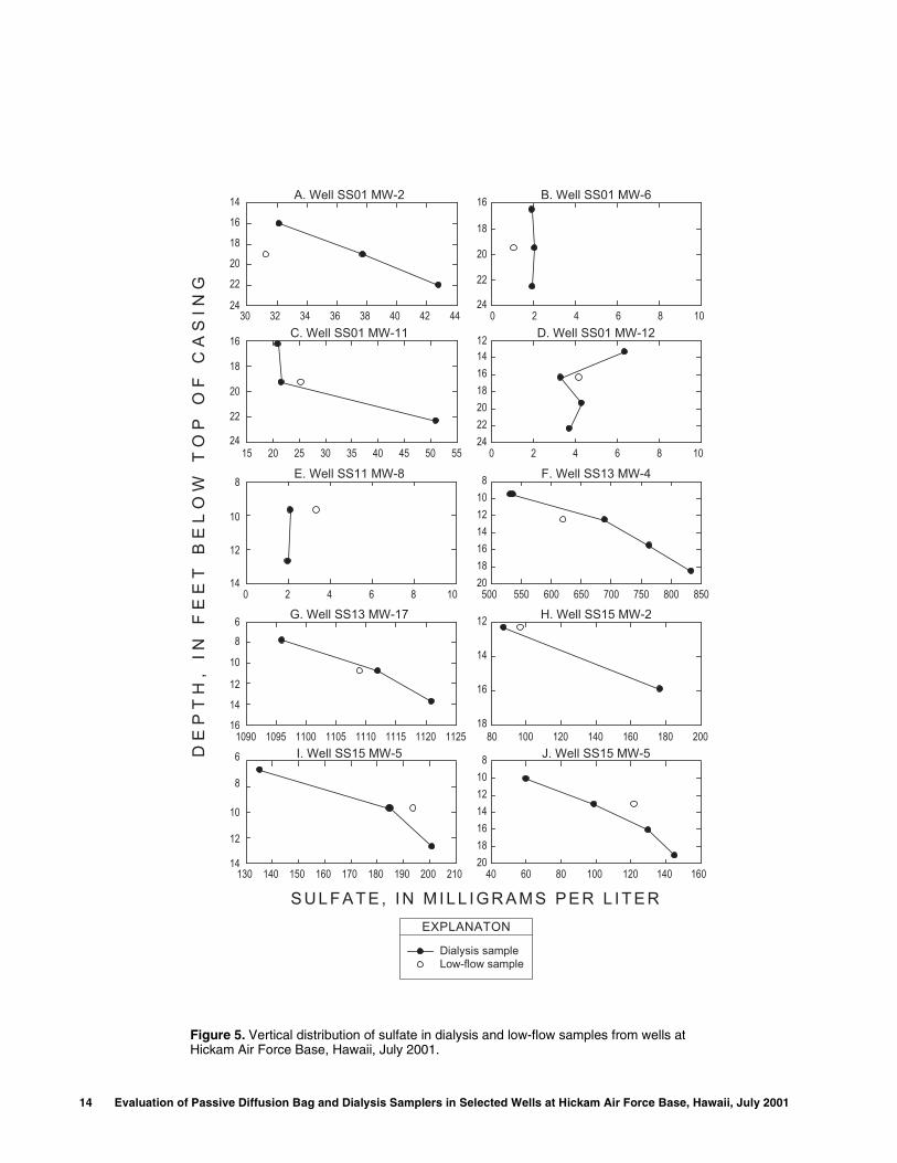
(table 3). In the two remaining wells (SS01 MW-6 and SS11 MW-8 (figs. 5B, and E), however, the concentra-tions differences were less than 1.3 mg/L and the aver-age concentrations detected were only about 2 mg/L. These small differences in concentrations between dialysis and low-flow sampling methods produce poor t-test matches and RPDs of 45 percent and higher; however, the high RPDs appear to be more a relic of
low-range concentrations in a spatially variable aquifer (the sulfate concentrations found in this investigation range from 1.95 to 1,112 mg/L) than a difference in sampling methods. Vertical sulfate distributions show that the concentration differences between the low-flow sample and the adjacent dialysis sample in most wells are due to the sampling method. The low-flow samples represent a mixing of concentrations in a strat-ified system, whereas the dialysis samples represent localized concentrations (fig. 5).
Iron concentrations also showed close agreement in several of the dialysis and low-flow samples (fig. 3C). Statistical comparison of the iron concentrations with-out laboratory qualifiers (F values) from dialysis sam-ples to those from unfiltered and filtered low-flow samples showed no statistical difference in five of seven samples when compared to unfiltered low-flow samples and in five of six samples when compared to filtered low-flow samples (table 3). Iron concentrations in unfiltered low-flow samples tended to be slightly higher (10-30 percent) than in filtered low-flow sam-ples (table 2). The comparison between filtered and unfiltered concentrations implies that either particulate iron is being transported through the aquifer or that well disturbances from the removal of the diffusion samplers, or from the emplacement of low-flow tubing and pumping the well, mobilized sediment within the well bore. Because the dialysis samplers have a rela-tively small pore size (approximately 18 angstroms), iron concentrations from the dialysis sample more closely approximate concentrations from the filtered than from the unfiltered samples (fig. 3C).
The remaining inorganic constituents were analyzed in water samples from only a few wells (alka-linity, arsenic, methane, and sulfide) or the concentra-tions were too low to provide a meaningful comparison between methods. The data, however, still provide insight into some aspects of sampler capability.
Alkalinity measurements in dialysis samples either closely matched the low-flow sample result (well SS15 GT-K5) or overestimated it (well SS01 MW-11) (table 2). An overestimation typically is not considered a mismatch because it is not unusual for low-flow sam-pling to dilute concentrations by mixing. Thus, the alkalinity concentrations measured in the dialysis sam-pler probably approximate alkalinity concentrations in the undisturbed water column in the well. It is impor-tant, however, to note that the PDB samplers contained no detectable alkalinity, even when deployed in waters containing greater than 300 mg/L of alkalinity. This is
Figure 3. Comparison of chloride, sulfate, and iron concen-trations in low-flow samples to concentrations in dialysis samples at the same depth, Hickam Air Force Base, Hawaii, July 2001.

12 Evaluation of Passive Diffusion Bag and Dialysis Samplers in Selected Wells at Hickam Air Force Base, Hawaii, July 2001
Tab
le 3
. S
tatis
tical
com
paris
on o
f chl
orid
e, s
ulfa
te, a
nd ir
on c
once
ntra
tions
in d
ialy
sis
and
low
-flo
w s
ampl
es, H
icka
m A
ir F
orce
Bas
e, H
awai
i, Ju
ly 2
001
[t criti
cal,
criti
cal v
alue
of t
-tes
t t s
tatis
tic; m
g/L,
mill
igra
ms
per
liter
, t',
calc
ulat
ed t
stat
istic
from
mod
ified
t-te
st; -
--, n
ot c
alcu
late
d be
caus
e of
qua
lifie
d or
insu
ffici
ent d
ata.
Chl
orid
e da
ta fr
om
wel
l SS
01 M
W-1
2 w
ere
not s
tatis
tical
ly e
valu
ated
, bec
ause
the
data
wer
e no
t nor
mal
ly o
r na
tura
l log
-nor
mal
ly d
istr
ibut
ed a
nd th
ere
wer
e no
t eno
ugh
data
poi
nts
for
a no
npar
amet
ric
com
paris
on o
f gro
ups]
Wel
l
Nu
mb
er
of
dia
lysi
s-
sam
ple
r d
epth
s
Deg
rees
o
f fr
eed
om
t crit
ical
Ch
lori
de
Su
lfat
eIr
on
Co
nce
ntr
atio
n
in d
ialy
sis
sam
ple
s
Co
mp
aris
on
of
dia
lysi
s to
low
-flo
w s
amp
le
con
cen
trat
ion
s
Co
nce
ntr
atio
n
in d
ialy
sis
sam
ple
s
Co
mp
aris
on
of
dia
lysi
s to
low
-flo
w s
amp
le
con
cen
trat
ion
s
Co
nce
ntr
atio
n
in d
ialy
sis
sam
ple
s
Co
mp
aris
on
of
dia
lysi
s (f
erro
us
iro
n)
to u
nfi
lter
ed
low
-flo
w s
amp
le
(to
tal i
ron
) co
nce
ntr
atio
ns
Co
mp
aris
on
of
dia
lysi
s to
filt
ered
lo
w-f
low
sam
ple
(f
erro
us
iro
n)
con
cen
trat
ion
s
Mea
n
(m
g/L
)
Sta
nd
ard
d
evia
tio
n
(mg
/L)
t'A
re t
he
two
m
eth
od
s st
atis
tica
lly
dif
fere
nt?
Mea
n
(m
g/L
)
Sta
nd
ard
d
evia
tio
n
(mg
/L)
t'A
re t
he
two
m
eth
od
s st
atis
tica
lly
dif
fere
nt?
Mea
n
(m
g/L
)
Sta
nd
ard
d
evia
tio
n
(mg
/L)
t'A
re t
he
two
m
eth
od
s st
atis
tica
lly
dif
fere
nt?
t'A
re t
he
two
m
eth
od
s st
atis
tica
lly
dif
fere
nt?
SS01
M
W-2
32
2.92
467
9.64
3.84
yes
35.6
5.3
1.94
no0.
40.
120.
604
no -
-- -
--
SS01
M
W-6
32
2.92
146
1.38
-5.3
7no
20.
0722
yes
10.
024.
97ye
s-6
.425
no
SS01
M
W-8
32
2.92
721.
680.
084
no -
-- -
-- -
-- -
--0.
70.
011.
66no
-5.2
1no
SS01
M
W-1
13
22.
9231
734
.50.
791
no31
.217
0.56
3no
---
---
---
---
---
---
SS01
M
W-1
24
32.
3533
737
---
---
4.45
1.4
0.30
9no
0.3
0.04
---
---
---
---
SS11
M
W-8
21
6.31
41,
214
17.7
18.5
yes
2.07
0.09
19.4
yes
0.8
0.10
-0.5
39no
3.34
no
SS13
M
W-4
43
2.35
4,59
455
40.
802
no70
512
81.
22no
---
---
---
---
---
---
SS13
M
W-1
01
0 -
--7,
524
---
---
---
1,30
3 -
-- -
-- -
-- -
-- -
-- -
-- -
-- -
-- -
--
SS13
M
W-1
73
22.
927,
248
1,51
00.
729
no11
1012
-1.4
3no
---
---
---
---
---
---
SS15
M
W-2
21
6.31
458
319
.13.
86no
132
630.
761
no2.
70.
212.
53no
0.38
4no
SS15
M
W-4
10
---
82 -
-- -
-- -
-- -
-- -
-- -
-- -
--1.
20.
07-0
.8no
3.82
no
SS15
M
W-5
32
2.92
316
32.5
0.57
3no
174
341.
08no
0.9
0.07
22ye
s10
.7ye
s
SS15
G
T-K
54
32.
353
393
77.4
0.34
2no
109
370.
647
no -
-- -
-- -
-- -
-- -
-- -
--

Results and Discussion 13
Figure 4. Vertical distribution of chloride in dialysis and low-flow samples from wells at Hickam Air Force Base, Hawaii, July 2001.
5000 6000 7000 8000 9000 10000
6
8
10
12
14
16
200 250 300 350 400
1012141618202224
0 20 40 60 80 100
8
10
12
14
16
18
250 300 350 400 450 500
8101214161820
260 280 300 320 340
4
6
8
10
12
14
3000 3500 4000 4500 5000 5500 6000
8101214161820
80 100 120 140 160 180
14
16
18
20
22
24
400 450 500 550
14
16
18
20
22
24
260 280 300 320 340 360 380 400
14
16
18
20
22
24
1000 1100 1200 1300 1400 1500 1600
8
10
12
14
16
18
500 550 600 650 700
10
12
14
16
18
Dialysis sampleLow-flow sample
CHLORIDE, IN MILLIGRAMS PER L ITER
DE
PT
H,
I
N
FE
ET
B
EL
OW
T
OP
O
F
CA
SI
NG
EXPLANATON
A. Well SS01 MW-2
C. Well SS01 MW-8
B. Well SS01 MW-6
D. Well SS01 MW-11
E. Well SS01 MW-12 F. Well SS11 MW-8
G. Well SS13 MW04 H. Well SS13MW-17
I. Well SS15 MW-2
K. Well SS15 GT-K5
J. Well SS15 MW-5
14 Evaluation of Passive Diffusion Bag and Dialysis Samplers in Selected Wells at Hickam Air Force Base, Hawaii, July 2001
15 20 25 30 35 40 45 50 55
16
18
20
22
24
1090 1095 1100 1105 1110 1115 1120 1125
6
8
10
10
16
30 32 34 36 38 40 42 44
14
16
18
20
22
24
0 2 4 6 8 10
12141618202224
500 550 600 650 700 750 800 850
8101214161820
0 2 4 6 8 10
16
18
20
22
24
0 2 4 6 8 10
8
10
12
14
40 60 80 100 120 140 160
8101214161820
80 100 120 140 160 180 200
12
14
16
18
130 140 150 160 170 180 190 200 210
6
8
12
12
14
14
DE
PT
H,
IN F
EE
T B
EL
OW
TO
P O
F C
AS
ING
A. Well SS01 MW-2 B. Well SS01 MW-6
C. Well SS01 MW-11 D. Well SS01 MW-12
E. Well SS11 MW-8 F. Well SS13 MW-4
G. Well SS13 MW-17 H. Well SS15 MW-2
I. Well SS15 MW-5 J. Well SS15 MW-5
Dialysis sampleLow-flow sample
EXPLANATON
S U L F A T E , I N M I L L I G R A M S P E R L I T E R
Figure 5. Vertical distribution of sulfate in dialysis and low-flow samples from wells at Hickam Air Force Base, Hawaii, July 2001.

Results and Discussion 15
important, because one difficulty in obtaining VOC samples from limestone aquifers is that addition of an acid preservative to high-alkalinity water can cause effervescence due to the neutralization reaction. The effervescence then can volatilize VOCs in the sample, rendering the sample unreliable. A typical response to this situation is to collect another sample and ship it to the laboratory unpreserved, which decreases the hold-ing time from 14 to 7 days (U.S. Environmental Protec-tion Agency, 1992). The fact that the LDPE membrane of PDB samplers differentiates against alkalinity and has been shown to effectively transmit VOC concentra-tions means that VOC samples can be collected from alkaline waters and preserved with acid in a nonalka-line matrix without VOC loss by effervescence. Addi-tional investigation is ongoing to determine whether this applies to other sites.
A comparison of arsenic concentrations between sampling methodologies was conducted in only two wells because of arsenic’s limited distribution. The number of data points was too limited for an adequate evaluation of the dialysis sampler’s ability to accu-rately sample arsenic in ground water. The similarity between arsenic concentrations in dialysis samples and both the unfiltered and filtered low-flow samples in well SS15 MW-4, however, implies that the dialysis samplers are capable of accurately collecting arsenic samples (table 2).
A larger vertical variation of arsenic concentra-tion was observed in well SS15 MW-2 (26 RPD change in arsenic concentrations over a 3.6-ft vertical interval) than at well SS15 MW-4 (no significant variation) (table 2). Arsenic concentrations in dialysis samples from well SS15 MW-2 underestimated low-flow sample concentrations by about 40 RPD. The cause of the difference is unknown because of the limited data set.
Lead and zinc concentrations also were exam-ined in dialysis and low-flow samples (table 2). In both cases, the concentrations were predominantly below the reporting limit. Therefore, the detected concentra-tions were too low to adequately evaluate dialysis sampler ability to accurately sample these constituents in ground water.
Similarly, only limited data are available for methane and sulfide comparisons (table 2). At two wells, the methane concentrations showed a relatively close match (about 3 to 20 RPD) between same-depth dialy-sis and low-flow samples, implying that the dialysis samples adequately represented ground-water methane concentrations in those wells. In one sample, the PDB
methane concentration differed from the same-depth low-flow sample concentration by only 8 RPD, imply-ing that the PDB samplers also are capable of provid-ing accurate methane samples. Although sulfide concentrations in the dialysis samples varied from concentrations in low-flow samples by a broad range, the sulfide concentrations in the dialysis samples were all equal to or greater than the concentrations in the low-flow samples. In general, when sampling gases, it is easier to lose than to gain concentrations; therefore, the data imply that dialysis samples adequately represented sulfide concentrations.
Mercury (not shown in table 2) was analyzed but was not found (detection limit 1 µg/L) at site SS13 in ground water from well SS13 MW-10 in dialysis samplers from two sampling horizons and in a filtered and unfiltered low-flow sample. Copper (not shown in table 2) also was measured in all three wells at site SS13 but was not found (detection limit 1 µg/L) in low-flow and dialysis samples. A possible exception was well SS13 MW-10, where copper was detected at 6 µg/L in the dialysis sample from 12.79 ft below the top of casing but was not detected in a shallower low-flow sample from 9.79 ft below top of casing. The copper result was “F value,” which means that the analyte was positively identified, but the associated numerical value was below the reporting limit.
Volatile Organic Compounds
VOC concentrations were compared between dialysis samples, PDB samples, and low-flow samples (table 4). In general, the comparisons in concentrations between the two different types of diffusion samples showed a relatively close correspondence. At concen-trations less than 6 µg/L, the average concentration difference between dialysis and PDB samples for indi-vidual VOCs was 0.8 µg/L (range of 0.1 to 2.4 µg/L). Concentrations are used in this comparison because RPD calculations are overly sensitive at low concen-trations. At concentrations greater than 6 µg/L, the average RPD for individual VOCs was 16.7 percent (range of 0.3 to 45.1 percent) between dialysis and PDB samplers from corresponding depths. The rela-tively close match in concentrations from the two different types of diffusion membranes at most loca-tions indicates that the concentrations accurately repre-sent concentrations of the tested constituents in water contacting the samplers.

16 Evaluation of Passive Diffusion Bag and Dialysis Samplers in Selected Wells at Hickam Air Force Base, Hawaii, July 2001
Table 4. Concentrations of organic solutes in dialysis, passive diffusion bag, and low-flow samples, Hickam Air Force Base, Hawaii, July 2001
[Depth of well is in feet below top of casing; DS, dialysis sample; PDBS, passive diffusion bag sample; UnLFS unfiltered low-flow sample; RPD, relative percent difference; µg/L, micrograms per liter; *, difference in µg/L; F, the analyte was positively identified, but the associated numerical value was below the reporting limit; J, the analyte was positively identified, the quantitation is an estimate, because it is outside the calibration limits or other Air Force Center for Environmental Excellence acceptance criteria were not met; ---, data not collected or not applicable; >, greater than; <, less than]
Benzene, µg/L Toluene, µg/L Ethylbenzene, µg/L
Well Depth DS PDBS UnLFS
Difference between
dialysis and PDB samples
as RPD, in percent, for
concentrations >10 µg/L or as
µg/L* for concentrations
<10 µg/L
DS PDBS UnLFS
Difference between
dialysis and PDB samples
as RPD, in percent, for
concentrations >10 µg/L or as
µg/L* for concentrations
<10 µg/L
DS PDBS UnLFS
Difference between
dialysis and PDB samples
as RPD, in percent, for
concentrations >10 µg/L or as
µg/L* for concentrations
<10 µg/L
SS01 MW-2
16.04 --- 24.31 --- --- --- 0.32F --- --- --- 1.31 --- ---
19.04 5.7 7.71 26 0.21* <0.11 <0.11 0.26F --- 0.35F 0.46F 0.84 ---22.04 --- 3.32 --- --- --- <0.11 --- --- --- 0.27F --- ---
SS01 MW-6
16.53 --- <0.08 --- --- --- 0.19F --- --- --- 0.29F --- ---
19.53 <0.01 <0.08 <0.08 --- --- 0.17F --- --- <0.14 0.25F <0.08 ---22.53 --- 0.39F --- --- --- 0.58F --- --- --- 0.81 --- ---
SS01 MW-8
10.2 --- 3.28 4.73 --- --- 0.15F 0.28F --- 1.46 3.77 ---
10.2 --- 2.91 --- --- --- <0.14 --- --- --- 1.21 --- ---13.2 4.68 5.05 --- 0.37* 0.18F 0.18F --- --- 2.47 3.03 --- 0.56*13.2 --- 4.82 --- 0.14* --- 0.17F --- --- --- 2.82 --- 0.35*16.2 --- 5.05 --- --- --- 0.17F --- --- --- 3.1 --- ---16.2 --- 4.97 --- --- --- 0.17F --- --- --- 3.09 --- ---
SS01 MW-11
16.31 --- 0.47 --- --- --- <0.14 --- --- --- 0.54F --- ---
19.31 0.37F 0.47 2.83 --- 0.22F 0.2F <0.1 --- <0.14 0.34F 1.52 ---22.31 --- 0.89 --- --- --- 0.78F --- --- --- <0.14 --- ---
SS01 MW-12
13.38 350.5 --- --- --- 240.4 --- --- --- 332.2 --- ---
16.38 833.7 758.9 973.6 9 441.4 495.6 172.4 12 566.6 528.4 1094 716.38 827.6 801.6 --- 3 406.4 528.9 --- 26 525.4 613.2 --- 1519.38 --- 904.1 --- --- --- 610.1 --- --- --- 631.2 --- ---22.38 --- 855.9 --- --- --- 537 --- --- --- 541.5 --- ---
SS11 MW-8
9.69 627.8 806.3 109.8 25 0.38F 0.44F <1.4 --- 169.1 267.6 <1.4 45
12.69 --- 889.7 --- --- --- 0.45F --- --- --- 272.5 --- ---
SS13 MW-4
9.53 --- 0.11F --- --- --- <0.14 --- --- --- <0.14 --- ---
12.53 <0.1 <0.1 0.08F --- 0.21F <0.14 <0.1 --- <0.14 <0.14 <0.08 ---15.53 --- <0.1 --- --- --- <0.14 --- --- --- <0.14 --- ---18.53 --- <0.1 --- --- --- <0.14 --- --- --- <0.14 --- ---
SS13 MW-10
9.79 <0.1 <0.1 <0.08 --- <0.14 <0.14 <0.1 --- <0.14 <0.14 <0.08 ---
12.79 --- <0.1 --- --- --- <0.14 --- --- --- <0.14 --- ---
SS13 MW-17
7.8 --- 0.23F --- --- --- <0.14 --- --- --- 0.15F --- ---
10.8 <0.1 <0.1 <0.08 --- 0.18F <0.14 <0.1 --- <0.14 <0.14 <0.08 ---13.8 --- <0.1 --- --- --- <0.14 --- --- --- <0.14 --- ---
SS15 MW-2
12.34 <0.14 <0.14 --- --- <0.11 <0.11 <0.14 --- <0.12 <0.12 <0.14 ---
SS15
MW-48.12 <0.14 <0.14 <0.1 --- <0.11 <0.11 <0.14 --- <0.12 <0.12 <0.12 ---
SS15 MW-5
6.7 --- <0.1 --- --- --- <0.14 --- --- --- <0.14 --- ---
9.7 <0.1 <0.1 <0.08 --- <0.14 <0.14 <0.14 --- <0.14 <0.14 <0.08 ---12.7 --- <0.1 --- --- --- <0.14 --- --- --- --- --- ---
SS15 GT-K5
10.1 --- <0.1 --- --- --- <0.14 --- --- --- <0.14 --- ---
13.1 <0.1 <0.1 0.46 --- <0.14 <0.14 <0.14 --- <0.14 <0.14 0.14F ---13.1 --- <0.1 --- --- --- <0.14 --- --- --- <0.14 --- ---16.1 --- <0.1 --- --- --- <0.14 --- --- --- <0.14 --- ---19.1 --- <0.1 --- --- --- <0.14 --- --- --- <0.14 --- ---

Results and Discussion 17
Table 4. Concentrations of organic solutes in dialysis, passive diffusion bag, and low-flow samples, Hickam Air Force Base, Hawaii, July 2001 (Continued)
[Depth of well is in feet below top of casing; DS, dialysis sample; PDBS, passive diffusion bag sample; UnLFS unfiltered low-flow sample; RPD, relative percent difference; µg/L, micrograms per liter; *, difference in µg/L; F, the analyte was positively identified, but the associated numerical value was below the reporting limit; J, the analyte was positively identified, the quantitation is an estimate, because it is outside the calibration limits or other Air Force Center for Environmental Excellence acceptance criteria were not met; ---, data not collected or not applicable; >, greater than; <, less than]
o-Xylene, µg/L m,p-Xylene, µg/L Isopropylbenzene, µg/L
Well Depth DS PDBS UnLFS
Difference between
dialysis and PDB samples
as RPD, in percent, for
concentrations >10 µg/L or as
µg/L* for concentrations
<10 µg/L
DS PDBS UnLFS
Difference between
dialysis and PDB samples
as RPD, in percent, for
concentrations >10 µg/L or as
µg/L* for concentrations
<10 µg/L
DS PDBS UnLFS
Difference between
dialysis and PDB samples
as RPD, in percent, for
concentrations >10 µg/L or as
µg/L* for concentrations
<10 µg/L
SS01 MW-2
16.04 --- <0.07 --- --- --- <0.13 --- --- --- 2.7 --- ---
19.04 <0.13 <0.13 <0.07 --- <0.23 <0.23 0.15F --- 1.01 1.21 4.06 0.2*22.04 --- <0.13 --- --- --- <0.23 --- --- --- 0.85 --- ---
SS01 MW-6
16.53 --- 0.14F --- --- --- 0.42F --- --- --- 7.53 --- ---
19.53 <0.07 0.13F <0.11 --- <0.13 0.35F <0.2 --- 6.97 7.56 4.32 0.59*22.53 --- 0.44F --- --- --- 1.23 --- --- --- 6.07 --- ---
SS01 MW-8
10.2 --- <0.13 0.09F --- 1.26 3.19 --- --- 1.88 6.5 ---
10.2 --- <0.07 --- --- --- 1.04 --- --- --- 1.57 --- ---13.2 <0.13 <0.13 --- --- 1.63 2.05 --- --- 3.43 3.94 --- 0.51*13.2 --- <0.07 --- --- --- 1.92 --- --- --- 3.79 --- 0.36*16.2 --- <0.13 --- --- --- 1.91 --- --- --- 3.53 --- ---16.2 --- <0.07 --- --- --- 1.9 --- --- --- 3.7 --- ---
SS01 MW-11
16.31 --- <0.07 --- --- --- <0.13 --- --- --- 1.72 --- ---
19.31 <0.07 <0.07 <0.11 --- <0.13 <0.13 <0.2 --- 1.07 2.2 7.47 0.23*22.31 --- <0.07 --- --- --- <0.13 --- --- --- <0.06 --- ---
SS01 MW-12
13.38 --- 211.8 --- --- --- 635.5 --- --- --- 20.74 --- ---
16.38 238.8 261.3J 57.4 --- 669.9 722.2 141.3 8 21.48 21.12 40.54 216.38 217.5 331J --- --- 624.5 837.7 --- 29 16.03 21.32 --- 2819.38 --- 330.3 --- --- --- 840.5 --- --- --- 17.96 --- ---22.38 --- 279.2 --- --- --- 716 --- --- --- 19.7 --- ---
SS11 MW-8
9.69 7.06 7.31 4.88J 0.25* 74.4 82.8 3.4F --- 16.13 19.64 <0.6 20
12.69 --- 6.03 --- --- --- 97.4 --- --- --- 18.43 --- ---
SS13 MW-4
9.53 --- 0.1F --- --- --- 0.18F --- --- --- 5.93 --- ---
12.53 <0.07 0.08F <0.11 --- <0.13 0.19F <0.2 --- 2.07 1.61 2.31 0.46*15.53 --- <0.07 --- --- --- 0.16F --- --- --- 1.07 --- ---18.53 --- <0.07 --- --- --- 0.13F --- --- --- 0.4F --- ---
SS13 MW-10
9.79 <0.07 <0.07 <0.11 --- <0.12 <0.13 <0.2 --- <0.6 <0.6 <0.1 ---
12.79 --- <0.07 --- --- --- <0.13 --- --- --- <0.6 --- ---
SS13 MW-17
7.8 --- <0.07 --- --- --- <0.13 --- --- --- <0.6 --- ---
10.8 <0.07 <0.07 <0.11 --- <0.13 <0.13 <0.2 --- <0.6 <0.6 <0.1 ---13.8 --- <0.07 --- --- --- <0.13 --- --- --- <0.6 --- ---
SS15 MW-2
12.34 <0.13 <0.13 <0.07 --- <0.23 <0.23 <0.13 --- 0.19F 0.24F 0.34F ---
SS15 MW-4
8.12 <0.13 <0.07 <0.07 --- <0.23 <0.23 <0.13 --- 3.75 5.61 <0.06 1.86*
SS15 MW-5
6.7 --- <0.07 --- --- --- <0.13 --- --- --- <0.06 --- ---
9.7 <0.07 <0.07 <0.11 --- <0.13 <0.13 <0.2 --- <0.06 <0.06 <0.1 ---12.7 --- --- --- --- --- <0.13 --- --- --- <0.06 --- ---
SS15 GT-K5
10.1 --- <0.07 --- --- --- <0.13 --- --- --- 19.06 --- ---
13.1 <0.07 <0.07 <0.07 --- <0.13 <0.13 0.18F --- 14.38 9.9 0.85 3713.1 --- <0.07 --- --- --- <0.13 --- --- --- 10.07 --- ---16.1 --- <0.07 --- --- --- --- --- --- --- 1.35 --- ---19.1 --- <0.07 --- --- --- --- --- --- --- 0.11F --- ---

18 Evaluation of Passive Diffusion Bag and Dialysis Samplers in Selected Wells at Hickam Air Force Base, Hawaii, July 2001
Table 4. Concentrations of organic solutes in dialysis, passive diffusion bag, and low-flow samples, Hickam Air Force Base, Hawaii, July 2001 (Continued)
[Depth of well is in feet below top of casing; DS, dialysis sample; PDBS, passive diffusion bag sample; UnLFS unfiltered low-flow sample; RPD, relative percent difference; µg/L, micrograms per liter; *, difference in µg/L; F, the analyte was positively identified, but the associated numerical value was below the reporting limit; J, the analyte was positively identified, the quantitation is an estimate, because it is outside the calibration limits or other Air Force Center for Environmental Excellence acceptance criteria were not met; ---, data not collected or not applicable; >, greater than; <, less than]
n-Propylbenzene, µg/L Naphthalene, µg/L 1,2,4-Trimethylbenzene, µg/L
Well Depth DS PDBS UnLFS
Difference between
dialysis and PDB samples
as RPD, in percent, for
concentrations >10 µg/L or as
µg/L* for concentrations
<10 µg/L
DS PDBS UnLFS
Difference between
dialysis and PDB samples
as RPD, in percent, for
concentrations >10 µg/L or as
µg/L* for concentrations
<10 µg/L
DS PDBS UnLFS
Difference between
dialysis and PDB samples
as RPD, in percent, for
concentrations >10 µg/L or as
µg/L* for concentrations
<10 µg/L
SS01 MW-2
16.04 --- 0.7 --- --- --- <0.18 --- --- --- <0.08 --- ---
19.04 0.15F 0.2F 0.22F --- <0.17 <0.17 0.6 --- <0.11 <0.11 <0.11 ---22.04 --- 0.11F --- --- --- <0.17 --- --- --- <0.11 --- ---
SS01 MW-6
16.53 --- 0.58 --- --- --- <0.12 --- --- --- 0.18F --- ---
19.53 0.56 0.59 0.2F --- <0.18 <0.12 <0.12 --- <0.08 0.16F <0.1 ---22.53 --- 0.55 --- --- --- 0.22F --- --- --- 0.48F --- ---
SS01 MW-8
10.2 --- 3.67 16.39 --- --- 2.23 7.05 --- --- 0.2J 1.06F ---
10.2 --- 3.45 --- --- --- 2.01 --- --- --- 0.11J --- ---13.2 6.78 8.55 --- 1.77* 4.18 4.54 --- 0.36* 0.38F 0.42J --- ---13.2 --- 8.69 --- 1.91* --- 5.09 --- 0.91* --- 0.33J --- ---16.2 --- 7.87 --- --- --- 4.51 --- --- --- 0.41F --- ---16.2 --- 8.7 --- --- --- 5.15 --- --- --- 0.36F --- ---
SS01 MW-11
16.31 --- 0.19F --- --- --- <0.18 --- --- --- <0.08 --- ---
19.31 0.06F 0.17F 0.49 --- <0.18 <0.18 0.17F --- <0.08 <0.08 <0.1 ---22.31 --- --- --- --- --- <0.18 --- --- --- <0.08 --- ---
SS01 MW-12
13.38 --- 60.46 --- --- --- 61.24 --- --- --- 294 --- ---
16.38 49.91 55.67 108.7 11 43.4 37.6 51.37 14 237.8 202.8 96.2 1616.38 55.05 56.13 --- 2 46.56 36.99 --- 23 229 284.9 --- 2219.38 --- 45 --- --- --- 38.32 --- --- --- 239.1 --- ---22.38 --- 46.5 --- --- --- 36.48 --- --- --- 197.1 --- ---
SS11
MW-89.69 8.95 13.52 <0.62 41 38.16 43.66 36.9 13 15.33 17.09 <0.8 11
12.69 --- 11.62 --- --- --- 37.51 --- --- --- 16.85 --- ---
SS13 MW-4
9.53 --- 0.09F <0.11 --- --- <0.18 --- --- --- <0.08 --- ---
12.53 <0.11 <0.06 --- --- <0.18 <0.18 <0.12 --- <0.08 <0.08 <0.1 ---15.53 --- <0.06 --- --- --- <0.18 --- --- --- <0.08 --- ---18.53 --- <0.06 --- --- --- <0.18 --- --- --- <0.08 --- ---
SS13 MW-10
9.79 <0.06 <0.06 <0.11 --- <0.18 <0.18 <0.12 --- <0.08 <0.08 <0.1 ---
12.79 --- <0.06 --- --- --- <0.18 --- --- --- <0.08 --- ---
SS13 MW-17
7.8 --- <0.06 --- --- --- 0.62 --- --- --- <0.08 --- ---
10.8 <0.06 <0.06 <0.11 --- <0.18 <0.18 <0.12 --- <0.08 <0.08 <0.1 ---13.8 --- <0.06 --- --- --- <0.18 --- --- --- <0.08 --- ---
SS15 MW-2
12.34 <0.08 <0.08 <0.06 --- <0.17 0.3F <0.18 --- <0.11 <0.11 <0.08 ---
SS15 MW-4
8.12 1.38 2.68 <0.06 1.3* 3.11 4.75 1.27 1.64* <0.11 <0.11 <0.08 ---
SS15 MW-5
6.7 --- <0.06 <0.11 --- --- <0.18 --- --- --- <0.08 --- ---
9.7 <0.06 <0.06 --- --- <0.18 <0.18 <0.12 --- <0.08 <0.08 <0.1 ---12.7 --- <0.06 --- --- --- <0.18 --- --- --- <0.08 --- ---
SS15 GT-K5
10.1 --- 6.82 --- --- --- 2.12 --- --- --- <0.08 --- ---
13.1 4.47 2.05 0.08F 2.42* 1.5 1.31J 0.26F --- <0.08 <0.08 0.11F ---13.1 --- 2.17 --- --- --- 2.04J --- --- --- <0.08 --- ---16.1 --- 0.13F --- --- --- 0.55 --- --- --- <0.08 --- ---19.1 --- <0.06 --- --- --- 0.23F --- --- --- <0.08 --- ---

Results and Discussion 19
Table 4. Concentrations of organic solutes in dialysis, passive diffusion bag, and low-flow samples, Hickam Air Force Base, Hawaii, July 2001 (Continued)
[[Depth of well is in feet below top of casing; DS, dialysis sample; PDBS, passive diffusion bag sample; UnLFS unfiltered low-flow sample; RPD, relative percent difference; µg/L, micrograms per liter; *, difference in µg/L; F, the analyte was positively identified, but the associated numerical value was below the reporting limit; J, the analyte was positively identified, the quantitation is an estimate, because it is outside the calibration limits or other Air Force Center for Environmental Excellence acceptance criteria were not met; ---, data not collected or not applicable; >, greater than; <, less than]
1,3,5-Trimethylbenzene, µg/L sec-Butylbenzene, µg/L tert-Butylbenzene, µg/L
Well Depth DS PDBS UnLFS
Difference between
dialysis and PDB samples
as RPD, in percent, for
concentrations >10 µg/L or as
µg/L* for concentrations
<10 µg/L
DS PDBS UnLFS
Difference between
dialysis and PDB samples
as RPD, in percent, for
concentrations >10 µg/L or as
µg/L* for concentrations
<10 µg/L
DS PDBS
SS01 MW-2
16.04 --- <0.07 --- --- --- <0.08 --- --- <0.07 ---
19.04 <0.12 <0.12 <0.07 --- <0.11 <0.11 0.13F <0.11 <0.11 <0.0722.04 --- <0.12 --- --- --- <0.11 --- --- <0.11 ---
SS01 MW-6
16.53 --- <0.11 --- --- --- 0.11F --- --- 0.68F ---
19.53 <0.07 <0.11 <0.11 --- 0.11F 0.11F 0.13F 0.76F 0.69F 0.76F22.53 --- 0.14F --- --- --- 0.11F --- --- 0.65F ---
SS01 MW-8
10.2 --- 0.16J 0.74 --- --- 0.18F 1.68 --- <0.11 0.42F
10.2 --- 0.1J --- --- --- 0.12F --- --- <0.07 ---13.2 0.32F 0.35J --- --- 0.36F 0.37F --- 0.17F 0.15F ---13.2 --- 0.26J --- --- --- 0.31F --- --- 0.11F ---16.2 --- 0.32F --- --- --- 0.3F --- --- 0.12F ---16.2 --- 0.27F --- --- --- 0.28F --- --- 0.11F ---
SS01 MW-11
16.31 --- <0.07 --- --- --- <0.08 --- --- <0.07 ---
19.31 <0.07 <0.07 <0.11 --- <0.08 <0.08 0.11F <0.07 <0.07 0.52F22.31 --- <0.07 --- --- --- <0.08 --- --- <0.07 ---
SS01 MW-12
13.38 --- 91.09 --- --- --- 2.19 --- --- <0.07 ---
16.38 69.11 68.89 30.53 0 1.23F 1.26F 4.93 <0.07 <0.7 0.13F16.38 75.48 70.76 --- 6 1.02F 1.71 --- <0.07 <0.18 ---19.38 --- 55.34 --- --- --- 1.08F --- --- <0.18 ---22.38 --- 50.19 --- --- --- 1F --- --- <0.18 ---
SS11 MW-8
9.69 8 8.75 24.15 0.75* 0.64F 0.79F <0.8 0.59 0.57F 2.08J
12.69 --- 8.06 --- --- --- 0.62F --- --- 0.4F ---
SS13 MW-4
9.53 --- <0.07 --- --- 0.2F 0.2F --- --- 0.88F ---
12.53 <0.07 <0.07 <0.11 --- 0.1F <0.08 0.47F 0.74F 0.42F 2.5115.53 --- <0.07 --- --- --- <0.08 --- --- 0.36F ---18.53 --- <0.07 --- --- --- <0.08 --- --- 0.14F ---
SS13 MW-10
9.79 <0.07 <0.07 <0.11 --- <0.08 <0.08 <0.1 <0.07 <0.07 0.41F
12.79 --- <0.07 --- --- --- <0.08 --- --- <0.07 ---
SS13 MW-17
7.8 --- <0.07 --- --- --- <0.08 --- --- 0.1F ---
10.8 0.1F <0.07 <0.11 --- <0.08 <0.08 <0.1 0.14F <0.07 0.46F13.8 --- <0.07 --- --- --- <0.08 --- --- <0.07 ---
SS15 MW-2
12.34 <0.12 <0.12 <0.07 --- <0.11 <0.11 <0.08 0.14F 0.17F 0.72F
SS15 MW-4
8.12 <0.12 <0.12 <0.07 --- 0.19F 0.24F <0.08 0.28F 0.27F 1.22F
SS15 MW-5
6.7 --- <0.07 --- --- --- <0.08 --- --- 0.15F ---
9.7 <0.07 <0.07 <0.11 --- <0.08 <0.08 <0.1 0.85F 0.81F 2.2412.7 --- --- --- --- --- <0.08 --- --- 0.78F ---
SS15 GT-K5
10.1 --- <0.07 --- --- --- 1.3 --- --- 0.58F ---
13.1 <0.07 <0.07 <0.07 --- 1.62 0.85F 0.47F 0.68F 0.38F 0.65F13.1 --- <0.07 --- --- --- 0.89F --- --- 0.43F ---16.1 --- <0.07 --- --- --- 0.41F --- --- 0.17F ---19.1 --- <0.07 --- --- --- 0.13F --- --- <0.07 ---

20 Evaluation of Passive Diffusion Bag and Dialysis Samplers in Selected Wells at Hickam Air Force Base, Hawaii, July 2001
To determine whether the VOC concentrations in the diffusion samplers correctly reflect aquifer concen-trations, the PDB-sample concentrations were compared to low-flow sample concentrations. A statistical evalua-tion using the modified t-test of means (described earlier in this report) of the PDB-sample and low-flow sample data is reported elsewhere (Earth Tech, Inc., 2001). In general, the statistical evaluation showed that 33 percent of the comparisons of PDB results to low-flow results for individual constituents showed no significant differ-ence between methods at a 95-percent confidence level. Of the remaining comparisons, 42 percent were within 2 µg/L of each other, which is considered a close match.
Evaluation of PDB samplers was not appropriate in some of the tested wells, because samples obtained from these wells contained no detectable VOCs with-out laboratory qualifiers (wells SS13 MW-10, SS13 MW-17, and SS15 MW-2). In well SS15 MW-5, the only detected VOC without laboratory qualifiers was tert-butylbenzene, which was present at only 2.2 µg/L in the low-flow sample.
Other wells, however, contained only low concentrations of VOCs and showed a close match between sampling methodologies. In well SS13 MW-4, the only detected VOC without laboratory qualifiers was isopropylbenzene, which showed no significant concentration difference between sampling methods at the 95-percent confidence level with the modified t-test (Earth Tech, 2001). A VOC sample was collected from only one depth at well SS15 MW-4 and contained quantifiable concentrations at less than 6 µg/L each of n-propylbenzene, isopropylbenzene, and naphthalene. For each of these constituents, the diffusion samplers contained higher concentrations than the low-flow samples, implying that the diffusion samples produced the more precise concentrations. VOC samples from well SS15 GT-K5 contained quantifiable concentra-tions at less than 7 µg/L each of n-propylbenzene, naphthalene, and sec-butylbenzene, with the diffusion samples probably providing more precise concentra-tions because they contained higher concentrations than the low-flow samples. Well SS15 GT-K5 also contained isopropylbenzene concentrations, ranging from less than 1 to 19.1 µg/L (table 4). Application of the modified t-test to the isopropylbenzene data from well SS15 GT-K5 showed no significant difference between sampling methods (Earth Tech, 2001).
In well SS01 MW-11, the only VOCs detected at concentrations without laboratory qualifiers were ben-zene (less than 1 to 2.8 µg/L), n-propylbenzene
(0.5 µg/L), ethylbenzene (less than 0.14 to 1.5 µg/L), and isopropylbenzene (less than 0.06 to 7.5 µg/L). For benzene, the concentration difference between methods was only about 2.4 µg/L, indicating that the diffusion samplers provided an accurate concentration for this constituent. For n-propylbenzene and ethylbenzene, the concentrations were higher in the low-flow sample than in the diffusion samples, but overall concentrations were too low to draw a conclusion regarding the relative effi-ciency of the sampling methods. Isopropylbenzene was more concentrated in the low-flow sample than in the diffusion samplers by concentrations of 5.3 to 6.4 µg/L. The relatively close agreement between methods in well SS01 MW-11 probably indicates that the diffusion sam-ples provide representative VOC concentrations in that well. The slightly larger difference in isopropylbenzene concentrations, however, suggests that further testing may be warranted if that constituent is of major interest.
Samples from well SS01 MW-8 contained several VOCs at quantifiable concentrations less than 10 µg/L (table 4). Of these, concentrations between diffusion and low-flow sampling methodology differed by less than 3 µg/L for benzene, ethylbenzene, and m,p-xylene, indicating a close match. Isopropylben-zene, and naphthalene concentrations were higher in the same-depth low-flow than diffusion samplers by concentrations ranging from 4.8 to 12.7 µg/L; however, the concentrations differed by less than 3 µg/L when the low-flow sample was compared to the PDB sam-ples from 3 ft deeper. It is not unreasonable to expect that the low-flow sampling could have derived water from 3 ft deeper. Therefore, the diffusion sampling and low-flow sampling methodologies appear to have pro-duced comparable concentrations for these constituents in well SS01 MW-08. In contrast, n-propylbenzene was more concentrated by about 7.7 to 13 µg/L than in nearby diffusion samplers. If n-propylbenzene is a con-stituent of major concern in this well, then additional testing is warranted.
Substantial concentration differences between sampling methods were observed at some wells. Benzene, ethylbenzene, and xylene concentrations from well SS11 MW-8 were substantially lower in water from low-flow samples than in water from diffusion sam-plers (table 4). The benzene concentration ranged from 628 to 890 µg/L in the diffusion samples but was only 110 µg/L in the low-flow sample. Ethylbenzene con-centrations in the diffusion samples were greater than 150 µg/L, but the concentration was less than 1.4 µg/L in the low-flow sample.
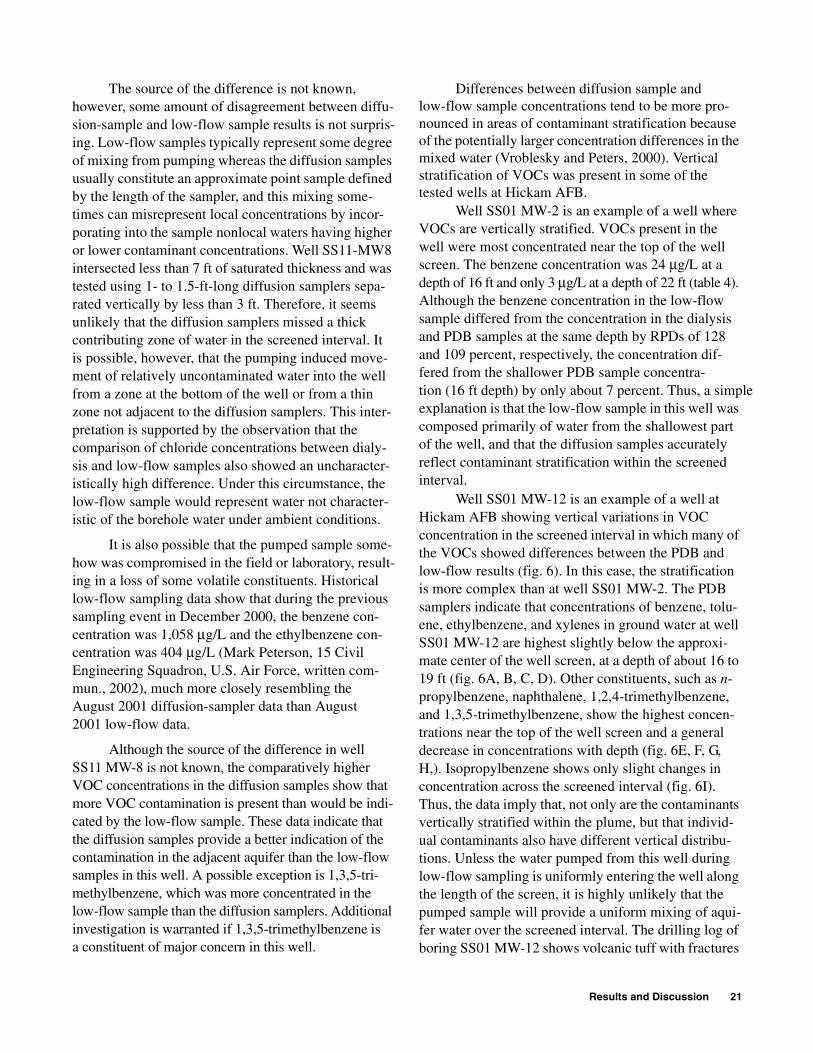
Results and Discussion 21
The source of the difference is not known, however, some amount of disagreement between diffu-sion-sample and low-flow sample results is not surpris-ing. Low-flow samples typically represent some degree of mixing from pumping whereas the diffusion samples usually constitute an approximate point sample defined by the length of the sampler, and this mixing some-times can misrepresent local concentrations by incor-porating into the sample nonlocal waters having higher or lower contaminant concentrations. Well SS11-MW8 intersected less than 7 ft of saturated thickness and was tested using 1- to 1.5-ft-long diffusion samplers sepa-rated vertically by less than 3 ft. Therefore, it seems unlikely that the diffusion samplers missed a thick contributing zone of water in the screened interval. It is possible, however, that the pumping induced move-ment of relatively uncontaminated water into the well from a zone at the bottom of the well or from a thin zone not adjacent to the diffusion samplers. This inter-pretation is supported by the observation that the comparison of chloride concentrations between dialy-sis and low-flow samples also showed an uncharacter-istically high difference. Under this circumstance, the low-flow sample would represent water not character-istic of the borehole water under ambient conditions.
It is also possible that the pumped sample some-how was compromised in the field or laboratory, result-ing in a loss of some volatile constituents. Historical low-flow sampling data show that during the previous sampling event in December 2000, the benzene con-centration was 1,058 µg/L and the ethylbenzene con-centration was 404 µg/L (Mark Peterson, 15 Civil Engineering Squadron, U.S. Air Force, written com-mun., 2002), much more closely resembling the August 2001 diffusion-sampler data than August 2001 low-flow data.
Although the source of the difference in well SS11 MW-8 is not known, the comparatively higher VOC concentrations in the diffusion samples show that more VOC contamination is present than would be indi-cated by the low-flow sample. These data indicate that the diffusion samples provide a better indication of the contamination in the adjacent aquifer than the low-flow samples in this well. A possible exception is 1,3,5-tri-methylbenzene, which was more concentrated in the low-flow sample than the diffusion samplers. Additional investigation is warranted if 1,3,5-trimethylbenzene is a constituent of major concern in this well.
Differences between diffusion sample and low-flow sample concentrations tend to be more pro-nounced in areas of contaminant stratification because of the potentially larger concentration differences in the mixed water (Vroblesky and Peters, 2000). Vertical stratification of VOCs was present in some of the tested wells at Hickam AFB.
Well SS01 MW-2 is an example of a well where VOCs are vertically stratified. VOCs present in the well were most concentrated near the top of the well screen. The benzene concentration was 24 µg/L at a depth of 16 ft and only 3 µg/L at a depth of 22 ft (table 4). Although the benzene concentration in the low-flow sample differed from the concentration in the dialysis and PDB samples at the same depth by RPDs of 128 and 109 percent, respectively, the concentration dif-fered from the shallower PDB sample concentra-tion (16 ft depth) by only about 7 percent. Thus, a simple explanation is that the low-flow sample in this well was composed primarily of water from the shallowest part of the well, and that the diffusion samples accurately reflect contaminant stratification within the screened interval.
Well SS01 MW-12 is an example of a well at Hickam AFB showing vertical variations in VOC concentration in the screened interval in which many of the VOCs showed differences between the PDB and low-flow results (fig. 6). In this case, the stratification is more complex than at well SS01 MW-2. The PDB samplers indicate that concentrations of benzene, tolu-ene, ethylbenzene, and xylenes in ground water at well SS01 MW-12 are highest slightly below the approxi-mate center of the well screen, at a depth of about 16 to 19 ft (fig. 6A, B, C, D). Other constituents, such as n-propylbenzene, naphthalene, 1,2,4-trimethylbenzene, and 1,3,5-trimethylbenzene, show the highest concen-trations near the top of the well screen and a general decrease in concentrations with depth (fig. 6E, F, G, H,). Isopropylbenzene shows only slight changes in concentration across the screened interval (fig. 6I). Thus, the data imply that, not only are the contaminants vertically stratified within the plume, but that individ-ual contaminants also have different vertical distribu-tions. Unless the water pumped from this well during low-flow sampling is uniformly entering the well along the length of the screen, it is highly unlikely that the pumped sample will provide a uniform mixing of aqui-fer water over the screened interval. The drilling log of boring SS01 MW-12 shows volcanic tuff with fractures

22 Evaluation of Passive Diffusion Bag and Dialysis Samplers in Selected Wells at Hickam Air Force Base, Hawaii, July 2001
at depths of 14, 18, and 19 ft and a porous, wet weath-ered tuff between 19.05 and 22.5 ft below land surface (Mark Peterson, 15 Civil Engineering Squadron, U.S. Air Force, written commun., 2002). It is probable that water enters the well nonuniformly with primary
movement through the wet weathered tuff near the bottom of the screen or through fractures. Thus, it is not surprising that several of the VOC concentrationsshow disagreement between the PDB and low-flow method in this well.
Figure 6. Vertical distributions of volatile organic compounds in dialysis and low-flow samples from well SS01 MW-12, Hickam Air Force Base, Hawaii, July 2001.
A. Benzene B. Toluene
C. Ethylbenzene D. m,p-Xylene
E. n-Propylbenzene F. Naphthalene
G. 1,2,4-Trimethylbenzene
I. Isopropylbenzene
H. 1,3,5-Trimethylbenzene
CONCENTRATION, IN MICROGRAMS PER L ITER
DE
PT
H,
I
N
FE
ET
B
EL
OW
T
OP
O
F
CA
SI
NG
EXPLANATON
0 400 800 1200
12
14
16
18
20
22
24
Dialysis samplePassive diffusion bag sampleLow-flow sample
0 200 400 600 800
12
14
16
18
20
22
24
0 400 800 1200
12
14
16
18
20
22
240 200 400 600 800 1000
12
14
16
18
20
22
24
0 10 20 30 40 50 60 70 80
12
14
16
18
20
22
24
0 20 40 60 80 100 120 140 160
12
14
16
18
20
22
240 10 20 30 40 50 60 70
12
14
16
18
20
22
24
0 50 100 150 200 250 300
12
14
16
18
20
22
240 20 40 60 80 100
12
14
16
18
20
22
24

Results and Discussion 23
Another situation that can produce concentration differences between diffusion and low-flow methods is when the pumping draws VOCs toward the well from areas of higher concentration not directly adjacent to the screen, resulting in higher concentrations in the pumped sample than in the diffusion sample. It is reasonable to expect an area of complex vertical VOC stratification, such as at well SS01 MW-12, to also be characterized by complex lateral VOC distribution. Thus, it is likely that the pumped sample from well SS01 MW-12 represents, not only a complex integra-tion of vertical constituents, but also the lateral move-ment of concentrations toward the well that may differ from those in the aquifer directly adjacent to the well screen. In such a situation, the concentrations of specific VOCs in the pumped sample may deviate from concentrations in diffusion samples by varying
amounts in the same well. Thus, some VOCs, such as benzene and ethylbenzene, are more concentrated in the pumped sample than in the diffusion samples, whereas others, such as toluene and m,p-xylene, are more concentrated in the diffusion samples than in the pumped sample (fig. 6). The data from well SS01 MW-12 imply that the diffusion-sample results represent VOC concentrations under ambient conditions. The low-flow sample results represent VOC concentrations resulting from preferential flow and/or mixing in a complexly stratified system and possibly include concentrations representing conditions not in the direct vicinity of the well screen for some constituents.
In general, the two types of diffusion samplers appeared to produce concentrations that represented ambient conditions for most constituents in most wells. A general summary is shown in table 5.
Table 5. Summary of diffusion sampler ability to produce an accurate representation of the ambient water in tested wells at Hickam Air Force Base, Hawaii, July 2001
[VOCs, volatile organic compounds; PDB, passive diffusion bag; ---, data not available; µg/L, micrograms per liter]
Well
Does the diffusion sampler appear to produce an accurate representation of the ambient water?
Chloride (dialysis samplers)
Sulfate (dialysis
samplers)
Total iron (dialysis sample)
Dissolved iron
(dialysis sample)
VOCs(dialysis and low-flow samples)
SS01 MW-2 Possibly, but does not reflect pumped water.
Yes Yes --- Probably yes. The low-flow samples may represent water coming in near the top of the screen.
SS01 MW-6 Yes Yes Probably not Yes Yes
SS01 MW-8 Yes --- Yes Yes Proably yes; however, a comparatively poor match was obtained for n-propylbenzene. Further testing may be war-ranted if n-propylbenzene is a parameter of major concern in this well.
SS01 MW-11 Yes Yes --- --- Yes, however, isopropylbenzene was more concentrated in the low-flow than in the PDB sample (5.3 µg/L), so further testing in this well may be warranted if isopropylbenzene is a parame-ter of major concern.
SS01 MW-12 Insufficient data for statistical analysis, but it does not appear to reflect pumped water.
Yes --- --- Uncertain. The well exhibited complex stratification with a close match for some major VOCs and a poor match for others. It is unclear whether the low-flow sample or the diffusion sam-ple is producing the more representative sample.
SS11 MW-8 Possibly, but does not reflect pumped water.
Yes Yes Yes Yes; however differences were found for 1,3,5-trimethylben-zene. Additional investigation is warranted if 1,3,5-trimethyl-benzene is a constituent of major concern in this well.
SS13 MW-4 Yes Yes --- --- Yes
SS13 MW-10 Yes --- --- --- ---
SS13 MW-17 Yes Yes --- --- ---
SS15 MW-2 Yes Yes Yes Yes ---
SS15 MW-4 Yes --- Yes Yes Yes
SS15 MW-5 Yes Yes Probably not Probably not ---
SS15 GT-K5 Yes Yes --- --- Yes

24 Evaluation of Passive Diffusion Bag and Dialysis Samplers in Selected Wells at Hickam Air Force Base, Hawaii, July 2001
Advantages and Limitations of Diffusion Samplers at Hickam Air Force Base
There are several advantages of PDB samplers. They can be deployed and recovered simply and rap-idly. The low cost associated with water sampling using PDB samplers makes them a cheaper alternative at Hickam AFB than low-flow sampling (Earth Tech, Inc., 2001). The method requires minimum decontami-nation and produces little or no investigation-derived wastewater. The samplers appear to be durable for long-term deployment of at least 6 months (Church, 2000) with no loss of bag integrity in most contami-nated waters. PDB samplers are particularly practical in carbonate environments, such as Hawaii, where alkalinity can be high enough to cause effervescence when an acid preservative is added. The effervescence results in loss of VOCs by volatilization. Collection of VOCs without addition of acid preservative prevents volatilization loss, but significantly shortens the sam-ple holding time. Because PDB-sampler membranes transmitted VOCs but not alkalinity at this study site, the data imply that the PDB samplers collect VOCs in a nonalkaline matrix, allowing the addition of an acid preservative even when sampling from a highly alka-line aquifer. Additional work is ongoing to determine whether this applies to other sites.
There are also several advantages of dialysis samplers. The samplers are relatively inexpensive and are easy to deploy and recover. They have an advan-tage over PDB samplers in that the dialysis samplers are effective for both inorganic and organic solutes.
Diffusion samplers have the additional advantage over pumped samples in that the diffusion samplers potentially can measure contaminant stratification in the screened interval. The samplers also are not subject to interferences from turbidity because of the small membrane pore size (about 10 angstroms or less for PDB samplers and about 18 angstroms for dialysis samplers).
Both types of diffusion samplers also have lim-itations. The limitation of the PDB sampler is that it primarily should be used where VOCs are the main or only constituents being monitored, because inorganic and most semivolatile solutes do not rapidly pass through the membrane. The major limitation of the dialysis sampler is that regenerated cellulose is the only dialysis membrane commercially available in conve-nient-sized tubing for well applications at the time of this writing (2002). Although regenerated cellulose is
a comparatively rugged membrane, it is subject to bio-degradation under field conditions. Most, but not all, of the dialysis samplers showed discoloring of the origi-nally white membrane after 2 weeks of deployment during this investigation (fig. 7). Although the mem-branes remained structurally sound during the 2-week deployment, it is unreasonable to expect them to sur-vive long-term deployment (for example, 3 months). Therefore, when using regenerated cellulose dialysis samplers for quarterly sampling, they probably should be deployed no sooner than 2 weeks prior to recovery unless field tests demonstrate a longer lifespan in the target well. The sampler degradation suggests that microbial activity on the membrane may affect the detected concentrations of bioactive solutes in some environments; however, no obvious detrimental effect from membrane interaction with the detected solute concentrations within the dialysis samplers was observed at the sites tested during this investigation.
An additional potential limitation of diffusion samplers is that they reflect concentrations in the screened or open interval that move to the sampler under ambient flow conditions. This is a limitation in situations where the contamination lies above or below the screen or vertical gradients in the well obscure strati-fication. However, this also can be an advantage in some situations where there is interest in knowing the concentrations in the vicinity of the screened interval, and the pumped sample represents water not in the vicinity of the screen that was transported to the well as a result of pumping.
Figure 7. Discoloration of dialysis sampler membrane after 2 weeks of deployment in a well, Hickam Air Force Base, Hawaii, July 2001.

Summary and Conclusions 25
Finally, caution must be used when using diffu-sion samplers deployed in anaerobic waters to collect redox-sensitive inorganic constituents. Oxidation of iron and other solutes can precipitate solutes from solution within the samplers, sometimes producing erroneous results (Vroblesky and others, 2002).
This report presents data comparing ground-water concentrations of both VOCs and inorganic solutes obtained from side-by-side tests of an updated dialysis sampler and PDB samplers to concentrations obtained by low-flow sampling in wells. The tests were conducted during July 2001 in 13 wells at Hickam Air Force Base, Hawaii.
The PDB samplers were purchased commer-cially. Each dialysis sampler was constructed onsite and consisted of a perforated plastic pipe inside a sleeve of high-grade regenerated cellulose tubular dialysis membrane.
In general, relatively favorable comparisons were found between concentrations in dialysis samples and low-flow samples for the predominant inorganic solutes examined for this investigation. Vertical con-centration gradients of solutes were observed in dialy-sis sampler data from most of the wells.
Chloride concentrations in the dialysis samples closely matched concentrations in most of the low-flow samples. The dialysis-sample chloride concentrations were not statistically different from the low-flow chlo-ride concentrations in 8 of the 13 tested wells. In 2 of the remaining 5 wells (wells SS13 MW-10 and SS15 MW-4) insufficient data were available to run a t-test. However, the low RPDs (6 and 3 percent, respectively) between concentrations from the low-flow sample and dialysis sample deployed at the same depth indicated a close match.
In most of the wells, the dialysis sampler data showed that chloride had a vertical concentration gra-dient or stratification. In these wells, it is likely that mixing during low-flow pumping produces some degree of concentration deviation from the adjacent dialysis sampler.
The chloride concentrations in two wells (SS01 MW-2, and SS11 MW-8) showed a statistical difference between the dialysis and low-flow samples. In these wells, and in a well in which the chloride concentrations
were not statistically analyzed (well SS01 MW-12), the chloride concentrations in the low-flow samples were higher than in the dialysis samples. The close match in chloride concentrations between sampling methods in other wells suggests that the differences in these wells may be attributed to well-specific factors rather than a diffusion-sampler deficiency. For example, it is possible that the low-flow pumping induced movement of water into the well that did not flow to the well under nonpumping conditions.
Sulfate concentrations showed a generally close match between results from dialysis samples and low-flow samples. Examination of vertical sulfate distribu-tions show that the concentration differences between the low-flow sample and the adjacent dialysis sample in most wells probably are due to the low-flow samples representing a mixing of concentrations in a stratified system, whereas the dialysis samples represent local-ized concentrations.
Iron concentrations also showed generally close agreement in most dialysis and low-flow samples. The data imply that iron concentrations in the dialysis samplers are representative of undisturbed well water, and the unfiltered pumped samples represent water and amounts of suspended sediment not normally moving through the well at the tested horizon.
Alkalinity measurements in dialysis samples closely matched the low-flow sample result or over-estimated it. An overestimation typically is not consid-ered a mismatch because it is not unusual for low-flow sampling to dilute concentrations by mixing. Thus, the alkalinity concentrations measured in the dialysis sam-pler probably approximate alkalinity concentrations in the undisturbed water column in the well. It is impor-tant to note, however, that the PDB samplers contained no detectable alkalinity at Hickam AFB, even when deployed in waters containing greater than 300 mg/L of alkalinity. The fact that the LDPE membrane of PDB samplers differentiates against alkalinity and have been shown to effectively transmit VOC concentrations implies that VOC samples can be collected from alka-line waters in a nonalkaline matrix without concern for volatilization loss by effervescence upon addition of acid preservative.
Only limited arsenic data were collected, however, the close match between arsenic concentra-tions in dialysis samples and both the unfiltered and filtered low-flow samples in well SS15 MW-4 implies that the dialysis samplers are capable of accurately collecting arsenic samples. Similarly, although only
SUMMARY AND CONCLUSIONS

26 Evaluation of Passive Diffusion Bag and Dialysis Samplers in Selected Wells at Hickam Air Force Base, Hawaii, July 2001
limited data are available for methane comparisons, the methane concentrations showed a relatively close match between dialysis and low-flow samples, imply-ing that the dialysis samples adequately represented ground-water methane concentrations. Lead, zinc, mercury, and copper concentrations were too low for an adequate evaluation of the dialysis sampler’s ability to accurately sample these constituents. Although sulfide concentrations in the dialysis samples varied from concentrations in low-flow samples by a broad range, the sulfide concentrations in the dialysis samples were all equal to or greater than the concentrations in the low-flow samples.
In general, the comparisons of VOC concentra-tions between the two different types of diffusion samples showed a relatively close correspondence. At concentrations less than 6 µg/L, the average concentration difference between dialysis and PDB samples for individual VOCs was 0.8 µg/L. At concentrations greater than 6 µg/L, the average RPD for individual VOCs was 16.7 percent between dialy-sis and PDB samplers from corresponding depths. The relatively close match in concentrations from the two different types of diffusion membranes indicates that the concentrations accurately represent concentra-tions of the tested constituents in water contacting the samplers.
Evaluation of diffusion samplers for VOCs was not appropriate in some of the tested wells because the wells contained no detectable VOCs without laboratory qualifiers (wells SS13 MW-10, SS13 MW-17, and SS15 MW-2). In other wells (SS13 MW-4 and SS15 GT-K5) containing only low concentrations of VOCs, the data imply that the diffusion samplers produced representative VOC concentrations. Data from well SS01 MW-11 also showed relatively low concentra-tions (less than 10 µg/L). The relatively close agree-ment between diffusion sampling and low-flow sampling in well SS01 MW-11 probably indicates that the diffusion samples provide representative VOC concentrations in that well; however, the slightly larger difference in isopropylbenzene concentrations suggest that further testing may be warranted if that constituent is of major interest. Samples from well SS01 MW-8 contained several VOCs at quantifiable concentrations less than 10 µg/L. Concentrations of most of these constituents from low-flow sampling agreed with concentrations from adjacent or nearby (3 ft) diffusion samplers, suggesting that the two methodologies were comparable at well SS01 MW-8. However, n-propyl-
benzene in well SS01 MW-8 was more concentrated by about 7.7 to 13 µg/L than in nearby diffusion samplers. If n-propylbenzene is a constituent of major concern in this well, then additional testing is warranted.
Substantial concentration differences between sampling methods were observed at some wells. Ben-zene, ethylbenzene, and xylene concentrations from well SS11 MW-8 were substantially lower in water from low-flow samples than in water from diffusion samplers. The data imply that the diffusion samples provide a better indication of the contamination in the adjacent aquifer than the low-flow samples in this well. A possible exception is 1,3,5-trimethylbenzene, which was more concentrated in the low-flow sample than in the diffusion samplers. Additional investigation is war-ranted if 1,3,5-trimethylbenzene is a constituent of major concern in this well.
Well SS01 MW-2 is an example of a well at Hickam AFB where VOCs are vertically stratified. VOCs present in the well were most concentrated near the top of the well screen. The data imply that the low-flow sample in this well was composed primarily of water from the shallowest part of the well and that the diffusion samples accurately reflect contaminant strati-fication within the screened interval.
Well SS01 MW-12 is an example of a well at Hickam AFB showing vertical variations in VOC concentration in the screened interval in which many of the VOCs showed differences between the PDB and low-flow results. In this case, the stratification is more complex than at well SS01 MW-2. Different VOCs are concentrated at different depths. The data from well SS01 MW-12 imply that the diffusion-sample results represent VOC concentrations under ambient condi-tions, and that the low-flow sample results represent VOC concentrations resulting from preferential flow and/or mixing in a complexly stratified system and possibly include concentrations representing condi-tions not in the direct vicinity of the well screen for some constituents.
Both dialysis and PDB samplers are relatively inexpensive and can be deployed rapidly and easily. PDB samplers are intended for sampling VOCs only, but dialysis samplers can sample both VOCs and inor-ganic solutes. Regenerated cellulose dialysis samplers, however, are subject to biodegradation and probably should be deployed no sooner than 2 weeks prior to recovery.
References 27
Barcelona, M., Wehrmann, H.A., and Varljen,. M.D., 1994, Reproducible well-purging procedures and VOC stabili-zation criteria for ground-water sampling: Ground Water, v. 32, p. 12-22.
Bertolin, A., Rudello, D., and Ugo, P., 1995, A new device for in-situ pore-water sampling: Marine Chemistry, v. 49, p. 233-239.
Bottomly, E.Z., and Bayley, I.L, 1984, A sediment porewater sampler used in root zones studies of the submerged macrophyte, Myriophyllum spicatum: Limnology and Oceanography, v. 29, p. 671-673.
Carignan, R., 1984, Interstitial water sampling by dialysis, methodological notes: Limnology and Oceanography, v. 29, p. 667-670.
Carignan, R., Rapin, F., and Tessier, A., 1985, Sediment porewater sampling for metal analysis--A comparison of techniques: Geochimica Cosmochimica Acta, v. 49, p. 2493-2497.
Church, P.E., 2000, Evaluation of a diffusion sampling method for determining concentrations of volatile organic compounds in ground water, Hanscom Air Force Base, Bedford, Massachusetts: U.S. Geological Survey Water-Resources Investigations Report 00-4242, 20 p.
Davis, A., and Atkins, D., 2001, Metal distribution in Clark Fork River sediments: Environmental Science and Tech-nology, v. 35, p. 3501-3506.
Davis, A., and Galloway, J.N., 1993, Distribution of Pb between sediments and pore water in Woods Lake, Adirondack State Park, New York, U.S.A.: Applied Geochemisty, v. 8, p. 51-65.
Diog, Lorne, and Liber, Karsten, 2000, Dialysis minipeeper for measuring pore-water metal concentrations in labo-ratory sediment toxicity and bioavailability tests: Envi-ronmental Toxicology and Chemistry, v. 19, no. 12, p. 2882-2889.
Earth Tech, Inc., 2001, United States Air Force PDB sampler demonstration study, Hickam AFB, Hawaii: Consult-ant’s report prepared for Air Force Center for Environ-mental Excellence, Brooks, AFB, Texas, 43 p.
Gaillard J.F., Jeandel, C., Michard, G., Nicolas, E., and Renard, D., 1986, Interstitial Water Chemistry of Villefranche Bay Sediments: Trace Metals Diagenesis: Marine Chemistry, v. 18, p. 233-247.
Hare, L., Carignan, R., and Huerta-Diaz, M., 1994, A field experimental test of the hypothesis that acid volatile sulfide (AVS) concentrations improve the prediction of metal toxicity and accumulation by benthic invertebrates: Limnology and Oceanography, v. 39, p. 1653-1668.
Hare, P.W., 2000, Passive diffusion bag samplers for moni-toring chlorinated solvents in ground water: The Second
International Conference on Remediation of Chlorinated and Recalcitrant Compounds, Battelle, May 22-25, 2000, Monterey, California, v. 2, no. 1, p. 377-386.
Hesslein, R.H., 1976, An in situ sampler for close interval pore water studies: Limnology and Oceanography, v. 21, p. 912-914.
Kaplan, Edward, Banerjee, Sujit, Ronen, Daniel, Magaritz, Mordeckai, Machlin, Albert, Sosnow, Michael, and Koglin, Eric, 1991, Multilayer sampling in the water-table region of a sandy aquifer: Ground Water, v. 29, no. 2, p. 191-198.
Lyford, F.P, Flight, L.E., Stone, J.R., and Clifford, Scott, 1999a, Distribution of trichloroethylene and geologic controls on contaminant pathways near the Royal River, McKin Superfund site area, Gray, Maine: U.S. Geologi-cal Survey Water-Resources Investigations Report 99-4125, 20 p.
Lyford, F.P., Kliever, J.D., and Clifford, Scott, 1999b, Vola-tile organic compounds detected in vapor-diffusion sam-plers placed in sediments along and near the shoreline at Allen Harbor Landfill and Calf Pasture Point, Davis-ville, Rhode Island, March-April 1998: U.S. Geological Survey Open-File Report 99-74, 9 p.
Magaritz, M., Wells, A.J., Amiel, A.J., and Ronen, D., 1989, Application of a multiplayer sampler based on the dialy-sis cell technique for the study of trace metals in ground water: Applied Geochemistry, v. 4, p. 617-624.
Mayer, L.M., 1976, Chemical water sampling in lakes and sediments with dialysis bags: Limnology and Oceanog-raphy, v. 21, p. 909-912.
McClellan AFB Environmental Management Directorate, 2000, Technology application analysis report for passive diffusion membrane samplers: Sacramento, Calif., McClellan Air Force Base Environmental Management, 282 p.
Paludan, C., and Morris, J.T., 1999, Distribution and speciation of phosphorus along the salinity gradient in intertidal marsh sediments: Biogeochemistry, v. 45, p. 197-221.
Parsons Engineering Science, Inc., 1999, Technical report for the evaluation of ground water diffusion samplers: Consultant’s report prepared for Air Force Center for Environmental Excellence Technology Division, December 1999, 35 p.
Ronen, Daniel, Magaritz, Mordeckai, and Levy, Itzhak, 1986, A multi-layer sampler for the study of detailed hydrochemical profiles in ground water: Water Research, v. 20, no. 3, p. 311-315.
Savoie, J.G., LeBlanc, D.R., Blackwood, D.S., McCobb, T.D., Rendigs, R.R., and Clifford, Scott, 2000, Delinea-tion of discharge areas of two contaminant plumes by use of diffusion samplers, Johns Pond, Cape Cod, Mas-sachusettes, 1998: Geological Survey Water-Resources Investigations Report 00-4017, 30 p.
REFERENCES

28 Evaluation of Passive Diffusion Bag and Dialysis Samplers in Selected Wells at Hickam Air Force Base, Hawaii, July 2001
Savoie, J.G., Lyford, F.P., and Clifford, Scott, 1999, Potential for advection of volatile organic compounds in ground water to the Cochato River, Baird & McGuire Super-fund Site, Holbrook, Massachusettes, March and April 1998: U.S. Geological Survey Water-Resources Investi-gations Report 98-4257, 19 p.
Shanklin, D.E., Sidle, W.C., and Ferguson, M.E., 1995, Micro-purge low-flow sampling of uranium-contami-nated ground water at the Fernald Environmental Management Project: Ground Water Monitoring and Remediation, v. 15, no. 3, p. 168-176.
Tessier, A., Carignan, R., Dubreuil, B., and Rapin, F., 1989, Partitioning of zinc between the water column and the oxic sediments in lakes: Geochimica Cosmochimica Acta, v. 53, p. 1511-1522.
U.S. Environmental Protection Agency, 1983, Methods for chemical analysis of water and wastes: Cincinnati, Ohio, U.S. Environmental Monitoring Support Labora-tory, EPA 600/4-79-020.
_____ 1992, Test methods of evaluating solid waste, physi-cal/chemical methods, SW-846 (3d ed.): Cincinnati, Ohio, Environmental Monitoring and Support Labora-tory, Office for Research and Development, 910 p.
_____ 1999, On-line SW-846 methods: accessed December 21, 1999, at URL http://search.epa.gov/epaoswer/hazwaste/test/tx8xxx.htm#8XXX.
Vroblesky, D.A., 2000, Influence of stream orientation on contaminated ground-water discharge, in Proceedings of the ground-water/surface-water interactions workshop, January 26-28, 1999, U.S. Environmental Protection Agency EPA/542/R-00-007, Denver, Colorado: p. 143-147.
______ 2001, User’s guide for polyethylene-based passive diffusion bag samplers to obtain volatile organic com-pound concentrations in wells, Part 1: Assembly and quality control and assurance: U.S. Geological Survey Water-Resources Investigations Report 01-4060, 18 p.
Vroblesky, D.A., Borchers, J.W., Campbell, T.R., and Kin-sey, Willey, 2000, Investigation of polyethylene passive diffusion samplers for sampling volatile organic com-pounds in ground water at Davis Global Communica-tion, Sacramento, California, August 1998 to February 1999: U.S. Geological Survey Open-File Report 00-307, 13 p.
Vroblesky, D.A., and Hyde, W.T., 1997, Diffusion samplers as an inexpensive approach to monitoring VOCs in ground water: Ground Water Monitoring and Remedia-tion, v. 17, no. 3, p. 177-184.
Vroblesky, D.A., Lorah, M.M., and Trimble, S.P., 1991, Mapping zones of contaminated ground-water discharge using creek-bottom-sediment vapors, Aberdeen Proving Ground, Maine: Ground Water, v. 29, no. 1, p. 7-12.
Vroblesky, D.A., Nietch, C.T., Robertson, J.F., Bradley, P.M., Coates, John, and Morris, J.T., 1999, Natural attenuation potential of chlorinated volatile organic compounds in ground water, TNX flood plain, Savan-nah River site, South Carolina: U.S. Geological Survey Water-Resources Investigations Report 99-4071, 43 p.
Vroblesky, D.A., and Peters, B.C., 2000, Diffusion sampler testing at Naval Air Station North Island, San Diego County, California, November 1999 to January 2000: U.S. Geological Survey Water-Resources Investiga-tions Report 00-4182, 34 p.
Vroblesky, D.A., and Petkewich, M.D., 2000, Field testing of passive diffusion bag samplers for volatile organic com-pound concentrations in ground water, Naval Industrial Reserve Ordnance Plant, Fridley, Minnesota, November 1999 and May 2000: U.S. Geological Survey Water-Resources Investigations Report 00-4246, 10 p.
Vroblesky, D.A., Petkewich, M.D., and Campbell, T.R., 2002, Field tests of diffusion samplers for inorganic constituents in wells and at a ground-water-discharge zone: U.S. Geological Survey Water-Resources Investi-gations Report 02-4031, 24 p.
Vroblesky, D.A., Rhodes, L.C., and Robertson, J.F., 1996, Locating VOC contamination in a fractured-rock aquifer at the ground-water/surface-water interface using pas-sive vapor collectors: Ground Water, v. 34, no. 2, p. 223-230.
Vroblesky, D.A., and Robertson, J.F., 1996, Temporal changes in VOC discharge to surface water from a frac-tured rock aquifer during well installation and operation, Greenville, S.C.: Ground Water Monitoring and Reme-diation, v. 16, no. 3, p. 196-201.
Webster, I.T., Teasdale, P.R., and Grigg, N.J., 1998, Theo-retical and experimental analysis of peeper equilibration dynamics: Environmental Science and Technology, v. 32, no. 11, p. 1727-1733.

USG
S WR
IR 02-4159
VrobleskyEvaluation of Passive D
iffusion Bag and D
ialysis Samplers in Selected W
ells at Hickam
Air Force B
ase, Haw
aii, July 2001