Embed Size (px)
Citation preview

Evaluation of Mobile Ad-Hoc Network of Unmanned Aerial Vehicles (UAVs)
A Degree's Thesis
Submitted to the Faculty of the
Escola Tècnica d'Enginyeria de Telecomunicació de Barcelona
Universitat Politècnica de Catalunya
by
Jordi Riera
In partial fulfilment
of the requirements for the degree in
Ciències i Tecnologies de Telecomunicació ENGINEERING
Advisor: Ilker Demirkol
Barcelona, June 2014

1
Abstract
Wireless Mesh Networks (WMNs) are an emerging technology that is still relatively unknown to the general public but it could be a key development in the future. Nowadays there is no immediate need to deploy this kind of network because the current ones perform well, but in wide areas they do not seem to work as well as expected.
WMNs could solve this problem while reducing infrastructure and maintenance costs since they are self-forming and potentially more intelligent. They seem to be the best approach to what is known as the Internet of Things, a global device interconnection.
This thesis explores their capabilities at a low scale, but adds the UAVs because they are mobile devices that might force the network to adapt. Also a mesh between UAVs could be used for communication and coordination between flying devices.
2
Resum
Les Xarxes en Malla Inalàbriques són una tecnologia emergent encara poc coneguda, però en un futur poden esdevenir molt importants. Actualment no hi ha cap necessitat inmediata per implementarles perquè les xarxes inalàmbriques actuals són suficients, però és en grans arees on fallen.
Aquestes xarxes poden resoldre aquest problema alhora reduint costos en infraestructura i manteniment ja que s’autoconnecten i potencialment són mes intel·ligents. Sembla ser que són la millor opció per la formació de la Internet de les coses, una xarxa global de tot tipus d’aparells.
Aquesta tesi investiga les seves capacitats a petita escala, però afegeix les naus autotripulades perquè al desplaçarse fan que la xarxa s’hagi d’adaptar. A més a més una xarxa entre naus autotripulades pot ser util per la communicació i coordinació entre elles.
3
Resumen
Las Redes en Malla Inalámbricas son una tecnología emergente que aún es desconocida pero que puede ser un desarrollo de gran importancia en el futuro. Actualmente no hay ninguna necesidad inmediata para implementarlas porqué las redes actuales funcionan bien, pero cuando se trata de usarlas para grandes áreas no funcionan tan bien.
Estas redes pueden solucionar este problema reduciendo los costos en infraestructura y mantenimiento ya que se forman ellas solas y son potencialmente más inteligentes. Parece ser que son la mejor opción para el Internet de las cosas, una red global entre dispositivos.
Esta tesis investiga sus capacidades a pequeña escala, pero añade las naves no tripuladas ya que representan nodos móviles que fuerzan la red a adaptarse. Además una malla entre naves no tripuladas puede usarse para comunicación y coordinación entre ellas.
4
Acknowledgements
I want to appreciate the effort the supervisor has made of providing some guideline during this project as well as the research group that provided the IRIS quadcopter when it was needed.
Also I appreciate the numerous people that provide help and explanations to numerous Internet blogs, it solved and aided some of the software related problems.

5
Revision history and approval record
Revision Date Purpose
0 3/7/2014 Document creation
1 9/07/2014 Document revision
2 10/07/2014 Document revision
3 11/07/2014 Document revision
DOCUMENT DISTRIBUTION LIST
Name e-mail
Jordi Riera [email protected]
Ilker Demirkol [email protected]
Written by: Reviewed and approved by:
Date 03/07/2014 Date 11/07/2014
Name Jordi Riera Name Ilker Demirkol
Position Project Author Position Project Supervisor

6
Table of contents
Abstract ............................................................................................................................ 1
Resum .............................................................................................................................. 2
Resumen .......................................................................................................................... 3
Acknowledgements .......................................................................................................... 4
Revision history and approval record ................................................................................ 5
Table of contents .............................................................................................................. 6
List of Figures ................................................................................................................... 8
List of Tables .................................................................................................................. 10
1. Introduction .............................................................................................................. 11
1.1. Background ...................................................................................................... 11
1.2. Wireless Mesh Networks .................................................................................. 11
1.3. IEEE 802.11s & Open80211s ........................................................................... 13
1.4. Objectives......................................................................................................... 17
1.5. Requirements and Specifications ..................................................................... 19
1.6. Work Plan ......................................................................................................... 19
1.7. Gantt Diagram .................................................................................................. 21
1.8. Incidences and Deviations ................................................................................ 22
2. State of the art of the technology used or applied in this thesis: ............................... 23
2.1. Cozybit ............................................................................................................. 23
2.2. Initial Evaluation of an IEEE 802.11s-based MANET ........................................ 23
2.3. Navigation for Robots with Wi-Fi and CV .......................................................... 23
3. Methodology / project development: ........................................................................ 24
3.1. Operating System ............................................................................................. 24
3.2. Wireless Adapters ............................................................................................ 24
3.3. Raspberry Pi ..................................................................................................... 25
3.4. AR Drone ......................................................................................................... 25
3.5. IRIS Quadcopter ............................................................................................... 26
3.6. Wireless Configuration Tools ............................................................................ 27
3.7. Testing Tools .................................................................................................... 28

7
4. Results .................................................................................................................... 30
4.1. Rasperry Pi tests .............................................................................................. 30
4.2. UAV tests ......................................................................................................... 38
5. Budget ..................................................................................................................... 43
6. Environment ............................................................................................................ 44
7. Conclusions and future development: ...................................................................... 45
Bibliography: ................................................................................................................... 46
Appendices: .................................................................................................................... 47
A. Usage of ifconfig/iw .......................................................................................... 47
B. Raspberry Pi kernel cross compilation .............................................................. 52
C. Connection from laptop to Raspberry Pi ........................................................... 54
D. AR Drone ......................................................................................................... 58
Glossary ......................................................................................................................... 63

8
List of Figures
1.2 Common Wireless Networks in a star topology, each station needs a router and some users do not have connectivity because they are in an open field. ........................ 12
1.2 Wireless Mesh Network in a mesh topology, it can cover more area and the stations are interconnected making peer to peer much simpler. ..................................... 12
1.3 Path request operation in HWMP ...................................................................... 14
1.3 Path reply and path error operation in HWMP ................................................... 14
1.3 Airtime Link Formula ......................................................................................... 15
1.3 Sleeping station safety margin behaviour .......................................................... 16
1.3 Data transmission management between active and light sleep station ............ 16
1.3 Example scenario with customized power save modes. .................................... 17
1.7 Gantt diagram first half ...................................................................................... 21
1.7 Gantt diagram second half ................................................................................ 21
3.2 Penguin Wireless USB Adapter ........................................................................ 24
3.2 Wi-Pi USB Adapter ........................................................................................... 25
3.3 Raspberry Pi Model B ....................................................................................... 25
3.4 AR Drone .......................................................................................................... 26
3.4 Battery for Raspberry Pi .................................................................................... 26
3.5 IRIS and Raspberry assembly ........................................................................... 27
3.7 JPerf user interface ........................................................................................... 29
4.1 Two nodes mesh schematic .............................................................................. 30
4.1 Three nodes mesh schematic ........................................................................... 31
4.1 Four nodes mesh schematic ............................................................................. 32
4,1 TCP Throughput graph ..................................................................................... 34
4.1 UDP Throughput graph ..................................................................................... 34
4.1 UDP Losses graph ............................................................................................ 35
4.2 UAV mesh scenario .......................................................................................... 39
4.2 UAV distance mesh scenario ............................................................................ 40

9
4.2 UAV TCP Throughput graph ............................................................................. 40
4.2 UAV UDP Throughput graph ............................................................................. 41
4.2 UAV peering link mesh scenario ....................................................................... 42
6 Iris Li-Po battery pack ....................................................................................... 44
C Windows’ IP configuration ................................................................................. 54
C Windows’ PuTTY .............................................................................................. 55
D USB pinout ........................................................................................................ 58
D Detail of the connector ...................................................................................... 58
D The whole cable ................................................................................................ 59

10
List of Tables
1.3 Airtime Link Metric Parameters ......................................................................... 15
4.1 Two nodes TCP. ............................................................................................... 31
4.1 Two nodes UDP ................................................................................................ 31
4.1 Three nodes TCP .............................................................................................. 32
4.1 Three nodes UDP ............................................................................................. 32
4.1 Four nodes TCP. ............................................................................................... 33
4.1 Four nodes UDP ............................................................................................... 33
4.1 Power Save Mode TCP ..................................................................................... 35
4.1 Power Save Mode UDP .................................................................................... 36
4.1 Awake Window TCP. ........................................................................................ 36
4.1 Awake Window UDP ......................................................................................... 36
4.1 Beacon Interval TCP ......................................................................................... 37
4.1 Beacon Interval UDP ........................................................................................ 38
4.2 UAV three nodes TCP. ...................................................................................... 39
4.2 UAV three nodes UDP ...................................................................................... 39
4.2 Beacon Interval TCP ......................................................................................... 37
4.2 Beacon Interval UDP ........................................................................................ 38
5 Budget item list ................................................................................................. 43
5 Total hour costs ................................................................................................ 43

11
1. Introduction
1.1. Background
To get introduced to the overall subject and concepts of this thesis as well as the main objectives it is necessary to acquire a qualitative knowledge, background and limitations of nowadays wireless networks to understand the reasons behind this project.
Looking back in recent years, wireless networks have been experiencing a notable growth, partially thanks to the development of mobile communications, as a consequence now they are present virtually in every home and company as computer networks. Along with them, establishments or buildings more focused to leisure activities such as hotels, restaurants, cafés or even cruises and planes offer a new type of service using wireless networks that grant users Internet access. Moreover some cities are trying to implement some Wi-Fi areas to offer this service to their citizens.
Society has changed; Internet access has practically become a necessity, in such extent that nowadays people take Internet connectivity for granted nearly everywhere. However traditional wireless networks, although cheap and easy to deploy, have some limitations that for now are insignificant but if they are installed at large scales it is possible that they will become impractical or inefficient for some applications or configurations.
1.2. Wireless Mesh Networks
Wireless networks are typically composed by one or more access points (APs) connected to the Internet via Ethernet cable and devices near APs can connect with them wirelessly. But for example if a wireless network covering a college campus, malls or even an entire city has to be implemented some major drawbacks appear:
• It is not possible to extend the network beyond the wired backhaul deployment. • They become inefficient with peer to peer applications. • It becomes a fixed topology, this prevents the network from choosing a better path.
Consequently the cost and complexity of this installation might increase greatly due to having to install more Ethernet connections and repeaters. At the end the total throughput of the network might be reduced because repeaters are congesting the network as a result of not being able to reroute the traffic to a different node.
This is where wireless mesh networks are proven to be more resourceful, they offer the same benefits of common wireless networks but with additional features. The main difference between them is their topology; common wireless networks follow a star topology, where multiple devices are connected to a single source (AP) as shown in Figure 1, whereas wireless mesh networks obviously follow a mesh topology, where each node can act as an AP but at the same time it is connected with other APs wirelessly hence covering an area where more devices can be connected like in Figure 2. This topology can provide peer-to-peer connectivity between devices in the network itself and to the Internet if one or more nodes are connected to it through another type of network, Ethernet for example.

12
Wireless mesh networks solve the previous problem of covering a wide area, since they are much easier to deploy because they are self-forming, as long as they are in range of other APs. Hence they are easily reconfigurable, flexible and intelligent since their nodes are able to reroute the traffic through another path if it exists to avoid traffic congestion. Besides it makes the peer to peer communication much simpler.
However the way the network discovers new nodes, determines the best path to another node including the wired network, security issues, etc. has to be managed by a mesh protocol which increases in complexity.
Figure 1: Common Wireless Networks in a star topology , each stati on needs a router and some users do not have connectivity because they are in an ope n field.
Figure 2: Wireless Mesh Network in a mesh topology , it can cover more area and the stations are interconnected making peer to peer much simpler.
13
1.3. IEEE 802.11s & Open80211s
Considering the multiple implementations and solutions that this protocol can have, it was possible that each vendor would make each own protocol making virtually impossible the interoperability between different vendors. This is the reason a standard was needed, therefore an IEEE 802.11 group created the 802.11s standard, which provides a framework for the mesh networks. It defines a clear terminology and functionality but at the same time it leaves some room for custom implementations that may outperform the default ones.
Despite an existing standard, some testing and studies are still required to evaluate the overall performance of the protocol. In this case a Linux implementation of 802.11s called Open80211s will be used, this software is an open-source implementation of the ratified IEEE 802.11s. It is constantly under revision by its users since they can submit issues they found as well as new code to solve them, hence it is not guaranteed that this implementation will be error free in its totality although for the most common mesh functions it is supposed that it will work as expected.
First of all the most relevant architecture terminology will be defined to avoid confusion and to not mix concepts.
• Mesh Station: A standard node or station that implements all the mesh functionalities
• Access Point: Any station that provides access to the network services via the wireless medium.
• Mesh Gate: Any mesh station that connects a mesh network with a non-mesh 802.11 network
• Mesh Portal: A mesh node connected to a mesh network and to a to another type of network, typically the Internet
Notice that a single node can be labelled with multiple terms because if it conducts multiple functions. For example a mesh station can be at the same time an access point if it allows devices not belonging to the mesh to access its services. A mesh station can also be a mesh portal if it is also connected to the Internet via Ethernet cable [1].
Path Selection
One of the most important algorithms of the mesh has to be the path discovery and selection protocol. Mesh stations by default have to implement HWMP (Hybrid Wireless Mesh Protocol) but different vendors can use other methods, this is why other protocols like OLSR (Optimized Link State Routing Protocol) or B.A.T.M.A.N. (Better Approach To Mobile Ad-hoc Networking) have appeared but in this thesis the default HWMP will be used.
HWMP can operate in two modes, the proactive one requires a mesh station, typically a mesh portal, to be configured as a root node forming a tree structure with all the other nodes. This way the root node controls all the path management by continuously propagating routing messages to create or maintain paths, these messages are called RANN (Root Announcement messages) and contain some fields like:

14
• Root MAC address, which uniquely identifies the root node.
• TTL (time to live) that decreases at every node preventing messages looping in the mesh.
• Hop Count that allows each node to know the distance to the root node.
It is very important to know that the mesh network works in the MAC and PHY layers, hence it identifies each node by its MAC address and not by IP addresses, this is why they are called paths whereas with IP addresses the same concept is called route. RANNs by themselves do not create the paths, it is when a mesh station receive these messages that then sends PREQ (Path Request) messages to the root node identifying themselves via the node that send them a RANN. Once the root node receives the PREQ it then sends a PREP (Path Reply) message to the PREQ originator. If it succeeds both nodes will have had formed a path to the other node. The objective of this method is that at the end all nodes will have a path table indicating to which station they have to send messages to reach the root node. Whereas the root node will have a table indicating the path to all the other nodes.
On the other hand the reactive mode only creates paths on demand but it works the same way. When a node needs to send a message to another node it sends PREQ to its neighbor nodes. The neighbor nodes in turn will retransmit the same PREQ to other nodes until they reach the destination as shown in Figure 3a. Ultimately the destination node will receive a PREQ, then it will answer with a PREP and it will be transmitted through the same set of nodes that the PREQ was sent until it reaches back to the station that requested the path like in Figure 3b. Consequently a path will be formed and each station of that path will know to which node they have to send messages to eventually reach the destination. If for some reason some nodes cannot find the destination station or do not have more neighbors, the protocol manages that by sending back PERR (Path Error) messages to let the initial node know that through that set of nodes it will not find a path as illustrated in Figure 3b [1] [2]
PREQ
PREQ
PREQ
Source Destination
PREQ
PERR
PREP
PREP
PREP
Source Destination Figure 3a: Path request operation in HWMP
Figure 3b: Path reply and path error operation in HW MP

15
Airtime Link Metric
When a mesh network is sufficiently interconnected a node requesting for a path will receive multiple PREP frames indicating that there is more than one way to reach the destination node, this is where the Airtime Link Metric comes in the picture. The Airtime Link Metric is a measure of how good a path and it is the result of the following formula in Figure 4 and its corresponding parameters in Table 1
�� = �� + � �1
1 − ��
As can be seen this metric does not depend explicitly on the number of hops, hence a faster link with more hops could be chosen as the best path. However when there are multiple hops this metric accumulates over the previous one hence at the end of the path the nodes have a value of the overall cost of that path. The metric to calculate the theoretical cost of a path by default is the one present but this feature can also support a custom implementation [1].
Power Save Modes
Another feature relevant for this thesis is an energy saving operation mode called Mesh Power Save Mode, or PSM for short. The default mode is the Active Mode which is the operation mode that does not try to save power and is always awake, and the station is able to receive or transmit frames at any time. Then there are two power saving modes that are called light sleep and deep sleep modes.
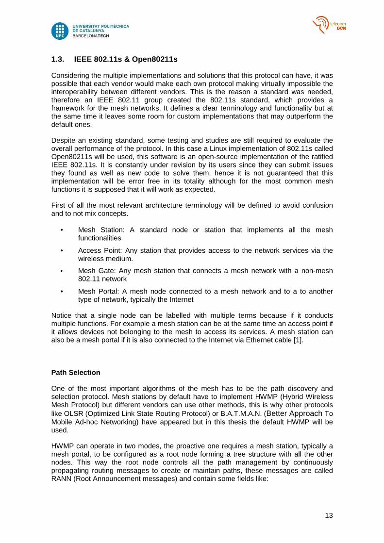
Before explaining them is necessary to understand how two stations communicate to see where power save modes take advantage of and what problems it has to solve. First of all stations send beacons at a fixed interval to their neighbors, and all the neighbors are aware of that timing and they can expect within an error margin when they will receive a beacon. The light sleep mode switches between the Awake and Doze states, if it is in Doze state it will awake to send its beacon but it will also awake to receive beacons when it expects them, and it will go to sleep afterwards. In case they miss a beacon stations increase the size of the window of time they are awaken to try to compensate for possible time drifts as represented in Figure 5.
Parameter Description
O Channel access overhead including frame headers, access protocol frames, etc. in time units
Bt Test frame length in bits
r Transmission data rate
ef Test frame error rate
Figure 4: Airtime Link Formula Table 1: Airtime Link Metric Parameters
16
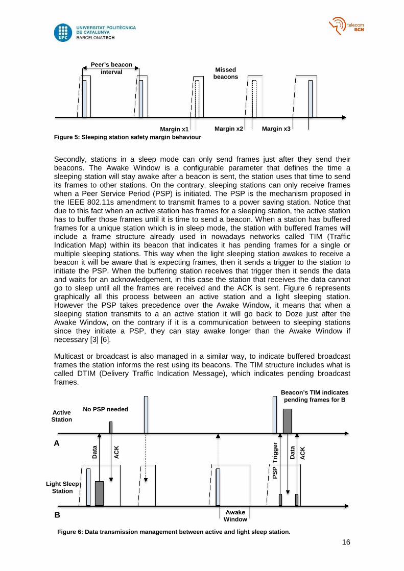
Secondly, stations in a sleep mode can only send frames just after they send their beacons. The Awake Window is a configurable parameter that defines the time a sleeping station will stay awake after a beacon is sent, the station uses that time to send its frames to other stations. On the contrary, sleeping stations can only receive frames when a Peer Service Period (PSP) is initiated. The PSP is the mechanism proposed in the IEEE 802.11s amendment to transmit frames to a power saving station. Notice that due to this fact when an active station has frames for a sleeping station, the active station has to buffer those frames until it is time to send a beacon. When a station has buffered frames for a unique station which is in sleep mode, the station with buffered frames will include a frame structure already used in nowadays networks called TIM (Traffic Indication Map) within its beacon that indicates it has pending frames for a single or multiple sleeping stations. This way when the light sleeping station awakes to receive a beacon it will be aware that is expecting frames, then it sends a trigger to the station to initiate the PSP. When the buffering station receives that trigger then it sends the data and waits for an acknowledgement, in this case the station that receives the data cannot go to sleep until all the frames are received and the ACK is sent. Figure 6 represents graphically all this process between an active station and a light sleeping station. However the PSP takes precedence over the Awake Window, it means that when a sleeping station transmits to a an active station it will go back to Doze just after the Awake Window, on the contrary if it is a communication between to sleeping stations since they initiate a PSP, they can stay awake longer than the Awake Window if necessary [3] [6].
Multicast or broadcast is also managed in a similar way, to indicate buffered broadcast frames the station informs the rest using its beacons. The TIM structure includes what is called DTIM (Delivery Traffic Indication Message), which indicates pending broadcast frames.
Peer’s beacon interval
Margin x1 Margin x2 Margin x3
Missed beacons
Figure 5: Sleeping station safety margin behaviour
Awake Window
Dat
a
AC
K
Dat
a
AC
K
PS
P T
rigge
r
Active Station
Light Sleep Station
Figure 6: Data transmission management between active and light sleep station.
Beacon’s TIM indicates pending frames for B
A
B
No PSP needed

17
This procedure is similar in light sleep and deep sleep mode, the main difference resides in that stations in deep sleep mode do not awake to receive beacons, they only switch to the Awake state when they have to send beacons and the following Awake Window. Hence other stations can only communicate during the Awake Window, however during that time they can trigger requests to make them awake during another time if necessary, to receive broadcast information for example.
This functionality implies that when a mesh station changes its sleeping state or becomes active it has to inform the other stations of that through management frames. However the power save mode is not absolute, meaning that a station can change its mode of operation towards a specific station. For example if there are two different paths to reach a destination but one of them is unreliable it is possible to configure the station as being active towards the good path and in deep sleep towards the unreliable path, adding flexibility to the network, an example is represented in Figure 7.
1.4. Objectives
This thesis revolves around building a wireless mesh network using the operating system Linux, then testing it using software tools. The use of UAVs grants the nodes with the ability to move around the scenario, this fact adds more complexity to the network compared to a network with static nodes.
Comparing to a static network, when nodes are moving we can expect that the throughput, delay and other parameters might be affected, consequently decreasing the overall quality of the network. Moreover we have to take into account that in that case it is more relevant how the network handles the path the traffic has to take when mobile nodes cannot be seen by their neighbor nodes or when they come into the range of another neighbors therefore creating new paths.
Additionally, since the network itself allows working in a low power consuming node, it is also interesting to verify that the network could still work consuming as less power as possible. Because mobile nodes, in this case UAVs, presumably will have a limited power source, it is essential that their network capabilities consume the minimum resources.
Although the main objective is to test a network with UAVs there are some minor goals that are necessary to be achieved, not only for this project but to establish a base and
Active
Light Sleep
Deep Sleep
Figure 7: Example scenario with customized power save modes.
Unreliable link
Reliable link

18
foundations on wireless mesh networks for future projects so they do not have to start from the ground. Some of these goals are:
• Analyze compatibilities: Determine the compatibilities and limitations of several potential hardware.
• Linux configuration: Establish the requirements and configurations for creating a wireless mesh network on Linux computers.
• Raspberry Pi configuration: Develop a simple configuration for Raspberry Pi devices.
• Network test: Decide which tests are used to verify the network and the way to do it.
Due to time and economic constraints, this thesis will have its limitations. It was not possible to test each driver that is supposed to support mesh networking, also the number of nodes constituting the network is limited by the number of laptops, Wi-Fi adapters and more importantly drones available at the moment.
1.5. Requirements and Specifications
To summarize, the requirements for this project to be successful are the following:
• Data transmission through the UAV nodes should be accomplished.
• Network Management with mobile UAV nodes.
• Performance evaluation of key network parameters
• Energy-efficient network operation through power save mode.
On the other hand, the specifications for this project are:
• Find a way to include mesh functionalities to a UAV.
• Establish the hardware and software requisites to configure mesh nodes in a simple way.
• Understanding the mesh protocol to find out which parameters are more relevant in different environments.

19
1.6. Work Plan
This project was divided in four separate work packages
Project: Evaluation of a Mesh Network with UAV WP ref: 1
Major constituent: Research Sheet 1 of 4
Short description: Research and learning of the 802.11s standard.
Start date: 18/2/14
End date: 3/3/14
Start event: Beginning
End event: Understanding of the working principles
Internal task T1: Information research, paper reading... Deliverables: Dates: -
Project: Evaluation of a Mesh Network with UAV WP ref: 2
Major constituent: Software Sheet 2 of 4
Short description: Creating a 802.11s mesh network with Linux using laptops.
Start date: 3/3/14
End date: 14/4/14
Start event: Understanding the requirements for mesh networking
End event: Defining the proper procedures to do mesh evaluation
Internal task T1: Configure Linux to be able to work with open802.11s implementation.
Internal task T2: Define testbeds
Internal task T3: Create a small mesh and do a simple evaluation.
Deliverables: Dates:

20
Project: Evaluation of a Mesh Network with UAV WP ref: 3
Major constituent: Hardware & Software Sheet 3 of 4
Short description: Use Raspberry Pi to create a mesh network and test compatibilities
Start date: 14/4/14
End date: 27/5/14
Start event: Obtaining Raspberry Pi devices
End event: Network evaluation
Internal task T1: Test the Raspberry Pi compatibilities
Internal task T2: Create a mesh network with them
Internal task T3: Evaluate the network with using the testbed
Deliverables:
Results obtained
Dates: 27/5/14
Milestones
Project: Evaluation of a Mesh Network with UAV WP ref: 4
Major constituent: Hardware & Software Sheet 4 of 4
Short description: Use UAVs to create a mesh network
Start date: 27/5/14
End date: 10/7/14
Start event: Obtaining of UAV
End event: Network evaluation
Internal task T1: Research about UAV operation
Internal task T2: Make the UAVs work as a node
Internal task T3: Evaluate the network with using the testbed
Deliverables:
Results obtained
Dates: 9/6/14
WP# Task# Short title Milestone / deliverable Date (week)
2 2 First mesh network implementation
First mesh network implementation
6
3 3 Raspberry Pi network testing
Reliable results from mesh implementation
15
3 3 Final results obtained with UAV evaluations
Set of results 21

21
1.7. Gantt Diagram
Figure 8a: Gantt diagram first half
Figure 8b: Gantt diagram second half

22
1.8. Incidences and Deviations
Until mid-April the project was developing as expected. The use of Raspberry Pi devices was not expected at the beginning, however the expected delay was affordable in the first place and also it offered a more insight view of mesh networking. Moreover the testing using Raspberry Pi had to be repeated in a closed environment where the devices were in short range and with less interference because they also operate at 2.4 GHz, the usual Wi-Fi frequency.
The reason for that is that the previous tests resulted in unreliable data which was not showing a logical behaviour and was difficult to get conclusions from. Also the testing using power save mode was limited because it usually made the mesh erratic, not being able to communicate with each other, having to reconfigure all the nodes again. In further inspection it was discovered that one of the Wi-Fi dongles attached to a Raspberry Pi was a bit loose and sooner or later its Raspberry Pi failed to recognize the device making resulting in mesh crashes because of some for unknown reasons at the time. But once knowing this issue was possible to test the power save mode with more nodes. Nevertheless it delayed a couple of weeks the initially planned date for the fourth work package.
More importantly, the major issue encountered was the AR Drone (UAV) malfunction. After some weeks trying to program it, dealing with several incompatibilities to add the mesh networking functionalities which would have solved the problem of adding weight to a flying device, which would probably destabilize it, it could also open the door to controlling some of the drone functionalities through the mesh. At the end of June suddenly the motors were not responding and no further test using could be done. It was discovered that the ADC was broken, consequently it could not read information from the motors. Because that drone is an old version, it did not have much support from the vendor meaning that spare pieces to repair it were not readily available and having to send it to repair it would take too much time. Also a financial decision was pending to make because it did not have warranty, the pieces are expensive and buying another one was taken into consideration also. Luckily another research group from the UPC provided us with another drone, however many days were lost which pushed the project to the dead line.

23
2. State of the art of the technology used or appli ed in this
thesis
2.1. Cozybit
Cozybit is an engineering firm situated in San Francisco, California, specialized in proximity networking–wireless interactions with nearby devices. They are the authors and main developers of the open80211s protocol. In their website they provide a simple tutorial for the basic configuration of mesh nodes and also other configurable features such as security using wpa supplicant or manual path selection. Other pages add specific information like how power save or synchronization works. Even if some information is missing or is a bit outdated, it is the most reliable source of information about the mesh networking implementation. It is also possible to post questions in their forum for possible issues.
2.2. “Initial Evaluation of an IEEE 802.11s-based Mobile Ad-Hoc Network for Collaborative Unmanned Aerial Vehicles ”, 2013 International Conference on Connected Vehicles and Expo (ICCVE), pp.145,150, 2-6 Dec. 2013
Researchers from the Virginia Commonwealth University, Ritchmond, VA, USA, investigated in the same subject matter, but at a different scale. For example instead of quadcopters, they worked with a couple of gliders connected to a ground station that were flying at an average altitude of 150 meters over an area approximately 500 meters across. They also did more hardware development because they had to fit a modem in the glider, in that case below the wings near the fuselage, and also chose an omnidirectional antenna because they also had to cope with significant differences in elevation between the nodes. Moreover they also had to do more software development since they were working with an embedded Linux distribution called OpenWrt. Additionally they had more time to check which channel was more robust for communication and at which transmit power, also they designed a more sophisticated testing method because for example they also keep track of the number of hops, frame retries and errors over time.
2.3. Navigation for Robots with Wi-Fi and CV [7]
Two students from the University of Aarhus, Denmark, developed a project with the AR Drone as their Master Thesis. The project consists on adding autonomy to the drone in regards to manoeuvring in a slightly dynamic environment. One of the requirements of the project was to add sensors to the drone and in this case they attached a USB Wi-Fi adapter. They documented the numerous steps to do that like assembling a custom USB cable for the drone, enabling the USB port, cross compiling code and install drivers. Most of these processes were very similar to what was required for the use of AR Drone USB interface in this thesis and the documentation has been a great aid.
24
3. Methodology / project development:
The following section will explain the main hardware components and also software used in this thesis that is found to be compatible with mesh networking.
3.1. Operating System
The Linux operating system includes a module called mac80211, it allows kernel to perform all necessary IEEE 802.11 frame management including the Open80211s capabilities. This module is included since the kernel version 2.6.26, however it is recommended to use the latest available kernel because some modifications have been made and more drivers are being supported. In this case the major part of experimentation has been made using Ubuntu 13.10, with the 3.12 kernel version and there was not major issues encountered.
Alternatively one can download and build another kernel named wireless-testing (http://wireless.kernel.org/en/developers/Documentation/git-guide), where the latest Linux wireless development is taken place. If it is not for development purposes the standard kernel should work well.
3.2. Wireless Adapters
To build the mesh network USB wireless adapters were used, it is very important to check that the driver which each adapter uses is compatible with mesh networking. You can check if the driver is compatible in this webpage: http://wireless.kernel.org/en/users/Drivers. A single driver can be used by multiple type of devices.
For this project we only tested two types of devices:
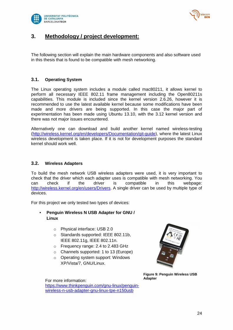
• Penguin Wireless N USB Adapter for GNU / Linux
o Physical interface: USB 2.0 o Standards supported: IEEE 802.11b,
IEEE 802.11g, IEEE 802.11n. o Frequency range: 2.4 to 2.483 GHz o Channels supported: 1 to 13 (Europe) o Operating system support: Windows
XP/Vista/7, GNU/Linux.
For more information: https://www.thinkpenguin.com/gnu-linux/penguin-wireless-n-usb-adapter-gnu-linux-tpe-n150usb
Figure 9: Penguin Wireless USB Adapter

25
• Wi-Pi – WLAN module for the Raspberry Pi
o Physical interface: USB 2.0 o Standards supported: IEEE
802.11b, IEEE 802.11g, IEEE 802.11n.
o Frequency range: 2.4 to 2.483 GHz
o Channels supported: 1 to 13 (Europe)
o Operating system support: Natively supported by the Raspbian “Wheezy” Linux operating system distribution onwards.
For more information: http://www.farnell.com/datasheets/1669935.pdf
3.3. Raspberry Pi
Raspberry Pi devices had been introduced in this project because of their reduced size and availability made it easier to dispose of multiple nodes and deploy them, whereas only with laptops our resources will have been much more limited. Hence for the deployment of more complex mesh networks, Raspberry Pi devices look like a good approach. In this case the Model B has been used, which for our purposes is more useful because it includes an Ethernet port and two USB 2.0 ports. It is important to say that this development was done only using the Raspbian
operating system to make sure that the Wi-Pi adapter is compatible.
Additionally it was necessary to compile a new kernel because the updates provided by the system itself were not up to date and a change on the code that solves some bugs in the power save mode implementation was needed.
3.4. AR Drone
The AR Drone is a quadcopter from Parrot, which is a company leader in the production of hands free devices meaning that it develops wireless devices. The AR Drone dates back to 2010 and was their first remote-controlled vehicle. Nowadays they developed multiple wheeled robots and the AR Drone 2.0 is widely available.
Figure 10: Wi-Pi USB Adapter
Figure 11: Raspberry Pi Model B
26
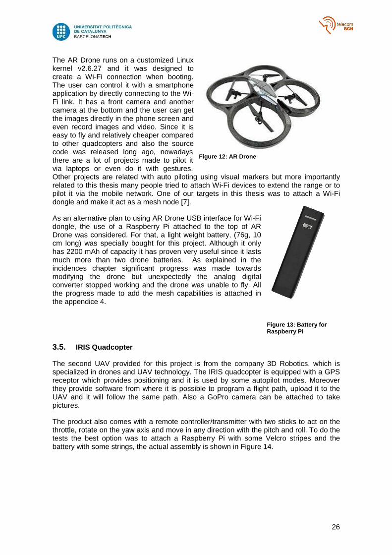
The AR Drone runs on a customized Linux kernel v2.6.27 and it was designed to create a Wi-Fi connection when booting. The user can control it with a smartphone application by directly connecting to the Wi-Fi link. It has a front camera and another camera at the bottom and the user can get the images directly in the phone screen and even record images and video. Since it is easy to fly and relatively cheaper compared to other quadcopters and also the source code was released long ago, nowadays there are a lot of projects made to pilot it via laptops or even do it with gestures. Other projects are related with auto piloting using visual markers but more importantly related to this thesis many people tried to attach Wi-Fi devices to extend the range or to pilot it via the mobile network. One of our targets in this thesis was to attach a Wi-Fi dongle and make it act as a mesh node [7].
As an alternative plan to using AR Drone USB interface for Wi-Fi dongle, the use of a Raspberry Pi attached to the top of AR Drone was considered. For that, a light weight battery, (76g, 10 cm long) was specially bought for this project. Although it only has 2200 mAh of capacity it has proven very useful since it lasts much more than two drone batteries. As explained in the incidences chapter significant progress was made towards modifying the drone but unexpectedly the analog digital converter stopped working and the drone was unable to fly. All the progress made to add the mesh capabilities is attached in the appendice 4.
3.5. IRIS Quadcopter
The second UAV provided for this project is from the company 3D Robotics, which is specialized in drones and UAV technology. The IRIS quadcopter is equipped with a GPS receptor which provides positioning and it is used by some autopilot modes. Moreover they provide software from where it is possible to program a flight path, upload it to the UAV and it will follow the same path. Also a GoPro camera can be attached to take pictures.
The product also comes with a remote controller/transmitter with two sticks to act on the throttle, rotate on the yaw axis and move in any direction with the pitch and roll. To do the tests the best option was to attach a Raspberry Pi with some Velcro stripes and the battery with some strings, the actual assembly is shown in Figure 14.
Figure 12 : AR Drone
Figure 13 : Battery for Raspberry Pi

27
3.6. Wireless Configuration Tools
To be able to configure a mesh network it is essential to use some software. In this section there is an overview of the Linux tools for wireless configuration.
• ifconfig
Although the main tool is iw, which is supposed to replace all the previous wireless configuration tools, there are still some configurations needed to be done with ifconfig. ifconfig stands for interface configuration and its purpose is to configure net interfaces, it operates at a higher level than iw and it is mainly used to assign IP addresses to each node and to enable and disable the interfaces when necessary.
• iw
iw is a command line interface (CLI) configuration utility that replaces the old wireless configuration tools such as iwconfig, iwlist, etc. It can be installed from the Linux repository, however the version that comes (3.4) is a bit outdated for our purposes, for example among other things, that version does not allow to configure the different power save modes. In this thesis was mostly used the version 3.14, although the 3.15 is already available.
Figure 1 4: IRIS and Raspberry assembly

28
3.7. Testing Tools
To perform the tests some programs were used to measure the most relevant parameters of the network, like throughput and packets loss.
• Ping
Ping is a well-known network utility that sends packets to the IP address set expecting a response. Since inside the mesh network nodes actually communicate with each other using the MAC address, the reason we also assign manually an IP address to each node is to be able to use ping because it is a quick way to check that the connection is established between two nodes and more importantly that they are able to send and receive packets.
Additionally it gives information about the packets loss and statistical information such as the minimum, maximum and average about the round trip time but only when the ping is stopped.
• Iperf/Jperf
Iperf is a network testing tool that is able to create streams of TCP and UDP packets. To use it, first it is necessary to configure one node as a server and then one or more nodes as a client, in this case the clients also need to know the IP address and the port the server is listening to be able to establish communication.
With the TCP protocol it is possible to measure the throughput of the link. Considering that TCP is a reliable protocol, all the errors and retransmissions are included in that measure, hence this is a way to measure which is the maximum throughput for the network when retransmissions are necessary.
On the other hand with UDP it is also possible to measure the throughput but since it is an unreliable protocol it sends frames without expecting acknowledgements, so it is possible to select at which rate we want to send those frames. Besides that, since the client also sends the amount of frames it had sent, the server can count how many it received and divide them to estimate the frame error rate.
Because there are a lot of configurable parameters it is cumbersome to work with it from the command line, this is why Jperf was used. Jperf uses a Java GUI (Figure 15) to facilitate the configuration of Iperf and quickly execute it. It also creates simple reports and automatically draws graphics of the results.

29
Figure 15: JPerf us er interface

30
4. Results
In this section will be shown the multiple tests performed with the devices as well as the main reason to do it, current limitations and observations made.
4.1. Raspberry Pi tests
This set of tests were performed only using Raspberry Pi devices in a single room approximately 5 meters across without obstacles neither too much interference from the environment. The main reason for that is that in previous tests made indoors, there were long fluctuations on the wireless channel that produced results with high deviation that did not match a logical behaviour.
Two nodes
This test was performed using two devices separated by about 4 meters, it is the simplest mesh possible but it is useful to compare it with future tests to observe the decline in performance.
To get a significant result each result consisted in a TCP or UDP stream during one minute to get an average over time, furthermore each one minute experiment was repeated three times to get another average.
Iperf allows the users to tune up to three parameters in a TCP connection, which are buffer length, window size and maximum segment size. To try to get a wider view of the performance the window size was the parameter selected to vary its value because it is the one that in theory can affect the most the outcome.
The window is referring to is the congestion window. TCP manages the congestion by trying to send as many frames as they fit in the window before receiving an acknowledgement. If it misses a frame, which means there is congestion, it reduces the size of that window and afterwards tries to increase it again. In theory the optimal value of that window is the product of the transmission bit rate and the round trip time or bandwidth-delay product. Since the bit rate observed with iw quickly varied, 54 Mbps was chosen because it is the maximum value since the devices support the standard 802.11n. To get the delay we can use ping, and in average around 2 or 3 ms was obtained, hence we obtain a window size of 16 KBytes. The results are in Table 2.
Figure 16 : Two nodes mesh schematic

31
As we can see the average throughput with TCP is around 8 Mbps for 2 nodes, the difference in bit rates between the three results does not seem to be significant enough to be caused by the different window sizes.
UDP offers more possibilities, we can change the traffic offered, and buffer and packet size. Additionally in the report it gives we can observe the traffic sent, the jitter which is a measure of the absolute delay of the frames and the loss probability. For these experiments was chosen only to vary the traffic offered because it is the most meaningful parameter. Instead of always choosing the same set of values of offered traffic, only the ones that the mesh supports in that configuration.
UDP Traffic offered 6 Mbps 8 Mbps 10 Mbps
Traffic sent 5504 Kbps 7482 Kbps 9522 Kbps
Traffic received 5496 Kbps 7471 Kbps 9522 Kbps
Losses 0.14 % 0.15 % 0 %
Jitter 10.612 ms 6.600 ms 0.694 ms
Table 3: Two nodes UDP
Here we can see some kind of inconsistency because with 10 Mbps there should not be fewer losses than with less traffic, but there is not that much deviation so we can attribute it to fluctuations. Additionally, high jitters are also a result from that.
Three nodes
Here a mesh was formed by putting three devices one after another like in Figure 13, iperf was running from one end to the other so we expect a drop of performance due to retransmissions. Here are the TCP results:
TCP Window Size 12 KB 16 KB 20 KB
Throughput 7859 Kbps 8103 Kbps 8445 Kbps
Table 2: Two nodes TCP
Figure 17 : Three nodes mesh schematic

32
Since there are 3 nodes, the average delay obtained with ping was around 4 ms, so the optimal window size falls on those numbers. As we can see again the window size does not seem to have any effect but the performance compared with two nodes dropped by half.
Also in UDP we can observe the performance declining, still supports 4 Mbps well but if we increase the traffic offered the source cannot keep the pace and the losses increase.
Four nodes
Another device is added to the mesh, notice that the distance between the end nodes is not increasing, instead the nodes are added in between. It was done this way because of the limitations of the scenario and because the frame management and retransmission is
TCP Window Size 20 KB 24 KB 28 KB
Throughput 4385 Kbps 4080 Kbps 4041 Kbps
Table 4: Three nodes TCP
UDP Traffic offered 4 Mbps 6 Mbps 8 Mbps
Traffic sent 3998 Kbps 5776 Kbps 7134 Kbps
Traffic received 3952 Kbps 5641 Kbps 6682 Kbps
Losses 1.15 % 2.33 % 6.33 %
Jitter 1.168 ms 2.049 ms 4.250 ms
Table 5: Three nodes UDP
Figure 18 : Four nodes mesh schematic

33
more notable than the delay due to the distance and this way the wireless medium of all links is roughly the same.
In this case the ping was larger so the optimal window size falls in those values. As expected the throughput decreased again around 2.5 Mbps.
For UDP the net is able to keep the pace of the traffic offered until 6 Mbps, but the losses quickly become unacceptable.
Summary
Since we did not have more Raspberry Pi devices, this type of tests could not be extended beyond 5 nodes, but we should have enough to observe the main trend.
Even if in TCP the congestion window size was changing, we conclude that that parameter is not relevant, it was also verified with much higher sizes and it did not have any effect.
For UDP although for two nodes different values of traffic offered were used we can be sure that it could support 4 Mbps as well practically without losses.
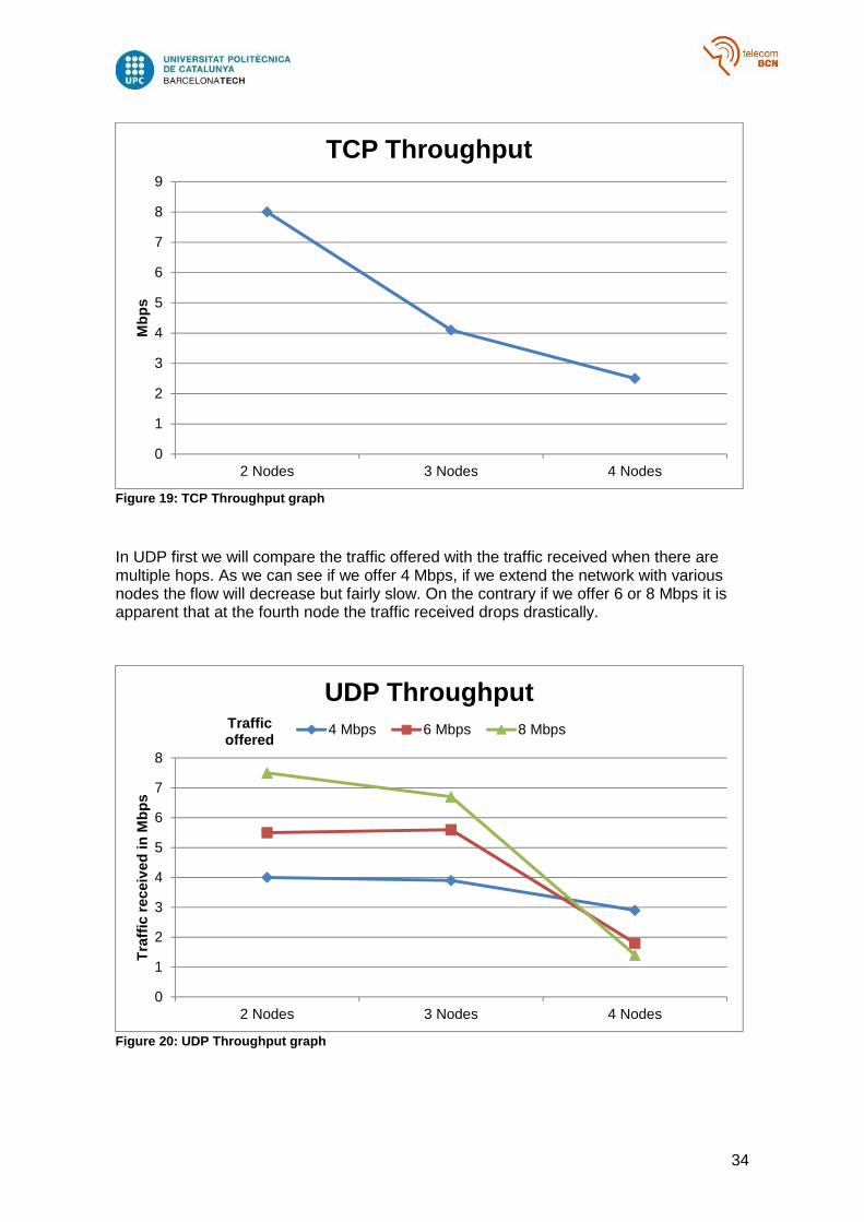
In Figure 15 we can observe the tendency, as more hops are added the throughput tends to zero in what could be an exponential decay but we do not have enough data to infer that.
TCP Window Size 28 KB 32 KB 36 KB
Throughput 2959 Kbps 2533 Kbps 2249 Kbps
Table 6: Four nodes TCP
UDP Traffic offered 4 Mbps 6 Mbps 8 Mbps
Traffic sent 3981 Kbps 5194 Kbps 5746 Kbps
Traffic received 2866 Kbps 1818 Kbps 1436 Kbps
Losses 28 % 65 % 75 %
Jitter 1.653 ms 13.069 ms 18.503 ms
Table 7: Four nodes UDP
34
Figure 19: TCP Throughput graph
In UDP first we will compare the traffic offered with the traffic received when there are multiple hops. As we can see if we offer 4 Mbps, if we extend the network with various nodes the flow will decrease but fairly slow. On the contrary if we offer 6 or 8 Mbps it is apparent that at the fourth node the traffic received drops drastically.
Figure 20: UDP Throughput graph
0
1
2
3
4
5
6
7
8
9
2 Nodes 3 Nodes 4 Nodes
Mbp
sTCP Throughput
0
1
2
3
4
5
6
7
8
2 Nodes 3 Nodes 4 Nodes
Tra
ffic
rece
ived
in M
bps
UDP Throughput4 Mbps 6 Mbps 8 MbpsTraffic
offered

35
We can see the same effect by looking at the losses, at the fourth hop they increase drastically as shown in Figure 17.
Figure 21: UDP losses graph
Power Save Mode
The next step is to test the network using power save mode using TCP and UDP as well but varying parameters relevant to power save mode.
In this case for this and the following tests only 2 nodes in light sleep were used. For TCP high values for the congestion window were chosen to make the nodes buffer its frames.
As we can see the throughput got reduced almost a factor of 10 comparing with first test in active mode.
With UDP happens as expected, the net can send the traffic offered but there will be a lot of losses.
0%
10%
20%
30%
40%
50%
60%
70%
80%
2 Nodes 3 Nodes 4 Nodes
Loss
es
UDP Throughput4 Mbps 6 Mbps 8 MbpsTraffic
offered
TCP
Window Size 240 KB 280 KB 320 KB
Throughput 798 Kbps 856 Kbps 860 Kbps
Table 8: Power Save Mode TCP

36
As we can see the net in power save mode using UDP barely supports a throughput of 1 Mbps, if we try to increase it the losses become overwhelming.
Awake Window
As discussed previously the Awake Window is a very significant parameter in power save mode.
For TCP a default congestion window of 320 Kbytes was chosen and the test was repeated varying the size of the Awake Window, notice that that size is in TU (Time Units), a unit of time equivalent to 1024 µs that is used because it is much easier for hardware to work with powers of 2 than in powers of 10 like 1000.
As we can see, in this situation the Awake Window is totally irrelevant because since it is a communication where both stations are in light sleep mode when they have to transmit frames the PSP takes precedence and keeps the stations awake a longer time than the Awake Window.
For UDP occurred the same, the test was performed sending 2 Mbps:
UDP Traffic offered 1 Mbps 2 Mbps 4 Mbps
Traffic sent 1000 Kbps 2000 Kbps 3961 Kbps
Traffic received 917 Kbps 1160 Kbps 1228 Kbps
Losses 8.3 % 42 % 69 %
Jitter 16.322 ms 8.021 ms 9.898 ms
Table 9: Power Save Mode UDP
TCP Awake Window 1 TU 10 TU 100 TU
Throughput 1068 Kbps 1072 Kbps 1063 Kbps
Table 10: Awake Wi ndow TCP

37
It behaved just like the previous UDP test, with an offered traffic of 2 Mbps we obtain around 50% of losses.
Beacon Interval
Generally speaking sleeping stations are paced by their own beacons and by their neighbour’s beacons. A change in the period they send the beacons should modify the amount of time they are awaken, consequently modifying the transmission rate.
For TCP a congestion window of 320 Kbytes was chosen, notice that by default the beacon interval is set to 1000 TU.
Now we have some interesting results, for a value of 1000 TU (the default) we obtain the same value as before but halving the beacon interval which means doubling the activity we obtain double the throughput and the other way around when the beacon interval is doubled to 2000 TU.
With UDP an offered traffic of 2 Mbps was used again.
UDP Awake Window 1 TU 10 TU 100 TU
Traffic sent 1999 Kbps 2000 Kbps 1999 Kbps
Traffic received 920 Kbps 900 Kbps 880 Kbps
Losses 54 % 55 % 56 %
Jitter 18.921 ms 11.582 ms 9.069 ms
Table 11: Awake Window UDP
TCP Beacon Interval 500 TU 1000 TU 2000 TU
Throughput 1996 Kbps 973 Kbps 432 Kbps
Table 12: Beacon Interval TCP

38
These results need some discussion, for the default value we obtained more or less the same result than the first power save UDP test, although it seems that the channel was especially good during this test. For a value of 1000 TU we obtain 38% of losses, doubling the beacon interval produced roughly double the losses and half the traffic received. It happens because the receiving station is half the time active, consequently there is more time in a period where the frames get lost because the source is not expecting acknowledgements.
On the other hand if we halve the beacon interval we obtain much fewer losses than 19%, which is half of 38%. The reason is that we are only offering 2 Mbps, hence we cannot obtain double the bit rate for a 1000 TU, which would be around 2500 Kbps. So we obtain less traffic but with less losses.
4.2. UAV Tests
The following tests were performed in an open space using the IRIS quadcopter. A Raspberry Pi and its battery was attached over the drone to perform the following tests.
Three nodes
To begin with a simple test was created forcing a topology in line like before with the drone in between moving around the scenario. But now the tests were only performed during 30 seconds for logistic reasons. The scenario was a public place open enough to fly the drone and have two computers separated about 15 meters. The tests were shorter to save battery time of the UAV to be able to do to as many as possible because it was cumbersome to set up the scenario.
UDP Beacon Interval 500 TU 1000 TU 2000 TU
Traffic sent 2000 Kbps 2000 Kbps 1997 Kbps
Traffic received 1903 Kbps 1240 Kbps 619 Kbps
Losses 4.86 % 38 % 69 %
Jitter 9.989 ms 10.258 ms 11.340 ms
Table 13: Beacon Interval UDP

39
For TCP 3 tests of 30 seconds were done for each window size, like before the window size does not affect. And we obtain a throughput around 6 Mbps
It is actually better than the three test node done inside, it could be because with an open field with few obstacles the nodes do not have to deal with multiple reflections, and consequently there is less interference.
For UDP we obtain much better results than in the closed environment, it could be because there was not multipath, but it might be possible that the network reconfigured itself and the connection was directly computer to computer.
Overall these tests were difficult to perform and be consistent with them for multiple reason, First due to the fact that there is a learning curve to pilot the drone, many tests had to be invalidated because obviously it was better to land the drone before the possibility to crash it, also because of the Raspberry Pi and battery attached seem to make the drone drift in a given direction although the accelerometer was recalibrated. Moreover sometimes the wind can be dangerous making it harder to control it.
Adding to all of that because it is necessary to focus on piloting the drone it is impossible to check at the same time how the test is doing, additionally it is advisable to keep an eye on the other computer because after all it was a public place.
TCP Window size 24 KB 48 KB
Throughput 6138 Kbps 6057 Kbps
Table 14: UAV 3 nodes TCP
UDP Offered 4 Mbps 8 Mbps 16 Mbps
Throughput 3917 Kbps 6309 Kbps 7868 Kbps
Traffic received 3891 Kbps 6245 Kbps 7669 Kbps
Losses 0.65 % 1.02 % 2,52 %
Table 15: UAV 3 nodes UDP
Figure 22: UAV mesh scenario

40
Distance
This test is interesting to see the theoretically drop of transmission rate when the drone flies away in a straight line from the node. The tests were performed two or more times during 60 seconds.
Figure 24: UAV TCP Throughput graph
In this case the graph goes as expected, the two colours represent two separate tests and the X-axis represents the time in seconds, each test was done during 60 seconds. There is a point where the transmission rate drops but the main problem is the quantization. As observed in the data in this case it only transmits multiples of 128 Kbytes of data per second, which is equivalent to 1049 Kbps so only obtains values multiple of that. It seems more like a software error that physical behaviour. But at the same time the Raspberry Pi attached was configured in such a way that it gets configured as a mesh point automatically when it boots without any input.
Seeing this was thought that maybe it was an issue of antenna directivity because when flying away the Wi-Fi dongle of the Raspberry Pi points at the opposite direction of the other station, however the radiation diagram of the antenna is unknown. There was the possibility to pilot the drone backwards so the USB dongle is pointing to the station but it
Figure 23 : UAV distance mesh scenario
0
500
1000
1500
2000
2500
3000
3500
0 10 20 30 40 50 60 70
Kbp
s
TCP Throughput

41
was dangerous to pilot it manually this way due to having the controls reversed from the point of view.
The next idea was to perform the test inversely, taking off far away and finishing next to the station, but the same happened and did not contribute to anything at all.
Afterwards was performed the same test but with UDP and it actually got worse and does not seem to make sense at all. The offered traffic selected was 2 Mbps.
The peaks do not seem to be an isolated event, since they are impossible because we are only offering 2 Mbps, they must be produced by software errors, it seems like the software counts in the same single second the data transmitted during the previous seconds but somehow it counts them as 0.
To conclude, this UDP tests were poor performed and we cannot extract information from them, additionally it is only shown the offered traffic because the iperf server (the drone) did not provide the usual report at end of test. It just means that the link was very poor, it could be done the other way around with the client in the drone but then it becomes very cumbersome having to access the Raspberry Pi at the beginning of each test and quickly take off.
However another thing to take into consideration is that the link to control the drone also works at 2.4 GHz, the same than the mesh. Also the Raspberry Pi is very close to the receiver of the drone and there might be a lot of interferences because for safety reasons the UAV was piloted always at a short range.
This type of test it also difficult to perform if needed to be done in a consistent way, because the speed of the drone is unknown and it should be the same more or less every time, also when piloting the UAV accidently or because of the wind it may gain altitude and maybe get a better line of sight resulting in better transmission rate. Also since it is not possible to change the transmitting power of the USB dongles the distance needed to lose the connection is very large, reducing the power could scale this test and make it more consistent and repeatable.
0
2000
4000
6000
8000
10000
12000
0 10 20 30 40 50 60 70
Tra
ffic
sent
in K
bps
UDP Throughput
Figure 25 :UAV UDP Throughput graph

42
Here conclude all the tests performed for the thesis, sadly there was not enough time to try to improve these tests and do them properly or at least discover the source of error. Another test was planned to do regarding the time it takes a moving node to change of peering link like in the next figure
Ideally if we send a stream form the bottom node to the drone at the beginning we would obtain a stable connection through the left node, depending on the distances when the drone is in the middle it might lose the connection or at least reduce the bit rate until it approaches the right station when it will recover the throughput but now the path will be through the right station. We could even vary some parameter to see if it changes the time it takes to connect to the new station.
Figure 26 : UAV peering link mesh scenario

43
5. Budget
Although the aim of this project was to do an evaluation of an already existing wireless protocol, not to develop a new idea or prototype, it required an extensive usage of several components and devices.
Item Cost/Unit Number of units Cost
Raspberry Pi Model B 26 € 4 104 €
SD Cards 5 € 4 20 €
WI-PI USB adapter 10 € 4 40 €
Penguin USB adapter 18 € 2 36 €
Raspberry Pi Battery 26 € 1 26 €
Parrot AR Drone 73 € 1 73 €
Molex 10-pin connector 1,54 € 1 1,54 €
2mm pin connector 1,45 € 1 1,45 €
AR Drone Toolkit 13 € 1 13 €
IRIS Quadcopter 550 € 1 550 €
IRIS Extra battery pack 26 € 1 26 €
Total Cost 891 €
Table 16: Budget item list This is the purchase value of the most important items for this project, although most of them were already given from the department. Some of these values were converted from US$ or UK₤ and shipping costs are not included, moreover since this version of the AR Drone is discontinued this value is taken from a non-official online vendor. Also the AR Drone Toolkit was not strictly necessary for the project but it was purchased to try to repair it.
Number of hours Cost/hour of junior engineer Total cost 300 8 € 2400 €
Table 17: Total hour costs So at the end, developing this project would cost 3300 €, always considering the need to purchase a second UAV.

44
6. Environment Impact
Although objectively the use of drones does not suppose a negative impact on the environment, it can be argued that they can be hazardous devices if not piloted correctly and safety measures have to be taken into account like the effect of wind, obstacles in the field and of course people and animals should not be harmed.
Moreover these UAVs use Lithium Polymer batteries, which are adequate for this type of devices because they are light weight but they are especially dangerous if they overcharge, overdischarge, overheat or get crushed or punctured because they might get on fire. They are usually well placed in the UAVs and protected by the hull but they cannot be left charging without anyone looking for the same reasons.
Figure 27 : Iris Li -Po battery pack

45
7. Conclusions and future development:
To sum up, in my opinion this project suffered greatly from time constraints, the set of Raspberry Pi tests were consistent and provided valuable information to the thesis, and it might be possible to extrapolate some kind of model to explain the behaviour. However because looking back now the first part of the project went fairly slow and because of the AR Drone malfunction the second part of the project got very reduced and there was not enough time to identify errors and develop a good methodology to perform the various test with the UAV.
It is also relevant that the ideal conditions to do tests with the UAV are difficult to achieve, considering that an open field is needed with a less obstacles as possible, without people and neither pets. Moreover there will not be power outlets there, so the time is constrained by the battery life of all devices. The impossibility to reduce the transmitting power of the USB dongles requires great distances as well, then since the directivity of the antennas is unknown, for a future development someone might consider to use a dipole antenna or another omnidirectional one and use as well the 5 GHz band to mitigate interferences. Although finding a device with those characteristics and also compatible with mesh might be difficult. Unfortunately seems that the Raspberry Pi attached to the IRIS blocks the GPS signal which would facilitate flying it in a defined pattern multiple times to repeat the tests and also to calculate real distances and speeds.
Another approach for a future development I recommend using a Parrot AR Drone 2.0, physically is more or less the same but it runs a kernel v2.6.32 which would directly solve some of the incompatibilities and seems more flexible in terms of adding or removing modules. Also it already comes with a proper USB connector so future projects would not have to deal with obsolete connectors. But of course I do not know for sure if it could incorporate mesh capabilities.
Thinking further once obtained the behaviour of the network with one UAV, the next step would be using two UAVs but I think I would require at least two people to develop that, although the actual tests of this project I recommend them to do it with two people.

46
Bibliography
[1] Jerome Henry. “802.11s Mesh Networking” November 2011. Certified Wireless Network Professional.
[2] Guido R. Hiertz, Dee Denteneer, Sebastian Max, Rakesh Tahori, Javier Cardona, Lars Berlemann, Bernhard Walke.”IEEE 802.11s: The WLAN Mesh Standard”. IEEE Wireless Comunications 2010.
[3] Mirza Nazrul Alam, Riku J¨antti, Jarkko Kneckt, and Johanna Nieminen. “Performance Analysis of the IEEE 802.11s PSM”. Journal of Computer Networks and Communications, volume 12, Article ID 438654, DOI:10.1155/2012/438654.
[4] Luis Javier Sánchez Cuenca, “802.11s based Wireless Mesh Network (WMN) test-bed”. Master Thesis, Lulela University of Technology, Department of Computer Science and Electrical Engineering, March 2010.
[5] https://github.com/cozybit/open80211s/wiki/HOWTO
[6] https://github.com/cozybit/open80211s/wiki/Mesh-Powersave-Implementation-Notes
[7] http://taghof.github.io/Navigation-for-Robots-with-WIFI-and-CV/

47
Appendices
A. Usage of ifconfig/ iw [5]
• ifconfig
ifconfig always works with interfaces, if you simply type:
$ ifconfig
All the recognized interfaces will be printed with some information like its IP and MAC addresses. For simplicity we will suppose that we want to configure the interface wlan0.
$ ifconfig wlan0 192.168.1.106/24
$ ifconfig wlan0 hw ether a8:54:b2:42:8e:fd
The first command will configure wlan0 with the corresponding IP address with a network mask of 24 bits. If necessary the MAC address can also be set with the second command.
$ ifconfig wlan0 down
The previous command is important because disables the operation of the interface, which is needed to configure it as a mesh point for example. Whenever the system complains that an interface is busy when configuring something it means that it has to be brought down previously. On the contrary to enable it again simply type:
$ ifconfig wlan0 up
• iw
To install the most recent version simply download and extract the latest .tar file with these commands:
$ wget https://www.kernel.org/pub/software/network/iw/iw-3.15.tar.xz
$ tar xf iw-3.15.tar.xz
To be able to install it, it is necessary to have a pair of libraries installed:
$ sudo apt-get install libnl-3-dev libnl-genl-3-dev
$ cd iw-3.15/
$ make
$ sudo cp iw /bin

48
These commands will install the libraries needed, compile iw and make a copy of it into the bin directory which allows to run the software from any folder simply by typing iw, otherwise you would need to be inside the extracted folder and type ./iw.
iw is a powerful configuration tool, it has a lot of functionalities. In this section only the more relevant will be explained.
First of all, to know the available interfaces it can work with type:
$ iw dev
dev stands for devices, which are the same as interfaces, this command will print them. For the sake of the example we suppose that we want to work with wlan0.
$ iw wlan0 info
The previous command will show the information of the interface selected, however iw also works in the physical layer and each physical device can hold multiple interfaces performing different tasks. The physical devices are labelled with phy.
$ iw phy
$ iw phy0 info
These commands, like the previous ones show the information of all physical devices and one in particular. It is useful to check that information because it prints the exact capabilities of the device like frequency channels, bitrates and commands supported.
To add another interface type the following command:
$ iw wlan0 interface add mesh0 type managed
It will add an interface called mesh0 next to wlan0 (in the same physical device). The type also has to be specified, for now we set it to managed which is the default one.
After bringing the interface mesh0 down with ifconfig, we can type:
$ iw mesh0 set type mesh
It will configure that interface as a mesh point (instead of mesh can also be mp), there are other configuration types like monitor but it is not relevant now.
Once the type is selected and it has in IP address assigned we can join the mesh network.
$ iw mesh0 mesh join meshnet
It will have joined a mesh network by the name of meshnet, other nodes should join the mesh with the same name.

49
If it is successful, when printing the information of that interface, it should look like this:
Interface mesh0 Ifindex 10 Wdev 0x1
Addr a8:54:b2:42:8e:fd Type mesh point Wiphy 1
Channel 1 (2142 MHz), width: 20 MHz (no HT), center 2412 MHz
Once we have more nodes in the mesh and a link is established, we can get information about them by typing:
$ iw mesh0 station dump
Station 00:03:7f:10:4e:0c (on mesh0) inactive time: 4 ms rx bytes: 836333
rx packets: 21553 tx bytes: 32581 tx packets: 543
tx retries: 345 tx failed: 15 signal: -37 dBm
signal avg: -39 dBm Toffset: -2479495726 us tx bitrate: 54.0 MBit/s
rx bitrate: 12.0 Mbit/s mesh llid: 14694 mesh plid: 52785
mesh plink: ESTAB mesh local PS mode: ACTIVE mesh peer PS mode: ACTIVE
mesh non-peer PS mode: ACTIVE authorized: yes authenticated: yes
preamble: long WMM/WME: yes MFP: no
TDLS peer: no
Here we can see its activity in terms of packets transmitted and received, the signal we get, which is related to the distance, the bit rate observed is unreliable because it is not a stable value. If the peer link is established it indicates it with ESTAB in mesh plink. Moreover, here we can also see the power save (PS) modes but it will be explained in more detail afterwards.
If the peer link is established we should be able to communicate, by doing a ping to the IP address of the other node:
$ ping 192.168.1.105 –c 2

50
PING 192.168.1.105 (192.168.1.105) 56(84) bytes of data. 64 bytes from 192.168.1.105: icmp_seq=1 ttl=64 time=8.85 ms 64 bytes from 192.168.1.105: icmp_seq=2 ttl=64 time=3.42 ms
Observe that the first ping is always more delayed because the process of finding a path to the destination takes place when requesting it.
When the path is discovered the table containing the paths is updated, to see it we have to type:
$ iw mesh0 mpath dump
DEST ADDR NEXT HOP IFACE SN METRIC 00:03:7f:10:4e:0c 00:ff:f3:a0:24:bd mesh0 51 25507
QLEN EXPTIME DTIM DRET FLAGS
0 3341812736 100 0 0x4
Remembering that the mesh works at the MAC layer, as an example this shows that to reach the node with the MAC address 00:03:7f:10:4e:0c we have to send frames to 00:ff:f3:a0:24:bd which in turn it will send them to other stations. The other columns display information about the path itself like the freshness of the path, the expiration time or the metric, which represents the theoretical cost of the path. With this information the nodes dynamically discover and reassign new paths, looking for the better one.
On the contrary if one wants to manually determine a path there is also a commands to do it:
$ iw mesh0 mpath del 00:03:7f:10:4e:0c
It will delete the path entry to that destination, and to make a new entry:
$ iw mesh0 mpath new 00:03:7f:10:4e:0c next_hop 00:0f:13:38:11:06
It is important to know that this command only configures the path to the next hop in the mesh, it is necessary to make sure that from there the network can get to the destination.
These commands are useful to force a specific topology instead of relying in the protocol itself.
Furthermore, if we have an interface configured as a mesh node we can access and configure a set of parameters related to the mesh operation, to show them and their values type:
$ iw mesh0 get mesh_param
It will display the list of parameters, in general they relate to the HWMP, root mode operation or power save mode. They are used to impose restrictions on the mesh or make the protocol operate at a different timing. As an example, one of the more useful parameters is the one that does not allow to establish a peer link below a threshold, if we type:
$ iw mesh0 set mesh_param mesh_rssi_threshold=-60

51
It will cause that the interface mesh0 will not establish a new peer link if the signal received is below -60 dBm. Lastly, to configure the power save mode there are two ways, one is to establish the default mode setting the parameter mesh_power_mode to light or deep and the other is to configure it towards another node.
$ iw mesh0 station set 00:03:7f:10:4e:0c mesh_power_mode light
Now mesh0 will be in light sleep mode towards the node with that MAC address. If we type again station dump we will see something like that:
Station 00:03:7f:10:4e:0c (on mesh0)
. .
mesh local PS mode: LIGHT mesh peer PS mode: ACTIVE
mesh non-peer PS mode: ACTIVE . .
mesh local PS mode shows that we are in light sleep towards that station, mesh peer refers to the sleep mode of that station towards us, in this case is active. mesh non-peer refers to the sleep mode of that station towards nodes that are more than one hop away.
Here concludes the explanation of iw, for more detailed explanations and advanced commands visit http://wireless.kernel.org/en/users/Documentation/iw

52
B. Raspberry Pi kernel cross compilation
For this project it was necessary to compile a new kernel for the Raspberry Pi. Because it was not ready directly from updates it has to be done via cross compilation. A Cross compiler is a compiler capable of creating executable code for another platform , in this case it was done from a laptop using an Intel processor of 64 bits to a Raspberry Pi, which uses a 32 bits ARM processor .
First of all we need the kernel code source, to do that we will use git, if it is not installed type:
$ sudo apt-get install git
To get a specific branch we will type the following replacing X by the corresponding number
$ git init
$ git fetch git://github.com/raspberrypi/linux.git rpi-3.X.y:refs/remotes/origin/rpi-3.X.y
$ git checkout rpi-3.X.y
Or it is also possible to download it from the git website. Then we need the cross compiler, we will use the one that they recommend:
$ git clone https://github.com/raspberrypi/linux.git
Before continuing there is a step often overlooked, since we are compiling a kernel for a 32 bits system from a 64 bits one we need some
specific libraries that sometimes are not mentioned.
For Ubuntu 12.04 it is enough to install this:
$ sudo apt-get install ia32-libs For newer systems this library does not longer exists, instead we have
to install multiple ones: $ sudo apt-get install libc6:i386 libgcc1:i386 gcc-4.6-base:i386 libstdc++5:i386 libstdc++6:i386 lib32z1 lib32ncurses5 lib32bz2-1.0
Next we need to configure the compilation of the kernel, to do that enter the downloaded kernel directory, then set some external variables to indicate that we want to cross compile:
$ export CCPREFIX=/usr/bin/arm-linux-gnueabi-bcmrpi_cutdown_defconfig
$ make ARCH=arm CROSS_COMPILE=${CCPREFIX} menuconfig
The CCPREFIX variable indicates the path to the binary that cross compiles, when configure the kernel we indicate the type of processor with the variable ARM and the cross compiler with the variable CROSS_COMPILE. With the previous command we will have access to the configuration menu, when it is done save the .config file. To work with mesh capabilities is imperative to enable the mac80211 module and which should be
53
already set by default and also enable the wireless drivers we plan to use. Then in the same directory to build the kernel and its modules we will type:
$ make ARCH=arm CROSS_COMPILE=${CCPREFIX}
$ make ARCH=arm CROSS_COMPILE=${CCPREFIX} modules
It will directly build all the necessary, the fully built kernel should be in arch/arm/boot/Image. It is recommendable to keep the old kernel just in case the new one fails. To do that after inserting the SD card there should be a partition called boot, there rename the file kernel.img to kernel_old.img. And copy the kernel built and name it kernel.img. The device will boot with that new image.
Then we just need to transfer the modules built, to do that type the following commands
export MODULES_TEMP=~/modules
make ARCH=arm CROSS_COMPILE=${CCPREFIX} INSTALL_MOD_PATH=${MODULES_TEMP} modules_install
The first one will create a directory where all the modules will be installed, inside there will be a directory called lib. Finally we just need to copy the contents of this directory inside the /lib directory of the SD card.
Then the Raspberry should boot with the new kernel, this appendice follows the explanation made in this page: http://elinux.org/RPi_Kernel_Compilation

54
C. Connection from laptop to Raspberry Pi
To be able to connect the Raspberry Pi to a laptop a static IP address for the Ethernet port was set to each SD card. To configure it simply use a computer with a SD card reader and insert the Raspberry Pi card, there will be a partition called BOOT where among other things the kernel image is present. There has to be a file called cmdline.txt where there is some configuration for the kernel when it boots, to configure the IP address simply type the following at the end of the file with the corresponding IP (if in the computer the IP address is set to automatic it should be set to 169.254.XX.XX), for example:
ip=169.254.0.2
This line will configure the Ethernet port with this IP when the system boots. With that address set we can plug an Ethernet cable connecting a laptop with the Raspberry Pi and work with a remote SSH connection from the laptop. To do that, follow the next instructions for each operating system.
• Windows
First of all to Properties and then on the properties “Internet Protocol Version 4 (TCP/IPv4)”.
There you can set an automatic IP assigning or a static one. If it set to automatic the previous example should work. Secondly a couple of programs are needed: Xming to be able to see the actual desktop window and all the graphical interfaces of the Raspberry Pi and PuTTY to establish the SSH connection. If you do not have them you can download from here:
Xming: http://sourceforge.net/projects/xming/
PuTTY: http://www.putty.org/
Figure 28 : Windows’ IP configurat ion
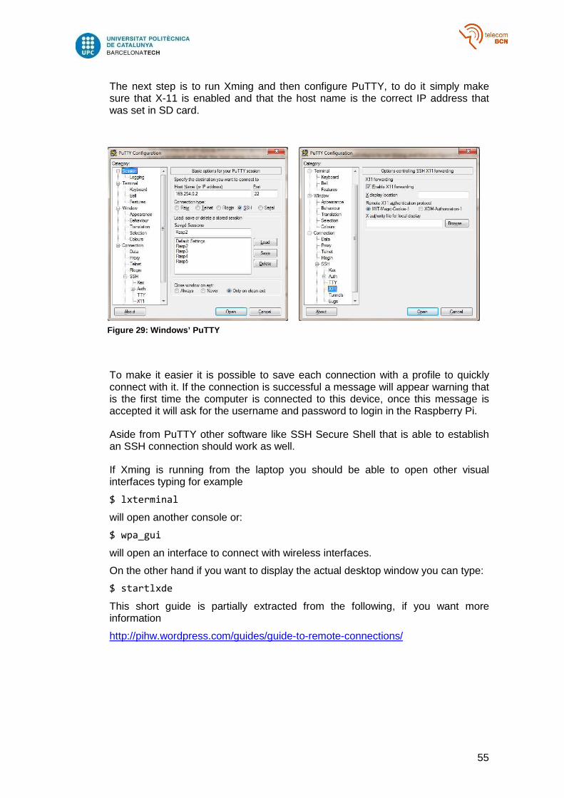
55
The next step is to run Xming and then configure PuTTY, to do it simply make sure that X-11 is enabled and that the host name is the correct IP address that was set in SD card.
To make it easier it is possible to save each connection with a profile to quickly connect with it. If the connection is successful a message will appear warning that is the first time the computer is connected to this device, once this message is accepted it will ask for the username and password to login in the Raspberry Pi.
Aside from PuTTY other software like SSH Secure Shell that is able to establish an SSH connection should work as well.
If Xming is running from the laptop you should be able to open other visual interfaces typing for example
$ lxterminal
will open another console or:
$ wpa_gui
will open an interface to connect with wireless interfaces.
On the other hand if you want to display the actual desktop window you can type:
$ startlxde
This short guide is partially extracted from the following, if you want more information
http://pihw.wordpress.com/guides/guide-to-remote-connections/
Figure 29 : Windows’ PuTTY

56
• Ubuntu
Using Ubuntu to connect remotely to the Raspberry Pi might be easier. If the IP address on the SD card is already configured then it is necessary to make sure that the IP address and the mask of the Ethernet port of the laptop matches the one on the Raspberry Pi. To check that type:
$ ifconfig eth0
This will show all the information related to the Ethernet interface, including the IP address. To change the address you will probably have to be superuser hence type for example:
$ sudo ifconfig eth0 169.254.0.1/24
This will set this IP address to the Ethernet port with a mask of 24 bits. Following the previous example this will match the address of the Raspberry Pi. To be sure it is correct a ping between the two machines should be successful.
Then to establish the SSH connection, following the example, type:
$ ssh -X [email protected]
It will try to establish a ssh connection to that IP address with user “pi” which is the user by default on the Raspberry Pi. The –X parameter means that X-11 forwarding is enabled so it will allow seeing the graphical interfaces like in Windows. The first time a warning will appear saying that is the first time it is connected to this device, once accepted it will ask for the password for the Raspberry Pi and you will be granted access to the device.
To be able to see the actual desktop the previous approach does not seem to work, instead it is possible to use VNC which stands for “Virtual Network Computing”, which is software that allows sharing the desktop window.
First it is needed to install the VNC server to the Raspberry Pi:
$ sudo apt-get install tightvncserver
Next, it is necessary to run the server on the Raspberry Pi:
$ vncserver
There are some options like screen size or colour when running the server but the default should work. Then you will be asked to create a password for VNC login.
On the other side, to install the VNC client in the laptop:
$ sudo apt-get install xtightvncviewer
Once done to run the viewer you need to type the IP address of the server and the port they are communicating with:
$ vncviewer 168.254.0.2:5901

57
This guide is partially taken from a website, for more information check:
http://mitchtech.net/vnc-setup-on-raspberry-pi-from-ubuntu/

58
D. AR Drone
To connect devices to the AR Drone we only have one available port at the bottom, which is directly connected to the motherboard. Unfortunately it a uncommon connection formed by 7 pins, each one separated by 2 mm, whereas in the most common standard the pins are separated by 2,54 mm so they will not fit.
The first step is to assemble a cable that connects this port to a female USB port where we can plug any USB device. In Figure 23 it is shown the correspondence between the USB cables and the pins.
As seen in the picture, a connector by the name of Molex 511100850 is needed, but because it was only available online in larger quantities and the shipping delay was not affordable at the moment, it was decided that it was better to assembly the cable manually with other pieces. However connectors with their pins separated by 2 mm were not available and only one could be found at a single store. Although it was not the best fit and required precise welding at the end it could work. Figures 24 and 25 show the final result.
Figur e 31: Detail of the connector
Figure 30 : USB pinout

59
Actually the drone’s USB port is only meant to be used for flashing purposes and it is disabled by default. To enable it several steps must be taken, first of all the port driver has to be edited to enable the host mode, then the driver has to be cross compiled and uploaded to the drone and finally a I/O pin on the drone has to be configured.
To modify the port driver we need the kernel sources, luckily it can be downloaded in the following website: https://projects.ardrone.org/documents/show/19. There are only a few changes needed to be done in the code, the file to be edited is in “drivers/parrot/usb/dwc_otg/dwc_otg_driver.c”, in short only is needed to comment out the lines 236 and 237which are:
params->ctrl_mode = info->ctrl_mode;
params->vbus_detection = info->vbus_detection;
Commenting it will prevent the port to be configured as DEVICE_ONLY which would means that it would act like a peripheral device, not being able to act on the USB attached. Preventing it lefts the port configured as OTG_HOST_DEVICE, OTG stands for On-The-Go and it means that it can act like a host or like a device. Nowadays most devices implement that protocol. Additionally it was found that line 135 has to be changed to:
.overcurrent_pin = -1
Now to cross compile the driver we need to download a cross compiler. The AR Drone has a ARM9 processor, assuming that in a computer we have a x86 the authors of the master thesis already gave a link to a cross compiler made by CodeSourcery, a leading provider of tool chains. However they were bought by a company named Mentor Graphics. To download the cross compiling tool chain, follow the instructions from: http://www.nas-central.org. It is only needed to copy a script and execute it, and it will install all the necessary tools.
Now go to the AR Drone kernel directory and execute:
Figure 32 : The whole cable

60
$ codesourcery-arm-2011.03.sh
$ make ARCH=arm CROSS_COMPILE=arm-none-linux-gnueabi- menuconfig
The codesourcery script allows the user to enter a cross compiling environment where some paths and variables are edited to make it easier. The second command will initiate the configuration menu for the kernel, in the link where the kernel can be downloaded they also provide the default configuration file for the kernel but in this case we have to add as a module the following one:
"System Type -> Parrot Drivers -> PARROT6 USB driver (Synopsys)".
In the thesis they also point to the modules needed to attach a USB storage on the drone but it is out of the scope of this project. Once the kernel configuration is saved it is time to build the modules.
$ make ARCH=arm CROSS_COMPILE=arm-none-linux-gnueabi- modules
This should, generate a module by the name of dwc_otg.ko.To upload it we need to connect to the drone, to do it connect to its Wi-Fi and initiate a FTP pointing to its IP address.
$ ftp 192.168.1.1
Transfer the dwc_otg.ko file and connect via telnet.
$ telnet 192.168.1.1
With telnet we have full access to the drone’s files. The files transferred via FTP are always stored in /data/video, go there and before anything type:
# gpio 127 -d ho 1
# gpio 127 -d i
Those commands activate the pin number 127 as an input, which is necessary for the USB driver to work.
Now it simply type
# insmod dwc_otg.ko
And the module should be installed, to confirm it dmesg prints several lines informing that the USB port is activated.
For configuring mesh capabilities as explained in this thesis we need iw. Some effort was put into trying to cross compile it but luckily it can be found already compiled on the web, but also its library dependencies have to be downloaded as well.
You can get iw from here https://packages.debian.org, but it is essential to choose the armel download. The same for libnl-3-200 and libnl-genl-3-200.

61
To run iw is necessary to move the libraries to the /lib folder and make iw executable. The program prints all the commands as usual but it seems unable to find the AR Drone Wi-Fi device.
The next step is to transfer the drivers of the USB dongle to the AR Drone, in this case the Penguin USB was choosen rather than the Wi-Pi because the drivers were more available. For this type of cases Linux has a distribution called backports which is used to compile wireless drivers for earlier kernel versions. In this case backports-3.14 was used because it produced fewer errors in the first place. Since we are going to use the Penguin we know we are going to use a driver called ath9k_htc and its dependencies, this is why backports has a method of configuring which drivers are going to be compiled. By typing the following command:
$ make defconfig-help
It will print a list of driver families, we are only interested in ath9k, so if we then type:
$ make defconfig-ath9k
When we build backports it will only compile the related drivers. Then following this wiki page: https://backports.wiki.kernel.org/index.php/Documentation, to cross compile we have to:
$ set -a
$ CROSS_COMPILE=${CROSS_COMPILE}
$ ARCH=${TARGET_CPU}
$ KLIB_BUILD=${DEV_PATH}/${LINUX_DIR}
$ KLIB=${TARGET_ROOT_ON_HOST}
$ set +a
$ make menuconfig
$ make
$ make install
Remember to previously execute codesourcery to enter to a cross compile environment, then like before CROSS_COMPILE should be set to arm-none-linux-gnueabi, ARCH to arm. KLIB_BUILD is a path that has to point to the drone’s kernel, KLIB can be the same than KLIB_BUILD since it is where the modules will be installed.
Using Ubuntu 14.04 always ocurred an error when trying to compile. Since we are compiling against an old kernel some functions might change, in this case it complains about a function that fetches the firmware called request_firmware_nowait(). The immediate problem resides that in backports this function uses 7 parameters, instead in the AR Drone kernel is defined with 6 parameters. By removing the fifth parameter, the one called gfp, from all the references of this function this can be solved for now.

62
If everything goes well then we should obtain at least the following modules: cfg80211.ko, mac80211.ko, ath.ko, ath9k.ko, ath9k_hw.ko, ath9k_common.ko, ath9k_htc.ko and compat.ko.
We should have to do the same with these modules, except for ath9k.ko, which the adapter does not use.
However if try to install a module at the moment there will be a lot of incompatibilities. If we print dmesg we can which are the errors, they are usually functions that are missing in the module’s dependencies we try to install. Also it is important to install the modules in the correct order because they depend on each other which is the following one:
compat, ath, ath9k_hw, ath9k_common, ath9k_htc
When a module is created, apart from the .ko file, other files are created like the .mod.c where it shows its dependencies.
Apart from that, the module compat depends on a module called aead, which is used to do some cryptography. Hence we will need to install it from the AR Drone kernel source. Following the same procedure than before to compile it we need to enable it in the configure menu, to do that select as a module:
“Cryptographic API -> Authenc support”
Since we are already here it is time to explain the main restraint. All wireless drivers depend on a module called cfg80211, which the AR Drone already has but it is installed as part of the kernel so it is not easily replaceable. The wireless driver that the drone has already installed depends on cfg80211, but the drivers that we want to install ultimately depend on the module called mac80211 which in turn also depends on cfg80211. If we compile a recent version of mac80211 from backports all the driver’s functionalities will be supported but since it depends on cfg80211 there will be a lot of missing functions because that version of cfg80211 already installed is very old.
On the contrary if we compile mac80211 from the drone kernel source it will match with cfg80211 but then the drivers will complain that mac80211 is not up to date. So the solution taken was to comment out the functions that the drivers use but mac80211 does not support. It is possible to see which ones are checking dmesg after trying to install the drivers. Some functions were about Wi-Fi regulations so they should not affect the performance of the driver at all, but other functions were related about polling hence it is not so clear if they would affect the device. Also in backports, the file located in “/backport-include/net/mac80211.h” had to be changed, where it says mac80211_ieee80211_rx should be replaced for __ieee80211_rx.
When the drivers were finally uploaded, after all the procedures to enable the USB port, the USB dongle was actually correctly recognized in dmesg. But back to the beginning it had an issue with the firmware, it could not find it.
The progress stopped here because the drone stopped working and there was no point on continuing with that. One possible solution could be install the whole kernel again updating cfg80211 and mac80211, but it could be risky because if cfg80211 is modified the driver of the internal Wi-Fi of the drone might stop working. Moreover while searching solutions for the previous multiple problems it seems that kernel v2.6.27 is barely supported for wireless drivers.

63
Glossary
ACK Acknowledgement
CLI Command Line Interface
DTIM Delivery Traffic Indication Message
FTP File Transfer Protocol
GUI Graphical User Interface
MAC Medium Access Layer
PSM Power Save Mode
PSP Peer Service Period
TCP Transmission Control Protocol
TIM Traffic Indication Map
WMN Wireless Mesh Network
UAV Unmanned Aerial Vehicle
UDP User Datagram Protocol


![Unmanned Aeronautical Ad-hoc Networks: Enhancing the ...kunz-pc.sce.carleton.ca/Thesis/JeanDanielThesis.pdfUnmanned Aeronautical Ad-hoc Networks (UAANETs) [1] are a type of Mobile](https://img.dokumen.tips/doc/110x75/5ff9cba9422c4b773a68e278/unmanned-aeronautical-ad-hoc-networks-enhancing-the-kunz-pcsce-unmanned-aeronautical.jpg)