Embed Size (px)
Citation preview

Evaluation of Methods for Estimating Motor Efficiency Without Removing
Motor from Service
J. D. Kueck P. Otaduy
J. Hsu
Based in Part on a Study Performed for the
U. S. Department of Energy Bonneville Power Administration
under DOE Interagency Agreement
DISCLAIMER
This report was prepared as an account of work sponsored by an agency of the United States Government. Neither the United States Government nor any agency thereof, nor any of their employees, makes any warranty, express or implied, or assumes any legal liability or responsi- bility for the accuracj, completeness, or usefulness of any information, apparatus, product, or process disclosed, or represents that its use would not infringe privately owned rights. Refer- ence herein to any specific commercial product, process, or service by trade name, trademark, manufacturer, or otherwise does not necessarily constitute or imply its endorsement, recom- mendation, or favoring by the United States Government or any agency thereof. The views and opinions of authors expressed herein do not necessarily state or reflect those of the United States Government or any agency thereof.

Abstract
There is a need for an efficiency estimating tool that can be used easily and with a reasonable level of confidence so that motors can be evaluated for replacement with energy efficient motors in a simple cost benefit analysis. This report provides an overview of various methods for estimating the operating efficiency of a motor without actually removing it from service and testing it on a dynamometer. Dynamometer testing, while accurate, is expensive and highly intrusive to the operating process. The efficiency estimation tool needed for the cost benefit analysis must be easy to use, without disrupting the operating process, and must provide a reasonable accuracy.
The study reports on several efficiency estimation methods and compares them with actual dynamometer measurements of efficiency. It is found that reasonable estimates can be made without a high level of cost and disruption of the process. For example, if the motor can be disconnected from its load and operated at no load condition, and if a measurement of stator resistance may be taken, several of its losses can be reasonably approximated as in Method E of IEEE Standard 112 using a segregated loss method. This method can then be used when the motor is operated at its normal load condition to evaluate the losses in the motor and estimate motor operating efficiency. This method has been found to provide a reasonable estimate (perhaps 3% accuracy) when compared with the dynamometer method in the laboratory. However, disconnecting the motor from the load does require a short interruption in the process.
There are other less intrusive methods that use only measurements of input power and speed and then depend on empirical estimation factors. These methods have been found to have an accuracy of perhaps 4 to 5 % when used at loads above 50% load, but have a much larger error at low load conditions. Finally, there are new methods under development that provide a remarkably good estimation of efficiency with a minimal level of intrusion, but which, in their present implementation, require rather sophisticated data acquisition equipment and analysis software. One example of these is the air gap torque method where the voltage and current waveforms are acquired and analyzed to determine the power transferred across the air gap.
This paper provides a brief survey of methods for evaluating the efficiency of an operating motor. In general, these methods estimate the motor’s efficiency by measuring some combination of the current, voltage, power in and speed. The motor’s efficiency is calculated using an equivalent circuit model or other mathematical representation of the motor.
These estimation methods, their level of intrusiveness and their expected accuracy are discussed in the report. This report provides an assessment of the methods based on only a literature review and limited testing of selected methods. This report does not attempt to evaluate or rate the methods in any way.
The methods are divided into four general categories, Segregated Loss ,Methods, Equivalent Circuit Methods, Slip Methods, and other. Each of the methods is reviewed for ease of use and projected accuracy. There are also various commercia1 methods available which were not reviewed as part of this study.
Acknowledgments: Much of this report is based on a study performed for the U.S. Department of Energy, Bonneville Power Administration, and Authored by J. D. Kueck, J. R. Gray and R. C . Driver.
Introduction
Methods will be discussed for measuring the efficiency of motors already installed and operating. Testing in place places several severe demands on the method of determining efficiency. Torque cannot be measured without installation of special instrumentation. It may not be possible to perform certain desired tests such as no load tests because of operational requirements. In some cases the nameplate may no longer exist or may be unreadable. Even when the nameplate exists and is readable, the data may no longer be applicable because the motor has been reworked or rewound.
One of the key advantages of performing in-service testing is that factors such as voltage unbalance or harmonic distortion can be measured. While it is difficult to assess the exact effect of these factors on motor efficiency, the effect of these factors on motor rating can be easily estimated using guidelines in NEMA Standard MG1 (9). Derating the replacement motor to account for these factors will significantly increase the motor lifetime and reliability and may well also improve efficiency.
Motor Losses
There are, in general, five components of motor losses, as follows:
Stator resistance losses (Wl) are the losses in the stator windings equal to 1.5*12*R for a three-phase motor where I is the average input line current and R is the average dc resistance between the line terminals.
Rotor resistance losses (W2) are the losses in the rotor windings equal to 3*122*r2 for a three-phase motor where I2 is the rotor phase current and r2 is the rotor dc resistance.
Core losses (Wh) constitute the hysteresis and eddy current losses in the iron. These losses vary approximately with the square of the input voltage, but for fixed input voltage these remain approximately constant from no load to full load. A common practice is to use no load measurements to estimate these losses.
Windage and friction losses (Wf) are mechanical losses due to bearing friction and windage. These losses are also approximately constant from no load to full load. It is also a common practice to use no load measurements to estimate these losses.
Stray load losses (WLL) are fundamental and high frequency losses in the structure of the motor and circulating current losses in the stator winding and harmonic losses in the rotor conductors under load. These losses are proportional to &he square of the rotor current.
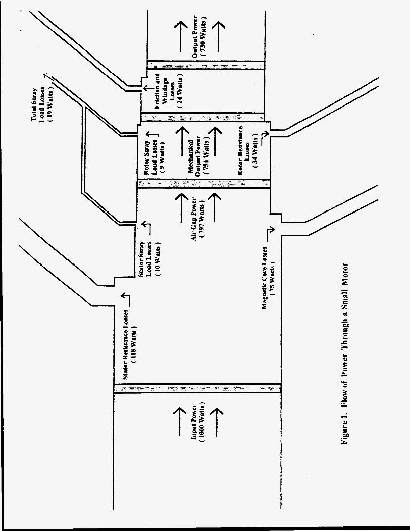
Figure 1 depicts the flow of energy through a typical small motor from input, across the boundaries of the motor, and out to useful mechanical power and to various losses. The flows are scaled to depict the typical sizes of the various flows in a motor with 1,000 watts input power. The actual loss distribution in any given motor can vary greatly from these typical values.

Discussion of Methods by Category
Segregated Loss Methods
The segregated loss methods are the most straightforward of the efficiency testing methods because they simply estimate the magnitudes of each motor power loss component. The individual loss components are then summed and subtracted from the power in to find the estimated power out. Some of the methods are quite complicated and intrusive, while others rely on empirical factors to estimate the losses.
IEEE Standard 112-1991, Method El
Except in extraordinary circumstances, method E is not a useful field test for efficiency. Its additional removed-rotor and reverse-rotation tests used to directly measure the fundamental frequency and high frequency stray load losses are too invasive and user unfriendly. Therefore, attention will be restricted to method E l . Even a literal interpretation of Method El would be impractical for field use, but the method is included here for completeness. Method El , in its IEEE 1 12 format, as discussed here, is probably seldom used in the field because it requires a variable load and a variable voltage power supply -
1. 2,
Method El specifies a comprehensive no load test. Method E l requires test under load at six equally spaced load points with four between 25 percent and 100 percent of full load and two greater than 100 percent and less than 150 percent. Method El specifies an assumed value for stray load losses at rated load. The repeatability of Method El is improved by requiring the adjustment of all resistance and slip measurements to a specified temperature.
3. 4.
Method El requires variable load tests, so the motor being tested must be connected to a variable load. Furthermore, during the no-load test the motor must be disconnected from its load and connected to a source of variable voltage. In most circumstances in the field this would be quite disruptive to normal operation of the system to which the motor is connected. Once the voltage, current, power and RPM data has been collected, the algorithms provided in IEEE 112 are used to calculate the individual component losses.
Ontario Hydro’s Simplified Segregated Loss Method
Ontario Hydro (1) proposes a segregated loss method that simplifies Method El much further. As pointed out in this study, it is not always possible to interrupt a process long enough to decouple a motor from its load and conduct a no load test. The study suggests that one way around this obstacle is to assume a value for the combined windage, friction and core losses. The study recommends that these combined losses be set to 3.5 percent of input rated power. The stray load losses are estimated based on the IEEE 112 standard assumed values.
This method can be simplified even further by using assumed values for rated power factor. Approximations can also be made for the temperature rise of the winding, and even the winding resistance could be estimated using a reading taken from the circuit breaker and subtracting the estimated cable resistance. The only other measurements required are power in to the motor and motor speed. The authors have experimented with a modified version of the Ontario Hydro method and found it to provide an accuracy of plus or minus 3 or 4 percentage points.

Commercial Devices
Commercial devices are available for measuring the efficiency of installed motors based on a modified version of the IEEE Standard 112, Method E l . These also require a measurement of power in, winding resistance, and speed.
Equivalent Circuit Met hods
The performance of an electric motor, at least with regard to efficiency, can be calculated from its equivalent electric circuit. These methods permit one to compute estimates of the efficiency of the motor when it is operating at loads other than those at which measurements were made.
IEEE Standard 1 12-1991 Equivalent Circuit Methods
The usual equivalent electric circuit of an induction motor is shown in the IEEE Standard 112-1991 (2), Method F.
Except in extraordinary circumstances, the IEEE Standard 112 Method F is not a useful field test for efficiency. As is true for Method E, its additional removed-rotor and reverse- rotation tests to directly measure the fundamental frequency and high frequency stray load losses are too invasive and user unfriendly. Therefore, we will restrict our attention to Method F 1.
The basic Method F1 requires an impedance test and the complete no load, variable voltage test. The version of Method F1 believed more suited to field use requires volts, watts, amperes, slip, stator winding temperature, or stator winding resistance to be measured at two values of voltage while operating at no load. In one case, measurements are made at rated voltage while operating at no load. In the other case measurements are made while operating at no load with voltage reduced until slip is equal to that obtained at the normal operating load. Once these measurements are made, an iterative procedure is used to determine the parameters of the equivalent circuit. The iterative procedure requires one to either know the design value of the ratio X 1 K 2 or to use the standard NEMA design value. Although this method is expected to be quite accurate, it is still considered to be too intrusive for routine field use.
Ontario Hydro’s Simplified Method F1
A modified version of the IEEE Standard Method F1 (2) is outlined in the Ontario Hydro Study (1).
A no load test and a full load test, both at rated voltage must be run. In turn, this requires one to disconnect the motor being tested from its load. Line voltage, input power, line current, power factor, and stator resistance at load temperature are measured after operating at no load and at full load, i.e. the normal operating load of the motor. The slip is also measured at full load.
This method eliminates the need for a variable voltage as required by IEEE Standard 112, Method F1 (2 ) .
The equivalent circuit used by this method is slightly different from that of Method F1. In this version of the equivalent circuit the impedance elements of the magnetizing branch are

shown in series while that of Method F1 is shown in parallel. This simplifies the no load version of the equivalent circuit as shown in (1).
Development of Equivalent Circuit from Nameplate Information
The least intrusive method to estimate efficiency is based on the use of an equivalent circuit derived from the motor’s nameplate data. Once the equivalent circuit of a motor is known, its running efficiency at any load can be determined simply by measurement of the motor speed.
The nameplate data provides information about the motor’s rated performance, locked rotor current, and design type. We have developed a set of algorithms that find the equivalent circuit from this data plus the value of the stator resistance. If the stator resistance is not known, it can also be estimated from motor nameplate data. The algorithms incorporate refinements to the basic equivalent circuit to account for the skin factor effects on the rotor and to treat stray load and friction and windage losses explicitly.
The accuracy of this method is of course closely related to the accuracy of the data in the nameplate. When the skin effects and explicit losses refinements are used, the efficiency estimates are also affected by the accuracy of the selected factors. Even with typical nameplate information of older conventional motors and rewound motors, this method has been shown in limited testing to provide an average accuracy of less than 3.5 percentage points.
Two Rotor Loops Equivalent Circuit Methods
The next two methods are based on an equivalent circuit that differs from the standard equivalent circuit. The revised equivalent circuit adds a second rotor loop.
Locked Rotor Method
A. Dell’ Aquila, L. Salvator, and M. Savino (3) present a procedure that uses two locked rotor tests to determine the parameters of an equivalent circuit with two rotor loops. An alternative procedure is to use a single locked rotor in conjunction with a load test to determine these parameters. In both cases a no load test must also be run. With these parameters in hand they then develop a method for computing the efficiency of the motor from the equivalent circuit relationships.
The advantages of this two rotor loop method are:
1.
2.
The procedure for determining parameters of equivalent circuit is not iterative like that of Method F1. According to the authors, the two reactance loop equivalent circuit represents double-cage and deep-bar rotor motor better than the single rotor loop equivalent circuits.
This method has two principal disadvantages:
1.
2 .
It requires a complete no load test with the motor to be connected to a variable voltage power source. It requires connecting the motor to a variable frequency source. This is too massive and user unfriendly for a good field test.

Standstill Frequency Response
A study (4) sponsored by the Electric Power Research Institute (EPRI) investigated the sensibility of determining the electrical equivalent circuit parameters of induction motors by using the standstill frequency response (SSFR) test. The approach investigated by the EPRI study was to measure the impedance of a motor, with its rotor stationary, over a frequency range of 0.01 to 500 Hz. The parameters of the equivalent circuit are then derived from these data.
The major advantage of this method over the standard method F1 is that the low voltage, no load test is not required. The level of applied voltage is much lower than that of the low voltage, no load test.
If a packaged test device with a variable frequency source is developed and made commercial-available, then the only drawback would be the no load test to determine friction and windage.
Slip Methods
SlipMethod
There are several versions of this method. All rely on a measurement of motor speed to find the slip. The measured slip (per unit) is the synchronous speed minus the measured speed divided by the synchronous speed. The rated slip is the synchronous speed minus the rated nameplate speed divided by the synchronous speed. The simplest version of the method is to find the ratio of the measured slip to rated slip and set this equal to efficiency. The obvious error is that the slip ratio represents the percentage of load and the efficiency is not equal to the percentage of load. Alternatively, one can also measure the power into the motor, and approximate the power out of the motor by multiplying the rated horsepower of the motor by the ratio of the measured slip to rated slip. The operating efficiency of the motor is thus approximated using the following relationship:
Efficiency = [Measured SliuRated Sliu) x Rated OutDut Power Input Power
Some users of this method try to enhance its accuracy by correcting the rated nameplate speed for voltage variations. This is done by taking the square of the ratio of the actual voltage to nameplate voltage and multiplying this time the rated speed. This is really only an exercise in good intentions, however, because the nameplate speed can be so inaccurate. The nameplate speed is allowed to deviate as much as 20% from the actual rated speed by NE,MA MG1 (9).
The main attraction of the standard slip method is its simplicity. However, several authors, e.g. ( 2 ) , (6), (7), and (l), have observed that the accuracy of the method suffers badly from several causes. Nailen (7) and the Arizona Department of Commerce Energy Office ( 5 ) provide an excellent discussion of the drawbacks of the slip methods, particularly the standard slip method. The scale of these inaccuracies is supported by the Arizona Department of Commerce Energy Office ( 2 ) which found that the slip method can differ from dynamometer results by over 40 percent.
Current Method
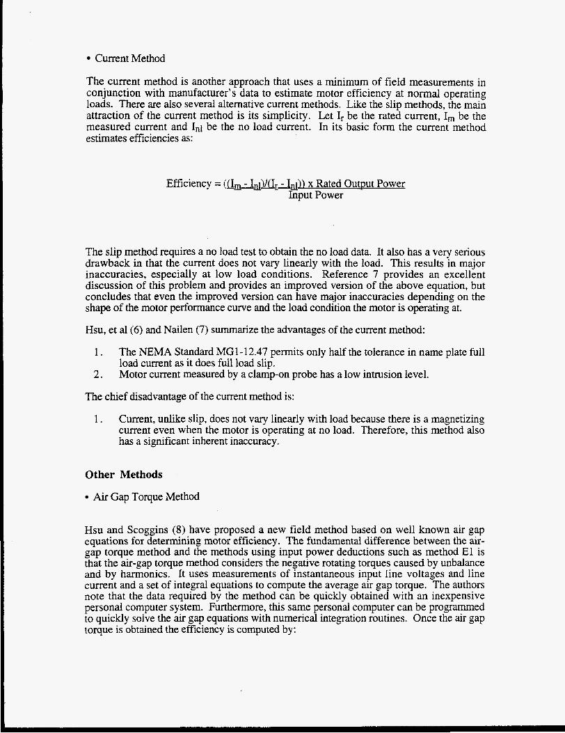
The current method is another approach that uses a minimum of field measurements in conjunction with manufacturer’s data to estimate motor efficiency at normal operating loads. There are also several alternative current methods. Like the slip methods, the main attraction of the current method is its simplicity. Let Ir be the rated current, Im be the measured current and In1 be the no load current. In its basic form the current method estimates efficiencies as:
Efficiency = (&, - - - - I,,l)/& - In1)) x Rated Outnut Power %put Power
The slip method requires a no load test to obtain the no load data. It also has a very serious drawback in that the current does not vary linearly with the load. This results in major inaccuracies, especially at low load conditions. Reference 7 provides an excellent discussion of this problem and provides an improved version of the above equation, but concludes that even the improved version can have major inaccuracies depending on the shape of the motor performance curve and the load condition the motor is operating at.
Hsu, et al(6) and Nailen (7) summarize the advantages of the current method:
1 .
2.
The NEMA Standard MG1-12.47 permits only half the tolerance in name plate full load current as it does full load slip. Motor current measured by a clamp-on probe has a low intrusion level.
The chief disadvantage of the current method is:
1 . Current, unlike slip, does not vary linearly with load because there is a magnetizing current even when the motor is operating at no load. Therefore, this method also has a significant inherent inaccuracy.
Other Methods
Air Gap Torque Method
Hsu and Scoggins (8) have proposed a new field method based on well known air gap equations for determining motor efficiency. The fundamental difference between the air- gap torque method and the methods using input power deductions such as method El is that the air-gap torque method considers the negative rotating torques caused by unbalance and by harmonics. It uses measurements of instantaneous input line voltages and line current and a set of integral equations to compute the average air gap torque. The authors note that the data required by the method can be quickly obtained with an inexpensive personal computer system. Furthermore, this same personal computer can be programmed to quickly solve the air gap equations with numerical integration routines. Once the air gap torque is obtained the efficiency is computed by:

(Air gap torque) 2 w - Wr+, - W,,, - Stray load losses
p, Eficiency =
The advantages of the method
1. 2 .
3.
Air gap torque can be measured while the motor is running. The air gap torque method should continue to provide optimum accuracy when the phase powers are unbalanced. This method can be used for non-induction motors such as the adjustable speed, brushless dc motors.
The major disadvantages of the method are:
1. 2.
3.
Current and voltage waveforms are required as input data. The core, friction and windage, and stray load losses must be estimated or measured. Software will be required to analyze the field measurements.
In general, higher confidence levels are provided by the more intrusive methods. In most cases, the user is not trying to make an exact determination of efficiency, but only a reasonable efficiency estimate for the motor replacement decision making process. Thus a high confidence level estimate may not always be required.
The major shortcoming of all the inservice methods is that they are based, to varying levels, on approximations of the motor performance based on design information. Degradation in the motor, or losses to due improper rewinds, may well not be detected.
In addition to estimating the motor's load and operating efficiency, a significant advantage of making a field measurement is that the user will obtain data about the motors actual service condition, and conditions such as voltage phase unbalance, over or under voltage, or excessive harmonic distortion can be assessed and then properly addressed. A properly applied motor will in general be more efficient and more reliable.
Significant testing has not been performed with the methods, but the authors would venture their opinions on three of the methods and their potential accuracies as follows:
1.
2.
3.
The most accurate method is probably the air gap torque method. This method, if used with a long enough sample time to average out any short term oscillations in the load (one second of sampling) should provide an accuracy of perhaps f 2 percentage points or better.
The second method is the modified Method El . If an accurate measurement of motor resistance, power in, and rpm can be made, this method should provide an accuracy of k 3.5 percentage points. This could be improved, especially at low load conditions, if a no load test can be made.
The third method is development of the equivalent circuit based on nameplate data. The significance of this method is that it has an extremely low intrusion level. Only

the nameplate data and a measure of RPM are required. We would estimate this method to have an accuracy of If: 4 percentage points.
References:
1.
2.
3.
4.
5 .
6.
7 .
a .
9.
Ontario Hydro, “In-Plant Electric Motor Loading and Efficiency Techniques”
IEEE Power Engineering Society, IEEE Standard Test Procedure for Polyphase Induction Motors and Generators, IEEE Std. 112-1991, December 5 , 1991.
Antonio Dell’ Aquila, “A New Test Method for Determination of Induction Motor Efficiency,” Technical Papers - IEEE Power Engineering Society 1984 Winter Meeting.
Electric Power Research Institute, “Derivation of Induction Motor Models from Standstill Frequency Response Tests,” GS-6250, July 199 1.
Arizona Department of Commerce Energy Office, “Energy Efficient Motors for HVAC Applications,’’ April 4, 1994.
John S. Hsu, “Selection of Efficiency Field Test Methods for Induction Motors,” working paper.
R. L. Nailen, “Finding True Power Output Isn’t Easy,” Electrical Apparatus, February 1994.
John S. Hsu, “Field Test of Motor Efficiency and Load Changes through Air-Gap Torque,” Paper presented and distributed in the DOE’S Tool and Protocol Workshop of Motor Challenge Program, September 22-23, 1994, Chicago, IL; accepted for publication, IEEERES Winter Meeting, January 27-February 2, 1995, New York, NY.
National Electrical Manufacturer’s Association (NEMA), NEMA Standards Publication Number MG1, 1993.
Biographies :
John D. Kueck holds a BS degree in Physics from Purdue University and an MS in Electrical Engineering - Power Systems from Ohio State University where he was an Ohio Electric Utility Institute Fellow. He has authored a number of publications on the subjects of electrical component reliability in Nuclear Generating Stations. Mr. Kueck was employed by both Sargent and Lundy Engineers and Combustion Engineering for five years and the Carolina Power and Light Company for ten years. He is presently a development engineer with the Oak Ridge National Laboratory.
Pedro J. Otaduy obtained the degree of “Ingeniero Superior en Tecnicas Energeticas“ at the University of the Basque Country (UBC), and the M.S.and Ph.D. in Nuclear Engineering at the University of Florida (UF). He joined the Oak Ridge National Laboratory (ORNL) in 1980 as an E. P. Wigner Fellow. He has contributed significantly in many areas involving mathematical simulation of engineering processes. Activities in the areas of Boiling Water Reactor Stability, Intelligent Supervisory Control andwavelets are dormant. He is presently involved in the simulation and diagnostics of electric motor performance in normal and

.
degraded conditions. He has authored over 34 publications and has lectured at ORNL,UBC, the University of Tennessee, and professional conferences.
John S. Hsu (Htsui) was born in China. He received a B.S. degree from Tsing-Hua University, Beijing, China, and a Ph.D. degree from Bristol University, England. He joined the Electrical and Electronics Engineering Department of Bradford University, England, serving there for nearly two years. After his arrival in the United States, he worked in research and development areas for Emerson Electric Company and later for Westinghouse Electric Corporation. He established the techcal innovations for the Westinghouse World Series motors. Many of his design programs are currently used by industry. Dr. Hsu served as head of the Rotating Machines and Power Electronics Program, Center for Energy Studies, the University of Texas at Austin for over four years. Presently, he is a senior staff scientist of the Digital and Power Electronics Group, Oak Ridge National Laboratory. He is the author or coauthor of many tecbcal publications and the inventor or eo-inventor of seven patents.