Embed Size (px)
Citation preview
EVALUATION OF BORD AND PILLAR MINING
SYSTEM IN MCL COAL MINES
A THESIS SUBMITTED IN PARTIAL FULFILLMENT OF THE
REQUIREMENTS FOR THE DEGREE OF
Bachelor of Technology
In
Mining Engineering
By
RAM CHANDRA NAYAK
10605015
& SANGRAM KESHARI DALAI
10605027
Department of Mining Engineering
National Institute of Technology
Rourkela-769008
2010
EVALUATION OF BORD AND PILLAR MINING
SYSTEM IN MCL COAL MINES
A THESIS SUBMITTED IN PARTIAL FULFILLMENT OF THE
REQUIREMENTS FOR THE DEGREE OF
Bachelor of Technology
In
Mining Engineering
By
RAM CHANDRA NAYAK
&
SANGRAM KESHARI DALAI
Under the Guidance of
Dr. MANOJ KUMAR MISHRA
Department of Mining Engineering
National Institute of Technology
Rourkela-769008
2010
National Institute of Technology
Rourkela
CERTIFICATE
This is to certify that the thesis entitled “EVALUATION OF BORD AND PILLAR MINING
SYSTEM IN MCL COAL MINES” submitted by Sri Ram chandra Nayak, Roll No. 10605015 &
Sri Sangram keshari Dalai, Roll No. 10605027 in partial fulfillment of the requirements for the
award of Bachelor of Technology degree in Mining Engineering at the National Institute of
Technology, Rourkela (Deemed University) is an authentic work carried out by them under my
supervision and guidance.
To the best of my knowledge, the matter embodied in the thesis has not been submitted to any
other University/Institute for the award of any Degree or Diploma
Date (Dr. MANOJ KUMAR MISHRA)
Associate Professor
Department of Mining Engineering
NIT Rourkela
ACKNOWLEDGEMENT
Our heart pulsates with the thrill for tendering gratitude to those persons who helped us in
completion of the project.
The most pleasant point of presenting a thesis is the opportunity to thank those who have
contributed to it. Unfortunately, the list of expressions of thank no matter how extensive is
always incomplete and inadequate. Indeed this page of acknowledgment shall never be able to
touch the horizon of generosity of those who tendered their help to us.
First and foremost, we would like to express our gratitude and indebtedness to Dr. Manoj Kumar
Mishra, for his kindness in allowing us for introducing the present topic and for his inspiring
guidance, constructive criticism and valuable suggestion throughout this project work. We are
sincerely thankful to him for his able guidance and pain taking effort in improving our
understanding of this project.
We are also grateful to Prof. S Jayanthu (Head of the Department) for assigning us this
interesting project and for his valuable suggestions and encouragements at various stages of the
work. An assemblage of this nature could never have been attempted without reference to and
inspiration from the works of others whose details are mentioned in reference section. We
acknowledge our indebtedness to all of them.
Last but not least, our sincere thanks to all my friends who have patiently extended all sorts of
help for accomplishing this undertaking.
DATE: Ram Chandra Nayak
PLACE: Sangram keshari Dalai
Dept. of Mining Engineering
National Institute of Technology
Rourkela – 769008
SYNOPSIS
Mining is the extraction of valuable minerals or other geological materials from the
earth, usually from an ore body, vein or (coal) seam. Any material that cannot be
grown through agricultural processes or created artificially is generally mined.
The chronological development of mining technology bears an important relation
to the history of civilization. In fact, as one of the earliest of human enterprises,
mining and its development correlate closely with cultural progress. Mining
processes involve prospecting for ore bodies, analysis of the profit potential of a
proposed mine, extraction of the desired materials. One of such methods is the
Bord and Pillar method of mining. Bord and Pillar method of mining is one of the
oldest methods of mining. The success of Bord and Pillar mining is selecting the
optimum pillar size. If the pillars are too large, then the extraction ratio decrease
leading to less production and profitability and if the pillars are too small it
becomes venerable to human safety. The issues relating to the stability of pillars
and effective extraction from it is a major concern now-a-days. Uniaxial
compressive strength reflects the true strength of a coal pillar. Tensile strength,
Tri-axial strength are other confirmatory tests for the Uniaxial compressive
strength. Safety factor is an important parameter for the design of pillars. Many
methods for calculating safety factor have been developed. Some of the significant
methods are Obert-Duvall and Bieniawski methods. For Indian coal mines, CMRI
has developed a formula for calculating the safety factor. Generally for Indian
mines, the proposed safety factor is 1.5-1.8. A correlation between safety factor
and excavation ratio and its application will boost the production and profitability
of any mine

CONTENTS
1. ABSTRACT……………………………………………………………………………….01
2. LIST OF FIGURES………………………………………………………………………..02
3. LIST OF TABLES…………………………………………………………………………03
4. CHAPTER: 01 INTRODUCTION………………………………………………………...04
1.1 AIM OF STUDY………………………………………………………………....06
1.2 METHODOLOGY……………………………………………………………….06
1.3 LAYOUT………………………………………………………………………....07
5. CHAPTER: 02 LITERATURE REVIEW………………………………………………….08
2.1 BACKGROUND INFORMATION………………………………………………09
2.2 DESIGN OF BORD AND PILLAR WORKINGS……………………………….16
2.3 BASIC PRINCIPLES OF PILLAR DESIGN…………………………………….19
2.4 EXTRACTION OF PILLARS……………………………………………………22
2.5 LABORATORY TECHNIQUES…………………………………………………28
6. CHAPTER: 03 MATERIALS AND METHODS………………………………………….38
3.1 DATA COLLECTION…………………………………………………………....39
3.2 DATA ANALYSIS……………………………………………………………….42
7. CHAPTER: 04 TEST RESULTS & DISCUSSIONS……………………………………...44
4.1 SLAKE DURABILITY TEST RESULT…………………………………………45
4.2 PROTODYAKONOV TEST RESULT…………………………………………..46
4.3 COMPRESSIVE STRENGTH TEST RESULT............................................….....46
4.4 TENSILE STRENGTH TEST RESULT………………………………………….47
4.5 TRIAXIAL TEST RESULT………………………………………………………47
8. CHAPTER: 05 CONCLUSION…………………………………………………………….51
5.1 CONCLUSION……………………………………………………………………52
5.2 FUTURE RECOMMENDATIONS……………………………………………….52
9. REFERENCES……………………………………………………………………………...53
1
ABSTRACT
The importance of mining is definitely significant to human civilization. In fact, as one of the
earliest of human enterprises, mining and its development correlate closely with cultural progress
Mining is the mother industry for other industries. For effectiveness in mining, different methods
have been approached keeping in mind the production and safety. One of such methods is the
Bord and Pillar method of mining. Bord and Pillar method of mining is one of the oldest
methods. The key to the successful Bord and Pillar mining is selecting the optimum pillar size.
If the pillars are too small the mine will collapse. If the pillars are too large then significant
quantities of valuable material will be left behind reducing the profitability of the mine. The
issues relating to the stability of pillars and effective extraction from it is a major concern now-a-
days. The most important parameter before designing a pillar is the Safety factor. The main
purpose of this project is to increase the extraction ratio of Bord and Pillar workings without
compromising the safety factor

2
LIST OF FIGURES
SL NO Name of figures Page no.
1 Cross section of typical Bord and pillar layout 11
2 Type of machineries in pillar mining 12
3 The tributary area pillar loading concept 19
4 The pressure arch theory 21
5 Multiseam working exploiting the intra-dosal region of pressure arch 21
6 Methods of pillar extraction 26
7 Steep diagonal line of extraction 26
8 Straight line of extraction 27
9 Slake durability test apparatus 30
10 Protodyakonov test set up 33
11 Uniaxial compressive test 34
12 Tensile test set up 35
13 Typical tri-axial test apparatus 36
14 Geographical map of Bundia mine 36
15 Borehole data 42
16 Tri-axial test graph 48
3
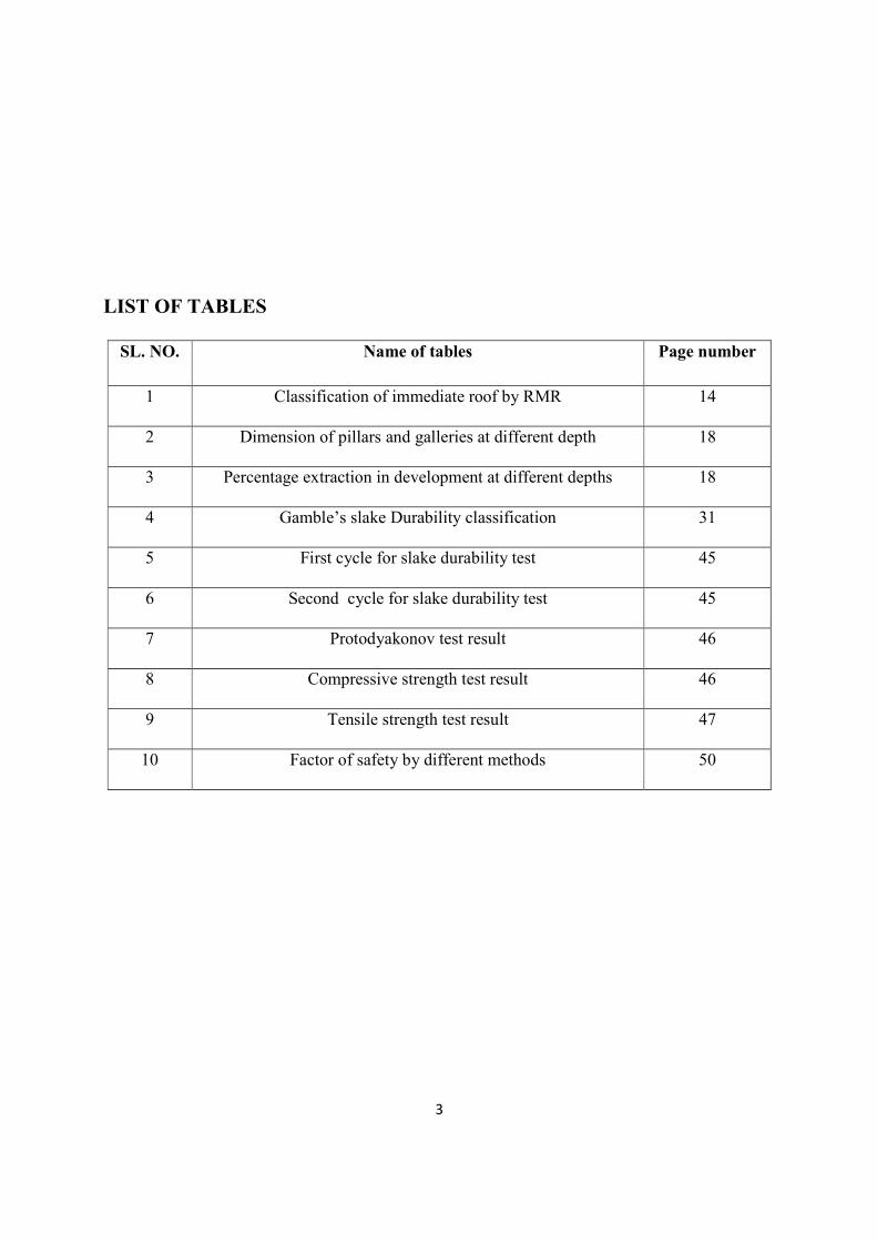
LIST OF TABLES
SL. NO. Name of tables Page number
1 Classification of immediate roof by RMR 14
2 Dimension of pillars and galleries at different depth 18
3 Percentage extraction in development at different depths 18
4 Gamble’s slake Durability classification 31
5 First cycle for slake durability test 45
6 Second cycle for slake durability test 45
7 Protodyakonov test result 46
8 Compressive strength test result 46
9 Tensile strength test result 47
10 Factor of safety by different methods 50
4
CHAPTER: 01
INTRODUCTION
Aim of the Study
Methodology
Layout
5
1.0 INTRODUCTION
The contribution of mining has played a big part in the development of civilization, more than is
usually recognized by the average citizen. In fact, products of the mineral industry pervade the
lives of all members of our industrialized society. The chronological development of mining
technology bears an important relation to the history of civilization. In fact, as one of the earliest
of human enterprises, mining and its development correlate closely with cultural progress. It is
no coincidence that the cultural ages of people are associated with minerals or their derivatives
(i.e., Bronze Age). Today, products of the mineral industry pervade the lives of all people.
Mining is the extraction of valuable minerals or other geological materials from the earth,
usually from an ore body, vein or (coal) seam. Any material that cannot be grown
through agricultural processes, or created artificially in a laboratory or factory, is usually mined.
Mining in a wider sense comprises extraction of any non-renewable resource (e.g.
petroleum, natural gas, or even water). Modern mining processes involve prospecting for ore
bodies, analysis of the profit potential of a proposed mine, extraction of the desired materials and
finally reclamation of the land to prepare it for other uses once the mine is closed. Coal seams
can be mined both by underground methods and opencast methods depending upon certain
conditions such as thickness and depth of the seam, dip of the seam, the ratio of overburden to
coal (stripping ratio) etc
The growing needs have been pushing the limits, to which the mining industry has to reach to lift
itself to fulfill the demand. The effect can be seen from the methods of mining that have evolved
over the years. One of the oldest methods of mining is the Bord and Pillar. It is a method in
which the mined material is extracted across a horizontal plane while leaving "pillars" of
untouched material to support the overburden leaving open areas or "rooms" underground. It is
usually used for relatively flat-lying deposits, such as those that follow a particular stratum.
The key to the successful Bord and Pillar mining is selecting the optimum pillar size. If the
pillars are too small the mine will collapse. If the pillars are too large then significant quantities
of valuable material will be left behind reducing the profitability of the mine. The percentage of
6
material mined varies depending on many factors, including the material mined, height of the
pillar, and roof conditions.
So proper designing of a pillar is necessary for successful Bord and Pillar working. Many
methods are available for designing of pillars. The most important parameter before designing a
pillar is the Safety factor. The main purpose of this project is to increase the extraction ratio of
Bord and Pillar workings without compromising the safety factor
1.1 Aim of the study: The goal of the present investigation is evaluation of the extraction ratio
of the Bord and Pillar working. This is achieved by addressing the following specific objectives.
1.1.1 Specific Objectives:
The primary objective of this project is to:
� To review current pillar design practices in terms of pillar size, pillar shape, seam
thickness, depth of mining, etc
� To determine the safety factor as practiced elsewhere
� To investigate the same in relation to a particular mine
The above goal and specific objectives are achieved by adopting the methodology as outlined in
the next session
1.2 Methodology
The above objectives could only be reached if acted upon with a planned approach. The first
step towards a goal always starts with knowing everything about it. Thus we began with the
literature review. The books, journals, papers proved a rich source of knowledge in this regard
and were thoroughly studied and learned. Discussion with officials encouraged us further in our
work.
7
This was followed by mine visits & collection of data from the field. The geological data
collected were location of seam, depth of seam, seam thickness etc and the mining data collected
were borehole data, pillar dimensions etc. Failed and stable case histories were also studied.
Samples from the mines were collected, carefully packed and sent to the laboratory for analysis.
Different experimentation work was carried out and based on it factor of safety was calculated.
Based on the safety factor, extraction ratio was evaluated without compromising the safety factor
1.3 Layout
This project report is divided into five chapters. Chapter 1 gives the general introduction, goal
and objectives of the report. A critical review of the available literature has been done in chapter
2 followed by tests, analysis and discussions in chapter 3 and 4 respectively. Chapter 5
concludes the work with further scope.
8
CHAPTER: 02
LITERATURE REVIEW
Background information
Design of Bord and Pillar workings
Basic principles of pillar design
Extraction of pillars
Laboratory techniques

9
CHAPTER 2 LITERATURE REVIEW
2.1 BACKGROUND INFORMATION
2.1.1 Introduction
Coal seams can be mined both by underground methods and surface mining methods depending
on certain conditions like:
� Thickness of seam
� Dip of seam
� Depth of occurrence
� The ratio of overburden to coal(stripping ratio)
Combining the features of both Bord and Pillar methods and Longwall methods, there is another
method of mining coal seams which is known as the “Shortwall Method” of mining. It
incorporates the advantages and disadvantages of both Bord and Pillar methods and Longwall
methods. There are two basic methods of underground coal mining methods. They are i) Bord
and Pillar method ii) Longwall method. Although the basic principles remain the same, there
could be many variants of these two methods.
In the U.K, former USSR, France and other European countries longwall method of coal mining
is the main method of mining. In India, about 98% of underground output of coal is obtained by
Bord and Pillar method and barely about 2% by longwall methods. The other countries where
Bord and Pillar method predominates are Australia, The USA and South Africa.
However due to various advantages associated with longwall method, the present trend is to
adopt longwall method of mining even in those countries also where Bord and Pillar method
predominates
The development of mine by the method of working known as Bord and Pillar consists of driving
a series of narrow roads, separated by blocks of solid coal, parallel to one another, and
connecting them by another set of narrow parallel roadways driven nearly at right angles to the
first set. The stage of formation of a network of roadways is known as development or first
working. The coal pillars formed are extracted after the development of the mine leasehold and
this later stage of extracting coal from pillars is known as depillaring.
10
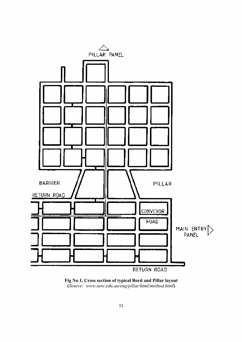
2.1.2 BORD AND PILLAR WORKING (Fig No 1)
This method is sometimes called room-and-pillar mining. It is commonly used for flat or gently
dipping bedded ores or coal seams. Pillars are left in place in a regular pattern while the rooms
are mined out. In many Bord and Pillar mines that are nearing closure, the pillars are taken out,
starting at the farthest point from the mine haulage exit, retreating, and letting the roof come
down upon the floor. Room-and pillar-methods are well adapted to mechanization
Before the advent of modern pillar design in 1967, or the adoption of special precautions when
mining at depths shallower than about 40 m, little was known about what size of pillars to leave
behind. Sometimes, in their eagerness to extract the maximum amount of coal, the old miners
left pillars too small to support the roof indefinitely. In addition, they sometimes ’robbed’ the
pillars on their retreat from the exhausted coal faces.
The Bord and Pillar method is adopted for working.
1. A seam thicker than 1.5 m,
2. A seam free from stone or dirt bands. Stone or dirt bands, if present in a seam, can be
easily disposed of for strip packing in long wall advancing method of mining.
3. Seams at moderate depth,
4. Seams which are not gassy,
5. Seams with strong roof and floor which can stand for long period after development stage
is over,
6. Coal of adequate crushing strength.
11
Fig No 1. Cross section of typical Bord and Pillar layout
(Source: www.uow.edu.au/eng/pillar/html/method.html)
12
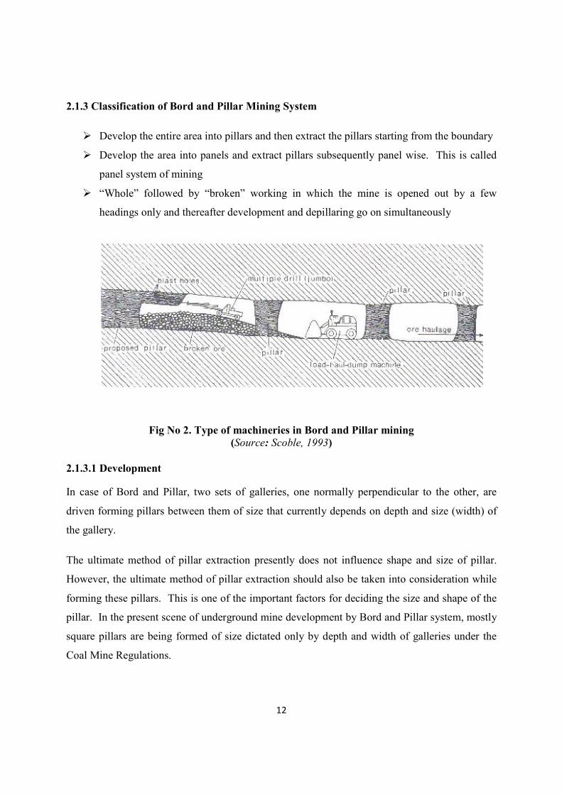
2.1.3 Classification of Bord and Pillar Mining System
� Develop the entire area into pillars and then extract the pillars starting from the boundary
� Develop the area into panels and extract pillars subsequently panel wise. This is called
panel system of mining
� “Whole” followed by “broken” working in which the mine is opened out by a few
headings only and thereafter development and depillaring go on simultaneously
Fig No 2. Type of machineries in Bord and Pillar mining
(Source: Scoble, 1993)
2.1.3.1 Development
In case of Bord and Pillar, two sets of galleries, one normally perpendicular to the other, are
driven forming pillars between them of size that currently depends on depth and size (width) of
the gallery.
The ultimate method of pillar extraction presently does not influence shape and size of pillar.
However, the ultimate method of pillar extraction should also be taken into consideration while
forming these pillars. This is one of the important factors for deciding the size and shape of the
pillar. In the present scene of underground mine development by Bord and Pillar system, mostly
square pillars are being formed of size dictated only by depth and width of galleries under the
Coal Mine Regulations.

13
A group of such pillars form what is known as a ‘panel’ and one panel is separated from another
panel by having solid coal barrier in between in the form of long rectangular pillars.
Connections between one panel and another should be as few as possible. Such connections
should be cut off by having permanent stoppings for complete isolation-of one panel with the
other as soon as utility of the few inter connections between the two panels is over. Size of panel
depends on many factors, two of which are the incubation period for the coal to be extracted and
its rate of extraction.
Normally, formation of pillars in a panel and pillar extraction is separate activities, one after the
other, and a long time may pass between the two. Thus, coal pillars may stand for years before
they are extracted. In fact, this has become one of the major problems of Indian coal mining
industry.
It is better to first develop a panel by a pair of galleries each on the rise and dip side of the panel
and interconnect these pairs at the panel boundary by a pair of dip-rise galleries. Thereafter, on
the retreat, pillars can be formed till just before extraction, the shape and size of the pillar will
suit the method of extraction and ventilation and transport during pillar formation and extraction
will be common, thus, very much facilitated. Further other advantages associated with
concentrated production will be available.
2.1.3.1.1 Support system during development
Considering that roof falls cause the largest number of mine accidents, it was decided a few
years ago to support a 9 m length of a gallery immediately out bye of the working face. These
supports may be temporary or permanent in nature. If temporary, they can be replaced by
permanent supports, if the roof conditions so dictate or can be taken out completely, if the roof
stratum is found to be self supporting. However, the current trend is to consider that practically
no strata is self- supporting for the size of development galleries normally driven. Now, mine
managements have to necessarily prepare support plans for the mine as a whole.
The above stipulation and the past experience have encouraged installation of roof bolts in Indian
Coal mines. Roof bolting as the sole system of support has been accepted by Directorate of
Mines Safety for mine development galleries. Roof bolting, now, is beginning to be accepted as
the sole system of support in depillaring areas and for certain geo-mining and operating

14
conditions. Conventional supports in depillaring areas can be reduced if roof bolts are also used.
Shiftable hydraulic roof bolting machines are being popular.
In order to determine the system of support to be followed, Rock Mass Rating (RMR) is
determined for the immediate roof, say, up to 2 m above gallery height. For this purpose,
generally, the following parameters are considered:
• Layer thickness,
• Structural features,
• Rock weathering ability
• Rock strength, and
• Ground water seepage.
By giving different values to the above parameters for possible maximum total of 100, a
combined rating for the immediate roof emerges. The weight ages to these parameters are 30,
25, 20, 15, and 10 respectively. An immediate roof is, thus, divided into the five categories.
Classification of immediate roof by Rock Mass Rating by the above method is given:
Table No 1. Classification of immediate roof by RMR
RMR so determined can be further adjusted for factors such as width of excavation (higher RMR
for lesser width and vice versa) and depth (lower RMR for depths beyond 250 m or so). From
RMR, rock load per sq m is calculated by using an empirical formula as follows:
Rock mass rating (RMR) Category of Roof
Less than 20 Very poor
20 to 40 Poor
40 to 60 Fair
60 to 80 Good
80 to 100 Very good

15
��������� �� � �� � ������ � ��������� � �����������
Where, W is width of gallery in meters and d is mean rock density
The support system can be designed giving a factor of safety of 1.5 to 2.0. Using the concept of
RMR, as a basic input data in designing support system, is of recent origin and norms are still
under evolution. It is a good practice to determine RMR for a few places in a mine, as it may
vary from place to place. Life of roadways should also be considered while designing the
system. The final method of pillar extraction should also be considered. The system should be
such that does not get disturbed during and is merely reinforced, if needed.
In order to keep support cost low, it is essential that the percentage of coal extraction during
pillar formation should not be high. It is suggested that, even for shallow depths, this percentage
should be within 30. More coal in pillars will indirectly benefit depillaring operations also. For
a given percentage of extraction, galleries should be as narrow as the proposed mechanization
will permit. Long rectangular pillars should be formed as the number of 4-way junctions
considerably reduces with rectangular pillars which will not require splitting before extraction.
2.1.3.2 Depillaring
After pillars have been formed on the Bord and Pillar system, consideration has to be given to
the extraction of coal pillars; the operation is known as pillar extraction. It is also referred to as
depillaring. In a method of depillaring, known as the caving method, the coal of pillars is
extracted and the roof is allowed to break and collapse into the voids or the de coaled area,
known as goaf. As the roof strata about the coal seam break, the ground surface develops cracks
and subsides, the extent of damage depending upon depth, thickness of the seam extracted, the
nature of strata, thickness of the subsoil and effect of drag by faults.
Depillaring with stowing is a method of pillar extraction in which the goaf is completely packed
with incombustible material and generally plasticized where it is necessary to keep the surface
and strata above the seam intact after extraction of coal. The following circumstances would
require adoption of depillaring with stowing:
16
1. Presence of water bearing strata above the coal seam being extracted. Enormous
quantities of water beyond the economic pumping capacity may enter the mine through
cracks in the strata.
2. Railways, rivers, roads, etc. situated on the surface, which cannot be diverted.
3. Presence of fire in a seam above the seam to be extracted.
4. Existence of one or more seams of marketable quality extractable in the near future.
5. Restrictions imposed by local or Government authorities for the protection of the
surface.
6. Extraction of the full thickness of a seam thicker than 6 m, as thicker seams cannot be
extracted fully by caving method.
7. Extraction of seams very prone to spontaneous heating, of very gassy nature or liable to
pumps.
8. Surface buildings which cannot be evacuated.
9. Tanks, reservoirs, etc. which cannot be emptied.
2.2 Design of Bord and Pillar Workings
The main elements of Bord and Pillar workings are:
2.2.1 Size of the Panel
The main consideration in deciding the size of the panel is the incubation period of the coal
seam. The size is so fixed that the entire panel can be extracted within the incubation period
without the occurrence of spontaneous fire. The period in Indian coalfields generally varies
between 6 to 12 months. The other factors that influences the size is the rate at which extraction
is done. With high rates of extraction made possible by mechanization, the size of the panel can
be significantly increased. The extraction rate from depillaring districts in Indian coalfield
averages about 250-300 tons per day per panel
Sometimes panel sizes are determined by strata control considerations. For example, in “Yield
Pillar” technique the panel size is so fixed as to cause main abutment pressure to be carried by
barriers which are made of substantial width and the pillars in the panel are made smaller as to
‘yield’ and throw the limbs of the main pressure arch on barriers. This way percentage
extraction from a panel can be substantially decreased.
17
2.2.2 Size of the Barrier
The width of the barrier depends on the load which it has to carry and its strength. Greater the
depth of working, wider is the barrier and also softer the coal, the more, the width of the barrier.
In practice, the width of the barrier enclosing pillars in a panel is usually the same as is the width
of the coal pillars which are enclosed within the panel. In deep mines the width of the barrier
may become quite large (up to 45 m) and so during extraction they are thinned down consistent
with safety. Too much reduction in the width of the barrier is not advisable as in that case the
barrier may be crushed and two goaves may be joined, thus encouraging safety. For the
determination of “Yield Pillar” technique, it is necessary to take into consideration the load at the
abutments of the pressure arch and the strength of barrier pillars.
2.2.3 Size of Pillars
The size of the pillars is influenced by the following:
� Depth from the surface and percentage extraction in the first workings or development.
� Strength of the coal: Seams with weak coal require large pillars. Effect of atmosphere
and escape of gas also influence the size of pillars
� The nature of the roof and floor. These influence the liability to crush and creep. A
strong roof tends to crush the pillar edges whilst a soft floor predisposes it to creep and
both calls for large pillars.
� Geological Considerations: In the vicinity of faults, large pillars are required. Dip and
presence of water also influences the decision as to the size of pillars.
� Time dependant strain: With time the strain goes on increasing, the load remaining
constant and if the size of the pillar is not sufficiently large, then it may fail under the
time dependant strain, although initially it might be stable
Also, with the passage of time, weathering takes place which reduce the strength of coal pillars.
In India, the dimensions of pillars and the width and height of galleries are regulated by
Regulation 99 of Coal Mines Regulation 1957. It is stipulated that the width of galleries shall
not exceed 4.8 m and the height of the galleries shall not exceed 3 m. For width of galleries
ranging from 3 m to 4.8 m, the dimensions of pillars for various depths of working are given
below:
18
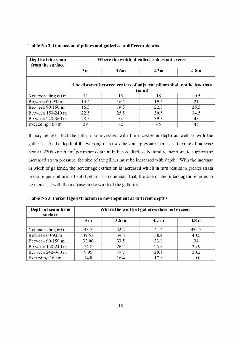
Table No 2. Dimension of pillars and galleries at different depths
Depth of the seam
from the surface
Where the width of galleries does not exceed
3m 3.6m 4.2m 4.8m
The distance between centers of adjacent pillars shall not be less than
(in m)
Not exceeding 60 m 12 15 18 19.5
Between 60-90 m 13.5 16.5 19.5 21
Between 90-150 m 16.5 19.5 22.5 25.5
Between 150-240 m 22.5 25.5 30.5 34.5
Between 240-360 m 28.5 34 39.5 45
Exceeding 360 m 39 42 45 45
It may be seen that the pillar size increases with the increase in depth as well as with the
galleries. As the depth of the working increases the strata pressure increases, the rate of increase
being 0.2306 kg per cm2 per meter depth in Indian coalfields. Naturally, therefore, to support the
increased strata pressure, the size of the pillars must be increased with depth. With the increase
in width of galleries, the percentage extraction is increased which in turn results in greater strata
pressure per unit area of solid pillar. To counteract that, the size of the pillars again requires to
be increased with the increase in the width of the galleries.
Table No 3. Percentage extraction in development at different depths
Depth of seam from
surface
Where the width of galleries does not exceed
3 m 3.6 m 4.2 m 4.8 m
Not exceeding 60 m 43.7 42.2 41.2 43.17
Between 60-90 m 39.53 39.8 38.4 40.5
Between 90-150 m 33.06 33.5 33.8 34
Between 150-240 m 24.8 26.2 25.6 25.9
Between 240-360 m 9.95 19.7 20.1 20.2
Exceeding 360 m 14.8 16.4 17.8 19.0

19
2.3 Basic Principles of Pillar design
Pillar loading is of three types, preliminary loading or loading immediately following excavation
of opening, subsequent loading or the abutment pressures due to further mining (i.e. when
massive extraction, such as longwall or pillaring, is happening near the pillar) and progressive
failure theory for post-mining loading.
Tributary Area Concept: According to this concept, a pillar takes the weight of overlying rock
up to a distance of half the opening width surrounding it. In the figure, �� and ��
are widths of
the opening and pillar respectively, while �� is the length of the pillar. For square pillars, ��
=���.
Fig No 3. The tributary area pillar loading concept
(Source: Bieniawski, Z. T., 1984)
The load on the pillar, P, is, therefore,
� !��� ������" �� ���� � ����# � $ � %
Where γg is the weight of the rock per unit volume, and h is the depth of the pillar. The stress on
the pillar σp is:
&' = P/Area of pillar = (���� � ���� � !��� � ���"�# � $ � %�)*(�� � ���)
= (���� � ���� � !��� � ���" �� �&+)*(�� � ���)
Where &+ is the vertical stress γgh. Another formula that works is

20
&�,���� � % � (���� � ���� � !��� � ���"*��� � ����)
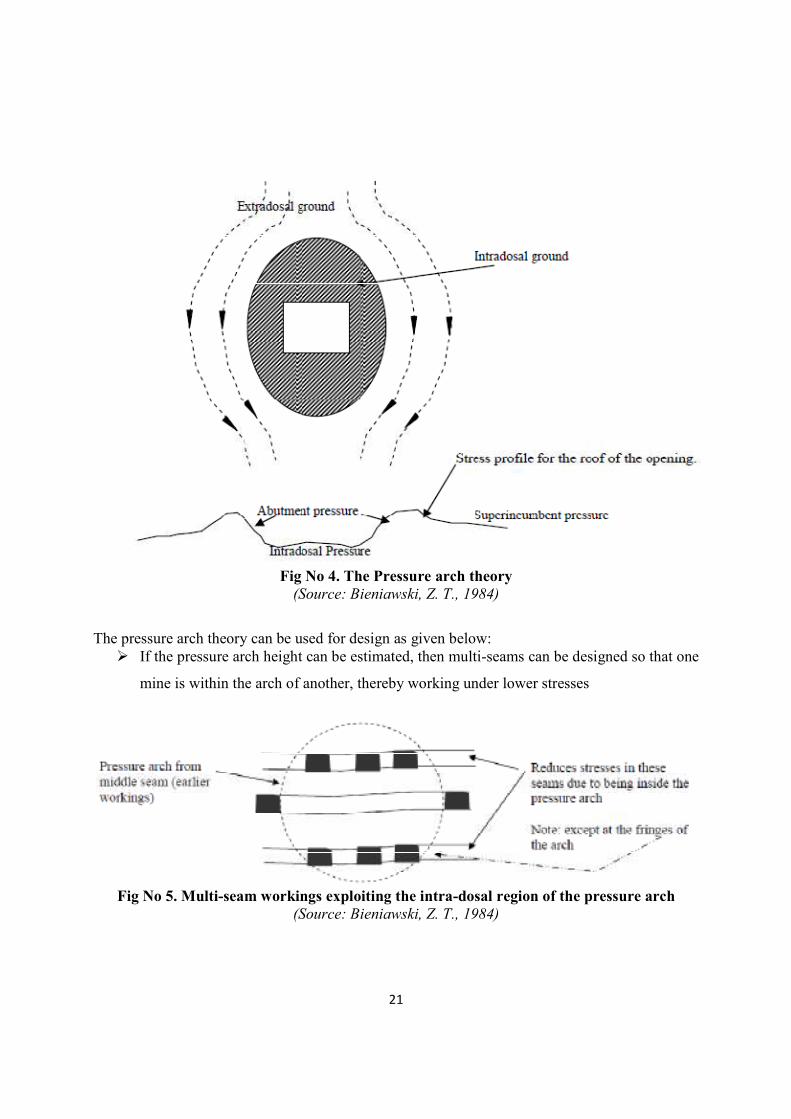
Pressure Arch Theory: According to this theory, when an opening is made, the stresses shift
outward on both sides of pillar, leaving a de-stressed zone, in the shape of an arch, around the
pillar. The exact shape and size of the arch depends on the stress levels, age and shape/size of
opening, and strata properties. Subsidence occurs when the arch reaches the surface.
The de-stressed area inside the arch is called intradosal ground, while the area outside is called
extradosal ground. The stratum at the fringe of the intradosal ground gets compressed as part of
the vertical stress is transferred to the abutments. The height of the intradosal ground is about 2-
4 times the width of the extraction. For large excavations, the height is limited to 200 times the
excavation height. Regions where pillars are being exploited can be thought of as large
excavations.
A disadvantage of this theory is that due to a lack of a quantitative estimate of the pressure arch
profile, it is difficult to design for (how would you estimate what the intradosal pressure on the
roof of an opening is if you do not know where the arch begins).
As mentioned earlier, an aspect of the pressure arch theory is subsidence. When an excavation
exceeds a certain width, the pressure arch can reach all the way to the surface causing
subsidence.
21
Fig No 4. The Pressure arch theory
(Source: Bieniawski, Z. T., 1984)
The pressure arch theory can be used for design as given below:
� If the pressure arch height can be estimated, then multi-seams can be designed so that one
mine is within the arch of another, thereby working under lower stresses
Fig No 5. Multi-seam workings exploiting the intra-dosal region of the pressure arch
(Source: Bieniawski, Z. T., 1984)
22
Yield pillar design: This concept aims to extend the benefits of the pressure arch theory to the
current mining activities rather than to future mining activities. Here, pillars in a panel are
designed to not take the full load. Instead, they are slightly under-designed. This obviously
causes the pillars to yield, thereby transferring their load to the barrier pillars or to larger pillars
in the same panel. Barrier pillars are large pillars that separate one panel from another. Yield
pillars are also advantageous for very deep mines. In deep mines, if pillars are designed to
support the full load, the pillar dimensions become very large (verify this by using the tributary
area method for pillar load and Bieniawski’s formula for pillar strength). Besides, pillar stresses
are high as well. On the other hand, if pillars are designed to yield, not only do the dimensions
remain reasonable, but the pillar stresses are reduced as well.
2.4 Extraction of Pillars
After the formation of pillar, their extraction is done from one end of the panel. If the
development was not done in panels, artificial panels of suitable sizes are created by building
stoppings around the pillars intended to be extracted such that the extraction of all the pillars of a
panel is completed within the incubation period as required under regulation 118 A of the Coal
Mine Regulation 1957. Further Regulation 100 of CMR 1957 lays down certain conditions
which must be complied with during the extraction. Some of the statutory requirements are given
below
“100 (1)No extraction or reduction of pillars shall be commenced, conducted or carried out
except with the permission in writing of the 1[Regional Inspector] and in accordance with such
conditions as he may specify therein. An application for permission under this sub-regulation
shall be accompanied by two copies of an up-to-date plan of the area where pillars are proposed
to be reduced or extracted showing the proposed extend of extraction or reduction of pillars, the
manner in which such extraction or reduction is to be carried out the thickness and depth of the
seam, the nature of the roof, and the rate and direction of dip.
“(2) The extraction or reduction of pillars shall be conducted in such a way as to prevent, as far
as possible the extension of a collapse or subsidence of the goaf over pillars which have not been
extracted.

23
“(3)(a) Save as provided by clause (b), no pillars shall be reduced or split in such a manner as to
reduce the dimensions of the resultant pillars below those required by regulation 99 or by any
order made there under, nor shall any gallery be so heightened as to exceed three meters.
“(b) During the extraction of pillars, no splitting or reduction of pillars or heightening of galleries
shall be affected for a distance greater than the length of two pillars ahead of the pillar that is
being extracted or reduced :
Provided that where pillar extraction is about to begin in a district such splitting or reduction of
pillars or the heightening of galleries shall be restricted to a maximum of four pillars. The width
of the split-galleries shall not exceed the width prescribed for galleries under regulation 99(4).
“(c) The Regional Inspector may, by an order in writing and stating the reasons therefore, relax
or restrict the provisions of this sub-regulation in respect of any specified workings to such
extend and on such conditions as he may specify therein.
“(4) Except where the voids formed as a result of extraction are stowed solid with sand or other
incombustible materials, no extraction of pillars in any seam or section shall be commenced until
the fire dams or stoppings have been provided on all openings, other than openings essential for
ventilation and haulage around the area to be extracted. And in the roads kept open for
ventilation and haulage, foundations for such dams or stoppings shall be prepared and bricks and
other suitable materials shall be kept readily available in their vicinity. Shale or other
carbonaceous material shall not be used in the construction of fire dams or stoppings.
“(5) Whether the method of extraction is to remove all the coal or as much of the coal as
practicable and to allow the roof to cave in, the operations shall be conducted in such a way as to
leave as small an area of un-collapsed roof as possible. Where possible, suitable means shall be
adopted to bring down the goaf at regular intervals
Further, as a precaution against spontaneous combustion in a seam prone to autogenous fire
additional precautions have been stipulated in Regulation 11 A which reads as below
118A. – Further precautions against spontaneous heating – The following further precautions
shall be taken against the danger of spontaneous heating:
(1)(a) The seam or section shall be worked in panels having independent ventilation in such a
manner that it is possible to isolate one from another easily if necessary. Where development
has already been made without regard to this factor, artificial panels should be created by the
construction of stoppings. In determining the size of the panel due consideration shall be given
24
to the desirability of enabling complete extraction of the pillars therein within the incubation
period of the coal.
(b) No coal, shale or other carbonaceous material shall be left or stacked belowground. Where
removal of fallen coal out of the mine is not practicable, the area shall be effectively sealed off.
(d) A panel is isolated by adequate stoppings as soon as it has been goaved out.
The essence of the regulations is
(i) To take effective steps for good roof control so as to prevent premature collapse and
overriding of pillars and to ensure regular caving of the roof; and
(ii) To take necessary steps against spontaneous heating so as to enable complete
extraction of coal without spontaneous combustion occurring and to be in readiness to
seal off the district is case spontaneous heating occurs.
2.4.1 Problems in the extraction of pillars
1. The operations of pillar extraction are beset with the problems of strata control. If the
operations have not been designed scientifically, there are the dangers of major strata
movement setting in, which may result in the overriding of pillars, and premature
collapse. In the past and also recent years in the Jharia coalfields and elsewhere during
extraction of pillars in thick seams, especially seams developed in multi-sections,
premature collapses have occurred involving large areas. Besides, in seams prone to
bumps like Dishergarh seam extraction of pillars has led to serve and frequent
occurrences of bumps and considerable quantities of coal has been lost. In some seams,
the roof does not cave in over large areas for quite some time and/when it does cave in,
air blasts occur resulting in accidents. In central India, air blasts of high intensity have
occurred in the pas causing fatalities to miners.
2. Maintenance of acceptable environment is not easy. Splitting of pillars provides many
leakage routes and heightening and widening of galleries increase cross-sectional areas
and hence the velocity of ventilating air is reduced. The ventilation in depillaring faces
often becomes sluggish. Airborne dust concentrations increase and climatic conditions
generally become uncomfortable.

25
3. Usually, some coal is left in the goaf, which may be 15-20% of the panel reserve. This
gets crushed, oxidation sets in and eventually fire may break out. There are numerous
cases of fire occurring in depillaring districts in Indian coal mines.
4. Mechanization of coal getting is not easily possible on account of difficulty of roof
control.
5. Because of reasons give at 1.2 and 4 above, the production from district is not high and
the output per man-shift is low.
2.4.2 Principles of Pillar extraction techniques
The principles of designing pillar extraction techniques are given below:
1. Roof exposure at one time should be minimal. In the Indian coalfields, where caving is
practiced, 60-90 m2 exposure is normally allowed. But in stowing districts the exposure
may be increases up to 90-100 m2.
2. The size of the panel should be such as depillaring can be completed within the
incubation period. This period commonly varies between 6-9 months. But there are
some seams in which fire has not occurred even thought depillaring has been going on for
more than two years and yet there are some seams in which spontaneous heating has been
reported within three to four months of the commencement of depillaring. In a lignite
mine spontaneous heating took place within a few weeks only.
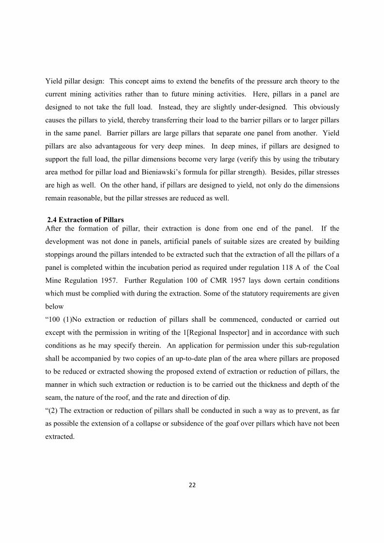
3. The extraction line should be so arranged as to facilitate roof control. In practice o
diagonal line, or step diagonal line of face is common. In special cases a steep diagonal
line of face or even straight line of face has been selected. Diagonal or step diagonal line
of face provides protection as the working places are supported by solid pillars and also
when the roof caves, there is less risk of goaf flushing into the working faces. It is also
claimed that diagonal line of extraction helps in the caving of the roof.
26
A) Diagonal line of extraction B) Step diagonal line of extraction
Fig No 6. Methods of Pillar extraction
(Source: R.D.Singh, 2005)
In the panel worked in conjunction with hydraulic sand stowing-diagonal line of face is
prepared as it facilitates water drainage without flooding the working faces in the lower
level.
4. The single lift extraction is limited to height of 4.8 m or less. If the thickness of the seam
is more than 4.8 m, the extraction is done in multi-lifts and in that case hydraulic sand
stowing is insisted upon. Seams up to 4.8 m thick can be mined by caving in one pass.
5. Whatever the method of extraction, the working area is systematically supported by cogs
and props.
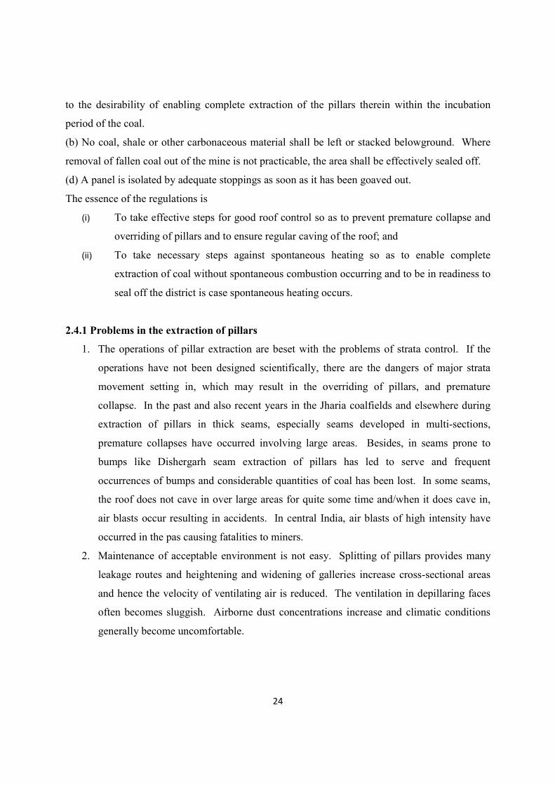
Fig No 7. Steep diagonal line of extraction
(Source: R.D.Singh, 2005)
27
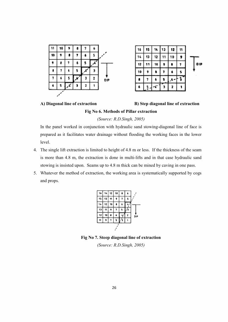
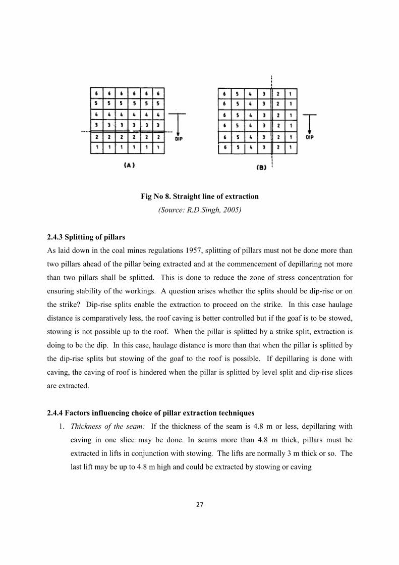
Fig No 8. Straight line of extraction
(Source: R.D.Singh, 2005)
2.4.3 Splitting of pillars
As laid down in the coal mines regulations 1957, splitting of pillars must not be done more than
two pillars ahead of the pillar being extracted and at the commencement of depillaring not more
than two pillars shall be splitted. This is done to reduce the zone of stress concentration for
ensuring stability of the workings. A question arises whether the splits should be dip-rise or on
the strike? Dip-rise splits enable the extraction to proceed on the strike. In this case haulage
distance is comparatively less, the roof caving is better controlled but if the goaf is to be stowed,
stowing is not possible up to the roof. When the pillar is splitted by a strike split, extraction is
doing to be the dip. In this case, haulage distance is more than that when the pillar is splitted by
the dip-rise splits but stowing of the goaf to the roof is possible. If depillaring is done with
caving, the caving of roof is hindered when the pillar is splitted by level split and dip-rise slices
are extracted.
2.4.4 Factors influencing choice of pillar extraction techniques
1. Thickness of the seam: If the thickness of the seam is 4.8 m or less, depillaring with
caving in one slice may be done. In seams more than 4.8 m thick, pillars must be
extracted in lifts in conjunction with stowing. The lifts are normally 3 m thick or so. The
last lift may be up to 4.8 m high and could be extracted by stowing or caving
28
2. Depth of the seam: At greater depths, the pillars must be larger and they are extracted in
conjunction with stowing. Splits have to be driven on strike.
3. Roof of the seam: For successful depillaring roof must be cave regularly. A roof with
compressive strength of less than 500 kg/ cm2 is normally a capable roof. Massive and
strong roofs create problems in caving and blasting may have to be restored to induce
caving.
4. Incubation period of the seam: Coal seam with longer incubation period may be
extracted in larger panels. To achieve the same effect, i.e. to make the panel larger,
mechanizations of operations are necessary in a seam with shorter incubation period so
that rate of extraction is increased.
5. Dip of the seam: In steeply inclined seams, special techniques of extraction have to be
designed such as Topping method.
2.5 LABORATORY TECHNIQUES
The testing of coal sample was conducted for measuring and evaluating the changes of rock
properties as well as its properties by applied loading or force. The properties will include
physical, index and strength whereby the behavior include deformation and failure mode. As
stated before, the two most common methods of laboratory testing for rock are:
1) Indirect Strength test;
2) Direct Strength test.
The types are generally based on the methods of testing and the nature or type of data obtained.
Indirect Strength Test
Index test is relatively simple and rapid to conduct, but it does not provide fundamental property.
The data obtained is just an indicator on property that being tested. The apparatus used are
normally simple and portable which also allows the test to be conduct at site.
The tests may not require some detailed sample preparation where certain tests are non-
destructive type and does not involve failure of samples (cost saving for sample could be reused).
29
The data also not suitable for detailed design purposes but it is useful and valuable for
preliminary or pre-feasibility assessments.
The tests for Indirect Strength test include:
• Slake durability index test
• Uni-axial compressive strength test
• Brazilian or Indirect tensile strength test
Direct Strength Test
The test procedure requires detailed preparation of sample in terms of standard shapes and
finishing. The sample preparation process is equipment related and it is costly. The testing itself
involving sophisticated and large equipment significant to the detailed testing procedures and
may require complex analysis and this is also costly.
However, the data obtained is the fundamental property and would be the direct presentation of
property being evaluated. The numbers of tests were limited due to its cost of operation and with
this the data obtained can be use for detailed design.
The tests for Direct Strength test include:
• Permeability of rock
• Modulus of deformation
• Uniaxial and Triaxial compressive strength test
TESTS CONDUCTED
1) Slake durability index
2) Protodyakonov test
3) Uniaxial compressive test
4) Tensile test
5) Triaxial test
30
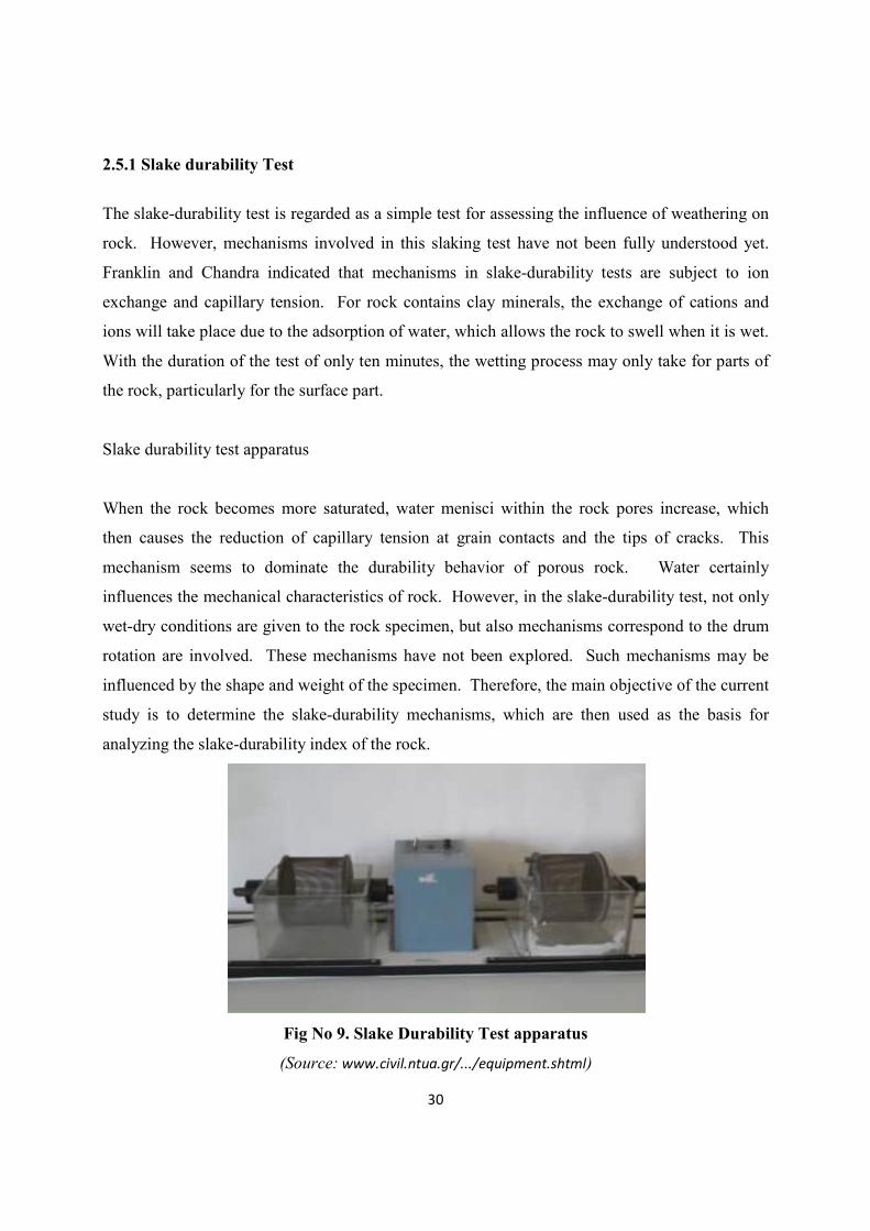
2.5.1 Slake durability Test
The slake-durability test is regarded as a simple test for assessing the influence of weathering on
rock. However, mechanisms involved in this slaking test have not been fully understood yet.
Franklin and Chandra indicated that mechanisms in slake-durability tests are subject to ion
exchange and capillary tension. For rock contains clay minerals, the exchange of cations and
ions will take place due to the adsorption of water, which allows the rock to swell when it is wet.
With the duration of the test of only ten minutes, the wetting process may only take for parts of
the rock, particularly for the surface part.
Slake durability test apparatus
When the rock becomes more saturated, water menisci within the rock pores increase, which
then causes the reduction of capillary tension at grain contacts and the tips of cracks. This
mechanism seems to dominate the durability behavior of porous rock. Water certainly
influences the mechanical characteristics of rock. However, in the slake-durability test, not only
wet-dry conditions are given to the rock specimen, but also mechanisms correspond to the drum
rotation are involved. These mechanisms have not been explored. Such mechanisms may be
influenced by the shape and weight of the specimen. Therefore, the main objective of the current
study is to determine the slake-durability mechanisms, which are then used as the basis for
analyzing the slake-durability index of the rock.
Fig No 9. Slake Durability Test apparatus
(Source: www.civil.ntua.gr/.../equipment.shtml)
31
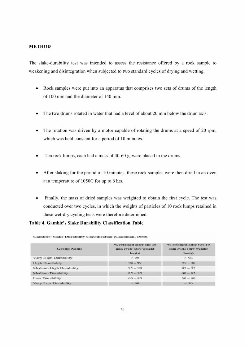
METHOD
The slake-durability test was intended to assess the resistance offered by a rock sample to
weakening and disintegration when subjected to two standard cycles of drying and wetting.
• Rock samples were put into an apparatus that comprises two sets of drums of the length
of 100 mm and the diameter of 140 mm.
• The two drums rotated in water that had a level of about 20 mm below the drum axis.
• The rotation was driven by a motor capable of rotating the drums at a speed of 20 rpm,
which was held constant for a period of 10 minutes.
• Ten rock lumps, each had a mass of 40-60 g, were placed in the drums.
• After slaking for the period of 10 minutes, these rock samples were then dried in an oven
at a temperature of 1050C for up to 6 hrs.
• Finally, the mass of dried samples was weighted to obtain the first cycle. The test was
conducted over two cycles, in which the weights of particles of 10 rock lumps retained in
these wet-dry cycling tests were therefore determined.
Table 4. Gamble’s Slake Durability Classification Table
32
METHOD OF CALCULATION
• Initial weight taken = A
• Weight after 1st cycle = B
• Weight after 2nd
cycle = C
• % retention after 1st cycle =(A-B)/A × 100
• % retention after 2nd cycle=(B-C)/B × 100
Compare in gamble’s table.
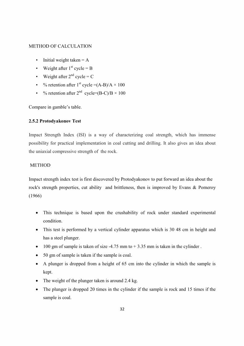
2.5.2 Protodyakonov Test
Impact Strength Index (ISI) is a way of characterizing coal strength, which has immense
possibility for practical implementation in coal cutting and drilling. It also gives an idea about
the uniaxial compressive strength of the rock.
METHOD
Impact strength index test is first discovered by Protodyakonov to put forward an idea about the
rock's strength properties, cut ability and brittleness, then is improved by Evans & Pomeroy
(1966)
• This technique is based upon the crushability of rock under standard experimental
condition.
• This test is performed by a vertical cylinder apparatus which is 30 48 cm in height and
has a steel plunger.
• 100 gm of sample is taken of size -4.75 mm to + 3.35 mm is taken in the cylinder .
• 50 gm of sample is taken if the sample is coal.
• A plunger is dropped from a height of 65 cm into the cylinder in which the sample is
kept.
• The weight of the plunger taken is around 2.4 kg.
• The plunger is dropped 20 times in the cylinder if the sample is rock and 15 times if the
sample is coal.
33
• The crushed sample is collected and is sieved through 0.5 mm sieve.
• The -0.5 mm sample is collected and filled in the volumeter.
• The height “h” in the volumeter is measured.
• Protodyakonov impact strength index is found out by using the following formulae.
P.S.I = (20 × n)/h
Where
P.S.I = Protodyakonov strength index
n = no of blows
h = height in the volumeter
Fig No 10. Typical Protodyakonov Test setup
Volumeter
34
METHOD OF CALCULATION
• Initial weight of sample =50 gm for coal
• Initial weight of sample =100 gm for rock
• Height in volumeter = h
• No of blows = n = 15 for coal
• No of blows = n = 20 for rock
• P.S.I = 20 × n/h
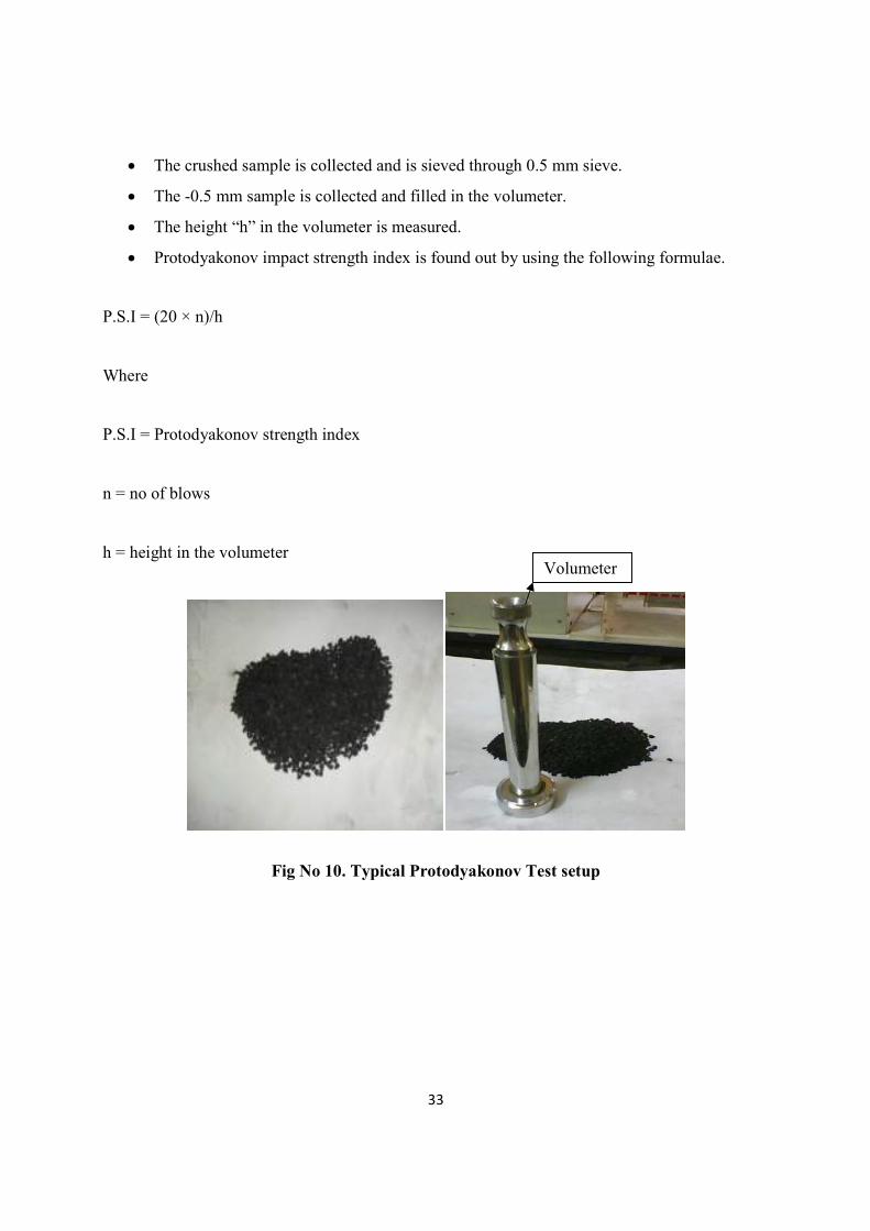
2.5.3 Uniaxial Compressive Test
(A) Before test (B) During test (C) After test
Fig No 11. Uniaxial Compressive Test
35
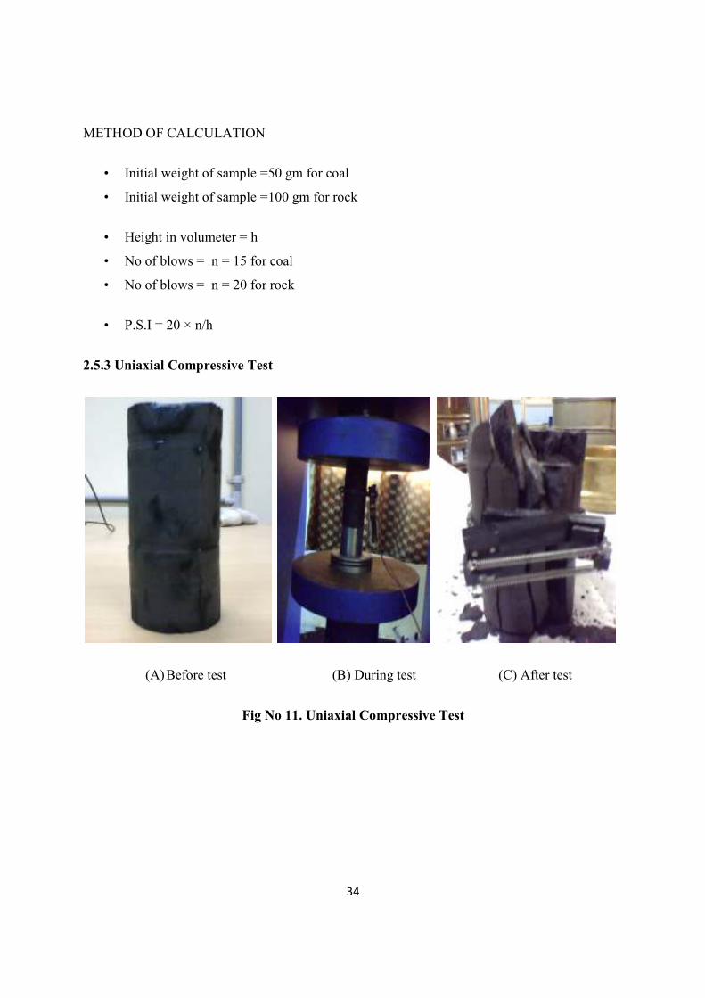
2.5.4 Tensile Test
(A) Before test (B) During test
(C) After test
Fig No 12. Tensile Test setup
36
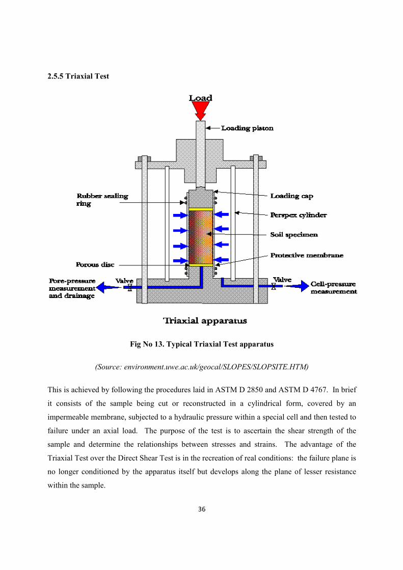
2.5.5 Triaxial Test
Fig No 13. Typical Triaxial Test apparatus
(Source: environment.uwe.ac.uk/geocal/SLOPES/SLOPSITE.HTM)
This is achieved by following the procedures laid in ASTM D 2850 and ASTM D 4767. In brief
it consists of the sample being cut or reconstructed in a cylindrical form, covered by an
impermeable membrane, subjected to a hydraulic pressure within a special cell and then tested to
failure under an axial load. The purpose of the test is to ascertain the shear strength of the
sample and determine the relationships between stresses and strains. The advantage of the
Triaxial Test over the Direct Shear Test is in the recreation of real conditions: the failure plane is
no longer conditioned by the apparatus itself but develops along the plane of lesser resistance
within the sample.
37
The control of drainage and pore pressure allows the study of the effect fluids have of the
mechanical properties of the solids in the sample. The triaxial test also allows radial strain of the
sample under load, a feature not present in consolidation tests performed with odometers.
Therefore the triaxial test may be useful in identifying deformations where the Poisson Ratio of
the material is of importance.
Composition of the Apparatus: The Triaxial Test Apparatus may be composed in various
ways, in order to ensure the most rational choice of component parts we recommend that the
following guide is followed step by step so as to identify the apparatus which most fully satisfies
all tests likely to be encountered.
Sample Dimensions: The most frequent sample diameter is 38.1 mm (1.5 inch). Larger
diameters may be necessary if the sample contains coarse grains. Small diameter samples are
preferred with fine grained soils so as to reduce the time needed for drainage and consolidation.
Sample Preparation: Samples of cohesive soil are normally taken from undisturbed specimens
by either boring or turning on a lathe. The former method is acceptable in soils of medium
consistency whilst the latter is preferred for soft or hard material. With the boring method, as
well as a Sampling Tube of suitable diameter with relative accessories, it is advisable to have a
Hand Extruder to extrude the sample from the tube. A special Electric Lathe is available for
turning samples to the required diameter. Naturally, the lathe must be equipped with Support
Platens of the same diameter as that of the required sample. Once the sample has been turned or
bored it can be cut to its correct length (two times its diameter) with level and parallel faces by
placing it in a Two-Part Split Mould and trimming the ends with a trimming knife or wire saw.
To reconstruct sand samples a Three-Part Split Former of suitable diameter is used.

38
CHAPTER: 03
MATERIALS & METHODS
Data collection
Data Analysis
39
CHAPTER 3
3.0 MATERIALS AND METHODS
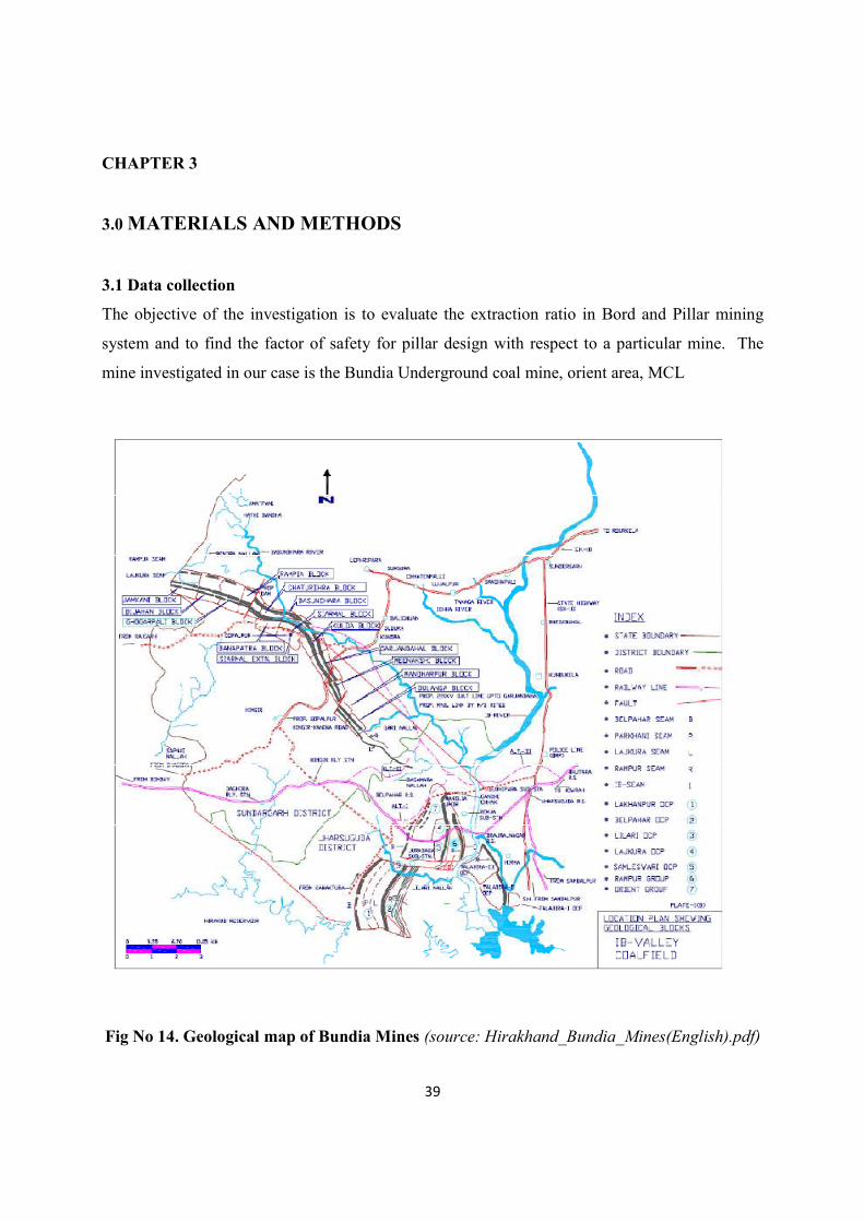
3.1 Data collection
The objective of the investigation is to evaluate the extraction ratio in Bord and Pillar mining
system and to find the factor of safety for pillar design with respect to a particular mine. The
mine investigated in our case is the Bundia Underground coal mine, orient area, MCL
Fig No 14. Geological map of Bundia Mines (source: Hirakhand_Bundia_Mines(English).pdf)

40
3.1.1 STUDY AREA PROFILE
Location (plate no.ib)
Hirakhand Bundia U/G Mine is located in Orient area of Ib Valley coalfield. It falls within the
latitude 20O 48’ 45” & 21O 48’ 30” N and longitude 83O 54’ 00” & 83O 56’ 00” E.
Communication
The area can be approached by rail as well as road. The nearest town is Brajrajngar. The state
highway passes at a distance of 10 km from the project. The nearest rail head on Howrah-
Mumbai main line of South Eastern Railways is Brajrajnagar which is about 4 km from the
block. Jharsuguda – the district headquarter is about 16 km away from the area and is well
connected by all season motor able road. Sambalpur - the head-quarter of Mahanadi Coalfield is
about 70 km away from the block and is well connected by rail and road (NH 200 & NH-10).
Topography & drainage
The area is characterized by undulating topography with general slope towards Ib River which
flows from north to south. The average elevation of the area is about 230 m from mean sea
level. Lilari nullha flows in the south. The drainage system of the area is mainly controlled by
Ib River which flows from north to south towards the eastern part of the block. Data were also
obtained from the layout of Bundia colliery such as Geological – location of seam, depth, seam
thickness and Mining – borehole data, pillar thickness etc
3.1.2 PROJECT PROFILE
(a) PROJECT BOUNDARY
North: Himgir-Rampur colliery and Unit-2 of Brajrajnagar lies in the northern side of the mine.
East: V.S.S. Nagar and Telen Kacchar basti are located adjustment to eastern boundary.
South: Ainlapali, Kantatikira and Budhihali villages are on southern side of area.
West: Samaleswari OCP and Chingriguda village are on western side of the mine

41
(b) DISTANCE FROM WATER BODIES
Ib river- 2 km
Lilari nulha- 2.5 km
Bagachhara- 2.4 km
Hirakud Reservoir- 10 km
(c) DESCRIPTION OF CORE ZONE
The core zone of the mine which includes the surface area of underground mine, mine access and
infrastructure area comes under 3 villages namely, Bundia, Kudopali and Ainlapali villages. The
part of the surface area of this mine is covered by dense vegetation. There are no places of
religious, historical and archaeological importance
(d) DESCRIPTION OF BUFFER ZONE
The buffer zone i.e. area within 10 km radius from the periphery of the U/G mine has been
developed into an industrial belt comprising of opencast mines, underground mines and various
industries. Lajkura OCP, Belpahar OCP, Samaleswari OCP, Lilari OCP, Orient U/G Mine
No.1&2, Orient U/G Mine No.3, Orient U/G Mine No.4, and Hingir-Rampur U/G mines are
located in buffer zone. Other industries situated around the buffer zone of the project area Tata
Refractories Limited, Ib Thermal Power Stations (OPGC). Howrah-Mumbai railway line (South-
Eastern Railway) passes through the buffer zone. A few reserve forests and village forests are
located in buffer zone but due to biotic interference most of the forests are found to be degraded.
The population of buffer zone including core zone is around 1,34,184
(e) GEOLOGY
i. There are three seams viz. Lajkura, Rampur and Ib seams. Rampur seam (4 sections) and Ib
seam (middle section) are being extracted in this mine.
ii. The grade of coal is ‘D’.
iii. The mineable reserves are 28.245 Mt for HR seam and 6.310 Mt for Ib Middle seam.
42
.
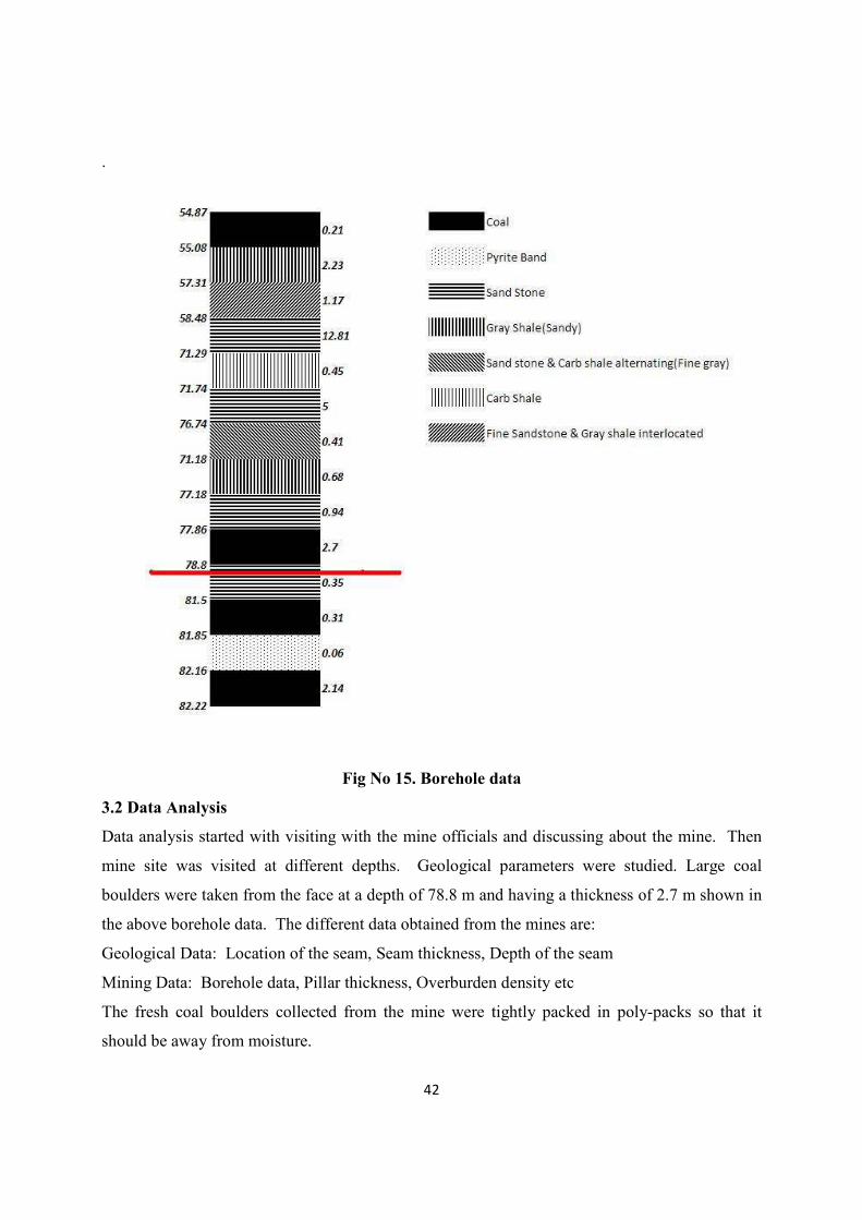
Fig No 15. Borehole data
3.2 Data Analysis
Data analysis started with visiting with the mine officials and discussing about the mine. Then
mine site was visited at different depths. Geological parameters were studied. Large coal
boulders were taken from the face at a depth of 78.8 m and having a thickness of 2.7 m shown in
the above borehole data. The different data obtained from the mines are:
Geological Data: Location of the seam, Seam thickness, Depth of the seam
Mining Data: Borehole data, Pillar thickness, Overburden density etc
The fresh coal boulders collected from the mine were tightly packed in poly-packs so that it
should be away from moisture.

43
3.2.1 Sampling Procedure
STORAGE
• The samples collected from the site is kept at a separate place.
• Some samples which will be taken for laboratory testing is kept in plastic bags.
• Plastic bags are used to protect it from moisture and the atmosphere gases.
TRANSPORTATION OF SAMPLES
• Transportation of samples is usually done in trucks, lorries etc.
• Samples which are collected in plastic bags which stop interaction of the samples with
the external atmosphere are kept in wooden boxes.
• Wooden boxes are usually preferred during the transporting of the coal samples because
they protect the samples from sunlight.
• Heat of the sun during transportation of the samples can cause fire in the coal samples if
exposed directly. Hence wooden boxes protect the samples efficiently.
• Wooden boxes also protect them from rainfall and reduce the chances of faulty samples
in the laboratory testing.
• Wooden boxes along with the plastic bags preserve the true nature of the samples from
the site to the laboratory.
Rock cores are samples of record of the existing subsurface conditions at given borehole
locations. The samples are expected to yield significant indications about the geological,
physical, and engineering nature of the subsurface.
Before carrying out Laboratory experiments coring was done. For different experiments,
appropriate cores were obtained having the corresponding L/D ratio. Then the cores were
polished by corundum powder and made ready for testing purposes
44
CHAPTER: 04
TEST RESULTS & DISCUSSIONS
Slake durability Test
Protodyakonov Test
Compressive strength Test
Tensile Test
Triaxial Test
Factor of safety
Extraction ratio
45
CHAPTER 4
4.0 TEST RESULTS AND DISCUSSIONS
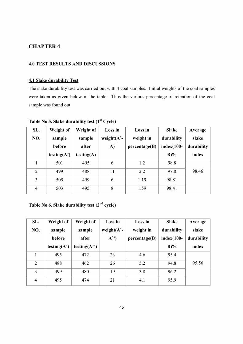
4.1 Slake durability Test
The slake durability test was carried out with 4 coal samples. Initial weights of the coal samples
were taken as given below in the table. Thus the various percentage of retention of the coal
sample was found out.
Table No 5. Slake durability test (1st Cycle)
Table No 6. Slake durability test (2nd cycle)
SL.
NO.
Weight of
sample
before
testing(A’)
Weight of
sample
after
testing(A)
Loss in
weight(A’-
A)
Loss in
weight in
percentage(B)
Slake
durability
index(100-
B)%
Average
slake
durability
index
1 501 495 6 1.2 98.8
98.46 2 499 488 11 2.2 97.8
3 505 499 6 1.19 98.81
4 503 495 8 1.59 98.41
SL.
NO.
Weight of
sample
before
testing(A’)
Weight of
sample
after
testing(A’’)
Loss in
weight(A’-
A’’)
Loss in
weight in
percentage(B)
Slake
durability
index(100-
B)%
Average
slake
durability
index
1 495 472 23 4.6 95.4
95.56 2 488 462 26 5.2 94.8
3 499 480 19 3.8 96.2
4 495 474 21 4.1 95.9
46
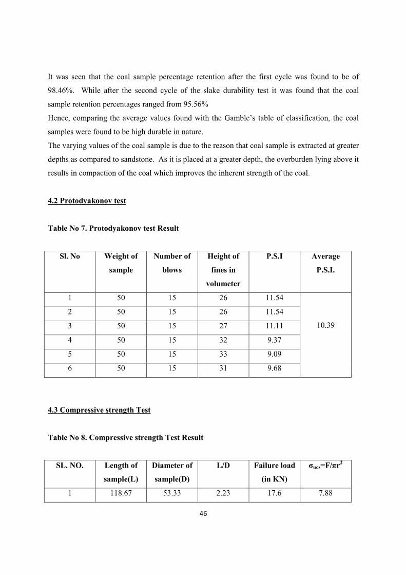
It was seen that the coal sample percentage retention after the first cycle was found to be of
98.46%. While after the second cycle of the slake durability test it was found that the coal
sample retention percentages ranged from 95.56%
Hence, comparing the average values found with the Gamble’s table of classification, the coal
samples were found to be high durable in nature.
The varying values of the coal sample is due to the reason that coal sample is extracted at greater
depths as compared to sandstone. As it is placed at a greater depth, the overburden lying above it
results in compaction of the coal which improves the inherent strength of the coal.
4.2 Protodyakonov test
Table No 7. Protodyakonov test Result
4.3 Compressive strength Test
Table No 8. Compressive strength Test Result
SL. NO. Length of
sample(L)
Diameter of
sample(D)
L/D Failure load
(in KN)
σucs=F/πr2
1 118.67 53.33 2.23 17.6 7.88
Sl. No Weight of
sample
Number of
blows
Height of
fines in
volumeter
P.S.I Average
P.S.I.
1 50 15 26 11.54
10.39
2 50 15 26 11.54
3 50 15 27 11.11
4 50 15 32 9.37
5 50 15 33 9.09
6 50 15 31 9.68

47
The above table shows the average compressive strength test of 3 coal samples. The average
compressive strength of the coal sample was found to be 7.88 Mpa.
4.4 Tensile test
Table No 9. Tensile test Result
The average tensile strength of the coal sample was found to be 3.95 Mpa. This variation in
compressive strength and tensile strength seems to be due to the fact that during coring fracture
may have been developed in the coal sample.
4.5 Triaxial test Result
Sample 1
Average diameter = 53.00 mm
Average length = 51.07 mm
Load = 20 Kg/cm2
Failure load = 30 KN
Sample 2
Average diameter = 53.64 mm
Average length = 60.13 mm
Load = 40 Kg/cm2
Failure load = 38 KN
SL. NO. Length of
sample(L)
Diameter
of
sample(D)
L/D Failure
load (in
KN)
σT=2F/πDL(in
MPa)
Average σT
1 29 53.3 0.54 11 4.53
3.95 2 39.67 53 0.75 10 3.02
3 27 53 0.51 10 4.45
4 31.8 53 0.60 10 3.78

48
Sample 3
Average diameter = 53.43 mm
Average length = 85.56 mm
Load = 60 Kg/cm2
Failure load = 46 KN
Fig No 16. Triaxial Test graph
From the above graph based on LINEAR REGRESSION,
The value of cohesion, c = 3.667 Mpa
The frictional angle = 17.3450
The Uniaxial Compressive strength = 9.974 Mpa
49
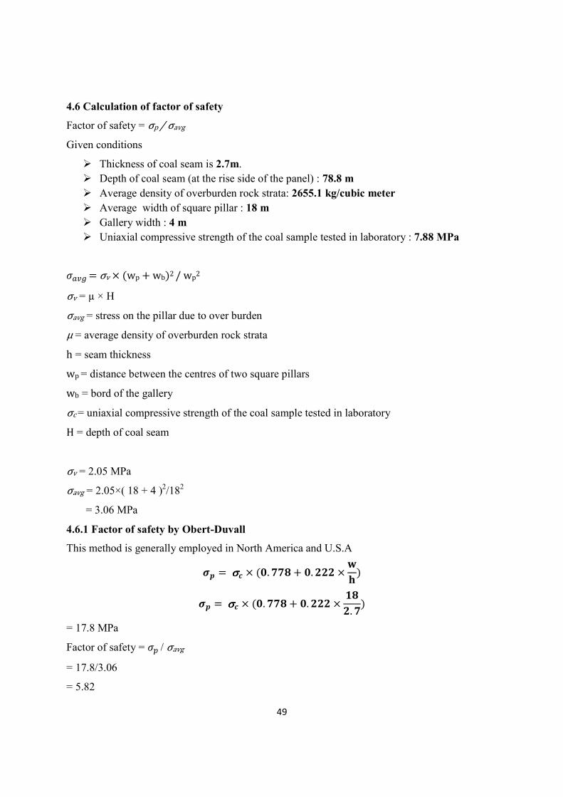
4.6 Calculation of factor of safety
Factor of safety = σp�*�σavg
Given conditions
� Thickness of coal seam is 2.7m.
� Depth of coal seam (at the rise side of the panel) : 78.8 m
� Average density of overburden rock strata: 2655.1 kg/cubic meter
� Average width of square pillar : 18 m
� Gallery width : 4 m
� Uniaxial compressive strength of the coal sample tested in laboratory : 7.88 MPa
&234 ���σv����wp���wb���*�wp���
σv = µ × H
σavg = stress on the pillar due to over burden
µ = average density of overburden rock strata
h = seam thickness
wp = distance between the centres of two square pillars
wb = bord of the gallery
σc = uniaxial compressive strength of the coal sample tested in laboratory
H = depth of coal seam
�
σv = 2.05 MPa
σavg = 2.05×( 18 + 4 )2/18
2
= 3.06 MPa
4.6.1 Factor of safety by Obert-Duvall
This method is generally employed in North America and U.S.A
;< ��σσσσ= � �>� ??@ � >� AAA �BC�
;< ��σσσσ= � �>� ??@ � >� AAA �D@A� ?
�
= 17.8 MPa
Factor of safety = &� / σavg�
= 17.8/3.06
= 5.82
50
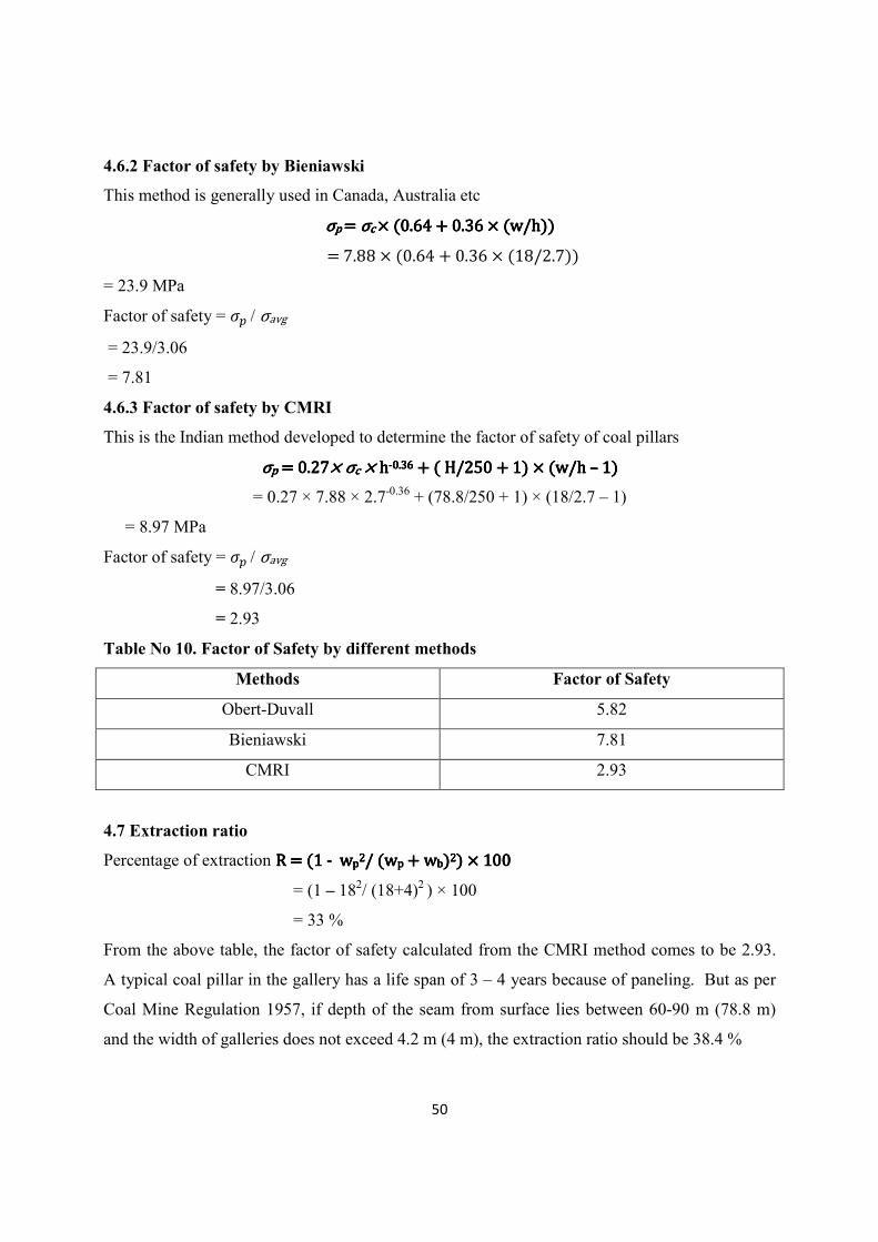
4.6.2 Factor of safety by Bieniawski
This method is generally used in Canada, Australia etc
σσσσp�p�p�p���������σσσσc�c�c�c������64������6����w*h�������64������6����w*h�������64������6����w*h�������64������6����w*h��
�����������88������64������6�����8*������
= 23.9 MPa
Factor of safety = &� / σavg
= 23.9/3.06
= 7.81
4.6.3 Factor of safety by CMRI
This is the Indian method developed to determine the factor of safety of coal pillars
σσσσpppp������������������������������������σσσσcccc������������hhhh----���6���6���6���6��������H*�5����������w*h�����H*�5����������w*h�����H*�5����������w*h�����H*�5����������w*h�––––����������������
= 0.27 × 7.88 × 2.7-0.36 + (78.8/250 + 1) × (18/2.7 – 1)
= 8.97 MPa
Factor of safety = &� / σavg
= 8.97/3.06
= 2.93
Table No 10. Factor of Safety by different methods
Methods Factor of Safety
Obert-Duvall 5.82
Bieniawski 7.81
CMRI 2.93
4.7 Extraction ratio
Percentage of extraction R������R������R������R������----��������wwwwpppp����*��w*��w*��w*��wpppp������w��w��w��wbbbb������������������������������������
= (1 – 182/ (18+4)2 ) × 100
= 33 %
From the above table, the factor of safety calculated from the CMRI method comes to be 2.93.
A typical coal pillar in the gallery has a life span of 3 – 4 years because of paneling. But as per
Coal Mine Regulation 1957, if depth of the seam from surface lies between 60-90 m (78.8 m)
and the width of galleries does not exceed 4.2 m (4 m), the extraction ratio should be 38.4 %
51
CHAPTER: 05
CONCLUSION
CONCLUSION
FUTURE RECOMMENDATION
52
CHAPTER 5
5.1 CONCLUSION
The key to the successful Bord and Pillar mining is selecting the optimum pillar size. If the
pillars are too small the mine will collapse. If the pillars are too large then significant quantities
of valuable material will be left behind reducing the profitability of the mine. The most
important parameter before designing a pillar is the Safety factor.
The observed safety factor for the coal pillar as per the CMRI method comes to be: 2.93
The extraction percentage was calculated to be 33%
The typical lifespan of a coal pillar is around 3-4 years due to paneling. So the recommended
safety factor for the coal pillars should be around 1.5-2. But the observed safety factor is 2.93.
So it gives a possibility of decreasing the safety factor to around 2. This would increase the
extraction percentage without compromising the safety factor
5.2 FUTURE RECOMMENDATION
In this investigation a few aspects of Bord and Pillar mining system such as seam thickness,
depth of the seam, density of the overburden are taken into account to find the safety factor and
extraction percentage. However, there are various factors such as roof pressure, effect of
discontinuities, the horizontal and vertical stresses that affect the pillar strength. So it is strongly
recommended that the following may be taken into consideration in future.
a) The samples have not been taken from different depths; the samples have been taken just
from a single depth and field conditions are not taken into consideration
b) Limited tests were carried out
So further tests and analysis should be carried out to find the correlation between extraction
percentage and safety factor

53
REFERENCES
� Singh, R.D., “Principles And Practices Of Modern Coal Mining”, New Age
International Limited Publishers, 1st Edition, 2005, Chapter 6, pp. 156-18
� Deshmukh, D.J., “Elements Of Mining Technology”, Denett & Co. Publication,
Vol. 1, 7th
Edition, 1995, Chapter 12, Page no.367-386
� http://www.faculty.uaf.edu/ffrg/min454/Handout4_MIN454.pdf
� Lombard, H.E., Fourie, G.A., Cox, A.J., DU Plesis, A.G. and Wilson, R.B.
Review of access design and mining method of the 44E room and pillar mine
design, Interim Report, SRK-Turgis. 2001. pp. 1–10.
� http://www.strataengineering.com.au/client_images/782664.pdf
� http://www.maden.org.tr/resimler/ekler/37168031d88451c_ek.pdf
� http://researchspace.csir.co.za/dspace/bitstream/10204/1419/1/COL337.pdf
� http://www.saimm.co.za/Journal/v091n01p027.pdf
� http://www.rokdok.com/mining/pubs/vail.pdf
� Bieniawski, Z. T., 1984, Rock Mechanics Design in Mining and Tunneling, A. A.
Balkema.
� Das, M N, 1986. Influence of width to height ratio on post-failure behavior of
coal, International Journal of Mining and Geological Engineering, 4:79-87.
� Madden, B J, 1987. “Coal pillar design – Can increased extraction be achieved
safely?” Paper presented to Mine Safety and Health Congress, Johannesburg