Embed Size (px)
Citation preview

Contact details:C.S.U.T. SPETECH Sp. z o.o.EUROPARTNER® TEAMLABORATORY OF SEALING MATERIALS
Poland, 43-382 Bielsko-Biała, ul. Szyprów 17tel. +48 33 8184133, fax +48 33 [email protected], [email protected]
EUROPARTNER®
System and hardware requirements:Windows XP, Vista, 7, 8, 8.1 64/32 bit
graphic card with OpenGL supportHD ca. 500MB free space
LABORATORY OF SEALING MATERIALSThe majority of coefficients used in calculations make in the EUROPARTNER® program and contained in the database is determined on our laboratory test stands. In 1997 the Laboratory commenced its activity as an independent research unit established at SPETECH. It contain implemented and maintained Quality Management System based on the regulations of EN ISO/IEC 17025 Std. The Laboratory has necessary research facilities and qualified staff implementing, within the framework of applicable procedures, a relevant research programme. Due to the fact that the parent company of the laboratory is SPETECH, performed tests largely focus on seals produced by it.
OFFERED TEST METHODSBased on EN 13555:• Qsmax and EG at ambient temperature• Qsmax and EG at temperatures elevated to 800°C• PQR at ambient temperature• PQR at temperatures elevated to 800°C• Qmin(L) and Qsmin(L) at ambient temperature• others to be agreedBased on ASTM:• F 586-79 determination of coefficients m and y• F 36-03 determination of compressibility and elastic recovery• F 38-00 B determination of relaxation and creeping
The laboratory is equipped with a coordinate measuring arm. Thanks to this mechanism it is possible to make a very precise measurements of flange joint geometry, mostly on physical installations, and create 3D models of, e.g.:• flatness of faying surfaces,• non-parallelism of these surfaces,• angular deformation of flanges.Knowledge of exact geometry, especially in case of large diameters, significantly contributes to find a relevant solution of tightness problems. In cases of large of calculation issue complication, FEM methods are successfully used.
The laboratory has been approved by TÜV Rheinland Polska and Polish Office of Technical Inspections (UDT).
www.europartner.spetech.eu
EUROPARTNER®
EUROPARTNER® CALCULATION PROGRAM an advanced tool for joint designing
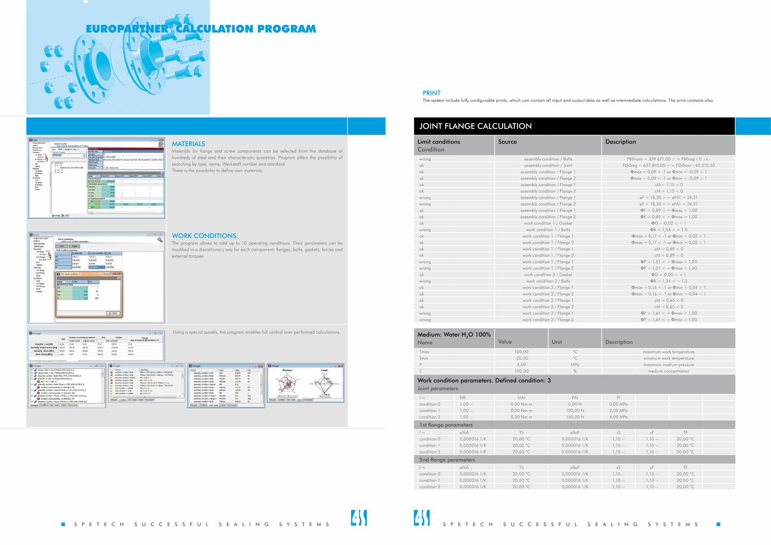
PRINTThe system include fully configurable prints, which can contain all input and output data as well as intermediate calculations. The print contains also.
JOINT FLANGE CALCULATION
Limit conditionsCondition
Source Description
wrong assembly condition / Bolts FB0nom = 359 671,00 > = FB0reg / )1 - ε -ok assembly condition / Joint FG0reg = 637 810,00 > = FG0min - 40 310,50ok assembly condition / Flange 1 Φmax = 0,09 < -1 or Φmin = -0,09 > 1ok assembly condition / Flange 2 Φmax = 0,09 < -1 or Φmin = -0,09 > 1ok assembly condition / Flange 1 cM = 1,15 < 0ok assembly condition / Flange 2 cM = 1,15 < 0wrong assembly condition / Flange 1 eF = 18,20 > = eFA1 = 24,21wrong assembly condition / Flange 2 eF = 18,20 > = eFA1 = 24,21ok assembly condition / Flange 1 ΦF = 0,89 < = Φmax = 1,00ok assembly condition / Flange 2 ΦF = 0,89 < = Φmax = 1,00ok work condition 1 / Gasket ΦG = 0,02 < = 1wrong work condition 1 / Bolts ΦB = 1,54 < = 1.0ok work condition 1 / Flange 1 Φmax = 0,17 < -1 or Φmin = 0,02 > 1ok work condition 1 / Flange 2 Φmax = 0,17 < -1 or Φmin = 0,02 > 1ok work condition 1 / Flange 1 cM = 0,89 < 0ok work condition 1 / Flange 2 cM = 0,89 < 0wrong work condition 1 / Flange 1 ΦF = 1,51 < = Φmax = 1,00wrong work condition 1 / Flange 2 ΦF = 1,51 < = Φmax = 1,00ok work condition 2 / Gasket ΦG = 0,00 < = 1wrong work condition 2 / Bolts ΦB = 1,24 < = 1.0ok work condition 2 / Flange 1 Φmax = 0,16 < -1 or Φmin = 0,04 > 1ok work condition 2 / Flange 2 Φmax = 0,16 < -1 or Φmin = 0,04 > 1ok work condition 2 / Flange 1 cM = 0,65 < 0ok work condition 2 / Flange 2 cM = 0,65 < 0wrong work condition 2 / Flange 1 ΦF = 1,61 < = Φmax = 1,00wrong work condition 2 / Flange 2 ΦF = 1,61 < = Φmax = 1,00
Medium: Water H2O 100%Name Value Unit Description
Tmax 100,00 *C maximum work temperatureTmin -20,00 *C minimum work temperatureP 4,00 MPa maximum medium pressureC 100,00 % medium concentration
Work condition parameters. Defined condition: 3Joint parameters
I = NR MAI FAI PIcondition 0 1,00 -- 0,00 Nm m 0,00 N 0,00 MPacondition 1 1,00 -- 0,00 Nm m 150,00 N 2,00 MPacondition 2 1,00 -- 0,00 Nm m 150,00 N 4,00 MPa
1st flange parametersI = alfaS TS aflaF xS xF TFcondition 0 0,000016 1/K 20,00 *C 0,000016 1/K 1,10 -- 1,10 -- 20,00 *Ccondition 1 0,000016 1/K 20,00 *C 0,000016 1/K 1,10 -- 1,10 -- 20,00 *Ccondition 2 0,000016 1/K 20,00 *C 0,000016 1/K 1,10 -- 1,10 -- 20,00 *C
2nd flange parametersI = alfaS TS aflaF xS xF TFcondition 0 0,000016 1/K 20,00 *C 0,000016 1/K 1,10 -- 1,10 -- 20,00 *Ccondition 1 0,000016 1/K 20,00 *C 0,000016 1/K 1,10 -- 1,10 -- 20,00 *Ccondition 2 0,000016 1/K 20,00 *C 0,000016 1/K 1,10 -- 1,10 -- 20,00 *C
Stand acc. to EN13555 Stand acc. to ASTM F 586-79 Stand acc. to EN 13555 Measurement arm
Based on VDI 2440:• determination of flat gasket leakage acc. TA-Luft• determination of stuffing box seal leakage acc. to TA-Luft
Based on EN 61340-2-3:• determining the resistance and resistivity
LB – 124/02
www.tuv.com210/A13/5952
S P E T E C H S U C C E S S F U L S E A L I N G S Y S T E M S
LDT

Engineering software EUROPARTNER® developed in SPETECH is used by designers and service companies to select proper flange joint seal and calculate correct tension and tightening torque. Moreover, it allows to calculate the whole flange joint as regards strength. The program contains several calculation algorithms compliant with:
• EN 1591-1:2013
• EN 1591-1:2009
• EN 1591-1:2001
• WUDT-UC-WO-/19:10.2003
• ASME Code s. VIII
• AD 2000 Merkblatt B7/B8
• EN 13445-3 Annex GUsing the algorithm EN 1591-1HA1:2009 or ...2013 the designer, by selection of appropriate tightness class, can influence reduction of emissions generated by the selected seal. Thus, the joint is designed in the way compliant with requirements of such environmental protection regulations as IPPC Directive, TA-Luft and Clean Air Act. Use of the EUROPARTNER® program as an engineering and expert tool constitutes a part of generally applied and recommended ”best available techniques” and “good engineering practices”.
Advantages:1. Enormous database of geometrical values of gaskets, flanges, faces and bolts and characteristic quantities of steel materials enables fast designing without looking these values up in relevant standards.2. Automatic, real time calculation of output quantities that enables continuous control over the correctness of entered data.3. Adapted rule of entered data hints maximization (expert function) however, the program finally does not impose anything. Such functionality gives the designer the possibility to perform necessary modifications of standard components.4. Full direct control through the critical data panels system, allowing to check the whole project correctness on a current basis.5. Configurable prints taking into account all input, output and intermediate data. They also contain all important drawings of joint components.6. The same user interface regardless of calculation standard used.7. Four language versions: Polish, English, German and Czech.
MEDIUMSeal selection depending on medium and its operating parameters. The database contains about 700 types of media. Possibility to preset medium concentration and limit temperatures and pressure for the design. Tightness class plays the key role in gasket selection. By proper selection the designer influences the level of emissions from the designed joint.
GASKET TYPEA particular gasket type is selected automatically by the program on the basis of specified limiting conditions or manually by the designer. The program contains the database of SPETECH seals and those mentioned in a given standard. It is possible to design and calculate any gasket and the program producer can add seals of other companies.
FLANGE TYPEDesigning of flanges and faces, also for apparatuses, by manual entering of geometrical data flanges and pipeline faces can be selected from the database of geometrical values compliant with EN, DIN, ASME, PN standards. Fully editable dimensions, possible change of the units of measure.
BOLTSCorrect selection of bolts, their size, number and material significantly affects the possibility of gasket forming and its operation. The program allows such a modification of all bolt-related quantities so as to obtain as a result appropriate assembly and operational tensions, at minimal number and size of bolts, and a reasonable, from the strength conditions point of view, material selection. The dimensions tab gives the possibility to determine the normative geometry of bolts. Depending on selected calculation standard, additional editable fields connected, for example, with the method of bolts tightening or with assumed friction coefficient on the bolt thread and head, appear in the bolts section.
MATERIALSMaterials for flange and screw components can be selected from the database of hundreds of steel and their characteristic quantities. Program offers the possibility of searching by type, name, Werkstoff number and standard.There is the possibility to define own materials.
WORK CONDITIONSThe program allows to add up to 10 operating conditions. Their parameters can be modified in a discretionary way for each component: flanges, bolts, gaskets, forces and external torques
Using a special panels, the program enables full control over performed calculations.
EUROPARTNER® CALCULATION PROGRAM EUROPARTNER® CALCULATION PROGRAM EUROPARTNER® CALCULATION PROGRAM
S P E T E C H S U C C E S S F U L S E A L I N G S Y S T E M S
Contact details:C.S.U.T. SPETECH Sp. z o.o.EUROPARTNER® TEAMLABORATORY OF SEALING MATERIALS
Poland, 43-382 Bielsko-Biała, ul. Szyprów 17tel. +48 33 8184133, fax +48 33 [email protected], [email protected]
EUROPARTNER®
System and hardware requirements:Windows XP, Vista, 7, 8, 8.1 64/32 bit
graphic card with OpenGL supportHD ca. 500MB free space
LABORATORY OF SEALING MATERIALSThe majority of coefficients used in calculations make in the EUROPARTNER® program and contained in the database is determined on our laboratory test stands. In 1997 the Laboratory commenced its activity as an independent research unit established at SPETECH. It contain implemented and maintained Quality Management System based on the regulations of EN ISO/IEC 17025 Std. The Laboratory has necessary research facilities and qualified staff implementing, within the framework of applicable procedures, a relevant research programme. Due to the fact that the parent company of the laboratory is SPETECH, performed tests largely focus on seals produced by it.
OFFERED TEST METHODSBased on EN 13555:• Qsmax and EG at ambient temperature• Qsmax and EG at temperatures elevated to 800°C• PQR at ambient temperature• PQR at temperatures elevated to 800°C• Qmin(L) and Qsmin(L) at ambient temperature• others to be agreedBased on ASTM:• F 586-79 determination of coefficients m and y• F 36-03 determination of compressibility and elastic recovery• F 38-00 B determination of relaxation and creeping
The laboratory is equipped with a coordinate measuring arm. Thanks to this mechanism it is possible to make a very precise measurements of flange joint geometry, mostly on physical installations, and create 3D models of, e.g.:• flatness of faying surfaces,• non-parallelism of these surfaces,• angular deformation of flanges.Knowledge of exact geometry, especially in case of large diameters, significantly contributes to find a relevant solution of tightness problems. In cases of large of calculation issue complication, FEM methods are successfully used.
The laboratory has been approved by TÜV Rheinland Polska and Polish Office of Technical Inspections (UDT).
www.europartner.spetech.eu
EUROPARTNER®
EUROPARTNER® CALCULATION PROGRAM an advanced tool for joint designing
PRINTThe system include fully configurable prints, which can contain all input and output data as well as intermediate calculations. The print contains also.
JOINT FLANGE CALCULATION
Limit conditionsCondition
Source Description
wrong assembly condition / Bolts FB0nom = 359 671,00 > = FB0reg / )1 - ε -ok assembly condition / Joint FG0reg = 637 810,00 > = FG0min - 40 310,50ok assembly condition / Flange 1 Φmax = 0,09 < -1 or Φmin = -0,09 > 1ok assembly condition / Flange 2 Φmax = 0,09 < -1 or Φmin = -0,09 > 1ok assembly condition / Flange 1 cM = 1,15 < 0ok assembly condition / Flange 2 cM = 1,15 < 0wrong assembly condition / Flange 1 eF = 18,20 > = eFA1 = 24,21wrong assembly condition / Flange 2 eF = 18,20 > = eFA1 = 24,21ok assembly condition / Flange 1 ΦF = 0,89 < = Φmax = 1,00ok assembly condition / Flange 2 ΦF = 0,89 < = Φmax = 1,00ok work condition 1 / Gasket ΦG = 0,02 < = 1wrong work condition 1 / Bolts ΦB = 1,54 < = 1.0ok work condition 1 / Flange 1 Φmax = 0,17 < -1 or Φmin = 0,02 > 1ok work condition 1 / Flange 2 Φmax = 0,17 < -1 or Φmin = 0,02 > 1ok work condition 1 / Flange 1 cM = 0,89 < 0ok work condition 1 / Flange 2 cM = 0,89 < 0wrong work condition 1 / Flange 1 ΦF = 1,51 < = Φmax = 1,00wrong work condition 1 / Flange 2 ΦF = 1,51 < = Φmax = 1,00ok work condition 2 / Gasket ΦG = 0,00 < = 1wrong work condition 2 / Bolts ΦB = 1,24 < = 1.0ok work condition 2 / Flange 1 Φmax = 0,16 < -1 or Φmin = 0,04 > 1ok work condition 2 / Flange 2 Φmax = 0,16 < -1 or Φmin = 0,04 > 1ok work condition 2 / Flange 1 cM = 0,65 < 0ok work condition 2 / Flange 2 cM = 0,65 < 0wrong work condition 2 / Flange 1 ΦF = 1,61 < = Φmax = 1,00wrong work condition 2 / Flange 2 ΦF = 1,61 < = Φmax = 1,00
Medium: Water H2O 100%Name Value Unit Description
Tmax 100,00 *C maximum work temperatureTmin -20,00 *C minimum work temperatureP 4,00 MPa maximum medium pressureC 100,00 % medium concentration
Work condition parameters. Defined condition: 3Joint parameters
I = NR MAI FAI PIcondition 0 1,00 -- 0,00 Nm m 0,00 N 0,00 MPacondition 1 1,00 -- 0,00 Nm m 150,00 N 2,00 MPacondition 2 1,00 -- 0,00 Nm m 150,00 N 4,00 MPa
1st flange parametersI = alfaS TS aflaF xS xF TFcondition 0 0,000016 1/K 20,00 *C 0,000016 1/K 1,10 -- 1,10 -- 20,00 *Ccondition 1 0,000016 1/K 20,00 *C 0,000016 1/K 1,10 -- 1,10 -- 20,00 *Ccondition 2 0,000016 1/K 20,00 *C 0,000016 1/K 1,10 -- 1,10 -- 20,00 *C
2nd flange parametersI = alfaS TS aflaF xS xF TFcondition 0 0,000016 1/K 20,00 *C 0,000016 1/K 1,10 -- 1,10 -- 20,00 *Ccondition 1 0,000016 1/K 20,00 *C 0,000016 1/K 1,10 -- 1,10 -- 20,00 *Ccondition 2 0,000016 1/K 20,00 *C 0,000016 1/K 1,10 -- 1,10 -- 20,00 *C
Stand acc. to EN13555 Stand acc. to ASTM F 586-79 Stand acc. to EN 13555 Measurement arm
Based on VDI 2440:• determination of flat gasket leakage acc. TA-Luft• determination of stuffing box seal leakage acc. to TA-Luft
Based on EN 61340-2-3:• determining the resistance and resistivity
LB – 124/02
www.tuv.com210/A13/5952
S P E T E C H S U C C E S S F U L S E A L I N G S Y S T E M S
LDT
Engineering software EUROPARTNER® developed in SPETECH is used by designers and service companies to select proper flange joint seal and calculate correct tension and tightening torque. Moreover, it allows to calculate the whole flange joint as regards strength. The program contains several calculation algorithms compliant with:
• EN 1591-1:2013
• EN 1591-1:2009
• EN 1591-1:2001
• WUDT-UC-WO-/19:10.2003
• ASME Code s. VIII
• AD 2000 Merkblatt B7/B8
• EN 13445-3 Annex GUsing the algorithm EN 1591-1HA1:2009 or ...2013 the designer, by selection of appropriate tightness class, can influence reduction of emissions generated by the selected seal. Thus, the joint is designed in the way compliant with requirements of such environmental protection regulations as IPPC Directive, TA-Luft and Clean Air Act. Use of the EUROPARTNER® program as an engineering and expert tool constitutes a part of generally applied and recommended ”best available techniques” and “good engineering practices”.
Advantages:1. Enormous database of geometrical values of gaskets, flanges, faces and bolts and characteristic quantities of steel materials enables fast designing without looking these values up in relevant standards.2. Automatic, real time calculation of output quantities that enables continuous control over the correctness of entered data.3. Adapted rule of entered data hints maximization (expert function) however, the program finally does not impose anything. Such functionality gives the designer the possibility to perform necessary modifications of standard components.4. Full direct control through the critical data panels system, allowing to check the whole project correctness on a current basis.5. Configurable prints taking into account all input, output and intermediate data. They also contain all important drawings of joint components.6. The same user interface regardless of calculation standard used.7. Four language versions: Polish, English, German and Czech.
MEDIUMSeal selection depending on medium and its operating parameters. The database contains about 700 types of media. Possibility to preset medium concentration and limit temperatures and pressure for the design. Tightness class plays the key role in gasket selection. By proper selection the designer influences the level of emissions from the designed joint.
GASKET TYPEA particular gasket type is selected automatically by the program on the basis of specified limiting conditions or manually by the designer. The program contains the database of SPETECH seals and those mentioned in a given standard. It is possible to design and calculate any gasket and the program producer can add seals of other companies.
FLANGE TYPEDesigning of flanges and faces, also for apparatuses, by manual entering of geometrical data flanges and pipeline faces can be selected from the database of geometrical values compliant with EN, DIN, ASME, PN standards. Fully editable dimensions, possible change of the units of measure.
BOLTSCorrect selection of bolts, their size, number and material significantly affects the possibility of gasket forming and its operation. The program allows such a modification of all bolt-related quantities so as to obtain as a result appropriate assembly and operational tensions, at minimal number and size of bolts, and a reasonable, from the strength conditions point of view, material selection. The dimensions tab gives the possibility to determine the normative geometry of bolts. Depending on selected calculation standard, additional editable fields connected, for example, with the method of bolts tightening or with assumed friction coefficient on the bolt thread and head, appear in the bolts section.
MATERIALSMaterials for flange and screw components can be selected from the database of hundreds of steel and their characteristic quantities. Program offers the possibility of searching by type, name, Werkstoff number and standard.There is the possibility to define own materials.
WORK CONDITIONSThe program allows to add up to 10 operating conditions. Their parameters can be modified in a discretionary way for each component: flanges, bolts, gaskets, forces and external torques
Using a special panels, the program enables full control over performed calculations.
EUROPARTNER® CALCULATION PROGRAM EUROPARTNER® CALCULATION PROGRAM EUROPARTNER® CALCULATION PROGRAM
S P E T E C H S U C C E S S F U L S E A L I N G S Y S T E M S

Contact details:C.S.U.T. SPETECH Sp. z o.o.EUROPARTNER® TEAMLABORATORY OF SEALING MATERIALS
Poland, 43-382 Bielsko-Biała, ul. Szyprów 17tel. +48 33 8184133, fax +48 33 [email protected], [email protected]
EUROPARTNER®
System and hardware requirements:Windows XP, Vista, 7, 8, 8.1 64/32 bit
graphic card with OpenGL supportHD ca. 500MB free space
LABORATORY OF SEALING MATERIALSThe majority of coefficients used in calculations make in the EUROPARTNER® program and contained in the database is determined on our laboratory test stands. In 1997 the Laboratory commenced its activity as an independent research unit established at SPETECH. It contain implemented and maintained Quality Management System based on the regulations of EN ISO/IEC 17025 Std. The Laboratory has necessary research facilities and qualified staff implementing, within the framework of applicable procedures, a relevant research programme. Due to the fact that the parent company of the laboratory is SPETECH, performed tests largely focus on seals produced by it.
OFFERED TEST METHODSBased on EN 13555:• Qsmax and EG at ambient temperature• Qsmax and EG at temperatures elevated to 800°C• PQR at ambient temperature• PQR at temperatures elevated to 800°C• Qmin(L) and Qsmin(L) at ambient temperature• others to be agreedBased on ASTM:• F 586-79 determination of coefficients m and y• F 36-03 determination of compressibility and elastic recovery• F 38-00 B determination of relaxation and creeping
The laboratory is equipped with a coordinate measuring arm. Thanks to this mechanism it is possible to make a very precise measurements of flange joint geometry, mostly on physical installations, and create 3D models of, e.g.:• flatness of faying surfaces,• non-parallelism of these surfaces,• angular deformation of flanges.Knowledge of exact geometry, especially in case of large diameters, significantly contributes to find a relevant solution of tightness problems. In cases of large of calculation issue complication, FEM methods are successfully used.
The laboratory has been approved by TÜV Rheinland Polska and Polish Office of Technical Inspections (UDT).
www.europartner.spetech.eu
EUROPARTNER®
EUROPARTNER® CALCULATION PROGRAM an advanced tool for joint designing
PRINTThe system include fully configurable prints, which can contain all input and output data as well as intermediate calculations. The print contains also.
JOINT FLANGE CALCULATION
Limit conditionsCondition
Source Description
wrong assembly condition / Bolts FB0nom = 359 671,00 > = FB0reg / )1 - ε -ok assembly condition / Joint FG0reg = 637 810,00 > = FG0min - 40 310,50ok assembly condition / Flange 1 Φmax = 0,09 < -1 or Φmin = -0,09 > 1ok assembly condition / Flange 2 Φmax = 0,09 < -1 or Φmin = -0,09 > 1ok assembly condition / Flange 1 cM = 1,15 < 0ok assembly condition / Flange 2 cM = 1,15 < 0wrong assembly condition / Flange 1 eF = 18,20 > = eFA1 = 24,21wrong assembly condition / Flange 2 eF = 18,20 > = eFA1 = 24,21ok assembly condition / Flange 1 ΦF = 0,89 < = Φmax = 1,00ok assembly condition / Flange 2 ΦF = 0,89 < = Φmax = 1,00ok work condition 1 / Gasket ΦG = 0,02 < = 1wrong work condition 1 / Bolts ΦB = 1,54 < = 1.0ok work condition 1 / Flange 1 Φmax = 0,17 < -1 or Φmin = 0,02 > 1ok work condition 1 / Flange 2 Φmax = 0,17 < -1 or Φmin = 0,02 > 1ok work condition 1 / Flange 1 cM = 0,89 < 0ok work condition 1 / Flange 2 cM = 0,89 < 0wrong work condition 1 / Flange 1 ΦF = 1,51 < = Φmax = 1,00wrong work condition 1 / Flange 2 ΦF = 1,51 < = Φmax = 1,00ok work condition 2 / Gasket ΦG = 0,00 < = 1wrong work condition 2 / Bolts ΦB = 1,24 < = 1.0ok work condition 2 / Flange 1 Φmax = 0,16 < -1 or Φmin = 0,04 > 1ok work condition 2 / Flange 2 Φmax = 0,16 < -1 or Φmin = 0,04 > 1ok work condition 2 / Flange 1 cM = 0,65 < 0ok work condition 2 / Flange 2 cM = 0,65 < 0wrong work condition 2 / Flange 1 ΦF = 1,61 < = Φmax = 1,00wrong work condition 2 / Flange 2 ΦF = 1,61 < = Φmax = 1,00
Medium: Water H2O 100%Name Value Unit Description
Tmax 100,00 *C maximum work temperatureTmin -20,00 *C minimum work temperatureP 4,00 MPa maximum medium pressureC 100,00 % medium concentration
Work condition parameters. Defined condition: 3Joint parameters
I = NR MAI FAI PIcondition 0 1,00 -- 0,00 Nm m 0,00 N 0,00 MPacondition 1 1,00 -- 0,00 Nm m 150,00 N 2,00 MPacondition 2 1,00 -- 0,00 Nm m 150,00 N 4,00 MPa
1st flange parametersI = alfaS TS aflaF xS xF TFcondition 0 0,000016 1/K 20,00 *C 0,000016 1/K 1,10 -- 1,10 -- 20,00 *Ccondition 1 0,000016 1/K 20,00 *C 0,000016 1/K 1,10 -- 1,10 -- 20,00 *Ccondition 2 0,000016 1/K 20,00 *C 0,000016 1/K 1,10 -- 1,10 -- 20,00 *C
2nd flange parametersI = alfaS TS aflaF xS xF TFcondition 0 0,000016 1/K 20,00 *C 0,000016 1/K 1,10 -- 1,10 -- 20,00 *Ccondition 1 0,000016 1/K 20,00 *C 0,000016 1/K 1,10 -- 1,10 -- 20,00 *Ccondition 2 0,000016 1/K 20,00 *C 0,000016 1/K 1,10 -- 1,10 -- 20,00 *C
Stand acc. to EN13555 Stand acc. to ASTM F 586-79 Stand acc. to EN 13555 Measurement arm
Based on VDI 2440:• determination of flat gasket leakage acc. TA-Luft• determination of stuffing box seal leakage acc. to TA-Luft
Based on EN 61340-2-3:• determining the resistance and resistivity
LB – 124/02
www.tuv.com210/A13/5952
S P E T E C H S U C C E S S F U L S E A L I N G S Y S T E M S
LDT