Embed Size (px)
Citation preview

Please note, this modification requires soldering skill at board level and involves removing surface mount components. This modification will also void your warranty and all responsibility resides with the person
making the modification.
With the release of the Eureka HUB set cars we have been provided with some highly detailed carriages but unfortunately, the wiring is a little behind the ball.
This is partly due to a factory wiring fault and also due to the fact you can’t control the third red marker light on the rear of the train. The factory fault also means that the marker lights are on on the wrong end of the train under DC. While correcting this is not critical under DCC operations but if you wish to operate on DC as well as DCC, is worth doing.
Thanks go to Marcus Amman for covering this on his website. See method 3 athttp://members.optusnet.com.au/nswmn/HUBMod.htm for more information on this method which is also incorporated into this modification.
While the provision of three red marker lights on the rear of the train is prototypically correct, the lower third one was only ever lit under special circumstances to indicate that the next train was a special and not in the timetable. When illuminated red, the next train was following while a white light indicated that the next train was coming from the opposite direction. Back before portable communications (radios and mobile phones), this light informed people working on or near a single line track to a train that was not in the timetable and hence not expected by the workers.
This modification will allow you to use your DCC system to set which end of your train the marker lights are illuminated and also allow you to indicate whether or not a special train is following.
Parts required:
2 x TCS FL2.Blue, green and violet decoder wire.Heat shrink tubing.Styrene and black paint (optional)
Eureka HUB Set TCS FL2 InstallBen O’Malley [email protected]
BEOM 09/04/2013 V1.0 Page 1

Start by removing the body, this is a simple job of just pulling the sides outwards and letting the underframe fall free.
While most of this work could be done with the main circuit board in place it is safer to remove it while working on it and as it does need to be removed to allow access to modify the factory wiring it is easier to just remove it completely.
Start by removing all the black retaining caps and freeing all the wires. Remove the two screws and lift the main circuit board clear. This will allow access to remove the three screws in the bottom of the interior. With the interior tilted clear, swap the red and black wires connected to “R1” and “L1” as per Marcus’s guide.
Reinstall the interior and set the underframe aside for now.
On the main circuit board remove the two diodes marked as “D1” and “D2”, these provide the directional power to the voltage regulator for the red marker lights.
Arrows showing the two diodes that need to be removed
I chose to remove the 8 pin sockets to provide a cleaner location to solder the decoder wires too. This is easily achieved by heating each socket and gently pushing the socket out with the soldering iron, once it is clear, a little tap of the board will generally knock the socket out and clear.
Also take the opportunity to tin the connection points at each end of the circuit board so you can solder the wires back on for a better connection then provided by the black caps.
Eureka HUB Set TCS FL2 InstallBen O’Malley [email protected]
BEOM 09/04/2013 V1.0 Page 2
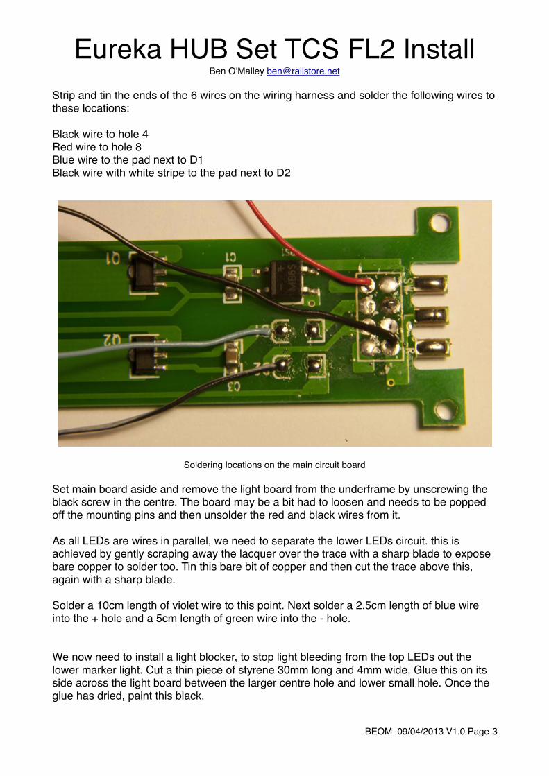
Strip and tin the ends of the 6 wires on the wiring harness and solder the following wires to these locations:
Black wire to hole 4Red wire to hole 8Blue wire to the pad next to D1Black wire with white stripe to the pad next to D2
Soldering locations on the main circuit board
Set main board aside and remove the light board from the underframe by unscrewing the black screw in the centre. The board may be a bit had to loosen and needs to be popped off the mounting pins and then unsolder the red and black wires from it.
As all LEDs are wires in parallel, we need to separate the lower LEDs circuit. this is achieved by gently scraping away the lacquer over the trace with a sharp blade to expose bare copper to solder too. Tin this bare bit of copper and then cut the trace above this, again with a sharp blade.
Solder a 10cm length of violet wire to this point. Next solder a 2.5cm length of blue wire into the + hole and a 5cm length of green wire into the - hole.
We now need to install a light blocker, to stop light bleeding from the top LEDs out the lower marker light. Cut a thin piece of styrene 30mm long and 4mm wide. Glue this on its side across the light board between the larger centre hole and lower small hole. Once the glue has dried, paint this black.
Eureka HUB Set TCS FL2 InstallBen O’Malley [email protected]
BEOM 09/04/2013 V1.0 Page 3

Black line showing where to glue the styrene strip for the light blocker and the red arrows showing where to cut the circuit trace and where to expose the trace and tin with solder.
Eureka HUB Set TCS FL2 InstallBen O’Malley [email protected]
BEOM 09/04/2013 V1.0 Page 4

Light board reinstalled showing the violet wire running under the light boards and between the two plates on the underframe.
Reinstall the light board by threading the violet wire under the light board bracket and between the two plates on the underframe then screw the light board back into place. Replace the main circuit board and screw it back into place and solder the three original wire back into place.
Red to the “SW” padBlack the the “L” padWhite to the “R” pad
Also solder the blue wire from the light board to the pad that leads back to the voltage regulator. This is the the trace closest to the centre of the board (not the one that runs along the edge).
Eureka HUB Set TCS FL2 InstallBen O’Malley [email protected]
BEOM 09/04/2013 V1.0 Page 5

Slip a piece of heat shrink tubing onto the green and violet wires on the harness and then solder them to the matching wires from the light board. Slip the heat shrink back over these joins and shrink.
Push the connector end of the harness under the end of the main board and out the side where the bathrooms are. Plug the harness into the FL2 and stand it on its end in the larger of the two bathrooms. pull the wire slack out from under the main board and fold it over the top. Tape all wires in place.
Main circuit and light boards back in place. Wires all soldered and taped into place.
Replace body and then repeat on the other terminal car.
Program each FL2 separately so that the lights are directional. The HFH has the markers illuminated when traveling forwards and the PFH when traveling in reverse. I remap the green wire to F0 (headlight) and the violet wire to F1. Program both decoders to respond to the same address in my case 117 (set number).
On the NCE systems, you can use this as a long address and you select it by entering the number ‘0117’ (the leading 0 tells the system it is a long address and moves it away from the short address also used as consist address’).
Eureka HUB Set TCS FL2 InstallBen O’Malley [email protected]
BEOM 09/04/2013 V1.0 Page 6