Embed Size (px)
Citation preview
EURAMET Supplementary Comparison EURAMETL-S20 (1 169)
Comparison of laser distance measuring instruments
Final Report
Coordinator
Central Office of Measures ul Elektoralna 2 00-139 Warszawa Poland
Authors Mariusz Wiśniewski Zbigniew Ramotowski
To this report contributed
Michael Matus Zita Banhidi-Bergendorf Bundesamt fuumlr Eich- und Vermessungswesen (BEV) Arltgasse 35 A-1160 Wien Austria
Petr Balling Jaromiacuter Hynek Czech Metrology Institute (CMI) Laboratories for Fundamental Metrology V botanice 4 15072 Praha 5 Czech Republic
Lauri Lillepea Indrek Odrats AS Metrosert Aru 10 EE-10317 Tallinn Estonia
Antti Lassila Jarkko Unkuri Centre for Metrology and Accreditation (MIKES) Tekniikantie 1 PO Box 9 FI-02151 Espoo Finland
Florian Pollinger Martin Wedde Physikalisch-Technische Bundesanstalt (PTB) Bundesallee 100 DE-38116 Braunschweig Germany
Milena Astrua Marco Pisani Instituto Nazionale di Ricerca Metrologica (INRIM) Strada delle Cacce 91 IT-10135 Torino Italy
Helge Karlsson Peter Hansrud Kjaeligr Norwegian Metrology Service (JV) Fetveien 99 N-2007 Kjeller Norway
Alexandru Duta Dragos Teoderescu Institutul National de Metrologie (INM) Sos Vitan-Bacircrzesti 11 RO-042122 Bucuresti Romania
Emilio Prieto Centro Espantildeol de Metrologia (CEM) Cdel Alfar 2 ES-28760 Tres Cantos Madrid Spain
Roman Fiacutera Anna Fodrekova Eva Harnosova Slovak Institute of Metrology (SMU) Karloveskaacute 63 SK-842 55 Bratislava Slovakia
Olena Flys SP Technical Research Institute of Sweden PO Box 857 SE-50115 Borarings Sweden
Oliver Stalder Rudolf Thalmann Federal Office of Metrology METAS Lindenweg 50 CH-3003 Bern-Wabern Switzerland
Warsaw April 2014
EURAMET Supplementary Comparison Comparison of laser distance measuring instruments
Page 2 of 60
Contents 1 Introduction 3 2 Organisation 3 3 Description of the standards 5 4 Handling and measurement instructions 6 5 Measurement equipment and methods used by the participants 6 6 Measurement results 8 7 Measurement uncertainties 10 8 Stability of the EDMs11 9 Reference values 17 10 Deviations from reference values 19 11 En Tables31 12 Conclusions32 13 References32 Appendix 1 Description of the measurement equipment as reported by the laboratories 33
A11 MIKES Finland 33 A12 SP Sweden 34 A13 AS Metrosert Estonia 35 A14 PTB Germany 36 A15 CMI Czech Republic37 A16 SMU Slovakia38 A17 INM Romania 39 A18 INRIM Italy 40 A19 CEM Spain52 A110 BEV Austria54 A111 JV Norway56 A112 METAS Switzerland 58 A113 GUM Poland59
Appendix 2 Corrections of reports 60 131 CEM Spain60 132 AS Metrosert Estonia 60 133 INRIM Italy 60 134 JV Norway60
EURAMET Supplementary Comparison Comparison of laser distance measuring instruments
Page 3 of 60
1 Introduction The metrological equivalence of national measurement standards and of calibration certificates issued by national metrology institutes is established by a set of key and supplementary comparisons chosen and organized by the Consultative Committees of the CIPM and by the regional metrology organizations respectively
At the meeting in September 2010 the EUROMET TC Length decided to carry out a comparison of laser distance measuring instruments (EDMs) with the Central Office of Measures (GUM) Poland as the pilot laboratory The results of this international comparison will support the Calibration and Measurement Capabilities (CMCs) declared by the NMIs in the CIPM Mutual Recognition Arrangement (MRA) Four EDMs of different quality classes had been used as artifacts (three of them were provided by BEV) The measurements were carried out over a distance up to 30 40 or 50 m depending on measurement capabilities of participants
2 Organisation Conditions for participation
The participating laboratories were NMIs required to fulfil the following conditions
bull signatory (or applicant) of the CIPM MRA
bull calibrating EDMs for their customers as a regular service
bull being well trained in handling EDMs
bull being capable of measuring at least within a 20 m range
Participants
Institute Address Contact
GUM Coordinator
Central Office of Measures ul Elektoralna 2 00-139 Warszawa Poland
Zbigniew Ramotowski Tel +48 22 581 95 43 Fax +48 22 620 83 78 lengthgumgovpl
BEV Bundesamt fuumlr Eich- und Vermessungswesen Arltgasse 35 A-1160 Wien Austria
Michael Matus Tel +43 1 21 110 6540 Fax +43 1 21 110 6000 michaelmatusbevgvat
CMI Czech Metrology Institute Laboratories for Fundamental Metrology V botanice 4 15072 Praha 5 Czech Republic
Petr Balling Tel +420 257 288 326 Fax +420 257 328 077 pballingcmicz
AS Metrosert AS Metrosert Aru 10 EE-10317 Tallinn Estonia
Mr Lauri Lillepea Tel +372 6 814 810 Fax +372 6 814 818 laurilillepeametrosertee
MIKES Centre for Metrology and Accreditation Tekniikantie 1 PO Box 9 FI-02151 Espoo Finland
Antti Lassila Tel +358 10 6054 000 Fax +358 10 6054 499 anttilassilamikesfi
EURAMET Supplementary Comparison Comparison of laser distance measuring instruments
Page 4 of 60
Institute Address Contact
PTB Physikalisch-Technische Bundesanstalt Bundesallee 100 DE-38116 Braunschweig Germany
Florian Pollinger Tel +49 531 592 5420 Fax +49 531 592 5405 florianpollingerptbde
INRIM Instituto Nazionale di Ricerca Metrologica (INRIM) Strada delle Cacce 91 IT-10135 Torino Italy
Milena Astrua Tel +39 011 3919 961 or 974 Fax +39 011 3919 959 mastruainrimit
JV Norwegian Metrology Service Fetveien 99 N-2007 Kjeller Norway
Helge Karlsson Tel +47 64 84 84 84 Fax +47 64 84 84 85 hkjustervesenetno
INM Institutul National de Metrologie Sos Vitan-Bacircrzesti 11 RO-042122 Bucuresti Romania
Alexandru Duta Tel +40 21 334 5060 Fax +40 21 335 533 alexandrudutainmro
CEM Centro Espantildeol de Metrologia Cdel Alfar 2 ES-28760 Tres Cantos Madrid Spain
Emilio Prieto Tel +34 91 807 47 16 Fax +34 91 807 48 07 eprietocemminetures
SMU Slovak Institute of Metrology Karloveskaacute 63 SK-842 55 Bratislava Slovakia
Roman Fiacutera Tel +421 2 602 94 232 Fax +421 2 654 29 592 firasmugovsk
SP SP Technical Research Institute of Sweden PO Box 857 SE-50115 Borarings Sweden
Reine Johansson Tel +46 10 516 54 97 Fax +46 10 516 56 20 reinejohanssonspse
METAS
Federal Office of Metrology METAS Lindenweg 50 CH-3003 Bern-Wabern Switzerland
Oliver Stalder Tel +41 31 32 33 355 Fax +41 31 32 33 210 oliverstaldermetasch
Two laboratories (VSL from Netherlands and NPL from United Kingdom) were originally on the list of participants NPL has withdrawn since they did not provide calibration of EDMs as a regular service VSL has withdrawn for lack of funds to take part in comparisons
Time schedule
The comparison was carried out in the form of a circulation The pilot laboratory performed measurements with the EDMs at the beginning in the middle and at the end of the circulation in order to monitor their stability
EURAMET Supplementary Comparison Comparison of laser distance measuring instruments
Page 5 of 60
Laboratory Country Date
GUM Poland February 2011 MIKES Finland March 2011 SP Sweden April 2011 AS Metrosert Estonia May 2011 PTB Germany June 2011 GUM Poland August-September 2011 CMI Czech Republic October 2011 SMU Slovakia November 2011 INM Romania December 2011 INRIM Italy January 2012 CEM Spain February 2012 BEV Austria April 2012 JV Norway June 2012 METAS Switzerland July 2012 GUM Poland August 2012
Transportation
The transportation of the devices was not critical In most cases courier services were used The ATA carnet issued outside the EU was handled correctly in all cases
3 Description of the standards 4 EDMs of different quality classes were used For each of the two different manufacturers two models of EDMs were selected
Manufacturer type Serial no Dimensions Uncertainty declared Resolution
Bosch DLE 50 782511118 (100x58x32) mm 15 mm 1 mm
Bosch GLM 150 005051241 (120x66x37) mm 1 mm 01 mm
Leica DISTO D3a BT 902520011 (127x49x27) mm 1 mm 01 mm
Leica DISTO D8 500950167 (143x55x30) mm 1 mm 01 mm
Target plate ndash (275x198x3) mm ndash ndash
Technical protocol ndash ndash ndash ndash
Bosch DLE 50 Bosch GLM 150 Leica DISTO D3a BT Leica DISTO D8
EURAMET Supplementary Comparison Comparison of laser distance measuring instruments
Page 6 of 60
4 Handling and measurement instructions Measurement instructions
Before calibration the EDMs were inspected for damage It was checked if their batteries had been discharged If necessary the batteries were replaced with new ones
The Leica DISTO D8 was set to the ldquostandard moderdquo (not ldquolong rangerdquo)
The EDMs were calibrated with beam pointing horizontally and lying up display It was mandatory to use the included target plate (no adhesive tape side no division line area)
Each EDM was calibrated at a distance of 03 m and regularly spaced intervals every 5 m (as close as possible to these points) for the range up to 50 m Laboratories with a maximum range of less than 50 meters performed measurements up to the highest possible measurable multiple of 5 meters
The measurement results were corrected to the reference temperature of 20degC
The measurement results instrument description and a detailed evaluation of the measurement uncertainty were reported using forms given in the protocol All results were transmitted electronically as well as a signed paper report
Measurand
Typically the laser beam is not perpendicular to the back of EDM To achieve laser beam perpendicular to the target plate angular position of the EDM body was corrected
The measurand for this comparison was a distance from the point at the rear of the angularly corrected EDM farthest from the target plate to the target plate (see figure below)
5 Measurement equipment and methods used by the par ticipants The participating laboratories gave a short description in their measurement report related to the equipment and method used for EDMsrsquo calibration These reports are given in Appendix 1 Most of the laboratories used a laser interferometer system for the length measurement others used a reference tape and reference baseline (see table below)
EURAMET Supplementary Comparison Comparison of laser distance measuring instruments
Page 7 of 60
Lab Bench length Reference
GUM 50 m Laser interferometer MIKES 30 m Laser interferometer SP 50 m 50 m steel tape AS Metrosert 20 m Laser interferometer PTB 50 m Laser interferometer CMI 30 m Laser interferometer SMU 40 m 50 m steel tape INM 50 m Laser interferometer INRIM 25 m Laser interferometer CEM 50 m Reference baseline calibrated by total station BEV 50 m Laser interferometer JV 50 m Laser interferometer METAS 50 m Laser interferometer
EU
RA
ME
T S
upplementary C
omparison C
omparison of laser distance m
easuring instruments
P
age 8 of 60
6 M
easurement results
In the tables below the m
easurement results and the expanded m
easurement uncertainties
are given for all laboratories and the four ED
Ms
Table 1 Measurement results for BOSCH DLE 50 EDM and expanded measurement uncertainties (k=2) The results reported by laboratories were corrected to nominal length of the measured distances
Table 2 Measurement results for BOSCH GLM 150 EDM and expanded measurement uncertainties (k=2) The results reported by laboratories were corrected to nominal length of the measured distances
EU
RA
ME
T S
upplementary C
omparison C
omparison of laser distance m
easuring instruments
P
age 9 of 60
Table 3 Measurement results for LEICA D3a and expanded measurement uncertainties (k=2) The results reported by laboratories were corrected to nominal length of the measured distances
Table 4 Measurement results for LEICA D8 and expanded measurement uncertainties (k=2) The results reported by laboratories were corrected to nominal length of the measured distances
EURAMET Supplementary Comparison Comparison of laser distance measuring instruments
Page 10 of 60
7 Measurement uncertainties The participants were asked to report detailed measurements uncertainty budgets evaluated according to the ISO Guide In table 5 the majority of the contributions are summarized as they had been reported by the participants
Tab
le 5
Sum
mar
y of
the
mos
t fr
eque
ntly
rep
orte
d m
easu
rem
ents
unc
erta
inty
con
trib
utio
ns in
mm
tak
en fr
om
unce
rtai
nty
budg
ets
repo
rted
by
the
part
icip
atin
g la
bora
torie
s
EURAMET Supplementary Comparison Comparison of laser distance measuring instruments
Page 11 of 60
8 Stability of the EDMs
Repeatability measurements showed that in the short period (less than 60 min) indications of the EDMs did not reveal any drift Large differences (~ 15 mm) were also noted between the mean values of the subsequent measurement series performed within 48 hours Considering this effect in uncertainty budget and on the basis of measurements made at the beginning in the middle and at the end of the comparison one cannot determine the drift of the results
Stability measurements Bosch DLE 50
-25
-20
-15
-10
-05
00
05
10
15
20
25
03 5 10 15 20 25 30 35 40 45 50
Length m
Dev
iatio
n fro
m m
ean
m
m
2011 02
2011 08
2012 09
Stability measurements Bosch GLM150
-15
-10
-05
00
05
10
15
03 5 10 15 20 25 30 35 40 45 50
Length m
Dev
iatio
n fr
om m
ean
m
m
2011 02
2011 08
2012 09
Stability measurements Leica DISTO D3a BT
-15
-10
-05
00
05
10
15
03 5 10 15 20 25 30 35 40 45 50
Length m
Dev
iatio
n fro
m m
ean
m
m
2011 02
2011 08
2012 09
Stability measurements Leica DISTO D8
-10
-08
-06
-04
-02
00
02
04
06
08
10
03 5 10 15 20 25 30 35 40 45 50
Length m
Dev
iatio
n fro
m m
ean
mm
2011 02
2011 08
2012 09
Fig 1 Measurements of the pilot laboratory monitoring the stability of all four EDMs at each of the measuring distances bounded by the expanded measurements uncertainty (for k=2 dashed line) The solid curves represent deviation from the arithmetic mean of the three measurements The test of the stability of the EDMs showed significant changes in the mean results in timescale months or even days A detailed analysis of the observed problems will be presented by way of example with Leica DISTO D8 and for a 10 m distance This EDM has been chosen because it is theoretically the best of the compared models with resolution of 01 mm over whole range Depending on the measured distance the EDM is characterized by some measurement uncertainty Typically the standard deviation increases along the distance Distance of 10 m was selected to minimize the impact of the uncertainty on a single measurement The more the distance from the target increases the weaker the reflected signal becomes and the more the uncertainty of a single measurement increases while for very short distances the reflected signal is so strong that it can also have a negative impact on the results
Stability over few minutes time interval
The studies performed showed that deviations from expected value are well characterized by normal distribution Results of those studies are presented in the figure below Probability density of deviations from expected value for Leica D8 for 10 m is consistent with a normal
EURAMET Supplementary Comparison Comparison of laser distance measuring instruments
Page 12 of 60
distribution with standard deviation s = 019 (blue marks ndash experimental red line ndash fitted model)
-10 -9 -8 -7 -6 -5 -4 -3 -2 -1 0 1 2 3 4 5 6 7 8 9 10
dx 01 mm
Fig 2 Distribution of results over few minutes time interval
Stability over tens of minutes time interval
Several series of measurements were made with a duration from 15 minutes to 30 minutes at a constant distance and under constant measurement conditions For most of the series changes in the average value of indications of EDMs have been observed at the level of about 02 mm However for one of the series change exceeds 05 mm (see figure below) This value leads to u = 015 mm
-06
-04
-02
0
02
04
06
08
1
0 5 10 15 20 25 30
t min
dx
mm
Fig 3 Stability of results over tens of minutes time interval
Stability in the timescale of days and months
The measurements were performed in three series of measurements over an interval of a few days The cycle of measurements was repeated twice within a few months The first three measuring series were carried out in February 2011 then in August 2011 and the last one in September 2012
In the figure below the standard deviations of individual measurements of distance are shown with error bars The dashed lines represent minimum and maximum values of individual measurements in the series of measurements
EURAMET Supplementary Comparison Comparison of laser distance measuring instruments
Page 13 of 60
Leica DISTO D8 (interval 010 m)
-06
-04
-02
00
02
04
06
08
10
12
14
series
devi
atio
n fro
m n
omin
al le
ngth
m
m
Fig 4 Results of all series of measurements for Leica DISTO D8 for a distance of 10 m
Having analyzed the graph one can see that the maximum and minimum values in each series performed at an interval of several months do not overlap The mean value in one of the series is not even in a range limited by minimum and maximum for the other series
Such a large differences between the average values appear over a time scale longer than few days This means that the laboratory couldnrsquot observe this variability when briefly examining the instrument
In the figure below probability density of all results from all measurement series was presented
-10 -5 0 5 10 15 20
dx 01 mm
Fig 5 Distribution of all results from all measurement series
Continuous red curve represents the sum of the theoretical normal distributions for each series of measurements Theoretical curve is consistent with the observed distribution
max (x1x9)
min(x1x9)
di
201102 201108 201209
EURAMET Supplementary Comparison Comparison of laser distance measuring instruments
Page 14 of 60
Estimation of uncertainty of artifact
The reproducibility of EDM is affected by random changes of mean values in time scale of days To determine di for a given EDM and a given distance the results from all nine series of measurements )( 91 xx were used
)min()max( 9191 xxxxdi minus=
where i is an index of measurement distance
Set of eleven di was determined for each EDM The figure below presents those results
0
05
1
15
2
25
0 5 10 15 20 25 30 35 40 45 50
Length m
d i
mm
DLE 50
GLM 150
D3s BT
Leica D8
Fig 6 di values for all distances for each EDM
The value of di varies widely This is especially noticeable in Bosh DLE 50 where for the neighboring distances the di values can differ by several times Each EDM is characterized by a different trend
The model assumes that long-term stability is characterized by rectangular distribution with domain described by maximal di and expected value estimated based on all of the measurements Dispersion of individual measurements (short-term stability) is described by normal distribution
The max value of di was used to estimate uncertainty u(dart) related to random changes of EDM results In order to disentangle u(dart) one should try to subtract the observed short term stability from max(di) and influences of the different alignments like zero point uzero cosine error ucos and parallelism uparal [3]
( ) 22cos
2
2
art2
32
)max(paralzero
i uuud
du minusminusminus
=
In the case of Leica DISTO D8 we obtain max(di) = 1133 which corresponds to u(dart) = 0324 mm
Table below contains values of u(dart) estimated for all the four EDMs
EURAMET Supplementary Comparison Comparison of laser distance measuring instruments
Page 15 of 60
Table 6 Values of u(dart) for all the four EDMs
EDM u(dart) (mm)
Bosch DLE 50 0308
Bosch GLM 150 0197
Leica DISTO D3a BT 0149
Leica DISTO D8 0324
Additional stability test of EDMs
The suspected main factors responsible for the change of EDMs indications are 1) Effects of electronics ndash resulting from unstable operation of the EDM 2) Effects of mechanics ndash impact of transport of the EDM between laboratories 3) Effects of geometry ndash alignment repeatability of the EDM during measurements
Two additional experiments were conducted in order to determine which factors have the greatest impact on the results Leica DISTO D3a BT was used for these tests
a) Static test
During the measurements the EDM was immobilized on a bench Measurements were made at a distance of 10 m in a controlled environment The measurement results are presented in the figure below
-04
-03
-02
-01
00
01
02
03
04
1 2 3 4 5 6 7 8 9 10 11 12 13 14 15 16 17 18 19 20
measure
dx
mm
Fig 7 Static stability test results
Each point represents the mean value of 15-20 measurements This test covers about 6 hours of EDM work The standard deviation is s = 009 mm
b) Dynamic test
Measurements were made at a distance of 10 m in a controlled environment After each series of measurements the EDM was removed from the bench shaken and squeezed The aim was to simulate the conditions during transportation This test covers about 6 hours of EDM work Measurement results are presented in the figure below
EURAMET Supplementary Comparison Comparison of laser distance measuring instruments
Page 16 of 60
-04
-03
-02
-01
00
01
02
03
04
1 2 3 4 5 6 7 8 9
measure
dx
mm
Fig 8 Dynamic stability test results
The standard deviation for this test is s = 015 mm and is greater than in the static test
The average standard deviation of three measurement series was estimated using the data from the comparison The value s = 009 mm is similar to the result in the static test
The estimated uncertainty associated with the artifact for this EDM is uart = 015 mm (see table above) The same value u = 015 mm was estimated from the stability test in the scale of tens of minutes Both values are close to the value of standard deviation for the dynamic test
These results may lead to the conclusion that the level of the effects of electronics mechanics and geometry have a similar impact on the long-term stability Due to this fact it is difficult to identify which of these factors has the greatest impact on the observed measurement results
EURAMET Supplementary Comparison Comparison of laser distance measuring instruments
Page 17 of 60
9 Reference values The standard approach is to use weighted mean for determining the reference value xref [12] This is calculated by the mean of all measurement values xi weighted by the inverse square of the standard uncertainties u(xi) associated with the measurements and using these values the largest consistent subset of the sample is determined However checking the consistency of the sample without taking into account the uncertainty associated with the artifact leads to erroneous recognition of the consistent subset We propose to add uart to the uncertainty of each laboratory at the beginning of the calculation
( ) )()( 222iartic xuduxu +=
Thereby the uncertainty associated with the artifact will be taken into account during the consistency check
sum
sum
=
==n
i ic
n
i ic
i
ref
xu
xu
x
x
12
12
)(
1
)(
The pilot laboratory contributed only by its first measurements to the reference values The weighted mean approach requires the individual uncertainties from the laboratories to be estimated according to a common approach (as they should be since all participants were requested to estimate the uncertainties according to the ISO Guide) The standard uncertainty u(xref) of the reference value is calculated by combining the individual uncertainties
sum=
=n
i ic
ref
xu
xu
12
2
)(
1
1)(
The χ2 test was applied in order to estimate xref from the largest consistent subset [1]
EURAMET Supplementary Comparison Comparison of laser distance measuring instruments
Page 18 of 60
Table 7 Reference values and associated standard uncertainties based on weighted mean
Distance Bosch DLE 50 Bosch GLM 150 Leica DISTO D3a BT
Leica DISTO D8
mm xref u(xref) xref u(xref) xref u(xref) xref u(xref)
300 299694 0138 300475 0084 300353 0071 300177 0113
5000 4999900 0139 4999774 0090 5000020 0074 4999659 0111
10000 10000041 0146 9999776 0096 10000285 0077 10000336 0114
15000 14999945 0154 14999781 0120 15000176 0080 15000258 0117
20000 19999804 0175 19999423 0124 20000112 0086 20000581 0118
25000 24999955 0186 24999526 0128 25000321 0094 25000754 0124
30000 29999586 0193 29999956 0138 30000140 0103 30000675 0129
35000 34999779 0235 35000051 0156 35000022 0119 35000844 0153
40000 40000185 0279 40000250 0159 40000476 0132 40001167 0151
45000 44999576 0315 45000208 0165 45000391 0155 45000974 0156
50000 49999983 0324 50000344 0169 50000319 0156 50001137 0157
EURAMET Supplementary Comparison Comparison of laser distance measuring instruments
Page 19 of 60
10 Deviations from reference values The following figures show results from NMIs for all of the distances Reference value is represented by a bold black line
Bosch DLE 50
-30
-25
-20
-15
-10
-05
00
05
10
15
20
25
30
0 5 10 15 20 25 30 35 40 45 50 55
Length m
Dev
iatio
n fr
om n
omin
al le
ngth
m
m
MIKES
SP
Metrosert
PTB
CMI
SMU
INM
INRIM
CEM
BEV
JV
METAS
GUM
Ref
Bosch GLM 150
-20
-15
-10
-05
00
05
10
15
20
0 5 10 15 20 25 30 35 40 45 50 55
Length m
Dev
iatio
n fr
om n
omin
al le
ngth
m
m
MIKES
SP
Metrosert
PTB
CMI
SMU
INM
INRIM
CEM
BEV
JV
METAS
GUM
Ref
Fig 9 Deviations from reference values
EURAMET Supplementary Comparison Comparison of laser distance measuring instruments
Page 20 of 60
Leica DISTO D3a BT
-20
-15
-10
-05
00
05
10
15
20
0 5 10 15 20 25 30 35 40 45 50 55
Length m
Dev
iatio
n fr
om n
omin
al le
ngth
m
m
MIKES
SP
Metrosert
PTB
CMI
SMU
INM
INRIM
CEM
BEV
JV
METAS
GUM
Ref
Leica DISTO D8
-20
-15
-10
-05
00
05
10
15
20
0 5 10 15 20 25 30 35 40 45 50 55
Length m
Dev
iatio
n fr
om n
omin
al le
ngth
m
m
MIKES
SP
Metrosert
PTB
CMI
SMU
INM
INRIM
CEM
BEV
JV
METAS
GUM
Ref
Fig 9 Deviations from reference values (continued)
The deviations Di from reference value xref are calculated by
refxxD ii minus=
For calculating the expanded uncertainty of these deviations U(Di) the corresponding uncertainties u(xi) and u(xref) cannot simply be geometrically added because the values xi and xref are correlated Due to the random changes described in section 6 uncertainty u(dart) was added [2] It can be shown that the expanded uncertainty U(Di) is given by
)()()(961)( art2
ref22 duxuxuDU ii +minus=
when xi belongs to the largest consistent subset and
)()()(961)( art2
ref22 duxuxuDU ii ++=
EURAMET Supplementary Comparison Comparison of laser distance measuring instruments
Page 21 of 60
otherwise The deviations from the reference values are given in various figures and tables below The uncertainty bars in the figures correspond to the expanded uncertainties U(Di) (k = 196)
Fig 10 Deviations from reference values
EURAMET Supplementary Comparison Comparison of laser distance measuring instruments
Page 22 of 60
Fig 10 Deviations from reference values (continued)
EURAMET Supplementary Comparison Comparison of laser distance measuring instruments
Page 23 of 60
Fig 10 Deviations from reference values (continued)
EURAMET Supplementary Comparison Comparison of laser distance measuring instruments
Page 24 of 60
Fig 10 Deviations from reference values (continued)
EURAMET Supplementary Comparison Comparison of laser distance measuring instruments
Page 25 of 60
Fig 10 Deviations from reference values (continued)
EURAMET Supplementary Comparison Comparison of laser distance measuring instruments
Page 26 of 60
Fig 10 Deviations from reference values (continued)
EURAMET Supplementary Comparison Comparison of laser distance measuring instruments
Page 27 of 60
Fig 10 Deviations from reference values (continued)
EURAMET Supplementary Comparison Comparison of laser distance measuring instruments
Page 28 of 60
Fig 10 Deviations from reference values (continued)
EU
RA
ME
T S
upplementary C
omparison C
omparison of laser distance m
easuring instruments
P
age 29 of 60
Table 8 Deviations from the reference value (given at the top of the table) and expanded uncertainties (k=196) of such deviations for BOSCH DLE 50
Table 9 Deviations from the reference value (given at the top of the table) and expanded uncertainties (k=196) of such deviations for BOSCH GLM 150
EU
RA
ME
T S
upplementary C
omparison C
omparison of laser distance m
easuring instruments
P
age 30 of 60
Table 10 Deviations from the reference value (given at the top of the table) and expanded uncertainties (k=196) of such deviations for Leica DISTO D3a BT
Table 11 Deviations from the reference value (given at the top of the table) and expanded uncertainties (k=196) of such deviations for Leica DISTO D8
EURAMET Supplementary Comparison Comparison of laser distance measuring instruments
Page 31 of 60
11 En Tables Results with En gt 1 are marked with red color in Tables below En values are calculated by Di U(Di) with Di and U(Di) as given on page 19
Table 12 BOSCH DLE50
Lab Distance (mm) 300 5000 10000 15000 20000 25000 30000 35000 40000 45000 50000
MIKES -058 017 -019 -023 035 -002 -096 SP 020 019 006 005 009 059 064 037 028 097 001
Metrosert -030 -031 -003 018 032 PTB 001 029 022 -006 011 -036 001 -023 -075 -083 001 GUM -033 -005 -018 -009 000 006 017 005 -026 -028 019 CMI -003 020 -009 004 005 -022 028 SMU 006 -049 -034 -023 -017 -057 051 039 021 INM 032 031 037 006 020 005 -079 -119 -272 -260 -269
INRIM 025 -013 000 096 CEM -032 -022 -041 -039 -004 -038 080 001 -094 -047 BEV -010 007 000 -001 008 -011 037 013 -001 008 -001 JV -019 -016 025 -055 055 060 068 163 122 060 089
METAS 038 012 -005 007 -107 004 -024 002 -070 037 -052
Table 13 BOSCH GLM150
Lab Distance (mm) 300 5000 10000 15000 20000 25000 30000 35000 40000 45000 50000
MIKES 005 -002 019 018 027 019 062 SP 003 068 029 023 051 008 015 016 -005 -001 038
Metrosert -061 -011 -022 -021 -003 PTB 066 074 062 062 034 053 047 048 047 091 064 GUM -007 -014 007 -018 000 023 020 033 014 032 038 CMI -057 -032 -030 -064 -050 -047 000 SMU 023 -024 -060 012 062 001 -003 050 047 INM -022 017 -003 002 -003 054 005 -006 016 -022 -055
INRIM 079 -052 -050 -026 -034 -042 CEM 002 002 -034 -020 -029 -077 -077 -077 -074 -104 BEV -004 -002 -007 010 -042 -042 -029 -011 -028 -022 -030 JV 003 015 040 011 -020 021 -029 -005 028 036 058
METAS -047 -020 005 002 -012 -033 -054 -065 -053 -082 -040
Table 14 Leica DISTO D3a BT
Lab Distance (mm) 300 5000 10000 15000 20000 25000 30000 35000 40000 45000 50000
MIKES 008 094 050 -011 028 051 045 SP 033 038 056 017 053 065 076 051 017 071 011
Metrosert -060 -004 -037 -014 -002 PTB 067 000 070 030 089 062 061 081 124 050 072 GUM 023 019 035 008 038 053 029 058 070 064 063 CMI -001 -004 027 -011 011 034 -033 SMU 002 -013 -019 007 -013 -055 045 -013 -042 INM 002 -039 -058 001 002 -045 -080 -051 -102 -101 -378
INRIM 070 -020 063 101 CEM -028 -004 -004 -064 003 -002 -050 -022 -093 -160 BEV -032 -019 -019 004 -011 -037 -017 -002 -025 005 012 JV 027 019 027 042 046 039 043 048 072 115 024
METAS -091 -008 -102 -098 -111 -103 -092 -080 -073 -108 -043
EURAMET Supplementary Comparison Comparison of laser distance measuring instruments
Page 32 of 60
Table 15 Leica DISTO D8
Lab Distance (mm) 300 5000 10000 15000 20000 25000 30000 35000 40000 45000 50000
MIKES 025 013 058 036 038 061 022 SP 057 026 040 016 013 016 025 017 -007 -019 007
Metrosert -021 006 -016 -043 -019 PTB 040 011 035 -005 -011 -002 -004 035 047 022 069 GUM -028 005 -025 031 039 -015 029 048 041 052 072 CMI -104 -026 -072 -057 -006 -017 -015 SMU -067 -017 -051 -026 -016 -054 -004 -001 -016 INM 021 -014 009 003 -017 -031 -010 007 029 036 041
INRIM 076 -024 -004 047 -007 083 CEM 004 -009 002 -033 -051 -059 -097 -077 -116 -134 BEV -057 -014 -051 -093 -024 -027 -021 -036 -038 -028 -041 JV 014 031 047 030 044 043 035 056 093 108 030
METAS 035 007 026 038 -013 -024 -011 -048 -089 -074 -066
12 Conclusions It was the first comparison of EDMs For most of the laboratories it was an important opportunity to validate their measurement instrumentation and procedure It allowed to become aware of potential problems and to take corrective actions in changing the procedure
For the evaluation of the reference value the weighted mean approach has been chosen although the consistency check according to procedure A of Ref [1] failed in many cases A more complicated procedure for the evaluation of the reference value was proposed which slightly changes the uncertainty of the reference value
In total there were 23 En values larger than 1 This represents 47 of the full set of 482 results It is less than the 5 of possible values being out of the expanded uncertainty of the reference value for k=2
The uncertainty of the results mainly comes from the uncertainty of the reproducibility It is difficult to distinguish between Labrsquos calibration and measurement capability
The comparison shows a global compliance with declared CMCs independently of whether some participant can have a high percentage of values not compliant with its CMC due to the influence of the artifact and the estimation of its uncertainty
13 References [1] M G Cox The evaluation of key comparison data Metrologia 39 589 ndash 595 (2002)
[2] R Thalmann EUROMET 677 ndash Steel Tape Measures Final report (2004)
[3] F Pollinger personal communication
EURAMET Supplementary Comparison Comparison of laser distance measuring instruments
Page 33 of 60
Appendix 1 Description of the measurement equipmen t as reported by the laboratories
A11 MIKES Finland
Short description of measurement bench
MIKES interferometric bench is situated in an underground laboratory with air temperature and humidity control Typically air temperature is 20 plusmn 01 degC and humidity 45 plusmn 2 RH The linear guide on the top of the concrete beam comprises two parallel round shafts with adjustable fixtures every 1 m A carriage with ball bush bearings is moved along the rail and location of it is measured with reference interferometer HP-5529A Temperature of air is measured with 6 pt100 sensors and Keithley 2010 multimetre with 4-wire resistance mode Air pressure and humidity are measured with Vaisala PTU200 Updated Edleacuten equation by Boumlnsch amp Potulski is used for calculation of refractive index of air
For EDM calibration on the other end than laser interferometer is a fixed reference plate which is adjusted perpendicular to the laser beam Next to the reference plate is an adjustable base for EDM instrument with which it can be adjusted to point parallel and coincident with measurement arm of the interferometer A target plate adjusted perpendicular to laser beam is fixed to the carriage The calibration followed Abbe principle with some millimetre uncertainty in offset adjustment
First reference interferometer is set to zero when the target plate and reference plate are in contact then EDM is positioned and adjusted in its base The rear surface of the EDM is also slightly pressed against reference surface behind it Then the readings from both instruments are collected at selected locations For this calibration there is no fine adjustment of the target position so there are typically deviations of up to few millimetres from nominal locations Results are averages of 3-4 measurements
Additional remarks
The CMC entry MIKES has for EDM calibrations is based on calibration of length scales of high quality total stations and laser trackers This type of EDMs used in this comparison are not accurate enough for truly testing of MIKES calibration measurement capability
EURAMET Supplementary Comparison Comparison of laser distance measuring instruments
Page 34 of 60
A12 SP Sweden
Short description of measurement bench
The bench consists of a simple aluminium Uminusshaped profile with polished steel pins acting as supports for the tape The bench is a little over 50 m long and works as support for the reference tape and the calibrated EDMs simultaneously
Length measurement instrument
Comparison with reference steel tape
Temperature measurement system number and location of sensors
The tape temperature is continuously registered in 6 points equally distributed along the bench The air temperature is monitored during the measurements but not used for corrections
Additional remarks
The EDM support is placed approximately 2 cm vertically above the tape No visual aid is used
EURAMET Supplementary Comparison Comparison of laser distance measuring instruments
Page 35 of 60
A13 AS Metrosert Estonia
Short description of measurement bench
The 21-m bench is located in the designated corridor-like laboratory room The lab is air-conditioned and the stability of temperature is typically plusmn05 ordmC There are three humidity and temperature sensors in room for stability and gradient monitoring
Two stainless steel rails running in parallel are made of 3-m long rods The rails lay without fixed attachment on metal supports which are mounted on concrete base The base rests on pillars made of bricks
Length measurement instrument
Laser-interferometer system Renishaw ML10 was used as length measurement instrument
Laser interferometer gets temperature humidity and pressure data from itrsquos own measurement system EC10
Additional remarks
Due to the length of the bench only measurements up to 20 m could be made Five measurement series were made with each EDM
EURAMET Supplementary Comparison Comparison of laser distance measuring instruments
Page 36 of 60
A14 PTB Germany
Short description of measurement bench
The measurements were performed on the 50 m geodetic base of the PTB The comparator consists of a 50 m rail The laboratory is equipped with a network of 21 temperature sensors spaced by 25 m along the bench As depicted in fig 1 the EDM is mounted at one end of the comparator the reflector is fixed vertically on the carriage A large retroreflector is mounted approximately 150 mm below the EDM reflector on the carriage reflecting the beam of the reference interferometer The deviation of the length due to tilting carriage (Abbe error) has been investigated along the bench by comparison of two interferometers It remains smaller than 100 microm The distance of the first position of 300 mm with respect to the back side of the EDM is determined by a gauge block of 300 mm length and a thickness of 10 mm This procedure is depicted for one of the comparison standards in figure 2
For the calibration the desired positions are programmed After the carriage reaches a measurement position the operator waits for another 30 s for the carriage to settle In control experiments the remaining movement between positioning and measurement remained smaller than 2 microm The operator then activates the measurement of the EDM reads the indicated position and writes it down The procedure is repeated for twelve times at every position the mean of the 12 measurements represents the ldquoindicated distance by the EDMrdquo All measurements of a single run at one position are performed within approximately one minute The complete measurement was repeated for four times
Length measurement instrument
The reference length is determined by a frequency-calibrated laser interferometer (Agilent 5519A) The reference interferometer is set up in Michelson geometry the signals being digitalised by a Heidenhain IK 121 card The index of refraction is determined by the external weather station of the geodetic base consisting of 21 Pt-100 temperature sensors spaced 25 m along the bench two humidity sensors (Testo 650) and two pressure sensors (Setra 370 and DPI 141) The environmental parameters are used to determine the index of refraction for the reference measurement deploying the modification of the Edleacuten equation by Boumlnsch and Potulski
EURAMET Supplementary Comparison Comparison of laser distance measuring instruments
Page 37 of 60
A15 CMI Czech Republic
Description of measurement bench
The EDMs were measured on 30 m long measuring bench equipped by laser interferometer (LI) Renishaw ML10 (pic 1 and 2) calibrated traceable to national standard of length and quantities of environmental sensors The target plate and retroreflector of the LI were fixed on a moving part of the bench and each EDM was fixed in horizontal position by clamps (pic 3) LI and EDM are placed on opposite ends of bench the Abbe offset was lt10 mm for some of them and lt50mm for all The value of LI was reset (to zero) at position corresponding to the rear of the EDM (using 3D measuring arm FARO Quantum with uncertainty about 27microm) The perpendicularities of the EDM stop as well as target plate to the beam were also checked by FARO) Each EDM was 3x replaced and aligned the measurement (reading) was repeated 6 times for each alignment and position the mean value of these 3x6 measurements is stated in tables with results The uncertainty claimed covers the statistical uncertainty of single readings Only in case of Leica D8 (the best performing EDM in this comparison) we state also the uncertainty corresponding to the mean of 6 readings in last column (this uncertainty is smaller and better illustrates our CMC)
Length measurement instrument
- Laser interferometer Renishaw - Laser 633 nm Type ML10 - Compensator EC10 - 3D measuring arm FARO Quantum - 3D measuring arm FARO Quantum
EURAMET Supplementary Comparison Comparison of laser distance measuring instruments
Page 38 of 60
A16 SMU Slovakia
Short description of measurement bench
No bench is available at the SMU the measurements are being carried out in the underground corridor of the laboratory building with length of 428 m
The 50 m steel measuring tape KINEX was used as the reference laid on the floor and pulled by the force 50 N (the same force as had been applied during its calibration at the SMU) The calibration of reference tape was done at the SMU using ULM3m Zeiss with laser interferometer Agilent 5529 B (ie per 3 m parts)
Three mercury thermometers with the resolution of 01 degC were used along the measurement path each of them laid onto the tape and located at 667 m 1990 m (instead of 20 m because of this was one of measuring points) and 333 m respectively Each of them thus corresponded approximately to one third of the measured steel tape section
Regarding the 03 m measuring point the ULM3m Zeiss length measuring machine was used with the 300 mm gauge block as the reference
Length measurement instrument
We used our own target plate being fixed perpendicularly (within uncertainty stated) to the construction equipped with nonius and the camera holder transported manually along the steel tape The second construction was fixed to the tape by such a way that zero line of the tape corresponded to the rear of EDM (within uncertainty stated)
The position of the target is read on the monitor and 20 repeated readings of the EDM data took place in each measuring point (multiples of 5 m up to 40 m)
Concerning 03 m the 300 mm gauge block was fit between the target plate and the construction with EDM The distance of the EDM rear from the target plate corresponded to the length of gauge block (within uncertainty stated)
Additional remarks
The identical measurement method was used as we use to do within our calibration service although the results reporting is different ndash we provide the regression line calculated from the measurement of irregularly distributed points and corresponding uncertainty (k = 2) in the form of [a bL] mm (ie the same coefficients for each length in the range (0 ndash 42) m)
SMU hasnrsquot got this category in CMC tables
EURAMET Supplementary Comparison Comparison of laser distance measuring instruments
Page 39 of 60
A17 INM Romania
Short description of measurement bench
Geodesic base located in the basement of the laboratory with nominal length equal to 50 m having a mobile carriage thet support both laser He-Ne retroreflector and the target of the laser distance measuring instrument in the front of geodesic base exists a support where are aligned both laser interferometer and the laser distance measuring instruments
Length measurement instrument
Laser interferometer type Hewlett Packard model 5526 A with nominal length equal to 50 m resolution 0001 mm
U = 02 microm +0510-6L
Additional remarks
During the measurements the maximum gradient of temperature was equal to 05 degC
EURAMET Supplementary Comparison Comparison of laser distance measuring instruments
Page 40 of 60
A18 INRIM Italy
Short description of measurement bench
The facility for long distance measurements is located in a corridor of the gallery devoted to dimensional metrology The structure consists in a 28 m long rail fixed to a series of pillars which rest directly on the ground released from the vibrations of floor and wall The measuring system is based on a heterodyne interferometer whose mobile arm consists of a hollow retro-reflector mounted on a structure that can run along the rail so-called carriage A photograph of the facility is presented in Fig1
The carriage is moved by a micro-step motor the motor driver receives a digital pulse and converts it into an electrical pulse to run the motor Each pulse causes a rotation of the motor shaft of one step which amounts to 11000 of a complete revolution of the shaft If the pulse frequency increases the rotation becomes continuous with a speed that is directly proportional to the pulse frequency The speed ranges between few microms up to 27 ms with a resolution of 03 microms
Since the carriage must move back and forth automatically for a distance of almost 30 m a remote control to send pulses to the motor driver was implemented It consists of two parts a radio command which allows to set some general parameters of the carriage movement such as the movement direction and mode of travel (slow or fast) and a fast command which is performed by an amplitude modulated laser beam placed at the beginning of the track oriented towards the carriage A photo detector placed above the carriage receives the modulated laser beam which is transformed into pulses to be sent to the driver of the motor The modulation of the laser beam is implemented by a LabView program that controls a digital output of the data acquisition device
Length measurement instrument
The length measurement instrument is based on a heterodyne incremental interferometer The main beam of the interferometer with frequency f1 is generated by a frequency stabilized
EURAMET Supplementary Comparison Comparison of laser distance measuring instruments
Page 41 of 60
He-Ne laser calibrated with respect to the INRIM length standard and sent to the measurement arm the second beam is a portion of the first one diffracted by an acousto-optic modulator (AOM) with frequency f2 = f1 + 80 MHz The reference detector acquires the beat note signal at 80 MHz while the measurement detector acquires a signal at 80 MHz whose phase is varied due to the displacement of the retro-reflector moving on the rail In figure 2 the optical design of the interferometer is presented
Two different measuring techniques have been implemented
1 the ldquophase measuringrdquo technique based on fringes counting with a relative uncertainty of 5middot10-7 but limited at the maximum carriage speed of 3 cms
2 the ldquoDoppler frequency measurementrdquo technique for higher carriage speed based on the measurement of the Doppler frequency shift while the carriage runs
The second technique was validated by means of the comparison with the first technique at low speed with an agreement of the order of 3middot10-6 hence the Doppler frequency method could be considered validated within 01 mm over the whole rail path with the advantage of reducing the time needed to cover long distances so it was used for the EDM comparison
In order to obtain the distance covered by the carriage according to technique 2 the Doppler frequency is measured by a commercial high-performance counter (a Pendulum CNT-90) without dead time based on time stamping then it is converted in speed and integrated over time according to the following formula
( ) ( )int minus=minus= tffn
dtn
ffdairair
λλ
2
1
2
1
where d is the distance covered by the carriage f is the frequency of the measuring signal with the carriage at rest frsquo the frequency of the measuring signal with the carriage moving λi
is the wavelength of the laser in vacuum n - air is the air refractive index and ti is the integration time The difference frsquo-f is just the Doppler frequency due to the moving carriage
The time interval measurement resolution of the instrument is 100 ps and the time base is
EURAMET Supplementary Comparison Comparison of laser distance measuring instruments
Page 42 of 60
connected to the INRIM UTC so that the measurements of the Doppler frequency and the integration time are extremely accurate The environmental parameters such as air temperature atmospheric pressure partial pressure of water were monitored during the measurement process in order to calculate the value of air refractive index according to the Edlenrsquos formula
Comparison set-up
The different technical solutions adopted for the EDMs and for the target plate positioning are discussed in this paragraph and sketched in figure 3
Fig 3 picture of the EDM and target positioning area
Target plate positioning
In order to use the provided target plate an ad-hoc mounting was manufactured at INRIM it consists in a sort of picture frame made in aluminum which slightly clamps the target folded in half and gives it the necessary stiffness to be a reproducible target The upper part of the frame is L-shaped and allows it to be fixed to the carriage structure by means of two screws The rear part of the target mounting is depicted in figure 4 The target mounting was considered necessary because of the poor stiffness and planarity of the plastic target With the aluminium frame a planarity better than 01 mm was guaranteed The target plate is placed few centimetres next to the retro-reflector and normal to the interferometer beam axis since the EDM laser should be as close and parallel as possible to the reference beam
EURAMET Supplementary Comparison Comparison of laser distance measuring instruments
Page 43 of 60
Fig 4 picture of the rear part of the target plate mounting
EDMsrsquo positioning
The EDMs are placed on a cradle-like platform which is able to adjust the inclination of the EDM along the longitudinal axis (pitch angle) The platform height allows the EDMs to be at approx the same height as the interferometer beam A crucial role was played by the stop-wall placed behind the platform since it represents the ldquozero pointrdquo for all the length measurement Hence a particular effort was devoted to align the stop-wall so that it was normal to the interferometer beam axis and parallel to the target plate
Fig 5 detail of EDMsrsquo positioning the cradle-like platform and the stop-wall are well visible
EURAMET Supplementary Comparison Comparison of laser distance measuring instruments
Page 44 of 60
Target and stop-wall alignment
In order to have the stop-wall parallel to the target plate and normal to the interferometer beam axis the following procedure has been used
1) the stop-wall and the target plate were roughly placed trying to set them parallel and normal to the rail by eye (ie within few millimeters)
2) in order to check if the target was normal to the rail one EDM was positioned on the platform the pitch and yaw angles of the EDM were adjusted by observing the position of the EDM laser spot on the target plate when the target is moved along the rail fixed position means laser beam parallel to the carriage movement Then the target was moved until the end of the rail and a thin mirror was kept in contact with it hence observing the EDM laser reflected by the mirror it was possible to adjust the target tilt acting on the screws until the laser beam is reflected back to the source
3) finally in order to check the parallelism between the stop-wall and the target a tool made by a laser pointing orthogonally to its base was used the base was leant against the stop-wall and the laser was centered on the target when the target is near then the target was moved until the end of the rail hence observing the spot of the laser on the target it was possible to adjust the stop-wall orientation
The residual misalignment errors which we were not able to eliminate were kept into account in the uncertainty budget
Measurement of the first 30 cm
Due to the geometry of our set-up it was not possible to perform the first point of measurement by means of the interferometer indeed the carriage (hence the target) is not able to go in contact with the stop-wall
Fig 6 measurement of the first 30 cm the ruler touching the stop-wall and the target and the mechanical probe (in the back) touching the carriage are visible
EURAMET Supplementary Comparison Comparison of laser distance measuring instruments
Page 45 of 60
So a ruler made of aluminum with rounded ends and nominal length equal to 30 cm was adopted to set the distance between the target plate and the stop-wall for the first point of measurement as it is shown in figure 6 The ruler whose length was measured by a CMM machine was inserted between the target and the stop-wall leaning against the latter and the carriage was carefully moved towards the stop-wall until the target lightly touched the ruler A mechanical probe that touches the carriage structure when carriage is in the ldquo30 cmrdquo position was used as a reference measurement to check the repeatability of this distance after each measurement set
Fig 7 detail of the mechanical probe touching the carriage
Environmental parameters
The environmental parameters such as air temperature atmospheric pressure and humidity were monitored during the whole measurement process in order to calculate the value of air refractive index according to the Edlenrsquos formula
Among these parameters the temperature distribution along the mobile arm of the interferometer was our main concern mainly for two reasons
1 the temperature control of the gallery was not perfectly working during the measurement period so temperature drifts had to be monitored
2 longitudinal temperature gradients due to non uniform heating and to the presence of electronic instruments were pretty high
To the purpose 14 thermometers were uniformly dislocated along the rail and automatically recorded for all the measurement period Both temporal drifts and gradients along the path have been taken in account in the uncertainty budget In any case maximum temperature differences along the rail are within 1 degC In fig 8 an extract from the acquisition file is shown
Unfortunately the air conditioning system did not work well during the measurement campaign hence the measurements were performed at a mean temperature of 209 degC
EURAMET Supplementary Comparison Comparison of laser distance measuring instruments
Page 46 of 60
Fig 8 each curve represents the temperature distribution along the rail during the measurements campaign
Carriage waving
Since the rail is not perfectly straight and the measurement laser is not coincident with the measurement beam the Abbegrave error due to waving of the target must be considered A quantitative measurement and a qualitative measurement were carried out With an electronic level placed on the carriage the straightness on the vertical plane has been mapped with a half meter resolution (the data are reported in fig 9) With a laser placed on the carriage the horizontal and vertical waving are qualitatively compared by looking at the movements of the light spot on a target fixed to the rail end As a conclusion the horizontal and vertical waving are comparable in magnitude and the peak to peak error is of the order of 300 arcseconds
Fig 9 vertical waving of the target measured by an electronic level placed on the carriage
EURAMET Supplementary Comparison Comparison of laser distance measuring instruments
Page 47 of 60
Measurement procedure
The measurements were carried out according to the following procedure
The target was set in the starting position with the procedure described above
In sequence the four EDMs are positioned on the base the horizontal and vertical tilt are adjusted and the distance measurement is recorded An additional fifth EDM (Bosh DLE 150 property of INRiM) was included in the measurement sequence Each EDM is placed on the base and gently pushed against the reference wall in such a way that the measurement laser beam starting point is the same for all EDMs Than the horizontal and vertical angles were adjusted in order to hit the central point of the target indicated with two black marks (see pictures 3 and 6) with ldquovisualrdquo alignment The measurement button is then pressed several times (typically 5) and the average reading is recorded Typical dispersion between readings is within few last digit units In case the dispersion between readings is too large the anomaly is recorded
The carriage was then moved in the next position (about 5 m) and the measurement sequence was repeated for the 5 EDMs The operation is repeated up to 25 m The 25 m measurement is than repeated again as well as all the points till the first one so that each point is measured twice each set Since the carriage movement is ldquoopen looprdquo the positioning of the carriage was not exactly in the nominal 5 m intervals For each positioning the incremental displacement is measured by the interferometer in the Doppler mode Finally the measured values were averaged in order to give a single value for each nominal position
At the end of the measurement set when the carriage is at the 30 cm position again the sum of the interferometric measurements should be very close to zero The residual value is compared with the difference between the first and the final measurements of the mechanical probe The difference must be within the uncertainty of the Doppler technique otherwise some error occurred in the measurement set that must be repeated
At the end of the session 10 complete sets of measurements recorded from the 20th to the 30th of January 2012 have been considered for this report
Additional remarks
Effect of laser pointing
During a preliminary set of measurements we noticed a strong and unexpected dependence of the measurement result on the position of the laser spot on the target Indeed since no particular instructions were given about the relative position of the laser spot on target position (except to exclude the central joint between the two halves) we decided to work relatively close to the right side of the target -closer to the interferometer beam- in order to reduce the Abbegrave error We noticed very large errors at large distances in particular of the Leica DISTO D3a (see figure 10)
EURAMET Supplementary Comparison Comparison of laser distance measuring instruments
Page 48 of 60
Fig 10 errors of each EDM In a preliminary set of measurements
We also noticed that this error was strongly dependent on the position of the spot on the target For this reason we carried out a set of measurements at the maximum length in different positions of the target from one edge to the other according to figure 11 The results are reported in table V
EDM A B C D E
Leica D3a -4 +1 0 +24 +43
+2 0 +42 +40
-1 0 +38
Leica D8 0 0 0 2 +7
0 +12 +23
table V deviations (in mm) from the length measured at point C aiming the laser spot at different positions of the target (notations as in figure 11)
We tried to find an explanation to this effect in the shape of the laser spot if the spot was
EURAMET Supplementary Comparison Comparison of laser distance measuring instruments
Page 49 of 60
particularly defocused or had high diffraction some of the energy could fall out of the target and affect the measurement result In fact the images of the spots (shown in fig 12) do not support this hypothesis Finally we decided to use the center of the (half) target for the comparison
Changing the target
In order to investigate the influence of the target on the measurements a cardboard foil (400 x 400) mm was fixed to the target mounting and a complete set of measurements was performed The results reported in figure 13 and 14 do not show any evidence of a possible dependency of the EDM measurement on the target kind
EURAMET Supplementary Comparison Comparison of laser distance measuring instruments
Page 50 of 60
Measurement at 50 m
Although we are not able to perform traceable length measurements beyond 28 m we wanted to get a sense of EDMs behaviour at longer distances So a target (represented by a rack side wall) was placed at approximately 50 m one after the other the EDMrsquos were positioned on the base and pointed towards the target The measurements were repeated then the target was replaced by the target used for the comparison and a third set of measurements were performed To our great surprise all the EDMrsquos were in good agreement (within 2 or 3 mm for each set of measurement) even those which showed errors of the order of five to ten millimeters at 25 m namely BOSCH DLE 50 and LEICA DISTO D3a Therefore each set of measurements was averaged and the deviations from the mean value are reported in figure 15
EURAMET Supplementary Comparison Comparison of laser distance measuring instruments
Page 51 of 60
Fig 15 Deviations from average value of the measurements At 50 m
EURAMET Supplementary Comparison Comparison of laser distance measuring instruments
Page 52 of 60
A19 CEM Spain
Short description of the measurement bench
To make the measurements of EDMs we have used a reference line made of adjustable supports fixed on a wall of the laboratory Each support is nominally separated five metres from the previous one so we can generate reference lengths up to fifty metres with a pitch of five metres The supports are designed to accommodate both targets and handheld EDMs Distances between supports were measured by using a total station traced to national standards The relative angles of the bases have been measured and corrected
Fig 1 - View of three consecutive supports of the 50 m baseline (left) Lab technician situating an EDM on the first support of the baseline (right)
Length measurement instrument
The baseline was calibrated by using a total station Leica TDA5005 with spherical reflector the calibration uncertainty being 02 mm for k = 2
The target is provided by the comparison The quality of the target was judged as not good due to geometrical constructive errors and the lack of rigidity and stability We measured the flatness of the target surface the distance edge-surface and the angle between them by using a 3D coordinate measuring machine The results of flatness and angle were included in the uncertainty budget and the distance EDM-target was corrected for each EDM due to each beam impinged on a different point of the target
We were not able to measure the distance 0 to 03 m because the baseline pitch is 5 meters and although we are able to measure shorter values in a different facility the target was not appropriate for our bench
EURAMET Supplementary Comparison Comparison of laser distance measuring instruments
Page 53 of 60
Fig 2 - View of an EDM on the first support of the baseline (left) A closer look showing the support adjustments and the origin plate (right)
Fig 3 - View of the comparison target on one of the supports of the baseline (left) A closer look showing the target edge against the support rigid reference (right)
Measurement method
The measurements were carried out by comparison against the known values of the calibrated baseline (metallic references on supports)
Environmental conditions were maintained within the following limits
- Temperature 20 ordmC plusmn 05 ordmC
- Humidity 45 plusmn 10
Each laser distance measuring instrument was placed at the first support of the base and aligned so that the laser beam was perpendicular to the target as indicated by the comparison protocol
For each measurement we took the average of thirty measurements It permitted us to evaluate the repeatability of the instrument
EURAMET Supplementary Comparison Comparison of laser distance measuring instruments
Page 54 of 60
A110 BEV Austria
Short description of the measurement bench
Fig 1 Carriage of tape bench View from the laser interferometer side Retroreflector mounted on the vertical plate the EDM target is mounted on the backside
Fig 2 Support for the DUT Adjustable with 2 translational and 2 rotational degrees of freedom respectively
Fig 3 Setting of the 300 mm starting position Note the rough-and-ready mounted target plate
Fig 4 Laser interferometer side of the bench The DUT is 50 m away on the other side
EURAMET Supplementary Comparison Comparison of laser distance measuring instruments
Page 55 of 60
Measurement procedure 1 The EDM is positioned with the help of a 4-axis positioning stage so that its laser beam is
coaxial with the measurement direction of the laser interferometer (in head on configuration)
2 The EDM is removed from its support The bench carriage is positioned so that the distance of the target plate from the EDM back support is 300 mm A length bar with spherical faces is used for this adjustment The laser interferometer is preset to 300 mm and the EDM is put back on its support
3 At each position 10 consecutive measurements are taken (repeatability) and the carriage is moved to the next position The carriage is manually moved under control of the laser interferometer until it is within plusmn30 microm at the correct position (Exception for the DLE 150 the target is not positioned at 10 m but at 10 m ndash 1 mm to make use of the higher resolution) The indicated (not the nominal) distance of the laser interferometer is recorded for the determination of the deviation
4 After reaching the 50 m position all points are measured in reverse order (bidirectional) Immediately after the last measurement the EDM is removed and the indication using the 300 mm length bar is checked (thus noting a possible drift of the setup)
5 Each instrument was measured 4 times according to this procedure on different days (reproducibility of bench and instrument)
Length measurement instrument
Agilent laser interferometer with long range option The bench was completed short time before performing these measurement So the characterisation was not complete and the respective measurement uncertainty of the laser interferometer is estimated rather high But anyway its contribution to the overall uncertainty can nearly be neglected
Additional remarks
The uncertainty originating from the DUT is the dominating uncertainty contribution Specifically the resolution of the two Bosch instruments (1 mm) and the repeatability are the largest contributions For the DLA 50 the pooled standard deviation of a reading at 50 m is larger than 2 mm Moreover the length dependence is not a simple function
All of the instruments show a significant deviation of the laser beam from the normal of the back (reference) face of the instrument The measured angles reach from 04deg (D3a) to 11deg (DLE 50) This leads depending on the outer dimensions of the instruments to a constant uncertainty contribution of 02 mm in our setup It must be noted that the reference faces are not well defined in most of the instruments
The reproducibility is quite different for the four instruments so only part of it originates from the setup For CMC claims we will use the standard uncertainty value of the most reproducible instrument (D3a) which amounts to 013 mm For an ideal instrument with a resolution of 01 mm and perfect repeatability we would thus have a constant expanded uncertainty of 053 mm up to 50 m
EURAMET Supplementary Comparison Comparison of laser distance measuring instruments
Page 56 of 60
A111 JV Norway
Short description of measurement bench
EDM under calibration and the reference system are aligned along a 50 m measurement bench with rails to carry the linear movement of a target plate for the EDM and a corner cube reflector for the reference system The distance between parallel axis of EDM and axis of the reference system is 130 mm Abbe error due to angle errors for the movement is smaller than 01 mm and is corrected for at each measurement point At long lengths an aperture is used approximately midway between the target plate and the EDM to avoid interfering stray light to the EDM
Alignment procedure
1) Alignment of reference system to the movement of the carriage (rails)
2) Alignment of the EDM to the movement of the carriage (rails)
3) Alignment of a plane mirror at the position of the target plate using back-reflection to the EDM output (normal incident of light on the mirror)
4) Take out the EDM and align the zero reference plate at the back of the EDM to the plane mirror
5) The mirror is replaced by the target plate and the target plate is aligned to the zero reference plate
6) Zero setting of the reference measurement system when target plate is at zero distance to the reference plate at the back of the EDM
7) Put the EDM back in position and realign it to the movement of the carriage (rails)
8) Zero setting of the EDM to the reference plate
Image 1) Image 2) Image 3) Image 4)
Image 1) Items 5) ndash 6) in alignment procedure
Fixture for HP linear interferometer is seen bottom right Part of Wyler instrument is seen to the left blue colour
Image 2) Items 7) and 8) in alignment procedure
Micrometer screws for angle alignment in two directions and linear translation for zero setting of the EDM Push button on the EDM is positioned at the tilting point of the angle adjustment table to maximize stability during measurement HP 5519 A laser head is seen to the right
Image 3) Ready to measure at selected distances from zero point the reference plate
Image 4) EDM spot size at 50 m
Length measurement instrument
- Hewlett Packard Dynamic Calibrator 5519 A (max range 80 m)
- Pressure air temperature humidity Vaisala
EURAMET Supplementary Comparison Comparison of laser distance measuring instruments
Page 57 of 60
- Digital high resolution angle measurement Wyler
I used our own target plate which is of the same type as enclosed in the artefact suitcase article number 766560 from Leica but with reduced size width x hight = 90 x 137 mm
The zero reference plate is of similar type and size
Before measurements batteries of EDMs were switched to new batteries Old batteries are switched back after calibration
For L gt 5 m an aperture of similar size as the target plate is used approximately midway between the EDM and the target plate
Additional remarks
Reports on EDM indicated values at each measurement point is the average value of n = 5 repetitions A linear model of the standard deviation for the repeatability of the EDM readings at different lengths is estimated using m = 20 repetitions at least 5 positions along the scale An estimate of the length dependent repeatability is made for each instrument
The expanded uncertainty U(95) is rounded up to the limiting resolution of 1 mm in the interval 10 m to 40 m for Bosch GLM 150
After the calibration we also estimated the angle error of the optical axis of the EDM to its back plane (back reference of EDM) Bosch DLE 50 26 mrad up measured at 50 m Bosch GLM 150 8 mrad to the left measured at 50 m Leica DISTO D3a 37 mrad down measured at 20 m Leica DISTO D8 2 mrad to the left and 4 mrad down (45 mrad total) measured at 20 m
The distance between parallel walls will be measured too large if the back plane is assumed to be normal to the optical axis of the EDM by ∆LL = (1cosα ndash 1) Bosch DLE 50 ∆LL = 340 ppm (∆L = 17 mm at L = 50 m) Bosch GLM 150 ∆LL = 32 ppm (∆L = 16 mm at L = 50 m) Leica DISTO D3a ∆LL = 7 ppm (∆L = 034 mm at L = 50 m) Leica DISTO D8 ∆LL = 10 ppm (∆L = 05 mm at L = 50 m)
EURAMET Supplementary Comparison Comparison of laser distance measuring instruments
Page 58 of 60
A112 METAS Switzerland
Short description of measurement bench (photo recom mended)
50 m bench with laser interferometer (see photo detailed description in Michel Degoumois Un Long laboratoire de mesure OFMETinfo Vol5 No 2 1998)
Length measurement instrument
HP 5529 B laser interferometer range 80 m
EURAMET Supplementary Comparison Comparison of laser distance measuring instruments
Page 59 of 60
A113 GUM Poland
Short description of measurement bench
The 50 m bench is situated in the corridor laboratory located in the basement and has its own air conditioning system with air temperature 20 plusmn 1 degC and humidity 50 plusmn 10 RH The measuring carriage is carried microscope with CCD camera and the optics associated with the interferometer The carriage is driven using belt-transmission and electrical engine with remote ndash controlled variable speed drive
The EDM was placed on the fixed adjustable plate on the other end than laser interferometer The target plate of the EDM was placed on the measuring carriage For each EDM 3 series of measurement were done Before the each measurement EDM was repositioned and aligned again
Length measurement instrument
1 Laser interferometer HP 5529A with long-range option laser head HP 5519A
2 Ambient measurement system number and location of sensors - 20 air temperature sensors type YSI with KEITHLEY multimeter they are placed very
close to axis of the laser beam - air pressure and humidity are measured with Vaisala barometer and
thermohigrometer - CO2 content was measured with analyzer made by Intelli Charge type SPN 4462
EURAMET Supplementary Comparison Comparison of laser distance measuring instruments
Page 60 of 60
Appendix 2 Corrections of reports
131 CEM Spain
CEM reported two errors in their report
1) Bosch GLM 150 EDM error for 35 m should be -08 mm instead of the indicated 08 mm
2) Leica DISTO D8 EDM error for 35 m should be -019 mm instead of the indicated 019 mm
Proposed corrections have been included in Tables 2 and 4 of the Final Report
132 AS Metrosert Estonia
AS Metrosert reported mixed up of all results for Bosch DLE 50 and Bosch GLM 150 The results and uncertainties sent for DLE 50 was results for GLM 150 and vice versa
Proposed corrections have been included in Tables 1 and 2 of the Final Report
133 INRIM Italy
Among the data reported from INRIM some anomalies were found in the measurements of BOSCH DLE 50 and LEICA DISTO D3a at distances of 20 and 25 m
After preliminary discussion on Draft A it was understood that those anomalies could be explained as a sensitivity of said instruments to the laser light that once diffused by the target is reflected by surfaces parallel to the measurement axis and detected together with the wanted signal The superimposition of the two signals can cause a ldquopullingrdquo effect leading to an overestimation of the distance being the reflected path always longer than the direct one Indeed in the INRIMrsquos set-up the target was mounted pretty close to the flat rail used for the carriage movement being likely responsible for unwanted reflections that disturbed the measurements
Since the errors reported in INRIMrsquos measurements can be ascribed to a defect of BOSCH DLE 50 and LEICA DISTO D3a andor to a lack of description of the working conditions of said instruments INRIM asked to eliminate its measurement points at 20 and 25 m of said instruments from the comparison
Proposed corrections have been included in Tables 1 and 3 of the Final Report
134 JV Norway
Justervesenet has changed the procedure and introduced two apertures instead of only one aperture (iris) which was positioned at half distance between EDM and target The reason is that the reference beam also has an aperture and it is positioned right below the beam from the EDM (130 mm distance between axes) Some diffusively reflected stray light from the EDM target might enter the aperture for the reference beam reflect at the measurement table and reach the detector of the EDM In our calibration set-up we have only seen problems at L gt 30 m We will position the first aperture at ca 5 m from the EDM and then the second aperture at ca 25 m This combination of two apertures will effectively eliminate interference of stray light from the measurement table to the EDM detector for all lengths up to 50 m
Justervesenet also increases the uncertainty component regarding repeatability reproducibility so that the expanded uncertainty increases from 14 mm to 15 mm

EURAMET Supplementary Comparison Comparison of laser distance measuring instruments
Page 3 of 60
1 Introduction The metrological equivalence of national measurement standards and of calibration certificates issued by national metrology institutes is established by a set of key and supplementary comparisons chosen and organized by the Consultative Committees of the CIPM and by the regional metrology organizations respectively
At the meeting in September 2010 the EUROMET TC Length decided to carry out a comparison of laser distance measuring instruments (EDMs) with the Central Office of Measures (GUM) Poland as the pilot laboratory The results of this international comparison will support the Calibration and Measurement Capabilities (CMCs) declared by the NMIs in the CIPM Mutual Recognition Arrangement (MRA) Four EDMs of different quality classes had been used as artifacts (three of them were provided by BEV) The measurements were carried out over a distance up to 30 40 or 50 m depending on measurement capabilities of participants
2 Organisation Conditions for participation
The participating laboratories were NMIs required to fulfil the following conditions
bull signatory (or applicant) of the CIPM MRA
bull calibrating EDMs for their customers as a regular service
bull being well trained in handling EDMs
bull being capable of measuring at least within a 20 m range
Participants
Institute Address Contact
GUM Coordinator
Central Office of Measures ul Elektoralna 2 00-139 Warszawa Poland
Zbigniew Ramotowski Tel +48 22 581 95 43 Fax +48 22 620 83 78 lengthgumgovpl
BEV Bundesamt fuumlr Eich- und Vermessungswesen Arltgasse 35 A-1160 Wien Austria
Michael Matus Tel +43 1 21 110 6540 Fax +43 1 21 110 6000 michaelmatusbevgvat
CMI Czech Metrology Institute Laboratories for Fundamental Metrology V botanice 4 15072 Praha 5 Czech Republic
Petr Balling Tel +420 257 288 326 Fax +420 257 328 077 pballingcmicz
AS Metrosert AS Metrosert Aru 10 EE-10317 Tallinn Estonia
Mr Lauri Lillepea Tel +372 6 814 810 Fax +372 6 814 818 laurilillepeametrosertee
MIKES Centre for Metrology and Accreditation Tekniikantie 1 PO Box 9 FI-02151 Espoo Finland
Antti Lassila Tel +358 10 6054 000 Fax +358 10 6054 499 anttilassilamikesfi
EURAMET Supplementary Comparison Comparison of laser distance measuring instruments
Page 4 of 60
Institute Address Contact
PTB Physikalisch-Technische Bundesanstalt Bundesallee 100 DE-38116 Braunschweig Germany
Florian Pollinger Tel +49 531 592 5420 Fax +49 531 592 5405 florianpollingerptbde
INRIM Instituto Nazionale di Ricerca Metrologica (INRIM) Strada delle Cacce 91 IT-10135 Torino Italy
Milena Astrua Tel +39 011 3919 961 or 974 Fax +39 011 3919 959 mastruainrimit
JV Norwegian Metrology Service Fetveien 99 N-2007 Kjeller Norway
Helge Karlsson Tel +47 64 84 84 84 Fax +47 64 84 84 85 hkjustervesenetno
INM Institutul National de Metrologie Sos Vitan-Bacircrzesti 11 RO-042122 Bucuresti Romania
Alexandru Duta Tel +40 21 334 5060 Fax +40 21 335 533 alexandrudutainmro
CEM Centro Espantildeol de Metrologia Cdel Alfar 2 ES-28760 Tres Cantos Madrid Spain
Emilio Prieto Tel +34 91 807 47 16 Fax +34 91 807 48 07 eprietocemminetures
SMU Slovak Institute of Metrology Karloveskaacute 63 SK-842 55 Bratislava Slovakia
Roman Fiacutera Tel +421 2 602 94 232 Fax +421 2 654 29 592 firasmugovsk
SP SP Technical Research Institute of Sweden PO Box 857 SE-50115 Borarings Sweden
Reine Johansson Tel +46 10 516 54 97 Fax +46 10 516 56 20 reinejohanssonspse
METAS
Federal Office of Metrology METAS Lindenweg 50 CH-3003 Bern-Wabern Switzerland
Oliver Stalder Tel +41 31 32 33 355 Fax +41 31 32 33 210 oliverstaldermetasch
Two laboratories (VSL from Netherlands and NPL from United Kingdom) were originally on the list of participants NPL has withdrawn since they did not provide calibration of EDMs as a regular service VSL has withdrawn for lack of funds to take part in comparisons
Time schedule
The comparison was carried out in the form of a circulation The pilot laboratory performed measurements with the EDMs at the beginning in the middle and at the end of the circulation in order to monitor their stability
EURAMET Supplementary Comparison Comparison of laser distance measuring instruments
Page 5 of 60
Laboratory Country Date
GUM Poland February 2011 MIKES Finland March 2011 SP Sweden April 2011 AS Metrosert Estonia May 2011 PTB Germany June 2011 GUM Poland August-September 2011 CMI Czech Republic October 2011 SMU Slovakia November 2011 INM Romania December 2011 INRIM Italy January 2012 CEM Spain February 2012 BEV Austria April 2012 JV Norway June 2012 METAS Switzerland July 2012 GUM Poland August 2012
Transportation
The transportation of the devices was not critical In most cases courier services were used The ATA carnet issued outside the EU was handled correctly in all cases
3 Description of the standards 4 EDMs of different quality classes were used For each of the two different manufacturers two models of EDMs were selected
Manufacturer type Serial no Dimensions Uncertainty declared Resolution
Bosch DLE 50 782511118 (100x58x32) mm 15 mm 1 mm
Bosch GLM 150 005051241 (120x66x37) mm 1 mm 01 mm
Leica DISTO D3a BT 902520011 (127x49x27) mm 1 mm 01 mm
Leica DISTO D8 500950167 (143x55x30) mm 1 mm 01 mm
Target plate ndash (275x198x3) mm ndash ndash
Technical protocol ndash ndash ndash ndash
Bosch DLE 50 Bosch GLM 150 Leica DISTO D3a BT Leica DISTO D8
EURAMET Supplementary Comparison Comparison of laser distance measuring instruments
Page 6 of 60
4 Handling and measurement instructions Measurement instructions
Before calibration the EDMs were inspected for damage It was checked if their batteries had been discharged If necessary the batteries were replaced with new ones
The Leica DISTO D8 was set to the ldquostandard moderdquo (not ldquolong rangerdquo)
The EDMs were calibrated with beam pointing horizontally and lying up display It was mandatory to use the included target plate (no adhesive tape side no division line area)
Each EDM was calibrated at a distance of 03 m and regularly spaced intervals every 5 m (as close as possible to these points) for the range up to 50 m Laboratories with a maximum range of less than 50 meters performed measurements up to the highest possible measurable multiple of 5 meters
The measurement results were corrected to the reference temperature of 20degC
The measurement results instrument description and a detailed evaluation of the measurement uncertainty were reported using forms given in the protocol All results were transmitted electronically as well as a signed paper report
Measurand
Typically the laser beam is not perpendicular to the back of EDM To achieve laser beam perpendicular to the target plate angular position of the EDM body was corrected
The measurand for this comparison was a distance from the point at the rear of the angularly corrected EDM farthest from the target plate to the target plate (see figure below)
5 Measurement equipment and methods used by the par ticipants The participating laboratories gave a short description in their measurement report related to the equipment and method used for EDMsrsquo calibration These reports are given in Appendix 1 Most of the laboratories used a laser interferometer system for the length measurement others used a reference tape and reference baseline (see table below)
EURAMET Supplementary Comparison Comparison of laser distance measuring instruments
Page 7 of 60
Lab Bench length Reference
GUM 50 m Laser interferometer MIKES 30 m Laser interferometer SP 50 m 50 m steel tape AS Metrosert 20 m Laser interferometer PTB 50 m Laser interferometer CMI 30 m Laser interferometer SMU 40 m 50 m steel tape INM 50 m Laser interferometer INRIM 25 m Laser interferometer CEM 50 m Reference baseline calibrated by total station BEV 50 m Laser interferometer JV 50 m Laser interferometer METAS 50 m Laser interferometer
EU
RA
ME
T S
upplementary C
omparison C
omparison of laser distance m
easuring instruments
P
age 8 of 60
6 M
easurement results
In the tables below the m
easurement results and the expanded m
easurement uncertainties
are given for all laboratories and the four ED
Ms
Table 1 Measurement results for BOSCH DLE 50 EDM and expanded measurement uncertainties (k=2) The results reported by laboratories were corrected to nominal length of the measured distances
Table 2 Measurement results for BOSCH GLM 150 EDM and expanded measurement uncertainties (k=2) The results reported by laboratories were corrected to nominal length of the measured distances
EU
RA
ME
T S
upplementary C
omparison C
omparison of laser distance m
easuring instruments
P
age 9 of 60
Table 3 Measurement results for LEICA D3a and expanded measurement uncertainties (k=2) The results reported by laboratories were corrected to nominal length of the measured distances
Table 4 Measurement results for LEICA D8 and expanded measurement uncertainties (k=2) The results reported by laboratories were corrected to nominal length of the measured distances
EURAMET Supplementary Comparison Comparison of laser distance measuring instruments
Page 10 of 60
7 Measurement uncertainties The participants were asked to report detailed measurements uncertainty budgets evaluated according to the ISO Guide In table 5 the majority of the contributions are summarized as they had been reported by the participants
Tab
le 5
Sum
mar
y of
the
mos
t fr
eque
ntly
rep
orte
d m
easu
rem
ents
unc
erta
inty
con
trib
utio
ns in
mm
tak
en fr
om
unce
rtai
nty
budg
ets
repo
rted
by
the
part
icip
atin
g la
bora
torie
s
EURAMET Supplementary Comparison Comparison of laser distance measuring instruments
Page 11 of 60
8 Stability of the EDMs
Repeatability measurements showed that in the short period (less than 60 min) indications of the EDMs did not reveal any drift Large differences (~ 15 mm) were also noted between the mean values of the subsequent measurement series performed within 48 hours Considering this effect in uncertainty budget and on the basis of measurements made at the beginning in the middle and at the end of the comparison one cannot determine the drift of the results
Stability measurements Bosch DLE 50
-25
-20
-15
-10
-05
00
05
10
15
20
25
03 5 10 15 20 25 30 35 40 45 50
Length m
Dev
iatio
n fro
m m
ean
m
m
2011 02
2011 08
2012 09
Stability measurements Bosch GLM150
-15
-10
-05
00
05
10
15
03 5 10 15 20 25 30 35 40 45 50
Length m
Dev
iatio
n fr
om m
ean
m
m
2011 02
2011 08
2012 09
Stability measurements Leica DISTO D3a BT
-15
-10
-05
00
05
10
15
03 5 10 15 20 25 30 35 40 45 50
Length m
Dev
iatio
n fro
m m
ean
m
m
2011 02
2011 08
2012 09
Stability measurements Leica DISTO D8
-10
-08
-06
-04
-02
00
02
04
06
08
10
03 5 10 15 20 25 30 35 40 45 50
Length m
Dev
iatio
n fro
m m
ean
mm
2011 02
2011 08
2012 09
Fig 1 Measurements of the pilot laboratory monitoring the stability of all four EDMs at each of the measuring distances bounded by the expanded measurements uncertainty (for k=2 dashed line) The solid curves represent deviation from the arithmetic mean of the three measurements The test of the stability of the EDMs showed significant changes in the mean results in timescale months or even days A detailed analysis of the observed problems will be presented by way of example with Leica DISTO D8 and for a 10 m distance This EDM has been chosen because it is theoretically the best of the compared models with resolution of 01 mm over whole range Depending on the measured distance the EDM is characterized by some measurement uncertainty Typically the standard deviation increases along the distance Distance of 10 m was selected to minimize the impact of the uncertainty on a single measurement The more the distance from the target increases the weaker the reflected signal becomes and the more the uncertainty of a single measurement increases while for very short distances the reflected signal is so strong that it can also have a negative impact on the results
Stability over few minutes time interval
The studies performed showed that deviations from expected value are well characterized by normal distribution Results of those studies are presented in the figure below Probability density of deviations from expected value for Leica D8 for 10 m is consistent with a normal
EURAMET Supplementary Comparison Comparison of laser distance measuring instruments
Page 12 of 60
distribution with standard deviation s = 019 (blue marks ndash experimental red line ndash fitted model)
-10 -9 -8 -7 -6 -5 -4 -3 -2 -1 0 1 2 3 4 5 6 7 8 9 10
dx 01 mm
Fig 2 Distribution of results over few minutes time interval
Stability over tens of minutes time interval
Several series of measurements were made with a duration from 15 minutes to 30 minutes at a constant distance and under constant measurement conditions For most of the series changes in the average value of indications of EDMs have been observed at the level of about 02 mm However for one of the series change exceeds 05 mm (see figure below) This value leads to u = 015 mm
-06
-04
-02
0
02
04
06
08
1
0 5 10 15 20 25 30
t min
dx
mm
Fig 3 Stability of results over tens of minutes time interval
Stability in the timescale of days and months
The measurements were performed in three series of measurements over an interval of a few days The cycle of measurements was repeated twice within a few months The first three measuring series were carried out in February 2011 then in August 2011 and the last one in September 2012
In the figure below the standard deviations of individual measurements of distance are shown with error bars The dashed lines represent minimum and maximum values of individual measurements in the series of measurements
EURAMET Supplementary Comparison Comparison of laser distance measuring instruments
Page 13 of 60
Leica DISTO D8 (interval 010 m)
-06
-04
-02
00
02
04
06
08
10
12
14
series
devi
atio
n fro
m n
omin
al le
ngth
m
m
Fig 4 Results of all series of measurements for Leica DISTO D8 for a distance of 10 m
Having analyzed the graph one can see that the maximum and minimum values in each series performed at an interval of several months do not overlap The mean value in one of the series is not even in a range limited by minimum and maximum for the other series
Such a large differences between the average values appear over a time scale longer than few days This means that the laboratory couldnrsquot observe this variability when briefly examining the instrument
In the figure below probability density of all results from all measurement series was presented
-10 -5 0 5 10 15 20
dx 01 mm
Fig 5 Distribution of all results from all measurement series
Continuous red curve represents the sum of the theoretical normal distributions for each series of measurements Theoretical curve is consistent with the observed distribution
max (x1x9)
min(x1x9)
di
201102 201108 201209
EURAMET Supplementary Comparison Comparison of laser distance measuring instruments
Page 14 of 60
Estimation of uncertainty of artifact
The reproducibility of EDM is affected by random changes of mean values in time scale of days To determine di for a given EDM and a given distance the results from all nine series of measurements )( 91 xx were used
)min()max( 9191 xxxxdi minus=
where i is an index of measurement distance
Set of eleven di was determined for each EDM The figure below presents those results
0
05
1
15
2
25
0 5 10 15 20 25 30 35 40 45 50
Length m
d i
mm
DLE 50
GLM 150
D3s BT
Leica D8
Fig 6 di values for all distances for each EDM
The value of di varies widely This is especially noticeable in Bosh DLE 50 where for the neighboring distances the di values can differ by several times Each EDM is characterized by a different trend
The model assumes that long-term stability is characterized by rectangular distribution with domain described by maximal di and expected value estimated based on all of the measurements Dispersion of individual measurements (short-term stability) is described by normal distribution
The max value of di was used to estimate uncertainty u(dart) related to random changes of EDM results In order to disentangle u(dart) one should try to subtract the observed short term stability from max(di) and influences of the different alignments like zero point uzero cosine error ucos and parallelism uparal [3]
( ) 22cos
2
2
art2
32
)max(paralzero
i uuud
du minusminusminus
=
In the case of Leica DISTO D8 we obtain max(di) = 1133 which corresponds to u(dart) = 0324 mm
Table below contains values of u(dart) estimated for all the four EDMs
EURAMET Supplementary Comparison Comparison of laser distance measuring instruments
Page 15 of 60
Table 6 Values of u(dart) for all the four EDMs
EDM u(dart) (mm)
Bosch DLE 50 0308
Bosch GLM 150 0197
Leica DISTO D3a BT 0149
Leica DISTO D8 0324
Additional stability test of EDMs
The suspected main factors responsible for the change of EDMs indications are 1) Effects of electronics ndash resulting from unstable operation of the EDM 2) Effects of mechanics ndash impact of transport of the EDM between laboratories 3) Effects of geometry ndash alignment repeatability of the EDM during measurements
Two additional experiments were conducted in order to determine which factors have the greatest impact on the results Leica DISTO D3a BT was used for these tests
a) Static test
During the measurements the EDM was immobilized on a bench Measurements were made at a distance of 10 m in a controlled environment The measurement results are presented in the figure below
-04
-03
-02
-01
00
01
02
03
04
1 2 3 4 5 6 7 8 9 10 11 12 13 14 15 16 17 18 19 20
measure
dx
mm
Fig 7 Static stability test results
Each point represents the mean value of 15-20 measurements This test covers about 6 hours of EDM work The standard deviation is s = 009 mm
b) Dynamic test
Measurements were made at a distance of 10 m in a controlled environment After each series of measurements the EDM was removed from the bench shaken and squeezed The aim was to simulate the conditions during transportation This test covers about 6 hours of EDM work Measurement results are presented in the figure below
EURAMET Supplementary Comparison Comparison of laser distance measuring instruments
Page 16 of 60
-04
-03
-02
-01
00
01
02
03
04
1 2 3 4 5 6 7 8 9
measure
dx
mm
Fig 8 Dynamic stability test results
The standard deviation for this test is s = 015 mm and is greater than in the static test
The average standard deviation of three measurement series was estimated using the data from the comparison The value s = 009 mm is similar to the result in the static test
The estimated uncertainty associated with the artifact for this EDM is uart = 015 mm (see table above) The same value u = 015 mm was estimated from the stability test in the scale of tens of minutes Both values are close to the value of standard deviation for the dynamic test
These results may lead to the conclusion that the level of the effects of electronics mechanics and geometry have a similar impact on the long-term stability Due to this fact it is difficult to identify which of these factors has the greatest impact on the observed measurement results
EURAMET Supplementary Comparison Comparison of laser distance measuring instruments
Page 17 of 60
9 Reference values The standard approach is to use weighted mean for determining the reference value xref [12] This is calculated by the mean of all measurement values xi weighted by the inverse square of the standard uncertainties u(xi) associated with the measurements and using these values the largest consistent subset of the sample is determined However checking the consistency of the sample without taking into account the uncertainty associated with the artifact leads to erroneous recognition of the consistent subset We propose to add uart to the uncertainty of each laboratory at the beginning of the calculation
( ) )()( 222iartic xuduxu +=
Thereby the uncertainty associated with the artifact will be taken into account during the consistency check
sum
sum
=
==n
i ic
n
i ic
i
ref
xu
xu
x
x
12
12
)(
1
)(
The pilot laboratory contributed only by its first measurements to the reference values The weighted mean approach requires the individual uncertainties from the laboratories to be estimated according to a common approach (as they should be since all participants were requested to estimate the uncertainties according to the ISO Guide) The standard uncertainty u(xref) of the reference value is calculated by combining the individual uncertainties
sum=
=n
i ic
ref
xu
xu
12
2
)(
1
1)(
The χ2 test was applied in order to estimate xref from the largest consistent subset [1]
EURAMET Supplementary Comparison Comparison of laser distance measuring instruments
Page 18 of 60
Table 7 Reference values and associated standard uncertainties based on weighted mean
Distance Bosch DLE 50 Bosch GLM 150 Leica DISTO D3a BT
Leica DISTO D8
mm xref u(xref) xref u(xref) xref u(xref) xref u(xref)
300 299694 0138 300475 0084 300353 0071 300177 0113
5000 4999900 0139 4999774 0090 5000020 0074 4999659 0111
10000 10000041 0146 9999776 0096 10000285 0077 10000336 0114
15000 14999945 0154 14999781 0120 15000176 0080 15000258 0117
20000 19999804 0175 19999423 0124 20000112 0086 20000581 0118
25000 24999955 0186 24999526 0128 25000321 0094 25000754 0124
30000 29999586 0193 29999956 0138 30000140 0103 30000675 0129
35000 34999779 0235 35000051 0156 35000022 0119 35000844 0153
40000 40000185 0279 40000250 0159 40000476 0132 40001167 0151
45000 44999576 0315 45000208 0165 45000391 0155 45000974 0156
50000 49999983 0324 50000344 0169 50000319 0156 50001137 0157
EURAMET Supplementary Comparison Comparison of laser distance measuring instruments
Page 19 of 60
10 Deviations from reference values The following figures show results from NMIs for all of the distances Reference value is represented by a bold black line
Bosch DLE 50
-30
-25
-20
-15
-10
-05
00
05
10
15
20
25
30
0 5 10 15 20 25 30 35 40 45 50 55
Length m
Dev
iatio
n fr
om n
omin
al le
ngth
m
m
MIKES
SP
Metrosert
PTB
CMI
SMU
INM
INRIM
CEM
BEV
JV
METAS
GUM
Ref
Bosch GLM 150
-20
-15
-10
-05
00
05
10
15
20
0 5 10 15 20 25 30 35 40 45 50 55
Length m
Dev
iatio
n fr
om n
omin
al le
ngth
m
m
MIKES
SP
Metrosert
PTB
CMI
SMU
INM
INRIM
CEM
BEV
JV
METAS
GUM
Ref
Fig 9 Deviations from reference values
EURAMET Supplementary Comparison Comparison of laser distance measuring instruments
Page 20 of 60
Leica DISTO D3a BT
-20
-15
-10
-05
00
05
10
15
20
0 5 10 15 20 25 30 35 40 45 50 55
Length m
Dev
iatio
n fr
om n
omin
al le
ngth
m
m
MIKES
SP
Metrosert
PTB
CMI
SMU
INM
INRIM
CEM
BEV
JV
METAS
GUM
Ref
Leica DISTO D8
-20
-15
-10
-05
00
05
10
15
20
0 5 10 15 20 25 30 35 40 45 50 55
Length m
Dev
iatio
n fr
om n
omin
al le
ngth
m
m
MIKES
SP
Metrosert
PTB
CMI
SMU
INM
INRIM
CEM
BEV
JV
METAS
GUM
Ref
Fig 9 Deviations from reference values (continued)
The deviations Di from reference value xref are calculated by
refxxD ii minus=
For calculating the expanded uncertainty of these deviations U(Di) the corresponding uncertainties u(xi) and u(xref) cannot simply be geometrically added because the values xi and xref are correlated Due to the random changes described in section 6 uncertainty u(dart) was added [2] It can be shown that the expanded uncertainty U(Di) is given by
)()()(961)( art2
ref22 duxuxuDU ii +minus=
when xi belongs to the largest consistent subset and
)()()(961)( art2
ref22 duxuxuDU ii ++=
EURAMET Supplementary Comparison Comparison of laser distance measuring instruments
Page 21 of 60
otherwise The deviations from the reference values are given in various figures and tables below The uncertainty bars in the figures correspond to the expanded uncertainties U(Di) (k = 196)
Fig 10 Deviations from reference values
EURAMET Supplementary Comparison Comparison of laser distance measuring instruments
Page 22 of 60
Fig 10 Deviations from reference values (continued)
EURAMET Supplementary Comparison Comparison of laser distance measuring instruments
Page 23 of 60
Fig 10 Deviations from reference values (continued)
EURAMET Supplementary Comparison Comparison of laser distance measuring instruments
Page 24 of 60
Fig 10 Deviations from reference values (continued)
EURAMET Supplementary Comparison Comparison of laser distance measuring instruments
Page 25 of 60
Fig 10 Deviations from reference values (continued)
EURAMET Supplementary Comparison Comparison of laser distance measuring instruments
Page 26 of 60
Fig 10 Deviations from reference values (continued)
EURAMET Supplementary Comparison Comparison of laser distance measuring instruments
Page 27 of 60
Fig 10 Deviations from reference values (continued)
EURAMET Supplementary Comparison Comparison of laser distance measuring instruments
Page 28 of 60
Fig 10 Deviations from reference values (continued)
EU
RA
ME
T S
upplementary C
omparison C
omparison of laser distance m
easuring instruments
P
age 29 of 60
Table 8 Deviations from the reference value (given at the top of the table) and expanded uncertainties (k=196) of such deviations for BOSCH DLE 50
Table 9 Deviations from the reference value (given at the top of the table) and expanded uncertainties (k=196) of such deviations for BOSCH GLM 150
EU
RA
ME
T S
upplementary C
omparison C
omparison of laser distance m
easuring instruments
P
age 30 of 60
Table 10 Deviations from the reference value (given at the top of the table) and expanded uncertainties (k=196) of such deviations for Leica DISTO D3a BT
Table 11 Deviations from the reference value (given at the top of the table) and expanded uncertainties (k=196) of such deviations for Leica DISTO D8
EURAMET Supplementary Comparison Comparison of laser distance measuring instruments
Page 31 of 60
11 En Tables Results with En gt 1 are marked with red color in Tables below En values are calculated by Di U(Di) with Di and U(Di) as given on page 19
Table 12 BOSCH DLE50
Lab Distance (mm) 300 5000 10000 15000 20000 25000 30000 35000 40000 45000 50000
MIKES -058 017 -019 -023 035 -002 -096 SP 020 019 006 005 009 059 064 037 028 097 001
Metrosert -030 -031 -003 018 032 PTB 001 029 022 -006 011 -036 001 -023 -075 -083 001 GUM -033 -005 -018 -009 000 006 017 005 -026 -028 019 CMI -003 020 -009 004 005 -022 028 SMU 006 -049 -034 -023 -017 -057 051 039 021 INM 032 031 037 006 020 005 -079 -119 -272 -260 -269
INRIM 025 -013 000 096 CEM -032 -022 -041 -039 -004 -038 080 001 -094 -047 BEV -010 007 000 -001 008 -011 037 013 -001 008 -001 JV -019 -016 025 -055 055 060 068 163 122 060 089
METAS 038 012 -005 007 -107 004 -024 002 -070 037 -052
Table 13 BOSCH GLM150
Lab Distance (mm) 300 5000 10000 15000 20000 25000 30000 35000 40000 45000 50000
MIKES 005 -002 019 018 027 019 062 SP 003 068 029 023 051 008 015 016 -005 -001 038
Metrosert -061 -011 -022 -021 -003 PTB 066 074 062 062 034 053 047 048 047 091 064 GUM -007 -014 007 -018 000 023 020 033 014 032 038 CMI -057 -032 -030 -064 -050 -047 000 SMU 023 -024 -060 012 062 001 -003 050 047 INM -022 017 -003 002 -003 054 005 -006 016 -022 -055
INRIM 079 -052 -050 -026 -034 -042 CEM 002 002 -034 -020 -029 -077 -077 -077 -074 -104 BEV -004 -002 -007 010 -042 -042 -029 -011 -028 -022 -030 JV 003 015 040 011 -020 021 -029 -005 028 036 058
METAS -047 -020 005 002 -012 -033 -054 -065 -053 -082 -040
Table 14 Leica DISTO D3a BT
Lab Distance (mm) 300 5000 10000 15000 20000 25000 30000 35000 40000 45000 50000
MIKES 008 094 050 -011 028 051 045 SP 033 038 056 017 053 065 076 051 017 071 011
Metrosert -060 -004 -037 -014 -002 PTB 067 000 070 030 089 062 061 081 124 050 072 GUM 023 019 035 008 038 053 029 058 070 064 063 CMI -001 -004 027 -011 011 034 -033 SMU 002 -013 -019 007 -013 -055 045 -013 -042 INM 002 -039 -058 001 002 -045 -080 -051 -102 -101 -378
INRIM 070 -020 063 101 CEM -028 -004 -004 -064 003 -002 -050 -022 -093 -160 BEV -032 -019 -019 004 -011 -037 -017 -002 -025 005 012 JV 027 019 027 042 046 039 043 048 072 115 024
METAS -091 -008 -102 -098 -111 -103 -092 -080 -073 -108 -043
EURAMET Supplementary Comparison Comparison of laser distance measuring instruments
Page 32 of 60
Table 15 Leica DISTO D8
Lab Distance (mm) 300 5000 10000 15000 20000 25000 30000 35000 40000 45000 50000
MIKES 025 013 058 036 038 061 022 SP 057 026 040 016 013 016 025 017 -007 -019 007
Metrosert -021 006 -016 -043 -019 PTB 040 011 035 -005 -011 -002 -004 035 047 022 069 GUM -028 005 -025 031 039 -015 029 048 041 052 072 CMI -104 -026 -072 -057 -006 -017 -015 SMU -067 -017 -051 -026 -016 -054 -004 -001 -016 INM 021 -014 009 003 -017 -031 -010 007 029 036 041
INRIM 076 -024 -004 047 -007 083 CEM 004 -009 002 -033 -051 -059 -097 -077 -116 -134 BEV -057 -014 -051 -093 -024 -027 -021 -036 -038 -028 -041 JV 014 031 047 030 044 043 035 056 093 108 030
METAS 035 007 026 038 -013 -024 -011 -048 -089 -074 -066
12 Conclusions It was the first comparison of EDMs For most of the laboratories it was an important opportunity to validate their measurement instrumentation and procedure It allowed to become aware of potential problems and to take corrective actions in changing the procedure
For the evaluation of the reference value the weighted mean approach has been chosen although the consistency check according to procedure A of Ref [1] failed in many cases A more complicated procedure for the evaluation of the reference value was proposed which slightly changes the uncertainty of the reference value
In total there were 23 En values larger than 1 This represents 47 of the full set of 482 results It is less than the 5 of possible values being out of the expanded uncertainty of the reference value for k=2
The uncertainty of the results mainly comes from the uncertainty of the reproducibility It is difficult to distinguish between Labrsquos calibration and measurement capability
The comparison shows a global compliance with declared CMCs independently of whether some participant can have a high percentage of values not compliant with its CMC due to the influence of the artifact and the estimation of its uncertainty
13 References [1] M G Cox The evaluation of key comparison data Metrologia 39 589 ndash 595 (2002)
[2] R Thalmann EUROMET 677 ndash Steel Tape Measures Final report (2004)
[3] F Pollinger personal communication
EURAMET Supplementary Comparison Comparison of laser distance measuring instruments
Page 33 of 60
Appendix 1 Description of the measurement equipmen t as reported by the laboratories
A11 MIKES Finland
Short description of measurement bench
MIKES interferometric bench is situated in an underground laboratory with air temperature and humidity control Typically air temperature is 20 plusmn 01 degC and humidity 45 plusmn 2 RH The linear guide on the top of the concrete beam comprises two parallel round shafts with adjustable fixtures every 1 m A carriage with ball bush bearings is moved along the rail and location of it is measured with reference interferometer HP-5529A Temperature of air is measured with 6 pt100 sensors and Keithley 2010 multimetre with 4-wire resistance mode Air pressure and humidity are measured with Vaisala PTU200 Updated Edleacuten equation by Boumlnsch amp Potulski is used for calculation of refractive index of air
For EDM calibration on the other end than laser interferometer is a fixed reference plate which is adjusted perpendicular to the laser beam Next to the reference plate is an adjustable base for EDM instrument with which it can be adjusted to point parallel and coincident with measurement arm of the interferometer A target plate adjusted perpendicular to laser beam is fixed to the carriage The calibration followed Abbe principle with some millimetre uncertainty in offset adjustment
First reference interferometer is set to zero when the target plate and reference plate are in contact then EDM is positioned and adjusted in its base The rear surface of the EDM is also slightly pressed against reference surface behind it Then the readings from both instruments are collected at selected locations For this calibration there is no fine adjustment of the target position so there are typically deviations of up to few millimetres from nominal locations Results are averages of 3-4 measurements
Additional remarks
The CMC entry MIKES has for EDM calibrations is based on calibration of length scales of high quality total stations and laser trackers This type of EDMs used in this comparison are not accurate enough for truly testing of MIKES calibration measurement capability
EURAMET Supplementary Comparison Comparison of laser distance measuring instruments
Page 34 of 60
A12 SP Sweden
Short description of measurement bench
The bench consists of a simple aluminium Uminusshaped profile with polished steel pins acting as supports for the tape The bench is a little over 50 m long and works as support for the reference tape and the calibrated EDMs simultaneously
Length measurement instrument
Comparison with reference steel tape
Temperature measurement system number and location of sensors
The tape temperature is continuously registered in 6 points equally distributed along the bench The air temperature is monitored during the measurements but not used for corrections
Additional remarks
The EDM support is placed approximately 2 cm vertically above the tape No visual aid is used
EURAMET Supplementary Comparison Comparison of laser distance measuring instruments
Page 35 of 60
A13 AS Metrosert Estonia
Short description of measurement bench
The 21-m bench is located in the designated corridor-like laboratory room The lab is air-conditioned and the stability of temperature is typically plusmn05 ordmC There are three humidity and temperature sensors in room for stability and gradient monitoring
Two stainless steel rails running in parallel are made of 3-m long rods The rails lay without fixed attachment on metal supports which are mounted on concrete base The base rests on pillars made of bricks
Length measurement instrument
Laser-interferometer system Renishaw ML10 was used as length measurement instrument
Laser interferometer gets temperature humidity and pressure data from itrsquos own measurement system EC10
Additional remarks
Due to the length of the bench only measurements up to 20 m could be made Five measurement series were made with each EDM
EURAMET Supplementary Comparison Comparison of laser distance measuring instruments
Page 36 of 60
A14 PTB Germany
Short description of measurement bench
The measurements were performed on the 50 m geodetic base of the PTB The comparator consists of a 50 m rail The laboratory is equipped with a network of 21 temperature sensors spaced by 25 m along the bench As depicted in fig 1 the EDM is mounted at one end of the comparator the reflector is fixed vertically on the carriage A large retroreflector is mounted approximately 150 mm below the EDM reflector on the carriage reflecting the beam of the reference interferometer The deviation of the length due to tilting carriage (Abbe error) has been investigated along the bench by comparison of two interferometers It remains smaller than 100 microm The distance of the first position of 300 mm with respect to the back side of the EDM is determined by a gauge block of 300 mm length and a thickness of 10 mm This procedure is depicted for one of the comparison standards in figure 2
For the calibration the desired positions are programmed After the carriage reaches a measurement position the operator waits for another 30 s for the carriage to settle In control experiments the remaining movement between positioning and measurement remained smaller than 2 microm The operator then activates the measurement of the EDM reads the indicated position and writes it down The procedure is repeated for twelve times at every position the mean of the 12 measurements represents the ldquoindicated distance by the EDMrdquo All measurements of a single run at one position are performed within approximately one minute The complete measurement was repeated for four times
Length measurement instrument
The reference length is determined by a frequency-calibrated laser interferometer (Agilent 5519A) The reference interferometer is set up in Michelson geometry the signals being digitalised by a Heidenhain IK 121 card The index of refraction is determined by the external weather station of the geodetic base consisting of 21 Pt-100 temperature sensors spaced 25 m along the bench two humidity sensors (Testo 650) and two pressure sensors (Setra 370 and DPI 141) The environmental parameters are used to determine the index of refraction for the reference measurement deploying the modification of the Edleacuten equation by Boumlnsch and Potulski
EURAMET Supplementary Comparison Comparison of laser distance measuring instruments
Page 37 of 60
A15 CMI Czech Republic
Description of measurement bench
The EDMs were measured on 30 m long measuring bench equipped by laser interferometer (LI) Renishaw ML10 (pic 1 and 2) calibrated traceable to national standard of length and quantities of environmental sensors The target plate and retroreflector of the LI were fixed on a moving part of the bench and each EDM was fixed in horizontal position by clamps (pic 3) LI and EDM are placed on opposite ends of bench the Abbe offset was lt10 mm for some of them and lt50mm for all The value of LI was reset (to zero) at position corresponding to the rear of the EDM (using 3D measuring arm FARO Quantum with uncertainty about 27microm) The perpendicularities of the EDM stop as well as target plate to the beam were also checked by FARO) Each EDM was 3x replaced and aligned the measurement (reading) was repeated 6 times for each alignment and position the mean value of these 3x6 measurements is stated in tables with results The uncertainty claimed covers the statistical uncertainty of single readings Only in case of Leica D8 (the best performing EDM in this comparison) we state also the uncertainty corresponding to the mean of 6 readings in last column (this uncertainty is smaller and better illustrates our CMC)
Length measurement instrument
- Laser interferometer Renishaw - Laser 633 nm Type ML10 - Compensator EC10 - 3D measuring arm FARO Quantum - 3D measuring arm FARO Quantum
EURAMET Supplementary Comparison Comparison of laser distance measuring instruments
Page 38 of 60
A16 SMU Slovakia
Short description of measurement bench
No bench is available at the SMU the measurements are being carried out in the underground corridor of the laboratory building with length of 428 m
The 50 m steel measuring tape KINEX was used as the reference laid on the floor and pulled by the force 50 N (the same force as had been applied during its calibration at the SMU) The calibration of reference tape was done at the SMU using ULM3m Zeiss with laser interferometer Agilent 5529 B (ie per 3 m parts)
Three mercury thermometers with the resolution of 01 degC were used along the measurement path each of them laid onto the tape and located at 667 m 1990 m (instead of 20 m because of this was one of measuring points) and 333 m respectively Each of them thus corresponded approximately to one third of the measured steel tape section
Regarding the 03 m measuring point the ULM3m Zeiss length measuring machine was used with the 300 mm gauge block as the reference
Length measurement instrument
We used our own target plate being fixed perpendicularly (within uncertainty stated) to the construction equipped with nonius and the camera holder transported manually along the steel tape The second construction was fixed to the tape by such a way that zero line of the tape corresponded to the rear of EDM (within uncertainty stated)
The position of the target is read on the monitor and 20 repeated readings of the EDM data took place in each measuring point (multiples of 5 m up to 40 m)
Concerning 03 m the 300 mm gauge block was fit between the target plate and the construction with EDM The distance of the EDM rear from the target plate corresponded to the length of gauge block (within uncertainty stated)
Additional remarks
The identical measurement method was used as we use to do within our calibration service although the results reporting is different ndash we provide the regression line calculated from the measurement of irregularly distributed points and corresponding uncertainty (k = 2) in the form of [a bL] mm (ie the same coefficients for each length in the range (0 ndash 42) m)
SMU hasnrsquot got this category in CMC tables
EURAMET Supplementary Comparison Comparison of laser distance measuring instruments
Page 39 of 60
A17 INM Romania
Short description of measurement bench
Geodesic base located in the basement of the laboratory with nominal length equal to 50 m having a mobile carriage thet support both laser He-Ne retroreflector and the target of the laser distance measuring instrument in the front of geodesic base exists a support where are aligned both laser interferometer and the laser distance measuring instruments
Length measurement instrument
Laser interferometer type Hewlett Packard model 5526 A with nominal length equal to 50 m resolution 0001 mm
U = 02 microm +0510-6L
Additional remarks
During the measurements the maximum gradient of temperature was equal to 05 degC
EURAMET Supplementary Comparison Comparison of laser distance measuring instruments
Page 40 of 60
A18 INRIM Italy
Short description of measurement bench
The facility for long distance measurements is located in a corridor of the gallery devoted to dimensional metrology The structure consists in a 28 m long rail fixed to a series of pillars which rest directly on the ground released from the vibrations of floor and wall The measuring system is based on a heterodyne interferometer whose mobile arm consists of a hollow retro-reflector mounted on a structure that can run along the rail so-called carriage A photograph of the facility is presented in Fig1
The carriage is moved by a micro-step motor the motor driver receives a digital pulse and converts it into an electrical pulse to run the motor Each pulse causes a rotation of the motor shaft of one step which amounts to 11000 of a complete revolution of the shaft If the pulse frequency increases the rotation becomes continuous with a speed that is directly proportional to the pulse frequency The speed ranges between few microms up to 27 ms with a resolution of 03 microms
Since the carriage must move back and forth automatically for a distance of almost 30 m a remote control to send pulses to the motor driver was implemented It consists of two parts a radio command which allows to set some general parameters of the carriage movement such as the movement direction and mode of travel (slow or fast) and a fast command which is performed by an amplitude modulated laser beam placed at the beginning of the track oriented towards the carriage A photo detector placed above the carriage receives the modulated laser beam which is transformed into pulses to be sent to the driver of the motor The modulation of the laser beam is implemented by a LabView program that controls a digital output of the data acquisition device
Length measurement instrument
The length measurement instrument is based on a heterodyne incremental interferometer The main beam of the interferometer with frequency f1 is generated by a frequency stabilized
EURAMET Supplementary Comparison Comparison of laser distance measuring instruments
Page 41 of 60
He-Ne laser calibrated with respect to the INRIM length standard and sent to the measurement arm the second beam is a portion of the first one diffracted by an acousto-optic modulator (AOM) with frequency f2 = f1 + 80 MHz The reference detector acquires the beat note signal at 80 MHz while the measurement detector acquires a signal at 80 MHz whose phase is varied due to the displacement of the retro-reflector moving on the rail In figure 2 the optical design of the interferometer is presented
Two different measuring techniques have been implemented
1 the ldquophase measuringrdquo technique based on fringes counting with a relative uncertainty of 5middot10-7 but limited at the maximum carriage speed of 3 cms
2 the ldquoDoppler frequency measurementrdquo technique for higher carriage speed based on the measurement of the Doppler frequency shift while the carriage runs
The second technique was validated by means of the comparison with the first technique at low speed with an agreement of the order of 3middot10-6 hence the Doppler frequency method could be considered validated within 01 mm over the whole rail path with the advantage of reducing the time needed to cover long distances so it was used for the EDM comparison
In order to obtain the distance covered by the carriage according to technique 2 the Doppler frequency is measured by a commercial high-performance counter (a Pendulum CNT-90) without dead time based on time stamping then it is converted in speed and integrated over time according to the following formula
( ) ( )int minus=minus= tffn
dtn
ffdairair
λλ
2
1
2
1
where d is the distance covered by the carriage f is the frequency of the measuring signal with the carriage at rest frsquo the frequency of the measuring signal with the carriage moving λi
is the wavelength of the laser in vacuum n - air is the air refractive index and ti is the integration time The difference frsquo-f is just the Doppler frequency due to the moving carriage
The time interval measurement resolution of the instrument is 100 ps and the time base is
EURAMET Supplementary Comparison Comparison of laser distance measuring instruments
Page 42 of 60
connected to the INRIM UTC so that the measurements of the Doppler frequency and the integration time are extremely accurate The environmental parameters such as air temperature atmospheric pressure partial pressure of water were monitored during the measurement process in order to calculate the value of air refractive index according to the Edlenrsquos formula
Comparison set-up
The different technical solutions adopted for the EDMs and for the target plate positioning are discussed in this paragraph and sketched in figure 3
Fig 3 picture of the EDM and target positioning area
Target plate positioning
In order to use the provided target plate an ad-hoc mounting was manufactured at INRIM it consists in a sort of picture frame made in aluminum which slightly clamps the target folded in half and gives it the necessary stiffness to be a reproducible target The upper part of the frame is L-shaped and allows it to be fixed to the carriage structure by means of two screws The rear part of the target mounting is depicted in figure 4 The target mounting was considered necessary because of the poor stiffness and planarity of the plastic target With the aluminium frame a planarity better than 01 mm was guaranteed The target plate is placed few centimetres next to the retro-reflector and normal to the interferometer beam axis since the EDM laser should be as close and parallel as possible to the reference beam
EURAMET Supplementary Comparison Comparison of laser distance measuring instruments
Page 43 of 60
Fig 4 picture of the rear part of the target plate mounting
EDMsrsquo positioning
The EDMs are placed on a cradle-like platform which is able to adjust the inclination of the EDM along the longitudinal axis (pitch angle) The platform height allows the EDMs to be at approx the same height as the interferometer beam A crucial role was played by the stop-wall placed behind the platform since it represents the ldquozero pointrdquo for all the length measurement Hence a particular effort was devoted to align the stop-wall so that it was normal to the interferometer beam axis and parallel to the target plate
Fig 5 detail of EDMsrsquo positioning the cradle-like platform and the stop-wall are well visible
EURAMET Supplementary Comparison Comparison of laser distance measuring instruments
Page 44 of 60
Target and stop-wall alignment
In order to have the stop-wall parallel to the target plate and normal to the interferometer beam axis the following procedure has been used
1) the stop-wall and the target plate were roughly placed trying to set them parallel and normal to the rail by eye (ie within few millimeters)
2) in order to check if the target was normal to the rail one EDM was positioned on the platform the pitch and yaw angles of the EDM were adjusted by observing the position of the EDM laser spot on the target plate when the target is moved along the rail fixed position means laser beam parallel to the carriage movement Then the target was moved until the end of the rail and a thin mirror was kept in contact with it hence observing the EDM laser reflected by the mirror it was possible to adjust the target tilt acting on the screws until the laser beam is reflected back to the source
3) finally in order to check the parallelism between the stop-wall and the target a tool made by a laser pointing orthogonally to its base was used the base was leant against the stop-wall and the laser was centered on the target when the target is near then the target was moved until the end of the rail hence observing the spot of the laser on the target it was possible to adjust the stop-wall orientation
The residual misalignment errors which we were not able to eliminate were kept into account in the uncertainty budget
Measurement of the first 30 cm
Due to the geometry of our set-up it was not possible to perform the first point of measurement by means of the interferometer indeed the carriage (hence the target) is not able to go in contact with the stop-wall
Fig 6 measurement of the first 30 cm the ruler touching the stop-wall and the target and the mechanical probe (in the back) touching the carriage are visible
EURAMET Supplementary Comparison Comparison of laser distance measuring instruments
Page 45 of 60
So a ruler made of aluminum with rounded ends and nominal length equal to 30 cm was adopted to set the distance between the target plate and the stop-wall for the first point of measurement as it is shown in figure 6 The ruler whose length was measured by a CMM machine was inserted between the target and the stop-wall leaning against the latter and the carriage was carefully moved towards the stop-wall until the target lightly touched the ruler A mechanical probe that touches the carriage structure when carriage is in the ldquo30 cmrdquo position was used as a reference measurement to check the repeatability of this distance after each measurement set
Fig 7 detail of the mechanical probe touching the carriage
Environmental parameters
The environmental parameters such as air temperature atmospheric pressure and humidity were monitored during the whole measurement process in order to calculate the value of air refractive index according to the Edlenrsquos formula
Among these parameters the temperature distribution along the mobile arm of the interferometer was our main concern mainly for two reasons
1 the temperature control of the gallery was not perfectly working during the measurement period so temperature drifts had to be monitored
2 longitudinal temperature gradients due to non uniform heating and to the presence of electronic instruments were pretty high
To the purpose 14 thermometers were uniformly dislocated along the rail and automatically recorded for all the measurement period Both temporal drifts and gradients along the path have been taken in account in the uncertainty budget In any case maximum temperature differences along the rail are within 1 degC In fig 8 an extract from the acquisition file is shown
Unfortunately the air conditioning system did not work well during the measurement campaign hence the measurements were performed at a mean temperature of 209 degC
EURAMET Supplementary Comparison Comparison of laser distance measuring instruments
Page 46 of 60
Fig 8 each curve represents the temperature distribution along the rail during the measurements campaign
Carriage waving
Since the rail is not perfectly straight and the measurement laser is not coincident with the measurement beam the Abbegrave error due to waving of the target must be considered A quantitative measurement and a qualitative measurement were carried out With an electronic level placed on the carriage the straightness on the vertical plane has been mapped with a half meter resolution (the data are reported in fig 9) With a laser placed on the carriage the horizontal and vertical waving are qualitatively compared by looking at the movements of the light spot on a target fixed to the rail end As a conclusion the horizontal and vertical waving are comparable in magnitude and the peak to peak error is of the order of 300 arcseconds
Fig 9 vertical waving of the target measured by an electronic level placed on the carriage
EURAMET Supplementary Comparison Comparison of laser distance measuring instruments
Page 47 of 60
Measurement procedure
The measurements were carried out according to the following procedure
The target was set in the starting position with the procedure described above
In sequence the four EDMs are positioned on the base the horizontal and vertical tilt are adjusted and the distance measurement is recorded An additional fifth EDM (Bosh DLE 150 property of INRiM) was included in the measurement sequence Each EDM is placed on the base and gently pushed against the reference wall in such a way that the measurement laser beam starting point is the same for all EDMs Than the horizontal and vertical angles were adjusted in order to hit the central point of the target indicated with two black marks (see pictures 3 and 6) with ldquovisualrdquo alignment The measurement button is then pressed several times (typically 5) and the average reading is recorded Typical dispersion between readings is within few last digit units In case the dispersion between readings is too large the anomaly is recorded
The carriage was then moved in the next position (about 5 m) and the measurement sequence was repeated for the 5 EDMs The operation is repeated up to 25 m The 25 m measurement is than repeated again as well as all the points till the first one so that each point is measured twice each set Since the carriage movement is ldquoopen looprdquo the positioning of the carriage was not exactly in the nominal 5 m intervals For each positioning the incremental displacement is measured by the interferometer in the Doppler mode Finally the measured values were averaged in order to give a single value for each nominal position
At the end of the measurement set when the carriage is at the 30 cm position again the sum of the interferometric measurements should be very close to zero The residual value is compared with the difference between the first and the final measurements of the mechanical probe The difference must be within the uncertainty of the Doppler technique otherwise some error occurred in the measurement set that must be repeated
At the end of the session 10 complete sets of measurements recorded from the 20th to the 30th of January 2012 have been considered for this report
Additional remarks
Effect of laser pointing
During a preliminary set of measurements we noticed a strong and unexpected dependence of the measurement result on the position of the laser spot on the target Indeed since no particular instructions were given about the relative position of the laser spot on target position (except to exclude the central joint between the two halves) we decided to work relatively close to the right side of the target -closer to the interferometer beam- in order to reduce the Abbegrave error We noticed very large errors at large distances in particular of the Leica DISTO D3a (see figure 10)
EURAMET Supplementary Comparison Comparison of laser distance measuring instruments
Page 48 of 60
Fig 10 errors of each EDM In a preliminary set of measurements
We also noticed that this error was strongly dependent on the position of the spot on the target For this reason we carried out a set of measurements at the maximum length in different positions of the target from one edge to the other according to figure 11 The results are reported in table V
EDM A B C D E
Leica D3a -4 +1 0 +24 +43
+2 0 +42 +40
-1 0 +38
Leica D8 0 0 0 2 +7
0 +12 +23
table V deviations (in mm) from the length measured at point C aiming the laser spot at different positions of the target (notations as in figure 11)
We tried to find an explanation to this effect in the shape of the laser spot if the spot was
EURAMET Supplementary Comparison Comparison of laser distance measuring instruments
Page 49 of 60
particularly defocused or had high diffraction some of the energy could fall out of the target and affect the measurement result In fact the images of the spots (shown in fig 12) do not support this hypothesis Finally we decided to use the center of the (half) target for the comparison
Changing the target
In order to investigate the influence of the target on the measurements a cardboard foil (400 x 400) mm was fixed to the target mounting and a complete set of measurements was performed The results reported in figure 13 and 14 do not show any evidence of a possible dependency of the EDM measurement on the target kind
EURAMET Supplementary Comparison Comparison of laser distance measuring instruments
Page 50 of 60
Measurement at 50 m
Although we are not able to perform traceable length measurements beyond 28 m we wanted to get a sense of EDMs behaviour at longer distances So a target (represented by a rack side wall) was placed at approximately 50 m one after the other the EDMrsquos were positioned on the base and pointed towards the target The measurements were repeated then the target was replaced by the target used for the comparison and a third set of measurements were performed To our great surprise all the EDMrsquos were in good agreement (within 2 or 3 mm for each set of measurement) even those which showed errors of the order of five to ten millimeters at 25 m namely BOSCH DLE 50 and LEICA DISTO D3a Therefore each set of measurements was averaged and the deviations from the mean value are reported in figure 15
EURAMET Supplementary Comparison Comparison of laser distance measuring instruments
Page 51 of 60
Fig 15 Deviations from average value of the measurements At 50 m
EURAMET Supplementary Comparison Comparison of laser distance measuring instruments
Page 52 of 60
A19 CEM Spain
Short description of the measurement bench
To make the measurements of EDMs we have used a reference line made of adjustable supports fixed on a wall of the laboratory Each support is nominally separated five metres from the previous one so we can generate reference lengths up to fifty metres with a pitch of five metres The supports are designed to accommodate both targets and handheld EDMs Distances between supports were measured by using a total station traced to national standards The relative angles of the bases have been measured and corrected
Fig 1 - View of three consecutive supports of the 50 m baseline (left) Lab technician situating an EDM on the first support of the baseline (right)
Length measurement instrument
The baseline was calibrated by using a total station Leica TDA5005 with spherical reflector the calibration uncertainty being 02 mm for k = 2
The target is provided by the comparison The quality of the target was judged as not good due to geometrical constructive errors and the lack of rigidity and stability We measured the flatness of the target surface the distance edge-surface and the angle between them by using a 3D coordinate measuring machine The results of flatness and angle were included in the uncertainty budget and the distance EDM-target was corrected for each EDM due to each beam impinged on a different point of the target
We were not able to measure the distance 0 to 03 m because the baseline pitch is 5 meters and although we are able to measure shorter values in a different facility the target was not appropriate for our bench
EURAMET Supplementary Comparison Comparison of laser distance measuring instruments
Page 53 of 60
Fig 2 - View of an EDM on the first support of the baseline (left) A closer look showing the support adjustments and the origin plate (right)
Fig 3 - View of the comparison target on one of the supports of the baseline (left) A closer look showing the target edge against the support rigid reference (right)
Measurement method
The measurements were carried out by comparison against the known values of the calibrated baseline (metallic references on supports)
Environmental conditions were maintained within the following limits
- Temperature 20 ordmC plusmn 05 ordmC
- Humidity 45 plusmn 10
Each laser distance measuring instrument was placed at the first support of the base and aligned so that the laser beam was perpendicular to the target as indicated by the comparison protocol
For each measurement we took the average of thirty measurements It permitted us to evaluate the repeatability of the instrument
EURAMET Supplementary Comparison Comparison of laser distance measuring instruments
Page 54 of 60
A110 BEV Austria
Short description of the measurement bench
Fig 1 Carriage of tape bench View from the laser interferometer side Retroreflector mounted on the vertical plate the EDM target is mounted on the backside
Fig 2 Support for the DUT Adjustable with 2 translational and 2 rotational degrees of freedom respectively
Fig 3 Setting of the 300 mm starting position Note the rough-and-ready mounted target plate
Fig 4 Laser interferometer side of the bench The DUT is 50 m away on the other side
EURAMET Supplementary Comparison Comparison of laser distance measuring instruments
Page 55 of 60
Measurement procedure 1 The EDM is positioned with the help of a 4-axis positioning stage so that its laser beam is
coaxial with the measurement direction of the laser interferometer (in head on configuration)
2 The EDM is removed from its support The bench carriage is positioned so that the distance of the target plate from the EDM back support is 300 mm A length bar with spherical faces is used for this adjustment The laser interferometer is preset to 300 mm and the EDM is put back on its support
3 At each position 10 consecutive measurements are taken (repeatability) and the carriage is moved to the next position The carriage is manually moved under control of the laser interferometer until it is within plusmn30 microm at the correct position (Exception for the DLE 150 the target is not positioned at 10 m but at 10 m ndash 1 mm to make use of the higher resolution) The indicated (not the nominal) distance of the laser interferometer is recorded for the determination of the deviation
4 After reaching the 50 m position all points are measured in reverse order (bidirectional) Immediately after the last measurement the EDM is removed and the indication using the 300 mm length bar is checked (thus noting a possible drift of the setup)
5 Each instrument was measured 4 times according to this procedure on different days (reproducibility of bench and instrument)
Length measurement instrument
Agilent laser interferometer with long range option The bench was completed short time before performing these measurement So the characterisation was not complete and the respective measurement uncertainty of the laser interferometer is estimated rather high But anyway its contribution to the overall uncertainty can nearly be neglected
Additional remarks
The uncertainty originating from the DUT is the dominating uncertainty contribution Specifically the resolution of the two Bosch instruments (1 mm) and the repeatability are the largest contributions For the DLA 50 the pooled standard deviation of a reading at 50 m is larger than 2 mm Moreover the length dependence is not a simple function
All of the instruments show a significant deviation of the laser beam from the normal of the back (reference) face of the instrument The measured angles reach from 04deg (D3a) to 11deg (DLE 50) This leads depending on the outer dimensions of the instruments to a constant uncertainty contribution of 02 mm in our setup It must be noted that the reference faces are not well defined in most of the instruments
The reproducibility is quite different for the four instruments so only part of it originates from the setup For CMC claims we will use the standard uncertainty value of the most reproducible instrument (D3a) which amounts to 013 mm For an ideal instrument with a resolution of 01 mm and perfect repeatability we would thus have a constant expanded uncertainty of 053 mm up to 50 m
EURAMET Supplementary Comparison Comparison of laser distance measuring instruments
Page 56 of 60
A111 JV Norway
Short description of measurement bench
EDM under calibration and the reference system are aligned along a 50 m measurement bench with rails to carry the linear movement of a target plate for the EDM and a corner cube reflector for the reference system The distance between parallel axis of EDM and axis of the reference system is 130 mm Abbe error due to angle errors for the movement is smaller than 01 mm and is corrected for at each measurement point At long lengths an aperture is used approximately midway between the target plate and the EDM to avoid interfering stray light to the EDM
Alignment procedure
1) Alignment of reference system to the movement of the carriage (rails)
2) Alignment of the EDM to the movement of the carriage (rails)
3) Alignment of a plane mirror at the position of the target plate using back-reflection to the EDM output (normal incident of light on the mirror)
4) Take out the EDM and align the zero reference plate at the back of the EDM to the plane mirror
5) The mirror is replaced by the target plate and the target plate is aligned to the zero reference plate
6) Zero setting of the reference measurement system when target plate is at zero distance to the reference plate at the back of the EDM
7) Put the EDM back in position and realign it to the movement of the carriage (rails)
8) Zero setting of the EDM to the reference plate
Image 1) Image 2) Image 3) Image 4)
Image 1) Items 5) ndash 6) in alignment procedure
Fixture for HP linear interferometer is seen bottom right Part of Wyler instrument is seen to the left blue colour
Image 2) Items 7) and 8) in alignment procedure
Micrometer screws for angle alignment in two directions and linear translation for zero setting of the EDM Push button on the EDM is positioned at the tilting point of the angle adjustment table to maximize stability during measurement HP 5519 A laser head is seen to the right
Image 3) Ready to measure at selected distances from zero point the reference plate
Image 4) EDM spot size at 50 m
Length measurement instrument
- Hewlett Packard Dynamic Calibrator 5519 A (max range 80 m)
- Pressure air temperature humidity Vaisala
EURAMET Supplementary Comparison Comparison of laser distance measuring instruments
Page 57 of 60
- Digital high resolution angle measurement Wyler
I used our own target plate which is of the same type as enclosed in the artefact suitcase article number 766560 from Leica but with reduced size width x hight = 90 x 137 mm
The zero reference plate is of similar type and size
Before measurements batteries of EDMs were switched to new batteries Old batteries are switched back after calibration
For L gt 5 m an aperture of similar size as the target plate is used approximately midway between the EDM and the target plate
Additional remarks
Reports on EDM indicated values at each measurement point is the average value of n = 5 repetitions A linear model of the standard deviation for the repeatability of the EDM readings at different lengths is estimated using m = 20 repetitions at least 5 positions along the scale An estimate of the length dependent repeatability is made for each instrument
The expanded uncertainty U(95) is rounded up to the limiting resolution of 1 mm in the interval 10 m to 40 m for Bosch GLM 150
After the calibration we also estimated the angle error of the optical axis of the EDM to its back plane (back reference of EDM) Bosch DLE 50 26 mrad up measured at 50 m Bosch GLM 150 8 mrad to the left measured at 50 m Leica DISTO D3a 37 mrad down measured at 20 m Leica DISTO D8 2 mrad to the left and 4 mrad down (45 mrad total) measured at 20 m
The distance between parallel walls will be measured too large if the back plane is assumed to be normal to the optical axis of the EDM by ∆LL = (1cosα ndash 1) Bosch DLE 50 ∆LL = 340 ppm (∆L = 17 mm at L = 50 m) Bosch GLM 150 ∆LL = 32 ppm (∆L = 16 mm at L = 50 m) Leica DISTO D3a ∆LL = 7 ppm (∆L = 034 mm at L = 50 m) Leica DISTO D8 ∆LL = 10 ppm (∆L = 05 mm at L = 50 m)
EURAMET Supplementary Comparison Comparison of laser distance measuring instruments
Page 58 of 60
A112 METAS Switzerland
Short description of measurement bench (photo recom mended)
50 m bench with laser interferometer (see photo detailed description in Michel Degoumois Un Long laboratoire de mesure OFMETinfo Vol5 No 2 1998)
Length measurement instrument
HP 5529 B laser interferometer range 80 m
EURAMET Supplementary Comparison Comparison of laser distance measuring instruments
Page 59 of 60
A113 GUM Poland
Short description of measurement bench
The 50 m bench is situated in the corridor laboratory located in the basement and has its own air conditioning system with air temperature 20 plusmn 1 degC and humidity 50 plusmn 10 RH The measuring carriage is carried microscope with CCD camera and the optics associated with the interferometer The carriage is driven using belt-transmission and electrical engine with remote ndash controlled variable speed drive
The EDM was placed on the fixed adjustable plate on the other end than laser interferometer The target plate of the EDM was placed on the measuring carriage For each EDM 3 series of measurement were done Before the each measurement EDM was repositioned and aligned again
Length measurement instrument
1 Laser interferometer HP 5529A with long-range option laser head HP 5519A
2 Ambient measurement system number and location of sensors - 20 air temperature sensors type YSI with KEITHLEY multimeter they are placed very
close to axis of the laser beam - air pressure and humidity are measured with Vaisala barometer and
thermohigrometer - CO2 content was measured with analyzer made by Intelli Charge type SPN 4462
EURAMET Supplementary Comparison Comparison of laser distance measuring instruments
Page 60 of 60
Appendix 2 Corrections of reports
131 CEM Spain
CEM reported two errors in their report
1) Bosch GLM 150 EDM error for 35 m should be -08 mm instead of the indicated 08 mm
2) Leica DISTO D8 EDM error for 35 m should be -019 mm instead of the indicated 019 mm
Proposed corrections have been included in Tables 2 and 4 of the Final Report
132 AS Metrosert Estonia
AS Metrosert reported mixed up of all results for Bosch DLE 50 and Bosch GLM 150 The results and uncertainties sent for DLE 50 was results for GLM 150 and vice versa
Proposed corrections have been included in Tables 1 and 2 of the Final Report
133 INRIM Italy
Among the data reported from INRIM some anomalies were found in the measurements of BOSCH DLE 50 and LEICA DISTO D3a at distances of 20 and 25 m
After preliminary discussion on Draft A it was understood that those anomalies could be explained as a sensitivity of said instruments to the laser light that once diffused by the target is reflected by surfaces parallel to the measurement axis and detected together with the wanted signal The superimposition of the two signals can cause a ldquopullingrdquo effect leading to an overestimation of the distance being the reflected path always longer than the direct one Indeed in the INRIMrsquos set-up the target was mounted pretty close to the flat rail used for the carriage movement being likely responsible for unwanted reflections that disturbed the measurements
Since the errors reported in INRIMrsquos measurements can be ascribed to a defect of BOSCH DLE 50 and LEICA DISTO D3a andor to a lack of description of the working conditions of said instruments INRIM asked to eliminate its measurement points at 20 and 25 m of said instruments from the comparison
Proposed corrections have been included in Tables 1 and 3 of the Final Report
134 JV Norway
Justervesenet has changed the procedure and introduced two apertures instead of only one aperture (iris) which was positioned at half distance between EDM and target The reason is that the reference beam also has an aperture and it is positioned right below the beam from the EDM (130 mm distance between axes) Some diffusively reflected stray light from the EDM target might enter the aperture for the reference beam reflect at the measurement table and reach the detector of the EDM In our calibration set-up we have only seen problems at L gt 30 m We will position the first aperture at ca 5 m from the EDM and then the second aperture at ca 25 m This combination of two apertures will effectively eliminate interference of stray light from the measurement table to the EDM detector for all lengths up to 50 m
Justervesenet also increases the uncertainty component regarding repeatability reproducibility so that the expanded uncertainty increases from 14 mm to 15 mm
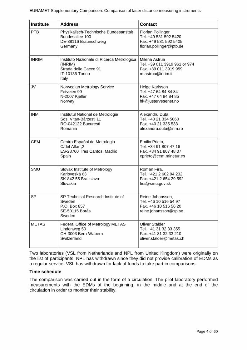
EURAMET Supplementary Comparison Comparison of laser distance measuring instruments
Page 4 of 60
Institute Address Contact
PTB Physikalisch-Technische Bundesanstalt Bundesallee 100 DE-38116 Braunschweig Germany
Florian Pollinger Tel +49 531 592 5420 Fax +49 531 592 5405 florianpollingerptbde
INRIM Instituto Nazionale di Ricerca Metrologica (INRIM) Strada delle Cacce 91 IT-10135 Torino Italy
Milena Astrua Tel +39 011 3919 961 or 974 Fax +39 011 3919 959 mastruainrimit
JV Norwegian Metrology Service Fetveien 99 N-2007 Kjeller Norway
Helge Karlsson Tel +47 64 84 84 84 Fax +47 64 84 84 85 hkjustervesenetno
INM Institutul National de Metrologie Sos Vitan-Bacircrzesti 11 RO-042122 Bucuresti Romania
Alexandru Duta Tel +40 21 334 5060 Fax +40 21 335 533 alexandrudutainmro
CEM Centro Espantildeol de Metrologia Cdel Alfar 2 ES-28760 Tres Cantos Madrid Spain
Emilio Prieto Tel +34 91 807 47 16 Fax +34 91 807 48 07 eprietocemminetures
SMU Slovak Institute of Metrology Karloveskaacute 63 SK-842 55 Bratislava Slovakia
Roman Fiacutera Tel +421 2 602 94 232 Fax +421 2 654 29 592 firasmugovsk
SP SP Technical Research Institute of Sweden PO Box 857 SE-50115 Borarings Sweden
Reine Johansson Tel +46 10 516 54 97 Fax +46 10 516 56 20 reinejohanssonspse
METAS
Federal Office of Metrology METAS Lindenweg 50 CH-3003 Bern-Wabern Switzerland
Oliver Stalder Tel +41 31 32 33 355 Fax +41 31 32 33 210 oliverstaldermetasch
Two laboratories (VSL from Netherlands and NPL from United Kingdom) were originally on the list of participants NPL has withdrawn since they did not provide calibration of EDMs as a regular service VSL has withdrawn for lack of funds to take part in comparisons
Time schedule
The comparison was carried out in the form of a circulation The pilot laboratory performed measurements with the EDMs at the beginning in the middle and at the end of the circulation in order to monitor their stability
EURAMET Supplementary Comparison Comparison of laser distance measuring instruments
Page 5 of 60
Laboratory Country Date
GUM Poland February 2011 MIKES Finland March 2011 SP Sweden April 2011 AS Metrosert Estonia May 2011 PTB Germany June 2011 GUM Poland August-September 2011 CMI Czech Republic October 2011 SMU Slovakia November 2011 INM Romania December 2011 INRIM Italy January 2012 CEM Spain February 2012 BEV Austria April 2012 JV Norway June 2012 METAS Switzerland July 2012 GUM Poland August 2012
Transportation
The transportation of the devices was not critical In most cases courier services were used The ATA carnet issued outside the EU was handled correctly in all cases
3 Description of the standards 4 EDMs of different quality classes were used For each of the two different manufacturers two models of EDMs were selected
Manufacturer type Serial no Dimensions Uncertainty declared Resolution
Bosch DLE 50 782511118 (100x58x32) mm 15 mm 1 mm
Bosch GLM 150 005051241 (120x66x37) mm 1 mm 01 mm
Leica DISTO D3a BT 902520011 (127x49x27) mm 1 mm 01 mm
Leica DISTO D8 500950167 (143x55x30) mm 1 mm 01 mm
Target plate ndash (275x198x3) mm ndash ndash
Technical protocol ndash ndash ndash ndash
Bosch DLE 50 Bosch GLM 150 Leica DISTO D3a BT Leica DISTO D8
EURAMET Supplementary Comparison Comparison of laser distance measuring instruments
Page 6 of 60
4 Handling and measurement instructions Measurement instructions
Before calibration the EDMs were inspected for damage It was checked if their batteries had been discharged If necessary the batteries were replaced with new ones
The Leica DISTO D8 was set to the ldquostandard moderdquo (not ldquolong rangerdquo)
The EDMs were calibrated with beam pointing horizontally and lying up display It was mandatory to use the included target plate (no adhesive tape side no division line area)
Each EDM was calibrated at a distance of 03 m and regularly spaced intervals every 5 m (as close as possible to these points) for the range up to 50 m Laboratories with a maximum range of less than 50 meters performed measurements up to the highest possible measurable multiple of 5 meters
The measurement results were corrected to the reference temperature of 20degC
The measurement results instrument description and a detailed evaluation of the measurement uncertainty were reported using forms given in the protocol All results were transmitted electronically as well as a signed paper report
Measurand
Typically the laser beam is not perpendicular to the back of EDM To achieve laser beam perpendicular to the target plate angular position of the EDM body was corrected
The measurand for this comparison was a distance from the point at the rear of the angularly corrected EDM farthest from the target plate to the target plate (see figure below)
5 Measurement equipment and methods used by the par ticipants The participating laboratories gave a short description in their measurement report related to the equipment and method used for EDMsrsquo calibration These reports are given in Appendix 1 Most of the laboratories used a laser interferometer system for the length measurement others used a reference tape and reference baseline (see table below)
EURAMET Supplementary Comparison Comparison of laser distance measuring instruments
Page 7 of 60
Lab Bench length Reference
GUM 50 m Laser interferometer MIKES 30 m Laser interferometer SP 50 m 50 m steel tape AS Metrosert 20 m Laser interferometer PTB 50 m Laser interferometer CMI 30 m Laser interferometer SMU 40 m 50 m steel tape INM 50 m Laser interferometer INRIM 25 m Laser interferometer CEM 50 m Reference baseline calibrated by total station BEV 50 m Laser interferometer JV 50 m Laser interferometer METAS 50 m Laser interferometer
EU
RA
ME
T S
upplementary C
omparison C
omparison of laser distance m
easuring instruments
P
age 8 of 60
6 M
easurement results
In the tables below the m
easurement results and the expanded m
easurement uncertainties
are given for all laboratories and the four ED
Ms
Table 1 Measurement results for BOSCH DLE 50 EDM and expanded measurement uncertainties (k=2) The results reported by laboratories were corrected to nominal length of the measured distances
Table 2 Measurement results for BOSCH GLM 150 EDM and expanded measurement uncertainties (k=2) The results reported by laboratories were corrected to nominal length of the measured distances
EU
RA
ME
T S
upplementary C
omparison C
omparison of laser distance m
easuring instruments
P
age 9 of 60
Table 3 Measurement results for LEICA D3a and expanded measurement uncertainties (k=2) The results reported by laboratories were corrected to nominal length of the measured distances
Table 4 Measurement results for LEICA D8 and expanded measurement uncertainties (k=2) The results reported by laboratories were corrected to nominal length of the measured distances
EURAMET Supplementary Comparison Comparison of laser distance measuring instruments
Page 10 of 60
7 Measurement uncertainties The participants were asked to report detailed measurements uncertainty budgets evaluated according to the ISO Guide In table 5 the majority of the contributions are summarized as they had been reported by the participants
Tab
le 5
Sum
mar
y of
the
mos
t fr
eque
ntly
rep
orte
d m
easu
rem
ents
unc
erta
inty
con
trib
utio
ns in
mm
tak
en fr
om
unce
rtai
nty
budg
ets
repo
rted
by
the
part
icip
atin
g la
bora
torie
s
EURAMET Supplementary Comparison Comparison of laser distance measuring instruments
Page 11 of 60
8 Stability of the EDMs
Repeatability measurements showed that in the short period (less than 60 min) indications of the EDMs did not reveal any drift Large differences (~ 15 mm) were also noted between the mean values of the subsequent measurement series performed within 48 hours Considering this effect in uncertainty budget and on the basis of measurements made at the beginning in the middle and at the end of the comparison one cannot determine the drift of the results
Stability measurements Bosch DLE 50
-25
-20
-15
-10
-05
00
05
10
15
20
25
03 5 10 15 20 25 30 35 40 45 50
Length m
Dev
iatio
n fro
m m
ean
m
m
2011 02
2011 08
2012 09
Stability measurements Bosch GLM150
-15
-10
-05
00
05
10
15
03 5 10 15 20 25 30 35 40 45 50
Length m
Dev
iatio
n fr
om m
ean
m
m
2011 02
2011 08
2012 09
Stability measurements Leica DISTO D3a BT
-15
-10
-05
00
05
10
15
03 5 10 15 20 25 30 35 40 45 50
Length m
Dev
iatio
n fro
m m
ean
m
m
2011 02
2011 08
2012 09
Stability measurements Leica DISTO D8
-10
-08
-06
-04
-02
00
02
04
06
08
10
03 5 10 15 20 25 30 35 40 45 50
Length m
Dev
iatio
n fro
m m
ean
mm
2011 02
2011 08
2012 09
Fig 1 Measurements of the pilot laboratory monitoring the stability of all four EDMs at each of the measuring distances bounded by the expanded measurements uncertainty (for k=2 dashed line) The solid curves represent deviation from the arithmetic mean of the three measurements The test of the stability of the EDMs showed significant changes in the mean results in timescale months or even days A detailed analysis of the observed problems will be presented by way of example with Leica DISTO D8 and for a 10 m distance This EDM has been chosen because it is theoretically the best of the compared models with resolution of 01 mm over whole range Depending on the measured distance the EDM is characterized by some measurement uncertainty Typically the standard deviation increases along the distance Distance of 10 m was selected to minimize the impact of the uncertainty on a single measurement The more the distance from the target increases the weaker the reflected signal becomes and the more the uncertainty of a single measurement increases while for very short distances the reflected signal is so strong that it can also have a negative impact on the results
Stability over few minutes time interval
The studies performed showed that deviations from expected value are well characterized by normal distribution Results of those studies are presented in the figure below Probability density of deviations from expected value for Leica D8 for 10 m is consistent with a normal
EURAMET Supplementary Comparison Comparison of laser distance measuring instruments
Page 12 of 60
distribution with standard deviation s = 019 (blue marks ndash experimental red line ndash fitted model)
-10 -9 -8 -7 -6 -5 -4 -3 -2 -1 0 1 2 3 4 5 6 7 8 9 10
dx 01 mm
Fig 2 Distribution of results over few minutes time interval
Stability over tens of minutes time interval
Several series of measurements were made with a duration from 15 minutes to 30 minutes at a constant distance and under constant measurement conditions For most of the series changes in the average value of indications of EDMs have been observed at the level of about 02 mm However for one of the series change exceeds 05 mm (see figure below) This value leads to u = 015 mm
-06
-04
-02
0
02
04
06
08
1
0 5 10 15 20 25 30
t min
dx
mm
Fig 3 Stability of results over tens of minutes time interval
Stability in the timescale of days and months
The measurements were performed in three series of measurements over an interval of a few days The cycle of measurements was repeated twice within a few months The first three measuring series were carried out in February 2011 then in August 2011 and the last one in September 2012
In the figure below the standard deviations of individual measurements of distance are shown with error bars The dashed lines represent minimum and maximum values of individual measurements in the series of measurements
EURAMET Supplementary Comparison Comparison of laser distance measuring instruments
Page 13 of 60
Leica DISTO D8 (interval 010 m)
-06
-04
-02
00
02
04
06
08
10
12
14
series
devi
atio
n fro
m n
omin
al le
ngth
m
m
Fig 4 Results of all series of measurements for Leica DISTO D8 for a distance of 10 m
Having analyzed the graph one can see that the maximum and minimum values in each series performed at an interval of several months do not overlap The mean value in one of the series is not even in a range limited by minimum and maximum for the other series
Such a large differences between the average values appear over a time scale longer than few days This means that the laboratory couldnrsquot observe this variability when briefly examining the instrument
In the figure below probability density of all results from all measurement series was presented
-10 -5 0 5 10 15 20
dx 01 mm
Fig 5 Distribution of all results from all measurement series
Continuous red curve represents the sum of the theoretical normal distributions for each series of measurements Theoretical curve is consistent with the observed distribution
max (x1x9)
min(x1x9)
di
201102 201108 201209
EURAMET Supplementary Comparison Comparison of laser distance measuring instruments
Page 14 of 60
Estimation of uncertainty of artifact
The reproducibility of EDM is affected by random changes of mean values in time scale of days To determine di for a given EDM and a given distance the results from all nine series of measurements )( 91 xx were used
)min()max( 9191 xxxxdi minus=
where i is an index of measurement distance
Set of eleven di was determined for each EDM The figure below presents those results
0
05
1
15
2
25
0 5 10 15 20 25 30 35 40 45 50
Length m
d i
mm
DLE 50
GLM 150
D3s BT
Leica D8
Fig 6 di values for all distances for each EDM
The value of di varies widely This is especially noticeable in Bosh DLE 50 where for the neighboring distances the di values can differ by several times Each EDM is characterized by a different trend
The model assumes that long-term stability is characterized by rectangular distribution with domain described by maximal di and expected value estimated based on all of the measurements Dispersion of individual measurements (short-term stability) is described by normal distribution
The max value of di was used to estimate uncertainty u(dart) related to random changes of EDM results In order to disentangle u(dart) one should try to subtract the observed short term stability from max(di) and influences of the different alignments like zero point uzero cosine error ucos and parallelism uparal [3]
( ) 22cos
2
2
art2
32
)max(paralzero
i uuud
du minusminusminus
=
In the case of Leica DISTO D8 we obtain max(di) = 1133 which corresponds to u(dart) = 0324 mm
Table below contains values of u(dart) estimated for all the four EDMs
EURAMET Supplementary Comparison Comparison of laser distance measuring instruments
Page 15 of 60
Table 6 Values of u(dart) for all the four EDMs
EDM u(dart) (mm)
Bosch DLE 50 0308
Bosch GLM 150 0197
Leica DISTO D3a BT 0149
Leica DISTO D8 0324
Additional stability test of EDMs
The suspected main factors responsible for the change of EDMs indications are 1) Effects of electronics ndash resulting from unstable operation of the EDM 2) Effects of mechanics ndash impact of transport of the EDM between laboratories 3) Effects of geometry ndash alignment repeatability of the EDM during measurements
Two additional experiments were conducted in order to determine which factors have the greatest impact on the results Leica DISTO D3a BT was used for these tests
a) Static test
During the measurements the EDM was immobilized on a bench Measurements were made at a distance of 10 m in a controlled environment The measurement results are presented in the figure below
-04
-03
-02
-01
00
01
02
03
04
1 2 3 4 5 6 7 8 9 10 11 12 13 14 15 16 17 18 19 20
measure
dx
mm
Fig 7 Static stability test results
Each point represents the mean value of 15-20 measurements This test covers about 6 hours of EDM work The standard deviation is s = 009 mm
b) Dynamic test
Measurements were made at a distance of 10 m in a controlled environment After each series of measurements the EDM was removed from the bench shaken and squeezed The aim was to simulate the conditions during transportation This test covers about 6 hours of EDM work Measurement results are presented in the figure below
EURAMET Supplementary Comparison Comparison of laser distance measuring instruments
Page 16 of 60
-04
-03
-02
-01
00
01
02
03
04
1 2 3 4 5 6 7 8 9
measure
dx
mm
Fig 8 Dynamic stability test results
The standard deviation for this test is s = 015 mm and is greater than in the static test
The average standard deviation of three measurement series was estimated using the data from the comparison The value s = 009 mm is similar to the result in the static test
The estimated uncertainty associated with the artifact for this EDM is uart = 015 mm (see table above) The same value u = 015 mm was estimated from the stability test in the scale of tens of minutes Both values are close to the value of standard deviation for the dynamic test
These results may lead to the conclusion that the level of the effects of electronics mechanics and geometry have a similar impact on the long-term stability Due to this fact it is difficult to identify which of these factors has the greatest impact on the observed measurement results
EURAMET Supplementary Comparison Comparison of laser distance measuring instruments
Page 17 of 60
9 Reference values The standard approach is to use weighted mean for determining the reference value xref [12] This is calculated by the mean of all measurement values xi weighted by the inverse square of the standard uncertainties u(xi) associated with the measurements and using these values the largest consistent subset of the sample is determined However checking the consistency of the sample without taking into account the uncertainty associated with the artifact leads to erroneous recognition of the consistent subset We propose to add uart to the uncertainty of each laboratory at the beginning of the calculation
( ) )()( 222iartic xuduxu +=
Thereby the uncertainty associated with the artifact will be taken into account during the consistency check
sum
sum
=
==n
i ic
n
i ic
i
ref
xu
xu
x
x
12
12
)(
1
)(
The pilot laboratory contributed only by its first measurements to the reference values The weighted mean approach requires the individual uncertainties from the laboratories to be estimated according to a common approach (as they should be since all participants were requested to estimate the uncertainties according to the ISO Guide) The standard uncertainty u(xref) of the reference value is calculated by combining the individual uncertainties
sum=
=n
i ic
ref
xu
xu
12
2
)(
1
1)(
The χ2 test was applied in order to estimate xref from the largest consistent subset [1]
EURAMET Supplementary Comparison Comparison of laser distance measuring instruments
Page 18 of 60
Table 7 Reference values and associated standard uncertainties based on weighted mean
Distance Bosch DLE 50 Bosch GLM 150 Leica DISTO D3a BT
Leica DISTO D8
mm xref u(xref) xref u(xref) xref u(xref) xref u(xref)
300 299694 0138 300475 0084 300353 0071 300177 0113
5000 4999900 0139 4999774 0090 5000020 0074 4999659 0111
10000 10000041 0146 9999776 0096 10000285 0077 10000336 0114
15000 14999945 0154 14999781 0120 15000176 0080 15000258 0117
20000 19999804 0175 19999423 0124 20000112 0086 20000581 0118
25000 24999955 0186 24999526 0128 25000321 0094 25000754 0124
30000 29999586 0193 29999956 0138 30000140 0103 30000675 0129
35000 34999779 0235 35000051 0156 35000022 0119 35000844 0153
40000 40000185 0279 40000250 0159 40000476 0132 40001167 0151
45000 44999576 0315 45000208 0165 45000391 0155 45000974 0156
50000 49999983 0324 50000344 0169 50000319 0156 50001137 0157
EURAMET Supplementary Comparison Comparison of laser distance measuring instruments
Page 19 of 60
10 Deviations from reference values The following figures show results from NMIs for all of the distances Reference value is represented by a bold black line
Bosch DLE 50
-30
-25
-20
-15
-10
-05
00
05
10
15
20
25
30
0 5 10 15 20 25 30 35 40 45 50 55
Length m
Dev
iatio
n fr
om n
omin
al le
ngth
m
m
MIKES
SP
Metrosert
PTB
CMI
SMU
INM
INRIM
CEM
BEV
JV
METAS
GUM
Ref
Bosch GLM 150
-20
-15
-10
-05
00
05
10
15
20
0 5 10 15 20 25 30 35 40 45 50 55
Length m
Dev
iatio
n fr
om n
omin
al le
ngth
m
m
MIKES
SP
Metrosert
PTB
CMI
SMU
INM
INRIM
CEM
BEV
JV
METAS
GUM
Ref
Fig 9 Deviations from reference values
EURAMET Supplementary Comparison Comparison of laser distance measuring instruments
Page 20 of 60
Leica DISTO D3a BT
-20
-15
-10
-05
00
05
10
15
20
0 5 10 15 20 25 30 35 40 45 50 55
Length m
Dev
iatio
n fr
om n
omin
al le
ngth
m
m
MIKES
SP
Metrosert
PTB
CMI
SMU
INM
INRIM
CEM
BEV
JV
METAS
GUM
Ref
Leica DISTO D8
-20
-15
-10
-05
00
05
10
15
20
0 5 10 15 20 25 30 35 40 45 50 55
Length m
Dev
iatio
n fr
om n
omin
al le
ngth
m
m
MIKES
SP
Metrosert
PTB
CMI
SMU
INM
INRIM
CEM
BEV
JV
METAS
GUM
Ref
Fig 9 Deviations from reference values (continued)
The deviations Di from reference value xref are calculated by
refxxD ii minus=
For calculating the expanded uncertainty of these deviations U(Di) the corresponding uncertainties u(xi) and u(xref) cannot simply be geometrically added because the values xi and xref are correlated Due to the random changes described in section 6 uncertainty u(dart) was added [2] It can be shown that the expanded uncertainty U(Di) is given by
)()()(961)( art2
ref22 duxuxuDU ii +minus=
when xi belongs to the largest consistent subset and
)()()(961)( art2
ref22 duxuxuDU ii ++=
EURAMET Supplementary Comparison Comparison of laser distance measuring instruments
Page 21 of 60
otherwise The deviations from the reference values are given in various figures and tables below The uncertainty bars in the figures correspond to the expanded uncertainties U(Di) (k = 196)
Fig 10 Deviations from reference values
EURAMET Supplementary Comparison Comparison of laser distance measuring instruments
Page 22 of 60
Fig 10 Deviations from reference values (continued)
EURAMET Supplementary Comparison Comparison of laser distance measuring instruments
Page 23 of 60
Fig 10 Deviations from reference values (continued)
EURAMET Supplementary Comparison Comparison of laser distance measuring instruments
Page 24 of 60
Fig 10 Deviations from reference values (continued)
EURAMET Supplementary Comparison Comparison of laser distance measuring instruments
Page 25 of 60
Fig 10 Deviations from reference values (continued)
EURAMET Supplementary Comparison Comparison of laser distance measuring instruments
Page 26 of 60
Fig 10 Deviations from reference values (continued)
EURAMET Supplementary Comparison Comparison of laser distance measuring instruments
Page 27 of 60
Fig 10 Deviations from reference values (continued)
EURAMET Supplementary Comparison Comparison of laser distance measuring instruments
Page 28 of 60
Fig 10 Deviations from reference values (continued)
EU
RA
ME
T S
upplementary C
omparison C
omparison of laser distance m
easuring instruments
P
age 29 of 60
Table 8 Deviations from the reference value (given at the top of the table) and expanded uncertainties (k=196) of such deviations for BOSCH DLE 50
Table 9 Deviations from the reference value (given at the top of the table) and expanded uncertainties (k=196) of such deviations for BOSCH GLM 150
EU
RA
ME
T S
upplementary C
omparison C
omparison of laser distance m
easuring instruments
P
age 30 of 60
Table 10 Deviations from the reference value (given at the top of the table) and expanded uncertainties (k=196) of such deviations for Leica DISTO D3a BT
Table 11 Deviations from the reference value (given at the top of the table) and expanded uncertainties (k=196) of such deviations for Leica DISTO D8
EURAMET Supplementary Comparison Comparison of laser distance measuring instruments
Page 31 of 60
11 En Tables Results with En gt 1 are marked with red color in Tables below En values are calculated by Di U(Di) with Di and U(Di) as given on page 19
Table 12 BOSCH DLE50
Lab Distance (mm) 300 5000 10000 15000 20000 25000 30000 35000 40000 45000 50000
MIKES -058 017 -019 -023 035 -002 -096 SP 020 019 006 005 009 059 064 037 028 097 001
Metrosert -030 -031 -003 018 032 PTB 001 029 022 -006 011 -036 001 -023 -075 -083 001 GUM -033 -005 -018 -009 000 006 017 005 -026 -028 019 CMI -003 020 -009 004 005 -022 028 SMU 006 -049 -034 -023 -017 -057 051 039 021 INM 032 031 037 006 020 005 -079 -119 -272 -260 -269
INRIM 025 -013 000 096 CEM -032 -022 -041 -039 -004 -038 080 001 -094 -047 BEV -010 007 000 -001 008 -011 037 013 -001 008 -001 JV -019 -016 025 -055 055 060 068 163 122 060 089
METAS 038 012 -005 007 -107 004 -024 002 -070 037 -052
Table 13 BOSCH GLM150
Lab Distance (mm) 300 5000 10000 15000 20000 25000 30000 35000 40000 45000 50000
MIKES 005 -002 019 018 027 019 062 SP 003 068 029 023 051 008 015 016 -005 -001 038
Metrosert -061 -011 -022 -021 -003 PTB 066 074 062 062 034 053 047 048 047 091 064 GUM -007 -014 007 -018 000 023 020 033 014 032 038 CMI -057 -032 -030 -064 -050 -047 000 SMU 023 -024 -060 012 062 001 -003 050 047 INM -022 017 -003 002 -003 054 005 -006 016 -022 -055
INRIM 079 -052 -050 -026 -034 -042 CEM 002 002 -034 -020 -029 -077 -077 -077 -074 -104 BEV -004 -002 -007 010 -042 -042 -029 -011 -028 -022 -030 JV 003 015 040 011 -020 021 -029 -005 028 036 058
METAS -047 -020 005 002 -012 -033 -054 -065 -053 -082 -040
Table 14 Leica DISTO D3a BT
Lab Distance (mm) 300 5000 10000 15000 20000 25000 30000 35000 40000 45000 50000
MIKES 008 094 050 -011 028 051 045 SP 033 038 056 017 053 065 076 051 017 071 011
Metrosert -060 -004 -037 -014 -002 PTB 067 000 070 030 089 062 061 081 124 050 072 GUM 023 019 035 008 038 053 029 058 070 064 063 CMI -001 -004 027 -011 011 034 -033 SMU 002 -013 -019 007 -013 -055 045 -013 -042 INM 002 -039 -058 001 002 -045 -080 -051 -102 -101 -378
INRIM 070 -020 063 101 CEM -028 -004 -004 -064 003 -002 -050 -022 -093 -160 BEV -032 -019 -019 004 -011 -037 -017 -002 -025 005 012 JV 027 019 027 042 046 039 043 048 072 115 024
METAS -091 -008 -102 -098 -111 -103 -092 -080 -073 -108 -043
EURAMET Supplementary Comparison Comparison of laser distance measuring instruments
Page 32 of 60
Table 15 Leica DISTO D8
Lab Distance (mm) 300 5000 10000 15000 20000 25000 30000 35000 40000 45000 50000
MIKES 025 013 058 036 038 061 022 SP 057 026 040 016 013 016 025 017 -007 -019 007
Metrosert -021 006 -016 -043 -019 PTB 040 011 035 -005 -011 -002 -004 035 047 022 069 GUM -028 005 -025 031 039 -015 029 048 041 052 072 CMI -104 -026 -072 -057 -006 -017 -015 SMU -067 -017 -051 -026 -016 -054 -004 -001 -016 INM 021 -014 009 003 -017 -031 -010 007 029 036 041
INRIM 076 -024 -004 047 -007 083 CEM 004 -009 002 -033 -051 -059 -097 -077 -116 -134 BEV -057 -014 -051 -093 -024 -027 -021 -036 -038 -028 -041 JV 014 031 047 030 044 043 035 056 093 108 030
METAS 035 007 026 038 -013 -024 -011 -048 -089 -074 -066
12 Conclusions It was the first comparison of EDMs For most of the laboratories it was an important opportunity to validate their measurement instrumentation and procedure It allowed to become aware of potential problems and to take corrective actions in changing the procedure
For the evaluation of the reference value the weighted mean approach has been chosen although the consistency check according to procedure A of Ref [1] failed in many cases A more complicated procedure for the evaluation of the reference value was proposed which slightly changes the uncertainty of the reference value
In total there were 23 En values larger than 1 This represents 47 of the full set of 482 results It is less than the 5 of possible values being out of the expanded uncertainty of the reference value for k=2
The uncertainty of the results mainly comes from the uncertainty of the reproducibility It is difficult to distinguish between Labrsquos calibration and measurement capability
The comparison shows a global compliance with declared CMCs independently of whether some participant can have a high percentage of values not compliant with its CMC due to the influence of the artifact and the estimation of its uncertainty
13 References [1] M G Cox The evaluation of key comparison data Metrologia 39 589 ndash 595 (2002)
[2] R Thalmann EUROMET 677 ndash Steel Tape Measures Final report (2004)
[3] F Pollinger personal communication
EURAMET Supplementary Comparison Comparison of laser distance measuring instruments
Page 33 of 60
Appendix 1 Description of the measurement equipmen t as reported by the laboratories
A11 MIKES Finland
Short description of measurement bench
MIKES interferometric bench is situated in an underground laboratory with air temperature and humidity control Typically air temperature is 20 plusmn 01 degC and humidity 45 plusmn 2 RH The linear guide on the top of the concrete beam comprises two parallel round shafts with adjustable fixtures every 1 m A carriage with ball bush bearings is moved along the rail and location of it is measured with reference interferometer HP-5529A Temperature of air is measured with 6 pt100 sensors and Keithley 2010 multimetre with 4-wire resistance mode Air pressure and humidity are measured with Vaisala PTU200 Updated Edleacuten equation by Boumlnsch amp Potulski is used for calculation of refractive index of air
For EDM calibration on the other end than laser interferometer is a fixed reference plate which is adjusted perpendicular to the laser beam Next to the reference plate is an adjustable base for EDM instrument with which it can be adjusted to point parallel and coincident with measurement arm of the interferometer A target plate adjusted perpendicular to laser beam is fixed to the carriage The calibration followed Abbe principle with some millimetre uncertainty in offset adjustment
First reference interferometer is set to zero when the target plate and reference plate are in contact then EDM is positioned and adjusted in its base The rear surface of the EDM is also slightly pressed against reference surface behind it Then the readings from both instruments are collected at selected locations For this calibration there is no fine adjustment of the target position so there are typically deviations of up to few millimetres from nominal locations Results are averages of 3-4 measurements
Additional remarks
The CMC entry MIKES has for EDM calibrations is based on calibration of length scales of high quality total stations and laser trackers This type of EDMs used in this comparison are not accurate enough for truly testing of MIKES calibration measurement capability
EURAMET Supplementary Comparison Comparison of laser distance measuring instruments
Page 34 of 60
A12 SP Sweden
Short description of measurement bench
The bench consists of a simple aluminium Uminusshaped profile with polished steel pins acting as supports for the tape The bench is a little over 50 m long and works as support for the reference tape and the calibrated EDMs simultaneously
Length measurement instrument
Comparison with reference steel tape
Temperature measurement system number and location of sensors
The tape temperature is continuously registered in 6 points equally distributed along the bench The air temperature is monitored during the measurements but not used for corrections
Additional remarks
The EDM support is placed approximately 2 cm vertically above the tape No visual aid is used
EURAMET Supplementary Comparison Comparison of laser distance measuring instruments
Page 35 of 60
A13 AS Metrosert Estonia
Short description of measurement bench
The 21-m bench is located in the designated corridor-like laboratory room The lab is air-conditioned and the stability of temperature is typically plusmn05 ordmC There are three humidity and temperature sensors in room for stability and gradient monitoring
Two stainless steel rails running in parallel are made of 3-m long rods The rails lay without fixed attachment on metal supports which are mounted on concrete base The base rests on pillars made of bricks
Length measurement instrument
Laser-interferometer system Renishaw ML10 was used as length measurement instrument
Laser interferometer gets temperature humidity and pressure data from itrsquos own measurement system EC10
Additional remarks
Due to the length of the bench only measurements up to 20 m could be made Five measurement series were made with each EDM
EURAMET Supplementary Comparison Comparison of laser distance measuring instruments
Page 36 of 60
A14 PTB Germany
Short description of measurement bench
The measurements were performed on the 50 m geodetic base of the PTB The comparator consists of a 50 m rail The laboratory is equipped with a network of 21 temperature sensors spaced by 25 m along the bench As depicted in fig 1 the EDM is mounted at one end of the comparator the reflector is fixed vertically on the carriage A large retroreflector is mounted approximately 150 mm below the EDM reflector on the carriage reflecting the beam of the reference interferometer The deviation of the length due to tilting carriage (Abbe error) has been investigated along the bench by comparison of two interferometers It remains smaller than 100 microm The distance of the first position of 300 mm with respect to the back side of the EDM is determined by a gauge block of 300 mm length and a thickness of 10 mm This procedure is depicted for one of the comparison standards in figure 2
For the calibration the desired positions are programmed After the carriage reaches a measurement position the operator waits for another 30 s for the carriage to settle In control experiments the remaining movement between positioning and measurement remained smaller than 2 microm The operator then activates the measurement of the EDM reads the indicated position and writes it down The procedure is repeated for twelve times at every position the mean of the 12 measurements represents the ldquoindicated distance by the EDMrdquo All measurements of a single run at one position are performed within approximately one minute The complete measurement was repeated for four times
Length measurement instrument
The reference length is determined by a frequency-calibrated laser interferometer (Agilent 5519A) The reference interferometer is set up in Michelson geometry the signals being digitalised by a Heidenhain IK 121 card The index of refraction is determined by the external weather station of the geodetic base consisting of 21 Pt-100 temperature sensors spaced 25 m along the bench two humidity sensors (Testo 650) and two pressure sensors (Setra 370 and DPI 141) The environmental parameters are used to determine the index of refraction for the reference measurement deploying the modification of the Edleacuten equation by Boumlnsch and Potulski
EURAMET Supplementary Comparison Comparison of laser distance measuring instruments
Page 37 of 60
A15 CMI Czech Republic
Description of measurement bench
The EDMs were measured on 30 m long measuring bench equipped by laser interferometer (LI) Renishaw ML10 (pic 1 and 2) calibrated traceable to national standard of length and quantities of environmental sensors The target plate and retroreflector of the LI were fixed on a moving part of the bench and each EDM was fixed in horizontal position by clamps (pic 3) LI and EDM are placed on opposite ends of bench the Abbe offset was lt10 mm for some of them and lt50mm for all The value of LI was reset (to zero) at position corresponding to the rear of the EDM (using 3D measuring arm FARO Quantum with uncertainty about 27microm) The perpendicularities of the EDM stop as well as target plate to the beam were also checked by FARO) Each EDM was 3x replaced and aligned the measurement (reading) was repeated 6 times for each alignment and position the mean value of these 3x6 measurements is stated in tables with results The uncertainty claimed covers the statistical uncertainty of single readings Only in case of Leica D8 (the best performing EDM in this comparison) we state also the uncertainty corresponding to the mean of 6 readings in last column (this uncertainty is smaller and better illustrates our CMC)
Length measurement instrument
- Laser interferometer Renishaw - Laser 633 nm Type ML10 - Compensator EC10 - 3D measuring arm FARO Quantum - 3D measuring arm FARO Quantum
EURAMET Supplementary Comparison Comparison of laser distance measuring instruments
Page 38 of 60
A16 SMU Slovakia
Short description of measurement bench
No bench is available at the SMU the measurements are being carried out in the underground corridor of the laboratory building with length of 428 m
The 50 m steel measuring tape KINEX was used as the reference laid on the floor and pulled by the force 50 N (the same force as had been applied during its calibration at the SMU) The calibration of reference tape was done at the SMU using ULM3m Zeiss with laser interferometer Agilent 5529 B (ie per 3 m parts)
Three mercury thermometers with the resolution of 01 degC were used along the measurement path each of them laid onto the tape and located at 667 m 1990 m (instead of 20 m because of this was one of measuring points) and 333 m respectively Each of them thus corresponded approximately to one third of the measured steel tape section
Regarding the 03 m measuring point the ULM3m Zeiss length measuring machine was used with the 300 mm gauge block as the reference
Length measurement instrument
We used our own target plate being fixed perpendicularly (within uncertainty stated) to the construction equipped with nonius and the camera holder transported manually along the steel tape The second construction was fixed to the tape by such a way that zero line of the tape corresponded to the rear of EDM (within uncertainty stated)
The position of the target is read on the monitor and 20 repeated readings of the EDM data took place in each measuring point (multiples of 5 m up to 40 m)
Concerning 03 m the 300 mm gauge block was fit between the target plate and the construction with EDM The distance of the EDM rear from the target plate corresponded to the length of gauge block (within uncertainty stated)
Additional remarks
The identical measurement method was used as we use to do within our calibration service although the results reporting is different ndash we provide the regression line calculated from the measurement of irregularly distributed points and corresponding uncertainty (k = 2) in the form of [a bL] mm (ie the same coefficients for each length in the range (0 ndash 42) m)
SMU hasnrsquot got this category in CMC tables
EURAMET Supplementary Comparison Comparison of laser distance measuring instruments
Page 39 of 60
A17 INM Romania
Short description of measurement bench
Geodesic base located in the basement of the laboratory with nominal length equal to 50 m having a mobile carriage thet support both laser He-Ne retroreflector and the target of the laser distance measuring instrument in the front of geodesic base exists a support where are aligned both laser interferometer and the laser distance measuring instruments
Length measurement instrument
Laser interferometer type Hewlett Packard model 5526 A with nominal length equal to 50 m resolution 0001 mm
U = 02 microm +0510-6L
Additional remarks
During the measurements the maximum gradient of temperature was equal to 05 degC
EURAMET Supplementary Comparison Comparison of laser distance measuring instruments
Page 40 of 60
A18 INRIM Italy
Short description of measurement bench
The facility for long distance measurements is located in a corridor of the gallery devoted to dimensional metrology The structure consists in a 28 m long rail fixed to a series of pillars which rest directly on the ground released from the vibrations of floor and wall The measuring system is based on a heterodyne interferometer whose mobile arm consists of a hollow retro-reflector mounted on a structure that can run along the rail so-called carriage A photograph of the facility is presented in Fig1
The carriage is moved by a micro-step motor the motor driver receives a digital pulse and converts it into an electrical pulse to run the motor Each pulse causes a rotation of the motor shaft of one step which amounts to 11000 of a complete revolution of the shaft If the pulse frequency increases the rotation becomes continuous with a speed that is directly proportional to the pulse frequency The speed ranges between few microms up to 27 ms with a resolution of 03 microms
Since the carriage must move back and forth automatically for a distance of almost 30 m a remote control to send pulses to the motor driver was implemented It consists of two parts a radio command which allows to set some general parameters of the carriage movement such as the movement direction and mode of travel (slow or fast) and a fast command which is performed by an amplitude modulated laser beam placed at the beginning of the track oriented towards the carriage A photo detector placed above the carriage receives the modulated laser beam which is transformed into pulses to be sent to the driver of the motor The modulation of the laser beam is implemented by a LabView program that controls a digital output of the data acquisition device
Length measurement instrument
The length measurement instrument is based on a heterodyne incremental interferometer The main beam of the interferometer with frequency f1 is generated by a frequency stabilized
EURAMET Supplementary Comparison Comparison of laser distance measuring instruments
Page 41 of 60
He-Ne laser calibrated with respect to the INRIM length standard and sent to the measurement arm the second beam is a portion of the first one diffracted by an acousto-optic modulator (AOM) with frequency f2 = f1 + 80 MHz The reference detector acquires the beat note signal at 80 MHz while the measurement detector acquires a signal at 80 MHz whose phase is varied due to the displacement of the retro-reflector moving on the rail In figure 2 the optical design of the interferometer is presented
Two different measuring techniques have been implemented
1 the ldquophase measuringrdquo technique based on fringes counting with a relative uncertainty of 5middot10-7 but limited at the maximum carriage speed of 3 cms
2 the ldquoDoppler frequency measurementrdquo technique for higher carriage speed based on the measurement of the Doppler frequency shift while the carriage runs
The second technique was validated by means of the comparison with the first technique at low speed with an agreement of the order of 3middot10-6 hence the Doppler frequency method could be considered validated within 01 mm over the whole rail path with the advantage of reducing the time needed to cover long distances so it was used for the EDM comparison
In order to obtain the distance covered by the carriage according to technique 2 the Doppler frequency is measured by a commercial high-performance counter (a Pendulum CNT-90) without dead time based on time stamping then it is converted in speed and integrated over time according to the following formula
( ) ( )int minus=minus= tffn
dtn
ffdairair
λλ
2
1
2
1
where d is the distance covered by the carriage f is the frequency of the measuring signal with the carriage at rest frsquo the frequency of the measuring signal with the carriage moving λi
is the wavelength of the laser in vacuum n - air is the air refractive index and ti is the integration time The difference frsquo-f is just the Doppler frequency due to the moving carriage
The time interval measurement resolution of the instrument is 100 ps and the time base is
EURAMET Supplementary Comparison Comparison of laser distance measuring instruments
Page 42 of 60
connected to the INRIM UTC so that the measurements of the Doppler frequency and the integration time are extremely accurate The environmental parameters such as air temperature atmospheric pressure partial pressure of water were monitored during the measurement process in order to calculate the value of air refractive index according to the Edlenrsquos formula
Comparison set-up
The different technical solutions adopted for the EDMs and for the target plate positioning are discussed in this paragraph and sketched in figure 3
Fig 3 picture of the EDM and target positioning area
Target plate positioning
In order to use the provided target plate an ad-hoc mounting was manufactured at INRIM it consists in a sort of picture frame made in aluminum which slightly clamps the target folded in half and gives it the necessary stiffness to be a reproducible target The upper part of the frame is L-shaped and allows it to be fixed to the carriage structure by means of two screws The rear part of the target mounting is depicted in figure 4 The target mounting was considered necessary because of the poor stiffness and planarity of the plastic target With the aluminium frame a planarity better than 01 mm was guaranteed The target plate is placed few centimetres next to the retro-reflector and normal to the interferometer beam axis since the EDM laser should be as close and parallel as possible to the reference beam
EURAMET Supplementary Comparison Comparison of laser distance measuring instruments
Page 43 of 60
Fig 4 picture of the rear part of the target plate mounting
EDMsrsquo positioning
The EDMs are placed on a cradle-like platform which is able to adjust the inclination of the EDM along the longitudinal axis (pitch angle) The platform height allows the EDMs to be at approx the same height as the interferometer beam A crucial role was played by the stop-wall placed behind the platform since it represents the ldquozero pointrdquo for all the length measurement Hence a particular effort was devoted to align the stop-wall so that it was normal to the interferometer beam axis and parallel to the target plate
Fig 5 detail of EDMsrsquo positioning the cradle-like platform and the stop-wall are well visible
EURAMET Supplementary Comparison Comparison of laser distance measuring instruments
Page 44 of 60
Target and stop-wall alignment
In order to have the stop-wall parallel to the target plate and normal to the interferometer beam axis the following procedure has been used
1) the stop-wall and the target plate were roughly placed trying to set them parallel and normal to the rail by eye (ie within few millimeters)
2) in order to check if the target was normal to the rail one EDM was positioned on the platform the pitch and yaw angles of the EDM were adjusted by observing the position of the EDM laser spot on the target plate when the target is moved along the rail fixed position means laser beam parallel to the carriage movement Then the target was moved until the end of the rail and a thin mirror was kept in contact with it hence observing the EDM laser reflected by the mirror it was possible to adjust the target tilt acting on the screws until the laser beam is reflected back to the source
3) finally in order to check the parallelism between the stop-wall and the target a tool made by a laser pointing orthogonally to its base was used the base was leant against the stop-wall and the laser was centered on the target when the target is near then the target was moved until the end of the rail hence observing the spot of the laser on the target it was possible to adjust the stop-wall orientation
The residual misalignment errors which we were not able to eliminate were kept into account in the uncertainty budget
Measurement of the first 30 cm
Due to the geometry of our set-up it was not possible to perform the first point of measurement by means of the interferometer indeed the carriage (hence the target) is not able to go in contact with the stop-wall
Fig 6 measurement of the first 30 cm the ruler touching the stop-wall and the target and the mechanical probe (in the back) touching the carriage are visible
EURAMET Supplementary Comparison Comparison of laser distance measuring instruments
Page 45 of 60
So a ruler made of aluminum with rounded ends and nominal length equal to 30 cm was adopted to set the distance between the target plate and the stop-wall for the first point of measurement as it is shown in figure 6 The ruler whose length was measured by a CMM machine was inserted between the target and the stop-wall leaning against the latter and the carriage was carefully moved towards the stop-wall until the target lightly touched the ruler A mechanical probe that touches the carriage structure when carriage is in the ldquo30 cmrdquo position was used as a reference measurement to check the repeatability of this distance after each measurement set
Fig 7 detail of the mechanical probe touching the carriage
Environmental parameters
The environmental parameters such as air temperature atmospheric pressure and humidity were monitored during the whole measurement process in order to calculate the value of air refractive index according to the Edlenrsquos formula
Among these parameters the temperature distribution along the mobile arm of the interferometer was our main concern mainly for two reasons
1 the temperature control of the gallery was not perfectly working during the measurement period so temperature drifts had to be monitored
2 longitudinal temperature gradients due to non uniform heating and to the presence of electronic instruments were pretty high
To the purpose 14 thermometers were uniformly dislocated along the rail and automatically recorded for all the measurement period Both temporal drifts and gradients along the path have been taken in account in the uncertainty budget In any case maximum temperature differences along the rail are within 1 degC In fig 8 an extract from the acquisition file is shown
Unfortunately the air conditioning system did not work well during the measurement campaign hence the measurements were performed at a mean temperature of 209 degC
EURAMET Supplementary Comparison Comparison of laser distance measuring instruments
Page 46 of 60
Fig 8 each curve represents the temperature distribution along the rail during the measurements campaign
Carriage waving
Since the rail is not perfectly straight and the measurement laser is not coincident with the measurement beam the Abbegrave error due to waving of the target must be considered A quantitative measurement and a qualitative measurement were carried out With an electronic level placed on the carriage the straightness on the vertical plane has been mapped with a half meter resolution (the data are reported in fig 9) With a laser placed on the carriage the horizontal and vertical waving are qualitatively compared by looking at the movements of the light spot on a target fixed to the rail end As a conclusion the horizontal and vertical waving are comparable in magnitude and the peak to peak error is of the order of 300 arcseconds
Fig 9 vertical waving of the target measured by an electronic level placed on the carriage
EURAMET Supplementary Comparison Comparison of laser distance measuring instruments
Page 47 of 60
Measurement procedure
The measurements were carried out according to the following procedure
The target was set in the starting position with the procedure described above
In sequence the four EDMs are positioned on the base the horizontal and vertical tilt are adjusted and the distance measurement is recorded An additional fifth EDM (Bosh DLE 150 property of INRiM) was included in the measurement sequence Each EDM is placed on the base and gently pushed against the reference wall in such a way that the measurement laser beam starting point is the same for all EDMs Than the horizontal and vertical angles were adjusted in order to hit the central point of the target indicated with two black marks (see pictures 3 and 6) with ldquovisualrdquo alignment The measurement button is then pressed several times (typically 5) and the average reading is recorded Typical dispersion between readings is within few last digit units In case the dispersion between readings is too large the anomaly is recorded
The carriage was then moved in the next position (about 5 m) and the measurement sequence was repeated for the 5 EDMs The operation is repeated up to 25 m The 25 m measurement is than repeated again as well as all the points till the first one so that each point is measured twice each set Since the carriage movement is ldquoopen looprdquo the positioning of the carriage was not exactly in the nominal 5 m intervals For each positioning the incremental displacement is measured by the interferometer in the Doppler mode Finally the measured values were averaged in order to give a single value for each nominal position
At the end of the measurement set when the carriage is at the 30 cm position again the sum of the interferometric measurements should be very close to zero The residual value is compared with the difference between the first and the final measurements of the mechanical probe The difference must be within the uncertainty of the Doppler technique otherwise some error occurred in the measurement set that must be repeated
At the end of the session 10 complete sets of measurements recorded from the 20th to the 30th of January 2012 have been considered for this report
Additional remarks
Effect of laser pointing
During a preliminary set of measurements we noticed a strong and unexpected dependence of the measurement result on the position of the laser spot on the target Indeed since no particular instructions were given about the relative position of the laser spot on target position (except to exclude the central joint between the two halves) we decided to work relatively close to the right side of the target -closer to the interferometer beam- in order to reduce the Abbegrave error We noticed very large errors at large distances in particular of the Leica DISTO D3a (see figure 10)
EURAMET Supplementary Comparison Comparison of laser distance measuring instruments
Page 48 of 60
Fig 10 errors of each EDM In a preliminary set of measurements
We also noticed that this error was strongly dependent on the position of the spot on the target For this reason we carried out a set of measurements at the maximum length in different positions of the target from one edge to the other according to figure 11 The results are reported in table V
EDM A B C D E
Leica D3a -4 +1 0 +24 +43
+2 0 +42 +40
-1 0 +38
Leica D8 0 0 0 2 +7
0 +12 +23
table V deviations (in mm) from the length measured at point C aiming the laser spot at different positions of the target (notations as in figure 11)
We tried to find an explanation to this effect in the shape of the laser spot if the spot was
EURAMET Supplementary Comparison Comparison of laser distance measuring instruments
Page 49 of 60
particularly defocused or had high diffraction some of the energy could fall out of the target and affect the measurement result In fact the images of the spots (shown in fig 12) do not support this hypothesis Finally we decided to use the center of the (half) target for the comparison
Changing the target
In order to investigate the influence of the target on the measurements a cardboard foil (400 x 400) mm was fixed to the target mounting and a complete set of measurements was performed The results reported in figure 13 and 14 do not show any evidence of a possible dependency of the EDM measurement on the target kind
EURAMET Supplementary Comparison Comparison of laser distance measuring instruments
Page 50 of 60
Measurement at 50 m
Although we are not able to perform traceable length measurements beyond 28 m we wanted to get a sense of EDMs behaviour at longer distances So a target (represented by a rack side wall) was placed at approximately 50 m one after the other the EDMrsquos were positioned on the base and pointed towards the target The measurements were repeated then the target was replaced by the target used for the comparison and a third set of measurements were performed To our great surprise all the EDMrsquos were in good agreement (within 2 or 3 mm for each set of measurement) even those which showed errors of the order of five to ten millimeters at 25 m namely BOSCH DLE 50 and LEICA DISTO D3a Therefore each set of measurements was averaged and the deviations from the mean value are reported in figure 15
EURAMET Supplementary Comparison Comparison of laser distance measuring instruments
Page 51 of 60
Fig 15 Deviations from average value of the measurements At 50 m
EURAMET Supplementary Comparison Comparison of laser distance measuring instruments
Page 52 of 60
A19 CEM Spain
Short description of the measurement bench
To make the measurements of EDMs we have used a reference line made of adjustable supports fixed on a wall of the laboratory Each support is nominally separated five metres from the previous one so we can generate reference lengths up to fifty metres with a pitch of five metres The supports are designed to accommodate both targets and handheld EDMs Distances between supports were measured by using a total station traced to national standards The relative angles of the bases have been measured and corrected
Fig 1 - View of three consecutive supports of the 50 m baseline (left) Lab technician situating an EDM on the first support of the baseline (right)
Length measurement instrument
The baseline was calibrated by using a total station Leica TDA5005 with spherical reflector the calibration uncertainty being 02 mm for k = 2
The target is provided by the comparison The quality of the target was judged as not good due to geometrical constructive errors and the lack of rigidity and stability We measured the flatness of the target surface the distance edge-surface and the angle between them by using a 3D coordinate measuring machine The results of flatness and angle were included in the uncertainty budget and the distance EDM-target was corrected for each EDM due to each beam impinged on a different point of the target
We were not able to measure the distance 0 to 03 m because the baseline pitch is 5 meters and although we are able to measure shorter values in a different facility the target was not appropriate for our bench
EURAMET Supplementary Comparison Comparison of laser distance measuring instruments
Page 53 of 60
Fig 2 - View of an EDM on the first support of the baseline (left) A closer look showing the support adjustments and the origin plate (right)
Fig 3 - View of the comparison target on one of the supports of the baseline (left) A closer look showing the target edge against the support rigid reference (right)
Measurement method
The measurements were carried out by comparison against the known values of the calibrated baseline (metallic references on supports)
Environmental conditions were maintained within the following limits
- Temperature 20 ordmC plusmn 05 ordmC
- Humidity 45 plusmn 10
Each laser distance measuring instrument was placed at the first support of the base and aligned so that the laser beam was perpendicular to the target as indicated by the comparison protocol
For each measurement we took the average of thirty measurements It permitted us to evaluate the repeatability of the instrument
EURAMET Supplementary Comparison Comparison of laser distance measuring instruments
Page 54 of 60
A110 BEV Austria
Short description of the measurement bench
Fig 1 Carriage of tape bench View from the laser interferometer side Retroreflector mounted on the vertical plate the EDM target is mounted on the backside
Fig 2 Support for the DUT Adjustable with 2 translational and 2 rotational degrees of freedom respectively
Fig 3 Setting of the 300 mm starting position Note the rough-and-ready mounted target plate
Fig 4 Laser interferometer side of the bench The DUT is 50 m away on the other side
EURAMET Supplementary Comparison Comparison of laser distance measuring instruments
Page 55 of 60
Measurement procedure 1 The EDM is positioned with the help of a 4-axis positioning stage so that its laser beam is
coaxial with the measurement direction of the laser interferometer (in head on configuration)
2 The EDM is removed from its support The bench carriage is positioned so that the distance of the target plate from the EDM back support is 300 mm A length bar with spherical faces is used for this adjustment The laser interferometer is preset to 300 mm and the EDM is put back on its support
3 At each position 10 consecutive measurements are taken (repeatability) and the carriage is moved to the next position The carriage is manually moved under control of the laser interferometer until it is within plusmn30 microm at the correct position (Exception for the DLE 150 the target is not positioned at 10 m but at 10 m ndash 1 mm to make use of the higher resolution) The indicated (not the nominal) distance of the laser interferometer is recorded for the determination of the deviation
4 After reaching the 50 m position all points are measured in reverse order (bidirectional) Immediately after the last measurement the EDM is removed and the indication using the 300 mm length bar is checked (thus noting a possible drift of the setup)
5 Each instrument was measured 4 times according to this procedure on different days (reproducibility of bench and instrument)
Length measurement instrument
Agilent laser interferometer with long range option The bench was completed short time before performing these measurement So the characterisation was not complete and the respective measurement uncertainty of the laser interferometer is estimated rather high But anyway its contribution to the overall uncertainty can nearly be neglected
Additional remarks
The uncertainty originating from the DUT is the dominating uncertainty contribution Specifically the resolution of the two Bosch instruments (1 mm) and the repeatability are the largest contributions For the DLA 50 the pooled standard deviation of a reading at 50 m is larger than 2 mm Moreover the length dependence is not a simple function
All of the instruments show a significant deviation of the laser beam from the normal of the back (reference) face of the instrument The measured angles reach from 04deg (D3a) to 11deg (DLE 50) This leads depending on the outer dimensions of the instruments to a constant uncertainty contribution of 02 mm in our setup It must be noted that the reference faces are not well defined in most of the instruments
The reproducibility is quite different for the four instruments so only part of it originates from the setup For CMC claims we will use the standard uncertainty value of the most reproducible instrument (D3a) which amounts to 013 mm For an ideal instrument with a resolution of 01 mm and perfect repeatability we would thus have a constant expanded uncertainty of 053 mm up to 50 m
EURAMET Supplementary Comparison Comparison of laser distance measuring instruments
Page 56 of 60
A111 JV Norway
Short description of measurement bench
EDM under calibration and the reference system are aligned along a 50 m measurement bench with rails to carry the linear movement of a target plate for the EDM and a corner cube reflector for the reference system The distance between parallel axis of EDM and axis of the reference system is 130 mm Abbe error due to angle errors for the movement is smaller than 01 mm and is corrected for at each measurement point At long lengths an aperture is used approximately midway between the target plate and the EDM to avoid interfering stray light to the EDM
Alignment procedure
1) Alignment of reference system to the movement of the carriage (rails)
2) Alignment of the EDM to the movement of the carriage (rails)
3) Alignment of a plane mirror at the position of the target plate using back-reflection to the EDM output (normal incident of light on the mirror)
4) Take out the EDM and align the zero reference plate at the back of the EDM to the plane mirror
5) The mirror is replaced by the target plate and the target plate is aligned to the zero reference plate
6) Zero setting of the reference measurement system when target plate is at zero distance to the reference plate at the back of the EDM
7) Put the EDM back in position and realign it to the movement of the carriage (rails)
8) Zero setting of the EDM to the reference plate
Image 1) Image 2) Image 3) Image 4)
Image 1) Items 5) ndash 6) in alignment procedure
Fixture for HP linear interferometer is seen bottom right Part of Wyler instrument is seen to the left blue colour
Image 2) Items 7) and 8) in alignment procedure
Micrometer screws for angle alignment in two directions and linear translation for zero setting of the EDM Push button on the EDM is positioned at the tilting point of the angle adjustment table to maximize stability during measurement HP 5519 A laser head is seen to the right
Image 3) Ready to measure at selected distances from zero point the reference plate
Image 4) EDM spot size at 50 m
Length measurement instrument
- Hewlett Packard Dynamic Calibrator 5519 A (max range 80 m)
- Pressure air temperature humidity Vaisala
EURAMET Supplementary Comparison Comparison of laser distance measuring instruments
Page 57 of 60
- Digital high resolution angle measurement Wyler
I used our own target plate which is of the same type as enclosed in the artefact suitcase article number 766560 from Leica but with reduced size width x hight = 90 x 137 mm
The zero reference plate is of similar type and size
Before measurements batteries of EDMs were switched to new batteries Old batteries are switched back after calibration
For L gt 5 m an aperture of similar size as the target plate is used approximately midway between the EDM and the target plate
Additional remarks
Reports on EDM indicated values at each measurement point is the average value of n = 5 repetitions A linear model of the standard deviation for the repeatability of the EDM readings at different lengths is estimated using m = 20 repetitions at least 5 positions along the scale An estimate of the length dependent repeatability is made for each instrument
The expanded uncertainty U(95) is rounded up to the limiting resolution of 1 mm in the interval 10 m to 40 m for Bosch GLM 150
After the calibration we also estimated the angle error of the optical axis of the EDM to its back plane (back reference of EDM) Bosch DLE 50 26 mrad up measured at 50 m Bosch GLM 150 8 mrad to the left measured at 50 m Leica DISTO D3a 37 mrad down measured at 20 m Leica DISTO D8 2 mrad to the left and 4 mrad down (45 mrad total) measured at 20 m
The distance between parallel walls will be measured too large if the back plane is assumed to be normal to the optical axis of the EDM by ∆LL = (1cosα ndash 1) Bosch DLE 50 ∆LL = 340 ppm (∆L = 17 mm at L = 50 m) Bosch GLM 150 ∆LL = 32 ppm (∆L = 16 mm at L = 50 m) Leica DISTO D3a ∆LL = 7 ppm (∆L = 034 mm at L = 50 m) Leica DISTO D8 ∆LL = 10 ppm (∆L = 05 mm at L = 50 m)
EURAMET Supplementary Comparison Comparison of laser distance measuring instruments
Page 58 of 60
A112 METAS Switzerland
Short description of measurement bench (photo recom mended)
50 m bench with laser interferometer (see photo detailed description in Michel Degoumois Un Long laboratoire de mesure OFMETinfo Vol5 No 2 1998)
Length measurement instrument
HP 5529 B laser interferometer range 80 m
EURAMET Supplementary Comparison Comparison of laser distance measuring instruments
Page 59 of 60
A113 GUM Poland
Short description of measurement bench
The 50 m bench is situated in the corridor laboratory located in the basement and has its own air conditioning system with air temperature 20 plusmn 1 degC and humidity 50 plusmn 10 RH The measuring carriage is carried microscope with CCD camera and the optics associated with the interferometer The carriage is driven using belt-transmission and electrical engine with remote ndash controlled variable speed drive
The EDM was placed on the fixed adjustable plate on the other end than laser interferometer The target plate of the EDM was placed on the measuring carriage For each EDM 3 series of measurement were done Before the each measurement EDM was repositioned and aligned again
Length measurement instrument
1 Laser interferometer HP 5529A with long-range option laser head HP 5519A
2 Ambient measurement system number and location of sensors - 20 air temperature sensors type YSI with KEITHLEY multimeter they are placed very
close to axis of the laser beam - air pressure and humidity are measured with Vaisala barometer and
thermohigrometer - CO2 content was measured with analyzer made by Intelli Charge type SPN 4462
EURAMET Supplementary Comparison Comparison of laser distance measuring instruments
Page 60 of 60
Appendix 2 Corrections of reports
131 CEM Spain
CEM reported two errors in their report
1) Bosch GLM 150 EDM error for 35 m should be -08 mm instead of the indicated 08 mm
2) Leica DISTO D8 EDM error for 35 m should be -019 mm instead of the indicated 019 mm
Proposed corrections have been included in Tables 2 and 4 of the Final Report
132 AS Metrosert Estonia
AS Metrosert reported mixed up of all results for Bosch DLE 50 and Bosch GLM 150 The results and uncertainties sent for DLE 50 was results for GLM 150 and vice versa
Proposed corrections have been included in Tables 1 and 2 of the Final Report
133 INRIM Italy
Among the data reported from INRIM some anomalies were found in the measurements of BOSCH DLE 50 and LEICA DISTO D3a at distances of 20 and 25 m
After preliminary discussion on Draft A it was understood that those anomalies could be explained as a sensitivity of said instruments to the laser light that once diffused by the target is reflected by surfaces parallel to the measurement axis and detected together with the wanted signal The superimposition of the two signals can cause a ldquopullingrdquo effect leading to an overestimation of the distance being the reflected path always longer than the direct one Indeed in the INRIMrsquos set-up the target was mounted pretty close to the flat rail used for the carriage movement being likely responsible for unwanted reflections that disturbed the measurements
Since the errors reported in INRIMrsquos measurements can be ascribed to a defect of BOSCH DLE 50 and LEICA DISTO D3a andor to a lack of description of the working conditions of said instruments INRIM asked to eliminate its measurement points at 20 and 25 m of said instruments from the comparison
Proposed corrections have been included in Tables 1 and 3 of the Final Report
134 JV Norway
Justervesenet has changed the procedure and introduced two apertures instead of only one aperture (iris) which was positioned at half distance between EDM and target The reason is that the reference beam also has an aperture and it is positioned right below the beam from the EDM (130 mm distance between axes) Some diffusively reflected stray light from the EDM target might enter the aperture for the reference beam reflect at the measurement table and reach the detector of the EDM In our calibration set-up we have only seen problems at L gt 30 m We will position the first aperture at ca 5 m from the EDM and then the second aperture at ca 25 m This combination of two apertures will effectively eliminate interference of stray light from the measurement table to the EDM detector for all lengths up to 50 m
Justervesenet also increases the uncertainty component regarding repeatability reproducibility so that the expanded uncertainty increases from 14 mm to 15 mm
EURAMET Supplementary Comparison Comparison of laser distance measuring instruments
Page 5 of 60
Laboratory Country Date
GUM Poland February 2011 MIKES Finland March 2011 SP Sweden April 2011 AS Metrosert Estonia May 2011 PTB Germany June 2011 GUM Poland August-September 2011 CMI Czech Republic October 2011 SMU Slovakia November 2011 INM Romania December 2011 INRIM Italy January 2012 CEM Spain February 2012 BEV Austria April 2012 JV Norway June 2012 METAS Switzerland July 2012 GUM Poland August 2012
Transportation
The transportation of the devices was not critical In most cases courier services were used The ATA carnet issued outside the EU was handled correctly in all cases
3 Description of the standards 4 EDMs of different quality classes were used For each of the two different manufacturers two models of EDMs were selected
Manufacturer type Serial no Dimensions Uncertainty declared Resolution
Bosch DLE 50 782511118 (100x58x32) mm 15 mm 1 mm
Bosch GLM 150 005051241 (120x66x37) mm 1 mm 01 mm
Leica DISTO D3a BT 902520011 (127x49x27) mm 1 mm 01 mm
Leica DISTO D8 500950167 (143x55x30) mm 1 mm 01 mm
Target plate ndash (275x198x3) mm ndash ndash
Technical protocol ndash ndash ndash ndash
Bosch DLE 50 Bosch GLM 150 Leica DISTO D3a BT Leica DISTO D8
EURAMET Supplementary Comparison Comparison of laser distance measuring instruments
Page 6 of 60
4 Handling and measurement instructions Measurement instructions
Before calibration the EDMs were inspected for damage It was checked if their batteries had been discharged If necessary the batteries were replaced with new ones
The Leica DISTO D8 was set to the ldquostandard moderdquo (not ldquolong rangerdquo)
The EDMs were calibrated with beam pointing horizontally and lying up display It was mandatory to use the included target plate (no adhesive tape side no division line area)
Each EDM was calibrated at a distance of 03 m and regularly spaced intervals every 5 m (as close as possible to these points) for the range up to 50 m Laboratories with a maximum range of less than 50 meters performed measurements up to the highest possible measurable multiple of 5 meters
The measurement results were corrected to the reference temperature of 20degC
The measurement results instrument description and a detailed evaluation of the measurement uncertainty were reported using forms given in the protocol All results were transmitted electronically as well as a signed paper report
Measurand
Typically the laser beam is not perpendicular to the back of EDM To achieve laser beam perpendicular to the target plate angular position of the EDM body was corrected
The measurand for this comparison was a distance from the point at the rear of the angularly corrected EDM farthest from the target plate to the target plate (see figure below)
5 Measurement equipment and methods used by the par ticipants The participating laboratories gave a short description in their measurement report related to the equipment and method used for EDMsrsquo calibration These reports are given in Appendix 1 Most of the laboratories used a laser interferometer system for the length measurement others used a reference tape and reference baseline (see table below)
EURAMET Supplementary Comparison Comparison of laser distance measuring instruments
Page 7 of 60
Lab Bench length Reference
GUM 50 m Laser interferometer MIKES 30 m Laser interferometer SP 50 m 50 m steel tape AS Metrosert 20 m Laser interferometer PTB 50 m Laser interferometer CMI 30 m Laser interferometer SMU 40 m 50 m steel tape INM 50 m Laser interferometer INRIM 25 m Laser interferometer CEM 50 m Reference baseline calibrated by total station BEV 50 m Laser interferometer JV 50 m Laser interferometer METAS 50 m Laser interferometer
EU
RA
ME
T S
upplementary C
omparison C
omparison of laser distance m
easuring instruments
P
age 8 of 60
6 M
easurement results
In the tables below the m
easurement results and the expanded m
easurement uncertainties
are given for all laboratories and the four ED
Ms
Table 1 Measurement results for BOSCH DLE 50 EDM and expanded measurement uncertainties (k=2) The results reported by laboratories were corrected to nominal length of the measured distances
Table 2 Measurement results for BOSCH GLM 150 EDM and expanded measurement uncertainties (k=2) The results reported by laboratories were corrected to nominal length of the measured distances
EU
RA
ME
T S
upplementary C
omparison C
omparison of laser distance m
easuring instruments
P
age 9 of 60
Table 3 Measurement results for LEICA D3a and expanded measurement uncertainties (k=2) The results reported by laboratories were corrected to nominal length of the measured distances
Table 4 Measurement results for LEICA D8 and expanded measurement uncertainties (k=2) The results reported by laboratories were corrected to nominal length of the measured distances
EURAMET Supplementary Comparison Comparison of laser distance measuring instruments
Page 10 of 60
7 Measurement uncertainties The participants were asked to report detailed measurements uncertainty budgets evaluated according to the ISO Guide In table 5 the majority of the contributions are summarized as they had been reported by the participants
Tab
le 5
Sum
mar
y of
the
mos
t fr
eque
ntly
rep
orte
d m
easu
rem
ents
unc
erta
inty
con
trib
utio
ns in
mm
tak
en fr
om
unce
rtai
nty
budg
ets
repo
rted
by
the
part
icip
atin
g la
bora
torie
s
EURAMET Supplementary Comparison Comparison of laser distance measuring instruments
Page 11 of 60
8 Stability of the EDMs
Repeatability measurements showed that in the short period (less than 60 min) indications of the EDMs did not reveal any drift Large differences (~ 15 mm) were also noted between the mean values of the subsequent measurement series performed within 48 hours Considering this effect in uncertainty budget and on the basis of measurements made at the beginning in the middle and at the end of the comparison one cannot determine the drift of the results
Stability measurements Bosch DLE 50
-25
-20
-15
-10
-05
00
05
10
15
20
25
03 5 10 15 20 25 30 35 40 45 50
Length m
Dev
iatio
n fro
m m
ean
m
m
2011 02
2011 08
2012 09
Stability measurements Bosch GLM150
-15
-10
-05
00
05
10
15
03 5 10 15 20 25 30 35 40 45 50
Length m
Dev
iatio
n fr
om m
ean
m
m
2011 02
2011 08
2012 09
Stability measurements Leica DISTO D3a BT
-15
-10
-05
00
05
10
15
03 5 10 15 20 25 30 35 40 45 50
Length m
Dev
iatio
n fro
m m
ean
m
m
2011 02
2011 08
2012 09
Stability measurements Leica DISTO D8
-10
-08
-06
-04
-02
00
02
04
06
08
10
03 5 10 15 20 25 30 35 40 45 50
Length m
Dev
iatio
n fro
m m
ean
mm
2011 02
2011 08
2012 09
Fig 1 Measurements of the pilot laboratory monitoring the stability of all four EDMs at each of the measuring distances bounded by the expanded measurements uncertainty (for k=2 dashed line) The solid curves represent deviation from the arithmetic mean of the three measurements The test of the stability of the EDMs showed significant changes in the mean results in timescale months or even days A detailed analysis of the observed problems will be presented by way of example with Leica DISTO D8 and for a 10 m distance This EDM has been chosen because it is theoretically the best of the compared models with resolution of 01 mm over whole range Depending on the measured distance the EDM is characterized by some measurement uncertainty Typically the standard deviation increases along the distance Distance of 10 m was selected to minimize the impact of the uncertainty on a single measurement The more the distance from the target increases the weaker the reflected signal becomes and the more the uncertainty of a single measurement increases while for very short distances the reflected signal is so strong that it can also have a negative impact on the results
Stability over few minutes time interval
The studies performed showed that deviations from expected value are well characterized by normal distribution Results of those studies are presented in the figure below Probability density of deviations from expected value for Leica D8 for 10 m is consistent with a normal
EURAMET Supplementary Comparison Comparison of laser distance measuring instruments
Page 12 of 60
distribution with standard deviation s = 019 (blue marks ndash experimental red line ndash fitted model)
-10 -9 -8 -7 -6 -5 -4 -3 -2 -1 0 1 2 3 4 5 6 7 8 9 10
dx 01 mm
Fig 2 Distribution of results over few minutes time interval
Stability over tens of minutes time interval
Several series of measurements were made with a duration from 15 minutes to 30 minutes at a constant distance and under constant measurement conditions For most of the series changes in the average value of indications of EDMs have been observed at the level of about 02 mm However for one of the series change exceeds 05 mm (see figure below) This value leads to u = 015 mm
-06
-04
-02
0
02
04
06
08
1
0 5 10 15 20 25 30
t min
dx
mm
Fig 3 Stability of results over tens of minutes time interval
Stability in the timescale of days and months
The measurements were performed in three series of measurements over an interval of a few days The cycle of measurements was repeated twice within a few months The first three measuring series were carried out in February 2011 then in August 2011 and the last one in September 2012
In the figure below the standard deviations of individual measurements of distance are shown with error bars The dashed lines represent minimum and maximum values of individual measurements in the series of measurements
EURAMET Supplementary Comparison Comparison of laser distance measuring instruments
Page 13 of 60
Leica DISTO D8 (interval 010 m)
-06
-04
-02
00
02
04
06
08
10
12
14
series
devi
atio
n fro
m n
omin
al le
ngth
m
m
Fig 4 Results of all series of measurements for Leica DISTO D8 for a distance of 10 m
Having analyzed the graph one can see that the maximum and minimum values in each series performed at an interval of several months do not overlap The mean value in one of the series is not even in a range limited by minimum and maximum for the other series
Such a large differences between the average values appear over a time scale longer than few days This means that the laboratory couldnrsquot observe this variability when briefly examining the instrument
In the figure below probability density of all results from all measurement series was presented
-10 -5 0 5 10 15 20
dx 01 mm
Fig 5 Distribution of all results from all measurement series
Continuous red curve represents the sum of the theoretical normal distributions for each series of measurements Theoretical curve is consistent with the observed distribution
max (x1x9)
min(x1x9)
di
201102 201108 201209
EURAMET Supplementary Comparison Comparison of laser distance measuring instruments
Page 14 of 60
Estimation of uncertainty of artifact
The reproducibility of EDM is affected by random changes of mean values in time scale of days To determine di for a given EDM and a given distance the results from all nine series of measurements )( 91 xx were used
)min()max( 9191 xxxxdi minus=
where i is an index of measurement distance
Set of eleven di was determined for each EDM The figure below presents those results
0
05
1
15
2
25
0 5 10 15 20 25 30 35 40 45 50
Length m
d i
mm
DLE 50
GLM 150
D3s BT
Leica D8
Fig 6 di values for all distances for each EDM
The value of di varies widely This is especially noticeable in Bosh DLE 50 where for the neighboring distances the di values can differ by several times Each EDM is characterized by a different trend
The model assumes that long-term stability is characterized by rectangular distribution with domain described by maximal di and expected value estimated based on all of the measurements Dispersion of individual measurements (short-term stability) is described by normal distribution
The max value of di was used to estimate uncertainty u(dart) related to random changes of EDM results In order to disentangle u(dart) one should try to subtract the observed short term stability from max(di) and influences of the different alignments like zero point uzero cosine error ucos and parallelism uparal [3]
( ) 22cos
2
2
art2
32
)max(paralzero
i uuud
du minusminusminus
=
In the case of Leica DISTO D8 we obtain max(di) = 1133 which corresponds to u(dart) = 0324 mm
Table below contains values of u(dart) estimated for all the four EDMs
EURAMET Supplementary Comparison Comparison of laser distance measuring instruments
Page 15 of 60
Table 6 Values of u(dart) for all the four EDMs
EDM u(dart) (mm)
Bosch DLE 50 0308
Bosch GLM 150 0197
Leica DISTO D3a BT 0149
Leica DISTO D8 0324
Additional stability test of EDMs
The suspected main factors responsible for the change of EDMs indications are 1) Effects of electronics ndash resulting from unstable operation of the EDM 2) Effects of mechanics ndash impact of transport of the EDM between laboratories 3) Effects of geometry ndash alignment repeatability of the EDM during measurements
Two additional experiments were conducted in order to determine which factors have the greatest impact on the results Leica DISTO D3a BT was used for these tests
a) Static test
During the measurements the EDM was immobilized on a bench Measurements were made at a distance of 10 m in a controlled environment The measurement results are presented in the figure below
-04
-03
-02
-01
00
01
02
03
04
1 2 3 4 5 6 7 8 9 10 11 12 13 14 15 16 17 18 19 20
measure
dx
mm
Fig 7 Static stability test results
Each point represents the mean value of 15-20 measurements This test covers about 6 hours of EDM work The standard deviation is s = 009 mm
b) Dynamic test
Measurements were made at a distance of 10 m in a controlled environment After each series of measurements the EDM was removed from the bench shaken and squeezed The aim was to simulate the conditions during transportation This test covers about 6 hours of EDM work Measurement results are presented in the figure below
EURAMET Supplementary Comparison Comparison of laser distance measuring instruments
Page 16 of 60
-04
-03
-02
-01
00
01
02
03
04
1 2 3 4 5 6 7 8 9
measure
dx
mm
Fig 8 Dynamic stability test results
The standard deviation for this test is s = 015 mm and is greater than in the static test
The average standard deviation of three measurement series was estimated using the data from the comparison The value s = 009 mm is similar to the result in the static test
The estimated uncertainty associated with the artifact for this EDM is uart = 015 mm (see table above) The same value u = 015 mm was estimated from the stability test in the scale of tens of minutes Both values are close to the value of standard deviation for the dynamic test
These results may lead to the conclusion that the level of the effects of electronics mechanics and geometry have a similar impact on the long-term stability Due to this fact it is difficult to identify which of these factors has the greatest impact on the observed measurement results
EURAMET Supplementary Comparison Comparison of laser distance measuring instruments
Page 17 of 60
9 Reference values The standard approach is to use weighted mean for determining the reference value xref [12] This is calculated by the mean of all measurement values xi weighted by the inverse square of the standard uncertainties u(xi) associated with the measurements and using these values the largest consistent subset of the sample is determined However checking the consistency of the sample without taking into account the uncertainty associated with the artifact leads to erroneous recognition of the consistent subset We propose to add uart to the uncertainty of each laboratory at the beginning of the calculation
( ) )()( 222iartic xuduxu +=
Thereby the uncertainty associated with the artifact will be taken into account during the consistency check
sum
sum
=
==n
i ic
n
i ic
i
ref
xu
xu
x
x
12
12
)(
1
)(
The pilot laboratory contributed only by its first measurements to the reference values The weighted mean approach requires the individual uncertainties from the laboratories to be estimated according to a common approach (as they should be since all participants were requested to estimate the uncertainties according to the ISO Guide) The standard uncertainty u(xref) of the reference value is calculated by combining the individual uncertainties
sum=
=n
i ic
ref
xu
xu
12
2
)(
1
1)(
The χ2 test was applied in order to estimate xref from the largest consistent subset [1]
EURAMET Supplementary Comparison Comparison of laser distance measuring instruments
Page 18 of 60
Table 7 Reference values and associated standard uncertainties based on weighted mean
Distance Bosch DLE 50 Bosch GLM 150 Leica DISTO D3a BT
Leica DISTO D8
mm xref u(xref) xref u(xref) xref u(xref) xref u(xref)
300 299694 0138 300475 0084 300353 0071 300177 0113
5000 4999900 0139 4999774 0090 5000020 0074 4999659 0111
10000 10000041 0146 9999776 0096 10000285 0077 10000336 0114
15000 14999945 0154 14999781 0120 15000176 0080 15000258 0117
20000 19999804 0175 19999423 0124 20000112 0086 20000581 0118
25000 24999955 0186 24999526 0128 25000321 0094 25000754 0124
30000 29999586 0193 29999956 0138 30000140 0103 30000675 0129
35000 34999779 0235 35000051 0156 35000022 0119 35000844 0153
40000 40000185 0279 40000250 0159 40000476 0132 40001167 0151
45000 44999576 0315 45000208 0165 45000391 0155 45000974 0156
50000 49999983 0324 50000344 0169 50000319 0156 50001137 0157
EURAMET Supplementary Comparison Comparison of laser distance measuring instruments
Page 19 of 60
10 Deviations from reference values The following figures show results from NMIs for all of the distances Reference value is represented by a bold black line
Bosch DLE 50
-30
-25
-20
-15
-10
-05
00
05
10
15
20
25
30
0 5 10 15 20 25 30 35 40 45 50 55
Length m
Dev
iatio
n fr
om n
omin
al le
ngth
m
m
MIKES
SP
Metrosert
PTB
CMI
SMU
INM
INRIM
CEM
BEV
JV
METAS
GUM
Ref
Bosch GLM 150
-20
-15
-10
-05
00
05
10
15
20
0 5 10 15 20 25 30 35 40 45 50 55
Length m
Dev
iatio
n fr
om n
omin
al le
ngth
m
m
MIKES
SP
Metrosert
PTB
CMI
SMU
INM
INRIM
CEM
BEV
JV
METAS
GUM
Ref
Fig 9 Deviations from reference values
EURAMET Supplementary Comparison Comparison of laser distance measuring instruments
Page 20 of 60
Leica DISTO D3a BT
-20
-15
-10
-05
00
05
10
15
20
0 5 10 15 20 25 30 35 40 45 50 55
Length m
Dev
iatio
n fr
om n
omin
al le
ngth
m
m
MIKES
SP
Metrosert
PTB
CMI
SMU
INM
INRIM
CEM
BEV
JV
METAS
GUM
Ref
Leica DISTO D8
-20
-15
-10
-05
00
05
10
15
20
0 5 10 15 20 25 30 35 40 45 50 55
Length m
Dev
iatio
n fr
om n
omin
al le
ngth
m
m
MIKES
SP
Metrosert
PTB
CMI
SMU
INM
INRIM
CEM
BEV
JV
METAS
GUM
Ref
Fig 9 Deviations from reference values (continued)
The deviations Di from reference value xref are calculated by
refxxD ii minus=
For calculating the expanded uncertainty of these deviations U(Di) the corresponding uncertainties u(xi) and u(xref) cannot simply be geometrically added because the values xi and xref are correlated Due to the random changes described in section 6 uncertainty u(dart) was added [2] It can be shown that the expanded uncertainty U(Di) is given by
)()()(961)( art2
ref22 duxuxuDU ii +minus=
when xi belongs to the largest consistent subset and
)()()(961)( art2
ref22 duxuxuDU ii ++=
EURAMET Supplementary Comparison Comparison of laser distance measuring instruments
Page 21 of 60
otherwise The deviations from the reference values are given in various figures and tables below The uncertainty bars in the figures correspond to the expanded uncertainties U(Di) (k = 196)
Fig 10 Deviations from reference values
EURAMET Supplementary Comparison Comparison of laser distance measuring instruments
Page 22 of 60
Fig 10 Deviations from reference values (continued)
EURAMET Supplementary Comparison Comparison of laser distance measuring instruments
Page 23 of 60
Fig 10 Deviations from reference values (continued)
EURAMET Supplementary Comparison Comparison of laser distance measuring instruments
Page 24 of 60
Fig 10 Deviations from reference values (continued)
EURAMET Supplementary Comparison Comparison of laser distance measuring instruments
Page 25 of 60
Fig 10 Deviations from reference values (continued)
EURAMET Supplementary Comparison Comparison of laser distance measuring instruments
Page 26 of 60
Fig 10 Deviations from reference values (continued)
EURAMET Supplementary Comparison Comparison of laser distance measuring instruments
Page 27 of 60
Fig 10 Deviations from reference values (continued)
EURAMET Supplementary Comparison Comparison of laser distance measuring instruments
Page 28 of 60
Fig 10 Deviations from reference values (continued)
EU
RA
ME
T S
upplementary C
omparison C
omparison of laser distance m
easuring instruments
P
age 29 of 60
Table 8 Deviations from the reference value (given at the top of the table) and expanded uncertainties (k=196) of such deviations for BOSCH DLE 50
Table 9 Deviations from the reference value (given at the top of the table) and expanded uncertainties (k=196) of such deviations for BOSCH GLM 150
EU
RA
ME
T S
upplementary C
omparison C
omparison of laser distance m
easuring instruments
P
age 30 of 60
Table 10 Deviations from the reference value (given at the top of the table) and expanded uncertainties (k=196) of such deviations for Leica DISTO D3a BT
Table 11 Deviations from the reference value (given at the top of the table) and expanded uncertainties (k=196) of such deviations for Leica DISTO D8
EURAMET Supplementary Comparison Comparison of laser distance measuring instruments
Page 31 of 60
11 En Tables Results with En gt 1 are marked with red color in Tables below En values are calculated by Di U(Di) with Di and U(Di) as given on page 19
Table 12 BOSCH DLE50
Lab Distance (mm) 300 5000 10000 15000 20000 25000 30000 35000 40000 45000 50000
MIKES -058 017 -019 -023 035 -002 -096 SP 020 019 006 005 009 059 064 037 028 097 001
Metrosert -030 -031 -003 018 032 PTB 001 029 022 -006 011 -036 001 -023 -075 -083 001 GUM -033 -005 -018 -009 000 006 017 005 -026 -028 019 CMI -003 020 -009 004 005 -022 028 SMU 006 -049 -034 -023 -017 -057 051 039 021 INM 032 031 037 006 020 005 -079 -119 -272 -260 -269
INRIM 025 -013 000 096 CEM -032 -022 -041 -039 -004 -038 080 001 -094 -047 BEV -010 007 000 -001 008 -011 037 013 -001 008 -001 JV -019 -016 025 -055 055 060 068 163 122 060 089
METAS 038 012 -005 007 -107 004 -024 002 -070 037 -052
Table 13 BOSCH GLM150
Lab Distance (mm) 300 5000 10000 15000 20000 25000 30000 35000 40000 45000 50000
MIKES 005 -002 019 018 027 019 062 SP 003 068 029 023 051 008 015 016 -005 -001 038
Metrosert -061 -011 -022 -021 -003 PTB 066 074 062 062 034 053 047 048 047 091 064 GUM -007 -014 007 -018 000 023 020 033 014 032 038 CMI -057 -032 -030 -064 -050 -047 000 SMU 023 -024 -060 012 062 001 -003 050 047 INM -022 017 -003 002 -003 054 005 -006 016 -022 -055
INRIM 079 -052 -050 -026 -034 -042 CEM 002 002 -034 -020 -029 -077 -077 -077 -074 -104 BEV -004 -002 -007 010 -042 -042 -029 -011 -028 -022 -030 JV 003 015 040 011 -020 021 -029 -005 028 036 058
METAS -047 -020 005 002 -012 -033 -054 -065 -053 -082 -040
Table 14 Leica DISTO D3a BT
Lab Distance (mm) 300 5000 10000 15000 20000 25000 30000 35000 40000 45000 50000
MIKES 008 094 050 -011 028 051 045 SP 033 038 056 017 053 065 076 051 017 071 011
Metrosert -060 -004 -037 -014 -002 PTB 067 000 070 030 089 062 061 081 124 050 072 GUM 023 019 035 008 038 053 029 058 070 064 063 CMI -001 -004 027 -011 011 034 -033 SMU 002 -013 -019 007 -013 -055 045 -013 -042 INM 002 -039 -058 001 002 -045 -080 -051 -102 -101 -378
INRIM 070 -020 063 101 CEM -028 -004 -004 -064 003 -002 -050 -022 -093 -160 BEV -032 -019 -019 004 -011 -037 -017 -002 -025 005 012 JV 027 019 027 042 046 039 043 048 072 115 024
METAS -091 -008 -102 -098 -111 -103 -092 -080 -073 -108 -043
EURAMET Supplementary Comparison Comparison of laser distance measuring instruments
Page 32 of 60
Table 15 Leica DISTO D8
Lab Distance (mm) 300 5000 10000 15000 20000 25000 30000 35000 40000 45000 50000
MIKES 025 013 058 036 038 061 022 SP 057 026 040 016 013 016 025 017 -007 -019 007
Metrosert -021 006 -016 -043 -019 PTB 040 011 035 -005 -011 -002 -004 035 047 022 069 GUM -028 005 -025 031 039 -015 029 048 041 052 072 CMI -104 -026 -072 -057 -006 -017 -015 SMU -067 -017 -051 -026 -016 -054 -004 -001 -016 INM 021 -014 009 003 -017 -031 -010 007 029 036 041
INRIM 076 -024 -004 047 -007 083 CEM 004 -009 002 -033 -051 -059 -097 -077 -116 -134 BEV -057 -014 -051 -093 -024 -027 -021 -036 -038 -028 -041 JV 014 031 047 030 044 043 035 056 093 108 030
METAS 035 007 026 038 -013 -024 -011 -048 -089 -074 -066
12 Conclusions It was the first comparison of EDMs For most of the laboratories it was an important opportunity to validate their measurement instrumentation and procedure It allowed to become aware of potential problems and to take corrective actions in changing the procedure
For the evaluation of the reference value the weighted mean approach has been chosen although the consistency check according to procedure A of Ref [1] failed in many cases A more complicated procedure for the evaluation of the reference value was proposed which slightly changes the uncertainty of the reference value
In total there were 23 En values larger than 1 This represents 47 of the full set of 482 results It is less than the 5 of possible values being out of the expanded uncertainty of the reference value for k=2
The uncertainty of the results mainly comes from the uncertainty of the reproducibility It is difficult to distinguish between Labrsquos calibration and measurement capability
The comparison shows a global compliance with declared CMCs independently of whether some participant can have a high percentage of values not compliant with its CMC due to the influence of the artifact and the estimation of its uncertainty
13 References [1] M G Cox The evaluation of key comparison data Metrologia 39 589 ndash 595 (2002)
[2] R Thalmann EUROMET 677 ndash Steel Tape Measures Final report (2004)
[3] F Pollinger personal communication
EURAMET Supplementary Comparison Comparison of laser distance measuring instruments
Page 33 of 60
Appendix 1 Description of the measurement equipmen t as reported by the laboratories
A11 MIKES Finland
Short description of measurement bench
MIKES interferometric bench is situated in an underground laboratory with air temperature and humidity control Typically air temperature is 20 plusmn 01 degC and humidity 45 plusmn 2 RH The linear guide on the top of the concrete beam comprises two parallel round shafts with adjustable fixtures every 1 m A carriage with ball bush bearings is moved along the rail and location of it is measured with reference interferometer HP-5529A Temperature of air is measured with 6 pt100 sensors and Keithley 2010 multimetre with 4-wire resistance mode Air pressure and humidity are measured with Vaisala PTU200 Updated Edleacuten equation by Boumlnsch amp Potulski is used for calculation of refractive index of air
For EDM calibration on the other end than laser interferometer is a fixed reference plate which is adjusted perpendicular to the laser beam Next to the reference plate is an adjustable base for EDM instrument with which it can be adjusted to point parallel and coincident with measurement arm of the interferometer A target plate adjusted perpendicular to laser beam is fixed to the carriage The calibration followed Abbe principle with some millimetre uncertainty in offset adjustment
First reference interferometer is set to zero when the target plate and reference plate are in contact then EDM is positioned and adjusted in its base The rear surface of the EDM is also slightly pressed against reference surface behind it Then the readings from both instruments are collected at selected locations For this calibration there is no fine adjustment of the target position so there are typically deviations of up to few millimetres from nominal locations Results are averages of 3-4 measurements
Additional remarks
The CMC entry MIKES has for EDM calibrations is based on calibration of length scales of high quality total stations and laser trackers This type of EDMs used in this comparison are not accurate enough for truly testing of MIKES calibration measurement capability
EURAMET Supplementary Comparison Comparison of laser distance measuring instruments
Page 34 of 60
A12 SP Sweden
Short description of measurement bench
The bench consists of a simple aluminium Uminusshaped profile with polished steel pins acting as supports for the tape The bench is a little over 50 m long and works as support for the reference tape and the calibrated EDMs simultaneously
Length measurement instrument
Comparison with reference steel tape
Temperature measurement system number and location of sensors
The tape temperature is continuously registered in 6 points equally distributed along the bench The air temperature is monitored during the measurements but not used for corrections
Additional remarks
The EDM support is placed approximately 2 cm vertically above the tape No visual aid is used
EURAMET Supplementary Comparison Comparison of laser distance measuring instruments
Page 35 of 60
A13 AS Metrosert Estonia
Short description of measurement bench
The 21-m bench is located in the designated corridor-like laboratory room The lab is air-conditioned and the stability of temperature is typically plusmn05 ordmC There are three humidity and temperature sensors in room for stability and gradient monitoring
Two stainless steel rails running in parallel are made of 3-m long rods The rails lay without fixed attachment on metal supports which are mounted on concrete base The base rests on pillars made of bricks
Length measurement instrument
Laser-interferometer system Renishaw ML10 was used as length measurement instrument
Laser interferometer gets temperature humidity and pressure data from itrsquos own measurement system EC10
Additional remarks
Due to the length of the bench only measurements up to 20 m could be made Five measurement series were made with each EDM
EURAMET Supplementary Comparison Comparison of laser distance measuring instruments
Page 36 of 60
A14 PTB Germany
Short description of measurement bench
The measurements were performed on the 50 m geodetic base of the PTB The comparator consists of a 50 m rail The laboratory is equipped with a network of 21 temperature sensors spaced by 25 m along the bench As depicted in fig 1 the EDM is mounted at one end of the comparator the reflector is fixed vertically on the carriage A large retroreflector is mounted approximately 150 mm below the EDM reflector on the carriage reflecting the beam of the reference interferometer The deviation of the length due to tilting carriage (Abbe error) has been investigated along the bench by comparison of two interferometers It remains smaller than 100 microm The distance of the first position of 300 mm with respect to the back side of the EDM is determined by a gauge block of 300 mm length and a thickness of 10 mm This procedure is depicted for one of the comparison standards in figure 2
For the calibration the desired positions are programmed After the carriage reaches a measurement position the operator waits for another 30 s for the carriage to settle In control experiments the remaining movement between positioning and measurement remained smaller than 2 microm The operator then activates the measurement of the EDM reads the indicated position and writes it down The procedure is repeated for twelve times at every position the mean of the 12 measurements represents the ldquoindicated distance by the EDMrdquo All measurements of a single run at one position are performed within approximately one minute The complete measurement was repeated for four times
Length measurement instrument
The reference length is determined by a frequency-calibrated laser interferometer (Agilent 5519A) The reference interferometer is set up in Michelson geometry the signals being digitalised by a Heidenhain IK 121 card The index of refraction is determined by the external weather station of the geodetic base consisting of 21 Pt-100 temperature sensors spaced 25 m along the bench two humidity sensors (Testo 650) and two pressure sensors (Setra 370 and DPI 141) The environmental parameters are used to determine the index of refraction for the reference measurement deploying the modification of the Edleacuten equation by Boumlnsch and Potulski
EURAMET Supplementary Comparison Comparison of laser distance measuring instruments
Page 37 of 60
A15 CMI Czech Republic
Description of measurement bench
The EDMs were measured on 30 m long measuring bench equipped by laser interferometer (LI) Renishaw ML10 (pic 1 and 2) calibrated traceable to national standard of length and quantities of environmental sensors The target plate and retroreflector of the LI were fixed on a moving part of the bench and each EDM was fixed in horizontal position by clamps (pic 3) LI and EDM are placed on opposite ends of bench the Abbe offset was lt10 mm for some of them and lt50mm for all The value of LI was reset (to zero) at position corresponding to the rear of the EDM (using 3D measuring arm FARO Quantum with uncertainty about 27microm) The perpendicularities of the EDM stop as well as target plate to the beam were also checked by FARO) Each EDM was 3x replaced and aligned the measurement (reading) was repeated 6 times for each alignment and position the mean value of these 3x6 measurements is stated in tables with results The uncertainty claimed covers the statistical uncertainty of single readings Only in case of Leica D8 (the best performing EDM in this comparison) we state also the uncertainty corresponding to the mean of 6 readings in last column (this uncertainty is smaller and better illustrates our CMC)
Length measurement instrument
- Laser interferometer Renishaw - Laser 633 nm Type ML10 - Compensator EC10 - 3D measuring arm FARO Quantum - 3D measuring arm FARO Quantum
EURAMET Supplementary Comparison Comparison of laser distance measuring instruments
Page 38 of 60
A16 SMU Slovakia
Short description of measurement bench
No bench is available at the SMU the measurements are being carried out in the underground corridor of the laboratory building with length of 428 m
The 50 m steel measuring tape KINEX was used as the reference laid on the floor and pulled by the force 50 N (the same force as had been applied during its calibration at the SMU) The calibration of reference tape was done at the SMU using ULM3m Zeiss with laser interferometer Agilent 5529 B (ie per 3 m parts)
Three mercury thermometers with the resolution of 01 degC were used along the measurement path each of them laid onto the tape and located at 667 m 1990 m (instead of 20 m because of this was one of measuring points) and 333 m respectively Each of them thus corresponded approximately to one third of the measured steel tape section
Regarding the 03 m measuring point the ULM3m Zeiss length measuring machine was used with the 300 mm gauge block as the reference
Length measurement instrument
We used our own target plate being fixed perpendicularly (within uncertainty stated) to the construction equipped with nonius and the camera holder transported manually along the steel tape The second construction was fixed to the tape by such a way that zero line of the tape corresponded to the rear of EDM (within uncertainty stated)
The position of the target is read on the monitor and 20 repeated readings of the EDM data took place in each measuring point (multiples of 5 m up to 40 m)
Concerning 03 m the 300 mm gauge block was fit between the target plate and the construction with EDM The distance of the EDM rear from the target plate corresponded to the length of gauge block (within uncertainty stated)
Additional remarks
The identical measurement method was used as we use to do within our calibration service although the results reporting is different ndash we provide the regression line calculated from the measurement of irregularly distributed points and corresponding uncertainty (k = 2) in the form of [a bL] mm (ie the same coefficients for each length in the range (0 ndash 42) m)
SMU hasnrsquot got this category in CMC tables
EURAMET Supplementary Comparison Comparison of laser distance measuring instruments
Page 39 of 60
A17 INM Romania
Short description of measurement bench
Geodesic base located in the basement of the laboratory with nominal length equal to 50 m having a mobile carriage thet support both laser He-Ne retroreflector and the target of the laser distance measuring instrument in the front of geodesic base exists a support where are aligned both laser interferometer and the laser distance measuring instruments
Length measurement instrument
Laser interferometer type Hewlett Packard model 5526 A with nominal length equal to 50 m resolution 0001 mm
U = 02 microm +0510-6L
Additional remarks
During the measurements the maximum gradient of temperature was equal to 05 degC
EURAMET Supplementary Comparison Comparison of laser distance measuring instruments
Page 40 of 60
A18 INRIM Italy
Short description of measurement bench
The facility for long distance measurements is located in a corridor of the gallery devoted to dimensional metrology The structure consists in a 28 m long rail fixed to a series of pillars which rest directly on the ground released from the vibrations of floor and wall The measuring system is based on a heterodyne interferometer whose mobile arm consists of a hollow retro-reflector mounted on a structure that can run along the rail so-called carriage A photograph of the facility is presented in Fig1
The carriage is moved by a micro-step motor the motor driver receives a digital pulse and converts it into an electrical pulse to run the motor Each pulse causes a rotation of the motor shaft of one step which amounts to 11000 of a complete revolution of the shaft If the pulse frequency increases the rotation becomes continuous with a speed that is directly proportional to the pulse frequency The speed ranges between few microms up to 27 ms with a resolution of 03 microms
Since the carriage must move back and forth automatically for a distance of almost 30 m a remote control to send pulses to the motor driver was implemented It consists of two parts a radio command which allows to set some general parameters of the carriage movement such as the movement direction and mode of travel (slow or fast) and a fast command which is performed by an amplitude modulated laser beam placed at the beginning of the track oriented towards the carriage A photo detector placed above the carriage receives the modulated laser beam which is transformed into pulses to be sent to the driver of the motor The modulation of the laser beam is implemented by a LabView program that controls a digital output of the data acquisition device
Length measurement instrument
The length measurement instrument is based on a heterodyne incremental interferometer The main beam of the interferometer with frequency f1 is generated by a frequency stabilized
EURAMET Supplementary Comparison Comparison of laser distance measuring instruments
Page 41 of 60
He-Ne laser calibrated with respect to the INRIM length standard and sent to the measurement arm the second beam is a portion of the first one diffracted by an acousto-optic modulator (AOM) with frequency f2 = f1 + 80 MHz The reference detector acquires the beat note signal at 80 MHz while the measurement detector acquires a signal at 80 MHz whose phase is varied due to the displacement of the retro-reflector moving on the rail In figure 2 the optical design of the interferometer is presented
Two different measuring techniques have been implemented
1 the ldquophase measuringrdquo technique based on fringes counting with a relative uncertainty of 5middot10-7 but limited at the maximum carriage speed of 3 cms
2 the ldquoDoppler frequency measurementrdquo technique for higher carriage speed based on the measurement of the Doppler frequency shift while the carriage runs
The second technique was validated by means of the comparison with the first technique at low speed with an agreement of the order of 3middot10-6 hence the Doppler frequency method could be considered validated within 01 mm over the whole rail path with the advantage of reducing the time needed to cover long distances so it was used for the EDM comparison
In order to obtain the distance covered by the carriage according to technique 2 the Doppler frequency is measured by a commercial high-performance counter (a Pendulum CNT-90) without dead time based on time stamping then it is converted in speed and integrated over time according to the following formula
( ) ( )int minus=minus= tffn
dtn
ffdairair
λλ
2
1
2
1
where d is the distance covered by the carriage f is the frequency of the measuring signal with the carriage at rest frsquo the frequency of the measuring signal with the carriage moving λi
is the wavelength of the laser in vacuum n - air is the air refractive index and ti is the integration time The difference frsquo-f is just the Doppler frequency due to the moving carriage
The time interval measurement resolution of the instrument is 100 ps and the time base is
EURAMET Supplementary Comparison Comparison of laser distance measuring instruments
Page 42 of 60
connected to the INRIM UTC so that the measurements of the Doppler frequency and the integration time are extremely accurate The environmental parameters such as air temperature atmospheric pressure partial pressure of water were monitored during the measurement process in order to calculate the value of air refractive index according to the Edlenrsquos formula
Comparison set-up
The different technical solutions adopted for the EDMs and for the target plate positioning are discussed in this paragraph and sketched in figure 3
Fig 3 picture of the EDM and target positioning area
Target plate positioning
In order to use the provided target plate an ad-hoc mounting was manufactured at INRIM it consists in a sort of picture frame made in aluminum which slightly clamps the target folded in half and gives it the necessary stiffness to be a reproducible target The upper part of the frame is L-shaped and allows it to be fixed to the carriage structure by means of two screws The rear part of the target mounting is depicted in figure 4 The target mounting was considered necessary because of the poor stiffness and planarity of the plastic target With the aluminium frame a planarity better than 01 mm was guaranteed The target plate is placed few centimetres next to the retro-reflector and normal to the interferometer beam axis since the EDM laser should be as close and parallel as possible to the reference beam
EURAMET Supplementary Comparison Comparison of laser distance measuring instruments
Page 43 of 60
Fig 4 picture of the rear part of the target plate mounting
EDMsrsquo positioning
The EDMs are placed on a cradle-like platform which is able to adjust the inclination of the EDM along the longitudinal axis (pitch angle) The platform height allows the EDMs to be at approx the same height as the interferometer beam A crucial role was played by the stop-wall placed behind the platform since it represents the ldquozero pointrdquo for all the length measurement Hence a particular effort was devoted to align the stop-wall so that it was normal to the interferometer beam axis and parallel to the target plate
Fig 5 detail of EDMsrsquo positioning the cradle-like platform and the stop-wall are well visible
EURAMET Supplementary Comparison Comparison of laser distance measuring instruments
Page 44 of 60
Target and stop-wall alignment
In order to have the stop-wall parallel to the target plate and normal to the interferometer beam axis the following procedure has been used
1) the stop-wall and the target plate were roughly placed trying to set them parallel and normal to the rail by eye (ie within few millimeters)
2) in order to check if the target was normal to the rail one EDM was positioned on the platform the pitch and yaw angles of the EDM were adjusted by observing the position of the EDM laser spot on the target plate when the target is moved along the rail fixed position means laser beam parallel to the carriage movement Then the target was moved until the end of the rail and a thin mirror was kept in contact with it hence observing the EDM laser reflected by the mirror it was possible to adjust the target tilt acting on the screws until the laser beam is reflected back to the source
3) finally in order to check the parallelism between the stop-wall and the target a tool made by a laser pointing orthogonally to its base was used the base was leant against the stop-wall and the laser was centered on the target when the target is near then the target was moved until the end of the rail hence observing the spot of the laser on the target it was possible to adjust the stop-wall orientation
The residual misalignment errors which we were not able to eliminate were kept into account in the uncertainty budget
Measurement of the first 30 cm
Due to the geometry of our set-up it was not possible to perform the first point of measurement by means of the interferometer indeed the carriage (hence the target) is not able to go in contact with the stop-wall
Fig 6 measurement of the first 30 cm the ruler touching the stop-wall and the target and the mechanical probe (in the back) touching the carriage are visible
EURAMET Supplementary Comparison Comparison of laser distance measuring instruments
Page 45 of 60
So a ruler made of aluminum with rounded ends and nominal length equal to 30 cm was adopted to set the distance between the target plate and the stop-wall for the first point of measurement as it is shown in figure 6 The ruler whose length was measured by a CMM machine was inserted between the target and the stop-wall leaning against the latter and the carriage was carefully moved towards the stop-wall until the target lightly touched the ruler A mechanical probe that touches the carriage structure when carriage is in the ldquo30 cmrdquo position was used as a reference measurement to check the repeatability of this distance after each measurement set
Fig 7 detail of the mechanical probe touching the carriage
Environmental parameters
The environmental parameters such as air temperature atmospheric pressure and humidity were monitored during the whole measurement process in order to calculate the value of air refractive index according to the Edlenrsquos formula
Among these parameters the temperature distribution along the mobile arm of the interferometer was our main concern mainly for two reasons
1 the temperature control of the gallery was not perfectly working during the measurement period so temperature drifts had to be monitored
2 longitudinal temperature gradients due to non uniform heating and to the presence of electronic instruments were pretty high
To the purpose 14 thermometers were uniformly dislocated along the rail and automatically recorded for all the measurement period Both temporal drifts and gradients along the path have been taken in account in the uncertainty budget In any case maximum temperature differences along the rail are within 1 degC In fig 8 an extract from the acquisition file is shown
Unfortunately the air conditioning system did not work well during the measurement campaign hence the measurements were performed at a mean temperature of 209 degC
EURAMET Supplementary Comparison Comparison of laser distance measuring instruments
Page 46 of 60
Fig 8 each curve represents the temperature distribution along the rail during the measurements campaign
Carriage waving
Since the rail is not perfectly straight and the measurement laser is not coincident with the measurement beam the Abbegrave error due to waving of the target must be considered A quantitative measurement and a qualitative measurement were carried out With an electronic level placed on the carriage the straightness on the vertical plane has been mapped with a half meter resolution (the data are reported in fig 9) With a laser placed on the carriage the horizontal and vertical waving are qualitatively compared by looking at the movements of the light spot on a target fixed to the rail end As a conclusion the horizontal and vertical waving are comparable in magnitude and the peak to peak error is of the order of 300 arcseconds
Fig 9 vertical waving of the target measured by an electronic level placed on the carriage
EURAMET Supplementary Comparison Comparison of laser distance measuring instruments
Page 47 of 60
Measurement procedure
The measurements were carried out according to the following procedure
The target was set in the starting position with the procedure described above
In sequence the four EDMs are positioned on the base the horizontal and vertical tilt are adjusted and the distance measurement is recorded An additional fifth EDM (Bosh DLE 150 property of INRiM) was included in the measurement sequence Each EDM is placed on the base and gently pushed against the reference wall in such a way that the measurement laser beam starting point is the same for all EDMs Than the horizontal and vertical angles were adjusted in order to hit the central point of the target indicated with two black marks (see pictures 3 and 6) with ldquovisualrdquo alignment The measurement button is then pressed several times (typically 5) and the average reading is recorded Typical dispersion between readings is within few last digit units In case the dispersion between readings is too large the anomaly is recorded
The carriage was then moved in the next position (about 5 m) and the measurement sequence was repeated for the 5 EDMs The operation is repeated up to 25 m The 25 m measurement is than repeated again as well as all the points till the first one so that each point is measured twice each set Since the carriage movement is ldquoopen looprdquo the positioning of the carriage was not exactly in the nominal 5 m intervals For each positioning the incremental displacement is measured by the interferometer in the Doppler mode Finally the measured values were averaged in order to give a single value for each nominal position
At the end of the measurement set when the carriage is at the 30 cm position again the sum of the interferometric measurements should be very close to zero The residual value is compared with the difference between the first and the final measurements of the mechanical probe The difference must be within the uncertainty of the Doppler technique otherwise some error occurred in the measurement set that must be repeated
At the end of the session 10 complete sets of measurements recorded from the 20th to the 30th of January 2012 have been considered for this report
Additional remarks
Effect of laser pointing
During a preliminary set of measurements we noticed a strong and unexpected dependence of the measurement result on the position of the laser spot on the target Indeed since no particular instructions were given about the relative position of the laser spot on target position (except to exclude the central joint between the two halves) we decided to work relatively close to the right side of the target -closer to the interferometer beam- in order to reduce the Abbegrave error We noticed very large errors at large distances in particular of the Leica DISTO D3a (see figure 10)
EURAMET Supplementary Comparison Comparison of laser distance measuring instruments
Page 48 of 60
Fig 10 errors of each EDM In a preliminary set of measurements
We also noticed that this error was strongly dependent on the position of the spot on the target For this reason we carried out a set of measurements at the maximum length in different positions of the target from one edge to the other according to figure 11 The results are reported in table V
EDM A B C D E
Leica D3a -4 +1 0 +24 +43
+2 0 +42 +40
-1 0 +38
Leica D8 0 0 0 2 +7
0 +12 +23
table V deviations (in mm) from the length measured at point C aiming the laser spot at different positions of the target (notations as in figure 11)
We tried to find an explanation to this effect in the shape of the laser spot if the spot was
EURAMET Supplementary Comparison Comparison of laser distance measuring instruments
Page 49 of 60
particularly defocused or had high diffraction some of the energy could fall out of the target and affect the measurement result In fact the images of the spots (shown in fig 12) do not support this hypothesis Finally we decided to use the center of the (half) target for the comparison
Changing the target
In order to investigate the influence of the target on the measurements a cardboard foil (400 x 400) mm was fixed to the target mounting and a complete set of measurements was performed The results reported in figure 13 and 14 do not show any evidence of a possible dependency of the EDM measurement on the target kind
EURAMET Supplementary Comparison Comparison of laser distance measuring instruments
Page 50 of 60
Measurement at 50 m
Although we are not able to perform traceable length measurements beyond 28 m we wanted to get a sense of EDMs behaviour at longer distances So a target (represented by a rack side wall) was placed at approximately 50 m one after the other the EDMrsquos were positioned on the base and pointed towards the target The measurements were repeated then the target was replaced by the target used for the comparison and a third set of measurements were performed To our great surprise all the EDMrsquos were in good agreement (within 2 or 3 mm for each set of measurement) even those which showed errors of the order of five to ten millimeters at 25 m namely BOSCH DLE 50 and LEICA DISTO D3a Therefore each set of measurements was averaged and the deviations from the mean value are reported in figure 15
EURAMET Supplementary Comparison Comparison of laser distance measuring instruments
Page 51 of 60
Fig 15 Deviations from average value of the measurements At 50 m
EURAMET Supplementary Comparison Comparison of laser distance measuring instruments
Page 52 of 60
A19 CEM Spain
Short description of the measurement bench
To make the measurements of EDMs we have used a reference line made of adjustable supports fixed on a wall of the laboratory Each support is nominally separated five metres from the previous one so we can generate reference lengths up to fifty metres with a pitch of five metres The supports are designed to accommodate both targets and handheld EDMs Distances between supports were measured by using a total station traced to national standards The relative angles of the bases have been measured and corrected
Fig 1 - View of three consecutive supports of the 50 m baseline (left) Lab technician situating an EDM on the first support of the baseline (right)
Length measurement instrument
The baseline was calibrated by using a total station Leica TDA5005 with spherical reflector the calibration uncertainty being 02 mm for k = 2
The target is provided by the comparison The quality of the target was judged as not good due to geometrical constructive errors and the lack of rigidity and stability We measured the flatness of the target surface the distance edge-surface and the angle between them by using a 3D coordinate measuring machine The results of flatness and angle were included in the uncertainty budget and the distance EDM-target was corrected for each EDM due to each beam impinged on a different point of the target
We were not able to measure the distance 0 to 03 m because the baseline pitch is 5 meters and although we are able to measure shorter values in a different facility the target was not appropriate for our bench
EURAMET Supplementary Comparison Comparison of laser distance measuring instruments
Page 53 of 60
Fig 2 - View of an EDM on the first support of the baseline (left) A closer look showing the support adjustments and the origin plate (right)
Fig 3 - View of the comparison target on one of the supports of the baseline (left) A closer look showing the target edge against the support rigid reference (right)
Measurement method
The measurements were carried out by comparison against the known values of the calibrated baseline (metallic references on supports)
Environmental conditions were maintained within the following limits
- Temperature 20 ordmC plusmn 05 ordmC
- Humidity 45 plusmn 10
Each laser distance measuring instrument was placed at the first support of the base and aligned so that the laser beam was perpendicular to the target as indicated by the comparison protocol
For each measurement we took the average of thirty measurements It permitted us to evaluate the repeatability of the instrument
EURAMET Supplementary Comparison Comparison of laser distance measuring instruments
Page 54 of 60
A110 BEV Austria
Short description of the measurement bench
Fig 1 Carriage of tape bench View from the laser interferometer side Retroreflector mounted on the vertical plate the EDM target is mounted on the backside
Fig 2 Support for the DUT Adjustable with 2 translational and 2 rotational degrees of freedom respectively
Fig 3 Setting of the 300 mm starting position Note the rough-and-ready mounted target plate
Fig 4 Laser interferometer side of the bench The DUT is 50 m away on the other side
EURAMET Supplementary Comparison Comparison of laser distance measuring instruments
Page 55 of 60
Measurement procedure 1 The EDM is positioned with the help of a 4-axis positioning stage so that its laser beam is
coaxial with the measurement direction of the laser interferometer (in head on configuration)
2 The EDM is removed from its support The bench carriage is positioned so that the distance of the target plate from the EDM back support is 300 mm A length bar with spherical faces is used for this adjustment The laser interferometer is preset to 300 mm and the EDM is put back on its support
3 At each position 10 consecutive measurements are taken (repeatability) and the carriage is moved to the next position The carriage is manually moved under control of the laser interferometer until it is within plusmn30 microm at the correct position (Exception for the DLE 150 the target is not positioned at 10 m but at 10 m ndash 1 mm to make use of the higher resolution) The indicated (not the nominal) distance of the laser interferometer is recorded for the determination of the deviation
4 After reaching the 50 m position all points are measured in reverse order (bidirectional) Immediately after the last measurement the EDM is removed and the indication using the 300 mm length bar is checked (thus noting a possible drift of the setup)
5 Each instrument was measured 4 times according to this procedure on different days (reproducibility of bench and instrument)
Length measurement instrument
Agilent laser interferometer with long range option The bench was completed short time before performing these measurement So the characterisation was not complete and the respective measurement uncertainty of the laser interferometer is estimated rather high But anyway its contribution to the overall uncertainty can nearly be neglected
Additional remarks
The uncertainty originating from the DUT is the dominating uncertainty contribution Specifically the resolution of the two Bosch instruments (1 mm) and the repeatability are the largest contributions For the DLA 50 the pooled standard deviation of a reading at 50 m is larger than 2 mm Moreover the length dependence is not a simple function
All of the instruments show a significant deviation of the laser beam from the normal of the back (reference) face of the instrument The measured angles reach from 04deg (D3a) to 11deg (DLE 50) This leads depending on the outer dimensions of the instruments to a constant uncertainty contribution of 02 mm in our setup It must be noted that the reference faces are not well defined in most of the instruments
The reproducibility is quite different for the four instruments so only part of it originates from the setup For CMC claims we will use the standard uncertainty value of the most reproducible instrument (D3a) which amounts to 013 mm For an ideal instrument with a resolution of 01 mm and perfect repeatability we would thus have a constant expanded uncertainty of 053 mm up to 50 m
EURAMET Supplementary Comparison Comparison of laser distance measuring instruments
Page 56 of 60
A111 JV Norway
Short description of measurement bench
EDM under calibration and the reference system are aligned along a 50 m measurement bench with rails to carry the linear movement of a target plate for the EDM and a corner cube reflector for the reference system The distance between parallel axis of EDM and axis of the reference system is 130 mm Abbe error due to angle errors for the movement is smaller than 01 mm and is corrected for at each measurement point At long lengths an aperture is used approximately midway between the target plate and the EDM to avoid interfering stray light to the EDM
Alignment procedure
1) Alignment of reference system to the movement of the carriage (rails)
2) Alignment of the EDM to the movement of the carriage (rails)
3) Alignment of a plane mirror at the position of the target plate using back-reflection to the EDM output (normal incident of light on the mirror)
4) Take out the EDM and align the zero reference plate at the back of the EDM to the plane mirror
5) The mirror is replaced by the target plate and the target plate is aligned to the zero reference plate
6) Zero setting of the reference measurement system when target plate is at zero distance to the reference plate at the back of the EDM
7) Put the EDM back in position and realign it to the movement of the carriage (rails)
8) Zero setting of the EDM to the reference plate
Image 1) Image 2) Image 3) Image 4)
Image 1) Items 5) ndash 6) in alignment procedure
Fixture for HP linear interferometer is seen bottom right Part of Wyler instrument is seen to the left blue colour
Image 2) Items 7) and 8) in alignment procedure
Micrometer screws for angle alignment in two directions and linear translation for zero setting of the EDM Push button on the EDM is positioned at the tilting point of the angle adjustment table to maximize stability during measurement HP 5519 A laser head is seen to the right
Image 3) Ready to measure at selected distances from zero point the reference plate
Image 4) EDM spot size at 50 m
Length measurement instrument
- Hewlett Packard Dynamic Calibrator 5519 A (max range 80 m)
- Pressure air temperature humidity Vaisala
EURAMET Supplementary Comparison Comparison of laser distance measuring instruments
Page 57 of 60
- Digital high resolution angle measurement Wyler
I used our own target plate which is of the same type as enclosed in the artefact suitcase article number 766560 from Leica but with reduced size width x hight = 90 x 137 mm
The zero reference plate is of similar type and size
Before measurements batteries of EDMs were switched to new batteries Old batteries are switched back after calibration
For L gt 5 m an aperture of similar size as the target plate is used approximately midway between the EDM and the target plate
Additional remarks
Reports on EDM indicated values at each measurement point is the average value of n = 5 repetitions A linear model of the standard deviation for the repeatability of the EDM readings at different lengths is estimated using m = 20 repetitions at least 5 positions along the scale An estimate of the length dependent repeatability is made for each instrument
The expanded uncertainty U(95) is rounded up to the limiting resolution of 1 mm in the interval 10 m to 40 m for Bosch GLM 150
After the calibration we also estimated the angle error of the optical axis of the EDM to its back plane (back reference of EDM) Bosch DLE 50 26 mrad up measured at 50 m Bosch GLM 150 8 mrad to the left measured at 50 m Leica DISTO D3a 37 mrad down measured at 20 m Leica DISTO D8 2 mrad to the left and 4 mrad down (45 mrad total) measured at 20 m
The distance between parallel walls will be measured too large if the back plane is assumed to be normal to the optical axis of the EDM by ∆LL = (1cosα ndash 1) Bosch DLE 50 ∆LL = 340 ppm (∆L = 17 mm at L = 50 m) Bosch GLM 150 ∆LL = 32 ppm (∆L = 16 mm at L = 50 m) Leica DISTO D3a ∆LL = 7 ppm (∆L = 034 mm at L = 50 m) Leica DISTO D8 ∆LL = 10 ppm (∆L = 05 mm at L = 50 m)
EURAMET Supplementary Comparison Comparison of laser distance measuring instruments
Page 58 of 60
A112 METAS Switzerland
Short description of measurement bench (photo recom mended)
50 m bench with laser interferometer (see photo detailed description in Michel Degoumois Un Long laboratoire de mesure OFMETinfo Vol5 No 2 1998)
Length measurement instrument
HP 5529 B laser interferometer range 80 m
EURAMET Supplementary Comparison Comparison of laser distance measuring instruments
Page 59 of 60
A113 GUM Poland
Short description of measurement bench
The 50 m bench is situated in the corridor laboratory located in the basement and has its own air conditioning system with air temperature 20 plusmn 1 degC and humidity 50 plusmn 10 RH The measuring carriage is carried microscope with CCD camera and the optics associated with the interferometer The carriage is driven using belt-transmission and electrical engine with remote ndash controlled variable speed drive
The EDM was placed on the fixed adjustable plate on the other end than laser interferometer The target plate of the EDM was placed on the measuring carriage For each EDM 3 series of measurement were done Before the each measurement EDM was repositioned and aligned again
Length measurement instrument
1 Laser interferometer HP 5529A with long-range option laser head HP 5519A
2 Ambient measurement system number and location of sensors - 20 air temperature sensors type YSI with KEITHLEY multimeter they are placed very
close to axis of the laser beam - air pressure and humidity are measured with Vaisala barometer and
thermohigrometer - CO2 content was measured with analyzer made by Intelli Charge type SPN 4462
EURAMET Supplementary Comparison Comparison of laser distance measuring instruments
Page 60 of 60
Appendix 2 Corrections of reports
131 CEM Spain
CEM reported two errors in their report
1) Bosch GLM 150 EDM error for 35 m should be -08 mm instead of the indicated 08 mm
2) Leica DISTO D8 EDM error for 35 m should be -019 mm instead of the indicated 019 mm
Proposed corrections have been included in Tables 2 and 4 of the Final Report
132 AS Metrosert Estonia
AS Metrosert reported mixed up of all results for Bosch DLE 50 and Bosch GLM 150 The results and uncertainties sent for DLE 50 was results for GLM 150 and vice versa
Proposed corrections have been included in Tables 1 and 2 of the Final Report
133 INRIM Italy
Among the data reported from INRIM some anomalies were found in the measurements of BOSCH DLE 50 and LEICA DISTO D3a at distances of 20 and 25 m
After preliminary discussion on Draft A it was understood that those anomalies could be explained as a sensitivity of said instruments to the laser light that once diffused by the target is reflected by surfaces parallel to the measurement axis and detected together with the wanted signal The superimposition of the two signals can cause a ldquopullingrdquo effect leading to an overestimation of the distance being the reflected path always longer than the direct one Indeed in the INRIMrsquos set-up the target was mounted pretty close to the flat rail used for the carriage movement being likely responsible for unwanted reflections that disturbed the measurements
Since the errors reported in INRIMrsquos measurements can be ascribed to a defect of BOSCH DLE 50 and LEICA DISTO D3a andor to a lack of description of the working conditions of said instruments INRIM asked to eliminate its measurement points at 20 and 25 m of said instruments from the comparison
Proposed corrections have been included in Tables 1 and 3 of the Final Report
134 JV Norway
Justervesenet has changed the procedure and introduced two apertures instead of only one aperture (iris) which was positioned at half distance between EDM and target The reason is that the reference beam also has an aperture and it is positioned right below the beam from the EDM (130 mm distance between axes) Some diffusively reflected stray light from the EDM target might enter the aperture for the reference beam reflect at the measurement table and reach the detector of the EDM In our calibration set-up we have only seen problems at L gt 30 m We will position the first aperture at ca 5 m from the EDM and then the second aperture at ca 25 m This combination of two apertures will effectively eliminate interference of stray light from the measurement table to the EDM detector for all lengths up to 50 m
Justervesenet also increases the uncertainty component regarding repeatability reproducibility so that the expanded uncertainty increases from 14 mm to 15 mm

EURAMET Supplementary Comparison Comparison of laser distance measuring instruments
Page 6 of 60
4 Handling and measurement instructions Measurement instructions
Before calibration the EDMs were inspected for damage It was checked if their batteries had been discharged If necessary the batteries were replaced with new ones
The Leica DISTO D8 was set to the ldquostandard moderdquo (not ldquolong rangerdquo)
The EDMs were calibrated with beam pointing horizontally and lying up display It was mandatory to use the included target plate (no adhesive tape side no division line area)
Each EDM was calibrated at a distance of 03 m and regularly spaced intervals every 5 m (as close as possible to these points) for the range up to 50 m Laboratories with a maximum range of less than 50 meters performed measurements up to the highest possible measurable multiple of 5 meters
The measurement results were corrected to the reference temperature of 20degC
The measurement results instrument description and a detailed evaluation of the measurement uncertainty were reported using forms given in the protocol All results were transmitted electronically as well as a signed paper report
Measurand
Typically the laser beam is not perpendicular to the back of EDM To achieve laser beam perpendicular to the target plate angular position of the EDM body was corrected
The measurand for this comparison was a distance from the point at the rear of the angularly corrected EDM farthest from the target plate to the target plate (see figure below)
5 Measurement equipment and methods used by the par ticipants The participating laboratories gave a short description in their measurement report related to the equipment and method used for EDMsrsquo calibration These reports are given in Appendix 1 Most of the laboratories used a laser interferometer system for the length measurement others used a reference tape and reference baseline (see table below)
EURAMET Supplementary Comparison Comparison of laser distance measuring instruments
Page 7 of 60
Lab Bench length Reference
GUM 50 m Laser interferometer MIKES 30 m Laser interferometer SP 50 m 50 m steel tape AS Metrosert 20 m Laser interferometer PTB 50 m Laser interferometer CMI 30 m Laser interferometer SMU 40 m 50 m steel tape INM 50 m Laser interferometer INRIM 25 m Laser interferometer CEM 50 m Reference baseline calibrated by total station BEV 50 m Laser interferometer JV 50 m Laser interferometer METAS 50 m Laser interferometer
EU
RA
ME
T S
upplementary C
omparison C
omparison of laser distance m
easuring instruments
P
age 8 of 60
6 M
easurement results
In the tables below the m
easurement results and the expanded m
easurement uncertainties
are given for all laboratories and the four ED
Ms
Table 1 Measurement results for BOSCH DLE 50 EDM and expanded measurement uncertainties (k=2) The results reported by laboratories were corrected to nominal length of the measured distances
Table 2 Measurement results for BOSCH GLM 150 EDM and expanded measurement uncertainties (k=2) The results reported by laboratories were corrected to nominal length of the measured distances
EU
RA
ME
T S
upplementary C
omparison C
omparison of laser distance m
easuring instruments
P
age 9 of 60
Table 3 Measurement results for LEICA D3a and expanded measurement uncertainties (k=2) The results reported by laboratories were corrected to nominal length of the measured distances
Table 4 Measurement results for LEICA D8 and expanded measurement uncertainties (k=2) The results reported by laboratories were corrected to nominal length of the measured distances
EURAMET Supplementary Comparison Comparison of laser distance measuring instruments
Page 10 of 60
7 Measurement uncertainties The participants were asked to report detailed measurements uncertainty budgets evaluated according to the ISO Guide In table 5 the majority of the contributions are summarized as they had been reported by the participants
Tab
le 5
Sum
mar
y of
the
mos
t fr
eque
ntly
rep
orte
d m
easu
rem
ents
unc
erta
inty
con
trib
utio
ns in
mm
tak
en fr
om
unce
rtai
nty
budg
ets
repo
rted
by
the
part
icip
atin
g la
bora
torie
s
EURAMET Supplementary Comparison Comparison of laser distance measuring instruments
Page 11 of 60
8 Stability of the EDMs
Repeatability measurements showed that in the short period (less than 60 min) indications of the EDMs did not reveal any drift Large differences (~ 15 mm) were also noted between the mean values of the subsequent measurement series performed within 48 hours Considering this effect in uncertainty budget and on the basis of measurements made at the beginning in the middle and at the end of the comparison one cannot determine the drift of the results
Stability measurements Bosch DLE 50
-25
-20
-15
-10
-05
00
05
10
15
20
25
03 5 10 15 20 25 30 35 40 45 50
Length m
Dev
iatio
n fro
m m
ean
m
m
2011 02
2011 08
2012 09
Stability measurements Bosch GLM150
-15
-10
-05
00
05
10
15
03 5 10 15 20 25 30 35 40 45 50
Length m
Dev
iatio
n fr
om m
ean
m
m
2011 02
2011 08
2012 09
Stability measurements Leica DISTO D3a BT
-15
-10
-05
00
05
10
15
03 5 10 15 20 25 30 35 40 45 50
Length m
Dev
iatio
n fro
m m
ean
m
m
2011 02
2011 08
2012 09
Stability measurements Leica DISTO D8
-10
-08
-06
-04
-02
00
02
04
06
08
10
03 5 10 15 20 25 30 35 40 45 50
Length m
Dev
iatio
n fro
m m
ean
mm
2011 02
2011 08
2012 09
Fig 1 Measurements of the pilot laboratory monitoring the stability of all four EDMs at each of the measuring distances bounded by the expanded measurements uncertainty (for k=2 dashed line) The solid curves represent deviation from the arithmetic mean of the three measurements The test of the stability of the EDMs showed significant changes in the mean results in timescale months or even days A detailed analysis of the observed problems will be presented by way of example with Leica DISTO D8 and for a 10 m distance This EDM has been chosen because it is theoretically the best of the compared models with resolution of 01 mm over whole range Depending on the measured distance the EDM is characterized by some measurement uncertainty Typically the standard deviation increases along the distance Distance of 10 m was selected to minimize the impact of the uncertainty on a single measurement The more the distance from the target increases the weaker the reflected signal becomes and the more the uncertainty of a single measurement increases while for very short distances the reflected signal is so strong that it can also have a negative impact on the results
Stability over few minutes time interval
The studies performed showed that deviations from expected value are well characterized by normal distribution Results of those studies are presented in the figure below Probability density of deviations from expected value for Leica D8 for 10 m is consistent with a normal
EURAMET Supplementary Comparison Comparison of laser distance measuring instruments
Page 12 of 60
distribution with standard deviation s = 019 (blue marks ndash experimental red line ndash fitted model)
-10 -9 -8 -7 -6 -5 -4 -3 -2 -1 0 1 2 3 4 5 6 7 8 9 10
dx 01 mm
Fig 2 Distribution of results over few minutes time interval
Stability over tens of minutes time interval
Several series of measurements were made with a duration from 15 minutes to 30 minutes at a constant distance and under constant measurement conditions For most of the series changes in the average value of indications of EDMs have been observed at the level of about 02 mm However for one of the series change exceeds 05 mm (see figure below) This value leads to u = 015 mm
-06
-04
-02
0
02
04
06
08
1
0 5 10 15 20 25 30
t min
dx
mm
Fig 3 Stability of results over tens of minutes time interval
Stability in the timescale of days and months
The measurements were performed in three series of measurements over an interval of a few days The cycle of measurements was repeated twice within a few months The first three measuring series were carried out in February 2011 then in August 2011 and the last one in September 2012
In the figure below the standard deviations of individual measurements of distance are shown with error bars The dashed lines represent minimum and maximum values of individual measurements in the series of measurements
EURAMET Supplementary Comparison Comparison of laser distance measuring instruments
Page 13 of 60
Leica DISTO D8 (interval 010 m)
-06
-04
-02
00
02
04
06
08
10
12
14
series
devi
atio
n fro
m n
omin
al le
ngth
m
m
Fig 4 Results of all series of measurements for Leica DISTO D8 for a distance of 10 m
Having analyzed the graph one can see that the maximum and minimum values in each series performed at an interval of several months do not overlap The mean value in one of the series is not even in a range limited by minimum and maximum for the other series
Such a large differences between the average values appear over a time scale longer than few days This means that the laboratory couldnrsquot observe this variability when briefly examining the instrument
In the figure below probability density of all results from all measurement series was presented
-10 -5 0 5 10 15 20
dx 01 mm
Fig 5 Distribution of all results from all measurement series
Continuous red curve represents the sum of the theoretical normal distributions for each series of measurements Theoretical curve is consistent with the observed distribution
max (x1x9)
min(x1x9)
di
201102 201108 201209
EURAMET Supplementary Comparison Comparison of laser distance measuring instruments
Page 14 of 60
Estimation of uncertainty of artifact
The reproducibility of EDM is affected by random changes of mean values in time scale of days To determine di for a given EDM and a given distance the results from all nine series of measurements )( 91 xx were used
)min()max( 9191 xxxxdi minus=
where i is an index of measurement distance
Set of eleven di was determined for each EDM The figure below presents those results
0
05
1
15
2
25
0 5 10 15 20 25 30 35 40 45 50
Length m
d i
mm
DLE 50
GLM 150
D3s BT
Leica D8
Fig 6 di values for all distances for each EDM
The value of di varies widely This is especially noticeable in Bosh DLE 50 where for the neighboring distances the di values can differ by several times Each EDM is characterized by a different trend
The model assumes that long-term stability is characterized by rectangular distribution with domain described by maximal di and expected value estimated based on all of the measurements Dispersion of individual measurements (short-term stability) is described by normal distribution
The max value of di was used to estimate uncertainty u(dart) related to random changes of EDM results In order to disentangle u(dart) one should try to subtract the observed short term stability from max(di) and influences of the different alignments like zero point uzero cosine error ucos and parallelism uparal [3]
( ) 22cos
2
2
art2
32
)max(paralzero
i uuud
du minusminusminus
=
In the case of Leica DISTO D8 we obtain max(di) = 1133 which corresponds to u(dart) = 0324 mm
Table below contains values of u(dart) estimated for all the four EDMs
EURAMET Supplementary Comparison Comparison of laser distance measuring instruments
Page 15 of 60
Table 6 Values of u(dart) for all the four EDMs
EDM u(dart) (mm)
Bosch DLE 50 0308
Bosch GLM 150 0197
Leica DISTO D3a BT 0149
Leica DISTO D8 0324
Additional stability test of EDMs
The suspected main factors responsible for the change of EDMs indications are 1) Effects of electronics ndash resulting from unstable operation of the EDM 2) Effects of mechanics ndash impact of transport of the EDM between laboratories 3) Effects of geometry ndash alignment repeatability of the EDM during measurements
Two additional experiments were conducted in order to determine which factors have the greatest impact on the results Leica DISTO D3a BT was used for these tests
a) Static test
During the measurements the EDM was immobilized on a bench Measurements were made at a distance of 10 m in a controlled environment The measurement results are presented in the figure below
-04
-03
-02
-01
00
01
02
03
04
1 2 3 4 5 6 7 8 9 10 11 12 13 14 15 16 17 18 19 20
measure
dx
mm
Fig 7 Static stability test results
Each point represents the mean value of 15-20 measurements This test covers about 6 hours of EDM work The standard deviation is s = 009 mm
b) Dynamic test
Measurements were made at a distance of 10 m in a controlled environment After each series of measurements the EDM was removed from the bench shaken and squeezed The aim was to simulate the conditions during transportation This test covers about 6 hours of EDM work Measurement results are presented in the figure below
EURAMET Supplementary Comparison Comparison of laser distance measuring instruments
Page 16 of 60
-04
-03
-02
-01
00
01
02
03
04
1 2 3 4 5 6 7 8 9
measure
dx
mm
Fig 8 Dynamic stability test results
The standard deviation for this test is s = 015 mm and is greater than in the static test
The average standard deviation of three measurement series was estimated using the data from the comparison The value s = 009 mm is similar to the result in the static test
The estimated uncertainty associated with the artifact for this EDM is uart = 015 mm (see table above) The same value u = 015 mm was estimated from the stability test in the scale of tens of minutes Both values are close to the value of standard deviation for the dynamic test
These results may lead to the conclusion that the level of the effects of electronics mechanics and geometry have a similar impact on the long-term stability Due to this fact it is difficult to identify which of these factors has the greatest impact on the observed measurement results
EURAMET Supplementary Comparison Comparison of laser distance measuring instruments
Page 17 of 60
9 Reference values The standard approach is to use weighted mean for determining the reference value xref [12] This is calculated by the mean of all measurement values xi weighted by the inverse square of the standard uncertainties u(xi) associated with the measurements and using these values the largest consistent subset of the sample is determined However checking the consistency of the sample without taking into account the uncertainty associated with the artifact leads to erroneous recognition of the consistent subset We propose to add uart to the uncertainty of each laboratory at the beginning of the calculation
( ) )()( 222iartic xuduxu +=
Thereby the uncertainty associated with the artifact will be taken into account during the consistency check
sum
sum
=
==n
i ic
n
i ic
i
ref
xu
xu
x
x
12
12
)(
1
)(
The pilot laboratory contributed only by its first measurements to the reference values The weighted mean approach requires the individual uncertainties from the laboratories to be estimated according to a common approach (as they should be since all participants were requested to estimate the uncertainties according to the ISO Guide) The standard uncertainty u(xref) of the reference value is calculated by combining the individual uncertainties
sum=
=n
i ic
ref
xu
xu
12
2
)(
1
1)(
The χ2 test was applied in order to estimate xref from the largest consistent subset [1]
EURAMET Supplementary Comparison Comparison of laser distance measuring instruments
Page 18 of 60
Table 7 Reference values and associated standard uncertainties based on weighted mean
Distance Bosch DLE 50 Bosch GLM 150 Leica DISTO D3a BT
Leica DISTO D8
mm xref u(xref) xref u(xref) xref u(xref) xref u(xref)
300 299694 0138 300475 0084 300353 0071 300177 0113
5000 4999900 0139 4999774 0090 5000020 0074 4999659 0111
10000 10000041 0146 9999776 0096 10000285 0077 10000336 0114
15000 14999945 0154 14999781 0120 15000176 0080 15000258 0117
20000 19999804 0175 19999423 0124 20000112 0086 20000581 0118
25000 24999955 0186 24999526 0128 25000321 0094 25000754 0124
30000 29999586 0193 29999956 0138 30000140 0103 30000675 0129
35000 34999779 0235 35000051 0156 35000022 0119 35000844 0153
40000 40000185 0279 40000250 0159 40000476 0132 40001167 0151
45000 44999576 0315 45000208 0165 45000391 0155 45000974 0156
50000 49999983 0324 50000344 0169 50000319 0156 50001137 0157
EURAMET Supplementary Comparison Comparison of laser distance measuring instruments
Page 19 of 60
10 Deviations from reference values The following figures show results from NMIs for all of the distances Reference value is represented by a bold black line
Bosch DLE 50
-30
-25
-20
-15
-10
-05
00
05
10
15
20
25
30
0 5 10 15 20 25 30 35 40 45 50 55
Length m
Dev
iatio
n fr
om n
omin
al le
ngth
m
m
MIKES
SP
Metrosert
PTB
CMI
SMU
INM
INRIM
CEM
BEV
JV
METAS
GUM
Ref
Bosch GLM 150
-20
-15
-10
-05
00
05
10
15
20
0 5 10 15 20 25 30 35 40 45 50 55
Length m
Dev
iatio
n fr
om n
omin
al le
ngth
m
m
MIKES
SP
Metrosert
PTB
CMI
SMU
INM
INRIM
CEM
BEV
JV
METAS
GUM
Ref
Fig 9 Deviations from reference values
EURAMET Supplementary Comparison Comparison of laser distance measuring instruments
Page 20 of 60
Leica DISTO D3a BT
-20
-15
-10
-05
00
05
10
15
20
0 5 10 15 20 25 30 35 40 45 50 55
Length m
Dev
iatio
n fr
om n
omin
al le
ngth
m
m
MIKES
SP
Metrosert
PTB
CMI
SMU
INM
INRIM
CEM
BEV
JV
METAS
GUM
Ref
Leica DISTO D8
-20
-15
-10
-05
00
05
10
15
20
0 5 10 15 20 25 30 35 40 45 50 55
Length m
Dev
iatio
n fr
om n
omin
al le
ngth
m
m
MIKES
SP
Metrosert
PTB
CMI
SMU
INM
INRIM
CEM
BEV
JV
METAS
GUM
Ref
Fig 9 Deviations from reference values (continued)
The deviations Di from reference value xref are calculated by
refxxD ii minus=
For calculating the expanded uncertainty of these deviations U(Di) the corresponding uncertainties u(xi) and u(xref) cannot simply be geometrically added because the values xi and xref are correlated Due to the random changes described in section 6 uncertainty u(dart) was added [2] It can be shown that the expanded uncertainty U(Di) is given by
)()()(961)( art2
ref22 duxuxuDU ii +minus=
when xi belongs to the largest consistent subset and
)()()(961)( art2
ref22 duxuxuDU ii ++=
EURAMET Supplementary Comparison Comparison of laser distance measuring instruments
Page 21 of 60
otherwise The deviations from the reference values are given in various figures and tables below The uncertainty bars in the figures correspond to the expanded uncertainties U(Di) (k = 196)
Fig 10 Deviations from reference values
EURAMET Supplementary Comparison Comparison of laser distance measuring instruments
Page 22 of 60
Fig 10 Deviations from reference values (continued)
EURAMET Supplementary Comparison Comparison of laser distance measuring instruments
Page 23 of 60
Fig 10 Deviations from reference values (continued)
EURAMET Supplementary Comparison Comparison of laser distance measuring instruments
Page 24 of 60
Fig 10 Deviations from reference values (continued)
EURAMET Supplementary Comparison Comparison of laser distance measuring instruments
Page 25 of 60
Fig 10 Deviations from reference values (continued)
EURAMET Supplementary Comparison Comparison of laser distance measuring instruments
Page 26 of 60
Fig 10 Deviations from reference values (continued)
EURAMET Supplementary Comparison Comparison of laser distance measuring instruments
Page 27 of 60
Fig 10 Deviations from reference values (continued)
EURAMET Supplementary Comparison Comparison of laser distance measuring instruments
Page 28 of 60
Fig 10 Deviations from reference values (continued)
EU
RA
ME
T S
upplementary C
omparison C
omparison of laser distance m
easuring instruments
P
age 29 of 60
Table 8 Deviations from the reference value (given at the top of the table) and expanded uncertainties (k=196) of such deviations for BOSCH DLE 50
Table 9 Deviations from the reference value (given at the top of the table) and expanded uncertainties (k=196) of such deviations for BOSCH GLM 150
EU
RA
ME
T S
upplementary C
omparison C
omparison of laser distance m
easuring instruments
P
age 30 of 60
Table 10 Deviations from the reference value (given at the top of the table) and expanded uncertainties (k=196) of such deviations for Leica DISTO D3a BT
Table 11 Deviations from the reference value (given at the top of the table) and expanded uncertainties (k=196) of such deviations for Leica DISTO D8
EURAMET Supplementary Comparison Comparison of laser distance measuring instruments
Page 31 of 60
11 En Tables Results with En gt 1 are marked with red color in Tables below En values are calculated by Di U(Di) with Di and U(Di) as given on page 19
Table 12 BOSCH DLE50
Lab Distance (mm) 300 5000 10000 15000 20000 25000 30000 35000 40000 45000 50000
MIKES -058 017 -019 -023 035 -002 -096 SP 020 019 006 005 009 059 064 037 028 097 001
Metrosert -030 -031 -003 018 032 PTB 001 029 022 -006 011 -036 001 -023 -075 -083 001 GUM -033 -005 -018 -009 000 006 017 005 -026 -028 019 CMI -003 020 -009 004 005 -022 028 SMU 006 -049 -034 -023 -017 -057 051 039 021 INM 032 031 037 006 020 005 -079 -119 -272 -260 -269
INRIM 025 -013 000 096 CEM -032 -022 -041 -039 -004 -038 080 001 -094 -047 BEV -010 007 000 -001 008 -011 037 013 -001 008 -001 JV -019 -016 025 -055 055 060 068 163 122 060 089
METAS 038 012 -005 007 -107 004 -024 002 -070 037 -052
Table 13 BOSCH GLM150
Lab Distance (mm) 300 5000 10000 15000 20000 25000 30000 35000 40000 45000 50000
MIKES 005 -002 019 018 027 019 062 SP 003 068 029 023 051 008 015 016 -005 -001 038
Metrosert -061 -011 -022 -021 -003 PTB 066 074 062 062 034 053 047 048 047 091 064 GUM -007 -014 007 -018 000 023 020 033 014 032 038 CMI -057 -032 -030 -064 -050 -047 000 SMU 023 -024 -060 012 062 001 -003 050 047 INM -022 017 -003 002 -003 054 005 -006 016 -022 -055
INRIM 079 -052 -050 -026 -034 -042 CEM 002 002 -034 -020 -029 -077 -077 -077 -074 -104 BEV -004 -002 -007 010 -042 -042 -029 -011 -028 -022 -030 JV 003 015 040 011 -020 021 -029 -005 028 036 058
METAS -047 -020 005 002 -012 -033 -054 -065 -053 -082 -040
Table 14 Leica DISTO D3a BT
Lab Distance (mm) 300 5000 10000 15000 20000 25000 30000 35000 40000 45000 50000
MIKES 008 094 050 -011 028 051 045 SP 033 038 056 017 053 065 076 051 017 071 011
Metrosert -060 -004 -037 -014 -002 PTB 067 000 070 030 089 062 061 081 124 050 072 GUM 023 019 035 008 038 053 029 058 070 064 063 CMI -001 -004 027 -011 011 034 -033 SMU 002 -013 -019 007 -013 -055 045 -013 -042 INM 002 -039 -058 001 002 -045 -080 -051 -102 -101 -378
INRIM 070 -020 063 101 CEM -028 -004 -004 -064 003 -002 -050 -022 -093 -160 BEV -032 -019 -019 004 -011 -037 -017 -002 -025 005 012 JV 027 019 027 042 046 039 043 048 072 115 024
METAS -091 -008 -102 -098 -111 -103 -092 -080 -073 -108 -043
EURAMET Supplementary Comparison Comparison of laser distance measuring instruments
Page 32 of 60
Table 15 Leica DISTO D8
Lab Distance (mm) 300 5000 10000 15000 20000 25000 30000 35000 40000 45000 50000
MIKES 025 013 058 036 038 061 022 SP 057 026 040 016 013 016 025 017 -007 -019 007
Metrosert -021 006 -016 -043 -019 PTB 040 011 035 -005 -011 -002 -004 035 047 022 069 GUM -028 005 -025 031 039 -015 029 048 041 052 072 CMI -104 -026 -072 -057 -006 -017 -015 SMU -067 -017 -051 -026 -016 -054 -004 -001 -016 INM 021 -014 009 003 -017 -031 -010 007 029 036 041
INRIM 076 -024 -004 047 -007 083 CEM 004 -009 002 -033 -051 -059 -097 -077 -116 -134 BEV -057 -014 -051 -093 -024 -027 -021 -036 -038 -028 -041 JV 014 031 047 030 044 043 035 056 093 108 030
METAS 035 007 026 038 -013 -024 -011 -048 -089 -074 -066
12 Conclusions It was the first comparison of EDMs For most of the laboratories it was an important opportunity to validate their measurement instrumentation and procedure It allowed to become aware of potential problems and to take corrective actions in changing the procedure
For the evaluation of the reference value the weighted mean approach has been chosen although the consistency check according to procedure A of Ref [1] failed in many cases A more complicated procedure for the evaluation of the reference value was proposed which slightly changes the uncertainty of the reference value
In total there were 23 En values larger than 1 This represents 47 of the full set of 482 results It is less than the 5 of possible values being out of the expanded uncertainty of the reference value for k=2
The uncertainty of the results mainly comes from the uncertainty of the reproducibility It is difficult to distinguish between Labrsquos calibration and measurement capability
The comparison shows a global compliance with declared CMCs independently of whether some participant can have a high percentage of values not compliant with its CMC due to the influence of the artifact and the estimation of its uncertainty
13 References [1] M G Cox The evaluation of key comparison data Metrologia 39 589 ndash 595 (2002)
[2] R Thalmann EUROMET 677 ndash Steel Tape Measures Final report (2004)
[3] F Pollinger personal communication
EURAMET Supplementary Comparison Comparison of laser distance measuring instruments
Page 33 of 60
Appendix 1 Description of the measurement equipmen t as reported by the laboratories
A11 MIKES Finland
Short description of measurement bench
MIKES interferometric bench is situated in an underground laboratory with air temperature and humidity control Typically air temperature is 20 plusmn 01 degC and humidity 45 plusmn 2 RH The linear guide on the top of the concrete beam comprises two parallel round shafts with adjustable fixtures every 1 m A carriage with ball bush bearings is moved along the rail and location of it is measured with reference interferometer HP-5529A Temperature of air is measured with 6 pt100 sensors and Keithley 2010 multimetre with 4-wire resistance mode Air pressure and humidity are measured with Vaisala PTU200 Updated Edleacuten equation by Boumlnsch amp Potulski is used for calculation of refractive index of air
For EDM calibration on the other end than laser interferometer is a fixed reference plate which is adjusted perpendicular to the laser beam Next to the reference plate is an adjustable base for EDM instrument with which it can be adjusted to point parallel and coincident with measurement arm of the interferometer A target plate adjusted perpendicular to laser beam is fixed to the carriage The calibration followed Abbe principle with some millimetre uncertainty in offset adjustment
First reference interferometer is set to zero when the target plate and reference plate are in contact then EDM is positioned and adjusted in its base The rear surface of the EDM is also slightly pressed against reference surface behind it Then the readings from both instruments are collected at selected locations For this calibration there is no fine adjustment of the target position so there are typically deviations of up to few millimetres from nominal locations Results are averages of 3-4 measurements
Additional remarks
The CMC entry MIKES has for EDM calibrations is based on calibration of length scales of high quality total stations and laser trackers This type of EDMs used in this comparison are not accurate enough for truly testing of MIKES calibration measurement capability
EURAMET Supplementary Comparison Comparison of laser distance measuring instruments
Page 34 of 60
A12 SP Sweden
Short description of measurement bench
The bench consists of a simple aluminium Uminusshaped profile with polished steel pins acting as supports for the tape The bench is a little over 50 m long and works as support for the reference tape and the calibrated EDMs simultaneously
Length measurement instrument
Comparison with reference steel tape
Temperature measurement system number and location of sensors
The tape temperature is continuously registered in 6 points equally distributed along the bench The air temperature is monitored during the measurements but not used for corrections
Additional remarks
The EDM support is placed approximately 2 cm vertically above the tape No visual aid is used
EURAMET Supplementary Comparison Comparison of laser distance measuring instruments
Page 35 of 60
A13 AS Metrosert Estonia
Short description of measurement bench
The 21-m bench is located in the designated corridor-like laboratory room The lab is air-conditioned and the stability of temperature is typically plusmn05 ordmC There are three humidity and temperature sensors in room for stability and gradient monitoring
Two stainless steel rails running in parallel are made of 3-m long rods The rails lay without fixed attachment on metal supports which are mounted on concrete base The base rests on pillars made of bricks
Length measurement instrument
Laser-interferometer system Renishaw ML10 was used as length measurement instrument
Laser interferometer gets temperature humidity and pressure data from itrsquos own measurement system EC10
Additional remarks
Due to the length of the bench only measurements up to 20 m could be made Five measurement series were made with each EDM
EURAMET Supplementary Comparison Comparison of laser distance measuring instruments
Page 36 of 60
A14 PTB Germany
Short description of measurement bench
The measurements were performed on the 50 m geodetic base of the PTB The comparator consists of a 50 m rail The laboratory is equipped with a network of 21 temperature sensors spaced by 25 m along the bench As depicted in fig 1 the EDM is mounted at one end of the comparator the reflector is fixed vertically on the carriage A large retroreflector is mounted approximately 150 mm below the EDM reflector on the carriage reflecting the beam of the reference interferometer The deviation of the length due to tilting carriage (Abbe error) has been investigated along the bench by comparison of two interferometers It remains smaller than 100 microm The distance of the first position of 300 mm with respect to the back side of the EDM is determined by a gauge block of 300 mm length and a thickness of 10 mm This procedure is depicted for one of the comparison standards in figure 2
For the calibration the desired positions are programmed After the carriage reaches a measurement position the operator waits for another 30 s for the carriage to settle In control experiments the remaining movement between positioning and measurement remained smaller than 2 microm The operator then activates the measurement of the EDM reads the indicated position and writes it down The procedure is repeated for twelve times at every position the mean of the 12 measurements represents the ldquoindicated distance by the EDMrdquo All measurements of a single run at one position are performed within approximately one minute The complete measurement was repeated for four times
Length measurement instrument
The reference length is determined by a frequency-calibrated laser interferometer (Agilent 5519A) The reference interferometer is set up in Michelson geometry the signals being digitalised by a Heidenhain IK 121 card The index of refraction is determined by the external weather station of the geodetic base consisting of 21 Pt-100 temperature sensors spaced 25 m along the bench two humidity sensors (Testo 650) and two pressure sensors (Setra 370 and DPI 141) The environmental parameters are used to determine the index of refraction for the reference measurement deploying the modification of the Edleacuten equation by Boumlnsch and Potulski
EURAMET Supplementary Comparison Comparison of laser distance measuring instruments
Page 37 of 60
A15 CMI Czech Republic
Description of measurement bench
The EDMs were measured on 30 m long measuring bench equipped by laser interferometer (LI) Renishaw ML10 (pic 1 and 2) calibrated traceable to national standard of length and quantities of environmental sensors The target plate and retroreflector of the LI were fixed on a moving part of the bench and each EDM was fixed in horizontal position by clamps (pic 3) LI and EDM are placed on opposite ends of bench the Abbe offset was lt10 mm for some of them and lt50mm for all The value of LI was reset (to zero) at position corresponding to the rear of the EDM (using 3D measuring arm FARO Quantum with uncertainty about 27microm) The perpendicularities of the EDM stop as well as target plate to the beam were also checked by FARO) Each EDM was 3x replaced and aligned the measurement (reading) was repeated 6 times for each alignment and position the mean value of these 3x6 measurements is stated in tables with results The uncertainty claimed covers the statistical uncertainty of single readings Only in case of Leica D8 (the best performing EDM in this comparison) we state also the uncertainty corresponding to the mean of 6 readings in last column (this uncertainty is smaller and better illustrates our CMC)
Length measurement instrument
- Laser interferometer Renishaw - Laser 633 nm Type ML10 - Compensator EC10 - 3D measuring arm FARO Quantum - 3D measuring arm FARO Quantum
EURAMET Supplementary Comparison Comparison of laser distance measuring instruments
Page 38 of 60
A16 SMU Slovakia
Short description of measurement bench
No bench is available at the SMU the measurements are being carried out in the underground corridor of the laboratory building with length of 428 m
The 50 m steel measuring tape KINEX was used as the reference laid on the floor and pulled by the force 50 N (the same force as had been applied during its calibration at the SMU) The calibration of reference tape was done at the SMU using ULM3m Zeiss with laser interferometer Agilent 5529 B (ie per 3 m parts)
Three mercury thermometers with the resolution of 01 degC were used along the measurement path each of them laid onto the tape and located at 667 m 1990 m (instead of 20 m because of this was one of measuring points) and 333 m respectively Each of them thus corresponded approximately to one third of the measured steel tape section
Regarding the 03 m measuring point the ULM3m Zeiss length measuring machine was used with the 300 mm gauge block as the reference
Length measurement instrument
We used our own target plate being fixed perpendicularly (within uncertainty stated) to the construction equipped with nonius and the camera holder transported manually along the steel tape The second construction was fixed to the tape by such a way that zero line of the tape corresponded to the rear of EDM (within uncertainty stated)
The position of the target is read on the monitor and 20 repeated readings of the EDM data took place in each measuring point (multiples of 5 m up to 40 m)
Concerning 03 m the 300 mm gauge block was fit between the target plate and the construction with EDM The distance of the EDM rear from the target plate corresponded to the length of gauge block (within uncertainty stated)
Additional remarks
The identical measurement method was used as we use to do within our calibration service although the results reporting is different ndash we provide the regression line calculated from the measurement of irregularly distributed points and corresponding uncertainty (k = 2) in the form of [a bL] mm (ie the same coefficients for each length in the range (0 ndash 42) m)
SMU hasnrsquot got this category in CMC tables
EURAMET Supplementary Comparison Comparison of laser distance measuring instruments
Page 39 of 60
A17 INM Romania
Short description of measurement bench
Geodesic base located in the basement of the laboratory with nominal length equal to 50 m having a mobile carriage thet support both laser He-Ne retroreflector and the target of the laser distance measuring instrument in the front of geodesic base exists a support where are aligned both laser interferometer and the laser distance measuring instruments
Length measurement instrument
Laser interferometer type Hewlett Packard model 5526 A with nominal length equal to 50 m resolution 0001 mm
U = 02 microm +0510-6L
Additional remarks
During the measurements the maximum gradient of temperature was equal to 05 degC
EURAMET Supplementary Comparison Comparison of laser distance measuring instruments
Page 40 of 60
A18 INRIM Italy
Short description of measurement bench
The facility for long distance measurements is located in a corridor of the gallery devoted to dimensional metrology The structure consists in a 28 m long rail fixed to a series of pillars which rest directly on the ground released from the vibrations of floor and wall The measuring system is based on a heterodyne interferometer whose mobile arm consists of a hollow retro-reflector mounted on a structure that can run along the rail so-called carriage A photograph of the facility is presented in Fig1
The carriage is moved by a micro-step motor the motor driver receives a digital pulse and converts it into an electrical pulse to run the motor Each pulse causes a rotation of the motor shaft of one step which amounts to 11000 of a complete revolution of the shaft If the pulse frequency increases the rotation becomes continuous with a speed that is directly proportional to the pulse frequency The speed ranges between few microms up to 27 ms with a resolution of 03 microms
Since the carriage must move back and forth automatically for a distance of almost 30 m a remote control to send pulses to the motor driver was implemented It consists of two parts a radio command which allows to set some general parameters of the carriage movement such as the movement direction and mode of travel (slow or fast) and a fast command which is performed by an amplitude modulated laser beam placed at the beginning of the track oriented towards the carriage A photo detector placed above the carriage receives the modulated laser beam which is transformed into pulses to be sent to the driver of the motor The modulation of the laser beam is implemented by a LabView program that controls a digital output of the data acquisition device
Length measurement instrument
The length measurement instrument is based on a heterodyne incremental interferometer The main beam of the interferometer with frequency f1 is generated by a frequency stabilized
EURAMET Supplementary Comparison Comparison of laser distance measuring instruments
Page 41 of 60
He-Ne laser calibrated with respect to the INRIM length standard and sent to the measurement arm the second beam is a portion of the first one diffracted by an acousto-optic modulator (AOM) with frequency f2 = f1 + 80 MHz The reference detector acquires the beat note signal at 80 MHz while the measurement detector acquires a signal at 80 MHz whose phase is varied due to the displacement of the retro-reflector moving on the rail In figure 2 the optical design of the interferometer is presented
Two different measuring techniques have been implemented
1 the ldquophase measuringrdquo technique based on fringes counting with a relative uncertainty of 5middot10-7 but limited at the maximum carriage speed of 3 cms
2 the ldquoDoppler frequency measurementrdquo technique for higher carriage speed based on the measurement of the Doppler frequency shift while the carriage runs
The second technique was validated by means of the comparison with the first technique at low speed with an agreement of the order of 3middot10-6 hence the Doppler frequency method could be considered validated within 01 mm over the whole rail path with the advantage of reducing the time needed to cover long distances so it was used for the EDM comparison
In order to obtain the distance covered by the carriage according to technique 2 the Doppler frequency is measured by a commercial high-performance counter (a Pendulum CNT-90) without dead time based on time stamping then it is converted in speed and integrated over time according to the following formula
( ) ( )int minus=minus= tffn
dtn
ffdairair
λλ
2
1
2
1
where d is the distance covered by the carriage f is the frequency of the measuring signal with the carriage at rest frsquo the frequency of the measuring signal with the carriage moving λi
is the wavelength of the laser in vacuum n - air is the air refractive index and ti is the integration time The difference frsquo-f is just the Doppler frequency due to the moving carriage
The time interval measurement resolution of the instrument is 100 ps and the time base is
EURAMET Supplementary Comparison Comparison of laser distance measuring instruments
Page 42 of 60
connected to the INRIM UTC so that the measurements of the Doppler frequency and the integration time are extremely accurate The environmental parameters such as air temperature atmospheric pressure partial pressure of water were monitored during the measurement process in order to calculate the value of air refractive index according to the Edlenrsquos formula
Comparison set-up
The different technical solutions adopted for the EDMs and for the target plate positioning are discussed in this paragraph and sketched in figure 3
Fig 3 picture of the EDM and target positioning area
Target plate positioning
In order to use the provided target plate an ad-hoc mounting was manufactured at INRIM it consists in a sort of picture frame made in aluminum which slightly clamps the target folded in half and gives it the necessary stiffness to be a reproducible target The upper part of the frame is L-shaped and allows it to be fixed to the carriage structure by means of two screws The rear part of the target mounting is depicted in figure 4 The target mounting was considered necessary because of the poor stiffness and planarity of the plastic target With the aluminium frame a planarity better than 01 mm was guaranteed The target plate is placed few centimetres next to the retro-reflector and normal to the interferometer beam axis since the EDM laser should be as close and parallel as possible to the reference beam
EURAMET Supplementary Comparison Comparison of laser distance measuring instruments
Page 43 of 60
Fig 4 picture of the rear part of the target plate mounting
EDMsrsquo positioning
The EDMs are placed on a cradle-like platform which is able to adjust the inclination of the EDM along the longitudinal axis (pitch angle) The platform height allows the EDMs to be at approx the same height as the interferometer beam A crucial role was played by the stop-wall placed behind the platform since it represents the ldquozero pointrdquo for all the length measurement Hence a particular effort was devoted to align the stop-wall so that it was normal to the interferometer beam axis and parallel to the target plate
Fig 5 detail of EDMsrsquo positioning the cradle-like platform and the stop-wall are well visible
EURAMET Supplementary Comparison Comparison of laser distance measuring instruments
Page 44 of 60
Target and stop-wall alignment
In order to have the stop-wall parallel to the target plate and normal to the interferometer beam axis the following procedure has been used
1) the stop-wall and the target plate were roughly placed trying to set them parallel and normal to the rail by eye (ie within few millimeters)
2) in order to check if the target was normal to the rail one EDM was positioned on the platform the pitch and yaw angles of the EDM were adjusted by observing the position of the EDM laser spot on the target plate when the target is moved along the rail fixed position means laser beam parallel to the carriage movement Then the target was moved until the end of the rail and a thin mirror was kept in contact with it hence observing the EDM laser reflected by the mirror it was possible to adjust the target tilt acting on the screws until the laser beam is reflected back to the source
3) finally in order to check the parallelism between the stop-wall and the target a tool made by a laser pointing orthogonally to its base was used the base was leant against the stop-wall and the laser was centered on the target when the target is near then the target was moved until the end of the rail hence observing the spot of the laser on the target it was possible to adjust the stop-wall orientation
The residual misalignment errors which we were not able to eliminate were kept into account in the uncertainty budget
Measurement of the first 30 cm
Due to the geometry of our set-up it was not possible to perform the first point of measurement by means of the interferometer indeed the carriage (hence the target) is not able to go in contact with the stop-wall
Fig 6 measurement of the first 30 cm the ruler touching the stop-wall and the target and the mechanical probe (in the back) touching the carriage are visible
EURAMET Supplementary Comparison Comparison of laser distance measuring instruments
Page 45 of 60
So a ruler made of aluminum with rounded ends and nominal length equal to 30 cm was adopted to set the distance between the target plate and the stop-wall for the first point of measurement as it is shown in figure 6 The ruler whose length was measured by a CMM machine was inserted between the target and the stop-wall leaning against the latter and the carriage was carefully moved towards the stop-wall until the target lightly touched the ruler A mechanical probe that touches the carriage structure when carriage is in the ldquo30 cmrdquo position was used as a reference measurement to check the repeatability of this distance after each measurement set
Fig 7 detail of the mechanical probe touching the carriage
Environmental parameters
The environmental parameters such as air temperature atmospheric pressure and humidity were monitored during the whole measurement process in order to calculate the value of air refractive index according to the Edlenrsquos formula
Among these parameters the temperature distribution along the mobile arm of the interferometer was our main concern mainly for two reasons
1 the temperature control of the gallery was not perfectly working during the measurement period so temperature drifts had to be monitored
2 longitudinal temperature gradients due to non uniform heating and to the presence of electronic instruments were pretty high
To the purpose 14 thermometers were uniformly dislocated along the rail and automatically recorded for all the measurement period Both temporal drifts and gradients along the path have been taken in account in the uncertainty budget In any case maximum temperature differences along the rail are within 1 degC In fig 8 an extract from the acquisition file is shown
Unfortunately the air conditioning system did not work well during the measurement campaign hence the measurements were performed at a mean temperature of 209 degC
EURAMET Supplementary Comparison Comparison of laser distance measuring instruments
Page 46 of 60
Fig 8 each curve represents the temperature distribution along the rail during the measurements campaign
Carriage waving
Since the rail is not perfectly straight and the measurement laser is not coincident with the measurement beam the Abbegrave error due to waving of the target must be considered A quantitative measurement and a qualitative measurement were carried out With an electronic level placed on the carriage the straightness on the vertical plane has been mapped with a half meter resolution (the data are reported in fig 9) With a laser placed on the carriage the horizontal and vertical waving are qualitatively compared by looking at the movements of the light spot on a target fixed to the rail end As a conclusion the horizontal and vertical waving are comparable in magnitude and the peak to peak error is of the order of 300 arcseconds
Fig 9 vertical waving of the target measured by an electronic level placed on the carriage
EURAMET Supplementary Comparison Comparison of laser distance measuring instruments
Page 47 of 60
Measurement procedure
The measurements were carried out according to the following procedure
The target was set in the starting position with the procedure described above
In sequence the four EDMs are positioned on the base the horizontal and vertical tilt are adjusted and the distance measurement is recorded An additional fifth EDM (Bosh DLE 150 property of INRiM) was included in the measurement sequence Each EDM is placed on the base and gently pushed against the reference wall in such a way that the measurement laser beam starting point is the same for all EDMs Than the horizontal and vertical angles were adjusted in order to hit the central point of the target indicated with two black marks (see pictures 3 and 6) with ldquovisualrdquo alignment The measurement button is then pressed several times (typically 5) and the average reading is recorded Typical dispersion between readings is within few last digit units In case the dispersion between readings is too large the anomaly is recorded
The carriage was then moved in the next position (about 5 m) and the measurement sequence was repeated for the 5 EDMs The operation is repeated up to 25 m The 25 m measurement is than repeated again as well as all the points till the first one so that each point is measured twice each set Since the carriage movement is ldquoopen looprdquo the positioning of the carriage was not exactly in the nominal 5 m intervals For each positioning the incremental displacement is measured by the interferometer in the Doppler mode Finally the measured values were averaged in order to give a single value for each nominal position
At the end of the measurement set when the carriage is at the 30 cm position again the sum of the interferometric measurements should be very close to zero The residual value is compared with the difference between the first and the final measurements of the mechanical probe The difference must be within the uncertainty of the Doppler technique otherwise some error occurred in the measurement set that must be repeated
At the end of the session 10 complete sets of measurements recorded from the 20th to the 30th of January 2012 have been considered for this report
Additional remarks
Effect of laser pointing
During a preliminary set of measurements we noticed a strong and unexpected dependence of the measurement result on the position of the laser spot on the target Indeed since no particular instructions were given about the relative position of the laser spot on target position (except to exclude the central joint between the two halves) we decided to work relatively close to the right side of the target -closer to the interferometer beam- in order to reduce the Abbegrave error We noticed very large errors at large distances in particular of the Leica DISTO D3a (see figure 10)
EURAMET Supplementary Comparison Comparison of laser distance measuring instruments
Page 48 of 60
Fig 10 errors of each EDM In a preliminary set of measurements
We also noticed that this error was strongly dependent on the position of the spot on the target For this reason we carried out a set of measurements at the maximum length in different positions of the target from one edge to the other according to figure 11 The results are reported in table V
EDM A B C D E
Leica D3a -4 +1 0 +24 +43
+2 0 +42 +40
-1 0 +38
Leica D8 0 0 0 2 +7
0 +12 +23
table V deviations (in mm) from the length measured at point C aiming the laser spot at different positions of the target (notations as in figure 11)
We tried to find an explanation to this effect in the shape of the laser spot if the spot was
EURAMET Supplementary Comparison Comparison of laser distance measuring instruments
Page 49 of 60
particularly defocused or had high diffraction some of the energy could fall out of the target and affect the measurement result In fact the images of the spots (shown in fig 12) do not support this hypothesis Finally we decided to use the center of the (half) target for the comparison
Changing the target
In order to investigate the influence of the target on the measurements a cardboard foil (400 x 400) mm was fixed to the target mounting and a complete set of measurements was performed The results reported in figure 13 and 14 do not show any evidence of a possible dependency of the EDM measurement on the target kind
EURAMET Supplementary Comparison Comparison of laser distance measuring instruments
Page 50 of 60
Measurement at 50 m
Although we are not able to perform traceable length measurements beyond 28 m we wanted to get a sense of EDMs behaviour at longer distances So a target (represented by a rack side wall) was placed at approximately 50 m one after the other the EDMrsquos were positioned on the base and pointed towards the target The measurements were repeated then the target was replaced by the target used for the comparison and a third set of measurements were performed To our great surprise all the EDMrsquos were in good agreement (within 2 or 3 mm for each set of measurement) even those which showed errors of the order of five to ten millimeters at 25 m namely BOSCH DLE 50 and LEICA DISTO D3a Therefore each set of measurements was averaged and the deviations from the mean value are reported in figure 15
EURAMET Supplementary Comparison Comparison of laser distance measuring instruments
Page 51 of 60
Fig 15 Deviations from average value of the measurements At 50 m
EURAMET Supplementary Comparison Comparison of laser distance measuring instruments
Page 52 of 60
A19 CEM Spain
Short description of the measurement bench
To make the measurements of EDMs we have used a reference line made of adjustable supports fixed on a wall of the laboratory Each support is nominally separated five metres from the previous one so we can generate reference lengths up to fifty metres with a pitch of five metres The supports are designed to accommodate both targets and handheld EDMs Distances between supports were measured by using a total station traced to national standards The relative angles of the bases have been measured and corrected
Fig 1 - View of three consecutive supports of the 50 m baseline (left) Lab technician situating an EDM on the first support of the baseline (right)
Length measurement instrument
The baseline was calibrated by using a total station Leica TDA5005 with spherical reflector the calibration uncertainty being 02 mm for k = 2
The target is provided by the comparison The quality of the target was judged as not good due to geometrical constructive errors and the lack of rigidity and stability We measured the flatness of the target surface the distance edge-surface and the angle between them by using a 3D coordinate measuring machine The results of flatness and angle were included in the uncertainty budget and the distance EDM-target was corrected for each EDM due to each beam impinged on a different point of the target
We were not able to measure the distance 0 to 03 m because the baseline pitch is 5 meters and although we are able to measure shorter values in a different facility the target was not appropriate for our bench
EURAMET Supplementary Comparison Comparison of laser distance measuring instruments
Page 53 of 60
Fig 2 - View of an EDM on the first support of the baseline (left) A closer look showing the support adjustments and the origin plate (right)
Fig 3 - View of the comparison target on one of the supports of the baseline (left) A closer look showing the target edge against the support rigid reference (right)
Measurement method
The measurements were carried out by comparison against the known values of the calibrated baseline (metallic references on supports)
Environmental conditions were maintained within the following limits
- Temperature 20 ordmC plusmn 05 ordmC
- Humidity 45 plusmn 10
Each laser distance measuring instrument was placed at the first support of the base and aligned so that the laser beam was perpendicular to the target as indicated by the comparison protocol
For each measurement we took the average of thirty measurements It permitted us to evaluate the repeatability of the instrument
EURAMET Supplementary Comparison Comparison of laser distance measuring instruments
Page 54 of 60
A110 BEV Austria
Short description of the measurement bench
Fig 1 Carriage of tape bench View from the laser interferometer side Retroreflector mounted on the vertical plate the EDM target is mounted on the backside
Fig 2 Support for the DUT Adjustable with 2 translational and 2 rotational degrees of freedom respectively
Fig 3 Setting of the 300 mm starting position Note the rough-and-ready mounted target plate
Fig 4 Laser interferometer side of the bench The DUT is 50 m away on the other side
EURAMET Supplementary Comparison Comparison of laser distance measuring instruments
Page 55 of 60
Measurement procedure 1 The EDM is positioned with the help of a 4-axis positioning stage so that its laser beam is
coaxial with the measurement direction of the laser interferometer (in head on configuration)
2 The EDM is removed from its support The bench carriage is positioned so that the distance of the target plate from the EDM back support is 300 mm A length bar with spherical faces is used for this adjustment The laser interferometer is preset to 300 mm and the EDM is put back on its support
3 At each position 10 consecutive measurements are taken (repeatability) and the carriage is moved to the next position The carriage is manually moved under control of the laser interferometer until it is within plusmn30 microm at the correct position (Exception for the DLE 150 the target is not positioned at 10 m but at 10 m ndash 1 mm to make use of the higher resolution) The indicated (not the nominal) distance of the laser interferometer is recorded for the determination of the deviation
4 After reaching the 50 m position all points are measured in reverse order (bidirectional) Immediately after the last measurement the EDM is removed and the indication using the 300 mm length bar is checked (thus noting a possible drift of the setup)
5 Each instrument was measured 4 times according to this procedure on different days (reproducibility of bench and instrument)
Length measurement instrument
Agilent laser interferometer with long range option The bench was completed short time before performing these measurement So the characterisation was not complete and the respective measurement uncertainty of the laser interferometer is estimated rather high But anyway its contribution to the overall uncertainty can nearly be neglected
Additional remarks
The uncertainty originating from the DUT is the dominating uncertainty contribution Specifically the resolution of the two Bosch instruments (1 mm) and the repeatability are the largest contributions For the DLA 50 the pooled standard deviation of a reading at 50 m is larger than 2 mm Moreover the length dependence is not a simple function
All of the instruments show a significant deviation of the laser beam from the normal of the back (reference) face of the instrument The measured angles reach from 04deg (D3a) to 11deg (DLE 50) This leads depending on the outer dimensions of the instruments to a constant uncertainty contribution of 02 mm in our setup It must be noted that the reference faces are not well defined in most of the instruments
The reproducibility is quite different for the four instruments so only part of it originates from the setup For CMC claims we will use the standard uncertainty value of the most reproducible instrument (D3a) which amounts to 013 mm For an ideal instrument with a resolution of 01 mm and perfect repeatability we would thus have a constant expanded uncertainty of 053 mm up to 50 m
EURAMET Supplementary Comparison Comparison of laser distance measuring instruments
Page 56 of 60
A111 JV Norway
Short description of measurement bench
EDM under calibration and the reference system are aligned along a 50 m measurement bench with rails to carry the linear movement of a target plate for the EDM and a corner cube reflector for the reference system The distance between parallel axis of EDM and axis of the reference system is 130 mm Abbe error due to angle errors for the movement is smaller than 01 mm and is corrected for at each measurement point At long lengths an aperture is used approximately midway between the target plate and the EDM to avoid interfering stray light to the EDM
Alignment procedure
1) Alignment of reference system to the movement of the carriage (rails)
2) Alignment of the EDM to the movement of the carriage (rails)
3) Alignment of a plane mirror at the position of the target plate using back-reflection to the EDM output (normal incident of light on the mirror)
4) Take out the EDM and align the zero reference plate at the back of the EDM to the plane mirror
5) The mirror is replaced by the target plate and the target plate is aligned to the zero reference plate
6) Zero setting of the reference measurement system when target plate is at zero distance to the reference plate at the back of the EDM
7) Put the EDM back in position and realign it to the movement of the carriage (rails)
8) Zero setting of the EDM to the reference plate
Image 1) Image 2) Image 3) Image 4)
Image 1) Items 5) ndash 6) in alignment procedure
Fixture for HP linear interferometer is seen bottom right Part of Wyler instrument is seen to the left blue colour
Image 2) Items 7) and 8) in alignment procedure
Micrometer screws for angle alignment in two directions and linear translation for zero setting of the EDM Push button on the EDM is positioned at the tilting point of the angle adjustment table to maximize stability during measurement HP 5519 A laser head is seen to the right
Image 3) Ready to measure at selected distances from zero point the reference plate
Image 4) EDM spot size at 50 m
Length measurement instrument
- Hewlett Packard Dynamic Calibrator 5519 A (max range 80 m)
- Pressure air temperature humidity Vaisala
EURAMET Supplementary Comparison Comparison of laser distance measuring instruments
Page 57 of 60
- Digital high resolution angle measurement Wyler
I used our own target plate which is of the same type as enclosed in the artefact suitcase article number 766560 from Leica but with reduced size width x hight = 90 x 137 mm
The zero reference plate is of similar type and size
Before measurements batteries of EDMs were switched to new batteries Old batteries are switched back after calibration
For L gt 5 m an aperture of similar size as the target plate is used approximately midway between the EDM and the target plate
Additional remarks
Reports on EDM indicated values at each measurement point is the average value of n = 5 repetitions A linear model of the standard deviation for the repeatability of the EDM readings at different lengths is estimated using m = 20 repetitions at least 5 positions along the scale An estimate of the length dependent repeatability is made for each instrument
The expanded uncertainty U(95) is rounded up to the limiting resolution of 1 mm in the interval 10 m to 40 m for Bosch GLM 150
After the calibration we also estimated the angle error of the optical axis of the EDM to its back plane (back reference of EDM) Bosch DLE 50 26 mrad up measured at 50 m Bosch GLM 150 8 mrad to the left measured at 50 m Leica DISTO D3a 37 mrad down measured at 20 m Leica DISTO D8 2 mrad to the left and 4 mrad down (45 mrad total) measured at 20 m
The distance between parallel walls will be measured too large if the back plane is assumed to be normal to the optical axis of the EDM by ∆LL = (1cosα ndash 1) Bosch DLE 50 ∆LL = 340 ppm (∆L = 17 mm at L = 50 m) Bosch GLM 150 ∆LL = 32 ppm (∆L = 16 mm at L = 50 m) Leica DISTO D3a ∆LL = 7 ppm (∆L = 034 mm at L = 50 m) Leica DISTO D8 ∆LL = 10 ppm (∆L = 05 mm at L = 50 m)
EURAMET Supplementary Comparison Comparison of laser distance measuring instruments
Page 58 of 60
A112 METAS Switzerland
Short description of measurement bench (photo recom mended)
50 m bench with laser interferometer (see photo detailed description in Michel Degoumois Un Long laboratoire de mesure OFMETinfo Vol5 No 2 1998)
Length measurement instrument
HP 5529 B laser interferometer range 80 m
EURAMET Supplementary Comparison Comparison of laser distance measuring instruments
Page 59 of 60
A113 GUM Poland
Short description of measurement bench
The 50 m bench is situated in the corridor laboratory located in the basement and has its own air conditioning system with air temperature 20 plusmn 1 degC and humidity 50 plusmn 10 RH The measuring carriage is carried microscope with CCD camera and the optics associated with the interferometer The carriage is driven using belt-transmission and electrical engine with remote ndash controlled variable speed drive
The EDM was placed on the fixed adjustable plate on the other end than laser interferometer The target plate of the EDM was placed on the measuring carriage For each EDM 3 series of measurement were done Before the each measurement EDM was repositioned and aligned again
Length measurement instrument
1 Laser interferometer HP 5529A with long-range option laser head HP 5519A
2 Ambient measurement system number and location of sensors - 20 air temperature sensors type YSI with KEITHLEY multimeter they are placed very
close to axis of the laser beam - air pressure and humidity are measured with Vaisala barometer and
thermohigrometer - CO2 content was measured with analyzer made by Intelli Charge type SPN 4462
EURAMET Supplementary Comparison Comparison of laser distance measuring instruments
Page 60 of 60
Appendix 2 Corrections of reports
131 CEM Spain
CEM reported two errors in their report
1) Bosch GLM 150 EDM error for 35 m should be -08 mm instead of the indicated 08 mm
2) Leica DISTO D8 EDM error for 35 m should be -019 mm instead of the indicated 019 mm
Proposed corrections have been included in Tables 2 and 4 of the Final Report
132 AS Metrosert Estonia
AS Metrosert reported mixed up of all results for Bosch DLE 50 and Bosch GLM 150 The results and uncertainties sent for DLE 50 was results for GLM 150 and vice versa
Proposed corrections have been included in Tables 1 and 2 of the Final Report
133 INRIM Italy
Among the data reported from INRIM some anomalies were found in the measurements of BOSCH DLE 50 and LEICA DISTO D3a at distances of 20 and 25 m
After preliminary discussion on Draft A it was understood that those anomalies could be explained as a sensitivity of said instruments to the laser light that once diffused by the target is reflected by surfaces parallel to the measurement axis and detected together with the wanted signal The superimposition of the two signals can cause a ldquopullingrdquo effect leading to an overestimation of the distance being the reflected path always longer than the direct one Indeed in the INRIMrsquos set-up the target was mounted pretty close to the flat rail used for the carriage movement being likely responsible for unwanted reflections that disturbed the measurements
Since the errors reported in INRIMrsquos measurements can be ascribed to a defect of BOSCH DLE 50 and LEICA DISTO D3a andor to a lack of description of the working conditions of said instruments INRIM asked to eliminate its measurement points at 20 and 25 m of said instruments from the comparison
Proposed corrections have been included in Tables 1 and 3 of the Final Report
134 JV Norway
Justervesenet has changed the procedure and introduced two apertures instead of only one aperture (iris) which was positioned at half distance between EDM and target The reason is that the reference beam also has an aperture and it is positioned right below the beam from the EDM (130 mm distance between axes) Some diffusively reflected stray light from the EDM target might enter the aperture for the reference beam reflect at the measurement table and reach the detector of the EDM In our calibration set-up we have only seen problems at L gt 30 m We will position the first aperture at ca 5 m from the EDM and then the second aperture at ca 25 m This combination of two apertures will effectively eliminate interference of stray light from the measurement table to the EDM detector for all lengths up to 50 m
Justervesenet also increases the uncertainty component regarding repeatability reproducibility so that the expanded uncertainty increases from 14 mm to 15 mm
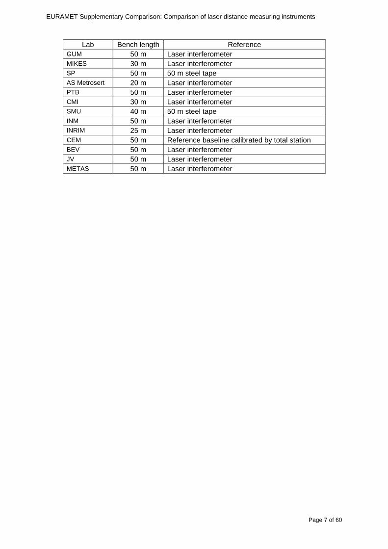
EURAMET Supplementary Comparison Comparison of laser distance measuring instruments
Page 7 of 60
Lab Bench length Reference
GUM 50 m Laser interferometer MIKES 30 m Laser interferometer SP 50 m 50 m steel tape AS Metrosert 20 m Laser interferometer PTB 50 m Laser interferometer CMI 30 m Laser interferometer SMU 40 m 50 m steel tape INM 50 m Laser interferometer INRIM 25 m Laser interferometer CEM 50 m Reference baseline calibrated by total station BEV 50 m Laser interferometer JV 50 m Laser interferometer METAS 50 m Laser interferometer
EU
RA
ME
T S
upplementary C
omparison C
omparison of laser distance m
easuring instruments
P
age 8 of 60
6 M
easurement results
In the tables below the m
easurement results and the expanded m
easurement uncertainties
are given for all laboratories and the four ED
Ms
Table 1 Measurement results for BOSCH DLE 50 EDM and expanded measurement uncertainties (k=2) The results reported by laboratories were corrected to nominal length of the measured distances
Table 2 Measurement results for BOSCH GLM 150 EDM and expanded measurement uncertainties (k=2) The results reported by laboratories were corrected to nominal length of the measured distances
EU
RA
ME
T S
upplementary C
omparison C
omparison of laser distance m
easuring instruments
P
age 9 of 60
Table 3 Measurement results for LEICA D3a and expanded measurement uncertainties (k=2) The results reported by laboratories were corrected to nominal length of the measured distances
Table 4 Measurement results for LEICA D8 and expanded measurement uncertainties (k=2) The results reported by laboratories were corrected to nominal length of the measured distances
EURAMET Supplementary Comparison Comparison of laser distance measuring instruments
Page 10 of 60
7 Measurement uncertainties The participants were asked to report detailed measurements uncertainty budgets evaluated according to the ISO Guide In table 5 the majority of the contributions are summarized as they had been reported by the participants
Tab
le 5
Sum
mar
y of
the
mos
t fr
eque
ntly
rep
orte
d m
easu
rem
ents
unc
erta
inty
con
trib
utio
ns in
mm
tak
en fr
om
unce
rtai
nty
budg
ets
repo
rted
by
the
part
icip
atin
g la
bora
torie
s
EURAMET Supplementary Comparison Comparison of laser distance measuring instruments
Page 11 of 60
8 Stability of the EDMs
Repeatability measurements showed that in the short period (less than 60 min) indications of the EDMs did not reveal any drift Large differences (~ 15 mm) were also noted between the mean values of the subsequent measurement series performed within 48 hours Considering this effect in uncertainty budget and on the basis of measurements made at the beginning in the middle and at the end of the comparison one cannot determine the drift of the results
Stability measurements Bosch DLE 50
-25
-20
-15
-10
-05
00
05
10
15
20
25
03 5 10 15 20 25 30 35 40 45 50
Length m
Dev
iatio
n fro
m m
ean
m
m
2011 02
2011 08
2012 09
Stability measurements Bosch GLM150
-15
-10
-05
00
05
10
15
03 5 10 15 20 25 30 35 40 45 50
Length m
Dev
iatio
n fr
om m
ean
m
m
2011 02
2011 08
2012 09
Stability measurements Leica DISTO D3a BT
-15
-10
-05
00
05
10
15
03 5 10 15 20 25 30 35 40 45 50
Length m
Dev
iatio
n fro
m m
ean
m
m
2011 02
2011 08
2012 09
Stability measurements Leica DISTO D8
-10
-08
-06
-04
-02
00
02
04
06
08
10
03 5 10 15 20 25 30 35 40 45 50
Length m
Dev
iatio
n fro
m m
ean
mm
2011 02
2011 08
2012 09
Fig 1 Measurements of the pilot laboratory monitoring the stability of all four EDMs at each of the measuring distances bounded by the expanded measurements uncertainty (for k=2 dashed line) The solid curves represent deviation from the arithmetic mean of the three measurements The test of the stability of the EDMs showed significant changes in the mean results in timescale months or even days A detailed analysis of the observed problems will be presented by way of example with Leica DISTO D8 and for a 10 m distance This EDM has been chosen because it is theoretically the best of the compared models with resolution of 01 mm over whole range Depending on the measured distance the EDM is characterized by some measurement uncertainty Typically the standard deviation increases along the distance Distance of 10 m was selected to minimize the impact of the uncertainty on a single measurement The more the distance from the target increases the weaker the reflected signal becomes and the more the uncertainty of a single measurement increases while for very short distances the reflected signal is so strong that it can also have a negative impact on the results
Stability over few minutes time interval
The studies performed showed that deviations from expected value are well characterized by normal distribution Results of those studies are presented in the figure below Probability density of deviations from expected value for Leica D8 for 10 m is consistent with a normal
EURAMET Supplementary Comparison Comparison of laser distance measuring instruments
Page 12 of 60
distribution with standard deviation s = 019 (blue marks ndash experimental red line ndash fitted model)
-10 -9 -8 -7 -6 -5 -4 -3 -2 -1 0 1 2 3 4 5 6 7 8 9 10
dx 01 mm
Fig 2 Distribution of results over few minutes time interval
Stability over tens of minutes time interval
Several series of measurements were made with a duration from 15 minutes to 30 minutes at a constant distance and under constant measurement conditions For most of the series changes in the average value of indications of EDMs have been observed at the level of about 02 mm However for one of the series change exceeds 05 mm (see figure below) This value leads to u = 015 mm
-06
-04
-02
0
02
04
06
08
1
0 5 10 15 20 25 30
t min
dx
mm
Fig 3 Stability of results over tens of minutes time interval
Stability in the timescale of days and months
The measurements were performed in three series of measurements over an interval of a few days The cycle of measurements was repeated twice within a few months The first three measuring series were carried out in February 2011 then in August 2011 and the last one in September 2012
In the figure below the standard deviations of individual measurements of distance are shown with error bars The dashed lines represent minimum and maximum values of individual measurements in the series of measurements
EURAMET Supplementary Comparison Comparison of laser distance measuring instruments
Page 13 of 60
Leica DISTO D8 (interval 010 m)
-06
-04
-02
00
02
04
06
08
10
12
14
series
devi
atio
n fro
m n
omin
al le
ngth
m
m
Fig 4 Results of all series of measurements for Leica DISTO D8 for a distance of 10 m
Having analyzed the graph one can see that the maximum and minimum values in each series performed at an interval of several months do not overlap The mean value in one of the series is not even in a range limited by minimum and maximum for the other series
Such a large differences between the average values appear over a time scale longer than few days This means that the laboratory couldnrsquot observe this variability when briefly examining the instrument
In the figure below probability density of all results from all measurement series was presented
-10 -5 0 5 10 15 20
dx 01 mm
Fig 5 Distribution of all results from all measurement series
Continuous red curve represents the sum of the theoretical normal distributions for each series of measurements Theoretical curve is consistent with the observed distribution
max (x1x9)
min(x1x9)
di
201102 201108 201209
EURAMET Supplementary Comparison Comparison of laser distance measuring instruments
Page 14 of 60
Estimation of uncertainty of artifact
The reproducibility of EDM is affected by random changes of mean values in time scale of days To determine di for a given EDM and a given distance the results from all nine series of measurements )( 91 xx were used
)min()max( 9191 xxxxdi minus=
where i is an index of measurement distance
Set of eleven di was determined for each EDM The figure below presents those results
0
05
1
15
2
25
0 5 10 15 20 25 30 35 40 45 50
Length m
d i
mm
DLE 50
GLM 150
D3s BT
Leica D8
Fig 6 di values for all distances for each EDM
The value of di varies widely This is especially noticeable in Bosh DLE 50 where for the neighboring distances the di values can differ by several times Each EDM is characterized by a different trend
The model assumes that long-term stability is characterized by rectangular distribution with domain described by maximal di and expected value estimated based on all of the measurements Dispersion of individual measurements (short-term stability) is described by normal distribution
The max value of di was used to estimate uncertainty u(dart) related to random changes of EDM results In order to disentangle u(dart) one should try to subtract the observed short term stability from max(di) and influences of the different alignments like zero point uzero cosine error ucos and parallelism uparal [3]
( ) 22cos
2
2
art2
32
)max(paralzero
i uuud
du minusminusminus
=
In the case of Leica DISTO D8 we obtain max(di) = 1133 which corresponds to u(dart) = 0324 mm
Table below contains values of u(dart) estimated for all the four EDMs
EURAMET Supplementary Comparison Comparison of laser distance measuring instruments
Page 15 of 60
Table 6 Values of u(dart) for all the four EDMs
EDM u(dart) (mm)
Bosch DLE 50 0308
Bosch GLM 150 0197
Leica DISTO D3a BT 0149
Leica DISTO D8 0324
Additional stability test of EDMs
The suspected main factors responsible for the change of EDMs indications are 1) Effects of electronics ndash resulting from unstable operation of the EDM 2) Effects of mechanics ndash impact of transport of the EDM between laboratories 3) Effects of geometry ndash alignment repeatability of the EDM during measurements
Two additional experiments were conducted in order to determine which factors have the greatest impact on the results Leica DISTO D3a BT was used for these tests
a) Static test
During the measurements the EDM was immobilized on a bench Measurements were made at a distance of 10 m in a controlled environment The measurement results are presented in the figure below
-04
-03
-02
-01
00
01
02
03
04
1 2 3 4 5 6 7 8 9 10 11 12 13 14 15 16 17 18 19 20
measure
dx
mm
Fig 7 Static stability test results
Each point represents the mean value of 15-20 measurements This test covers about 6 hours of EDM work The standard deviation is s = 009 mm
b) Dynamic test
Measurements were made at a distance of 10 m in a controlled environment After each series of measurements the EDM was removed from the bench shaken and squeezed The aim was to simulate the conditions during transportation This test covers about 6 hours of EDM work Measurement results are presented in the figure below
EURAMET Supplementary Comparison Comparison of laser distance measuring instruments
Page 16 of 60
-04
-03
-02
-01
00
01
02
03
04
1 2 3 4 5 6 7 8 9
measure
dx
mm
Fig 8 Dynamic stability test results
The standard deviation for this test is s = 015 mm and is greater than in the static test
The average standard deviation of three measurement series was estimated using the data from the comparison The value s = 009 mm is similar to the result in the static test
The estimated uncertainty associated with the artifact for this EDM is uart = 015 mm (see table above) The same value u = 015 mm was estimated from the stability test in the scale of tens of minutes Both values are close to the value of standard deviation for the dynamic test
These results may lead to the conclusion that the level of the effects of electronics mechanics and geometry have a similar impact on the long-term stability Due to this fact it is difficult to identify which of these factors has the greatest impact on the observed measurement results
EURAMET Supplementary Comparison Comparison of laser distance measuring instruments
Page 17 of 60
9 Reference values The standard approach is to use weighted mean for determining the reference value xref [12] This is calculated by the mean of all measurement values xi weighted by the inverse square of the standard uncertainties u(xi) associated with the measurements and using these values the largest consistent subset of the sample is determined However checking the consistency of the sample without taking into account the uncertainty associated with the artifact leads to erroneous recognition of the consistent subset We propose to add uart to the uncertainty of each laboratory at the beginning of the calculation
( ) )()( 222iartic xuduxu +=
Thereby the uncertainty associated with the artifact will be taken into account during the consistency check
sum
sum
=
==n
i ic
n
i ic
i
ref
xu
xu
x
x
12
12
)(
1
)(
The pilot laboratory contributed only by its first measurements to the reference values The weighted mean approach requires the individual uncertainties from the laboratories to be estimated according to a common approach (as they should be since all participants were requested to estimate the uncertainties according to the ISO Guide) The standard uncertainty u(xref) of the reference value is calculated by combining the individual uncertainties
sum=
=n
i ic
ref
xu
xu
12
2
)(
1
1)(
The χ2 test was applied in order to estimate xref from the largest consistent subset [1]
EURAMET Supplementary Comparison Comparison of laser distance measuring instruments
Page 18 of 60
Table 7 Reference values and associated standard uncertainties based on weighted mean
Distance Bosch DLE 50 Bosch GLM 150 Leica DISTO D3a BT
Leica DISTO D8
mm xref u(xref) xref u(xref) xref u(xref) xref u(xref)
300 299694 0138 300475 0084 300353 0071 300177 0113
5000 4999900 0139 4999774 0090 5000020 0074 4999659 0111
10000 10000041 0146 9999776 0096 10000285 0077 10000336 0114
15000 14999945 0154 14999781 0120 15000176 0080 15000258 0117
20000 19999804 0175 19999423 0124 20000112 0086 20000581 0118
25000 24999955 0186 24999526 0128 25000321 0094 25000754 0124
30000 29999586 0193 29999956 0138 30000140 0103 30000675 0129
35000 34999779 0235 35000051 0156 35000022 0119 35000844 0153
40000 40000185 0279 40000250 0159 40000476 0132 40001167 0151
45000 44999576 0315 45000208 0165 45000391 0155 45000974 0156
50000 49999983 0324 50000344 0169 50000319 0156 50001137 0157
EURAMET Supplementary Comparison Comparison of laser distance measuring instruments
Page 19 of 60
10 Deviations from reference values The following figures show results from NMIs for all of the distances Reference value is represented by a bold black line
Bosch DLE 50
-30
-25
-20
-15
-10
-05
00
05
10
15
20
25
30
0 5 10 15 20 25 30 35 40 45 50 55
Length m
Dev
iatio
n fr
om n
omin
al le
ngth
m
m
MIKES
SP
Metrosert
PTB
CMI
SMU
INM
INRIM
CEM
BEV
JV
METAS
GUM
Ref
Bosch GLM 150
-20
-15
-10
-05
00
05
10
15
20
0 5 10 15 20 25 30 35 40 45 50 55
Length m
Dev
iatio
n fr
om n
omin
al le
ngth
m
m
MIKES
SP
Metrosert
PTB
CMI
SMU
INM
INRIM
CEM
BEV
JV
METAS
GUM
Ref
Fig 9 Deviations from reference values
EURAMET Supplementary Comparison Comparison of laser distance measuring instruments
Page 20 of 60
Leica DISTO D3a BT
-20
-15
-10
-05
00
05
10
15
20
0 5 10 15 20 25 30 35 40 45 50 55
Length m
Dev
iatio
n fr
om n
omin
al le
ngth
m
m
MIKES
SP
Metrosert
PTB
CMI
SMU
INM
INRIM
CEM
BEV
JV
METAS
GUM
Ref
Leica DISTO D8
-20
-15
-10
-05
00
05
10
15
20
0 5 10 15 20 25 30 35 40 45 50 55
Length m
Dev
iatio
n fr
om n
omin
al le
ngth
m
m
MIKES
SP
Metrosert
PTB
CMI
SMU
INM
INRIM
CEM
BEV
JV
METAS
GUM
Ref
Fig 9 Deviations from reference values (continued)
The deviations Di from reference value xref are calculated by
refxxD ii minus=
For calculating the expanded uncertainty of these deviations U(Di) the corresponding uncertainties u(xi) and u(xref) cannot simply be geometrically added because the values xi and xref are correlated Due to the random changes described in section 6 uncertainty u(dart) was added [2] It can be shown that the expanded uncertainty U(Di) is given by
)()()(961)( art2
ref22 duxuxuDU ii +minus=
when xi belongs to the largest consistent subset and
)()()(961)( art2
ref22 duxuxuDU ii ++=
EURAMET Supplementary Comparison Comparison of laser distance measuring instruments
Page 21 of 60
otherwise The deviations from the reference values are given in various figures and tables below The uncertainty bars in the figures correspond to the expanded uncertainties U(Di) (k = 196)
Fig 10 Deviations from reference values
EURAMET Supplementary Comparison Comparison of laser distance measuring instruments
Page 22 of 60
Fig 10 Deviations from reference values (continued)
EURAMET Supplementary Comparison Comparison of laser distance measuring instruments
Page 23 of 60
Fig 10 Deviations from reference values (continued)
EURAMET Supplementary Comparison Comparison of laser distance measuring instruments
Page 24 of 60
Fig 10 Deviations from reference values (continued)
EURAMET Supplementary Comparison Comparison of laser distance measuring instruments
Page 25 of 60
Fig 10 Deviations from reference values (continued)
EURAMET Supplementary Comparison Comparison of laser distance measuring instruments
Page 26 of 60
Fig 10 Deviations from reference values (continued)
EURAMET Supplementary Comparison Comparison of laser distance measuring instruments
Page 27 of 60
Fig 10 Deviations from reference values (continued)
EURAMET Supplementary Comparison Comparison of laser distance measuring instruments
Page 28 of 60
Fig 10 Deviations from reference values (continued)
EU
RA
ME
T S
upplementary C
omparison C
omparison of laser distance m
easuring instruments
P
age 29 of 60
Table 8 Deviations from the reference value (given at the top of the table) and expanded uncertainties (k=196) of such deviations for BOSCH DLE 50
Table 9 Deviations from the reference value (given at the top of the table) and expanded uncertainties (k=196) of such deviations for BOSCH GLM 150
EU
RA
ME
T S
upplementary C
omparison C
omparison of laser distance m
easuring instruments
P
age 30 of 60
Table 10 Deviations from the reference value (given at the top of the table) and expanded uncertainties (k=196) of such deviations for Leica DISTO D3a BT
Table 11 Deviations from the reference value (given at the top of the table) and expanded uncertainties (k=196) of such deviations for Leica DISTO D8
EURAMET Supplementary Comparison Comparison of laser distance measuring instruments
Page 31 of 60
11 En Tables Results with En gt 1 are marked with red color in Tables below En values are calculated by Di U(Di) with Di and U(Di) as given on page 19
Table 12 BOSCH DLE50
Lab Distance (mm) 300 5000 10000 15000 20000 25000 30000 35000 40000 45000 50000
MIKES -058 017 -019 -023 035 -002 -096 SP 020 019 006 005 009 059 064 037 028 097 001
Metrosert -030 -031 -003 018 032 PTB 001 029 022 -006 011 -036 001 -023 -075 -083 001 GUM -033 -005 -018 -009 000 006 017 005 -026 -028 019 CMI -003 020 -009 004 005 -022 028 SMU 006 -049 -034 -023 -017 -057 051 039 021 INM 032 031 037 006 020 005 -079 -119 -272 -260 -269
INRIM 025 -013 000 096 CEM -032 -022 -041 -039 -004 -038 080 001 -094 -047 BEV -010 007 000 -001 008 -011 037 013 -001 008 -001 JV -019 -016 025 -055 055 060 068 163 122 060 089
METAS 038 012 -005 007 -107 004 -024 002 -070 037 -052
Table 13 BOSCH GLM150
Lab Distance (mm) 300 5000 10000 15000 20000 25000 30000 35000 40000 45000 50000
MIKES 005 -002 019 018 027 019 062 SP 003 068 029 023 051 008 015 016 -005 -001 038
Metrosert -061 -011 -022 -021 -003 PTB 066 074 062 062 034 053 047 048 047 091 064 GUM -007 -014 007 -018 000 023 020 033 014 032 038 CMI -057 -032 -030 -064 -050 -047 000 SMU 023 -024 -060 012 062 001 -003 050 047 INM -022 017 -003 002 -003 054 005 -006 016 -022 -055
INRIM 079 -052 -050 -026 -034 -042 CEM 002 002 -034 -020 -029 -077 -077 -077 -074 -104 BEV -004 -002 -007 010 -042 -042 -029 -011 -028 -022 -030 JV 003 015 040 011 -020 021 -029 -005 028 036 058
METAS -047 -020 005 002 -012 -033 -054 -065 -053 -082 -040
Table 14 Leica DISTO D3a BT
Lab Distance (mm) 300 5000 10000 15000 20000 25000 30000 35000 40000 45000 50000
MIKES 008 094 050 -011 028 051 045 SP 033 038 056 017 053 065 076 051 017 071 011
Metrosert -060 -004 -037 -014 -002 PTB 067 000 070 030 089 062 061 081 124 050 072 GUM 023 019 035 008 038 053 029 058 070 064 063 CMI -001 -004 027 -011 011 034 -033 SMU 002 -013 -019 007 -013 -055 045 -013 -042 INM 002 -039 -058 001 002 -045 -080 -051 -102 -101 -378
INRIM 070 -020 063 101 CEM -028 -004 -004 -064 003 -002 -050 -022 -093 -160 BEV -032 -019 -019 004 -011 -037 -017 -002 -025 005 012 JV 027 019 027 042 046 039 043 048 072 115 024
METAS -091 -008 -102 -098 -111 -103 -092 -080 -073 -108 -043
EURAMET Supplementary Comparison Comparison of laser distance measuring instruments
Page 32 of 60
Table 15 Leica DISTO D8
Lab Distance (mm) 300 5000 10000 15000 20000 25000 30000 35000 40000 45000 50000
MIKES 025 013 058 036 038 061 022 SP 057 026 040 016 013 016 025 017 -007 -019 007
Metrosert -021 006 -016 -043 -019 PTB 040 011 035 -005 -011 -002 -004 035 047 022 069 GUM -028 005 -025 031 039 -015 029 048 041 052 072 CMI -104 -026 -072 -057 -006 -017 -015 SMU -067 -017 -051 -026 -016 -054 -004 -001 -016 INM 021 -014 009 003 -017 -031 -010 007 029 036 041
INRIM 076 -024 -004 047 -007 083 CEM 004 -009 002 -033 -051 -059 -097 -077 -116 -134 BEV -057 -014 -051 -093 -024 -027 -021 -036 -038 -028 -041 JV 014 031 047 030 044 043 035 056 093 108 030
METAS 035 007 026 038 -013 -024 -011 -048 -089 -074 -066
12 Conclusions It was the first comparison of EDMs For most of the laboratories it was an important opportunity to validate their measurement instrumentation and procedure It allowed to become aware of potential problems and to take corrective actions in changing the procedure
For the evaluation of the reference value the weighted mean approach has been chosen although the consistency check according to procedure A of Ref [1] failed in many cases A more complicated procedure for the evaluation of the reference value was proposed which slightly changes the uncertainty of the reference value
In total there were 23 En values larger than 1 This represents 47 of the full set of 482 results It is less than the 5 of possible values being out of the expanded uncertainty of the reference value for k=2
The uncertainty of the results mainly comes from the uncertainty of the reproducibility It is difficult to distinguish between Labrsquos calibration and measurement capability
The comparison shows a global compliance with declared CMCs independently of whether some participant can have a high percentage of values not compliant with its CMC due to the influence of the artifact and the estimation of its uncertainty
13 References [1] M G Cox The evaluation of key comparison data Metrologia 39 589 ndash 595 (2002)
[2] R Thalmann EUROMET 677 ndash Steel Tape Measures Final report (2004)
[3] F Pollinger personal communication
EURAMET Supplementary Comparison Comparison of laser distance measuring instruments
Page 33 of 60
Appendix 1 Description of the measurement equipmen t as reported by the laboratories
A11 MIKES Finland
Short description of measurement bench
MIKES interferometric bench is situated in an underground laboratory with air temperature and humidity control Typically air temperature is 20 plusmn 01 degC and humidity 45 plusmn 2 RH The linear guide on the top of the concrete beam comprises two parallel round shafts with adjustable fixtures every 1 m A carriage with ball bush bearings is moved along the rail and location of it is measured with reference interferometer HP-5529A Temperature of air is measured with 6 pt100 sensors and Keithley 2010 multimetre with 4-wire resistance mode Air pressure and humidity are measured with Vaisala PTU200 Updated Edleacuten equation by Boumlnsch amp Potulski is used for calculation of refractive index of air
For EDM calibration on the other end than laser interferometer is a fixed reference plate which is adjusted perpendicular to the laser beam Next to the reference plate is an adjustable base for EDM instrument with which it can be adjusted to point parallel and coincident with measurement arm of the interferometer A target plate adjusted perpendicular to laser beam is fixed to the carriage The calibration followed Abbe principle with some millimetre uncertainty in offset adjustment
First reference interferometer is set to zero when the target plate and reference plate are in contact then EDM is positioned and adjusted in its base The rear surface of the EDM is also slightly pressed against reference surface behind it Then the readings from both instruments are collected at selected locations For this calibration there is no fine adjustment of the target position so there are typically deviations of up to few millimetres from nominal locations Results are averages of 3-4 measurements
Additional remarks
The CMC entry MIKES has for EDM calibrations is based on calibration of length scales of high quality total stations and laser trackers This type of EDMs used in this comparison are not accurate enough for truly testing of MIKES calibration measurement capability
EURAMET Supplementary Comparison Comparison of laser distance measuring instruments
Page 34 of 60
A12 SP Sweden
Short description of measurement bench
The bench consists of a simple aluminium Uminusshaped profile with polished steel pins acting as supports for the tape The bench is a little over 50 m long and works as support for the reference tape and the calibrated EDMs simultaneously
Length measurement instrument
Comparison with reference steel tape
Temperature measurement system number and location of sensors
The tape temperature is continuously registered in 6 points equally distributed along the bench The air temperature is monitored during the measurements but not used for corrections
Additional remarks
The EDM support is placed approximately 2 cm vertically above the tape No visual aid is used
EURAMET Supplementary Comparison Comparison of laser distance measuring instruments
Page 35 of 60
A13 AS Metrosert Estonia
Short description of measurement bench
The 21-m bench is located in the designated corridor-like laboratory room The lab is air-conditioned and the stability of temperature is typically plusmn05 ordmC There are three humidity and temperature sensors in room for stability and gradient monitoring
Two stainless steel rails running in parallel are made of 3-m long rods The rails lay without fixed attachment on metal supports which are mounted on concrete base The base rests on pillars made of bricks
Length measurement instrument
Laser-interferometer system Renishaw ML10 was used as length measurement instrument
Laser interferometer gets temperature humidity and pressure data from itrsquos own measurement system EC10
Additional remarks
Due to the length of the bench only measurements up to 20 m could be made Five measurement series were made with each EDM
EURAMET Supplementary Comparison Comparison of laser distance measuring instruments
Page 36 of 60
A14 PTB Germany
Short description of measurement bench
The measurements were performed on the 50 m geodetic base of the PTB The comparator consists of a 50 m rail The laboratory is equipped with a network of 21 temperature sensors spaced by 25 m along the bench As depicted in fig 1 the EDM is mounted at one end of the comparator the reflector is fixed vertically on the carriage A large retroreflector is mounted approximately 150 mm below the EDM reflector on the carriage reflecting the beam of the reference interferometer The deviation of the length due to tilting carriage (Abbe error) has been investigated along the bench by comparison of two interferometers It remains smaller than 100 microm The distance of the first position of 300 mm with respect to the back side of the EDM is determined by a gauge block of 300 mm length and a thickness of 10 mm This procedure is depicted for one of the comparison standards in figure 2
For the calibration the desired positions are programmed After the carriage reaches a measurement position the operator waits for another 30 s for the carriage to settle In control experiments the remaining movement between positioning and measurement remained smaller than 2 microm The operator then activates the measurement of the EDM reads the indicated position and writes it down The procedure is repeated for twelve times at every position the mean of the 12 measurements represents the ldquoindicated distance by the EDMrdquo All measurements of a single run at one position are performed within approximately one minute The complete measurement was repeated for four times
Length measurement instrument
The reference length is determined by a frequency-calibrated laser interferometer (Agilent 5519A) The reference interferometer is set up in Michelson geometry the signals being digitalised by a Heidenhain IK 121 card The index of refraction is determined by the external weather station of the geodetic base consisting of 21 Pt-100 temperature sensors spaced 25 m along the bench two humidity sensors (Testo 650) and two pressure sensors (Setra 370 and DPI 141) The environmental parameters are used to determine the index of refraction for the reference measurement deploying the modification of the Edleacuten equation by Boumlnsch and Potulski
EURAMET Supplementary Comparison Comparison of laser distance measuring instruments
Page 37 of 60
A15 CMI Czech Republic
Description of measurement bench
The EDMs were measured on 30 m long measuring bench equipped by laser interferometer (LI) Renishaw ML10 (pic 1 and 2) calibrated traceable to national standard of length and quantities of environmental sensors The target plate and retroreflector of the LI were fixed on a moving part of the bench and each EDM was fixed in horizontal position by clamps (pic 3) LI and EDM are placed on opposite ends of bench the Abbe offset was lt10 mm for some of them and lt50mm for all The value of LI was reset (to zero) at position corresponding to the rear of the EDM (using 3D measuring arm FARO Quantum with uncertainty about 27microm) The perpendicularities of the EDM stop as well as target plate to the beam were also checked by FARO) Each EDM was 3x replaced and aligned the measurement (reading) was repeated 6 times for each alignment and position the mean value of these 3x6 measurements is stated in tables with results The uncertainty claimed covers the statistical uncertainty of single readings Only in case of Leica D8 (the best performing EDM in this comparison) we state also the uncertainty corresponding to the mean of 6 readings in last column (this uncertainty is smaller and better illustrates our CMC)
Length measurement instrument
- Laser interferometer Renishaw - Laser 633 nm Type ML10 - Compensator EC10 - 3D measuring arm FARO Quantum - 3D measuring arm FARO Quantum
EURAMET Supplementary Comparison Comparison of laser distance measuring instruments
Page 38 of 60
A16 SMU Slovakia
Short description of measurement bench
No bench is available at the SMU the measurements are being carried out in the underground corridor of the laboratory building with length of 428 m
The 50 m steel measuring tape KINEX was used as the reference laid on the floor and pulled by the force 50 N (the same force as had been applied during its calibration at the SMU) The calibration of reference tape was done at the SMU using ULM3m Zeiss with laser interferometer Agilent 5529 B (ie per 3 m parts)
Three mercury thermometers with the resolution of 01 degC were used along the measurement path each of them laid onto the tape and located at 667 m 1990 m (instead of 20 m because of this was one of measuring points) and 333 m respectively Each of them thus corresponded approximately to one third of the measured steel tape section
Regarding the 03 m measuring point the ULM3m Zeiss length measuring machine was used with the 300 mm gauge block as the reference
Length measurement instrument
We used our own target plate being fixed perpendicularly (within uncertainty stated) to the construction equipped with nonius and the camera holder transported manually along the steel tape The second construction was fixed to the tape by such a way that zero line of the tape corresponded to the rear of EDM (within uncertainty stated)
The position of the target is read on the monitor and 20 repeated readings of the EDM data took place in each measuring point (multiples of 5 m up to 40 m)
Concerning 03 m the 300 mm gauge block was fit between the target plate and the construction with EDM The distance of the EDM rear from the target plate corresponded to the length of gauge block (within uncertainty stated)
Additional remarks
The identical measurement method was used as we use to do within our calibration service although the results reporting is different ndash we provide the regression line calculated from the measurement of irregularly distributed points and corresponding uncertainty (k = 2) in the form of [a bL] mm (ie the same coefficients for each length in the range (0 ndash 42) m)
SMU hasnrsquot got this category in CMC tables
EURAMET Supplementary Comparison Comparison of laser distance measuring instruments
Page 39 of 60
A17 INM Romania
Short description of measurement bench
Geodesic base located in the basement of the laboratory with nominal length equal to 50 m having a mobile carriage thet support both laser He-Ne retroreflector and the target of the laser distance measuring instrument in the front of geodesic base exists a support where are aligned both laser interferometer and the laser distance measuring instruments
Length measurement instrument
Laser interferometer type Hewlett Packard model 5526 A with nominal length equal to 50 m resolution 0001 mm
U = 02 microm +0510-6L
Additional remarks
During the measurements the maximum gradient of temperature was equal to 05 degC
EURAMET Supplementary Comparison Comparison of laser distance measuring instruments
Page 40 of 60
A18 INRIM Italy
Short description of measurement bench
The facility for long distance measurements is located in a corridor of the gallery devoted to dimensional metrology The structure consists in a 28 m long rail fixed to a series of pillars which rest directly on the ground released from the vibrations of floor and wall The measuring system is based on a heterodyne interferometer whose mobile arm consists of a hollow retro-reflector mounted on a structure that can run along the rail so-called carriage A photograph of the facility is presented in Fig1
The carriage is moved by a micro-step motor the motor driver receives a digital pulse and converts it into an electrical pulse to run the motor Each pulse causes a rotation of the motor shaft of one step which amounts to 11000 of a complete revolution of the shaft If the pulse frequency increases the rotation becomes continuous with a speed that is directly proportional to the pulse frequency The speed ranges between few microms up to 27 ms with a resolution of 03 microms
Since the carriage must move back and forth automatically for a distance of almost 30 m a remote control to send pulses to the motor driver was implemented It consists of two parts a radio command which allows to set some general parameters of the carriage movement such as the movement direction and mode of travel (slow or fast) and a fast command which is performed by an amplitude modulated laser beam placed at the beginning of the track oriented towards the carriage A photo detector placed above the carriage receives the modulated laser beam which is transformed into pulses to be sent to the driver of the motor The modulation of the laser beam is implemented by a LabView program that controls a digital output of the data acquisition device
Length measurement instrument
The length measurement instrument is based on a heterodyne incremental interferometer The main beam of the interferometer with frequency f1 is generated by a frequency stabilized
EURAMET Supplementary Comparison Comparison of laser distance measuring instruments
Page 41 of 60
He-Ne laser calibrated with respect to the INRIM length standard and sent to the measurement arm the second beam is a portion of the first one diffracted by an acousto-optic modulator (AOM) with frequency f2 = f1 + 80 MHz The reference detector acquires the beat note signal at 80 MHz while the measurement detector acquires a signal at 80 MHz whose phase is varied due to the displacement of the retro-reflector moving on the rail In figure 2 the optical design of the interferometer is presented
Two different measuring techniques have been implemented
1 the ldquophase measuringrdquo technique based on fringes counting with a relative uncertainty of 5middot10-7 but limited at the maximum carriage speed of 3 cms
2 the ldquoDoppler frequency measurementrdquo technique for higher carriage speed based on the measurement of the Doppler frequency shift while the carriage runs
The second technique was validated by means of the comparison with the first technique at low speed with an agreement of the order of 3middot10-6 hence the Doppler frequency method could be considered validated within 01 mm over the whole rail path with the advantage of reducing the time needed to cover long distances so it was used for the EDM comparison
In order to obtain the distance covered by the carriage according to technique 2 the Doppler frequency is measured by a commercial high-performance counter (a Pendulum CNT-90) without dead time based on time stamping then it is converted in speed and integrated over time according to the following formula
( ) ( )int minus=minus= tffn
dtn
ffdairair
λλ
2
1
2
1
where d is the distance covered by the carriage f is the frequency of the measuring signal with the carriage at rest frsquo the frequency of the measuring signal with the carriage moving λi
is the wavelength of the laser in vacuum n - air is the air refractive index and ti is the integration time The difference frsquo-f is just the Doppler frequency due to the moving carriage
The time interval measurement resolution of the instrument is 100 ps and the time base is
EURAMET Supplementary Comparison Comparison of laser distance measuring instruments
Page 42 of 60
connected to the INRIM UTC so that the measurements of the Doppler frequency and the integration time are extremely accurate The environmental parameters such as air temperature atmospheric pressure partial pressure of water were monitored during the measurement process in order to calculate the value of air refractive index according to the Edlenrsquos formula
Comparison set-up
The different technical solutions adopted for the EDMs and for the target plate positioning are discussed in this paragraph and sketched in figure 3
Fig 3 picture of the EDM and target positioning area
Target plate positioning
In order to use the provided target plate an ad-hoc mounting was manufactured at INRIM it consists in a sort of picture frame made in aluminum which slightly clamps the target folded in half and gives it the necessary stiffness to be a reproducible target The upper part of the frame is L-shaped and allows it to be fixed to the carriage structure by means of two screws The rear part of the target mounting is depicted in figure 4 The target mounting was considered necessary because of the poor stiffness and planarity of the plastic target With the aluminium frame a planarity better than 01 mm was guaranteed The target plate is placed few centimetres next to the retro-reflector and normal to the interferometer beam axis since the EDM laser should be as close and parallel as possible to the reference beam
EURAMET Supplementary Comparison Comparison of laser distance measuring instruments
Page 43 of 60
Fig 4 picture of the rear part of the target plate mounting
EDMsrsquo positioning
The EDMs are placed on a cradle-like platform which is able to adjust the inclination of the EDM along the longitudinal axis (pitch angle) The platform height allows the EDMs to be at approx the same height as the interferometer beam A crucial role was played by the stop-wall placed behind the platform since it represents the ldquozero pointrdquo for all the length measurement Hence a particular effort was devoted to align the stop-wall so that it was normal to the interferometer beam axis and parallel to the target plate
Fig 5 detail of EDMsrsquo positioning the cradle-like platform and the stop-wall are well visible
EURAMET Supplementary Comparison Comparison of laser distance measuring instruments
Page 44 of 60
Target and stop-wall alignment
In order to have the stop-wall parallel to the target plate and normal to the interferometer beam axis the following procedure has been used
1) the stop-wall and the target plate were roughly placed trying to set them parallel and normal to the rail by eye (ie within few millimeters)
2) in order to check if the target was normal to the rail one EDM was positioned on the platform the pitch and yaw angles of the EDM were adjusted by observing the position of the EDM laser spot on the target plate when the target is moved along the rail fixed position means laser beam parallel to the carriage movement Then the target was moved until the end of the rail and a thin mirror was kept in contact with it hence observing the EDM laser reflected by the mirror it was possible to adjust the target tilt acting on the screws until the laser beam is reflected back to the source
3) finally in order to check the parallelism between the stop-wall and the target a tool made by a laser pointing orthogonally to its base was used the base was leant against the stop-wall and the laser was centered on the target when the target is near then the target was moved until the end of the rail hence observing the spot of the laser on the target it was possible to adjust the stop-wall orientation
The residual misalignment errors which we were not able to eliminate were kept into account in the uncertainty budget
Measurement of the first 30 cm
Due to the geometry of our set-up it was not possible to perform the first point of measurement by means of the interferometer indeed the carriage (hence the target) is not able to go in contact with the stop-wall
Fig 6 measurement of the first 30 cm the ruler touching the stop-wall and the target and the mechanical probe (in the back) touching the carriage are visible
EURAMET Supplementary Comparison Comparison of laser distance measuring instruments
Page 45 of 60
So a ruler made of aluminum with rounded ends and nominal length equal to 30 cm was adopted to set the distance between the target plate and the stop-wall for the first point of measurement as it is shown in figure 6 The ruler whose length was measured by a CMM machine was inserted between the target and the stop-wall leaning against the latter and the carriage was carefully moved towards the stop-wall until the target lightly touched the ruler A mechanical probe that touches the carriage structure when carriage is in the ldquo30 cmrdquo position was used as a reference measurement to check the repeatability of this distance after each measurement set
Fig 7 detail of the mechanical probe touching the carriage
Environmental parameters
The environmental parameters such as air temperature atmospheric pressure and humidity were monitored during the whole measurement process in order to calculate the value of air refractive index according to the Edlenrsquos formula
Among these parameters the temperature distribution along the mobile arm of the interferometer was our main concern mainly for two reasons
1 the temperature control of the gallery was not perfectly working during the measurement period so temperature drifts had to be monitored
2 longitudinal temperature gradients due to non uniform heating and to the presence of electronic instruments were pretty high
To the purpose 14 thermometers were uniformly dislocated along the rail and automatically recorded for all the measurement period Both temporal drifts and gradients along the path have been taken in account in the uncertainty budget In any case maximum temperature differences along the rail are within 1 degC In fig 8 an extract from the acquisition file is shown
Unfortunately the air conditioning system did not work well during the measurement campaign hence the measurements were performed at a mean temperature of 209 degC
EURAMET Supplementary Comparison Comparison of laser distance measuring instruments
Page 46 of 60
Fig 8 each curve represents the temperature distribution along the rail during the measurements campaign
Carriage waving
Since the rail is not perfectly straight and the measurement laser is not coincident with the measurement beam the Abbegrave error due to waving of the target must be considered A quantitative measurement and a qualitative measurement were carried out With an electronic level placed on the carriage the straightness on the vertical plane has been mapped with a half meter resolution (the data are reported in fig 9) With a laser placed on the carriage the horizontal and vertical waving are qualitatively compared by looking at the movements of the light spot on a target fixed to the rail end As a conclusion the horizontal and vertical waving are comparable in magnitude and the peak to peak error is of the order of 300 arcseconds
Fig 9 vertical waving of the target measured by an electronic level placed on the carriage
EURAMET Supplementary Comparison Comparison of laser distance measuring instruments
Page 47 of 60
Measurement procedure
The measurements were carried out according to the following procedure
The target was set in the starting position with the procedure described above
In sequence the four EDMs are positioned on the base the horizontal and vertical tilt are adjusted and the distance measurement is recorded An additional fifth EDM (Bosh DLE 150 property of INRiM) was included in the measurement sequence Each EDM is placed on the base and gently pushed against the reference wall in such a way that the measurement laser beam starting point is the same for all EDMs Than the horizontal and vertical angles were adjusted in order to hit the central point of the target indicated with two black marks (see pictures 3 and 6) with ldquovisualrdquo alignment The measurement button is then pressed several times (typically 5) and the average reading is recorded Typical dispersion between readings is within few last digit units In case the dispersion between readings is too large the anomaly is recorded
The carriage was then moved in the next position (about 5 m) and the measurement sequence was repeated for the 5 EDMs The operation is repeated up to 25 m The 25 m measurement is than repeated again as well as all the points till the first one so that each point is measured twice each set Since the carriage movement is ldquoopen looprdquo the positioning of the carriage was not exactly in the nominal 5 m intervals For each positioning the incremental displacement is measured by the interferometer in the Doppler mode Finally the measured values were averaged in order to give a single value for each nominal position
At the end of the measurement set when the carriage is at the 30 cm position again the sum of the interferometric measurements should be very close to zero The residual value is compared with the difference between the first and the final measurements of the mechanical probe The difference must be within the uncertainty of the Doppler technique otherwise some error occurred in the measurement set that must be repeated
At the end of the session 10 complete sets of measurements recorded from the 20th to the 30th of January 2012 have been considered for this report
Additional remarks
Effect of laser pointing
During a preliminary set of measurements we noticed a strong and unexpected dependence of the measurement result on the position of the laser spot on the target Indeed since no particular instructions were given about the relative position of the laser spot on target position (except to exclude the central joint between the two halves) we decided to work relatively close to the right side of the target -closer to the interferometer beam- in order to reduce the Abbegrave error We noticed very large errors at large distances in particular of the Leica DISTO D3a (see figure 10)
EURAMET Supplementary Comparison Comparison of laser distance measuring instruments
Page 48 of 60
Fig 10 errors of each EDM In a preliminary set of measurements
We also noticed that this error was strongly dependent on the position of the spot on the target For this reason we carried out a set of measurements at the maximum length in different positions of the target from one edge to the other according to figure 11 The results are reported in table V
EDM A B C D E
Leica D3a -4 +1 0 +24 +43
+2 0 +42 +40
-1 0 +38
Leica D8 0 0 0 2 +7
0 +12 +23
table V deviations (in mm) from the length measured at point C aiming the laser spot at different positions of the target (notations as in figure 11)
We tried to find an explanation to this effect in the shape of the laser spot if the spot was
EURAMET Supplementary Comparison Comparison of laser distance measuring instruments
Page 49 of 60
particularly defocused or had high diffraction some of the energy could fall out of the target and affect the measurement result In fact the images of the spots (shown in fig 12) do not support this hypothesis Finally we decided to use the center of the (half) target for the comparison
Changing the target
In order to investigate the influence of the target on the measurements a cardboard foil (400 x 400) mm was fixed to the target mounting and a complete set of measurements was performed The results reported in figure 13 and 14 do not show any evidence of a possible dependency of the EDM measurement on the target kind
EURAMET Supplementary Comparison Comparison of laser distance measuring instruments
Page 50 of 60
Measurement at 50 m
Although we are not able to perform traceable length measurements beyond 28 m we wanted to get a sense of EDMs behaviour at longer distances So a target (represented by a rack side wall) was placed at approximately 50 m one after the other the EDMrsquos were positioned on the base and pointed towards the target The measurements were repeated then the target was replaced by the target used for the comparison and a third set of measurements were performed To our great surprise all the EDMrsquos were in good agreement (within 2 or 3 mm for each set of measurement) even those which showed errors of the order of five to ten millimeters at 25 m namely BOSCH DLE 50 and LEICA DISTO D3a Therefore each set of measurements was averaged and the deviations from the mean value are reported in figure 15
EURAMET Supplementary Comparison Comparison of laser distance measuring instruments
Page 51 of 60
Fig 15 Deviations from average value of the measurements At 50 m
EURAMET Supplementary Comparison Comparison of laser distance measuring instruments
Page 52 of 60
A19 CEM Spain
Short description of the measurement bench
To make the measurements of EDMs we have used a reference line made of adjustable supports fixed on a wall of the laboratory Each support is nominally separated five metres from the previous one so we can generate reference lengths up to fifty metres with a pitch of five metres The supports are designed to accommodate both targets and handheld EDMs Distances between supports were measured by using a total station traced to national standards The relative angles of the bases have been measured and corrected
Fig 1 - View of three consecutive supports of the 50 m baseline (left) Lab technician situating an EDM on the first support of the baseline (right)
Length measurement instrument
The baseline was calibrated by using a total station Leica TDA5005 with spherical reflector the calibration uncertainty being 02 mm for k = 2
The target is provided by the comparison The quality of the target was judged as not good due to geometrical constructive errors and the lack of rigidity and stability We measured the flatness of the target surface the distance edge-surface and the angle between them by using a 3D coordinate measuring machine The results of flatness and angle were included in the uncertainty budget and the distance EDM-target was corrected for each EDM due to each beam impinged on a different point of the target
We were not able to measure the distance 0 to 03 m because the baseline pitch is 5 meters and although we are able to measure shorter values in a different facility the target was not appropriate for our bench
EURAMET Supplementary Comparison Comparison of laser distance measuring instruments
Page 53 of 60
Fig 2 - View of an EDM on the first support of the baseline (left) A closer look showing the support adjustments and the origin plate (right)
Fig 3 - View of the comparison target on one of the supports of the baseline (left) A closer look showing the target edge against the support rigid reference (right)
Measurement method
The measurements were carried out by comparison against the known values of the calibrated baseline (metallic references on supports)
Environmental conditions were maintained within the following limits
- Temperature 20 ordmC plusmn 05 ordmC
- Humidity 45 plusmn 10
Each laser distance measuring instrument was placed at the first support of the base and aligned so that the laser beam was perpendicular to the target as indicated by the comparison protocol
For each measurement we took the average of thirty measurements It permitted us to evaluate the repeatability of the instrument
EURAMET Supplementary Comparison Comparison of laser distance measuring instruments
Page 54 of 60
A110 BEV Austria
Short description of the measurement bench
Fig 1 Carriage of tape bench View from the laser interferometer side Retroreflector mounted on the vertical plate the EDM target is mounted on the backside
Fig 2 Support for the DUT Adjustable with 2 translational and 2 rotational degrees of freedom respectively
Fig 3 Setting of the 300 mm starting position Note the rough-and-ready mounted target plate
Fig 4 Laser interferometer side of the bench The DUT is 50 m away on the other side
EURAMET Supplementary Comparison Comparison of laser distance measuring instruments
Page 55 of 60
Measurement procedure 1 The EDM is positioned with the help of a 4-axis positioning stage so that its laser beam is
coaxial with the measurement direction of the laser interferometer (in head on configuration)
2 The EDM is removed from its support The bench carriage is positioned so that the distance of the target plate from the EDM back support is 300 mm A length bar with spherical faces is used for this adjustment The laser interferometer is preset to 300 mm and the EDM is put back on its support
3 At each position 10 consecutive measurements are taken (repeatability) and the carriage is moved to the next position The carriage is manually moved under control of the laser interferometer until it is within plusmn30 microm at the correct position (Exception for the DLE 150 the target is not positioned at 10 m but at 10 m ndash 1 mm to make use of the higher resolution) The indicated (not the nominal) distance of the laser interferometer is recorded for the determination of the deviation
4 After reaching the 50 m position all points are measured in reverse order (bidirectional) Immediately after the last measurement the EDM is removed and the indication using the 300 mm length bar is checked (thus noting a possible drift of the setup)
5 Each instrument was measured 4 times according to this procedure on different days (reproducibility of bench and instrument)
Length measurement instrument
Agilent laser interferometer with long range option The bench was completed short time before performing these measurement So the characterisation was not complete and the respective measurement uncertainty of the laser interferometer is estimated rather high But anyway its contribution to the overall uncertainty can nearly be neglected
Additional remarks
The uncertainty originating from the DUT is the dominating uncertainty contribution Specifically the resolution of the two Bosch instruments (1 mm) and the repeatability are the largest contributions For the DLA 50 the pooled standard deviation of a reading at 50 m is larger than 2 mm Moreover the length dependence is not a simple function
All of the instruments show a significant deviation of the laser beam from the normal of the back (reference) face of the instrument The measured angles reach from 04deg (D3a) to 11deg (DLE 50) This leads depending on the outer dimensions of the instruments to a constant uncertainty contribution of 02 mm in our setup It must be noted that the reference faces are not well defined in most of the instruments
The reproducibility is quite different for the four instruments so only part of it originates from the setup For CMC claims we will use the standard uncertainty value of the most reproducible instrument (D3a) which amounts to 013 mm For an ideal instrument with a resolution of 01 mm and perfect repeatability we would thus have a constant expanded uncertainty of 053 mm up to 50 m
EURAMET Supplementary Comparison Comparison of laser distance measuring instruments
Page 56 of 60
A111 JV Norway
Short description of measurement bench
EDM under calibration and the reference system are aligned along a 50 m measurement bench with rails to carry the linear movement of a target plate for the EDM and a corner cube reflector for the reference system The distance between parallel axis of EDM and axis of the reference system is 130 mm Abbe error due to angle errors for the movement is smaller than 01 mm and is corrected for at each measurement point At long lengths an aperture is used approximately midway between the target plate and the EDM to avoid interfering stray light to the EDM
Alignment procedure
1) Alignment of reference system to the movement of the carriage (rails)
2) Alignment of the EDM to the movement of the carriage (rails)
3) Alignment of a plane mirror at the position of the target plate using back-reflection to the EDM output (normal incident of light on the mirror)
4) Take out the EDM and align the zero reference plate at the back of the EDM to the plane mirror
5) The mirror is replaced by the target plate and the target plate is aligned to the zero reference plate
6) Zero setting of the reference measurement system when target plate is at zero distance to the reference plate at the back of the EDM
7) Put the EDM back in position and realign it to the movement of the carriage (rails)
8) Zero setting of the EDM to the reference plate
Image 1) Image 2) Image 3) Image 4)
Image 1) Items 5) ndash 6) in alignment procedure
Fixture for HP linear interferometer is seen bottom right Part of Wyler instrument is seen to the left blue colour
Image 2) Items 7) and 8) in alignment procedure
Micrometer screws for angle alignment in two directions and linear translation for zero setting of the EDM Push button on the EDM is positioned at the tilting point of the angle adjustment table to maximize stability during measurement HP 5519 A laser head is seen to the right
Image 3) Ready to measure at selected distances from zero point the reference plate
Image 4) EDM spot size at 50 m
Length measurement instrument
- Hewlett Packard Dynamic Calibrator 5519 A (max range 80 m)
- Pressure air temperature humidity Vaisala
EURAMET Supplementary Comparison Comparison of laser distance measuring instruments
Page 57 of 60
- Digital high resolution angle measurement Wyler
I used our own target plate which is of the same type as enclosed in the artefact suitcase article number 766560 from Leica but with reduced size width x hight = 90 x 137 mm
The zero reference plate is of similar type and size
Before measurements batteries of EDMs were switched to new batteries Old batteries are switched back after calibration
For L gt 5 m an aperture of similar size as the target plate is used approximately midway between the EDM and the target plate
Additional remarks
Reports on EDM indicated values at each measurement point is the average value of n = 5 repetitions A linear model of the standard deviation for the repeatability of the EDM readings at different lengths is estimated using m = 20 repetitions at least 5 positions along the scale An estimate of the length dependent repeatability is made for each instrument
The expanded uncertainty U(95) is rounded up to the limiting resolution of 1 mm in the interval 10 m to 40 m for Bosch GLM 150
After the calibration we also estimated the angle error of the optical axis of the EDM to its back plane (back reference of EDM) Bosch DLE 50 26 mrad up measured at 50 m Bosch GLM 150 8 mrad to the left measured at 50 m Leica DISTO D3a 37 mrad down measured at 20 m Leica DISTO D8 2 mrad to the left and 4 mrad down (45 mrad total) measured at 20 m
The distance between parallel walls will be measured too large if the back plane is assumed to be normal to the optical axis of the EDM by ∆LL = (1cosα ndash 1) Bosch DLE 50 ∆LL = 340 ppm (∆L = 17 mm at L = 50 m) Bosch GLM 150 ∆LL = 32 ppm (∆L = 16 mm at L = 50 m) Leica DISTO D3a ∆LL = 7 ppm (∆L = 034 mm at L = 50 m) Leica DISTO D8 ∆LL = 10 ppm (∆L = 05 mm at L = 50 m)
EURAMET Supplementary Comparison Comparison of laser distance measuring instruments
Page 58 of 60
A112 METAS Switzerland
Short description of measurement bench (photo recom mended)
50 m bench with laser interferometer (see photo detailed description in Michel Degoumois Un Long laboratoire de mesure OFMETinfo Vol5 No 2 1998)
Length measurement instrument
HP 5529 B laser interferometer range 80 m
EURAMET Supplementary Comparison Comparison of laser distance measuring instruments
Page 59 of 60
A113 GUM Poland
Short description of measurement bench
The 50 m bench is situated in the corridor laboratory located in the basement and has its own air conditioning system with air temperature 20 plusmn 1 degC and humidity 50 plusmn 10 RH The measuring carriage is carried microscope with CCD camera and the optics associated with the interferometer The carriage is driven using belt-transmission and electrical engine with remote ndash controlled variable speed drive
The EDM was placed on the fixed adjustable plate on the other end than laser interferometer The target plate of the EDM was placed on the measuring carriage For each EDM 3 series of measurement were done Before the each measurement EDM was repositioned and aligned again
Length measurement instrument
1 Laser interferometer HP 5529A with long-range option laser head HP 5519A
2 Ambient measurement system number and location of sensors - 20 air temperature sensors type YSI with KEITHLEY multimeter they are placed very
close to axis of the laser beam - air pressure and humidity are measured with Vaisala barometer and
thermohigrometer - CO2 content was measured with analyzer made by Intelli Charge type SPN 4462
EURAMET Supplementary Comparison Comparison of laser distance measuring instruments
Page 60 of 60
Appendix 2 Corrections of reports
131 CEM Spain
CEM reported two errors in their report
1) Bosch GLM 150 EDM error for 35 m should be -08 mm instead of the indicated 08 mm
2) Leica DISTO D8 EDM error for 35 m should be -019 mm instead of the indicated 019 mm
Proposed corrections have been included in Tables 2 and 4 of the Final Report
132 AS Metrosert Estonia
AS Metrosert reported mixed up of all results for Bosch DLE 50 and Bosch GLM 150 The results and uncertainties sent for DLE 50 was results for GLM 150 and vice versa
Proposed corrections have been included in Tables 1 and 2 of the Final Report
133 INRIM Italy
Among the data reported from INRIM some anomalies were found in the measurements of BOSCH DLE 50 and LEICA DISTO D3a at distances of 20 and 25 m
After preliminary discussion on Draft A it was understood that those anomalies could be explained as a sensitivity of said instruments to the laser light that once diffused by the target is reflected by surfaces parallel to the measurement axis and detected together with the wanted signal The superimposition of the two signals can cause a ldquopullingrdquo effect leading to an overestimation of the distance being the reflected path always longer than the direct one Indeed in the INRIMrsquos set-up the target was mounted pretty close to the flat rail used for the carriage movement being likely responsible for unwanted reflections that disturbed the measurements
Since the errors reported in INRIMrsquos measurements can be ascribed to a defect of BOSCH DLE 50 and LEICA DISTO D3a andor to a lack of description of the working conditions of said instruments INRIM asked to eliminate its measurement points at 20 and 25 m of said instruments from the comparison
Proposed corrections have been included in Tables 1 and 3 of the Final Report
134 JV Norway
Justervesenet has changed the procedure and introduced two apertures instead of only one aperture (iris) which was positioned at half distance between EDM and target The reason is that the reference beam also has an aperture and it is positioned right below the beam from the EDM (130 mm distance between axes) Some diffusively reflected stray light from the EDM target might enter the aperture for the reference beam reflect at the measurement table and reach the detector of the EDM In our calibration set-up we have only seen problems at L gt 30 m We will position the first aperture at ca 5 m from the EDM and then the second aperture at ca 25 m This combination of two apertures will effectively eliminate interference of stray light from the measurement table to the EDM detector for all lengths up to 50 m
Justervesenet also increases the uncertainty component regarding repeatability reproducibility so that the expanded uncertainty increases from 14 mm to 15 mm

EU
RA
ME
T S
upplementary C
omparison C
omparison of laser distance m
easuring instruments
P
age 8 of 60
6 M
easurement results
In the tables below the m
easurement results and the expanded m
easurement uncertainties
are given for all laboratories and the four ED
Ms
Table 1 Measurement results for BOSCH DLE 50 EDM and expanded measurement uncertainties (k=2) The results reported by laboratories were corrected to nominal length of the measured distances
Table 2 Measurement results for BOSCH GLM 150 EDM and expanded measurement uncertainties (k=2) The results reported by laboratories were corrected to nominal length of the measured distances
EU
RA
ME
T S
upplementary C
omparison C
omparison of laser distance m
easuring instruments
P
age 9 of 60
Table 3 Measurement results for LEICA D3a and expanded measurement uncertainties (k=2) The results reported by laboratories were corrected to nominal length of the measured distances
Table 4 Measurement results for LEICA D8 and expanded measurement uncertainties (k=2) The results reported by laboratories were corrected to nominal length of the measured distances
EURAMET Supplementary Comparison Comparison of laser distance measuring instruments
Page 10 of 60
7 Measurement uncertainties The participants were asked to report detailed measurements uncertainty budgets evaluated according to the ISO Guide In table 5 the majority of the contributions are summarized as they had been reported by the participants
Tab
le 5
Sum
mar
y of
the
mos
t fr
eque
ntly
rep
orte
d m
easu
rem
ents
unc
erta
inty
con
trib
utio
ns in
mm
tak
en fr
om
unce
rtai
nty
budg
ets
repo
rted
by
the
part
icip
atin
g la
bora
torie
s
EURAMET Supplementary Comparison Comparison of laser distance measuring instruments
Page 11 of 60
8 Stability of the EDMs
Repeatability measurements showed that in the short period (less than 60 min) indications of the EDMs did not reveal any drift Large differences (~ 15 mm) were also noted between the mean values of the subsequent measurement series performed within 48 hours Considering this effect in uncertainty budget and on the basis of measurements made at the beginning in the middle and at the end of the comparison one cannot determine the drift of the results
Stability measurements Bosch DLE 50
-25
-20
-15
-10
-05
00
05
10
15
20
25
03 5 10 15 20 25 30 35 40 45 50
Length m
Dev
iatio
n fro
m m
ean
m
m
2011 02
2011 08
2012 09
Stability measurements Bosch GLM150
-15
-10
-05
00
05
10
15
03 5 10 15 20 25 30 35 40 45 50
Length m
Dev
iatio
n fr
om m
ean
m
m
2011 02
2011 08
2012 09
Stability measurements Leica DISTO D3a BT
-15
-10
-05
00
05
10
15
03 5 10 15 20 25 30 35 40 45 50
Length m
Dev
iatio
n fro
m m
ean
m
m
2011 02
2011 08
2012 09
Stability measurements Leica DISTO D8
-10
-08
-06
-04
-02
00
02
04
06
08
10
03 5 10 15 20 25 30 35 40 45 50
Length m
Dev
iatio
n fro
m m
ean
mm
2011 02
2011 08
2012 09
Fig 1 Measurements of the pilot laboratory monitoring the stability of all four EDMs at each of the measuring distances bounded by the expanded measurements uncertainty (for k=2 dashed line) The solid curves represent deviation from the arithmetic mean of the three measurements The test of the stability of the EDMs showed significant changes in the mean results in timescale months or even days A detailed analysis of the observed problems will be presented by way of example with Leica DISTO D8 and for a 10 m distance This EDM has been chosen because it is theoretically the best of the compared models with resolution of 01 mm over whole range Depending on the measured distance the EDM is characterized by some measurement uncertainty Typically the standard deviation increases along the distance Distance of 10 m was selected to minimize the impact of the uncertainty on a single measurement The more the distance from the target increases the weaker the reflected signal becomes and the more the uncertainty of a single measurement increases while for very short distances the reflected signal is so strong that it can also have a negative impact on the results
Stability over few minutes time interval
The studies performed showed that deviations from expected value are well characterized by normal distribution Results of those studies are presented in the figure below Probability density of deviations from expected value for Leica D8 for 10 m is consistent with a normal
EURAMET Supplementary Comparison Comparison of laser distance measuring instruments
Page 12 of 60
distribution with standard deviation s = 019 (blue marks ndash experimental red line ndash fitted model)
-10 -9 -8 -7 -6 -5 -4 -3 -2 -1 0 1 2 3 4 5 6 7 8 9 10
dx 01 mm
Fig 2 Distribution of results over few minutes time interval
Stability over tens of minutes time interval
Several series of measurements were made with a duration from 15 minutes to 30 minutes at a constant distance and under constant measurement conditions For most of the series changes in the average value of indications of EDMs have been observed at the level of about 02 mm However for one of the series change exceeds 05 mm (see figure below) This value leads to u = 015 mm
-06
-04
-02
0
02
04
06
08
1
0 5 10 15 20 25 30
t min
dx
mm
Fig 3 Stability of results over tens of minutes time interval
Stability in the timescale of days and months
The measurements were performed in three series of measurements over an interval of a few days The cycle of measurements was repeated twice within a few months The first three measuring series were carried out in February 2011 then in August 2011 and the last one in September 2012
In the figure below the standard deviations of individual measurements of distance are shown with error bars The dashed lines represent minimum and maximum values of individual measurements in the series of measurements
EURAMET Supplementary Comparison Comparison of laser distance measuring instruments
Page 13 of 60
Leica DISTO D8 (interval 010 m)
-06
-04
-02
00
02
04
06
08
10
12
14
series
devi
atio
n fro
m n
omin
al le
ngth
m
m
Fig 4 Results of all series of measurements for Leica DISTO D8 for a distance of 10 m
Having analyzed the graph one can see that the maximum and minimum values in each series performed at an interval of several months do not overlap The mean value in one of the series is not even in a range limited by minimum and maximum for the other series
Such a large differences between the average values appear over a time scale longer than few days This means that the laboratory couldnrsquot observe this variability when briefly examining the instrument
In the figure below probability density of all results from all measurement series was presented
-10 -5 0 5 10 15 20
dx 01 mm
Fig 5 Distribution of all results from all measurement series
Continuous red curve represents the sum of the theoretical normal distributions for each series of measurements Theoretical curve is consistent with the observed distribution
max (x1x9)
min(x1x9)
di
201102 201108 201209
EURAMET Supplementary Comparison Comparison of laser distance measuring instruments
Page 14 of 60
Estimation of uncertainty of artifact
The reproducibility of EDM is affected by random changes of mean values in time scale of days To determine di for a given EDM and a given distance the results from all nine series of measurements )( 91 xx were used
)min()max( 9191 xxxxdi minus=
where i is an index of measurement distance
Set of eleven di was determined for each EDM The figure below presents those results
0
05
1
15
2
25
0 5 10 15 20 25 30 35 40 45 50
Length m
d i
mm
DLE 50
GLM 150
D3s BT
Leica D8
Fig 6 di values for all distances for each EDM
The value of di varies widely This is especially noticeable in Bosh DLE 50 where for the neighboring distances the di values can differ by several times Each EDM is characterized by a different trend
The model assumes that long-term stability is characterized by rectangular distribution with domain described by maximal di and expected value estimated based on all of the measurements Dispersion of individual measurements (short-term stability) is described by normal distribution
The max value of di was used to estimate uncertainty u(dart) related to random changes of EDM results In order to disentangle u(dart) one should try to subtract the observed short term stability from max(di) and influences of the different alignments like zero point uzero cosine error ucos and parallelism uparal [3]
( ) 22cos
2
2
art2
32
)max(paralzero
i uuud
du minusminusminus
=
In the case of Leica DISTO D8 we obtain max(di) = 1133 which corresponds to u(dart) = 0324 mm
Table below contains values of u(dart) estimated for all the four EDMs
EURAMET Supplementary Comparison Comparison of laser distance measuring instruments
Page 15 of 60
Table 6 Values of u(dart) for all the four EDMs
EDM u(dart) (mm)
Bosch DLE 50 0308
Bosch GLM 150 0197
Leica DISTO D3a BT 0149
Leica DISTO D8 0324
Additional stability test of EDMs
The suspected main factors responsible for the change of EDMs indications are 1) Effects of electronics ndash resulting from unstable operation of the EDM 2) Effects of mechanics ndash impact of transport of the EDM between laboratories 3) Effects of geometry ndash alignment repeatability of the EDM during measurements
Two additional experiments were conducted in order to determine which factors have the greatest impact on the results Leica DISTO D3a BT was used for these tests
a) Static test
During the measurements the EDM was immobilized on a bench Measurements were made at a distance of 10 m in a controlled environment The measurement results are presented in the figure below
-04
-03
-02
-01
00
01
02
03
04
1 2 3 4 5 6 7 8 9 10 11 12 13 14 15 16 17 18 19 20
measure
dx
mm
Fig 7 Static stability test results
Each point represents the mean value of 15-20 measurements This test covers about 6 hours of EDM work The standard deviation is s = 009 mm
b) Dynamic test
Measurements were made at a distance of 10 m in a controlled environment After each series of measurements the EDM was removed from the bench shaken and squeezed The aim was to simulate the conditions during transportation This test covers about 6 hours of EDM work Measurement results are presented in the figure below
EURAMET Supplementary Comparison Comparison of laser distance measuring instruments
Page 16 of 60
-04
-03
-02
-01
00
01
02
03
04
1 2 3 4 5 6 7 8 9
measure
dx
mm
Fig 8 Dynamic stability test results
The standard deviation for this test is s = 015 mm and is greater than in the static test
The average standard deviation of three measurement series was estimated using the data from the comparison The value s = 009 mm is similar to the result in the static test
The estimated uncertainty associated with the artifact for this EDM is uart = 015 mm (see table above) The same value u = 015 mm was estimated from the stability test in the scale of tens of minutes Both values are close to the value of standard deviation for the dynamic test
These results may lead to the conclusion that the level of the effects of electronics mechanics and geometry have a similar impact on the long-term stability Due to this fact it is difficult to identify which of these factors has the greatest impact on the observed measurement results
EURAMET Supplementary Comparison Comparison of laser distance measuring instruments
Page 17 of 60
9 Reference values The standard approach is to use weighted mean for determining the reference value xref [12] This is calculated by the mean of all measurement values xi weighted by the inverse square of the standard uncertainties u(xi) associated with the measurements and using these values the largest consistent subset of the sample is determined However checking the consistency of the sample without taking into account the uncertainty associated with the artifact leads to erroneous recognition of the consistent subset We propose to add uart to the uncertainty of each laboratory at the beginning of the calculation
( ) )()( 222iartic xuduxu +=
Thereby the uncertainty associated with the artifact will be taken into account during the consistency check
sum
sum
=
==n
i ic
n
i ic
i
ref
xu
xu
x
x
12
12
)(
1
)(
The pilot laboratory contributed only by its first measurements to the reference values The weighted mean approach requires the individual uncertainties from the laboratories to be estimated according to a common approach (as they should be since all participants were requested to estimate the uncertainties according to the ISO Guide) The standard uncertainty u(xref) of the reference value is calculated by combining the individual uncertainties
sum=
=n
i ic
ref
xu
xu
12
2
)(
1
1)(
The χ2 test was applied in order to estimate xref from the largest consistent subset [1]
EURAMET Supplementary Comparison Comparison of laser distance measuring instruments
Page 18 of 60
Table 7 Reference values and associated standard uncertainties based on weighted mean
Distance Bosch DLE 50 Bosch GLM 150 Leica DISTO D3a BT
Leica DISTO D8
mm xref u(xref) xref u(xref) xref u(xref) xref u(xref)
300 299694 0138 300475 0084 300353 0071 300177 0113
5000 4999900 0139 4999774 0090 5000020 0074 4999659 0111
10000 10000041 0146 9999776 0096 10000285 0077 10000336 0114
15000 14999945 0154 14999781 0120 15000176 0080 15000258 0117
20000 19999804 0175 19999423 0124 20000112 0086 20000581 0118
25000 24999955 0186 24999526 0128 25000321 0094 25000754 0124
30000 29999586 0193 29999956 0138 30000140 0103 30000675 0129
35000 34999779 0235 35000051 0156 35000022 0119 35000844 0153
40000 40000185 0279 40000250 0159 40000476 0132 40001167 0151
45000 44999576 0315 45000208 0165 45000391 0155 45000974 0156
50000 49999983 0324 50000344 0169 50000319 0156 50001137 0157
EURAMET Supplementary Comparison Comparison of laser distance measuring instruments
Page 19 of 60
10 Deviations from reference values The following figures show results from NMIs for all of the distances Reference value is represented by a bold black line
Bosch DLE 50
-30
-25
-20
-15
-10
-05
00
05
10
15
20
25
30
0 5 10 15 20 25 30 35 40 45 50 55
Length m
Dev
iatio
n fr
om n
omin
al le
ngth
m
m
MIKES
SP
Metrosert
PTB
CMI
SMU
INM
INRIM
CEM
BEV
JV
METAS
GUM
Ref
Bosch GLM 150
-20
-15
-10
-05
00
05
10
15
20
0 5 10 15 20 25 30 35 40 45 50 55
Length m
Dev
iatio
n fr
om n
omin
al le
ngth
m
m
MIKES
SP
Metrosert
PTB
CMI
SMU
INM
INRIM
CEM
BEV
JV
METAS
GUM
Ref
Fig 9 Deviations from reference values
EURAMET Supplementary Comparison Comparison of laser distance measuring instruments
Page 20 of 60
Leica DISTO D3a BT
-20
-15
-10
-05
00
05
10
15
20
0 5 10 15 20 25 30 35 40 45 50 55
Length m
Dev
iatio
n fr
om n
omin
al le
ngth
m
m
MIKES
SP
Metrosert
PTB
CMI
SMU
INM
INRIM
CEM
BEV
JV
METAS
GUM
Ref
Leica DISTO D8
-20
-15
-10
-05
00
05
10
15
20
0 5 10 15 20 25 30 35 40 45 50 55
Length m
Dev
iatio
n fr
om n
omin
al le
ngth
m
m
MIKES
SP
Metrosert
PTB
CMI
SMU
INM
INRIM
CEM
BEV
JV
METAS
GUM
Ref
Fig 9 Deviations from reference values (continued)
The deviations Di from reference value xref are calculated by
refxxD ii minus=
For calculating the expanded uncertainty of these deviations U(Di) the corresponding uncertainties u(xi) and u(xref) cannot simply be geometrically added because the values xi and xref are correlated Due to the random changes described in section 6 uncertainty u(dart) was added [2] It can be shown that the expanded uncertainty U(Di) is given by
)()()(961)( art2
ref22 duxuxuDU ii +minus=
when xi belongs to the largest consistent subset and
)()()(961)( art2
ref22 duxuxuDU ii ++=
EURAMET Supplementary Comparison Comparison of laser distance measuring instruments
Page 21 of 60
otherwise The deviations from the reference values are given in various figures and tables below The uncertainty bars in the figures correspond to the expanded uncertainties U(Di) (k = 196)
Fig 10 Deviations from reference values
EURAMET Supplementary Comparison Comparison of laser distance measuring instruments
Page 22 of 60
Fig 10 Deviations from reference values (continued)
EURAMET Supplementary Comparison Comparison of laser distance measuring instruments
Page 23 of 60
Fig 10 Deviations from reference values (continued)
EURAMET Supplementary Comparison Comparison of laser distance measuring instruments
Page 24 of 60
Fig 10 Deviations from reference values (continued)
EURAMET Supplementary Comparison Comparison of laser distance measuring instruments
Page 25 of 60
Fig 10 Deviations from reference values (continued)
EURAMET Supplementary Comparison Comparison of laser distance measuring instruments
Page 26 of 60
Fig 10 Deviations from reference values (continued)
EURAMET Supplementary Comparison Comparison of laser distance measuring instruments
Page 27 of 60
Fig 10 Deviations from reference values (continued)
EURAMET Supplementary Comparison Comparison of laser distance measuring instruments
Page 28 of 60
Fig 10 Deviations from reference values (continued)
EU
RA
ME
T S
upplementary C
omparison C
omparison of laser distance m
easuring instruments
P
age 29 of 60
Table 8 Deviations from the reference value (given at the top of the table) and expanded uncertainties (k=196) of such deviations for BOSCH DLE 50
Table 9 Deviations from the reference value (given at the top of the table) and expanded uncertainties (k=196) of such deviations for BOSCH GLM 150
EU
RA
ME
T S
upplementary C
omparison C
omparison of laser distance m
easuring instruments
P
age 30 of 60
Table 10 Deviations from the reference value (given at the top of the table) and expanded uncertainties (k=196) of such deviations for Leica DISTO D3a BT
Table 11 Deviations from the reference value (given at the top of the table) and expanded uncertainties (k=196) of such deviations for Leica DISTO D8
EURAMET Supplementary Comparison Comparison of laser distance measuring instruments
Page 31 of 60
11 En Tables Results with En gt 1 are marked with red color in Tables below En values are calculated by Di U(Di) with Di and U(Di) as given on page 19
Table 12 BOSCH DLE50
Lab Distance (mm) 300 5000 10000 15000 20000 25000 30000 35000 40000 45000 50000
MIKES -058 017 -019 -023 035 -002 -096 SP 020 019 006 005 009 059 064 037 028 097 001
Metrosert -030 -031 -003 018 032 PTB 001 029 022 -006 011 -036 001 -023 -075 -083 001 GUM -033 -005 -018 -009 000 006 017 005 -026 -028 019 CMI -003 020 -009 004 005 -022 028 SMU 006 -049 -034 -023 -017 -057 051 039 021 INM 032 031 037 006 020 005 -079 -119 -272 -260 -269
INRIM 025 -013 000 096 CEM -032 -022 -041 -039 -004 -038 080 001 -094 -047 BEV -010 007 000 -001 008 -011 037 013 -001 008 -001 JV -019 -016 025 -055 055 060 068 163 122 060 089
METAS 038 012 -005 007 -107 004 -024 002 -070 037 -052
Table 13 BOSCH GLM150
Lab Distance (mm) 300 5000 10000 15000 20000 25000 30000 35000 40000 45000 50000
MIKES 005 -002 019 018 027 019 062 SP 003 068 029 023 051 008 015 016 -005 -001 038
Metrosert -061 -011 -022 -021 -003 PTB 066 074 062 062 034 053 047 048 047 091 064 GUM -007 -014 007 -018 000 023 020 033 014 032 038 CMI -057 -032 -030 -064 -050 -047 000 SMU 023 -024 -060 012 062 001 -003 050 047 INM -022 017 -003 002 -003 054 005 -006 016 -022 -055
INRIM 079 -052 -050 -026 -034 -042 CEM 002 002 -034 -020 -029 -077 -077 -077 -074 -104 BEV -004 -002 -007 010 -042 -042 -029 -011 -028 -022 -030 JV 003 015 040 011 -020 021 -029 -005 028 036 058
METAS -047 -020 005 002 -012 -033 -054 -065 -053 -082 -040
Table 14 Leica DISTO D3a BT
Lab Distance (mm) 300 5000 10000 15000 20000 25000 30000 35000 40000 45000 50000
MIKES 008 094 050 -011 028 051 045 SP 033 038 056 017 053 065 076 051 017 071 011
Metrosert -060 -004 -037 -014 -002 PTB 067 000 070 030 089 062 061 081 124 050 072 GUM 023 019 035 008 038 053 029 058 070 064 063 CMI -001 -004 027 -011 011 034 -033 SMU 002 -013 -019 007 -013 -055 045 -013 -042 INM 002 -039 -058 001 002 -045 -080 -051 -102 -101 -378
INRIM 070 -020 063 101 CEM -028 -004 -004 -064 003 -002 -050 -022 -093 -160 BEV -032 -019 -019 004 -011 -037 -017 -002 -025 005 012 JV 027 019 027 042 046 039 043 048 072 115 024
METAS -091 -008 -102 -098 -111 -103 -092 -080 -073 -108 -043
EURAMET Supplementary Comparison Comparison of laser distance measuring instruments
Page 32 of 60
Table 15 Leica DISTO D8
Lab Distance (mm) 300 5000 10000 15000 20000 25000 30000 35000 40000 45000 50000
MIKES 025 013 058 036 038 061 022 SP 057 026 040 016 013 016 025 017 -007 -019 007
Metrosert -021 006 -016 -043 -019 PTB 040 011 035 -005 -011 -002 -004 035 047 022 069 GUM -028 005 -025 031 039 -015 029 048 041 052 072 CMI -104 -026 -072 -057 -006 -017 -015 SMU -067 -017 -051 -026 -016 -054 -004 -001 -016 INM 021 -014 009 003 -017 -031 -010 007 029 036 041
INRIM 076 -024 -004 047 -007 083 CEM 004 -009 002 -033 -051 -059 -097 -077 -116 -134 BEV -057 -014 -051 -093 -024 -027 -021 -036 -038 -028 -041 JV 014 031 047 030 044 043 035 056 093 108 030
METAS 035 007 026 038 -013 -024 -011 -048 -089 -074 -066
12 Conclusions It was the first comparison of EDMs For most of the laboratories it was an important opportunity to validate their measurement instrumentation and procedure It allowed to become aware of potential problems and to take corrective actions in changing the procedure
For the evaluation of the reference value the weighted mean approach has been chosen although the consistency check according to procedure A of Ref [1] failed in many cases A more complicated procedure for the evaluation of the reference value was proposed which slightly changes the uncertainty of the reference value
In total there were 23 En values larger than 1 This represents 47 of the full set of 482 results It is less than the 5 of possible values being out of the expanded uncertainty of the reference value for k=2
The uncertainty of the results mainly comes from the uncertainty of the reproducibility It is difficult to distinguish between Labrsquos calibration and measurement capability
The comparison shows a global compliance with declared CMCs independently of whether some participant can have a high percentage of values not compliant with its CMC due to the influence of the artifact and the estimation of its uncertainty
13 References [1] M G Cox The evaluation of key comparison data Metrologia 39 589 ndash 595 (2002)
[2] R Thalmann EUROMET 677 ndash Steel Tape Measures Final report (2004)
[3] F Pollinger personal communication
EURAMET Supplementary Comparison Comparison of laser distance measuring instruments
Page 33 of 60
Appendix 1 Description of the measurement equipmen t as reported by the laboratories
A11 MIKES Finland
Short description of measurement bench
MIKES interferometric bench is situated in an underground laboratory with air temperature and humidity control Typically air temperature is 20 plusmn 01 degC and humidity 45 plusmn 2 RH The linear guide on the top of the concrete beam comprises two parallel round shafts with adjustable fixtures every 1 m A carriage with ball bush bearings is moved along the rail and location of it is measured with reference interferometer HP-5529A Temperature of air is measured with 6 pt100 sensors and Keithley 2010 multimetre with 4-wire resistance mode Air pressure and humidity are measured with Vaisala PTU200 Updated Edleacuten equation by Boumlnsch amp Potulski is used for calculation of refractive index of air
For EDM calibration on the other end than laser interferometer is a fixed reference plate which is adjusted perpendicular to the laser beam Next to the reference plate is an adjustable base for EDM instrument with which it can be adjusted to point parallel and coincident with measurement arm of the interferometer A target plate adjusted perpendicular to laser beam is fixed to the carriage The calibration followed Abbe principle with some millimetre uncertainty in offset adjustment
First reference interferometer is set to zero when the target plate and reference plate are in contact then EDM is positioned and adjusted in its base The rear surface of the EDM is also slightly pressed against reference surface behind it Then the readings from both instruments are collected at selected locations For this calibration there is no fine adjustment of the target position so there are typically deviations of up to few millimetres from nominal locations Results are averages of 3-4 measurements
Additional remarks
The CMC entry MIKES has for EDM calibrations is based on calibration of length scales of high quality total stations and laser trackers This type of EDMs used in this comparison are not accurate enough for truly testing of MIKES calibration measurement capability
EURAMET Supplementary Comparison Comparison of laser distance measuring instruments
Page 34 of 60
A12 SP Sweden
Short description of measurement bench
The bench consists of a simple aluminium Uminusshaped profile with polished steel pins acting as supports for the tape The bench is a little over 50 m long and works as support for the reference tape and the calibrated EDMs simultaneously
Length measurement instrument
Comparison with reference steel tape
Temperature measurement system number and location of sensors
The tape temperature is continuously registered in 6 points equally distributed along the bench The air temperature is monitored during the measurements but not used for corrections
Additional remarks
The EDM support is placed approximately 2 cm vertically above the tape No visual aid is used
EURAMET Supplementary Comparison Comparison of laser distance measuring instruments
Page 35 of 60
A13 AS Metrosert Estonia
Short description of measurement bench
The 21-m bench is located in the designated corridor-like laboratory room The lab is air-conditioned and the stability of temperature is typically plusmn05 ordmC There are three humidity and temperature sensors in room for stability and gradient monitoring
Two stainless steel rails running in parallel are made of 3-m long rods The rails lay without fixed attachment on metal supports which are mounted on concrete base The base rests on pillars made of bricks
Length measurement instrument
Laser-interferometer system Renishaw ML10 was used as length measurement instrument
Laser interferometer gets temperature humidity and pressure data from itrsquos own measurement system EC10
Additional remarks
Due to the length of the bench only measurements up to 20 m could be made Five measurement series were made with each EDM
EURAMET Supplementary Comparison Comparison of laser distance measuring instruments
Page 36 of 60
A14 PTB Germany
Short description of measurement bench
The measurements were performed on the 50 m geodetic base of the PTB The comparator consists of a 50 m rail The laboratory is equipped with a network of 21 temperature sensors spaced by 25 m along the bench As depicted in fig 1 the EDM is mounted at one end of the comparator the reflector is fixed vertically on the carriage A large retroreflector is mounted approximately 150 mm below the EDM reflector on the carriage reflecting the beam of the reference interferometer The deviation of the length due to tilting carriage (Abbe error) has been investigated along the bench by comparison of two interferometers It remains smaller than 100 microm The distance of the first position of 300 mm with respect to the back side of the EDM is determined by a gauge block of 300 mm length and a thickness of 10 mm This procedure is depicted for one of the comparison standards in figure 2
For the calibration the desired positions are programmed After the carriage reaches a measurement position the operator waits for another 30 s for the carriage to settle In control experiments the remaining movement between positioning and measurement remained smaller than 2 microm The operator then activates the measurement of the EDM reads the indicated position and writes it down The procedure is repeated for twelve times at every position the mean of the 12 measurements represents the ldquoindicated distance by the EDMrdquo All measurements of a single run at one position are performed within approximately one minute The complete measurement was repeated for four times
Length measurement instrument
The reference length is determined by a frequency-calibrated laser interferometer (Agilent 5519A) The reference interferometer is set up in Michelson geometry the signals being digitalised by a Heidenhain IK 121 card The index of refraction is determined by the external weather station of the geodetic base consisting of 21 Pt-100 temperature sensors spaced 25 m along the bench two humidity sensors (Testo 650) and two pressure sensors (Setra 370 and DPI 141) The environmental parameters are used to determine the index of refraction for the reference measurement deploying the modification of the Edleacuten equation by Boumlnsch and Potulski
EURAMET Supplementary Comparison Comparison of laser distance measuring instruments
Page 37 of 60
A15 CMI Czech Republic
Description of measurement bench
The EDMs were measured on 30 m long measuring bench equipped by laser interferometer (LI) Renishaw ML10 (pic 1 and 2) calibrated traceable to national standard of length and quantities of environmental sensors The target plate and retroreflector of the LI were fixed on a moving part of the bench and each EDM was fixed in horizontal position by clamps (pic 3) LI and EDM are placed on opposite ends of bench the Abbe offset was lt10 mm for some of them and lt50mm for all The value of LI was reset (to zero) at position corresponding to the rear of the EDM (using 3D measuring arm FARO Quantum with uncertainty about 27microm) The perpendicularities of the EDM stop as well as target plate to the beam were also checked by FARO) Each EDM was 3x replaced and aligned the measurement (reading) was repeated 6 times for each alignment and position the mean value of these 3x6 measurements is stated in tables with results The uncertainty claimed covers the statistical uncertainty of single readings Only in case of Leica D8 (the best performing EDM in this comparison) we state also the uncertainty corresponding to the mean of 6 readings in last column (this uncertainty is smaller and better illustrates our CMC)
Length measurement instrument
- Laser interferometer Renishaw - Laser 633 nm Type ML10 - Compensator EC10 - 3D measuring arm FARO Quantum - 3D measuring arm FARO Quantum
EURAMET Supplementary Comparison Comparison of laser distance measuring instruments
Page 38 of 60
A16 SMU Slovakia
Short description of measurement bench
No bench is available at the SMU the measurements are being carried out in the underground corridor of the laboratory building with length of 428 m
The 50 m steel measuring tape KINEX was used as the reference laid on the floor and pulled by the force 50 N (the same force as had been applied during its calibration at the SMU) The calibration of reference tape was done at the SMU using ULM3m Zeiss with laser interferometer Agilent 5529 B (ie per 3 m parts)
Three mercury thermometers with the resolution of 01 degC were used along the measurement path each of them laid onto the tape and located at 667 m 1990 m (instead of 20 m because of this was one of measuring points) and 333 m respectively Each of them thus corresponded approximately to one third of the measured steel tape section
Regarding the 03 m measuring point the ULM3m Zeiss length measuring machine was used with the 300 mm gauge block as the reference
Length measurement instrument
We used our own target plate being fixed perpendicularly (within uncertainty stated) to the construction equipped with nonius and the camera holder transported manually along the steel tape The second construction was fixed to the tape by such a way that zero line of the tape corresponded to the rear of EDM (within uncertainty stated)
The position of the target is read on the monitor and 20 repeated readings of the EDM data took place in each measuring point (multiples of 5 m up to 40 m)
Concerning 03 m the 300 mm gauge block was fit between the target plate and the construction with EDM The distance of the EDM rear from the target plate corresponded to the length of gauge block (within uncertainty stated)
Additional remarks
The identical measurement method was used as we use to do within our calibration service although the results reporting is different ndash we provide the regression line calculated from the measurement of irregularly distributed points and corresponding uncertainty (k = 2) in the form of [a bL] mm (ie the same coefficients for each length in the range (0 ndash 42) m)
SMU hasnrsquot got this category in CMC tables
EURAMET Supplementary Comparison Comparison of laser distance measuring instruments
Page 39 of 60
A17 INM Romania
Short description of measurement bench
Geodesic base located in the basement of the laboratory with nominal length equal to 50 m having a mobile carriage thet support both laser He-Ne retroreflector and the target of the laser distance measuring instrument in the front of geodesic base exists a support where are aligned both laser interferometer and the laser distance measuring instruments
Length measurement instrument
Laser interferometer type Hewlett Packard model 5526 A with nominal length equal to 50 m resolution 0001 mm
U = 02 microm +0510-6L
Additional remarks
During the measurements the maximum gradient of temperature was equal to 05 degC
EURAMET Supplementary Comparison Comparison of laser distance measuring instruments
Page 40 of 60
A18 INRIM Italy
Short description of measurement bench
The facility for long distance measurements is located in a corridor of the gallery devoted to dimensional metrology The structure consists in a 28 m long rail fixed to a series of pillars which rest directly on the ground released from the vibrations of floor and wall The measuring system is based on a heterodyne interferometer whose mobile arm consists of a hollow retro-reflector mounted on a structure that can run along the rail so-called carriage A photograph of the facility is presented in Fig1
The carriage is moved by a micro-step motor the motor driver receives a digital pulse and converts it into an electrical pulse to run the motor Each pulse causes a rotation of the motor shaft of one step which amounts to 11000 of a complete revolution of the shaft If the pulse frequency increases the rotation becomes continuous with a speed that is directly proportional to the pulse frequency The speed ranges between few microms up to 27 ms with a resolution of 03 microms
Since the carriage must move back and forth automatically for a distance of almost 30 m a remote control to send pulses to the motor driver was implemented It consists of two parts a radio command which allows to set some general parameters of the carriage movement such as the movement direction and mode of travel (slow or fast) and a fast command which is performed by an amplitude modulated laser beam placed at the beginning of the track oriented towards the carriage A photo detector placed above the carriage receives the modulated laser beam which is transformed into pulses to be sent to the driver of the motor The modulation of the laser beam is implemented by a LabView program that controls a digital output of the data acquisition device
Length measurement instrument
The length measurement instrument is based on a heterodyne incremental interferometer The main beam of the interferometer with frequency f1 is generated by a frequency stabilized
EURAMET Supplementary Comparison Comparison of laser distance measuring instruments
Page 41 of 60
He-Ne laser calibrated with respect to the INRIM length standard and sent to the measurement arm the second beam is a portion of the first one diffracted by an acousto-optic modulator (AOM) with frequency f2 = f1 + 80 MHz The reference detector acquires the beat note signal at 80 MHz while the measurement detector acquires a signal at 80 MHz whose phase is varied due to the displacement of the retro-reflector moving on the rail In figure 2 the optical design of the interferometer is presented
Two different measuring techniques have been implemented
1 the ldquophase measuringrdquo technique based on fringes counting with a relative uncertainty of 5middot10-7 but limited at the maximum carriage speed of 3 cms
2 the ldquoDoppler frequency measurementrdquo technique for higher carriage speed based on the measurement of the Doppler frequency shift while the carriage runs
The second technique was validated by means of the comparison with the first technique at low speed with an agreement of the order of 3middot10-6 hence the Doppler frequency method could be considered validated within 01 mm over the whole rail path with the advantage of reducing the time needed to cover long distances so it was used for the EDM comparison
In order to obtain the distance covered by the carriage according to technique 2 the Doppler frequency is measured by a commercial high-performance counter (a Pendulum CNT-90) without dead time based on time stamping then it is converted in speed and integrated over time according to the following formula
( ) ( )int minus=minus= tffn
dtn
ffdairair
λλ
2
1
2
1
where d is the distance covered by the carriage f is the frequency of the measuring signal with the carriage at rest frsquo the frequency of the measuring signal with the carriage moving λi
is the wavelength of the laser in vacuum n - air is the air refractive index and ti is the integration time The difference frsquo-f is just the Doppler frequency due to the moving carriage
The time interval measurement resolution of the instrument is 100 ps and the time base is
EURAMET Supplementary Comparison Comparison of laser distance measuring instruments
Page 42 of 60
connected to the INRIM UTC so that the measurements of the Doppler frequency and the integration time are extremely accurate The environmental parameters such as air temperature atmospheric pressure partial pressure of water were monitored during the measurement process in order to calculate the value of air refractive index according to the Edlenrsquos formula
Comparison set-up
The different technical solutions adopted for the EDMs and for the target plate positioning are discussed in this paragraph and sketched in figure 3
Fig 3 picture of the EDM and target positioning area
Target plate positioning
In order to use the provided target plate an ad-hoc mounting was manufactured at INRIM it consists in a sort of picture frame made in aluminum which slightly clamps the target folded in half and gives it the necessary stiffness to be a reproducible target The upper part of the frame is L-shaped and allows it to be fixed to the carriage structure by means of two screws The rear part of the target mounting is depicted in figure 4 The target mounting was considered necessary because of the poor stiffness and planarity of the plastic target With the aluminium frame a planarity better than 01 mm was guaranteed The target plate is placed few centimetres next to the retro-reflector and normal to the interferometer beam axis since the EDM laser should be as close and parallel as possible to the reference beam
EURAMET Supplementary Comparison Comparison of laser distance measuring instruments
Page 43 of 60
Fig 4 picture of the rear part of the target plate mounting
EDMsrsquo positioning
The EDMs are placed on a cradle-like platform which is able to adjust the inclination of the EDM along the longitudinal axis (pitch angle) The platform height allows the EDMs to be at approx the same height as the interferometer beam A crucial role was played by the stop-wall placed behind the platform since it represents the ldquozero pointrdquo for all the length measurement Hence a particular effort was devoted to align the stop-wall so that it was normal to the interferometer beam axis and parallel to the target plate
Fig 5 detail of EDMsrsquo positioning the cradle-like platform and the stop-wall are well visible
EURAMET Supplementary Comparison Comparison of laser distance measuring instruments
Page 44 of 60
Target and stop-wall alignment
In order to have the stop-wall parallel to the target plate and normal to the interferometer beam axis the following procedure has been used
1) the stop-wall and the target plate were roughly placed trying to set them parallel and normal to the rail by eye (ie within few millimeters)
2) in order to check if the target was normal to the rail one EDM was positioned on the platform the pitch and yaw angles of the EDM were adjusted by observing the position of the EDM laser spot on the target plate when the target is moved along the rail fixed position means laser beam parallel to the carriage movement Then the target was moved until the end of the rail and a thin mirror was kept in contact with it hence observing the EDM laser reflected by the mirror it was possible to adjust the target tilt acting on the screws until the laser beam is reflected back to the source
3) finally in order to check the parallelism between the stop-wall and the target a tool made by a laser pointing orthogonally to its base was used the base was leant against the stop-wall and the laser was centered on the target when the target is near then the target was moved until the end of the rail hence observing the spot of the laser on the target it was possible to adjust the stop-wall orientation
The residual misalignment errors which we were not able to eliminate were kept into account in the uncertainty budget
Measurement of the first 30 cm
Due to the geometry of our set-up it was not possible to perform the first point of measurement by means of the interferometer indeed the carriage (hence the target) is not able to go in contact with the stop-wall
Fig 6 measurement of the first 30 cm the ruler touching the stop-wall and the target and the mechanical probe (in the back) touching the carriage are visible
EURAMET Supplementary Comparison Comparison of laser distance measuring instruments
Page 45 of 60
So a ruler made of aluminum with rounded ends and nominal length equal to 30 cm was adopted to set the distance between the target plate and the stop-wall for the first point of measurement as it is shown in figure 6 The ruler whose length was measured by a CMM machine was inserted between the target and the stop-wall leaning against the latter and the carriage was carefully moved towards the stop-wall until the target lightly touched the ruler A mechanical probe that touches the carriage structure when carriage is in the ldquo30 cmrdquo position was used as a reference measurement to check the repeatability of this distance after each measurement set
Fig 7 detail of the mechanical probe touching the carriage
Environmental parameters
The environmental parameters such as air temperature atmospheric pressure and humidity were monitored during the whole measurement process in order to calculate the value of air refractive index according to the Edlenrsquos formula
Among these parameters the temperature distribution along the mobile arm of the interferometer was our main concern mainly for two reasons
1 the temperature control of the gallery was not perfectly working during the measurement period so temperature drifts had to be monitored
2 longitudinal temperature gradients due to non uniform heating and to the presence of electronic instruments were pretty high
To the purpose 14 thermometers were uniformly dislocated along the rail and automatically recorded for all the measurement period Both temporal drifts and gradients along the path have been taken in account in the uncertainty budget In any case maximum temperature differences along the rail are within 1 degC In fig 8 an extract from the acquisition file is shown
Unfortunately the air conditioning system did not work well during the measurement campaign hence the measurements were performed at a mean temperature of 209 degC
EURAMET Supplementary Comparison Comparison of laser distance measuring instruments
Page 46 of 60
Fig 8 each curve represents the temperature distribution along the rail during the measurements campaign
Carriage waving
Since the rail is not perfectly straight and the measurement laser is not coincident with the measurement beam the Abbegrave error due to waving of the target must be considered A quantitative measurement and a qualitative measurement were carried out With an electronic level placed on the carriage the straightness on the vertical plane has been mapped with a half meter resolution (the data are reported in fig 9) With a laser placed on the carriage the horizontal and vertical waving are qualitatively compared by looking at the movements of the light spot on a target fixed to the rail end As a conclusion the horizontal and vertical waving are comparable in magnitude and the peak to peak error is of the order of 300 arcseconds
Fig 9 vertical waving of the target measured by an electronic level placed on the carriage
EURAMET Supplementary Comparison Comparison of laser distance measuring instruments
Page 47 of 60
Measurement procedure
The measurements were carried out according to the following procedure
The target was set in the starting position with the procedure described above
In sequence the four EDMs are positioned on the base the horizontal and vertical tilt are adjusted and the distance measurement is recorded An additional fifth EDM (Bosh DLE 150 property of INRiM) was included in the measurement sequence Each EDM is placed on the base and gently pushed against the reference wall in such a way that the measurement laser beam starting point is the same for all EDMs Than the horizontal and vertical angles were adjusted in order to hit the central point of the target indicated with two black marks (see pictures 3 and 6) with ldquovisualrdquo alignment The measurement button is then pressed several times (typically 5) and the average reading is recorded Typical dispersion between readings is within few last digit units In case the dispersion between readings is too large the anomaly is recorded
The carriage was then moved in the next position (about 5 m) and the measurement sequence was repeated for the 5 EDMs The operation is repeated up to 25 m The 25 m measurement is than repeated again as well as all the points till the first one so that each point is measured twice each set Since the carriage movement is ldquoopen looprdquo the positioning of the carriage was not exactly in the nominal 5 m intervals For each positioning the incremental displacement is measured by the interferometer in the Doppler mode Finally the measured values were averaged in order to give a single value for each nominal position
At the end of the measurement set when the carriage is at the 30 cm position again the sum of the interferometric measurements should be very close to zero The residual value is compared with the difference between the first and the final measurements of the mechanical probe The difference must be within the uncertainty of the Doppler technique otherwise some error occurred in the measurement set that must be repeated
At the end of the session 10 complete sets of measurements recorded from the 20th to the 30th of January 2012 have been considered for this report
Additional remarks
Effect of laser pointing
During a preliminary set of measurements we noticed a strong and unexpected dependence of the measurement result on the position of the laser spot on the target Indeed since no particular instructions were given about the relative position of the laser spot on target position (except to exclude the central joint between the two halves) we decided to work relatively close to the right side of the target -closer to the interferometer beam- in order to reduce the Abbegrave error We noticed very large errors at large distances in particular of the Leica DISTO D3a (see figure 10)
EURAMET Supplementary Comparison Comparison of laser distance measuring instruments
Page 48 of 60
Fig 10 errors of each EDM In a preliminary set of measurements
We also noticed that this error was strongly dependent on the position of the spot on the target For this reason we carried out a set of measurements at the maximum length in different positions of the target from one edge to the other according to figure 11 The results are reported in table V
EDM A B C D E
Leica D3a -4 +1 0 +24 +43
+2 0 +42 +40
-1 0 +38
Leica D8 0 0 0 2 +7
0 +12 +23
table V deviations (in mm) from the length measured at point C aiming the laser spot at different positions of the target (notations as in figure 11)
We tried to find an explanation to this effect in the shape of the laser spot if the spot was
EURAMET Supplementary Comparison Comparison of laser distance measuring instruments
Page 49 of 60
particularly defocused or had high diffraction some of the energy could fall out of the target and affect the measurement result In fact the images of the spots (shown in fig 12) do not support this hypothesis Finally we decided to use the center of the (half) target for the comparison
Changing the target
In order to investigate the influence of the target on the measurements a cardboard foil (400 x 400) mm was fixed to the target mounting and a complete set of measurements was performed The results reported in figure 13 and 14 do not show any evidence of a possible dependency of the EDM measurement on the target kind
EURAMET Supplementary Comparison Comparison of laser distance measuring instruments
Page 50 of 60
Measurement at 50 m
Although we are not able to perform traceable length measurements beyond 28 m we wanted to get a sense of EDMs behaviour at longer distances So a target (represented by a rack side wall) was placed at approximately 50 m one after the other the EDMrsquos were positioned on the base and pointed towards the target The measurements were repeated then the target was replaced by the target used for the comparison and a third set of measurements were performed To our great surprise all the EDMrsquos were in good agreement (within 2 or 3 mm for each set of measurement) even those which showed errors of the order of five to ten millimeters at 25 m namely BOSCH DLE 50 and LEICA DISTO D3a Therefore each set of measurements was averaged and the deviations from the mean value are reported in figure 15
EURAMET Supplementary Comparison Comparison of laser distance measuring instruments
Page 51 of 60
Fig 15 Deviations from average value of the measurements At 50 m
EURAMET Supplementary Comparison Comparison of laser distance measuring instruments
Page 52 of 60
A19 CEM Spain
Short description of the measurement bench
To make the measurements of EDMs we have used a reference line made of adjustable supports fixed on a wall of the laboratory Each support is nominally separated five metres from the previous one so we can generate reference lengths up to fifty metres with a pitch of five metres The supports are designed to accommodate both targets and handheld EDMs Distances between supports were measured by using a total station traced to national standards The relative angles of the bases have been measured and corrected
Fig 1 - View of three consecutive supports of the 50 m baseline (left) Lab technician situating an EDM on the first support of the baseline (right)
Length measurement instrument
The baseline was calibrated by using a total station Leica TDA5005 with spherical reflector the calibration uncertainty being 02 mm for k = 2
The target is provided by the comparison The quality of the target was judged as not good due to geometrical constructive errors and the lack of rigidity and stability We measured the flatness of the target surface the distance edge-surface and the angle between them by using a 3D coordinate measuring machine The results of flatness and angle were included in the uncertainty budget and the distance EDM-target was corrected for each EDM due to each beam impinged on a different point of the target
We were not able to measure the distance 0 to 03 m because the baseline pitch is 5 meters and although we are able to measure shorter values in a different facility the target was not appropriate for our bench
EURAMET Supplementary Comparison Comparison of laser distance measuring instruments
Page 53 of 60
Fig 2 - View of an EDM on the first support of the baseline (left) A closer look showing the support adjustments and the origin plate (right)
Fig 3 - View of the comparison target on one of the supports of the baseline (left) A closer look showing the target edge against the support rigid reference (right)
Measurement method
The measurements were carried out by comparison against the known values of the calibrated baseline (metallic references on supports)
Environmental conditions were maintained within the following limits
- Temperature 20 ordmC plusmn 05 ordmC
- Humidity 45 plusmn 10
Each laser distance measuring instrument was placed at the first support of the base and aligned so that the laser beam was perpendicular to the target as indicated by the comparison protocol
For each measurement we took the average of thirty measurements It permitted us to evaluate the repeatability of the instrument
EURAMET Supplementary Comparison Comparison of laser distance measuring instruments
Page 54 of 60
A110 BEV Austria
Short description of the measurement bench
Fig 1 Carriage of tape bench View from the laser interferometer side Retroreflector mounted on the vertical plate the EDM target is mounted on the backside
Fig 2 Support for the DUT Adjustable with 2 translational and 2 rotational degrees of freedom respectively
Fig 3 Setting of the 300 mm starting position Note the rough-and-ready mounted target plate
Fig 4 Laser interferometer side of the bench The DUT is 50 m away on the other side
EURAMET Supplementary Comparison Comparison of laser distance measuring instruments
Page 55 of 60
Measurement procedure 1 The EDM is positioned with the help of a 4-axis positioning stage so that its laser beam is
coaxial with the measurement direction of the laser interferometer (in head on configuration)
2 The EDM is removed from its support The bench carriage is positioned so that the distance of the target plate from the EDM back support is 300 mm A length bar with spherical faces is used for this adjustment The laser interferometer is preset to 300 mm and the EDM is put back on its support
3 At each position 10 consecutive measurements are taken (repeatability) and the carriage is moved to the next position The carriage is manually moved under control of the laser interferometer until it is within plusmn30 microm at the correct position (Exception for the DLE 150 the target is not positioned at 10 m but at 10 m ndash 1 mm to make use of the higher resolution) The indicated (not the nominal) distance of the laser interferometer is recorded for the determination of the deviation
4 After reaching the 50 m position all points are measured in reverse order (bidirectional) Immediately after the last measurement the EDM is removed and the indication using the 300 mm length bar is checked (thus noting a possible drift of the setup)
5 Each instrument was measured 4 times according to this procedure on different days (reproducibility of bench and instrument)
Length measurement instrument
Agilent laser interferometer with long range option The bench was completed short time before performing these measurement So the characterisation was not complete and the respective measurement uncertainty of the laser interferometer is estimated rather high But anyway its contribution to the overall uncertainty can nearly be neglected
Additional remarks
The uncertainty originating from the DUT is the dominating uncertainty contribution Specifically the resolution of the two Bosch instruments (1 mm) and the repeatability are the largest contributions For the DLA 50 the pooled standard deviation of a reading at 50 m is larger than 2 mm Moreover the length dependence is not a simple function
All of the instruments show a significant deviation of the laser beam from the normal of the back (reference) face of the instrument The measured angles reach from 04deg (D3a) to 11deg (DLE 50) This leads depending on the outer dimensions of the instruments to a constant uncertainty contribution of 02 mm in our setup It must be noted that the reference faces are not well defined in most of the instruments
The reproducibility is quite different for the four instruments so only part of it originates from the setup For CMC claims we will use the standard uncertainty value of the most reproducible instrument (D3a) which amounts to 013 mm For an ideal instrument with a resolution of 01 mm and perfect repeatability we would thus have a constant expanded uncertainty of 053 mm up to 50 m
EURAMET Supplementary Comparison Comparison of laser distance measuring instruments
Page 56 of 60
A111 JV Norway
Short description of measurement bench
EDM under calibration and the reference system are aligned along a 50 m measurement bench with rails to carry the linear movement of a target plate for the EDM and a corner cube reflector for the reference system The distance between parallel axis of EDM and axis of the reference system is 130 mm Abbe error due to angle errors for the movement is smaller than 01 mm and is corrected for at each measurement point At long lengths an aperture is used approximately midway between the target plate and the EDM to avoid interfering stray light to the EDM
Alignment procedure
1) Alignment of reference system to the movement of the carriage (rails)
2) Alignment of the EDM to the movement of the carriage (rails)
3) Alignment of a plane mirror at the position of the target plate using back-reflection to the EDM output (normal incident of light on the mirror)
4) Take out the EDM and align the zero reference plate at the back of the EDM to the plane mirror
5) The mirror is replaced by the target plate and the target plate is aligned to the zero reference plate
6) Zero setting of the reference measurement system when target plate is at zero distance to the reference plate at the back of the EDM
7) Put the EDM back in position and realign it to the movement of the carriage (rails)
8) Zero setting of the EDM to the reference plate
Image 1) Image 2) Image 3) Image 4)
Image 1) Items 5) ndash 6) in alignment procedure
Fixture for HP linear interferometer is seen bottom right Part of Wyler instrument is seen to the left blue colour
Image 2) Items 7) and 8) in alignment procedure
Micrometer screws for angle alignment in two directions and linear translation for zero setting of the EDM Push button on the EDM is positioned at the tilting point of the angle adjustment table to maximize stability during measurement HP 5519 A laser head is seen to the right
Image 3) Ready to measure at selected distances from zero point the reference plate
Image 4) EDM spot size at 50 m
Length measurement instrument
- Hewlett Packard Dynamic Calibrator 5519 A (max range 80 m)
- Pressure air temperature humidity Vaisala
EURAMET Supplementary Comparison Comparison of laser distance measuring instruments
Page 57 of 60
- Digital high resolution angle measurement Wyler
I used our own target plate which is of the same type as enclosed in the artefact suitcase article number 766560 from Leica but with reduced size width x hight = 90 x 137 mm
The zero reference plate is of similar type and size
Before measurements batteries of EDMs were switched to new batteries Old batteries are switched back after calibration
For L gt 5 m an aperture of similar size as the target plate is used approximately midway between the EDM and the target plate
Additional remarks
Reports on EDM indicated values at each measurement point is the average value of n = 5 repetitions A linear model of the standard deviation for the repeatability of the EDM readings at different lengths is estimated using m = 20 repetitions at least 5 positions along the scale An estimate of the length dependent repeatability is made for each instrument
The expanded uncertainty U(95) is rounded up to the limiting resolution of 1 mm in the interval 10 m to 40 m for Bosch GLM 150
After the calibration we also estimated the angle error of the optical axis of the EDM to its back plane (back reference of EDM) Bosch DLE 50 26 mrad up measured at 50 m Bosch GLM 150 8 mrad to the left measured at 50 m Leica DISTO D3a 37 mrad down measured at 20 m Leica DISTO D8 2 mrad to the left and 4 mrad down (45 mrad total) measured at 20 m
The distance between parallel walls will be measured too large if the back plane is assumed to be normal to the optical axis of the EDM by ∆LL = (1cosα ndash 1) Bosch DLE 50 ∆LL = 340 ppm (∆L = 17 mm at L = 50 m) Bosch GLM 150 ∆LL = 32 ppm (∆L = 16 mm at L = 50 m) Leica DISTO D3a ∆LL = 7 ppm (∆L = 034 mm at L = 50 m) Leica DISTO D8 ∆LL = 10 ppm (∆L = 05 mm at L = 50 m)
EURAMET Supplementary Comparison Comparison of laser distance measuring instruments
Page 58 of 60
A112 METAS Switzerland
Short description of measurement bench (photo recom mended)
50 m bench with laser interferometer (see photo detailed description in Michel Degoumois Un Long laboratoire de mesure OFMETinfo Vol5 No 2 1998)
Length measurement instrument
HP 5529 B laser interferometer range 80 m
EURAMET Supplementary Comparison Comparison of laser distance measuring instruments
Page 59 of 60
A113 GUM Poland
Short description of measurement bench
The 50 m bench is situated in the corridor laboratory located in the basement and has its own air conditioning system with air temperature 20 plusmn 1 degC and humidity 50 plusmn 10 RH The measuring carriage is carried microscope with CCD camera and the optics associated with the interferometer The carriage is driven using belt-transmission and electrical engine with remote ndash controlled variable speed drive
The EDM was placed on the fixed adjustable plate on the other end than laser interferometer The target plate of the EDM was placed on the measuring carriage For each EDM 3 series of measurement were done Before the each measurement EDM was repositioned and aligned again
Length measurement instrument
1 Laser interferometer HP 5529A with long-range option laser head HP 5519A
2 Ambient measurement system number and location of sensors - 20 air temperature sensors type YSI with KEITHLEY multimeter they are placed very
close to axis of the laser beam - air pressure and humidity are measured with Vaisala barometer and
thermohigrometer - CO2 content was measured with analyzer made by Intelli Charge type SPN 4462
EURAMET Supplementary Comparison Comparison of laser distance measuring instruments
Page 60 of 60
Appendix 2 Corrections of reports
131 CEM Spain
CEM reported two errors in their report
1) Bosch GLM 150 EDM error for 35 m should be -08 mm instead of the indicated 08 mm
2) Leica DISTO D8 EDM error for 35 m should be -019 mm instead of the indicated 019 mm
Proposed corrections have been included in Tables 2 and 4 of the Final Report
132 AS Metrosert Estonia
AS Metrosert reported mixed up of all results for Bosch DLE 50 and Bosch GLM 150 The results and uncertainties sent for DLE 50 was results for GLM 150 and vice versa
Proposed corrections have been included in Tables 1 and 2 of the Final Report
133 INRIM Italy
Among the data reported from INRIM some anomalies were found in the measurements of BOSCH DLE 50 and LEICA DISTO D3a at distances of 20 and 25 m
After preliminary discussion on Draft A it was understood that those anomalies could be explained as a sensitivity of said instruments to the laser light that once diffused by the target is reflected by surfaces parallel to the measurement axis and detected together with the wanted signal The superimposition of the two signals can cause a ldquopullingrdquo effect leading to an overestimation of the distance being the reflected path always longer than the direct one Indeed in the INRIMrsquos set-up the target was mounted pretty close to the flat rail used for the carriage movement being likely responsible for unwanted reflections that disturbed the measurements
Since the errors reported in INRIMrsquos measurements can be ascribed to a defect of BOSCH DLE 50 and LEICA DISTO D3a andor to a lack of description of the working conditions of said instruments INRIM asked to eliminate its measurement points at 20 and 25 m of said instruments from the comparison
Proposed corrections have been included in Tables 1 and 3 of the Final Report
134 JV Norway
Justervesenet has changed the procedure and introduced two apertures instead of only one aperture (iris) which was positioned at half distance between EDM and target The reason is that the reference beam also has an aperture and it is positioned right below the beam from the EDM (130 mm distance between axes) Some diffusively reflected stray light from the EDM target might enter the aperture for the reference beam reflect at the measurement table and reach the detector of the EDM In our calibration set-up we have only seen problems at L gt 30 m We will position the first aperture at ca 5 m from the EDM and then the second aperture at ca 25 m This combination of two apertures will effectively eliminate interference of stray light from the measurement table to the EDM detector for all lengths up to 50 m
Justervesenet also increases the uncertainty component regarding repeatability reproducibility so that the expanded uncertainty increases from 14 mm to 15 mm
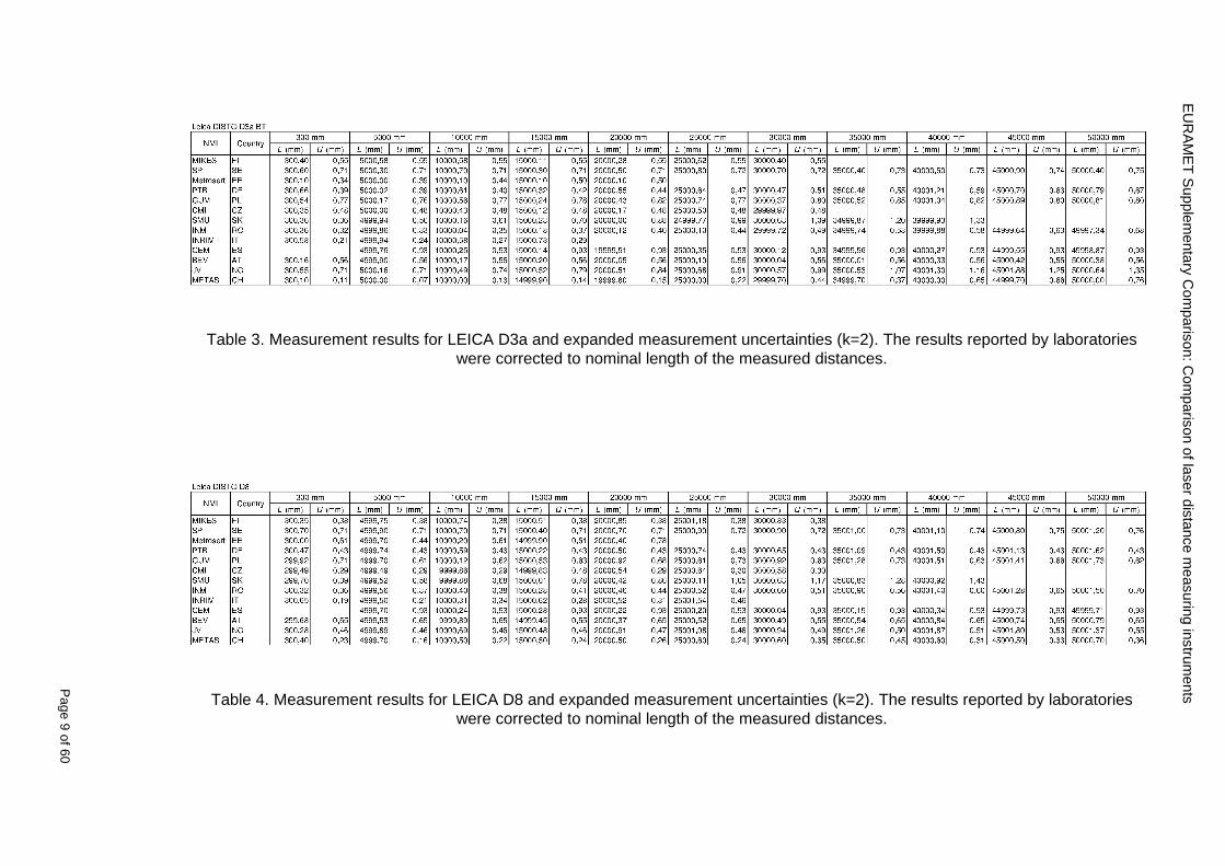
EU
RA
ME
T S
upplementary C
omparison C
omparison of laser distance m
easuring instruments
P
age 9 of 60
Table 3 Measurement results for LEICA D3a and expanded measurement uncertainties (k=2) The results reported by laboratories were corrected to nominal length of the measured distances
Table 4 Measurement results for LEICA D8 and expanded measurement uncertainties (k=2) The results reported by laboratories were corrected to nominal length of the measured distances
EURAMET Supplementary Comparison Comparison of laser distance measuring instruments
Page 10 of 60
7 Measurement uncertainties The participants were asked to report detailed measurements uncertainty budgets evaluated according to the ISO Guide In table 5 the majority of the contributions are summarized as they had been reported by the participants
Tab
le 5
Sum
mar
y of
the
mos
t fr
eque
ntly
rep
orte
d m
easu
rem
ents
unc
erta
inty
con
trib
utio
ns in
mm
tak
en fr
om
unce
rtai
nty
budg
ets
repo
rted
by
the
part
icip
atin
g la
bora
torie
s
EURAMET Supplementary Comparison Comparison of laser distance measuring instruments
Page 11 of 60
8 Stability of the EDMs
Repeatability measurements showed that in the short period (less than 60 min) indications of the EDMs did not reveal any drift Large differences (~ 15 mm) were also noted between the mean values of the subsequent measurement series performed within 48 hours Considering this effect in uncertainty budget and on the basis of measurements made at the beginning in the middle and at the end of the comparison one cannot determine the drift of the results
Stability measurements Bosch DLE 50
-25
-20
-15
-10
-05
00
05
10
15
20
25
03 5 10 15 20 25 30 35 40 45 50
Length m
Dev
iatio
n fro
m m
ean
m
m
2011 02
2011 08
2012 09
Stability measurements Bosch GLM150
-15
-10
-05
00
05
10
15
03 5 10 15 20 25 30 35 40 45 50
Length m
Dev
iatio
n fr
om m
ean
m
m
2011 02
2011 08
2012 09
Stability measurements Leica DISTO D3a BT
-15
-10
-05
00
05
10
15
03 5 10 15 20 25 30 35 40 45 50
Length m
Dev
iatio
n fro
m m
ean
m
m
2011 02
2011 08
2012 09
Stability measurements Leica DISTO D8
-10
-08
-06
-04
-02
00
02
04
06
08
10
03 5 10 15 20 25 30 35 40 45 50
Length m
Dev
iatio
n fro
m m
ean
mm
2011 02
2011 08
2012 09
Fig 1 Measurements of the pilot laboratory monitoring the stability of all four EDMs at each of the measuring distances bounded by the expanded measurements uncertainty (for k=2 dashed line) The solid curves represent deviation from the arithmetic mean of the three measurements The test of the stability of the EDMs showed significant changes in the mean results in timescale months or even days A detailed analysis of the observed problems will be presented by way of example with Leica DISTO D8 and for a 10 m distance This EDM has been chosen because it is theoretically the best of the compared models with resolution of 01 mm over whole range Depending on the measured distance the EDM is characterized by some measurement uncertainty Typically the standard deviation increases along the distance Distance of 10 m was selected to minimize the impact of the uncertainty on a single measurement The more the distance from the target increases the weaker the reflected signal becomes and the more the uncertainty of a single measurement increases while for very short distances the reflected signal is so strong that it can also have a negative impact on the results
Stability over few minutes time interval
The studies performed showed that deviations from expected value are well characterized by normal distribution Results of those studies are presented in the figure below Probability density of deviations from expected value for Leica D8 for 10 m is consistent with a normal
EURAMET Supplementary Comparison Comparison of laser distance measuring instruments
Page 12 of 60
distribution with standard deviation s = 019 (blue marks ndash experimental red line ndash fitted model)
-10 -9 -8 -7 -6 -5 -4 -3 -2 -1 0 1 2 3 4 5 6 7 8 9 10
dx 01 mm
Fig 2 Distribution of results over few minutes time interval
Stability over tens of minutes time interval
Several series of measurements were made with a duration from 15 minutes to 30 minutes at a constant distance and under constant measurement conditions For most of the series changes in the average value of indications of EDMs have been observed at the level of about 02 mm However for one of the series change exceeds 05 mm (see figure below) This value leads to u = 015 mm
-06
-04
-02
0
02
04
06
08
1
0 5 10 15 20 25 30
t min
dx
mm
Fig 3 Stability of results over tens of minutes time interval
Stability in the timescale of days and months
The measurements were performed in three series of measurements over an interval of a few days The cycle of measurements was repeated twice within a few months The first three measuring series were carried out in February 2011 then in August 2011 and the last one in September 2012
In the figure below the standard deviations of individual measurements of distance are shown with error bars The dashed lines represent minimum and maximum values of individual measurements in the series of measurements
EURAMET Supplementary Comparison Comparison of laser distance measuring instruments
Page 13 of 60
Leica DISTO D8 (interval 010 m)
-06
-04
-02
00
02
04
06
08
10
12
14
series
devi
atio
n fro
m n
omin
al le
ngth
m
m
Fig 4 Results of all series of measurements for Leica DISTO D8 for a distance of 10 m
Having analyzed the graph one can see that the maximum and minimum values in each series performed at an interval of several months do not overlap The mean value in one of the series is not even in a range limited by minimum and maximum for the other series
Such a large differences between the average values appear over a time scale longer than few days This means that the laboratory couldnrsquot observe this variability when briefly examining the instrument
In the figure below probability density of all results from all measurement series was presented
-10 -5 0 5 10 15 20
dx 01 mm
Fig 5 Distribution of all results from all measurement series
Continuous red curve represents the sum of the theoretical normal distributions for each series of measurements Theoretical curve is consistent with the observed distribution
max (x1x9)
min(x1x9)
di
201102 201108 201209
EURAMET Supplementary Comparison Comparison of laser distance measuring instruments
Page 14 of 60
Estimation of uncertainty of artifact
The reproducibility of EDM is affected by random changes of mean values in time scale of days To determine di for a given EDM and a given distance the results from all nine series of measurements )( 91 xx were used
)min()max( 9191 xxxxdi minus=
where i is an index of measurement distance
Set of eleven di was determined for each EDM The figure below presents those results
0
05
1
15
2
25
0 5 10 15 20 25 30 35 40 45 50
Length m
d i
mm
DLE 50
GLM 150
D3s BT
Leica D8
Fig 6 di values for all distances for each EDM
The value of di varies widely This is especially noticeable in Bosh DLE 50 where for the neighboring distances the di values can differ by several times Each EDM is characterized by a different trend
The model assumes that long-term stability is characterized by rectangular distribution with domain described by maximal di and expected value estimated based on all of the measurements Dispersion of individual measurements (short-term stability) is described by normal distribution
The max value of di was used to estimate uncertainty u(dart) related to random changes of EDM results In order to disentangle u(dart) one should try to subtract the observed short term stability from max(di) and influences of the different alignments like zero point uzero cosine error ucos and parallelism uparal [3]
( ) 22cos
2
2
art2
32
)max(paralzero
i uuud
du minusminusminus
=
In the case of Leica DISTO D8 we obtain max(di) = 1133 which corresponds to u(dart) = 0324 mm
Table below contains values of u(dart) estimated for all the four EDMs
EURAMET Supplementary Comparison Comparison of laser distance measuring instruments
Page 15 of 60
Table 6 Values of u(dart) for all the four EDMs
EDM u(dart) (mm)
Bosch DLE 50 0308
Bosch GLM 150 0197
Leica DISTO D3a BT 0149
Leica DISTO D8 0324
Additional stability test of EDMs
The suspected main factors responsible for the change of EDMs indications are 1) Effects of electronics ndash resulting from unstable operation of the EDM 2) Effects of mechanics ndash impact of transport of the EDM between laboratories 3) Effects of geometry ndash alignment repeatability of the EDM during measurements
Two additional experiments were conducted in order to determine which factors have the greatest impact on the results Leica DISTO D3a BT was used for these tests
a) Static test
During the measurements the EDM was immobilized on a bench Measurements were made at a distance of 10 m in a controlled environment The measurement results are presented in the figure below
-04
-03
-02
-01
00
01
02
03
04
1 2 3 4 5 6 7 8 9 10 11 12 13 14 15 16 17 18 19 20
measure
dx
mm
Fig 7 Static stability test results
Each point represents the mean value of 15-20 measurements This test covers about 6 hours of EDM work The standard deviation is s = 009 mm
b) Dynamic test
Measurements were made at a distance of 10 m in a controlled environment After each series of measurements the EDM was removed from the bench shaken and squeezed The aim was to simulate the conditions during transportation This test covers about 6 hours of EDM work Measurement results are presented in the figure below
EURAMET Supplementary Comparison Comparison of laser distance measuring instruments
Page 16 of 60
-04
-03
-02
-01
00
01
02
03
04
1 2 3 4 5 6 7 8 9
measure
dx
mm
Fig 8 Dynamic stability test results
The standard deviation for this test is s = 015 mm and is greater than in the static test
The average standard deviation of three measurement series was estimated using the data from the comparison The value s = 009 mm is similar to the result in the static test
The estimated uncertainty associated with the artifact for this EDM is uart = 015 mm (see table above) The same value u = 015 mm was estimated from the stability test in the scale of tens of minutes Both values are close to the value of standard deviation for the dynamic test
These results may lead to the conclusion that the level of the effects of electronics mechanics and geometry have a similar impact on the long-term stability Due to this fact it is difficult to identify which of these factors has the greatest impact on the observed measurement results
EURAMET Supplementary Comparison Comparison of laser distance measuring instruments
Page 17 of 60
9 Reference values The standard approach is to use weighted mean for determining the reference value xref [12] This is calculated by the mean of all measurement values xi weighted by the inverse square of the standard uncertainties u(xi) associated with the measurements and using these values the largest consistent subset of the sample is determined However checking the consistency of the sample without taking into account the uncertainty associated with the artifact leads to erroneous recognition of the consistent subset We propose to add uart to the uncertainty of each laboratory at the beginning of the calculation
( ) )()( 222iartic xuduxu +=
Thereby the uncertainty associated with the artifact will be taken into account during the consistency check
sum
sum
=
==n
i ic
n
i ic
i
ref
xu
xu
x
x
12
12
)(
1
)(
The pilot laboratory contributed only by its first measurements to the reference values The weighted mean approach requires the individual uncertainties from the laboratories to be estimated according to a common approach (as they should be since all participants were requested to estimate the uncertainties according to the ISO Guide) The standard uncertainty u(xref) of the reference value is calculated by combining the individual uncertainties
sum=
=n
i ic
ref
xu
xu
12
2
)(
1
1)(
The χ2 test was applied in order to estimate xref from the largest consistent subset [1]
EURAMET Supplementary Comparison Comparison of laser distance measuring instruments
Page 18 of 60
Table 7 Reference values and associated standard uncertainties based on weighted mean
Distance Bosch DLE 50 Bosch GLM 150 Leica DISTO D3a BT
Leica DISTO D8
mm xref u(xref) xref u(xref) xref u(xref) xref u(xref)
300 299694 0138 300475 0084 300353 0071 300177 0113
5000 4999900 0139 4999774 0090 5000020 0074 4999659 0111
10000 10000041 0146 9999776 0096 10000285 0077 10000336 0114
15000 14999945 0154 14999781 0120 15000176 0080 15000258 0117
20000 19999804 0175 19999423 0124 20000112 0086 20000581 0118
25000 24999955 0186 24999526 0128 25000321 0094 25000754 0124
30000 29999586 0193 29999956 0138 30000140 0103 30000675 0129
35000 34999779 0235 35000051 0156 35000022 0119 35000844 0153
40000 40000185 0279 40000250 0159 40000476 0132 40001167 0151
45000 44999576 0315 45000208 0165 45000391 0155 45000974 0156
50000 49999983 0324 50000344 0169 50000319 0156 50001137 0157
EURAMET Supplementary Comparison Comparison of laser distance measuring instruments
Page 19 of 60
10 Deviations from reference values The following figures show results from NMIs for all of the distances Reference value is represented by a bold black line
Bosch DLE 50
-30
-25
-20
-15
-10
-05
00
05
10
15
20
25
30
0 5 10 15 20 25 30 35 40 45 50 55
Length m
Dev
iatio
n fr
om n
omin
al le
ngth
m
m
MIKES
SP
Metrosert
PTB
CMI
SMU
INM
INRIM
CEM
BEV
JV
METAS
GUM
Ref
Bosch GLM 150
-20
-15
-10
-05
00
05
10
15
20
0 5 10 15 20 25 30 35 40 45 50 55
Length m
Dev
iatio
n fr
om n
omin
al le
ngth
m
m
MIKES
SP
Metrosert
PTB
CMI
SMU
INM
INRIM
CEM
BEV
JV
METAS
GUM
Ref
Fig 9 Deviations from reference values
EURAMET Supplementary Comparison Comparison of laser distance measuring instruments
Page 20 of 60
Leica DISTO D3a BT
-20
-15
-10
-05
00
05
10
15
20
0 5 10 15 20 25 30 35 40 45 50 55
Length m
Dev
iatio
n fr
om n
omin
al le
ngth
m
m
MIKES
SP
Metrosert
PTB
CMI
SMU
INM
INRIM
CEM
BEV
JV
METAS
GUM
Ref
Leica DISTO D8
-20
-15
-10
-05
00
05
10
15
20
0 5 10 15 20 25 30 35 40 45 50 55
Length m
Dev
iatio
n fr
om n
omin
al le
ngth
m
m
MIKES
SP
Metrosert
PTB
CMI
SMU
INM
INRIM
CEM
BEV
JV
METAS
GUM
Ref
Fig 9 Deviations from reference values (continued)
The deviations Di from reference value xref are calculated by
refxxD ii minus=
For calculating the expanded uncertainty of these deviations U(Di) the corresponding uncertainties u(xi) and u(xref) cannot simply be geometrically added because the values xi and xref are correlated Due to the random changes described in section 6 uncertainty u(dart) was added [2] It can be shown that the expanded uncertainty U(Di) is given by
)()()(961)( art2
ref22 duxuxuDU ii +minus=
when xi belongs to the largest consistent subset and
)()()(961)( art2
ref22 duxuxuDU ii ++=
EURAMET Supplementary Comparison Comparison of laser distance measuring instruments
Page 21 of 60
otherwise The deviations from the reference values are given in various figures and tables below The uncertainty bars in the figures correspond to the expanded uncertainties U(Di) (k = 196)
Fig 10 Deviations from reference values
EURAMET Supplementary Comparison Comparison of laser distance measuring instruments
Page 22 of 60
Fig 10 Deviations from reference values (continued)
EURAMET Supplementary Comparison Comparison of laser distance measuring instruments
Page 23 of 60
Fig 10 Deviations from reference values (continued)
EURAMET Supplementary Comparison Comparison of laser distance measuring instruments
Page 24 of 60
Fig 10 Deviations from reference values (continued)
EURAMET Supplementary Comparison Comparison of laser distance measuring instruments
Page 25 of 60
Fig 10 Deviations from reference values (continued)
EURAMET Supplementary Comparison Comparison of laser distance measuring instruments
Page 26 of 60
Fig 10 Deviations from reference values (continued)
EURAMET Supplementary Comparison Comparison of laser distance measuring instruments
Page 27 of 60
Fig 10 Deviations from reference values (continued)
EURAMET Supplementary Comparison Comparison of laser distance measuring instruments
Page 28 of 60
Fig 10 Deviations from reference values (continued)
EU
RA
ME
T S
upplementary C
omparison C
omparison of laser distance m
easuring instruments
P
age 29 of 60
Table 8 Deviations from the reference value (given at the top of the table) and expanded uncertainties (k=196) of such deviations for BOSCH DLE 50
Table 9 Deviations from the reference value (given at the top of the table) and expanded uncertainties (k=196) of such deviations for BOSCH GLM 150
EU
RA
ME
T S
upplementary C
omparison C
omparison of laser distance m
easuring instruments
P
age 30 of 60
Table 10 Deviations from the reference value (given at the top of the table) and expanded uncertainties (k=196) of such deviations for Leica DISTO D3a BT
Table 11 Deviations from the reference value (given at the top of the table) and expanded uncertainties (k=196) of such deviations for Leica DISTO D8
EURAMET Supplementary Comparison Comparison of laser distance measuring instruments
Page 31 of 60
11 En Tables Results with En gt 1 are marked with red color in Tables below En values are calculated by Di U(Di) with Di and U(Di) as given on page 19
Table 12 BOSCH DLE50
Lab Distance (mm) 300 5000 10000 15000 20000 25000 30000 35000 40000 45000 50000
MIKES -058 017 -019 -023 035 -002 -096 SP 020 019 006 005 009 059 064 037 028 097 001
Metrosert -030 -031 -003 018 032 PTB 001 029 022 -006 011 -036 001 -023 -075 -083 001 GUM -033 -005 -018 -009 000 006 017 005 -026 -028 019 CMI -003 020 -009 004 005 -022 028 SMU 006 -049 -034 -023 -017 -057 051 039 021 INM 032 031 037 006 020 005 -079 -119 -272 -260 -269
INRIM 025 -013 000 096 CEM -032 -022 -041 -039 -004 -038 080 001 -094 -047 BEV -010 007 000 -001 008 -011 037 013 -001 008 -001 JV -019 -016 025 -055 055 060 068 163 122 060 089
METAS 038 012 -005 007 -107 004 -024 002 -070 037 -052
Table 13 BOSCH GLM150
Lab Distance (mm) 300 5000 10000 15000 20000 25000 30000 35000 40000 45000 50000
MIKES 005 -002 019 018 027 019 062 SP 003 068 029 023 051 008 015 016 -005 -001 038
Metrosert -061 -011 -022 -021 -003 PTB 066 074 062 062 034 053 047 048 047 091 064 GUM -007 -014 007 -018 000 023 020 033 014 032 038 CMI -057 -032 -030 -064 -050 -047 000 SMU 023 -024 -060 012 062 001 -003 050 047 INM -022 017 -003 002 -003 054 005 -006 016 -022 -055
INRIM 079 -052 -050 -026 -034 -042 CEM 002 002 -034 -020 -029 -077 -077 -077 -074 -104 BEV -004 -002 -007 010 -042 -042 -029 -011 -028 -022 -030 JV 003 015 040 011 -020 021 -029 -005 028 036 058
METAS -047 -020 005 002 -012 -033 -054 -065 -053 -082 -040
Table 14 Leica DISTO D3a BT
Lab Distance (mm) 300 5000 10000 15000 20000 25000 30000 35000 40000 45000 50000
MIKES 008 094 050 -011 028 051 045 SP 033 038 056 017 053 065 076 051 017 071 011
Metrosert -060 -004 -037 -014 -002 PTB 067 000 070 030 089 062 061 081 124 050 072 GUM 023 019 035 008 038 053 029 058 070 064 063 CMI -001 -004 027 -011 011 034 -033 SMU 002 -013 -019 007 -013 -055 045 -013 -042 INM 002 -039 -058 001 002 -045 -080 -051 -102 -101 -378
INRIM 070 -020 063 101 CEM -028 -004 -004 -064 003 -002 -050 -022 -093 -160 BEV -032 -019 -019 004 -011 -037 -017 -002 -025 005 012 JV 027 019 027 042 046 039 043 048 072 115 024
METAS -091 -008 -102 -098 -111 -103 -092 -080 -073 -108 -043
EURAMET Supplementary Comparison Comparison of laser distance measuring instruments
Page 32 of 60
Table 15 Leica DISTO D8
Lab Distance (mm) 300 5000 10000 15000 20000 25000 30000 35000 40000 45000 50000
MIKES 025 013 058 036 038 061 022 SP 057 026 040 016 013 016 025 017 -007 -019 007
Metrosert -021 006 -016 -043 -019 PTB 040 011 035 -005 -011 -002 -004 035 047 022 069 GUM -028 005 -025 031 039 -015 029 048 041 052 072 CMI -104 -026 -072 -057 -006 -017 -015 SMU -067 -017 -051 -026 -016 -054 -004 -001 -016 INM 021 -014 009 003 -017 -031 -010 007 029 036 041
INRIM 076 -024 -004 047 -007 083 CEM 004 -009 002 -033 -051 -059 -097 -077 -116 -134 BEV -057 -014 -051 -093 -024 -027 -021 -036 -038 -028 -041 JV 014 031 047 030 044 043 035 056 093 108 030
METAS 035 007 026 038 -013 -024 -011 -048 -089 -074 -066
12 Conclusions It was the first comparison of EDMs For most of the laboratories it was an important opportunity to validate their measurement instrumentation and procedure It allowed to become aware of potential problems and to take corrective actions in changing the procedure
For the evaluation of the reference value the weighted mean approach has been chosen although the consistency check according to procedure A of Ref [1] failed in many cases A more complicated procedure for the evaluation of the reference value was proposed which slightly changes the uncertainty of the reference value
In total there were 23 En values larger than 1 This represents 47 of the full set of 482 results It is less than the 5 of possible values being out of the expanded uncertainty of the reference value for k=2
The uncertainty of the results mainly comes from the uncertainty of the reproducibility It is difficult to distinguish between Labrsquos calibration and measurement capability
The comparison shows a global compliance with declared CMCs independently of whether some participant can have a high percentage of values not compliant with its CMC due to the influence of the artifact and the estimation of its uncertainty
13 References [1] M G Cox The evaluation of key comparison data Metrologia 39 589 ndash 595 (2002)
[2] R Thalmann EUROMET 677 ndash Steel Tape Measures Final report (2004)
[3] F Pollinger personal communication
EURAMET Supplementary Comparison Comparison of laser distance measuring instruments
Page 33 of 60
Appendix 1 Description of the measurement equipmen t as reported by the laboratories
A11 MIKES Finland
Short description of measurement bench
MIKES interferometric bench is situated in an underground laboratory with air temperature and humidity control Typically air temperature is 20 plusmn 01 degC and humidity 45 plusmn 2 RH The linear guide on the top of the concrete beam comprises two parallel round shafts with adjustable fixtures every 1 m A carriage with ball bush bearings is moved along the rail and location of it is measured with reference interferometer HP-5529A Temperature of air is measured with 6 pt100 sensors and Keithley 2010 multimetre with 4-wire resistance mode Air pressure and humidity are measured with Vaisala PTU200 Updated Edleacuten equation by Boumlnsch amp Potulski is used for calculation of refractive index of air
For EDM calibration on the other end than laser interferometer is a fixed reference plate which is adjusted perpendicular to the laser beam Next to the reference plate is an adjustable base for EDM instrument with which it can be adjusted to point parallel and coincident with measurement arm of the interferometer A target plate adjusted perpendicular to laser beam is fixed to the carriage The calibration followed Abbe principle with some millimetre uncertainty in offset adjustment
First reference interferometer is set to zero when the target plate and reference plate are in contact then EDM is positioned and adjusted in its base The rear surface of the EDM is also slightly pressed against reference surface behind it Then the readings from both instruments are collected at selected locations For this calibration there is no fine adjustment of the target position so there are typically deviations of up to few millimetres from nominal locations Results are averages of 3-4 measurements
Additional remarks
The CMC entry MIKES has for EDM calibrations is based on calibration of length scales of high quality total stations and laser trackers This type of EDMs used in this comparison are not accurate enough for truly testing of MIKES calibration measurement capability
EURAMET Supplementary Comparison Comparison of laser distance measuring instruments
Page 34 of 60
A12 SP Sweden
Short description of measurement bench
The bench consists of a simple aluminium Uminusshaped profile with polished steel pins acting as supports for the tape The bench is a little over 50 m long and works as support for the reference tape and the calibrated EDMs simultaneously
Length measurement instrument
Comparison with reference steel tape
Temperature measurement system number and location of sensors
The tape temperature is continuously registered in 6 points equally distributed along the bench The air temperature is monitored during the measurements but not used for corrections
Additional remarks
The EDM support is placed approximately 2 cm vertically above the tape No visual aid is used
EURAMET Supplementary Comparison Comparison of laser distance measuring instruments
Page 35 of 60
A13 AS Metrosert Estonia
Short description of measurement bench
The 21-m bench is located in the designated corridor-like laboratory room The lab is air-conditioned and the stability of temperature is typically plusmn05 ordmC There are three humidity and temperature sensors in room for stability and gradient monitoring
Two stainless steel rails running in parallel are made of 3-m long rods The rails lay without fixed attachment on metal supports which are mounted on concrete base The base rests on pillars made of bricks
Length measurement instrument
Laser-interferometer system Renishaw ML10 was used as length measurement instrument
Laser interferometer gets temperature humidity and pressure data from itrsquos own measurement system EC10
Additional remarks
Due to the length of the bench only measurements up to 20 m could be made Five measurement series were made with each EDM
EURAMET Supplementary Comparison Comparison of laser distance measuring instruments
Page 36 of 60
A14 PTB Germany
Short description of measurement bench
The measurements were performed on the 50 m geodetic base of the PTB The comparator consists of a 50 m rail The laboratory is equipped with a network of 21 temperature sensors spaced by 25 m along the bench As depicted in fig 1 the EDM is mounted at one end of the comparator the reflector is fixed vertically on the carriage A large retroreflector is mounted approximately 150 mm below the EDM reflector on the carriage reflecting the beam of the reference interferometer The deviation of the length due to tilting carriage (Abbe error) has been investigated along the bench by comparison of two interferometers It remains smaller than 100 microm The distance of the first position of 300 mm with respect to the back side of the EDM is determined by a gauge block of 300 mm length and a thickness of 10 mm This procedure is depicted for one of the comparison standards in figure 2
For the calibration the desired positions are programmed After the carriage reaches a measurement position the operator waits for another 30 s for the carriage to settle In control experiments the remaining movement between positioning and measurement remained smaller than 2 microm The operator then activates the measurement of the EDM reads the indicated position and writes it down The procedure is repeated for twelve times at every position the mean of the 12 measurements represents the ldquoindicated distance by the EDMrdquo All measurements of a single run at one position are performed within approximately one minute The complete measurement was repeated for four times
Length measurement instrument
The reference length is determined by a frequency-calibrated laser interferometer (Agilent 5519A) The reference interferometer is set up in Michelson geometry the signals being digitalised by a Heidenhain IK 121 card The index of refraction is determined by the external weather station of the geodetic base consisting of 21 Pt-100 temperature sensors spaced 25 m along the bench two humidity sensors (Testo 650) and two pressure sensors (Setra 370 and DPI 141) The environmental parameters are used to determine the index of refraction for the reference measurement deploying the modification of the Edleacuten equation by Boumlnsch and Potulski
EURAMET Supplementary Comparison Comparison of laser distance measuring instruments
Page 37 of 60
A15 CMI Czech Republic
Description of measurement bench
The EDMs were measured on 30 m long measuring bench equipped by laser interferometer (LI) Renishaw ML10 (pic 1 and 2) calibrated traceable to national standard of length and quantities of environmental sensors The target plate and retroreflector of the LI were fixed on a moving part of the bench and each EDM was fixed in horizontal position by clamps (pic 3) LI and EDM are placed on opposite ends of bench the Abbe offset was lt10 mm for some of them and lt50mm for all The value of LI was reset (to zero) at position corresponding to the rear of the EDM (using 3D measuring arm FARO Quantum with uncertainty about 27microm) The perpendicularities of the EDM stop as well as target plate to the beam were also checked by FARO) Each EDM was 3x replaced and aligned the measurement (reading) was repeated 6 times for each alignment and position the mean value of these 3x6 measurements is stated in tables with results The uncertainty claimed covers the statistical uncertainty of single readings Only in case of Leica D8 (the best performing EDM in this comparison) we state also the uncertainty corresponding to the mean of 6 readings in last column (this uncertainty is smaller and better illustrates our CMC)
Length measurement instrument
- Laser interferometer Renishaw - Laser 633 nm Type ML10 - Compensator EC10 - 3D measuring arm FARO Quantum - 3D measuring arm FARO Quantum
EURAMET Supplementary Comparison Comparison of laser distance measuring instruments
Page 38 of 60
A16 SMU Slovakia
Short description of measurement bench
No bench is available at the SMU the measurements are being carried out in the underground corridor of the laboratory building with length of 428 m
The 50 m steel measuring tape KINEX was used as the reference laid on the floor and pulled by the force 50 N (the same force as had been applied during its calibration at the SMU) The calibration of reference tape was done at the SMU using ULM3m Zeiss with laser interferometer Agilent 5529 B (ie per 3 m parts)
Three mercury thermometers with the resolution of 01 degC were used along the measurement path each of them laid onto the tape and located at 667 m 1990 m (instead of 20 m because of this was one of measuring points) and 333 m respectively Each of them thus corresponded approximately to one third of the measured steel tape section
Regarding the 03 m measuring point the ULM3m Zeiss length measuring machine was used with the 300 mm gauge block as the reference
Length measurement instrument
We used our own target plate being fixed perpendicularly (within uncertainty stated) to the construction equipped with nonius and the camera holder transported manually along the steel tape The second construction was fixed to the tape by such a way that zero line of the tape corresponded to the rear of EDM (within uncertainty stated)
The position of the target is read on the monitor and 20 repeated readings of the EDM data took place in each measuring point (multiples of 5 m up to 40 m)
Concerning 03 m the 300 mm gauge block was fit between the target plate and the construction with EDM The distance of the EDM rear from the target plate corresponded to the length of gauge block (within uncertainty stated)
Additional remarks
The identical measurement method was used as we use to do within our calibration service although the results reporting is different ndash we provide the regression line calculated from the measurement of irregularly distributed points and corresponding uncertainty (k = 2) in the form of [a bL] mm (ie the same coefficients for each length in the range (0 ndash 42) m)
SMU hasnrsquot got this category in CMC tables
EURAMET Supplementary Comparison Comparison of laser distance measuring instruments
Page 39 of 60
A17 INM Romania
Short description of measurement bench
Geodesic base located in the basement of the laboratory with nominal length equal to 50 m having a mobile carriage thet support both laser He-Ne retroreflector and the target of the laser distance measuring instrument in the front of geodesic base exists a support where are aligned both laser interferometer and the laser distance measuring instruments
Length measurement instrument
Laser interferometer type Hewlett Packard model 5526 A with nominal length equal to 50 m resolution 0001 mm
U = 02 microm +0510-6L
Additional remarks
During the measurements the maximum gradient of temperature was equal to 05 degC
EURAMET Supplementary Comparison Comparison of laser distance measuring instruments
Page 40 of 60
A18 INRIM Italy
Short description of measurement bench
The facility for long distance measurements is located in a corridor of the gallery devoted to dimensional metrology The structure consists in a 28 m long rail fixed to a series of pillars which rest directly on the ground released from the vibrations of floor and wall The measuring system is based on a heterodyne interferometer whose mobile arm consists of a hollow retro-reflector mounted on a structure that can run along the rail so-called carriage A photograph of the facility is presented in Fig1
The carriage is moved by a micro-step motor the motor driver receives a digital pulse and converts it into an electrical pulse to run the motor Each pulse causes a rotation of the motor shaft of one step which amounts to 11000 of a complete revolution of the shaft If the pulse frequency increases the rotation becomes continuous with a speed that is directly proportional to the pulse frequency The speed ranges between few microms up to 27 ms with a resolution of 03 microms
Since the carriage must move back and forth automatically for a distance of almost 30 m a remote control to send pulses to the motor driver was implemented It consists of two parts a radio command which allows to set some general parameters of the carriage movement such as the movement direction and mode of travel (slow or fast) and a fast command which is performed by an amplitude modulated laser beam placed at the beginning of the track oriented towards the carriage A photo detector placed above the carriage receives the modulated laser beam which is transformed into pulses to be sent to the driver of the motor The modulation of the laser beam is implemented by a LabView program that controls a digital output of the data acquisition device
Length measurement instrument
The length measurement instrument is based on a heterodyne incremental interferometer The main beam of the interferometer with frequency f1 is generated by a frequency stabilized
EURAMET Supplementary Comparison Comparison of laser distance measuring instruments
Page 41 of 60
He-Ne laser calibrated with respect to the INRIM length standard and sent to the measurement arm the second beam is a portion of the first one diffracted by an acousto-optic modulator (AOM) with frequency f2 = f1 + 80 MHz The reference detector acquires the beat note signal at 80 MHz while the measurement detector acquires a signal at 80 MHz whose phase is varied due to the displacement of the retro-reflector moving on the rail In figure 2 the optical design of the interferometer is presented
Two different measuring techniques have been implemented
1 the ldquophase measuringrdquo technique based on fringes counting with a relative uncertainty of 5middot10-7 but limited at the maximum carriage speed of 3 cms
2 the ldquoDoppler frequency measurementrdquo technique for higher carriage speed based on the measurement of the Doppler frequency shift while the carriage runs
The second technique was validated by means of the comparison with the first technique at low speed with an agreement of the order of 3middot10-6 hence the Doppler frequency method could be considered validated within 01 mm over the whole rail path with the advantage of reducing the time needed to cover long distances so it was used for the EDM comparison
In order to obtain the distance covered by the carriage according to technique 2 the Doppler frequency is measured by a commercial high-performance counter (a Pendulum CNT-90) without dead time based on time stamping then it is converted in speed and integrated over time according to the following formula
( ) ( )int minus=minus= tffn
dtn
ffdairair
λλ
2
1
2
1
where d is the distance covered by the carriage f is the frequency of the measuring signal with the carriage at rest frsquo the frequency of the measuring signal with the carriage moving λi
is the wavelength of the laser in vacuum n - air is the air refractive index and ti is the integration time The difference frsquo-f is just the Doppler frequency due to the moving carriage
The time interval measurement resolution of the instrument is 100 ps and the time base is
EURAMET Supplementary Comparison Comparison of laser distance measuring instruments
Page 42 of 60
connected to the INRIM UTC so that the measurements of the Doppler frequency and the integration time are extremely accurate The environmental parameters such as air temperature atmospheric pressure partial pressure of water were monitored during the measurement process in order to calculate the value of air refractive index according to the Edlenrsquos formula
Comparison set-up
The different technical solutions adopted for the EDMs and for the target plate positioning are discussed in this paragraph and sketched in figure 3
Fig 3 picture of the EDM and target positioning area
Target plate positioning
In order to use the provided target plate an ad-hoc mounting was manufactured at INRIM it consists in a sort of picture frame made in aluminum which slightly clamps the target folded in half and gives it the necessary stiffness to be a reproducible target The upper part of the frame is L-shaped and allows it to be fixed to the carriage structure by means of two screws The rear part of the target mounting is depicted in figure 4 The target mounting was considered necessary because of the poor stiffness and planarity of the plastic target With the aluminium frame a planarity better than 01 mm was guaranteed The target plate is placed few centimetres next to the retro-reflector and normal to the interferometer beam axis since the EDM laser should be as close and parallel as possible to the reference beam
EURAMET Supplementary Comparison Comparison of laser distance measuring instruments
Page 43 of 60
Fig 4 picture of the rear part of the target plate mounting
EDMsrsquo positioning
The EDMs are placed on a cradle-like platform which is able to adjust the inclination of the EDM along the longitudinal axis (pitch angle) The platform height allows the EDMs to be at approx the same height as the interferometer beam A crucial role was played by the stop-wall placed behind the platform since it represents the ldquozero pointrdquo for all the length measurement Hence a particular effort was devoted to align the stop-wall so that it was normal to the interferometer beam axis and parallel to the target plate
Fig 5 detail of EDMsrsquo positioning the cradle-like platform and the stop-wall are well visible
EURAMET Supplementary Comparison Comparison of laser distance measuring instruments
Page 44 of 60
Target and stop-wall alignment
In order to have the stop-wall parallel to the target plate and normal to the interferometer beam axis the following procedure has been used
1) the stop-wall and the target plate were roughly placed trying to set them parallel and normal to the rail by eye (ie within few millimeters)
2) in order to check if the target was normal to the rail one EDM was positioned on the platform the pitch and yaw angles of the EDM were adjusted by observing the position of the EDM laser spot on the target plate when the target is moved along the rail fixed position means laser beam parallel to the carriage movement Then the target was moved until the end of the rail and a thin mirror was kept in contact with it hence observing the EDM laser reflected by the mirror it was possible to adjust the target tilt acting on the screws until the laser beam is reflected back to the source
3) finally in order to check the parallelism between the stop-wall and the target a tool made by a laser pointing orthogonally to its base was used the base was leant against the stop-wall and the laser was centered on the target when the target is near then the target was moved until the end of the rail hence observing the spot of the laser on the target it was possible to adjust the stop-wall orientation
The residual misalignment errors which we were not able to eliminate were kept into account in the uncertainty budget
Measurement of the first 30 cm
Due to the geometry of our set-up it was not possible to perform the first point of measurement by means of the interferometer indeed the carriage (hence the target) is not able to go in contact with the stop-wall
Fig 6 measurement of the first 30 cm the ruler touching the stop-wall and the target and the mechanical probe (in the back) touching the carriage are visible
EURAMET Supplementary Comparison Comparison of laser distance measuring instruments
Page 45 of 60
So a ruler made of aluminum with rounded ends and nominal length equal to 30 cm was adopted to set the distance between the target plate and the stop-wall for the first point of measurement as it is shown in figure 6 The ruler whose length was measured by a CMM machine was inserted between the target and the stop-wall leaning against the latter and the carriage was carefully moved towards the stop-wall until the target lightly touched the ruler A mechanical probe that touches the carriage structure when carriage is in the ldquo30 cmrdquo position was used as a reference measurement to check the repeatability of this distance after each measurement set
Fig 7 detail of the mechanical probe touching the carriage
Environmental parameters
The environmental parameters such as air temperature atmospheric pressure and humidity were monitored during the whole measurement process in order to calculate the value of air refractive index according to the Edlenrsquos formula
Among these parameters the temperature distribution along the mobile arm of the interferometer was our main concern mainly for two reasons
1 the temperature control of the gallery was not perfectly working during the measurement period so temperature drifts had to be monitored
2 longitudinal temperature gradients due to non uniform heating and to the presence of electronic instruments were pretty high
To the purpose 14 thermometers were uniformly dislocated along the rail and automatically recorded for all the measurement period Both temporal drifts and gradients along the path have been taken in account in the uncertainty budget In any case maximum temperature differences along the rail are within 1 degC In fig 8 an extract from the acquisition file is shown
Unfortunately the air conditioning system did not work well during the measurement campaign hence the measurements were performed at a mean temperature of 209 degC
EURAMET Supplementary Comparison Comparison of laser distance measuring instruments
Page 46 of 60
Fig 8 each curve represents the temperature distribution along the rail during the measurements campaign
Carriage waving
Since the rail is not perfectly straight and the measurement laser is not coincident with the measurement beam the Abbegrave error due to waving of the target must be considered A quantitative measurement and a qualitative measurement were carried out With an electronic level placed on the carriage the straightness on the vertical plane has been mapped with a half meter resolution (the data are reported in fig 9) With a laser placed on the carriage the horizontal and vertical waving are qualitatively compared by looking at the movements of the light spot on a target fixed to the rail end As a conclusion the horizontal and vertical waving are comparable in magnitude and the peak to peak error is of the order of 300 arcseconds
Fig 9 vertical waving of the target measured by an electronic level placed on the carriage
EURAMET Supplementary Comparison Comparison of laser distance measuring instruments
Page 47 of 60
Measurement procedure
The measurements were carried out according to the following procedure
The target was set in the starting position with the procedure described above
In sequence the four EDMs are positioned on the base the horizontal and vertical tilt are adjusted and the distance measurement is recorded An additional fifth EDM (Bosh DLE 150 property of INRiM) was included in the measurement sequence Each EDM is placed on the base and gently pushed against the reference wall in such a way that the measurement laser beam starting point is the same for all EDMs Than the horizontal and vertical angles were adjusted in order to hit the central point of the target indicated with two black marks (see pictures 3 and 6) with ldquovisualrdquo alignment The measurement button is then pressed several times (typically 5) and the average reading is recorded Typical dispersion between readings is within few last digit units In case the dispersion between readings is too large the anomaly is recorded
The carriage was then moved in the next position (about 5 m) and the measurement sequence was repeated for the 5 EDMs The operation is repeated up to 25 m The 25 m measurement is than repeated again as well as all the points till the first one so that each point is measured twice each set Since the carriage movement is ldquoopen looprdquo the positioning of the carriage was not exactly in the nominal 5 m intervals For each positioning the incremental displacement is measured by the interferometer in the Doppler mode Finally the measured values were averaged in order to give a single value for each nominal position
At the end of the measurement set when the carriage is at the 30 cm position again the sum of the interferometric measurements should be very close to zero The residual value is compared with the difference between the first and the final measurements of the mechanical probe The difference must be within the uncertainty of the Doppler technique otherwise some error occurred in the measurement set that must be repeated
At the end of the session 10 complete sets of measurements recorded from the 20th to the 30th of January 2012 have been considered for this report
Additional remarks
Effect of laser pointing
During a preliminary set of measurements we noticed a strong and unexpected dependence of the measurement result on the position of the laser spot on the target Indeed since no particular instructions were given about the relative position of the laser spot on target position (except to exclude the central joint between the two halves) we decided to work relatively close to the right side of the target -closer to the interferometer beam- in order to reduce the Abbegrave error We noticed very large errors at large distances in particular of the Leica DISTO D3a (see figure 10)
EURAMET Supplementary Comparison Comparison of laser distance measuring instruments
Page 48 of 60
Fig 10 errors of each EDM In a preliminary set of measurements
We also noticed that this error was strongly dependent on the position of the spot on the target For this reason we carried out a set of measurements at the maximum length in different positions of the target from one edge to the other according to figure 11 The results are reported in table V
EDM A B C D E
Leica D3a -4 +1 0 +24 +43
+2 0 +42 +40
-1 0 +38
Leica D8 0 0 0 2 +7
0 +12 +23
table V deviations (in mm) from the length measured at point C aiming the laser spot at different positions of the target (notations as in figure 11)
We tried to find an explanation to this effect in the shape of the laser spot if the spot was
EURAMET Supplementary Comparison Comparison of laser distance measuring instruments
Page 49 of 60
particularly defocused or had high diffraction some of the energy could fall out of the target and affect the measurement result In fact the images of the spots (shown in fig 12) do not support this hypothesis Finally we decided to use the center of the (half) target for the comparison
Changing the target
In order to investigate the influence of the target on the measurements a cardboard foil (400 x 400) mm was fixed to the target mounting and a complete set of measurements was performed The results reported in figure 13 and 14 do not show any evidence of a possible dependency of the EDM measurement on the target kind
EURAMET Supplementary Comparison Comparison of laser distance measuring instruments
Page 50 of 60
Measurement at 50 m
Although we are not able to perform traceable length measurements beyond 28 m we wanted to get a sense of EDMs behaviour at longer distances So a target (represented by a rack side wall) was placed at approximately 50 m one after the other the EDMrsquos were positioned on the base and pointed towards the target The measurements were repeated then the target was replaced by the target used for the comparison and a third set of measurements were performed To our great surprise all the EDMrsquos were in good agreement (within 2 or 3 mm for each set of measurement) even those which showed errors of the order of five to ten millimeters at 25 m namely BOSCH DLE 50 and LEICA DISTO D3a Therefore each set of measurements was averaged and the deviations from the mean value are reported in figure 15
EURAMET Supplementary Comparison Comparison of laser distance measuring instruments
Page 51 of 60
Fig 15 Deviations from average value of the measurements At 50 m
EURAMET Supplementary Comparison Comparison of laser distance measuring instruments
Page 52 of 60
A19 CEM Spain
Short description of the measurement bench
To make the measurements of EDMs we have used a reference line made of adjustable supports fixed on a wall of the laboratory Each support is nominally separated five metres from the previous one so we can generate reference lengths up to fifty metres with a pitch of five metres The supports are designed to accommodate both targets and handheld EDMs Distances between supports were measured by using a total station traced to national standards The relative angles of the bases have been measured and corrected
Fig 1 - View of three consecutive supports of the 50 m baseline (left) Lab technician situating an EDM on the first support of the baseline (right)
Length measurement instrument
The baseline was calibrated by using a total station Leica TDA5005 with spherical reflector the calibration uncertainty being 02 mm for k = 2
The target is provided by the comparison The quality of the target was judged as not good due to geometrical constructive errors and the lack of rigidity and stability We measured the flatness of the target surface the distance edge-surface and the angle between them by using a 3D coordinate measuring machine The results of flatness and angle were included in the uncertainty budget and the distance EDM-target was corrected for each EDM due to each beam impinged on a different point of the target
We were not able to measure the distance 0 to 03 m because the baseline pitch is 5 meters and although we are able to measure shorter values in a different facility the target was not appropriate for our bench
EURAMET Supplementary Comparison Comparison of laser distance measuring instruments
Page 53 of 60
Fig 2 - View of an EDM on the first support of the baseline (left) A closer look showing the support adjustments and the origin plate (right)
Fig 3 - View of the comparison target on one of the supports of the baseline (left) A closer look showing the target edge against the support rigid reference (right)
Measurement method
The measurements were carried out by comparison against the known values of the calibrated baseline (metallic references on supports)
Environmental conditions were maintained within the following limits
- Temperature 20 ordmC plusmn 05 ordmC
- Humidity 45 plusmn 10
Each laser distance measuring instrument was placed at the first support of the base and aligned so that the laser beam was perpendicular to the target as indicated by the comparison protocol
For each measurement we took the average of thirty measurements It permitted us to evaluate the repeatability of the instrument
EURAMET Supplementary Comparison Comparison of laser distance measuring instruments
Page 54 of 60
A110 BEV Austria
Short description of the measurement bench
Fig 1 Carriage of tape bench View from the laser interferometer side Retroreflector mounted on the vertical plate the EDM target is mounted on the backside
Fig 2 Support for the DUT Adjustable with 2 translational and 2 rotational degrees of freedom respectively
Fig 3 Setting of the 300 mm starting position Note the rough-and-ready mounted target plate
Fig 4 Laser interferometer side of the bench The DUT is 50 m away on the other side
EURAMET Supplementary Comparison Comparison of laser distance measuring instruments
Page 55 of 60
Measurement procedure 1 The EDM is positioned with the help of a 4-axis positioning stage so that its laser beam is
coaxial with the measurement direction of the laser interferometer (in head on configuration)
2 The EDM is removed from its support The bench carriage is positioned so that the distance of the target plate from the EDM back support is 300 mm A length bar with spherical faces is used for this adjustment The laser interferometer is preset to 300 mm and the EDM is put back on its support
3 At each position 10 consecutive measurements are taken (repeatability) and the carriage is moved to the next position The carriage is manually moved under control of the laser interferometer until it is within plusmn30 microm at the correct position (Exception for the DLE 150 the target is not positioned at 10 m but at 10 m ndash 1 mm to make use of the higher resolution) The indicated (not the nominal) distance of the laser interferometer is recorded for the determination of the deviation
4 After reaching the 50 m position all points are measured in reverse order (bidirectional) Immediately after the last measurement the EDM is removed and the indication using the 300 mm length bar is checked (thus noting a possible drift of the setup)
5 Each instrument was measured 4 times according to this procedure on different days (reproducibility of bench and instrument)
Length measurement instrument
Agilent laser interferometer with long range option The bench was completed short time before performing these measurement So the characterisation was not complete and the respective measurement uncertainty of the laser interferometer is estimated rather high But anyway its contribution to the overall uncertainty can nearly be neglected
Additional remarks
The uncertainty originating from the DUT is the dominating uncertainty contribution Specifically the resolution of the two Bosch instruments (1 mm) and the repeatability are the largest contributions For the DLA 50 the pooled standard deviation of a reading at 50 m is larger than 2 mm Moreover the length dependence is not a simple function
All of the instruments show a significant deviation of the laser beam from the normal of the back (reference) face of the instrument The measured angles reach from 04deg (D3a) to 11deg (DLE 50) This leads depending on the outer dimensions of the instruments to a constant uncertainty contribution of 02 mm in our setup It must be noted that the reference faces are not well defined in most of the instruments
The reproducibility is quite different for the four instruments so only part of it originates from the setup For CMC claims we will use the standard uncertainty value of the most reproducible instrument (D3a) which amounts to 013 mm For an ideal instrument with a resolution of 01 mm and perfect repeatability we would thus have a constant expanded uncertainty of 053 mm up to 50 m
EURAMET Supplementary Comparison Comparison of laser distance measuring instruments
Page 56 of 60
A111 JV Norway
Short description of measurement bench
EDM under calibration and the reference system are aligned along a 50 m measurement bench with rails to carry the linear movement of a target plate for the EDM and a corner cube reflector for the reference system The distance between parallel axis of EDM and axis of the reference system is 130 mm Abbe error due to angle errors for the movement is smaller than 01 mm and is corrected for at each measurement point At long lengths an aperture is used approximately midway between the target plate and the EDM to avoid interfering stray light to the EDM
Alignment procedure
1) Alignment of reference system to the movement of the carriage (rails)
2) Alignment of the EDM to the movement of the carriage (rails)
3) Alignment of a plane mirror at the position of the target plate using back-reflection to the EDM output (normal incident of light on the mirror)
4) Take out the EDM and align the zero reference plate at the back of the EDM to the plane mirror
5) The mirror is replaced by the target plate and the target plate is aligned to the zero reference plate
6) Zero setting of the reference measurement system when target plate is at zero distance to the reference plate at the back of the EDM
7) Put the EDM back in position and realign it to the movement of the carriage (rails)
8) Zero setting of the EDM to the reference plate
Image 1) Image 2) Image 3) Image 4)
Image 1) Items 5) ndash 6) in alignment procedure
Fixture for HP linear interferometer is seen bottom right Part of Wyler instrument is seen to the left blue colour
Image 2) Items 7) and 8) in alignment procedure
Micrometer screws for angle alignment in two directions and linear translation for zero setting of the EDM Push button on the EDM is positioned at the tilting point of the angle adjustment table to maximize stability during measurement HP 5519 A laser head is seen to the right
Image 3) Ready to measure at selected distances from zero point the reference plate
Image 4) EDM spot size at 50 m
Length measurement instrument
- Hewlett Packard Dynamic Calibrator 5519 A (max range 80 m)
- Pressure air temperature humidity Vaisala
EURAMET Supplementary Comparison Comparison of laser distance measuring instruments
Page 57 of 60
- Digital high resolution angle measurement Wyler
I used our own target plate which is of the same type as enclosed in the artefact suitcase article number 766560 from Leica but with reduced size width x hight = 90 x 137 mm
The zero reference plate is of similar type and size
Before measurements batteries of EDMs were switched to new batteries Old batteries are switched back after calibration
For L gt 5 m an aperture of similar size as the target plate is used approximately midway between the EDM and the target plate
Additional remarks
Reports on EDM indicated values at each measurement point is the average value of n = 5 repetitions A linear model of the standard deviation for the repeatability of the EDM readings at different lengths is estimated using m = 20 repetitions at least 5 positions along the scale An estimate of the length dependent repeatability is made for each instrument
The expanded uncertainty U(95) is rounded up to the limiting resolution of 1 mm in the interval 10 m to 40 m for Bosch GLM 150
After the calibration we also estimated the angle error of the optical axis of the EDM to its back plane (back reference of EDM) Bosch DLE 50 26 mrad up measured at 50 m Bosch GLM 150 8 mrad to the left measured at 50 m Leica DISTO D3a 37 mrad down measured at 20 m Leica DISTO D8 2 mrad to the left and 4 mrad down (45 mrad total) measured at 20 m
The distance between parallel walls will be measured too large if the back plane is assumed to be normal to the optical axis of the EDM by ∆LL = (1cosα ndash 1) Bosch DLE 50 ∆LL = 340 ppm (∆L = 17 mm at L = 50 m) Bosch GLM 150 ∆LL = 32 ppm (∆L = 16 mm at L = 50 m) Leica DISTO D3a ∆LL = 7 ppm (∆L = 034 mm at L = 50 m) Leica DISTO D8 ∆LL = 10 ppm (∆L = 05 mm at L = 50 m)
EURAMET Supplementary Comparison Comparison of laser distance measuring instruments
Page 58 of 60
A112 METAS Switzerland
Short description of measurement bench (photo recom mended)
50 m bench with laser interferometer (see photo detailed description in Michel Degoumois Un Long laboratoire de mesure OFMETinfo Vol5 No 2 1998)
Length measurement instrument
HP 5529 B laser interferometer range 80 m
EURAMET Supplementary Comparison Comparison of laser distance measuring instruments
Page 59 of 60
A113 GUM Poland
Short description of measurement bench
The 50 m bench is situated in the corridor laboratory located in the basement and has its own air conditioning system with air temperature 20 plusmn 1 degC and humidity 50 plusmn 10 RH The measuring carriage is carried microscope with CCD camera and the optics associated with the interferometer The carriage is driven using belt-transmission and electrical engine with remote ndash controlled variable speed drive
The EDM was placed on the fixed adjustable plate on the other end than laser interferometer The target plate of the EDM was placed on the measuring carriage For each EDM 3 series of measurement were done Before the each measurement EDM was repositioned and aligned again
Length measurement instrument
1 Laser interferometer HP 5529A with long-range option laser head HP 5519A
2 Ambient measurement system number and location of sensors - 20 air temperature sensors type YSI with KEITHLEY multimeter they are placed very
close to axis of the laser beam - air pressure and humidity are measured with Vaisala barometer and
thermohigrometer - CO2 content was measured with analyzer made by Intelli Charge type SPN 4462
EURAMET Supplementary Comparison Comparison of laser distance measuring instruments
Page 60 of 60
Appendix 2 Corrections of reports
131 CEM Spain
CEM reported two errors in their report
1) Bosch GLM 150 EDM error for 35 m should be -08 mm instead of the indicated 08 mm
2) Leica DISTO D8 EDM error for 35 m should be -019 mm instead of the indicated 019 mm
Proposed corrections have been included in Tables 2 and 4 of the Final Report
132 AS Metrosert Estonia
AS Metrosert reported mixed up of all results for Bosch DLE 50 and Bosch GLM 150 The results and uncertainties sent for DLE 50 was results for GLM 150 and vice versa
Proposed corrections have been included in Tables 1 and 2 of the Final Report
133 INRIM Italy
Among the data reported from INRIM some anomalies were found in the measurements of BOSCH DLE 50 and LEICA DISTO D3a at distances of 20 and 25 m
After preliminary discussion on Draft A it was understood that those anomalies could be explained as a sensitivity of said instruments to the laser light that once diffused by the target is reflected by surfaces parallel to the measurement axis and detected together with the wanted signal The superimposition of the two signals can cause a ldquopullingrdquo effect leading to an overestimation of the distance being the reflected path always longer than the direct one Indeed in the INRIMrsquos set-up the target was mounted pretty close to the flat rail used for the carriage movement being likely responsible for unwanted reflections that disturbed the measurements
Since the errors reported in INRIMrsquos measurements can be ascribed to a defect of BOSCH DLE 50 and LEICA DISTO D3a andor to a lack of description of the working conditions of said instruments INRIM asked to eliminate its measurement points at 20 and 25 m of said instruments from the comparison
Proposed corrections have been included in Tables 1 and 3 of the Final Report
134 JV Norway
Justervesenet has changed the procedure and introduced two apertures instead of only one aperture (iris) which was positioned at half distance between EDM and target The reason is that the reference beam also has an aperture and it is positioned right below the beam from the EDM (130 mm distance between axes) Some diffusively reflected stray light from the EDM target might enter the aperture for the reference beam reflect at the measurement table and reach the detector of the EDM In our calibration set-up we have only seen problems at L gt 30 m We will position the first aperture at ca 5 m from the EDM and then the second aperture at ca 25 m This combination of two apertures will effectively eliminate interference of stray light from the measurement table to the EDM detector for all lengths up to 50 m
Justervesenet also increases the uncertainty component regarding repeatability reproducibility so that the expanded uncertainty increases from 14 mm to 15 mm
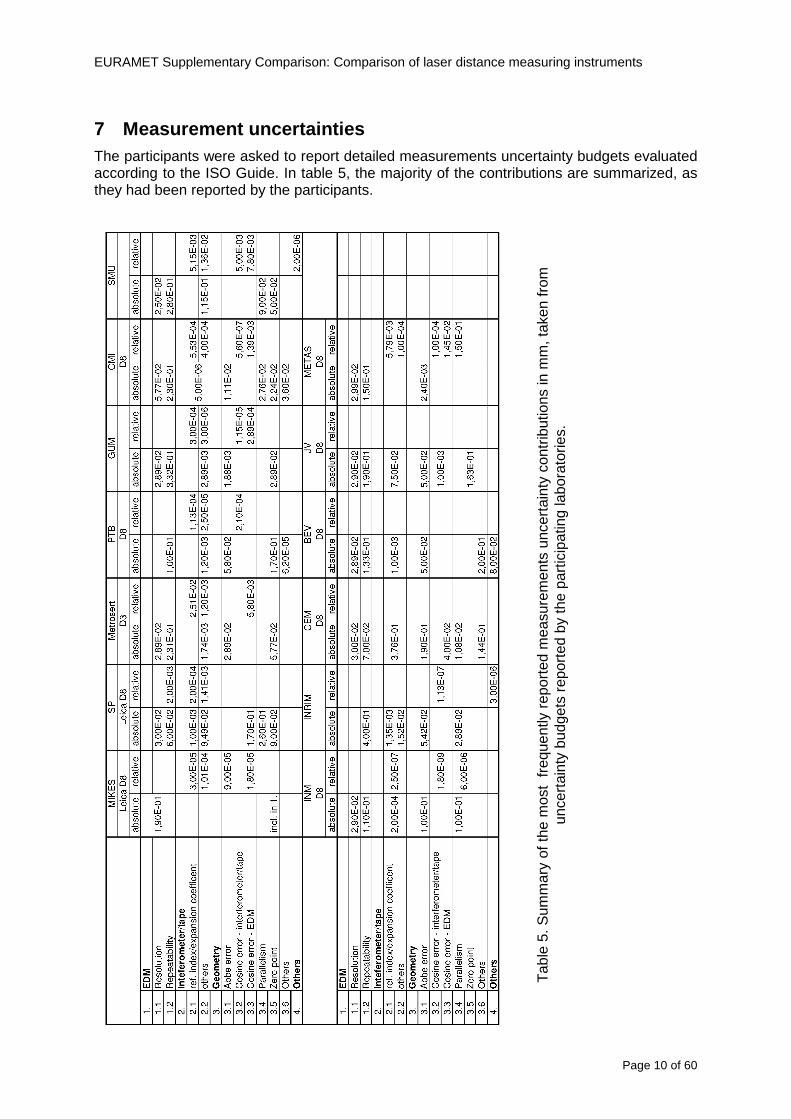
EURAMET Supplementary Comparison Comparison of laser distance measuring instruments
Page 10 of 60
7 Measurement uncertainties The participants were asked to report detailed measurements uncertainty budgets evaluated according to the ISO Guide In table 5 the majority of the contributions are summarized as they had been reported by the participants
Tab
le 5
Sum
mar
y of
the
mos
t fr
eque
ntly
rep
orte
d m
easu
rem
ents
unc
erta
inty
con
trib
utio
ns in
mm
tak
en fr
om
unce
rtai
nty
budg
ets
repo
rted
by
the
part
icip
atin
g la
bora
torie
s
EURAMET Supplementary Comparison Comparison of laser distance measuring instruments
Page 11 of 60
8 Stability of the EDMs
Repeatability measurements showed that in the short period (less than 60 min) indications of the EDMs did not reveal any drift Large differences (~ 15 mm) were also noted between the mean values of the subsequent measurement series performed within 48 hours Considering this effect in uncertainty budget and on the basis of measurements made at the beginning in the middle and at the end of the comparison one cannot determine the drift of the results
Stability measurements Bosch DLE 50
-25
-20
-15
-10
-05
00
05
10
15
20
25
03 5 10 15 20 25 30 35 40 45 50
Length m
Dev
iatio
n fro
m m
ean
m
m
2011 02
2011 08
2012 09
Stability measurements Bosch GLM150
-15
-10
-05
00
05
10
15
03 5 10 15 20 25 30 35 40 45 50
Length m
Dev
iatio
n fr
om m
ean
m
m
2011 02
2011 08
2012 09
Stability measurements Leica DISTO D3a BT
-15
-10
-05
00
05
10
15
03 5 10 15 20 25 30 35 40 45 50
Length m
Dev
iatio
n fro
m m
ean
m
m
2011 02
2011 08
2012 09
Stability measurements Leica DISTO D8
-10
-08
-06
-04
-02
00
02
04
06
08
10
03 5 10 15 20 25 30 35 40 45 50
Length m
Dev
iatio
n fro
m m
ean
mm
2011 02
2011 08
2012 09
Fig 1 Measurements of the pilot laboratory monitoring the stability of all four EDMs at each of the measuring distances bounded by the expanded measurements uncertainty (for k=2 dashed line) The solid curves represent deviation from the arithmetic mean of the three measurements The test of the stability of the EDMs showed significant changes in the mean results in timescale months or even days A detailed analysis of the observed problems will be presented by way of example with Leica DISTO D8 and for a 10 m distance This EDM has been chosen because it is theoretically the best of the compared models with resolution of 01 mm over whole range Depending on the measured distance the EDM is characterized by some measurement uncertainty Typically the standard deviation increases along the distance Distance of 10 m was selected to minimize the impact of the uncertainty on a single measurement The more the distance from the target increases the weaker the reflected signal becomes and the more the uncertainty of a single measurement increases while for very short distances the reflected signal is so strong that it can also have a negative impact on the results
Stability over few minutes time interval
The studies performed showed that deviations from expected value are well characterized by normal distribution Results of those studies are presented in the figure below Probability density of deviations from expected value for Leica D8 for 10 m is consistent with a normal
EURAMET Supplementary Comparison Comparison of laser distance measuring instruments
Page 12 of 60
distribution with standard deviation s = 019 (blue marks ndash experimental red line ndash fitted model)
-10 -9 -8 -7 -6 -5 -4 -3 -2 -1 0 1 2 3 4 5 6 7 8 9 10
dx 01 mm
Fig 2 Distribution of results over few minutes time interval
Stability over tens of minutes time interval
Several series of measurements were made with a duration from 15 minutes to 30 minutes at a constant distance and under constant measurement conditions For most of the series changes in the average value of indications of EDMs have been observed at the level of about 02 mm However for one of the series change exceeds 05 mm (see figure below) This value leads to u = 015 mm
-06
-04
-02
0
02
04
06
08
1
0 5 10 15 20 25 30
t min
dx
mm
Fig 3 Stability of results over tens of minutes time interval
Stability in the timescale of days and months
The measurements were performed in three series of measurements over an interval of a few days The cycle of measurements was repeated twice within a few months The first three measuring series were carried out in February 2011 then in August 2011 and the last one in September 2012
In the figure below the standard deviations of individual measurements of distance are shown with error bars The dashed lines represent minimum and maximum values of individual measurements in the series of measurements
EURAMET Supplementary Comparison Comparison of laser distance measuring instruments
Page 13 of 60
Leica DISTO D8 (interval 010 m)
-06
-04
-02
00
02
04
06
08
10
12
14
series
devi
atio
n fro
m n
omin
al le
ngth
m
m
Fig 4 Results of all series of measurements for Leica DISTO D8 for a distance of 10 m
Having analyzed the graph one can see that the maximum and minimum values in each series performed at an interval of several months do not overlap The mean value in one of the series is not even in a range limited by minimum and maximum for the other series
Such a large differences between the average values appear over a time scale longer than few days This means that the laboratory couldnrsquot observe this variability when briefly examining the instrument
In the figure below probability density of all results from all measurement series was presented
-10 -5 0 5 10 15 20
dx 01 mm
Fig 5 Distribution of all results from all measurement series
Continuous red curve represents the sum of the theoretical normal distributions for each series of measurements Theoretical curve is consistent with the observed distribution
max (x1x9)
min(x1x9)
di
201102 201108 201209
EURAMET Supplementary Comparison Comparison of laser distance measuring instruments
Page 14 of 60
Estimation of uncertainty of artifact
The reproducibility of EDM is affected by random changes of mean values in time scale of days To determine di for a given EDM and a given distance the results from all nine series of measurements )( 91 xx were used
)min()max( 9191 xxxxdi minus=
where i is an index of measurement distance
Set of eleven di was determined for each EDM The figure below presents those results
0
05
1
15
2
25
0 5 10 15 20 25 30 35 40 45 50
Length m
d i
mm
DLE 50
GLM 150
D3s BT
Leica D8
Fig 6 di values for all distances for each EDM
The value of di varies widely This is especially noticeable in Bosh DLE 50 where for the neighboring distances the di values can differ by several times Each EDM is characterized by a different trend
The model assumes that long-term stability is characterized by rectangular distribution with domain described by maximal di and expected value estimated based on all of the measurements Dispersion of individual measurements (short-term stability) is described by normal distribution
The max value of di was used to estimate uncertainty u(dart) related to random changes of EDM results In order to disentangle u(dart) one should try to subtract the observed short term stability from max(di) and influences of the different alignments like zero point uzero cosine error ucos and parallelism uparal [3]
( ) 22cos
2
2
art2
32
)max(paralzero
i uuud
du minusminusminus
=
In the case of Leica DISTO D8 we obtain max(di) = 1133 which corresponds to u(dart) = 0324 mm
Table below contains values of u(dart) estimated for all the four EDMs
EURAMET Supplementary Comparison Comparison of laser distance measuring instruments
Page 15 of 60
Table 6 Values of u(dart) for all the four EDMs
EDM u(dart) (mm)
Bosch DLE 50 0308
Bosch GLM 150 0197
Leica DISTO D3a BT 0149
Leica DISTO D8 0324
Additional stability test of EDMs
The suspected main factors responsible for the change of EDMs indications are 1) Effects of electronics ndash resulting from unstable operation of the EDM 2) Effects of mechanics ndash impact of transport of the EDM between laboratories 3) Effects of geometry ndash alignment repeatability of the EDM during measurements
Two additional experiments were conducted in order to determine which factors have the greatest impact on the results Leica DISTO D3a BT was used for these tests
a) Static test
During the measurements the EDM was immobilized on a bench Measurements were made at a distance of 10 m in a controlled environment The measurement results are presented in the figure below
-04
-03
-02
-01
00
01
02
03
04
1 2 3 4 5 6 7 8 9 10 11 12 13 14 15 16 17 18 19 20
measure
dx
mm
Fig 7 Static stability test results
Each point represents the mean value of 15-20 measurements This test covers about 6 hours of EDM work The standard deviation is s = 009 mm
b) Dynamic test
Measurements were made at a distance of 10 m in a controlled environment After each series of measurements the EDM was removed from the bench shaken and squeezed The aim was to simulate the conditions during transportation This test covers about 6 hours of EDM work Measurement results are presented in the figure below
EURAMET Supplementary Comparison Comparison of laser distance measuring instruments
Page 16 of 60
-04
-03
-02
-01
00
01
02
03
04
1 2 3 4 5 6 7 8 9
measure
dx
mm
Fig 8 Dynamic stability test results
The standard deviation for this test is s = 015 mm and is greater than in the static test
The average standard deviation of three measurement series was estimated using the data from the comparison The value s = 009 mm is similar to the result in the static test
The estimated uncertainty associated with the artifact for this EDM is uart = 015 mm (see table above) The same value u = 015 mm was estimated from the stability test in the scale of tens of minutes Both values are close to the value of standard deviation for the dynamic test
These results may lead to the conclusion that the level of the effects of electronics mechanics and geometry have a similar impact on the long-term stability Due to this fact it is difficult to identify which of these factors has the greatest impact on the observed measurement results
EURAMET Supplementary Comparison Comparison of laser distance measuring instruments
Page 17 of 60
9 Reference values The standard approach is to use weighted mean for determining the reference value xref [12] This is calculated by the mean of all measurement values xi weighted by the inverse square of the standard uncertainties u(xi) associated with the measurements and using these values the largest consistent subset of the sample is determined However checking the consistency of the sample without taking into account the uncertainty associated with the artifact leads to erroneous recognition of the consistent subset We propose to add uart to the uncertainty of each laboratory at the beginning of the calculation
( ) )()( 222iartic xuduxu +=
Thereby the uncertainty associated with the artifact will be taken into account during the consistency check
sum
sum
=
==n
i ic
n
i ic
i
ref
xu
xu
x
x
12
12
)(
1
)(
The pilot laboratory contributed only by its first measurements to the reference values The weighted mean approach requires the individual uncertainties from the laboratories to be estimated according to a common approach (as they should be since all participants were requested to estimate the uncertainties according to the ISO Guide) The standard uncertainty u(xref) of the reference value is calculated by combining the individual uncertainties
sum=
=n
i ic
ref
xu
xu
12
2
)(
1
1)(
The χ2 test was applied in order to estimate xref from the largest consistent subset [1]
EURAMET Supplementary Comparison Comparison of laser distance measuring instruments
Page 18 of 60
Table 7 Reference values and associated standard uncertainties based on weighted mean
Distance Bosch DLE 50 Bosch GLM 150 Leica DISTO D3a BT
Leica DISTO D8
mm xref u(xref) xref u(xref) xref u(xref) xref u(xref)
300 299694 0138 300475 0084 300353 0071 300177 0113
5000 4999900 0139 4999774 0090 5000020 0074 4999659 0111
10000 10000041 0146 9999776 0096 10000285 0077 10000336 0114
15000 14999945 0154 14999781 0120 15000176 0080 15000258 0117
20000 19999804 0175 19999423 0124 20000112 0086 20000581 0118
25000 24999955 0186 24999526 0128 25000321 0094 25000754 0124
30000 29999586 0193 29999956 0138 30000140 0103 30000675 0129
35000 34999779 0235 35000051 0156 35000022 0119 35000844 0153
40000 40000185 0279 40000250 0159 40000476 0132 40001167 0151
45000 44999576 0315 45000208 0165 45000391 0155 45000974 0156
50000 49999983 0324 50000344 0169 50000319 0156 50001137 0157
EURAMET Supplementary Comparison Comparison of laser distance measuring instruments
Page 19 of 60
10 Deviations from reference values The following figures show results from NMIs for all of the distances Reference value is represented by a bold black line
Bosch DLE 50
-30
-25
-20
-15
-10
-05
00
05
10
15
20
25
30
0 5 10 15 20 25 30 35 40 45 50 55
Length m
Dev
iatio
n fr
om n
omin
al le
ngth
m
m
MIKES
SP
Metrosert
PTB
CMI
SMU
INM
INRIM
CEM
BEV
JV
METAS
GUM
Ref
Bosch GLM 150
-20
-15
-10
-05
00
05
10
15
20
0 5 10 15 20 25 30 35 40 45 50 55
Length m
Dev
iatio
n fr
om n
omin
al le
ngth
m
m
MIKES
SP
Metrosert
PTB
CMI
SMU
INM
INRIM
CEM
BEV
JV
METAS
GUM
Ref
Fig 9 Deviations from reference values
EURAMET Supplementary Comparison Comparison of laser distance measuring instruments
Page 20 of 60
Leica DISTO D3a BT
-20
-15
-10
-05
00
05
10
15
20
0 5 10 15 20 25 30 35 40 45 50 55
Length m
Dev
iatio
n fr
om n
omin
al le
ngth
m
m
MIKES
SP
Metrosert
PTB
CMI
SMU
INM
INRIM
CEM
BEV
JV
METAS
GUM
Ref
Leica DISTO D8
-20
-15
-10
-05
00
05
10
15
20
0 5 10 15 20 25 30 35 40 45 50 55
Length m
Dev
iatio
n fr
om n
omin
al le
ngth
m
m
MIKES
SP
Metrosert
PTB
CMI
SMU
INM
INRIM
CEM
BEV
JV
METAS
GUM
Ref
Fig 9 Deviations from reference values (continued)
The deviations Di from reference value xref are calculated by
refxxD ii minus=
For calculating the expanded uncertainty of these deviations U(Di) the corresponding uncertainties u(xi) and u(xref) cannot simply be geometrically added because the values xi and xref are correlated Due to the random changes described in section 6 uncertainty u(dart) was added [2] It can be shown that the expanded uncertainty U(Di) is given by
)()()(961)( art2
ref22 duxuxuDU ii +minus=
when xi belongs to the largest consistent subset and
)()()(961)( art2
ref22 duxuxuDU ii ++=
EURAMET Supplementary Comparison Comparison of laser distance measuring instruments
Page 21 of 60
otherwise The deviations from the reference values are given in various figures and tables below The uncertainty bars in the figures correspond to the expanded uncertainties U(Di) (k = 196)
Fig 10 Deviations from reference values
EURAMET Supplementary Comparison Comparison of laser distance measuring instruments
Page 22 of 60
Fig 10 Deviations from reference values (continued)
EURAMET Supplementary Comparison Comparison of laser distance measuring instruments
Page 23 of 60
Fig 10 Deviations from reference values (continued)
EURAMET Supplementary Comparison Comparison of laser distance measuring instruments
Page 24 of 60
Fig 10 Deviations from reference values (continued)
EURAMET Supplementary Comparison Comparison of laser distance measuring instruments
Page 25 of 60
Fig 10 Deviations from reference values (continued)
EURAMET Supplementary Comparison Comparison of laser distance measuring instruments
Page 26 of 60
Fig 10 Deviations from reference values (continued)
EURAMET Supplementary Comparison Comparison of laser distance measuring instruments
Page 27 of 60
Fig 10 Deviations from reference values (continued)
EURAMET Supplementary Comparison Comparison of laser distance measuring instruments
Page 28 of 60
Fig 10 Deviations from reference values (continued)
EU
RA
ME
T S
upplementary C
omparison C
omparison of laser distance m
easuring instruments
P
age 29 of 60
Table 8 Deviations from the reference value (given at the top of the table) and expanded uncertainties (k=196) of such deviations for BOSCH DLE 50
Table 9 Deviations from the reference value (given at the top of the table) and expanded uncertainties (k=196) of such deviations for BOSCH GLM 150
EU
RA
ME
T S
upplementary C
omparison C
omparison of laser distance m
easuring instruments
P
age 30 of 60
Table 10 Deviations from the reference value (given at the top of the table) and expanded uncertainties (k=196) of such deviations for Leica DISTO D3a BT
Table 11 Deviations from the reference value (given at the top of the table) and expanded uncertainties (k=196) of such deviations for Leica DISTO D8
EURAMET Supplementary Comparison Comparison of laser distance measuring instruments
Page 31 of 60
11 En Tables Results with En gt 1 are marked with red color in Tables below En values are calculated by Di U(Di) with Di and U(Di) as given on page 19
Table 12 BOSCH DLE50
Lab Distance (mm) 300 5000 10000 15000 20000 25000 30000 35000 40000 45000 50000
MIKES -058 017 -019 -023 035 -002 -096 SP 020 019 006 005 009 059 064 037 028 097 001
Metrosert -030 -031 -003 018 032 PTB 001 029 022 -006 011 -036 001 -023 -075 -083 001 GUM -033 -005 -018 -009 000 006 017 005 -026 -028 019 CMI -003 020 -009 004 005 -022 028 SMU 006 -049 -034 -023 -017 -057 051 039 021 INM 032 031 037 006 020 005 -079 -119 -272 -260 -269
INRIM 025 -013 000 096 CEM -032 -022 -041 -039 -004 -038 080 001 -094 -047 BEV -010 007 000 -001 008 -011 037 013 -001 008 -001 JV -019 -016 025 -055 055 060 068 163 122 060 089
METAS 038 012 -005 007 -107 004 -024 002 -070 037 -052
Table 13 BOSCH GLM150
Lab Distance (mm) 300 5000 10000 15000 20000 25000 30000 35000 40000 45000 50000
MIKES 005 -002 019 018 027 019 062 SP 003 068 029 023 051 008 015 016 -005 -001 038
Metrosert -061 -011 -022 -021 -003 PTB 066 074 062 062 034 053 047 048 047 091 064 GUM -007 -014 007 -018 000 023 020 033 014 032 038 CMI -057 -032 -030 -064 -050 -047 000 SMU 023 -024 -060 012 062 001 -003 050 047 INM -022 017 -003 002 -003 054 005 -006 016 -022 -055
INRIM 079 -052 -050 -026 -034 -042 CEM 002 002 -034 -020 -029 -077 -077 -077 -074 -104 BEV -004 -002 -007 010 -042 -042 -029 -011 -028 -022 -030 JV 003 015 040 011 -020 021 -029 -005 028 036 058
METAS -047 -020 005 002 -012 -033 -054 -065 -053 -082 -040
Table 14 Leica DISTO D3a BT
Lab Distance (mm) 300 5000 10000 15000 20000 25000 30000 35000 40000 45000 50000
MIKES 008 094 050 -011 028 051 045 SP 033 038 056 017 053 065 076 051 017 071 011
Metrosert -060 -004 -037 -014 -002 PTB 067 000 070 030 089 062 061 081 124 050 072 GUM 023 019 035 008 038 053 029 058 070 064 063 CMI -001 -004 027 -011 011 034 -033 SMU 002 -013 -019 007 -013 -055 045 -013 -042 INM 002 -039 -058 001 002 -045 -080 -051 -102 -101 -378
INRIM 070 -020 063 101 CEM -028 -004 -004 -064 003 -002 -050 -022 -093 -160 BEV -032 -019 -019 004 -011 -037 -017 -002 -025 005 012 JV 027 019 027 042 046 039 043 048 072 115 024
METAS -091 -008 -102 -098 -111 -103 -092 -080 -073 -108 -043
EURAMET Supplementary Comparison Comparison of laser distance measuring instruments
Page 32 of 60
Table 15 Leica DISTO D8
Lab Distance (mm) 300 5000 10000 15000 20000 25000 30000 35000 40000 45000 50000
MIKES 025 013 058 036 038 061 022 SP 057 026 040 016 013 016 025 017 -007 -019 007
Metrosert -021 006 -016 -043 -019 PTB 040 011 035 -005 -011 -002 -004 035 047 022 069 GUM -028 005 -025 031 039 -015 029 048 041 052 072 CMI -104 -026 -072 -057 -006 -017 -015 SMU -067 -017 -051 -026 -016 -054 -004 -001 -016 INM 021 -014 009 003 -017 -031 -010 007 029 036 041
INRIM 076 -024 -004 047 -007 083 CEM 004 -009 002 -033 -051 -059 -097 -077 -116 -134 BEV -057 -014 -051 -093 -024 -027 -021 -036 -038 -028 -041 JV 014 031 047 030 044 043 035 056 093 108 030
METAS 035 007 026 038 -013 -024 -011 -048 -089 -074 -066
12 Conclusions It was the first comparison of EDMs For most of the laboratories it was an important opportunity to validate their measurement instrumentation and procedure It allowed to become aware of potential problems and to take corrective actions in changing the procedure
For the evaluation of the reference value the weighted mean approach has been chosen although the consistency check according to procedure A of Ref [1] failed in many cases A more complicated procedure for the evaluation of the reference value was proposed which slightly changes the uncertainty of the reference value
In total there were 23 En values larger than 1 This represents 47 of the full set of 482 results It is less than the 5 of possible values being out of the expanded uncertainty of the reference value for k=2
The uncertainty of the results mainly comes from the uncertainty of the reproducibility It is difficult to distinguish between Labrsquos calibration and measurement capability
The comparison shows a global compliance with declared CMCs independently of whether some participant can have a high percentage of values not compliant with its CMC due to the influence of the artifact and the estimation of its uncertainty
13 References [1] M G Cox The evaluation of key comparison data Metrologia 39 589 ndash 595 (2002)
[2] R Thalmann EUROMET 677 ndash Steel Tape Measures Final report (2004)
[3] F Pollinger personal communication
EURAMET Supplementary Comparison Comparison of laser distance measuring instruments
Page 33 of 60
Appendix 1 Description of the measurement equipmen t as reported by the laboratories
A11 MIKES Finland
Short description of measurement bench
MIKES interferometric bench is situated in an underground laboratory with air temperature and humidity control Typically air temperature is 20 plusmn 01 degC and humidity 45 plusmn 2 RH The linear guide on the top of the concrete beam comprises two parallel round shafts with adjustable fixtures every 1 m A carriage with ball bush bearings is moved along the rail and location of it is measured with reference interferometer HP-5529A Temperature of air is measured with 6 pt100 sensors and Keithley 2010 multimetre with 4-wire resistance mode Air pressure and humidity are measured with Vaisala PTU200 Updated Edleacuten equation by Boumlnsch amp Potulski is used for calculation of refractive index of air
For EDM calibration on the other end than laser interferometer is a fixed reference plate which is adjusted perpendicular to the laser beam Next to the reference plate is an adjustable base for EDM instrument with which it can be adjusted to point parallel and coincident with measurement arm of the interferometer A target plate adjusted perpendicular to laser beam is fixed to the carriage The calibration followed Abbe principle with some millimetre uncertainty in offset adjustment
First reference interferometer is set to zero when the target plate and reference plate are in contact then EDM is positioned and adjusted in its base The rear surface of the EDM is also slightly pressed against reference surface behind it Then the readings from both instruments are collected at selected locations For this calibration there is no fine adjustment of the target position so there are typically deviations of up to few millimetres from nominal locations Results are averages of 3-4 measurements
Additional remarks
The CMC entry MIKES has for EDM calibrations is based on calibration of length scales of high quality total stations and laser trackers This type of EDMs used in this comparison are not accurate enough for truly testing of MIKES calibration measurement capability
EURAMET Supplementary Comparison Comparison of laser distance measuring instruments
Page 34 of 60
A12 SP Sweden
Short description of measurement bench
The bench consists of a simple aluminium Uminusshaped profile with polished steel pins acting as supports for the tape The bench is a little over 50 m long and works as support for the reference tape and the calibrated EDMs simultaneously
Length measurement instrument
Comparison with reference steel tape
Temperature measurement system number and location of sensors
The tape temperature is continuously registered in 6 points equally distributed along the bench The air temperature is monitored during the measurements but not used for corrections
Additional remarks
The EDM support is placed approximately 2 cm vertically above the tape No visual aid is used
EURAMET Supplementary Comparison Comparison of laser distance measuring instruments
Page 35 of 60
A13 AS Metrosert Estonia
Short description of measurement bench
The 21-m bench is located in the designated corridor-like laboratory room The lab is air-conditioned and the stability of temperature is typically plusmn05 ordmC There are three humidity and temperature sensors in room for stability and gradient monitoring
Two stainless steel rails running in parallel are made of 3-m long rods The rails lay without fixed attachment on metal supports which are mounted on concrete base The base rests on pillars made of bricks
Length measurement instrument
Laser-interferometer system Renishaw ML10 was used as length measurement instrument
Laser interferometer gets temperature humidity and pressure data from itrsquos own measurement system EC10
Additional remarks
Due to the length of the bench only measurements up to 20 m could be made Five measurement series were made with each EDM
EURAMET Supplementary Comparison Comparison of laser distance measuring instruments
Page 36 of 60
A14 PTB Germany
Short description of measurement bench
The measurements were performed on the 50 m geodetic base of the PTB The comparator consists of a 50 m rail The laboratory is equipped with a network of 21 temperature sensors spaced by 25 m along the bench As depicted in fig 1 the EDM is mounted at one end of the comparator the reflector is fixed vertically on the carriage A large retroreflector is mounted approximately 150 mm below the EDM reflector on the carriage reflecting the beam of the reference interferometer The deviation of the length due to tilting carriage (Abbe error) has been investigated along the bench by comparison of two interferometers It remains smaller than 100 microm The distance of the first position of 300 mm with respect to the back side of the EDM is determined by a gauge block of 300 mm length and a thickness of 10 mm This procedure is depicted for one of the comparison standards in figure 2
For the calibration the desired positions are programmed After the carriage reaches a measurement position the operator waits for another 30 s for the carriage to settle In control experiments the remaining movement between positioning and measurement remained smaller than 2 microm The operator then activates the measurement of the EDM reads the indicated position and writes it down The procedure is repeated for twelve times at every position the mean of the 12 measurements represents the ldquoindicated distance by the EDMrdquo All measurements of a single run at one position are performed within approximately one minute The complete measurement was repeated for four times
Length measurement instrument
The reference length is determined by a frequency-calibrated laser interferometer (Agilent 5519A) The reference interferometer is set up in Michelson geometry the signals being digitalised by a Heidenhain IK 121 card The index of refraction is determined by the external weather station of the geodetic base consisting of 21 Pt-100 temperature sensors spaced 25 m along the bench two humidity sensors (Testo 650) and two pressure sensors (Setra 370 and DPI 141) The environmental parameters are used to determine the index of refraction for the reference measurement deploying the modification of the Edleacuten equation by Boumlnsch and Potulski
EURAMET Supplementary Comparison Comparison of laser distance measuring instruments
Page 37 of 60
A15 CMI Czech Republic
Description of measurement bench
The EDMs were measured on 30 m long measuring bench equipped by laser interferometer (LI) Renishaw ML10 (pic 1 and 2) calibrated traceable to national standard of length and quantities of environmental sensors The target plate and retroreflector of the LI were fixed on a moving part of the bench and each EDM was fixed in horizontal position by clamps (pic 3) LI and EDM are placed on opposite ends of bench the Abbe offset was lt10 mm for some of them and lt50mm for all The value of LI was reset (to zero) at position corresponding to the rear of the EDM (using 3D measuring arm FARO Quantum with uncertainty about 27microm) The perpendicularities of the EDM stop as well as target plate to the beam were also checked by FARO) Each EDM was 3x replaced and aligned the measurement (reading) was repeated 6 times for each alignment and position the mean value of these 3x6 measurements is stated in tables with results The uncertainty claimed covers the statistical uncertainty of single readings Only in case of Leica D8 (the best performing EDM in this comparison) we state also the uncertainty corresponding to the mean of 6 readings in last column (this uncertainty is smaller and better illustrates our CMC)
Length measurement instrument
- Laser interferometer Renishaw - Laser 633 nm Type ML10 - Compensator EC10 - 3D measuring arm FARO Quantum - 3D measuring arm FARO Quantum
EURAMET Supplementary Comparison Comparison of laser distance measuring instruments
Page 38 of 60
A16 SMU Slovakia
Short description of measurement bench
No bench is available at the SMU the measurements are being carried out in the underground corridor of the laboratory building with length of 428 m
The 50 m steel measuring tape KINEX was used as the reference laid on the floor and pulled by the force 50 N (the same force as had been applied during its calibration at the SMU) The calibration of reference tape was done at the SMU using ULM3m Zeiss with laser interferometer Agilent 5529 B (ie per 3 m parts)
Three mercury thermometers with the resolution of 01 degC were used along the measurement path each of them laid onto the tape and located at 667 m 1990 m (instead of 20 m because of this was one of measuring points) and 333 m respectively Each of them thus corresponded approximately to one third of the measured steel tape section
Regarding the 03 m measuring point the ULM3m Zeiss length measuring machine was used with the 300 mm gauge block as the reference
Length measurement instrument
We used our own target plate being fixed perpendicularly (within uncertainty stated) to the construction equipped with nonius and the camera holder transported manually along the steel tape The second construction was fixed to the tape by such a way that zero line of the tape corresponded to the rear of EDM (within uncertainty stated)
The position of the target is read on the monitor and 20 repeated readings of the EDM data took place in each measuring point (multiples of 5 m up to 40 m)
Concerning 03 m the 300 mm gauge block was fit between the target plate and the construction with EDM The distance of the EDM rear from the target plate corresponded to the length of gauge block (within uncertainty stated)
Additional remarks
The identical measurement method was used as we use to do within our calibration service although the results reporting is different ndash we provide the regression line calculated from the measurement of irregularly distributed points and corresponding uncertainty (k = 2) in the form of [a bL] mm (ie the same coefficients for each length in the range (0 ndash 42) m)
SMU hasnrsquot got this category in CMC tables
EURAMET Supplementary Comparison Comparison of laser distance measuring instruments
Page 39 of 60
A17 INM Romania
Short description of measurement bench
Geodesic base located in the basement of the laboratory with nominal length equal to 50 m having a mobile carriage thet support both laser He-Ne retroreflector and the target of the laser distance measuring instrument in the front of geodesic base exists a support where are aligned both laser interferometer and the laser distance measuring instruments
Length measurement instrument
Laser interferometer type Hewlett Packard model 5526 A with nominal length equal to 50 m resolution 0001 mm
U = 02 microm +0510-6L
Additional remarks
During the measurements the maximum gradient of temperature was equal to 05 degC
EURAMET Supplementary Comparison Comparison of laser distance measuring instruments
Page 40 of 60
A18 INRIM Italy
Short description of measurement bench
The facility for long distance measurements is located in a corridor of the gallery devoted to dimensional metrology The structure consists in a 28 m long rail fixed to a series of pillars which rest directly on the ground released from the vibrations of floor and wall The measuring system is based on a heterodyne interferometer whose mobile arm consists of a hollow retro-reflector mounted on a structure that can run along the rail so-called carriage A photograph of the facility is presented in Fig1
The carriage is moved by a micro-step motor the motor driver receives a digital pulse and converts it into an electrical pulse to run the motor Each pulse causes a rotation of the motor shaft of one step which amounts to 11000 of a complete revolution of the shaft If the pulse frequency increases the rotation becomes continuous with a speed that is directly proportional to the pulse frequency The speed ranges between few microms up to 27 ms with a resolution of 03 microms
Since the carriage must move back and forth automatically for a distance of almost 30 m a remote control to send pulses to the motor driver was implemented It consists of two parts a radio command which allows to set some general parameters of the carriage movement such as the movement direction and mode of travel (slow or fast) and a fast command which is performed by an amplitude modulated laser beam placed at the beginning of the track oriented towards the carriage A photo detector placed above the carriage receives the modulated laser beam which is transformed into pulses to be sent to the driver of the motor The modulation of the laser beam is implemented by a LabView program that controls a digital output of the data acquisition device
Length measurement instrument
The length measurement instrument is based on a heterodyne incremental interferometer The main beam of the interferometer with frequency f1 is generated by a frequency stabilized
EURAMET Supplementary Comparison Comparison of laser distance measuring instruments
Page 41 of 60
He-Ne laser calibrated with respect to the INRIM length standard and sent to the measurement arm the second beam is a portion of the first one diffracted by an acousto-optic modulator (AOM) with frequency f2 = f1 + 80 MHz The reference detector acquires the beat note signal at 80 MHz while the measurement detector acquires a signal at 80 MHz whose phase is varied due to the displacement of the retro-reflector moving on the rail In figure 2 the optical design of the interferometer is presented
Two different measuring techniques have been implemented
1 the ldquophase measuringrdquo technique based on fringes counting with a relative uncertainty of 5middot10-7 but limited at the maximum carriage speed of 3 cms
2 the ldquoDoppler frequency measurementrdquo technique for higher carriage speed based on the measurement of the Doppler frequency shift while the carriage runs
The second technique was validated by means of the comparison with the first technique at low speed with an agreement of the order of 3middot10-6 hence the Doppler frequency method could be considered validated within 01 mm over the whole rail path with the advantage of reducing the time needed to cover long distances so it was used for the EDM comparison
In order to obtain the distance covered by the carriage according to technique 2 the Doppler frequency is measured by a commercial high-performance counter (a Pendulum CNT-90) without dead time based on time stamping then it is converted in speed and integrated over time according to the following formula
( ) ( )int minus=minus= tffn
dtn
ffdairair
λλ
2
1
2
1
where d is the distance covered by the carriage f is the frequency of the measuring signal with the carriage at rest frsquo the frequency of the measuring signal with the carriage moving λi
is the wavelength of the laser in vacuum n - air is the air refractive index and ti is the integration time The difference frsquo-f is just the Doppler frequency due to the moving carriage
The time interval measurement resolution of the instrument is 100 ps and the time base is
EURAMET Supplementary Comparison Comparison of laser distance measuring instruments
Page 42 of 60
connected to the INRIM UTC so that the measurements of the Doppler frequency and the integration time are extremely accurate The environmental parameters such as air temperature atmospheric pressure partial pressure of water were monitored during the measurement process in order to calculate the value of air refractive index according to the Edlenrsquos formula
Comparison set-up
The different technical solutions adopted for the EDMs and for the target plate positioning are discussed in this paragraph and sketched in figure 3
Fig 3 picture of the EDM and target positioning area
Target plate positioning
In order to use the provided target plate an ad-hoc mounting was manufactured at INRIM it consists in a sort of picture frame made in aluminum which slightly clamps the target folded in half and gives it the necessary stiffness to be a reproducible target The upper part of the frame is L-shaped and allows it to be fixed to the carriage structure by means of two screws The rear part of the target mounting is depicted in figure 4 The target mounting was considered necessary because of the poor stiffness and planarity of the plastic target With the aluminium frame a planarity better than 01 mm was guaranteed The target plate is placed few centimetres next to the retro-reflector and normal to the interferometer beam axis since the EDM laser should be as close and parallel as possible to the reference beam
EURAMET Supplementary Comparison Comparison of laser distance measuring instruments
Page 43 of 60
Fig 4 picture of the rear part of the target plate mounting
EDMsrsquo positioning
The EDMs are placed on a cradle-like platform which is able to adjust the inclination of the EDM along the longitudinal axis (pitch angle) The platform height allows the EDMs to be at approx the same height as the interferometer beam A crucial role was played by the stop-wall placed behind the platform since it represents the ldquozero pointrdquo for all the length measurement Hence a particular effort was devoted to align the stop-wall so that it was normal to the interferometer beam axis and parallel to the target plate
Fig 5 detail of EDMsrsquo positioning the cradle-like platform and the stop-wall are well visible
EURAMET Supplementary Comparison Comparison of laser distance measuring instruments
Page 44 of 60
Target and stop-wall alignment
In order to have the stop-wall parallel to the target plate and normal to the interferometer beam axis the following procedure has been used
1) the stop-wall and the target plate were roughly placed trying to set them parallel and normal to the rail by eye (ie within few millimeters)
2) in order to check if the target was normal to the rail one EDM was positioned on the platform the pitch and yaw angles of the EDM were adjusted by observing the position of the EDM laser spot on the target plate when the target is moved along the rail fixed position means laser beam parallel to the carriage movement Then the target was moved until the end of the rail and a thin mirror was kept in contact with it hence observing the EDM laser reflected by the mirror it was possible to adjust the target tilt acting on the screws until the laser beam is reflected back to the source
3) finally in order to check the parallelism between the stop-wall and the target a tool made by a laser pointing orthogonally to its base was used the base was leant against the stop-wall and the laser was centered on the target when the target is near then the target was moved until the end of the rail hence observing the spot of the laser on the target it was possible to adjust the stop-wall orientation
The residual misalignment errors which we were not able to eliminate were kept into account in the uncertainty budget
Measurement of the first 30 cm
Due to the geometry of our set-up it was not possible to perform the first point of measurement by means of the interferometer indeed the carriage (hence the target) is not able to go in contact with the stop-wall
Fig 6 measurement of the first 30 cm the ruler touching the stop-wall and the target and the mechanical probe (in the back) touching the carriage are visible
EURAMET Supplementary Comparison Comparison of laser distance measuring instruments
Page 45 of 60
So a ruler made of aluminum with rounded ends and nominal length equal to 30 cm was adopted to set the distance between the target plate and the stop-wall for the first point of measurement as it is shown in figure 6 The ruler whose length was measured by a CMM machine was inserted between the target and the stop-wall leaning against the latter and the carriage was carefully moved towards the stop-wall until the target lightly touched the ruler A mechanical probe that touches the carriage structure when carriage is in the ldquo30 cmrdquo position was used as a reference measurement to check the repeatability of this distance after each measurement set
Fig 7 detail of the mechanical probe touching the carriage
Environmental parameters
The environmental parameters such as air temperature atmospheric pressure and humidity were monitored during the whole measurement process in order to calculate the value of air refractive index according to the Edlenrsquos formula
Among these parameters the temperature distribution along the mobile arm of the interferometer was our main concern mainly for two reasons
1 the temperature control of the gallery was not perfectly working during the measurement period so temperature drifts had to be monitored
2 longitudinal temperature gradients due to non uniform heating and to the presence of electronic instruments were pretty high
To the purpose 14 thermometers were uniformly dislocated along the rail and automatically recorded for all the measurement period Both temporal drifts and gradients along the path have been taken in account in the uncertainty budget In any case maximum temperature differences along the rail are within 1 degC In fig 8 an extract from the acquisition file is shown
Unfortunately the air conditioning system did not work well during the measurement campaign hence the measurements were performed at a mean temperature of 209 degC
EURAMET Supplementary Comparison Comparison of laser distance measuring instruments
Page 46 of 60
Fig 8 each curve represents the temperature distribution along the rail during the measurements campaign
Carriage waving
Since the rail is not perfectly straight and the measurement laser is not coincident with the measurement beam the Abbegrave error due to waving of the target must be considered A quantitative measurement and a qualitative measurement were carried out With an electronic level placed on the carriage the straightness on the vertical plane has been mapped with a half meter resolution (the data are reported in fig 9) With a laser placed on the carriage the horizontal and vertical waving are qualitatively compared by looking at the movements of the light spot on a target fixed to the rail end As a conclusion the horizontal and vertical waving are comparable in magnitude and the peak to peak error is of the order of 300 arcseconds
Fig 9 vertical waving of the target measured by an electronic level placed on the carriage
EURAMET Supplementary Comparison Comparison of laser distance measuring instruments
Page 47 of 60
Measurement procedure
The measurements were carried out according to the following procedure
The target was set in the starting position with the procedure described above
In sequence the four EDMs are positioned on the base the horizontal and vertical tilt are adjusted and the distance measurement is recorded An additional fifth EDM (Bosh DLE 150 property of INRiM) was included in the measurement sequence Each EDM is placed on the base and gently pushed against the reference wall in such a way that the measurement laser beam starting point is the same for all EDMs Than the horizontal and vertical angles were adjusted in order to hit the central point of the target indicated with two black marks (see pictures 3 and 6) with ldquovisualrdquo alignment The measurement button is then pressed several times (typically 5) and the average reading is recorded Typical dispersion between readings is within few last digit units In case the dispersion between readings is too large the anomaly is recorded
The carriage was then moved in the next position (about 5 m) and the measurement sequence was repeated for the 5 EDMs The operation is repeated up to 25 m The 25 m measurement is than repeated again as well as all the points till the first one so that each point is measured twice each set Since the carriage movement is ldquoopen looprdquo the positioning of the carriage was not exactly in the nominal 5 m intervals For each positioning the incremental displacement is measured by the interferometer in the Doppler mode Finally the measured values were averaged in order to give a single value for each nominal position
At the end of the measurement set when the carriage is at the 30 cm position again the sum of the interferometric measurements should be very close to zero The residual value is compared with the difference between the first and the final measurements of the mechanical probe The difference must be within the uncertainty of the Doppler technique otherwise some error occurred in the measurement set that must be repeated
At the end of the session 10 complete sets of measurements recorded from the 20th to the 30th of January 2012 have been considered for this report
Additional remarks
Effect of laser pointing
During a preliminary set of measurements we noticed a strong and unexpected dependence of the measurement result on the position of the laser spot on the target Indeed since no particular instructions were given about the relative position of the laser spot on target position (except to exclude the central joint between the two halves) we decided to work relatively close to the right side of the target -closer to the interferometer beam- in order to reduce the Abbegrave error We noticed very large errors at large distances in particular of the Leica DISTO D3a (see figure 10)
EURAMET Supplementary Comparison Comparison of laser distance measuring instruments
Page 48 of 60
Fig 10 errors of each EDM In a preliminary set of measurements
We also noticed that this error was strongly dependent on the position of the spot on the target For this reason we carried out a set of measurements at the maximum length in different positions of the target from one edge to the other according to figure 11 The results are reported in table V
EDM A B C D E
Leica D3a -4 +1 0 +24 +43
+2 0 +42 +40
-1 0 +38
Leica D8 0 0 0 2 +7
0 +12 +23
table V deviations (in mm) from the length measured at point C aiming the laser spot at different positions of the target (notations as in figure 11)
We tried to find an explanation to this effect in the shape of the laser spot if the spot was
EURAMET Supplementary Comparison Comparison of laser distance measuring instruments
Page 49 of 60
particularly defocused or had high diffraction some of the energy could fall out of the target and affect the measurement result In fact the images of the spots (shown in fig 12) do not support this hypothesis Finally we decided to use the center of the (half) target for the comparison
Changing the target
In order to investigate the influence of the target on the measurements a cardboard foil (400 x 400) mm was fixed to the target mounting and a complete set of measurements was performed The results reported in figure 13 and 14 do not show any evidence of a possible dependency of the EDM measurement on the target kind
EURAMET Supplementary Comparison Comparison of laser distance measuring instruments
Page 50 of 60
Measurement at 50 m
Although we are not able to perform traceable length measurements beyond 28 m we wanted to get a sense of EDMs behaviour at longer distances So a target (represented by a rack side wall) was placed at approximately 50 m one after the other the EDMrsquos were positioned on the base and pointed towards the target The measurements were repeated then the target was replaced by the target used for the comparison and a third set of measurements were performed To our great surprise all the EDMrsquos were in good agreement (within 2 or 3 mm for each set of measurement) even those which showed errors of the order of five to ten millimeters at 25 m namely BOSCH DLE 50 and LEICA DISTO D3a Therefore each set of measurements was averaged and the deviations from the mean value are reported in figure 15
EURAMET Supplementary Comparison Comparison of laser distance measuring instruments
Page 51 of 60
Fig 15 Deviations from average value of the measurements At 50 m
EURAMET Supplementary Comparison Comparison of laser distance measuring instruments
Page 52 of 60
A19 CEM Spain
Short description of the measurement bench
To make the measurements of EDMs we have used a reference line made of adjustable supports fixed on a wall of the laboratory Each support is nominally separated five metres from the previous one so we can generate reference lengths up to fifty metres with a pitch of five metres The supports are designed to accommodate both targets and handheld EDMs Distances between supports were measured by using a total station traced to national standards The relative angles of the bases have been measured and corrected
Fig 1 - View of three consecutive supports of the 50 m baseline (left) Lab technician situating an EDM on the first support of the baseline (right)
Length measurement instrument
The baseline was calibrated by using a total station Leica TDA5005 with spherical reflector the calibration uncertainty being 02 mm for k = 2
The target is provided by the comparison The quality of the target was judged as not good due to geometrical constructive errors and the lack of rigidity and stability We measured the flatness of the target surface the distance edge-surface and the angle between them by using a 3D coordinate measuring machine The results of flatness and angle were included in the uncertainty budget and the distance EDM-target was corrected for each EDM due to each beam impinged on a different point of the target
We were not able to measure the distance 0 to 03 m because the baseline pitch is 5 meters and although we are able to measure shorter values in a different facility the target was not appropriate for our bench
EURAMET Supplementary Comparison Comparison of laser distance measuring instruments
Page 53 of 60
Fig 2 - View of an EDM on the first support of the baseline (left) A closer look showing the support adjustments and the origin plate (right)
Fig 3 - View of the comparison target on one of the supports of the baseline (left) A closer look showing the target edge against the support rigid reference (right)
Measurement method
The measurements were carried out by comparison against the known values of the calibrated baseline (metallic references on supports)
Environmental conditions were maintained within the following limits
- Temperature 20 ordmC plusmn 05 ordmC
- Humidity 45 plusmn 10
Each laser distance measuring instrument was placed at the first support of the base and aligned so that the laser beam was perpendicular to the target as indicated by the comparison protocol
For each measurement we took the average of thirty measurements It permitted us to evaluate the repeatability of the instrument
EURAMET Supplementary Comparison Comparison of laser distance measuring instruments
Page 54 of 60
A110 BEV Austria
Short description of the measurement bench
Fig 1 Carriage of tape bench View from the laser interferometer side Retroreflector mounted on the vertical plate the EDM target is mounted on the backside
Fig 2 Support for the DUT Adjustable with 2 translational and 2 rotational degrees of freedom respectively
Fig 3 Setting of the 300 mm starting position Note the rough-and-ready mounted target plate
Fig 4 Laser interferometer side of the bench The DUT is 50 m away on the other side
EURAMET Supplementary Comparison Comparison of laser distance measuring instruments
Page 55 of 60
Measurement procedure 1 The EDM is positioned with the help of a 4-axis positioning stage so that its laser beam is
coaxial with the measurement direction of the laser interferometer (in head on configuration)
2 The EDM is removed from its support The bench carriage is positioned so that the distance of the target plate from the EDM back support is 300 mm A length bar with spherical faces is used for this adjustment The laser interferometer is preset to 300 mm and the EDM is put back on its support
3 At each position 10 consecutive measurements are taken (repeatability) and the carriage is moved to the next position The carriage is manually moved under control of the laser interferometer until it is within plusmn30 microm at the correct position (Exception for the DLE 150 the target is not positioned at 10 m but at 10 m ndash 1 mm to make use of the higher resolution) The indicated (not the nominal) distance of the laser interferometer is recorded for the determination of the deviation
4 After reaching the 50 m position all points are measured in reverse order (bidirectional) Immediately after the last measurement the EDM is removed and the indication using the 300 mm length bar is checked (thus noting a possible drift of the setup)
5 Each instrument was measured 4 times according to this procedure on different days (reproducibility of bench and instrument)
Length measurement instrument
Agilent laser interferometer with long range option The bench was completed short time before performing these measurement So the characterisation was not complete and the respective measurement uncertainty of the laser interferometer is estimated rather high But anyway its contribution to the overall uncertainty can nearly be neglected
Additional remarks
The uncertainty originating from the DUT is the dominating uncertainty contribution Specifically the resolution of the two Bosch instruments (1 mm) and the repeatability are the largest contributions For the DLA 50 the pooled standard deviation of a reading at 50 m is larger than 2 mm Moreover the length dependence is not a simple function
All of the instruments show a significant deviation of the laser beam from the normal of the back (reference) face of the instrument The measured angles reach from 04deg (D3a) to 11deg (DLE 50) This leads depending on the outer dimensions of the instruments to a constant uncertainty contribution of 02 mm in our setup It must be noted that the reference faces are not well defined in most of the instruments
The reproducibility is quite different for the four instruments so only part of it originates from the setup For CMC claims we will use the standard uncertainty value of the most reproducible instrument (D3a) which amounts to 013 mm For an ideal instrument with a resolution of 01 mm and perfect repeatability we would thus have a constant expanded uncertainty of 053 mm up to 50 m
EURAMET Supplementary Comparison Comparison of laser distance measuring instruments
Page 56 of 60
A111 JV Norway
Short description of measurement bench
EDM under calibration and the reference system are aligned along a 50 m measurement bench with rails to carry the linear movement of a target plate for the EDM and a corner cube reflector for the reference system The distance between parallel axis of EDM and axis of the reference system is 130 mm Abbe error due to angle errors for the movement is smaller than 01 mm and is corrected for at each measurement point At long lengths an aperture is used approximately midway between the target plate and the EDM to avoid interfering stray light to the EDM
Alignment procedure
1) Alignment of reference system to the movement of the carriage (rails)
2) Alignment of the EDM to the movement of the carriage (rails)
3) Alignment of a plane mirror at the position of the target plate using back-reflection to the EDM output (normal incident of light on the mirror)
4) Take out the EDM and align the zero reference plate at the back of the EDM to the plane mirror
5) The mirror is replaced by the target plate and the target plate is aligned to the zero reference plate
6) Zero setting of the reference measurement system when target plate is at zero distance to the reference plate at the back of the EDM
7) Put the EDM back in position and realign it to the movement of the carriage (rails)
8) Zero setting of the EDM to the reference plate
Image 1) Image 2) Image 3) Image 4)
Image 1) Items 5) ndash 6) in alignment procedure
Fixture for HP linear interferometer is seen bottom right Part of Wyler instrument is seen to the left blue colour
Image 2) Items 7) and 8) in alignment procedure
Micrometer screws for angle alignment in two directions and linear translation for zero setting of the EDM Push button on the EDM is positioned at the tilting point of the angle adjustment table to maximize stability during measurement HP 5519 A laser head is seen to the right
Image 3) Ready to measure at selected distances from zero point the reference plate
Image 4) EDM spot size at 50 m
Length measurement instrument
- Hewlett Packard Dynamic Calibrator 5519 A (max range 80 m)
- Pressure air temperature humidity Vaisala
EURAMET Supplementary Comparison Comparison of laser distance measuring instruments
Page 57 of 60
- Digital high resolution angle measurement Wyler
I used our own target plate which is of the same type as enclosed in the artefact suitcase article number 766560 from Leica but with reduced size width x hight = 90 x 137 mm
The zero reference plate is of similar type and size
Before measurements batteries of EDMs were switched to new batteries Old batteries are switched back after calibration
For L gt 5 m an aperture of similar size as the target plate is used approximately midway between the EDM and the target plate
Additional remarks
Reports on EDM indicated values at each measurement point is the average value of n = 5 repetitions A linear model of the standard deviation for the repeatability of the EDM readings at different lengths is estimated using m = 20 repetitions at least 5 positions along the scale An estimate of the length dependent repeatability is made for each instrument
The expanded uncertainty U(95) is rounded up to the limiting resolution of 1 mm in the interval 10 m to 40 m for Bosch GLM 150
After the calibration we also estimated the angle error of the optical axis of the EDM to its back plane (back reference of EDM) Bosch DLE 50 26 mrad up measured at 50 m Bosch GLM 150 8 mrad to the left measured at 50 m Leica DISTO D3a 37 mrad down measured at 20 m Leica DISTO D8 2 mrad to the left and 4 mrad down (45 mrad total) measured at 20 m
The distance between parallel walls will be measured too large if the back plane is assumed to be normal to the optical axis of the EDM by ∆LL = (1cosα ndash 1) Bosch DLE 50 ∆LL = 340 ppm (∆L = 17 mm at L = 50 m) Bosch GLM 150 ∆LL = 32 ppm (∆L = 16 mm at L = 50 m) Leica DISTO D3a ∆LL = 7 ppm (∆L = 034 mm at L = 50 m) Leica DISTO D8 ∆LL = 10 ppm (∆L = 05 mm at L = 50 m)
EURAMET Supplementary Comparison Comparison of laser distance measuring instruments
Page 58 of 60
A112 METAS Switzerland
Short description of measurement bench (photo recom mended)
50 m bench with laser interferometer (see photo detailed description in Michel Degoumois Un Long laboratoire de mesure OFMETinfo Vol5 No 2 1998)
Length measurement instrument
HP 5529 B laser interferometer range 80 m
EURAMET Supplementary Comparison Comparison of laser distance measuring instruments
Page 59 of 60
A113 GUM Poland
Short description of measurement bench
The 50 m bench is situated in the corridor laboratory located in the basement and has its own air conditioning system with air temperature 20 plusmn 1 degC and humidity 50 plusmn 10 RH The measuring carriage is carried microscope with CCD camera and the optics associated with the interferometer The carriage is driven using belt-transmission and electrical engine with remote ndash controlled variable speed drive
The EDM was placed on the fixed adjustable plate on the other end than laser interferometer The target plate of the EDM was placed on the measuring carriage For each EDM 3 series of measurement were done Before the each measurement EDM was repositioned and aligned again
Length measurement instrument
1 Laser interferometer HP 5529A with long-range option laser head HP 5519A
2 Ambient measurement system number and location of sensors - 20 air temperature sensors type YSI with KEITHLEY multimeter they are placed very
close to axis of the laser beam - air pressure and humidity are measured with Vaisala barometer and
thermohigrometer - CO2 content was measured with analyzer made by Intelli Charge type SPN 4462
EURAMET Supplementary Comparison Comparison of laser distance measuring instruments
Page 60 of 60
Appendix 2 Corrections of reports
131 CEM Spain
CEM reported two errors in their report
1) Bosch GLM 150 EDM error for 35 m should be -08 mm instead of the indicated 08 mm
2) Leica DISTO D8 EDM error for 35 m should be -019 mm instead of the indicated 019 mm
Proposed corrections have been included in Tables 2 and 4 of the Final Report
132 AS Metrosert Estonia
AS Metrosert reported mixed up of all results for Bosch DLE 50 and Bosch GLM 150 The results and uncertainties sent for DLE 50 was results for GLM 150 and vice versa
Proposed corrections have been included in Tables 1 and 2 of the Final Report
133 INRIM Italy
Among the data reported from INRIM some anomalies were found in the measurements of BOSCH DLE 50 and LEICA DISTO D3a at distances of 20 and 25 m
After preliminary discussion on Draft A it was understood that those anomalies could be explained as a sensitivity of said instruments to the laser light that once diffused by the target is reflected by surfaces parallel to the measurement axis and detected together with the wanted signal The superimposition of the two signals can cause a ldquopullingrdquo effect leading to an overestimation of the distance being the reflected path always longer than the direct one Indeed in the INRIMrsquos set-up the target was mounted pretty close to the flat rail used for the carriage movement being likely responsible for unwanted reflections that disturbed the measurements
Since the errors reported in INRIMrsquos measurements can be ascribed to a defect of BOSCH DLE 50 and LEICA DISTO D3a andor to a lack of description of the working conditions of said instruments INRIM asked to eliminate its measurement points at 20 and 25 m of said instruments from the comparison
Proposed corrections have been included in Tables 1 and 3 of the Final Report
134 JV Norway
Justervesenet has changed the procedure and introduced two apertures instead of only one aperture (iris) which was positioned at half distance between EDM and target The reason is that the reference beam also has an aperture and it is positioned right below the beam from the EDM (130 mm distance between axes) Some diffusively reflected stray light from the EDM target might enter the aperture for the reference beam reflect at the measurement table and reach the detector of the EDM In our calibration set-up we have only seen problems at L gt 30 m We will position the first aperture at ca 5 m from the EDM and then the second aperture at ca 25 m This combination of two apertures will effectively eliminate interference of stray light from the measurement table to the EDM detector for all lengths up to 50 m
Justervesenet also increases the uncertainty component regarding repeatability reproducibility so that the expanded uncertainty increases from 14 mm to 15 mm
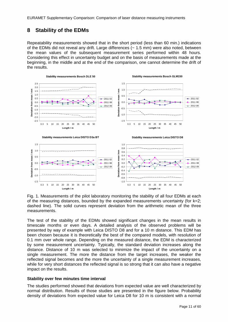
EURAMET Supplementary Comparison Comparison of laser distance measuring instruments
Page 12 of 60
distribution with standard deviation s = 019 (blue marks ndash experimental red line ndash fitted model)
-10 -9 -8 -7 -6 -5 -4 -3 -2 -1 0 1 2 3 4 5 6 7 8 9 10
dx 01 mm
Fig 2 Distribution of results over few minutes time interval
Stability over tens of minutes time interval
Several series of measurements were made with a duration from 15 minutes to 30 minutes at a constant distance and under constant measurement conditions For most of the series changes in the average value of indications of EDMs have been observed at the level of about 02 mm However for one of the series change exceeds 05 mm (see figure below) This value leads to u = 015 mm
-06
-04
-02
0
02
04
06
08
1
0 5 10 15 20 25 30
t min
dx
mm
Fig 3 Stability of results over tens of minutes time interval
Stability in the timescale of days and months
The measurements were performed in three series of measurements over an interval of a few days The cycle of measurements was repeated twice within a few months The first three measuring series were carried out in February 2011 then in August 2011 and the last one in September 2012
In the figure below the standard deviations of individual measurements of distance are shown with error bars The dashed lines represent minimum and maximum values of individual measurements in the series of measurements
EURAMET Supplementary Comparison Comparison of laser distance measuring instruments
Page 13 of 60
Leica DISTO D8 (interval 010 m)
-06
-04
-02
00
02
04
06
08
10
12
14
series
devi
atio
n fro
m n
omin
al le
ngth
m
m
Fig 4 Results of all series of measurements for Leica DISTO D8 for a distance of 10 m
Having analyzed the graph one can see that the maximum and minimum values in each series performed at an interval of several months do not overlap The mean value in one of the series is not even in a range limited by minimum and maximum for the other series
Such a large differences between the average values appear over a time scale longer than few days This means that the laboratory couldnrsquot observe this variability when briefly examining the instrument
In the figure below probability density of all results from all measurement series was presented
-10 -5 0 5 10 15 20
dx 01 mm
Fig 5 Distribution of all results from all measurement series
Continuous red curve represents the sum of the theoretical normal distributions for each series of measurements Theoretical curve is consistent with the observed distribution
max (x1x9)
min(x1x9)
di
201102 201108 201209
EURAMET Supplementary Comparison Comparison of laser distance measuring instruments
Page 14 of 60
Estimation of uncertainty of artifact
The reproducibility of EDM is affected by random changes of mean values in time scale of days To determine di for a given EDM and a given distance the results from all nine series of measurements )( 91 xx were used
)min()max( 9191 xxxxdi minus=
where i is an index of measurement distance
Set of eleven di was determined for each EDM The figure below presents those results
0
05
1
15
2
25
0 5 10 15 20 25 30 35 40 45 50
Length m
d i
mm
DLE 50
GLM 150
D3s BT
Leica D8
Fig 6 di values for all distances for each EDM
The value of di varies widely This is especially noticeable in Bosh DLE 50 where for the neighboring distances the di values can differ by several times Each EDM is characterized by a different trend
The model assumes that long-term stability is characterized by rectangular distribution with domain described by maximal di and expected value estimated based on all of the measurements Dispersion of individual measurements (short-term stability) is described by normal distribution
The max value of di was used to estimate uncertainty u(dart) related to random changes of EDM results In order to disentangle u(dart) one should try to subtract the observed short term stability from max(di) and influences of the different alignments like zero point uzero cosine error ucos and parallelism uparal [3]
( ) 22cos
2
2
art2
32
)max(paralzero
i uuud
du minusminusminus
=
In the case of Leica DISTO D8 we obtain max(di) = 1133 which corresponds to u(dart) = 0324 mm
Table below contains values of u(dart) estimated for all the four EDMs
EURAMET Supplementary Comparison Comparison of laser distance measuring instruments
Page 15 of 60
Table 6 Values of u(dart) for all the four EDMs
EDM u(dart) (mm)
Bosch DLE 50 0308
Bosch GLM 150 0197
Leica DISTO D3a BT 0149
Leica DISTO D8 0324
Additional stability test of EDMs
The suspected main factors responsible for the change of EDMs indications are 1) Effects of electronics ndash resulting from unstable operation of the EDM 2) Effects of mechanics ndash impact of transport of the EDM between laboratories 3) Effects of geometry ndash alignment repeatability of the EDM during measurements
Two additional experiments were conducted in order to determine which factors have the greatest impact on the results Leica DISTO D3a BT was used for these tests
a) Static test
During the measurements the EDM was immobilized on a bench Measurements were made at a distance of 10 m in a controlled environment The measurement results are presented in the figure below
-04
-03
-02
-01
00
01
02
03
04
1 2 3 4 5 6 7 8 9 10 11 12 13 14 15 16 17 18 19 20
measure
dx
mm
Fig 7 Static stability test results
Each point represents the mean value of 15-20 measurements This test covers about 6 hours of EDM work The standard deviation is s = 009 mm
b) Dynamic test
Measurements were made at a distance of 10 m in a controlled environment After each series of measurements the EDM was removed from the bench shaken and squeezed The aim was to simulate the conditions during transportation This test covers about 6 hours of EDM work Measurement results are presented in the figure below
EURAMET Supplementary Comparison Comparison of laser distance measuring instruments
Page 16 of 60
-04
-03
-02
-01
00
01
02
03
04
1 2 3 4 5 6 7 8 9
measure
dx
mm
Fig 8 Dynamic stability test results
The standard deviation for this test is s = 015 mm and is greater than in the static test
The average standard deviation of three measurement series was estimated using the data from the comparison The value s = 009 mm is similar to the result in the static test
The estimated uncertainty associated with the artifact for this EDM is uart = 015 mm (see table above) The same value u = 015 mm was estimated from the stability test in the scale of tens of minutes Both values are close to the value of standard deviation for the dynamic test
These results may lead to the conclusion that the level of the effects of electronics mechanics and geometry have a similar impact on the long-term stability Due to this fact it is difficult to identify which of these factors has the greatest impact on the observed measurement results
EURAMET Supplementary Comparison Comparison of laser distance measuring instruments
Page 17 of 60
9 Reference values The standard approach is to use weighted mean for determining the reference value xref [12] This is calculated by the mean of all measurement values xi weighted by the inverse square of the standard uncertainties u(xi) associated with the measurements and using these values the largest consistent subset of the sample is determined However checking the consistency of the sample without taking into account the uncertainty associated with the artifact leads to erroneous recognition of the consistent subset We propose to add uart to the uncertainty of each laboratory at the beginning of the calculation
( ) )()( 222iartic xuduxu +=
Thereby the uncertainty associated with the artifact will be taken into account during the consistency check
sum
sum
=
==n
i ic
n
i ic
i
ref
xu
xu
x
x
12
12
)(
1
)(
The pilot laboratory contributed only by its first measurements to the reference values The weighted mean approach requires the individual uncertainties from the laboratories to be estimated according to a common approach (as they should be since all participants were requested to estimate the uncertainties according to the ISO Guide) The standard uncertainty u(xref) of the reference value is calculated by combining the individual uncertainties
sum=
=n
i ic
ref
xu
xu
12
2
)(
1
1)(
The χ2 test was applied in order to estimate xref from the largest consistent subset [1]
EURAMET Supplementary Comparison Comparison of laser distance measuring instruments
Page 18 of 60
Table 7 Reference values and associated standard uncertainties based on weighted mean
Distance Bosch DLE 50 Bosch GLM 150 Leica DISTO D3a BT
Leica DISTO D8
mm xref u(xref) xref u(xref) xref u(xref) xref u(xref)
300 299694 0138 300475 0084 300353 0071 300177 0113
5000 4999900 0139 4999774 0090 5000020 0074 4999659 0111
10000 10000041 0146 9999776 0096 10000285 0077 10000336 0114
15000 14999945 0154 14999781 0120 15000176 0080 15000258 0117
20000 19999804 0175 19999423 0124 20000112 0086 20000581 0118
25000 24999955 0186 24999526 0128 25000321 0094 25000754 0124
30000 29999586 0193 29999956 0138 30000140 0103 30000675 0129
35000 34999779 0235 35000051 0156 35000022 0119 35000844 0153
40000 40000185 0279 40000250 0159 40000476 0132 40001167 0151
45000 44999576 0315 45000208 0165 45000391 0155 45000974 0156
50000 49999983 0324 50000344 0169 50000319 0156 50001137 0157
EURAMET Supplementary Comparison Comparison of laser distance measuring instruments
Page 19 of 60
10 Deviations from reference values The following figures show results from NMIs for all of the distances Reference value is represented by a bold black line
Bosch DLE 50
-30
-25
-20
-15
-10
-05
00
05
10
15
20
25
30
0 5 10 15 20 25 30 35 40 45 50 55
Length m
Dev
iatio
n fr
om n
omin
al le
ngth
m
m
MIKES
SP
Metrosert
PTB
CMI
SMU
INM
INRIM
CEM
BEV
JV
METAS
GUM
Ref
Bosch GLM 150
-20
-15
-10
-05
00
05
10
15
20
0 5 10 15 20 25 30 35 40 45 50 55
Length m
Dev
iatio
n fr
om n
omin
al le
ngth
m
m
MIKES
SP
Metrosert
PTB
CMI
SMU
INM
INRIM
CEM
BEV
JV
METAS
GUM
Ref
Fig 9 Deviations from reference values
EURAMET Supplementary Comparison Comparison of laser distance measuring instruments
Page 20 of 60
Leica DISTO D3a BT
-20
-15
-10
-05
00
05
10
15
20
0 5 10 15 20 25 30 35 40 45 50 55
Length m
Dev
iatio
n fr
om n
omin
al le
ngth
m
m
MIKES
SP
Metrosert
PTB
CMI
SMU
INM
INRIM
CEM
BEV
JV
METAS
GUM
Ref
Leica DISTO D8
-20
-15
-10
-05
00
05
10
15
20
0 5 10 15 20 25 30 35 40 45 50 55
Length m
Dev
iatio
n fr
om n
omin
al le
ngth
m
m
MIKES
SP
Metrosert
PTB
CMI
SMU
INM
INRIM
CEM
BEV
JV
METAS
GUM
Ref
Fig 9 Deviations from reference values (continued)
The deviations Di from reference value xref are calculated by
refxxD ii minus=
For calculating the expanded uncertainty of these deviations U(Di) the corresponding uncertainties u(xi) and u(xref) cannot simply be geometrically added because the values xi and xref are correlated Due to the random changes described in section 6 uncertainty u(dart) was added [2] It can be shown that the expanded uncertainty U(Di) is given by
)()()(961)( art2
ref22 duxuxuDU ii +minus=
when xi belongs to the largest consistent subset and
)()()(961)( art2
ref22 duxuxuDU ii ++=
EURAMET Supplementary Comparison Comparison of laser distance measuring instruments
Page 21 of 60
otherwise The deviations from the reference values are given in various figures and tables below The uncertainty bars in the figures correspond to the expanded uncertainties U(Di) (k = 196)
Fig 10 Deviations from reference values
EURAMET Supplementary Comparison Comparison of laser distance measuring instruments
Page 22 of 60
Fig 10 Deviations from reference values (continued)
EURAMET Supplementary Comparison Comparison of laser distance measuring instruments
Page 23 of 60
Fig 10 Deviations from reference values (continued)
EURAMET Supplementary Comparison Comparison of laser distance measuring instruments
Page 24 of 60
Fig 10 Deviations from reference values (continued)
EURAMET Supplementary Comparison Comparison of laser distance measuring instruments
Page 25 of 60
Fig 10 Deviations from reference values (continued)
EURAMET Supplementary Comparison Comparison of laser distance measuring instruments
Page 26 of 60
Fig 10 Deviations from reference values (continued)
EURAMET Supplementary Comparison Comparison of laser distance measuring instruments
Page 27 of 60
Fig 10 Deviations from reference values (continued)
EURAMET Supplementary Comparison Comparison of laser distance measuring instruments
Page 28 of 60
Fig 10 Deviations from reference values (continued)
EU
RA
ME
T S
upplementary C
omparison C
omparison of laser distance m
easuring instruments
P
age 29 of 60
Table 8 Deviations from the reference value (given at the top of the table) and expanded uncertainties (k=196) of such deviations for BOSCH DLE 50
Table 9 Deviations from the reference value (given at the top of the table) and expanded uncertainties (k=196) of such deviations for BOSCH GLM 150
EU
RA
ME
T S
upplementary C
omparison C
omparison of laser distance m
easuring instruments
P
age 30 of 60
Table 10 Deviations from the reference value (given at the top of the table) and expanded uncertainties (k=196) of such deviations for Leica DISTO D3a BT
Table 11 Deviations from the reference value (given at the top of the table) and expanded uncertainties (k=196) of such deviations for Leica DISTO D8
EURAMET Supplementary Comparison Comparison of laser distance measuring instruments
Page 31 of 60
11 En Tables Results with En gt 1 are marked with red color in Tables below En values are calculated by Di U(Di) with Di and U(Di) as given on page 19
Table 12 BOSCH DLE50
Lab Distance (mm) 300 5000 10000 15000 20000 25000 30000 35000 40000 45000 50000
MIKES -058 017 -019 -023 035 -002 -096 SP 020 019 006 005 009 059 064 037 028 097 001
Metrosert -030 -031 -003 018 032 PTB 001 029 022 -006 011 -036 001 -023 -075 -083 001 GUM -033 -005 -018 -009 000 006 017 005 -026 -028 019 CMI -003 020 -009 004 005 -022 028 SMU 006 -049 -034 -023 -017 -057 051 039 021 INM 032 031 037 006 020 005 -079 -119 -272 -260 -269
INRIM 025 -013 000 096 CEM -032 -022 -041 -039 -004 -038 080 001 -094 -047 BEV -010 007 000 -001 008 -011 037 013 -001 008 -001 JV -019 -016 025 -055 055 060 068 163 122 060 089
METAS 038 012 -005 007 -107 004 -024 002 -070 037 -052
Table 13 BOSCH GLM150
Lab Distance (mm) 300 5000 10000 15000 20000 25000 30000 35000 40000 45000 50000
MIKES 005 -002 019 018 027 019 062 SP 003 068 029 023 051 008 015 016 -005 -001 038
Metrosert -061 -011 -022 -021 -003 PTB 066 074 062 062 034 053 047 048 047 091 064 GUM -007 -014 007 -018 000 023 020 033 014 032 038 CMI -057 -032 -030 -064 -050 -047 000 SMU 023 -024 -060 012 062 001 -003 050 047 INM -022 017 -003 002 -003 054 005 -006 016 -022 -055
INRIM 079 -052 -050 -026 -034 -042 CEM 002 002 -034 -020 -029 -077 -077 -077 -074 -104 BEV -004 -002 -007 010 -042 -042 -029 -011 -028 -022 -030 JV 003 015 040 011 -020 021 -029 -005 028 036 058
METAS -047 -020 005 002 -012 -033 -054 -065 -053 -082 -040
Table 14 Leica DISTO D3a BT
Lab Distance (mm) 300 5000 10000 15000 20000 25000 30000 35000 40000 45000 50000
MIKES 008 094 050 -011 028 051 045 SP 033 038 056 017 053 065 076 051 017 071 011
Metrosert -060 -004 -037 -014 -002 PTB 067 000 070 030 089 062 061 081 124 050 072 GUM 023 019 035 008 038 053 029 058 070 064 063 CMI -001 -004 027 -011 011 034 -033 SMU 002 -013 -019 007 -013 -055 045 -013 -042 INM 002 -039 -058 001 002 -045 -080 -051 -102 -101 -378
INRIM 070 -020 063 101 CEM -028 -004 -004 -064 003 -002 -050 -022 -093 -160 BEV -032 -019 -019 004 -011 -037 -017 -002 -025 005 012 JV 027 019 027 042 046 039 043 048 072 115 024
METAS -091 -008 -102 -098 -111 -103 -092 -080 -073 -108 -043
EURAMET Supplementary Comparison Comparison of laser distance measuring instruments
Page 32 of 60
Table 15 Leica DISTO D8
Lab Distance (mm) 300 5000 10000 15000 20000 25000 30000 35000 40000 45000 50000
MIKES 025 013 058 036 038 061 022 SP 057 026 040 016 013 016 025 017 -007 -019 007
Metrosert -021 006 -016 -043 -019 PTB 040 011 035 -005 -011 -002 -004 035 047 022 069 GUM -028 005 -025 031 039 -015 029 048 041 052 072 CMI -104 -026 -072 -057 -006 -017 -015 SMU -067 -017 -051 -026 -016 -054 -004 -001 -016 INM 021 -014 009 003 -017 -031 -010 007 029 036 041
INRIM 076 -024 -004 047 -007 083 CEM 004 -009 002 -033 -051 -059 -097 -077 -116 -134 BEV -057 -014 -051 -093 -024 -027 -021 -036 -038 -028 -041 JV 014 031 047 030 044 043 035 056 093 108 030
METAS 035 007 026 038 -013 -024 -011 -048 -089 -074 -066
12 Conclusions It was the first comparison of EDMs For most of the laboratories it was an important opportunity to validate their measurement instrumentation and procedure It allowed to become aware of potential problems and to take corrective actions in changing the procedure
For the evaluation of the reference value the weighted mean approach has been chosen although the consistency check according to procedure A of Ref [1] failed in many cases A more complicated procedure for the evaluation of the reference value was proposed which slightly changes the uncertainty of the reference value
In total there were 23 En values larger than 1 This represents 47 of the full set of 482 results It is less than the 5 of possible values being out of the expanded uncertainty of the reference value for k=2
The uncertainty of the results mainly comes from the uncertainty of the reproducibility It is difficult to distinguish between Labrsquos calibration and measurement capability
The comparison shows a global compliance with declared CMCs independently of whether some participant can have a high percentage of values not compliant with its CMC due to the influence of the artifact and the estimation of its uncertainty
13 References [1] M G Cox The evaluation of key comparison data Metrologia 39 589 ndash 595 (2002)
[2] R Thalmann EUROMET 677 ndash Steel Tape Measures Final report (2004)
[3] F Pollinger personal communication
EURAMET Supplementary Comparison Comparison of laser distance measuring instruments
Page 33 of 60
Appendix 1 Description of the measurement equipmen t as reported by the laboratories
A11 MIKES Finland
Short description of measurement bench
MIKES interferometric bench is situated in an underground laboratory with air temperature and humidity control Typically air temperature is 20 plusmn 01 degC and humidity 45 plusmn 2 RH The linear guide on the top of the concrete beam comprises two parallel round shafts with adjustable fixtures every 1 m A carriage with ball bush bearings is moved along the rail and location of it is measured with reference interferometer HP-5529A Temperature of air is measured with 6 pt100 sensors and Keithley 2010 multimetre with 4-wire resistance mode Air pressure and humidity are measured with Vaisala PTU200 Updated Edleacuten equation by Boumlnsch amp Potulski is used for calculation of refractive index of air
For EDM calibration on the other end than laser interferometer is a fixed reference plate which is adjusted perpendicular to the laser beam Next to the reference plate is an adjustable base for EDM instrument with which it can be adjusted to point parallel and coincident with measurement arm of the interferometer A target plate adjusted perpendicular to laser beam is fixed to the carriage The calibration followed Abbe principle with some millimetre uncertainty in offset adjustment
First reference interferometer is set to zero when the target plate and reference plate are in contact then EDM is positioned and adjusted in its base The rear surface of the EDM is also slightly pressed against reference surface behind it Then the readings from both instruments are collected at selected locations For this calibration there is no fine adjustment of the target position so there are typically deviations of up to few millimetres from nominal locations Results are averages of 3-4 measurements
Additional remarks
The CMC entry MIKES has for EDM calibrations is based on calibration of length scales of high quality total stations and laser trackers This type of EDMs used in this comparison are not accurate enough for truly testing of MIKES calibration measurement capability
EURAMET Supplementary Comparison Comparison of laser distance measuring instruments
Page 34 of 60
A12 SP Sweden
Short description of measurement bench
The bench consists of a simple aluminium Uminusshaped profile with polished steel pins acting as supports for the tape The bench is a little over 50 m long and works as support for the reference tape and the calibrated EDMs simultaneously
Length measurement instrument
Comparison with reference steel tape
Temperature measurement system number and location of sensors
The tape temperature is continuously registered in 6 points equally distributed along the bench The air temperature is monitored during the measurements but not used for corrections
Additional remarks
The EDM support is placed approximately 2 cm vertically above the tape No visual aid is used
EURAMET Supplementary Comparison Comparison of laser distance measuring instruments
Page 35 of 60
A13 AS Metrosert Estonia
Short description of measurement bench
The 21-m bench is located in the designated corridor-like laboratory room The lab is air-conditioned and the stability of temperature is typically plusmn05 ordmC There are three humidity and temperature sensors in room for stability and gradient monitoring
Two stainless steel rails running in parallel are made of 3-m long rods The rails lay without fixed attachment on metal supports which are mounted on concrete base The base rests on pillars made of bricks
Length measurement instrument
Laser-interferometer system Renishaw ML10 was used as length measurement instrument
Laser interferometer gets temperature humidity and pressure data from itrsquos own measurement system EC10
Additional remarks
Due to the length of the bench only measurements up to 20 m could be made Five measurement series were made with each EDM
EURAMET Supplementary Comparison Comparison of laser distance measuring instruments
Page 36 of 60
A14 PTB Germany
Short description of measurement bench
The measurements were performed on the 50 m geodetic base of the PTB The comparator consists of a 50 m rail The laboratory is equipped with a network of 21 temperature sensors spaced by 25 m along the bench As depicted in fig 1 the EDM is mounted at one end of the comparator the reflector is fixed vertically on the carriage A large retroreflector is mounted approximately 150 mm below the EDM reflector on the carriage reflecting the beam of the reference interferometer The deviation of the length due to tilting carriage (Abbe error) has been investigated along the bench by comparison of two interferometers It remains smaller than 100 microm The distance of the first position of 300 mm with respect to the back side of the EDM is determined by a gauge block of 300 mm length and a thickness of 10 mm This procedure is depicted for one of the comparison standards in figure 2
For the calibration the desired positions are programmed After the carriage reaches a measurement position the operator waits for another 30 s for the carriage to settle In control experiments the remaining movement between positioning and measurement remained smaller than 2 microm The operator then activates the measurement of the EDM reads the indicated position and writes it down The procedure is repeated for twelve times at every position the mean of the 12 measurements represents the ldquoindicated distance by the EDMrdquo All measurements of a single run at one position are performed within approximately one minute The complete measurement was repeated for four times
Length measurement instrument
The reference length is determined by a frequency-calibrated laser interferometer (Agilent 5519A) The reference interferometer is set up in Michelson geometry the signals being digitalised by a Heidenhain IK 121 card The index of refraction is determined by the external weather station of the geodetic base consisting of 21 Pt-100 temperature sensors spaced 25 m along the bench two humidity sensors (Testo 650) and two pressure sensors (Setra 370 and DPI 141) The environmental parameters are used to determine the index of refraction for the reference measurement deploying the modification of the Edleacuten equation by Boumlnsch and Potulski
EURAMET Supplementary Comparison Comparison of laser distance measuring instruments
Page 37 of 60
A15 CMI Czech Republic
Description of measurement bench
The EDMs were measured on 30 m long measuring bench equipped by laser interferometer (LI) Renishaw ML10 (pic 1 and 2) calibrated traceable to national standard of length and quantities of environmental sensors The target plate and retroreflector of the LI were fixed on a moving part of the bench and each EDM was fixed in horizontal position by clamps (pic 3) LI and EDM are placed on opposite ends of bench the Abbe offset was lt10 mm for some of them and lt50mm for all The value of LI was reset (to zero) at position corresponding to the rear of the EDM (using 3D measuring arm FARO Quantum with uncertainty about 27microm) The perpendicularities of the EDM stop as well as target plate to the beam were also checked by FARO) Each EDM was 3x replaced and aligned the measurement (reading) was repeated 6 times for each alignment and position the mean value of these 3x6 measurements is stated in tables with results The uncertainty claimed covers the statistical uncertainty of single readings Only in case of Leica D8 (the best performing EDM in this comparison) we state also the uncertainty corresponding to the mean of 6 readings in last column (this uncertainty is smaller and better illustrates our CMC)
Length measurement instrument
- Laser interferometer Renishaw - Laser 633 nm Type ML10 - Compensator EC10 - 3D measuring arm FARO Quantum - 3D measuring arm FARO Quantum
EURAMET Supplementary Comparison Comparison of laser distance measuring instruments
Page 38 of 60
A16 SMU Slovakia
Short description of measurement bench
No bench is available at the SMU the measurements are being carried out in the underground corridor of the laboratory building with length of 428 m
The 50 m steel measuring tape KINEX was used as the reference laid on the floor and pulled by the force 50 N (the same force as had been applied during its calibration at the SMU) The calibration of reference tape was done at the SMU using ULM3m Zeiss with laser interferometer Agilent 5529 B (ie per 3 m parts)
Three mercury thermometers with the resolution of 01 degC were used along the measurement path each of them laid onto the tape and located at 667 m 1990 m (instead of 20 m because of this was one of measuring points) and 333 m respectively Each of them thus corresponded approximately to one third of the measured steel tape section
Regarding the 03 m measuring point the ULM3m Zeiss length measuring machine was used with the 300 mm gauge block as the reference
Length measurement instrument
We used our own target plate being fixed perpendicularly (within uncertainty stated) to the construction equipped with nonius and the camera holder transported manually along the steel tape The second construction was fixed to the tape by such a way that zero line of the tape corresponded to the rear of EDM (within uncertainty stated)
The position of the target is read on the monitor and 20 repeated readings of the EDM data took place in each measuring point (multiples of 5 m up to 40 m)
Concerning 03 m the 300 mm gauge block was fit between the target plate and the construction with EDM The distance of the EDM rear from the target plate corresponded to the length of gauge block (within uncertainty stated)
Additional remarks
The identical measurement method was used as we use to do within our calibration service although the results reporting is different ndash we provide the regression line calculated from the measurement of irregularly distributed points and corresponding uncertainty (k = 2) in the form of [a bL] mm (ie the same coefficients for each length in the range (0 ndash 42) m)
SMU hasnrsquot got this category in CMC tables
EURAMET Supplementary Comparison Comparison of laser distance measuring instruments
Page 39 of 60
A17 INM Romania
Short description of measurement bench
Geodesic base located in the basement of the laboratory with nominal length equal to 50 m having a mobile carriage thet support both laser He-Ne retroreflector and the target of the laser distance measuring instrument in the front of geodesic base exists a support where are aligned both laser interferometer and the laser distance measuring instruments
Length measurement instrument
Laser interferometer type Hewlett Packard model 5526 A with nominal length equal to 50 m resolution 0001 mm
U = 02 microm +0510-6L
Additional remarks
During the measurements the maximum gradient of temperature was equal to 05 degC
EURAMET Supplementary Comparison Comparison of laser distance measuring instruments
Page 40 of 60
A18 INRIM Italy
Short description of measurement bench
The facility for long distance measurements is located in a corridor of the gallery devoted to dimensional metrology The structure consists in a 28 m long rail fixed to a series of pillars which rest directly on the ground released from the vibrations of floor and wall The measuring system is based on a heterodyne interferometer whose mobile arm consists of a hollow retro-reflector mounted on a structure that can run along the rail so-called carriage A photograph of the facility is presented in Fig1
The carriage is moved by a micro-step motor the motor driver receives a digital pulse and converts it into an electrical pulse to run the motor Each pulse causes a rotation of the motor shaft of one step which amounts to 11000 of a complete revolution of the shaft If the pulse frequency increases the rotation becomes continuous with a speed that is directly proportional to the pulse frequency The speed ranges between few microms up to 27 ms with a resolution of 03 microms
Since the carriage must move back and forth automatically for a distance of almost 30 m a remote control to send pulses to the motor driver was implemented It consists of two parts a radio command which allows to set some general parameters of the carriage movement such as the movement direction and mode of travel (slow or fast) and a fast command which is performed by an amplitude modulated laser beam placed at the beginning of the track oriented towards the carriage A photo detector placed above the carriage receives the modulated laser beam which is transformed into pulses to be sent to the driver of the motor The modulation of the laser beam is implemented by a LabView program that controls a digital output of the data acquisition device
Length measurement instrument
The length measurement instrument is based on a heterodyne incremental interferometer The main beam of the interferometer with frequency f1 is generated by a frequency stabilized
EURAMET Supplementary Comparison Comparison of laser distance measuring instruments
Page 41 of 60
He-Ne laser calibrated with respect to the INRIM length standard and sent to the measurement arm the second beam is a portion of the first one diffracted by an acousto-optic modulator (AOM) with frequency f2 = f1 + 80 MHz The reference detector acquires the beat note signal at 80 MHz while the measurement detector acquires a signal at 80 MHz whose phase is varied due to the displacement of the retro-reflector moving on the rail In figure 2 the optical design of the interferometer is presented
Two different measuring techniques have been implemented
1 the ldquophase measuringrdquo technique based on fringes counting with a relative uncertainty of 5middot10-7 but limited at the maximum carriage speed of 3 cms
2 the ldquoDoppler frequency measurementrdquo technique for higher carriage speed based on the measurement of the Doppler frequency shift while the carriage runs
The second technique was validated by means of the comparison with the first technique at low speed with an agreement of the order of 3middot10-6 hence the Doppler frequency method could be considered validated within 01 mm over the whole rail path with the advantage of reducing the time needed to cover long distances so it was used for the EDM comparison
In order to obtain the distance covered by the carriage according to technique 2 the Doppler frequency is measured by a commercial high-performance counter (a Pendulum CNT-90) without dead time based on time stamping then it is converted in speed and integrated over time according to the following formula
( ) ( )int minus=minus= tffn
dtn
ffdairair
λλ
2
1
2
1
where d is the distance covered by the carriage f is the frequency of the measuring signal with the carriage at rest frsquo the frequency of the measuring signal with the carriage moving λi
is the wavelength of the laser in vacuum n - air is the air refractive index and ti is the integration time The difference frsquo-f is just the Doppler frequency due to the moving carriage
The time interval measurement resolution of the instrument is 100 ps and the time base is
EURAMET Supplementary Comparison Comparison of laser distance measuring instruments
Page 42 of 60
connected to the INRIM UTC so that the measurements of the Doppler frequency and the integration time are extremely accurate The environmental parameters such as air temperature atmospheric pressure partial pressure of water were monitored during the measurement process in order to calculate the value of air refractive index according to the Edlenrsquos formula
Comparison set-up
The different technical solutions adopted for the EDMs and for the target plate positioning are discussed in this paragraph and sketched in figure 3
Fig 3 picture of the EDM and target positioning area
Target plate positioning
In order to use the provided target plate an ad-hoc mounting was manufactured at INRIM it consists in a sort of picture frame made in aluminum which slightly clamps the target folded in half and gives it the necessary stiffness to be a reproducible target The upper part of the frame is L-shaped and allows it to be fixed to the carriage structure by means of two screws The rear part of the target mounting is depicted in figure 4 The target mounting was considered necessary because of the poor stiffness and planarity of the plastic target With the aluminium frame a planarity better than 01 mm was guaranteed The target plate is placed few centimetres next to the retro-reflector and normal to the interferometer beam axis since the EDM laser should be as close and parallel as possible to the reference beam
EURAMET Supplementary Comparison Comparison of laser distance measuring instruments
Page 43 of 60
Fig 4 picture of the rear part of the target plate mounting
EDMsrsquo positioning
The EDMs are placed on a cradle-like platform which is able to adjust the inclination of the EDM along the longitudinal axis (pitch angle) The platform height allows the EDMs to be at approx the same height as the interferometer beam A crucial role was played by the stop-wall placed behind the platform since it represents the ldquozero pointrdquo for all the length measurement Hence a particular effort was devoted to align the stop-wall so that it was normal to the interferometer beam axis and parallel to the target plate
Fig 5 detail of EDMsrsquo positioning the cradle-like platform and the stop-wall are well visible
EURAMET Supplementary Comparison Comparison of laser distance measuring instruments
Page 44 of 60
Target and stop-wall alignment
In order to have the stop-wall parallel to the target plate and normal to the interferometer beam axis the following procedure has been used
1) the stop-wall and the target plate were roughly placed trying to set them parallel and normal to the rail by eye (ie within few millimeters)
2) in order to check if the target was normal to the rail one EDM was positioned on the platform the pitch and yaw angles of the EDM were adjusted by observing the position of the EDM laser spot on the target plate when the target is moved along the rail fixed position means laser beam parallel to the carriage movement Then the target was moved until the end of the rail and a thin mirror was kept in contact with it hence observing the EDM laser reflected by the mirror it was possible to adjust the target tilt acting on the screws until the laser beam is reflected back to the source
3) finally in order to check the parallelism between the stop-wall and the target a tool made by a laser pointing orthogonally to its base was used the base was leant against the stop-wall and the laser was centered on the target when the target is near then the target was moved until the end of the rail hence observing the spot of the laser on the target it was possible to adjust the stop-wall orientation
The residual misalignment errors which we were not able to eliminate were kept into account in the uncertainty budget
Measurement of the first 30 cm
Due to the geometry of our set-up it was not possible to perform the first point of measurement by means of the interferometer indeed the carriage (hence the target) is not able to go in contact with the stop-wall
Fig 6 measurement of the first 30 cm the ruler touching the stop-wall and the target and the mechanical probe (in the back) touching the carriage are visible
EURAMET Supplementary Comparison Comparison of laser distance measuring instruments
Page 45 of 60
So a ruler made of aluminum with rounded ends and nominal length equal to 30 cm was adopted to set the distance between the target plate and the stop-wall for the first point of measurement as it is shown in figure 6 The ruler whose length was measured by a CMM machine was inserted between the target and the stop-wall leaning against the latter and the carriage was carefully moved towards the stop-wall until the target lightly touched the ruler A mechanical probe that touches the carriage structure when carriage is in the ldquo30 cmrdquo position was used as a reference measurement to check the repeatability of this distance after each measurement set
Fig 7 detail of the mechanical probe touching the carriage
Environmental parameters
The environmental parameters such as air temperature atmospheric pressure and humidity were monitored during the whole measurement process in order to calculate the value of air refractive index according to the Edlenrsquos formula
Among these parameters the temperature distribution along the mobile arm of the interferometer was our main concern mainly for two reasons
1 the temperature control of the gallery was not perfectly working during the measurement period so temperature drifts had to be monitored
2 longitudinal temperature gradients due to non uniform heating and to the presence of electronic instruments were pretty high
To the purpose 14 thermometers were uniformly dislocated along the rail and automatically recorded for all the measurement period Both temporal drifts and gradients along the path have been taken in account in the uncertainty budget In any case maximum temperature differences along the rail are within 1 degC In fig 8 an extract from the acquisition file is shown
Unfortunately the air conditioning system did not work well during the measurement campaign hence the measurements were performed at a mean temperature of 209 degC
EURAMET Supplementary Comparison Comparison of laser distance measuring instruments
Page 46 of 60
Fig 8 each curve represents the temperature distribution along the rail during the measurements campaign
Carriage waving
Since the rail is not perfectly straight and the measurement laser is not coincident with the measurement beam the Abbegrave error due to waving of the target must be considered A quantitative measurement and a qualitative measurement were carried out With an electronic level placed on the carriage the straightness on the vertical plane has been mapped with a half meter resolution (the data are reported in fig 9) With a laser placed on the carriage the horizontal and vertical waving are qualitatively compared by looking at the movements of the light spot on a target fixed to the rail end As a conclusion the horizontal and vertical waving are comparable in magnitude and the peak to peak error is of the order of 300 arcseconds
Fig 9 vertical waving of the target measured by an electronic level placed on the carriage
EURAMET Supplementary Comparison Comparison of laser distance measuring instruments
Page 47 of 60
Measurement procedure
The measurements were carried out according to the following procedure
The target was set in the starting position with the procedure described above
In sequence the four EDMs are positioned on the base the horizontal and vertical tilt are adjusted and the distance measurement is recorded An additional fifth EDM (Bosh DLE 150 property of INRiM) was included in the measurement sequence Each EDM is placed on the base and gently pushed against the reference wall in such a way that the measurement laser beam starting point is the same for all EDMs Than the horizontal and vertical angles were adjusted in order to hit the central point of the target indicated with two black marks (see pictures 3 and 6) with ldquovisualrdquo alignment The measurement button is then pressed several times (typically 5) and the average reading is recorded Typical dispersion between readings is within few last digit units In case the dispersion between readings is too large the anomaly is recorded
The carriage was then moved in the next position (about 5 m) and the measurement sequence was repeated for the 5 EDMs The operation is repeated up to 25 m The 25 m measurement is than repeated again as well as all the points till the first one so that each point is measured twice each set Since the carriage movement is ldquoopen looprdquo the positioning of the carriage was not exactly in the nominal 5 m intervals For each positioning the incremental displacement is measured by the interferometer in the Doppler mode Finally the measured values were averaged in order to give a single value for each nominal position
At the end of the measurement set when the carriage is at the 30 cm position again the sum of the interferometric measurements should be very close to zero The residual value is compared with the difference between the first and the final measurements of the mechanical probe The difference must be within the uncertainty of the Doppler technique otherwise some error occurred in the measurement set that must be repeated
At the end of the session 10 complete sets of measurements recorded from the 20th to the 30th of January 2012 have been considered for this report
Additional remarks
Effect of laser pointing
During a preliminary set of measurements we noticed a strong and unexpected dependence of the measurement result on the position of the laser spot on the target Indeed since no particular instructions were given about the relative position of the laser spot on target position (except to exclude the central joint between the two halves) we decided to work relatively close to the right side of the target -closer to the interferometer beam- in order to reduce the Abbegrave error We noticed very large errors at large distances in particular of the Leica DISTO D3a (see figure 10)
EURAMET Supplementary Comparison Comparison of laser distance measuring instruments
Page 48 of 60
Fig 10 errors of each EDM In a preliminary set of measurements
We also noticed that this error was strongly dependent on the position of the spot on the target For this reason we carried out a set of measurements at the maximum length in different positions of the target from one edge to the other according to figure 11 The results are reported in table V
EDM A B C D E
Leica D3a -4 +1 0 +24 +43
+2 0 +42 +40
-1 0 +38
Leica D8 0 0 0 2 +7
0 +12 +23
table V deviations (in mm) from the length measured at point C aiming the laser spot at different positions of the target (notations as in figure 11)
We tried to find an explanation to this effect in the shape of the laser spot if the spot was
EURAMET Supplementary Comparison Comparison of laser distance measuring instruments
Page 49 of 60
particularly defocused or had high diffraction some of the energy could fall out of the target and affect the measurement result In fact the images of the spots (shown in fig 12) do not support this hypothesis Finally we decided to use the center of the (half) target for the comparison
Changing the target
In order to investigate the influence of the target on the measurements a cardboard foil (400 x 400) mm was fixed to the target mounting and a complete set of measurements was performed The results reported in figure 13 and 14 do not show any evidence of a possible dependency of the EDM measurement on the target kind
EURAMET Supplementary Comparison Comparison of laser distance measuring instruments
Page 50 of 60
Measurement at 50 m
Although we are not able to perform traceable length measurements beyond 28 m we wanted to get a sense of EDMs behaviour at longer distances So a target (represented by a rack side wall) was placed at approximately 50 m one after the other the EDMrsquos were positioned on the base and pointed towards the target The measurements were repeated then the target was replaced by the target used for the comparison and a third set of measurements were performed To our great surprise all the EDMrsquos were in good agreement (within 2 or 3 mm for each set of measurement) even those which showed errors of the order of five to ten millimeters at 25 m namely BOSCH DLE 50 and LEICA DISTO D3a Therefore each set of measurements was averaged and the deviations from the mean value are reported in figure 15
EURAMET Supplementary Comparison Comparison of laser distance measuring instruments
Page 51 of 60
Fig 15 Deviations from average value of the measurements At 50 m
EURAMET Supplementary Comparison Comparison of laser distance measuring instruments
Page 52 of 60
A19 CEM Spain
Short description of the measurement bench
To make the measurements of EDMs we have used a reference line made of adjustable supports fixed on a wall of the laboratory Each support is nominally separated five metres from the previous one so we can generate reference lengths up to fifty metres with a pitch of five metres The supports are designed to accommodate both targets and handheld EDMs Distances between supports were measured by using a total station traced to national standards The relative angles of the bases have been measured and corrected
Fig 1 - View of three consecutive supports of the 50 m baseline (left) Lab technician situating an EDM on the first support of the baseline (right)
Length measurement instrument
The baseline was calibrated by using a total station Leica TDA5005 with spherical reflector the calibration uncertainty being 02 mm for k = 2
The target is provided by the comparison The quality of the target was judged as not good due to geometrical constructive errors and the lack of rigidity and stability We measured the flatness of the target surface the distance edge-surface and the angle between them by using a 3D coordinate measuring machine The results of flatness and angle were included in the uncertainty budget and the distance EDM-target was corrected for each EDM due to each beam impinged on a different point of the target
We were not able to measure the distance 0 to 03 m because the baseline pitch is 5 meters and although we are able to measure shorter values in a different facility the target was not appropriate for our bench
EURAMET Supplementary Comparison Comparison of laser distance measuring instruments
Page 53 of 60
Fig 2 - View of an EDM on the first support of the baseline (left) A closer look showing the support adjustments and the origin plate (right)
Fig 3 - View of the comparison target on one of the supports of the baseline (left) A closer look showing the target edge against the support rigid reference (right)
Measurement method
The measurements were carried out by comparison against the known values of the calibrated baseline (metallic references on supports)
Environmental conditions were maintained within the following limits
- Temperature 20 ordmC plusmn 05 ordmC
- Humidity 45 plusmn 10
Each laser distance measuring instrument was placed at the first support of the base and aligned so that the laser beam was perpendicular to the target as indicated by the comparison protocol
For each measurement we took the average of thirty measurements It permitted us to evaluate the repeatability of the instrument
EURAMET Supplementary Comparison Comparison of laser distance measuring instruments
Page 54 of 60
A110 BEV Austria
Short description of the measurement bench
Fig 1 Carriage of tape bench View from the laser interferometer side Retroreflector mounted on the vertical plate the EDM target is mounted on the backside
Fig 2 Support for the DUT Adjustable with 2 translational and 2 rotational degrees of freedom respectively
Fig 3 Setting of the 300 mm starting position Note the rough-and-ready mounted target plate
Fig 4 Laser interferometer side of the bench The DUT is 50 m away on the other side
EURAMET Supplementary Comparison Comparison of laser distance measuring instruments
Page 55 of 60
Measurement procedure 1 The EDM is positioned with the help of a 4-axis positioning stage so that its laser beam is
coaxial with the measurement direction of the laser interferometer (in head on configuration)
2 The EDM is removed from its support The bench carriage is positioned so that the distance of the target plate from the EDM back support is 300 mm A length bar with spherical faces is used for this adjustment The laser interferometer is preset to 300 mm and the EDM is put back on its support
3 At each position 10 consecutive measurements are taken (repeatability) and the carriage is moved to the next position The carriage is manually moved under control of the laser interferometer until it is within plusmn30 microm at the correct position (Exception for the DLE 150 the target is not positioned at 10 m but at 10 m ndash 1 mm to make use of the higher resolution) The indicated (not the nominal) distance of the laser interferometer is recorded for the determination of the deviation
4 After reaching the 50 m position all points are measured in reverse order (bidirectional) Immediately after the last measurement the EDM is removed and the indication using the 300 mm length bar is checked (thus noting a possible drift of the setup)
5 Each instrument was measured 4 times according to this procedure on different days (reproducibility of bench and instrument)
Length measurement instrument
Agilent laser interferometer with long range option The bench was completed short time before performing these measurement So the characterisation was not complete and the respective measurement uncertainty of the laser interferometer is estimated rather high But anyway its contribution to the overall uncertainty can nearly be neglected
Additional remarks
The uncertainty originating from the DUT is the dominating uncertainty contribution Specifically the resolution of the two Bosch instruments (1 mm) and the repeatability are the largest contributions For the DLA 50 the pooled standard deviation of a reading at 50 m is larger than 2 mm Moreover the length dependence is not a simple function
All of the instruments show a significant deviation of the laser beam from the normal of the back (reference) face of the instrument The measured angles reach from 04deg (D3a) to 11deg (DLE 50) This leads depending on the outer dimensions of the instruments to a constant uncertainty contribution of 02 mm in our setup It must be noted that the reference faces are not well defined in most of the instruments
The reproducibility is quite different for the four instruments so only part of it originates from the setup For CMC claims we will use the standard uncertainty value of the most reproducible instrument (D3a) which amounts to 013 mm For an ideal instrument with a resolution of 01 mm and perfect repeatability we would thus have a constant expanded uncertainty of 053 mm up to 50 m
EURAMET Supplementary Comparison Comparison of laser distance measuring instruments
Page 56 of 60
A111 JV Norway
Short description of measurement bench
EDM under calibration and the reference system are aligned along a 50 m measurement bench with rails to carry the linear movement of a target plate for the EDM and a corner cube reflector for the reference system The distance between parallel axis of EDM and axis of the reference system is 130 mm Abbe error due to angle errors for the movement is smaller than 01 mm and is corrected for at each measurement point At long lengths an aperture is used approximately midway between the target plate and the EDM to avoid interfering stray light to the EDM
Alignment procedure
1) Alignment of reference system to the movement of the carriage (rails)
2) Alignment of the EDM to the movement of the carriage (rails)
3) Alignment of a plane mirror at the position of the target plate using back-reflection to the EDM output (normal incident of light on the mirror)
4) Take out the EDM and align the zero reference plate at the back of the EDM to the plane mirror
5) The mirror is replaced by the target plate and the target plate is aligned to the zero reference plate
6) Zero setting of the reference measurement system when target plate is at zero distance to the reference plate at the back of the EDM
7) Put the EDM back in position and realign it to the movement of the carriage (rails)
8) Zero setting of the EDM to the reference plate
Image 1) Image 2) Image 3) Image 4)
Image 1) Items 5) ndash 6) in alignment procedure
Fixture for HP linear interferometer is seen bottom right Part of Wyler instrument is seen to the left blue colour
Image 2) Items 7) and 8) in alignment procedure
Micrometer screws for angle alignment in two directions and linear translation for zero setting of the EDM Push button on the EDM is positioned at the tilting point of the angle adjustment table to maximize stability during measurement HP 5519 A laser head is seen to the right
Image 3) Ready to measure at selected distances from zero point the reference plate
Image 4) EDM spot size at 50 m
Length measurement instrument
- Hewlett Packard Dynamic Calibrator 5519 A (max range 80 m)
- Pressure air temperature humidity Vaisala
EURAMET Supplementary Comparison Comparison of laser distance measuring instruments
Page 57 of 60
- Digital high resolution angle measurement Wyler
I used our own target plate which is of the same type as enclosed in the artefact suitcase article number 766560 from Leica but with reduced size width x hight = 90 x 137 mm
The zero reference plate is of similar type and size
Before measurements batteries of EDMs were switched to new batteries Old batteries are switched back after calibration
For L gt 5 m an aperture of similar size as the target plate is used approximately midway between the EDM and the target plate
Additional remarks
Reports on EDM indicated values at each measurement point is the average value of n = 5 repetitions A linear model of the standard deviation for the repeatability of the EDM readings at different lengths is estimated using m = 20 repetitions at least 5 positions along the scale An estimate of the length dependent repeatability is made for each instrument
The expanded uncertainty U(95) is rounded up to the limiting resolution of 1 mm in the interval 10 m to 40 m for Bosch GLM 150
After the calibration we also estimated the angle error of the optical axis of the EDM to its back plane (back reference of EDM) Bosch DLE 50 26 mrad up measured at 50 m Bosch GLM 150 8 mrad to the left measured at 50 m Leica DISTO D3a 37 mrad down measured at 20 m Leica DISTO D8 2 mrad to the left and 4 mrad down (45 mrad total) measured at 20 m
The distance between parallel walls will be measured too large if the back plane is assumed to be normal to the optical axis of the EDM by ∆LL = (1cosα ndash 1) Bosch DLE 50 ∆LL = 340 ppm (∆L = 17 mm at L = 50 m) Bosch GLM 150 ∆LL = 32 ppm (∆L = 16 mm at L = 50 m) Leica DISTO D3a ∆LL = 7 ppm (∆L = 034 mm at L = 50 m) Leica DISTO D8 ∆LL = 10 ppm (∆L = 05 mm at L = 50 m)
EURAMET Supplementary Comparison Comparison of laser distance measuring instruments
Page 58 of 60
A112 METAS Switzerland
Short description of measurement bench (photo recom mended)
50 m bench with laser interferometer (see photo detailed description in Michel Degoumois Un Long laboratoire de mesure OFMETinfo Vol5 No 2 1998)
Length measurement instrument
HP 5529 B laser interferometer range 80 m
EURAMET Supplementary Comparison Comparison of laser distance measuring instruments
Page 59 of 60
A113 GUM Poland
Short description of measurement bench
The 50 m bench is situated in the corridor laboratory located in the basement and has its own air conditioning system with air temperature 20 plusmn 1 degC and humidity 50 plusmn 10 RH The measuring carriage is carried microscope with CCD camera and the optics associated with the interferometer The carriage is driven using belt-transmission and electrical engine with remote ndash controlled variable speed drive
The EDM was placed on the fixed adjustable plate on the other end than laser interferometer The target plate of the EDM was placed on the measuring carriage For each EDM 3 series of measurement were done Before the each measurement EDM was repositioned and aligned again
Length measurement instrument
1 Laser interferometer HP 5529A with long-range option laser head HP 5519A
2 Ambient measurement system number and location of sensors - 20 air temperature sensors type YSI with KEITHLEY multimeter they are placed very
close to axis of the laser beam - air pressure and humidity are measured with Vaisala barometer and
thermohigrometer - CO2 content was measured with analyzer made by Intelli Charge type SPN 4462
EURAMET Supplementary Comparison Comparison of laser distance measuring instruments
Page 60 of 60
Appendix 2 Corrections of reports
131 CEM Spain
CEM reported two errors in their report
1) Bosch GLM 150 EDM error for 35 m should be -08 mm instead of the indicated 08 mm
2) Leica DISTO D8 EDM error for 35 m should be -019 mm instead of the indicated 019 mm
Proposed corrections have been included in Tables 2 and 4 of the Final Report
132 AS Metrosert Estonia
AS Metrosert reported mixed up of all results for Bosch DLE 50 and Bosch GLM 150 The results and uncertainties sent for DLE 50 was results for GLM 150 and vice versa
Proposed corrections have been included in Tables 1 and 2 of the Final Report
133 INRIM Italy
Among the data reported from INRIM some anomalies were found in the measurements of BOSCH DLE 50 and LEICA DISTO D3a at distances of 20 and 25 m
After preliminary discussion on Draft A it was understood that those anomalies could be explained as a sensitivity of said instruments to the laser light that once diffused by the target is reflected by surfaces parallel to the measurement axis and detected together with the wanted signal The superimposition of the two signals can cause a ldquopullingrdquo effect leading to an overestimation of the distance being the reflected path always longer than the direct one Indeed in the INRIMrsquos set-up the target was mounted pretty close to the flat rail used for the carriage movement being likely responsible for unwanted reflections that disturbed the measurements
Since the errors reported in INRIMrsquos measurements can be ascribed to a defect of BOSCH DLE 50 and LEICA DISTO D3a andor to a lack of description of the working conditions of said instruments INRIM asked to eliminate its measurement points at 20 and 25 m of said instruments from the comparison
Proposed corrections have been included in Tables 1 and 3 of the Final Report
134 JV Norway
Justervesenet has changed the procedure and introduced two apertures instead of only one aperture (iris) which was positioned at half distance between EDM and target The reason is that the reference beam also has an aperture and it is positioned right below the beam from the EDM (130 mm distance between axes) Some diffusively reflected stray light from the EDM target might enter the aperture for the reference beam reflect at the measurement table and reach the detector of the EDM In our calibration set-up we have only seen problems at L gt 30 m We will position the first aperture at ca 5 m from the EDM and then the second aperture at ca 25 m This combination of two apertures will effectively eliminate interference of stray light from the measurement table to the EDM detector for all lengths up to 50 m
Justervesenet also increases the uncertainty component regarding repeatability reproducibility so that the expanded uncertainty increases from 14 mm to 15 mm
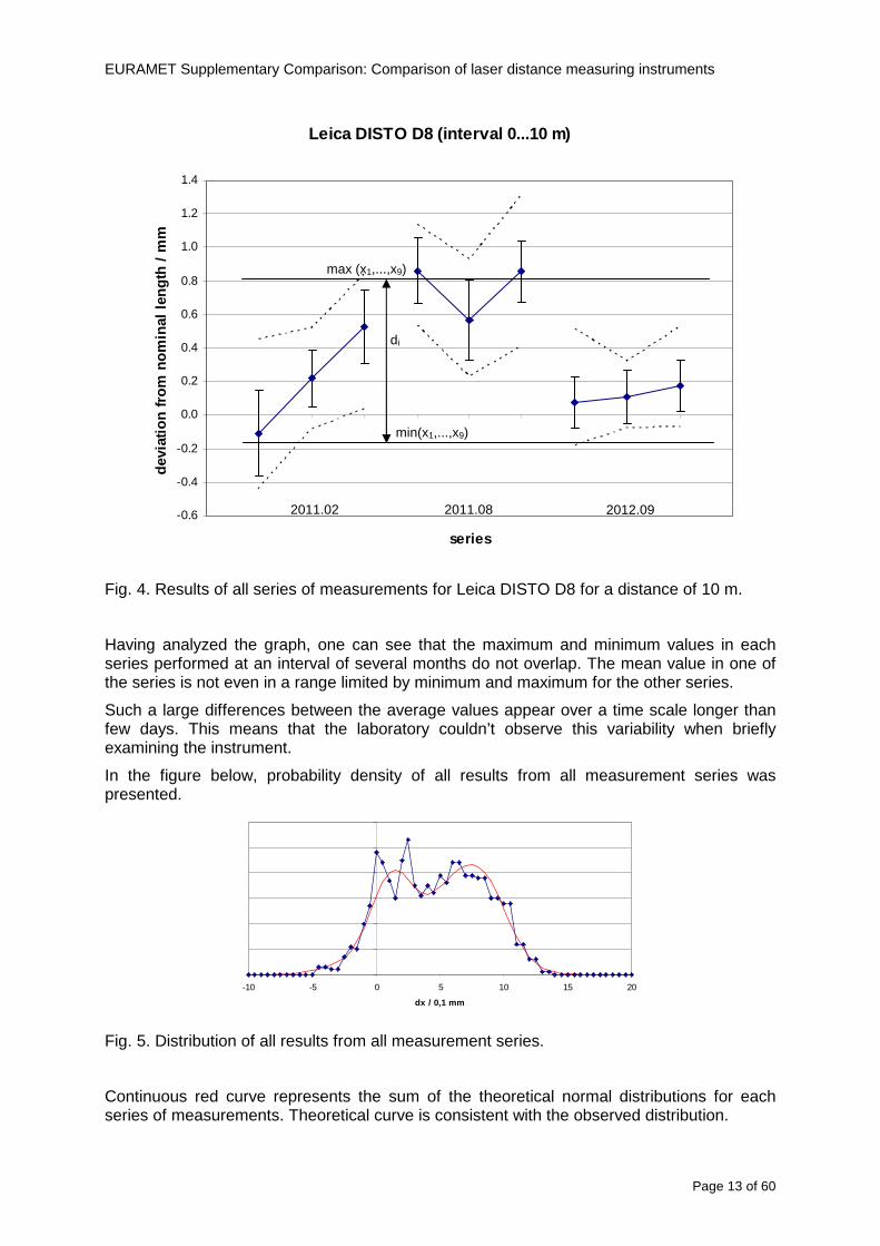
EURAMET Supplementary Comparison Comparison of laser distance measuring instruments
Page 15 of 60
Table 6 Values of u(dart) for all the four EDMs
EDM u(dart) (mm)
Bosch DLE 50 0308
Bosch GLM 150 0197
Leica DISTO D3a BT 0149
Leica DISTO D8 0324
Additional stability test of EDMs
The suspected main factors responsible for the change of EDMs indications are 1) Effects of electronics ndash resulting from unstable operation of the EDM 2) Effects of mechanics ndash impact of transport of the EDM between laboratories 3) Effects of geometry ndash alignment repeatability of the EDM during measurements
Two additional experiments were conducted in order to determine which factors have the greatest impact on the results Leica DISTO D3a BT was used for these tests
a) Static test
During the measurements the EDM was immobilized on a bench Measurements were made at a distance of 10 m in a controlled environment The measurement results are presented in the figure below
-04
-03
-02
-01
00
01
02
03
04
1 2 3 4 5 6 7 8 9 10 11 12 13 14 15 16 17 18 19 20
measure
dx
mm
Fig 7 Static stability test results
Each point represents the mean value of 15-20 measurements This test covers about 6 hours of EDM work The standard deviation is s = 009 mm
b) Dynamic test
Measurements were made at a distance of 10 m in a controlled environment After each series of measurements the EDM was removed from the bench shaken and squeezed The aim was to simulate the conditions during transportation This test covers about 6 hours of EDM work Measurement results are presented in the figure below
EURAMET Supplementary Comparison Comparison of laser distance measuring instruments
Page 16 of 60
-04
-03
-02
-01
00
01
02
03
04
1 2 3 4 5 6 7 8 9
measure
dx
mm
Fig 8 Dynamic stability test results
The standard deviation for this test is s = 015 mm and is greater than in the static test
The average standard deviation of three measurement series was estimated using the data from the comparison The value s = 009 mm is similar to the result in the static test
The estimated uncertainty associated with the artifact for this EDM is uart = 015 mm (see table above) The same value u = 015 mm was estimated from the stability test in the scale of tens of minutes Both values are close to the value of standard deviation for the dynamic test
These results may lead to the conclusion that the level of the effects of electronics mechanics and geometry have a similar impact on the long-term stability Due to this fact it is difficult to identify which of these factors has the greatest impact on the observed measurement results
EURAMET Supplementary Comparison Comparison of laser distance measuring instruments
Page 17 of 60
9 Reference values The standard approach is to use weighted mean for determining the reference value xref [12] This is calculated by the mean of all measurement values xi weighted by the inverse square of the standard uncertainties u(xi) associated with the measurements and using these values the largest consistent subset of the sample is determined However checking the consistency of the sample without taking into account the uncertainty associated with the artifact leads to erroneous recognition of the consistent subset We propose to add uart to the uncertainty of each laboratory at the beginning of the calculation
( ) )()( 222iartic xuduxu +=
Thereby the uncertainty associated with the artifact will be taken into account during the consistency check
sum
sum
=
==n
i ic
n
i ic
i
ref
xu
xu
x
x
12
12
)(
1
)(
The pilot laboratory contributed only by its first measurements to the reference values The weighted mean approach requires the individual uncertainties from the laboratories to be estimated according to a common approach (as they should be since all participants were requested to estimate the uncertainties according to the ISO Guide) The standard uncertainty u(xref) of the reference value is calculated by combining the individual uncertainties
sum=
=n
i ic
ref
xu
xu
12
2
)(
1
1)(
The χ2 test was applied in order to estimate xref from the largest consistent subset [1]
EURAMET Supplementary Comparison Comparison of laser distance measuring instruments
Page 18 of 60
Table 7 Reference values and associated standard uncertainties based on weighted mean
Distance Bosch DLE 50 Bosch GLM 150 Leica DISTO D3a BT
Leica DISTO D8
mm xref u(xref) xref u(xref) xref u(xref) xref u(xref)
300 299694 0138 300475 0084 300353 0071 300177 0113
5000 4999900 0139 4999774 0090 5000020 0074 4999659 0111
10000 10000041 0146 9999776 0096 10000285 0077 10000336 0114
15000 14999945 0154 14999781 0120 15000176 0080 15000258 0117
20000 19999804 0175 19999423 0124 20000112 0086 20000581 0118
25000 24999955 0186 24999526 0128 25000321 0094 25000754 0124
30000 29999586 0193 29999956 0138 30000140 0103 30000675 0129
35000 34999779 0235 35000051 0156 35000022 0119 35000844 0153
40000 40000185 0279 40000250 0159 40000476 0132 40001167 0151
45000 44999576 0315 45000208 0165 45000391 0155 45000974 0156
50000 49999983 0324 50000344 0169 50000319 0156 50001137 0157
EURAMET Supplementary Comparison Comparison of laser distance measuring instruments
Page 19 of 60
10 Deviations from reference values The following figures show results from NMIs for all of the distances Reference value is represented by a bold black line
Bosch DLE 50
-30
-25
-20
-15
-10
-05
00
05
10
15
20
25
30
0 5 10 15 20 25 30 35 40 45 50 55
Length m
Dev
iatio
n fr
om n
omin
al le
ngth
m
m
MIKES
SP
Metrosert
PTB
CMI
SMU
INM
INRIM
CEM
BEV
JV
METAS
GUM
Ref
Bosch GLM 150
-20
-15
-10
-05
00
05
10
15
20
0 5 10 15 20 25 30 35 40 45 50 55
Length m
Dev
iatio
n fr
om n
omin
al le
ngth
m
m
MIKES
SP
Metrosert
PTB
CMI
SMU
INM
INRIM
CEM
BEV
JV
METAS
GUM
Ref
Fig 9 Deviations from reference values
EURAMET Supplementary Comparison Comparison of laser distance measuring instruments
Page 20 of 60
Leica DISTO D3a BT
-20
-15
-10
-05
00
05
10
15
20
0 5 10 15 20 25 30 35 40 45 50 55
Length m
Dev
iatio
n fr
om n
omin
al le
ngth
m
m
MIKES
SP
Metrosert
PTB
CMI
SMU
INM
INRIM
CEM
BEV
JV
METAS
GUM
Ref
Leica DISTO D8
-20
-15
-10
-05
00
05
10
15
20
0 5 10 15 20 25 30 35 40 45 50 55
Length m
Dev
iatio
n fr
om n
omin
al le
ngth
m
m
MIKES
SP
Metrosert
PTB
CMI
SMU
INM
INRIM
CEM
BEV
JV
METAS
GUM
Ref
Fig 9 Deviations from reference values (continued)
The deviations Di from reference value xref are calculated by
refxxD ii minus=
For calculating the expanded uncertainty of these deviations U(Di) the corresponding uncertainties u(xi) and u(xref) cannot simply be geometrically added because the values xi and xref are correlated Due to the random changes described in section 6 uncertainty u(dart) was added [2] It can be shown that the expanded uncertainty U(Di) is given by
)()()(961)( art2
ref22 duxuxuDU ii +minus=
when xi belongs to the largest consistent subset and
)()()(961)( art2
ref22 duxuxuDU ii ++=
EURAMET Supplementary Comparison Comparison of laser distance measuring instruments
Page 21 of 60
otherwise The deviations from the reference values are given in various figures and tables below The uncertainty bars in the figures correspond to the expanded uncertainties U(Di) (k = 196)
Fig 10 Deviations from reference values
EURAMET Supplementary Comparison Comparison of laser distance measuring instruments
Page 22 of 60
Fig 10 Deviations from reference values (continued)
EURAMET Supplementary Comparison Comparison of laser distance measuring instruments
Page 23 of 60
Fig 10 Deviations from reference values (continued)
EURAMET Supplementary Comparison Comparison of laser distance measuring instruments
Page 24 of 60
Fig 10 Deviations from reference values (continued)
EURAMET Supplementary Comparison Comparison of laser distance measuring instruments
Page 25 of 60
Fig 10 Deviations from reference values (continued)
EURAMET Supplementary Comparison Comparison of laser distance measuring instruments
Page 26 of 60
Fig 10 Deviations from reference values (continued)
EURAMET Supplementary Comparison Comparison of laser distance measuring instruments
Page 27 of 60
Fig 10 Deviations from reference values (continued)
EURAMET Supplementary Comparison Comparison of laser distance measuring instruments
Page 28 of 60
Fig 10 Deviations from reference values (continued)
EU
RA
ME
T S
upplementary C
omparison C
omparison of laser distance m
easuring instruments
P
age 29 of 60
Table 8 Deviations from the reference value (given at the top of the table) and expanded uncertainties (k=196) of such deviations for BOSCH DLE 50
Table 9 Deviations from the reference value (given at the top of the table) and expanded uncertainties (k=196) of such deviations for BOSCH GLM 150
EU
RA
ME
T S
upplementary C
omparison C
omparison of laser distance m
easuring instruments
P
age 30 of 60
Table 10 Deviations from the reference value (given at the top of the table) and expanded uncertainties (k=196) of such deviations for Leica DISTO D3a BT
Table 11 Deviations from the reference value (given at the top of the table) and expanded uncertainties (k=196) of such deviations for Leica DISTO D8
EURAMET Supplementary Comparison Comparison of laser distance measuring instruments
Page 31 of 60
11 En Tables Results with En gt 1 are marked with red color in Tables below En values are calculated by Di U(Di) with Di and U(Di) as given on page 19
Table 12 BOSCH DLE50
Lab Distance (mm) 300 5000 10000 15000 20000 25000 30000 35000 40000 45000 50000
MIKES -058 017 -019 -023 035 -002 -096 SP 020 019 006 005 009 059 064 037 028 097 001
Metrosert -030 -031 -003 018 032 PTB 001 029 022 -006 011 -036 001 -023 -075 -083 001 GUM -033 -005 -018 -009 000 006 017 005 -026 -028 019 CMI -003 020 -009 004 005 -022 028 SMU 006 -049 -034 -023 -017 -057 051 039 021 INM 032 031 037 006 020 005 -079 -119 -272 -260 -269
INRIM 025 -013 000 096 CEM -032 -022 -041 -039 -004 -038 080 001 -094 -047 BEV -010 007 000 -001 008 -011 037 013 -001 008 -001 JV -019 -016 025 -055 055 060 068 163 122 060 089
METAS 038 012 -005 007 -107 004 -024 002 -070 037 -052
Table 13 BOSCH GLM150
Lab Distance (mm) 300 5000 10000 15000 20000 25000 30000 35000 40000 45000 50000
MIKES 005 -002 019 018 027 019 062 SP 003 068 029 023 051 008 015 016 -005 -001 038
Metrosert -061 -011 -022 -021 -003 PTB 066 074 062 062 034 053 047 048 047 091 064 GUM -007 -014 007 -018 000 023 020 033 014 032 038 CMI -057 -032 -030 -064 -050 -047 000 SMU 023 -024 -060 012 062 001 -003 050 047 INM -022 017 -003 002 -003 054 005 -006 016 -022 -055
INRIM 079 -052 -050 -026 -034 -042 CEM 002 002 -034 -020 -029 -077 -077 -077 -074 -104 BEV -004 -002 -007 010 -042 -042 -029 -011 -028 -022 -030 JV 003 015 040 011 -020 021 -029 -005 028 036 058
METAS -047 -020 005 002 -012 -033 -054 -065 -053 -082 -040
Table 14 Leica DISTO D3a BT
Lab Distance (mm) 300 5000 10000 15000 20000 25000 30000 35000 40000 45000 50000
MIKES 008 094 050 -011 028 051 045 SP 033 038 056 017 053 065 076 051 017 071 011
Metrosert -060 -004 -037 -014 -002 PTB 067 000 070 030 089 062 061 081 124 050 072 GUM 023 019 035 008 038 053 029 058 070 064 063 CMI -001 -004 027 -011 011 034 -033 SMU 002 -013 -019 007 -013 -055 045 -013 -042 INM 002 -039 -058 001 002 -045 -080 -051 -102 -101 -378
INRIM 070 -020 063 101 CEM -028 -004 -004 -064 003 -002 -050 -022 -093 -160 BEV -032 -019 -019 004 -011 -037 -017 -002 -025 005 012 JV 027 019 027 042 046 039 043 048 072 115 024
METAS -091 -008 -102 -098 -111 -103 -092 -080 -073 -108 -043
EURAMET Supplementary Comparison Comparison of laser distance measuring instruments
Page 32 of 60
Table 15 Leica DISTO D8
Lab Distance (mm) 300 5000 10000 15000 20000 25000 30000 35000 40000 45000 50000
MIKES 025 013 058 036 038 061 022 SP 057 026 040 016 013 016 025 017 -007 -019 007
Metrosert -021 006 -016 -043 -019 PTB 040 011 035 -005 -011 -002 -004 035 047 022 069 GUM -028 005 -025 031 039 -015 029 048 041 052 072 CMI -104 -026 -072 -057 -006 -017 -015 SMU -067 -017 -051 -026 -016 -054 -004 -001 -016 INM 021 -014 009 003 -017 -031 -010 007 029 036 041
INRIM 076 -024 -004 047 -007 083 CEM 004 -009 002 -033 -051 -059 -097 -077 -116 -134 BEV -057 -014 -051 -093 -024 -027 -021 -036 -038 -028 -041 JV 014 031 047 030 044 043 035 056 093 108 030
METAS 035 007 026 038 -013 -024 -011 -048 -089 -074 -066
12 Conclusions It was the first comparison of EDMs For most of the laboratories it was an important opportunity to validate their measurement instrumentation and procedure It allowed to become aware of potential problems and to take corrective actions in changing the procedure
For the evaluation of the reference value the weighted mean approach has been chosen although the consistency check according to procedure A of Ref [1] failed in many cases A more complicated procedure for the evaluation of the reference value was proposed which slightly changes the uncertainty of the reference value
In total there were 23 En values larger than 1 This represents 47 of the full set of 482 results It is less than the 5 of possible values being out of the expanded uncertainty of the reference value for k=2
The uncertainty of the results mainly comes from the uncertainty of the reproducibility It is difficult to distinguish between Labrsquos calibration and measurement capability
The comparison shows a global compliance with declared CMCs independently of whether some participant can have a high percentage of values not compliant with its CMC due to the influence of the artifact and the estimation of its uncertainty
13 References [1] M G Cox The evaluation of key comparison data Metrologia 39 589 ndash 595 (2002)
[2] R Thalmann EUROMET 677 ndash Steel Tape Measures Final report (2004)
[3] F Pollinger personal communication
EURAMET Supplementary Comparison Comparison of laser distance measuring instruments
Page 33 of 60
Appendix 1 Description of the measurement equipmen t as reported by the laboratories
A11 MIKES Finland
Short description of measurement bench
MIKES interferometric bench is situated in an underground laboratory with air temperature and humidity control Typically air temperature is 20 plusmn 01 degC and humidity 45 plusmn 2 RH The linear guide on the top of the concrete beam comprises two parallel round shafts with adjustable fixtures every 1 m A carriage with ball bush bearings is moved along the rail and location of it is measured with reference interferometer HP-5529A Temperature of air is measured with 6 pt100 sensors and Keithley 2010 multimetre with 4-wire resistance mode Air pressure and humidity are measured with Vaisala PTU200 Updated Edleacuten equation by Boumlnsch amp Potulski is used for calculation of refractive index of air
For EDM calibration on the other end than laser interferometer is a fixed reference plate which is adjusted perpendicular to the laser beam Next to the reference plate is an adjustable base for EDM instrument with which it can be adjusted to point parallel and coincident with measurement arm of the interferometer A target plate adjusted perpendicular to laser beam is fixed to the carriage The calibration followed Abbe principle with some millimetre uncertainty in offset adjustment
First reference interferometer is set to zero when the target plate and reference plate are in contact then EDM is positioned and adjusted in its base The rear surface of the EDM is also slightly pressed against reference surface behind it Then the readings from both instruments are collected at selected locations For this calibration there is no fine adjustment of the target position so there are typically deviations of up to few millimetres from nominal locations Results are averages of 3-4 measurements
Additional remarks
The CMC entry MIKES has for EDM calibrations is based on calibration of length scales of high quality total stations and laser trackers This type of EDMs used in this comparison are not accurate enough for truly testing of MIKES calibration measurement capability
EURAMET Supplementary Comparison Comparison of laser distance measuring instruments
Page 34 of 60
A12 SP Sweden
Short description of measurement bench
The bench consists of a simple aluminium Uminusshaped profile with polished steel pins acting as supports for the tape The bench is a little over 50 m long and works as support for the reference tape and the calibrated EDMs simultaneously
Length measurement instrument
Comparison with reference steel tape
Temperature measurement system number and location of sensors
The tape temperature is continuously registered in 6 points equally distributed along the bench The air temperature is monitored during the measurements but not used for corrections
Additional remarks
The EDM support is placed approximately 2 cm vertically above the tape No visual aid is used
EURAMET Supplementary Comparison Comparison of laser distance measuring instruments
Page 35 of 60
A13 AS Metrosert Estonia
Short description of measurement bench
The 21-m bench is located in the designated corridor-like laboratory room The lab is air-conditioned and the stability of temperature is typically plusmn05 ordmC There are three humidity and temperature sensors in room for stability and gradient monitoring
Two stainless steel rails running in parallel are made of 3-m long rods The rails lay without fixed attachment on metal supports which are mounted on concrete base The base rests on pillars made of bricks
Length measurement instrument
Laser-interferometer system Renishaw ML10 was used as length measurement instrument
Laser interferometer gets temperature humidity and pressure data from itrsquos own measurement system EC10
Additional remarks
Due to the length of the bench only measurements up to 20 m could be made Five measurement series were made with each EDM
EURAMET Supplementary Comparison Comparison of laser distance measuring instruments
Page 36 of 60
A14 PTB Germany
Short description of measurement bench
The measurements were performed on the 50 m geodetic base of the PTB The comparator consists of a 50 m rail The laboratory is equipped with a network of 21 temperature sensors spaced by 25 m along the bench As depicted in fig 1 the EDM is mounted at one end of the comparator the reflector is fixed vertically on the carriage A large retroreflector is mounted approximately 150 mm below the EDM reflector on the carriage reflecting the beam of the reference interferometer The deviation of the length due to tilting carriage (Abbe error) has been investigated along the bench by comparison of two interferometers It remains smaller than 100 microm The distance of the first position of 300 mm with respect to the back side of the EDM is determined by a gauge block of 300 mm length and a thickness of 10 mm This procedure is depicted for one of the comparison standards in figure 2
For the calibration the desired positions are programmed After the carriage reaches a measurement position the operator waits for another 30 s for the carriage to settle In control experiments the remaining movement between positioning and measurement remained smaller than 2 microm The operator then activates the measurement of the EDM reads the indicated position and writes it down The procedure is repeated for twelve times at every position the mean of the 12 measurements represents the ldquoindicated distance by the EDMrdquo All measurements of a single run at one position are performed within approximately one minute The complete measurement was repeated for four times
Length measurement instrument
The reference length is determined by a frequency-calibrated laser interferometer (Agilent 5519A) The reference interferometer is set up in Michelson geometry the signals being digitalised by a Heidenhain IK 121 card The index of refraction is determined by the external weather station of the geodetic base consisting of 21 Pt-100 temperature sensors spaced 25 m along the bench two humidity sensors (Testo 650) and two pressure sensors (Setra 370 and DPI 141) The environmental parameters are used to determine the index of refraction for the reference measurement deploying the modification of the Edleacuten equation by Boumlnsch and Potulski
EURAMET Supplementary Comparison Comparison of laser distance measuring instruments
Page 37 of 60
A15 CMI Czech Republic
Description of measurement bench
The EDMs were measured on 30 m long measuring bench equipped by laser interferometer (LI) Renishaw ML10 (pic 1 and 2) calibrated traceable to national standard of length and quantities of environmental sensors The target plate and retroreflector of the LI were fixed on a moving part of the bench and each EDM was fixed in horizontal position by clamps (pic 3) LI and EDM are placed on opposite ends of bench the Abbe offset was lt10 mm for some of them and lt50mm for all The value of LI was reset (to zero) at position corresponding to the rear of the EDM (using 3D measuring arm FARO Quantum with uncertainty about 27microm) The perpendicularities of the EDM stop as well as target plate to the beam were also checked by FARO) Each EDM was 3x replaced and aligned the measurement (reading) was repeated 6 times for each alignment and position the mean value of these 3x6 measurements is stated in tables with results The uncertainty claimed covers the statistical uncertainty of single readings Only in case of Leica D8 (the best performing EDM in this comparison) we state also the uncertainty corresponding to the mean of 6 readings in last column (this uncertainty is smaller and better illustrates our CMC)
Length measurement instrument
- Laser interferometer Renishaw - Laser 633 nm Type ML10 - Compensator EC10 - 3D measuring arm FARO Quantum - 3D measuring arm FARO Quantum
EURAMET Supplementary Comparison Comparison of laser distance measuring instruments
Page 38 of 60
A16 SMU Slovakia
Short description of measurement bench
No bench is available at the SMU the measurements are being carried out in the underground corridor of the laboratory building with length of 428 m
The 50 m steel measuring tape KINEX was used as the reference laid on the floor and pulled by the force 50 N (the same force as had been applied during its calibration at the SMU) The calibration of reference tape was done at the SMU using ULM3m Zeiss with laser interferometer Agilent 5529 B (ie per 3 m parts)
Three mercury thermometers with the resolution of 01 degC were used along the measurement path each of them laid onto the tape and located at 667 m 1990 m (instead of 20 m because of this was one of measuring points) and 333 m respectively Each of them thus corresponded approximately to one third of the measured steel tape section
Regarding the 03 m measuring point the ULM3m Zeiss length measuring machine was used with the 300 mm gauge block as the reference
Length measurement instrument
We used our own target plate being fixed perpendicularly (within uncertainty stated) to the construction equipped with nonius and the camera holder transported manually along the steel tape The second construction was fixed to the tape by such a way that zero line of the tape corresponded to the rear of EDM (within uncertainty stated)
The position of the target is read on the monitor and 20 repeated readings of the EDM data took place in each measuring point (multiples of 5 m up to 40 m)
Concerning 03 m the 300 mm gauge block was fit between the target plate and the construction with EDM The distance of the EDM rear from the target plate corresponded to the length of gauge block (within uncertainty stated)
Additional remarks
The identical measurement method was used as we use to do within our calibration service although the results reporting is different ndash we provide the regression line calculated from the measurement of irregularly distributed points and corresponding uncertainty (k = 2) in the form of [a bL] mm (ie the same coefficients for each length in the range (0 ndash 42) m)
SMU hasnrsquot got this category in CMC tables
EURAMET Supplementary Comparison Comparison of laser distance measuring instruments
Page 39 of 60
A17 INM Romania
Short description of measurement bench
Geodesic base located in the basement of the laboratory with nominal length equal to 50 m having a mobile carriage thet support both laser He-Ne retroreflector and the target of the laser distance measuring instrument in the front of geodesic base exists a support where are aligned both laser interferometer and the laser distance measuring instruments
Length measurement instrument
Laser interferometer type Hewlett Packard model 5526 A with nominal length equal to 50 m resolution 0001 mm
U = 02 microm +0510-6L
Additional remarks
During the measurements the maximum gradient of temperature was equal to 05 degC
EURAMET Supplementary Comparison Comparison of laser distance measuring instruments
Page 40 of 60
A18 INRIM Italy
Short description of measurement bench
The facility for long distance measurements is located in a corridor of the gallery devoted to dimensional metrology The structure consists in a 28 m long rail fixed to a series of pillars which rest directly on the ground released from the vibrations of floor and wall The measuring system is based on a heterodyne interferometer whose mobile arm consists of a hollow retro-reflector mounted on a structure that can run along the rail so-called carriage A photograph of the facility is presented in Fig1
The carriage is moved by a micro-step motor the motor driver receives a digital pulse and converts it into an electrical pulse to run the motor Each pulse causes a rotation of the motor shaft of one step which amounts to 11000 of a complete revolution of the shaft If the pulse frequency increases the rotation becomes continuous with a speed that is directly proportional to the pulse frequency The speed ranges between few microms up to 27 ms with a resolution of 03 microms
Since the carriage must move back and forth automatically for a distance of almost 30 m a remote control to send pulses to the motor driver was implemented It consists of two parts a radio command which allows to set some general parameters of the carriage movement such as the movement direction and mode of travel (slow or fast) and a fast command which is performed by an amplitude modulated laser beam placed at the beginning of the track oriented towards the carriage A photo detector placed above the carriage receives the modulated laser beam which is transformed into pulses to be sent to the driver of the motor The modulation of the laser beam is implemented by a LabView program that controls a digital output of the data acquisition device
Length measurement instrument
The length measurement instrument is based on a heterodyne incremental interferometer The main beam of the interferometer with frequency f1 is generated by a frequency stabilized
EURAMET Supplementary Comparison Comparison of laser distance measuring instruments
Page 41 of 60
He-Ne laser calibrated with respect to the INRIM length standard and sent to the measurement arm the second beam is a portion of the first one diffracted by an acousto-optic modulator (AOM) with frequency f2 = f1 + 80 MHz The reference detector acquires the beat note signal at 80 MHz while the measurement detector acquires a signal at 80 MHz whose phase is varied due to the displacement of the retro-reflector moving on the rail In figure 2 the optical design of the interferometer is presented
Two different measuring techniques have been implemented
1 the ldquophase measuringrdquo technique based on fringes counting with a relative uncertainty of 5middot10-7 but limited at the maximum carriage speed of 3 cms
2 the ldquoDoppler frequency measurementrdquo technique for higher carriage speed based on the measurement of the Doppler frequency shift while the carriage runs
The second technique was validated by means of the comparison with the first technique at low speed with an agreement of the order of 3middot10-6 hence the Doppler frequency method could be considered validated within 01 mm over the whole rail path with the advantage of reducing the time needed to cover long distances so it was used for the EDM comparison
In order to obtain the distance covered by the carriage according to technique 2 the Doppler frequency is measured by a commercial high-performance counter (a Pendulum CNT-90) without dead time based on time stamping then it is converted in speed and integrated over time according to the following formula
( ) ( )int minus=minus= tffn
dtn
ffdairair
λλ
2
1
2
1
where d is the distance covered by the carriage f is the frequency of the measuring signal with the carriage at rest frsquo the frequency of the measuring signal with the carriage moving λi
is the wavelength of the laser in vacuum n - air is the air refractive index and ti is the integration time The difference frsquo-f is just the Doppler frequency due to the moving carriage
The time interval measurement resolution of the instrument is 100 ps and the time base is
EURAMET Supplementary Comparison Comparison of laser distance measuring instruments
Page 42 of 60
connected to the INRIM UTC so that the measurements of the Doppler frequency and the integration time are extremely accurate The environmental parameters such as air temperature atmospheric pressure partial pressure of water were monitored during the measurement process in order to calculate the value of air refractive index according to the Edlenrsquos formula
Comparison set-up
The different technical solutions adopted for the EDMs and for the target plate positioning are discussed in this paragraph and sketched in figure 3
Fig 3 picture of the EDM and target positioning area
Target plate positioning
In order to use the provided target plate an ad-hoc mounting was manufactured at INRIM it consists in a sort of picture frame made in aluminum which slightly clamps the target folded in half and gives it the necessary stiffness to be a reproducible target The upper part of the frame is L-shaped and allows it to be fixed to the carriage structure by means of two screws The rear part of the target mounting is depicted in figure 4 The target mounting was considered necessary because of the poor stiffness and planarity of the plastic target With the aluminium frame a planarity better than 01 mm was guaranteed The target plate is placed few centimetres next to the retro-reflector and normal to the interferometer beam axis since the EDM laser should be as close and parallel as possible to the reference beam
EURAMET Supplementary Comparison Comparison of laser distance measuring instruments
Page 43 of 60
Fig 4 picture of the rear part of the target plate mounting
EDMsrsquo positioning
The EDMs are placed on a cradle-like platform which is able to adjust the inclination of the EDM along the longitudinal axis (pitch angle) The platform height allows the EDMs to be at approx the same height as the interferometer beam A crucial role was played by the stop-wall placed behind the platform since it represents the ldquozero pointrdquo for all the length measurement Hence a particular effort was devoted to align the stop-wall so that it was normal to the interferometer beam axis and parallel to the target plate
Fig 5 detail of EDMsrsquo positioning the cradle-like platform and the stop-wall are well visible
EURAMET Supplementary Comparison Comparison of laser distance measuring instruments
Page 44 of 60
Target and stop-wall alignment
In order to have the stop-wall parallel to the target plate and normal to the interferometer beam axis the following procedure has been used
1) the stop-wall and the target plate were roughly placed trying to set them parallel and normal to the rail by eye (ie within few millimeters)
2) in order to check if the target was normal to the rail one EDM was positioned on the platform the pitch and yaw angles of the EDM were adjusted by observing the position of the EDM laser spot on the target plate when the target is moved along the rail fixed position means laser beam parallel to the carriage movement Then the target was moved until the end of the rail and a thin mirror was kept in contact with it hence observing the EDM laser reflected by the mirror it was possible to adjust the target tilt acting on the screws until the laser beam is reflected back to the source
3) finally in order to check the parallelism between the stop-wall and the target a tool made by a laser pointing orthogonally to its base was used the base was leant against the stop-wall and the laser was centered on the target when the target is near then the target was moved until the end of the rail hence observing the spot of the laser on the target it was possible to adjust the stop-wall orientation
The residual misalignment errors which we were not able to eliminate were kept into account in the uncertainty budget
Measurement of the first 30 cm
Due to the geometry of our set-up it was not possible to perform the first point of measurement by means of the interferometer indeed the carriage (hence the target) is not able to go in contact with the stop-wall
Fig 6 measurement of the first 30 cm the ruler touching the stop-wall and the target and the mechanical probe (in the back) touching the carriage are visible
EURAMET Supplementary Comparison Comparison of laser distance measuring instruments
Page 45 of 60
So a ruler made of aluminum with rounded ends and nominal length equal to 30 cm was adopted to set the distance between the target plate and the stop-wall for the first point of measurement as it is shown in figure 6 The ruler whose length was measured by a CMM machine was inserted between the target and the stop-wall leaning against the latter and the carriage was carefully moved towards the stop-wall until the target lightly touched the ruler A mechanical probe that touches the carriage structure when carriage is in the ldquo30 cmrdquo position was used as a reference measurement to check the repeatability of this distance after each measurement set
Fig 7 detail of the mechanical probe touching the carriage
Environmental parameters
The environmental parameters such as air temperature atmospheric pressure and humidity were monitored during the whole measurement process in order to calculate the value of air refractive index according to the Edlenrsquos formula
Among these parameters the temperature distribution along the mobile arm of the interferometer was our main concern mainly for two reasons
1 the temperature control of the gallery was not perfectly working during the measurement period so temperature drifts had to be monitored
2 longitudinal temperature gradients due to non uniform heating and to the presence of electronic instruments were pretty high
To the purpose 14 thermometers were uniformly dislocated along the rail and automatically recorded for all the measurement period Both temporal drifts and gradients along the path have been taken in account in the uncertainty budget In any case maximum temperature differences along the rail are within 1 degC In fig 8 an extract from the acquisition file is shown
Unfortunately the air conditioning system did not work well during the measurement campaign hence the measurements were performed at a mean temperature of 209 degC
EURAMET Supplementary Comparison Comparison of laser distance measuring instruments
Page 46 of 60
Fig 8 each curve represents the temperature distribution along the rail during the measurements campaign
Carriage waving
Since the rail is not perfectly straight and the measurement laser is not coincident with the measurement beam the Abbegrave error due to waving of the target must be considered A quantitative measurement and a qualitative measurement were carried out With an electronic level placed on the carriage the straightness on the vertical plane has been mapped with a half meter resolution (the data are reported in fig 9) With a laser placed on the carriage the horizontal and vertical waving are qualitatively compared by looking at the movements of the light spot on a target fixed to the rail end As a conclusion the horizontal and vertical waving are comparable in magnitude and the peak to peak error is of the order of 300 arcseconds
Fig 9 vertical waving of the target measured by an electronic level placed on the carriage
EURAMET Supplementary Comparison Comparison of laser distance measuring instruments
Page 47 of 60
Measurement procedure
The measurements were carried out according to the following procedure
The target was set in the starting position with the procedure described above
In sequence the four EDMs are positioned on the base the horizontal and vertical tilt are adjusted and the distance measurement is recorded An additional fifth EDM (Bosh DLE 150 property of INRiM) was included in the measurement sequence Each EDM is placed on the base and gently pushed against the reference wall in such a way that the measurement laser beam starting point is the same for all EDMs Than the horizontal and vertical angles were adjusted in order to hit the central point of the target indicated with two black marks (see pictures 3 and 6) with ldquovisualrdquo alignment The measurement button is then pressed several times (typically 5) and the average reading is recorded Typical dispersion between readings is within few last digit units In case the dispersion between readings is too large the anomaly is recorded
The carriage was then moved in the next position (about 5 m) and the measurement sequence was repeated for the 5 EDMs The operation is repeated up to 25 m The 25 m measurement is than repeated again as well as all the points till the first one so that each point is measured twice each set Since the carriage movement is ldquoopen looprdquo the positioning of the carriage was not exactly in the nominal 5 m intervals For each positioning the incremental displacement is measured by the interferometer in the Doppler mode Finally the measured values were averaged in order to give a single value for each nominal position
At the end of the measurement set when the carriage is at the 30 cm position again the sum of the interferometric measurements should be very close to zero The residual value is compared with the difference between the first and the final measurements of the mechanical probe The difference must be within the uncertainty of the Doppler technique otherwise some error occurred in the measurement set that must be repeated
At the end of the session 10 complete sets of measurements recorded from the 20th to the 30th of January 2012 have been considered for this report
Additional remarks
Effect of laser pointing
During a preliminary set of measurements we noticed a strong and unexpected dependence of the measurement result on the position of the laser spot on the target Indeed since no particular instructions were given about the relative position of the laser spot on target position (except to exclude the central joint between the two halves) we decided to work relatively close to the right side of the target -closer to the interferometer beam- in order to reduce the Abbegrave error We noticed very large errors at large distances in particular of the Leica DISTO D3a (see figure 10)
EURAMET Supplementary Comparison Comparison of laser distance measuring instruments
Page 48 of 60
Fig 10 errors of each EDM In a preliminary set of measurements
We also noticed that this error was strongly dependent on the position of the spot on the target For this reason we carried out a set of measurements at the maximum length in different positions of the target from one edge to the other according to figure 11 The results are reported in table V
EDM A B C D E
Leica D3a -4 +1 0 +24 +43
+2 0 +42 +40
-1 0 +38
Leica D8 0 0 0 2 +7
0 +12 +23
table V deviations (in mm) from the length measured at point C aiming the laser spot at different positions of the target (notations as in figure 11)
We tried to find an explanation to this effect in the shape of the laser spot if the spot was
EURAMET Supplementary Comparison Comparison of laser distance measuring instruments
Page 49 of 60
particularly defocused or had high diffraction some of the energy could fall out of the target and affect the measurement result In fact the images of the spots (shown in fig 12) do not support this hypothesis Finally we decided to use the center of the (half) target for the comparison
Changing the target
In order to investigate the influence of the target on the measurements a cardboard foil (400 x 400) mm was fixed to the target mounting and a complete set of measurements was performed The results reported in figure 13 and 14 do not show any evidence of a possible dependency of the EDM measurement on the target kind
EURAMET Supplementary Comparison Comparison of laser distance measuring instruments
Page 50 of 60
Measurement at 50 m
Although we are not able to perform traceable length measurements beyond 28 m we wanted to get a sense of EDMs behaviour at longer distances So a target (represented by a rack side wall) was placed at approximately 50 m one after the other the EDMrsquos were positioned on the base and pointed towards the target The measurements were repeated then the target was replaced by the target used for the comparison and a third set of measurements were performed To our great surprise all the EDMrsquos were in good agreement (within 2 or 3 mm for each set of measurement) even those which showed errors of the order of five to ten millimeters at 25 m namely BOSCH DLE 50 and LEICA DISTO D3a Therefore each set of measurements was averaged and the deviations from the mean value are reported in figure 15
EURAMET Supplementary Comparison Comparison of laser distance measuring instruments
Page 51 of 60
Fig 15 Deviations from average value of the measurements At 50 m
EURAMET Supplementary Comparison Comparison of laser distance measuring instruments
Page 52 of 60
A19 CEM Spain
Short description of the measurement bench
To make the measurements of EDMs we have used a reference line made of adjustable supports fixed on a wall of the laboratory Each support is nominally separated five metres from the previous one so we can generate reference lengths up to fifty metres with a pitch of five metres The supports are designed to accommodate both targets and handheld EDMs Distances between supports were measured by using a total station traced to national standards The relative angles of the bases have been measured and corrected
Fig 1 - View of three consecutive supports of the 50 m baseline (left) Lab technician situating an EDM on the first support of the baseline (right)
Length measurement instrument
The baseline was calibrated by using a total station Leica TDA5005 with spherical reflector the calibration uncertainty being 02 mm for k = 2
The target is provided by the comparison The quality of the target was judged as not good due to geometrical constructive errors and the lack of rigidity and stability We measured the flatness of the target surface the distance edge-surface and the angle between them by using a 3D coordinate measuring machine The results of flatness and angle were included in the uncertainty budget and the distance EDM-target was corrected for each EDM due to each beam impinged on a different point of the target
We were not able to measure the distance 0 to 03 m because the baseline pitch is 5 meters and although we are able to measure shorter values in a different facility the target was not appropriate for our bench
EURAMET Supplementary Comparison Comparison of laser distance measuring instruments
Page 53 of 60
Fig 2 - View of an EDM on the first support of the baseline (left) A closer look showing the support adjustments and the origin plate (right)
Fig 3 - View of the comparison target on one of the supports of the baseline (left) A closer look showing the target edge against the support rigid reference (right)
Measurement method
The measurements were carried out by comparison against the known values of the calibrated baseline (metallic references on supports)
Environmental conditions were maintained within the following limits
- Temperature 20 ordmC plusmn 05 ordmC
- Humidity 45 plusmn 10
Each laser distance measuring instrument was placed at the first support of the base and aligned so that the laser beam was perpendicular to the target as indicated by the comparison protocol
For each measurement we took the average of thirty measurements It permitted us to evaluate the repeatability of the instrument
EURAMET Supplementary Comparison Comparison of laser distance measuring instruments
Page 54 of 60
A110 BEV Austria
Short description of the measurement bench
Fig 1 Carriage of tape bench View from the laser interferometer side Retroreflector mounted on the vertical plate the EDM target is mounted on the backside
Fig 2 Support for the DUT Adjustable with 2 translational and 2 rotational degrees of freedom respectively
Fig 3 Setting of the 300 mm starting position Note the rough-and-ready mounted target plate
Fig 4 Laser interferometer side of the bench The DUT is 50 m away on the other side
EURAMET Supplementary Comparison Comparison of laser distance measuring instruments
Page 55 of 60
Measurement procedure 1 The EDM is positioned with the help of a 4-axis positioning stage so that its laser beam is
coaxial with the measurement direction of the laser interferometer (in head on configuration)
2 The EDM is removed from its support The bench carriage is positioned so that the distance of the target plate from the EDM back support is 300 mm A length bar with spherical faces is used for this adjustment The laser interferometer is preset to 300 mm and the EDM is put back on its support
3 At each position 10 consecutive measurements are taken (repeatability) and the carriage is moved to the next position The carriage is manually moved under control of the laser interferometer until it is within plusmn30 microm at the correct position (Exception for the DLE 150 the target is not positioned at 10 m but at 10 m ndash 1 mm to make use of the higher resolution) The indicated (not the nominal) distance of the laser interferometer is recorded for the determination of the deviation
4 After reaching the 50 m position all points are measured in reverse order (bidirectional) Immediately after the last measurement the EDM is removed and the indication using the 300 mm length bar is checked (thus noting a possible drift of the setup)
5 Each instrument was measured 4 times according to this procedure on different days (reproducibility of bench and instrument)
Length measurement instrument
Agilent laser interferometer with long range option The bench was completed short time before performing these measurement So the characterisation was not complete and the respective measurement uncertainty of the laser interferometer is estimated rather high But anyway its contribution to the overall uncertainty can nearly be neglected
Additional remarks
The uncertainty originating from the DUT is the dominating uncertainty contribution Specifically the resolution of the two Bosch instruments (1 mm) and the repeatability are the largest contributions For the DLA 50 the pooled standard deviation of a reading at 50 m is larger than 2 mm Moreover the length dependence is not a simple function
All of the instruments show a significant deviation of the laser beam from the normal of the back (reference) face of the instrument The measured angles reach from 04deg (D3a) to 11deg (DLE 50) This leads depending on the outer dimensions of the instruments to a constant uncertainty contribution of 02 mm in our setup It must be noted that the reference faces are not well defined in most of the instruments
The reproducibility is quite different for the four instruments so only part of it originates from the setup For CMC claims we will use the standard uncertainty value of the most reproducible instrument (D3a) which amounts to 013 mm For an ideal instrument with a resolution of 01 mm and perfect repeatability we would thus have a constant expanded uncertainty of 053 mm up to 50 m
EURAMET Supplementary Comparison Comparison of laser distance measuring instruments
Page 56 of 60
A111 JV Norway
Short description of measurement bench
EDM under calibration and the reference system are aligned along a 50 m measurement bench with rails to carry the linear movement of a target plate for the EDM and a corner cube reflector for the reference system The distance between parallel axis of EDM and axis of the reference system is 130 mm Abbe error due to angle errors for the movement is smaller than 01 mm and is corrected for at each measurement point At long lengths an aperture is used approximately midway between the target plate and the EDM to avoid interfering stray light to the EDM
Alignment procedure
1) Alignment of reference system to the movement of the carriage (rails)
2) Alignment of the EDM to the movement of the carriage (rails)
3) Alignment of a plane mirror at the position of the target plate using back-reflection to the EDM output (normal incident of light on the mirror)
4) Take out the EDM and align the zero reference plate at the back of the EDM to the plane mirror
5) The mirror is replaced by the target plate and the target plate is aligned to the zero reference plate
6) Zero setting of the reference measurement system when target plate is at zero distance to the reference plate at the back of the EDM
7) Put the EDM back in position and realign it to the movement of the carriage (rails)
8) Zero setting of the EDM to the reference plate
Image 1) Image 2) Image 3) Image 4)
Image 1) Items 5) ndash 6) in alignment procedure
Fixture for HP linear interferometer is seen bottom right Part of Wyler instrument is seen to the left blue colour
Image 2) Items 7) and 8) in alignment procedure
Micrometer screws for angle alignment in two directions and linear translation for zero setting of the EDM Push button on the EDM is positioned at the tilting point of the angle adjustment table to maximize stability during measurement HP 5519 A laser head is seen to the right
Image 3) Ready to measure at selected distances from zero point the reference plate
Image 4) EDM spot size at 50 m
Length measurement instrument
- Hewlett Packard Dynamic Calibrator 5519 A (max range 80 m)
- Pressure air temperature humidity Vaisala
EURAMET Supplementary Comparison Comparison of laser distance measuring instruments
Page 57 of 60
- Digital high resolution angle measurement Wyler
I used our own target plate which is of the same type as enclosed in the artefact suitcase article number 766560 from Leica but with reduced size width x hight = 90 x 137 mm
The zero reference plate is of similar type and size
Before measurements batteries of EDMs were switched to new batteries Old batteries are switched back after calibration
For L gt 5 m an aperture of similar size as the target plate is used approximately midway between the EDM and the target plate
Additional remarks
Reports on EDM indicated values at each measurement point is the average value of n = 5 repetitions A linear model of the standard deviation for the repeatability of the EDM readings at different lengths is estimated using m = 20 repetitions at least 5 positions along the scale An estimate of the length dependent repeatability is made for each instrument
The expanded uncertainty U(95) is rounded up to the limiting resolution of 1 mm in the interval 10 m to 40 m for Bosch GLM 150
After the calibration we also estimated the angle error of the optical axis of the EDM to its back plane (back reference of EDM) Bosch DLE 50 26 mrad up measured at 50 m Bosch GLM 150 8 mrad to the left measured at 50 m Leica DISTO D3a 37 mrad down measured at 20 m Leica DISTO D8 2 mrad to the left and 4 mrad down (45 mrad total) measured at 20 m
The distance between parallel walls will be measured too large if the back plane is assumed to be normal to the optical axis of the EDM by ∆LL = (1cosα ndash 1) Bosch DLE 50 ∆LL = 340 ppm (∆L = 17 mm at L = 50 m) Bosch GLM 150 ∆LL = 32 ppm (∆L = 16 mm at L = 50 m) Leica DISTO D3a ∆LL = 7 ppm (∆L = 034 mm at L = 50 m) Leica DISTO D8 ∆LL = 10 ppm (∆L = 05 mm at L = 50 m)
EURAMET Supplementary Comparison Comparison of laser distance measuring instruments
Page 58 of 60
A112 METAS Switzerland
Short description of measurement bench (photo recom mended)
50 m bench with laser interferometer (see photo detailed description in Michel Degoumois Un Long laboratoire de mesure OFMETinfo Vol5 No 2 1998)
Length measurement instrument
HP 5529 B laser interferometer range 80 m
EURAMET Supplementary Comparison Comparison of laser distance measuring instruments
Page 59 of 60
A113 GUM Poland
Short description of measurement bench
The 50 m bench is situated in the corridor laboratory located in the basement and has its own air conditioning system with air temperature 20 plusmn 1 degC and humidity 50 plusmn 10 RH The measuring carriage is carried microscope with CCD camera and the optics associated with the interferometer The carriage is driven using belt-transmission and electrical engine with remote ndash controlled variable speed drive
The EDM was placed on the fixed adjustable plate on the other end than laser interferometer The target plate of the EDM was placed on the measuring carriage For each EDM 3 series of measurement were done Before the each measurement EDM was repositioned and aligned again
Length measurement instrument
1 Laser interferometer HP 5529A with long-range option laser head HP 5519A
2 Ambient measurement system number and location of sensors - 20 air temperature sensors type YSI with KEITHLEY multimeter they are placed very
close to axis of the laser beam - air pressure and humidity are measured with Vaisala barometer and
thermohigrometer - CO2 content was measured with analyzer made by Intelli Charge type SPN 4462
EURAMET Supplementary Comparison Comparison of laser distance measuring instruments
Page 60 of 60
Appendix 2 Corrections of reports
131 CEM Spain
CEM reported two errors in their report
1) Bosch GLM 150 EDM error for 35 m should be -08 mm instead of the indicated 08 mm
2) Leica DISTO D8 EDM error for 35 m should be -019 mm instead of the indicated 019 mm
Proposed corrections have been included in Tables 2 and 4 of the Final Report
132 AS Metrosert Estonia
AS Metrosert reported mixed up of all results for Bosch DLE 50 and Bosch GLM 150 The results and uncertainties sent for DLE 50 was results for GLM 150 and vice versa
Proposed corrections have been included in Tables 1 and 2 of the Final Report
133 INRIM Italy
Among the data reported from INRIM some anomalies were found in the measurements of BOSCH DLE 50 and LEICA DISTO D3a at distances of 20 and 25 m
After preliminary discussion on Draft A it was understood that those anomalies could be explained as a sensitivity of said instruments to the laser light that once diffused by the target is reflected by surfaces parallel to the measurement axis and detected together with the wanted signal The superimposition of the two signals can cause a ldquopullingrdquo effect leading to an overestimation of the distance being the reflected path always longer than the direct one Indeed in the INRIMrsquos set-up the target was mounted pretty close to the flat rail used for the carriage movement being likely responsible for unwanted reflections that disturbed the measurements
Since the errors reported in INRIMrsquos measurements can be ascribed to a defect of BOSCH DLE 50 and LEICA DISTO D3a andor to a lack of description of the working conditions of said instruments INRIM asked to eliminate its measurement points at 20 and 25 m of said instruments from the comparison
Proposed corrections have been included in Tables 1 and 3 of the Final Report
134 JV Norway
Justervesenet has changed the procedure and introduced two apertures instead of only one aperture (iris) which was positioned at half distance between EDM and target The reason is that the reference beam also has an aperture and it is positioned right below the beam from the EDM (130 mm distance between axes) Some diffusively reflected stray light from the EDM target might enter the aperture for the reference beam reflect at the measurement table and reach the detector of the EDM In our calibration set-up we have only seen problems at L gt 30 m We will position the first aperture at ca 5 m from the EDM and then the second aperture at ca 25 m This combination of two apertures will effectively eliminate interference of stray light from the measurement table to the EDM detector for all lengths up to 50 m
Justervesenet also increases the uncertainty component regarding repeatability reproducibility so that the expanded uncertainty increases from 14 mm to 15 mm
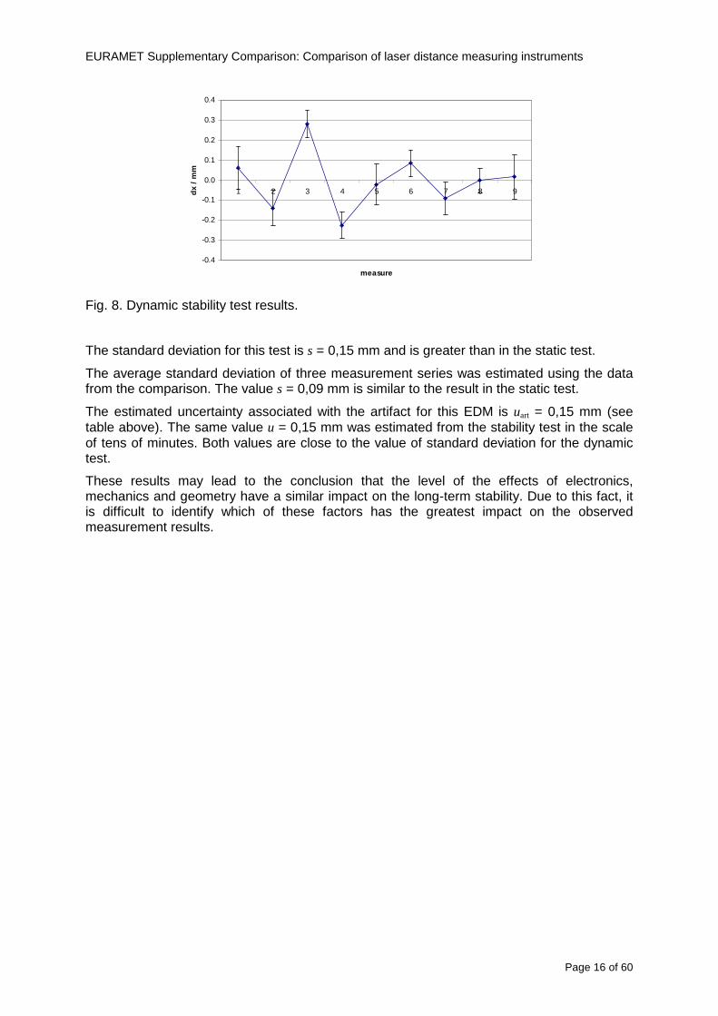
EURAMET Supplementary Comparison Comparison of laser distance measuring instruments
Page 16 of 60
-04
-03
-02
-01
00
01
02
03
04
1 2 3 4 5 6 7 8 9
measure
dx
mm
Fig 8 Dynamic stability test results
The standard deviation for this test is s = 015 mm and is greater than in the static test
The average standard deviation of three measurement series was estimated using the data from the comparison The value s = 009 mm is similar to the result in the static test
The estimated uncertainty associated with the artifact for this EDM is uart = 015 mm (see table above) The same value u = 015 mm was estimated from the stability test in the scale of tens of minutes Both values are close to the value of standard deviation for the dynamic test
These results may lead to the conclusion that the level of the effects of electronics mechanics and geometry have a similar impact on the long-term stability Due to this fact it is difficult to identify which of these factors has the greatest impact on the observed measurement results
EURAMET Supplementary Comparison Comparison of laser distance measuring instruments
Page 17 of 60
9 Reference values The standard approach is to use weighted mean for determining the reference value xref [12] This is calculated by the mean of all measurement values xi weighted by the inverse square of the standard uncertainties u(xi) associated with the measurements and using these values the largest consistent subset of the sample is determined However checking the consistency of the sample without taking into account the uncertainty associated with the artifact leads to erroneous recognition of the consistent subset We propose to add uart to the uncertainty of each laboratory at the beginning of the calculation
( ) )()( 222iartic xuduxu +=
Thereby the uncertainty associated with the artifact will be taken into account during the consistency check
sum
sum
=
==n
i ic
n
i ic
i
ref
xu
xu
x
x
12
12
)(
1
)(
The pilot laboratory contributed only by its first measurements to the reference values The weighted mean approach requires the individual uncertainties from the laboratories to be estimated according to a common approach (as they should be since all participants were requested to estimate the uncertainties according to the ISO Guide) The standard uncertainty u(xref) of the reference value is calculated by combining the individual uncertainties
sum=
=n
i ic
ref
xu
xu
12
2
)(
1
1)(
The χ2 test was applied in order to estimate xref from the largest consistent subset [1]
EURAMET Supplementary Comparison Comparison of laser distance measuring instruments
Page 18 of 60
Table 7 Reference values and associated standard uncertainties based on weighted mean
Distance Bosch DLE 50 Bosch GLM 150 Leica DISTO D3a BT
Leica DISTO D8
mm xref u(xref) xref u(xref) xref u(xref) xref u(xref)
300 299694 0138 300475 0084 300353 0071 300177 0113
5000 4999900 0139 4999774 0090 5000020 0074 4999659 0111
10000 10000041 0146 9999776 0096 10000285 0077 10000336 0114
15000 14999945 0154 14999781 0120 15000176 0080 15000258 0117
20000 19999804 0175 19999423 0124 20000112 0086 20000581 0118
25000 24999955 0186 24999526 0128 25000321 0094 25000754 0124
30000 29999586 0193 29999956 0138 30000140 0103 30000675 0129
35000 34999779 0235 35000051 0156 35000022 0119 35000844 0153
40000 40000185 0279 40000250 0159 40000476 0132 40001167 0151
45000 44999576 0315 45000208 0165 45000391 0155 45000974 0156
50000 49999983 0324 50000344 0169 50000319 0156 50001137 0157
EURAMET Supplementary Comparison Comparison of laser distance measuring instruments
Page 19 of 60
10 Deviations from reference values The following figures show results from NMIs for all of the distances Reference value is represented by a bold black line
Bosch DLE 50
-30
-25
-20
-15
-10
-05
00
05
10
15
20
25
30
0 5 10 15 20 25 30 35 40 45 50 55
Length m
Dev
iatio
n fr
om n
omin
al le
ngth
m
m
MIKES
SP
Metrosert
PTB
CMI
SMU
INM
INRIM
CEM
BEV
JV
METAS
GUM
Ref
Bosch GLM 150
-20
-15
-10
-05
00
05
10
15
20
0 5 10 15 20 25 30 35 40 45 50 55
Length m
Dev
iatio
n fr
om n
omin
al le
ngth
m
m
MIKES
SP
Metrosert
PTB
CMI
SMU
INM
INRIM
CEM
BEV
JV
METAS
GUM
Ref
Fig 9 Deviations from reference values
EURAMET Supplementary Comparison Comparison of laser distance measuring instruments
Page 20 of 60
Leica DISTO D3a BT
-20
-15
-10
-05
00
05
10
15
20
0 5 10 15 20 25 30 35 40 45 50 55
Length m
Dev
iatio
n fr
om n
omin
al le
ngth
m
m
MIKES
SP
Metrosert
PTB
CMI
SMU
INM
INRIM
CEM
BEV
JV
METAS
GUM
Ref
Leica DISTO D8
-20
-15
-10
-05
00
05
10
15
20
0 5 10 15 20 25 30 35 40 45 50 55
Length m
Dev
iatio
n fr
om n
omin
al le
ngth
m
m
MIKES
SP
Metrosert
PTB
CMI
SMU
INM
INRIM
CEM
BEV
JV
METAS
GUM
Ref
Fig 9 Deviations from reference values (continued)
The deviations Di from reference value xref are calculated by
refxxD ii minus=
For calculating the expanded uncertainty of these deviations U(Di) the corresponding uncertainties u(xi) and u(xref) cannot simply be geometrically added because the values xi and xref are correlated Due to the random changes described in section 6 uncertainty u(dart) was added [2] It can be shown that the expanded uncertainty U(Di) is given by
)()()(961)( art2
ref22 duxuxuDU ii +minus=
when xi belongs to the largest consistent subset and
)()()(961)( art2
ref22 duxuxuDU ii ++=
EURAMET Supplementary Comparison Comparison of laser distance measuring instruments
Page 21 of 60
otherwise The deviations from the reference values are given in various figures and tables below The uncertainty bars in the figures correspond to the expanded uncertainties U(Di) (k = 196)
Fig 10 Deviations from reference values
EURAMET Supplementary Comparison Comparison of laser distance measuring instruments
Page 22 of 60
Fig 10 Deviations from reference values (continued)
EURAMET Supplementary Comparison Comparison of laser distance measuring instruments
Page 23 of 60
Fig 10 Deviations from reference values (continued)
EURAMET Supplementary Comparison Comparison of laser distance measuring instruments
Page 24 of 60
Fig 10 Deviations from reference values (continued)
EURAMET Supplementary Comparison Comparison of laser distance measuring instruments
Page 25 of 60
Fig 10 Deviations from reference values (continued)
EURAMET Supplementary Comparison Comparison of laser distance measuring instruments
Page 26 of 60
Fig 10 Deviations from reference values (continued)
EURAMET Supplementary Comparison Comparison of laser distance measuring instruments
Page 27 of 60
Fig 10 Deviations from reference values (continued)
EURAMET Supplementary Comparison Comparison of laser distance measuring instruments
Page 28 of 60
Fig 10 Deviations from reference values (continued)
EU
RA
ME
T S
upplementary C
omparison C
omparison of laser distance m
easuring instruments
P
age 29 of 60
Table 8 Deviations from the reference value (given at the top of the table) and expanded uncertainties (k=196) of such deviations for BOSCH DLE 50
Table 9 Deviations from the reference value (given at the top of the table) and expanded uncertainties (k=196) of such deviations for BOSCH GLM 150
EU
RA
ME
T S
upplementary C
omparison C
omparison of laser distance m
easuring instruments
P
age 30 of 60
Table 10 Deviations from the reference value (given at the top of the table) and expanded uncertainties (k=196) of such deviations for Leica DISTO D3a BT
Table 11 Deviations from the reference value (given at the top of the table) and expanded uncertainties (k=196) of such deviations for Leica DISTO D8
EURAMET Supplementary Comparison Comparison of laser distance measuring instruments
Page 31 of 60
11 En Tables Results with En gt 1 are marked with red color in Tables below En values are calculated by Di U(Di) with Di and U(Di) as given on page 19
Table 12 BOSCH DLE50
Lab Distance (mm) 300 5000 10000 15000 20000 25000 30000 35000 40000 45000 50000
MIKES -058 017 -019 -023 035 -002 -096 SP 020 019 006 005 009 059 064 037 028 097 001
Metrosert -030 -031 -003 018 032 PTB 001 029 022 -006 011 -036 001 -023 -075 -083 001 GUM -033 -005 -018 -009 000 006 017 005 -026 -028 019 CMI -003 020 -009 004 005 -022 028 SMU 006 -049 -034 -023 -017 -057 051 039 021 INM 032 031 037 006 020 005 -079 -119 -272 -260 -269
INRIM 025 -013 000 096 CEM -032 -022 -041 -039 -004 -038 080 001 -094 -047 BEV -010 007 000 -001 008 -011 037 013 -001 008 -001 JV -019 -016 025 -055 055 060 068 163 122 060 089
METAS 038 012 -005 007 -107 004 -024 002 -070 037 -052
Table 13 BOSCH GLM150
Lab Distance (mm) 300 5000 10000 15000 20000 25000 30000 35000 40000 45000 50000
MIKES 005 -002 019 018 027 019 062 SP 003 068 029 023 051 008 015 016 -005 -001 038
Metrosert -061 -011 -022 -021 -003 PTB 066 074 062 062 034 053 047 048 047 091 064 GUM -007 -014 007 -018 000 023 020 033 014 032 038 CMI -057 -032 -030 -064 -050 -047 000 SMU 023 -024 -060 012 062 001 -003 050 047 INM -022 017 -003 002 -003 054 005 -006 016 -022 -055
INRIM 079 -052 -050 -026 -034 -042 CEM 002 002 -034 -020 -029 -077 -077 -077 -074 -104 BEV -004 -002 -007 010 -042 -042 -029 -011 -028 -022 -030 JV 003 015 040 011 -020 021 -029 -005 028 036 058
METAS -047 -020 005 002 -012 -033 -054 -065 -053 -082 -040
Table 14 Leica DISTO D3a BT
Lab Distance (mm) 300 5000 10000 15000 20000 25000 30000 35000 40000 45000 50000
MIKES 008 094 050 -011 028 051 045 SP 033 038 056 017 053 065 076 051 017 071 011
Metrosert -060 -004 -037 -014 -002 PTB 067 000 070 030 089 062 061 081 124 050 072 GUM 023 019 035 008 038 053 029 058 070 064 063 CMI -001 -004 027 -011 011 034 -033 SMU 002 -013 -019 007 -013 -055 045 -013 -042 INM 002 -039 -058 001 002 -045 -080 -051 -102 -101 -378
INRIM 070 -020 063 101 CEM -028 -004 -004 -064 003 -002 -050 -022 -093 -160 BEV -032 -019 -019 004 -011 -037 -017 -002 -025 005 012 JV 027 019 027 042 046 039 043 048 072 115 024
METAS -091 -008 -102 -098 -111 -103 -092 -080 -073 -108 -043
EURAMET Supplementary Comparison Comparison of laser distance measuring instruments
Page 32 of 60
Table 15 Leica DISTO D8
Lab Distance (mm) 300 5000 10000 15000 20000 25000 30000 35000 40000 45000 50000
MIKES 025 013 058 036 038 061 022 SP 057 026 040 016 013 016 025 017 -007 -019 007
Metrosert -021 006 -016 -043 -019 PTB 040 011 035 -005 -011 -002 -004 035 047 022 069 GUM -028 005 -025 031 039 -015 029 048 041 052 072 CMI -104 -026 -072 -057 -006 -017 -015 SMU -067 -017 -051 -026 -016 -054 -004 -001 -016 INM 021 -014 009 003 -017 -031 -010 007 029 036 041
INRIM 076 -024 -004 047 -007 083 CEM 004 -009 002 -033 -051 -059 -097 -077 -116 -134 BEV -057 -014 -051 -093 -024 -027 -021 -036 -038 -028 -041 JV 014 031 047 030 044 043 035 056 093 108 030
METAS 035 007 026 038 -013 -024 -011 -048 -089 -074 -066
12 Conclusions It was the first comparison of EDMs For most of the laboratories it was an important opportunity to validate their measurement instrumentation and procedure It allowed to become aware of potential problems and to take corrective actions in changing the procedure
For the evaluation of the reference value the weighted mean approach has been chosen although the consistency check according to procedure A of Ref [1] failed in many cases A more complicated procedure for the evaluation of the reference value was proposed which slightly changes the uncertainty of the reference value
In total there were 23 En values larger than 1 This represents 47 of the full set of 482 results It is less than the 5 of possible values being out of the expanded uncertainty of the reference value for k=2
The uncertainty of the results mainly comes from the uncertainty of the reproducibility It is difficult to distinguish between Labrsquos calibration and measurement capability
The comparison shows a global compliance with declared CMCs independently of whether some participant can have a high percentage of values not compliant with its CMC due to the influence of the artifact and the estimation of its uncertainty
13 References [1] M G Cox The evaluation of key comparison data Metrologia 39 589 ndash 595 (2002)
[2] R Thalmann EUROMET 677 ndash Steel Tape Measures Final report (2004)
[3] F Pollinger personal communication
EURAMET Supplementary Comparison Comparison of laser distance measuring instruments
Page 33 of 60
Appendix 1 Description of the measurement equipmen t as reported by the laboratories
A11 MIKES Finland
Short description of measurement bench
MIKES interferometric bench is situated in an underground laboratory with air temperature and humidity control Typically air temperature is 20 plusmn 01 degC and humidity 45 plusmn 2 RH The linear guide on the top of the concrete beam comprises two parallel round shafts with adjustable fixtures every 1 m A carriage with ball bush bearings is moved along the rail and location of it is measured with reference interferometer HP-5529A Temperature of air is measured with 6 pt100 sensors and Keithley 2010 multimetre with 4-wire resistance mode Air pressure and humidity are measured with Vaisala PTU200 Updated Edleacuten equation by Boumlnsch amp Potulski is used for calculation of refractive index of air
For EDM calibration on the other end than laser interferometer is a fixed reference plate which is adjusted perpendicular to the laser beam Next to the reference plate is an adjustable base for EDM instrument with which it can be adjusted to point parallel and coincident with measurement arm of the interferometer A target plate adjusted perpendicular to laser beam is fixed to the carriage The calibration followed Abbe principle with some millimetre uncertainty in offset adjustment
First reference interferometer is set to zero when the target plate and reference plate are in contact then EDM is positioned and adjusted in its base The rear surface of the EDM is also slightly pressed against reference surface behind it Then the readings from both instruments are collected at selected locations For this calibration there is no fine adjustment of the target position so there are typically deviations of up to few millimetres from nominal locations Results are averages of 3-4 measurements
Additional remarks
The CMC entry MIKES has for EDM calibrations is based on calibration of length scales of high quality total stations and laser trackers This type of EDMs used in this comparison are not accurate enough for truly testing of MIKES calibration measurement capability
EURAMET Supplementary Comparison Comparison of laser distance measuring instruments
Page 34 of 60
A12 SP Sweden
Short description of measurement bench
The bench consists of a simple aluminium Uminusshaped profile with polished steel pins acting as supports for the tape The bench is a little over 50 m long and works as support for the reference tape and the calibrated EDMs simultaneously
Length measurement instrument
Comparison with reference steel tape
Temperature measurement system number and location of sensors
The tape temperature is continuously registered in 6 points equally distributed along the bench The air temperature is monitored during the measurements but not used for corrections
Additional remarks
The EDM support is placed approximately 2 cm vertically above the tape No visual aid is used
EURAMET Supplementary Comparison Comparison of laser distance measuring instruments
Page 35 of 60
A13 AS Metrosert Estonia
Short description of measurement bench
The 21-m bench is located in the designated corridor-like laboratory room The lab is air-conditioned and the stability of temperature is typically plusmn05 ordmC There are three humidity and temperature sensors in room for stability and gradient monitoring
Two stainless steel rails running in parallel are made of 3-m long rods The rails lay without fixed attachment on metal supports which are mounted on concrete base The base rests on pillars made of bricks
Length measurement instrument
Laser-interferometer system Renishaw ML10 was used as length measurement instrument
Laser interferometer gets temperature humidity and pressure data from itrsquos own measurement system EC10
Additional remarks
Due to the length of the bench only measurements up to 20 m could be made Five measurement series were made with each EDM
EURAMET Supplementary Comparison Comparison of laser distance measuring instruments
Page 36 of 60
A14 PTB Germany
Short description of measurement bench
The measurements were performed on the 50 m geodetic base of the PTB The comparator consists of a 50 m rail The laboratory is equipped with a network of 21 temperature sensors spaced by 25 m along the bench As depicted in fig 1 the EDM is mounted at one end of the comparator the reflector is fixed vertically on the carriage A large retroreflector is mounted approximately 150 mm below the EDM reflector on the carriage reflecting the beam of the reference interferometer The deviation of the length due to tilting carriage (Abbe error) has been investigated along the bench by comparison of two interferometers It remains smaller than 100 microm The distance of the first position of 300 mm with respect to the back side of the EDM is determined by a gauge block of 300 mm length and a thickness of 10 mm This procedure is depicted for one of the comparison standards in figure 2
For the calibration the desired positions are programmed After the carriage reaches a measurement position the operator waits for another 30 s for the carriage to settle In control experiments the remaining movement between positioning and measurement remained smaller than 2 microm The operator then activates the measurement of the EDM reads the indicated position and writes it down The procedure is repeated for twelve times at every position the mean of the 12 measurements represents the ldquoindicated distance by the EDMrdquo All measurements of a single run at one position are performed within approximately one minute The complete measurement was repeated for four times
Length measurement instrument
The reference length is determined by a frequency-calibrated laser interferometer (Agilent 5519A) The reference interferometer is set up in Michelson geometry the signals being digitalised by a Heidenhain IK 121 card The index of refraction is determined by the external weather station of the geodetic base consisting of 21 Pt-100 temperature sensors spaced 25 m along the bench two humidity sensors (Testo 650) and two pressure sensors (Setra 370 and DPI 141) The environmental parameters are used to determine the index of refraction for the reference measurement deploying the modification of the Edleacuten equation by Boumlnsch and Potulski
EURAMET Supplementary Comparison Comparison of laser distance measuring instruments
Page 37 of 60
A15 CMI Czech Republic
Description of measurement bench
The EDMs were measured on 30 m long measuring bench equipped by laser interferometer (LI) Renishaw ML10 (pic 1 and 2) calibrated traceable to national standard of length and quantities of environmental sensors The target plate and retroreflector of the LI were fixed on a moving part of the bench and each EDM was fixed in horizontal position by clamps (pic 3) LI and EDM are placed on opposite ends of bench the Abbe offset was lt10 mm for some of them and lt50mm for all The value of LI was reset (to zero) at position corresponding to the rear of the EDM (using 3D measuring arm FARO Quantum with uncertainty about 27microm) The perpendicularities of the EDM stop as well as target plate to the beam were also checked by FARO) Each EDM was 3x replaced and aligned the measurement (reading) was repeated 6 times for each alignment and position the mean value of these 3x6 measurements is stated in tables with results The uncertainty claimed covers the statistical uncertainty of single readings Only in case of Leica D8 (the best performing EDM in this comparison) we state also the uncertainty corresponding to the mean of 6 readings in last column (this uncertainty is smaller and better illustrates our CMC)
Length measurement instrument
- Laser interferometer Renishaw - Laser 633 nm Type ML10 - Compensator EC10 - 3D measuring arm FARO Quantum - 3D measuring arm FARO Quantum
EURAMET Supplementary Comparison Comparison of laser distance measuring instruments
Page 38 of 60
A16 SMU Slovakia
Short description of measurement bench
No bench is available at the SMU the measurements are being carried out in the underground corridor of the laboratory building with length of 428 m
The 50 m steel measuring tape KINEX was used as the reference laid on the floor and pulled by the force 50 N (the same force as had been applied during its calibration at the SMU) The calibration of reference tape was done at the SMU using ULM3m Zeiss with laser interferometer Agilent 5529 B (ie per 3 m parts)
Three mercury thermometers with the resolution of 01 degC were used along the measurement path each of them laid onto the tape and located at 667 m 1990 m (instead of 20 m because of this was one of measuring points) and 333 m respectively Each of them thus corresponded approximately to one third of the measured steel tape section
Regarding the 03 m measuring point the ULM3m Zeiss length measuring machine was used with the 300 mm gauge block as the reference
Length measurement instrument
We used our own target plate being fixed perpendicularly (within uncertainty stated) to the construction equipped with nonius and the camera holder transported manually along the steel tape The second construction was fixed to the tape by such a way that zero line of the tape corresponded to the rear of EDM (within uncertainty stated)
The position of the target is read on the monitor and 20 repeated readings of the EDM data took place in each measuring point (multiples of 5 m up to 40 m)
Concerning 03 m the 300 mm gauge block was fit between the target plate and the construction with EDM The distance of the EDM rear from the target plate corresponded to the length of gauge block (within uncertainty stated)
Additional remarks
The identical measurement method was used as we use to do within our calibration service although the results reporting is different ndash we provide the regression line calculated from the measurement of irregularly distributed points and corresponding uncertainty (k = 2) in the form of [a bL] mm (ie the same coefficients for each length in the range (0 ndash 42) m)
SMU hasnrsquot got this category in CMC tables
EURAMET Supplementary Comparison Comparison of laser distance measuring instruments
Page 39 of 60
A17 INM Romania
Short description of measurement bench
Geodesic base located in the basement of the laboratory with nominal length equal to 50 m having a mobile carriage thet support both laser He-Ne retroreflector and the target of the laser distance measuring instrument in the front of geodesic base exists a support where are aligned both laser interferometer and the laser distance measuring instruments
Length measurement instrument
Laser interferometer type Hewlett Packard model 5526 A with nominal length equal to 50 m resolution 0001 mm
U = 02 microm +0510-6L
Additional remarks
During the measurements the maximum gradient of temperature was equal to 05 degC
EURAMET Supplementary Comparison Comparison of laser distance measuring instruments
Page 40 of 60
A18 INRIM Italy
Short description of measurement bench
The facility for long distance measurements is located in a corridor of the gallery devoted to dimensional metrology The structure consists in a 28 m long rail fixed to a series of pillars which rest directly on the ground released from the vibrations of floor and wall The measuring system is based on a heterodyne interferometer whose mobile arm consists of a hollow retro-reflector mounted on a structure that can run along the rail so-called carriage A photograph of the facility is presented in Fig1
The carriage is moved by a micro-step motor the motor driver receives a digital pulse and converts it into an electrical pulse to run the motor Each pulse causes a rotation of the motor shaft of one step which amounts to 11000 of a complete revolution of the shaft If the pulse frequency increases the rotation becomes continuous with a speed that is directly proportional to the pulse frequency The speed ranges between few microms up to 27 ms with a resolution of 03 microms
Since the carriage must move back and forth automatically for a distance of almost 30 m a remote control to send pulses to the motor driver was implemented It consists of two parts a radio command which allows to set some general parameters of the carriage movement such as the movement direction and mode of travel (slow or fast) and a fast command which is performed by an amplitude modulated laser beam placed at the beginning of the track oriented towards the carriage A photo detector placed above the carriage receives the modulated laser beam which is transformed into pulses to be sent to the driver of the motor The modulation of the laser beam is implemented by a LabView program that controls a digital output of the data acquisition device
Length measurement instrument
The length measurement instrument is based on a heterodyne incremental interferometer The main beam of the interferometer with frequency f1 is generated by a frequency stabilized
EURAMET Supplementary Comparison Comparison of laser distance measuring instruments
Page 41 of 60
He-Ne laser calibrated with respect to the INRIM length standard and sent to the measurement arm the second beam is a portion of the first one diffracted by an acousto-optic modulator (AOM) with frequency f2 = f1 + 80 MHz The reference detector acquires the beat note signal at 80 MHz while the measurement detector acquires a signal at 80 MHz whose phase is varied due to the displacement of the retro-reflector moving on the rail In figure 2 the optical design of the interferometer is presented
Two different measuring techniques have been implemented
1 the ldquophase measuringrdquo technique based on fringes counting with a relative uncertainty of 5middot10-7 but limited at the maximum carriage speed of 3 cms
2 the ldquoDoppler frequency measurementrdquo technique for higher carriage speed based on the measurement of the Doppler frequency shift while the carriage runs
The second technique was validated by means of the comparison with the first technique at low speed with an agreement of the order of 3middot10-6 hence the Doppler frequency method could be considered validated within 01 mm over the whole rail path with the advantage of reducing the time needed to cover long distances so it was used for the EDM comparison
In order to obtain the distance covered by the carriage according to technique 2 the Doppler frequency is measured by a commercial high-performance counter (a Pendulum CNT-90) without dead time based on time stamping then it is converted in speed and integrated over time according to the following formula
( ) ( )int minus=minus= tffn
dtn
ffdairair
λλ
2
1
2
1
where d is the distance covered by the carriage f is the frequency of the measuring signal with the carriage at rest frsquo the frequency of the measuring signal with the carriage moving λi
is the wavelength of the laser in vacuum n - air is the air refractive index and ti is the integration time The difference frsquo-f is just the Doppler frequency due to the moving carriage
The time interval measurement resolution of the instrument is 100 ps and the time base is
EURAMET Supplementary Comparison Comparison of laser distance measuring instruments
Page 42 of 60
connected to the INRIM UTC so that the measurements of the Doppler frequency and the integration time are extremely accurate The environmental parameters such as air temperature atmospheric pressure partial pressure of water were monitored during the measurement process in order to calculate the value of air refractive index according to the Edlenrsquos formula
Comparison set-up
The different technical solutions adopted for the EDMs and for the target plate positioning are discussed in this paragraph and sketched in figure 3
Fig 3 picture of the EDM and target positioning area
Target plate positioning
In order to use the provided target plate an ad-hoc mounting was manufactured at INRIM it consists in a sort of picture frame made in aluminum which slightly clamps the target folded in half and gives it the necessary stiffness to be a reproducible target The upper part of the frame is L-shaped and allows it to be fixed to the carriage structure by means of two screws The rear part of the target mounting is depicted in figure 4 The target mounting was considered necessary because of the poor stiffness and planarity of the plastic target With the aluminium frame a planarity better than 01 mm was guaranteed The target plate is placed few centimetres next to the retro-reflector and normal to the interferometer beam axis since the EDM laser should be as close and parallel as possible to the reference beam
EURAMET Supplementary Comparison Comparison of laser distance measuring instruments
Page 43 of 60
Fig 4 picture of the rear part of the target plate mounting
EDMsrsquo positioning
The EDMs are placed on a cradle-like platform which is able to adjust the inclination of the EDM along the longitudinal axis (pitch angle) The platform height allows the EDMs to be at approx the same height as the interferometer beam A crucial role was played by the stop-wall placed behind the platform since it represents the ldquozero pointrdquo for all the length measurement Hence a particular effort was devoted to align the stop-wall so that it was normal to the interferometer beam axis and parallel to the target plate
Fig 5 detail of EDMsrsquo positioning the cradle-like platform and the stop-wall are well visible
EURAMET Supplementary Comparison Comparison of laser distance measuring instruments
Page 44 of 60
Target and stop-wall alignment
In order to have the stop-wall parallel to the target plate and normal to the interferometer beam axis the following procedure has been used
1) the stop-wall and the target plate were roughly placed trying to set them parallel and normal to the rail by eye (ie within few millimeters)
2) in order to check if the target was normal to the rail one EDM was positioned on the platform the pitch and yaw angles of the EDM were adjusted by observing the position of the EDM laser spot on the target plate when the target is moved along the rail fixed position means laser beam parallel to the carriage movement Then the target was moved until the end of the rail and a thin mirror was kept in contact with it hence observing the EDM laser reflected by the mirror it was possible to adjust the target tilt acting on the screws until the laser beam is reflected back to the source
3) finally in order to check the parallelism between the stop-wall and the target a tool made by a laser pointing orthogonally to its base was used the base was leant against the stop-wall and the laser was centered on the target when the target is near then the target was moved until the end of the rail hence observing the spot of the laser on the target it was possible to adjust the stop-wall orientation
The residual misalignment errors which we were not able to eliminate were kept into account in the uncertainty budget
Measurement of the first 30 cm
Due to the geometry of our set-up it was not possible to perform the first point of measurement by means of the interferometer indeed the carriage (hence the target) is not able to go in contact with the stop-wall
Fig 6 measurement of the first 30 cm the ruler touching the stop-wall and the target and the mechanical probe (in the back) touching the carriage are visible
EURAMET Supplementary Comparison Comparison of laser distance measuring instruments
Page 45 of 60
So a ruler made of aluminum with rounded ends and nominal length equal to 30 cm was adopted to set the distance between the target plate and the stop-wall for the first point of measurement as it is shown in figure 6 The ruler whose length was measured by a CMM machine was inserted between the target and the stop-wall leaning against the latter and the carriage was carefully moved towards the stop-wall until the target lightly touched the ruler A mechanical probe that touches the carriage structure when carriage is in the ldquo30 cmrdquo position was used as a reference measurement to check the repeatability of this distance after each measurement set
Fig 7 detail of the mechanical probe touching the carriage
Environmental parameters
The environmental parameters such as air temperature atmospheric pressure and humidity were monitored during the whole measurement process in order to calculate the value of air refractive index according to the Edlenrsquos formula
Among these parameters the temperature distribution along the mobile arm of the interferometer was our main concern mainly for two reasons
1 the temperature control of the gallery was not perfectly working during the measurement period so temperature drifts had to be monitored
2 longitudinal temperature gradients due to non uniform heating and to the presence of electronic instruments were pretty high
To the purpose 14 thermometers were uniformly dislocated along the rail and automatically recorded for all the measurement period Both temporal drifts and gradients along the path have been taken in account in the uncertainty budget In any case maximum temperature differences along the rail are within 1 degC In fig 8 an extract from the acquisition file is shown
Unfortunately the air conditioning system did not work well during the measurement campaign hence the measurements were performed at a mean temperature of 209 degC
EURAMET Supplementary Comparison Comparison of laser distance measuring instruments
Page 46 of 60
Fig 8 each curve represents the temperature distribution along the rail during the measurements campaign
Carriage waving
Since the rail is not perfectly straight and the measurement laser is not coincident with the measurement beam the Abbegrave error due to waving of the target must be considered A quantitative measurement and a qualitative measurement were carried out With an electronic level placed on the carriage the straightness on the vertical plane has been mapped with a half meter resolution (the data are reported in fig 9) With a laser placed on the carriage the horizontal and vertical waving are qualitatively compared by looking at the movements of the light spot on a target fixed to the rail end As a conclusion the horizontal and vertical waving are comparable in magnitude and the peak to peak error is of the order of 300 arcseconds
Fig 9 vertical waving of the target measured by an electronic level placed on the carriage
EURAMET Supplementary Comparison Comparison of laser distance measuring instruments
Page 47 of 60
Measurement procedure
The measurements were carried out according to the following procedure
The target was set in the starting position with the procedure described above
In sequence the four EDMs are positioned on the base the horizontal and vertical tilt are adjusted and the distance measurement is recorded An additional fifth EDM (Bosh DLE 150 property of INRiM) was included in the measurement sequence Each EDM is placed on the base and gently pushed against the reference wall in such a way that the measurement laser beam starting point is the same for all EDMs Than the horizontal and vertical angles were adjusted in order to hit the central point of the target indicated with two black marks (see pictures 3 and 6) with ldquovisualrdquo alignment The measurement button is then pressed several times (typically 5) and the average reading is recorded Typical dispersion between readings is within few last digit units In case the dispersion between readings is too large the anomaly is recorded
The carriage was then moved in the next position (about 5 m) and the measurement sequence was repeated for the 5 EDMs The operation is repeated up to 25 m The 25 m measurement is than repeated again as well as all the points till the first one so that each point is measured twice each set Since the carriage movement is ldquoopen looprdquo the positioning of the carriage was not exactly in the nominal 5 m intervals For each positioning the incremental displacement is measured by the interferometer in the Doppler mode Finally the measured values were averaged in order to give a single value for each nominal position
At the end of the measurement set when the carriage is at the 30 cm position again the sum of the interferometric measurements should be very close to zero The residual value is compared with the difference between the first and the final measurements of the mechanical probe The difference must be within the uncertainty of the Doppler technique otherwise some error occurred in the measurement set that must be repeated
At the end of the session 10 complete sets of measurements recorded from the 20th to the 30th of January 2012 have been considered for this report
Additional remarks
Effect of laser pointing
During a preliminary set of measurements we noticed a strong and unexpected dependence of the measurement result on the position of the laser spot on the target Indeed since no particular instructions were given about the relative position of the laser spot on target position (except to exclude the central joint between the two halves) we decided to work relatively close to the right side of the target -closer to the interferometer beam- in order to reduce the Abbegrave error We noticed very large errors at large distances in particular of the Leica DISTO D3a (see figure 10)
EURAMET Supplementary Comparison Comparison of laser distance measuring instruments
Page 48 of 60
Fig 10 errors of each EDM In a preliminary set of measurements
We also noticed that this error was strongly dependent on the position of the spot on the target For this reason we carried out a set of measurements at the maximum length in different positions of the target from one edge to the other according to figure 11 The results are reported in table V
EDM A B C D E
Leica D3a -4 +1 0 +24 +43
+2 0 +42 +40
-1 0 +38
Leica D8 0 0 0 2 +7
0 +12 +23
table V deviations (in mm) from the length measured at point C aiming the laser spot at different positions of the target (notations as in figure 11)
We tried to find an explanation to this effect in the shape of the laser spot if the spot was
EURAMET Supplementary Comparison Comparison of laser distance measuring instruments
Page 49 of 60
particularly defocused or had high diffraction some of the energy could fall out of the target and affect the measurement result In fact the images of the spots (shown in fig 12) do not support this hypothesis Finally we decided to use the center of the (half) target for the comparison
Changing the target
In order to investigate the influence of the target on the measurements a cardboard foil (400 x 400) mm was fixed to the target mounting and a complete set of measurements was performed The results reported in figure 13 and 14 do not show any evidence of a possible dependency of the EDM measurement on the target kind
EURAMET Supplementary Comparison Comparison of laser distance measuring instruments
Page 50 of 60
Measurement at 50 m
Although we are not able to perform traceable length measurements beyond 28 m we wanted to get a sense of EDMs behaviour at longer distances So a target (represented by a rack side wall) was placed at approximately 50 m one after the other the EDMrsquos were positioned on the base and pointed towards the target The measurements were repeated then the target was replaced by the target used for the comparison and a third set of measurements were performed To our great surprise all the EDMrsquos were in good agreement (within 2 or 3 mm for each set of measurement) even those which showed errors of the order of five to ten millimeters at 25 m namely BOSCH DLE 50 and LEICA DISTO D3a Therefore each set of measurements was averaged and the deviations from the mean value are reported in figure 15
EURAMET Supplementary Comparison Comparison of laser distance measuring instruments
Page 51 of 60
Fig 15 Deviations from average value of the measurements At 50 m
EURAMET Supplementary Comparison Comparison of laser distance measuring instruments
Page 52 of 60
A19 CEM Spain
Short description of the measurement bench
To make the measurements of EDMs we have used a reference line made of adjustable supports fixed on a wall of the laboratory Each support is nominally separated five metres from the previous one so we can generate reference lengths up to fifty metres with a pitch of five metres The supports are designed to accommodate both targets and handheld EDMs Distances between supports were measured by using a total station traced to national standards The relative angles of the bases have been measured and corrected
Fig 1 - View of three consecutive supports of the 50 m baseline (left) Lab technician situating an EDM on the first support of the baseline (right)
Length measurement instrument
The baseline was calibrated by using a total station Leica TDA5005 with spherical reflector the calibration uncertainty being 02 mm for k = 2
The target is provided by the comparison The quality of the target was judged as not good due to geometrical constructive errors and the lack of rigidity and stability We measured the flatness of the target surface the distance edge-surface and the angle between them by using a 3D coordinate measuring machine The results of flatness and angle were included in the uncertainty budget and the distance EDM-target was corrected for each EDM due to each beam impinged on a different point of the target
We were not able to measure the distance 0 to 03 m because the baseline pitch is 5 meters and although we are able to measure shorter values in a different facility the target was not appropriate for our bench
EURAMET Supplementary Comparison Comparison of laser distance measuring instruments
Page 53 of 60
Fig 2 - View of an EDM on the first support of the baseline (left) A closer look showing the support adjustments and the origin plate (right)
Fig 3 - View of the comparison target on one of the supports of the baseline (left) A closer look showing the target edge against the support rigid reference (right)
Measurement method
The measurements were carried out by comparison against the known values of the calibrated baseline (metallic references on supports)
Environmental conditions were maintained within the following limits
- Temperature 20 ordmC plusmn 05 ordmC
- Humidity 45 plusmn 10
Each laser distance measuring instrument was placed at the first support of the base and aligned so that the laser beam was perpendicular to the target as indicated by the comparison protocol
For each measurement we took the average of thirty measurements It permitted us to evaluate the repeatability of the instrument
EURAMET Supplementary Comparison Comparison of laser distance measuring instruments
Page 54 of 60
A110 BEV Austria
Short description of the measurement bench
Fig 1 Carriage of tape bench View from the laser interferometer side Retroreflector mounted on the vertical plate the EDM target is mounted on the backside
Fig 2 Support for the DUT Adjustable with 2 translational and 2 rotational degrees of freedom respectively
Fig 3 Setting of the 300 mm starting position Note the rough-and-ready mounted target plate
Fig 4 Laser interferometer side of the bench The DUT is 50 m away on the other side
EURAMET Supplementary Comparison Comparison of laser distance measuring instruments
Page 55 of 60
Measurement procedure 1 The EDM is positioned with the help of a 4-axis positioning stage so that its laser beam is
coaxial with the measurement direction of the laser interferometer (in head on configuration)
2 The EDM is removed from its support The bench carriage is positioned so that the distance of the target plate from the EDM back support is 300 mm A length bar with spherical faces is used for this adjustment The laser interferometer is preset to 300 mm and the EDM is put back on its support
3 At each position 10 consecutive measurements are taken (repeatability) and the carriage is moved to the next position The carriage is manually moved under control of the laser interferometer until it is within plusmn30 microm at the correct position (Exception for the DLE 150 the target is not positioned at 10 m but at 10 m ndash 1 mm to make use of the higher resolution) The indicated (not the nominal) distance of the laser interferometer is recorded for the determination of the deviation
4 After reaching the 50 m position all points are measured in reverse order (bidirectional) Immediately after the last measurement the EDM is removed and the indication using the 300 mm length bar is checked (thus noting a possible drift of the setup)
5 Each instrument was measured 4 times according to this procedure on different days (reproducibility of bench and instrument)
Length measurement instrument
Agilent laser interferometer with long range option The bench was completed short time before performing these measurement So the characterisation was not complete and the respective measurement uncertainty of the laser interferometer is estimated rather high But anyway its contribution to the overall uncertainty can nearly be neglected
Additional remarks
The uncertainty originating from the DUT is the dominating uncertainty contribution Specifically the resolution of the two Bosch instruments (1 mm) and the repeatability are the largest contributions For the DLA 50 the pooled standard deviation of a reading at 50 m is larger than 2 mm Moreover the length dependence is not a simple function
All of the instruments show a significant deviation of the laser beam from the normal of the back (reference) face of the instrument The measured angles reach from 04deg (D3a) to 11deg (DLE 50) This leads depending on the outer dimensions of the instruments to a constant uncertainty contribution of 02 mm in our setup It must be noted that the reference faces are not well defined in most of the instruments
The reproducibility is quite different for the four instruments so only part of it originates from the setup For CMC claims we will use the standard uncertainty value of the most reproducible instrument (D3a) which amounts to 013 mm For an ideal instrument with a resolution of 01 mm and perfect repeatability we would thus have a constant expanded uncertainty of 053 mm up to 50 m
EURAMET Supplementary Comparison Comparison of laser distance measuring instruments
Page 56 of 60
A111 JV Norway
Short description of measurement bench
EDM under calibration and the reference system are aligned along a 50 m measurement bench with rails to carry the linear movement of a target plate for the EDM and a corner cube reflector for the reference system The distance between parallel axis of EDM and axis of the reference system is 130 mm Abbe error due to angle errors for the movement is smaller than 01 mm and is corrected for at each measurement point At long lengths an aperture is used approximately midway between the target plate and the EDM to avoid interfering stray light to the EDM
Alignment procedure
1) Alignment of reference system to the movement of the carriage (rails)
2) Alignment of the EDM to the movement of the carriage (rails)
3) Alignment of a plane mirror at the position of the target plate using back-reflection to the EDM output (normal incident of light on the mirror)
4) Take out the EDM and align the zero reference plate at the back of the EDM to the plane mirror
5) The mirror is replaced by the target plate and the target plate is aligned to the zero reference plate
6) Zero setting of the reference measurement system when target plate is at zero distance to the reference plate at the back of the EDM
7) Put the EDM back in position and realign it to the movement of the carriage (rails)
8) Zero setting of the EDM to the reference plate
Image 1) Image 2) Image 3) Image 4)
Image 1) Items 5) ndash 6) in alignment procedure
Fixture for HP linear interferometer is seen bottom right Part of Wyler instrument is seen to the left blue colour
Image 2) Items 7) and 8) in alignment procedure
Micrometer screws for angle alignment in two directions and linear translation for zero setting of the EDM Push button on the EDM is positioned at the tilting point of the angle adjustment table to maximize stability during measurement HP 5519 A laser head is seen to the right
Image 3) Ready to measure at selected distances from zero point the reference plate
Image 4) EDM spot size at 50 m
Length measurement instrument
- Hewlett Packard Dynamic Calibrator 5519 A (max range 80 m)
- Pressure air temperature humidity Vaisala
EURAMET Supplementary Comparison Comparison of laser distance measuring instruments
Page 57 of 60
- Digital high resolution angle measurement Wyler
I used our own target plate which is of the same type as enclosed in the artefact suitcase article number 766560 from Leica but with reduced size width x hight = 90 x 137 mm
The zero reference plate is of similar type and size
Before measurements batteries of EDMs were switched to new batteries Old batteries are switched back after calibration
For L gt 5 m an aperture of similar size as the target plate is used approximately midway between the EDM and the target plate
Additional remarks
Reports on EDM indicated values at each measurement point is the average value of n = 5 repetitions A linear model of the standard deviation for the repeatability of the EDM readings at different lengths is estimated using m = 20 repetitions at least 5 positions along the scale An estimate of the length dependent repeatability is made for each instrument
The expanded uncertainty U(95) is rounded up to the limiting resolution of 1 mm in the interval 10 m to 40 m for Bosch GLM 150
After the calibration we also estimated the angle error of the optical axis of the EDM to its back plane (back reference of EDM) Bosch DLE 50 26 mrad up measured at 50 m Bosch GLM 150 8 mrad to the left measured at 50 m Leica DISTO D3a 37 mrad down measured at 20 m Leica DISTO D8 2 mrad to the left and 4 mrad down (45 mrad total) measured at 20 m
The distance between parallel walls will be measured too large if the back plane is assumed to be normal to the optical axis of the EDM by ∆LL = (1cosα ndash 1) Bosch DLE 50 ∆LL = 340 ppm (∆L = 17 mm at L = 50 m) Bosch GLM 150 ∆LL = 32 ppm (∆L = 16 mm at L = 50 m) Leica DISTO D3a ∆LL = 7 ppm (∆L = 034 mm at L = 50 m) Leica DISTO D8 ∆LL = 10 ppm (∆L = 05 mm at L = 50 m)
EURAMET Supplementary Comparison Comparison of laser distance measuring instruments
Page 58 of 60
A112 METAS Switzerland
Short description of measurement bench (photo recom mended)
50 m bench with laser interferometer (see photo detailed description in Michel Degoumois Un Long laboratoire de mesure OFMETinfo Vol5 No 2 1998)
Length measurement instrument
HP 5529 B laser interferometer range 80 m
EURAMET Supplementary Comparison Comparison of laser distance measuring instruments
Page 59 of 60
A113 GUM Poland
Short description of measurement bench
The 50 m bench is situated in the corridor laboratory located in the basement and has its own air conditioning system with air temperature 20 plusmn 1 degC and humidity 50 plusmn 10 RH The measuring carriage is carried microscope with CCD camera and the optics associated with the interferometer The carriage is driven using belt-transmission and electrical engine with remote ndash controlled variable speed drive
The EDM was placed on the fixed adjustable plate on the other end than laser interferometer The target plate of the EDM was placed on the measuring carriage For each EDM 3 series of measurement were done Before the each measurement EDM was repositioned and aligned again
Length measurement instrument
1 Laser interferometer HP 5529A with long-range option laser head HP 5519A
2 Ambient measurement system number and location of sensors - 20 air temperature sensors type YSI with KEITHLEY multimeter they are placed very
close to axis of the laser beam - air pressure and humidity are measured with Vaisala barometer and
thermohigrometer - CO2 content was measured with analyzer made by Intelli Charge type SPN 4462
EURAMET Supplementary Comparison Comparison of laser distance measuring instruments
Page 60 of 60
Appendix 2 Corrections of reports
131 CEM Spain
CEM reported two errors in their report
1) Bosch GLM 150 EDM error for 35 m should be -08 mm instead of the indicated 08 mm
2) Leica DISTO D8 EDM error for 35 m should be -019 mm instead of the indicated 019 mm
Proposed corrections have been included in Tables 2 and 4 of the Final Report
132 AS Metrosert Estonia
AS Metrosert reported mixed up of all results for Bosch DLE 50 and Bosch GLM 150 The results and uncertainties sent for DLE 50 was results for GLM 150 and vice versa
Proposed corrections have been included in Tables 1 and 2 of the Final Report
133 INRIM Italy
Among the data reported from INRIM some anomalies were found in the measurements of BOSCH DLE 50 and LEICA DISTO D3a at distances of 20 and 25 m
After preliminary discussion on Draft A it was understood that those anomalies could be explained as a sensitivity of said instruments to the laser light that once diffused by the target is reflected by surfaces parallel to the measurement axis and detected together with the wanted signal The superimposition of the two signals can cause a ldquopullingrdquo effect leading to an overestimation of the distance being the reflected path always longer than the direct one Indeed in the INRIMrsquos set-up the target was mounted pretty close to the flat rail used for the carriage movement being likely responsible for unwanted reflections that disturbed the measurements
Since the errors reported in INRIMrsquos measurements can be ascribed to a defect of BOSCH DLE 50 and LEICA DISTO D3a andor to a lack of description of the working conditions of said instruments INRIM asked to eliminate its measurement points at 20 and 25 m of said instruments from the comparison
Proposed corrections have been included in Tables 1 and 3 of the Final Report
134 JV Norway
Justervesenet has changed the procedure and introduced two apertures instead of only one aperture (iris) which was positioned at half distance between EDM and target The reason is that the reference beam also has an aperture and it is positioned right below the beam from the EDM (130 mm distance between axes) Some diffusively reflected stray light from the EDM target might enter the aperture for the reference beam reflect at the measurement table and reach the detector of the EDM In our calibration set-up we have only seen problems at L gt 30 m We will position the first aperture at ca 5 m from the EDM and then the second aperture at ca 25 m This combination of two apertures will effectively eliminate interference of stray light from the measurement table to the EDM detector for all lengths up to 50 m
Justervesenet also increases the uncertainty component regarding repeatability reproducibility so that the expanded uncertainty increases from 14 mm to 15 mm
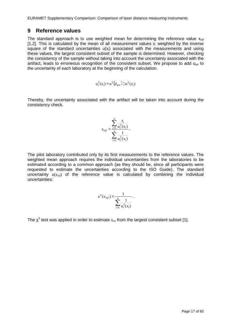
EURAMET Supplementary Comparison Comparison of laser distance measuring instruments
Page 17 of 60
9 Reference values The standard approach is to use weighted mean for determining the reference value xref [12] This is calculated by the mean of all measurement values xi weighted by the inverse square of the standard uncertainties u(xi) associated with the measurements and using these values the largest consistent subset of the sample is determined However checking the consistency of the sample without taking into account the uncertainty associated with the artifact leads to erroneous recognition of the consistent subset We propose to add uart to the uncertainty of each laboratory at the beginning of the calculation
( ) )()( 222iartic xuduxu +=
Thereby the uncertainty associated with the artifact will be taken into account during the consistency check
sum
sum
=
==n
i ic
n
i ic
i
ref
xu
xu
x
x
12
12
)(
1
)(
The pilot laboratory contributed only by its first measurements to the reference values The weighted mean approach requires the individual uncertainties from the laboratories to be estimated according to a common approach (as they should be since all participants were requested to estimate the uncertainties according to the ISO Guide) The standard uncertainty u(xref) of the reference value is calculated by combining the individual uncertainties
sum=
=n
i ic
ref
xu
xu
12
2
)(
1
1)(
The χ2 test was applied in order to estimate xref from the largest consistent subset [1]
EURAMET Supplementary Comparison Comparison of laser distance measuring instruments
Page 18 of 60
Table 7 Reference values and associated standard uncertainties based on weighted mean
Distance Bosch DLE 50 Bosch GLM 150 Leica DISTO D3a BT
Leica DISTO D8
mm xref u(xref) xref u(xref) xref u(xref) xref u(xref)
300 299694 0138 300475 0084 300353 0071 300177 0113
5000 4999900 0139 4999774 0090 5000020 0074 4999659 0111
10000 10000041 0146 9999776 0096 10000285 0077 10000336 0114
15000 14999945 0154 14999781 0120 15000176 0080 15000258 0117
20000 19999804 0175 19999423 0124 20000112 0086 20000581 0118
25000 24999955 0186 24999526 0128 25000321 0094 25000754 0124
30000 29999586 0193 29999956 0138 30000140 0103 30000675 0129
35000 34999779 0235 35000051 0156 35000022 0119 35000844 0153
40000 40000185 0279 40000250 0159 40000476 0132 40001167 0151
45000 44999576 0315 45000208 0165 45000391 0155 45000974 0156
50000 49999983 0324 50000344 0169 50000319 0156 50001137 0157
EURAMET Supplementary Comparison Comparison of laser distance measuring instruments
Page 19 of 60
10 Deviations from reference values The following figures show results from NMIs for all of the distances Reference value is represented by a bold black line
Bosch DLE 50
-30
-25
-20
-15
-10
-05
00
05
10
15
20
25
30
0 5 10 15 20 25 30 35 40 45 50 55
Length m
Dev
iatio
n fr
om n
omin
al le
ngth
m
m
MIKES
SP
Metrosert
PTB
CMI
SMU
INM
INRIM
CEM
BEV
JV
METAS
GUM
Ref
Bosch GLM 150
-20
-15
-10
-05
00
05
10
15
20
0 5 10 15 20 25 30 35 40 45 50 55
Length m
Dev
iatio
n fr
om n
omin
al le
ngth
m
m
MIKES
SP
Metrosert
PTB
CMI
SMU
INM
INRIM
CEM
BEV
JV
METAS
GUM
Ref
Fig 9 Deviations from reference values
EURAMET Supplementary Comparison Comparison of laser distance measuring instruments
Page 20 of 60
Leica DISTO D3a BT
-20
-15
-10
-05
00
05
10
15
20
0 5 10 15 20 25 30 35 40 45 50 55
Length m
Dev
iatio
n fr
om n
omin
al le
ngth
m
m
MIKES
SP
Metrosert
PTB
CMI
SMU
INM
INRIM
CEM
BEV
JV
METAS
GUM
Ref
Leica DISTO D8
-20
-15
-10
-05
00
05
10
15
20
0 5 10 15 20 25 30 35 40 45 50 55
Length m
Dev
iatio
n fr
om n
omin
al le
ngth
m
m
MIKES
SP
Metrosert
PTB
CMI
SMU
INM
INRIM
CEM
BEV
JV
METAS
GUM
Ref
Fig 9 Deviations from reference values (continued)
The deviations Di from reference value xref are calculated by
refxxD ii minus=
For calculating the expanded uncertainty of these deviations U(Di) the corresponding uncertainties u(xi) and u(xref) cannot simply be geometrically added because the values xi and xref are correlated Due to the random changes described in section 6 uncertainty u(dart) was added [2] It can be shown that the expanded uncertainty U(Di) is given by
)()()(961)( art2
ref22 duxuxuDU ii +minus=
when xi belongs to the largest consistent subset and
)()()(961)( art2
ref22 duxuxuDU ii ++=
EURAMET Supplementary Comparison Comparison of laser distance measuring instruments
Page 21 of 60
otherwise The deviations from the reference values are given in various figures and tables below The uncertainty bars in the figures correspond to the expanded uncertainties U(Di) (k = 196)
Fig 10 Deviations from reference values
EURAMET Supplementary Comparison Comparison of laser distance measuring instruments
Page 22 of 60
Fig 10 Deviations from reference values (continued)
EURAMET Supplementary Comparison Comparison of laser distance measuring instruments
Page 23 of 60
Fig 10 Deviations from reference values (continued)
EURAMET Supplementary Comparison Comparison of laser distance measuring instruments
Page 24 of 60
Fig 10 Deviations from reference values (continued)
EURAMET Supplementary Comparison Comparison of laser distance measuring instruments
Page 25 of 60
Fig 10 Deviations from reference values (continued)
EURAMET Supplementary Comparison Comparison of laser distance measuring instruments
Page 26 of 60
Fig 10 Deviations from reference values (continued)
EURAMET Supplementary Comparison Comparison of laser distance measuring instruments
Page 27 of 60
Fig 10 Deviations from reference values (continued)
EURAMET Supplementary Comparison Comparison of laser distance measuring instruments
Page 28 of 60
Fig 10 Deviations from reference values (continued)
EU
RA
ME
T S
upplementary C
omparison C
omparison of laser distance m
easuring instruments
P
age 29 of 60
Table 8 Deviations from the reference value (given at the top of the table) and expanded uncertainties (k=196) of such deviations for BOSCH DLE 50
Table 9 Deviations from the reference value (given at the top of the table) and expanded uncertainties (k=196) of such deviations for BOSCH GLM 150
EU
RA
ME
T S
upplementary C
omparison C
omparison of laser distance m
easuring instruments
P
age 30 of 60
Table 10 Deviations from the reference value (given at the top of the table) and expanded uncertainties (k=196) of such deviations for Leica DISTO D3a BT
Table 11 Deviations from the reference value (given at the top of the table) and expanded uncertainties (k=196) of such deviations for Leica DISTO D8
EURAMET Supplementary Comparison Comparison of laser distance measuring instruments
Page 31 of 60
11 En Tables Results with En gt 1 are marked with red color in Tables below En values are calculated by Di U(Di) with Di and U(Di) as given on page 19
Table 12 BOSCH DLE50
Lab Distance (mm) 300 5000 10000 15000 20000 25000 30000 35000 40000 45000 50000
MIKES -058 017 -019 -023 035 -002 -096 SP 020 019 006 005 009 059 064 037 028 097 001
Metrosert -030 -031 -003 018 032 PTB 001 029 022 -006 011 -036 001 -023 -075 -083 001 GUM -033 -005 -018 -009 000 006 017 005 -026 -028 019 CMI -003 020 -009 004 005 -022 028 SMU 006 -049 -034 -023 -017 -057 051 039 021 INM 032 031 037 006 020 005 -079 -119 -272 -260 -269
INRIM 025 -013 000 096 CEM -032 -022 -041 -039 -004 -038 080 001 -094 -047 BEV -010 007 000 -001 008 -011 037 013 -001 008 -001 JV -019 -016 025 -055 055 060 068 163 122 060 089
METAS 038 012 -005 007 -107 004 -024 002 -070 037 -052
Table 13 BOSCH GLM150
Lab Distance (mm) 300 5000 10000 15000 20000 25000 30000 35000 40000 45000 50000
MIKES 005 -002 019 018 027 019 062 SP 003 068 029 023 051 008 015 016 -005 -001 038
Metrosert -061 -011 -022 -021 -003 PTB 066 074 062 062 034 053 047 048 047 091 064 GUM -007 -014 007 -018 000 023 020 033 014 032 038 CMI -057 -032 -030 -064 -050 -047 000 SMU 023 -024 -060 012 062 001 -003 050 047 INM -022 017 -003 002 -003 054 005 -006 016 -022 -055
INRIM 079 -052 -050 -026 -034 -042 CEM 002 002 -034 -020 -029 -077 -077 -077 -074 -104 BEV -004 -002 -007 010 -042 -042 -029 -011 -028 -022 -030 JV 003 015 040 011 -020 021 -029 -005 028 036 058
METAS -047 -020 005 002 -012 -033 -054 -065 -053 -082 -040
Table 14 Leica DISTO D3a BT
Lab Distance (mm) 300 5000 10000 15000 20000 25000 30000 35000 40000 45000 50000
MIKES 008 094 050 -011 028 051 045 SP 033 038 056 017 053 065 076 051 017 071 011
Metrosert -060 -004 -037 -014 -002 PTB 067 000 070 030 089 062 061 081 124 050 072 GUM 023 019 035 008 038 053 029 058 070 064 063 CMI -001 -004 027 -011 011 034 -033 SMU 002 -013 -019 007 -013 -055 045 -013 -042 INM 002 -039 -058 001 002 -045 -080 -051 -102 -101 -378
INRIM 070 -020 063 101 CEM -028 -004 -004 -064 003 -002 -050 -022 -093 -160 BEV -032 -019 -019 004 -011 -037 -017 -002 -025 005 012 JV 027 019 027 042 046 039 043 048 072 115 024
METAS -091 -008 -102 -098 -111 -103 -092 -080 -073 -108 -043
EURAMET Supplementary Comparison Comparison of laser distance measuring instruments
Page 32 of 60
Table 15 Leica DISTO D8
Lab Distance (mm) 300 5000 10000 15000 20000 25000 30000 35000 40000 45000 50000
MIKES 025 013 058 036 038 061 022 SP 057 026 040 016 013 016 025 017 -007 -019 007
Metrosert -021 006 -016 -043 -019 PTB 040 011 035 -005 -011 -002 -004 035 047 022 069 GUM -028 005 -025 031 039 -015 029 048 041 052 072 CMI -104 -026 -072 -057 -006 -017 -015 SMU -067 -017 -051 -026 -016 -054 -004 -001 -016 INM 021 -014 009 003 -017 -031 -010 007 029 036 041
INRIM 076 -024 -004 047 -007 083 CEM 004 -009 002 -033 -051 -059 -097 -077 -116 -134 BEV -057 -014 -051 -093 -024 -027 -021 -036 -038 -028 -041 JV 014 031 047 030 044 043 035 056 093 108 030
METAS 035 007 026 038 -013 -024 -011 -048 -089 -074 -066
12 Conclusions It was the first comparison of EDMs For most of the laboratories it was an important opportunity to validate their measurement instrumentation and procedure It allowed to become aware of potential problems and to take corrective actions in changing the procedure
For the evaluation of the reference value the weighted mean approach has been chosen although the consistency check according to procedure A of Ref [1] failed in many cases A more complicated procedure for the evaluation of the reference value was proposed which slightly changes the uncertainty of the reference value
In total there were 23 En values larger than 1 This represents 47 of the full set of 482 results It is less than the 5 of possible values being out of the expanded uncertainty of the reference value for k=2
The uncertainty of the results mainly comes from the uncertainty of the reproducibility It is difficult to distinguish between Labrsquos calibration and measurement capability
The comparison shows a global compliance with declared CMCs independently of whether some participant can have a high percentage of values not compliant with its CMC due to the influence of the artifact and the estimation of its uncertainty
13 References [1] M G Cox The evaluation of key comparison data Metrologia 39 589 ndash 595 (2002)
[2] R Thalmann EUROMET 677 ndash Steel Tape Measures Final report (2004)
[3] F Pollinger personal communication
EURAMET Supplementary Comparison Comparison of laser distance measuring instruments
Page 33 of 60
Appendix 1 Description of the measurement equipmen t as reported by the laboratories
A11 MIKES Finland
Short description of measurement bench
MIKES interferometric bench is situated in an underground laboratory with air temperature and humidity control Typically air temperature is 20 plusmn 01 degC and humidity 45 plusmn 2 RH The linear guide on the top of the concrete beam comprises two parallel round shafts with adjustable fixtures every 1 m A carriage with ball bush bearings is moved along the rail and location of it is measured with reference interferometer HP-5529A Temperature of air is measured with 6 pt100 sensors and Keithley 2010 multimetre with 4-wire resistance mode Air pressure and humidity are measured with Vaisala PTU200 Updated Edleacuten equation by Boumlnsch amp Potulski is used for calculation of refractive index of air
For EDM calibration on the other end than laser interferometer is a fixed reference plate which is adjusted perpendicular to the laser beam Next to the reference plate is an adjustable base for EDM instrument with which it can be adjusted to point parallel and coincident with measurement arm of the interferometer A target plate adjusted perpendicular to laser beam is fixed to the carriage The calibration followed Abbe principle with some millimetre uncertainty in offset adjustment
First reference interferometer is set to zero when the target plate and reference plate are in contact then EDM is positioned and adjusted in its base The rear surface of the EDM is also slightly pressed against reference surface behind it Then the readings from both instruments are collected at selected locations For this calibration there is no fine adjustment of the target position so there are typically deviations of up to few millimetres from nominal locations Results are averages of 3-4 measurements
Additional remarks
The CMC entry MIKES has for EDM calibrations is based on calibration of length scales of high quality total stations and laser trackers This type of EDMs used in this comparison are not accurate enough for truly testing of MIKES calibration measurement capability
EURAMET Supplementary Comparison Comparison of laser distance measuring instruments
Page 34 of 60
A12 SP Sweden
Short description of measurement bench
The bench consists of a simple aluminium Uminusshaped profile with polished steel pins acting as supports for the tape The bench is a little over 50 m long and works as support for the reference tape and the calibrated EDMs simultaneously
Length measurement instrument
Comparison with reference steel tape
Temperature measurement system number and location of sensors
The tape temperature is continuously registered in 6 points equally distributed along the bench The air temperature is monitored during the measurements but not used for corrections
Additional remarks
The EDM support is placed approximately 2 cm vertically above the tape No visual aid is used
EURAMET Supplementary Comparison Comparison of laser distance measuring instruments
Page 35 of 60
A13 AS Metrosert Estonia
Short description of measurement bench
The 21-m bench is located in the designated corridor-like laboratory room The lab is air-conditioned and the stability of temperature is typically plusmn05 ordmC There are three humidity and temperature sensors in room for stability and gradient monitoring
Two stainless steel rails running in parallel are made of 3-m long rods The rails lay without fixed attachment on metal supports which are mounted on concrete base The base rests on pillars made of bricks
Length measurement instrument
Laser-interferometer system Renishaw ML10 was used as length measurement instrument
Laser interferometer gets temperature humidity and pressure data from itrsquos own measurement system EC10
Additional remarks
Due to the length of the bench only measurements up to 20 m could be made Five measurement series were made with each EDM
EURAMET Supplementary Comparison Comparison of laser distance measuring instruments
Page 36 of 60
A14 PTB Germany
Short description of measurement bench
The measurements were performed on the 50 m geodetic base of the PTB The comparator consists of a 50 m rail The laboratory is equipped with a network of 21 temperature sensors spaced by 25 m along the bench As depicted in fig 1 the EDM is mounted at one end of the comparator the reflector is fixed vertically on the carriage A large retroreflector is mounted approximately 150 mm below the EDM reflector on the carriage reflecting the beam of the reference interferometer The deviation of the length due to tilting carriage (Abbe error) has been investigated along the bench by comparison of two interferometers It remains smaller than 100 microm The distance of the first position of 300 mm with respect to the back side of the EDM is determined by a gauge block of 300 mm length and a thickness of 10 mm This procedure is depicted for one of the comparison standards in figure 2
For the calibration the desired positions are programmed After the carriage reaches a measurement position the operator waits for another 30 s for the carriage to settle In control experiments the remaining movement between positioning and measurement remained smaller than 2 microm The operator then activates the measurement of the EDM reads the indicated position and writes it down The procedure is repeated for twelve times at every position the mean of the 12 measurements represents the ldquoindicated distance by the EDMrdquo All measurements of a single run at one position are performed within approximately one minute The complete measurement was repeated for four times
Length measurement instrument
The reference length is determined by a frequency-calibrated laser interferometer (Agilent 5519A) The reference interferometer is set up in Michelson geometry the signals being digitalised by a Heidenhain IK 121 card The index of refraction is determined by the external weather station of the geodetic base consisting of 21 Pt-100 temperature sensors spaced 25 m along the bench two humidity sensors (Testo 650) and two pressure sensors (Setra 370 and DPI 141) The environmental parameters are used to determine the index of refraction for the reference measurement deploying the modification of the Edleacuten equation by Boumlnsch and Potulski
EURAMET Supplementary Comparison Comparison of laser distance measuring instruments
Page 37 of 60
A15 CMI Czech Republic
Description of measurement bench
The EDMs were measured on 30 m long measuring bench equipped by laser interferometer (LI) Renishaw ML10 (pic 1 and 2) calibrated traceable to national standard of length and quantities of environmental sensors The target plate and retroreflector of the LI were fixed on a moving part of the bench and each EDM was fixed in horizontal position by clamps (pic 3) LI and EDM are placed on opposite ends of bench the Abbe offset was lt10 mm for some of them and lt50mm for all The value of LI was reset (to zero) at position corresponding to the rear of the EDM (using 3D measuring arm FARO Quantum with uncertainty about 27microm) The perpendicularities of the EDM stop as well as target plate to the beam were also checked by FARO) Each EDM was 3x replaced and aligned the measurement (reading) was repeated 6 times for each alignment and position the mean value of these 3x6 measurements is stated in tables with results The uncertainty claimed covers the statistical uncertainty of single readings Only in case of Leica D8 (the best performing EDM in this comparison) we state also the uncertainty corresponding to the mean of 6 readings in last column (this uncertainty is smaller and better illustrates our CMC)
Length measurement instrument
- Laser interferometer Renishaw - Laser 633 nm Type ML10 - Compensator EC10 - 3D measuring arm FARO Quantum - 3D measuring arm FARO Quantum
EURAMET Supplementary Comparison Comparison of laser distance measuring instruments
Page 38 of 60
A16 SMU Slovakia
Short description of measurement bench
No bench is available at the SMU the measurements are being carried out in the underground corridor of the laboratory building with length of 428 m
The 50 m steel measuring tape KINEX was used as the reference laid on the floor and pulled by the force 50 N (the same force as had been applied during its calibration at the SMU) The calibration of reference tape was done at the SMU using ULM3m Zeiss with laser interferometer Agilent 5529 B (ie per 3 m parts)
Three mercury thermometers with the resolution of 01 degC were used along the measurement path each of them laid onto the tape and located at 667 m 1990 m (instead of 20 m because of this was one of measuring points) and 333 m respectively Each of them thus corresponded approximately to one third of the measured steel tape section
Regarding the 03 m measuring point the ULM3m Zeiss length measuring machine was used with the 300 mm gauge block as the reference
Length measurement instrument
We used our own target plate being fixed perpendicularly (within uncertainty stated) to the construction equipped with nonius and the camera holder transported manually along the steel tape The second construction was fixed to the tape by such a way that zero line of the tape corresponded to the rear of EDM (within uncertainty stated)
The position of the target is read on the monitor and 20 repeated readings of the EDM data took place in each measuring point (multiples of 5 m up to 40 m)
Concerning 03 m the 300 mm gauge block was fit between the target plate and the construction with EDM The distance of the EDM rear from the target plate corresponded to the length of gauge block (within uncertainty stated)
Additional remarks
The identical measurement method was used as we use to do within our calibration service although the results reporting is different ndash we provide the regression line calculated from the measurement of irregularly distributed points and corresponding uncertainty (k = 2) in the form of [a bL] mm (ie the same coefficients for each length in the range (0 ndash 42) m)
SMU hasnrsquot got this category in CMC tables
EURAMET Supplementary Comparison Comparison of laser distance measuring instruments
Page 39 of 60
A17 INM Romania
Short description of measurement bench
Geodesic base located in the basement of the laboratory with nominal length equal to 50 m having a mobile carriage thet support both laser He-Ne retroreflector and the target of the laser distance measuring instrument in the front of geodesic base exists a support where are aligned both laser interferometer and the laser distance measuring instruments
Length measurement instrument
Laser interferometer type Hewlett Packard model 5526 A with nominal length equal to 50 m resolution 0001 mm
U = 02 microm +0510-6L
Additional remarks
During the measurements the maximum gradient of temperature was equal to 05 degC
EURAMET Supplementary Comparison Comparison of laser distance measuring instruments
Page 40 of 60
A18 INRIM Italy
Short description of measurement bench
The facility for long distance measurements is located in a corridor of the gallery devoted to dimensional metrology The structure consists in a 28 m long rail fixed to a series of pillars which rest directly on the ground released from the vibrations of floor and wall The measuring system is based on a heterodyne interferometer whose mobile arm consists of a hollow retro-reflector mounted on a structure that can run along the rail so-called carriage A photograph of the facility is presented in Fig1
The carriage is moved by a micro-step motor the motor driver receives a digital pulse and converts it into an electrical pulse to run the motor Each pulse causes a rotation of the motor shaft of one step which amounts to 11000 of a complete revolution of the shaft If the pulse frequency increases the rotation becomes continuous with a speed that is directly proportional to the pulse frequency The speed ranges between few microms up to 27 ms with a resolution of 03 microms
Since the carriage must move back and forth automatically for a distance of almost 30 m a remote control to send pulses to the motor driver was implemented It consists of two parts a radio command which allows to set some general parameters of the carriage movement such as the movement direction and mode of travel (slow or fast) and a fast command which is performed by an amplitude modulated laser beam placed at the beginning of the track oriented towards the carriage A photo detector placed above the carriage receives the modulated laser beam which is transformed into pulses to be sent to the driver of the motor The modulation of the laser beam is implemented by a LabView program that controls a digital output of the data acquisition device
Length measurement instrument
The length measurement instrument is based on a heterodyne incremental interferometer The main beam of the interferometer with frequency f1 is generated by a frequency stabilized
EURAMET Supplementary Comparison Comparison of laser distance measuring instruments
Page 41 of 60
He-Ne laser calibrated with respect to the INRIM length standard and sent to the measurement arm the second beam is a portion of the first one diffracted by an acousto-optic modulator (AOM) with frequency f2 = f1 + 80 MHz The reference detector acquires the beat note signal at 80 MHz while the measurement detector acquires a signal at 80 MHz whose phase is varied due to the displacement of the retro-reflector moving on the rail In figure 2 the optical design of the interferometer is presented
Two different measuring techniques have been implemented
1 the ldquophase measuringrdquo technique based on fringes counting with a relative uncertainty of 5middot10-7 but limited at the maximum carriage speed of 3 cms
2 the ldquoDoppler frequency measurementrdquo technique for higher carriage speed based on the measurement of the Doppler frequency shift while the carriage runs
The second technique was validated by means of the comparison with the first technique at low speed with an agreement of the order of 3middot10-6 hence the Doppler frequency method could be considered validated within 01 mm over the whole rail path with the advantage of reducing the time needed to cover long distances so it was used for the EDM comparison
In order to obtain the distance covered by the carriage according to technique 2 the Doppler frequency is measured by a commercial high-performance counter (a Pendulum CNT-90) without dead time based on time stamping then it is converted in speed and integrated over time according to the following formula
( ) ( )int minus=minus= tffn
dtn
ffdairair
λλ
2
1
2
1
where d is the distance covered by the carriage f is the frequency of the measuring signal with the carriage at rest frsquo the frequency of the measuring signal with the carriage moving λi
is the wavelength of the laser in vacuum n - air is the air refractive index and ti is the integration time The difference frsquo-f is just the Doppler frequency due to the moving carriage
The time interval measurement resolution of the instrument is 100 ps and the time base is
EURAMET Supplementary Comparison Comparison of laser distance measuring instruments
Page 42 of 60
connected to the INRIM UTC so that the measurements of the Doppler frequency and the integration time are extremely accurate The environmental parameters such as air temperature atmospheric pressure partial pressure of water were monitored during the measurement process in order to calculate the value of air refractive index according to the Edlenrsquos formula
Comparison set-up
The different technical solutions adopted for the EDMs and for the target plate positioning are discussed in this paragraph and sketched in figure 3
Fig 3 picture of the EDM and target positioning area
Target plate positioning
In order to use the provided target plate an ad-hoc mounting was manufactured at INRIM it consists in a sort of picture frame made in aluminum which slightly clamps the target folded in half and gives it the necessary stiffness to be a reproducible target The upper part of the frame is L-shaped and allows it to be fixed to the carriage structure by means of two screws The rear part of the target mounting is depicted in figure 4 The target mounting was considered necessary because of the poor stiffness and planarity of the plastic target With the aluminium frame a planarity better than 01 mm was guaranteed The target plate is placed few centimetres next to the retro-reflector and normal to the interferometer beam axis since the EDM laser should be as close and parallel as possible to the reference beam
EURAMET Supplementary Comparison Comparison of laser distance measuring instruments
Page 43 of 60
Fig 4 picture of the rear part of the target plate mounting
EDMsrsquo positioning
The EDMs are placed on a cradle-like platform which is able to adjust the inclination of the EDM along the longitudinal axis (pitch angle) The platform height allows the EDMs to be at approx the same height as the interferometer beam A crucial role was played by the stop-wall placed behind the platform since it represents the ldquozero pointrdquo for all the length measurement Hence a particular effort was devoted to align the stop-wall so that it was normal to the interferometer beam axis and parallel to the target plate
Fig 5 detail of EDMsrsquo positioning the cradle-like platform and the stop-wall are well visible
EURAMET Supplementary Comparison Comparison of laser distance measuring instruments
Page 44 of 60
Target and stop-wall alignment
In order to have the stop-wall parallel to the target plate and normal to the interferometer beam axis the following procedure has been used
1) the stop-wall and the target plate were roughly placed trying to set them parallel and normal to the rail by eye (ie within few millimeters)
2) in order to check if the target was normal to the rail one EDM was positioned on the platform the pitch and yaw angles of the EDM were adjusted by observing the position of the EDM laser spot on the target plate when the target is moved along the rail fixed position means laser beam parallel to the carriage movement Then the target was moved until the end of the rail and a thin mirror was kept in contact with it hence observing the EDM laser reflected by the mirror it was possible to adjust the target tilt acting on the screws until the laser beam is reflected back to the source
3) finally in order to check the parallelism between the stop-wall and the target a tool made by a laser pointing orthogonally to its base was used the base was leant against the stop-wall and the laser was centered on the target when the target is near then the target was moved until the end of the rail hence observing the spot of the laser on the target it was possible to adjust the stop-wall orientation
The residual misalignment errors which we were not able to eliminate were kept into account in the uncertainty budget
Measurement of the first 30 cm
Due to the geometry of our set-up it was not possible to perform the first point of measurement by means of the interferometer indeed the carriage (hence the target) is not able to go in contact with the stop-wall
Fig 6 measurement of the first 30 cm the ruler touching the stop-wall and the target and the mechanical probe (in the back) touching the carriage are visible
EURAMET Supplementary Comparison Comparison of laser distance measuring instruments
Page 45 of 60
So a ruler made of aluminum with rounded ends and nominal length equal to 30 cm was adopted to set the distance between the target plate and the stop-wall for the first point of measurement as it is shown in figure 6 The ruler whose length was measured by a CMM machine was inserted between the target and the stop-wall leaning against the latter and the carriage was carefully moved towards the stop-wall until the target lightly touched the ruler A mechanical probe that touches the carriage structure when carriage is in the ldquo30 cmrdquo position was used as a reference measurement to check the repeatability of this distance after each measurement set
Fig 7 detail of the mechanical probe touching the carriage
Environmental parameters
The environmental parameters such as air temperature atmospheric pressure and humidity were monitored during the whole measurement process in order to calculate the value of air refractive index according to the Edlenrsquos formula
Among these parameters the temperature distribution along the mobile arm of the interferometer was our main concern mainly for two reasons
1 the temperature control of the gallery was not perfectly working during the measurement period so temperature drifts had to be monitored
2 longitudinal temperature gradients due to non uniform heating and to the presence of electronic instruments were pretty high
To the purpose 14 thermometers were uniformly dislocated along the rail and automatically recorded for all the measurement period Both temporal drifts and gradients along the path have been taken in account in the uncertainty budget In any case maximum temperature differences along the rail are within 1 degC In fig 8 an extract from the acquisition file is shown
Unfortunately the air conditioning system did not work well during the measurement campaign hence the measurements were performed at a mean temperature of 209 degC
EURAMET Supplementary Comparison Comparison of laser distance measuring instruments
Page 46 of 60
Fig 8 each curve represents the temperature distribution along the rail during the measurements campaign
Carriage waving
Since the rail is not perfectly straight and the measurement laser is not coincident with the measurement beam the Abbegrave error due to waving of the target must be considered A quantitative measurement and a qualitative measurement were carried out With an electronic level placed on the carriage the straightness on the vertical plane has been mapped with a half meter resolution (the data are reported in fig 9) With a laser placed on the carriage the horizontal and vertical waving are qualitatively compared by looking at the movements of the light spot on a target fixed to the rail end As a conclusion the horizontal and vertical waving are comparable in magnitude and the peak to peak error is of the order of 300 arcseconds
Fig 9 vertical waving of the target measured by an electronic level placed on the carriage
EURAMET Supplementary Comparison Comparison of laser distance measuring instruments
Page 47 of 60
Measurement procedure
The measurements were carried out according to the following procedure
The target was set in the starting position with the procedure described above
In sequence the four EDMs are positioned on the base the horizontal and vertical tilt are adjusted and the distance measurement is recorded An additional fifth EDM (Bosh DLE 150 property of INRiM) was included in the measurement sequence Each EDM is placed on the base and gently pushed against the reference wall in such a way that the measurement laser beam starting point is the same for all EDMs Than the horizontal and vertical angles were adjusted in order to hit the central point of the target indicated with two black marks (see pictures 3 and 6) with ldquovisualrdquo alignment The measurement button is then pressed several times (typically 5) and the average reading is recorded Typical dispersion between readings is within few last digit units In case the dispersion between readings is too large the anomaly is recorded
The carriage was then moved in the next position (about 5 m) and the measurement sequence was repeated for the 5 EDMs The operation is repeated up to 25 m The 25 m measurement is than repeated again as well as all the points till the first one so that each point is measured twice each set Since the carriage movement is ldquoopen looprdquo the positioning of the carriage was not exactly in the nominal 5 m intervals For each positioning the incremental displacement is measured by the interferometer in the Doppler mode Finally the measured values were averaged in order to give a single value for each nominal position
At the end of the measurement set when the carriage is at the 30 cm position again the sum of the interferometric measurements should be very close to zero The residual value is compared with the difference between the first and the final measurements of the mechanical probe The difference must be within the uncertainty of the Doppler technique otherwise some error occurred in the measurement set that must be repeated
At the end of the session 10 complete sets of measurements recorded from the 20th to the 30th of January 2012 have been considered for this report
Additional remarks
Effect of laser pointing
During a preliminary set of measurements we noticed a strong and unexpected dependence of the measurement result on the position of the laser spot on the target Indeed since no particular instructions were given about the relative position of the laser spot on target position (except to exclude the central joint between the two halves) we decided to work relatively close to the right side of the target -closer to the interferometer beam- in order to reduce the Abbegrave error We noticed very large errors at large distances in particular of the Leica DISTO D3a (see figure 10)
EURAMET Supplementary Comparison Comparison of laser distance measuring instruments
Page 48 of 60
Fig 10 errors of each EDM In a preliminary set of measurements
We also noticed that this error was strongly dependent on the position of the spot on the target For this reason we carried out a set of measurements at the maximum length in different positions of the target from one edge to the other according to figure 11 The results are reported in table V
EDM A B C D E
Leica D3a -4 +1 0 +24 +43
+2 0 +42 +40
-1 0 +38
Leica D8 0 0 0 2 +7
0 +12 +23
table V deviations (in mm) from the length measured at point C aiming the laser spot at different positions of the target (notations as in figure 11)
We tried to find an explanation to this effect in the shape of the laser spot if the spot was
EURAMET Supplementary Comparison Comparison of laser distance measuring instruments
Page 49 of 60
particularly defocused or had high diffraction some of the energy could fall out of the target and affect the measurement result In fact the images of the spots (shown in fig 12) do not support this hypothesis Finally we decided to use the center of the (half) target for the comparison
Changing the target
In order to investigate the influence of the target on the measurements a cardboard foil (400 x 400) mm was fixed to the target mounting and a complete set of measurements was performed The results reported in figure 13 and 14 do not show any evidence of a possible dependency of the EDM measurement on the target kind
EURAMET Supplementary Comparison Comparison of laser distance measuring instruments
Page 50 of 60
Measurement at 50 m
Although we are not able to perform traceable length measurements beyond 28 m we wanted to get a sense of EDMs behaviour at longer distances So a target (represented by a rack side wall) was placed at approximately 50 m one after the other the EDMrsquos were positioned on the base and pointed towards the target The measurements were repeated then the target was replaced by the target used for the comparison and a third set of measurements were performed To our great surprise all the EDMrsquos were in good agreement (within 2 or 3 mm for each set of measurement) even those which showed errors of the order of five to ten millimeters at 25 m namely BOSCH DLE 50 and LEICA DISTO D3a Therefore each set of measurements was averaged and the deviations from the mean value are reported in figure 15
EURAMET Supplementary Comparison Comparison of laser distance measuring instruments
Page 51 of 60
Fig 15 Deviations from average value of the measurements At 50 m
EURAMET Supplementary Comparison Comparison of laser distance measuring instruments
Page 52 of 60
A19 CEM Spain
Short description of the measurement bench
To make the measurements of EDMs we have used a reference line made of adjustable supports fixed on a wall of the laboratory Each support is nominally separated five metres from the previous one so we can generate reference lengths up to fifty metres with a pitch of five metres The supports are designed to accommodate both targets and handheld EDMs Distances between supports were measured by using a total station traced to national standards The relative angles of the bases have been measured and corrected
Fig 1 - View of three consecutive supports of the 50 m baseline (left) Lab technician situating an EDM on the first support of the baseline (right)
Length measurement instrument
The baseline was calibrated by using a total station Leica TDA5005 with spherical reflector the calibration uncertainty being 02 mm for k = 2
The target is provided by the comparison The quality of the target was judged as not good due to geometrical constructive errors and the lack of rigidity and stability We measured the flatness of the target surface the distance edge-surface and the angle between them by using a 3D coordinate measuring machine The results of flatness and angle were included in the uncertainty budget and the distance EDM-target was corrected for each EDM due to each beam impinged on a different point of the target
We were not able to measure the distance 0 to 03 m because the baseline pitch is 5 meters and although we are able to measure shorter values in a different facility the target was not appropriate for our bench
EURAMET Supplementary Comparison Comparison of laser distance measuring instruments
Page 53 of 60
Fig 2 - View of an EDM on the first support of the baseline (left) A closer look showing the support adjustments and the origin plate (right)
Fig 3 - View of the comparison target on one of the supports of the baseline (left) A closer look showing the target edge against the support rigid reference (right)
Measurement method
The measurements were carried out by comparison against the known values of the calibrated baseline (metallic references on supports)
Environmental conditions were maintained within the following limits
- Temperature 20 ordmC plusmn 05 ordmC
- Humidity 45 plusmn 10
Each laser distance measuring instrument was placed at the first support of the base and aligned so that the laser beam was perpendicular to the target as indicated by the comparison protocol
For each measurement we took the average of thirty measurements It permitted us to evaluate the repeatability of the instrument
EURAMET Supplementary Comparison Comparison of laser distance measuring instruments
Page 54 of 60
A110 BEV Austria
Short description of the measurement bench
Fig 1 Carriage of tape bench View from the laser interferometer side Retroreflector mounted on the vertical plate the EDM target is mounted on the backside
Fig 2 Support for the DUT Adjustable with 2 translational and 2 rotational degrees of freedom respectively
Fig 3 Setting of the 300 mm starting position Note the rough-and-ready mounted target plate
Fig 4 Laser interferometer side of the bench The DUT is 50 m away on the other side
EURAMET Supplementary Comparison Comparison of laser distance measuring instruments
Page 55 of 60
Measurement procedure 1 The EDM is positioned with the help of a 4-axis positioning stage so that its laser beam is
coaxial with the measurement direction of the laser interferometer (in head on configuration)
2 The EDM is removed from its support The bench carriage is positioned so that the distance of the target plate from the EDM back support is 300 mm A length bar with spherical faces is used for this adjustment The laser interferometer is preset to 300 mm and the EDM is put back on its support
3 At each position 10 consecutive measurements are taken (repeatability) and the carriage is moved to the next position The carriage is manually moved under control of the laser interferometer until it is within plusmn30 microm at the correct position (Exception for the DLE 150 the target is not positioned at 10 m but at 10 m ndash 1 mm to make use of the higher resolution) The indicated (not the nominal) distance of the laser interferometer is recorded for the determination of the deviation
4 After reaching the 50 m position all points are measured in reverse order (bidirectional) Immediately after the last measurement the EDM is removed and the indication using the 300 mm length bar is checked (thus noting a possible drift of the setup)
5 Each instrument was measured 4 times according to this procedure on different days (reproducibility of bench and instrument)
Length measurement instrument
Agilent laser interferometer with long range option The bench was completed short time before performing these measurement So the characterisation was not complete and the respective measurement uncertainty of the laser interferometer is estimated rather high But anyway its contribution to the overall uncertainty can nearly be neglected
Additional remarks
The uncertainty originating from the DUT is the dominating uncertainty contribution Specifically the resolution of the two Bosch instruments (1 mm) and the repeatability are the largest contributions For the DLA 50 the pooled standard deviation of a reading at 50 m is larger than 2 mm Moreover the length dependence is not a simple function
All of the instruments show a significant deviation of the laser beam from the normal of the back (reference) face of the instrument The measured angles reach from 04deg (D3a) to 11deg (DLE 50) This leads depending on the outer dimensions of the instruments to a constant uncertainty contribution of 02 mm in our setup It must be noted that the reference faces are not well defined in most of the instruments
The reproducibility is quite different for the four instruments so only part of it originates from the setup For CMC claims we will use the standard uncertainty value of the most reproducible instrument (D3a) which amounts to 013 mm For an ideal instrument with a resolution of 01 mm and perfect repeatability we would thus have a constant expanded uncertainty of 053 mm up to 50 m
EURAMET Supplementary Comparison Comparison of laser distance measuring instruments
Page 56 of 60
A111 JV Norway
Short description of measurement bench
EDM under calibration and the reference system are aligned along a 50 m measurement bench with rails to carry the linear movement of a target plate for the EDM and a corner cube reflector for the reference system The distance between parallel axis of EDM and axis of the reference system is 130 mm Abbe error due to angle errors for the movement is smaller than 01 mm and is corrected for at each measurement point At long lengths an aperture is used approximately midway between the target plate and the EDM to avoid interfering stray light to the EDM
Alignment procedure
1) Alignment of reference system to the movement of the carriage (rails)
2) Alignment of the EDM to the movement of the carriage (rails)
3) Alignment of a plane mirror at the position of the target plate using back-reflection to the EDM output (normal incident of light on the mirror)
4) Take out the EDM and align the zero reference plate at the back of the EDM to the plane mirror
5) The mirror is replaced by the target plate and the target plate is aligned to the zero reference plate
6) Zero setting of the reference measurement system when target plate is at zero distance to the reference plate at the back of the EDM
7) Put the EDM back in position and realign it to the movement of the carriage (rails)
8) Zero setting of the EDM to the reference plate
Image 1) Image 2) Image 3) Image 4)
Image 1) Items 5) ndash 6) in alignment procedure
Fixture for HP linear interferometer is seen bottom right Part of Wyler instrument is seen to the left blue colour
Image 2) Items 7) and 8) in alignment procedure
Micrometer screws for angle alignment in two directions and linear translation for zero setting of the EDM Push button on the EDM is positioned at the tilting point of the angle adjustment table to maximize stability during measurement HP 5519 A laser head is seen to the right
Image 3) Ready to measure at selected distances from zero point the reference plate
Image 4) EDM spot size at 50 m
Length measurement instrument
- Hewlett Packard Dynamic Calibrator 5519 A (max range 80 m)
- Pressure air temperature humidity Vaisala
EURAMET Supplementary Comparison Comparison of laser distance measuring instruments
Page 57 of 60
- Digital high resolution angle measurement Wyler
I used our own target plate which is of the same type as enclosed in the artefact suitcase article number 766560 from Leica but with reduced size width x hight = 90 x 137 mm
The zero reference plate is of similar type and size
Before measurements batteries of EDMs were switched to new batteries Old batteries are switched back after calibration
For L gt 5 m an aperture of similar size as the target plate is used approximately midway between the EDM and the target plate
Additional remarks
Reports on EDM indicated values at each measurement point is the average value of n = 5 repetitions A linear model of the standard deviation for the repeatability of the EDM readings at different lengths is estimated using m = 20 repetitions at least 5 positions along the scale An estimate of the length dependent repeatability is made for each instrument
The expanded uncertainty U(95) is rounded up to the limiting resolution of 1 mm in the interval 10 m to 40 m for Bosch GLM 150
After the calibration we also estimated the angle error of the optical axis of the EDM to its back plane (back reference of EDM) Bosch DLE 50 26 mrad up measured at 50 m Bosch GLM 150 8 mrad to the left measured at 50 m Leica DISTO D3a 37 mrad down measured at 20 m Leica DISTO D8 2 mrad to the left and 4 mrad down (45 mrad total) measured at 20 m
The distance between parallel walls will be measured too large if the back plane is assumed to be normal to the optical axis of the EDM by ∆LL = (1cosα ndash 1) Bosch DLE 50 ∆LL = 340 ppm (∆L = 17 mm at L = 50 m) Bosch GLM 150 ∆LL = 32 ppm (∆L = 16 mm at L = 50 m) Leica DISTO D3a ∆LL = 7 ppm (∆L = 034 mm at L = 50 m) Leica DISTO D8 ∆LL = 10 ppm (∆L = 05 mm at L = 50 m)
EURAMET Supplementary Comparison Comparison of laser distance measuring instruments
Page 58 of 60
A112 METAS Switzerland
Short description of measurement bench (photo recom mended)
50 m bench with laser interferometer (see photo detailed description in Michel Degoumois Un Long laboratoire de mesure OFMETinfo Vol5 No 2 1998)
Length measurement instrument
HP 5529 B laser interferometer range 80 m
EURAMET Supplementary Comparison Comparison of laser distance measuring instruments
Page 59 of 60
A113 GUM Poland
Short description of measurement bench
The 50 m bench is situated in the corridor laboratory located in the basement and has its own air conditioning system with air temperature 20 plusmn 1 degC and humidity 50 plusmn 10 RH The measuring carriage is carried microscope with CCD camera and the optics associated with the interferometer The carriage is driven using belt-transmission and electrical engine with remote ndash controlled variable speed drive
The EDM was placed on the fixed adjustable plate on the other end than laser interferometer The target plate of the EDM was placed on the measuring carriage For each EDM 3 series of measurement were done Before the each measurement EDM was repositioned and aligned again
Length measurement instrument
1 Laser interferometer HP 5529A with long-range option laser head HP 5519A
2 Ambient measurement system number and location of sensors - 20 air temperature sensors type YSI with KEITHLEY multimeter they are placed very
close to axis of the laser beam - air pressure and humidity are measured with Vaisala barometer and
thermohigrometer - CO2 content was measured with analyzer made by Intelli Charge type SPN 4462
EURAMET Supplementary Comparison Comparison of laser distance measuring instruments
Page 60 of 60
Appendix 2 Corrections of reports
131 CEM Spain
CEM reported two errors in their report
1) Bosch GLM 150 EDM error for 35 m should be -08 mm instead of the indicated 08 mm
2) Leica DISTO D8 EDM error for 35 m should be -019 mm instead of the indicated 019 mm
Proposed corrections have been included in Tables 2 and 4 of the Final Report
132 AS Metrosert Estonia
AS Metrosert reported mixed up of all results for Bosch DLE 50 and Bosch GLM 150 The results and uncertainties sent for DLE 50 was results for GLM 150 and vice versa
Proposed corrections have been included in Tables 1 and 2 of the Final Report
133 INRIM Italy
Among the data reported from INRIM some anomalies were found in the measurements of BOSCH DLE 50 and LEICA DISTO D3a at distances of 20 and 25 m
After preliminary discussion on Draft A it was understood that those anomalies could be explained as a sensitivity of said instruments to the laser light that once diffused by the target is reflected by surfaces parallel to the measurement axis and detected together with the wanted signal The superimposition of the two signals can cause a ldquopullingrdquo effect leading to an overestimation of the distance being the reflected path always longer than the direct one Indeed in the INRIMrsquos set-up the target was mounted pretty close to the flat rail used for the carriage movement being likely responsible for unwanted reflections that disturbed the measurements
Since the errors reported in INRIMrsquos measurements can be ascribed to a defect of BOSCH DLE 50 and LEICA DISTO D3a andor to a lack of description of the working conditions of said instruments INRIM asked to eliminate its measurement points at 20 and 25 m of said instruments from the comparison
Proposed corrections have been included in Tables 1 and 3 of the Final Report
134 JV Norway
Justervesenet has changed the procedure and introduced two apertures instead of only one aperture (iris) which was positioned at half distance between EDM and target The reason is that the reference beam also has an aperture and it is positioned right below the beam from the EDM (130 mm distance between axes) Some diffusively reflected stray light from the EDM target might enter the aperture for the reference beam reflect at the measurement table and reach the detector of the EDM In our calibration set-up we have only seen problems at L gt 30 m We will position the first aperture at ca 5 m from the EDM and then the second aperture at ca 25 m This combination of two apertures will effectively eliminate interference of stray light from the measurement table to the EDM detector for all lengths up to 50 m
Justervesenet also increases the uncertainty component regarding repeatability reproducibility so that the expanded uncertainty increases from 14 mm to 15 mm
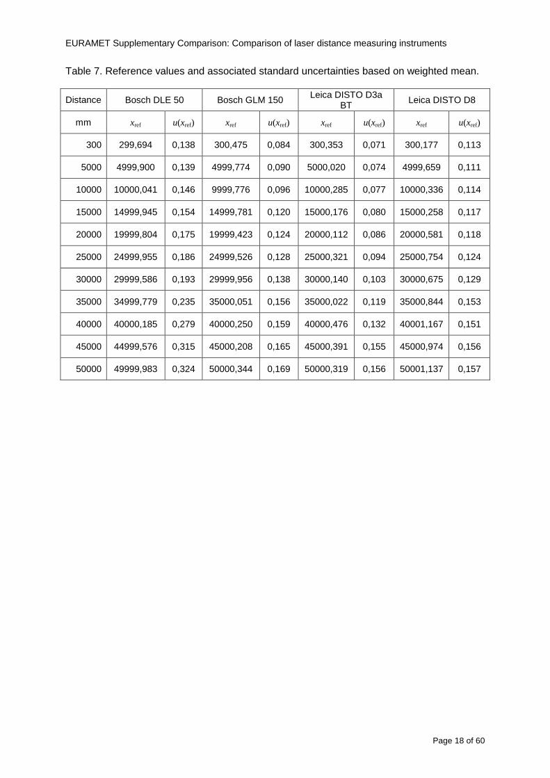
EURAMET Supplementary Comparison Comparison of laser distance measuring instruments
Page 19 of 60
10 Deviations from reference values The following figures show results from NMIs for all of the distances Reference value is represented by a bold black line
Bosch DLE 50
-30
-25
-20
-15
-10
-05
00
05
10
15
20
25
30
0 5 10 15 20 25 30 35 40 45 50 55
Length m
Dev
iatio
n fr
om n
omin
al le
ngth
m
m
MIKES
SP
Metrosert
PTB
CMI
SMU
INM
INRIM
CEM
BEV
JV
METAS
GUM
Ref
Bosch GLM 150
-20
-15
-10
-05
00
05
10
15
20
0 5 10 15 20 25 30 35 40 45 50 55
Length m
Dev
iatio
n fr
om n
omin
al le
ngth
m
m
MIKES
SP
Metrosert
PTB
CMI
SMU
INM
INRIM
CEM
BEV
JV
METAS
GUM
Ref
Fig 9 Deviations from reference values
EURAMET Supplementary Comparison Comparison of laser distance measuring instruments
Page 20 of 60
Leica DISTO D3a BT
-20
-15
-10
-05
00
05
10
15
20
0 5 10 15 20 25 30 35 40 45 50 55
Length m
Dev
iatio
n fr
om n
omin
al le
ngth
m
m
MIKES
SP
Metrosert
PTB
CMI
SMU
INM
INRIM
CEM
BEV
JV
METAS
GUM
Ref
Leica DISTO D8
-20
-15
-10
-05
00
05
10
15
20
0 5 10 15 20 25 30 35 40 45 50 55
Length m
Dev
iatio
n fr
om n
omin
al le
ngth
m
m
MIKES
SP
Metrosert
PTB
CMI
SMU
INM
INRIM
CEM
BEV
JV
METAS
GUM
Ref
Fig 9 Deviations from reference values (continued)
The deviations Di from reference value xref are calculated by
refxxD ii minus=
For calculating the expanded uncertainty of these deviations U(Di) the corresponding uncertainties u(xi) and u(xref) cannot simply be geometrically added because the values xi and xref are correlated Due to the random changes described in section 6 uncertainty u(dart) was added [2] It can be shown that the expanded uncertainty U(Di) is given by
)()()(961)( art2
ref22 duxuxuDU ii +minus=
when xi belongs to the largest consistent subset and
)()()(961)( art2
ref22 duxuxuDU ii ++=
EURAMET Supplementary Comparison Comparison of laser distance measuring instruments
Page 21 of 60
otherwise The deviations from the reference values are given in various figures and tables below The uncertainty bars in the figures correspond to the expanded uncertainties U(Di) (k = 196)
Fig 10 Deviations from reference values
EURAMET Supplementary Comparison Comparison of laser distance measuring instruments
Page 22 of 60
Fig 10 Deviations from reference values (continued)
EURAMET Supplementary Comparison Comparison of laser distance measuring instruments
Page 23 of 60
Fig 10 Deviations from reference values (continued)
EURAMET Supplementary Comparison Comparison of laser distance measuring instruments
Page 24 of 60
Fig 10 Deviations from reference values (continued)
EURAMET Supplementary Comparison Comparison of laser distance measuring instruments
Page 25 of 60
Fig 10 Deviations from reference values (continued)
EURAMET Supplementary Comparison Comparison of laser distance measuring instruments
Page 26 of 60
Fig 10 Deviations from reference values (continued)
EURAMET Supplementary Comparison Comparison of laser distance measuring instruments
Page 27 of 60
Fig 10 Deviations from reference values (continued)
EURAMET Supplementary Comparison Comparison of laser distance measuring instruments
Page 28 of 60
Fig 10 Deviations from reference values (continued)
EU
RA
ME
T S
upplementary C
omparison C
omparison of laser distance m
easuring instruments
P
age 29 of 60
Table 8 Deviations from the reference value (given at the top of the table) and expanded uncertainties (k=196) of such deviations for BOSCH DLE 50
Table 9 Deviations from the reference value (given at the top of the table) and expanded uncertainties (k=196) of such deviations for BOSCH GLM 150
EU
RA
ME
T S
upplementary C
omparison C
omparison of laser distance m
easuring instruments
P
age 30 of 60
Table 10 Deviations from the reference value (given at the top of the table) and expanded uncertainties (k=196) of such deviations for Leica DISTO D3a BT
Table 11 Deviations from the reference value (given at the top of the table) and expanded uncertainties (k=196) of such deviations for Leica DISTO D8
EURAMET Supplementary Comparison Comparison of laser distance measuring instruments
Page 31 of 60
11 En Tables Results with En gt 1 are marked with red color in Tables below En values are calculated by Di U(Di) with Di and U(Di) as given on page 19
Table 12 BOSCH DLE50
Lab Distance (mm) 300 5000 10000 15000 20000 25000 30000 35000 40000 45000 50000
MIKES -058 017 -019 -023 035 -002 -096 SP 020 019 006 005 009 059 064 037 028 097 001
Metrosert -030 -031 -003 018 032 PTB 001 029 022 -006 011 -036 001 -023 -075 -083 001 GUM -033 -005 -018 -009 000 006 017 005 -026 -028 019 CMI -003 020 -009 004 005 -022 028 SMU 006 -049 -034 -023 -017 -057 051 039 021 INM 032 031 037 006 020 005 -079 -119 -272 -260 -269
INRIM 025 -013 000 096 CEM -032 -022 -041 -039 -004 -038 080 001 -094 -047 BEV -010 007 000 -001 008 -011 037 013 -001 008 -001 JV -019 -016 025 -055 055 060 068 163 122 060 089
METAS 038 012 -005 007 -107 004 -024 002 -070 037 -052
Table 13 BOSCH GLM150
Lab Distance (mm) 300 5000 10000 15000 20000 25000 30000 35000 40000 45000 50000
MIKES 005 -002 019 018 027 019 062 SP 003 068 029 023 051 008 015 016 -005 -001 038
Metrosert -061 -011 -022 -021 -003 PTB 066 074 062 062 034 053 047 048 047 091 064 GUM -007 -014 007 -018 000 023 020 033 014 032 038 CMI -057 -032 -030 -064 -050 -047 000 SMU 023 -024 -060 012 062 001 -003 050 047 INM -022 017 -003 002 -003 054 005 -006 016 -022 -055
INRIM 079 -052 -050 -026 -034 -042 CEM 002 002 -034 -020 -029 -077 -077 -077 -074 -104 BEV -004 -002 -007 010 -042 -042 -029 -011 -028 -022 -030 JV 003 015 040 011 -020 021 -029 -005 028 036 058
METAS -047 -020 005 002 -012 -033 -054 -065 -053 -082 -040
Table 14 Leica DISTO D3a BT
Lab Distance (mm) 300 5000 10000 15000 20000 25000 30000 35000 40000 45000 50000
MIKES 008 094 050 -011 028 051 045 SP 033 038 056 017 053 065 076 051 017 071 011
Metrosert -060 -004 -037 -014 -002 PTB 067 000 070 030 089 062 061 081 124 050 072 GUM 023 019 035 008 038 053 029 058 070 064 063 CMI -001 -004 027 -011 011 034 -033 SMU 002 -013 -019 007 -013 -055 045 -013 -042 INM 002 -039 -058 001 002 -045 -080 -051 -102 -101 -378
INRIM 070 -020 063 101 CEM -028 -004 -004 -064 003 -002 -050 -022 -093 -160 BEV -032 -019 -019 004 -011 -037 -017 -002 -025 005 012 JV 027 019 027 042 046 039 043 048 072 115 024
METAS -091 -008 -102 -098 -111 -103 -092 -080 -073 -108 -043
EURAMET Supplementary Comparison Comparison of laser distance measuring instruments
Page 32 of 60
Table 15 Leica DISTO D8
Lab Distance (mm) 300 5000 10000 15000 20000 25000 30000 35000 40000 45000 50000
MIKES 025 013 058 036 038 061 022 SP 057 026 040 016 013 016 025 017 -007 -019 007
Metrosert -021 006 -016 -043 -019 PTB 040 011 035 -005 -011 -002 -004 035 047 022 069 GUM -028 005 -025 031 039 -015 029 048 041 052 072 CMI -104 -026 -072 -057 -006 -017 -015 SMU -067 -017 -051 -026 -016 -054 -004 -001 -016 INM 021 -014 009 003 -017 -031 -010 007 029 036 041
INRIM 076 -024 -004 047 -007 083 CEM 004 -009 002 -033 -051 -059 -097 -077 -116 -134 BEV -057 -014 -051 -093 -024 -027 -021 -036 -038 -028 -041 JV 014 031 047 030 044 043 035 056 093 108 030
METAS 035 007 026 038 -013 -024 -011 -048 -089 -074 -066
12 Conclusions It was the first comparison of EDMs For most of the laboratories it was an important opportunity to validate their measurement instrumentation and procedure It allowed to become aware of potential problems and to take corrective actions in changing the procedure
For the evaluation of the reference value the weighted mean approach has been chosen although the consistency check according to procedure A of Ref [1] failed in many cases A more complicated procedure for the evaluation of the reference value was proposed which slightly changes the uncertainty of the reference value
In total there were 23 En values larger than 1 This represents 47 of the full set of 482 results It is less than the 5 of possible values being out of the expanded uncertainty of the reference value for k=2
The uncertainty of the results mainly comes from the uncertainty of the reproducibility It is difficult to distinguish between Labrsquos calibration and measurement capability
The comparison shows a global compliance with declared CMCs independently of whether some participant can have a high percentage of values not compliant with its CMC due to the influence of the artifact and the estimation of its uncertainty
13 References [1] M G Cox The evaluation of key comparison data Metrologia 39 589 ndash 595 (2002)
[2] R Thalmann EUROMET 677 ndash Steel Tape Measures Final report (2004)
[3] F Pollinger personal communication
EURAMET Supplementary Comparison Comparison of laser distance measuring instruments
Page 33 of 60
Appendix 1 Description of the measurement equipmen t as reported by the laboratories
A11 MIKES Finland
Short description of measurement bench
MIKES interferometric bench is situated in an underground laboratory with air temperature and humidity control Typically air temperature is 20 plusmn 01 degC and humidity 45 plusmn 2 RH The linear guide on the top of the concrete beam comprises two parallel round shafts with adjustable fixtures every 1 m A carriage with ball bush bearings is moved along the rail and location of it is measured with reference interferometer HP-5529A Temperature of air is measured with 6 pt100 sensors and Keithley 2010 multimetre with 4-wire resistance mode Air pressure and humidity are measured with Vaisala PTU200 Updated Edleacuten equation by Boumlnsch amp Potulski is used for calculation of refractive index of air
For EDM calibration on the other end than laser interferometer is a fixed reference plate which is adjusted perpendicular to the laser beam Next to the reference plate is an adjustable base for EDM instrument with which it can be adjusted to point parallel and coincident with measurement arm of the interferometer A target plate adjusted perpendicular to laser beam is fixed to the carriage The calibration followed Abbe principle with some millimetre uncertainty in offset adjustment
First reference interferometer is set to zero when the target plate and reference plate are in contact then EDM is positioned and adjusted in its base The rear surface of the EDM is also slightly pressed against reference surface behind it Then the readings from both instruments are collected at selected locations For this calibration there is no fine adjustment of the target position so there are typically deviations of up to few millimetres from nominal locations Results are averages of 3-4 measurements
Additional remarks
The CMC entry MIKES has for EDM calibrations is based on calibration of length scales of high quality total stations and laser trackers This type of EDMs used in this comparison are not accurate enough for truly testing of MIKES calibration measurement capability
EURAMET Supplementary Comparison Comparison of laser distance measuring instruments
Page 34 of 60
A12 SP Sweden
Short description of measurement bench
The bench consists of a simple aluminium Uminusshaped profile with polished steel pins acting as supports for the tape The bench is a little over 50 m long and works as support for the reference tape and the calibrated EDMs simultaneously
Length measurement instrument
Comparison with reference steel tape
Temperature measurement system number and location of sensors
The tape temperature is continuously registered in 6 points equally distributed along the bench The air temperature is monitored during the measurements but not used for corrections
Additional remarks
The EDM support is placed approximately 2 cm vertically above the tape No visual aid is used
EURAMET Supplementary Comparison Comparison of laser distance measuring instruments
Page 35 of 60
A13 AS Metrosert Estonia
Short description of measurement bench
The 21-m bench is located in the designated corridor-like laboratory room The lab is air-conditioned and the stability of temperature is typically plusmn05 ordmC There are three humidity and temperature sensors in room for stability and gradient monitoring
Two stainless steel rails running in parallel are made of 3-m long rods The rails lay without fixed attachment on metal supports which are mounted on concrete base The base rests on pillars made of bricks
Length measurement instrument
Laser-interferometer system Renishaw ML10 was used as length measurement instrument
Laser interferometer gets temperature humidity and pressure data from itrsquos own measurement system EC10
Additional remarks
Due to the length of the bench only measurements up to 20 m could be made Five measurement series were made with each EDM
EURAMET Supplementary Comparison Comparison of laser distance measuring instruments
Page 36 of 60
A14 PTB Germany
Short description of measurement bench
The measurements were performed on the 50 m geodetic base of the PTB The comparator consists of a 50 m rail The laboratory is equipped with a network of 21 temperature sensors spaced by 25 m along the bench As depicted in fig 1 the EDM is mounted at one end of the comparator the reflector is fixed vertically on the carriage A large retroreflector is mounted approximately 150 mm below the EDM reflector on the carriage reflecting the beam of the reference interferometer The deviation of the length due to tilting carriage (Abbe error) has been investigated along the bench by comparison of two interferometers It remains smaller than 100 microm The distance of the first position of 300 mm with respect to the back side of the EDM is determined by a gauge block of 300 mm length and a thickness of 10 mm This procedure is depicted for one of the comparison standards in figure 2
For the calibration the desired positions are programmed After the carriage reaches a measurement position the operator waits for another 30 s for the carriage to settle In control experiments the remaining movement between positioning and measurement remained smaller than 2 microm The operator then activates the measurement of the EDM reads the indicated position and writes it down The procedure is repeated for twelve times at every position the mean of the 12 measurements represents the ldquoindicated distance by the EDMrdquo All measurements of a single run at one position are performed within approximately one minute The complete measurement was repeated for four times
Length measurement instrument
The reference length is determined by a frequency-calibrated laser interferometer (Agilent 5519A) The reference interferometer is set up in Michelson geometry the signals being digitalised by a Heidenhain IK 121 card The index of refraction is determined by the external weather station of the geodetic base consisting of 21 Pt-100 temperature sensors spaced 25 m along the bench two humidity sensors (Testo 650) and two pressure sensors (Setra 370 and DPI 141) The environmental parameters are used to determine the index of refraction for the reference measurement deploying the modification of the Edleacuten equation by Boumlnsch and Potulski
EURAMET Supplementary Comparison Comparison of laser distance measuring instruments
Page 37 of 60
A15 CMI Czech Republic
Description of measurement bench
The EDMs were measured on 30 m long measuring bench equipped by laser interferometer (LI) Renishaw ML10 (pic 1 and 2) calibrated traceable to national standard of length and quantities of environmental sensors The target plate and retroreflector of the LI were fixed on a moving part of the bench and each EDM was fixed in horizontal position by clamps (pic 3) LI and EDM are placed on opposite ends of bench the Abbe offset was lt10 mm for some of them and lt50mm for all The value of LI was reset (to zero) at position corresponding to the rear of the EDM (using 3D measuring arm FARO Quantum with uncertainty about 27microm) The perpendicularities of the EDM stop as well as target plate to the beam were also checked by FARO) Each EDM was 3x replaced and aligned the measurement (reading) was repeated 6 times for each alignment and position the mean value of these 3x6 measurements is stated in tables with results The uncertainty claimed covers the statistical uncertainty of single readings Only in case of Leica D8 (the best performing EDM in this comparison) we state also the uncertainty corresponding to the mean of 6 readings in last column (this uncertainty is smaller and better illustrates our CMC)
Length measurement instrument
- Laser interferometer Renishaw - Laser 633 nm Type ML10 - Compensator EC10 - 3D measuring arm FARO Quantum - 3D measuring arm FARO Quantum
EURAMET Supplementary Comparison Comparison of laser distance measuring instruments
Page 38 of 60
A16 SMU Slovakia
Short description of measurement bench
No bench is available at the SMU the measurements are being carried out in the underground corridor of the laboratory building with length of 428 m
The 50 m steel measuring tape KINEX was used as the reference laid on the floor and pulled by the force 50 N (the same force as had been applied during its calibration at the SMU) The calibration of reference tape was done at the SMU using ULM3m Zeiss with laser interferometer Agilent 5529 B (ie per 3 m parts)
Three mercury thermometers with the resolution of 01 degC were used along the measurement path each of them laid onto the tape and located at 667 m 1990 m (instead of 20 m because of this was one of measuring points) and 333 m respectively Each of them thus corresponded approximately to one third of the measured steel tape section
Regarding the 03 m measuring point the ULM3m Zeiss length measuring machine was used with the 300 mm gauge block as the reference
Length measurement instrument
We used our own target plate being fixed perpendicularly (within uncertainty stated) to the construction equipped with nonius and the camera holder transported manually along the steel tape The second construction was fixed to the tape by such a way that zero line of the tape corresponded to the rear of EDM (within uncertainty stated)
The position of the target is read on the monitor and 20 repeated readings of the EDM data took place in each measuring point (multiples of 5 m up to 40 m)
Concerning 03 m the 300 mm gauge block was fit between the target plate and the construction with EDM The distance of the EDM rear from the target plate corresponded to the length of gauge block (within uncertainty stated)
Additional remarks
The identical measurement method was used as we use to do within our calibration service although the results reporting is different ndash we provide the regression line calculated from the measurement of irregularly distributed points and corresponding uncertainty (k = 2) in the form of [a bL] mm (ie the same coefficients for each length in the range (0 ndash 42) m)
SMU hasnrsquot got this category in CMC tables
EURAMET Supplementary Comparison Comparison of laser distance measuring instruments
Page 39 of 60
A17 INM Romania
Short description of measurement bench
Geodesic base located in the basement of the laboratory with nominal length equal to 50 m having a mobile carriage thet support both laser He-Ne retroreflector and the target of the laser distance measuring instrument in the front of geodesic base exists a support where are aligned both laser interferometer and the laser distance measuring instruments
Length measurement instrument
Laser interferometer type Hewlett Packard model 5526 A with nominal length equal to 50 m resolution 0001 mm
U = 02 microm +0510-6L
Additional remarks
During the measurements the maximum gradient of temperature was equal to 05 degC
EURAMET Supplementary Comparison Comparison of laser distance measuring instruments
Page 40 of 60
A18 INRIM Italy
Short description of measurement bench
The facility for long distance measurements is located in a corridor of the gallery devoted to dimensional metrology The structure consists in a 28 m long rail fixed to a series of pillars which rest directly on the ground released from the vibrations of floor and wall The measuring system is based on a heterodyne interferometer whose mobile arm consists of a hollow retro-reflector mounted on a structure that can run along the rail so-called carriage A photograph of the facility is presented in Fig1
The carriage is moved by a micro-step motor the motor driver receives a digital pulse and converts it into an electrical pulse to run the motor Each pulse causes a rotation of the motor shaft of one step which amounts to 11000 of a complete revolution of the shaft If the pulse frequency increases the rotation becomes continuous with a speed that is directly proportional to the pulse frequency The speed ranges between few microms up to 27 ms with a resolution of 03 microms
Since the carriage must move back and forth automatically for a distance of almost 30 m a remote control to send pulses to the motor driver was implemented It consists of two parts a radio command which allows to set some general parameters of the carriage movement such as the movement direction and mode of travel (slow or fast) and a fast command which is performed by an amplitude modulated laser beam placed at the beginning of the track oriented towards the carriage A photo detector placed above the carriage receives the modulated laser beam which is transformed into pulses to be sent to the driver of the motor The modulation of the laser beam is implemented by a LabView program that controls a digital output of the data acquisition device
Length measurement instrument
The length measurement instrument is based on a heterodyne incremental interferometer The main beam of the interferometer with frequency f1 is generated by a frequency stabilized
EURAMET Supplementary Comparison Comparison of laser distance measuring instruments
Page 41 of 60
He-Ne laser calibrated with respect to the INRIM length standard and sent to the measurement arm the second beam is a portion of the first one diffracted by an acousto-optic modulator (AOM) with frequency f2 = f1 + 80 MHz The reference detector acquires the beat note signal at 80 MHz while the measurement detector acquires a signal at 80 MHz whose phase is varied due to the displacement of the retro-reflector moving on the rail In figure 2 the optical design of the interferometer is presented
Two different measuring techniques have been implemented
1 the ldquophase measuringrdquo technique based on fringes counting with a relative uncertainty of 5middot10-7 but limited at the maximum carriage speed of 3 cms
2 the ldquoDoppler frequency measurementrdquo technique for higher carriage speed based on the measurement of the Doppler frequency shift while the carriage runs
The second technique was validated by means of the comparison with the first technique at low speed with an agreement of the order of 3middot10-6 hence the Doppler frequency method could be considered validated within 01 mm over the whole rail path with the advantage of reducing the time needed to cover long distances so it was used for the EDM comparison
In order to obtain the distance covered by the carriage according to technique 2 the Doppler frequency is measured by a commercial high-performance counter (a Pendulum CNT-90) without dead time based on time stamping then it is converted in speed and integrated over time according to the following formula
( ) ( )int minus=minus= tffn
dtn
ffdairair
λλ
2
1
2
1
where d is the distance covered by the carriage f is the frequency of the measuring signal with the carriage at rest frsquo the frequency of the measuring signal with the carriage moving λi
is the wavelength of the laser in vacuum n - air is the air refractive index and ti is the integration time The difference frsquo-f is just the Doppler frequency due to the moving carriage
The time interval measurement resolution of the instrument is 100 ps and the time base is
EURAMET Supplementary Comparison Comparison of laser distance measuring instruments
Page 42 of 60
connected to the INRIM UTC so that the measurements of the Doppler frequency and the integration time are extremely accurate The environmental parameters such as air temperature atmospheric pressure partial pressure of water were monitored during the measurement process in order to calculate the value of air refractive index according to the Edlenrsquos formula
Comparison set-up
The different technical solutions adopted for the EDMs and for the target plate positioning are discussed in this paragraph and sketched in figure 3
Fig 3 picture of the EDM and target positioning area
Target plate positioning
In order to use the provided target plate an ad-hoc mounting was manufactured at INRIM it consists in a sort of picture frame made in aluminum which slightly clamps the target folded in half and gives it the necessary stiffness to be a reproducible target The upper part of the frame is L-shaped and allows it to be fixed to the carriage structure by means of two screws The rear part of the target mounting is depicted in figure 4 The target mounting was considered necessary because of the poor stiffness and planarity of the plastic target With the aluminium frame a planarity better than 01 mm was guaranteed The target plate is placed few centimetres next to the retro-reflector and normal to the interferometer beam axis since the EDM laser should be as close and parallel as possible to the reference beam
EURAMET Supplementary Comparison Comparison of laser distance measuring instruments
Page 43 of 60
Fig 4 picture of the rear part of the target plate mounting
EDMsrsquo positioning
The EDMs are placed on a cradle-like platform which is able to adjust the inclination of the EDM along the longitudinal axis (pitch angle) The platform height allows the EDMs to be at approx the same height as the interferometer beam A crucial role was played by the stop-wall placed behind the platform since it represents the ldquozero pointrdquo for all the length measurement Hence a particular effort was devoted to align the stop-wall so that it was normal to the interferometer beam axis and parallel to the target plate
Fig 5 detail of EDMsrsquo positioning the cradle-like platform and the stop-wall are well visible
EURAMET Supplementary Comparison Comparison of laser distance measuring instruments
Page 44 of 60
Target and stop-wall alignment
In order to have the stop-wall parallel to the target plate and normal to the interferometer beam axis the following procedure has been used
1) the stop-wall and the target plate were roughly placed trying to set them parallel and normal to the rail by eye (ie within few millimeters)
2) in order to check if the target was normal to the rail one EDM was positioned on the platform the pitch and yaw angles of the EDM were adjusted by observing the position of the EDM laser spot on the target plate when the target is moved along the rail fixed position means laser beam parallel to the carriage movement Then the target was moved until the end of the rail and a thin mirror was kept in contact with it hence observing the EDM laser reflected by the mirror it was possible to adjust the target tilt acting on the screws until the laser beam is reflected back to the source
3) finally in order to check the parallelism between the stop-wall and the target a tool made by a laser pointing orthogonally to its base was used the base was leant against the stop-wall and the laser was centered on the target when the target is near then the target was moved until the end of the rail hence observing the spot of the laser on the target it was possible to adjust the stop-wall orientation
The residual misalignment errors which we were not able to eliminate were kept into account in the uncertainty budget
Measurement of the first 30 cm
Due to the geometry of our set-up it was not possible to perform the first point of measurement by means of the interferometer indeed the carriage (hence the target) is not able to go in contact with the stop-wall
Fig 6 measurement of the first 30 cm the ruler touching the stop-wall and the target and the mechanical probe (in the back) touching the carriage are visible
EURAMET Supplementary Comparison Comparison of laser distance measuring instruments
Page 45 of 60
So a ruler made of aluminum with rounded ends and nominal length equal to 30 cm was adopted to set the distance between the target plate and the stop-wall for the first point of measurement as it is shown in figure 6 The ruler whose length was measured by a CMM machine was inserted between the target and the stop-wall leaning against the latter and the carriage was carefully moved towards the stop-wall until the target lightly touched the ruler A mechanical probe that touches the carriage structure when carriage is in the ldquo30 cmrdquo position was used as a reference measurement to check the repeatability of this distance after each measurement set
Fig 7 detail of the mechanical probe touching the carriage
Environmental parameters
The environmental parameters such as air temperature atmospheric pressure and humidity were monitored during the whole measurement process in order to calculate the value of air refractive index according to the Edlenrsquos formula
Among these parameters the temperature distribution along the mobile arm of the interferometer was our main concern mainly for two reasons
1 the temperature control of the gallery was not perfectly working during the measurement period so temperature drifts had to be monitored
2 longitudinal temperature gradients due to non uniform heating and to the presence of electronic instruments were pretty high
To the purpose 14 thermometers were uniformly dislocated along the rail and automatically recorded for all the measurement period Both temporal drifts and gradients along the path have been taken in account in the uncertainty budget In any case maximum temperature differences along the rail are within 1 degC In fig 8 an extract from the acquisition file is shown
Unfortunately the air conditioning system did not work well during the measurement campaign hence the measurements were performed at a mean temperature of 209 degC
EURAMET Supplementary Comparison Comparison of laser distance measuring instruments
Page 46 of 60
Fig 8 each curve represents the temperature distribution along the rail during the measurements campaign
Carriage waving
Since the rail is not perfectly straight and the measurement laser is not coincident with the measurement beam the Abbegrave error due to waving of the target must be considered A quantitative measurement and a qualitative measurement were carried out With an electronic level placed on the carriage the straightness on the vertical plane has been mapped with a half meter resolution (the data are reported in fig 9) With a laser placed on the carriage the horizontal and vertical waving are qualitatively compared by looking at the movements of the light spot on a target fixed to the rail end As a conclusion the horizontal and vertical waving are comparable in magnitude and the peak to peak error is of the order of 300 arcseconds
Fig 9 vertical waving of the target measured by an electronic level placed on the carriage
EURAMET Supplementary Comparison Comparison of laser distance measuring instruments
Page 47 of 60
Measurement procedure
The measurements were carried out according to the following procedure
The target was set in the starting position with the procedure described above
In sequence the four EDMs are positioned on the base the horizontal and vertical tilt are adjusted and the distance measurement is recorded An additional fifth EDM (Bosh DLE 150 property of INRiM) was included in the measurement sequence Each EDM is placed on the base and gently pushed against the reference wall in such a way that the measurement laser beam starting point is the same for all EDMs Than the horizontal and vertical angles were adjusted in order to hit the central point of the target indicated with two black marks (see pictures 3 and 6) with ldquovisualrdquo alignment The measurement button is then pressed several times (typically 5) and the average reading is recorded Typical dispersion between readings is within few last digit units In case the dispersion between readings is too large the anomaly is recorded
The carriage was then moved in the next position (about 5 m) and the measurement sequence was repeated for the 5 EDMs The operation is repeated up to 25 m The 25 m measurement is than repeated again as well as all the points till the first one so that each point is measured twice each set Since the carriage movement is ldquoopen looprdquo the positioning of the carriage was not exactly in the nominal 5 m intervals For each positioning the incremental displacement is measured by the interferometer in the Doppler mode Finally the measured values were averaged in order to give a single value for each nominal position
At the end of the measurement set when the carriage is at the 30 cm position again the sum of the interferometric measurements should be very close to zero The residual value is compared with the difference between the first and the final measurements of the mechanical probe The difference must be within the uncertainty of the Doppler technique otherwise some error occurred in the measurement set that must be repeated
At the end of the session 10 complete sets of measurements recorded from the 20th to the 30th of January 2012 have been considered for this report
Additional remarks
Effect of laser pointing
During a preliminary set of measurements we noticed a strong and unexpected dependence of the measurement result on the position of the laser spot on the target Indeed since no particular instructions were given about the relative position of the laser spot on target position (except to exclude the central joint between the two halves) we decided to work relatively close to the right side of the target -closer to the interferometer beam- in order to reduce the Abbegrave error We noticed very large errors at large distances in particular of the Leica DISTO D3a (see figure 10)
EURAMET Supplementary Comparison Comparison of laser distance measuring instruments
Page 48 of 60
Fig 10 errors of each EDM In a preliminary set of measurements
We also noticed that this error was strongly dependent on the position of the spot on the target For this reason we carried out a set of measurements at the maximum length in different positions of the target from one edge to the other according to figure 11 The results are reported in table V
EDM A B C D E
Leica D3a -4 +1 0 +24 +43
+2 0 +42 +40
-1 0 +38
Leica D8 0 0 0 2 +7
0 +12 +23
table V deviations (in mm) from the length measured at point C aiming the laser spot at different positions of the target (notations as in figure 11)
We tried to find an explanation to this effect in the shape of the laser spot if the spot was
EURAMET Supplementary Comparison Comparison of laser distance measuring instruments
Page 49 of 60
particularly defocused or had high diffraction some of the energy could fall out of the target and affect the measurement result In fact the images of the spots (shown in fig 12) do not support this hypothesis Finally we decided to use the center of the (half) target for the comparison
Changing the target
In order to investigate the influence of the target on the measurements a cardboard foil (400 x 400) mm was fixed to the target mounting and a complete set of measurements was performed The results reported in figure 13 and 14 do not show any evidence of a possible dependency of the EDM measurement on the target kind
EURAMET Supplementary Comparison Comparison of laser distance measuring instruments
Page 50 of 60
Measurement at 50 m
Although we are not able to perform traceable length measurements beyond 28 m we wanted to get a sense of EDMs behaviour at longer distances So a target (represented by a rack side wall) was placed at approximately 50 m one after the other the EDMrsquos were positioned on the base and pointed towards the target The measurements were repeated then the target was replaced by the target used for the comparison and a third set of measurements were performed To our great surprise all the EDMrsquos were in good agreement (within 2 or 3 mm for each set of measurement) even those which showed errors of the order of five to ten millimeters at 25 m namely BOSCH DLE 50 and LEICA DISTO D3a Therefore each set of measurements was averaged and the deviations from the mean value are reported in figure 15
EURAMET Supplementary Comparison Comparison of laser distance measuring instruments
Page 51 of 60
Fig 15 Deviations from average value of the measurements At 50 m
EURAMET Supplementary Comparison Comparison of laser distance measuring instruments
Page 52 of 60
A19 CEM Spain
Short description of the measurement bench
To make the measurements of EDMs we have used a reference line made of adjustable supports fixed on a wall of the laboratory Each support is nominally separated five metres from the previous one so we can generate reference lengths up to fifty metres with a pitch of five metres The supports are designed to accommodate both targets and handheld EDMs Distances between supports were measured by using a total station traced to national standards The relative angles of the bases have been measured and corrected
Fig 1 - View of three consecutive supports of the 50 m baseline (left) Lab technician situating an EDM on the first support of the baseline (right)
Length measurement instrument
The baseline was calibrated by using a total station Leica TDA5005 with spherical reflector the calibration uncertainty being 02 mm for k = 2
The target is provided by the comparison The quality of the target was judged as not good due to geometrical constructive errors and the lack of rigidity and stability We measured the flatness of the target surface the distance edge-surface and the angle between them by using a 3D coordinate measuring machine The results of flatness and angle were included in the uncertainty budget and the distance EDM-target was corrected for each EDM due to each beam impinged on a different point of the target
We were not able to measure the distance 0 to 03 m because the baseline pitch is 5 meters and although we are able to measure shorter values in a different facility the target was not appropriate for our bench
EURAMET Supplementary Comparison Comparison of laser distance measuring instruments
Page 53 of 60
Fig 2 - View of an EDM on the first support of the baseline (left) A closer look showing the support adjustments and the origin plate (right)
Fig 3 - View of the comparison target on one of the supports of the baseline (left) A closer look showing the target edge against the support rigid reference (right)
Measurement method
The measurements were carried out by comparison against the known values of the calibrated baseline (metallic references on supports)
Environmental conditions were maintained within the following limits
- Temperature 20 ordmC plusmn 05 ordmC
- Humidity 45 plusmn 10
Each laser distance measuring instrument was placed at the first support of the base and aligned so that the laser beam was perpendicular to the target as indicated by the comparison protocol
For each measurement we took the average of thirty measurements It permitted us to evaluate the repeatability of the instrument
EURAMET Supplementary Comparison Comparison of laser distance measuring instruments
Page 54 of 60
A110 BEV Austria
Short description of the measurement bench
Fig 1 Carriage of tape bench View from the laser interferometer side Retroreflector mounted on the vertical plate the EDM target is mounted on the backside
Fig 2 Support for the DUT Adjustable with 2 translational and 2 rotational degrees of freedom respectively
Fig 3 Setting of the 300 mm starting position Note the rough-and-ready mounted target plate
Fig 4 Laser interferometer side of the bench The DUT is 50 m away on the other side
EURAMET Supplementary Comparison Comparison of laser distance measuring instruments
Page 55 of 60
Measurement procedure 1 The EDM is positioned with the help of a 4-axis positioning stage so that its laser beam is
coaxial with the measurement direction of the laser interferometer (in head on configuration)
2 The EDM is removed from its support The bench carriage is positioned so that the distance of the target plate from the EDM back support is 300 mm A length bar with spherical faces is used for this adjustment The laser interferometer is preset to 300 mm and the EDM is put back on its support
3 At each position 10 consecutive measurements are taken (repeatability) and the carriage is moved to the next position The carriage is manually moved under control of the laser interferometer until it is within plusmn30 microm at the correct position (Exception for the DLE 150 the target is not positioned at 10 m but at 10 m ndash 1 mm to make use of the higher resolution) The indicated (not the nominal) distance of the laser interferometer is recorded for the determination of the deviation
4 After reaching the 50 m position all points are measured in reverse order (bidirectional) Immediately after the last measurement the EDM is removed and the indication using the 300 mm length bar is checked (thus noting a possible drift of the setup)
5 Each instrument was measured 4 times according to this procedure on different days (reproducibility of bench and instrument)
Length measurement instrument
Agilent laser interferometer with long range option The bench was completed short time before performing these measurement So the characterisation was not complete and the respective measurement uncertainty of the laser interferometer is estimated rather high But anyway its contribution to the overall uncertainty can nearly be neglected
Additional remarks
The uncertainty originating from the DUT is the dominating uncertainty contribution Specifically the resolution of the two Bosch instruments (1 mm) and the repeatability are the largest contributions For the DLA 50 the pooled standard deviation of a reading at 50 m is larger than 2 mm Moreover the length dependence is not a simple function
All of the instruments show a significant deviation of the laser beam from the normal of the back (reference) face of the instrument The measured angles reach from 04deg (D3a) to 11deg (DLE 50) This leads depending on the outer dimensions of the instruments to a constant uncertainty contribution of 02 mm in our setup It must be noted that the reference faces are not well defined in most of the instruments
The reproducibility is quite different for the four instruments so only part of it originates from the setup For CMC claims we will use the standard uncertainty value of the most reproducible instrument (D3a) which amounts to 013 mm For an ideal instrument with a resolution of 01 mm and perfect repeatability we would thus have a constant expanded uncertainty of 053 mm up to 50 m
EURAMET Supplementary Comparison Comparison of laser distance measuring instruments
Page 56 of 60
A111 JV Norway
Short description of measurement bench
EDM under calibration and the reference system are aligned along a 50 m measurement bench with rails to carry the linear movement of a target plate for the EDM and a corner cube reflector for the reference system The distance between parallel axis of EDM and axis of the reference system is 130 mm Abbe error due to angle errors for the movement is smaller than 01 mm and is corrected for at each measurement point At long lengths an aperture is used approximately midway between the target plate and the EDM to avoid interfering stray light to the EDM
Alignment procedure
1) Alignment of reference system to the movement of the carriage (rails)
2) Alignment of the EDM to the movement of the carriage (rails)
3) Alignment of a plane mirror at the position of the target plate using back-reflection to the EDM output (normal incident of light on the mirror)
4) Take out the EDM and align the zero reference plate at the back of the EDM to the plane mirror
5) The mirror is replaced by the target plate and the target plate is aligned to the zero reference plate
6) Zero setting of the reference measurement system when target plate is at zero distance to the reference plate at the back of the EDM
7) Put the EDM back in position and realign it to the movement of the carriage (rails)
8) Zero setting of the EDM to the reference plate
Image 1) Image 2) Image 3) Image 4)
Image 1) Items 5) ndash 6) in alignment procedure
Fixture for HP linear interferometer is seen bottom right Part of Wyler instrument is seen to the left blue colour
Image 2) Items 7) and 8) in alignment procedure
Micrometer screws for angle alignment in two directions and linear translation for zero setting of the EDM Push button on the EDM is positioned at the tilting point of the angle adjustment table to maximize stability during measurement HP 5519 A laser head is seen to the right
Image 3) Ready to measure at selected distances from zero point the reference plate
Image 4) EDM spot size at 50 m
Length measurement instrument
- Hewlett Packard Dynamic Calibrator 5519 A (max range 80 m)
- Pressure air temperature humidity Vaisala
EURAMET Supplementary Comparison Comparison of laser distance measuring instruments
Page 57 of 60
- Digital high resolution angle measurement Wyler
I used our own target plate which is of the same type as enclosed in the artefact suitcase article number 766560 from Leica but with reduced size width x hight = 90 x 137 mm
The zero reference plate is of similar type and size
Before measurements batteries of EDMs were switched to new batteries Old batteries are switched back after calibration
For L gt 5 m an aperture of similar size as the target plate is used approximately midway between the EDM and the target plate
Additional remarks
Reports on EDM indicated values at each measurement point is the average value of n = 5 repetitions A linear model of the standard deviation for the repeatability of the EDM readings at different lengths is estimated using m = 20 repetitions at least 5 positions along the scale An estimate of the length dependent repeatability is made for each instrument
The expanded uncertainty U(95) is rounded up to the limiting resolution of 1 mm in the interval 10 m to 40 m for Bosch GLM 150
After the calibration we also estimated the angle error of the optical axis of the EDM to its back plane (back reference of EDM) Bosch DLE 50 26 mrad up measured at 50 m Bosch GLM 150 8 mrad to the left measured at 50 m Leica DISTO D3a 37 mrad down measured at 20 m Leica DISTO D8 2 mrad to the left and 4 mrad down (45 mrad total) measured at 20 m
The distance between parallel walls will be measured too large if the back plane is assumed to be normal to the optical axis of the EDM by ∆LL = (1cosα ndash 1) Bosch DLE 50 ∆LL = 340 ppm (∆L = 17 mm at L = 50 m) Bosch GLM 150 ∆LL = 32 ppm (∆L = 16 mm at L = 50 m) Leica DISTO D3a ∆LL = 7 ppm (∆L = 034 mm at L = 50 m) Leica DISTO D8 ∆LL = 10 ppm (∆L = 05 mm at L = 50 m)
EURAMET Supplementary Comparison Comparison of laser distance measuring instruments
Page 58 of 60
A112 METAS Switzerland
Short description of measurement bench (photo recom mended)
50 m bench with laser interferometer (see photo detailed description in Michel Degoumois Un Long laboratoire de mesure OFMETinfo Vol5 No 2 1998)
Length measurement instrument
HP 5529 B laser interferometer range 80 m
EURAMET Supplementary Comparison Comparison of laser distance measuring instruments
Page 59 of 60
A113 GUM Poland
Short description of measurement bench
The 50 m bench is situated in the corridor laboratory located in the basement and has its own air conditioning system with air temperature 20 plusmn 1 degC and humidity 50 plusmn 10 RH The measuring carriage is carried microscope with CCD camera and the optics associated with the interferometer The carriage is driven using belt-transmission and electrical engine with remote ndash controlled variable speed drive
The EDM was placed on the fixed adjustable plate on the other end than laser interferometer The target plate of the EDM was placed on the measuring carriage For each EDM 3 series of measurement were done Before the each measurement EDM was repositioned and aligned again
Length measurement instrument
1 Laser interferometer HP 5529A with long-range option laser head HP 5519A
2 Ambient measurement system number and location of sensors - 20 air temperature sensors type YSI with KEITHLEY multimeter they are placed very
close to axis of the laser beam - air pressure and humidity are measured with Vaisala barometer and
thermohigrometer - CO2 content was measured with analyzer made by Intelli Charge type SPN 4462
EURAMET Supplementary Comparison Comparison of laser distance measuring instruments
Page 60 of 60
Appendix 2 Corrections of reports
131 CEM Spain
CEM reported two errors in their report
1) Bosch GLM 150 EDM error for 35 m should be -08 mm instead of the indicated 08 mm
2) Leica DISTO D8 EDM error for 35 m should be -019 mm instead of the indicated 019 mm
Proposed corrections have been included in Tables 2 and 4 of the Final Report
132 AS Metrosert Estonia
AS Metrosert reported mixed up of all results for Bosch DLE 50 and Bosch GLM 150 The results and uncertainties sent for DLE 50 was results for GLM 150 and vice versa
Proposed corrections have been included in Tables 1 and 2 of the Final Report
133 INRIM Italy
Among the data reported from INRIM some anomalies were found in the measurements of BOSCH DLE 50 and LEICA DISTO D3a at distances of 20 and 25 m
After preliminary discussion on Draft A it was understood that those anomalies could be explained as a sensitivity of said instruments to the laser light that once diffused by the target is reflected by surfaces parallel to the measurement axis and detected together with the wanted signal The superimposition of the two signals can cause a ldquopullingrdquo effect leading to an overestimation of the distance being the reflected path always longer than the direct one Indeed in the INRIMrsquos set-up the target was mounted pretty close to the flat rail used for the carriage movement being likely responsible for unwanted reflections that disturbed the measurements
Since the errors reported in INRIMrsquos measurements can be ascribed to a defect of BOSCH DLE 50 and LEICA DISTO D3a andor to a lack of description of the working conditions of said instruments INRIM asked to eliminate its measurement points at 20 and 25 m of said instruments from the comparison
Proposed corrections have been included in Tables 1 and 3 of the Final Report
134 JV Norway
Justervesenet has changed the procedure and introduced two apertures instead of only one aperture (iris) which was positioned at half distance between EDM and target The reason is that the reference beam also has an aperture and it is positioned right below the beam from the EDM (130 mm distance between axes) Some diffusively reflected stray light from the EDM target might enter the aperture for the reference beam reflect at the measurement table and reach the detector of the EDM In our calibration set-up we have only seen problems at L gt 30 m We will position the first aperture at ca 5 m from the EDM and then the second aperture at ca 25 m This combination of two apertures will effectively eliminate interference of stray light from the measurement table to the EDM detector for all lengths up to 50 m
Justervesenet also increases the uncertainty component regarding repeatability reproducibility so that the expanded uncertainty increases from 14 mm to 15 mm
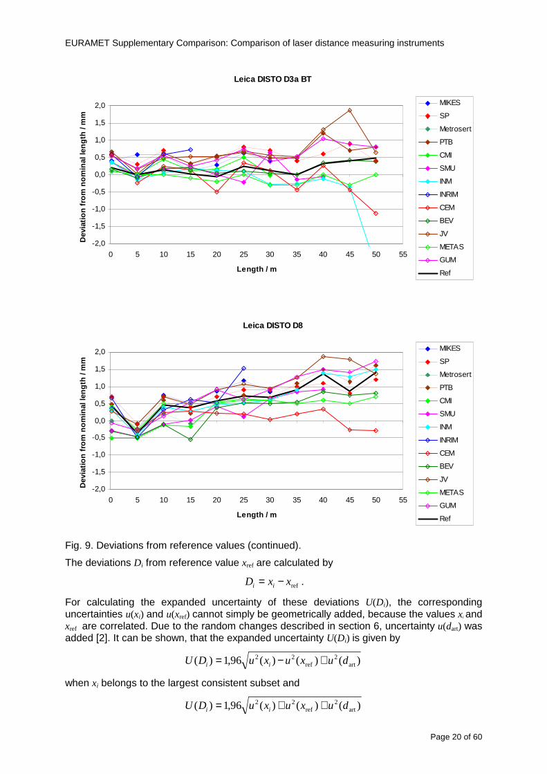
EURAMET Supplementary Comparison Comparison of laser distance measuring instruments
Page 20 of 60
Leica DISTO D3a BT
-20
-15
-10
-05
00
05
10
15
20
0 5 10 15 20 25 30 35 40 45 50 55
Length m
Dev
iatio
n fr
om n
omin
al le
ngth
m
m
MIKES
SP
Metrosert
PTB
CMI
SMU
INM
INRIM
CEM
BEV
JV
METAS
GUM
Ref
Leica DISTO D8
-20
-15
-10
-05
00
05
10
15
20
0 5 10 15 20 25 30 35 40 45 50 55
Length m
Dev
iatio
n fr
om n
omin
al le
ngth
m
m
MIKES
SP
Metrosert
PTB
CMI
SMU
INM
INRIM
CEM
BEV
JV
METAS
GUM
Ref
Fig 9 Deviations from reference values (continued)
The deviations Di from reference value xref are calculated by
refxxD ii minus=
For calculating the expanded uncertainty of these deviations U(Di) the corresponding uncertainties u(xi) and u(xref) cannot simply be geometrically added because the values xi and xref are correlated Due to the random changes described in section 6 uncertainty u(dart) was added [2] It can be shown that the expanded uncertainty U(Di) is given by
)()()(961)( art2
ref22 duxuxuDU ii +minus=
when xi belongs to the largest consistent subset and
)()()(961)( art2
ref22 duxuxuDU ii ++=
EURAMET Supplementary Comparison Comparison of laser distance measuring instruments
Page 21 of 60
otherwise The deviations from the reference values are given in various figures and tables below The uncertainty bars in the figures correspond to the expanded uncertainties U(Di) (k = 196)
Fig 10 Deviations from reference values
EURAMET Supplementary Comparison Comparison of laser distance measuring instruments
Page 22 of 60
Fig 10 Deviations from reference values (continued)
EURAMET Supplementary Comparison Comparison of laser distance measuring instruments
Page 23 of 60
Fig 10 Deviations from reference values (continued)
EURAMET Supplementary Comparison Comparison of laser distance measuring instruments
Page 24 of 60
Fig 10 Deviations from reference values (continued)
EURAMET Supplementary Comparison Comparison of laser distance measuring instruments
Page 25 of 60
Fig 10 Deviations from reference values (continued)
EURAMET Supplementary Comparison Comparison of laser distance measuring instruments
Page 26 of 60
Fig 10 Deviations from reference values (continued)
EURAMET Supplementary Comparison Comparison of laser distance measuring instruments
Page 27 of 60
Fig 10 Deviations from reference values (continued)
EURAMET Supplementary Comparison Comparison of laser distance measuring instruments
Page 28 of 60
Fig 10 Deviations from reference values (continued)
EU
RA
ME
T S
upplementary C
omparison C
omparison of laser distance m
easuring instruments
P
age 29 of 60
Table 8 Deviations from the reference value (given at the top of the table) and expanded uncertainties (k=196) of such deviations for BOSCH DLE 50
Table 9 Deviations from the reference value (given at the top of the table) and expanded uncertainties (k=196) of such deviations for BOSCH GLM 150
EU
RA
ME
T S
upplementary C
omparison C
omparison of laser distance m
easuring instruments
P
age 30 of 60
Table 10 Deviations from the reference value (given at the top of the table) and expanded uncertainties (k=196) of such deviations for Leica DISTO D3a BT
Table 11 Deviations from the reference value (given at the top of the table) and expanded uncertainties (k=196) of such deviations for Leica DISTO D8
EURAMET Supplementary Comparison Comparison of laser distance measuring instruments
Page 31 of 60
11 En Tables Results with En gt 1 are marked with red color in Tables below En values are calculated by Di U(Di) with Di and U(Di) as given on page 19
Table 12 BOSCH DLE50
Lab Distance (mm) 300 5000 10000 15000 20000 25000 30000 35000 40000 45000 50000
MIKES -058 017 -019 -023 035 -002 -096 SP 020 019 006 005 009 059 064 037 028 097 001
Metrosert -030 -031 -003 018 032 PTB 001 029 022 -006 011 -036 001 -023 -075 -083 001 GUM -033 -005 -018 -009 000 006 017 005 -026 -028 019 CMI -003 020 -009 004 005 -022 028 SMU 006 -049 -034 -023 -017 -057 051 039 021 INM 032 031 037 006 020 005 -079 -119 -272 -260 -269
INRIM 025 -013 000 096 CEM -032 -022 -041 -039 -004 -038 080 001 -094 -047 BEV -010 007 000 -001 008 -011 037 013 -001 008 -001 JV -019 -016 025 -055 055 060 068 163 122 060 089
METAS 038 012 -005 007 -107 004 -024 002 -070 037 -052
Table 13 BOSCH GLM150
Lab Distance (mm) 300 5000 10000 15000 20000 25000 30000 35000 40000 45000 50000
MIKES 005 -002 019 018 027 019 062 SP 003 068 029 023 051 008 015 016 -005 -001 038
Metrosert -061 -011 -022 -021 -003 PTB 066 074 062 062 034 053 047 048 047 091 064 GUM -007 -014 007 -018 000 023 020 033 014 032 038 CMI -057 -032 -030 -064 -050 -047 000 SMU 023 -024 -060 012 062 001 -003 050 047 INM -022 017 -003 002 -003 054 005 -006 016 -022 -055
INRIM 079 -052 -050 -026 -034 -042 CEM 002 002 -034 -020 -029 -077 -077 -077 -074 -104 BEV -004 -002 -007 010 -042 -042 -029 -011 -028 -022 -030 JV 003 015 040 011 -020 021 -029 -005 028 036 058
METAS -047 -020 005 002 -012 -033 -054 -065 -053 -082 -040
Table 14 Leica DISTO D3a BT
Lab Distance (mm) 300 5000 10000 15000 20000 25000 30000 35000 40000 45000 50000
MIKES 008 094 050 -011 028 051 045 SP 033 038 056 017 053 065 076 051 017 071 011
Metrosert -060 -004 -037 -014 -002 PTB 067 000 070 030 089 062 061 081 124 050 072 GUM 023 019 035 008 038 053 029 058 070 064 063 CMI -001 -004 027 -011 011 034 -033 SMU 002 -013 -019 007 -013 -055 045 -013 -042 INM 002 -039 -058 001 002 -045 -080 -051 -102 -101 -378
INRIM 070 -020 063 101 CEM -028 -004 -004 -064 003 -002 -050 -022 -093 -160 BEV -032 -019 -019 004 -011 -037 -017 -002 -025 005 012 JV 027 019 027 042 046 039 043 048 072 115 024
METAS -091 -008 -102 -098 -111 -103 -092 -080 -073 -108 -043
EURAMET Supplementary Comparison Comparison of laser distance measuring instruments
Page 32 of 60
Table 15 Leica DISTO D8
Lab Distance (mm) 300 5000 10000 15000 20000 25000 30000 35000 40000 45000 50000
MIKES 025 013 058 036 038 061 022 SP 057 026 040 016 013 016 025 017 -007 -019 007
Metrosert -021 006 -016 -043 -019 PTB 040 011 035 -005 -011 -002 -004 035 047 022 069 GUM -028 005 -025 031 039 -015 029 048 041 052 072 CMI -104 -026 -072 -057 -006 -017 -015 SMU -067 -017 -051 -026 -016 -054 -004 -001 -016 INM 021 -014 009 003 -017 -031 -010 007 029 036 041
INRIM 076 -024 -004 047 -007 083 CEM 004 -009 002 -033 -051 -059 -097 -077 -116 -134 BEV -057 -014 -051 -093 -024 -027 -021 -036 -038 -028 -041 JV 014 031 047 030 044 043 035 056 093 108 030
METAS 035 007 026 038 -013 -024 -011 -048 -089 -074 -066
12 Conclusions It was the first comparison of EDMs For most of the laboratories it was an important opportunity to validate their measurement instrumentation and procedure It allowed to become aware of potential problems and to take corrective actions in changing the procedure
For the evaluation of the reference value the weighted mean approach has been chosen although the consistency check according to procedure A of Ref [1] failed in many cases A more complicated procedure for the evaluation of the reference value was proposed which slightly changes the uncertainty of the reference value
In total there were 23 En values larger than 1 This represents 47 of the full set of 482 results It is less than the 5 of possible values being out of the expanded uncertainty of the reference value for k=2
The uncertainty of the results mainly comes from the uncertainty of the reproducibility It is difficult to distinguish between Labrsquos calibration and measurement capability
The comparison shows a global compliance with declared CMCs independently of whether some participant can have a high percentage of values not compliant with its CMC due to the influence of the artifact and the estimation of its uncertainty
13 References [1] M G Cox The evaluation of key comparison data Metrologia 39 589 ndash 595 (2002)
[2] R Thalmann EUROMET 677 ndash Steel Tape Measures Final report (2004)
[3] F Pollinger personal communication
EURAMET Supplementary Comparison Comparison of laser distance measuring instruments
Page 33 of 60
Appendix 1 Description of the measurement equipmen t as reported by the laboratories
A11 MIKES Finland
Short description of measurement bench
MIKES interferometric bench is situated in an underground laboratory with air temperature and humidity control Typically air temperature is 20 plusmn 01 degC and humidity 45 plusmn 2 RH The linear guide on the top of the concrete beam comprises two parallel round shafts with adjustable fixtures every 1 m A carriage with ball bush bearings is moved along the rail and location of it is measured with reference interferometer HP-5529A Temperature of air is measured with 6 pt100 sensors and Keithley 2010 multimetre with 4-wire resistance mode Air pressure and humidity are measured with Vaisala PTU200 Updated Edleacuten equation by Boumlnsch amp Potulski is used for calculation of refractive index of air
For EDM calibration on the other end than laser interferometer is a fixed reference plate which is adjusted perpendicular to the laser beam Next to the reference plate is an adjustable base for EDM instrument with which it can be adjusted to point parallel and coincident with measurement arm of the interferometer A target plate adjusted perpendicular to laser beam is fixed to the carriage The calibration followed Abbe principle with some millimetre uncertainty in offset adjustment
First reference interferometer is set to zero when the target plate and reference plate are in contact then EDM is positioned and adjusted in its base The rear surface of the EDM is also slightly pressed against reference surface behind it Then the readings from both instruments are collected at selected locations For this calibration there is no fine adjustment of the target position so there are typically deviations of up to few millimetres from nominal locations Results are averages of 3-4 measurements
Additional remarks
The CMC entry MIKES has for EDM calibrations is based on calibration of length scales of high quality total stations and laser trackers This type of EDMs used in this comparison are not accurate enough for truly testing of MIKES calibration measurement capability
EURAMET Supplementary Comparison Comparison of laser distance measuring instruments
Page 34 of 60
A12 SP Sweden
Short description of measurement bench
The bench consists of a simple aluminium Uminusshaped profile with polished steel pins acting as supports for the tape The bench is a little over 50 m long and works as support for the reference tape and the calibrated EDMs simultaneously
Length measurement instrument
Comparison with reference steel tape
Temperature measurement system number and location of sensors
The tape temperature is continuously registered in 6 points equally distributed along the bench The air temperature is monitored during the measurements but not used for corrections
Additional remarks
The EDM support is placed approximately 2 cm vertically above the tape No visual aid is used
EURAMET Supplementary Comparison Comparison of laser distance measuring instruments
Page 35 of 60
A13 AS Metrosert Estonia
Short description of measurement bench
The 21-m bench is located in the designated corridor-like laboratory room The lab is air-conditioned and the stability of temperature is typically plusmn05 ordmC There are three humidity and temperature sensors in room for stability and gradient monitoring
Two stainless steel rails running in parallel are made of 3-m long rods The rails lay without fixed attachment on metal supports which are mounted on concrete base The base rests on pillars made of bricks
Length measurement instrument
Laser-interferometer system Renishaw ML10 was used as length measurement instrument
Laser interferometer gets temperature humidity and pressure data from itrsquos own measurement system EC10
Additional remarks
Due to the length of the bench only measurements up to 20 m could be made Five measurement series were made with each EDM
EURAMET Supplementary Comparison Comparison of laser distance measuring instruments
Page 36 of 60
A14 PTB Germany
Short description of measurement bench
The measurements were performed on the 50 m geodetic base of the PTB The comparator consists of a 50 m rail The laboratory is equipped with a network of 21 temperature sensors spaced by 25 m along the bench As depicted in fig 1 the EDM is mounted at one end of the comparator the reflector is fixed vertically on the carriage A large retroreflector is mounted approximately 150 mm below the EDM reflector on the carriage reflecting the beam of the reference interferometer The deviation of the length due to tilting carriage (Abbe error) has been investigated along the bench by comparison of two interferometers It remains smaller than 100 microm The distance of the first position of 300 mm with respect to the back side of the EDM is determined by a gauge block of 300 mm length and a thickness of 10 mm This procedure is depicted for one of the comparison standards in figure 2
For the calibration the desired positions are programmed After the carriage reaches a measurement position the operator waits for another 30 s for the carriage to settle In control experiments the remaining movement between positioning and measurement remained smaller than 2 microm The operator then activates the measurement of the EDM reads the indicated position and writes it down The procedure is repeated for twelve times at every position the mean of the 12 measurements represents the ldquoindicated distance by the EDMrdquo All measurements of a single run at one position are performed within approximately one minute The complete measurement was repeated for four times
Length measurement instrument
The reference length is determined by a frequency-calibrated laser interferometer (Agilent 5519A) The reference interferometer is set up in Michelson geometry the signals being digitalised by a Heidenhain IK 121 card The index of refraction is determined by the external weather station of the geodetic base consisting of 21 Pt-100 temperature sensors spaced 25 m along the bench two humidity sensors (Testo 650) and two pressure sensors (Setra 370 and DPI 141) The environmental parameters are used to determine the index of refraction for the reference measurement deploying the modification of the Edleacuten equation by Boumlnsch and Potulski
EURAMET Supplementary Comparison Comparison of laser distance measuring instruments
Page 37 of 60
A15 CMI Czech Republic
Description of measurement bench
The EDMs were measured on 30 m long measuring bench equipped by laser interferometer (LI) Renishaw ML10 (pic 1 and 2) calibrated traceable to national standard of length and quantities of environmental sensors The target plate and retroreflector of the LI were fixed on a moving part of the bench and each EDM was fixed in horizontal position by clamps (pic 3) LI and EDM are placed on opposite ends of bench the Abbe offset was lt10 mm for some of them and lt50mm for all The value of LI was reset (to zero) at position corresponding to the rear of the EDM (using 3D measuring arm FARO Quantum with uncertainty about 27microm) The perpendicularities of the EDM stop as well as target plate to the beam were also checked by FARO) Each EDM was 3x replaced and aligned the measurement (reading) was repeated 6 times for each alignment and position the mean value of these 3x6 measurements is stated in tables with results The uncertainty claimed covers the statistical uncertainty of single readings Only in case of Leica D8 (the best performing EDM in this comparison) we state also the uncertainty corresponding to the mean of 6 readings in last column (this uncertainty is smaller and better illustrates our CMC)
Length measurement instrument
- Laser interferometer Renishaw - Laser 633 nm Type ML10 - Compensator EC10 - 3D measuring arm FARO Quantum - 3D measuring arm FARO Quantum
EURAMET Supplementary Comparison Comparison of laser distance measuring instruments
Page 38 of 60
A16 SMU Slovakia
Short description of measurement bench
No bench is available at the SMU the measurements are being carried out in the underground corridor of the laboratory building with length of 428 m
The 50 m steel measuring tape KINEX was used as the reference laid on the floor and pulled by the force 50 N (the same force as had been applied during its calibration at the SMU) The calibration of reference tape was done at the SMU using ULM3m Zeiss with laser interferometer Agilent 5529 B (ie per 3 m parts)
Three mercury thermometers with the resolution of 01 degC were used along the measurement path each of them laid onto the tape and located at 667 m 1990 m (instead of 20 m because of this was one of measuring points) and 333 m respectively Each of them thus corresponded approximately to one third of the measured steel tape section
Regarding the 03 m measuring point the ULM3m Zeiss length measuring machine was used with the 300 mm gauge block as the reference
Length measurement instrument
We used our own target plate being fixed perpendicularly (within uncertainty stated) to the construction equipped with nonius and the camera holder transported manually along the steel tape The second construction was fixed to the tape by such a way that zero line of the tape corresponded to the rear of EDM (within uncertainty stated)
The position of the target is read on the monitor and 20 repeated readings of the EDM data took place in each measuring point (multiples of 5 m up to 40 m)
Concerning 03 m the 300 mm gauge block was fit between the target plate and the construction with EDM The distance of the EDM rear from the target plate corresponded to the length of gauge block (within uncertainty stated)
Additional remarks
The identical measurement method was used as we use to do within our calibration service although the results reporting is different ndash we provide the regression line calculated from the measurement of irregularly distributed points and corresponding uncertainty (k = 2) in the form of [a bL] mm (ie the same coefficients for each length in the range (0 ndash 42) m)
SMU hasnrsquot got this category in CMC tables
EURAMET Supplementary Comparison Comparison of laser distance measuring instruments
Page 39 of 60
A17 INM Romania
Short description of measurement bench
Geodesic base located in the basement of the laboratory with nominal length equal to 50 m having a mobile carriage thet support both laser He-Ne retroreflector and the target of the laser distance measuring instrument in the front of geodesic base exists a support where are aligned both laser interferometer and the laser distance measuring instruments
Length measurement instrument
Laser interferometer type Hewlett Packard model 5526 A with nominal length equal to 50 m resolution 0001 mm
U = 02 microm +0510-6L
Additional remarks
During the measurements the maximum gradient of temperature was equal to 05 degC
EURAMET Supplementary Comparison Comparison of laser distance measuring instruments
Page 40 of 60
A18 INRIM Italy
Short description of measurement bench
The facility for long distance measurements is located in a corridor of the gallery devoted to dimensional metrology The structure consists in a 28 m long rail fixed to a series of pillars which rest directly on the ground released from the vibrations of floor and wall The measuring system is based on a heterodyne interferometer whose mobile arm consists of a hollow retro-reflector mounted on a structure that can run along the rail so-called carriage A photograph of the facility is presented in Fig1
The carriage is moved by a micro-step motor the motor driver receives a digital pulse and converts it into an electrical pulse to run the motor Each pulse causes a rotation of the motor shaft of one step which amounts to 11000 of a complete revolution of the shaft If the pulse frequency increases the rotation becomes continuous with a speed that is directly proportional to the pulse frequency The speed ranges between few microms up to 27 ms with a resolution of 03 microms
Since the carriage must move back and forth automatically for a distance of almost 30 m a remote control to send pulses to the motor driver was implemented It consists of two parts a radio command which allows to set some general parameters of the carriage movement such as the movement direction and mode of travel (slow or fast) and a fast command which is performed by an amplitude modulated laser beam placed at the beginning of the track oriented towards the carriage A photo detector placed above the carriage receives the modulated laser beam which is transformed into pulses to be sent to the driver of the motor The modulation of the laser beam is implemented by a LabView program that controls a digital output of the data acquisition device
Length measurement instrument
The length measurement instrument is based on a heterodyne incremental interferometer The main beam of the interferometer with frequency f1 is generated by a frequency stabilized
EURAMET Supplementary Comparison Comparison of laser distance measuring instruments
Page 41 of 60
He-Ne laser calibrated with respect to the INRIM length standard and sent to the measurement arm the second beam is a portion of the first one diffracted by an acousto-optic modulator (AOM) with frequency f2 = f1 + 80 MHz The reference detector acquires the beat note signal at 80 MHz while the measurement detector acquires a signal at 80 MHz whose phase is varied due to the displacement of the retro-reflector moving on the rail In figure 2 the optical design of the interferometer is presented
Two different measuring techniques have been implemented
1 the ldquophase measuringrdquo technique based on fringes counting with a relative uncertainty of 5middot10-7 but limited at the maximum carriage speed of 3 cms
2 the ldquoDoppler frequency measurementrdquo technique for higher carriage speed based on the measurement of the Doppler frequency shift while the carriage runs
The second technique was validated by means of the comparison with the first technique at low speed with an agreement of the order of 3middot10-6 hence the Doppler frequency method could be considered validated within 01 mm over the whole rail path with the advantage of reducing the time needed to cover long distances so it was used for the EDM comparison
In order to obtain the distance covered by the carriage according to technique 2 the Doppler frequency is measured by a commercial high-performance counter (a Pendulum CNT-90) without dead time based on time stamping then it is converted in speed and integrated over time according to the following formula
( ) ( )int minus=minus= tffn
dtn
ffdairair
λλ
2
1
2
1
where d is the distance covered by the carriage f is the frequency of the measuring signal with the carriage at rest frsquo the frequency of the measuring signal with the carriage moving λi
is the wavelength of the laser in vacuum n - air is the air refractive index and ti is the integration time The difference frsquo-f is just the Doppler frequency due to the moving carriage
The time interval measurement resolution of the instrument is 100 ps and the time base is
EURAMET Supplementary Comparison Comparison of laser distance measuring instruments
Page 42 of 60
connected to the INRIM UTC so that the measurements of the Doppler frequency and the integration time are extremely accurate The environmental parameters such as air temperature atmospheric pressure partial pressure of water were monitored during the measurement process in order to calculate the value of air refractive index according to the Edlenrsquos formula
Comparison set-up
The different technical solutions adopted for the EDMs and for the target plate positioning are discussed in this paragraph and sketched in figure 3
Fig 3 picture of the EDM and target positioning area
Target plate positioning
In order to use the provided target plate an ad-hoc mounting was manufactured at INRIM it consists in a sort of picture frame made in aluminum which slightly clamps the target folded in half and gives it the necessary stiffness to be a reproducible target The upper part of the frame is L-shaped and allows it to be fixed to the carriage structure by means of two screws The rear part of the target mounting is depicted in figure 4 The target mounting was considered necessary because of the poor stiffness and planarity of the plastic target With the aluminium frame a planarity better than 01 mm was guaranteed The target plate is placed few centimetres next to the retro-reflector and normal to the interferometer beam axis since the EDM laser should be as close and parallel as possible to the reference beam
EURAMET Supplementary Comparison Comparison of laser distance measuring instruments
Page 43 of 60
Fig 4 picture of the rear part of the target plate mounting
EDMsrsquo positioning
The EDMs are placed on a cradle-like platform which is able to adjust the inclination of the EDM along the longitudinal axis (pitch angle) The platform height allows the EDMs to be at approx the same height as the interferometer beam A crucial role was played by the stop-wall placed behind the platform since it represents the ldquozero pointrdquo for all the length measurement Hence a particular effort was devoted to align the stop-wall so that it was normal to the interferometer beam axis and parallel to the target plate
Fig 5 detail of EDMsrsquo positioning the cradle-like platform and the stop-wall are well visible
EURAMET Supplementary Comparison Comparison of laser distance measuring instruments
Page 44 of 60
Target and stop-wall alignment
In order to have the stop-wall parallel to the target plate and normal to the interferometer beam axis the following procedure has been used
1) the stop-wall and the target plate were roughly placed trying to set them parallel and normal to the rail by eye (ie within few millimeters)
2) in order to check if the target was normal to the rail one EDM was positioned on the platform the pitch and yaw angles of the EDM were adjusted by observing the position of the EDM laser spot on the target plate when the target is moved along the rail fixed position means laser beam parallel to the carriage movement Then the target was moved until the end of the rail and a thin mirror was kept in contact with it hence observing the EDM laser reflected by the mirror it was possible to adjust the target tilt acting on the screws until the laser beam is reflected back to the source
3) finally in order to check the parallelism between the stop-wall and the target a tool made by a laser pointing orthogonally to its base was used the base was leant against the stop-wall and the laser was centered on the target when the target is near then the target was moved until the end of the rail hence observing the spot of the laser on the target it was possible to adjust the stop-wall orientation
The residual misalignment errors which we were not able to eliminate were kept into account in the uncertainty budget
Measurement of the first 30 cm
Due to the geometry of our set-up it was not possible to perform the first point of measurement by means of the interferometer indeed the carriage (hence the target) is not able to go in contact with the stop-wall
Fig 6 measurement of the first 30 cm the ruler touching the stop-wall and the target and the mechanical probe (in the back) touching the carriage are visible
EURAMET Supplementary Comparison Comparison of laser distance measuring instruments
Page 45 of 60
So a ruler made of aluminum with rounded ends and nominal length equal to 30 cm was adopted to set the distance between the target plate and the stop-wall for the first point of measurement as it is shown in figure 6 The ruler whose length was measured by a CMM machine was inserted between the target and the stop-wall leaning against the latter and the carriage was carefully moved towards the stop-wall until the target lightly touched the ruler A mechanical probe that touches the carriage structure when carriage is in the ldquo30 cmrdquo position was used as a reference measurement to check the repeatability of this distance after each measurement set
Fig 7 detail of the mechanical probe touching the carriage
Environmental parameters
The environmental parameters such as air temperature atmospheric pressure and humidity were monitored during the whole measurement process in order to calculate the value of air refractive index according to the Edlenrsquos formula
Among these parameters the temperature distribution along the mobile arm of the interferometer was our main concern mainly for two reasons
1 the temperature control of the gallery was not perfectly working during the measurement period so temperature drifts had to be monitored
2 longitudinal temperature gradients due to non uniform heating and to the presence of electronic instruments were pretty high
To the purpose 14 thermometers were uniformly dislocated along the rail and automatically recorded for all the measurement period Both temporal drifts and gradients along the path have been taken in account in the uncertainty budget In any case maximum temperature differences along the rail are within 1 degC In fig 8 an extract from the acquisition file is shown
Unfortunately the air conditioning system did not work well during the measurement campaign hence the measurements were performed at a mean temperature of 209 degC
EURAMET Supplementary Comparison Comparison of laser distance measuring instruments
Page 46 of 60
Fig 8 each curve represents the temperature distribution along the rail during the measurements campaign
Carriage waving
Since the rail is not perfectly straight and the measurement laser is not coincident with the measurement beam the Abbegrave error due to waving of the target must be considered A quantitative measurement and a qualitative measurement were carried out With an electronic level placed on the carriage the straightness on the vertical plane has been mapped with a half meter resolution (the data are reported in fig 9) With a laser placed on the carriage the horizontal and vertical waving are qualitatively compared by looking at the movements of the light spot on a target fixed to the rail end As a conclusion the horizontal and vertical waving are comparable in magnitude and the peak to peak error is of the order of 300 arcseconds
Fig 9 vertical waving of the target measured by an electronic level placed on the carriage
EURAMET Supplementary Comparison Comparison of laser distance measuring instruments
Page 47 of 60
Measurement procedure
The measurements were carried out according to the following procedure
The target was set in the starting position with the procedure described above
In sequence the four EDMs are positioned on the base the horizontal and vertical tilt are adjusted and the distance measurement is recorded An additional fifth EDM (Bosh DLE 150 property of INRiM) was included in the measurement sequence Each EDM is placed on the base and gently pushed against the reference wall in such a way that the measurement laser beam starting point is the same for all EDMs Than the horizontal and vertical angles were adjusted in order to hit the central point of the target indicated with two black marks (see pictures 3 and 6) with ldquovisualrdquo alignment The measurement button is then pressed several times (typically 5) and the average reading is recorded Typical dispersion between readings is within few last digit units In case the dispersion between readings is too large the anomaly is recorded
The carriage was then moved in the next position (about 5 m) and the measurement sequence was repeated for the 5 EDMs The operation is repeated up to 25 m The 25 m measurement is than repeated again as well as all the points till the first one so that each point is measured twice each set Since the carriage movement is ldquoopen looprdquo the positioning of the carriage was not exactly in the nominal 5 m intervals For each positioning the incremental displacement is measured by the interferometer in the Doppler mode Finally the measured values were averaged in order to give a single value for each nominal position
At the end of the measurement set when the carriage is at the 30 cm position again the sum of the interferometric measurements should be very close to zero The residual value is compared with the difference between the first and the final measurements of the mechanical probe The difference must be within the uncertainty of the Doppler technique otherwise some error occurred in the measurement set that must be repeated
At the end of the session 10 complete sets of measurements recorded from the 20th to the 30th of January 2012 have been considered for this report
Additional remarks
Effect of laser pointing
During a preliminary set of measurements we noticed a strong and unexpected dependence of the measurement result on the position of the laser spot on the target Indeed since no particular instructions were given about the relative position of the laser spot on target position (except to exclude the central joint between the two halves) we decided to work relatively close to the right side of the target -closer to the interferometer beam- in order to reduce the Abbegrave error We noticed very large errors at large distances in particular of the Leica DISTO D3a (see figure 10)
EURAMET Supplementary Comparison Comparison of laser distance measuring instruments
Page 48 of 60
Fig 10 errors of each EDM In a preliminary set of measurements
We also noticed that this error was strongly dependent on the position of the spot on the target For this reason we carried out a set of measurements at the maximum length in different positions of the target from one edge to the other according to figure 11 The results are reported in table V
EDM A B C D E
Leica D3a -4 +1 0 +24 +43
+2 0 +42 +40
-1 0 +38
Leica D8 0 0 0 2 +7
0 +12 +23
table V deviations (in mm) from the length measured at point C aiming the laser spot at different positions of the target (notations as in figure 11)
We tried to find an explanation to this effect in the shape of the laser spot if the spot was
EURAMET Supplementary Comparison Comparison of laser distance measuring instruments
Page 49 of 60
particularly defocused or had high diffraction some of the energy could fall out of the target and affect the measurement result In fact the images of the spots (shown in fig 12) do not support this hypothesis Finally we decided to use the center of the (half) target for the comparison
Changing the target
In order to investigate the influence of the target on the measurements a cardboard foil (400 x 400) mm was fixed to the target mounting and a complete set of measurements was performed The results reported in figure 13 and 14 do not show any evidence of a possible dependency of the EDM measurement on the target kind
EURAMET Supplementary Comparison Comparison of laser distance measuring instruments
Page 50 of 60
Measurement at 50 m
Although we are not able to perform traceable length measurements beyond 28 m we wanted to get a sense of EDMs behaviour at longer distances So a target (represented by a rack side wall) was placed at approximately 50 m one after the other the EDMrsquos were positioned on the base and pointed towards the target The measurements were repeated then the target was replaced by the target used for the comparison and a third set of measurements were performed To our great surprise all the EDMrsquos were in good agreement (within 2 or 3 mm for each set of measurement) even those which showed errors of the order of five to ten millimeters at 25 m namely BOSCH DLE 50 and LEICA DISTO D3a Therefore each set of measurements was averaged and the deviations from the mean value are reported in figure 15
EURAMET Supplementary Comparison Comparison of laser distance measuring instruments
Page 51 of 60
Fig 15 Deviations from average value of the measurements At 50 m
EURAMET Supplementary Comparison Comparison of laser distance measuring instruments
Page 52 of 60
A19 CEM Spain
Short description of the measurement bench
To make the measurements of EDMs we have used a reference line made of adjustable supports fixed on a wall of the laboratory Each support is nominally separated five metres from the previous one so we can generate reference lengths up to fifty metres with a pitch of five metres The supports are designed to accommodate both targets and handheld EDMs Distances between supports were measured by using a total station traced to national standards The relative angles of the bases have been measured and corrected
Fig 1 - View of three consecutive supports of the 50 m baseline (left) Lab technician situating an EDM on the first support of the baseline (right)
Length measurement instrument
The baseline was calibrated by using a total station Leica TDA5005 with spherical reflector the calibration uncertainty being 02 mm for k = 2
The target is provided by the comparison The quality of the target was judged as not good due to geometrical constructive errors and the lack of rigidity and stability We measured the flatness of the target surface the distance edge-surface and the angle between them by using a 3D coordinate measuring machine The results of flatness and angle were included in the uncertainty budget and the distance EDM-target was corrected for each EDM due to each beam impinged on a different point of the target
We were not able to measure the distance 0 to 03 m because the baseline pitch is 5 meters and although we are able to measure shorter values in a different facility the target was not appropriate for our bench
EURAMET Supplementary Comparison Comparison of laser distance measuring instruments
Page 53 of 60
Fig 2 - View of an EDM on the first support of the baseline (left) A closer look showing the support adjustments and the origin plate (right)
Fig 3 - View of the comparison target on one of the supports of the baseline (left) A closer look showing the target edge against the support rigid reference (right)
Measurement method
The measurements were carried out by comparison against the known values of the calibrated baseline (metallic references on supports)
Environmental conditions were maintained within the following limits
- Temperature 20 ordmC plusmn 05 ordmC
- Humidity 45 plusmn 10
Each laser distance measuring instrument was placed at the first support of the base and aligned so that the laser beam was perpendicular to the target as indicated by the comparison protocol
For each measurement we took the average of thirty measurements It permitted us to evaluate the repeatability of the instrument
EURAMET Supplementary Comparison Comparison of laser distance measuring instruments
Page 54 of 60
A110 BEV Austria
Short description of the measurement bench
Fig 1 Carriage of tape bench View from the laser interferometer side Retroreflector mounted on the vertical plate the EDM target is mounted on the backside
Fig 2 Support for the DUT Adjustable with 2 translational and 2 rotational degrees of freedom respectively
Fig 3 Setting of the 300 mm starting position Note the rough-and-ready mounted target plate
Fig 4 Laser interferometer side of the bench The DUT is 50 m away on the other side
EURAMET Supplementary Comparison Comparison of laser distance measuring instruments
Page 55 of 60
Measurement procedure 1 The EDM is positioned with the help of a 4-axis positioning stage so that its laser beam is
coaxial with the measurement direction of the laser interferometer (in head on configuration)
2 The EDM is removed from its support The bench carriage is positioned so that the distance of the target plate from the EDM back support is 300 mm A length bar with spherical faces is used for this adjustment The laser interferometer is preset to 300 mm and the EDM is put back on its support
3 At each position 10 consecutive measurements are taken (repeatability) and the carriage is moved to the next position The carriage is manually moved under control of the laser interferometer until it is within plusmn30 microm at the correct position (Exception for the DLE 150 the target is not positioned at 10 m but at 10 m ndash 1 mm to make use of the higher resolution) The indicated (not the nominal) distance of the laser interferometer is recorded for the determination of the deviation
4 After reaching the 50 m position all points are measured in reverse order (bidirectional) Immediately after the last measurement the EDM is removed and the indication using the 300 mm length bar is checked (thus noting a possible drift of the setup)
5 Each instrument was measured 4 times according to this procedure on different days (reproducibility of bench and instrument)
Length measurement instrument
Agilent laser interferometer with long range option The bench was completed short time before performing these measurement So the characterisation was not complete and the respective measurement uncertainty of the laser interferometer is estimated rather high But anyway its contribution to the overall uncertainty can nearly be neglected
Additional remarks
The uncertainty originating from the DUT is the dominating uncertainty contribution Specifically the resolution of the two Bosch instruments (1 mm) and the repeatability are the largest contributions For the DLA 50 the pooled standard deviation of a reading at 50 m is larger than 2 mm Moreover the length dependence is not a simple function
All of the instruments show a significant deviation of the laser beam from the normal of the back (reference) face of the instrument The measured angles reach from 04deg (D3a) to 11deg (DLE 50) This leads depending on the outer dimensions of the instruments to a constant uncertainty contribution of 02 mm in our setup It must be noted that the reference faces are not well defined in most of the instruments
The reproducibility is quite different for the four instruments so only part of it originates from the setup For CMC claims we will use the standard uncertainty value of the most reproducible instrument (D3a) which amounts to 013 mm For an ideal instrument with a resolution of 01 mm and perfect repeatability we would thus have a constant expanded uncertainty of 053 mm up to 50 m
EURAMET Supplementary Comparison Comparison of laser distance measuring instruments
Page 56 of 60
A111 JV Norway
Short description of measurement bench
EDM under calibration and the reference system are aligned along a 50 m measurement bench with rails to carry the linear movement of a target plate for the EDM and a corner cube reflector for the reference system The distance between parallel axis of EDM and axis of the reference system is 130 mm Abbe error due to angle errors for the movement is smaller than 01 mm and is corrected for at each measurement point At long lengths an aperture is used approximately midway between the target plate and the EDM to avoid interfering stray light to the EDM
Alignment procedure
1) Alignment of reference system to the movement of the carriage (rails)
2) Alignment of the EDM to the movement of the carriage (rails)
3) Alignment of a plane mirror at the position of the target plate using back-reflection to the EDM output (normal incident of light on the mirror)
4) Take out the EDM and align the zero reference plate at the back of the EDM to the plane mirror
5) The mirror is replaced by the target plate and the target plate is aligned to the zero reference plate
6) Zero setting of the reference measurement system when target plate is at zero distance to the reference plate at the back of the EDM
7) Put the EDM back in position and realign it to the movement of the carriage (rails)
8) Zero setting of the EDM to the reference plate
Image 1) Image 2) Image 3) Image 4)
Image 1) Items 5) ndash 6) in alignment procedure
Fixture for HP linear interferometer is seen bottom right Part of Wyler instrument is seen to the left blue colour
Image 2) Items 7) and 8) in alignment procedure
Micrometer screws for angle alignment in two directions and linear translation for zero setting of the EDM Push button on the EDM is positioned at the tilting point of the angle adjustment table to maximize stability during measurement HP 5519 A laser head is seen to the right
Image 3) Ready to measure at selected distances from zero point the reference plate
Image 4) EDM spot size at 50 m
Length measurement instrument
- Hewlett Packard Dynamic Calibrator 5519 A (max range 80 m)
- Pressure air temperature humidity Vaisala
EURAMET Supplementary Comparison Comparison of laser distance measuring instruments
Page 57 of 60
- Digital high resolution angle measurement Wyler
I used our own target plate which is of the same type as enclosed in the artefact suitcase article number 766560 from Leica but with reduced size width x hight = 90 x 137 mm
The zero reference plate is of similar type and size
Before measurements batteries of EDMs were switched to new batteries Old batteries are switched back after calibration
For L gt 5 m an aperture of similar size as the target plate is used approximately midway between the EDM and the target plate
Additional remarks
Reports on EDM indicated values at each measurement point is the average value of n = 5 repetitions A linear model of the standard deviation for the repeatability of the EDM readings at different lengths is estimated using m = 20 repetitions at least 5 positions along the scale An estimate of the length dependent repeatability is made for each instrument
The expanded uncertainty U(95) is rounded up to the limiting resolution of 1 mm in the interval 10 m to 40 m for Bosch GLM 150
After the calibration we also estimated the angle error of the optical axis of the EDM to its back plane (back reference of EDM) Bosch DLE 50 26 mrad up measured at 50 m Bosch GLM 150 8 mrad to the left measured at 50 m Leica DISTO D3a 37 mrad down measured at 20 m Leica DISTO D8 2 mrad to the left and 4 mrad down (45 mrad total) measured at 20 m
The distance between parallel walls will be measured too large if the back plane is assumed to be normal to the optical axis of the EDM by ∆LL = (1cosα ndash 1) Bosch DLE 50 ∆LL = 340 ppm (∆L = 17 mm at L = 50 m) Bosch GLM 150 ∆LL = 32 ppm (∆L = 16 mm at L = 50 m) Leica DISTO D3a ∆LL = 7 ppm (∆L = 034 mm at L = 50 m) Leica DISTO D8 ∆LL = 10 ppm (∆L = 05 mm at L = 50 m)
EURAMET Supplementary Comparison Comparison of laser distance measuring instruments
Page 58 of 60
A112 METAS Switzerland
Short description of measurement bench (photo recom mended)
50 m bench with laser interferometer (see photo detailed description in Michel Degoumois Un Long laboratoire de mesure OFMETinfo Vol5 No 2 1998)
Length measurement instrument
HP 5529 B laser interferometer range 80 m
EURAMET Supplementary Comparison Comparison of laser distance measuring instruments
Page 59 of 60
A113 GUM Poland
Short description of measurement bench
The 50 m bench is situated in the corridor laboratory located in the basement and has its own air conditioning system with air temperature 20 plusmn 1 degC and humidity 50 plusmn 10 RH The measuring carriage is carried microscope with CCD camera and the optics associated with the interferometer The carriage is driven using belt-transmission and electrical engine with remote ndash controlled variable speed drive
The EDM was placed on the fixed adjustable plate on the other end than laser interferometer The target plate of the EDM was placed on the measuring carriage For each EDM 3 series of measurement were done Before the each measurement EDM was repositioned and aligned again
Length measurement instrument
1 Laser interferometer HP 5529A with long-range option laser head HP 5519A
2 Ambient measurement system number and location of sensors - 20 air temperature sensors type YSI with KEITHLEY multimeter they are placed very
close to axis of the laser beam - air pressure and humidity are measured with Vaisala barometer and
thermohigrometer - CO2 content was measured with analyzer made by Intelli Charge type SPN 4462
EURAMET Supplementary Comparison Comparison of laser distance measuring instruments
Page 60 of 60
Appendix 2 Corrections of reports
131 CEM Spain
CEM reported two errors in their report
1) Bosch GLM 150 EDM error for 35 m should be -08 mm instead of the indicated 08 mm
2) Leica DISTO D8 EDM error for 35 m should be -019 mm instead of the indicated 019 mm
Proposed corrections have been included in Tables 2 and 4 of the Final Report
132 AS Metrosert Estonia
AS Metrosert reported mixed up of all results for Bosch DLE 50 and Bosch GLM 150 The results and uncertainties sent for DLE 50 was results for GLM 150 and vice versa
Proposed corrections have been included in Tables 1 and 2 of the Final Report
133 INRIM Italy
Among the data reported from INRIM some anomalies were found in the measurements of BOSCH DLE 50 and LEICA DISTO D3a at distances of 20 and 25 m
After preliminary discussion on Draft A it was understood that those anomalies could be explained as a sensitivity of said instruments to the laser light that once diffused by the target is reflected by surfaces parallel to the measurement axis and detected together with the wanted signal The superimposition of the two signals can cause a ldquopullingrdquo effect leading to an overestimation of the distance being the reflected path always longer than the direct one Indeed in the INRIMrsquos set-up the target was mounted pretty close to the flat rail used for the carriage movement being likely responsible for unwanted reflections that disturbed the measurements
Since the errors reported in INRIMrsquos measurements can be ascribed to a defect of BOSCH DLE 50 and LEICA DISTO D3a andor to a lack of description of the working conditions of said instruments INRIM asked to eliminate its measurement points at 20 and 25 m of said instruments from the comparison
Proposed corrections have been included in Tables 1 and 3 of the Final Report
134 JV Norway
Justervesenet has changed the procedure and introduced two apertures instead of only one aperture (iris) which was positioned at half distance between EDM and target The reason is that the reference beam also has an aperture and it is positioned right below the beam from the EDM (130 mm distance between axes) Some diffusively reflected stray light from the EDM target might enter the aperture for the reference beam reflect at the measurement table and reach the detector of the EDM In our calibration set-up we have only seen problems at L gt 30 m We will position the first aperture at ca 5 m from the EDM and then the second aperture at ca 25 m This combination of two apertures will effectively eliminate interference of stray light from the measurement table to the EDM detector for all lengths up to 50 m
Justervesenet also increases the uncertainty component regarding repeatability reproducibility so that the expanded uncertainty increases from 14 mm to 15 mm
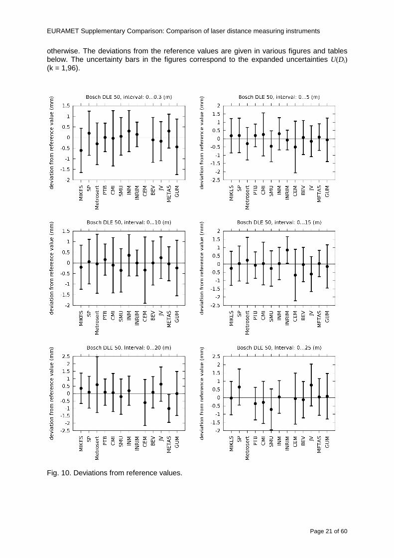
EURAMET Supplementary Comparison Comparison of laser distance measuring instruments
Page 22 of 60
Fig 10 Deviations from reference values (continued)
EURAMET Supplementary Comparison Comparison of laser distance measuring instruments
Page 23 of 60
Fig 10 Deviations from reference values (continued)
EURAMET Supplementary Comparison Comparison of laser distance measuring instruments
Page 24 of 60
Fig 10 Deviations from reference values (continued)
EURAMET Supplementary Comparison Comparison of laser distance measuring instruments
Page 25 of 60
Fig 10 Deviations from reference values (continued)
EURAMET Supplementary Comparison Comparison of laser distance measuring instruments
Page 26 of 60
Fig 10 Deviations from reference values (continued)
EURAMET Supplementary Comparison Comparison of laser distance measuring instruments
Page 27 of 60
Fig 10 Deviations from reference values (continued)
EURAMET Supplementary Comparison Comparison of laser distance measuring instruments
Page 28 of 60
Fig 10 Deviations from reference values (continued)
EU
RA
ME
T S
upplementary C
omparison C
omparison of laser distance m
easuring instruments
P
age 29 of 60
Table 8 Deviations from the reference value (given at the top of the table) and expanded uncertainties (k=196) of such deviations for BOSCH DLE 50
Table 9 Deviations from the reference value (given at the top of the table) and expanded uncertainties (k=196) of such deviations for BOSCH GLM 150
EU
RA
ME
T S
upplementary C
omparison C
omparison of laser distance m
easuring instruments
P
age 30 of 60
Table 10 Deviations from the reference value (given at the top of the table) and expanded uncertainties (k=196) of such deviations for Leica DISTO D3a BT
Table 11 Deviations from the reference value (given at the top of the table) and expanded uncertainties (k=196) of such deviations for Leica DISTO D8
EURAMET Supplementary Comparison Comparison of laser distance measuring instruments
Page 31 of 60
11 En Tables Results with En gt 1 are marked with red color in Tables below En values are calculated by Di U(Di) with Di and U(Di) as given on page 19
Table 12 BOSCH DLE50
Lab Distance (mm) 300 5000 10000 15000 20000 25000 30000 35000 40000 45000 50000
MIKES -058 017 -019 -023 035 -002 -096 SP 020 019 006 005 009 059 064 037 028 097 001
Metrosert -030 -031 -003 018 032 PTB 001 029 022 -006 011 -036 001 -023 -075 -083 001 GUM -033 -005 -018 -009 000 006 017 005 -026 -028 019 CMI -003 020 -009 004 005 -022 028 SMU 006 -049 -034 -023 -017 -057 051 039 021 INM 032 031 037 006 020 005 -079 -119 -272 -260 -269
INRIM 025 -013 000 096 CEM -032 -022 -041 -039 -004 -038 080 001 -094 -047 BEV -010 007 000 -001 008 -011 037 013 -001 008 -001 JV -019 -016 025 -055 055 060 068 163 122 060 089
METAS 038 012 -005 007 -107 004 -024 002 -070 037 -052
Table 13 BOSCH GLM150
Lab Distance (mm) 300 5000 10000 15000 20000 25000 30000 35000 40000 45000 50000
MIKES 005 -002 019 018 027 019 062 SP 003 068 029 023 051 008 015 016 -005 -001 038
Metrosert -061 -011 -022 -021 -003 PTB 066 074 062 062 034 053 047 048 047 091 064 GUM -007 -014 007 -018 000 023 020 033 014 032 038 CMI -057 -032 -030 -064 -050 -047 000 SMU 023 -024 -060 012 062 001 -003 050 047 INM -022 017 -003 002 -003 054 005 -006 016 -022 -055
INRIM 079 -052 -050 -026 -034 -042 CEM 002 002 -034 -020 -029 -077 -077 -077 -074 -104 BEV -004 -002 -007 010 -042 -042 -029 -011 -028 -022 -030 JV 003 015 040 011 -020 021 -029 -005 028 036 058
METAS -047 -020 005 002 -012 -033 -054 -065 -053 -082 -040
Table 14 Leica DISTO D3a BT
Lab Distance (mm) 300 5000 10000 15000 20000 25000 30000 35000 40000 45000 50000
MIKES 008 094 050 -011 028 051 045 SP 033 038 056 017 053 065 076 051 017 071 011
Metrosert -060 -004 -037 -014 -002 PTB 067 000 070 030 089 062 061 081 124 050 072 GUM 023 019 035 008 038 053 029 058 070 064 063 CMI -001 -004 027 -011 011 034 -033 SMU 002 -013 -019 007 -013 -055 045 -013 -042 INM 002 -039 -058 001 002 -045 -080 -051 -102 -101 -378
INRIM 070 -020 063 101 CEM -028 -004 -004 -064 003 -002 -050 -022 -093 -160 BEV -032 -019 -019 004 -011 -037 -017 -002 -025 005 012 JV 027 019 027 042 046 039 043 048 072 115 024
METAS -091 -008 -102 -098 -111 -103 -092 -080 -073 -108 -043
EURAMET Supplementary Comparison Comparison of laser distance measuring instruments
Page 32 of 60
Table 15 Leica DISTO D8
Lab Distance (mm) 300 5000 10000 15000 20000 25000 30000 35000 40000 45000 50000
MIKES 025 013 058 036 038 061 022 SP 057 026 040 016 013 016 025 017 -007 -019 007
Metrosert -021 006 -016 -043 -019 PTB 040 011 035 -005 -011 -002 -004 035 047 022 069 GUM -028 005 -025 031 039 -015 029 048 041 052 072 CMI -104 -026 -072 -057 -006 -017 -015 SMU -067 -017 -051 -026 -016 -054 -004 -001 -016 INM 021 -014 009 003 -017 -031 -010 007 029 036 041
INRIM 076 -024 -004 047 -007 083 CEM 004 -009 002 -033 -051 -059 -097 -077 -116 -134 BEV -057 -014 -051 -093 -024 -027 -021 -036 -038 -028 -041 JV 014 031 047 030 044 043 035 056 093 108 030
METAS 035 007 026 038 -013 -024 -011 -048 -089 -074 -066
12 Conclusions It was the first comparison of EDMs For most of the laboratories it was an important opportunity to validate their measurement instrumentation and procedure It allowed to become aware of potential problems and to take corrective actions in changing the procedure
For the evaluation of the reference value the weighted mean approach has been chosen although the consistency check according to procedure A of Ref [1] failed in many cases A more complicated procedure for the evaluation of the reference value was proposed which slightly changes the uncertainty of the reference value
In total there were 23 En values larger than 1 This represents 47 of the full set of 482 results It is less than the 5 of possible values being out of the expanded uncertainty of the reference value for k=2
The uncertainty of the results mainly comes from the uncertainty of the reproducibility It is difficult to distinguish between Labrsquos calibration and measurement capability
The comparison shows a global compliance with declared CMCs independently of whether some participant can have a high percentage of values not compliant with its CMC due to the influence of the artifact and the estimation of its uncertainty
13 References [1] M G Cox The evaluation of key comparison data Metrologia 39 589 ndash 595 (2002)
[2] R Thalmann EUROMET 677 ndash Steel Tape Measures Final report (2004)
[3] F Pollinger personal communication
EURAMET Supplementary Comparison Comparison of laser distance measuring instruments
Page 33 of 60
Appendix 1 Description of the measurement equipmen t as reported by the laboratories
A11 MIKES Finland
Short description of measurement bench
MIKES interferometric bench is situated in an underground laboratory with air temperature and humidity control Typically air temperature is 20 plusmn 01 degC and humidity 45 plusmn 2 RH The linear guide on the top of the concrete beam comprises two parallel round shafts with adjustable fixtures every 1 m A carriage with ball bush bearings is moved along the rail and location of it is measured with reference interferometer HP-5529A Temperature of air is measured with 6 pt100 sensors and Keithley 2010 multimetre with 4-wire resistance mode Air pressure and humidity are measured with Vaisala PTU200 Updated Edleacuten equation by Boumlnsch amp Potulski is used for calculation of refractive index of air
For EDM calibration on the other end than laser interferometer is a fixed reference plate which is adjusted perpendicular to the laser beam Next to the reference plate is an adjustable base for EDM instrument with which it can be adjusted to point parallel and coincident with measurement arm of the interferometer A target plate adjusted perpendicular to laser beam is fixed to the carriage The calibration followed Abbe principle with some millimetre uncertainty in offset adjustment
First reference interferometer is set to zero when the target plate and reference plate are in contact then EDM is positioned and adjusted in its base The rear surface of the EDM is also slightly pressed against reference surface behind it Then the readings from both instruments are collected at selected locations For this calibration there is no fine adjustment of the target position so there are typically deviations of up to few millimetres from nominal locations Results are averages of 3-4 measurements
Additional remarks
The CMC entry MIKES has for EDM calibrations is based on calibration of length scales of high quality total stations and laser trackers This type of EDMs used in this comparison are not accurate enough for truly testing of MIKES calibration measurement capability
EURAMET Supplementary Comparison Comparison of laser distance measuring instruments
Page 34 of 60
A12 SP Sweden
Short description of measurement bench
The bench consists of a simple aluminium Uminusshaped profile with polished steel pins acting as supports for the tape The bench is a little over 50 m long and works as support for the reference tape and the calibrated EDMs simultaneously
Length measurement instrument
Comparison with reference steel tape
Temperature measurement system number and location of sensors
The tape temperature is continuously registered in 6 points equally distributed along the bench The air temperature is monitored during the measurements but not used for corrections
Additional remarks
The EDM support is placed approximately 2 cm vertically above the tape No visual aid is used
EURAMET Supplementary Comparison Comparison of laser distance measuring instruments
Page 35 of 60
A13 AS Metrosert Estonia
Short description of measurement bench
The 21-m bench is located in the designated corridor-like laboratory room The lab is air-conditioned and the stability of temperature is typically plusmn05 ordmC There are three humidity and temperature sensors in room for stability and gradient monitoring
Two stainless steel rails running in parallel are made of 3-m long rods The rails lay without fixed attachment on metal supports which are mounted on concrete base The base rests on pillars made of bricks
Length measurement instrument
Laser-interferometer system Renishaw ML10 was used as length measurement instrument
Laser interferometer gets temperature humidity and pressure data from itrsquos own measurement system EC10
Additional remarks
Due to the length of the bench only measurements up to 20 m could be made Five measurement series were made with each EDM
EURAMET Supplementary Comparison Comparison of laser distance measuring instruments
Page 36 of 60
A14 PTB Germany
Short description of measurement bench
The measurements were performed on the 50 m geodetic base of the PTB The comparator consists of a 50 m rail The laboratory is equipped with a network of 21 temperature sensors spaced by 25 m along the bench As depicted in fig 1 the EDM is mounted at one end of the comparator the reflector is fixed vertically on the carriage A large retroreflector is mounted approximately 150 mm below the EDM reflector on the carriage reflecting the beam of the reference interferometer The deviation of the length due to tilting carriage (Abbe error) has been investigated along the bench by comparison of two interferometers It remains smaller than 100 microm The distance of the first position of 300 mm with respect to the back side of the EDM is determined by a gauge block of 300 mm length and a thickness of 10 mm This procedure is depicted for one of the comparison standards in figure 2
For the calibration the desired positions are programmed After the carriage reaches a measurement position the operator waits for another 30 s for the carriage to settle In control experiments the remaining movement between positioning and measurement remained smaller than 2 microm The operator then activates the measurement of the EDM reads the indicated position and writes it down The procedure is repeated for twelve times at every position the mean of the 12 measurements represents the ldquoindicated distance by the EDMrdquo All measurements of a single run at one position are performed within approximately one minute The complete measurement was repeated for four times
Length measurement instrument
The reference length is determined by a frequency-calibrated laser interferometer (Agilent 5519A) The reference interferometer is set up in Michelson geometry the signals being digitalised by a Heidenhain IK 121 card The index of refraction is determined by the external weather station of the geodetic base consisting of 21 Pt-100 temperature sensors spaced 25 m along the bench two humidity sensors (Testo 650) and two pressure sensors (Setra 370 and DPI 141) The environmental parameters are used to determine the index of refraction for the reference measurement deploying the modification of the Edleacuten equation by Boumlnsch and Potulski
EURAMET Supplementary Comparison Comparison of laser distance measuring instruments
Page 37 of 60
A15 CMI Czech Republic
Description of measurement bench
The EDMs were measured on 30 m long measuring bench equipped by laser interferometer (LI) Renishaw ML10 (pic 1 and 2) calibrated traceable to national standard of length and quantities of environmental sensors The target plate and retroreflector of the LI were fixed on a moving part of the bench and each EDM was fixed in horizontal position by clamps (pic 3) LI and EDM are placed on opposite ends of bench the Abbe offset was lt10 mm for some of them and lt50mm for all The value of LI was reset (to zero) at position corresponding to the rear of the EDM (using 3D measuring arm FARO Quantum with uncertainty about 27microm) The perpendicularities of the EDM stop as well as target plate to the beam were also checked by FARO) Each EDM was 3x replaced and aligned the measurement (reading) was repeated 6 times for each alignment and position the mean value of these 3x6 measurements is stated in tables with results The uncertainty claimed covers the statistical uncertainty of single readings Only in case of Leica D8 (the best performing EDM in this comparison) we state also the uncertainty corresponding to the mean of 6 readings in last column (this uncertainty is smaller and better illustrates our CMC)
Length measurement instrument
- Laser interferometer Renishaw - Laser 633 nm Type ML10 - Compensator EC10 - 3D measuring arm FARO Quantum - 3D measuring arm FARO Quantum
EURAMET Supplementary Comparison Comparison of laser distance measuring instruments
Page 38 of 60
A16 SMU Slovakia
Short description of measurement bench
No bench is available at the SMU the measurements are being carried out in the underground corridor of the laboratory building with length of 428 m
The 50 m steel measuring tape KINEX was used as the reference laid on the floor and pulled by the force 50 N (the same force as had been applied during its calibration at the SMU) The calibration of reference tape was done at the SMU using ULM3m Zeiss with laser interferometer Agilent 5529 B (ie per 3 m parts)
Three mercury thermometers with the resolution of 01 degC were used along the measurement path each of them laid onto the tape and located at 667 m 1990 m (instead of 20 m because of this was one of measuring points) and 333 m respectively Each of them thus corresponded approximately to one third of the measured steel tape section
Regarding the 03 m measuring point the ULM3m Zeiss length measuring machine was used with the 300 mm gauge block as the reference
Length measurement instrument
We used our own target plate being fixed perpendicularly (within uncertainty stated) to the construction equipped with nonius and the camera holder transported manually along the steel tape The second construction was fixed to the tape by such a way that zero line of the tape corresponded to the rear of EDM (within uncertainty stated)
The position of the target is read on the monitor and 20 repeated readings of the EDM data took place in each measuring point (multiples of 5 m up to 40 m)
Concerning 03 m the 300 mm gauge block was fit between the target plate and the construction with EDM The distance of the EDM rear from the target plate corresponded to the length of gauge block (within uncertainty stated)
Additional remarks
The identical measurement method was used as we use to do within our calibration service although the results reporting is different ndash we provide the regression line calculated from the measurement of irregularly distributed points and corresponding uncertainty (k = 2) in the form of [a bL] mm (ie the same coefficients for each length in the range (0 ndash 42) m)
SMU hasnrsquot got this category in CMC tables
EURAMET Supplementary Comparison Comparison of laser distance measuring instruments
Page 39 of 60
A17 INM Romania
Short description of measurement bench
Geodesic base located in the basement of the laboratory with nominal length equal to 50 m having a mobile carriage thet support both laser He-Ne retroreflector and the target of the laser distance measuring instrument in the front of geodesic base exists a support where are aligned both laser interferometer and the laser distance measuring instruments
Length measurement instrument
Laser interferometer type Hewlett Packard model 5526 A with nominal length equal to 50 m resolution 0001 mm
U = 02 microm +0510-6L
Additional remarks
During the measurements the maximum gradient of temperature was equal to 05 degC
EURAMET Supplementary Comparison Comparison of laser distance measuring instruments
Page 40 of 60
A18 INRIM Italy
Short description of measurement bench
The facility for long distance measurements is located in a corridor of the gallery devoted to dimensional metrology The structure consists in a 28 m long rail fixed to a series of pillars which rest directly on the ground released from the vibrations of floor and wall The measuring system is based on a heterodyne interferometer whose mobile arm consists of a hollow retro-reflector mounted on a structure that can run along the rail so-called carriage A photograph of the facility is presented in Fig1
The carriage is moved by a micro-step motor the motor driver receives a digital pulse and converts it into an electrical pulse to run the motor Each pulse causes a rotation of the motor shaft of one step which amounts to 11000 of a complete revolution of the shaft If the pulse frequency increases the rotation becomes continuous with a speed that is directly proportional to the pulse frequency The speed ranges between few microms up to 27 ms with a resolution of 03 microms
Since the carriage must move back and forth automatically for a distance of almost 30 m a remote control to send pulses to the motor driver was implemented It consists of two parts a radio command which allows to set some general parameters of the carriage movement such as the movement direction and mode of travel (slow or fast) and a fast command which is performed by an amplitude modulated laser beam placed at the beginning of the track oriented towards the carriage A photo detector placed above the carriage receives the modulated laser beam which is transformed into pulses to be sent to the driver of the motor The modulation of the laser beam is implemented by a LabView program that controls a digital output of the data acquisition device
Length measurement instrument
The length measurement instrument is based on a heterodyne incremental interferometer The main beam of the interferometer with frequency f1 is generated by a frequency stabilized
EURAMET Supplementary Comparison Comparison of laser distance measuring instruments
Page 41 of 60
He-Ne laser calibrated with respect to the INRIM length standard and sent to the measurement arm the second beam is a portion of the first one diffracted by an acousto-optic modulator (AOM) with frequency f2 = f1 + 80 MHz The reference detector acquires the beat note signal at 80 MHz while the measurement detector acquires a signal at 80 MHz whose phase is varied due to the displacement of the retro-reflector moving on the rail In figure 2 the optical design of the interferometer is presented
Two different measuring techniques have been implemented
1 the ldquophase measuringrdquo technique based on fringes counting with a relative uncertainty of 5middot10-7 but limited at the maximum carriage speed of 3 cms
2 the ldquoDoppler frequency measurementrdquo technique for higher carriage speed based on the measurement of the Doppler frequency shift while the carriage runs
The second technique was validated by means of the comparison with the first technique at low speed with an agreement of the order of 3middot10-6 hence the Doppler frequency method could be considered validated within 01 mm over the whole rail path with the advantage of reducing the time needed to cover long distances so it was used for the EDM comparison
In order to obtain the distance covered by the carriage according to technique 2 the Doppler frequency is measured by a commercial high-performance counter (a Pendulum CNT-90) without dead time based on time stamping then it is converted in speed and integrated over time according to the following formula
( ) ( )int minus=minus= tffn
dtn
ffdairair
λλ
2
1
2
1
where d is the distance covered by the carriage f is the frequency of the measuring signal with the carriage at rest frsquo the frequency of the measuring signal with the carriage moving λi
is the wavelength of the laser in vacuum n - air is the air refractive index and ti is the integration time The difference frsquo-f is just the Doppler frequency due to the moving carriage
The time interval measurement resolution of the instrument is 100 ps and the time base is
EURAMET Supplementary Comparison Comparison of laser distance measuring instruments
Page 42 of 60
connected to the INRIM UTC so that the measurements of the Doppler frequency and the integration time are extremely accurate The environmental parameters such as air temperature atmospheric pressure partial pressure of water were monitored during the measurement process in order to calculate the value of air refractive index according to the Edlenrsquos formula
Comparison set-up
The different technical solutions adopted for the EDMs and for the target plate positioning are discussed in this paragraph and sketched in figure 3
Fig 3 picture of the EDM and target positioning area
Target plate positioning
In order to use the provided target plate an ad-hoc mounting was manufactured at INRIM it consists in a sort of picture frame made in aluminum which slightly clamps the target folded in half and gives it the necessary stiffness to be a reproducible target The upper part of the frame is L-shaped and allows it to be fixed to the carriage structure by means of two screws The rear part of the target mounting is depicted in figure 4 The target mounting was considered necessary because of the poor stiffness and planarity of the plastic target With the aluminium frame a planarity better than 01 mm was guaranteed The target plate is placed few centimetres next to the retro-reflector and normal to the interferometer beam axis since the EDM laser should be as close and parallel as possible to the reference beam
EURAMET Supplementary Comparison Comparison of laser distance measuring instruments
Page 43 of 60
Fig 4 picture of the rear part of the target plate mounting
EDMsrsquo positioning
The EDMs are placed on a cradle-like platform which is able to adjust the inclination of the EDM along the longitudinal axis (pitch angle) The platform height allows the EDMs to be at approx the same height as the interferometer beam A crucial role was played by the stop-wall placed behind the platform since it represents the ldquozero pointrdquo for all the length measurement Hence a particular effort was devoted to align the stop-wall so that it was normal to the interferometer beam axis and parallel to the target plate
Fig 5 detail of EDMsrsquo positioning the cradle-like platform and the stop-wall are well visible
EURAMET Supplementary Comparison Comparison of laser distance measuring instruments
Page 44 of 60
Target and stop-wall alignment
In order to have the stop-wall parallel to the target plate and normal to the interferometer beam axis the following procedure has been used
1) the stop-wall and the target plate were roughly placed trying to set them parallel and normal to the rail by eye (ie within few millimeters)
2) in order to check if the target was normal to the rail one EDM was positioned on the platform the pitch and yaw angles of the EDM were adjusted by observing the position of the EDM laser spot on the target plate when the target is moved along the rail fixed position means laser beam parallel to the carriage movement Then the target was moved until the end of the rail and a thin mirror was kept in contact with it hence observing the EDM laser reflected by the mirror it was possible to adjust the target tilt acting on the screws until the laser beam is reflected back to the source
3) finally in order to check the parallelism between the stop-wall and the target a tool made by a laser pointing orthogonally to its base was used the base was leant against the stop-wall and the laser was centered on the target when the target is near then the target was moved until the end of the rail hence observing the spot of the laser on the target it was possible to adjust the stop-wall orientation
The residual misalignment errors which we were not able to eliminate were kept into account in the uncertainty budget
Measurement of the first 30 cm
Due to the geometry of our set-up it was not possible to perform the first point of measurement by means of the interferometer indeed the carriage (hence the target) is not able to go in contact with the stop-wall
Fig 6 measurement of the first 30 cm the ruler touching the stop-wall and the target and the mechanical probe (in the back) touching the carriage are visible
EURAMET Supplementary Comparison Comparison of laser distance measuring instruments
Page 45 of 60
So a ruler made of aluminum with rounded ends and nominal length equal to 30 cm was adopted to set the distance between the target plate and the stop-wall for the first point of measurement as it is shown in figure 6 The ruler whose length was measured by a CMM machine was inserted between the target and the stop-wall leaning against the latter and the carriage was carefully moved towards the stop-wall until the target lightly touched the ruler A mechanical probe that touches the carriage structure when carriage is in the ldquo30 cmrdquo position was used as a reference measurement to check the repeatability of this distance after each measurement set
Fig 7 detail of the mechanical probe touching the carriage
Environmental parameters
The environmental parameters such as air temperature atmospheric pressure and humidity were monitored during the whole measurement process in order to calculate the value of air refractive index according to the Edlenrsquos formula
Among these parameters the temperature distribution along the mobile arm of the interferometer was our main concern mainly for two reasons
1 the temperature control of the gallery was not perfectly working during the measurement period so temperature drifts had to be monitored
2 longitudinal temperature gradients due to non uniform heating and to the presence of electronic instruments were pretty high
To the purpose 14 thermometers were uniformly dislocated along the rail and automatically recorded for all the measurement period Both temporal drifts and gradients along the path have been taken in account in the uncertainty budget In any case maximum temperature differences along the rail are within 1 degC In fig 8 an extract from the acquisition file is shown
Unfortunately the air conditioning system did not work well during the measurement campaign hence the measurements were performed at a mean temperature of 209 degC
EURAMET Supplementary Comparison Comparison of laser distance measuring instruments
Page 46 of 60
Fig 8 each curve represents the temperature distribution along the rail during the measurements campaign
Carriage waving
Since the rail is not perfectly straight and the measurement laser is not coincident with the measurement beam the Abbegrave error due to waving of the target must be considered A quantitative measurement and a qualitative measurement were carried out With an electronic level placed on the carriage the straightness on the vertical plane has been mapped with a half meter resolution (the data are reported in fig 9) With a laser placed on the carriage the horizontal and vertical waving are qualitatively compared by looking at the movements of the light spot on a target fixed to the rail end As a conclusion the horizontal and vertical waving are comparable in magnitude and the peak to peak error is of the order of 300 arcseconds
Fig 9 vertical waving of the target measured by an electronic level placed on the carriage
EURAMET Supplementary Comparison Comparison of laser distance measuring instruments
Page 47 of 60
Measurement procedure
The measurements were carried out according to the following procedure
The target was set in the starting position with the procedure described above
In sequence the four EDMs are positioned on the base the horizontal and vertical tilt are adjusted and the distance measurement is recorded An additional fifth EDM (Bosh DLE 150 property of INRiM) was included in the measurement sequence Each EDM is placed on the base and gently pushed against the reference wall in such a way that the measurement laser beam starting point is the same for all EDMs Than the horizontal and vertical angles were adjusted in order to hit the central point of the target indicated with two black marks (see pictures 3 and 6) with ldquovisualrdquo alignment The measurement button is then pressed several times (typically 5) and the average reading is recorded Typical dispersion between readings is within few last digit units In case the dispersion between readings is too large the anomaly is recorded
The carriage was then moved in the next position (about 5 m) and the measurement sequence was repeated for the 5 EDMs The operation is repeated up to 25 m The 25 m measurement is than repeated again as well as all the points till the first one so that each point is measured twice each set Since the carriage movement is ldquoopen looprdquo the positioning of the carriage was not exactly in the nominal 5 m intervals For each positioning the incremental displacement is measured by the interferometer in the Doppler mode Finally the measured values were averaged in order to give a single value for each nominal position
At the end of the measurement set when the carriage is at the 30 cm position again the sum of the interferometric measurements should be very close to zero The residual value is compared with the difference between the first and the final measurements of the mechanical probe The difference must be within the uncertainty of the Doppler technique otherwise some error occurred in the measurement set that must be repeated
At the end of the session 10 complete sets of measurements recorded from the 20th to the 30th of January 2012 have been considered for this report
Additional remarks
Effect of laser pointing
During a preliminary set of measurements we noticed a strong and unexpected dependence of the measurement result on the position of the laser spot on the target Indeed since no particular instructions were given about the relative position of the laser spot on target position (except to exclude the central joint between the two halves) we decided to work relatively close to the right side of the target -closer to the interferometer beam- in order to reduce the Abbegrave error We noticed very large errors at large distances in particular of the Leica DISTO D3a (see figure 10)
EURAMET Supplementary Comparison Comparison of laser distance measuring instruments
Page 48 of 60
Fig 10 errors of each EDM In a preliminary set of measurements
We also noticed that this error was strongly dependent on the position of the spot on the target For this reason we carried out a set of measurements at the maximum length in different positions of the target from one edge to the other according to figure 11 The results are reported in table V
EDM A B C D E
Leica D3a -4 +1 0 +24 +43
+2 0 +42 +40
-1 0 +38
Leica D8 0 0 0 2 +7
0 +12 +23
table V deviations (in mm) from the length measured at point C aiming the laser spot at different positions of the target (notations as in figure 11)
We tried to find an explanation to this effect in the shape of the laser spot if the spot was
EURAMET Supplementary Comparison Comparison of laser distance measuring instruments
Page 49 of 60
particularly defocused or had high diffraction some of the energy could fall out of the target and affect the measurement result In fact the images of the spots (shown in fig 12) do not support this hypothesis Finally we decided to use the center of the (half) target for the comparison
Changing the target
In order to investigate the influence of the target on the measurements a cardboard foil (400 x 400) mm was fixed to the target mounting and a complete set of measurements was performed The results reported in figure 13 and 14 do not show any evidence of a possible dependency of the EDM measurement on the target kind
EURAMET Supplementary Comparison Comparison of laser distance measuring instruments
Page 50 of 60
Measurement at 50 m
Although we are not able to perform traceable length measurements beyond 28 m we wanted to get a sense of EDMs behaviour at longer distances So a target (represented by a rack side wall) was placed at approximately 50 m one after the other the EDMrsquos were positioned on the base and pointed towards the target The measurements were repeated then the target was replaced by the target used for the comparison and a third set of measurements were performed To our great surprise all the EDMrsquos were in good agreement (within 2 or 3 mm for each set of measurement) even those which showed errors of the order of five to ten millimeters at 25 m namely BOSCH DLE 50 and LEICA DISTO D3a Therefore each set of measurements was averaged and the deviations from the mean value are reported in figure 15
EURAMET Supplementary Comparison Comparison of laser distance measuring instruments
Page 51 of 60
Fig 15 Deviations from average value of the measurements At 50 m
EURAMET Supplementary Comparison Comparison of laser distance measuring instruments
Page 52 of 60
A19 CEM Spain
Short description of the measurement bench
To make the measurements of EDMs we have used a reference line made of adjustable supports fixed on a wall of the laboratory Each support is nominally separated five metres from the previous one so we can generate reference lengths up to fifty metres with a pitch of five metres The supports are designed to accommodate both targets and handheld EDMs Distances between supports were measured by using a total station traced to national standards The relative angles of the bases have been measured and corrected
Fig 1 - View of three consecutive supports of the 50 m baseline (left) Lab technician situating an EDM on the first support of the baseline (right)
Length measurement instrument
The baseline was calibrated by using a total station Leica TDA5005 with spherical reflector the calibration uncertainty being 02 mm for k = 2
The target is provided by the comparison The quality of the target was judged as not good due to geometrical constructive errors and the lack of rigidity and stability We measured the flatness of the target surface the distance edge-surface and the angle between them by using a 3D coordinate measuring machine The results of flatness and angle were included in the uncertainty budget and the distance EDM-target was corrected for each EDM due to each beam impinged on a different point of the target
We were not able to measure the distance 0 to 03 m because the baseline pitch is 5 meters and although we are able to measure shorter values in a different facility the target was not appropriate for our bench
EURAMET Supplementary Comparison Comparison of laser distance measuring instruments
Page 53 of 60
Fig 2 - View of an EDM on the first support of the baseline (left) A closer look showing the support adjustments and the origin plate (right)
Fig 3 - View of the comparison target on one of the supports of the baseline (left) A closer look showing the target edge against the support rigid reference (right)
Measurement method
The measurements were carried out by comparison against the known values of the calibrated baseline (metallic references on supports)
Environmental conditions were maintained within the following limits
- Temperature 20 ordmC plusmn 05 ordmC
- Humidity 45 plusmn 10
Each laser distance measuring instrument was placed at the first support of the base and aligned so that the laser beam was perpendicular to the target as indicated by the comparison protocol
For each measurement we took the average of thirty measurements It permitted us to evaluate the repeatability of the instrument
EURAMET Supplementary Comparison Comparison of laser distance measuring instruments
Page 54 of 60
A110 BEV Austria
Short description of the measurement bench
Fig 1 Carriage of tape bench View from the laser interferometer side Retroreflector mounted on the vertical plate the EDM target is mounted on the backside
Fig 2 Support for the DUT Adjustable with 2 translational and 2 rotational degrees of freedom respectively
Fig 3 Setting of the 300 mm starting position Note the rough-and-ready mounted target plate
Fig 4 Laser interferometer side of the bench The DUT is 50 m away on the other side
EURAMET Supplementary Comparison Comparison of laser distance measuring instruments
Page 55 of 60
Measurement procedure 1 The EDM is positioned with the help of a 4-axis positioning stage so that its laser beam is
coaxial with the measurement direction of the laser interferometer (in head on configuration)
2 The EDM is removed from its support The bench carriage is positioned so that the distance of the target plate from the EDM back support is 300 mm A length bar with spherical faces is used for this adjustment The laser interferometer is preset to 300 mm and the EDM is put back on its support
3 At each position 10 consecutive measurements are taken (repeatability) and the carriage is moved to the next position The carriage is manually moved under control of the laser interferometer until it is within plusmn30 microm at the correct position (Exception for the DLE 150 the target is not positioned at 10 m but at 10 m ndash 1 mm to make use of the higher resolution) The indicated (not the nominal) distance of the laser interferometer is recorded for the determination of the deviation
4 After reaching the 50 m position all points are measured in reverse order (bidirectional) Immediately after the last measurement the EDM is removed and the indication using the 300 mm length bar is checked (thus noting a possible drift of the setup)
5 Each instrument was measured 4 times according to this procedure on different days (reproducibility of bench and instrument)
Length measurement instrument
Agilent laser interferometer with long range option The bench was completed short time before performing these measurement So the characterisation was not complete and the respective measurement uncertainty of the laser interferometer is estimated rather high But anyway its contribution to the overall uncertainty can nearly be neglected
Additional remarks
The uncertainty originating from the DUT is the dominating uncertainty contribution Specifically the resolution of the two Bosch instruments (1 mm) and the repeatability are the largest contributions For the DLA 50 the pooled standard deviation of a reading at 50 m is larger than 2 mm Moreover the length dependence is not a simple function
All of the instruments show a significant deviation of the laser beam from the normal of the back (reference) face of the instrument The measured angles reach from 04deg (D3a) to 11deg (DLE 50) This leads depending on the outer dimensions of the instruments to a constant uncertainty contribution of 02 mm in our setup It must be noted that the reference faces are not well defined in most of the instruments
The reproducibility is quite different for the four instruments so only part of it originates from the setup For CMC claims we will use the standard uncertainty value of the most reproducible instrument (D3a) which amounts to 013 mm For an ideal instrument with a resolution of 01 mm and perfect repeatability we would thus have a constant expanded uncertainty of 053 mm up to 50 m
EURAMET Supplementary Comparison Comparison of laser distance measuring instruments
Page 56 of 60
A111 JV Norway
Short description of measurement bench
EDM under calibration and the reference system are aligned along a 50 m measurement bench with rails to carry the linear movement of a target plate for the EDM and a corner cube reflector for the reference system The distance between parallel axis of EDM and axis of the reference system is 130 mm Abbe error due to angle errors for the movement is smaller than 01 mm and is corrected for at each measurement point At long lengths an aperture is used approximately midway between the target plate and the EDM to avoid interfering stray light to the EDM
Alignment procedure
1) Alignment of reference system to the movement of the carriage (rails)
2) Alignment of the EDM to the movement of the carriage (rails)
3) Alignment of a plane mirror at the position of the target plate using back-reflection to the EDM output (normal incident of light on the mirror)
4) Take out the EDM and align the zero reference plate at the back of the EDM to the plane mirror
5) The mirror is replaced by the target plate and the target plate is aligned to the zero reference plate
6) Zero setting of the reference measurement system when target plate is at zero distance to the reference plate at the back of the EDM
7) Put the EDM back in position and realign it to the movement of the carriage (rails)
8) Zero setting of the EDM to the reference plate
Image 1) Image 2) Image 3) Image 4)
Image 1) Items 5) ndash 6) in alignment procedure
Fixture for HP linear interferometer is seen bottom right Part of Wyler instrument is seen to the left blue colour
Image 2) Items 7) and 8) in alignment procedure
Micrometer screws for angle alignment in two directions and linear translation for zero setting of the EDM Push button on the EDM is positioned at the tilting point of the angle adjustment table to maximize stability during measurement HP 5519 A laser head is seen to the right
Image 3) Ready to measure at selected distances from zero point the reference plate
Image 4) EDM spot size at 50 m
Length measurement instrument
- Hewlett Packard Dynamic Calibrator 5519 A (max range 80 m)
- Pressure air temperature humidity Vaisala
EURAMET Supplementary Comparison Comparison of laser distance measuring instruments
Page 57 of 60
- Digital high resolution angle measurement Wyler
I used our own target plate which is of the same type as enclosed in the artefact suitcase article number 766560 from Leica but with reduced size width x hight = 90 x 137 mm
The zero reference plate is of similar type and size
Before measurements batteries of EDMs were switched to new batteries Old batteries are switched back after calibration
For L gt 5 m an aperture of similar size as the target plate is used approximately midway between the EDM and the target plate
Additional remarks
Reports on EDM indicated values at each measurement point is the average value of n = 5 repetitions A linear model of the standard deviation for the repeatability of the EDM readings at different lengths is estimated using m = 20 repetitions at least 5 positions along the scale An estimate of the length dependent repeatability is made for each instrument
The expanded uncertainty U(95) is rounded up to the limiting resolution of 1 mm in the interval 10 m to 40 m for Bosch GLM 150
After the calibration we also estimated the angle error of the optical axis of the EDM to its back plane (back reference of EDM) Bosch DLE 50 26 mrad up measured at 50 m Bosch GLM 150 8 mrad to the left measured at 50 m Leica DISTO D3a 37 mrad down measured at 20 m Leica DISTO D8 2 mrad to the left and 4 mrad down (45 mrad total) measured at 20 m
The distance between parallel walls will be measured too large if the back plane is assumed to be normal to the optical axis of the EDM by ∆LL = (1cosα ndash 1) Bosch DLE 50 ∆LL = 340 ppm (∆L = 17 mm at L = 50 m) Bosch GLM 150 ∆LL = 32 ppm (∆L = 16 mm at L = 50 m) Leica DISTO D3a ∆LL = 7 ppm (∆L = 034 mm at L = 50 m) Leica DISTO D8 ∆LL = 10 ppm (∆L = 05 mm at L = 50 m)
EURAMET Supplementary Comparison Comparison of laser distance measuring instruments
Page 58 of 60
A112 METAS Switzerland
Short description of measurement bench (photo recom mended)
50 m bench with laser interferometer (see photo detailed description in Michel Degoumois Un Long laboratoire de mesure OFMETinfo Vol5 No 2 1998)
Length measurement instrument
HP 5529 B laser interferometer range 80 m
EURAMET Supplementary Comparison Comparison of laser distance measuring instruments
Page 59 of 60
A113 GUM Poland
Short description of measurement bench
The 50 m bench is situated in the corridor laboratory located in the basement and has its own air conditioning system with air temperature 20 plusmn 1 degC and humidity 50 plusmn 10 RH The measuring carriage is carried microscope with CCD camera and the optics associated with the interferometer The carriage is driven using belt-transmission and electrical engine with remote ndash controlled variable speed drive
The EDM was placed on the fixed adjustable plate on the other end than laser interferometer The target plate of the EDM was placed on the measuring carriage For each EDM 3 series of measurement were done Before the each measurement EDM was repositioned and aligned again
Length measurement instrument
1 Laser interferometer HP 5529A with long-range option laser head HP 5519A
2 Ambient measurement system number and location of sensors - 20 air temperature sensors type YSI with KEITHLEY multimeter they are placed very
close to axis of the laser beam - air pressure and humidity are measured with Vaisala barometer and
thermohigrometer - CO2 content was measured with analyzer made by Intelli Charge type SPN 4462
EURAMET Supplementary Comparison Comparison of laser distance measuring instruments
Page 60 of 60
Appendix 2 Corrections of reports
131 CEM Spain
CEM reported two errors in their report
1) Bosch GLM 150 EDM error for 35 m should be -08 mm instead of the indicated 08 mm
2) Leica DISTO D8 EDM error for 35 m should be -019 mm instead of the indicated 019 mm
Proposed corrections have been included in Tables 2 and 4 of the Final Report
132 AS Metrosert Estonia
AS Metrosert reported mixed up of all results for Bosch DLE 50 and Bosch GLM 150 The results and uncertainties sent for DLE 50 was results for GLM 150 and vice versa
Proposed corrections have been included in Tables 1 and 2 of the Final Report
133 INRIM Italy
Among the data reported from INRIM some anomalies were found in the measurements of BOSCH DLE 50 and LEICA DISTO D3a at distances of 20 and 25 m
After preliminary discussion on Draft A it was understood that those anomalies could be explained as a sensitivity of said instruments to the laser light that once diffused by the target is reflected by surfaces parallel to the measurement axis and detected together with the wanted signal The superimposition of the two signals can cause a ldquopullingrdquo effect leading to an overestimation of the distance being the reflected path always longer than the direct one Indeed in the INRIMrsquos set-up the target was mounted pretty close to the flat rail used for the carriage movement being likely responsible for unwanted reflections that disturbed the measurements
Since the errors reported in INRIMrsquos measurements can be ascribed to a defect of BOSCH DLE 50 and LEICA DISTO D3a andor to a lack of description of the working conditions of said instruments INRIM asked to eliminate its measurement points at 20 and 25 m of said instruments from the comparison
Proposed corrections have been included in Tables 1 and 3 of the Final Report
134 JV Norway
Justervesenet has changed the procedure and introduced two apertures instead of only one aperture (iris) which was positioned at half distance between EDM and target The reason is that the reference beam also has an aperture and it is positioned right below the beam from the EDM (130 mm distance between axes) Some diffusively reflected stray light from the EDM target might enter the aperture for the reference beam reflect at the measurement table and reach the detector of the EDM In our calibration set-up we have only seen problems at L gt 30 m We will position the first aperture at ca 5 m from the EDM and then the second aperture at ca 25 m This combination of two apertures will effectively eliminate interference of stray light from the measurement table to the EDM detector for all lengths up to 50 m
Justervesenet also increases the uncertainty component regarding repeatability reproducibility so that the expanded uncertainty increases from 14 mm to 15 mm
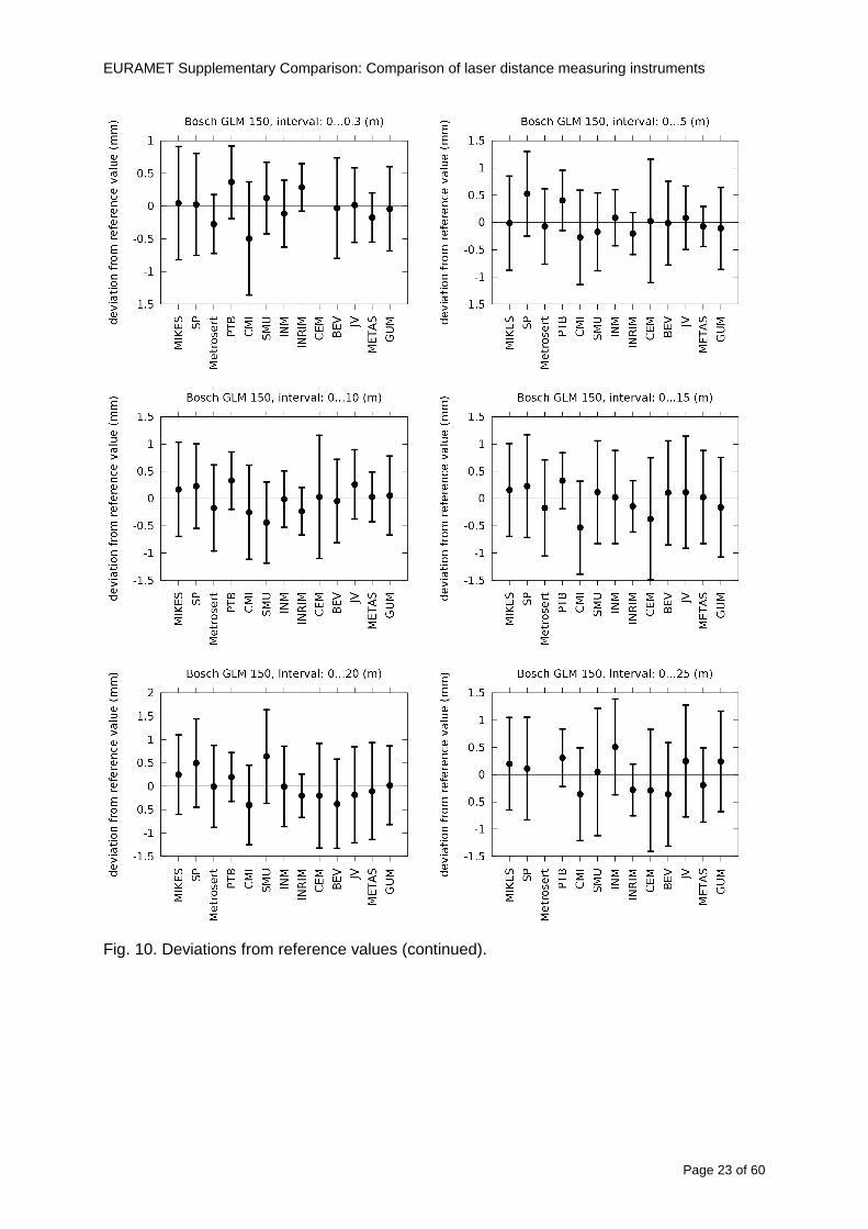
EURAMET Supplementary Comparison Comparison of laser distance measuring instruments
Page 23 of 60
Fig 10 Deviations from reference values (continued)
EURAMET Supplementary Comparison Comparison of laser distance measuring instruments
Page 24 of 60
Fig 10 Deviations from reference values (continued)
EURAMET Supplementary Comparison Comparison of laser distance measuring instruments
Page 25 of 60
Fig 10 Deviations from reference values (continued)
EURAMET Supplementary Comparison Comparison of laser distance measuring instruments
Page 26 of 60
Fig 10 Deviations from reference values (continued)
EURAMET Supplementary Comparison Comparison of laser distance measuring instruments
Page 27 of 60
Fig 10 Deviations from reference values (continued)
EURAMET Supplementary Comparison Comparison of laser distance measuring instruments
Page 28 of 60
Fig 10 Deviations from reference values (continued)
EU
RA
ME
T S
upplementary C
omparison C
omparison of laser distance m
easuring instruments
P
age 29 of 60
Table 8 Deviations from the reference value (given at the top of the table) and expanded uncertainties (k=196) of such deviations for BOSCH DLE 50
Table 9 Deviations from the reference value (given at the top of the table) and expanded uncertainties (k=196) of such deviations for BOSCH GLM 150
EU
RA
ME
T S
upplementary C
omparison C
omparison of laser distance m
easuring instruments
P
age 30 of 60
Table 10 Deviations from the reference value (given at the top of the table) and expanded uncertainties (k=196) of such deviations for Leica DISTO D3a BT
Table 11 Deviations from the reference value (given at the top of the table) and expanded uncertainties (k=196) of such deviations for Leica DISTO D8
EURAMET Supplementary Comparison Comparison of laser distance measuring instruments
Page 31 of 60
11 En Tables Results with En gt 1 are marked with red color in Tables below En values are calculated by Di U(Di) with Di and U(Di) as given on page 19
Table 12 BOSCH DLE50
Lab Distance (mm) 300 5000 10000 15000 20000 25000 30000 35000 40000 45000 50000
MIKES -058 017 -019 -023 035 -002 -096 SP 020 019 006 005 009 059 064 037 028 097 001
Metrosert -030 -031 -003 018 032 PTB 001 029 022 -006 011 -036 001 -023 -075 -083 001 GUM -033 -005 -018 -009 000 006 017 005 -026 -028 019 CMI -003 020 -009 004 005 -022 028 SMU 006 -049 -034 -023 -017 -057 051 039 021 INM 032 031 037 006 020 005 -079 -119 -272 -260 -269
INRIM 025 -013 000 096 CEM -032 -022 -041 -039 -004 -038 080 001 -094 -047 BEV -010 007 000 -001 008 -011 037 013 -001 008 -001 JV -019 -016 025 -055 055 060 068 163 122 060 089
METAS 038 012 -005 007 -107 004 -024 002 -070 037 -052
Table 13 BOSCH GLM150
Lab Distance (mm) 300 5000 10000 15000 20000 25000 30000 35000 40000 45000 50000
MIKES 005 -002 019 018 027 019 062 SP 003 068 029 023 051 008 015 016 -005 -001 038
Metrosert -061 -011 -022 -021 -003 PTB 066 074 062 062 034 053 047 048 047 091 064 GUM -007 -014 007 -018 000 023 020 033 014 032 038 CMI -057 -032 -030 -064 -050 -047 000 SMU 023 -024 -060 012 062 001 -003 050 047 INM -022 017 -003 002 -003 054 005 -006 016 -022 -055
INRIM 079 -052 -050 -026 -034 -042 CEM 002 002 -034 -020 -029 -077 -077 -077 -074 -104 BEV -004 -002 -007 010 -042 -042 -029 -011 -028 -022 -030 JV 003 015 040 011 -020 021 -029 -005 028 036 058
METAS -047 -020 005 002 -012 -033 -054 -065 -053 -082 -040
Table 14 Leica DISTO D3a BT
Lab Distance (mm) 300 5000 10000 15000 20000 25000 30000 35000 40000 45000 50000
MIKES 008 094 050 -011 028 051 045 SP 033 038 056 017 053 065 076 051 017 071 011
Metrosert -060 -004 -037 -014 -002 PTB 067 000 070 030 089 062 061 081 124 050 072 GUM 023 019 035 008 038 053 029 058 070 064 063 CMI -001 -004 027 -011 011 034 -033 SMU 002 -013 -019 007 -013 -055 045 -013 -042 INM 002 -039 -058 001 002 -045 -080 -051 -102 -101 -378
INRIM 070 -020 063 101 CEM -028 -004 -004 -064 003 -002 -050 -022 -093 -160 BEV -032 -019 -019 004 -011 -037 -017 -002 -025 005 012 JV 027 019 027 042 046 039 043 048 072 115 024
METAS -091 -008 -102 -098 -111 -103 -092 -080 -073 -108 -043
EURAMET Supplementary Comparison Comparison of laser distance measuring instruments
Page 32 of 60
Table 15 Leica DISTO D8
Lab Distance (mm) 300 5000 10000 15000 20000 25000 30000 35000 40000 45000 50000
MIKES 025 013 058 036 038 061 022 SP 057 026 040 016 013 016 025 017 -007 -019 007
Metrosert -021 006 -016 -043 -019 PTB 040 011 035 -005 -011 -002 -004 035 047 022 069 GUM -028 005 -025 031 039 -015 029 048 041 052 072 CMI -104 -026 -072 -057 -006 -017 -015 SMU -067 -017 -051 -026 -016 -054 -004 -001 -016 INM 021 -014 009 003 -017 -031 -010 007 029 036 041
INRIM 076 -024 -004 047 -007 083 CEM 004 -009 002 -033 -051 -059 -097 -077 -116 -134 BEV -057 -014 -051 -093 -024 -027 -021 -036 -038 -028 -041 JV 014 031 047 030 044 043 035 056 093 108 030
METAS 035 007 026 038 -013 -024 -011 -048 -089 -074 -066
12 Conclusions It was the first comparison of EDMs For most of the laboratories it was an important opportunity to validate their measurement instrumentation and procedure It allowed to become aware of potential problems and to take corrective actions in changing the procedure
For the evaluation of the reference value the weighted mean approach has been chosen although the consistency check according to procedure A of Ref [1] failed in many cases A more complicated procedure for the evaluation of the reference value was proposed which slightly changes the uncertainty of the reference value
In total there were 23 En values larger than 1 This represents 47 of the full set of 482 results It is less than the 5 of possible values being out of the expanded uncertainty of the reference value for k=2
The uncertainty of the results mainly comes from the uncertainty of the reproducibility It is difficult to distinguish between Labrsquos calibration and measurement capability
The comparison shows a global compliance with declared CMCs independently of whether some participant can have a high percentage of values not compliant with its CMC due to the influence of the artifact and the estimation of its uncertainty
13 References [1] M G Cox The evaluation of key comparison data Metrologia 39 589 ndash 595 (2002)
[2] R Thalmann EUROMET 677 ndash Steel Tape Measures Final report (2004)
[3] F Pollinger personal communication
EURAMET Supplementary Comparison Comparison of laser distance measuring instruments
Page 33 of 60
Appendix 1 Description of the measurement equipmen t as reported by the laboratories
A11 MIKES Finland
Short description of measurement bench
MIKES interferometric bench is situated in an underground laboratory with air temperature and humidity control Typically air temperature is 20 plusmn 01 degC and humidity 45 plusmn 2 RH The linear guide on the top of the concrete beam comprises two parallel round shafts with adjustable fixtures every 1 m A carriage with ball bush bearings is moved along the rail and location of it is measured with reference interferometer HP-5529A Temperature of air is measured with 6 pt100 sensors and Keithley 2010 multimetre with 4-wire resistance mode Air pressure and humidity are measured with Vaisala PTU200 Updated Edleacuten equation by Boumlnsch amp Potulski is used for calculation of refractive index of air
For EDM calibration on the other end than laser interferometer is a fixed reference plate which is adjusted perpendicular to the laser beam Next to the reference plate is an adjustable base for EDM instrument with which it can be adjusted to point parallel and coincident with measurement arm of the interferometer A target plate adjusted perpendicular to laser beam is fixed to the carriage The calibration followed Abbe principle with some millimetre uncertainty in offset adjustment
First reference interferometer is set to zero when the target plate and reference plate are in contact then EDM is positioned and adjusted in its base The rear surface of the EDM is also slightly pressed against reference surface behind it Then the readings from both instruments are collected at selected locations For this calibration there is no fine adjustment of the target position so there are typically deviations of up to few millimetres from nominal locations Results are averages of 3-4 measurements
Additional remarks
The CMC entry MIKES has for EDM calibrations is based on calibration of length scales of high quality total stations and laser trackers This type of EDMs used in this comparison are not accurate enough for truly testing of MIKES calibration measurement capability
EURAMET Supplementary Comparison Comparison of laser distance measuring instruments
Page 34 of 60
A12 SP Sweden
Short description of measurement bench
The bench consists of a simple aluminium Uminusshaped profile with polished steel pins acting as supports for the tape The bench is a little over 50 m long and works as support for the reference tape and the calibrated EDMs simultaneously
Length measurement instrument
Comparison with reference steel tape
Temperature measurement system number and location of sensors
The tape temperature is continuously registered in 6 points equally distributed along the bench The air temperature is monitored during the measurements but not used for corrections
Additional remarks
The EDM support is placed approximately 2 cm vertically above the tape No visual aid is used
EURAMET Supplementary Comparison Comparison of laser distance measuring instruments
Page 35 of 60
A13 AS Metrosert Estonia
Short description of measurement bench
The 21-m bench is located in the designated corridor-like laboratory room The lab is air-conditioned and the stability of temperature is typically plusmn05 ordmC There are three humidity and temperature sensors in room for stability and gradient monitoring
Two stainless steel rails running in parallel are made of 3-m long rods The rails lay without fixed attachment on metal supports which are mounted on concrete base The base rests on pillars made of bricks
Length measurement instrument
Laser-interferometer system Renishaw ML10 was used as length measurement instrument
Laser interferometer gets temperature humidity and pressure data from itrsquos own measurement system EC10
Additional remarks
Due to the length of the bench only measurements up to 20 m could be made Five measurement series were made with each EDM
EURAMET Supplementary Comparison Comparison of laser distance measuring instruments
Page 36 of 60
A14 PTB Germany
Short description of measurement bench
The measurements were performed on the 50 m geodetic base of the PTB The comparator consists of a 50 m rail The laboratory is equipped with a network of 21 temperature sensors spaced by 25 m along the bench As depicted in fig 1 the EDM is mounted at one end of the comparator the reflector is fixed vertically on the carriage A large retroreflector is mounted approximately 150 mm below the EDM reflector on the carriage reflecting the beam of the reference interferometer The deviation of the length due to tilting carriage (Abbe error) has been investigated along the bench by comparison of two interferometers It remains smaller than 100 microm The distance of the first position of 300 mm with respect to the back side of the EDM is determined by a gauge block of 300 mm length and a thickness of 10 mm This procedure is depicted for one of the comparison standards in figure 2
For the calibration the desired positions are programmed After the carriage reaches a measurement position the operator waits for another 30 s for the carriage to settle In control experiments the remaining movement between positioning and measurement remained smaller than 2 microm The operator then activates the measurement of the EDM reads the indicated position and writes it down The procedure is repeated for twelve times at every position the mean of the 12 measurements represents the ldquoindicated distance by the EDMrdquo All measurements of a single run at one position are performed within approximately one minute The complete measurement was repeated for four times
Length measurement instrument
The reference length is determined by a frequency-calibrated laser interferometer (Agilent 5519A) The reference interferometer is set up in Michelson geometry the signals being digitalised by a Heidenhain IK 121 card The index of refraction is determined by the external weather station of the geodetic base consisting of 21 Pt-100 temperature sensors spaced 25 m along the bench two humidity sensors (Testo 650) and two pressure sensors (Setra 370 and DPI 141) The environmental parameters are used to determine the index of refraction for the reference measurement deploying the modification of the Edleacuten equation by Boumlnsch and Potulski
EURAMET Supplementary Comparison Comparison of laser distance measuring instruments
Page 37 of 60
A15 CMI Czech Republic
Description of measurement bench
The EDMs were measured on 30 m long measuring bench equipped by laser interferometer (LI) Renishaw ML10 (pic 1 and 2) calibrated traceable to national standard of length and quantities of environmental sensors The target plate and retroreflector of the LI were fixed on a moving part of the bench and each EDM was fixed in horizontal position by clamps (pic 3) LI and EDM are placed on opposite ends of bench the Abbe offset was lt10 mm for some of them and lt50mm for all The value of LI was reset (to zero) at position corresponding to the rear of the EDM (using 3D measuring arm FARO Quantum with uncertainty about 27microm) The perpendicularities of the EDM stop as well as target plate to the beam were also checked by FARO) Each EDM was 3x replaced and aligned the measurement (reading) was repeated 6 times for each alignment and position the mean value of these 3x6 measurements is stated in tables with results The uncertainty claimed covers the statistical uncertainty of single readings Only in case of Leica D8 (the best performing EDM in this comparison) we state also the uncertainty corresponding to the mean of 6 readings in last column (this uncertainty is smaller and better illustrates our CMC)
Length measurement instrument
- Laser interferometer Renishaw - Laser 633 nm Type ML10 - Compensator EC10 - 3D measuring arm FARO Quantum - 3D measuring arm FARO Quantum
EURAMET Supplementary Comparison Comparison of laser distance measuring instruments
Page 38 of 60
A16 SMU Slovakia
Short description of measurement bench
No bench is available at the SMU the measurements are being carried out in the underground corridor of the laboratory building with length of 428 m
The 50 m steel measuring tape KINEX was used as the reference laid on the floor and pulled by the force 50 N (the same force as had been applied during its calibration at the SMU) The calibration of reference tape was done at the SMU using ULM3m Zeiss with laser interferometer Agilent 5529 B (ie per 3 m parts)
Three mercury thermometers with the resolution of 01 degC were used along the measurement path each of them laid onto the tape and located at 667 m 1990 m (instead of 20 m because of this was one of measuring points) and 333 m respectively Each of them thus corresponded approximately to one third of the measured steel tape section
Regarding the 03 m measuring point the ULM3m Zeiss length measuring machine was used with the 300 mm gauge block as the reference
Length measurement instrument
We used our own target plate being fixed perpendicularly (within uncertainty stated) to the construction equipped with nonius and the camera holder transported manually along the steel tape The second construction was fixed to the tape by such a way that zero line of the tape corresponded to the rear of EDM (within uncertainty stated)
The position of the target is read on the monitor and 20 repeated readings of the EDM data took place in each measuring point (multiples of 5 m up to 40 m)
Concerning 03 m the 300 mm gauge block was fit between the target plate and the construction with EDM The distance of the EDM rear from the target plate corresponded to the length of gauge block (within uncertainty stated)
Additional remarks
The identical measurement method was used as we use to do within our calibration service although the results reporting is different ndash we provide the regression line calculated from the measurement of irregularly distributed points and corresponding uncertainty (k = 2) in the form of [a bL] mm (ie the same coefficients for each length in the range (0 ndash 42) m)
SMU hasnrsquot got this category in CMC tables
EURAMET Supplementary Comparison Comparison of laser distance measuring instruments
Page 39 of 60
A17 INM Romania
Short description of measurement bench
Geodesic base located in the basement of the laboratory with nominal length equal to 50 m having a mobile carriage thet support both laser He-Ne retroreflector and the target of the laser distance measuring instrument in the front of geodesic base exists a support where are aligned both laser interferometer and the laser distance measuring instruments
Length measurement instrument
Laser interferometer type Hewlett Packard model 5526 A with nominal length equal to 50 m resolution 0001 mm
U = 02 microm +0510-6L
Additional remarks
During the measurements the maximum gradient of temperature was equal to 05 degC
EURAMET Supplementary Comparison Comparison of laser distance measuring instruments
Page 40 of 60
A18 INRIM Italy
Short description of measurement bench
The facility for long distance measurements is located in a corridor of the gallery devoted to dimensional metrology The structure consists in a 28 m long rail fixed to a series of pillars which rest directly on the ground released from the vibrations of floor and wall The measuring system is based on a heterodyne interferometer whose mobile arm consists of a hollow retro-reflector mounted on a structure that can run along the rail so-called carriage A photograph of the facility is presented in Fig1
The carriage is moved by a micro-step motor the motor driver receives a digital pulse and converts it into an electrical pulse to run the motor Each pulse causes a rotation of the motor shaft of one step which amounts to 11000 of a complete revolution of the shaft If the pulse frequency increases the rotation becomes continuous with a speed that is directly proportional to the pulse frequency The speed ranges between few microms up to 27 ms with a resolution of 03 microms
Since the carriage must move back and forth automatically for a distance of almost 30 m a remote control to send pulses to the motor driver was implemented It consists of two parts a radio command which allows to set some general parameters of the carriage movement such as the movement direction and mode of travel (slow or fast) and a fast command which is performed by an amplitude modulated laser beam placed at the beginning of the track oriented towards the carriage A photo detector placed above the carriage receives the modulated laser beam which is transformed into pulses to be sent to the driver of the motor The modulation of the laser beam is implemented by a LabView program that controls a digital output of the data acquisition device
Length measurement instrument
The length measurement instrument is based on a heterodyne incremental interferometer The main beam of the interferometer with frequency f1 is generated by a frequency stabilized
EURAMET Supplementary Comparison Comparison of laser distance measuring instruments
Page 41 of 60
He-Ne laser calibrated with respect to the INRIM length standard and sent to the measurement arm the second beam is a portion of the first one diffracted by an acousto-optic modulator (AOM) with frequency f2 = f1 + 80 MHz The reference detector acquires the beat note signal at 80 MHz while the measurement detector acquires a signal at 80 MHz whose phase is varied due to the displacement of the retro-reflector moving on the rail In figure 2 the optical design of the interferometer is presented
Two different measuring techniques have been implemented
1 the ldquophase measuringrdquo technique based on fringes counting with a relative uncertainty of 5middot10-7 but limited at the maximum carriage speed of 3 cms
2 the ldquoDoppler frequency measurementrdquo technique for higher carriage speed based on the measurement of the Doppler frequency shift while the carriage runs
The second technique was validated by means of the comparison with the first technique at low speed with an agreement of the order of 3middot10-6 hence the Doppler frequency method could be considered validated within 01 mm over the whole rail path with the advantage of reducing the time needed to cover long distances so it was used for the EDM comparison
In order to obtain the distance covered by the carriage according to technique 2 the Doppler frequency is measured by a commercial high-performance counter (a Pendulum CNT-90) without dead time based on time stamping then it is converted in speed and integrated over time according to the following formula
( ) ( )int minus=minus= tffn
dtn
ffdairair
λλ
2
1
2
1
where d is the distance covered by the carriage f is the frequency of the measuring signal with the carriage at rest frsquo the frequency of the measuring signal with the carriage moving λi
is the wavelength of the laser in vacuum n - air is the air refractive index and ti is the integration time The difference frsquo-f is just the Doppler frequency due to the moving carriage
The time interval measurement resolution of the instrument is 100 ps and the time base is
EURAMET Supplementary Comparison Comparison of laser distance measuring instruments
Page 42 of 60
connected to the INRIM UTC so that the measurements of the Doppler frequency and the integration time are extremely accurate The environmental parameters such as air temperature atmospheric pressure partial pressure of water were monitored during the measurement process in order to calculate the value of air refractive index according to the Edlenrsquos formula
Comparison set-up
The different technical solutions adopted for the EDMs and for the target plate positioning are discussed in this paragraph and sketched in figure 3
Fig 3 picture of the EDM and target positioning area
Target plate positioning
In order to use the provided target plate an ad-hoc mounting was manufactured at INRIM it consists in a sort of picture frame made in aluminum which slightly clamps the target folded in half and gives it the necessary stiffness to be a reproducible target The upper part of the frame is L-shaped and allows it to be fixed to the carriage structure by means of two screws The rear part of the target mounting is depicted in figure 4 The target mounting was considered necessary because of the poor stiffness and planarity of the plastic target With the aluminium frame a planarity better than 01 mm was guaranteed The target plate is placed few centimetres next to the retro-reflector and normal to the interferometer beam axis since the EDM laser should be as close and parallel as possible to the reference beam
EURAMET Supplementary Comparison Comparison of laser distance measuring instruments
Page 43 of 60
Fig 4 picture of the rear part of the target plate mounting
EDMsrsquo positioning
The EDMs are placed on a cradle-like platform which is able to adjust the inclination of the EDM along the longitudinal axis (pitch angle) The platform height allows the EDMs to be at approx the same height as the interferometer beam A crucial role was played by the stop-wall placed behind the platform since it represents the ldquozero pointrdquo for all the length measurement Hence a particular effort was devoted to align the stop-wall so that it was normal to the interferometer beam axis and parallel to the target plate
Fig 5 detail of EDMsrsquo positioning the cradle-like platform and the stop-wall are well visible
EURAMET Supplementary Comparison Comparison of laser distance measuring instruments
Page 44 of 60
Target and stop-wall alignment
In order to have the stop-wall parallel to the target plate and normal to the interferometer beam axis the following procedure has been used
1) the stop-wall and the target plate were roughly placed trying to set them parallel and normal to the rail by eye (ie within few millimeters)
2) in order to check if the target was normal to the rail one EDM was positioned on the platform the pitch and yaw angles of the EDM were adjusted by observing the position of the EDM laser spot on the target plate when the target is moved along the rail fixed position means laser beam parallel to the carriage movement Then the target was moved until the end of the rail and a thin mirror was kept in contact with it hence observing the EDM laser reflected by the mirror it was possible to adjust the target tilt acting on the screws until the laser beam is reflected back to the source
3) finally in order to check the parallelism between the stop-wall and the target a tool made by a laser pointing orthogonally to its base was used the base was leant against the stop-wall and the laser was centered on the target when the target is near then the target was moved until the end of the rail hence observing the spot of the laser on the target it was possible to adjust the stop-wall orientation
The residual misalignment errors which we were not able to eliminate were kept into account in the uncertainty budget
Measurement of the first 30 cm
Due to the geometry of our set-up it was not possible to perform the first point of measurement by means of the interferometer indeed the carriage (hence the target) is not able to go in contact with the stop-wall
Fig 6 measurement of the first 30 cm the ruler touching the stop-wall and the target and the mechanical probe (in the back) touching the carriage are visible
EURAMET Supplementary Comparison Comparison of laser distance measuring instruments
Page 45 of 60
So a ruler made of aluminum with rounded ends and nominal length equal to 30 cm was adopted to set the distance between the target plate and the stop-wall for the first point of measurement as it is shown in figure 6 The ruler whose length was measured by a CMM machine was inserted between the target and the stop-wall leaning against the latter and the carriage was carefully moved towards the stop-wall until the target lightly touched the ruler A mechanical probe that touches the carriage structure when carriage is in the ldquo30 cmrdquo position was used as a reference measurement to check the repeatability of this distance after each measurement set
Fig 7 detail of the mechanical probe touching the carriage
Environmental parameters
The environmental parameters such as air temperature atmospheric pressure and humidity were monitored during the whole measurement process in order to calculate the value of air refractive index according to the Edlenrsquos formula
Among these parameters the temperature distribution along the mobile arm of the interferometer was our main concern mainly for two reasons
1 the temperature control of the gallery was not perfectly working during the measurement period so temperature drifts had to be monitored
2 longitudinal temperature gradients due to non uniform heating and to the presence of electronic instruments were pretty high
To the purpose 14 thermometers were uniformly dislocated along the rail and automatically recorded for all the measurement period Both temporal drifts and gradients along the path have been taken in account in the uncertainty budget In any case maximum temperature differences along the rail are within 1 degC In fig 8 an extract from the acquisition file is shown
Unfortunately the air conditioning system did not work well during the measurement campaign hence the measurements were performed at a mean temperature of 209 degC
EURAMET Supplementary Comparison Comparison of laser distance measuring instruments
Page 46 of 60
Fig 8 each curve represents the temperature distribution along the rail during the measurements campaign
Carriage waving
Since the rail is not perfectly straight and the measurement laser is not coincident with the measurement beam the Abbegrave error due to waving of the target must be considered A quantitative measurement and a qualitative measurement were carried out With an electronic level placed on the carriage the straightness on the vertical plane has been mapped with a half meter resolution (the data are reported in fig 9) With a laser placed on the carriage the horizontal and vertical waving are qualitatively compared by looking at the movements of the light spot on a target fixed to the rail end As a conclusion the horizontal and vertical waving are comparable in magnitude and the peak to peak error is of the order of 300 arcseconds
Fig 9 vertical waving of the target measured by an electronic level placed on the carriage
EURAMET Supplementary Comparison Comparison of laser distance measuring instruments
Page 47 of 60
Measurement procedure
The measurements were carried out according to the following procedure
The target was set in the starting position with the procedure described above
In sequence the four EDMs are positioned on the base the horizontal and vertical tilt are adjusted and the distance measurement is recorded An additional fifth EDM (Bosh DLE 150 property of INRiM) was included in the measurement sequence Each EDM is placed on the base and gently pushed against the reference wall in such a way that the measurement laser beam starting point is the same for all EDMs Than the horizontal and vertical angles were adjusted in order to hit the central point of the target indicated with two black marks (see pictures 3 and 6) with ldquovisualrdquo alignment The measurement button is then pressed several times (typically 5) and the average reading is recorded Typical dispersion between readings is within few last digit units In case the dispersion between readings is too large the anomaly is recorded
The carriage was then moved in the next position (about 5 m) and the measurement sequence was repeated for the 5 EDMs The operation is repeated up to 25 m The 25 m measurement is than repeated again as well as all the points till the first one so that each point is measured twice each set Since the carriage movement is ldquoopen looprdquo the positioning of the carriage was not exactly in the nominal 5 m intervals For each positioning the incremental displacement is measured by the interferometer in the Doppler mode Finally the measured values were averaged in order to give a single value for each nominal position
At the end of the measurement set when the carriage is at the 30 cm position again the sum of the interferometric measurements should be very close to zero The residual value is compared with the difference between the first and the final measurements of the mechanical probe The difference must be within the uncertainty of the Doppler technique otherwise some error occurred in the measurement set that must be repeated
At the end of the session 10 complete sets of measurements recorded from the 20th to the 30th of January 2012 have been considered for this report
Additional remarks
Effect of laser pointing
During a preliminary set of measurements we noticed a strong and unexpected dependence of the measurement result on the position of the laser spot on the target Indeed since no particular instructions were given about the relative position of the laser spot on target position (except to exclude the central joint between the two halves) we decided to work relatively close to the right side of the target -closer to the interferometer beam- in order to reduce the Abbegrave error We noticed very large errors at large distances in particular of the Leica DISTO D3a (see figure 10)
EURAMET Supplementary Comparison Comparison of laser distance measuring instruments
Page 48 of 60
Fig 10 errors of each EDM In a preliminary set of measurements
We also noticed that this error was strongly dependent on the position of the spot on the target For this reason we carried out a set of measurements at the maximum length in different positions of the target from one edge to the other according to figure 11 The results are reported in table V
EDM A B C D E
Leica D3a -4 +1 0 +24 +43
+2 0 +42 +40
-1 0 +38
Leica D8 0 0 0 2 +7
0 +12 +23
table V deviations (in mm) from the length measured at point C aiming the laser spot at different positions of the target (notations as in figure 11)
We tried to find an explanation to this effect in the shape of the laser spot if the spot was
EURAMET Supplementary Comparison Comparison of laser distance measuring instruments
Page 49 of 60
particularly defocused or had high diffraction some of the energy could fall out of the target and affect the measurement result In fact the images of the spots (shown in fig 12) do not support this hypothesis Finally we decided to use the center of the (half) target for the comparison
Changing the target
In order to investigate the influence of the target on the measurements a cardboard foil (400 x 400) mm was fixed to the target mounting and a complete set of measurements was performed The results reported in figure 13 and 14 do not show any evidence of a possible dependency of the EDM measurement on the target kind
EURAMET Supplementary Comparison Comparison of laser distance measuring instruments
Page 50 of 60
Measurement at 50 m
Although we are not able to perform traceable length measurements beyond 28 m we wanted to get a sense of EDMs behaviour at longer distances So a target (represented by a rack side wall) was placed at approximately 50 m one after the other the EDMrsquos were positioned on the base and pointed towards the target The measurements were repeated then the target was replaced by the target used for the comparison and a third set of measurements were performed To our great surprise all the EDMrsquos were in good agreement (within 2 or 3 mm for each set of measurement) even those which showed errors of the order of five to ten millimeters at 25 m namely BOSCH DLE 50 and LEICA DISTO D3a Therefore each set of measurements was averaged and the deviations from the mean value are reported in figure 15
EURAMET Supplementary Comparison Comparison of laser distance measuring instruments
Page 51 of 60
Fig 15 Deviations from average value of the measurements At 50 m
EURAMET Supplementary Comparison Comparison of laser distance measuring instruments
Page 52 of 60
A19 CEM Spain
Short description of the measurement bench
To make the measurements of EDMs we have used a reference line made of adjustable supports fixed on a wall of the laboratory Each support is nominally separated five metres from the previous one so we can generate reference lengths up to fifty metres with a pitch of five metres The supports are designed to accommodate both targets and handheld EDMs Distances between supports were measured by using a total station traced to national standards The relative angles of the bases have been measured and corrected
Fig 1 - View of three consecutive supports of the 50 m baseline (left) Lab technician situating an EDM on the first support of the baseline (right)
Length measurement instrument
The baseline was calibrated by using a total station Leica TDA5005 with spherical reflector the calibration uncertainty being 02 mm for k = 2
The target is provided by the comparison The quality of the target was judged as not good due to geometrical constructive errors and the lack of rigidity and stability We measured the flatness of the target surface the distance edge-surface and the angle between them by using a 3D coordinate measuring machine The results of flatness and angle were included in the uncertainty budget and the distance EDM-target was corrected for each EDM due to each beam impinged on a different point of the target
We were not able to measure the distance 0 to 03 m because the baseline pitch is 5 meters and although we are able to measure shorter values in a different facility the target was not appropriate for our bench
EURAMET Supplementary Comparison Comparison of laser distance measuring instruments
Page 53 of 60
Fig 2 - View of an EDM on the first support of the baseline (left) A closer look showing the support adjustments and the origin plate (right)
Fig 3 - View of the comparison target on one of the supports of the baseline (left) A closer look showing the target edge against the support rigid reference (right)
Measurement method
The measurements were carried out by comparison against the known values of the calibrated baseline (metallic references on supports)
Environmental conditions were maintained within the following limits
- Temperature 20 ordmC plusmn 05 ordmC
- Humidity 45 plusmn 10
Each laser distance measuring instrument was placed at the first support of the base and aligned so that the laser beam was perpendicular to the target as indicated by the comparison protocol
For each measurement we took the average of thirty measurements It permitted us to evaluate the repeatability of the instrument
EURAMET Supplementary Comparison Comparison of laser distance measuring instruments
Page 54 of 60
A110 BEV Austria
Short description of the measurement bench
Fig 1 Carriage of tape bench View from the laser interferometer side Retroreflector mounted on the vertical plate the EDM target is mounted on the backside
Fig 2 Support for the DUT Adjustable with 2 translational and 2 rotational degrees of freedom respectively
Fig 3 Setting of the 300 mm starting position Note the rough-and-ready mounted target plate
Fig 4 Laser interferometer side of the bench The DUT is 50 m away on the other side
EURAMET Supplementary Comparison Comparison of laser distance measuring instruments
Page 55 of 60
Measurement procedure 1 The EDM is positioned with the help of a 4-axis positioning stage so that its laser beam is
coaxial with the measurement direction of the laser interferometer (in head on configuration)
2 The EDM is removed from its support The bench carriage is positioned so that the distance of the target plate from the EDM back support is 300 mm A length bar with spherical faces is used for this adjustment The laser interferometer is preset to 300 mm and the EDM is put back on its support
3 At each position 10 consecutive measurements are taken (repeatability) and the carriage is moved to the next position The carriage is manually moved under control of the laser interferometer until it is within plusmn30 microm at the correct position (Exception for the DLE 150 the target is not positioned at 10 m but at 10 m ndash 1 mm to make use of the higher resolution) The indicated (not the nominal) distance of the laser interferometer is recorded for the determination of the deviation
4 After reaching the 50 m position all points are measured in reverse order (bidirectional) Immediately after the last measurement the EDM is removed and the indication using the 300 mm length bar is checked (thus noting a possible drift of the setup)
5 Each instrument was measured 4 times according to this procedure on different days (reproducibility of bench and instrument)
Length measurement instrument
Agilent laser interferometer with long range option The bench was completed short time before performing these measurement So the characterisation was not complete and the respective measurement uncertainty of the laser interferometer is estimated rather high But anyway its contribution to the overall uncertainty can nearly be neglected
Additional remarks
The uncertainty originating from the DUT is the dominating uncertainty contribution Specifically the resolution of the two Bosch instruments (1 mm) and the repeatability are the largest contributions For the DLA 50 the pooled standard deviation of a reading at 50 m is larger than 2 mm Moreover the length dependence is not a simple function
All of the instruments show a significant deviation of the laser beam from the normal of the back (reference) face of the instrument The measured angles reach from 04deg (D3a) to 11deg (DLE 50) This leads depending on the outer dimensions of the instruments to a constant uncertainty contribution of 02 mm in our setup It must be noted that the reference faces are not well defined in most of the instruments
The reproducibility is quite different for the four instruments so only part of it originates from the setup For CMC claims we will use the standard uncertainty value of the most reproducible instrument (D3a) which amounts to 013 mm For an ideal instrument with a resolution of 01 mm and perfect repeatability we would thus have a constant expanded uncertainty of 053 mm up to 50 m
EURAMET Supplementary Comparison Comparison of laser distance measuring instruments
Page 56 of 60
A111 JV Norway
Short description of measurement bench
EDM under calibration and the reference system are aligned along a 50 m measurement bench with rails to carry the linear movement of a target plate for the EDM and a corner cube reflector for the reference system The distance between parallel axis of EDM and axis of the reference system is 130 mm Abbe error due to angle errors for the movement is smaller than 01 mm and is corrected for at each measurement point At long lengths an aperture is used approximately midway between the target plate and the EDM to avoid interfering stray light to the EDM
Alignment procedure
1) Alignment of reference system to the movement of the carriage (rails)
2) Alignment of the EDM to the movement of the carriage (rails)
3) Alignment of a plane mirror at the position of the target plate using back-reflection to the EDM output (normal incident of light on the mirror)
4) Take out the EDM and align the zero reference plate at the back of the EDM to the plane mirror
5) The mirror is replaced by the target plate and the target plate is aligned to the zero reference plate
6) Zero setting of the reference measurement system when target plate is at zero distance to the reference plate at the back of the EDM
7) Put the EDM back in position and realign it to the movement of the carriage (rails)
8) Zero setting of the EDM to the reference plate
Image 1) Image 2) Image 3) Image 4)
Image 1) Items 5) ndash 6) in alignment procedure
Fixture for HP linear interferometer is seen bottom right Part of Wyler instrument is seen to the left blue colour
Image 2) Items 7) and 8) in alignment procedure
Micrometer screws for angle alignment in two directions and linear translation for zero setting of the EDM Push button on the EDM is positioned at the tilting point of the angle adjustment table to maximize stability during measurement HP 5519 A laser head is seen to the right
Image 3) Ready to measure at selected distances from zero point the reference plate
Image 4) EDM spot size at 50 m
Length measurement instrument
- Hewlett Packard Dynamic Calibrator 5519 A (max range 80 m)
- Pressure air temperature humidity Vaisala
EURAMET Supplementary Comparison Comparison of laser distance measuring instruments
Page 57 of 60
- Digital high resolution angle measurement Wyler
I used our own target plate which is of the same type as enclosed in the artefact suitcase article number 766560 from Leica but with reduced size width x hight = 90 x 137 mm
The zero reference plate is of similar type and size
Before measurements batteries of EDMs were switched to new batteries Old batteries are switched back after calibration
For L gt 5 m an aperture of similar size as the target plate is used approximately midway between the EDM and the target plate
Additional remarks
Reports on EDM indicated values at each measurement point is the average value of n = 5 repetitions A linear model of the standard deviation for the repeatability of the EDM readings at different lengths is estimated using m = 20 repetitions at least 5 positions along the scale An estimate of the length dependent repeatability is made for each instrument
The expanded uncertainty U(95) is rounded up to the limiting resolution of 1 mm in the interval 10 m to 40 m for Bosch GLM 150
After the calibration we also estimated the angle error of the optical axis of the EDM to its back plane (back reference of EDM) Bosch DLE 50 26 mrad up measured at 50 m Bosch GLM 150 8 mrad to the left measured at 50 m Leica DISTO D3a 37 mrad down measured at 20 m Leica DISTO D8 2 mrad to the left and 4 mrad down (45 mrad total) measured at 20 m
The distance between parallel walls will be measured too large if the back plane is assumed to be normal to the optical axis of the EDM by ∆LL = (1cosα ndash 1) Bosch DLE 50 ∆LL = 340 ppm (∆L = 17 mm at L = 50 m) Bosch GLM 150 ∆LL = 32 ppm (∆L = 16 mm at L = 50 m) Leica DISTO D3a ∆LL = 7 ppm (∆L = 034 mm at L = 50 m) Leica DISTO D8 ∆LL = 10 ppm (∆L = 05 mm at L = 50 m)
EURAMET Supplementary Comparison Comparison of laser distance measuring instruments
Page 58 of 60
A112 METAS Switzerland
Short description of measurement bench (photo recom mended)
50 m bench with laser interferometer (see photo detailed description in Michel Degoumois Un Long laboratoire de mesure OFMETinfo Vol5 No 2 1998)
Length measurement instrument
HP 5529 B laser interferometer range 80 m
EURAMET Supplementary Comparison Comparison of laser distance measuring instruments
Page 59 of 60
A113 GUM Poland
Short description of measurement bench
The 50 m bench is situated in the corridor laboratory located in the basement and has its own air conditioning system with air temperature 20 plusmn 1 degC and humidity 50 plusmn 10 RH The measuring carriage is carried microscope with CCD camera and the optics associated with the interferometer The carriage is driven using belt-transmission and electrical engine with remote ndash controlled variable speed drive
The EDM was placed on the fixed adjustable plate on the other end than laser interferometer The target plate of the EDM was placed on the measuring carriage For each EDM 3 series of measurement were done Before the each measurement EDM was repositioned and aligned again
Length measurement instrument
1 Laser interferometer HP 5529A with long-range option laser head HP 5519A
2 Ambient measurement system number and location of sensors - 20 air temperature sensors type YSI with KEITHLEY multimeter they are placed very
close to axis of the laser beam - air pressure and humidity are measured with Vaisala barometer and
thermohigrometer - CO2 content was measured with analyzer made by Intelli Charge type SPN 4462
EURAMET Supplementary Comparison Comparison of laser distance measuring instruments
Page 60 of 60
Appendix 2 Corrections of reports
131 CEM Spain
CEM reported two errors in their report
1) Bosch GLM 150 EDM error for 35 m should be -08 mm instead of the indicated 08 mm
2) Leica DISTO D8 EDM error for 35 m should be -019 mm instead of the indicated 019 mm
Proposed corrections have been included in Tables 2 and 4 of the Final Report
132 AS Metrosert Estonia
AS Metrosert reported mixed up of all results for Bosch DLE 50 and Bosch GLM 150 The results and uncertainties sent for DLE 50 was results for GLM 150 and vice versa
Proposed corrections have been included in Tables 1 and 2 of the Final Report
133 INRIM Italy
Among the data reported from INRIM some anomalies were found in the measurements of BOSCH DLE 50 and LEICA DISTO D3a at distances of 20 and 25 m
After preliminary discussion on Draft A it was understood that those anomalies could be explained as a sensitivity of said instruments to the laser light that once diffused by the target is reflected by surfaces parallel to the measurement axis and detected together with the wanted signal The superimposition of the two signals can cause a ldquopullingrdquo effect leading to an overestimation of the distance being the reflected path always longer than the direct one Indeed in the INRIMrsquos set-up the target was mounted pretty close to the flat rail used for the carriage movement being likely responsible for unwanted reflections that disturbed the measurements
Since the errors reported in INRIMrsquos measurements can be ascribed to a defect of BOSCH DLE 50 and LEICA DISTO D3a andor to a lack of description of the working conditions of said instruments INRIM asked to eliminate its measurement points at 20 and 25 m of said instruments from the comparison
Proposed corrections have been included in Tables 1 and 3 of the Final Report
134 JV Norway
Justervesenet has changed the procedure and introduced two apertures instead of only one aperture (iris) which was positioned at half distance between EDM and target The reason is that the reference beam also has an aperture and it is positioned right below the beam from the EDM (130 mm distance between axes) Some diffusively reflected stray light from the EDM target might enter the aperture for the reference beam reflect at the measurement table and reach the detector of the EDM In our calibration set-up we have only seen problems at L gt 30 m We will position the first aperture at ca 5 m from the EDM and then the second aperture at ca 25 m This combination of two apertures will effectively eliminate interference of stray light from the measurement table to the EDM detector for all lengths up to 50 m
Justervesenet also increases the uncertainty component regarding repeatability reproducibility so that the expanded uncertainty increases from 14 mm to 15 mm
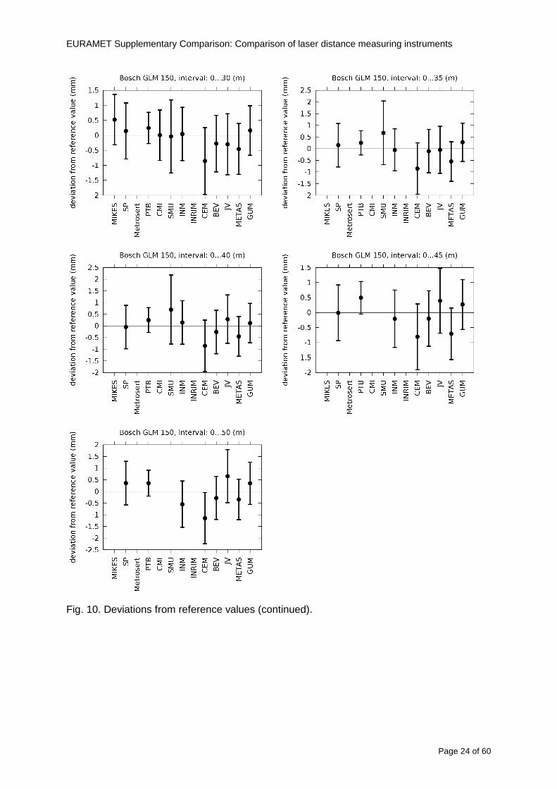
EURAMET Supplementary Comparison Comparison of laser distance measuring instruments
Page 24 of 60
Fig 10 Deviations from reference values (continued)
EURAMET Supplementary Comparison Comparison of laser distance measuring instruments
Page 25 of 60
Fig 10 Deviations from reference values (continued)
EURAMET Supplementary Comparison Comparison of laser distance measuring instruments
Page 26 of 60
Fig 10 Deviations from reference values (continued)
EURAMET Supplementary Comparison Comparison of laser distance measuring instruments
Page 27 of 60
Fig 10 Deviations from reference values (continued)
EURAMET Supplementary Comparison Comparison of laser distance measuring instruments
Page 28 of 60
Fig 10 Deviations from reference values (continued)
EU
RA
ME
T S
upplementary C
omparison C
omparison of laser distance m
easuring instruments
P
age 29 of 60
Table 8 Deviations from the reference value (given at the top of the table) and expanded uncertainties (k=196) of such deviations for BOSCH DLE 50
Table 9 Deviations from the reference value (given at the top of the table) and expanded uncertainties (k=196) of such deviations for BOSCH GLM 150
EU
RA
ME
T S
upplementary C
omparison C
omparison of laser distance m
easuring instruments
P
age 30 of 60
Table 10 Deviations from the reference value (given at the top of the table) and expanded uncertainties (k=196) of such deviations for Leica DISTO D3a BT
Table 11 Deviations from the reference value (given at the top of the table) and expanded uncertainties (k=196) of such deviations for Leica DISTO D8
EURAMET Supplementary Comparison Comparison of laser distance measuring instruments
Page 31 of 60
11 En Tables Results with En gt 1 are marked with red color in Tables below En values are calculated by Di U(Di) with Di and U(Di) as given on page 19
Table 12 BOSCH DLE50
Lab Distance (mm) 300 5000 10000 15000 20000 25000 30000 35000 40000 45000 50000
MIKES -058 017 -019 -023 035 -002 -096 SP 020 019 006 005 009 059 064 037 028 097 001
Metrosert -030 -031 -003 018 032 PTB 001 029 022 -006 011 -036 001 -023 -075 -083 001 GUM -033 -005 -018 -009 000 006 017 005 -026 -028 019 CMI -003 020 -009 004 005 -022 028 SMU 006 -049 -034 -023 -017 -057 051 039 021 INM 032 031 037 006 020 005 -079 -119 -272 -260 -269
INRIM 025 -013 000 096 CEM -032 -022 -041 -039 -004 -038 080 001 -094 -047 BEV -010 007 000 -001 008 -011 037 013 -001 008 -001 JV -019 -016 025 -055 055 060 068 163 122 060 089
METAS 038 012 -005 007 -107 004 -024 002 -070 037 -052
Table 13 BOSCH GLM150
Lab Distance (mm) 300 5000 10000 15000 20000 25000 30000 35000 40000 45000 50000
MIKES 005 -002 019 018 027 019 062 SP 003 068 029 023 051 008 015 016 -005 -001 038
Metrosert -061 -011 -022 -021 -003 PTB 066 074 062 062 034 053 047 048 047 091 064 GUM -007 -014 007 -018 000 023 020 033 014 032 038 CMI -057 -032 -030 -064 -050 -047 000 SMU 023 -024 -060 012 062 001 -003 050 047 INM -022 017 -003 002 -003 054 005 -006 016 -022 -055
INRIM 079 -052 -050 -026 -034 -042 CEM 002 002 -034 -020 -029 -077 -077 -077 -074 -104 BEV -004 -002 -007 010 -042 -042 -029 -011 -028 -022 -030 JV 003 015 040 011 -020 021 -029 -005 028 036 058
METAS -047 -020 005 002 -012 -033 -054 -065 -053 -082 -040
Table 14 Leica DISTO D3a BT
Lab Distance (mm) 300 5000 10000 15000 20000 25000 30000 35000 40000 45000 50000
MIKES 008 094 050 -011 028 051 045 SP 033 038 056 017 053 065 076 051 017 071 011
Metrosert -060 -004 -037 -014 -002 PTB 067 000 070 030 089 062 061 081 124 050 072 GUM 023 019 035 008 038 053 029 058 070 064 063 CMI -001 -004 027 -011 011 034 -033 SMU 002 -013 -019 007 -013 -055 045 -013 -042 INM 002 -039 -058 001 002 -045 -080 -051 -102 -101 -378
INRIM 070 -020 063 101 CEM -028 -004 -004 -064 003 -002 -050 -022 -093 -160 BEV -032 -019 -019 004 -011 -037 -017 -002 -025 005 012 JV 027 019 027 042 046 039 043 048 072 115 024
METAS -091 -008 -102 -098 -111 -103 -092 -080 -073 -108 -043
EURAMET Supplementary Comparison Comparison of laser distance measuring instruments
Page 32 of 60
Table 15 Leica DISTO D8
Lab Distance (mm) 300 5000 10000 15000 20000 25000 30000 35000 40000 45000 50000
MIKES 025 013 058 036 038 061 022 SP 057 026 040 016 013 016 025 017 -007 -019 007
Metrosert -021 006 -016 -043 -019 PTB 040 011 035 -005 -011 -002 -004 035 047 022 069 GUM -028 005 -025 031 039 -015 029 048 041 052 072 CMI -104 -026 -072 -057 -006 -017 -015 SMU -067 -017 -051 -026 -016 -054 -004 -001 -016 INM 021 -014 009 003 -017 -031 -010 007 029 036 041
INRIM 076 -024 -004 047 -007 083 CEM 004 -009 002 -033 -051 -059 -097 -077 -116 -134 BEV -057 -014 -051 -093 -024 -027 -021 -036 -038 -028 -041 JV 014 031 047 030 044 043 035 056 093 108 030
METAS 035 007 026 038 -013 -024 -011 -048 -089 -074 -066
12 Conclusions It was the first comparison of EDMs For most of the laboratories it was an important opportunity to validate their measurement instrumentation and procedure It allowed to become aware of potential problems and to take corrective actions in changing the procedure
For the evaluation of the reference value the weighted mean approach has been chosen although the consistency check according to procedure A of Ref [1] failed in many cases A more complicated procedure for the evaluation of the reference value was proposed which slightly changes the uncertainty of the reference value
In total there were 23 En values larger than 1 This represents 47 of the full set of 482 results It is less than the 5 of possible values being out of the expanded uncertainty of the reference value for k=2
The uncertainty of the results mainly comes from the uncertainty of the reproducibility It is difficult to distinguish between Labrsquos calibration and measurement capability
The comparison shows a global compliance with declared CMCs independently of whether some participant can have a high percentage of values not compliant with its CMC due to the influence of the artifact and the estimation of its uncertainty
13 References [1] M G Cox The evaluation of key comparison data Metrologia 39 589 ndash 595 (2002)
[2] R Thalmann EUROMET 677 ndash Steel Tape Measures Final report (2004)
[3] F Pollinger personal communication
EURAMET Supplementary Comparison Comparison of laser distance measuring instruments
Page 33 of 60
Appendix 1 Description of the measurement equipmen t as reported by the laboratories
A11 MIKES Finland
Short description of measurement bench
MIKES interferometric bench is situated in an underground laboratory with air temperature and humidity control Typically air temperature is 20 plusmn 01 degC and humidity 45 plusmn 2 RH The linear guide on the top of the concrete beam comprises two parallel round shafts with adjustable fixtures every 1 m A carriage with ball bush bearings is moved along the rail and location of it is measured with reference interferometer HP-5529A Temperature of air is measured with 6 pt100 sensors and Keithley 2010 multimetre with 4-wire resistance mode Air pressure and humidity are measured with Vaisala PTU200 Updated Edleacuten equation by Boumlnsch amp Potulski is used for calculation of refractive index of air
For EDM calibration on the other end than laser interferometer is a fixed reference plate which is adjusted perpendicular to the laser beam Next to the reference plate is an adjustable base for EDM instrument with which it can be adjusted to point parallel and coincident with measurement arm of the interferometer A target plate adjusted perpendicular to laser beam is fixed to the carriage The calibration followed Abbe principle with some millimetre uncertainty in offset adjustment
First reference interferometer is set to zero when the target plate and reference plate are in contact then EDM is positioned and adjusted in its base The rear surface of the EDM is also slightly pressed against reference surface behind it Then the readings from both instruments are collected at selected locations For this calibration there is no fine adjustment of the target position so there are typically deviations of up to few millimetres from nominal locations Results are averages of 3-4 measurements
Additional remarks
The CMC entry MIKES has for EDM calibrations is based on calibration of length scales of high quality total stations and laser trackers This type of EDMs used in this comparison are not accurate enough for truly testing of MIKES calibration measurement capability
EURAMET Supplementary Comparison Comparison of laser distance measuring instruments
Page 34 of 60
A12 SP Sweden
Short description of measurement bench
The bench consists of a simple aluminium Uminusshaped profile with polished steel pins acting as supports for the tape The bench is a little over 50 m long and works as support for the reference tape and the calibrated EDMs simultaneously
Length measurement instrument
Comparison with reference steel tape
Temperature measurement system number and location of sensors
The tape temperature is continuously registered in 6 points equally distributed along the bench The air temperature is monitored during the measurements but not used for corrections
Additional remarks
The EDM support is placed approximately 2 cm vertically above the tape No visual aid is used
EURAMET Supplementary Comparison Comparison of laser distance measuring instruments
Page 35 of 60
A13 AS Metrosert Estonia
Short description of measurement bench
The 21-m bench is located in the designated corridor-like laboratory room The lab is air-conditioned and the stability of temperature is typically plusmn05 ordmC There are three humidity and temperature sensors in room for stability and gradient monitoring
Two stainless steel rails running in parallel are made of 3-m long rods The rails lay without fixed attachment on metal supports which are mounted on concrete base The base rests on pillars made of bricks
Length measurement instrument
Laser-interferometer system Renishaw ML10 was used as length measurement instrument
Laser interferometer gets temperature humidity and pressure data from itrsquos own measurement system EC10
Additional remarks
Due to the length of the bench only measurements up to 20 m could be made Five measurement series were made with each EDM
EURAMET Supplementary Comparison Comparison of laser distance measuring instruments
Page 36 of 60
A14 PTB Germany
Short description of measurement bench
The measurements were performed on the 50 m geodetic base of the PTB The comparator consists of a 50 m rail The laboratory is equipped with a network of 21 temperature sensors spaced by 25 m along the bench As depicted in fig 1 the EDM is mounted at one end of the comparator the reflector is fixed vertically on the carriage A large retroreflector is mounted approximately 150 mm below the EDM reflector on the carriage reflecting the beam of the reference interferometer The deviation of the length due to tilting carriage (Abbe error) has been investigated along the bench by comparison of two interferometers It remains smaller than 100 microm The distance of the first position of 300 mm with respect to the back side of the EDM is determined by a gauge block of 300 mm length and a thickness of 10 mm This procedure is depicted for one of the comparison standards in figure 2
For the calibration the desired positions are programmed After the carriage reaches a measurement position the operator waits for another 30 s for the carriage to settle In control experiments the remaining movement between positioning and measurement remained smaller than 2 microm The operator then activates the measurement of the EDM reads the indicated position and writes it down The procedure is repeated for twelve times at every position the mean of the 12 measurements represents the ldquoindicated distance by the EDMrdquo All measurements of a single run at one position are performed within approximately one minute The complete measurement was repeated for four times
Length measurement instrument
The reference length is determined by a frequency-calibrated laser interferometer (Agilent 5519A) The reference interferometer is set up in Michelson geometry the signals being digitalised by a Heidenhain IK 121 card The index of refraction is determined by the external weather station of the geodetic base consisting of 21 Pt-100 temperature sensors spaced 25 m along the bench two humidity sensors (Testo 650) and two pressure sensors (Setra 370 and DPI 141) The environmental parameters are used to determine the index of refraction for the reference measurement deploying the modification of the Edleacuten equation by Boumlnsch and Potulski
EURAMET Supplementary Comparison Comparison of laser distance measuring instruments
Page 37 of 60
A15 CMI Czech Republic
Description of measurement bench
The EDMs were measured on 30 m long measuring bench equipped by laser interferometer (LI) Renishaw ML10 (pic 1 and 2) calibrated traceable to national standard of length and quantities of environmental sensors The target plate and retroreflector of the LI were fixed on a moving part of the bench and each EDM was fixed in horizontal position by clamps (pic 3) LI and EDM are placed on opposite ends of bench the Abbe offset was lt10 mm for some of them and lt50mm for all The value of LI was reset (to zero) at position corresponding to the rear of the EDM (using 3D measuring arm FARO Quantum with uncertainty about 27microm) The perpendicularities of the EDM stop as well as target plate to the beam were also checked by FARO) Each EDM was 3x replaced and aligned the measurement (reading) was repeated 6 times for each alignment and position the mean value of these 3x6 measurements is stated in tables with results The uncertainty claimed covers the statistical uncertainty of single readings Only in case of Leica D8 (the best performing EDM in this comparison) we state also the uncertainty corresponding to the mean of 6 readings in last column (this uncertainty is smaller and better illustrates our CMC)
Length measurement instrument
- Laser interferometer Renishaw - Laser 633 nm Type ML10 - Compensator EC10 - 3D measuring arm FARO Quantum - 3D measuring arm FARO Quantum
EURAMET Supplementary Comparison Comparison of laser distance measuring instruments
Page 38 of 60
A16 SMU Slovakia
Short description of measurement bench
No bench is available at the SMU the measurements are being carried out in the underground corridor of the laboratory building with length of 428 m
The 50 m steel measuring tape KINEX was used as the reference laid on the floor and pulled by the force 50 N (the same force as had been applied during its calibration at the SMU) The calibration of reference tape was done at the SMU using ULM3m Zeiss with laser interferometer Agilent 5529 B (ie per 3 m parts)
Three mercury thermometers with the resolution of 01 degC were used along the measurement path each of them laid onto the tape and located at 667 m 1990 m (instead of 20 m because of this was one of measuring points) and 333 m respectively Each of them thus corresponded approximately to one third of the measured steel tape section
Regarding the 03 m measuring point the ULM3m Zeiss length measuring machine was used with the 300 mm gauge block as the reference
Length measurement instrument
We used our own target plate being fixed perpendicularly (within uncertainty stated) to the construction equipped with nonius and the camera holder transported manually along the steel tape The second construction was fixed to the tape by such a way that zero line of the tape corresponded to the rear of EDM (within uncertainty stated)
The position of the target is read on the monitor and 20 repeated readings of the EDM data took place in each measuring point (multiples of 5 m up to 40 m)
Concerning 03 m the 300 mm gauge block was fit between the target plate and the construction with EDM The distance of the EDM rear from the target plate corresponded to the length of gauge block (within uncertainty stated)
Additional remarks
The identical measurement method was used as we use to do within our calibration service although the results reporting is different ndash we provide the regression line calculated from the measurement of irregularly distributed points and corresponding uncertainty (k = 2) in the form of [a bL] mm (ie the same coefficients for each length in the range (0 ndash 42) m)
SMU hasnrsquot got this category in CMC tables
EURAMET Supplementary Comparison Comparison of laser distance measuring instruments
Page 39 of 60
A17 INM Romania
Short description of measurement bench
Geodesic base located in the basement of the laboratory with nominal length equal to 50 m having a mobile carriage thet support both laser He-Ne retroreflector and the target of the laser distance measuring instrument in the front of geodesic base exists a support where are aligned both laser interferometer and the laser distance measuring instruments
Length measurement instrument
Laser interferometer type Hewlett Packard model 5526 A with nominal length equal to 50 m resolution 0001 mm
U = 02 microm +0510-6L
Additional remarks
During the measurements the maximum gradient of temperature was equal to 05 degC
EURAMET Supplementary Comparison Comparison of laser distance measuring instruments
Page 40 of 60
A18 INRIM Italy
Short description of measurement bench
The facility for long distance measurements is located in a corridor of the gallery devoted to dimensional metrology The structure consists in a 28 m long rail fixed to a series of pillars which rest directly on the ground released from the vibrations of floor and wall The measuring system is based on a heterodyne interferometer whose mobile arm consists of a hollow retro-reflector mounted on a structure that can run along the rail so-called carriage A photograph of the facility is presented in Fig1
The carriage is moved by a micro-step motor the motor driver receives a digital pulse and converts it into an electrical pulse to run the motor Each pulse causes a rotation of the motor shaft of one step which amounts to 11000 of a complete revolution of the shaft If the pulse frequency increases the rotation becomes continuous with a speed that is directly proportional to the pulse frequency The speed ranges between few microms up to 27 ms with a resolution of 03 microms
Since the carriage must move back and forth automatically for a distance of almost 30 m a remote control to send pulses to the motor driver was implemented It consists of two parts a radio command which allows to set some general parameters of the carriage movement such as the movement direction and mode of travel (slow or fast) and a fast command which is performed by an amplitude modulated laser beam placed at the beginning of the track oriented towards the carriage A photo detector placed above the carriage receives the modulated laser beam which is transformed into pulses to be sent to the driver of the motor The modulation of the laser beam is implemented by a LabView program that controls a digital output of the data acquisition device
Length measurement instrument
The length measurement instrument is based on a heterodyne incremental interferometer The main beam of the interferometer with frequency f1 is generated by a frequency stabilized
EURAMET Supplementary Comparison Comparison of laser distance measuring instruments
Page 41 of 60
He-Ne laser calibrated with respect to the INRIM length standard and sent to the measurement arm the second beam is a portion of the first one diffracted by an acousto-optic modulator (AOM) with frequency f2 = f1 + 80 MHz The reference detector acquires the beat note signal at 80 MHz while the measurement detector acquires a signal at 80 MHz whose phase is varied due to the displacement of the retro-reflector moving on the rail In figure 2 the optical design of the interferometer is presented
Two different measuring techniques have been implemented
1 the ldquophase measuringrdquo technique based on fringes counting with a relative uncertainty of 5middot10-7 but limited at the maximum carriage speed of 3 cms
2 the ldquoDoppler frequency measurementrdquo technique for higher carriage speed based on the measurement of the Doppler frequency shift while the carriage runs
The second technique was validated by means of the comparison with the first technique at low speed with an agreement of the order of 3middot10-6 hence the Doppler frequency method could be considered validated within 01 mm over the whole rail path with the advantage of reducing the time needed to cover long distances so it was used for the EDM comparison
In order to obtain the distance covered by the carriage according to technique 2 the Doppler frequency is measured by a commercial high-performance counter (a Pendulum CNT-90) without dead time based on time stamping then it is converted in speed and integrated over time according to the following formula
( ) ( )int minus=minus= tffn
dtn
ffdairair
λλ
2
1
2
1
where d is the distance covered by the carriage f is the frequency of the measuring signal with the carriage at rest frsquo the frequency of the measuring signal with the carriage moving λi
is the wavelength of the laser in vacuum n - air is the air refractive index and ti is the integration time The difference frsquo-f is just the Doppler frequency due to the moving carriage
The time interval measurement resolution of the instrument is 100 ps and the time base is
EURAMET Supplementary Comparison Comparison of laser distance measuring instruments
Page 42 of 60
connected to the INRIM UTC so that the measurements of the Doppler frequency and the integration time are extremely accurate The environmental parameters such as air temperature atmospheric pressure partial pressure of water were monitored during the measurement process in order to calculate the value of air refractive index according to the Edlenrsquos formula
Comparison set-up
The different technical solutions adopted for the EDMs and for the target plate positioning are discussed in this paragraph and sketched in figure 3
Fig 3 picture of the EDM and target positioning area
Target plate positioning
In order to use the provided target plate an ad-hoc mounting was manufactured at INRIM it consists in a sort of picture frame made in aluminum which slightly clamps the target folded in half and gives it the necessary stiffness to be a reproducible target The upper part of the frame is L-shaped and allows it to be fixed to the carriage structure by means of two screws The rear part of the target mounting is depicted in figure 4 The target mounting was considered necessary because of the poor stiffness and planarity of the plastic target With the aluminium frame a planarity better than 01 mm was guaranteed The target plate is placed few centimetres next to the retro-reflector and normal to the interferometer beam axis since the EDM laser should be as close and parallel as possible to the reference beam
EURAMET Supplementary Comparison Comparison of laser distance measuring instruments
Page 43 of 60
Fig 4 picture of the rear part of the target plate mounting
EDMsrsquo positioning
The EDMs are placed on a cradle-like platform which is able to adjust the inclination of the EDM along the longitudinal axis (pitch angle) The platform height allows the EDMs to be at approx the same height as the interferometer beam A crucial role was played by the stop-wall placed behind the platform since it represents the ldquozero pointrdquo for all the length measurement Hence a particular effort was devoted to align the stop-wall so that it was normal to the interferometer beam axis and parallel to the target plate
Fig 5 detail of EDMsrsquo positioning the cradle-like platform and the stop-wall are well visible
EURAMET Supplementary Comparison Comparison of laser distance measuring instruments
Page 44 of 60
Target and stop-wall alignment
In order to have the stop-wall parallel to the target plate and normal to the interferometer beam axis the following procedure has been used
1) the stop-wall and the target plate were roughly placed trying to set them parallel and normal to the rail by eye (ie within few millimeters)
2) in order to check if the target was normal to the rail one EDM was positioned on the platform the pitch and yaw angles of the EDM were adjusted by observing the position of the EDM laser spot on the target plate when the target is moved along the rail fixed position means laser beam parallel to the carriage movement Then the target was moved until the end of the rail and a thin mirror was kept in contact with it hence observing the EDM laser reflected by the mirror it was possible to adjust the target tilt acting on the screws until the laser beam is reflected back to the source
3) finally in order to check the parallelism between the stop-wall and the target a tool made by a laser pointing orthogonally to its base was used the base was leant against the stop-wall and the laser was centered on the target when the target is near then the target was moved until the end of the rail hence observing the spot of the laser on the target it was possible to adjust the stop-wall orientation
The residual misalignment errors which we were not able to eliminate were kept into account in the uncertainty budget
Measurement of the first 30 cm
Due to the geometry of our set-up it was not possible to perform the first point of measurement by means of the interferometer indeed the carriage (hence the target) is not able to go in contact with the stop-wall
Fig 6 measurement of the first 30 cm the ruler touching the stop-wall and the target and the mechanical probe (in the back) touching the carriage are visible
EURAMET Supplementary Comparison Comparison of laser distance measuring instruments
Page 45 of 60
So a ruler made of aluminum with rounded ends and nominal length equal to 30 cm was adopted to set the distance between the target plate and the stop-wall for the first point of measurement as it is shown in figure 6 The ruler whose length was measured by a CMM machine was inserted between the target and the stop-wall leaning against the latter and the carriage was carefully moved towards the stop-wall until the target lightly touched the ruler A mechanical probe that touches the carriage structure when carriage is in the ldquo30 cmrdquo position was used as a reference measurement to check the repeatability of this distance after each measurement set
Fig 7 detail of the mechanical probe touching the carriage
Environmental parameters
The environmental parameters such as air temperature atmospheric pressure and humidity were monitored during the whole measurement process in order to calculate the value of air refractive index according to the Edlenrsquos formula
Among these parameters the temperature distribution along the mobile arm of the interferometer was our main concern mainly for two reasons
1 the temperature control of the gallery was not perfectly working during the measurement period so temperature drifts had to be monitored
2 longitudinal temperature gradients due to non uniform heating and to the presence of electronic instruments were pretty high
To the purpose 14 thermometers were uniformly dislocated along the rail and automatically recorded for all the measurement period Both temporal drifts and gradients along the path have been taken in account in the uncertainty budget In any case maximum temperature differences along the rail are within 1 degC In fig 8 an extract from the acquisition file is shown
Unfortunately the air conditioning system did not work well during the measurement campaign hence the measurements were performed at a mean temperature of 209 degC
EURAMET Supplementary Comparison Comparison of laser distance measuring instruments
Page 46 of 60
Fig 8 each curve represents the temperature distribution along the rail during the measurements campaign
Carriage waving
Since the rail is not perfectly straight and the measurement laser is not coincident with the measurement beam the Abbegrave error due to waving of the target must be considered A quantitative measurement and a qualitative measurement were carried out With an electronic level placed on the carriage the straightness on the vertical plane has been mapped with a half meter resolution (the data are reported in fig 9) With a laser placed on the carriage the horizontal and vertical waving are qualitatively compared by looking at the movements of the light spot on a target fixed to the rail end As a conclusion the horizontal and vertical waving are comparable in magnitude and the peak to peak error is of the order of 300 arcseconds
Fig 9 vertical waving of the target measured by an electronic level placed on the carriage
EURAMET Supplementary Comparison Comparison of laser distance measuring instruments
Page 47 of 60
Measurement procedure
The measurements were carried out according to the following procedure
The target was set in the starting position with the procedure described above
In sequence the four EDMs are positioned on the base the horizontal and vertical tilt are adjusted and the distance measurement is recorded An additional fifth EDM (Bosh DLE 150 property of INRiM) was included in the measurement sequence Each EDM is placed on the base and gently pushed against the reference wall in such a way that the measurement laser beam starting point is the same for all EDMs Than the horizontal and vertical angles were adjusted in order to hit the central point of the target indicated with two black marks (see pictures 3 and 6) with ldquovisualrdquo alignment The measurement button is then pressed several times (typically 5) and the average reading is recorded Typical dispersion between readings is within few last digit units In case the dispersion between readings is too large the anomaly is recorded
The carriage was then moved in the next position (about 5 m) and the measurement sequence was repeated for the 5 EDMs The operation is repeated up to 25 m The 25 m measurement is than repeated again as well as all the points till the first one so that each point is measured twice each set Since the carriage movement is ldquoopen looprdquo the positioning of the carriage was not exactly in the nominal 5 m intervals For each positioning the incremental displacement is measured by the interferometer in the Doppler mode Finally the measured values were averaged in order to give a single value for each nominal position
At the end of the measurement set when the carriage is at the 30 cm position again the sum of the interferometric measurements should be very close to zero The residual value is compared with the difference between the first and the final measurements of the mechanical probe The difference must be within the uncertainty of the Doppler technique otherwise some error occurred in the measurement set that must be repeated
At the end of the session 10 complete sets of measurements recorded from the 20th to the 30th of January 2012 have been considered for this report
Additional remarks
Effect of laser pointing
During a preliminary set of measurements we noticed a strong and unexpected dependence of the measurement result on the position of the laser spot on the target Indeed since no particular instructions were given about the relative position of the laser spot on target position (except to exclude the central joint between the two halves) we decided to work relatively close to the right side of the target -closer to the interferometer beam- in order to reduce the Abbegrave error We noticed very large errors at large distances in particular of the Leica DISTO D3a (see figure 10)
EURAMET Supplementary Comparison Comparison of laser distance measuring instruments
Page 48 of 60
Fig 10 errors of each EDM In a preliminary set of measurements
We also noticed that this error was strongly dependent on the position of the spot on the target For this reason we carried out a set of measurements at the maximum length in different positions of the target from one edge to the other according to figure 11 The results are reported in table V
EDM A B C D E
Leica D3a -4 +1 0 +24 +43
+2 0 +42 +40
-1 0 +38
Leica D8 0 0 0 2 +7
0 +12 +23
table V deviations (in mm) from the length measured at point C aiming the laser spot at different positions of the target (notations as in figure 11)
We tried to find an explanation to this effect in the shape of the laser spot if the spot was
EURAMET Supplementary Comparison Comparison of laser distance measuring instruments
Page 49 of 60
particularly defocused or had high diffraction some of the energy could fall out of the target and affect the measurement result In fact the images of the spots (shown in fig 12) do not support this hypothesis Finally we decided to use the center of the (half) target for the comparison
Changing the target
In order to investigate the influence of the target on the measurements a cardboard foil (400 x 400) mm was fixed to the target mounting and a complete set of measurements was performed The results reported in figure 13 and 14 do not show any evidence of a possible dependency of the EDM measurement on the target kind
EURAMET Supplementary Comparison Comparison of laser distance measuring instruments
Page 50 of 60
Measurement at 50 m
Although we are not able to perform traceable length measurements beyond 28 m we wanted to get a sense of EDMs behaviour at longer distances So a target (represented by a rack side wall) was placed at approximately 50 m one after the other the EDMrsquos were positioned on the base and pointed towards the target The measurements were repeated then the target was replaced by the target used for the comparison and a third set of measurements were performed To our great surprise all the EDMrsquos were in good agreement (within 2 or 3 mm for each set of measurement) even those which showed errors of the order of five to ten millimeters at 25 m namely BOSCH DLE 50 and LEICA DISTO D3a Therefore each set of measurements was averaged and the deviations from the mean value are reported in figure 15
EURAMET Supplementary Comparison Comparison of laser distance measuring instruments
Page 51 of 60
Fig 15 Deviations from average value of the measurements At 50 m
EURAMET Supplementary Comparison Comparison of laser distance measuring instruments
Page 52 of 60
A19 CEM Spain
Short description of the measurement bench
To make the measurements of EDMs we have used a reference line made of adjustable supports fixed on a wall of the laboratory Each support is nominally separated five metres from the previous one so we can generate reference lengths up to fifty metres with a pitch of five metres The supports are designed to accommodate both targets and handheld EDMs Distances between supports were measured by using a total station traced to national standards The relative angles of the bases have been measured and corrected
Fig 1 - View of three consecutive supports of the 50 m baseline (left) Lab technician situating an EDM on the first support of the baseline (right)
Length measurement instrument
The baseline was calibrated by using a total station Leica TDA5005 with spherical reflector the calibration uncertainty being 02 mm for k = 2
The target is provided by the comparison The quality of the target was judged as not good due to geometrical constructive errors and the lack of rigidity and stability We measured the flatness of the target surface the distance edge-surface and the angle between them by using a 3D coordinate measuring machine The results of flatness and angle were included in the uncertainty budget and the distance EDM-target was corrected for each EDM due to each beam impinged on a different point of the target
We were not able to measure the distance 0 to 03 m because the baseline pitch is 5 meters and although we are able to measure shorter values in a different facility the target was not appropriate for our bench
EURAMET Supplementary Comparison Comparison of laser distance measuring instruments
Page 53 of 60
Fig 2 - View of an EDM on the first support of the baseline (left) A closer look showing the support adjustments and the origin plate (right)
Fig 3 - View of the comparison target on one of the supports of the baseline (left) A closer look showing the target edge against the support rigid reference (right)
Measurement method
The measurements were carried out by comparison against the known values of the calibrated baseline (metallic references on supports)
Environmental conditions were maintained within the following limits
- Temperature 20 ordmC plusmn 05 ordmC
- Humidity 45 plusmn 10
Each laser distance measuring instrument was placed at the first support of the base and aligned so that the laser beam was perpendicular to the target as indicated by the comparison protocol
For each measurement we took the average of thirty measurements It permitted us to evaluate the repeatability of the instrument
EURAMET Supplementary Comparison Comparison of laser distance measuring instruments
Page 54 of 60
A110 BEV Austria
Short description of the measurement bench
Fig 1 Carriage of tape bench View from the laser interferometer side Retroreflector mounted on the vertical plate the EDM target is mounted on the backside
Fig 2 Support for the DUT Adjustable with 2 translational and 2 rotational degrees of freedom respectively
Fig 3 Setting of the 300 mm starting position Note the rough-and-ready mounted target plate
Fig 4 Laser interferometer side of the bench The DUT is 50 m away on the other side
EURAMET Supplementary Comparison Comparison of laser distance measuring instruments
Page 55 of 60
Measurement procedure 1 The EDM is positioned with the help of a 4-axis positioning stage so that its laser beam is
coaxial with the measurement direction of the laser interferometer (in head on configuration)
2 The EDM is removed from its support The bench carriage is positioned so that the distance of the target plate from the EDM back support is 300 mm A length bar with spherical faces is used for this adjustment The laser interferometer is preset to 300 mm and the EDM is put back on its support
3 At each position 10 consecutive measurements are taken (repeatability) and the carriage is moved to the next position The carriage is manually moved under control of the laser interferometer until it is within plusmn30 microm at the correct position (Exception for the DLE 150 the target is not positioned at 10 m but at 10 m ndash 1 mm to make use of the higher resolution) The indicated (not the nominal) distance of the laser interferometer is recorded for the determination of the deviation
4 After reaching the 50 m position all points are measured in reverse order (bidirectional) Immediately after the last measurement the EDM is removed and the indication using the 300 mm length bar is checked (thus noting a possible drift of the setup)
5 Each instrument was measured 4 times according to this procedure on different days (reproducibility of bench and instrument)
Length measurement instrument
Agilent laser interferometer with long range option The bench was completed short time before performing these measurement So the characterisation was not complete and the respective measurement uncertainty of the laser interferometer is estimated rather high But anyway its contribution to the overall uncertainty can nearly be neglected
Additional remarks
The uncertainty originating from the DUT is the dominating uncertainty contribution Specifically the resolution of the two Bosch instruments (1 mm) and the repeatability are the largest contributions For the DLA 50 the pooled standard deviation of a reading at 50 m is larger than 2 mm Moreover the length dependence is not a simple function
All of the instruments show a significant deviation of the laser beam from the normal of the back (reference) face of the instrument The measured angles reach from 04deg (D3a) to 11deg (DLE 50) This leads depending on the outer dimensions of the instruments to a constant uncertainty contribution of 02 mm in our setup It must be noted that the reference faces are not well defined in most of the instruments
The reproducibility is quite different for the four instruments so only part of it originates from the setup For CMC claims we will use the standard uncertainty value of the most reproducible instrument (D3a) which amounts to 013 mm For an ideal instrument with a resolution of 01 mm and perfect repeatability we would thus have a constant expanded uncertainty of 053 mm up to 50 m
EURAMET Supplementary Comparison Comparison of laser distance measuring instruments
Page 56 of 60
A111 JV Norway
Short description of measurement bench
EDM under calibration and the reference system are aligned along a 50 m measurement bench with rails to carry the linear movement of a target plate for the EDM and a corner cube reflector for the reference system The distance between parallel axis of EDM and axis of the reference system is 130 mm Abbe error due to angle errors for the movement is smaller than 01 mm and is corrected for at each measurement point At long lengths an aperture is used approximately midway between the target plate and the EDM to avoid interfering stray light to the EDM
Alignment procedure
1) Alignment of reference system to the movement of the carriage (rails)
2) Alignment of the EDM to the movement of the carriage (rails)
3) Alignment of a plane mirror at the position of the target plate using back-reflection to the EDM output (normal incident of light on the mirror)
4) Take out the EDM and align the zero reference plate at the back of the EDM to the plane mirror
5) The mirror is replaced by the target plate and the target plate is aligned to the zero reference plate
6) Zero setting of the reference measurement system when target plate is at zero distance to the reference plate at the back of the EDM
7) Put the EDM back in position and realign it to the movement of the carriage (rails)
8) Zero setting of the EDM to the reference plate
Image 1) Image 2) Image 3) Image 4)
Image 1) Items 5) ndash 6) in alignment procedure
Fixture for HP linear interferometer is seen bottom right Part of Wyler instrument is seen to the left blue colour
Image 2) Items 7) and 8) in alignment procedure
Micrometer screws for angle alignment in two directions and linear translation for zero setting of the EDM Push button on the EDM is positioned at the tilting point of the angle adjustment table to maximize stability during measurement HP 5519 A laser head is seen to the right
Image 3) Ready to measure at selected distances from zero point the reference plate
Image 4) EDM spot size at 50 m
Length measurement instrument
- Hewlett Packard Dynamic Calibrator 5519 A (max range 80 m)
- Pressure air temperature humidity Vaisala
EURAMET Supplementary Comparison Comparison of laser distance measuring instruments
Page 57 of 60
- Digital high resolution angle measurement Wyler
I used our own target plate which is of the same type as enclosed in the artefact suitcase article number 766560 from Leica but with reduced size width x hight = 90 x 137 mm
The zero reference plate is of similar type and size
Before measurements batteries of EDMs were switched to new batteries Old batteries are switched back after calibration
For L gt 5 m an aperture of similar size as the target plate is used approximately midway between the EDM and the target plate
Additional remarks
Reports on EDM indicated values at each measurement point is the average value of n = 5 repetitions A linear model of the standard deviation for the repeatability of the EDM readings at different lengths is estimated using m = 20 repetitions at least 5 positions along the scale An estimate of the length dependent repeatability is made for each instrument
The expanded uncertainty U(95) is rounded up to the limiting resolution of 1 mm in the interval 10 m to 40 m for Bosch GLM 150
After the calibration we also estimated the angle error of the optical axis of the EDM to its back plane (back reference of EDM) Bosch DLE 50 26 mrad up measured at 50 m Bosch GLM 150 8 mrad to the left measured at 50 m Leica DISTO D3a 37 mrad down measured at 20 m Leica DISTO D8 2 mrad to the left and 4 mrad down (45 mrad total) measured at 20 m
The distance between parallel walls will be measured too large if the back plane is assumed to be normal to the optical axis of the EDM by ∆LL = (1cosα ndash 1) Bosch DLE 50 ∆LL = 340 ppm (∆L = 17 mm at L = 50 m) Bosch GLM 150 ∆LL = 32 ppm (∆L = 16 mm at L = 50 m) Leica DISTO D3a ∆LL = 7 ppm (∆L = 034 mm at L = 50 m) Leica DISTO D8 ∆LL = 10 ppm (∆L = 05 mm at L = 50 m)
EURAMET Supplementary Comparison Comparison of laser distance measuring instruments
Page 58 of 60
A112 METAS Switzerland
Short description of measurement bench (photo recom mended)
50 m bench with laser interferometer (see photo detailed description in Michel Degoumois Un Long laboratoire de mesure OFMETinfo Vol5 No 2 1998)
Length measurement instrument
HP 5529 B laser interferometer range 80 m
EURAMET Supplementary Comparison Comparison of laser distance measuring instruments
Page 59 of 60
A113 GUM Poland
Short description of measurement bench
The 50 m bench is situated in the corridor laboratory located in the basement and has its own air conditioning system with air temperature 20 plusmn 1 degC and humidity 50 plusmn 10 RH The measuring carriage is carried microscope with CCD camera and the optics associated with the interferometer The carriage is driven using belt-transmission and electrical engine with remote ndash controlled variable speed drive
The EDM was placed on the fixed adjustable plate on the other end than laser interferometer The target plate of the EDM was placed on the measuring carriage For each EDM 3 series of measurement were done Before the each measurement EDM was repositioned and aligned again
Length measurement instrument
1 Laser interferometer HP 5529A with long-range option laser head HP 5519A
2 Ambient measurement system number and location of sensors - 20 air temperature sensors type YSI with KEITHLEY multimeter they are placed very
close to axis of the laser beam - air pressure and humidity are measured with Vaisala barometer and
thermohigrometer - CO2 content was measured with analyzer made by Intelli Charge type SPN 4462
EURAMET Supplementary Comparison Comparison of laser distance measuring instruments
Page 60 of 60
Appendix 2 Corrections of reports
131 CEM Spain
CEM reported two errors in their report
1) Bosch GLM 150 EDM error for 35 m should be -08 mm instead of the indicated 08 mm
2) Leica DISTO D8 EDM error for 35 m should be -019 mm instead of the indicated 019 mm
Proposed corrections have been included in Tables 2 and 4 of the Final Report
132 AS Metrosert Estonia
AS Metrosert reported mixed up of all results for Bosch DLE 50 and Bosch GLM 150 The results and uncertainties sent for DLE 50 was results for GLM 150 and vice versa
Proposed corrections have been included in Tables 1 and 2 of the Final Report
133 INRIM Italy
Among the data reported from INRIM some anomalies were found in the measurements of BOSCH DLE 50 and LEICA DISTO D3a at distances of 20 and 25 m
After preliminary discussion on Draft A it was understood that those anomalies could be explained as a sensitivity of said instruments to the laser light that once diffused by the target is reflected by surfaces parallel to the measurement axis and detected together with the wanted signal The superimposition of the two signals can cause a ldquopullingrdquo effect leading to an overestimation of the distance being the reflected path always longer than the direct one Indeed in the INRIMrsquos set-up the target was mounted pretty close to the flat rail used for the carriage movement being likely responsible for unwanted reflections that disturbed the measurements
Since the errors reported in INRIMrsquos measurements can be ascribed to a defect of BOSCH DLE 50 and LEICA DISTO D3a andor to a lack of description of the working conditions of said instruments INRIM asked to eliminate its measurement points at 20 and 25 m of said instruments from the comparison
Proposed corrections have been included in Tables 1 and 3 of the Final Report
134 JV Norway
Justervesenet has changed the procedure and introduced two apertures instead of only one aperture (iris) which was positioned at half distance between EDM and target The reason is that the reference beam also has an aperture and it is positioned right below the beam from the EDM (130 mm distance between axes) Some diffusively reflected stray light from the EDM target might enter the aperture for the reference beam reflect at the measurement table and reach the detector of the EDM In our calibration set-up we have only seen problems at L gt 30 m We will position the first aperture at ca 5 m from the EDM and then the second aperture at ca 25 m This combination of two apertures will effectively eliminate interference of stray light from the measurement table to the EDM detector for all lengths up to 50 m
Justervesenet also increases the uncertainty component regarding repeatability reproducibility so that the expanded uncertainty increases from 14 mm to 15 mm
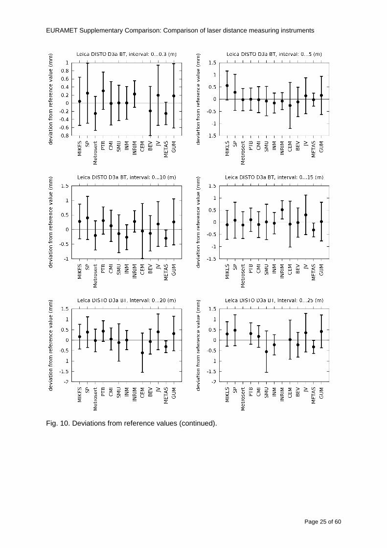
EURAMET Supplementary Comparison Comparison of laser distance measuring instruments
Page 25 of 60
Fig 10 Deviations from reference values (continued)
EURAMET Supplementary Comparison Comparison of laser distance measuring instruments
Page 26 of 60
Fig 10 Deviations from reference values (continued)
EURAMET Supplementary Comparison Comparison of laser distance measuring instruments
Page 27 of 60
Fig 10 Deviations from reference values (continued)
EURAMET Supplementary Comparison Comparison of laser distance measuring instruments
Page 28 of 60
Fig 10 Deviations from reference values (continued)
EU
RA
ME
T S
upplementary C
omparison C
omparison of laser distance m
easuring instruments
P
age 29 of 60
Table 8 Deviations from the reference value (given at the top of the table) and expanded uncertainties (k=196) of such deviations for BOSCH DLE 50
Table 9 Deviations from the reference value (given at the top of the table) and expanded uncertainties (k=196) of such deviations for BOSCH GLM 150
EU
RA
ME
T S
upplementary C
omparison C
omparison of laser distance m
easuring instruments
P
age 30 of 60
Table 10 Deviations from the reference value (given at the top of the table) and expanded uncertainties (k=196) of such deviations for Leica DISTO D3a BT
Table 11 Deviations from the reference value (given at the top of the table) and expanded uncertainties (k=196) of such deviations for Leica DISTO D8
EURAMET Supplementary Comparison Comparison of laser distance measuring instruments
Page 31 of 60
11 En Tables Results with En gt 1 are marked with red color in Tables below En values are calculated by Di U(Di) with Di and U(Di) as given on page 19
Table 12 BOSCH DLE50
Lab Distance (mm) 300 5000 10000 15000 20000 25000 30000 35000 40000 45000 50000
MIKES -058 017 -019 -023 035 -002 -096 SP 020 019 006 005 009 059 064 037 028 097 001
Metrosert -030 -031 -003 018 032 PTB 001 029 022 -006 011 -036 001 -023 -075 -083 001 GUM -033 -005 -018 -009 000 006 017 005 -026 -028 019 CMI -003 020 -009 004 005 -022 028 SMU 006 -049 -034 -023 -017 -057 051 039 021 INM 032 031 037 006 020 005 -079 -119 -272 -260 -269
INRIM 025 -013 000 096 CEM -032 -022 -041 -039 -004 -038 080 001 -094 -047 BEV -010 007 000 -001 008 -011 037 013 -001 008 -001 JV -019 -016 025 -055 055 060 068 163 122 060 089
METAS 038 012 -005 007 -107 004 -024 002 -070 037 -052
Table 13 BOSCH GLM150
Lab Distance (mm) 300 5000 10000 15000 20000 25000 30000 35000 40000 45000 50000
MIKES 005 -002 019 018 027 019 062 SP 003 068 029 023 051 008 015 016 -005 -001 038
Metrosert -061 -011 -022 -021 -003 PTB 066 074 062 062 034 053 047 048 047 091 064 GUM -007 -014 007 -018 000 023 020 033 014 032 038 CMI -057 -032 -030 -064 -050 -047 000 SMU 023 -024 -060 012 062 001 -003 050 047 INM -022 017 -003 002 -003 054 005 -006 016 -022 -055
INRIM 079 -052 -050 -026 -034 -042 CEM 002 002 -034 -020 -029 -077 -077 -077 -074 -104 BEV -004 -002 -007 010 -042 -042 -029 -011 -028 -022 -030 JV 003 015 040 011 -020 021 -029 -005 028 036 058
METAS -047 -020 005 002 -012 -033 -054 -065 -053 -082 -040
Table 14 Leica DISTO D3a BT
Lab Distance (mm) 300 5000 10000 15000 20000 25000 30000 35000 40000 45000 50000
MIKES 008 094 050 -011 028 051 045 SP 033 038 056 017 053 065 076 051 017 071 011
Metrosert -060 -004 -037 -014 -002 PTB 067 000 070 030 089 062 061 081 124 050 072 GUM 023 019 035 008 038 053 029 058 070 064 063 CMI -001 -004 027 -011 011 034 -033 SMU 002 -013 -019 007 -013 -055 045 -013 -042 INM 002 -039 -058 001 002 -045 -080 -051 -102 -101 -378
INRIM 070 -020 063 101 CEM -028 -004 -004 -064 003 -002 -050 -022 -093 -160 BEV -032 -019 -019 004 -011 -037 -017 -002 -025 005 012 JV 027 019 027 042 046 039 043 048 072 115 024
METAS -091 -008 -102 -098 -111 -103 -092 -080 -073 -108 -043
EURAMET Supplementary Comparison Comparison of laser distance measuring instruments
Page 32 of 60
Table 15 Leica DISTO D8
Lab Distance (mm) 300 5000 10000 15000 20000 25000 30000 35000 40000 45000 50000
MIKES 025 013 058 036 038 061 022 SP 057 026 040 016 013 016 025 017 -007 -019 007
Metrosert -021 006 -016 -043 -019 PTB 040 011 035 -005 -011 -002 -004 035 047 022 069 GUM -028 005 -025 031 039 -015 029 048 041 052 072 CMI -104 -026 -072 -057 -006 -017 -015 SMU -067 -017 -051 -026 -016 -054 -004 -001 -016 INM 021 -014 009 003 -017 -031 -010 007 029 036 041
INRIM 076 -024 -004 047 -007 083 CEM 004 -009 002 -033 -051 -059 -097 -077 -116 -134 BEV -057 -014 -051 -093 -024 -027 -021 -036 -038 -028 -041 JV 014 031 047 030 044 043 035 056 093 108 030
METAS 035 007 026 038 -013 -024 -011 -048 -089 -074 -066
12 Conclusions It was the first comparison of EDMs For most of the laboratories it was an important opportunity to validate their measurement instrumentation and procedure It allowed to become aware of potential problems and to take corrective actions in changing the procedure
For the evaluation of the reference value the weighted mean approach has been chosen although the consistency check according to procedure A of Ref [1] failed in many cases A more complicated procedure for the evaluation of the reference value was proposed which slightly changes the uncertainty of the reference value
In total there were 23 En values larger than 1 This represents 47 of the full set of 482 results It is less than the 5 of possible values being out of the expanded uncertainty of the reference value for k=2
The uncertainty of the results mainly comes from the uncertainty of the reproducibility It is difficult to distinguish between Labrsquos calibration and measurement capability
The comparison shows a global compliance with declared CMCs independently of whether some participant can have a high percentage of values not compliant with its CMC due to the influence of the artifact and the estimation of its uncertainty
13 References [1] M G Cox The evaluation of key comparison data Metrologia 39 589 ndash 595 (2002)
[2] R Thalmann EUROMET 677 ndash Steel Tape Measures Final report (2004)
[3] F Pollinger personal communication
EURAMET Supplementary Comparison Comparison of laser distance measuring instruments
Page 33 of 60
Appendix 1 Description of the measurement equipmen t as reported by the laboratories
A11 MIKES Finland
Short description of measurement bench
MIKES interferometric bench is situated in an underground laboratory with air temperature and humidity control Typically air temperature is 20 plusmn 01 degC and humidity 45 plusmn 2 RH The linear guide on the top of the concrete beam comprises two parallel round shafts with adjustable fixtures every 1 m A carriage with ball bush bearings is moved along the rail and location of it is measured with reference interferometer HP-5529A Temperature of air is measured with 6 pt100 sensors and Keithley 2010 multimetre with 4-wire resistance mode Air pressure and humidity are measured with Vaisala PTU200 Updated Edleacuten equation by Boumlnsch amp Potulski is used for calculation of refractive index of air
For EDM calibration on the other end than laser interferometer is a fixed reference plate which is adjusted perpendicular to the laser beam Next to the reference plate is an adjustable base for EDM instrument with which it can be adjusted to point parallel and coincident with measurement arm of the interferometer A target plate adjusted perpendicular to laser beam is fixed to the carriage The calibration followed Abbe principle with some millimetre uncertainty in offset adjustment
First reference interferometer is set to zero when the target plate and reference plate are in contact then EDM is positioned and adjusted in its base The rear surface of the EDM is also slightly pressed against reference surface behind it Then the readings from both instruments are collected at selected locations For this calibration there is no fine adjustment of the target position so there are typically deviations of up to few millimetres from nominal locations Results are averages of 3-4 measurements
Additional remarks
The CMC entry MIKES has for EDM calibrations is based on calibration of length scales of high quality total stations and laser trackers This type of EDMs used in this comparison are not accurate enough for truly testing of MIKES calibration measurement capability
EURAMET Supplementary Comparison Comparison of laser distance measuring instruments
Page 34 of 60
A12 SP Sweden
Short description of measurement bench
The bench consists of a simple aluminium Uminusshaped profile with polished steel pins acting as supports for the tape The bench is a little over 50 m long and works as support for the reference tape and the calibrated EDMs simultaneously
Length measurement instrument
Comparison with reference steel tape
Temperature measurement system number and location of sensors
The tape temperature is continuously registered in 6 points equally distributed along the bench The air temperature is monitored during the measurements but not used for corrections
Additional remarks
The EDM support is placed approximately 2 cm vertically above the tape No visual aid is used
EURAMET Supplementary Comparison Comparison of laser distance measuring instruments
Page 35 of 60
A13 AS Metrosert Estonia
Short description of measurement bench
The 21-m bench is located in the designated corridor-like laboratory room The lab is air-conditioned and the stability of temperature is typically plusmn05 ordmC There are three humidity and temperature sensors in room for stability and gradient monitoring
Two stainless steel rails running in parallel are made of 3-m long rods The rails lay without fixed attachment on metal supports which are mounted on concrete base The base rests on pillars made of bricks
Length measurement instrument
Laser-interferometer system Renishaw ML10 was used as length measurement instrument
Laser interferometer gets temperature humidity and pressure data from itrsquos own measurement system EC10
Additional remarks
Due to the length of the bench only measurements up to 20 m could be made Five measurement series were made with each EDM
EURAMET Supplementary Comparison Comparison of laser distance measuring instruments
Page 36 of 60
A14 PTB Germany
Short description of measurement bench
The measurements were performed on the 50 m geodetic base of the PTB The comparator consists of a 50 m rail The laboratory is equipped with a network of 21 temperature sensors spaced by 25 m along the bench As depicted in fig 1 the EDM is mounted at one end of the comparator the reflector is fixed vertically on the carriage A large retroreflector is mounted approximately 150 mm below the EDM reflector on the carriage reflecting the beam of the reference interferometer The deviation of the length due to tilting carriage (Abbe error) has been investigated along the bench by comparison of two interferometers It remains smaller than 100 microm The distance of the first position of 300 mm with respect to the back side of the EDM is determined by a gauge block of 300 mm length and a thickness of 10 mm This procedure is depicted for one of the comparison standards in figure 2
For the calibration the desired positions are programmed After the carriage reaches a measurement position the operator waits for another 30 s for the carriage to settle In control experiments the remaining movement between positioning and measurement remained smaller than 2 microm The operator then activates the measurement of the EDM reads the indicated position and writes it down The procedure is repeated for twelve times at every position the mean of the 12 measurements represents the ldquoindicated distance by the EDMrdquo All measurements of a single run at one position are performed within approximately one minute The complete measurement was repeated for four times
Length measurement instrument
The reference length is determined by a frequency-calibrated laser interferometer (Agilent 5519A) The reference interferometer is set up in Michelson geometry the signals being digitalised by a Heidenhain IK 121 card The index of refraction is determined by the external weather station of the geodetic base consisting of 21 Pt-100 temperature sensors spaced 25 m along the bench two humidity sensors (Testo 650) and two pressure sensors (Setra 370 and DPI 141) The environmental parameters are used to determine the index of refraction for the reference measurement deploying the modification of the Edleacuten equation by Boumlnsch and Potulski
EURAMET Supplementary Comparison Comparison of laser distance measuring instruments
Page 37 of 60
A15 CMI Czech Republic
Description of measurement bench
The EDMs were measured on 30 m long measuring bench equipped by laser interferometer (LI) Renishaw ML10 (pic 1 and 2) calibrated traceable to national standard of length and quantities of environmental sensors The target plate and retroreflector of the LI were fixed on a moving part of the bench and each EDM was fixed in horizontal position by clamps (pic 3) LI and EDM are placed on opposite ends of bench the Abbe offset was lt10 mm for some of them and lt50mm for all The value of LI was reset (to zero) at position corresponding to the rear of the EDM (using 3D measuring arm FARO Quantum with uncertainty about 27microm) The perpendicularities of the EDM stop as well as target plate to the beam were also checked by FARO) Each EDM was 3x replaced and aligned the measurement (reading) was repeated 6 times for each alignment and position the mean value of these 3x6 measurements is stated in tables with results The uncertainty claimed covers the statistical uncertainty of single readings Only in case of Leica D8 (the best performing EDM in this comparison) we state also the uncertainty corresponding to the mean of 6 readings in last column (this uncertainty is smaller and better illustrates our CMC)
Length measurement instrument
- Laser interferometer Renishaw - Laser 633 nm Type ML10 - Compensator EC10 - 3D measuring arm FARO Quantum - 3D measuring arm FARO Quantum
EURAMET Supplementary Comparison Comparison of laser distance measuring instruments
Page 38 of 60
A16 SMU Slovakia
Short description of measurement bench
No bench is available at the SMU the measurements are being carried out in the underground corridor of the laboratory building with length of 428 m
The 50 m steel measuring tape KINEX was used as the reference laid on the floor and pulled by the force 50 N (the same force as had been applied during its calibration at the SMU) The calibration of reference tape was done at the SMU using ULM3m Zeiss with laser interferometer Agilent 5529 B (ie per 3 m parts)
Three mercury thermometers with the resolution of 01 degC were used along the measurement path each of them laid onto the tape and located at 667 m 1990 m (instead of 20 m because of this was one of measuring points) and 333 m respectively Each of them thus corresponded approximately to one third of the measured steel tape section
Regarding the 03 m measuring point the ULM3m Zeiss length measuring machine was used with the 300 mm gauge block as the reference
Length measurement instrument
We used our own target plate being fixed perpendicularly (within uncertainty stated) to the construction equipped with nonius and the camera holder transported manually along the steel tape The second construction was fixed to the tape by such a way that zero line of the tape corresponded to the rear of EDM (within uncertainty stated)
The position of the target is read on the monitor and 20 repeated readings of the EDM data took place in each measuring point (multiples of 5 m up to 40 m)
Concerning 03 m the 300 mm gauge block was fit between the target plate and the construction with EDM The distance of the EDM rear from the target plate corresponded to the length of gauge block (within uncertainty stated)
Additional remarks
The identical measurement method was used as we use to do within our calibration service although the results reporting is different ndash we provide the regression line calculated from the measurement of irregularly distributed points and corresponding uncertainty (k = 2) in the form of [a bL] mm (ie the same coefficients for each length in the range (0 ndash 42) m)
SMU hasnrsquot got this category in CMC tables
EURAMET Supplementary Comparison Comparison of laser distance measuring instruments
Page 39 of 60
A17 INM Romania
Short description of measurement bench
Geodesic base located in the basement of the laboratory with nominal length equal to 50 m having a mobile carriage thet support both laser He-Ne retroreflector and the target of the laser distance measuring instrument in the front of geodesic base exists a support where are aligned both laser interferometer and the laser distance measuring instruments
Length measurement instrument
Laser interferometer type Hewlett Packard model 5526 A with nominal length equal to 50 m resolution 0001 mm
U = 02 microm +0510-6L
Additional remarks
During the measurements the maximum gradient of temperature was equal to 05 degC
EURAMET Supplementary Comparison Comparison of laser distance measuring instruments
Page 40 of 60
A18 INRIM Italy
Short description of measurement bench
The facility for long distance measurements is located in a corridor of the gallery devoted to dimensional metrology The structure consists in a 28 m long rail fixed to a series of pillars which rest directly on the ground released from the vibrations of floor and wall The measuring system is based on a heterodyne interferometer whose mobile arm consists of a hollow retro-reflector mounted on a structure that can run along the rail so-called carriage A photograph of the facility is presented in Fig1
The carriage is moved by a micro-step motor the motor driver receives a digital pulse and converts it into an electrical pulse to run the motor Each pulse causes a rotation of the motor shaft of one step which amounts to 11000 of a complete revolution of the shaft If the pulse frequency increases the rotation becomes continuous with a speed that is directly proportional to the pulse frequency The speed ranges between few microms up to 27 ms with a resolution of 03 microms
Since the carriage must move back and forth automatically for a distance of almost 30 m a remote control to send pulses to the motor driver was implemented It consists of two parts a radio command which allows to set some general parameters of the carriage movement such as the movement direction and mode of travel (slow or fast) and a fast command which is performed by an amplitude modulated laser beam placed at the beginning of the track oriented towards the carriage A photo detector placed above the carriage receives the modulated laser beam which is transformed into pulses to be sent to the driver of the motor The modulation of the laser beam is implemented by a LabView program that controls a digital output of the data acquisition device
Length measurement instrument
The length measurement instrument is based on a heterodyne incremental interferometer The main beam of the interferometer with frequency f1 is generated by a frequency stabilized
EURAMET Supplementary Comparison Comparison of laser distance measuring instruments
Page 41 of 60
He-Ne laser calibrated with respect to the INRIM length standard and sent to the measurement arm the second beam is a portion of the first one diffracted by an acousto-optic modulator (AOM) with frequency f2 = f1 + 80 MHz The reference detector acquires the beat note signal at 80 MHz while the measurement detector acquires a signal at 80 MHz whose phase is varied due to the displacement of the retro-reflector moving on the rail In figure 2 the optical design of the interferometer is presented
Two different measuring techniques have been implemented
1 the ldquophase measuringrdquo technique based on fringes counting with a relative uncertainty of 5middot10-7 but limited at the maximum carriage speed of 3 cms
2 the ldquoDoppler frequency measurementrdquo technique for higher carriage speed based on the measurement of the Doppler frequency shift while the carriage runs
The second technique was validated by means of the comparison with the first technique at low speed with an agreement of the order of 3middot10-6 hence the Doppler frequency method could be considered validated within 01 mm over the whole rail path with the advantage of reducing the time needed to cover long distances so it was used for the EDM comparison
In order to obtain the distance covered by the carriage according to technique 2 the Doppler frequency is measured by a commercial high-performance counter (a Pendulum CNT-90) without dead time based on time stamping then it is converted in speed and integrated over time according to the following formula
( ) ( )int minus=minus= tffn
dtn
ffdairair
λλ
2
1
2
1
where d is the distance covered by the carriage f is the frequency of the measuring signal with the carriage at rest frsquo the frequency of the measuring signal with the carriage moving λi
is the wavelength of the laser in vacuum n - air is the air refractive index and ti is the integration time The difference frsquo-f is just the Doppler frequency due to the moving carriage
The time interval measurement resolution of the instrument is 100 ps and the time base is
EURAMET Supplementary Comparison Comparison of laser distance measuring instruments
Page 42 of 60
connected to the INRIM UTC so that the measurements of the Doppler frequency and the integration time are extremely accurate The environmental parameters such as air temperature atmospheric pressure partial pressure of water were monitored during the measurement process in order to calculate the value of air refractive index according to the Edlenrsquos formula
Comparison set-up
The different technical solutions adopted for the EDMs and for the target plate positioning are discussed in this paragraph and sketched in figure 3
Fig 3 picture of the EDM and target positioning area
Target plate positioning
In order to use the provided target plate an ad-hoc mounting was manufactured at INRIM it consists in a sort of picture frame made in aluminum which slightly clamps the target folded in half and gives it the necessary stiffness to be a reproducible target The upper part of the frame is L-shaped and allows it to be fixed to the carriage structure by means of two screws The rear part of the target mounting is depicted in figure 4 The target mounting was considered necessary because of the poor stiffness and planarity of the plastic target With the aluminium frame a planarity better than 01 mm was guaranteed The target plate is placed few centimetres next to the retro-reflector and normal to the interferometer beam axis since the EDM laser should be as close and parallel as possible to the reference beam
EURAMET Supplementary Comparison Comparison of laser distance measuring instruments
Page 43 of 60
Fig 4 picture of the rear part of the target plate mounting
EDMsrsquo positioning
The EDMs are placed on a cradle-like platform which is able to adjust the inclination of the EDM along the longitudinal axis (pitch angle) The platform height allows the EDMs to be at approx the same height as the interferometer beam A crucial role was played by the stop-wall placed behind the platform since it represents the ldquozero pointrdquo for all the length measurement Hence a particular effort was devoted to align the stop-wall so that it was normal to the interferometer beam axis and parallel to the target plate
Fig 5 detail of EDMsrsquo positioning the cradle-like platform and the stop-wall are well visible
EURAMET Supplementary Comparison Comparison of laser distance measuring instruments
Page 44 of 60
Target and stop-wall alignment
In order to have the stop-wall parallel to the target plate and normal to the interferometer beam axis the following procedure has been used
1) the stop-wall and the target plate were roughly placed trying to set them parallel and normal to the rail by eye (ie within few millimeters)
2) in order to check if the target was normal to the rail one EDM was positioned on the platform the pitch and yaw angles of the EDM were adjusted by observing the position of the EDM laser spot on the target plate when the target is moved along the rail fixed position means laser beam parallel to the carriage movement Then the target was moved until the end of the rail and a thin mirror was kept in contact with it hence observing the EDM laser reflected by the mirror it was possible to adjust the target tilt acting on the screws until the laser beam is reflected back to the source
3) finally in order to check the parallelism between the stop-wall and the target a tool made by a laser pointing orthogonally to its base was used the base was leant against the stop-wall and the laser was centered on the target when the target is near then the target was moved until the end of the rail hence observing the spot of the laser on the target it was possible to adjust the stop-wall orientation
The residual misalignment errors which we were not able to eliminate were kept into account in the uncertainty budget
Measurement of the first 30 cm
Due to the geometry of our set-up it was not possible to perform the first point of measurement by means of the interferometer indeed the carriage (hence the target) is not able to go in contact with the stop-wall
Fig 6 measurement of the first 30 cm the ruler touching the stop-wall and the target and the mechanical probe (in the back) touching the carriage are visible
EURAMET Supplementary Comparison Comparison of laser distance measuring instruments
Page 45 of 60
So a ruler made of aluminum with rounded ends and nominal length equal to 30 cm was adopted to set the distance between the target plate and the stop-wall for the first point of measurement as it is shown in figure 6 The ruler whose length was measured by a CMM machine was inserted between the target and the stop-wall leaning against the latter and the carriage was carefully moved towards the stop-wall until the target lightly touched the ruler A mechanical probe that touches the carriage structure when carriage is in the ldquo30 cmrdquo position was used as a reference measurement to check the repeatability of this distance after each measurement set
Fig 7 detail of the mechanical probe touching the carriage
Environmental parameters
The environmental parameters such as air temperature atmospheric pressure and humidity were monitored during the whole measurement process in order to calculate the value of air refractive index according to the Edlenrsquos formula
Among these parameters the temperature distribution along the mobile arm of the interferometer was our main concern mainly for two reasons
1 the temperature control of the gallery was not perfectly working during the measurement period so temperature drifts had to be monitored
2 longitudinal temperature gradients due to non uniform heating and to the presence of electronic instruments were pretty high
To the purpose 14 thermometers were uniformly dislocated along the rail and automatically recorded for all the measurement period Both temporal drifts and gradients along the path have been taken in account in the uncertainty budget In any case maximum temperature differences along the rail are within 1 degC In fig 8 an extract from the acquisition file is shown
Unfortunately the air conditioning system did not work well during the measurement campaign hence the measurements were performed at a mean temperature of 209 degC
EURAMET Supplementary Comparison Comparison of laser distance measuring instruments
Page 46 of 60
Fig 8 each curve represents the temperature distribution along the rail during the measurements campaign
Carriage waving
Since the rail is not perfectly straight and the measurement laser is not coincident with the measurement beam the Abbegrave error due to waving of the target must be considered A quantitative measurement and a qualitative measurement were carried out With an electronic level placed on the carriage the straightness on the vertical plane has been mapped with a half meter resolution (the data are reported in fig 9) With a laser placed on the carriage the horizontal and vertical waving are qualitatively compared by looking at the movements of the light spot on a target fixed to the rail end As a conclusion the horizontal and vertical waving are comparable in magnitude and the peak to peak error is of the order of 300 arcseconds
Fig 9 vertical waving of the target measured by an electronic level placed on the carriage
EURAMET Supplementary Comparison Comparison of laser distance measuring instruments
Page 47 of 60
Measurement procedure
The measurements were carried out according to the following procedure
The target was set in the starting position with the procedure described above
In sequence the four EDMs are positioned on the base the horizontal and vertical tilt are adjusted and the distance measurement is recorded An additional fifth EDM (Bosh DLE 150 property of INRiM) was included in the measurement sequence Each EDM is placed on the base and gently pushed against the reference wall in such a way that the measurement laser beam starting point is the same for all EDMs Than the horizontal and vertical angles were adjusted in order to hit the central point of the target indicated with two black marks (see pictures 3 and 6) with ldquovisualrdquo alignment The measurement button is then pressed several times (typically 5) and the average reading is recorded Typical dispersion between readings is within few last digit units In case the dispersion between readings is too large the anomaly is recorded
The carriage was then moved in the next position (about 5 m) and the measurement sequence was repeated for the 5 EDMs The operation is repeated up to 25 m The 25 m measurement is than repeated again as well as all the points till the first one so that each point is measured twice each set Since the carriage movement is ldquoopen looprdquo the positioning of the carriage was not exactly in the nominal 5 m intervals For each positioning the incremental displacement is measured by the interferometer in the Doppler mode Finally the measured values were averaged in order to give a single value for each nominal position
At the end of the measurement set when the carriage is at the 30 cm position again the sum of the interferometric measurements should be very close to zero The residual value is compared with the difference between the first and the final measurements of the mechanical probe The difference must be within the uncertainty of the Doppler technique otherwise some error occurred in the measurement set that must be repeated
At the end of the session 10 complete sets of measurements recorded from the 20th to the 30th of January 2012 have been considered for this report
Additional remarks
Effect of laser pointing
During a preliminary set of measurements we noticed a strong and unexpected dependence of the measurement result on the position of the laser spot on the target Indeed since no particular instructions were given about the relative position of the laser spot on target position (except to exclude the central joint between the two halves) we decided to work relatively close to the right side of the target -closer to the interferometer beam- in order to reduce the Abbegrave error We noticed very large errors at large distances in particular of the Leica DISTO D3a (see figure 10)
EURAMET Supplementary Comparison Comparison of laser distance measuring instruments
Page 48 of 60
Fig 10 errors of each EDM In a preliminary set of measurements
We also noticed that this error was strongly dependent on the position of the spot on the target For this reason we carried out a set of measurements at the maximum length in different positions of the target from one edge to the other according to figure 11 The results are reported in table V
EDM A B C D E
Leica D3a -4 +1 0 +24 +43
+2 0 +42 +40
-1 0 +38
Leica D8 0 0 0 2 +7
0 +12 +23
table V deviations (in mm) from the length measured at point C aiming the laser spot at different positions of the target (notations as in figure 11)
We tried to find an explanation to this effect in the shape of the laser spot if the spot was
EURAMET Supplementary Comparison Comparison of laser distance measuring instruments
Page 49 of 60
particularly defocused or had high diffraction some of the energy could fall out of the target and affect the measurement result In fact the images of the spots (shown in fig 12) do not support this hypothesis Finally we decided to use the center of the (half) target for the comparison
Changing the target
In order to investigate the influence of the target on the measurements a cardboard foil (400 x 400) mm was fixed to the target mounting and a complete set of measurements was performed The results reported in figure 13 and 14 do not show any evidence of a possible dependency of the EDM measurement on the target kind
EURAMET Supplementary Comparison Comparison of laser distance measuring instruments
Page 50 of 60
Measurement at 50 m
Although we are not able to perform traceable length measurements beyond 28 m we wanted to get a sense of EDMs behaviour at longer distances So a target (represented by a rack side wall) was placed at approximately 50 m one after the other the EDMrsquos were positioned on the base and pointed towards the target The measurements were repeated then the target was replaced by the target used for the comparison and a third set of measurements were performed To our great surprise all the EDMrsquos were in good agreement (within 2 or 3 mm for each set of measurement) even those which showed errors of the order of five to ten millimeters at 25 m namely BOSCH DLE 50 and LEICA DISTO D3a Therefore each set of measurements was averaged and the deviations from the mean value are reported in figure 15
EURAMET Supplementary Comparison Comparison of laser distance measuring instruments
Page 51 of 60
Fig 15 Deviations from average value of the measurements At 50 m
EURAMET Supplementary Comparison Comparison of laser distance measuring instruments
Page 52 of 60
A19 CEM Spain
Short description of the measurement bench
To make the measurements of EDMs we have used a reference line made of adjustable supports fixed on a wall of the laboratory Each support is nominally separated five metres from the previous one so we can generate reference lengths up to fifty metres with a pitch of five metres The supports are designed to accommodate both targets and handheld EDMs Distances between supports were measured by using a total station traced to national standards The relative angles of the bases have been measured and corrected
Fig 1 - View of three consecutive supports of the 50 m baseline (left) Lab technician situating an EDM on the first support of the baseline (right)
Length measurement instrument
The baseline was calibrated by using a total station Leica TDA5005 with spherical reflector the calibration uncertainty being 02 mm for k = 2
The target is provided by the comparison The quality of the target was judged as not good due to geometrical constructive errors and the lack of rigidity and stability We measured the flatness of the target surface the distance edge-surface and the angle between them by using a 3D coordinate measuring machine The results of flatness and angle were included in the uncertainty budget and the distance EDM-target was corrected for each EDM due to each beam impinged on a different point of the target
We were not able to measure the distance 0 to 03 m because the baseline pitch is 5 meters and although we are able to measure shorter values in a different facility the target was not appropriate for our bench
EURAMET Supplementary Comparison Comparison of laser distance measuring instruments
Page 53 of 60
Fig 2 - View of an EDM on the first support of the baseline (left) A closer look showing the support adjustments and the origin plate (right)
Fig 3 - View of the comparison target on one of the supports of the baseline (left) A closer look showing the target edge against the support rigid reference (right)
Measurement method
The measurements were carried out by comparison against the known values of the calibrated baseline (metallic references on supports)
Environmental conditions were maintained within the following limits
- Temperature 20 ordmC plusmn 05 ordmC
- Humidity 45 plusmn 10
Each laser distance measuring instrument was placed at the first support of the base and aligned so that the laser beam was perpendicular to the target as indicated by the comparison protocol
For each measurement we took the average of thirty measurements It permitted us to evaluate the repeatability of the instrument
EURAMET Supplementary Comparison Comparison of laser distance measuring instruments
Page 54 of 60
A110 BEV Austria
Short description of the measurement bench
Fig 1 Carriage of tape bench View from the laser interferometer side Retroreflector mounted on the vertical plate the EDM target is mounted on the backside
Fig 2 Support for the DUT Adjustable with 2 translational and 2 rotational degrees of freedom respectively
Fig 3 Setting of the 300 mm starting position Note the rough-and-ready mounted target plate
Fig 4 Laser interferometer side of the bench The DUT is 50 m away on the other side
EURAMET Supplementary Comparison Comparison of laser distance measuring instruments
Page 55 of 60
Measurement procedure 1 The EDM is positioned with the help of a 4-axis positioning stage so that its laser beam is
coaxial with the measurement direction of the laser interferometer (in head on configuration)
2 The EDM is removed from its support The bench carriage is positioned so that the distance of the target plate from the EDM back support is 300 mm A length bar with spherical faces is used for this adjustment The laser interferometer is preset to 300 mm and the EDM is put back on its support
3 At each position 10 consecutive measurements are taken (repeatability) and the carriage is moved to the next position The carriage is manually moved under control of the laser interferometer until it is within plusmn30 microm at the correct position (Exception for the DLE 150 the target is not positioned at 10 m but at 10 m ndash 1 mm to make use of the higher resolution) The indicated (not the nominal) distance of the laser interferometer is recorded for the determination of the deviation
4 After reaching the 50 m position all points are measured in reverse order (bidirectional) Immediately after the last measurement the EDM is removed and the indication using the 300 mm length bar is checked (thus noting a possible drift of the setup)
5 Each instrument was measured 4 times according to this procedure on different days (reproducibility of bench and instrument)
Length measurement instrument
Agilent laser interferometer with long range option The bench was completed short time before performing these measurement So the characterisation was not complete and the respective measurement uncertainty of the laser interferometer is estimated rather high But anyway its contribution to the overall uncertainty can nearly be neglected
Additional remarks
The uncertainty originating from the DUT is the dominating uncertainty contribution Specifically the resolution of the two Bosch instruments (1 mm) and the repeatability are the largest contributions For the DLA 50 the pooled standard deviation of a reading at 50 m is larger than 2 mm Moreover the length dependence is not a simple function
All of the instruments show a significant deviation of the laser beam from the normal of the back (reference) face of the instrument The measured angles reach from 04deg (D3a) to 11deg (DLE 50) This leads depending on the outer dimensions of the instruments to a constant uncertainty contribution of 02 mm in our setup It must be noted that the reference faces are not well defined in most of the instruments
The reproducibility is quite different for the four instruments so only part of it originates from the setup For CMC claims we will use the standard uncertainty value of the most reproducible instrument (D3a) which amounts to 013 mm For an ideal instrument with a resolution of 01 mm and perfect repeatability we would thus have a constant expanded uncertainty of 053 mm up to 50 m
EURAMET Supplementary Comparison Comparison of laser distance measuring instruments
Page 56 of 60
A111 JV Norway
Short description of measurement bench
EDM under calibration and the reference system are aligned along a 50 m measurement bench with rails to carry the linear movement of a target plate for the EDM and a corner cube reflector for the reference system The distance between parallel axis of EDM and axis of the reference system is 130 mm Abbe error due to angle errors for the movement is smaller than 01 mm and is corrected for at each measurement point At long lengths an aperture is used approximately midway between the target plate and the EDM to avoid interfering stray light to the EDM
Alignment procedure
1) Alignment of reference system to the movement of the carriage (rails)
2) Alignment of the EDM to the movement of the carriage (rails)
3) Alignment of a plane mirror at the position of the target plate using back-reflection to the EDM output (normal incident of light on the mirror)
4) Take out the EDM and align the zero reference plate at the back of the EDM to the plane mirror
5) The mirror is replaced by the target plate and the target plate is aligned to the zero reference plate
6) Zero setting of the reference measurement system when target plate is at zero distance to the reference plate at the back of the EDM
7) Put the EDM back in position and realign it to the movement of the carriage (rails)
8) Zero setting of the EDM to the reference plate
Image 1) Image 2) Image 3) Image 4)
Image 1) Items 5) ndash 6) in alignment procedure
Fixture for HP linear interferometer is seen bottom right Part of Wyler instrument is seen to the left blue colour
Image 2) Items 7) and 8) in alignment procedure
Micrometer screws for angle alignment in two directions and linear translation for zero setting of the EDM Push button on the EDM is positioned at the tilting point of the angle adjustment table to maximize stability during measurement HP 5519 A laser head is seen to the right
Image 3) Ready to measure at selected distances from zero point the reference plate
Image 4) EDM spot size at 50 m
Length measurement instrument
- Hewlett Packard Dynamic Calibrator 5519 A (max range 80 m)
- Pressure air temperature humidity Vaisala
EURAMET Supplementary Comparison Comparison of laser distance measuring instruments
Page 57 of 60
- Digital high resolution angle measurement Wyler
I used our own target plate which is of the same type as enclosed in the artefact suitcase article number 766560 from Leica but with reduced size width x hight = 90 x 137 mm
The zero reference plate is of similar type and size
Before measurements batteries of EDMs were switched to new batteries Old batteries are switched back after calibration
For L gt 5 m an aperture of similar size as the target plate is used approximately midway between the EDM and the target plate
Additional remarks
Reports on EDM indicated values at each measurement point is the average value of n = 5 repetitions A linear model of the standard deviation for the repeatability of the EDM readings at different lengths is estimated using m = 20 repetitions at least 5 positions along the scale An estimate of the length dependent repeatability is made for each instrument
The expanded uncertainty U(95) is rounded up to the limiting resolution of 1 mm in the interval 10 m to 40 m for Bosch GLM 150
After the calibration we also estimated the angle error of the optical axis of the EDM to its back plane (back reference of EDM) Bosch DLE 50 26 mrad up measured at 50 m Bosch GLM 150 8 mrad to the left measured at 50 m Leica DISTO D3a 37 mrad down measured at 20 m Leica DISTO D8 2 mrad to the left and 4 mrad down (45 mrad total) measured at 20 m
The distance between parallel walls will be measured too large if the back plane is assumed to be normal to the optical axis of the EDM by ∆LL = (1cosα ndash 1) Bosch DLE 50 ∆LL = 340 ppm (∆L = 17 mm at L = 50 m) Bosch GLM 150 ∆LL = 32 ppm (∆L = 16 mm at L = 50 m) Leica DISTO D3a ∆LL = 7 ppm (∆L = 034 mm at L = 50 m) Leica DISTO D8 ∆LL = 10 ppm (∆L = 05 mm at L = 50 m)
EURAMET Supplementary Comparison Comparison of laser distance measuring instruments
Page 58 of 60
A112 METAS Switzerland
Short description of measurement bench (photo recom mended)
50 m bench with laser interferometer (see photo detailed description in Michel Degoumois Un Long laboratoire de mesure OFMETinfo Vol5 No 2 1998)
Length measurement instrument
HP 5529 B laser interferometer range 80 m
EURAMET Supplementary Comparison Comparison of laser distance measuring instruments
Page 59 of 60
A113 GUM Poland
Short description of measurement bench
The 50 m bench is situated in the corridor laboratory located in the basement and has its own air conditioning system with air temperature 20 plusmn 1 degC and humidity 50 plusmn 10 RH The measuring carriage is carried microscope with CCD camera and the optics associated with the interferometer The carriage is driven using belt-transmission and electrical engine with remote ndash controlled variable speed drive
The EDM was placed on the fixed adjustable plate on the other end than laser interferometer The target plate of the EDM was placed on the measuring carriage For each EDM 3 series of measurement were done Before the each measurement EDM was repositioned and aligned again
Length measurement instrument
1 Laser interferometer HP 5529A with long-range option laser head HP 5519A
2 Ambient measurement system number and location of sensors - 20 air temperature sensors type YSI with KEITHLEY multimeter they are placed very
close to axis of the laser beam - air pressure and humidity are measured with Vaisala barometer and
thermohigrometer - CO2 content was measured with analyzer made by Intelli Charge type SPN 4462
EURAMET Supplementary Comparison Comparison of laser distance measuring instruments
Page 60 of 60
Appendix 2 Corrections of reports
131 CEM Spain
CEM reported two errors in their report
1) Bosch GLM 150 EDM error for 35 m should be -08 mm instead of the indicated 08 mm
2) Leica DISTO D8 EDM error for 35 m should be -019 mm instead of the indicated 019 mm
Proposed corrections have been included in Tables 2 and 4 of the Final Report
132 AS Metrosert Estonia
AS Metrosert reported mixed up of all results for Bosch DLE 50 and Bosch GLM 150 The results and uncertainties sent for DLE 50 was results for GLM 150 and vice versa
Proposed corrections have been included in Tables 1 and 2 of the Final Report
133 INRIM Italy
Among the data reported from INRIM some anomalies were found in the measurements of BOSCH DLE 50 and LEICA DISTO D3a at distances of 20 and 25 m
After preliminary discussion on Draft A it was understood that those anomalies could be explained as a sensitivity of said instruments to the laser light that once diffused by the target is reflected by surfaces parallel to the measurement axis and detected together with the wanted signal The superimposition of the two signals can cause a ldquopullingrdquo effect leading to an overestimation of the distance being the reflected path always longer than the direct one Indeed in the INRIMrsquos set-up the target was mounted pretty close to the flat rail used for the carriage movement being likely responsible for unwanted reflections that disturbed the measurements
Since the errors reported in INRIMrsquos measurements can be ascribed to a defect of BOSCH DLE 50 and LEICA DISTO D3a andor to a lack of description of the working conditions of said instruments INRIM asked to eliminate its measurement points at 20 and 25 m of said instruments from the comparison
Proposed corrections have been included in Tables 1 and 3 of the Final Report
134 JV Norway
Justervesenet has changed the procedure and introduced two apertures instead of only one aperture (iris) which was positioned at half distance between EDM and target The reason is that the reference beam also has an aperture and it is positioned right below the beam from the EDM (130 mm distance between axes) Some diffusively reflected stray light from the EDM target might enter the aperture for the reference beam reflect at the measurement table and reach the detector of the EDM In our calibration set-up we have only seen problems at L gt 30 m We will position the first aperture at ca 5 m from the EDM and then the second aperture at ca 25 m This combination of two apertures will effectively eliminate interference of stray light from the measurement table to the EDM detector for all lengths up to 50 m
Justervesenet also increases the uncertainty component regarding repeatability reproducibility so that the expanded uncertainty increases from 14 mm to 15 mm
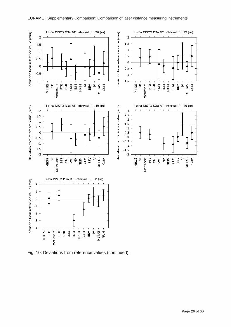
EURAMET Supplementary Comparison Comparison of laser distance measuring instruments
Page 26 of 60
Fig 10 Deviations from reference values (continued)
EURAMET Supplementary Comparison Comparison of laser distance measuring instruments
Page 27 of 60
Fig 10 Deviations from reference values (continued)
EURAMET Supplementary Comparison Comparison of laser distance measuring instruments
Page 28 of 60
Fig 10 Deviations from reference values (continued)
EU
RA
ME
T S
upplementary C
omparison C
omparison of laser distance m
easuring instruments
P
age 29 of 60
Table 8 Deviations from the reference value (given at the top of the table) and expanded uncertainties (k=196) of such deviations for BOSCH DLE 50
Table 9 Deviations from the reference value (given at the top of the table) and expanded uncertainties (k=196) of such deviations for BOSCH GLM 150
EU
RA
ME
T S
upplementary C
omparison C
omparison of laser distance m
easuring instruments
P
age 30 of 60
Table 10 Deviations from the reference value (given at the top of the table) and expanded uncertainties (k=196) of such deviations for Leica DISTO D3a BT
Table 11 Deviations from the reference value (given at the top of the table) and expanded uncertainties (k=196) of such deviations for Leica DISTO D8
EURAMET Supplementary Comparison Comparison of laser distance measuring instruments
Page 31 of 60
11 En Tables Results with En gt 1 are marked with red color in Tables below En values are calculated by Di U(Di) with Di and U(Di) as given on page 19
Table 12 BOSCH DLE50
Lab Distance (mm) 300 5000 10000 15000 20000 25000 30000 35000 40000 45000 50000
MIKES -058 017 -019 -023 035 -002 -096 SP 020 019 006 005 009 059 064 037 028 097 001
Metrosert -030 -031 -003 018 032 PTB 001 029 022 -006 011 -036 001 -023 -075 -083 001 GUM -033 -005 -018 -009 000 006 017 005 -026 -028 019 CMI -003 020 -009 004 005 -022 028 SMU 006 -049 -034 -023 -017 -057 051 039 021 INM 032 031 037 006 020 005 -079 -119 -272 -260 -269
INRIM 025 -013 000 096 CEM -032 -022 -041 -039 -004 -038 080 001 -094 -047 BEV -010 007 000 -001 008 -011 037 013 -001 008 -001 JV -019 -016 025 -055 055 060 068 163 122 060 089
METAS 038 012 -005 007 -107 004 -024 002 -070 037 -052
Table 13 BOSCH GLM150
Lab Distance (mm) 300 5000 10000 15000 20000 25000 30000 35000 40000 45000 50000
MIKES 005 -002 019 018 027 019 062 SP 003 068 029 023 051 008 015 016 -005 -001 038
Metrosert -061 -011 -022 -021 -003 PTB 066 074 062 062 034 053 047 048 047 091 064 GUM -007 -014 007 -018 000 023 020 033 014 032 038 CMI -057 -032 -030 -064 -050 -047 000 SMU 023 -024 -060 012 062 001 -003 050 047 INM -022 017 -003 002 -003 054 005 -006 016 -022 -055
INRIM 079 -052 -050 -026 -034 -042 CEM 002 002 -034 -020 -029 -077 -077 -077 -074 -104 BEV -004 -002 -007 010 -042 -042 -029 -011 -028 -022 -030 JV 003 015 040 011 -020 021 -029 -005 028 036 058
METAS -047 -020 005 002 -012 -033 -054 -065 -053 -082 -040
Table 14 Leica DISTO D3a BT
Lab Distance (mm) 300 5000 10000 15000 20000 25000 30000 35000 40000 45000 50000
MIKES 008 094 050 -011 028 051 045 SP 033 038 056 017 053 065 076 051 017 071 011
Metrosert -060 -004 -037 -014 -002 PTB 067 000 070 030 089 062 061 081 124 050 072 GUM 023 019 035 008 038 053 029 058 070 064 063 CMI -001 -004 027 -011 011 034 -033 SMU 002 -013 -019 007 -013 -055 045 -013 -042 INM 002 -039 -058 001 002 -045 -080 -051 -102 -101 -378
INRIM 070 -020 063 101 CEM -028 -004 -004 -064 003 -002 -050 -022 -093 -160 BEV -032 -019 -019 004 -011 -037 -017 -002 -025 005 012 JV 027 019 027 042 046 039 043 048 072 115 024
METAS -091 -008 -102 -098 -111 -103 -092 -080 -073 -108 -043
EURAMET Supplementary Comparison Comparison of laser distance measuring instruments
Page 32 of 60
Table 15 Leica DISTO D8
Lab Distance (mm) 300 5000 10000 15000 20000 25000 30000 35000 40000 45000 50000
MIKES 025 013 058 036 038 061 022 SP 057 026 040 016 013 016 025 017 -007 -019 007
Metrosert -021 006 -016 -043 -019 PTB 040 011 035 -005 -011 -002 -004 035 047 022 069 GUM -028 005 -025 031 039 -015 029 048 041 052 072 CMI -104 -026 -072 -057 -006 -017 -015 SMU -067 -017 -051 -026 -016 -054 -004 -001 -016 INM 021 -014 009 003 -017 -031 -010 007 029 036 041
INRIM 076 -024 -004 047 -007 083 CEM 004 -009 002 -033 -051 -059 -097 -077 -116 -134 BEV -057 -014 -051 -093 -024 -027 -021 -036 -038 -028 -041 JV 014 031 047 030 044 043 035 056 093 108 030
METAS 035 007 026 038 -013 -024 -011 -048 -089 -074 -066
12 Conclusions It was the first comparison of EDMs For most of the laboratories it was an important opportunity to validate their measurement instrumentation and procedure It allowed to become aware of potential problems and to take corrective actions in changing the procedure
For the evaluation of the reference value the weighted mean approach has been chosen although the consistency check according to procedure A of Ref [1] failed in many cases A more complicated procedure for the evaluation of the reference value was proposed which slightly changes the uncertainty of the reference value
In total there were 23 En values larger than 1 This represents 47 of the full set of 482 results It is less than the 5 of possible values being out of the expanded uncertainty of the reference value for k=2
The uncertainty of the results mainly comes from the uncertainty of the reproducibility It is difficult to distinguish between Labrsquos calibration and measurement capability
The comparison shows a global compliance with declared CMCs independently of whether some participant can have a high percentage of values not compliant with its CMC due to the influence of the artifact and the estimation of its uncertainty
13 References [1] M G Cox The evaluation of key comparison data Metrologia 39 589 ndash 595 (2002)
[2] R Thalmann EUROMET 677 ndash Steel Tape Measures Final report (2004)
[3] F Pollinger personal communication
EURAMET Supplementary Comparison Comparison of laser distance measuring instruments
Page 33 of 60
Appendix 1 Description of the measurement equipmen t as reported by the laboratories
A11 MIKES Finland
Short description of measurement bench
MIKES interferometric bench is situated in an underground laboratory with air temperature and humidity control Typically air temperature is 20 plusmn 01 degC and humidity 45 plusmn 2 RH The linear guide on the top of the concrete beam comprises two parallel round shafts with adjustable fixtures every 1 m A carriage with ball bush bearings is moved along the rail and location of it is measured with reference interferometer HP-5529A Temperature of air is measured with 6 pt100 sensors and Keithley 2010 multimetre with 4-wire resistance mode Air pressure and humidity are measured with Vaisala PTU200 Updated Edleacuten equation by Boumlnsch amp Potulski is used for calculation of refractive index of air
For EDM calibration on the other end than laser interferometer is a fixed reference plate which is adjusted perpendicular to the laser beam Next to the reference plate is an adjustable base for EDM instrument with which it can be adjusted to point parallel and coincident with measurement arm of the interferometer A target plate adjusted perpendicular to laser beam is fixed to the carriage The calibration followed Abbe principle with some millimetre uncertainty in offset adjustment
First reference interferometer is set to zero when the target plate and reference plate are in contact then EDM is positioned and adjusted in its base The rear surface of the EDM is also slightly pressed against reference surface behind it Then the readings from both instruments are collected at selected locations For this calibration there is no fine adjustment of the target position so there are typically deviations of up to few millimetres from nominal locations Results are averages of 3-4 measurements
Additional remarks
The CMC entry MIKES has for EDM calibrations is based on calibration of length scales of high quality total stations and laser trackers This type of EDMs used in this comparison are not accurate enough for truly testing of MIKES calibration measurement capability
EURAMET Supplementary Comparison Comparison of laser distance measuring instruments
Page 34 of 60
A12 SP Sweden
Short description of measurement bench
The bench consists of a simple aluminium Uminusshaped profile with polished steel pins acting as supports for the tape The bench is a little over 50 m long and works as support for the reference tape and the calibrated EDMs simultaneously
Length measurement instrument
Comparison with reference steel tape
Temperature measurement system number and location of sensors
The tape temperature is continuously registered in 6 points equally distributed along the bench The air temperature is monitored during the measurements but not used for corrections
Additional remarks
The EDM support is placed approximately 2 cm vertically above the tape No visual aid is used
EURAMET Supplementary Comparison Comparison of laser distance measuring instruments
Page 35 of 60
A13 AS Metrosert Estonia
Short description of measurement bench
The 21-m bench is located in the designated corridor-like laboratory room The lab is air-conditioned and the stability of temperature is typically plusmn05 ordmC There are three humidity and temperature sensors in room for stability and gradient monitoring
Two stainless steel rails running in parallel are made of 3-m long rods The rails lay without fixed attachment on metal supports which are mounted on concrete base The base rests on pillars made of bricks
Length measurement instrument
Laser-interferometer system Renishaw ML10 was used as length measurement instrument
Laser interferometer gets temperature humidity and pressure data from itrsquos own measurement system EC10
Additional remarks
Due to the length of the bench only measurements up to 20 m could be made Five measurement series were made with each EDM
EURAMET Supplementary Comparison Comparison of laser distance measuring instruments
Page 36 of 60
A14 PTB Germany
Short description of measurement bench
The measurements were performed on the 50 m geodetic base of the PTB The comparator consists of a 50 m rail The laboratory is equipped with a network of 21 temperature sensors spaced by 25 m along the bench As depicted in fig 1 the EDM is mounted at one end of the comparator the reflector is fixed vertically on the carriage A large retroreflector is mounted approximately 150 mm below the EDM reflector on the carriage reflecting the beam of the reference interferometer The deviation of the length due to tilting carriage (Abbe error) has been investigated along the bench by comparison of two interferometers It remains smaller than 100 microm The distance of the first position of 300 mm with respect to the back side of the EDM is determined by a gauge block of 300 mm length and a thickness of 10 mm This procedure is depicted for one of the comparison standards in figure 2
For the calibration the desired positions are programmed After the carriage reaches a measurement position the operator waits for another 30 s for the carriage to settle In control experiments the remaining movement between positioning and measurement remained smaller than 2 microm The operator then activates the measurement of the EDM reads the indicated position and writes it down The procedure is repeated for twelve times at every position the mean of the 12 measurements represents the ldquoindicated distance by the EDMrdquo All measurements of a single run at one position are performed within approximately one minute The complete measurement was repeated for four times
Length measurement instrument
The reference length is determined by a frequency-calibrated laser interferometer (Agilent 5519A) The reference interferometer is set up in Michelson geometry the signals being digitalised by a Heidenhain IK 121 card The index of refraction is determined by the external weather station of the geodetic base consisting of 21 Pt-100 temperature sensors spaced 25 m along the bench two humidity sensors (Testo 650) and two pressure sensors (Setra 370 and DPI 141) The environmental parameters are used to determine the index of refraction for the reference measurement deploying the modification of the Edleacuten equation by Boumlnsch and Potulski
EURAMET Supplementary Comparison Comparison of laser distance measuring instruments
Page 37 of 60
A15 CMI Czech Republic
Description of measurement bench
The EDMs were measured on 30 m long measuring bench equipped by laser interferometer (LI) Renishaw ML10 (pic 1 and 2) calibrated traceable to national standard of length and quantities of environmental sensors The target plate and retroreflector of the LI were fixed on a moving part of the bench and each EDM was fixed in horizontal position by clamps (pic 3) LI and EDM are placed on opposite ends of bench the Abbe offset was lt10 mm for some of them and lt50mm for all The value of LI was reset (to zero) at position corresponding to the rear of the EDM (using 3D measuring arm FARO Quantum with uncertainty about 27microm) The perpendicularities of the EDM stop as well as target plate to the beam were also checked by FARO) Each EDM was 3x replaced and aligned the measurement (reading) was repeated 6 times for each alignment and position the mean value of these 3x6 measurements is stated in tables with results The uncertainty claimed covers the statistical uncertainty of single readings Only in case of Leica D8 (the best performing EDM in this comparison) we state also the uncertainty corresponding to the mean of 6 readings in last column (this uncertainty is smaller and better illustrates our CMC)
Length measurement instrument
- Laser interferometer Renishaw - Laser 633 nm Type ML10 - Compensator EC10 - 3D measuring arm FARO Quantum - 3D measuring arm FARO Quantum
EURAMET Supplementary Comparison Comparison of laser distance measuring instruments
Page 38 of 60
A16 SMU Slovakia
Short description of measurement bench
No bench is available at the SMU the measurements are being carried out in the underground corridor of the laboratory building with length of 428 m
The 50 m steel measuring tape KINEX was used as the reference laid on the floor and pulled by the force 50 N (the same force as had been applied during its calibration at the SMU) The calibration of reference tape was done at the SMU using ULM3m Zeiss with laser interferometer Agilent 5529 B (ie per 3 m parts)
Three mercury thermometers with the resolution of 01 degC were used along the measurement path each of them laid onto the tape and located at 667 m 1990 m (instead of 20 m because of this was one of measuring points) and 333 m respectively Each of them thus corresponded approximately to one third of the measured steel tape section
Regarding the 03 m measuring point the ULM3m Zeiss length measuring machine was used with the 300 mm gauge block as the reference
Length measurement instrument
We used our own target plate being fixed perpendicularly (within uncertainty stated) to the construction equipped with nonius and the camera holder transported manually along the steel tape The second construction was fixed to the tape by such a way that zero line of the tape corresponded to the rear of EDM (within uncertainty stated)
The position of the target is read on the monitor and 20 repeated readings of the EDM data took place in each measuring point (multiples of 5 m up to 40 m)
Concerning 03 m the 300 mm gauge block was fit between the target plate and the construction with EDM The distance of the EDM rear from the target plate corresponded to the length of gauge block (within uncertainty stated)
Additional remarks
The identical measurement method was used as we use to do within our calibration service although the results reporting is different ndash we provide the regression line calculated from the measurement of irregularly distributed points and corresponding uncertainty (k = 2) in the form of [a bL] mm (ie the same coefficients for each length in the range (0 ndash 42) m)
SMU hasnrsquot got this category in CMC tables
EURAMET Supplementary Comparison Comparison of laser distance measuring instruments
Page 39 of 60
A17 INM Romania
Short description of measurement bench
Geodesic base located in the basement of the laboratory with nominal length equal to 50 m having a mobile carriage thet support both laser He-Ne retroreflector and the target of the laser distance measuring instrument in the front of geodesic base exists a support where are aligned both laser interferometer and the laser distance measuring instruments
Length measurement instrument
Laser interferometer type Hewlett Packard model 5526 A with nominal length equal to 50 m resolution 0001 mm
U = 02 microm +0510-6L
Additional remarks
During the measurements the maximum gradient of temperature was equal to 05 degC
EURAMET Supplementary Comparison Comparison of laser distance measuring instruments
Page 40 of 60
A18 INRIM Italy
Short description of measurement bench
The facility for long distance measurements is located in a corridor of the gallery devoted to dimensional metrology The structure consists in a 28 m long rail fixed to a series of pillars which rest directly on the ground released from the vibrations of floor and wall The measuring system is based on a heterodyne interferometer whose mobile arm consists of a hollow retro-reflector mounted on a structure that can run along the rail so-called carriage A photograph of the facility is presented in Fig1
The carriage is moved by a micro-step motor the motor driver receives a digital pulse and converts it into an electrical pulse to run the motor Each pulse causes a rotation of the motor shaft of one step which amounts to 11000 of a complete revolution of the shaft If the pulse frequency increases the rotation becomes continuous with a speed that is directly proportional to the pulse frequency The speed ranges between few microms up to 27 ms with a resolution of 03 microms
Since the carriage must move back and forth automatically for a distance of almost 30 m a remote control to send pulses to the motor driver was implemented It consists of two parts a radio command which allows to set some general parameters of the carriage movement such as the movement direction and mode of travel (slow or fast) and a fast command which is performed by an amplitude modulated laser beam placed at the beginning of the track oriented towards the carriage A photo detector placed above the carriage receives the modulated laser beam which is transformed into pulses to be sent to the driver of the motor The modulation of the laser beam is implemented by a LabView program that controls a digital output of the data acquisition device
Length measurement instrument
The length measurement instrument is based on a heterodyne incremental interferometer The main beam of the interferometer with frequency f1 is generated by a frequency stabilized
EURAMET Supplementary Comparison Comparison of laser distance measuring instruments
Page 41 of 60
He-Ne laser calibrated with respect to the INRIM length standard and sent to the measurement arm the second beam is a portion of the first one diffracted by an acousto-optic modulator (AOM) with frequency f2 = f1 + 80 MHz The reference detector acquires the beat note signal at 80 MHz while the measurement detector acquires a signal at 80 MHz whose phase is varied due to the displacement of the retro-reflector moving on the rail In figure 2 the optical design of the interferometer is presented
Two different measuring techniques have been implemented
1 the ldquophase measuringrdquo technique based on fringes counting with a relative uncertainty of 5middot10-7 but limited at the maximum carriage speed of 3 cms
2 the ldquoDoppler frequency measurementrdquo technique for higher carriage speed based on the measurement of the Doppler frequency shift while the carriage runs
The second technique was validated by means of the comparison with the first technique at low speed with an agreement of the order of 3middot10-6 hence the Doppler frequency method could be considered validated within 01 mm over the whole rail path with the advantage of reducing the time needed to cover long distances so it was used for the EDM comparison
In order to obtain the distance covered by the carriage according to technique 2 the Doppler frequency is measured by a commercial high-performance counter (a Pendulum CNT-90) without dead time based on time stamping then it is converted in speed and integrated over time according to the following formula
( ) ( )int minus=minus= tffn
dtn
ffdairair
λλ
2
1
2
1
where d is the distance covered by the carriage f is the frequency of the measuring signal with the carriage at rest frsquo the frequency of the measuring signal with the carriage moving λi
is the wavelength of the laser in vacuum n - air is the air refractive index and ti is the integration time The difference frsquo-f is just the Doppler frequency due to the moving carriage
The time interval measurement resolution of the instrument is 100 ps and the time base is
EURAMET Supplementary Comparison Comparison of laser distance measuring instruments
Page 42 of 60
connected to the INRIM UTC so that the measurements of the Doppler frequency and the integration time are extremely accurate The environmental parameters such as air temperature atmospheric pressure partial pressure of water were monitored during the measurement process in order to calculate the value of air refractive index according to the Edlenrsquos formula
Comparison set-up
The different technical solutions adopted for the EDMs and for the target plate positioning are discussed in this paragraph and sketched in figure 3
Fig 3 picture of the EDM and target positioning area
Target plate positioning
In order to use the provided target plate an ad-hoc mounting was manufactured at INRIM it consists in a sort of picture frame made in aluminum which slightly clamps the target folded in half and gives it the necessary stiffness to be a reproducible target The upper part of the frame is L-shaped and allows it to be fixed to the carriage structure by means of two screws The rear part of the target mounting is depicted in figure 4 The target mounting was considered necessary because of the poor stiffness and planarity of the plastic target With the aluminium frame a planarity better than 01 mm was guaranteed The target plate is placed few centimetres next to the retro-reflector and normal to the interferometer beam axis since the EDM laser should be as close and parallel as possible to the reference beam
EURAMET Supplementary Comparison Comparison of laser distance measuring instruments
Page 43 of 60
Fig 4 picture of the rear part of the target plate mounting
EDMsrsquo positioning
The EDMs are placed on a cradle-like platform which is able to adjust the inclination of the EDM along the longitudinal axis (pitch angle) The platform height allows the EDMs to be at approx the same height as the interferometer beam A crucial role was played by the stop-wall placed behind the platform since it represents the ldquozero pointrdquo for all the length measurement Hence a particular effort was devoted to align the stop-wall so that it was normal to the interferometer beam axis and parallel to the target plate
Fig 5 detail of EDMsrsquo positioning the cradle-like platform and the stop-wall are well visible
EURAMET Supplementary Comparison Comparison of laser distance measuring instruments
Page 44 of 60
Target and stop-wall alignment
In order to have the stop-wall parallel to the target plate and normal to the interferometer beam axis the following procedure has been used
1) the stop-wall and the target plate were roughly placed trying to set them parallel and normal to the rail by eye (ie within few millimeters)
2) in order to check if the target was normal to the rail one EDM was positioned on the platform the pitch and yaw angles of the EDM were adjusted by observing the position of the EDM laser spot on the target plate when the target is moved along the rail fixed position means laser beam parallel to the carriage movement Then the target was moved until the end of the rail and a thin mirror was kept in contact with it hence observing the EDM laser reflected by the mirror it was possible to adjust the target tilt acting on the screws until the laser beam is reflected back to the source
3) finally in order to check the parallelism between the stop-wall and the target a tool made by a laser pointing orthogonally to its base was used the base was leant against the stop-wall and the laser was centered on the target when the target is near then the target was moved until the end of the rail hence observing the spot of the laser on the target it was possible to adjust the stop-wall orientation
The residual misalignment errors which we were not able to eliminate were kept into account in the uncertainty budget
Measurement of the first 30 cm
Due to the geometry of our set-up it was not possible to perform the first point of measurement by means of the interferometer indeed the carriage (hence the target) is not able to go in contact with the stop-wall
Fig 6 measurement of the first 30 cm the ruler touching the stop-wall and the target and the mechanical probe (in the back) touching the carriage are visible
EURAMET Supplementary Comparison Comparison of laser distance measuring instruments
Page 45 of 60
So a ruler made of aluminum with rounded ends and nominal length equal to 30 cm was adopted to set the distance between the target plate and the stop-wall for the first point of measurement as it is shown in figure 6 The ruler whose length was measured by a CMM machine was inserted between the target and the stop-wall leaning against the latter and the carriage was carefully moved towards the stop-wall until the target lightly touched the ruler A mechanical probe that touches the carriage structure when carriage is in the ldquo30 cmrdquo position was used as a reference measurement to check the repeatability of this distance after each measurement set
Fig 7 detail of the mechanical probe touching the carriage
Environmental parameters
The environmental parameters such as air temperature atmospheric pressure and humidity were monitored during the whole measurement process in order to calculate the value of air refractive index according to the Edlenrsquos formula
Among these parameters the temperature distribution along the mobile arm of the interferometer was our main concern mainly for two reasons
1 the temperature control of the gallery was not perfectly working during the measurement period so temperature drifts had to be monitored
2 longitudinal temperature gradients due to non uniform heating and to the presence of electronic instruments were pretty high
To the purpose 14 thermometers were uniformly dislocated along the rail and automatically recorded for all the measurement period Both temporal drifts and gradients along the path have been taken in account in the uncertainty budget In any case maximum temperature differences along the rail are within 1 degC In fig 8 an extract from the acquisition file is shown
Unfortunately the air conditioning system did not work well during the measurement campaign hence the measurements were performed at a mean temperature of 209 degC
EURAMET Supplementary Comparison Comparison of laser distance measuring instruments
Page 46 of 60
Fig 8 each curve represents the temperature distribution along the rail during the measurements campaign
Carriage waving
Since the rail is not perfectly straight and the measurement laser is not coincident with the measurement beam the Abbegrave error due to waving of the target must be considered A quantitative measurement and a qualitative measurement were carried out With an electronic level placed on the carriage the straightness on the vertical plane has been mapped with a half meter resolution (the data are reported in fig 9) With a laser placed on the carriage the horizontal and vertical waving are qualitatively compared by looking at the movements of the light spot on a target fixed to the rail end As a conclusion the horizontal and vertical waving are comparable in magnitude and the peak to peak error is of the order of 300 arcseconds
Fig 9 vertical waving of the target measured by an electronic level placed on the carriage
EURAMET Supplementary Comparison Comparison of laser distance measuring instruments
Page 47 of 60
Measurement procedure
The measurements were carried out according to the following procedure
The target was set in the starting position with the procedure described above
In sequence the four EDMs are positioned on the base the horizontal and vertical tilt are adjusted and the distance measurement is recorded An additional fifth EDM (Bosh DLE 150 property of INRiM) was included in the measurement sequence Each EDM is placed on the base and gently pushed against the reference wall in such a way that the measurement laser beam starting point is the same for all EDMs Than the horizontal and vertical angles were adjusted in order to hit the central point of the target indicated with two black marks (see pictures 3 and 6) with ldquovisualrdquo alignment The measurement button is then pressed several times (typically 5) and the average reading is recorded Typical dispersion between readings is within few last digit units In case the dispersion between readings is too large the anomaly is recorded
The carriage was then moved in the next position (about 5 m) and the measurement sequence was repeated for the 5 EDMs The operation is repeated up to 25 m The 25 m measurement is than repeated again as well as all the points till the first one so that each point is measured twice each set Since the carriage movement is ldquoopen looprdquo the positioning of the carriage was not exactly in the nominal 5 m intervals For each positioning the incremental displacement is measured by the interferometer in the Doppler mode Finally the measured values were averaged in order to give a single value for each nominal position
At the end of the measurement set when the carriage is at the 30 cm position again the sum of the interferometric measurements should be very close to zero The residual value is compared with the difference between the first and the final measurements of the mechanical probe The difference must be within the uncertainty of the Doppler technique otherwise some error occurred in the measurement set that must be repeated
At the end of the session 10 complete sets of measurements recorded from the 20th to the 30th of January 2012 have been considered for this report
Additional remarks
Effect of laser pointing
During a preliminary set of measurements we noticed a strong and unexpected dependence of the measurement result on the position of the laser spot on the target Indeed since no particular instructions were given about the relative position of the laser spot on target position (except to exclude the central joint between the two halves) we decided to work relatively close to the right side of the target -closer to the interferometer beam- in order to reduce the Abbegrave error We noticed very large errors at large distances in particular of the Leica DISTO D3a (see figure 10)
EURAMET Supplementary Comparison Comparison of laser distance measuring instruments
Page 48 of 60
Fig 10 errors of each EDM In a preliminary set of measurements
We also noticed that this error was strongly dependent on the position of the spot on the target For this reason we carried out a set of measurements at the maximum length in different positions of the target from one edge to the other according to figure 11 The results are reported in table V
EDM A B C D E
Leica D3a -4 +1 0 +24 +43
+2 0 +42 +40
-1 0 +38
Leica D8 0 0 0 2 +7
0 +12 +23
table V deviations (in mm) from the length measured at point C aiming the laser spot at different positions of the target (notations as in figure 11)
We tried to find an explanation to this effect in the shape of the laser spot if the spot was
EURAMET Supplementary Comparison Comparison of laser distance measuring instruments
Page 49 of 60
particularly defocused or had high diffraction some of the energy could fall out of the target and affect the measurement result In fact the images of the spots (shown in fig 12) do not support this hypothesis Finally we decided to use the center of the (half) target for the comparison
Changing the target
In order to investigate the influence of the target on the measurements a cardboard foil (400 x 400) mm was fixed to the target mounting and a complete set of measurements was performed The results reported in figure 13 and 14 do not show any evidence of a possible dependency of the EDM measurement on the target kind
EURAMET Supplementary Comparison Comparison of laser distance measuring instruments
Page 50 of 60
Measurement at 50 m
Although we are not able to perform traceable length measurements beyond 28 m we wanted to get a sense of EDMs behaviour at longer distances So a target (represented by a rack side wall) was placed at approximately 50 m one after the other the EDMrsquos were positioned on the base and pointed towards the target The measurements were repeated then the target was replaced by the target used for the comparison and a third set of measurements were performed To our great surprise all the EDMrsquos were in good agreement (within 2 or 3 mm for each set of measurement) even those which showed errors of the order of five to ten millimeters at 25 m namely BOSCH DLE 50 and LEICA DISTO D3a Therefore each set of measurements was averaged and the deviations from the mean value are reported in figure 15
EURAMET Supplementary Comparison Comparison of laser distance measuring instruments
Page 51 of 60
Fig 15 Deviations from average value of the measurements At 50 m
EURAMET Supplementary Comparison Comparison of laser distance measuring instruments
Page 52 of 60
A19 CEM Spain
Short description of the measurement bench
To make the measurements of EDMs we have used a reference line made of adjustable supports fixed on a wall of the laboratory Each support is nominally separated five metres from the previous one so we can generate reference lengths up to fifty metres with a pitch of five metres The supports are designed to accommodate both targets and handheld EDMs Distances between supports were measured by using a total station traced to national standards The relative angles of the bases have been measured and corrected
Fig 1 - View of three consecutive supports of the 50 m baseline (left) Lab technician situating an EDM on the first support of the baseline (right)
Length measurement instrument
The baseline was calibrated by using a total station Leica TDA5005 with spherical reflector the calibration uncertainty being 02 mm for k = 2
The target is provided by the comparison The quality of the target was judged as not good due to geometrical constructive errors and the lack of rigidity and stability We measured the flatness of the target surface the distance edge-surface and the angle between them by using a 3D coordinate measuring machine The results of flatness and angle were included in the uncertainty budget and the distance EDM-target was corrected for each EDM due to each beam impinged on a different point of the target
We were not able to measure the distance 0 to 03 m because the baseline pitch is 5 meters and although we are able to measure shorter values in a different facility the target was not appropriate for our bench
EURAMET Supplementary Comparison Comparison of laser distance measuring instruments
Page 53 of 60
Fig 2 - View of an EDM on the first support of the baseline (left) A closer look showing the support adjustments and the origin plate (right)
Fig 3 - View of the comparison target on one of the supports of the baseline (left) A closer look showing the target edge against the support rigid reference (right)
Measurement method
The measurements were carried out by comparison against the known values of the calibrated baseline (metallic references on supports)
Environmental conditions were maintained within the following limits
- Temperature 20 ordmC plusmn 05 ordmC
- Humidity 45 plusmn 10
Each laser distance measuring instrument was placed at the first support of the base and aligned so that the laser beam was perpendicular to the target as indicated by the comparison protocol
For each measurement we took the average of thirty measurements It permitted us to evaluate the repeatability of the instrument
EURAMET Supplementary Comparison Comparison of laser distance measuring instruments
Page 54 of 60
A110 BEV Austria
Short description of the measurement bench
Fig 1 Carriage of tape bench View from the laser interferometer side Retroreflector mounted on the vertical plate the EDM target is mounted on the backside
Fig 2 Support for the DUT Adjustable with 2 translational and 2 rotational degrees of freedom respectively
Fig 3 Setting of the 300 mm starting position Note the rough-and-ready mounted target plate
Fig 4 Laser interferometer side of the bench The DUT is 50 m away on the other side
EURAMET Supplementary Comparison Comparison of laser distance measuring instruments
Page 55 of 60
Measurement procedure 1 The EDM is positioned with the help of a 4-axis positioning stage so that its laser beam is
coaxial with the measurement direction of the laser interferometer (in head on configuration)
2 The EDM is removed from its support The bench carriage is positioned so that the distance of the target plate from the EDM back support is 300 mm A length bar with spherical faces is used for this adjustment The laser interferometer is preset to 300 mm and the EDM is put back on its support
3 At each position 10 consecutive measurements are taken (repeatability) and the carriage is moved to the next position The carriage is manually moved under control of the laser interferometer until it is within plusmn30 microm at the correct position (Exception for the DLE 150 the target is not positioned at 10 m but at 10 m ndash 1 mm to make use of the higher resolution) The indicated (not the nominal) distance of the laser interferometer is recorded for the determination of the deviation
4 After reaching the 50 m position all points are measured in reverse order (bidirectional) Immediately after the last measurement the EDM is removed and the indication using the 300 mm length bar is checked (thus noting a possible drift of the setup)
5 Each instrument was measured 4 times according to this procedure on different days (reproducibility of bench and instrument)
Length measurement instrument
Agilent laser interferometer with long range option The bench was completed short time before performing these measurement So the characterisation was not complete and the respective measurement uncertainty of the laser interferometer is estimated rather high But anyway its contribution to the overall uncertainty can nearly be neglected
Additional remarks
The uncertainty originating from the DUT is the dominating uncertainty contribution Specifically the resolution of the two Bosch instruments (1 mm) and the repeatability are the largest contributions For the DLA 50 the pooled standard deviation of a reading at 50 m is larger than 2 mm Moreover the length dependence is not a simple function
All of the instruments show a significant deviation of the laser beam from the normal of the back (reference) face of the instrument The measured angles reach from 04deg (D3a) to 11deg (DLE 50) This leads depending on the outer dimensions of the instruments to a constant uncertainty contribution of 02 mm in our setup It must be noted that the reference faces are not well defined in most of the instruments
The reproducibility is quite different for the four instruments so only part of it originates from the setup For CMC claims we will use the standard uncertainty value of the most reproducible instrument (D3a) which amounts to 013 mm For an ideal instrument with a resolution of 01 mm and perfect repeatability we would thus have a constant expanded uncertainty of 053 mm up to 50 m
EURAMET Supplementary Comparison Comparison of laser distance measuring instruments
Page 56 of 60
A111 JV Norway
Short description of measurement bench
EDM under calibration and the reference system are aligned along a 50 m measurement bench with rails to carry the linear movement of a target plate for the EDM and a corner cube reflector for the reference system The distance between parallel axis of EDM and axis of the reference system is 130 mm Abbe error due to angle errors for the movement is smaller than 01 mm and is corrected for at each measurement point At long lengths an aperture is used approximately midway between the target plate and the EDM to avoid interfering stray light to the EDM
Alignment procedure
1) Alignment of reference system to the movement of the carriage (rails)
2) Alignment of the EDM to the movement of the carriage (rails)
3) Alignment of a plane mirror at the position of the target plate using back-reflection to the EDM output (normal incident of light on the mirror)
4) Take out the EDM and align the zero reference plate at the back of the EDM to the plane mirror
5) The mirror is replaced by the target plate and the target plate is aligned to the zero reference plate
6) Zero setting of the reference measurement system when target plate is at zero distance to the reference plate at the back of the EDM
7) Put the EDM back in position and realign it to the movement of the carriage (rails)
8) Zero setting of the EDM to the reference plate
Image 1) Image 2) Image 3) Image 4)
Image 1) Items 5) ndash 6) in alignment procedure
Fixture for HP linear interferometer is seen bottom right Part of Wyler instrument is seen to the left blue colour
Image 2) Items 7) and 8) in alignment procedure
Micrometer screws for angle alignment in two directions and linear translation for zero setting of the EDM Push button on the EDM is positioned at the tilting point of the angle adjustment table to maximize stability during measurement HP 5519 A laser head is seen to the right
Image 3) Ready to measure at selected distances from zero point the reference plate
Image 4) EDM spot size at 50 m
Length measurement instrument
- Hewlett Packard Dynamic Calibrator 5519 A (max range 80 m)
- Pressure air temperature humidity Vaisala
EURAMET Supplementary Comparison Comparison of laser distance measuring instruments
Page 57 of 60
- Digital high resolution angle measurement Wyler
I used our own target plate which is of the same type as enclosed in the artefact suitcase article number 766560 from Leica but with reduced size width x hight = 90 x 137 mm
The zero reference plate is of similar type and size
Before measurements batteries of EDMs were switched to new batteries Old batteries are switched back after calibration
For L gt 5 m an aperture of similar size as the target plate is used approximately midway between the EDM and the target plate
Additional remarks
Reports on EDM indicated values at each measurement point is the average value of n = 5 repetitions A linear model of the standard deviation for the repeatability of the EDM readings at different lengths is estimated using m = 20 repetitions at least 5 positions along the scale An estimate of the length dependent repeatability is made for each instrument
The expanded uncertainty U(95) is rounded up to the limiting resolution of 1 mm in the interval 10 m to 40 m for Bosch GLM 150
After the calibration we also estimated the angle error of the optical axis of the EDM to its back plane (back reference of EDM) Bosch DLE 50 26 mrad up measured at 50 m Bosch GLM 150 8 mrad to the left measured at 50 m Leica DISTO D3a 37 mrad down measured at 20 m Leica DISTO D8 2 mrad to the left and 4 mrad down (45 mrad total) measured at 20 m
The distance between parallel walls will be measured too large if the back plane is assumed to be normal to the optical axis of the EDM by ∆LL = (1cosα ndash 1) Bosch DLE 50 ∆LL = 340 ppm (∆L = 17 mm at L = 50 m) Bosch GLM 150 ∆LL = 32 ppm (∆L = 16 mm at L = 50 m) Leica DISTO D3a ∆LL = 7 ppm (∆L = 034 mm at L = 50 m) Leica DISTO D8 ∆LL = 10 ppm (∆L = 05 mm at L = 50 m)
EURAMET Supplementary Comparison Comparison of laser distance measuring instruments
Page 58 of 60
A112 METAS Switzerland
Short description of measurement bench (photo recom mended)
50 m bench with laser interferometer (see photo detailed description in Michel Degoumois Un Long laboratoire de mesure OFMETinfo Vol5 No 2 1998)
Length measurement instrument
HP 5529 B laser interferometer range 80 m
EURAMET Supplementary Comparison Comparison of laser distance measuring instruments
Page 59 of 60
A113 GUM Poland
Short description of measurement bench
The 50 m bench is situated in the corridor laboratory located in the basement and has its own air conditioning system with air temperature 20 plusmn 1 degC and humidity 50 plusmn 10 RH The measuring carriage is carried microscope with CCD camera and the optics associated with the interferometer The carriage is driven using belt-transmission and electrical engine with remote ndash controlled variable speed drive
The EDM was placed on the fixed adjustable plate on the other end than laser interferometer The target plate of the EDM was placed on the measuring carriage For each EDM 3 series of measurement were done Before the each measurement EDM was repositioned and aligned again
Length measurement instrument
1 Laser interferometer HP 5529A with long-range option laser head HP 5519A
2 Ambient measurement system number and location of sensors - 20 air temperature sensors type YSI with KEITHLEY multimeter they are placed very
close to axis of the laser beam - air pressure and humidity are measured with Vaisala barometer and
thermohigrometer - CO2 content was measured with analyzer made by Intelli Charge type SPN 4462
EURAMET Supplementary Comparison Comparison of laser distance measuring instruments
Page 60 of 60
Appendix 2 Corrections of reports
131 CEM Spain
CEM reported two errors in their report
1) Bosch GLM 150 EDM error for 35 m should be -08 mm instead of the indicated 08 mm
2) Leica DISTO D8 EDM error for 35 m should be -019 mm instead of the indicated 019 mm
Proposed corrections have been included in Tables 2 and 4 of the Final Report
132 AS Metrosert Estonia
AS Metrosert reported mixed up of all results for Bosch DLE 50 and Bosch GLM 150 The results and uncertainties sent for DLE 50 was results for GLM 150 and vice versa
Proposed corrections have been included in Tables 1 and 2 of the Final Report
133 INRIM Italy
Among the data reported from INRIM some anomalies were found in the measurements of BOSCH DLE 50 and LEICA DISTO D3a at distances of 20 and 25 m
After preliminary discussion on Draft A it was understood that those anomalies could be explained as a sensitivity of said instruments to the laser light that once diffused by the target is reflected by surfaces parallel to the measurement axis and detected together with the wanted signal The superimposition of the two signals can cause a ldquopullingrdquo effect leading to an overestimation of the distance being the reflected path always longer than the direct one Indeed in the INRIMrsquos set-up the target was mounted pretty close to the flat rail used for the carriage movement being likely responsible for unwanted reflections that disturbed the measurements
Since the errors reported in INRIMrsquos measurements can be ascribed to a defect of BOSCH DLE 50 and LEICA DISTO D3a andor to a lack of description of the working conditions of said instruments INRIM asked to eliminate its measurement points at 20 and 25 m of said instruments from the comparison
Proposed corrections have been included in Tables 1 and 3 of the Final Report
134 JV Norway
Justervesenet has changed the procedure and introduced two apertures instead of only one aperture (iris) which was positioned at half distance between EDM and target The reason is that the reference beam also has an aperture and it is positioned right below the beam from the EDM (130 mm distance between axes) Some diffusively reflected stray light from the EDM target might enter the aperture for the reference beam reflect at the measurement table and reach the detector of the EDM In our calibration set-up we have only seen problems at L gt 30 m We will position the first aperture at ca 5 m from the EDM and then the second aperture at ca 25 m This combination of two apertures will effectively eliminate interference of stray light from the measurement table to the EDM detector for all lengths up to 50 m
Justervesenet also increases the uncertainty component regarding repeatability reproducibility so that the expanded uncertainty increases from 14 mm to 15 mm
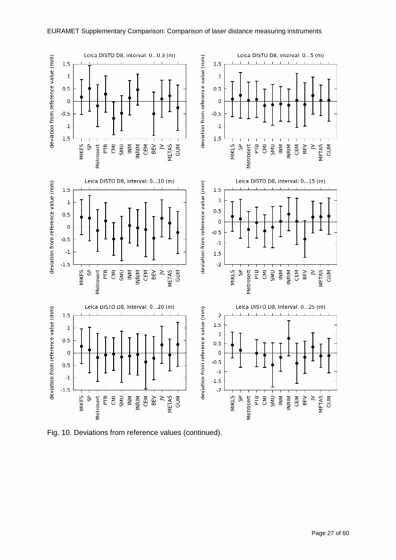
EURAMET Supplementary Comparison Comparison of laser distance measuring instruments
Page 28 of 60
Fig 10 Deviations from reference values (continued)
EU
RA
ME
T S
upplementary C
omparison C
omparison of laser distance m
easuring instruments
P
age 29 of 60
Table 8 Deviations from the reference value (given at the top of the table) and expanded uncertainties (k=196) of such deviations for BOSCH DLE 50
Table 9 Deviations from the reference value (given at the top of the table) and expanded uncertainties (k=196) of such deviations for BOSCH GLM 150
EU
RA
ME
T S
upplementary C
omparison C
omparison of laser distance m
easuring instruments
P
age 30 of 60
Table 10 Deviations from the reference value (given at the top of the table) and expanded uncertainties (k=196) of such deviations for Leica DISTO D3a BT
Table 11 Deviations from the reference value (given at the top of the table) and expanded uncertainties (k=196) of such deviations for Leica DISTO D8
EURAMET Supplementary Comparison Comparison of laser distance measuring instruments
Page 31 of 60
11 En Tables Results with En gt 1 are marked with red color in Tables below En values are calculated by Di U(Di) with Di and U(Di) as given on page 19
Table 12 BOSCH DLE50
Lab Distance (mm) 300 5000 10000 15000 20000 25000 30000 35000 40000 45000 50000
MIKES -058 017 -019 -023 035 -002 -096 SP 020 019 006 005 009 059 064 037 028 097 001
Metrosert -030 -031 -003 018 032 PTB 001 029 022 -006 011 -036 001 -023 -075 -083 001 GUM -033 -005 -018 -009 000 006 017 005 -026 -028 019 CMI -003 020 -009 004 005 -022 028 SMU 006 -049 -034 -023 -017 -057 051 039 021 INM 032 031 037 006 020 005 -079 -119 -272 -260 -269
INRIM 025 -013 000 096 CEM -032 -022 -041 -039 -004 -038 080 001 -094 -047 BEV -010 007 000 -001 008 -011 037 013 -001 008 -001 JV -019 -016 025 -055 055 060 068 163 122 060 089
METAS 038 012 -005 007 -107 004 -024 002 -070 037 -052
Table 13 BOSCH GLM150
Lab Distance (mm) 300 5000 10000 15000 20000 25000 30000 35000 40000 45000 50000
MIKES 005 -002 019 018 027 019 062 SP 003 068 029 023 051 008 015 016 -005 -001 038
Metrosert -061 -011 -022 -021 -003 PTB 066 074 062 062 034 053 047 048 047 091 064 GUM -007 -014 007 -018 000 023 020 033 014 032 038 CMI -057 -032 -030 -064 -050 -047 000 SMU 023 -024 -060 012 062 001 -003 050 047 INM -022 017 -003 002 -003 054 005 -006 016 -022 -055
INRIM 079 -052 -050 -026 -034 -042 CEM 002 002 -034 -020 -029 -077 -077 -077 -074 -104 BEV -004 -002 -007 010 -042 -042 -029 -011 -028 -022 -030 JV 003 015 040 011 -020 021 -029 -005 028 036 058
METAS -047 -020 005 002 -012 -033 -054 -065 -053 -082 -040
Table 14 Leica DISTO D3a BT
Lab Distance (mm) 300 5000 10000 15000 20000 25000 30000 35000 40000 45000 50000
MIKES 008 094 050 -011 028 051 045 SP 033 038 056 017 053 065 076 051 017 071 011
Metrosert -060 -004 -037 -014 -002 PTB 067 000 070 030 089 062 061 081 124 050 072 GUM 023 019 035 008 038 053 029 058 070 064 063 CMI -001 -004 027 -011 011 034 -033 SMU 002 -013 -019 007 -013 -055 045 -013 -042 INM 002 -039 -058 001 002 -045 -080 -051 -102 -101 -378
INRIM 070 -020 063 101 CEM -028 -004 -004 -064 003 -002 -050 -022 -093 -160 BEV -032 -019 -019 004 -011 -037 -017 -002 -025 005 012 JV 027 019 027 042 046 039 043 048 072 115 024
METAS -091 -008 -102 -098 -111 -103 -092 -080 -073 -108 -043
EURAMET Supplementary Comparison Comparison of laser distance measuring instruments
Page 32 of 60
Table 15 Leica DISTO D8
Lab Distance (mm) 300 5000 10000 15000 20000 25000 30000 35000 40000 45000 50000
MIKES 025 013 058 036 038 061 022 SP 057 026 040 016 013 016 025 017 -007 -019 007
Metrosert -021 006 -016 -043 -019 PTB 040 011 035 -005 -011 -002 -004 035 047 022 069 GUM -028 005 -025 031 039 -015 029 048 041 052 072 CMI -104 -026 -072 -057 -006 -017 -015 SMU -067 -017 -051 -026 -016 -054 -004 -001 -016 INM 021 -014 009 003 -017 -031 -010 007 029 036 041
INRIM 076 -024 -004 047 -007 083 CEM 004 -009 002 -033 -051 -059 -097 -077 -116 -134 BEV -057 -014 -051 -093 -024 -027 -021 -036 -038 -028 -041 JV 014 031 047 030 044 043 035 056 093 108 030
METAS 035 007 026 038 -013 -024 -011 -048 -089 -074 -066
12 Conclusions It was the first comparison of EDMs For most of the laboratories it was an important opportunity to validate their measurement instrumentation and procedure It allowed to become aware of potential problems and to take corrective actions in changing the procedure
For the evaluation of the reference value the weighted mean approach has been chosen although the consistency check according to procedure A of Ref [1] failed in many cases A more complicated procedure for the evaluation of the reference value was proposed which slightly changes the uncertainty of the reference value
In total there were 23 En values larger than 1 This represents 47 of the full set of 482 results It is less than the 5 of possible values being out of the expanded uncertainty of the reference value for k=2
The uncertainty of the results mainly comes from the uncertainty of the reproducibility It is difficult to distinguish between Labrsquos calibration and measurement capability
The comparison shows a global compliance with declared CMCs independently of whether some participant can have a high percentage of values not compliant with its CMC due to the influence of the artifact and the estimation of its uncertainty
13 References [1] M G Cox The evaluation of key comparison data Metrologia 39 589 ndash 595 (2002)
[2] R Thalmann EUROMET 677 ndash Steel Tape Measures Final report (2004)
[3] F Pollinger personal communication
EURAMET Supplementary Comparison Comparison of laser distance measuring instruments
Page 33 of 60
Appendix 1 Description of the measurement equipmen t as reported by the laboratories
A11 MIKES Finland
Short description of measurement bench
MIKES interferometric bench is situated in an underground laboratory with air temperature and humidity control Typically air temperature is 20 plusmn 01 degC and humidity 45 plusmn 2 RH The linear guide on the top of the concrete beam comprises two parallel round shafts with adjustable fixtures every 1 m A carriage with ball bush bearings is moved along the rail and location of it is measured with reference interferometer HP-5529A Temperature of air is measured with 6 pt100 sensors and Keithley 2010 multimetre with 4-wire resistance mode Air pressure and humidity are measured with Vaisala PTU200 Updated Edleacuten equation by Boumlnsch amp Potulski is used for calculation of refractive index of air
For EDM calibration on the other end than laser interferometer is a fixed reference plate which is adjusted perpendicular to the laser beam Next to the reference plate is an adjustable base for EDM instrument with which it can be adjusted to point parallel and coincident with measurement arm of the interferometer A target plate adjusted perpendicular to laser beam is fixed to the carriage The calibration followed Abbe principle with some millimetre uncertainty in offset adjustment
First reference interferometer is set to zero when the target plate and reference plate are in contact then EDM is positioned and adjusted in its base The rear surface of the EDM is also slightly pressed against reference surface behind it Then the readings from both instruments are collected at selected locations For this calibration there is no fine adjustment of the target position so there are typically deviations of up to few millimetres from nominal locations Results are averages of 3-4 measurements
Additional remarks
The CMC entry MIKES has for EDM calibrations is based on calibration of length scales of high quality total stations and laser trackers This type of EDMs used in this comparison are not accurate enough for truly testing of MIKES calibration measurement capability
EURAMET Supplementary Comparison Comparison of laser distance measuring instruments
Page 34 of 60
A12 SP Sweden
Short description of measurement bench
The bench consists of a simple aluminium Uminusshaped profile with polished steel pins acting as supports for the tape The bench is a little over 50 m long and works as support for the reference tape and the calibrated EDMs simultaneously
Length measurement instrument
Comparison with reference steel tape
Temperature measurement system number and location of sensors
The tape temperature is continuously registered in 6 points equally distributed along the bench The air temperature is monitored during the measurements but not used for corrections
Additional remarks
The EDM support is placed approximately 2 cm vertically above the tape No visual aid is used
EURAMET Supplementary Comparison Comparison of laser distance measuring instruments
Page 35 of 60
A13 AS Metrosert Estonia
Short description of measurement bench
The 21-m bench is located in the designated corridor-like laboratory room The lab is air-conditioned and the stability of temperature is typically plusmn05 ordmC There are three humidity and temperature sensors in room for stability and gradient monitoring
Two stainless steel rails running in parallel are made of 3-m long rods The rails lay without fixed attachment on metal supports which are mounted on concrete base The base rests on pillars made of bricks
Length measurement instrument
Laser-interferometer system Renishaw ML10 was used as length measurement instrument
Laser interferometer gets temperature humidity and pressure data from itrsquos own measurement system EC10
Additional remarks
Due to the length of the bench only measurements up to 20 m could be made Five measurement series were made with each EDM
EURAMET Supplementary Comparison Comparison of laser distance measuring instruments
Page 36 of 60
A14 PTB Germany
Short description of measurement bench
The measurements were performed on the 50 m geodetic base of the PTB The comparator consists of a 50 m rail The laboratory is equipped with a network of 21 temperature sensors spaced by 25 m along the bench As depicted in fig 1 the EDM is mounted at one end of the comparator the reflector is fixed vertically on the carriage A large retroreflector is mounted approximately 150 mm below the EDM reflector on the carriage reflecting the beam of the reference interferometer The deviation of the length due to tilting carriage (Abbe error) has been investigated along the bench by comparison of two interferometers It remains smaller than 100 microm The distance of the first position of 300 mm with respect to the back side of the EDM is determined by a gauge block of 300 mm length and a thickness of 10 mm This procedure is depicted for one of the comparison standards in figure 2
For the calibration the desired positions are programmed After the carriage reaches a measurement position the operator waits for another 30 s for the carriage to settle In control experiments the remaining movement between positioning and measurement remained smaller than 2 microm The operator then activates the measurement of the EDM reads the indicated position and writes it down The procedure is repeated for twelve times at every position the mean of the 12 measurements represents the ldquoindicated distance by the EDMrdquo All measurements of a single run at one position are performed within approximately one minute The complete measurement was repeated for four times
Length measurement instrument
The reference length is determined by a frequency-calibrated laser interferometer (Agilent 5519A) The reference interferometer is set up in Michelson geometry the signals being digitalised by a Heidenhain IK 121 card The index of refraction is determined by the external weather station of the geodetic base consisting of 21 Pt-100 temperature sensors spaced 25 m along the bench two humidity sensors (Testo 650) and two pressure sensors (Setra 370 and DPI 141) The environmental parameters are used to determine the index of refraction for the reference measurement deploying the modification of the Edleacuten equation by Boumlnsch and Potulski
EURAMET Supplementary Comparison Comparison of laser distance measuring instruments
Page 37 of 60
A15 CMI Czech Republic
Description of measurement bench
The EDMs were measured on 30 m long measuring bench equipped by laser interferometer (LI) Renishaw ML10 (pic 1 and 2) calibrated traceable to national standard of length and quantities of environmental sensors The target plate and retroreflector of the LI were fixed on a moving part of the bench and each EDM was fixed in horizontal position by clamps (pic 3) LI and EDM are placed on opposite ends of bench the Abbe offset was lt10 mm for some of them and lt50mm for all The value of LI was reset (to zero) at position corresponding to the rear of the EDM (using 3D measuring arm FARO Quantum with uncertainty about 27microm) The perpendicularities of the EDM stop as well as target plate to the beam were also checked by FARO) Each EDM was 3x replaced and aligned the measurement (reading) was repeated 6 times for each alignment and position the mean value of these 3x6 measurements is stated in tables with results The uncertainty claimed covers the statistical uncertainty of single readings Only in case of Leica D8 (the best performing EDM in this comparison) we state also the uncertainty corresponding to the mean of 6 readings in last column (this uncertainty is smaller and better illustrates our CMC)
Length measurement instrument
- Laser interferometer Renishaw - Laser 633 nm Type ML10 - Compensator EC10 - 3D measuring arm FARO Quantum - 3D measuring arm FARO Quantum
EURAMET Supplementary Comparison Comparison of laser distance measuring instruments
Page 38 of 60
A16 SMU Slovakia
Short description of measurement bench
No bench is available at the SMU the measurements are being carried out in the underground corridor of the laboratory building with length of 428 m
The 50 m steel measuring tape KINEX was used as the reference laid on the floor and pulled by the force 50 N (the same force as had been applied during its calibration at the SMU) The calibration of reference tape was done at the SMU using ULM3m Zeiss with laser interferometer Agilent 5529 B (ie per 3 m parts)
Three mercury thermometers with the resolution of 01 degC were used along the measurement path each of them laid onto the tape and located at 667 m 1990 m (instead of 20 m because of this was one of measuring points) and 333 m respectively Each of them thus corresponded approximately to one third of the measured steel tape section
Regarding the 03 m measuring point the ULM3m Zeiss length measuring machine was used with the 300 mm gauge block as the reference
Length measurement instrument
We used our own target plate being fixed perpendicularly (within uncertainty stated) to the construction equipped with nonius and the camera holder transported manually along the steel tape The second construction was fixed to the tape by such a way that zero line of the tape corresponded to the rear of EDM (within uncertainty stated)
The position of the target is read on the monitor and 20 repeated readings of the EDM data took place in each measuring point (multiples of 5 m up to 40 m)
Concerning 03 m the 300 mm gauge block was fit between the target plate and the construction with EDM The distance of the EDM rear from the target plate corresponded to the length of gauge block (within uncertainty stated)
Additional remarks
The identical measurement method was used as we use to do within our calibration service although the results reporting is different ndash we provide the regression line calculated from the measurement of irregularly distributed points and corresponding uncertainty (k = 2) in the form of [a bL] mm (ie the same coefficients for each length in the range (0 ndash 42) m)
SMU hasnrsquot got this category in CMC tables
EURAMET Supplementary Comparison Comparison of laser distance measuring instruments
Page 39 of 60
A17 INM Romania
Short description of measurement bench
Geodesic base located in the basement of the laboratory with nominal length equal to 50 m having a mobile carriage thet support both laser He-Ne retroreflector and the target of the laser distance measuring instrument in the front of geodesic base exists a support where are aligned both laser interferometer and the laser distance measuring instruments
Length measurement instrument
Laser interferometer type Hewlett Packard model 5526 A with nominal length equal to 50 m resolution 0001 mm
U = 02 microm +0510-6L
Additional remarks
During the measurements the maximum gradient of temperature was equal to 05 degC
EURAMET Supplementary Comparison Comparison of laser distance measuring instruments
Page 40 of 60
A18 INRIM Italy
Short description of measurement bench
The facility for long distance measurements is located in a corridor of the gallery devoted to dimensional metrology The structure consists in a 28 m long rail fixed to a series of pillars which rest directly on the ground released from the vibrations of floor and wall The measuring system is based on a heterodyne interferometer whose mobile arm consists of a hollow retro-reflector mounted on a structure that can run along the rail so-called carriage A photograph of the facility is presented in Fig1
The carriage is moved by a micro-step motor the motor driver receives a digital pulse and converts it into an electrical pulse to run the motor Each pulse causes a rotation of the motor shaft of one step which amounts to 11000 of a complete revolution of the shaft If the pulse frequency increases the rotation becomes continuous with a speed that is directly proportional to the pulse frequency The speed ranges between few microms up to 27 ms with a resolution of 03 microms
Since the carriage must move back and forth automatically for a distance of almost 30 m a remote control to send pulses to the motor driver was implemented It consists of two parts a radio command which allows to set some general parameters of the carriage movement such as the movement direction and mode of travel (slow or fast) and a fast command which is performed by an amplitude modulated laser beam placed at the beginning of the track oriented towards the carriage A photo detector placed above the carriage receives the modulated laser beam which is transformed into pulses to be sent to the driver of the motor The modulation of the laser beam is implemented by a LabView program that controls a digital output of the data acquisition device
Length measurement instrument
The length measurement instrument is based on a heterodyne incremental interferometer The main beam of the interferometer with frequency f1 is generated by a frequency stabilized
EURAMET Supplementary Comparison Comparison of laser distance measuring instruments
Page 41 of 60
He-Ne laser calibrated with respect to the INRIM length standard and sent to the measurement arm the second beam is a portion of the first one diffracted by an acousto-optic modulator (AOM) with frequency f2 = f1 + 80 MHz The reference detector acquires the beat note signal at 80 MHz while the measurement detector acquires a signal at 80 MHz whose phase is varied due to the displacement of the retro-reflector moving on the rail In figure 2 the optical design of the interferometer is presented
Two different measuring techniques have been implemented
1 the ldquophase measuringrdquo technique based on fringes counting with a relative uncertainty of 5middot10-7 but limited at the maximum carriage speed of 3 cms
2 the ldquoDoppler frequency measurementrdquo technique for higher carriage speed based on the measurement of the Doppler frequency shift while the carriage runs
The second technique was validated by means of the comparison with the first technique at low speed with an agreement of the order of 3middot10-6 hence the Doppler frequency method could be considered validated within 01 mm over the whole rail path with the advantage of reducing the time needed to cover long distances so it was used for the EDM comparison
In order to obtain the distance covered by the carriage according to technique 2 the Doppler frequency is measured by a commercial high-performance counter (a Pendulum CNT-90) without dead time based on time stamping then it is converted in speed and integrated over time according to the following formula
( ) ( )int minus=minus= tffn
dtn
ffdairair
λλ
2
1
2
1
where d is the distance covered by the carriage f is the frequency of the measuring signal with the carriage at rest frsquo the frequency of the measuring signal with the carriage moving λi
is the wavelength of the laser in vacuum n - air is the air refractive index and ti is the integration time The difference frsquo-f is just the Doppler frequency due to the moving carriage
The time interval measurement resolution of the instrument is 100 ps and the time base is
EURAMET Supplementary Comparison Comparison of laser distance measuring instruments
Page 42 of 60
connected to the INRIM UTC so that the measurements of the Doppler frequency and the integration time are extremely accurate The environmental parameters such as air temperature atmospheric pressure partial pressure of water were monitored during the measurement process in order to calculate the value of air refractive index according to the Edlenrsquos formula
Comparison set-up
The different technical solutions adopted for the EDMs and for the target plate positioning are discussed in this paragraph and sketched in figure 3
Fig 3 picture of the EDM and target positioning area
Target plate positioning
In order to use the provided target plate an ad-hoc mounting was manufactured at INRIM it consists in a sort of picture frame made in aluminum which slightly clamps the target folded in half and gives it the necessary stiffness to be a reproducible target The upper part of the frame is L-shaped and allows it to be fixed to the carriage structure by means of two screws The rear part of the target mounting is depicted in figure 4 The target mounting was considered necessary because of the poor stiffness and planarity of the plastic target With the aluminium frame a planarity better than 01 mm was guaranteed The target plate is placed few centimetres next to the retro-reflector and normal to the interferometer beam axis since the EDM laser should be as close and parallel as possible to the reference beam
EURAMET Supplementary Comparison Comparison of laser distance measuring instruments
Page 43 of 60
Fig 4 picture of the rear part of the target plate mounting
EDMsrsquo positioning
The EDMs are placed on a cradle-like platform which is able to adjust the inclination of the EDM along the longitudinal axis (pitch angle) The platform height allows the EDMs to be at approx the same height as the interferometer beam A crucial role was played by the stop-wall placed behind the platform since it represents the ldquozero pointrdquo for all the length measurement Hence a particular effort was devoted to align the stop-wall so that it was normal to the interferometer beam axis and parallel to the target plate
Fig 5 detail of EDMsrsquo positioning the cradle-like platform and the stop-wall are well visible
EURAMET Supplementary Comparison Comparison of laser distance measuring instruments
Page 44 of 60
Target and stop-wall alignment
In order to have the stop-wall parallel to the target plate and normal to the interferometer beam axis the following procedure has been used
1) the stop-wall and the target plate were roughly placed trying to set them parallel and normal to the rail by eye (ie within few millimeters)
2) in order to check if the target was normal to the rail one EDM was positioned on the platform the pitch and yaw angles of the EDM were adjusted by observing the position of the EDM laser spot on the target plate when the target is moved along the rail fixed position means laser beam parallel to the carriage movement Then the target was moved until the end of the rail and a thin mirror was kept in contact with it hence observing the EDM laser reflected by the mirror it was possible to adjust the target tilt acting on the screws until the laser beam is reflected back to the source
3) finally in order to check the parallelism between the stop-wall and the target a tool made by a laser pointing orthogonally to its base was used the base was leant against the stop-wall and the laser was centered on the target when the target is near then the target was moved until the end of the rail hence observing the spot of the laser on the target it was possible to adjust the stop-wall orientation
The residual misalignment errors which we were not able to eliminate were kept into account in the uncertainty budget
Measurement of the first 30 cm
Due to the geometry of our set-up it was not possible to perform the first point of measurement by means of the interferometer indeed the carriage (hence the target) is not able to go in contact with the stop-wall
Fig 6 measurement of the first 30 cm the ruler touching the stop-wall and the target and the mechanical probe (in the back) touching the carriage are visible
EURAMET Supplementary Comparison Comparison of laser distance measuring instruments
Page 45 of 60
So a ruler made of aluminum with rounded ends and nominal length equal to 30 cm was adopted to set the distance between the target plate and the stop-wall for the first point of measurement as it is shown in figure 6 The ruler whose length was measured by a CMM machine was inserted between the target and the stop-wall leaning against the latter and the carriage was carefully moved towards the stop-wall until the target lightly touched the ruler A mechanical probe that touches the carriage structure when carriage is in the ldquo30 cmrdquo position was used as a reference measurement to check the repeatability of this distance after each measurement set
Fig 7 detail of the mechanical probe touching the carriage
Environmental parameters
The environmental parameters such as air temperature atmospheric pressure and humidity were monitored during the whole measurement process in order to calculate the value of air refractive index according to the Edlenrsquos formula
Among these parameters the temperature distribution along the mobile arm of the interferometer was our main concern mainly for two reasons
1 the temperature control of the gallery was not perfectly working during the measurement period so temperature drifts had to be monitored
2 longitudinal temperature gradients due to non uniform heating and to the presence of electronic instruments were pretty high
To the purpose 14 thermometers were uniformly dislocated along the rail and automatically recorded for all the measurement period Both temporal drifts and gradients along the path have been taken in account in the uncertainty budget In any case maximum temperature differences along the rail are within 1 degC In fig 8 an extract from the acquisition file is shown
Unfortunately the air conditioning system did not work well during the measurement campaign hence the measurements were performed at a mean temperature of 209 degC
EURAMET Supplementary Comparison Comparison of laser distance measuring instruments
Page 46 of 60
Fig 8 each curve represents the temperature distribution along the rail during the measurements campaign
Carriage waving
Since the rail is not perfectly straight and the measurement laser is not coincident with the measurement beam the Abbegrave error due to waving of the target must be considered A quantitative measurement and a qualitative measurement were carried out With an electronic level placed on the carriage the straightness on the vertical plane has been mapped with a half meter resolution (the data are reported in fig 9) With a laser placed on the carriage the horizontal and vertical waving are qualitatively compared by looking at the movements of the light spot on a target fixed to the rail end As a conclusion the horizontal and vertical waving are comparable in magnitude and the peak to peak error is of the order of 300 arcseconds
Fig 9 vertical waving of the target measured by an electronic level placed on the carriage
EURAMET Supplementary Comparison Comparison of laser distance measuring instruments
Page 47 of 60
Measurement procedure
The measurements were carried out according to the following procedure
The target was set in the starting position with the procedure described above
In sequence the four EDMs are positioned on the base the horizontal and vertical tilt are adjusted and the distance measurement is recorded An additional fifth EDM (Bosh DLE 150 property of INRiM) was included in the measurement sequence Each EDM is placed on the base and gently pushed against the reference wall in such a way that the measurement laser beam starting point is the same for all EDMs Than the horizontal and vertical angles were adjusted in order to hit the central point of the target indicated with two black marks (see pictures 3 and 6) with ldquovisualrdquo alignment The measurement button is then pressed several times (typically 5) and the average reading is recorded Typical dispersion between readings is within few last digit units In case the dispersion between readings is too large the anomaly is recorded
The carriage was then moved in the next position (about 5 m) and the measurement sequence was repeated for the 5 EDMs The operation is repeated up to 25 m The 25 m measurement is than repeated again as well as all the points till the first one so that each point is measured twice each set Since the carriage movement is ldquoopen looprdquo the positioning of the carriage was not exactly in the nominal 5 m intervals For each positioning the incremental displacement is measured by the interferometer in the Doppler mode Finally the measured values were averaged in order to give a single value for each nominal position
At the end of the measurement set when the carriage is at the 30 cm position again the sum of the interferometric measurements should be very close to zero The residual value is compared with the difference between the first and the final measurements of the mechanical probe The difference must be within the uncertainty of the Doppler technique otherwise some error occurred in the measurement set that must be repeated
At the end of the session 10 complete sets of measurements recorded from the 20th to the 30th of January 2012 have been considered for this report
Additional remarks
Effect of laser pointing
During a preliminary set of measurements we noticed a strong and unexpected dependence of the measurement result on the position of the laser spot on the target Indeed since no particular instructions were given about the relative position of the laser spot on target position (except to exclude the central joint between the two halves) we decided to work relatively close to the right side of the target -closer to the interferometer beam- in order to reduce the Abbegrave error We noticed very large errors at large distances in particular of the Leica DISTO D3a (see figure 10)
EURAMET Supplementary Comparison Comparison of laser distance measuring instruments
Page 48 of 60
Fig 10 errors of each EDM In a preliminary set of measurements
We also noticed that this error was strongly dependent on the position of the spot on the target For this reason we carried out a set of measurements at the maximum length in different positions of the target from one edge to the other according to figure 11 The results are reported in table V
EDM A B C D E
Leica D3a -4 +1 0 +24 +43
+2 0 +42 +40
-1 0 +38
Leica D8 0 0 0 2 +7
0 +12 +23
table V deviations (in mm) from the length measured at point C aiming the laser spot at different positions of the target (notations as in figure 11)
We tried to find an explanation to this effect in the shape of the laser spot if the spot was
EURAMET Supplementary Comparison Comparison of laser distance measuring instruments
Page 49 of 60
particularly defocused or had high diffraction some of the energy could fall out of the target and affect the measurement result In fact the images of the spots (shown in fig 12) do not support this hypothesis Finally we decided to use the center of the (half) target for the comparison
Changing the target
In order to investigate the influence of the target on the measurements a cardboard foil (400 x 400) mm was fixed to the target mounting and a complete set of measurements was performed The results reported in figure 13 and 14 do not show any evidence of a possible dependency of the EDM measurement on the target kind
EURAMET Supplementary Comparison Comparison of laser distance measuring instruments
Page 50 of 60
Measurement at 50 m
Although we are not able to perform traceable length measurements beyond 28 m we wanted to get a sense of EDMs behaviour at longer distances So a target (represented by a rack side wall) was placed at approximately 50 m one after the other the EDMrsquos were positioned on the base and pointed towards the target The measurements were repeated then the target was replaced by the target used for the comparison and a third set of measurements were performed To our great surprise all the EDMrsquos were in good agreement (within 2 or 3 mm for each set of measurement) even those which showed errors of the order of five to ten millimeters at 25 m namely BOSCH DLE 50 and LEICA DISTO D3a Therefore each set of measurements was averaged and the deviations from the mean value are reported in figure 15
EURAMET Supplementary Comparison Comparison of laser distance measuring instruments
Page 51 of 60
Fig 15 Deviations from average value of the measurements At 50 m
EURAMET Supplementary Comparison Comparison of laser distance measuring instruments
Page 52 of 60
A19 CEM Spain
Short description of the measurement bench
To make the measurements of EDMs we have used a reference line made of adjustable supports fixed on a wall of the laboratory Each support is nominally separated five metres from the previous one so we can generate reference lengths up to fifty metres with a pitch of five metres The supports are designed to accommodate both targets and handheld EDMs Distances between supports were measured by using a total station traced to national standards The relative angles of the bases have been measured and corrected
Fig 1 - View of three consecutive supports of the 50 m baseline (left) Lab technician situating an EDM on the first support of the baseline (right)
Length measurement instrument
The baseline was calibrated by using a total station Leica TDA5005 with spherical reflector the calibration uncertainty being 02 mm for k = 2
The target is provided by the comparison The quality of the target was judged as not good due to geometrical constructive errors and the lack of rigidity and stability We measured the flatness of the target surface the distance edge-surface and the angle between them by using a 3D coordinate measuring machine The results of flatness and angle were included in the uncertainty budget and the distance EDM-target was corrected for each EDM due to each beam impinged on a different point of the target
We were not able to measure the distance 0 to 03 m because the baseline pitch is 5 meters and although we are able to measure shorter values in a different facility the target was not appropriate for our bench
EURAMET Supplementary Comparison Comparison of laser distance measuring instruments
Page 53 of 60
Fig 2 - View of an EDM on the first support of the baseline (left) A closer look showing the support adjustments and the origin plate (right)
Fig 3 - View of the comparison target on one of the supports of the baseline (left) A closer look showing the target edge against the support rigid reference (right)
Measurement method
The measurements were carried out by comparison against the known values of the calibrated baseline (metallic references on supports)
Environmental conditions were maintained within the following limits
- Temperature 20 ordmC plusmn 05 ordmC
- Humidity 45 plusmn 10
Each laser distance measuring instrument was placed at the first support of the base and aligned so that the laser beam was perpendicular to the target as indicated by the comparison protocol
For each measurement we took the average of thirty measurements It permitted us to evaluate the repeatability of the instrument
EURAMET Supplementary Comparison Comparison of laser distance measuring instruments
Page 54 of 60
A110 BEV Austria
Short description of the measurement bench
Fig 1 Carriage of tape bench View from the laser interferometer side Retroreflector mounted on the vertical plate the EDM target is mounted on the backside
Fig 2 Support for the DUT Adjustable with 2 translational and 2 rotational degrees of freedom respectively
Fig 3 Setting of the 300 mm starting position Note the rough-and-ready mounted target plate
Fig 4 Laser interferometer side of the bench The DUT is 50 m away on the other side
EURAMET Supplementary Comparison Comparison of laser distance measuring instruments
Page 55 of 60
Measurement procedure 1 The EDM is positioned with the help of a 4-axis positioning stage so that its laser beam is
coaxial with the measurement direction of the laser interferometer (in head on configuration)
2 The EDM is removed from its support The bench carriage is positioned so that the distance of the target plate from the EDM back support is 300 mm A length bar with spherical faces is used for this adjustment The laser interferometer is preset to 300 mm and the EDM is put back on its support
3 At each position 10 consecutive measurements are taken (repeatability) and the carriage is moved to the next position The carriage is manually moved under control of the laser interferometer until it is within plusmn30 microm at the correct position (Exception for the DLE 150 the target is not positioned at 10 m but at 10 m ndash 1 mm to make use of the higher resolution) The indicated (not the nominal) distance of the laser interferometer is recorded for the determination of the deviation
4 After reaching the 50 m position all points are measured in reverse order (bidirectional) Immediately after the last measurement the EDM is removed and the indication using the 300 mm length bar is checked (thus noting a possible drift of the setup)
5 Each instrument was measured 4 times according to this procedure on different days (reproducibility of bench and instrument)
Length measurement instrument
Agilent laser interferometer with long range option The bench was completed short time before performing these measurement So the characterisation was not complete and the respective measurement uncertainty of the laser interferometer is estimated rather high But anyway its contribution to the overall uncertainty can nearly be neglected
Additional remarks
The uncertainty originating from the DUT is the dominating uncertainty contribution Specifically the resolution of the two Bosch instruments (1 mm) and the repeatability are the largest contributions For the DLA 50 the pooled standard deviation of a reading at 50 m is larger than 2 mm Moreover the length dependence is not a simple function
All of the instruments show a significant deviation of the laser beam from the normal of the back (reference) face of the instrument The measured angles reach from 04deg (D3a) to 11deg (DLE 50) This leads depending on the outer dimensions of the instruments to a constant uncertainty contribution of 02 mm in our setup It must be noted that the reference faces are not well defined in most of the instruments
The reproducibility is quite different for the four instruments so only part of it originates from the setup For CMC claims we will use the standard uncertainty value of the most reproducible instrument (D3a) which amounts to 013 mm For an ideal instrument with a resolution of 01 mm and perfect repeatability we would thus have a constant expanded uncertainty of 053 mm up to 50 m
EURAMET Supplementary Comparison Comparison of laser distance measuring instruments
Page 56 of 60
A111 JV Norway
Short description of measurement bench
EDM under calibration and the reference system are aligned along a 50 m measurement bench with rails to carry the linear movement of a target plate for the EDM and a corner cube reflector for the reference system The distance between parallel axis of EDM and axis of the reference system is 130 mm Abbe error due to angle errors for the movement is smaller than 01 mm and is corrected for at each measurement point At long lengths an aperture is used approximately midway between the target plate and the EDM to avoid interfering stray light to the EDM
Alignment procedure
1) Alignment of reference system to the movement of the carriage (rails)
2) Alignment of the EDM to the movement of the carriage (rails)
3) Alignment of a plane mirror at the position of the target plate using back-reflection to the EDM output (normal incident of light on the mirror)
4) Take out the EDM and align the zero reference plate at the back of the EDM to the plane mirror
5) The mirror is replaced by the target plate and the target plate is aligned to the zero reference plate
6) Zero setting of the reference measurement system when target plate is at zero distance to the reference plate at the back of the EDM
7) Put the EDM back in position and realign it to the movement of the carriage (rails)
8) Zero setting of the EDM to the reference plate
Image 1) Image 2) Image 3) Image 4)
Image 1) Items 5) ndash 6) in alignment procedure
Fixture for HP linear interferometer is seen bottom right Part of Wyler instrument is seen to the left blue colour
Image 2) Items 7) and 8) in alignment procedure
Micrometer screws for angle alignment in two directions and linear translation for zero setting of the EDM Push button on the EDM is positioned at the tilting point of the angle adjustment table to maximize stability during measurement HP 5519 A laser head is seen to the right
Image 3) Ready to measure at selected distances from zero point the reference plate
Image 4) EDM spot size at 50 m
Length measurement instrument
- Hewlett Packard Dynamic Calibrator 5519 A (max range 80 m)
- Pressure air temperature humidity Vaisala
EURAMET Supplementary Comparison Comparison of laser distance measuring instruments
Page 57 of 60
- Digital high resolution angle measurement Wyler
I used our own target plate which is of the same type as enclosed in the artefact suitcase article number 766560 from Leica but with reduced size width x hight = 90 x 137 mm
The zero reference plate is of similar type and size
Before measurements batteries of EDMs were switched to new batteries Old batteries are switched back after calibration
For L gt 5 m an aperture of similar size as the target plate is used approximately midway between the EDM and the target plate
Additional remarks
Reports on EDM indicated values at each measurement point is the average value of n = 5 repetitions A linear model of the standard deviation for the repeatability of the EDM readings at different lengths is estimated using m = 20 repetitions at least 5 positions along the scale An estimate of the length dependent repeatability is made for each instrument
The expanded uncertainty U(95) is rounded up to the limiting resolution of 1 mm in the interval 10 m to 40 m for Bosch GLM 150
After the calibration we also estimated the angle error of the optical axis of the EDM to its back plane (back reference of EDM) Bosch DLE 50 26 mrad up measured at 50 m Bosch GLM 150 8 mrad to the left measured at 50 m Leica DISTO D3a 37 mrad down measured at 20 m Leica DISTO D8 2 mrad to the left and 4 mrad down (45 mrad total) measured at 20 m
The distance between parallel walls will be measured too large if the back plane is assumed to be normal to the optical axis of the EDM by ∆LL = (1cosα ndash 1) Bosch DLE 50 ∆LL = 340 ppm (∆L = 17 mm at L = 50 m) Bosch GLM 150 ∆LL = 32 ppm (∆L = 16 mm at L = 50 m) Leica DISTO D3a ∆LL = 7 ppm (∆L = 034 mm at L = 50 m) Leica DISTO D8 ∆LL = 10 ppm (∆L = 05 mm at L = 50 m)
EURAMET Supplementary Comparison Comparison of laser distance measuring instruments
Page 58 of 60
A112 METAS Switzerland
Short description of measurement bench (photo recom mended)
50 m bench with laser interferometer (see photo detailed description in Michel Degoumois Un Long laboratoire de mesure OFMETinfo Vol5 No 2 1998)
Length measurement instrument
HP 5529 B laser interferometer range 80 m
EURAMET Supplementary Comparison Comparison of laser distance measuring instruments
Page 59 of 60
A113 GUM Poland
Short description of measurement bench
The 50 m bench is situated in the corridor laboratory located in the basement and has its own air conditioning system with air temperature 20 plusmn 1 degC and humidity 50 plusmn 10 RH The measuring carriage is carried microscope with CCD camera and the optics associated with the interferometer The carriage is driven using belt-transmission and electrical engine with remote ndash controlled variable speed drive
The EDM was placed on the fixed adjustable plate on the other end than laser interferometer The target plate of the EDM was placed on the measuring carriage For each EDM 3 series of measurement were done Before the each measurement EDM was repositioned and aligned again
Length measurement instrument
1 Laser interferometer HP 5529A with long-range option laser head HP 5519A
2 Ambient measurement system number and location of sensors - 20 air temperature sensors type YSI with KEITHLEY multimeter they are placed very
close to axis of the laser beam - air pressure and humidity are measured with Vaisala barometer and
thermohigrometer - CO2 content was measured with analyzer made by Intelli Charge type SPN 4462
EURAMET Supplementary Comparison Comparison of laser distance measuring instruments
Page 60 of 60
Appendix 2 Corrections of reports
131 CEM Spain
CEM reported two errors in their report
1) Bosch GLM 150 EDM error for 35 m should be -08 mm instead of the indicated 08 mm
2) Leica DISTO D8 EDM error for 35 m should be -019 mm instead of the indicated 019 mm
Proposed corrections have been included in Tables 2 and 4 of the Final Report
132 AS Metrosert Estonia
AS Metrosert reported mixed up of all results for Bosch DLE 50 and Bosch GLM 150 The results and uncertainties sent for DLE 50 was results for GLM 150 and vice versa
Proposed corrections have been included in Tables 1 and 2 of the Final Report
133 INRIM Italy
Among the data reported from INRIM some anomalies were found in the measurements of BOSCH DLE 50 and LEICA DISTO D3a at distances of 20 and 25 m
After preliminary discussion on Draft A it was understood that those anomalies could be explained as a sensitivity of said instruments to the laser light that once diffused by the target is reflected by surfaces parallel to the measurement axis and detected together with the wanted signal The superimposition of the two signals can cause a ldquopullingrdquo effect leading to an overestimation of the distance being the reflected path always longer than the direct one Indeed in the INRIMrsquos set-up the target was mounted pretty close to the flat rail used for the carriage movement being likely responsible for unwanted reflections that disturbed the measurements
Since the errors reported in INRIMrsquos measurements can be ascribed to a defect of BOSCH DLE 50 and LEICA DISTO D3a andor to a lack of description of the working conditions of said instruments INRIM asked to eliminate its measurement points at 20 and 25 m of said instruments from the comparison
Proposed corrections have been included in Tables 1 and 3 of the Final Report
134 JV Norway
Justervesenet has changed the procedure and introduced two apertures instead of only one aperture (iris) which was positioned at half distance between EDM and target The reason is that the reference beam also has an aperture and it is positioned right below the beam from the EDM (130 mm distance between axes) Some diffusively reflected stray light from the EDM target might enter the aperture for the reference beam reflect at the measurement table and reach the detector of the EDM In our calibration set-up we have only seen problems at L gt 30 m We will position the first aperture at ca 5 m from the EDM and then the second aperture at ca 25 m This combination of two apertures will effectively eliminate interference of stray light from the measurement table to the EDM detector for all lengths up to 50 m
Justervesenet also increases the uncertainty component regarding repeatability reproducibility so that the expanded uncertainty increases from 14 mm to 15 mm
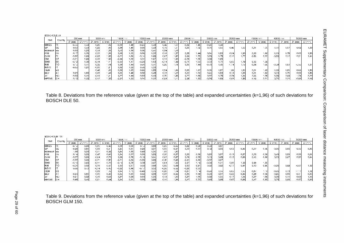
EU
RA
ME
T S
upplementary C
omparison C
omparison of laser distance m
easuring instruments
P
age 29 of 60
Table 8 Deviations from the reference value (given at the top of the table) and expanded uncertainties (k=196) of such deviations for BOSCH DLE 50
Table 9 Deviations from the reference value (given at the top of the table) and expanded uncertainties (k=196) of such deviations for BOSCH GLM 150
EU
RA
ME
T S
upplementary C
omparison C
omparison of laser distance m
easuring instruments
P
age 30 of 60
Table 10 Deviations from the reference value (given at the top of the table) and expanded uncertainties (k=196) of such deviations for Leica DISTO D3a BT
Table 11 Deviations from the reference value (given at the top of the table) and expanded uncertainties (k=196) of such deviations for Leica DISTO D8
EURAMET Supplementary Comparison Comparison of laser distance measuring instruments
Page 31 of 60
11 En Tables Results with En gt 1 are marked with red color in Tables below En values are calculated by Di U(Di) with Di and U(Di) as given on page 19
Table 12 BOSCH DLE50
Lab Distance (mm) 300 5000 10000 15000 20000 25000 30000 35000 40000 45000 50000
MIKES -058 017 -019 -023 035 -002 -096 SP 020 019 006 005 009 059 064 037 028 097 001
Metrosert -030 -031 -003 018 032 PTB 001 029 022 -006 011 -036 001 -023 -075 -083 001 GUM -033 -005 -018 -009 000 006 017 005 -026 -028 019 CMI -003 020 -009 004 005 -022 028 SMU 006 -049 -034 -023 -017 -057 051 039 021 INM 032 031 037 006 020 005 -079 -119 -272 -260 -269
INRIM 025 -013 000 096 CEM -032 -022 -041 -039 -004 -038 080 001 -094 -047 BEV -010 007 000 -001 008 -011 037 013 -001 008 -001 JV -019 -016 025 -055 055 060 068 163 122 060 089
METAS 038 012 -005 007 -107 004 -024 002 -070 037 -052
Table 13 BOSCH GLM150
Lab Distance (mm) 300 5000 10000 15000 20000 25000 30000 35000 40000 45000 50000
MIKES 005 -002 019 018 027 019 062 SP 003 068 029 023 051 008 015 016 -005 -001 038
Metrosert -061 -011 -022 -021 -003 PTB 066 074 062 062 034 053 047 048 047 091 064 GUM -007 -014 007 -018 000 023 020 033 014 032 038 CMI -057 -032 -030 -064 -050 -047 000 SMU 023 -024 -060 012 062 001 -003 050 047 INM -022 017 -003 002 -003 054 005 -006 016 -022 -055
INRIM 079 -052 -050 -026 -034 -042 CEM 002 002 -034 -020 -029 -077 -077 -077 -074 -104 BEV -004 -002 -007 010 -042 -042 -029 -011 -028 -022 -030 JV 003 015 040 011 -020 021 -029 -005 028 036 058
METAS -047 -020 005 002 -012 -033 -054 -065 -053 -082 -040
Table 14 Leica DISTO D3a BT
Lab Distance (mm) 300 5000 10000 15000 20000 25000 30000 35000 40000 45000 50000
MIKES 008 094 050 -011 028 051 045 SP 033 038 056 017 053 065 076 051 017 071 011
Metrosert -060 -004 -037 -014 -002 PTB 067 000 070 030 089 062 061 081 124 050 072 GUM 023 019 035 008 038 053 029 058 070 064 063 CMI -001 -004 027 -011 011 034 -033 SMU 002 -013 -019 007 -013 -055 045 -013 -042 INM 002 -039 -058 001 002 -045 -080 -051 -102 -101 -378
INRIM 070 -020 063 101 CEM -028 -004 -004 -064 003 -002 -050 -022 -093 -160 BEV -032 -019 -019 004 -011 -037 -017 -002 -025 005 012 JV 027 019 027 042 046 039 043 048 072 115 024
METAS -091 -008 -102 -098 -111 -103 -092 -080 -073 -108 -043
EURAMET Supplementary Comparison Comparison of laser distance measuring instruments
Page 32 of 60
Table 15 Leica DISTO D8
Lab Distance (mm) 300 5000 10000 15000 20000 25000 30000 35000 40000 45000 50000
MIKES 025 013 058 036 038 061 022 SP 057 026 040 016 013 016 025 017 -007 -019 007
Metrosert -021 006 -016 -043 -019 PTB 040 011 035 -005 -011 -002 -004 035 047 022 069 GUM -028 005 -025 031 039 -015 029 048 041 052 072 CMI -104 -026 -072 -057 -006 -017 -015 SMU -067 -017 -051 -026 -016 -054 -004 -001 -016 INM 021 -014 009 003 -017 -031 -010 007 029 036 041
INRIM 076 -024 -004 047 -007 083 CEM 004 -009 002 -033 -051 -059 -097 -077 -116 -134 BEV -057 -014 -051 -093 -024 -027 -021 -036 -038 -028 -041 JV 014 031 047 030 044 043 035 056 093 108 030
METAS 035 007 026 038 -013 -024 -011 -048 -089 -074 -066
12 Conclusions It was the first comparison of EDMs For most of the laboratories it was an important opportunity to validate their measurement instrumentation and procedure It allowed to become aware of potential problems and to take corrective actions in changing the procedure
For the evaluation of the reference value the weighted mean approach has been chosen although the consistency check according to procedure A of Ref [1] failed in many cases A more complicated procedure for the evaluation of the reference value was proposed which slightly changes the uncertainty of the reference value
In total there were 23 En values larger than 1 This represents 47 of the full set of 482 results It is less than the 5 of possible values being out of the expanded uncertainty of the reference value for k=2
The uncertainty of the results mainly comes from the uncertainty of the reproducibility It is difficult to distinguish between Labrsquos calibration and measurement capability
The comparison shows a global compliance with declared CMCs independently of whether some participant can have a high percentage of values not compliant with its CMC due to the influence of the artifact and the estimation of its uncertainty
13 References [1] M G Cox The evaluation of key comparison data Metrologia 39 589 ndash 595 (2002)
[2] R Thalmann EUROMET 677 ndash Steel Tape Measures Final report (2004)
[3] F Pollinger personal communication
EURAMET Supplementary Comparison Comparison of laser distance measuring instruments
Page 33 of 60
Appendix 1 Description of the measurement equipmen t as reported by the laboratories
A11 MIKES Finland
Short description of measurement bench
MIKES interferometric bench is situated in an underground laboratory with air temperature and humidity control Typically air temperature is 20 plusmn 01 degC and humidity 45 plusmn 2 RH The linear guide on the top of the concrete beam comprises two parallel round shafts with adjustable fixtures every 1 m A carriage with ball bush bearings is moved along the rail and location of it is measured with reference interferometer HP-5529A Temperature of air is measured with 6 pt100 sensors and Keithley 2010 multimetre with 4-wire resistance mode Air pressure and humidity are measured with Vaisala PTU200 Updated Edleacuten equation by Boumlnsch amp Potulski is used for calculation of refractive index of air
For EDM calibration on the other end than laser interferometer is a fixed reference plate which is adjusted perpendicular to the laser beam Next to the reference plate is an adjustable base for EDM instrument with which it can be adjusted to point parallel and coincident with measurement arm of the interferometer A target plate adjusted perpendicular to laser beam is fixed to the carriage The calibration followed Abbe principle with some millimetre uncertainty in offset adjustment
First reference interferometer is set to zero when the target plate and reference plate are in contact then EDM is positioned and adjusted in its base The rear surface of the EDM is also slightly pressed against reference surface behind it Then the readings from both instruments are collected at selected locations For this calibration there is no fine adjustment of the target position so there are typically deviations of up to few millimetres from nominal locations Results are averages of 3-4 measurements
Additional remarks
The CMC entry MIKES has for EDM calibrations is based on calibration of length scales of high quality total stations and laser trackers This type of EDMs used in this comparison are not accurate enough for truly testing of MIKES calibration measurement capability
EURAMET Supplementary Comparison Comparison of laser distance measuring instruments
Page 34 of 60
A12 SP Sweden
Short description of measurement bench
The bench consists of a simple aluminium Uminusshaped profile with polished steel pins acting as supports for the tape The bench is a little over 50 m long and works as support for the reference tape and the calibrated EDMs simultaneously
Length measurement instrument
Comparison with reference steel tape
Temperature measurement system number and location of sensors
The tape temperature is continuously registered in 6 points equally distributed along the bench The air temperature is monitored during the measurements but not used for corrections
Additional remarks
The EDM support is placed approximately 2 cm vertically above the tape No visual aid is used
EURAMET Supplementary Comparison Comparison of laser distance measuring instruments
Page 35 of 60
A13 AS Metrosert Estonia
Short description of measurement bench
The 21-m bench is located in the designated corridor-like laboratory room The lab is air-conditioned and the stability of temperature is typically plusmn05 ordmC There are three humidity and temperature sensors in room for stability and gradient monitoring
Two stainless steel rails running in parallel are made of 3-m long rods The rails lay without fixed attachment on metal supports which are mounted on concrete base The base rests on pillars made of bricks
Length measurement instrument
Laser-interferometer system Renishaw ML10 was used as length measurement instrument
Laser interferometer gets temperature humidity and pressure data from itrsquos own measurement system EC10
Additional remarks
Due to the length of the bench only measurements up to 20 m could be made Five measurement series were made with each EDM
EURAMET Supplementary Comparison Comparison of laser distance measuring instruments
Page 36 of 60
A14 PTB Germany
Short description of measurement bench
The measurements were performed on the 50 m geodetic base of the PTB The comparator consists of a 50 m rail The laboratory is equipped with a network of 21 temperature sensors spaced by 25 m along the bench As depicted in fig 1 the EDM is mounted at one end of the comparator the reflector is fixed vertically on the carriage A large retroreflector is mounted approximately 150 mm below the EDM reflector on the carriage reflecting the beam of the reference interferometer The deviation of the length due to tilting carriage (Abbe error) has been investigated along the bench by comparison of two interferometers It remains smaller than 100 microm The distance of the first position of 300 mm with respect to the back side of the EDM is determined by a gauge block of 300 mm length and a thickness of 10 mm This procedure is depicted for one of the comparison standards in figure 2
For the calibration the desired positions are programmed After the carriage reaches a measurement position the operator waits for another 30 s for the carriage to settle In control experiments the remaining movement between positioning and measurement remained smaller than 2 microm The operator then activates the measurement of the EDM reads the indicated position and writes it down The procedure is repeated for twelve times at every position the mean of the 12 measurements represents the ldquoindicated distance by the EDMrdquo All measurements of a single run at one position are performed within approximately one minute The complete measurement was repeated for four times
Length measurement instrument
The reference length is determined by a frequency-calibrated laser interferometer (Agilent 5519A) The reference interferometer is set up in Michelson geometry the signals being digitalised by a Heidenhain IK 121 card The index of refraction is determined by the external weather station of the geodetic base consisting of 21 Pt-100 temperature sensors spaced 25 m along the bench two humidity sensors (Testo 650) and two pressure sensors (Setra 370 and DPI 141) The environmental parameters are used to determine the index of refraction for the reference measurement deploying the modification of the Edleacuten equation by Boumlnsch and Potulski
EURAMET Supplementary Comparison Comparison of laser distance measuring instruments
Page 37 of 60
A15 CMI Czech Republic
Description of measurement bench
The EDMs were measured on 30 m long measuring bench equipped by laser interferometer (LI) Renishaw ML10 (pic 1 and 2) calibrated traceable to national standard of length and quantities of environmental sensors The target plate and retroreflector of the LI were fixed on a moving part of the bench and each EDM was fixed in horizontal position by clamps (pic 3) LI and EDM are placed on opposite ends of bench the Abbe offset was lt10 mm for some of them and lt50mm for all The value of LI was reset (to zero) at position corresponding to the rear of the EDM (using 3D measuring arm FARO Quantum with uncertainty about 27microm) The perpendicularities of the EDM stop as well as target plate to the beam were also checked by FARO) Each EDM was 3x replaced and aligned the measurement (reading) was repeated 6 times for each alignment and position the mean value of these 3x6 measurements is stated in tables with results The uncertainty claimed covers the statistical uncertainty of single readings Only in case of Leica D8 (the best performing EDM in this comparison) we state also the uncertainty corresponding to the mean of 6 readings in last column (this uncertainty is smaller and better illustrates our CMC)
Length measurement instrument
- Laser interferometer Renishaw - Laser 633 nm Type ML10 - Compensator EC10 - 3D measuring arm FARO Quantum - 3D measuring arm FARO Quantum
EURAMET Supplementary Comparison Comparison of laser distance measuring instruments
Page 38 of 60
A16 SMU Slovakia
Short description of measurement bench
No bench is available at the SMU the measurements are being carried out in the underground corridor of the laboratory building with length of 428 m
The 50 m steel measuring tape KINEX was used as the reference laid on the floor and pulled by the force 50 N (the same force as had been applied during its calibration at the SMU) The calibration of reference tape was done at the SMU using ULM3m Zeiss with laser interferometer Agilent 5529 B (ie per 3 m parts)
Three mercury thermometers with the resolution of 01 degC were used along the measurement path each of them laid onto the tape and located at 667 m 1990 m (instead of 20 m because of this was one of measuring points) and 333 m respectively Each of them thus corresponded approximately to one third of the measured steel tape section
Regarding the 03 m measuring point the ULM3m Zeiss length measuring machine was used with the 300 mm gauge block as the reference
Length measurement instrument
We used our own target plate being fixed perpendicularly (within uncertainty stated) to the construction equipped with nonius and the camera holder transported manually along the steel tape The second construction was fixed to the tape by such a way that zero line of the tape corresponded to the rear of EDM (within uncertainty stated)
The position of the target is read on the monitor and 20 repeated readings of the EDM data took place in each measuring point (multiples of 5 m up to 40 m)
Concerning 03 m the 300 mm gauge block was fit between the target plate and the construction with EDM The distance of the EDM rear from the target plate corresponded to the length of gauge block (within uncertainty stated)
Additional remarks
The identical measurement method was used as we use to do within our calibration service although the results reporting is different ndash we provide the regression line calculated from the measurement of irregularly distributed points and corresponding uncertainty (k = 2) in the form of [a bL] mm (ie the same coefficients for each length in the range (0 ndash 42) m)
SMU hasnrsquot got this category in CMC tables
EURAMET Supplementary Comparison Comparison of laser distance measuring instruments
Page 39 of 60
A17 INM Romania
Short description of measurement bench
Geodesic base located in the basement of the laboratory with nominal length equal to 50 m having a mobile carriage thet support both laser He-Ne retroreflector and the target of the laser distance measuring instrument in the front of geodesic base exists a support where are aligned both laser interferometer and the laser distance measuring instruments
Length measurement instrument
Laser interferometer type Hewlett Packard model 5526 A with nominal length equal to 50 m resolution 0001 mm
U = 02 microm +0510-6L
Additional remarks
During the measurements the maximum gradient of temperature was equal to 05 degC
EURAMET Supplementary Comparison Comparison of laser distance measuring instruments
Page 40 of 60
A18 INRIM Italy
Short description of measurement bench
The facility for long distance measurements is located in a corridor of the gallery devoted to dimensional metrology The structure consists in a 28 m long rail fixed to a series of pillars which rest directly on the ground released from the vibrations of floor and wall The measuring system is based on a heterodyne interferometer whose mobile arm consists of a hollow retro-reflector mounted on a structure that can run along the rail so-called carriage A photograph of the facility is presented in Fig1
The carriage is moved by a micro-step motor the motor driver receives a digital pulse and converts it into an electrical pulse to run the motor Each pulse causes a rotation of the motor shaft of one step which amounts to 11000 of a complete revolution of the shaft If the pulse frequency increases the rotation becomes continuous with a speed that is directly proportional to the pulse frequency The speed ranges between few microms up to 27 ms with a resolution of 03 microms
Since the carriage must move back and forth automatically for a distance of almost 30 m a remote control to send pulses to the motor driver was implemented It consists of two parts a radio command which allows to set some general parameters of the carriage movement such as the movement direction and mode of travel (slow or fast) and a fast command which is performed by an amplitude modulated laser beam placed at the beginning of the track oriented towards the carriage A photo detector placed above the carriage receives the modulated laser beam which is transformed into pulses to be sent to the driver of the motor The modulation of the laser beam is implemented by a LabView program that controls a digital output of the data acquisition device
Length measurement instrument
The length measurement instrument is based on a heterodyne incremental interferometer The main beam of the interferometer with frequency f1 is generated by a frequency stabilized
EURAMET Supplementary Comparison Comparison of laser distance measuring instruments
Page 41 of 60
He-Ne laser calibrated with respect to the INRIM length standard and sent to the measurement arm the second beam is a portion of the first one diffracted by an acousto-optic modulator (AOM) with frequency f2 = f1 + 80 MHz The reference detector acquires the beat note signal at 80 MHz while the measurement detector acquires a signal at 80 MHz whose phase is varied due to the displacement of the retro-reflector moving on the rail In figure 2 the optical design of the interferometer is presented
Two different measuring techniques have been implemented
1 the ldquophase measuringrdquo technique based on fringes counting with a relative uncertainty of 5middot10-7 but limited at the maximum carriage speed of 3 cms
2 the ldquoDoppler frequency measurementrdquo technique for higher carriage speed based on the measurement of the Doppler frequency shift while the carriage runs
The second technique was validated by means of the comparison with the first technique at low speed with an agreement of the order of 3middot10-6 hence the Doppler frequency method could be considered validated within 01 mm over the whole rail path with the advantage of reducing the time needed to cover long distances so it was used for the EDM comparison
In order to obtain the distance covered by the carriage according to technique 2 the Doppler frequency is measured by a commercial high-performance counter (a Pendulum CNT-90) without dead time based on time stamping then it is converted in speed and integrated over time according to the following formula
( ) ( )int minus=minus= tffn
dtn
ffdairair
λλ
2
1
2
1
where d is the distance covered by the carriage f is the frequency of the measuring signal with the carriage at rest frsquo the frequency of the measuring signal with the carriage moving λi
is the wavelength of the laser in vacuum n - air is the air refractive index and ti is the integration time The difference frsquo-f is just the Doppler frequency due to the moving carriage
The time interval measurement resolution of the instrument is 100 ps and the time base is
EURAMET Supplementary Comparison Comparison of laser distance measuring instruments
Page 42 of 60
connected to the INRIM UTC so that the measurements of the Doppler frequency and the integration time are extremely accurate The environmental parameters such as air temperature atmospheric pressure partial pressure of water were monitored during the measurement process in order to calculate the value of air refractive index according to the Edlenrsquos formula
Comparison set-up
The different technical solutions adopted for the EDMs and for the target plate positioning are discussed in this paragraph and sketched in figure 3
Fig 3 picture of the EDM and target positioning area
Target plate positioning
In order to use the provided target plate an ad-hoc mounting was manufactured at INRIM it consists in a sort of picture frame made in aluminum which slightly clamps the target folded in half and gives it the necessary stiffness to be a reproducible target The upper part of the frame is L-shaped and allows it to be fixed to the carriage structure by means of two screws The rear part of the target mounting is depicted in figure 4 The target mounting was considered necessary because of the poor stiffness and planarity of the plastic target With the aluminium frame a planarity better than 01 mm was guaranteed The target plate is placed few centimetres next to the retro-reflector and normal to the interferometer beam axis since the EDM laser should be as close and parallel as possible to the reference beam
EURAMET Supplementary Comparison Comparison of laser distance measuring instruments
Page 43 of 60
Fig 4 picture of the rear part of the target plate mounting
EDMsrsquo positioning
The EDMs are placed on a cradle-like platform which is able to adjust the inclination of the EDM along the longitudinal axis (pitch angle) The platform height allows the EDMs to be at approx the same height as the interferometer beam A crucial role was played by the stop-wall placed behind the platform since it represents the ldquozero pointrdquo for all the length measurement Hence a particular effort was devoted to align the stop-wall so that it was normal to the interferometer beam axis and parallel to the target plate
Fig 5 detail of EDMsrsquo positioning the cradle-like platform and the stop-wall are well visible
EURAMET Supplementary Comparison Comparison of laser distance measuring instruments
Page 44 of 60
Target and stop-wall alignment
In order to have the stop-wall parallel to the target plate and normal to the interferometer beam axis the following procedure has been used
1) the stop-wall and the target plate were roughly placed trying to set them parallel and normal to the rail by eye (ie within few millimeters)
2) in order to check if the target was normal to the rail one EDM was positioned on the platform the pitch and yaw angles of the EDM were adjusted by observing the position of the EDM laser spot on the target plate when the target is moved along the rail fixed position means laser beam parallel to the carriage movement Then the target was moved until the end of the rail and a thin mirror was kept in contact with it hence observing the EDM laser reflected by the mirror it was possible to adjust the target tilt acting on the screws until the laser beam is reflected back to the source
3) finally in order to check the parallelism between the stop-wall and the target a tool made by a laser pointing orthogonally to its base was used the base was leant against the stop-wall and the laser was centered on the target when the target is near then the target was moved until the end of the rail hence observing the spot of the laser on the target it was possible to adjust the stop-wall orientation
The residual misalignment errors which we were not able to eliminate were kept into account in the uncertainty budget
Measurement of the first 30 cm
Due to the geometry of our set-up it was not possible to perform the first point of measurement by means of the interferometer indeed the carriage (hence the target) is not able to go in contact with the stop-wall
Fig 6 measurement of the first 30 cm the ruler touching the stop-wall and the target and the mechanical probe (in the back) touching the carriage are visible
EURAMET Supplementary Comparison Comparison of laser distance measuring instruments
Page 45 of 60
So a ruler made of aluminum with rounded ends and nominal length equal to 30 cm was adopted to set the distance between the target plate and the stop-wall for the first point of measurement as it is shown in figure 6 The ruler whose length was measured by a CMM machine was inserted between the target and the stop-wall leaning against the latter and the carriage was carefully moved towards the stop-wall until the target lightly touched the ruler A mechanical probe that touches the carriage structure when carriage is in the ldquo30 cmrdquo position was used as a reference measurement to check the repeatability of this distance after each measurement set
Fig 7 detail of the mechanical probe touching the carriage
Environmental parameters
The environmental parameters such as air temperature atmospheric pressure and humidity were monitored during the whole measurement process in order to calculate the value of air refractive index according to the Edlenrsquos formula
Among these parameters the temperature distribution along the mobile arm of the interferometer was our main concern mainly for two reasons
1 the temperature control of the gallery was not perfectly working during the measurement period so temperature drifts had to be monitored
2 longitudinal temperature gradients due to non uniform heating and to the presence of electronic instruments were pretty high
To the purpose 14 thermometers were uniformly dislocated along the rail and automatically recorded for all the measurement period Both temporal drifts and gradients along the path have been taken in account in the uncertainty budget In any case maximum temperature differences along the rail are within 1 degC In fig 8 an extract from the acquisition file is shown
Unfortunately the air conditioning system did not work well during the measurement campaign hence the measurements were performed at a mean temperature of 209 degC
EURAMET Supplementary Comparison Comparison of laser distance measuring instruments
Page 46 of 60
Fig 8 each curve represents the temperature distribution along the rail during the measurements campaign
Carriage waving
Since the rail is not perfectly straight and the measurement laser is not coincident with the measurement beam the Abbegrave error due to waving of the target must be considered A quantitative measurement and a qualitative measurement were carried out With an electronic level placed on the carriage the straightness on the vertical plane has been mapped with a half meter resolution (the data are reported in fig 9) With a laser placed on the carriage the horizontal and vertical waving are qualitatively compared by looking at the movements of the light spot on a target fixed to the rail end As a conclusion the horizontal and vertical waving are comparable in magnitude and the peak to peak error is of the order of 300 arcseconds
Fig 9 vertical waving of the target measured by an electronic level placed on the carriage
EURAMET Supplementary Comparison Comparison of laser distance measuring instruments
Page 47 of 60
Measurement procedure
The measurements were carried out according to the following procedure
The target was set in the starting position with the procedure described above
In sequence the four EDMs are positioned on the base the horizontal and vertical tilt are adjusted and the distance measurement is recorded An additional fifth EDM (Bosh DLE 150 property of INRiM) was included in the measurement sequence Each EDM is placed on the base and gently pushed against the reference wall in such a way that the measurement laser beam starting point is the same for all EDMs Than the horizontal and vertical angles were adjusted in order to hit the central point of the target indicated with two black marks (see pictures 3 and 6) with ldquovisualrdquo alignment The measurement button is then pressed several times (typically 5) and the average reading is recorded Typical dispersion between readings is within few last digit units In case the dispersion between readings is too large the anomaly is recorded
The carriage was then moved in the next position (about 5 m) and the measurement sequence was repeated for the 5 EDMs The operation is repeated up to 25 m The 25 m measurement is than repeated again as well as all the points till the first one so that each point is measured twice each set Since the carriage movement is ldquoopen looprdquo the positioning of the carriage was not exactly in the nominal 5 m intervals For each positioning the incremental displacement is measured by the interferometer in the Doppler mode Finally the measured values were averaged in order to give a single value for each nominal position
At the end of the measurement set when the carriage is at the 30 cm position again the sum of the interferometric measurements should be very close to zero The residual value is compared with the difference between the first and the final measurements of the mechanical probe The difference must be within the uncertainty of the Doppler technique otherwise some error occurred in the measurement set that must be repeated
At the end of the session 10 complete sets of measurements recorded from the 20th to the 30th of January 2012 have been considered for this report
Additional remarks
Effect of laser pointing
During a preliminary set of measurements we noticed a strong and unexpected dependence of the measurement result on the position of the laser spot on the target Indeed since no particular instructions were given about the relative position of the laser spot on target position (except to exclude the central joint between the two halves) we decided to work relatively close to the right side of the target -closer to the interferometer beam- in order to reduce the Abbegrave error We noticed very large errors at large distances in particular of the Leica DISTO D3a (see figure 10)
EURAMET Supplementary Comparison Comparison of laser distance measuring instruments
Page 48 of 60
Fig 10 errors of each EDM In a preliminary set of measurements
We also noticed that this error was strongly dependent on the position of the spot on the target For this reason we carried out a set of measurements at the maximum length in different positions of the target from one edge to the other according to figure 11 The results are reported in table V
EDM A B C D E
Leica D3a -4 +1 0 +24 +43
+2 0 +42 +40
-1 0 +38
Leica D8 0 0 0 2 +7
0 +12 +23
table V deviations (in mm) from the length measured at point C aiming the laser spot at different positions of the target (notations as in figure 11)
We tried to find an explanation to this effect in the shape of the laser spot if the spot was
EURAMET Supplementary Comparison Comparison of laser distance measuring instruments
Page 49 of 60
particularly defocused or had high diffraction some of the energy could fall out of the target and affect the measurement result In fact the images of the spots (shown in fig 12) do not support this hypothesis Finally we decided to use the center of the (half) target for the comparison
Changing the target
In order to investigate the influence of the target on the measurements a cardboard foil (400 x 400) mm was fixed to the target mounting and a complete set of measurements was performed The results reported in figure 13 and 14 do not show any evidence of a possible dependency of the EDM measurement on the target kind
EURAMET Supplementary Comparison Comparison of laser distance measuring instruments
Page 50 of 60
Measurement at 50 m
Although we are not able to perform traceable length measurements beyond 28 m we wanted to get a sense of EDMs behaviour at longer distances So a target (represented by a rack side wall) was placed at approximately 50 m one after the other the EDMrsquos were positioned on the base and pointed towards the target The measurements were repeated then the target was replaced by the target used for the comparison and a third set of measurements were performed To our great surprise all the EDMrsquos were in good agreement (within 2 or 3 mm for each set of measurement) even those which showed errors of the order of five to ten millimeters at 25 m namely BOSCH DLE 50 and LEICA DISTO D3a Therefore each set of measurements was averaged and the deviations from the mean value are reported in figure 15
EURAMET Supplementary Comparison Comparison of laser distance measuring instruments
Page 51 of 60
Fig 15 Deviations from average value of the measurements At 50 m
EURAMET Supplementary Comparison Comparison of laser distance measuring instruments
Page 52 of 60
A19 CEM Spain
Short description of the measurement bench
To make the measurements of EDMs we have used a reference line made of adjustable supports fixed on a wall of the laboratory Each support is nominally separated five metres from the previous one so we can generate reference lengths up to fifty metres with a pitch of five metres The supports are designed to accommodate both targets and handheld EDMs Distances between supports were measured by using a total station traced to national standards The relative angles of the bases have been measured and corrected
Fig 1 - View of three consecutive supports of the 50 m baseline (left) Lab technician situating an EDM on the first support of the baseline (right)
Length measurement instrument
The baseline was calibrated by using a total station Leica TDA5005 with spherical reflector the calibration uncertainty being 02 mm for k = 2
The target is provided by the comparison The quality of the target was judged as not good due to geometrical constructive errors and the lack of rigidity and stability We measured the flatness of the target surface the distance edge-surface and the angle between them by using a 3D coordinate measuring machine The results of flatness and angle were included in the uncertainty budget and the distance EDM-target was corrected for each EDM due to each beam impinged on a different point of the target
We were not able to measure the distance 0 to 03 m because the baseline pitch is 5 meters and although we are able to measure shorter values in a different facility the target was not appropriate for our bench
EURAMET Supplementary Comparison Comparison of laser distance measuring instruments
Page 53 of 60
Fig 2 - View of an EDM on the first support of the baseline (left) A closer look showing the support adjustments and the origin plate (right)
Fig 3 - View of the comparison target on one of the supports of the baseline (left) A closer look showing the target edge against the support rigid reference (right)
Measurement method
The measurements were carried out by comparison against the known values of the calibrated baseline (metallic references on supports)
Environmental conditions were maintained within the following limits
- Temperature 20 ordmC plusmn 05 ordmC
- Humidity 45 plusmn 10
Each laser distance measuring instrument was placed at the first support of the base and aligned so that the laser beam was perpendicular to the target as indicated by the comparison protocol
For each measurement we took the average of thirty measurements It permitted us to evaluate the repeatability of the instrument
EURAMET Supplementary Comparison Comparison of laser distance measuring instruments
Page 54 of 60
A110 BEV Austria
Short description of the measurement bench
Fig 1 Carriage of tape bench View from the laser interferometer side Retroreflector mounted on the vertical plate the EDM target is mounted on the backside
Fig 2 Support for the DUT Adjustable with 2 translational and 2 rotational degrees of freedom respectively
Fig 3 Setting of the 300 mm starting position Note the rough-and-ready mounted target plate
Fig 4 Laser interferometer side of the bench The DUT is 50 m away on the other side
EURAMET Supplementary Comparison Comparison of laser distance measuring instruments
Page 55 of 60
Measurement procedure 1 The EDM is positioned with the help of a 4-axis positioning stage so that its laser beam is
coaxial with the measurement direction of the laser interferometer (in head on configuration)
2 The EDM is removed from its support The bench carriage is positioned so that the distance of the target plate from the EDM back support is 300 mm A length bar with spherical faces is used for this adjustment The laser interferometer is preset to 300 mm and the EDM is put back on its support
3 At each position 10 consecutive measurements are taken (repeatability) and the carriage is moved to the next position The carriage is manually moved under control of the laser interferometer until it is within plusmn30 microm at the correct position (Exception for the DLE 150 the target is not positioned at 10 m but at 10 m ndash 1 mm to make use of the higher resolution) The indicated (not the nominal) distance of the laser interferometer is recorded for the determination of the deviation
4 After reaching the 50 m position all points are measured in reverse order (bidirectional) Immediately after the last measurement the EDM is removed and the indication using the 300 mm length bar is checked (thus noting a possible drift of the setup)
5 Each instrument was measured 4 times according to this procedure on different days (reproducibility of bench and instrument)
Length measurement instrument
Agilent laser interferometer with long range option The bench was completed short time before performing these measurement So the characterisation was not complete and the respective measurement uncertainty of the laser interferometer is estimated rather high But anyway its contribution to the overall uncertainty can nearly be neglected
Additional remarks
The uncertainty originating from the DUT is the dominating uncertainty contribution Specifically the resolution of the two Bosch instruments (1 mm) and the repeatability are the largest contributions For the DLA 50 the pooled standard deviation of a reading at 50 m is larger than 2 mm Moreover the length dependence is not a simple function
All of the instruments show a significant deviation of the laser beam from the normal of the back (reference) face of the instrument The measured angles reach from 04deg (D3a) to 11deg (DLE 50) This leads depending on the outer dimensions of the instruments to a constant uncertainty contribution of 02 mm in our setup It must be noted that the reference faces are not well defined in most of the instruments
The reproducibility is quite different for the four instruments so only part of it originates from the setup For CMC claims we will use the standard uncertainty value of the most reproducible instrument (D3a) which amounts to 013 mm For an ideal instrument with a resolution of 01 mm and perfect repeatability we would thus have a constant expanded uncertainty of 053 mm up to 50 m
EURAMET Supplementary Comparison Comparison of laser distance measuring instruments
Page 56 of 60
A111 JV Norway
Short description of measurement bench
EDM under calibration and the reference system are aligned along a 50 m measurement bench with rails to carry the linear movement of a target plate for the EDM and a corner cube reflector for the reference system The distance between parallel axis of EDM and axis of the reference system is 130 mm Abbe error due to angle errors for the movement is smaller than 01 mm and is corrected for at each measurement point At long lengths an aperture is used approximately midway between the target plate and the EDM to avoid interfering stray light to the EDM
Alignment procedure
1) Alignment of reference system to the movement of the carriage (rails)
2) Alignment of the EDM to the movement of the carriage (rails)
3) Alignment of a plane mirror at the position of the target plate using back-reflection to the EDM output (normal incident of light on the mirror)
4) Take out the EDM and align the zero reference plate at the back of the EDM to the plane mirror
5) The mirror is replaced by the target plate and the target plate is aligned to the zero reference plate
6) Zero setting of the reference measurement system when target plate is at zero distance to the reference plate at the back of the EDM
7) Put the EDM back in position and realign it to the movement of the carriage (rails)
8) Zero setting of the EDM to the reference plate
Image 1) Image 2) Image 3) Image 4)
Image 1) Items 5) ndash 6) in alignment procedure
Fixture for HP linear interferometer is seen bottom right Part of Wyler instrument is seen to the left blue colour
Image 2) Items 7) and 8) in alignment procedure
Micrometer screws for angle alignment in two directions and linear translation for zero setting of the EDM Push button on the EDM is positioned at the tilting point of the angle adjustment table to maximize stability during measurement HP 5519 A laser head is seen to the right
Image 3) Ready to measure at selected distances from zero point the reference plate
Image 4) EDM spot size at 50 m
Length measurement instrument
- Hewlett Packard Dynamic Calibrator 5519 A (max range 80 m)
- Pressure air temperature humidity Vaisala
EURAMET Supplementary Comparison Comparison of laser distance measuring instruments
Page 57 of 60
- Digital high resolution angle measurement Wyler
I used our own target plate which is of the same type as enclosed in the artefact suitcase article number 766560 from Leica but with reduced size width x hight = 90 x 137 mm
The zero reference plate is of similar type and size
Before measurements batteries of EDMs were switched to new batteries Old batteries are switched back after calibration
For L gt 5 m an aperture of similar size as the target plate is used approximately midway between the EDM and the target plate
Additional remarks
Reports on EDM indicated values at each measurement point is the average value of n = 5 repetitions A linear model of the standard deviation for the repeatability of the EDM readings at different lengths is estimated using m = 20 repetitions at least 5 positions along the scale An estimate of the length dependent repeatability is made for each instrument
The expanded uncertainty U(95) is rounded up to the limiting resolution of 1 mm in the interval 10 m to 40 m for Bosch GLM 150
After the calibration we also estimated the angle error of the optical axis of the EDM to its back plane (back reference of EDM) Bosch DLE 50 26 mrad up measured at 50 m Bosch GLM 150 8 mrad to the left measured at 50 m Leica DISTO D3a 37 mrad down measured at 20 m Leica DISTO D8 2 mrad to the left and 4 mrad down (45 mrad total) measured at 20 m
The distance between parallel walls will be measured too large if the back plane is assumed to be normal to the optical axis of the EDM by ∆LL = (1cosα ndash 1) Bosch DLE 50 ∆LL = 340 ppm (∆L = 17 mm at L = 50 m) Bosch GLM 150 ∆LL = 32 ppm (∆L = 16 mm at L = 50 m) Leica DISTO D3a ∆LL = 7 ppm (∆L = 034 mm at L = 50 m) Leica DISTO D8 ∆LL = 10 ppm (∆L = 05 mm at L = 50 m)
EURAMET Supplementary Comparison Comparison of laser distance measuring instruments
Page 58 of 60
A112 METAS Switzerland
Short description of measurement bench (photo recom mended)
50 m bench with laser interferometer (see photo detailed description in Michel Degoumois Un Long laboratoire de mesure OFMETinfo Vol5 No 2 1998)
Length measurement instrument
HP 5529 B laser interferometer range 80 m
EURAMET Supplementary Comparison Comparison of laser distance measuring instruments
Page 59 of 60
A113 GUM Poland
Short description of measurement bench
The 50 m bench is situated in the corridor laboratory located in the basement and has its own air conditioning system with air temperature 20 plusmn 1 degC and humidity 50 plusmn 10 RH The measuring carriage is carried microscope with CCD camera and the optics associated with the interferometer The carriage is driven using belt-transmission and electrical engine with remote ndash controlled variable speed drive
The EDM was placed on the fixed adjustable plate on the other end than laser interferometer The target plate of the EDM was placed on the measuring carriage For each EDM 3 series of measurement were done Before the each measurement EDM was repositioned and aligned again
Length measurement instrument
1 Laser interferometer HP 5529A with long-range option laser head HP 5519A
2 Ambient measurement system number and location of sensors - 20 air temperature sensors type YSI with KEITHLEY multimeter they are placed very
close to axis of the laser beam - air pressure and humidity are measured with Vaisala barometer and
thermohigrometer - CO2 content was measured with analyzer made by Intelli Charge type SPN 4462
EURAMET Supplementary Comparison Comparison of laser distance measuring instruments
Page 60 of 60
Appendix 2 Corrections of reports
131 CEM Spain
CEM reported two errors in their report
1) Bosch GLM 150 EDM error for 35 m should be -08 mm instead of the indicated 08 mm
2) Leica DISTO D8 EDM error for 35 m should be -019 mm instead of the indicated 019 mm
Proposed corrections have been included in Tables 2 and 4 of the Final Report
132 AS Metrosert Estonia
AS Metrosert reported mixed up of all results for Bosch DLE 50 and Bosch GLM 150 The results and uncertainties sent for DLE 50 was results for GLM 150 and vice versa
Proposed corrections have been included in Tables 1 and 2 of the Final Report
133 INRIM Italy
Among the data reported from INRIM some anomalies were found in the measurements of BOSCH DLE 50 and LEICA DISTO D3a at distances of 20 and 25 m
After preliminary discussion on Draft A it was understood that those anomalies could be explained as a sensitivity of said instruments to the laser light that once diffused by the target is reflected by surfaces parallel to the measurement axis and detected together with the wanted signal The superimposition of the two signals can cause a ldquopullingrdquo effect leading to an overestimation of the distance being the reflected path always longer than the direct one Indeed in the INRIMrsquos set-up the target was mounted pretty close to the flat rail used for the carriage movement being likely responsible for unwanted reflections that disturbed the measurements
Since the errors reported in INRIMrsquos measurements can be ascribed to a defect of BOSCH DLE 50 and LEICA DISTO D3a andor to a lack of description of the working conditions of said instruments INRIM asked to eliminate its measurement points at 20 and 25 m of said instruments from the comparison
Proposed corrections have been included in Tables 1 and 3 of the Final Report
134 JV Norway
Justervesenet has changed the procedure and introduced two apertures instead of only one aperture (iris) which was positioned at half distance between EDM and target The reason is that the reference beam also has an aperture and it is positioned right below the beam from the EDM (130 mm distance between axes) Some diffusively reflected stray light from the EDM target might enter the aperture for the reference beam reflect at the measurement table and reach the detector of the EDM In our calibration set-up we have only seen problems at L gt 30 m We will position the first aperture at ca 5 m from the EDM and then the second aperture at ca 25 m This combination of two apertures will effectively eliminate interference of stray light from the measurement table to the EDM detector for all lengths up to 50 m
Justervesenet also increases the uncertainty component regarding repeatability reproducibility so that the expanded uncertainty increases from 14 mm to 15 mm
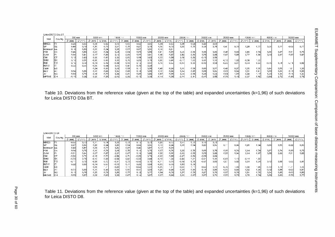
EU
RA
ME
T S
upplementary C
omparison C
omparison of laser distance m
easuring instruments
P
age 30 of 60
Table 10 Deviations from the reference value (given at the top of the table) and expanded uncertainties (k=196) of such deviations for Leica DISTO D3a BT
Table 11 Deviations from the reference value (given at the top of the table) and expanded uncertainties (k=196) of such deviations for Leica DISTO D8
EURAMET Supplementary Comparison Comparison of laser distance measuring instruments
Page 31 of 60
11 En Tables Results with En gt 1 are marked with red color in Tables below En values are calculated by Di U(Di) with Di and U(Di) as given on page 19
Table 12 BOSCH DLE50
Lab Distance (mm) 300 5000 10000 15000 20000 25000 30000 35000 40000 45000 50000
MIKES -058 017 -019 -023 035 -002 -096 SP 020 019 006 005 009 059 064 037 028 097 001
Metrosert -030 -031 -003 018 032 PTB 001 029 022 -006 011 -036 001 -023 -075 -083 001 GUM -033 -005 -018 -009 000 006 017 005 -026 -028 019 CMI -003 020 -009 004 005 -022 028 SMU 006 -049 -034 -023 -017 -057 051 039 021 INM 032 031 037 006 020 005 -079 -119 -272 -260 -269
INRIM 025 -013 000 096 CEM -032 -022 -041 -039 -004 -038 080 001 -094 -047 BEV -010 007 000 -001 008 -011 037 013 -001 008 -001 JV -019 -016 025 -055 055 060 068 163 122 060 089
METAS 038 012 -005 007 -107 004 -024 002 -070 037 -052
Table 13 BOSCH GLM150
Lab Distance (mm) 300 5000 10000 15000 20000 25000 30000 35000 40000 45000 50000
MIKES 005 -002 019 018 027 019 062 SP 003 068 029 023 051 008 015 016 -005 -001 038
Metrosert -061 -011 -022 -021 -003 PTB 066 074 062 062 034 053 047 048 047 091 064 GUM -007 -014 007 -018 000 023 020 033 014 032 038 CMI -057 -032 -030 -064 -050 -047 000 SMU 023 -024 -060 012 062 001 -003 050 047 INM -022 017 -003 002 -003 054 005 -006 016 -022 -055
INRIM 079 -052 -050 -026 -034 -042 CEM 002 002 -034 -020 -029 -077 -077 -077 -074 -104 BEV -004 -002 -007 010 -042 -042 -029 -011 -028 -022 -030 JV 003 015 040 011 -020 021 -029 -005 028 036 058
METAS -047 -020 005 002 -012 -033 -054 -065 -053 -082 -040
Table 14 Leica DISTO D3a BT
Lab Distance (mm) 300 5000 10000 15000 20000 25000 30000 35000 40000 45000 50000
MIKES 008 094 050 -011 028 051 045 SP 033 038 056 017 053 065 076 051 017 071 011
Metrosert -060 -004 -037 -014 -002 PTB 067 000 070 030 089 062 061 081 124 050 072 GUM 023 019 035 008 038 053 029 058 070 064 063 CMI -001 -004 027 -011 011 034 -033 SMU 002 -013 -019 007 -013 -055 045 -013 -042 INM 002 -039 -058 001 002 -045 -080 -051 -102 -101 -378
INRIM 070 -020 063 101 CEM -028 -004 -004 -064 003 -002 -050 -022 -093 -160 BEV -032 -019 -019 004 -011 -037 -017 -002 -025 005 012 JV 027 019 027 042 046 039 043 048 072 115 024
METAS -091 -008 -102 -098 -111 -103 -092 -080 -073 -108 -043
EURAMET Supplementary Comparison Comparison of laser distance measuring instruments
Page 32 of 60
Table 15 Leica DISTO D8
Lab Distance (mm) 300 5000 10000 15000 20000 25000 30000 35000 40000 45000 50000
MIKES 025 013 058 036 038 061 022 SP 057 026 040 016 013 016 025 017 -007 -019 007
Metrosert -021 006 -016 -043 -019 PTB 040 011 035 -005 -011 -002 -004 035 047 022 069 GUM -028 005 -025 031 039 -015 029 048 041 052 072 CMI -104 -026 -072 -057 -006 -017 -015 SMU -067 -017 -051 -026 -016 -054 -004 -001 -016 INM 021 -014 009 003 -017 -031 -010 007 029 036 041
INRIM 076 -024 -004 047 -007 083 CEM 004 -009 002 -033 -051 -059 -097 -077 -116 -134 BEV -057 -014 -051 -093 -024 -027 -021 -036 -038 -028 -041 JV 014 031 047 030 044 043 035 056 093 108 030
METAS 035 007 026 038 -013 -024 -011 -048 -089 -074 -066
12 Conclusions It was the first comparison of EDMs For most of the laboratories it was an important opportunity to validate their measurement instrumentation and procedure It allowed to become aware of potential problems and to take corrective actions in changing the procedure
For the evaluation of the reference value the weighted mean approach has been chosen although the consistency check according to procedure A of Ref [1] failed in many cases A more complicated procedure for the evaluation of the reference value was proposed which slightly changes the uncertainty of the reference value
In total there were 23 En values larger than 1 This represents 47 of the full set of 482 results It is less than the 5 of possible values being out of the expanded uncertainty of the reference value for k=2
The uncertainty of the results mainly comes from the uncertainty of the reproducibility It is difficult to distinguish between Labrsquos calibration and measurement capability
The comparison shows a global compliance with declared CMCs independently of whether some participant can have a high percentage of values not compliant with its CMC due to the influence of the artifact and the estimation of its uncertainty
13 References [1] M G Cox The evaluation of key comparison data Metrologia 39 589 ndash 595 (2002)
[2] R Thalmann EUROMET 677 ndash Steel Tape Measures Final report (2004)
[3] F Pollinger personal communication
EURAMET Supplementary Comparison Comparison of laser distance measuring instruments
Page 33 of 60
Appendix 1 Description of the measurement equipmen t as reported by the laboratories
A11 MIKES Finland
Short description of measurement bench
MIKES interferometric bench is situated in an underground laboratory with air temperature and humidity control Typically air temperature is 20 plusmn 01 degC and humidity 45 plusmn 2 RH The linear guide on the top of the concrete beam comprises two parallel round shafts with adjustable fixtures every 1 m A carriage with ball bush bearings is moved along the rail and location of it is measured with reference interferometer HP-5529A Temperature of air is measured with 6 pt100 sensors and Keithley 2010 multimetre with 4-wire resistance mode Air pressure and humidity are measured with Vaisala PTU200 Updated Edleacuten equation by Boumlnsch amp Potulski is used for calculation of refractive index of air
For EDM calibration on the other end than laser interferometer is a fixed reference plate which is adjusted perpendicular to the laser beam Next to the reference plate is an adjustable base for EDM instrument with which it can be adjusted to point parallel and coincident with measurement arm of the interferometer A target plate adjusted perpendicular to laser beam is fixed to the carriage The calibration followed Abbe principle with some millimetre uncertainty in offset adjustment
First reference interferometer is set to zero when the target plate and reference plate are in contact then EDM is positioned and adjusted in its base The rear surface of the EDM is also slightly pressed against reference surface behind it Then the readings from both instruments are collected at selected locations For this calibration there is no fine adjustment of the target position so there are typically deviations of up to few millimetres from nominal locations Results are averages of 3-4 measurements
Additional remarks
The CMC entry MIKES has for EDM calibrations is based on calibration of length scales of high quality total stations and laser trackers This type of EDMs used in this comparison are not accurate enough for truly testing of MIKES calibration measurement capability
EURAMET Supplementary Comparison Comparison of laser distance measuring instruments
Page 34 of 60
A12 SP Sweden
Short description of measurement bench
The bench consists of a simple aluminium Uminusshaped profile with polished steel pins acting as supports for the tape The bench is a little over 50 m long and works as support for the reference tape and the calibrated EDMs simultaneously
Length measurement instrument
Comparison with reference steel tape
Temperature measurement system number and location of sensors
The tape temperature is continuously registered in 6 points equally distributed along the bench The air temperature is monitored during the measurements but not used for corrections
Additional remarks
The EDM support is placed approximately 2 cm vertically above the tape No visual aid is used
EURAMET Supplementary Comparison Comparison of laser distance measuring instruments
Page 35 of 60
A13 AS Metrosert Estonia
Short description of measurement bench
The 21-m bench is located in the designated corridor-like laboratory room The lab is air-conditioned and the stability of temperature is typically plusmn05 ordmC There are three humidity and temperature sensors in room for stability and gradient monitoring
Two stainless steel rails running in parallel are made of 3-m long rods The rails lay without fixed attachment on metal supports which are mounted on concrete base The base rests on pillars made of bricks
Length measurement instrument
Laser-interferometer system Renishaw ML10 was used as length measurement instrument
Laser interferometer gets temperature humidity and pressure data from itrsquos own measurement system EC10
Additional remarks
Due to the length of the bench only measurements up to 20 m could be made Five measurement series were made with each EDM
EURAMET Supplementary Comparison Comparison of laser distance measuring instruments
Page 36 of 60
A14 PTB Germany
Short description of measurement bench
The measurements were performed on the 50 m geodetic base of the PTB The comparator consists of a 50 m rail The laboratory is equipped with a network of 21 temperature sensors spaced by 25 m along the bench As depicted in fig 1 the EDM is mounted at one end of the comparator the reflector is fixed vertically on the carriage A large retroreflector is mounted approximately 150 mm below the EDM reflector on the carriage reflecting the beam of the reference interferometer The deviation of the length due to tilting carriage (Abbe error) has been investigated along the bench by comparison of two interferometers It remains smaller than 100 microm The distance of the first position of 300 mm with respect to the back side of the EDM is determined by a gauge block of 300 mm length and a thickness of 10 mm This procedure is depicted for one of the comparison standards in figure 2
For the calibration the desired positions are programmed After the carriage reaches a measurement position the operator waits for another 30 s for the carriage to settle In control experiments the remaining movement between positioning and measurement remained smaller than 2 microm The operator then activates the measurement of the EDM reads the indicated position and writes it down The procedure is repeated for twelve times at every position the mean of the 12 measurements represents the ldquoindicated distance by the EDMrdquo All measurements of a single run at one position are performed within approximately one minute The complete measurement was repeated for four times
Length measurement instrument
The reference length is determined by a frequency-calibrated laser interferometer (Agilent 5519A) The reference interferometer is set up in Michelson geometry the signals being digitalised by a Heidenhain IK 121 card The index of refraction is determined by the external weather station of the geodetic base consisting of 21 Pt-100 temperature sensors spaced 25 m along the bench two humidity sensors (Testo 650) and two pressure sensors (Setra 370 and DPI 141) The environmental parameters are used to determine the index of refraction for the reference measurement deploying the modification of the Edleacuten equation by Boumlnsch and Potulski
EURAMET Supplementary Comparison Comparison of laser distance measuring instruments
Page 37 of 60
A15 CMI Czech Republic
Description of measurement bench
The EDMs were measured on 30 m long measuring bench equipped by laser interferometer (LI) Renishaw ML10 (pic 1 and 2) calibrated traceable to national standard of length and quantities of environmental sensors The target plate and retroreflector of the LI were fixed on a moving part of the bench and each EDM was fixed in horizontal position by clamps (pic 3) LI and EDM are placed on opposite ends of bench the Abbe offset was lt10 mm for some of them and lt50mm for all The value of LI was reset (to zero) at position corresponding to the rear of the EDM (using 3D measuring arm FARO Quantum with uncertainty about 27microm) The perpendicularities of the EDM stop as well as target plate to the beam were also checked by FARO) Each EDM was 3x replaced and aligned the measurement (reading) was repeated 6 times for each alignment and position the mean value of these 3x6 measurements is stated in tables with results The uncertainty claimed covers the statistical uncertainty of single readings Only in case of Leica D8 (the best performing EDM in this comparison) we state also the uncertainty corresponding to the mean of 6 readings in last column (this uncertainty is smaller and better illustrates our CMC)
Length measurement instrument
- Laser interferometer Renishaw - Laser 633 nm Type ML10 - Compensator EC10 - 3D measuring arm FARO Quantum - 3D measuring arm FARO Quantum
EURAMET Supplementary Comparison Comparison of laser distance measuring instruments
Page 38 of 60
A16 SMU Slovakia
Short description of measurement bench
No bench is available at the SMU the measurements are being carried out in the underground corridor of the laboratory building with length of 428 m
The 50 m steel measuring tape KINEX was used as the reference laid on the floor and pulled by the force 50 N (the same force as had been applied during its calibration at the SMU) The calibration of reference tape was done at the SMU using ULM3m Zeiss with laser interferometer Agilent 5529 B (ie per 3 m parts)
Three mercury thermometers with the resolution of 01 degC were used along the measurement path each of them laid onto the tape and located at 667 m 1990 m (instead of 20 m because of this was one of measuring points) and 333 m respectively Each of them thus corresponded approximately to one third of the measured steel tape section
Regarding the 03 m measuring point the ULM3m Zeiss length measuring machine was used with the 300 mm gauge block as the reference
Length measurement instrument
We used our own target plate being fixed perpendicularly (within uncertainty stated) to the construction equipped with nonius and the camera holder transported manually along the steel tape The second construction was fixed to the tape by such a way that zero line of the tape corresponded to the rear of EDM (within uncertainty stated)
The position of the target is read on the monitor and 20 repeated readings of the EDM data took place in each measuring point (multiples of 5 m up to 40 m)
Concerning 03 m the 300 mm gauge block was fit between the target plate and the construction with EDM The distance of the EDM rear from the target plate corresponded to the length of gauge block (within uncertainty stated)
Additional remarks
The identical measurement method was used as we use to do within our calibration service although the results reporting is different ndash we provide the regression line calculated from the measurement of irregularly distributed points and corresponding uncertainty (k = 2) in the form of [a bL] mm (ie the same coefficients for each length in the range (0 ndash 42) m)
SMU hasnrsquot got this category in CMC tables
EURAMET Supplementary Comparison Comparison of laser distance measuring instruments
Page 39 of 60
A17 INM Romania
Short description of measurement bench
Geodesic base located in the basement of the laboratory with nominal length equal to 50 m having a mobile carriage thet support both laser He-Ne retroreflector and the target of the laser distance measuring instrument in the front of geodesic base exists a support where are aligned both laser interferometer and the laser distance measuring instruments
Length measurement instrument
Laser interferometer type Hewlett Packard model 5526 A with nominal length equal to 50 m resolution 0001 mm
U = 02 microm +0510-6L
Additional remarks
During the measurements the maximum gradient of temperature was equal to 05 degC
EURAMET Supplementary Comparison Comparison of laser distance measuring instruments
Page 40 of 60
A18 INRIM Italy
Short description of measurement bench
The facility for long distance measurements is located in a corridor of the gallery devoted to dimensional metrology The structure consists in a 28 m long rail fixed to a series of pillars which rest directly on the ground released from the vibrations of floor and wall The measuring system is based on a heterodyne interferometer whose mobile arm consists of a hollow retro-reflector mounted on a structure that can run along the rail so-called carriage A photograph of the facility is presented in Fig1
The carriage is moved by a micro-step motor the motor driver receives a digital pulse and converts it into an electrical pulse to run the motor Each pulse causes a rotation of the motor shaft of one step which amounts to 11000 of a complete revolution of the shaft If the pulse frequency increases the rotation becomes continuous with a speed that is directly proportional to the pulse frequency The speed ranges between few microms up to 27 ms with a resolution of 03 microms
Since the carriage must move back and forth automatically for a distance of almost 30 m a remote control to send pulses to the motor driver was implemented It consists of two parts a radio command which allows to set some general parameters of the carriage movement such as the movement direction and mode of travel (slow or fast) and a fast command which is performed by an amplitude modulated laser beam placed at the beginning of the track oriented towards the carriage A photo detector placed above the carriage receives the modulated laser beam which is transformed into pulses to be sent to the driver of the motor The modulation of the laser beam is implemented by a LabView program that controls a digital output of the data acquisition device
Length measurement instrument
The length measurement instrument is based on a heterodyne incremental interferometer The main beam of the interferometer with frequency f1 is generated by a frequency stabilized
EURAMET Supplementary Comparison Comparison of laser distance measuring instruments
Page 41 of 60
He-Ne laser calibrated with respect to the INRIM length standard and sent to the measurement arm the second beam is a portion of the first one diffracted by an acousto-optic modulator (AOM) with frequency f2 = f1 + 80 MHz The reference detector acquires the beat note signal at 80 MHz while the measurement detector acquires a signal at 80 MHz whose phase is varied due to the displacement of the retro-reflector moving on the rail In figure 2 the optical design of the interferometer is presented
Two different measuring techniques have been implemented
1 the ldquophase measuringrdquo technique based on fringes counting with a relative uncertainty of 5middot10-7 but limited at the maximum carriage speed of 3 cms
2 the ldquoDoppler frequency measurementrdquo technique for higher carriage speed based on the measurement of the Doppler frequency shift while the carriage runs
The second technique was validated by means of the comparison with the first technique at low speed with an agreement of the order of 3middot10-6 hence the Doppler frequency method could be considered validated within 01 mm over the whole rail path with the advantage of reducing the time needed to cover long distances so it was used for the EDM comparison
In order to obtain the distance covered by the carriage according to technique 2 the Doppler frequency is measured by a commercial high-performance counter (a Pendulum CNT-90) without dead time based on time stamping then it is converted in speed and integrated over time according to the following formula
( ) ( )int minus=minus= tffn
dtn
ffdairair
λλ
2
1
2
1
where d is the distance covered by the carriage f is the frequency of the measuring signal with the carriage at rest frsquo the frequency of the measuring signal with the carriage moving λi
is the wavelength of the laser in vacuum n - air is the air refractive index and ti is the integration time The difference frsquo-f is just the Doppler frequency due to the moving carriage
The time interval measurement resolution of the instrument is 100 ps and the time base is
EURAMET Supplementary Comparison Comparison of laser distance measuring instruments
Page 42 of 60
connected to the INRIM UTC so that the measurements of the Doppler frequency and the integration time are extremely accurate The environmental parameters such as air temperature atmospheric pressure partial pressure of water were monitored during the measurement process in order to calculate the value of air refractive index according to the Edlenrsquos formula
Comparison set-up
The different technical solutions adopted for the EDMs and for the target plate positioning are discussed in this paragraph and sketched in figure 3
Fig 3 picture of the EDM and target positioning area
Target plate positioning
In order to use the provided target plate an ad-hoc mounting was manufactured at INRIM it consists in a sort of picture frame made in aluminum which slightly clamps the target folded in half and gives it the necessary stiffness to be a reproducible target The upper part of the frame is L-shaped and allows it to be fixed to the carriage structure by means of two screws The rear part of the target mounting is depicted in figure 4 The target mounting was considered necessary because of the poor stiffness and planarity of the plastic target With the aluminium frame a planarity better than 01 mm was guaranteed The target plate is placed few centimetres next to the retro-reflector and normal to the interferometer beam axis since the EDM laser should be as close and parallel as possible to the reference beam
EURAMET Supplementary Comparison Comparison of laser distance measuring instruments
Page 43 of 60
Fig 4 picture of the rear part of the target plate mounting
EDMsrsquo positioning
The EDMs are placed on a cradle-like platform which is able to adjust the inclination of the EDM along the longitudinal axis (pitch angle) The platform height allows the EDMs to be at approx the same height as the interferometer beam A crucial role was played by the stop-wall placed behind the platform since it represents the ldquozero pointrdquo for all the length measurement Hence a particular effort was devoted to align the stop-wall so that it was normal to the interferometer beam axis and parallel to the target plate
Fig 5 detail of EDMsrsquo positioning the cradle-like platform and the stop-wall are well visible
EURAMET Supplementary Comparison Comparison of laser distance measuring instruments
Page 44 of 60
Target and stop-wall alignment
In order to have the stop-wall parallel to the target plate and normal to the interferometer beam axis the following procedure has been used
1) the stop-wall and the target plate were roughly placed trying to set them parallel and normal to the rail by eye (ie within few millimeters)
2) in order to check if the target was normal to the rail one EDM was positioned on the platform the pitch and yaw angles of the EDM were adjusted by observing the position of the EDM laser spot on the target plate when the target is moved along the rail fixed position means laser beam parallel to the carriage movement Then the target was moved until the end of the rail and a thin mirror was kept in contact with it hence observing the EDM laser reflected by the mirror it was possible to adjust the target tilt acting on the screws until the laser beam is reflected back to the source
3) finally in order to check the parallelism between the stop-wall and the target a tool made by a laser pointing orthogonally to its base was used the base was leant against the stop-wall and the laser was centered on the target when the target is near then the target was moved until the end of the rail hence observing the spot of the laser on the target it was possible to adjust the stop-wall orientation
The residual misalignment errors which we were not able to eliminate were kept into account in the uncertainty budget
Measurement of the first 30 cm
Due to the geometry of our set-up it was not possible to perform the first point of measurement by means of the interferometer indeed the carriage (hence the target) is not able to go in contact with the stop-wall
Fig 6 measurement of the first 30 cm the ruler touching the stop-wall and the target and the mechanical probe (in the back) touching the carriage are visible
EURAMET Supplementary Comparison Comparison of laser distance measuring instruments
Page 45 of 60
So a ruler made of aluminum with rounded ends and nominal length equal to 30 cm was adopted to set the distance between the target plate and the stop-wall for the first point of measurement as it is shown in figure 6 The ruler whose length was measured by a CMM machine was inserted between the target and the stop-wall leaning against the latter and the carriage was carefully moved towards the stop-wall until the target lightly touched the ruler A mechanical probe that touches the carriage structure when carriage is in the ldquo30 cmrdquo position was used as a reference measurement to check the repeatability of this distance after each measurement set
Fig 7 detail of the mechanical probe touching the carriage
Environmental parameters
The environmental parameters such as air temperature atmospheric pressure and humidity were monitored during the whole measurement process in order to calculate the value of air refractive index according to the Edlenrsquos formula
Among these parameters the temperature distribution along the mobile arm of the interferometer was our main concern mainly for two reasons
1 the temperature control of the gallery was not perfectly working during the measurement period so temperature drifts had to be monitored
2 longitudinal temperature gradients due to non uniform heating and to the presence of electronic instruments were pretty high
To the purpose 14 thermometers were uniformly dislocated along the rail and automatically recorded for all the measurement period Both temporal drifts and gradients along the path have been taken in account in the uncertainty budget In any case maximum temperature differences along the rail are within 1 degC In fig 8 an extract from the acquisition file is shown
Unfortunately the air conditioning system did not work well during the measurement campaign hence the measurements were performed at a mean temperature of 209 degC
EURAMET Supplementary Comparison Comparison of laser distance measuring instruments
Page 46 of 60
Fig 8 each curve represents the temperature distribution along the rail during the measurements campaign
Carriage waving
Since the rail is not perfectly straight and the measurement laser is not coincident with the measurement beam the Abbegrave error due to waving of the target must be considered A quantitative measurement and a qualitative measurement were carried out With an electronic level placed on the carriage the straightness on the vertical plane has been mapped with a half meter resolution (the data are reported in fig 9) With a laser placed on the carriage the horizontal and vertical waving are qualitatively compared by looking at the movements of the light spot on a target fixed to the rail end As a conclusion the horizontal and vertical waving are comparable in magnitude and the peak to peak error is of the order of 300 arcseconds
Fig 9 vertical waving of the target measured by an electronic level placed on the carriage
EURAMET Supplementary Comparison Comparison of laser distance measuring instruments
Page 47 of 60
Measurement procedure
The measurements were carried out according to the following procedure
The target was set in the starting position with the procedure described above
In sequence the four EDMs are positioned on the base the horizontal and vertical tilt are adjusted and the distance measurement is recorded An additional fifth EDM (Bosh DLE 150 property of INRiM) was included in the measurement sequence Each EDM is placed on the base and gently pushed against the reference wall in such a way that the measurement laser beam starting point is the same for all EDMs Than the horizontal and vertical angles were adjusted in order to hit the central point of the target indicated with two black marks (see pictures 3 and 6) with ldquovisualrdquo alignment The measurement button is then pressed several times (typically 5) and the average reading is recorded Typical dispersion between readings is within few last digit units In case the dispersion between readings is too large the anomaly is recorded
The carriage was then moved in the next position (about 5 m) and the measurement sequence was repeated for the 5 EDMs The operation is repeated up to 25 m The 25 m measurement is than repeated again as well as all the points till the first one so that each point is measured twice each set Since the carriage movement is ldquoopen looprdquo the positioning of the carriage was not exactly in the nominal 5 m intervals For each positioning the incremental displacement is measured by the interferometer in the Doppler mode Finally the measured values were averaged in order to give a single value for each nominal position
At the end of the measurement set when the carriage is at the 30 cm position again the sum of the interferometric measurements should be very close to zero The residual value is compared with the difference between the first and the final measurements of the mechanical probe The difference must be within the uncertainty of the Doppler technique otherwise some error occurred in the measurement set that must be repeated
At the end of the session 10 complete sets of measurements recorded from the 20th to the 30th of January 2012 have been considered for this report
Additional remarks
Effect of laser pointing
During a preliminary set of measurements we noticed a strong and unexpected dependence of the measurement result on the position of the laser spot on the target Indeed since no particular instructions were given about the relative position of the laser spot on target position (except to exclude the central joint between the two halves) we decided to work relatively close to the right side of the target -closer to the interferometer beam- in order to reduce the Abbegrave error We noticed very large errors at large distances in particular of the Leica DISTO D3a (see figure 10)
EURAMET Supplementary Comparison Comparison of laser distance measuring instruments
Page 48 of 60
Fig 10 errors of each EDM In a preliminary set of measurements
We also noticed that this error was strongly dependent on the position of the spot on the target For this reason we carried out a set of measurements at the maximum length in different positions of the target from one edge to the other according to figure 11 The results are reported in table V
EDM A B C D E
Leica D3a -4 +1 0 +24 +43
+2 0 +42 +40
-1 0 +38
Leica D8 0 0 0 2 +7
0 +12 +23
table V deviations (in mm) from the length measured at point C aiming the laser spot at different positions of the target (notations as in figure 11)
We tried to find an explanation to this effect in the shape of the laser spot if the spot was
EURAMET Supplementary Comparison Comparison of laser distance measuring instruments
Page 49 of 60
particularly defocused or had high diffraction some of the energy could fall out of the target and affect the measurement result In fact the images of the spots (shown in fig 12) do not support this hypothesis Finally we decided to use the center of the (half) target for the comparison
Changing the target
In order to investigate the influence of the target on the measurements a cardboard foil (400 x 400) mm was fixed to the target mounting and a complete set of measurements was performed The results reported in figure 13 and 14 do not show any evidence of a possible dependency of the EDM measurement on the target kind
EURAMET Supplementary Comparison Comparison of laser distance measuring instruments
Page 50 of 60
Measurement at 50 m
Although we are not able to perform traceable length measurements beyond 28 m we wanted to get a sense of EDMs behaviour at longer distances So a target (represented by a rack side wall) was placed at approximately 50 m one after the other the EDMrsquos were positioned on the base and pointed towards the target The measurements were repeated then the target was replaced by the target used for the comparison and a third set of measurements were performed To our great surprise all the EDMrsquos were in good agreement (within 2 or 3 mm for each set of measurement) even those which showed errors of the order of five to ten millimeters at 25 m namely BOSCH DLE 50 and LEICA DISTO D3a Therefore each set of measurements was averaged and the deviations from the mean value are reported in figure 15
EURAMET Supplementary Comparison Comparison of laser distance measuring instruments
Page 51 of 60
Fig 15 Deviations from average value of the measurements At 50 m
EURAMET Supplementary Comparison Comparison of laser distance measuring instruments
Page 52 of 60
A19 CEM Spain
Short description of the measurement bench
To make the measurements of EDMs we have used a reference line made of adjustable supports fixed on a wall of the laboratory Each support is nominally separated five metres from the previous one so we can generate reference lengths up to fifty metres with a pitch of five metres The supports are designed to accommodate both targets and handheld EDMs Distances between supports were measured by using a total station traced to national standards The relative angles of the bases have been measured and corrected
Fig 1 - View of three consecutive supports of the 50 m baseline (left) Lab technician situating an EDM on the first support of the baseline (right)
Length measurement instrument
The baseline was calibrated by using a total station Leica TDA5005 with spherical reflector the calibration uncertainty being 02 mm for k = 2
The target is provided by the comparison The quality of the target was judged as not good due to geometrical constructive errors and the lack of rigidity and stability We measured the flatness of the target surface the distance edge-surface and the angle between them by using a 3D coordinate measuring machine The results of flatness and angle were included in the uncertainty budget and the distance EDM-target was corrected for each EDM due to each beam impinged on a different point of the target
We were not able to measure the distance 0 to 03 m because the baseline pitch is 5 meters and although we are able to measure shorter values in a different facility the target was not appropriate for our bench
EURAMET Supplementary Comparison Comparison of laser distance measuring instruments
Page 53 of 60
Fig 2 - View of an EDM on the first support of the baseline (left) A closer look showing the support adjustments and the origin plate (right)
Fig 3 - View of the comparison target on one of the supports of the baseline (left) A closer look showing the target edge against the support rigid reference (right)
Measurement method
The measurements were carried out by comparison against the known values of the calibrated baseline (metallic references on supports)
Environmental conditions were maintained within the following limits
- Temperature 20 ordmC plusmn 05 ordmC
- Humidity 45 plusmn 10
Each laser distance measuring instrument was placed at the first support of the base and aligned so that the laser beam was perpendicular to the target as indicated by the comparison protocol
For each measurement we took the average of thirty measurements It permitted us to evaluate the repeatability of the instrument
EURAMET Supplementary Comparison Comparison of laser distance measuring instruments
Page 54 of 60
A110 BEV Austria
Short description of the measurement bench
Fig 1 Carriage of tape bench View from the laser interferometer side Retroreflector mounted on the vertical plate the EDM target is mounted on the backside
Fig 2 Support for the DUT Adjustable with 2 translational and 2 rotational degrees of freedom respectively
Fig 3 Setting of the 300 mm starting position Note the rough-and-ready mounted target plate
Fig 4 Laser interferometer side of the bench The DUT is 50 m away on the other side
EURAMET Supplementary Comparison Comparison of laser distance measuring instruments
Page 55 of 60
Measurement procedure 1 The EDM is positioned with the help of a 4-axis positioning stage so that its laser beam is
coaxial with the measurement direction of the laser interferometer (in head on configuration)
2 The EDM is removed from its support The bench carriage is positioned so that the distance of the target plate from the EDM back support is 300 mm A length bar with spherical faces is used for this adjustment The laser interferometer is preset to 300 mm and the EDM is put back on its support
3 At each position 10 consecutive measurements are taken (repeatability) and the carriage is moved to the next position The carriage is manually moved under control of the laser interferometer until it is within plusmn30 microm at the correct position (Exception for the DLE 150 the target is not positioned at 10 m but at 10 m ndash 1 mm to make use of the higher resolution) The indicated (not the nominal) distance of the laser interferometer is recorded for the determination of the deviation
4 After reaching the 50 m position all points are measured in reverse order (bidirectional) Immediately after the last measurement the EDM is removed and the indication using the 300 mm length bar is checked (thus noting a possible drift of the setup)
5 Each instrument was measured 4 times according to this procedure on different days (reproducibility of bench and instrument)
Length measurement instrument
Agilent laser interferometer with long range option The bench was completed short time before performing these measurement So the characterisation was not complete and the respective measurement uncertainty of the laser interferometer is estimated rather high But anyway its contribution to the overall uncertainty can nearly be neglected
Additional remarks
The uncertainty originating from the DUT is the dominating uncertainty contribution Specifically the resolution of the two Bosch instruments (1 mm) and the repeatability are the largest contributions For the DLA 50 the pooled standard deviation of a reading at 50 m is larger than 2 mm Moreover the length dependence is not a simple function
All of the instruments show a significant deviation of the laser beam from the normal of the back (reference) face of the instrument The measured angles reach from 04deg (D3a) to 11deg (DLE 50) This leads depending on the outer dimensions of the instruments to a constant uncertainty contribution of 02 mm in our setup It must be noted that the reference faces are not well defined in most of the instruments
The reproducibility is quite different for the four instruments so only part of it originates from the setup For CMC claims we will use the standard uncertainty value of the most reproducible instrument (D3a) which amounts to 013 mm For an ideal instrument with a resolution of 01 mm and perfect repeatability we would thus have a constant expanded uncertainty of 053 mm up to 50 m
EURAMET Supplementary Comparison Comparison of laser distance measuring instruments
Page 56 of 60
A111 JV Norway
Short description of measurement bench
EDM under calibration and the reference system are aligned along a 50 m measurement bench with rails to carry the linear movement of a target plate for the EDM and a corner cube reflector for the reference system The distance between parallel axis of EDM and axis of the reference system is 130 mm Abbe error due to angle errors for the movement is smaller than 01 mm and is corrected for at each measurement point At long lengths an aperture is used approximately midway between the target plate and the EDM to avoid interfering stray light to the EDM
Alignment procedure
1) Alignment of reference system to the movement of the carriage (rails)
2) Alignment of the EDM to the movement of the carriage (rails)
3) Alignment of a plane mirror at the position of the target plate using back-reflection to the EDM output (normal incident of light on the mirror)
4) Take out the EDM and align the zero reference plate at the back of the EDM to the plane mirror
5) The mirror is replaced by the target plate and the target plate is aligned to the zero reference plate
6) Zero setting of the reference measurement system when target plate is at zero distance to the reference plate at the back of the EDM
7) Put the EDM back in position and realign it to the movement of the carriage (rails)
8) Zero setting of the EDM to the reference plate
Image 1) Image 2) Image 3) Image 4)
Image 1) Items 5) ndash 6) in alignment procedure
Fixture for HP linear interferometer is seen bottom right Part of Wyler instrument is seen to the left blue colour
Image 2) Items 7) and 8) in alignment procedure
Micrometer screws for angle alignment in two directions and linear translation for zero setting of the EDM Push button on the EDM is positioned at the tilting point of the angle adjustment table to maximize stability during measurement HP 5519 A laser head is seen to the right
Image 3) Ready to measure at selected distances from zero point the reference plate
Image 4) EDM spot size at 50 m
Length measurement instrument
- Hewlett Packard Dynamic Calibrator 5519 A (max range 80 m)
- Pressure air temperature humidity Vaisala
EURAMET Supplementary Comparison Comparison of laser distance measuring instruments
Page 57 of 60
- Digital high resolution angle measurement Wyler
I used our own target plate which is of the same type as enclosed in the artefact suitcase article number 766560 from Leica but with reduced size width x hight = 90 x 137 mm
The zero reference plate is of similar type and size
Before measurements batteries of EDMs were switched to new batteries Old batteries are switched back after calibration
For L gt 5 m an aperture of similar size as the target plate is used approximately midway between the EDM and the target plate
Additional remarks
Reports on EDM indicated values at each measurement point is the average value of n = 5 repetitions A linear model of the standard deviation for the repeatability of the EDM readings at different lengths is estimated using m = 20 repetitions at least 5 positions along the scale An estimate of the length dependent repeatability is made for each instrument
The expanded uncertainty U(95) is rounded up to the limiting resolution of 1 mm in the interval 10 m to 40 m for Bosch GLM 150
After the calibration we also estimated the angle error of the optical axis of the EDM to its back plane (back reference of EDM) Bosch DLE 50 26 mrad up measured at 50 m Bosch GLM 150 8 mrad to the left measured at 50 m Leica DISTO D3a 37 mrad down measured at 20 m Leica DISTO D8 2 mrad to the left and 4 mrad down (45 mrad total) measured at 20 m
The distance between parallel walls will be measured too large if the back plane is assumed to be normal to the optical axis of the EDM by ∆LL = (1cosα ndash 1) Bosch DLE 50 ∆LL = 340 ppm (∆L = 17 mm at L = 50 m) Bosch GLM 150 ∆LL = 32 ppm (∆L = 16 mm at L = 50 m) Leica DISTO D3a ∆LL = 7 ppm (∆L = 034 mm at L = 50 m) Leica DISTO D8 ∆LL = 10 ppm (∆L = 05 mm at L = 50 m)
EURAMET Supplementary Comparison Comparison of laser distance measuring instruments
Page 58 of 60
A112 METAS Switzerland
Short description of measurement bench (photo recom mended)
50 m bench with laser interferometer (see photo detailed description in Michel Degoumois Un Long laboratoire de mesure OFMETinfo Vol5 No 2 1998)
Length measurement instrument
HP 5529 B laser interferometer range 80 m
EURAMET Supplementary Comparison Comparison of laser distance measuring instruments
Page 59 of 60
A113 GUM Poland
Short description of measurement bench
The 50 m bench is situated in the corridor laboratory located in the basement and has its own air conditioning system with air temperature 20 plusmn 1 degC and humidity 50 plusmn 10 RH The measuring carriage is carried microscope with CCD camera and the optics associated with the interferometer The carriage is driven using belt-transmission and electrical engine with remote ndash controlled variable speed drive
The EDM was placed on the fixed adjustable plate on the other end than laser interferometer The target plate of the EDM was placed on the measuring carriage For each EDM 3 series of measurement were done Before the each measurement EDM was repositioned and aligned again
Length measurement instrument
1 Laser interferometer HP 5529A with long-range option laser head HP 5519A
2 Ambient measurement system number and location of sensors - 20 air temperature sensors type YSI with KEITHLEY multimeter they are placed very
close to axis of the laser beam - air pressure and humidity are measured with Vaisala barometer and
thermohigrometer - CO2 content was measured with analyzer made by Intelli Charge type SPN 4462
EURAMET Supplementary Comparison Comparison of laser distance measuring instruments
Page 60 of 60
Appendix 2 Corrections of reports
131 CEM Spain
CEM reported two errors in their report
1) Bosch GLM 150 EDM error for 35 m should be -08 mm instead of the indicated 08 mm
2) Leica DISTO D8 EDM error for 35 m should be -019 mm instead of the indicated 019 mm
Proposed corrections have been included in Tables 2 and 4 of the Final Report
132 AS Metrosert Estonia
AS Metrosert reported mixed up of all results for Bosch DLE 50 and Bosch GLM 150 The results and uncertainties sent for DLE 50 was results for GLM 150 and vice versa
Proposed corrections have been included in Tables 1 and 2 of the Final Report
133 INRIM Italy
Among the data reported from INRIM some anomalies were found in the measurements of BOSCH DLE 50 and LEICA DISTO D3a at distances of 20 and 25 m
After preliminary discussion on Draft A it was understood that those anomalies could be explained as a sensitivity of said instruments to the laser light that once diffused by the target is reflected by surfaces parallel to the measurement axis and detected together with the wanted signal The superimposition of the two signals can cause a ldquopullingrdquo effect leading to an overestimation of the distance being the reflected path always longer than the direct one Indeed in the INRIMrsquos set-up the target was mounted pretty close to the flat rail used for the carriage movement being likely responsible for unwanted reflections that disturbed the measurements
Since the errors reported in INRIMrsquos measurements can be ascribed to a defect of BOSCH DLE 50 and LEICA DISTO D3a andor to a lack of description of the working conditions of said instruments INRIM asked to eliminate its measurement points at 20 and 25 m of said instruments from the comparison
Proposed corrections have been included in Tables 1 and 3 of the Final Report
134 JV Norway
Justervesenet has changed the procedure and introduced two apertures instead of only one aperture (iris) which was positioned at half distance between EDM and target The reason is that the reference beam also has an aperture and it is positioned right below the beam from the EDM (130 mm distance between axes) Some diffusively reflected stray light from the EDM target might enter the aperture for the reference beam reflect at the measurement table and reach the detector of the EDM In our calibration set-up we have only seen problems at L gt 30 m We will position the first aperture at ca 5 m from the EDM and then the second aperture at ca 25 m This combination of two apertures will effectively eliminate interference of stray light from the measurement table to the EDM detector for all lengths up to 50 m
Justervesenet also increases the uncertainty component regarding repeatability reproducibility so that the expanded uncertainty increases from 14 mm to 15 mm

EURAMET Supplementary Comparison Comparison of laser distance measuring instruments
Page 33 of 60
Appendix 1 Description of the measurement equipmen t as reported by the laboratories
A11 MIKES Finland
Short description of measurement bench
MIKES interferometric bench is situated in an underground laboratory with air temperature and humidity control Typically air temperature is 20 plusmn 01 degC and humidity 45 plusmn 2 RH The linear guide on the top of the concrete beam comprises two parallel round shafts with adjustable fixtures every 1 m A carriage with ball bush bearings is moved along the rail and location of it is measured with reference interferometer HP-5529A Temperature of air is measured with 6 pt100 sensors and Keithley 2010 multimetre with 4-wire resistance mode Air pressure and humidity are measured with Vaisala PTU200 Updated Edleacuten equation by Boumlnsch amp Potulski is used for calculation of refractive index of air
For EDM calibration on the other end than laser interferometer is a fixed reference plate which is adjusted perpendicular to the laser beam Next to the reference plate is an adjustable base for EDM instrument with which it can be adjusted to point parallel and coincident with measurement arm of the interferometer A target plate adjusted perpendicular to laser beam is fixed to the carriage The calibration followed Abbe principle with some millimetre uncertainty in offset adjustment
First reference interferometer is set to zero when the target plate and reference plate are in contact then EDM is positioned and adjusted in its base The rear surface of the EDM is also slightly pressed against reference surface behind it Then the readings from both instruments are collected at selected locations For this calibration there is no fine adjustment of the target position so there are typically deviations of up to few millimetres from nominal locations Results are averages of 3-4 measurements
Additional remarks
The CMC entry MIKES has for EDM calibrations is based on calibration of length scales of high quality total stations and laser trackers This type of EDMs used in this comparison are not accurate enough for truly testing of MIKES calibration measurement capability
EURAMET Supplementary Comparison Comparison of laser distance measuring instruments
Page 34 of 60
A12 SP Sweden
Short description of measurement bench
The bench consists of a simple aluminium Uminusshaped profile with polished steel pins acting as supports for the tape The bench is a little over 50 m long and works as support for the reference tape and the calibrated EDMs simultaneously
Length measurement instrument
Comparison with reference steel tape
Temperature measurement system number and location of sensors
The tape temperature is continuously registered in 6 points equally distributed along the bench The air temperature is monitored during the measurements but not used for corrections
Additional remarks
The EDM support is placed approximately 2 cm vertically above the tape No visual aid is used
EURAMET Supplementary Comparison Comparison of laser distance measuring instruments
Page 35 of 60
A13 AS Metrosert Estonia
Short description of measurement bench
The 21-m bench is located in the designated corridor-like laboratory room The lab is air-conditioned and the stability of temperature is typically plusmn05 ordmC There are three humidity and temperature sensors in room for stability and gradient monitoring
Two stainless steel rails running in parallel are made of 3-m long rods The rails lay without fixed attachment on metal supports which are mounted on concrete base The base rests on pillars made of bricks
Length measurement instrument
Laser-interferometer system Renishaw ML10 was used as length measurement instrument
Laser interferometer gets temperature humidity and pressure data from itrsquos own measurement system EC10
Additional remarks
Due to the length of the bench only measurements up to 20 m could be made Five measurement series were made with each EDM
EURAMET Supplementary Comparison Comparison of laser distance measuring instruments
Page 36 of 60
A14 PTB Germany
Short description of measurement bench
The measurements were performed on the 50 m geodetic base of the PTB The comparator consists of a 50 m rail The laboratory is equipped with a network of 21 temperature sensors spaced by 25 m along the bench As depicted in fig 1 the EDM is mounted at one end of the comparator the reflector is fixed vertically on the carriage A large retroreflector is mounted approximately 150 mm below the EDM reflector on the carriage reflecting the beam of the reference interferometer The deviation of the length due to tilting carriage (Abbe error) has been investigated along the bench by comparison of two interferometers It remains smaller than 100 microm The distance of the first position of 300 mm with respect to the back side of the EDM is determined by a gauge block of 300 mm length and a thickness of 10 mm This procedure is depicted for one of the comparison standards in figure 2
For the calibration the desired positions are programmed After the carriage reaches a measurement position the operator waits for another 30 s for the carriage to settle In control experiments the remaining movement between positioning and measurement remained smaller than 2 microm The operator then activates the measurement of the EDM reads the indicated position and writes it down The procedure is repeated for twelve times at every position the mean of the 12 measurements represents the ldquoindicated distance by the EDMrdquo All measurements of a single run at one position are performed within approximately one minute The complete measurement was repeated for four times
Length measurement instrument
The reference length is determined by a frequency-calibrated laser interferometer (Agilent 5519A) The reference interferometer is set up in Michelson geometry the signals being digitalised by a Heidenhain IK 121 card The index of refraction is determined by the external weather station of the geodetic base consisting of 21 Pt-100 temperature sensors spaced 25 m along the bench two humidity sensors (Testo 650) and two pressure sensors (Setra 370 and DPI 141) The environmental parameters are used to determine the index of refraction for the reference measurement deploying the modification of the Edleacuten equation by Boumlnsch and Potulski
EURAMET Supplementary Comparison Comparison of laser distance measuring instruments
Page 37 of 60
A15 CMI Czech Republic
Description of measurement bench
The EDMs were measured on 30 m long measuring bench equipped by laser interferometer (LI) Renishaw ML10 (pic 1 and 2) calibrated traceable to national standard of length and quantities of environmental sensors The target plate and retroreflector of the LI were fixed on a moving part of the bench and each EDM was fixed in horizontal position by clamps (pic 3) LI and EDM are placed on opposite ends of bench the Abbe offset was lt10 mm for some of them and lt50mm for all The value of LI was reset (to zero) at position corresponding to the rear of the EDM (using 3D measuring arm FARO Quantum with uncertainty about 27microm) The perpendicularities of the EDM stop as well as target plate to the beam were also checked by FARO) Each EDM was 3x replaced and aligned the measurement (reading) was repeated 6 times for each alignment and position the mean value of these 3x6 measurements is stated in tables with results The uncertainty claimed covers the statistical uncertainty of single readings Only in case of Leica D8 (the best performing EDM in this comparison) we state also the uncertainty corresponding to the mean of 6 readings in last column (this uncertainty is smaller and better illustrates our CMC)
Length measurement instrument
- Laser interferometer Renishaw - Laser 633 nm Type ML10 - Compensator EC10 - 3D measuring arm FARO Quantum - 3D measuring arm FARO Quantum
EURAMET Supplementary Comparison Comparison of laser distance measuring instruments
Page 38 of 60
A16 SMU Slovakia
Short description of measurement bench
No bench is available at the SMU the measurements are being carried out in the underground corridor of the laboratory building with length of 428 m
The 50 m steel measuring tape KINEX was used as the reference laid on the floor and pulled by the force 50 N (the same force as had been applied during its calibration at the SMU) The calibration of reference tape was done at the SMU using ULM3m Zeiss with laser interferometer Agilent 5529 B (ie per 3 m parts)
Three mercury thermometers with the resolution of 01 degC were used along the measurement path each of them laid onto the tape and located at 667 m 1990 m (instead of 20 m because of this was one of measuring points) and 333 m respectively Each of them thus corresponded approximately to one third of the measured steel tape section
Regarding the 03 m measuring point the ULM3m Zeiss length measuring machine was used with the 300 mm gauge block as the reference
Length measurement instrument
We used our own target plate being fixed perpendicularly (within uncertainty stated) to the construction equipped with nonius and the camera holder transported manually along the steel tape The second construction was fixed to the tape by such a way that zero line of the tape corresponded to the rear of EDM (within uncertainty stated)
The position of the target is read on the monitor and 20 repeated readings of the EDM data took place in each measuring point (multiples of 5 m up to 40 m)
Concerning 03 m the 300 mm gauge block was fit between the target plate and the construction with EDM The distance of the EDM rear from the target plate corresponded to the length of gauge block (within uncertainty stated)
Additional remarks
The identical measurement method was used as we use to do within our calibration service although the results reporting is different ndash we provide the regression line calculated from the measurement of irregularly distributed points and corresponding uncertainty (k = 2) in the form of [a bL] mm (ie the same coefficients for each length in the range (0 ndash 42) m)
SMU hasnrsquot got this category in CMC tables
EURAMET Supplementary Comparison Comparison of laser distance measuring instruments
Page 39 of 60
A17 INM Romania
Short description of measurement bench
Geodesic base located in the basement of the laboratory with nominal length equal to 50 m having a mobile carriage thet support both laser He-Ne retroreflector and the target of the laser distance measuring instrument in the front of geodesic base exists a support where are aligned both laser interferometer and the laser distance measuring instruments
Length measurement instrument
Laser interferometer type Hewlett Packard model 5526 A with nominal length equal to 50 m resolution 0001 mm
U = 02 microm +0510-6L
Additional remarks
During the measurements the maximum gradient of temperature was equal to 05 degC
EURAMET Supplementary Comparison Comparison of laser distance measuring instruments
Page 40 of 60
A18 INRIM Italy
Short description of measurement bench
The facility for long distance measurements is located in a corridor of the gallery devoted to dimensional metrology The structure consists in a 28 m long rail fixed to a series of pillars which rest directly on the ground released from the vibrations of floor and wall The measuring system is based on a heterodyne interferometer whose mobile arm consists of a hollow retro-reflector mounted on a structure that can run along the rail so-called carriage A photograph of the facility is presented in Fig1
The carriage is moved by a micro-step motor the motor driver receives a digital pulse and converts it into an electrical pulse to run the motor Each pulse causes a rotation of the motor shaft of one step which amounts to 11000 of a complete revolution of the shaft If the pulse frequency increases the rotation becomes continuous with a speed that is directly proportional to the pulse frequency The speed ranges between few microms up to 27 ms with a resolution of 03 microms
Since the carriage must move back and forth automatically for a distance of almost 30 m a remote control to send pulses to the motor driver was implemented It consists of two parts a radio command which allows to set some general parameters of the carriage movement such as the movement direction and mode of travel (slow or fast) and a fast command which is performed by an amplitude modulated laser beam placed at the beginning of the track oriented towards the carriage A photo detector placed above the carriage receives the modulated laser beam which is transformed into pulses to be sent to the driver of the motor The modulation of the laser beam is implemented by a LabView program that controls a digital output of the data acquisition device
Length measurement instrument
The length measurement instrument is based on a heterodyne incremental interferometer The main beam of the interferometer with frequency f1 is generated by a frequency stabilized
EURAMET Supplementary Comparison Comparison of laser distance measuring instruments
Page 41 of 60
He-Ne laser calibrated with respect to the INRIM length standard and sent to the measurement arm the second beam is a portion of the first one diffracted by an acousto-optic modulator (AOM) with frequency f2 = f1 + 80 MHz The reference detector acquires the beat note signal at 80 MHz while the measurement detector acquires a signal at 80 MHz whose phase is varied due to the displacement of the retro-reflector moving on the rail In figure 2 the optical design of the interferometer is presented
Two different measuring techniques have been implemented
1 the ldquophase measuringrdquo technique based on fringes counting with a relative uncertainty of 5middot10-7 but limited at the maximum carriage speed of 3 cms
2 the ldquoDoppler frequency measurementrdquo technique for higher carriage speed based on the measurement of the Doppler frequency shift while the carriage runs
The second technique was validated by means of the comparison with the first technique at low speed with an agreement of the order of 3middot10-6 hence the Doppler frequency method could be considered validated within 01 mm over the whole rail path with the advantage of reducing the time needed to cover long distances so it was used for the EDM comparison
In order to obtain the distance covered by the carriage according to technique 2 the Doppler frequency is measured by a commercial high-performance counter (a Pendulum CNT-90) without dead time based on time stamping then it is converted in speed and integrated over time according to the following formula
( ) ( )int minus=minus= tffn
dtn
ffdairair
λλ
2
1
2
1
where d is the distance covered by the carriage f is the frequency of the measuring signal with the carriage at rest frsquo the frequency of the measuring signal with the carriage moving λi
is the wavelength of the laser in vacuum n - air is the air refractive index and ti is the integration time The difference frsquo-f is just the Doppler frequency due to the moving carriage
The time interval measurement resolution of the instrument is 100 ps and the time base is
EURAMET Supplementary Comparison Comparison of laser distance measuring instruments
Page 42 of 60
connected to the INRIM UTC so that the measurements of the Doppler frequency and the integration time are extremely accurate The environmental parameters such as air temperature atmospheric pressure partial pressure of water were monitored during the measurement process in order to calculate the value of air refractive index according to the Edlenrsquos formula
Comparison set-up
The different technical solutions adopted for the EDMs and for the target plate positioning are discussed in this paragraph and sketched in figure 3
Fig 3 picture of the EDM and target positioning area
Target plate positioning
In order to use the provided target plate an ad-hoc mounting was manufactured at INRIM it consists in a sort of picture frame made in aluminum which slightly clamps the target folded in half and gives it the necessary stiffness to be a reproducible target The upper part of the frame is L-shaped and allows it to be fixed to the carriage structure by means of two screws The rear part of the target mounting is depicted in figure 4 The target mounting was considered necessary because of the poor stiffness and planarity of the plastic target With the aluminium frame a planarity better than 01 mm was guaranteed The target plate is placed few centimetres next to the retro-reflector and normal to the interferometer beam axis since the EDM laser should be as close and parallel as possible to the reference beam
EURAMET Supplementary Comparison Comparison of laser distance measuring instruments
Page 43 of 60
Fig 4 picture of the rear part of the target plate mounting
EDMsrsquo positioning
The EDMs are placed on a cradle-like platform which is able to adjust the inclination of the EDM along the longitudinal axis (pitch angle) The platform height allows the EDMs to be at approx the same height as the interferometer beam A crucial role was played by the stop-wall placed behind the platform since it represents the ldquozero pointrdquo for all the length measurement Hence a particular effort was devoted to align the stop-wall so that it was normal to the interferometer beam axis and parallel to the target plate
Fig 5 detail of EDMsrsquo positioning the cradle-like platform and the stop-wall are well visible
EURAMET Supplementary Comparison Comparison of laser distance measuring instruments
Page 44 of 60
Target and stop-wall alignment
In order to have the stop-wall parallel to the target plate and normal to the interferometer beam axis the following procedure has been used
1) the stop-wall and the target plate were roughly placed trying to set them parallel and normal to the rail by eye (ie within few millimeters)
2) in order to check if the target was normal to the rail one EDM was positioned on the platform the pitch and yaw angles of the EDM were adjusted by observing the position of the EDM laser spot on the target plate when the target is moved along the rail fixed position means laser beam parallel to the carriage movement Then the target was moved until the end of the rail and a thin mirror was kept in contact with it hence observing the EDM laser reflected by the mirror it was possible to adjust the target tilt acting on the screws until the laser beam is reflected back to the source
3) finally in order to check the parallelism between the stop-wall and the target a tool made by a laser pointing orthogonally to its base was used the base was leant against the stop-wall and the laser was centered on the target when the target is near then the target was moved until the end of the rail hence observing the spot of the laser on the target it was possible to adjust the stop-wall orientation
The residual misalignment errors which we were not able to eliminate were kept into account in the uncertainty budget
Measurement of the first 30 cm
Due to the geometry of our set-up it was not possible to perform the first point of measurement by means of the interferometer indeed the carriage (hence the target) is not able to go in contact with the stop-wall
Fig 6 measurement of the first 30 cm the ruler touching the stop-wall and the target and the mechanical probe (in the back) touching the carriage are visible
EURAMET Supplementary Comparison Comparison of laser distance measuring instruments
Page 45 of 60
So a ruler made of aluminum with rounded ends and nominal length equal to 30 cm was adopted to set the distance between the target plate and the stop-wall for the first point of measurement as it is shown in figure 6 The ruler whose length was measured by a CMM machine was inserted between the target and the stop-wall leaning against the latter and the carriage was carefully moved towards the stop-wall until the target lightly touched the ruler A mechanical probe that touches the carriage structure when carriage is in the ldquo30 cmrdquo position was used as a reference measurement to check the repeatability of this distance after each measurement set
Fig 7 detail of the mechanical probe touching the carriage
Environmental parameters
The environmental parameters such as air temperature atmospheric pressure and humidity were monitored during the whole measurement process in order to calculate the value of air refractive index according to the Edlenrsquos formula
Among these parameters the temperature distribution along the mobile arm of the interferometer was our main concern mainly for two reasons
1 the temperature control of the gallery was not perfectly working during the measurement period so temperature drifts had to be monitored
2 longitudinal temperature gradients due to non uniform heating and to the presence of electronic instruments were pretty high
To the purpose 14 thermometers were uniformly dislocated along the rail and automatically recorded for all the measurement period Both temporal drifts and gradients along the path have been taken in account in the uncertainty budget In any case maximum temperature differences along the rail are within 1 degC In fig 8 an extract from the acquisition file is shown
Unfortunately the air conditioning system did not work well during the measurement campaign hence the measurements were performed at a mean temperature of 209 degC
EURAMET Supplementary Comparison Comparison of laser distance measuring instruments
Page 46 of 60
Fig 8 each curve represents the temperature distribution along the rail during the measurements campaign
Carriage waving
Since the rail is not perfectly straight and the measurement laser is not coincident with the measurement beam the Abbegrave error due to waving of the target must be considered A quantitative measurement and a qualitative measurement were carried out With an electronic level placed on the carriage the straightness on the vertical plane has been mapped with a half meter resolution (the data are reported in fig 9) With a laser placed on the carriage the horizontal and vertical waving are qualitatively compared by looking at the movements of the light spot on a target fixed to the rail end As a conclusion the horizontal and vertical waving are comparable in magnitude and the peak to peak error is of the order of 300 arcseconds
Fig 9 vertical waving of the target measured by an electronic level placed on the carriage
EURAMET Supplementary Comparison Comparison of laser distance measuring instruments
Page 47 of 60
Measurement procedure
The measurements were carried out according to the following procedure
The target was set in the starting position with the procedure described above
In sequence the four EDMs are positioned on the base the horizontal and vertical tilt are adjusted and the distance measurement is recorded An additional fifth EDM (Bosh DLE 150 property of INRiM) was included in the measurement sequence Each EDM is placed on the base and gently pushed against the reference wall in such a way that the measurement laser beam starting point is the same for all EDMs Than the horizontal and vertical angles were adjusted in order to hit the central point of the target indicated with two black marks (see pictures 3 and 6) with ldquovisualrdquo alignment The measurement button is then pressed several times (typically 5) and the average reading is recorded Typical dispersion between readings is within few last digit units In case the dispersion between readings is too large the anomaly is recorded
The carriage was then moved in the next position (about 5 m) and the measurement sequence was repeated for the 5 EDMs The operation is repeated up to 25 m The 25 m measurement is than repeated again as well as all the points till the first one so that each point is measured twice each set Since the carriage movement is ldquoopen looprdquo the positioning of the carriage was not exactly in the nominal 5 m intervals For each positioning the incremental displacement is measured by the interferometer in the Doppler mode Finally the measured values were averaged in order to give a single value for each nominal position
At the end of the measurement set when the carriage is at the 30 cm position again the sum of the interferometric measurements should be very close to zero The residual value is compared with the difference between the first and the final measurements of the mechanical probe The difference must be within the uncertainty of the Doppler technique otherwise some error occurred in the measurement set that must be repeated
At the end of the session 10 complete sets of measurements recorded from the 20th to the 30th of January 2012 have been considered for this report
Additional remarks
Effect of laser pointing
During a preliminary set of measurements we noticed a strong and unexpected dependence of the measurement result on the position of the laser spot on the target Indeed since no particular instructions were given about the relative position of the laser spot on target position (except to exclude the central joint between the two halves) we decided to work relatively close to the right side of the target -closer to the interferometer beam- in order to reduce the Abbegrave error We noticed very large errors at large distances in particular of the Leica DISTO D3a (see figure 10)
EURAMET Supplementary Comparison Comparison of laser distance measuring instruments
Page 48 of 60
Fig 10 errors of each EDM In a preliminary set of measurements
We also noticed that this error was strongly dependent on the position of the spot on the target For this reason we carried out a set of measurements at the maximum length in different positions of the target from one edge to the other according to figure 11 The results are reported in table V
EDM A B C D E
Leica D3a -4 +1 0 +24 +43
+2 0 +42 +40
-1 0 +38
Leica D8 0 0 0 2 +7
0 +12 +23
table V deviations (in mm) from the length measured at point C aiming the laser spot at different positions of the target (notations as in figure 11)
We tried to find an explanation to this effect in the shape of the laser spot if the spot was
EURAMET Supplementary Comparison Comparison of laser distance measuring instruments
Page 49 of 60
particularly defocused or had high diffraction some of the energy could fall out of the target and affect the measurement result In fact the images of the spots (shown in fig 12) do not support this hypothesis Finally we decided to use the center of the (half) target for the comparison
Changing the target
In order to investigate the influence of the target on the measurements a cardboard foil (400 x 400) mm was fixed to the target mounting and a complete set of measurements was performed The results reported in figure 13 and 14 do not show any evidence of a possible dependency of the EDM measurement on the target kind
EURAMET Supplementary Comparison Comparison of laser distance measuring instruments
Page 50 of 60
Measurement at 50 m
Although we are not able to perform traceable length measurements beyond 28 m we wanted to get a sense of EDMs behaviour at longer distances So a target (represented by a rack side wall) was placed at approximately 50 m one after the other the EDMrsquos were positioned on the base and pointed towards the target The measurements were repeated then the target was replaced by the target used for the comparison and a third set of measurements were performed To our great surprise all the EDMrsquos were in good agreement (within 2 or 3 mm for each set of measurement) even those which showed errors of the order of five to ten millimeters at 25 m namely BOSCH DLE 50 and LEICA DISTO D3a Therefore each set of measurements was averaged and the deviations from the mean value are reported in figure 15
EURAMET Supplementary Comparison Comparison of laser distance measuring instruments
Page 51 of 60
Fig 15 Deviations from average value of the measurements At 50 m
EURAMET Supplementary Comparison Comparison of laser distance measuring instruments
Page 52 of 60
A19 CEM Spain
Short description of the measurement bench
To make the measurements of EDMs we have used a reference line made of adjustable supports fixed on a wall of the laboratory Each support is nominally separated five metres from the previous one so we can generate reference lengths up to fifty metres with a pitch of five metres The supports are designed to accommodate both targets and handheld EDMs Distances between supports were measured by using a total station traced to national standards The relative angles of the bases have been measured and corrected
Fig 1 - View of three consecutive supports of the 50 m baseline (left) Lab technician situating an EDM on the first support of the baseline (right)
Length measurement instrument
The baseline was calibrated by using a total station Leica TDA5005 with spherical reflector the calibration uncertainty being 02 mm for k = 2
The target is provided by the comparison The quality of the target was judged as not good due to geometrical constructive errors and the lack of rigidity and stability We measured the flatness of the target surface the distance edge-surface and the angle between them by using a 3D coordinate measuring machine The results of flatness and angle were included in the uncertainty budget and the distance EDM-target was corrected for each EDM due to each beam impinged on a different point of the target
We were not able to measure the distance 0 to 03 m because the baseline pitch is 5 meters and although we are able to measure shorter values in a different facility the target was not appropriate for our bench
EURAMET Supplementary Comparison Comparison of laser distance measuring instruments
Page 53 of 60
Fig 2 - View of an EDM on the first support of the baseline (left) A closer look showing the support adjustments and the origin plate (right)
Fig 3 - View of the comparison target on one of the supports of the baseline (left) A closer look showing the target edge against the support rigid reference (right)
Measurement method
The measurements were carried out by comparison against the known values of the calibrated baseline (metallic references on supports)
Environmental conditions were maintained within the following limits
- Temperature 20 ordmC plusmn 05 ordmC
- Humidity 45 plusmn 10
Each laser distance measuring instrument was placed at the first support of the base and aligned so that the laser beam was perpendicular to the target as indicated by the comparison protocol
For each measurement we took the average of thirty measurements It permitted us to evaluate the repeatability of the instrument
EURAMET Supplementary Comparison Comparison of laser distance measuring instruments
Page 54 of 60
A110 BEV Austria
Short description of the measurement bench
Fig 1 Carriage of tape bench View from the laser interferometer side Retroreflector mounted on the vertical plate the EDM target is mounted on the backside
Fig 2 Support for the DUT Adjustable with 2 translational and 2 rotational degrees of freedom respectively
Fig 3 Setting of the 300 mm starting position Note the rough-and-ready mounted target plate
Fig 4 Laser interferometer side of the bench The DUT is 50 m away on the other side
EURAMET Supplementary Comparison Comparison of laser distance measuring instruments
Page 55 of 60
Measurement procedure 1 The EDM is positioned with the help of a 4-axis positioning stage so that its laser beam is
coaxial with the measurement direction of the laser interferometer (in head on configuration)
2 The EDM is removed from its support The bench carriage is positioned so that the distance of the target plate from the EDM back support is 300 mm A length bar with spherical faces is used for this adjustment The laser interferometer is preset to 300 mm and the EDM is put back on its support
3 At each position 10 consecutive measurements are taken (repeatability) and the carriage is moved to the next position The carriage is manually moved under control of the laser interferometer until it is within plusmn30 microm at the correct position (Exception for the DLE 150 the target is not positioned at 10 m but at 10 m ndash 1 mm to make use of the higher resolution) The indicated (not the nominal) distance of the laser interferometer is recorded for the determination of the deviation
4 After reaching the 50 m position all points are measured in reverse order (bidirectional) Immediately after the last measurement the EDM is removed and the indication using the 300 mm length bar is checked (thus noting a possible drift of the setup)
5 Each instrument was measured 4 times according to this procedure on different days (reproducibility of bench and instrument)
Length measurement instrument
Agilent laser interferometer with long range option The bench was completed short time before performing these measurement So the characterisation was not complete and the respective measurement uncertainty of the laser interferometer is estimated rather high But anyway its contribution to the overall uncertainty can nearly be neglected
Additional remarks
The uncertainty originating from the DUT is the dominating uncertainty contribution Specifically the resolution of the two Bosch instruments (1 mm) and the repeatability are the largest contributions For the DLA 50 the pooled standard deviation of a reading at 50 m is larger than 2 mm Moreover the length dependence is not a simple function
All of the instruments show a significant deviation of the laser beam from the normal of the back (reference) face of the instrument The measured angles reach from 04deg (D3a) to 11deg (DLE 50) This leads depending on the outer dimensions of the instruments to a constant uncertainty contribution of 02 mm in our setup It must be noted that the reference faces are not well defined in most of the instruments
The reproducibility is quite different for the four instruments so only part of it originates from the setup For CMC claims we will use the standard uncertainty value of the most reproducible instrument (D3a) which amounts to 013 mm For an ideal instrument with a resolution of 01 mm and perfect repeatability we would thus have a constant expanded uncertainty of 053 mm up to 50 m
EURAMET Supplementary Comparison Comparison of laser distance measuring instruments
Page 56 of 60
A111 JV Norway
Short description of measurement bench
EDM under calibration and the reference system are aligned along a 50 m measurement bench with rails to carry the linear movement of a target plate for the EDM and a corner cube reflector for the reference system The distance between parallel axis of EDM and axis of the reference system is 130 mm Abbe error due to angle errors for the movement is smaller than 01 mm and is corrected for at each measurement point At long lengths an aperture is used approximately midway between the target plate and the EDM to avoid interfering stray light to the EDM
Alignment procedure
1) Alignment of reference system to the movement of the carriage (rails)
2) Alignment of the EDM to the movement of the carriage (rails)
3) Alignment of a plane mirror at the position of the target plate using back-reflection to the EDM output (normal incident of light on the mirror)
4) Take out the EDM and align the zero reference plate at the back of the EDM to the plane mirror
5) The mirror is replaced by the target plate and the target plate is aligned to the zero reference plate
6) Zero setting of the reference measurement system when target plate is at zero distance to the reference plate at the back of the EDM
7) Put the EDM back in position and realign it to the movement of the carriage (rails)
8) Zero setting of the EDM to the reference plate
Image 1) Image 2) Image 3) Image 4)
Image 1) Items 5) ndash 6) in alignment procedure
Fixture for HP linear interferometer is seen bottom right Part of Wyler instrument is seen to the left blue colour
Image 2) Items 7) and 8) in alignment procedure
Micrometer screws for angle alignment in two directions and linear translation for zero setting of the EDM Push button on the EDM is positioned at the tilting point of the angle adjustment table to maximize stability during measurement HP 5519 A laser head is seen to the right
Image 3) Ready to measure at selected distances from zero point the reference plate
Image 4) EDM spot size at 50 m
Length measurement instrument
- Hewlett Packard Dynamic Calibrator 5519 A (max range 80 m)
- Pressure air temperature humidity Vaisala
EURAMET Supplementary Comparison Comparison of laser distance measuring instruments
Page 57 of 60
- Digital high resolution angle measurement Wyler
I used our own target plate which is of the same type as enclosed in the artefact suitcase article number 766560 from Leica but with reduced size width x hight = 90 x 137 mm
The zero reference plate is of similar type and size
Before measurements batteries of EDMs were switched to new batteries Old batteries are switched back after calibration
For L gt 5 m an aperture of similar size as the target plate is used approximately midway between the EDM and the target plate
Additional remarks
Reports on EDM indicated values at each measurement point is the average value of n = 5 repetitions A linear model of the standard deviation for the repeatability of the EDM readings at different lengths is estimated using m = 20 repetitions at least 5 positions along the scale An estimate of the length dependent repeatability is made for each instrument
The expanded uncertainty U(95) is rounded up to the limiting resolution of 1 mm in the interval 10 m to 40 m for Bosch GLM 150
After the calibration we also estimated the angle error of the optical axis of the EDM to its back plane (back reference of EDM) Bosch DLE 50 26 mrad up measured at 50 m Bosch GLM 150 8 mrad to the left measured at 50 m Leica DISTO D3a 37 mrad down measured at 20 m Leica DISTO D8 2 mrad to the left and 4 mrad down (45 mrad total) measured at 20 m
The distance between parallel walls will be measured too large if the back plane is assumed to be normal to the optical axis of the EDM by ∆LL = (1cosα ndash 1) Bosch DLE 50 ∆LL = 340 ppm (∆L = 17 mm at L = 50 m) Bosch GLM 150 ∆LL = 32 ppm (∆L = 16 mm at L = 50 m) Leica DISTO D3a ∆LL = 7 ppm (∆L = 034 mm at L = 50 m) Leica DISTO D8 ∆LL = 10 ppm (∆L = 05 mm at L = 50 m)
EURAMET Supplementary Comparison Comparison of laser distance measuring instruments
Page 58 of 60
A112 METAS Switzerland
Short description of measurement bench (photo recom mended)
50 m bench with laser interferometer (see photo detailed description in Michel Degoumois Un Long laboratoire de mesure OFMETinfo Vol5 No 2 1998)
Length measurement instrument
HP 5529 B laser interferometer range 80 m
EURAMET Supplementary Comparison Comparison of laser distance measuring instruments
Page 59 of 60
A113 GUM Poland
Short description of measurement bench
The 50 m bench is situated in the corridor laboratory located in the basement and has its own air conditioning system with air temperature 20 plusmn 1 degC and humidity 50 plusmn 10 RH The measuring carriage is carried microscope with CCD camera and the optics associated with the interferometer The carriage is driven using belt-transmission and electrical engine with remote ndash controlled variable speed drive
The EDM was placed on the fixed adjustable plate on the other end than laser interferometer The target plate of the EDM was placed on the measuring carriage For each EDM 3 series of measurement were done Before the each measurement EDM was repositioned and aligned again
Length measurement instrument
1 Laser interferometer HP 5529A with long-range option laser head HP 5519A
2 Ambient measurement system number and location of sensors - 20 air temperature sensors type YSI with KEITHLEY multimeter they are placed very
close to axis of the laser beam - air pressure and humidity are measured with Vaisala barometer and
thermohigrometer - CO2 content was measured with analyzer made by Intelli Charge type SPN 4462
EURAMET Supplementary Comparison Comparison of laser distance measuring instruments
Page 60 of 60
Appendix 2 Corrections of reports
131 CEM Spain
CEM reported two errors in their report
1) Bosch GLM 150 EDM error for 35 m should be -08 mm instead of the indicated 08 mm
2) Leica DISTO D8 EDM error for 35 m should be -019 mm instead of the indicated 019 mm
Proposed corrections have been included in Tables 2 and 4 of the Final Report
132 AS Metrosert Estonia
AS Metrosert reported mixed up of all results for Bosch DLE 50 and Bosch GLM 150 The results and uncertainties sent for DLE 50 was results for GLM 150 and vice versa
Proposed corrections have been included in Tables 1 and 2 of the Final Report
133 INRIM Italy
Among the data reported from INRIM some anomalies were found in the measurements of BOSCH DLE 50 and LEICA DISTO D3a at distances of 20 and 25 m
After preliminary discussion on Draft A it was understood that those anomalies could be explained as a sensitivity of said instruments to the laser light that once diffused by the target is reflected by surfaces parallel to the measurement axis and detected together with the wanted signal The superimposition of the two signals can cause a ldquopullingrdquo effect leading to an overestimation of the distance being the reflected path always longer than the direct one Indeed in the INRIMrsquos set-up the target was mounted pretty close to the flat rail used for the carriage movement being likely responsible for unwanted reflections that disturbed the measurements
Since the errors reported in INRIMrsquos measurements can be ascribed to a defect of BOSCH DLE 50 and LEICA DISTO D3a andor to a lack of description of the working conditions of said instruments INRIM asked to eliminate its measurement points at 20 and 25 m of said instruments from the comparison
Proposed corrections have been included in Tables 1 and 3 of the Final Report
134 JV Norway
Justervesenet has changed the procedure and introduced two apertures instead of only one aperture (iris) which was positioned at half distance between EDM and target The reason is that the reference beam also has an aperture and it is positioned right below the beam from the EDM (130 mm distance between axes) Some diffusively reflected stray light from the EDM target might enter the aperture for the reference beam reflect at the measurement table and reach the detector of the EDM In our calibration set-up we have only seen problems at L gt 30 m We will position the first aperture at ca 5 m from the EDM and then the second aperture at ca 25 m This combination of two apertures will effectively eliminate interference of stray light from the measurement table to the EDM detector for all lengths up to 50 m
Justervesenet also increases the uncertainty component regarding repeatability reproducibility so that the expanded uncertainty increases from 14 mm to 15 mm
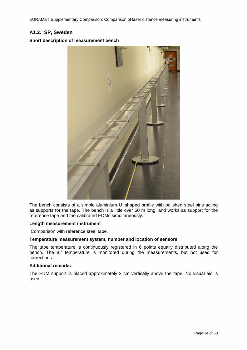
EURAMET Supplementary Comparison Comparison of laser distance measuring instruments
Page 34 of 60
A12 SP Sweden
Short description of measurement bench
The bench consists of a simple aluminium Uminusshaped profile with polished steel pins acting as supports for the tape The bench is a little over 50 m long and works as support for the reference tape and the calibrated EDMs simultaneously
Length measurement instrument
Comparison with reference steel tape
Temperature measurement system number and location of sensors
The tape temperature is continuously registered in 6 points equally distributed along the bench The air temperature is monitored during the measurements but not used for corrections
Additional remarks
The EDM support is placed approximately 2 cm vertically above the tape No visual aid is used
EURAMET Supplementary Comparison Comparison of laser distance measuring instruments
Page 35 of 60
A13 AS Metrosert Estonia
Short description of measurement bench
The 21-m bench is located in the designated corridor-like laboratory room The lab is air-conditioned and the stability of temperature is typically plusmn05 ordmC There are three humidity and temperature sensors in room for stability and gradient monitoring
Two stainless steel rails running in parallel are made of 3-m long rods The rails lay without fixed attachment on metal supports which are mounted on concrete base The base rests on pillars made of bricks
Length measurement instrument
Laser-interferometer system Renishaw ML10 was used as length measurement instrument
Laser interferometer gets temperature humidity and pressure data from itrsquos own measurement system EC10
Additional remarks
Due to the length of the bench only measurements up to 20 m could be made Five measurement series were made with each EDM
EURAMET Supplementary Comparison Comparison of laser distance measuring instruments
Page 36 of 60
A14 PTB Germany
Short description of measurement bench
The measurements were performed on the 50 m geodetic base of the PTB The comparator consists of a 50 m rail The laboratory is equipped with a network of 21 temperature sensors spaced by 25 m along the bench As depicted in fig 1 the EDM is mounted at one end of the comparator the reflector is fixed vertically on the carriage A large retroreflector is mounted approximately 150 mm below the EDM reflector on the carriage reflecting the beam of the reference interferometer The deviation of the length due to tilting carriage (Abbe error) has been investigated along the bench by comparison of two interferometers It remains smaller than 100 microm The distance of the first position of 300 mm with respect to the back side of the EDM is determined by a gauge block of 300 mm length and a thickness of 10 mm This procedure is depicted for one of the comparison standards in figure 2
For the calibration the desired positions are programmed After the carriage reaches a measurement position the operator waits for another 30 s for the carriage to settle In control experiments the remaining movement between positioning and measurement remained smaller than 2 microm The operator then activates the measurement of the EDM reads the indicated position and writes it down The procedure is repeated for twelve times at every position the mean of the 12 measurements represents the ldquoindicated distance by the EDMrdquo All measurements of a single run at one position are performed within approximately one minute The complete measurement was repeated for four times
Length measurement instrument
The reference length is determined by a frequency-calibrated laser interferometer (Agilent 5519A) The reference interferometer is set up in Michelson geometry the signals being digitalised by a Heidenhain IK 121 card The index of refraction is determined by the external weather station of the geodetic base consisting of 21 Pt-100 temperature sensors spaced 25 m along the bench two humidity sensors (Testo 650) and two pressure sensors (Setra 370 and DPI 141) The environmental parameters are used to determine the index of refraction for the reference measurement deploying the modification of the Edleacuten equation by Boumlnsch and Potulski
EURAMET Supplementary Comparison Comparison of laser distance measuring instruments
Page 37 of 60
A15 CMI Czech Republic
Description of measurement bench
The EDMs were measured on 30 m long measuring bench equipped by laser interferometer (LI) Renishaw ML10 (pic 1 and 2) calibrated traceable to national standard of length and quantities of environmental sensors The target plate and retroreflector of the LI were fixed on a moving part of the bench and each EDM was fixed in horizontal position by clamps (pic 3) LI and EDM are placed on opposite ends of bench the Abbe offset was lt10 mm for some of them and lt50mm for all The value of LI was reset (to zero) at position corresponding to the rear of the EDM (using 3D measuring arm FARO Quantum with uncertainty about 27microm) The perpendicularities of the EDM stop as well as target plate to the beam were also checked by FARO) Each EDM was 3x replaced and aligned the measurement (reading) was repeated 6 times for each alignment and position the mean value of these 3x6 measurements is stated in tables with results The uncertainty claimed covers the statistical uncertainty of single readings Only in case of Leica D8 (the best performing EDM in this comparison) we state also the uncertainty corresponding to the mean of 6 readings in last column (this uncertainty is smaller and better illustrates our CMC)
Length measurement instrument
- Laser interferometer Renishaw - Laser 633 nm Type ML10 - Compensator EC10 - 3D measuring arm FARO Quantum - 3D measuring arm FARO Quantum
EURAMET Supplementary Comparison Comparison of laser distance measuring instruments
Page 38 of 60
A16 SMU Slovakia
Short description of measurement bench
No bench is available at the SMU the measurements are being carried out in the underground corridor of the laboratory building with length of 428 m
The 50 m steel measuring tape KINEX was used as the reference laid on the floor and pulled by the force 50 N (the same force as had been applied during its calibration at the SMU) The calibration of reference tape was done at the SMU using ULM3m Zeiss with laser interferometer Agilent 5529 B (ie per 3 m parts)
Three mercury thermometers with the resolution of 01 degC were used along the measurement path each of them laid onto the tape and located at 667 m 1990 m (instead of 20 m because of this was one of measuring points) and 333 m respectively Each of them thus corresponded approximately to one third of the measured steel tape section
Regarding the 03 m measuring point the ULM3m Zeiss length measuring machine was used with the 300 mm gauge block as the reference
Length measurement instrument
We used our own target plate being fixed perpendicularly (within uncertainty stated) to the construction equipped with nonius and the camera holder transported manually along the steel tape The second construction was fixed to the tape by such a way that zero line of the tape corresponded to the rear of EDM (within uncertainty stated)
The position of the target is read on the monitor and 20 repeated readings of the EDM data took place in each measuring point (multiples of 5 m up to 40 m)
Concerning 03 m the 300 mm gauge block was fit between the target plate and the construction with EDM The distance of the EDM rear from the target plate corresponded to the length of gauge block (within uncertainty stated)
Additional remarks
The identical measurement method was used as we use to do within our calibration service although the results reporting is different ndash we provide the regression line calculated from the measurement of irregularly distributed points and corresponding uncertainty (k = 2) in the form of [a bL] mm (ie the same coefficients for each length in the range (0 ndash 42) m)
SMU hasnrsquot got this category in CMC tables
EURAMET Supplementary Comparison Comparison of laser distance measuring instruments
Page 39 of 60
A17 INM Romania
Short description of measurement bench
Geodesic base located in the basement of the laboratory with nominal length equal to 50 m having a mobile carriage thet support both laser He-Ne retroreflector and the target of the laser distance measuring instrument in the front of geodesic base exists a support where are aligned both laser interferometer and the laser distance measuring instruments
Length measurement instrument
Laser interferometer type Hewlett Packard model 5526 A with nominal length equal to 50 m resolution 0001 mm
U = 02 microm +0510-6L
Additional remarks
During the measurements the maximum gradient of temperature was equal to 05 degC
EURAMET Supplementary Comparison Comparison of laser distance measuring instruments
Page 40 of 60
A18 INRIM Italy
Short description of measurement bench
The facility for long distance measurements is located in a corridor of the gallery devoted to dimensional metrology The structure consists in a 28 m long rail fixed to a series of pillars which rest directly on the ground released from the vibrations of floor and wall The measuring system is based on a heterodyne interferometer whose mobile arm consists of a hollow retro-reflector mounted on a structure that can run along the rail so-called carriage A photograph of the facility is presented in Fig1
The carriage is moved by a micro-step motor the motor driver receives a digital pulse and converts it into an electrical pulse to run the motor Each pulse causes a rotation of the motor shaft of one step which amounts to 11000 of a complete revolution of the shaft If the pulse frequency increases the rotation becomes continuous with a speed that is directly proportional to the pulse frequency The speed ranges between few microms up to 27 ms with a resolution of 03 microms
Since the carriage must move back and forth automatically for a distance of almost 30 m a remote control to send pulses to the motor driver was implemented It consists of two parts a radio command which allows to set some general parameters of the carriage movement such as the movement direction and mode of travel (slow or fast) and a fast command which is performed by an amplitude modulated laser beam placed at the beginning of the track oriented towards the carriage A photo detector placed above the carriage receives the modulated laser beam which is transformed into pulses to be sent to the driver of the motor The modulation of the laser beam is implemented by a LabView program that controls a digital output of the data acquisition device
Length measurement instrument
The length measurement instrument is based on a heterodyne incremental interferometer The main beam of the interferometer with frequency f1 is generated by a frequency stabilized
EURAMET Supplementary Comparison Comparison of laser distance measuring instruments
Page 41 of 60
He-Ne laser calibrated with respect to the INRIM length standard and sent to the measurement arm the second beam is a portion of the first one diffracted by an acousto-optic modulator (AOM) with frequency f2 = f1 + 80 MHz The reference detector acquires the beat note signal at 80 MHz while the measurement detector acquires a signal at 80 MHz whose phase is varied due to the displacement of the retro-reflector moving on the rail In figure 2 the optical design of the interferometer is presented
Two different measuring techniques have been implemented
1 the ldquophase measuringrdquo technique based on fringes counting with a relative uncertainty of 5middot10-7 but limited at the maximum carriage speed of 3 cms
2 the ldquoDoppler frequency measurementrdquo technique for higher carriage speed based on the measurement of the Doppler frequency shift while the carriage runs
The second technique was validated by means of the comparison with the first technique at low speed with an agreement of the order of 3middot10-6 hence the Doppler frequency method could be considered validated within 01 mm over the whole rail path with the advantage of reducing the time needed to cover long distances so it was used for the EDM comparison
In order to obtain the distance covered by the carriage according to technique 2 the Doppler frequency is measured by a commercial high-performance counter (a Pendulum CNT-90) without dead time based on time stamping then it is converted in speed and integrated over time according to the following formula
( ) ( )int minus=minus= tffn
dtn
ffdairair
λλ
2
1
2
1
where d is the distance covered by the carriage f is the frequency of the measuring signal with the carriage at rest frsquo the frequency of the measuring signal with the carriage moving λi
is the wavelength of the laser in vacuum n - air is the air refractive index and ti is the integration time The difference frsquo-f is just the Doppler frequency due to the moving carriage
The time interval measurement resolution of the instrument is 100 ps and the time base is
EURAMET Supplementary Comparison Comparison of laser distance measuring instruments
Page 42 of 60
connected to the INRIM UTC so that the measurements of the Doppler frequency and the integration time are extremely accurate The environmental parameters such as air temperature atmospheric pressure partial pressure of water were monitored during the measurement process in order to calculate the value of air refractive index according to the Edlenrsquos formula
Comparison set-up
The different technical solutions adopted for the EDMs and for the target plate positioning are discussed in this paragraph and sketched in figure 3
Fig 3 picture of the EDM and target positioning area
Target plate positioning
In order to use the provided target plate an ad-hoc mounting was manufactured at INRIM it consists in a sort of picture frame made in aluminum which slightly clamps the target folded in half and gives it the necessary stiffness to be a reproducible target The upper part of the frame is L-shaped and allows it to be fixed to the carriage structure by means of two screws The rear part of the target mounting is depicted in figure 4 The target mounting was considered necessary because of the poor stiffness and planarity of the plastic target With the aluminium frame a planarity better than 01 mm was guaranteed The target plate is placed few centimetres next to the retro-reflector and normal to the interferometer beam axis since the EDM laser should be as close and parallel as possible to the reference beam
EURAMET Supplementary Comparison Comparison of laser distance measuring instruments
Page 43 of 60
Fig 4 picture of the rear part of the target plate mounting
EDMsrsquo positioning
The EDMs are placed on a cradle-like platform which is able to adjust the inclination of the EDM along the longitudinal axis (pitch angle) The platform height allows the EDMs to be at approx the same height as the interferometer beam A crucial role was played by the stop-wall placed behind the platform since it represents the ldquozero pointrdquo for all the length measurement Hence a particular effort was devoted to align the stop-wall so that it was normal to the interferometer beam axis and parallel to the target plate
Fig 5 detail of EDMsrsquo positioning the cradle-like platform and the stop-wall are well visible
EURAMET Supplementary Comparison Comparison of laser distance measuring instruments
Page 44 of 60
Target and stop-wall alignment
In order to have the stop-wall parallel to the target plate and normal to the interferometer beam axis the following procedure has been used
1) the stop-wall and the target plate were roughly placed trying to set them parallel and normal to the rail by eye (ie within few millimeters)
2) in order to check if the target was normal to the rail one EDM was positioned on the platform the pitch and yaw angles of the EDM were adjusted by observing the position of the EDM laser spot on the target plate when the target is moved along the rail fixed position means laser beam parallel to the carriage movement Then the target was moved until the end of the rail and a thin mirror was kept in contact with it hence observing the EDM laser reflected by the mirror it was possible to adjust the target tilt acting on the screws until the laser beam is reflected back to the source
3) finally in order to check the parallelism between the stop-wall and the target a tool made by a laser pointing orthogonally to its base was used the base was leant against the stop-wall and the laser was centered on the target when the target is near then the target was moved until the end of the rail hence observing the spot of the laser on the target it was possible to adjust the stop-wall orientation
The residual misalignment errors which we were not able to eliminate were kept into account in the uncertainty budget
Measurement of the first 30 cm
Due to the geometry of our set-up it was not possible to perform the first point of measurement by means of the interferometer indeed the carriage (hence the target) is not able to go in contact with the stop-wall
Fig 6 measurement of the first 30 cm the ruler touching the stop-wall and the target and the mechanical probe (in the back) touching the carriage are visible
EURAMET Supplementary Comparison Comparison of laser distance measuring instruments
Page 45 of 60
So a ruler made of aluminum with rounded ends and nominal length equal to 30 cm was adopted to set the distance between the target plate and the stop-wall for the first point of measurement as it is shown in figure 6 The ruler whose length was measured by a CMM machine was inserted between the target and the stop-wall leaning against the latter and the carriage was carefully moved towards the stop-wall until the target lightly touched the ruler A mechanical probe that touches the carriage structure when carriage is in the ldquo30 cmrdquo position was used as a reference measurement to check the repeatability of this distance after each measurement set
Fig 7 detail of the mechanical probe touching the carriage
Environmental parameters
The environmental parameters such as air temperature atmospheric pressure and humidity were monitored during the whole measurement process in order to calculate the value of air refractive index according to the Edlenrsquos formula
Among these parameters the temperature distribution along the mobile arm of the interferometer was our main concern mainly for two reasons
1 the temperature control of the gallery was not perfectly working during the measurement period so temperature drifts had to be monitored
2 longitudinal temperature gradients due to non uniform heating and to the presence of electronic instruments were pretty high
To the purpose 14 thermometers were uniformly dislocated along the rail and automatically recorded for all the measurement period Both temporal drifts and gradients along the path have been taken in account in the uncertainty budget In any case maximum temperature differences along the rail are within 1 degC In fig 8 an extract from the acquisition file is shown
Unfortunately the air conditioning system did not work well during the measurement campaign hence the measurements were performed at a mean temperature of 209 degC
EURAMET Supplementary Comparison Comparison of laser distance measuring instruments
Page 46 of 60
Fig 8 each curve represents the temperature distribution along the rail during the measurements campaign
Carriage waving
Since the rail is not perfectly straight and the measurement laser is not coincident with the measurement beam the Abbegrave error due to waving of the target must be considered A quantitative measurement and a qualitative measurement were carried out With an electronic level placed on the carriage the straightness on the vertical plane has been mapped with a half meter resolution (the data are reported in fig 9) With a laser placed on the carriage the horizontal and vertical waving are qualitatively compared by looking at the movements of the light spot on a target fixed to the rail end As a conclusion the horizontal and vertical waving are comparable in magnitude and the peak to peak error is of the order of 300 arcseconds
Fig 9 vertical waving of the target measured by an electronic level placed on the carriage
EURAMET Supplementary Comparison Comparison of laser distance measuring instruments
Page 47 of 60
Measurement procedure
The measurements were carried out according to the following procedure
The target was set in the starting position with the procedure described above
In sequence the four EDMs are positioned on the base the horizontal and vertical tilt are adjusted and the distance measurement is recorded An additional fifth EDM (Bosh DLE 150 property of INRiM) was included in the measurement sequence Each EDM is placed on the base and gently pushed against the reference wall in such a way that the measurement laser beam starting point is the same for all EDMs Than the horizontal and vertical angles were adjusted in order to hit the central point of the target indicated with two black marks (see pictures 3 and 6) with ldquovisualrdquo alignment The measurement button is then pressed several times (typically 5) and the average reading is recorded Typical dispersion between readings is within few last digit units In case the dispersion between readings is too large the anomaly is recorded
The carriage was then moved in the next position (about 5 m) and the measurement sequence was repeated for the 5 EDMs The operation is repeated up to 25 m The 25 m measurement is than repeated again as well as all the points till the first one so that each point is measured twice each set Since the carriage movement is ldquoopen looprdquo the positioning of the carriage was not exactly in the nominal 5 m intervals For each positioning the incremental displacement is measured by the interferometer in the Doppler mode Finally the measured values were averaged in order to give a single value for each nominal position
At the end of the measurement set when the carriage is at the 30 cm position again the sum of the interferometric measurements should be very close to zero The residual value is compared with the difference between the first and the final measurements of the mechanical probe The difference must be within the uncertainty of the Doppler technique otherwise some error occurred in the measurement set that must be repeated
At the end of the session 10 complete sets of measurements recorded from the 20th to the 30th of January 2012 have been considered for this report
Additional remarks
Effect of laser pointing
During a preliminary set of measurements we noticed a strong and unexpected dependence of the measurement result on the position of the laser spot on the target Indeed since no particular instructions were given about the relative position of the laser spot on target position (except to exclude the central joint between the two halves) we decided to work relatively close to the right side of the target -closer to the interferometer beam- in order to reduce the Abbegrave error We noticed very large errors at large distances in particular of the Leica DISTO D3a (see figure 10)
EURAMET Supplementary Comparison Comparison of laser distance measuring instruments
Page 48 of 60
Fig 10 errors of each EDM In a preliminary set of measurements
We also noticed that this error was strongly dependent on the position of the spot on the target For this reason we carried out a set of measurements at the maximum length in different positions of the target from one edge to the other according to figure 11 The results are reported in table V
EDM A B C D E
Leica D3a -4 +1 0 +24 +43
+2 0 +42 +40
-1 0 +38
Leica D8 0 0 0 2 +7
0 +12 +23
table V deviations (in mm) from the length measured at point C aiming the laser spot at different positions of the target (notations as in figure 11)
We tried to find an explanation to this effect in the shape of the laser spot if the spot was
EURAMET Supplementary Comparison Comparison of laser distance measuring instruments
Page 49 of 60
particularly defocused or had high diffraction some of the energy could fall out of the target and affect the measurement result In fact the images of the spots (shown in fig 12) do not support this hypothesis Finally we decided to use the center of the (half) target for the comparison
Changing the target
In order to investigate the influence of the target on the measurements a cardboard foil (400 x 400) mm was fixed to the target mounting and a complete set of measurements was performed The results reported in figure 13 and 14 do not show any evidence of a possible dependency of the EDM measurement on the target kind
EURAMET Supplementary Comparison Comparison of laser distance measuring instruments
Page 50 of 60
Measurement at 50 m
Although we are not able to perform traceable length measurements beyond 28 m we wanted to get a sense of EDMs behaviour at longer distances So a target (represented by a rack side wall) was placed at approximately 50 m one after the other the EDMrsquos were positioned on the base and pointed towards the target The measurements were repeated then the target was replaced by the target used for the comparison and a third set of measurements were performed To our great surprise all the EDMrsquos were in good agreement (within 2 or 3 mm for each set of measurement) even those which showed errors of the order of five to ten millimeters at 25 m namely BOSCH DLE 50 and LEICA DISTO D3a Therefore each set of measurements was averaged and the deviations from the mean value are reported in figure 15
EURAMET Supplementary Comparison Comparison of laser distance measuring instruments
Page 51 of 60
Fig 15 Deviations from average value of the measurements At 50 m
EURAMET Supplementary Comparison Comparison of laser distance measuring instruments
Page 52 of 60
A19 CEM Spain
Short description of the measurement bench
To make the measurements of EDMs we have used a reference line made of adjustable supports fixed on a wall of the laboratory Each support is nominally separated five metres from the previous one so we can generate reference lengths up to fifty metres with a pitch of five metres The supports are designed to accommodate both targets and handheld EDMs Distances between supports were measured by using a total station traced to national standards The relative angles of the bases have been measured and corrected
Fig 1 - View of three consecutive supports of the 50 m baseline (left) Lab technician situating an EDM on the first support of the baseline (right)
Length measurement instrument
The baseline was calibrated by using a total station Leica TDA5005 with spherical reflector the calibration uncertainty being 02 mm for k = 2
The target is provided by the comparison The quality of the target was judged as not good due to geometrical constructive errors and the lack of rigidity and stability We measured the flatness of the target surface the distance edge-surface and the angle between them by using a 3D coordinate measuring machine The results of flatness and angle were included in the uncertainty budget and the distance EDM-target was corrected for each EDM due to each beam impinged on a different point of the target
We were not able to measure the distance 0 to 03 m because the baseline pitch is 5 meters and although we are able to measure shorter values in a different facility the target was not appropriate for our bench
EURAMET Supplementary Comparison Comparison of laser distance measuring instruments
Page 53 of 60
Fig 2 - View of an EDM on the first support of the baseline (left) A closer look showing the support adjustments and the origin plate (right)
Fig 3 - View of the comparison target on one of the supports of the baseline (left) A closer look showing the target edge against the support rigid reference (right)
Measurement method
The measurements were carried out by comparison against the known values of the calibrated baseline (metallic references on supports)
Environmental conditions were maintained within the following limits
- Temperature 20 ordmC plusmn 05 ordmC
- Humidity 45 plusmn 10
Each laser distance measuring instrument was placed at the first support of the base and aligned so that the laser beam was perpendicular to the target as indicated by the comparison protocol
For each measurement we took the average of thirty measurements It permitted us to evaluate the repeatability of the instrument
EURAMET Supplementary Comparison Comparison of laser distance measuring instruments
Page 54 of 60
A110 BEV Austria
Short description of the measurement bench
Fig 1 Carriage of tape bench View from the laser interferometer side Retroreflector mounted on the vertical plate the EDM target is mounted on the backside
Fig 2 Support for the DUT Adjustable with 2 translational and 2 rotational degrees of freedom respectively
Fig 3 Setting of the 300 mm starting position Note the rough-and-ready mounted target plate
Fig 4 Laser interferometer side of the bench The DUT is 50 m away on the other side
EURAMET Supplementary Comparison Comparison of laser distance measuring instruments
Page 55 of 60
Measurement procedure 1 The EDM is positioned with the help of a 4-axis positioning stage so that its laser beam is
coaxial with the measurement direction of the laser interferometer (in head on configuration)
2 The EDM is removed from its support The bench carriage is positioned so that the distance of the target plate from the EDM back support is 300 mm A length bar with spherical faces is used for this adjustment The laser interferometer is preset to 300 mm and the EDM is put back on its support
3 At each position 10 consecutive measurements are taken (repeatability) and the carriage is moved to the next position The carriage is manually moved under control of the laser interferometer until it is within plusmn30 microm at the correct position (Exception for the DLE 150 the target is not positioned at 10 m but at 10 m ndash 1 mm to make use of the higher resolution) The indicated (not the nominal) distance of the laser interferometer is recorded for the determination of the deviation
4 After reaching the 50 m position all points are measured in reverse order (bidirectional) Immediately after the last measurement the EDM is removed and the indication using the 300 mm length bar is checked (thus noting a possible drift of the setup)
5 Each instrument was measured 4 times according to this procedure on different days (reproducibility of bench and instrument)
Length measurement instrument
Agilent laser interferometer with long range option The bench was completed short time before performing these measurement So the characterisation was not complete and the respective measurement uncertainty of the laser interferometer is estimated rather high But anyway its contribution to the overall uncertainty can nearly be neglected
Additional remarks
The uncertainty originating from the DUT is the dominating uncertainty contribution Specifically the resolution of the two Bosch instruments (1 mm) and the repeatability are the largest contributions For the DLA 50 the pooled standard deviation of a reading at 50 m is larger than 2 mm Moreover the length dependence is not a simple function
All of the instruments show a significant deviation of the laser beam from the normal of the back (reference) face of the instrument The measured angles reach from 04deg (D3a) to 11deg (DLE 50) This leads depending on the outer dimensions of the instruments to a constant uncertainty contribution of 02 mm in our setup It must be noted that the reference faces are not well defined in most of the instruments
The reproducibility is quite different for the four instruments so only part of it originates from the setup For CMC claims we will use the standard uncertainty value of the most reproducible instrument (D3a) which amounts to 013 mm For an ideal instrument with a resolution of 01 mm and perfect repeatability we would thus have a constant expanded uncertainty of 053 mm up to 50 m
EURAMET Supplementary Comparison Comparison of laser distance measuring instruments
Page 56 of 60
A111 JV Norway
Short description of measurement bench
EDM under calibration and the reference system are aligned along a 50 m measurement bench with rails to carry the linear movement of a target plate for the EDM and a corner cube reflector for the reference system The distance between parallel axis of EDM and axis of the reference system is 130 mm Abbe error due to angle errors for the movement is smaller than 01 mm and is corrected for at each measurement point At long lengths an aperture is used approximately midway between the target plate and the EDM to avoid interfering stray light to the EDM
Alignment procedure
1) Alignment of reference system to the movement of the carriage (rails)
2) Alignment of the EDM to the movement of the carriage (rails)
3) Alignment of a plane mirror at the position of the target plate using back-reflection to the EDM output (normal incident of light on the mirror)
4) Take out the EDM and align the zero reference plate at the back of the EDM to the plane mirror
5) The mirror is replaced by the target plate and the target plate is aligned to the zero reference plate
6) Zero setting of the reference measurement system when target plate is at zero distance to the reference plate at the back of the EDM
7) Put the EDM back in position and realign it to the movement of the carriage (rails)
8) Zero setting of the EDM to the reference plate
Image 1) Image 2) Image 3) Image 4)
Image 1) Items 5) ndash 6) in alignment procedure
Fixture for HP linear interferometer is seen bottom right Part of Wyler instrument is seen to the left blue colour
Image 2) Items 7) and 8) in alignment procedure
Micrometer screws for angle alignment in two directions and linear translation for zero setting of the EDM Push button on the EDM is positioned at the tilting point of the angle adjustment table to maximize stability during measurement HP 5519 A laser head is seen to the right
Image 3) Ready to measure at selected distances from zero point the reference plate
Image 4) EDM spot size at 50 m
Length measurement instrument
- Hewlett Packard Dynamic Calibrator 5519 A (max range 80 m)
- Pressure air temperature humidity Vaisala
EURAMET Supplementary Comparison Comparison of laser distance measuring instruments
Page 57 of 60
- Digital high resolution angle measurement Wyler
I used our own target plate which is of the same type as enclosed in the artefact suitcase article number 766560 from Leica but with reduced size width x hight = 90 x 137 mm
The zero reference plate is of similar type and size
Before measurements batteries of EDMs were switched to new batteries Old batteries are switched back after calibration
For L gt 5 m an aperture of similar size as the target plate is used approximately midway between the EDM and the target plate
Additional remarks
Reports on EDM indicated values at each measurement point is the average value of n = 5 repetitions A linear model of the standard deviation for the repeatability of the EDM readings at different lengths is estimated using m = 20 repetitions at least 5 positions along the scale An estimate of the length dependent repeatability is made for each instrument
The expanded uncertainty U(95) is rounded up to the limiting resolution of 1 mm in the interval 10 m to 40 m for Bosch GLM 150
After the calibration we also estimated the angle error of the optical axis of the EDM to its back plane (back reference of EDM) Bosch DLE 50 26 mrad up measured at 50 m Bosch GLM 150 8 mrad to the left measured at 50 m Leica DISTO D3a 37 mrad down measured at 20 m Leica DISTO D8 2 mrad to the left and 4 mrad down (45 mrad total) measured at 20 m
The distance between parallel walls will be measured too large if the back plane is assumed to be normal to the optical axis of the EDM by ∆LL = (1cosα ndash 1) Bosch DLE 50 ∆LL = 340 ppm (∆L = 17 mm at L = 50 m) Bosch GLM 150 ∆LL = 32 ppm (∆L = 16 mm at L = 50 m) Leica DISTO D3a ∆LL = 7 ppm (∆L = 034 mm at L = 50 m) Leica DISTO D8 ∆LL = 10 ppm (∆L = 05 mm at L = 50 m)
EURAMET Supplementary Comparison Comparison of laser distance measuring instruments
Page 58 of 60
A112 METAS Switzerland
Short description of measurement bench (photo recom mended)
50 m bench with laser interferometer (see photo detailed description in Michel Degoumois Un Long laboratoire de mesure OFMETinfo Vol5 No 2 1998)
Length measurement instrument
HP 5529 B laser interferometer range 80 m
EURAMET Supplementary Comparison Comparison of laser distance measuring instruments
Page 59 of 60
A113 GUM Poland
Short description of measurement bench
The 50 m bench is situated in the corridor laboratory located in the basement and has its own air conditioning system with air temperature 20 plusmn 1 degC and humidity 50 plusmn 10 RH The measuring carriage is carried microscope with CCD camera and the optics associated with the interferometer The carriage is driven using belt-transmission and electrical engine with remote ndash controlled variable speed drive
The EDM was placed on the fixed adjustable plate on the other end than laser interferometer The target plate of the EDM was placed on the measuring carriage For each EDM 3 series of measurement were done Before the each measurement EDM was repositioned and aligned again
Length measurement instrument
1 Laser interferometer HP 5529A with long-range option laser head HP 5519A
2 Ambient measurement system number and location of sensors - 20 air temperature sensors type YSI with KEITHLEY multimeter they are placed very
close to axis of the laser beam - air pressure and humidity are measured with Vaisala barometer and
thermohigrometer - CO2 content was measured with analyzer made by Intelli Charge type SPN 4462
EURAMET Supplementary Comparison Comparison of laser distance measuring instruments
Page 60 of 60
Appendix 2 Corrections of reports
131 CEM Spain
CEM reported two errors in their report
1) Bosch GLM 150 EDM error for 35 m should be -08 mm instead of the indicated 08 mm
2) Leica DISTO D8 EDM error for 35 m should be -019 mm instead of the indicated 019 mm
Proposed corrections have been included in Tables 2 and 4 of the Final Report
132 AS Metrosert Estonia
AS Metrosert reported mixed up of all results for Bosch DLE 50 and Bosch GLM 150 The results and uncertainties sent for DLE 50 was results for GLM 150 and vice versa
Proposed corrections have been included in Tables 1 and 2 of the Final Report
133 INRIM Italy
Among the data reported from INRIM some anomalies were found in the measurements of BOSCH DLE 50 and LEICA DISTO D3a at distances of 20 and 25 m
After preliminary discussion on Draft A it was understood that those anomalies could be explained as a sensitivity of said instruments to the laser light that once diffused by the target is reflected by surfaces parallel to the measurement axis and detected together with the wanted signal The superimposition of the two signals can cause a ldquopullingrdquo effect leading to an overestimation of the distance being the reflected path always longer than the direct one Indeed in the INRIMrsquos set-up the target was mounted pretty close to the flat rail used for the carriage movement being likely responsible for unwanted reflections that disturbed the measurements
Since the errors reported in INRIMrsquos measurements can be ascribed to a defect of BOSCH DLE 50 and LEICA DISTO D3a andor to a lack of description of the working conditions of said instruments INRIM asked to eliminate its measurement points at 20 and 25 m of said instruments from the comparison
Proposed corrections have been included in Tables 1 and 3 of the Final Report
134 JV Norway
Justervesenet has changed the procedure and introduced two apertures instead of only one aperture (iris) which was positioned at half distance between EDM and target The reason is that the reference beam also has an aperture and it is positioned right below the beam from the EDM (130 mm distance between axes) Some diffusively reflected stray light from the EDM target might enter the aperture for the reference beam reflect at the measurement table and reach the detector of the EDM In our calibration set-up we have only seen problems at L gt 30 m We will position the first aperture at ca 5 m from the EDM and then the second aperture at ca 25 m This combination of two apertures will effectively eliminate interference of stray light from the measurement table to the EDM detector for all lengths up to 50 m
Justervesenet also increases the uncertainty component regarding repeatability reproducibility so that the expanded uncertainty increases from 14 mm to 15 mm
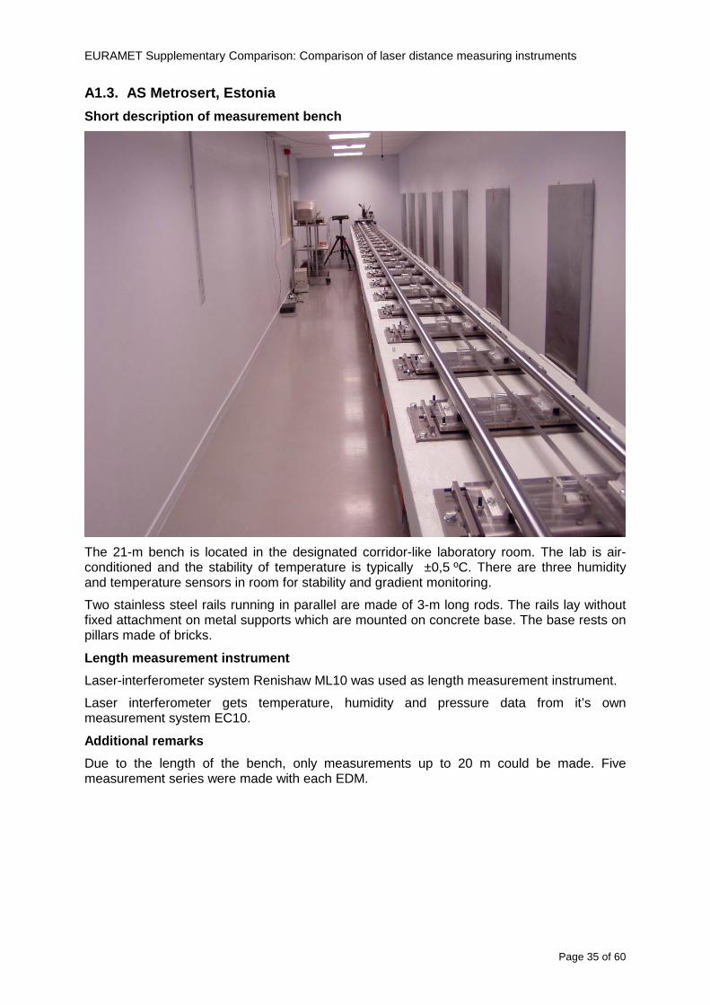
EURAMET Supplementary Comparison Comparison of laser distance measuring instruments
Page 36 of 60
A14 PTB Germany
Short description of measurement bench
The measurements were performed on the 50 m geodetic base of the PTB The comparator consists of a 50 m rail The laboratory is equipped with a network of 21 temperature sensors spaced by 25 m along the bench As depicted in fig 1 the EDM is mounted at one end of the comparator the reflector is fixed vertically on the carriage A large retroreflector is mounted approximately 150 mm below the EDM reflector on the carriage reflecting the beam of the reference interferometer The deviation of the length due to tilting carriage (Abbe error) has been investigated along the bench by comparison of two interferometers It remains smaller than 100 microm The distance of the first position of 300 mm with respect to the back side of the EDM is determined by a gauge block of 300 mm length and a thickness of 10 mm This procedure is depicted for one of the comparison standards in figure 2
For the calibration the desired positions are programmed After the carriage reaches a measurement position the operator waits for another 30 s for the carriage to settle In control experiments the remaining movement between positioning and measurement remained smaller than 2 microm The operator then activates the measurement of the EDM reads the indicated position and writes it down The procedure is repeated for twelve times at every position the mean of the 12 measurements represents the ldquoindicated distance by the EDMrdquo All measurements of a single run at one position are performed within approximately one minute The complete measurement was repeated for four times
Length measurement instrument
The reference length is determined by a frequency-calibrated laser interferometer (Agilent 5519A) The reference interferometer is set up in Michelson geometry the signals being digitalised by a Heidenhain IK 121 card The index of refraction is determined by the external weather station of the geodetic base consisting of 21 Pt-100 temperature sensors spaced 25 m along the bench two humidity sensors (Testo 650) and two pressure sensors (Setra 370 and DPI 141) The environmental parameters are used to determine the index of refraction for the reference measurement deploying the modification of the Edleacuten equation by Boumlnsch and Potulski
EURAMET Supplementary Comparison Comparison of laser distance measuring instruments
Page 37 of 60
A15 CMI Czech Republic
Description of measurement bench
The EDMs were measured on 30 m long measuring bench equipped by laser interferometer (LI) Renishaw ML10 (pic 1 and 2) calibrated traceable to national standard of length and quantities of environmental sensors The target plate and retroreflector of the LI were fixed on a moving part of the bench and each EDM was fixed in horizontal position by clamps (pic 3) LI and EDM are placed on opposite ends of bench the Abbe offset was lt10 mm for some of them and lt50mm for all The value of LI was reset (to zero) at position corresponding to the rear of the EDM (using 3D measuring arm FARO Quantum with uncertainty about 27microm) The perpendicularities of the EDM stop as well as target plate to the beam were also checked by FARO) Each EDM was 3x replaced and aligned the measurement (reading) was repeated 6 times for each alignment and position the mean value of these 3x6 measurements is stated in tables with results The uncertainty claimed covers the statistical uncertainty of single readings Only in case of Leica D8 (the best performing EDM in this comparison) we state also the uncertainty corresponding to the mean of 6 readings in last column (this uncertainty is smaller and better illustrates our CMC)
Length measurement instrument
- Laser interferometer Renishaw - Laser 633 nm Type ML10 - Compensator EC10 - 3D measuring arm FARO Quantum - 3D measuring arm FARO Quantum
EURAMET Supplementary Comparison Comparison of laser distance measuring instruments
Page 38 of 60
A16 SMU Slovakia
Short description of measurement bench
No bench is available at the SMU the measurements are being carried out in the underground corridor of the laboratory building with length of 428 m
The 50 m steel measuring tape KINEX was used as the reference laid on the floor and pulled by the force 50 N (the same force as had been applied during its calibration at the SMU) The calibration of reference tape was done at the SMU using ULM3m Zeiss with laser interferometer Agilent 5529 B (ie per 3 m parts)
Three mercury thermometers with the resolution of 01 degC were used along the measurement path each of them laid onto the tape and located at 667 m 1990 m (instead of 20 m because of this was one of measuring points) and 333 m respectively Each of them thus corresponded approximately to one third of the measured steel tape section
Regarding the 03 m measuring point the ULM3m Zeiss length measuring machine was used with the 300 mm gauge block as the reference
Length measurement instrument
We used our own target plate being fixed perpendicularly (within uncertainty stated) to the construction equipped with nonius and the camera holder transported manually along the steel tape The second construction was fixed to the tape by such a way that zero line of the tape corresponded to the rear of EDM (within uncertainty stated)
The position of the target is read on the monitor and 20 repeated readings of the EDM data took place in each measuring point (multiples of 5 m up to 40 m)
Concerning 03 m the 300 mm gauge block was fit between the target plate and the construction with EDM The distance of the EDM rear from the target plate corresponded to the length of gauge block (within uncertainty stated)
Additional remarks
The identical measurement method was used as we use to do within our calibration service although the results reporting is different ndash we provide the regression line calculated from the measurement of irregularly distributed points and corresponding uncertainty (k = 2) in the form of [a bL] mm (ie the same coefficients for each length in the range (0 ndash 42) m)
SMU hasnrsquot got this category in CMC tables
EURAMET Supplementary Comparison Comparison of laser distance measuring instruments
Page 39 of 60
A17 INM Romania
Short description of measurement bench
Geodesic base located in the basement of the laboratory with nominal length equal to 50 m having a mobile carriage thet support both laser He-Ne retroreflector and the target of the laser distance measuring instrument in the front of geodesic base exists a support where are aligned both laser interferometer and the laser distance measuring instruments
Length measurement instrument
Laser interferometer type Hewlett Packard model 5526 A with nominal length equal to 50 m resolution 0001 mm
U = 02 microm +0510-6L
Additional remarks
During the measurements the maximum gradient of temperature was equal to 05 degC
EURAMET Supplementary Comparison Comparison of laser distance measuring instruments
Page 40 of 60
A18 INRIM Italy
Short description of measurement bench
The facility for long distance measurements is located in a corridor of the gallery devoted to dimensional metrology The structure consists in a 28 m long rail fixed to a series of pillars which rest directly on the ground released from the vibrations of floor and wall The measuring system is based on a heterodyne interferometer whose mobile arm consists of a hollow retro-reflector mounted on a structure that can run along the rail so-called carriage A photograph of the facility is presented in Fig1
The carriage is moved by a micro-step motor the motor driver receives a digital pulse and converts it into an electrical pulse to run the motor Each pulse causes a rotation of the motor shaft of one step which amounts to 11000 of a complete revolution of the shaft If the pulse frequency increases the rotation becomes continuous with a speed that is directly proportional to the pulse frequency The speed ranges between few microms up to 27 ms with a resolution of 03 microms
Since the carriage must move back and forth automatically for a distance of almost 30 m a remote control to send pulses to the motor driver was implemented It consists of two parts a radio command which allows to set some general parameters of the carriage movement such as the movement direction and mode of travel (slow or fast) and a fast command which is performed by an amplitude modulated laser beam placed at the beginning of the track oriented towards the carriage A photo detector placed above the carriage receives the modulated laser beam which is transformed into pulses to be sent to the driver of the motor The modulation of the laser beam is implemented by a LabView program that controls a digital output of the data acquisition device
Length measurement instrument
The length measurement instrument is based on a heterodyne incremental interferometer The main beam of the interferometer with frequency f1 is generated by a frequency stabilized
EURAMET Supplementary Comparison Comparison of laser distance measuring instruments
Page 41 of 60
He-Ne laser calibrated with respect to the INRIM length standard and sent to the measurement arm the second beam is a portion of the first one diffracted by an acousto-optic modulator (AOM) with frequency f2 = f1 + 80 MHz The reference detector acquires the beat note signal at 80 MHz while the measurement detector acquires a signal at 80 MHz whose phase is varied due to the displacement of the retro-reflector moving on the rail In figure 2 the optical design of the interferometer is presented
Two different measuring techniques have been implemented
1 the ldquophase measuringrdquo technique based on fringes counting with a relative uncertainty of 5middot10-7 but limited at the maximum carriage speed of 3 cms
2 the ldquoDoppler frequency measurementrdquo technique for higher carriage speed based on the measurement of the Doppler frequency shift while the carriage runs
The second technique was validated by means of the comparison with the first technique at low speed with an agreement of the order of 3middot10-6 hence the Doppler frequency method could be considered validated within 01 mm over the whole rail path with the advantage of reducing the time needed to cover long distances so it was used for the EDM comparison
In order to obtain the distance covered by the carriage according to technique 2 the Doppler frequency is measured by a commercial high-performance counter (a Pendulum CNT-90) without dead time based on time stamping then it is converted in speed and integrated over time according to the following formula
( ) ( )int minus=minus= tffn
dtn
ffdairair
λλ
2
1
2
1
where d is the distance covered by the carriage f is the frequency of the measuring signal with the carriage at rest frsquo the frequency of the measuring signal with the carriage moving λi
is the wavelength of the laser in vacuum n - air is the air refractive index and ti is the integration time The difference frsquo-f is just the Doppler frequency due to the moving carriage
The time interval measurement resolution of the instrument is 100 ps and the time base is
EURAMET Supplementary Comparison Comparison of laser distance measuring instruments
Page 42 of 60
connected to the INRIM UTC so that the measurements of the Doppler frequency and the integration time are extremely accurate The environmental parameters such as air temperature atmospheric pressure partial pressure of water were monitored during the measurement process in order to calculate the value of air refractive index according to the Edlenrsquos formula
Comparison set-up
The different technical solutions adopted for the EDMs and for the target plate positioning are discussed in this paragraph and sketched in figure 3
Fig 3 picture of the EDM and target positioning area
Target plate positioning
In order to use the provided target plate an ad-hoc mounting was manufactured at INRIM it consists in a sort of picture frame made in aluminum which slightly clamps the target folded in half and gives it the necessary stiffness to be a reproducible target The upper part of the frame is L-shaped and allows it to be fixed to the carriage structure by means of two screws The rear part of the target mounting is depicted in figure 4 The target mounting was considered necessary because of the poor stiffness and planarity of the plastic target With the aluminium frame a planarity better than 01 mm was guaranteed The target plate is placed few centimetres next to the retro-reflector and normal to the interferometer beam axis since the EDM laser should be as close and parallel as possible to the reference beam
EURAMET Supplementary Comparison Comparison of laser distance measuring instruments
Page 43 of 60
Fig 4 picture of the rear part of the target plate mounting
EDMsrsquo positioning
The EDMs are placed on a cradle-like platform which is able to adjust the inclination of the EDM along the longitudinal axis (pitch angle) The platform height allows the EDMs to be at approx the same height as the interferometer beam A crucial role was played by the stop-wall placed behind the platform since it represents the ldquozero pointrdquo for all the length measurement Hence a particular effort was devoted to align the stop-wall so that it was normal to the interferometer beam axis and parallel to the target plate
Fig 5 detail of EDMsrsquo positioning the cradle-like platform and the stop-wall are well visible
EURAMET Supplementary Comparison Comparison of laser distance measuring instruments
Page 44 of 60
Target and stop-wall alignment
In order to have the stop-wall parallel to the target plate and normal to the interferometer beam axis the following procedure has been used
1) the stop-wall and the target plate were roughly placed trying to set them parallel and normal to the rail by eye (ie within few millimeters)
2) in order to check if the target was normal to the rail one EDM was positioned on the platform the pitch and yaw angles of the EDM were adjusted by observing the position of the EDM laser spot on the target plate when the target is moved along the rail fixed position means laser beam parallel to the carriage movement Then the target was moved until the end of the rail and a thin mirror was kept in contact with it hence observing the EDM laser reflected by the mirror it was possible to adjust the target tilt acting on the screws until the laser beam is reflected back to the source
3) finally in order to check the parallelism between the stop-wall and the target a tool made by a laser pointing orthogonally to its base was used the base was leant against the stop-wall and the laser was centered on the target when the target is near then the target was moved until the end of the rail hence observing the spot of the laser on the target it was possible to adjust the stop-wall orientation
The residual misalignment errors which we were not able to eliminate were kept into account in the uncertainty budget
Measurement of the first 30 cm
Due to the geometry of our set-up it was not possible to perform the first point of measurement by means of the interferometer indeed the carriage (hence the target) is not able to go in contact with the stop-wall
Fig 6 measurement of the first 30 cm the ruler touching the stop-wall and the target and the mechanical probe (in the back) touching the carriage are visible
EURAMET Supplementary Comparison Comparison of laser distance measuring instruments
Page 45 of 60
So a ruler made of aluminum with rounded ends and nominal length equal to 30 cm was adopted to set the distance between the target plate and the stop-wall for the first point of measurement as it is shown in figure 6 The ruler whose length was measured by a CMM machine was inserted between the target and the stop-wall leaning against the latter and the carriage was carefully moved towards the stop-wall until the target lightly touched the ruler A mechanical probe that touches the carriage structure when carriage is in the ldquo30 cmrdquo position was used as a reference measurement to check the repeatability of this distance after each measurement set
Fig 7 detail of the mechanical probe touching the carriage
Environmental parameters
The environmental parameters such as air temperature atmospheric pressure and humidity were monitored during the whole measurement process in order to calculate the value of air refractive index according to the Edlenrsquos formula
Among these parameters the temperature distribution along the mobile arm of the interferometer was our main concern mainly for two reasons
1 the temperature control of the gallery was not perfectly working during the measurement period so temperature drifts had to be monitored
2 longitudinal temperature gradients due to non uniform heating and to the presence of electronic instruments were pretty high
To the purpose 14 thermometers were uniformly dislocated along the rail and automatically recorded for all the measurement period Both temporal drifts and gradients along the path have been taken in account in the uncertainty budget In any case maximum temperature differences along the rail are within 1 degC In fig 8 an extract from the acquisition file is shown
Unfortunately the air conditioning system did not work well during the measurement campaign hence the measurements were performed at a mean temperature of 209 degC
EURAMET Supplementary Comparison Comparison of laser distance measuring instruments
Page 46 of 60
Fig 8 each curve represents the temperature distribution along the rail during the measurements campaign
Carriage waving
Since the rail is not perfectly straight and the measurement laser is not coincident with the measurement beam the Abbegrave error due to waving of the target must be considered A quantitative measurement and a qualitative measurement were carried out With an electronic level placed on the carriage the straightness on the vertical plane has been mapped with a half meter resolution (the data are reported in fig 9) With a laser placed on the carriage the horizontal and vertical waving are qualitatively compared by looking at the movements of the light spot on a target fixed to the rail end As a conclusion the horizontal and vertical waving are comparable in magnitude and the peak to peak error is of the order of 300 arcseconds
Fig 9 vertical waving of the target measured by an electronic level placed on the carriage
EURAMET Supplementary Comparison Comparison of laser distance measuring instruments
Page 47 of 60
Measurement procedure
The measurements were carried out according to the following procedure
The target was set in the starting position with the procedure described above
In sequence the four EDMs are positioned on the base the horizontal and vertical tilt are adjusted and the distance measurement is recorded An additional fifth EDM (Bosh DLE 150 property of INRiM) was included in the measurement sequence Each EDM is placed on the base and gently pushed against the reference wall in such a way that the measurement laser beam starting point is the same for all EDMs Than the horizontal and vertical angles were adjusted in order to hit the central point of the target indicated with two black marks (see pictures 3 and 6) with ldquovisualrdquo alignment The measurement button is then pressed several times (typically 5) and the average reading is recorded Typical dispersion between readings is within few last digit units In case the dispersion between readings is too large the anomaly is recorded
The carriage was then moved in the next position (about 5 m) and the measurement sequence was repeated for the 5 EDMs The operation is repeated up to 25 m The 25 m measurement is than repeated again as well as all the points till the first one so that each point is measured twice each set Since the carriage movement is ldquoopen looprdquo the positioning of the carriage was not exactly in the nominal 5 m intervals For each positioning the incremental displacement is measured by the interferometer in the Doppler mode Finally the measured values were averaged in order to give a single value for each nominal position
At the end of the measurement set when the carriage is at the 30 cm position again the sum of the interferometric measurements should be very close to zero The residual value is compared with the difference between the first and the final measurements of the mechanical probe The difference must be within the uncertainty of the Doppler technique otherwise some error occurred in the measurement set that must be repeated
At the end of the session 10 complete sets of measurements recorded from the 20th to the 30th of January 2012 have been considered for this report
Additional remarks
Effect of laser pointing
During a preliminary set of measurements we noticed a strong and unexpected dependence of the measurement result on the position of the laser spot on the target Indeed since no particular instructions were given about the relative position of the laser spot on target position (except to exclude the central joint between the two halves) we decided to work relatively close to the right side of the target -closer to the interferometer beam- in order to reduce the Abbegrave error We noticed very large errors at large distances in particular of the Leica DISTO D3a (see figure 10)
EURAMET Supplementary Comparison Comparison of laser distance measuring instruments
Page 48 of 60
Fig 10 errors of each EDM In a preliminary set of measurements
We also noticed that this error was strongly dependent on the position of the spot on the target For this reason we carried out a set of measurements at the maximum length in different positions of the target from one edge to the other according to figure 11 The results are reported in table V
EDM A B C D E
Leica D3a -4 +1 0 +24 +43
+2 0 +42 +40
-1 0 +38
Leica D8 0 0 0 2 +7
0 +12 +23
table V deviations (in mm) from the length measured at point C aiming the laser spot at different positions of the target (notations as in figure 11)
We tried to find an explanation to this effect in the shape of the laser spot if the spot was
EURAMET Supplementary Comparison Comparison of laser distance measuring instruments
Page 49 of 60
particularly defocused or had high diffraction some of the energy could fall out of the target and affect the measurement result In fact the images of the spots (shown in fig 12) do not support this hypothesis Finally we decided to use the center of the (half) target for the comparison
Changing the target
In order to investigate the influence of the target on the measurements a cardboard foil (400 x 400) mm was fixed to the target mounting and a complete set of measurements was performed The results reported in figure 13 and 14 do not show any evidence of a possible dependency of the EDM measurement on the target kind
EURAMET Supplementary Comparison Comparison of laser distance measuring instruments
Page 50 of 60
Measurement at 50 m
Although we are not able to perform traceable length measurements beyond 28 m we wanted to get a sense of EDMs behaviour at longer distances So a target (represented by a rack side wall) was placed at approximately 50 m one after the other the EDMrsquos were positioned on the base and pointed towards the target The measurements were repeated then the target was replaced by the target used for the comparison and a third set of measurements were performed To our great surprise all the EDMrsquos were in good agreement (within 2 or 3 mm for each set of measurement) even those which showed errors of the order of five to ten millimeters at 25 m namely BOSCH DLE 50 and LEICA DISTO D3a Therefore each set of measurements was averaged and the deviations from the mean value are reported in figure 15
EURAMET Supplementary Comparison Comparison of laser distance measuring instruments
Page 51 of 60
Fig 15 Deviations from average value of the measurements At 50 m
EURAMET Supplementary Comparison Comparison of laser distance measuring instruments
Page 52 of 60
A19 CEM Spain
Short description of the measurement bench
To make the measurements of EDMs we have used a reference line made of adjustable supports fixed on a wall of the laboratory Each support is nominally separated five metres from the previous one so we can generate reference lengths up to fifty metres with a pitch of five metres The supports are designed to accommodate both targets and handheld EDMs Distances between supports were measured by using a total station traced to national standards The relative angles of the bases have been measured and corrected
Fig 1 - View of three consecutive supports of the 50 m baseline (left) Lab technician situating an EDM on the first support of the baseline (right)
Length measurement instrument
The baseline was calibrated by using a total station Leica TDA5005 with spherical reflector the calibration uncertainty being 02 mm for k = 2
The target is provided by the comparison The quality of the target was judged as not good due to geometrical constructive errors and the lack of rigidity and stability We measured the flatness of the target surface the distance edge-surface and the angle between them by using a 3D coordinate measuring machine The results of flatness and angle were included in the uncertainty budget and the distance EDM-target was corrected for each EDM due to each beam impinged on a different point of the target
We were not able to measure the distance 0 to 03 m because the baseline pitch is 5 meters and although we are able to measure shorter values in a different facility the target was not appropriate for our bench
EURAMET Supplementary Comparison Comparison of laser distance measuring instruments
Page 53 of 60
Fig 2 - View of an EDM on the first support of the baseline (left) A closer look showing the support adjustments and the origin plate (right)
Fig 3 - View of the comparison target on one of the supports of the baseline (left) A closer look showing the target edge against the support rigid reference (right)
Measurement method
The measurements were carried out by comparison against the known values of the calibrated baseline (metallic references on supports)
Environmental conditions were maintained within the following limits
- Temperature 20 ordmC plusmn 05 ordmC
- Humidity 45 plusmn 10
Each laser distance measuring instrument was placed at the first support of the base and aligned so that the laser beam was perpendicular to the target as indicated by the comparison protocol
For each measurement we took the average of thirty measurements It permitted us to evaluate the repeatability of the instrument
EURAMET Supplementary Comparison Comparison of laser distance measuring instruments
Page 54 of 60
A110 BEV Austria
Short description of the measurement bench
Fig 1 Carriage of tape bench View from the laser interferometer side Retroreflector mounted on the vertical plate the EDM target is mounted on the backside
Fig 2 Support for the DUT Adjustable with 2 translational and 2 rotational degrees of freedom respectively
Fig 3 Setting of the 300 mm starting position Note the rough-and-ready mounted target plate
Fig 4 Laser interferometer side of the bench The DUT is 50 m away on the other side
EURAMET Supplementary Comparison Comparison of laser distance measuring instruments
Page 55 of 60
Measurement procedure 1 The EDM is positioned with the help of a 4-axis positioning stage so that its laser beam is
coaxial with the measurement direction of the laser interferometer (in head on configuration)
2 The EDM is removed from its support The bench carriage is positioned so that the distance of the target plate from the EDM back support is 300 mm A length bar with spherical faces is used for this adjustment The laser interferometer is preset to 300 mm and the EDM is put back on its support
3 At each position 10 consecutive measurements are taken (repeatability) and the carriage is moved to the next position The carriage is manually moved under control of the laser interferometer until it is within plusmn30 microm at the correct position (Exception for the DLE 150 the target is not positioned at 10 m but at 10 m ndash 1 mm to make use of the higher resolution) The indicated (not the nominal) distance of the laser interferometer is recorded for the determination of the deviation
4 After reaching the 50 m position all points are measured in reverse order (bidirectional) Immediately after the last measurement the EDM is removed and the indication using the 300 mm length bar is checked (thus noting a possible drift of the setup)
5 Each instrument was measured 4 times according to this procedure on different days (reproducibility of bench and instrument)
Length measurement instrument
Agilent laser interferometer with long range option The bench was completed short time before performing these measurement So the characterisation was not complete and the respective measurement uncertainty of the laser interferometer is estimated rather high But anyway its contribution to the overall uncertainty can nearly be neglected
Additional remarks
The uncertainty originating from the DUT is the dominating uncertainty contribution Specifically the resolution of the two Bosch instruments (1 mm) and the repeatability are the largest contributions For the DLA 50 the pooled standard deviation of a reading at 50 m is larger than 2 mm Moreover the length dependence is not a simple function
All of the instruments show a significant deviation of the laser beam from the normal of the back (reference) face of the instrument The measured angles reach from 04deg (D3a) to 11deg (DLE 50) This leads depending on the outer dimensions of the instruments to a constant uncertainty contribution of 02 mm in our setup It must be noted that the reference faces are not well defined in most of the instruments
The reproducibility is quite different for the four instruments so only part of it originates from the setup For CMC claims we will use the standard uncertainty value of the most reproducible instrument (D3a) which amounts to 013 mm For an ideal instrument with a resolution of 01 mm and perfect repeatability we would thus have a constant expanded uncertainty of 053 mm up to 50 m
EURAMET Supplementary Comparison Comparison of laser distance measuring instruments
Page 56 of 60
A111 JV Norway
Short description of measurement bench
EDM under calibration and the reference system are aligned along a 50 m measurement bench with rails to carry the linear movement of a target plate for the EDM and a corner cube reflector for the reference system The distance between parallel axis of EDM and axis of the reference system is 130 mm Abbe error due to angle errors for the movement is smaller than 01 mm and is corrected for at each measurement point At long lengths an aperture is used approximately midway between the target plate and the EDM to avoid interfering stray light to the EDM
Alignment procedure
1) Alignment of reference system to the movement of the carriage (rails)
2) Alignment of the EDM to the movement of the carriage (rails)
3) Alignment of a plane mirror at the position of the target plate using back-reflection to the EDM output (normal incident of light on the mirror)
4) Take out the EDM and align the zero reference plate at the back of the EDM to the plane mirror
5) The mirror is replaced by the target plate and the target plate is aligned to the zero reference plate
6) Zero setting of the reference measurement system when target plate is at zero distance to the reference plate at the back of the EDM
7) Put the EDM back in position and realign it to the movement of the carriage (rails)
8) Zero setting of the EDM to the reference plate
Image 1) Image 2) Image 3) Image 4)
Image 1) Items 5) ndash 6) in alignment procedure
Fixture for HP linear interferometer is seen bottom right Part of Wyler instrument is seen to the left blue colour
Image 2) Items 7) and 8) in alignment procedure
Micrometer screws for angle alignment in two directions and linear translation for zero setting of the EDM Push button on the EDM is positioned at the tilting point of the angle adjustment table to maximize stability during measurement HP 5519 A laser head is seen to the right
Image 3) Ready to measure at selected distances from zero point the reference plate
Image 4) EDM spot size at 50 m
Length measurement instrument
- Hewlett Packard Dynamic Calibrator 5519 A (max range 80 m)
- Pressure air temperature humidity Vaisala
EURAMET Supplementary Comparison Comparison of laser distance measuring instruments
Page 57 of 60
- Digital high resolution angle measurement Wyler
I used our own target plate which is of the same type as enclosed in the artefact suitcase article number 766560 from Leica but with reduced size width x hight = 90 x 137 mm
The zero reference plate is of similar type and size
Before measurements batteries of EDMs were switched to new batteries Old batteries are switched back after calibration
For L gt 5 m an aperture of similar size as the target plate is used approximately midway between the EDM and the target plate
Additional remarks
Reports on EDM indicated values at each measurement point is the average value of n = 5 repetitions A linear model of the standard deviation for the repeatability of the EDM readings at different lengths is estimated using m = 20 repetitions at least 5 positions along the scale An estimate of the length dependent repeatability is made for each instrument
The expanded uncertainty U(95) is rounded up to the limiting resolution of 1 mm in the interval 10 m to 40 m for Bosch GLM 150
After the calibration we also estimated the angle error of the optical axis of the EDM to its back plane (back reference of EDM) Bosch DLE 50 26 mrad up measured at 50 m Bosch GLM 150 8 mrad to the left measured at 50 m Leica DISTO D3a 37 mrad down measured at 20 m Leica DISTO D8 2 mrad to the left and 4 mrad down (45 mrad total) measured at 20 m
The distance between parallel walls will be measured too large if the back plane is assumed to be normal to the optical axis of the EDM by ∆LL = (1cosα ndash 1) Bosch DLE 50 ∆LL = 340 ppm (∆L = 17 mm at L = 50 m) Bosch GLM 150 ∆LL = 32 ppm (∆L = 16 mm at L = 50 m) Leica DISTO D3a ∆LL = 7 ppm (∆L = 034 mm at L = 50 m) Leica DISTO D8 ∆LL = 10 ppm (∆L = 05 mm at L = 50 m)
EURAMET Supplementary Comparison Comparison of laser distance measuring instruments
Page 58 of 60
A112 METAS Switzerland
Short description of measurement bench (photo recom mended)
50 m bench with laser interferometer (see photo detailed description in Michel Degoumois Un Long laboratoire de mesure OFMETinfo Vol5 No 2 1998)
Length measurement instrument
HP 5529 B laser interferometer range 80 m
EURAMET Supplementary Comparison Comparison of laser distance measuring instruments
Page 59 of 60
A113 GUM Poland
Short description of measurement bench
The 50 m bench is situated in the corridor laboratory located in the basement and has its own air conditioning system with air temperature 20 plusmn 1 degC and humidity 50 plusmn 10 RH The measuring carriage is carried microscope with CCD camera and the optics associated with the interferometer The carriage is driven using belt-transmission and electrical engine with remote ndash controlled variable speed drive
The EDM was placed on the fixed adjustable plate on the other end than laser interferometer The target plate of the EDM was placed on the measuring carriage For each EDM 3 series of measurement were done Before the each measurement EDM was repositioned and aligned again
Length measurement instrument
1 Laser interferometer HP 5529A with long-range option laser head HP 5519A
2 Ambient measurement system number and location of sensors - 20 air temperature sensors type YSI with KEITHLEY multimeter they are placed very
close to axis of the laser beam - air pressure and humidity are measured with Vaisala barometer and
thermohigrometer - CO2 content was measured with analyzer made by Intelli Charge type SPN 4462
EURAMET Supplementary Comparison Comparison of laser distance measuring instruments
Page 60 of 60
Appendix 2 Corrections of reports
131 CEM Spain
CEM reported two errors in their report
1) Bosch GLM 150 EDM error for 35 m should be -08 mm instead of the indicated 08 mm
2) Leica DISTO D8 EDM error for 35 m should be -019 mm instead of the indicated 019 mm
Proposed corrections have been included in Tables 2 and 4 of the Final Report
132 AS Metrosert Estonia
AS Metrosert reported mixed up of all results for Bosch DLE 50 and Bosch GLM 150 The results and uncertainties sent for DLE 50 was results for GLM 150 and vice versa
Proposed corrections have been included in Tables 1 and 2 of the Final Report
133 INRIM Italy
Among the data reported from INRIM some anomalies were found in the measurements of BOSCH DLE 50 and LEICA DISTO D3a at distances of 20 and 25 m
After preliminary discussion on Draft A it was understood that those anomalies could be explained as a sensitivity of said instruments to the laser light that once diffused by the target is reflected by surfaces parallel to the measurement axis and detected together with the wanted signal The superimposition of the two signals can cause a ldquopullingrdquo effect leading to an overestimation of the distance being the reflected path always longer than the direct one Indeed in the INRIMrsquos set-up the target was mounted pretty close to the flat rail used for the carriage movement being likely responsible for unwanted reflections that disturbed the measurements
Since the errors reported in INRIMrsquos measurements can be ascribed to a defect of BOSCH DLE 50 and LEICA DISTO D3a andor to a lack of description of the working conditions of said instruments INRIM asked to eliminate its measurement points at 20 and 25 m of said instruments from the comparison
Proposed corrections have been included in Tables 1 and 3 of the Final Report
134 JV Norway
Justervesenet has changed the procedure and introduced two apertures instead of only one aperture (iris) which was positioned at half distance between EDM and target The reason is that the reference beam also has an aperture and it is positioned right below the beam from the EDM (130 mm distance between axes) Some diffusively reflected stray light from the EDM target might enter the aperture for the reference beam reflect at the measurement table and reach the detector of the EDM In our calibration set-up we have only seen problems at L gt 30 m We will position the first aperture at ca 5 m from the EDM and then the second aperture at ca 25 m This combination of two apertures will effectively eliminate interference of stray light from the measurement table to the EDM detector for all lengths up to 50 m
Justervesenet also increases the uncertainty component regarding repeatability reproducibility so that the expanded uncertainty increases from 14 mm to 15 mm
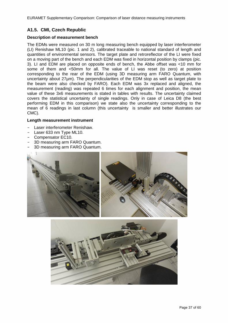
EURAMET Supplementary Comparison Comparison of laser distance measuring instruments
Page 37 of 60
A15 CMI Czech Republic
Description of measurement bench
The EDMs were measured on 30 m long measuring bench equipped by laser interferometer (LI) Renishaw ML10 (pic 1 and 2) calibrated traceable to national standard of length and quantities of environmental sensors The target plate and retroreflector of the LI were fixed on a moving part of the bench and each EDM was fixed in horizontal position by clamps (pic 3) LI and EDM are placed on opposite ends of bench the Abbe offset was lt10 mm for some of them and lt50mm for all The value of LI was reset (to zero) at position corresponding to the rear of the EDM (using 3D measuring arm FARO Quantum with uncertainty about 27microm) The perpendicularities of the EDM stop as well as target plate to the beam were also checked by FARO) Each EDM was 3x replaced and aligned the measurement (reading) was repeated 6 times for each alignment and position the mean value of these 3x6 measurements is stated in tables with results The uncertainty claimed covers the statistical uncertainty of single readings Only in case of Leica D8 (the best performing EDM in this comparison) we state also the uncertainty corresponding to the mean of 6 readings in last column (this uncertainty is smaller and better illustrates our CMC)
Length measurement instrument
- Laser interferometer Renishaw - Laser 633 nm Type ML10 - Compensator EC10 - 3D measuring arm FARO Quantum - 3D measuring arm FARO Quantum
EURAMET Supplementary Comparison Comparison of laser distance measuring instruments
Page 38 of 60
A16 SMU Slovakia
Short description of measurement bench
No bench is available at the SMU the measurements are being carried out in the underground corridor of the laboratory building with length of 428 m
The 50 m steel measuring tape KINEX was used as the reference laid on the floor and pulled by the force 50 N (the same force as had been applied during its calibration at the SMU) The calibration of reference tape was done at the SMU using ULM3m Zeiss with laser interferometer Agilent 5529 B (ie per 3 m parts)
Three mercury thermometers with the resolution of 01 degC were used along the measurement path each of them laid onto the tape and located at 667 m 1990 m (instead of 20 m because of this was one of measuring points) and 333 m respectively Each of them thus corresponded approximately to one third of the measured steel tape section
Regarding the 03 m measuring point the ULM3m Zeiss length measuring machine was used with the 300 mm gauge block as the reference
Length measurement instrument
We used our own target plate being fixed perpendicularly (within uncertainty stated) to the construction equipped with nonius and the camera holder transported manually along the steel tape The second construction was fixed to the tape by such a way that zero line of the tape corresponded to the rear of EDM (within uncertainty stated)
The position of the target is read on the monitor and 20 repeated readings of the EDM data took place in each measuring point (multiples of 5 m up to 40 m)
Concerning 03 m the 300 mm gauge block was fit between the target plate and the construction with EDM The distance of the EDM rear from the target plate corresponded to the length of gauge block (within uncertainty stated)
Additional remarks
The identical measurement method was used as we use to do within our calibration service although the results reporting is different ndash we provide the regression line calculated from the measurement of irregularly distributed points and corresponding uncertainty (k = 2) in the form of [a bL] mm (ie the same coefficients for each length in the range (0 ndash 42) m)
SMU hasnrsquot got this category in CMC tables
EURAMET Supplementary Comparison Comparison of laser distance measuring instruments
Page 39 of 60
A17 INM Romania
Short description of measurement bench
Geodesic base located in the basement of the laboratory with nominal length equal to 50 m having a mobile carriage thet support both laser He-Ne retroreflector and the target of the laser distance measuring instrument in the front of geodesic base exists a support where are aligned both laser interferometer and the laser distance measuring instruments
Length measurement instrument
Laser interferometer type Hewlett Packard model 5526 A with nominal length equal to 50 m resolution 0001 mm
U = 02 microm +0510-6L
Additional remarks
During the measurements the maximum gradient of temperature was equal to 05 degC
EURAMET Supplementary Comparison Comparison of laser distance measuring instruments
Page 40 of 60
A18 INRIM Italy
Short description of measurement bench
The facility for long distance measurements is located in a corridor of the gallery devoted to dimensional metrology The structure consists in a 28 m long rail fixed to a series of pillars which rest directly on the ground released from the vibrations of floor and wall The measuring system is based on a heterodyne interferometer whose mobile arm consists of a hollow retro-reflector mounted on a structure that can run along the rail so-called carriage A photograph of the facility is presented in Fig1
The carriage is moved by a micro-step motor the motor driver receives a digital pulse and converts it into an electrical pulse to run the motor Each pulse causes a rotation of the motor shaft of one step which amounts to 11000 of a complete revolution of the shaft If the pulse frequency increases the rotation becomes continuous with a speed that is directly proportional to the pulse frequency The speed ranges between few microms up to 27 ms with a resolution of 03 microms
Since the carriage must move back and forth automatically for a distance of almost 30 m a remote control to send pulses to the motor driver was implemented It consists of two parts a radio command which allows to set some general parameters of the carriage movement such as the movement direction and mode of travel (slow or fast) and a fast command which is performed by an amplitude modulated laser beam placed at the beginning of the track oriented towards the carriage A photo detector placed above the carriage receives the modulated laser beam which is transformed into pulses to be sent to the driver of the motor The modulation of the laser beam is implemented by a LabView program that controls a digital output of the data acquisition device
Length measurement instrument
The length measurement instrument is based on a heterodyne incremental interferometer The main beam of the interferometer with frequency f1 is generated by a frequency stabilized
EURAMET Supplementary Comparison Comparison of laser distance measuring instruments
Page 41 of 60
He-Ne laser calibrated with respect to the INRIM length standard and sent to the measurement arm the second beam is a portion of the first one diffracted by an acousto-optic modulator (AOM) with frequency f2 = f1 + 80 MHz The reference detector acquires the beat note signal at 80 MHz while the measurement detector acquires a signal at 80 MHz whose phase is varied due to the displacement of the retro-reflector moving on the rail In figure 2 the optical design of the interferometer is presented
Two different measuring techniques have been implemented
1 the ldquophase measuringrdquo technique based on fringes counting with a relative uncertainty of 5middot10-7 but limited at the maximum carriage speed of 3 cms
2 the ldquoDoppler frequency measurementrdquo technique for higher carriage speed based on the measurement of the Doppler frequency shift while the carriage runs
The second technique was validated by means of the comparison with the first technique at low speed with an agreement of the order of 3middot10-6 hence the Doppler frequency method could be considered validated within 01 mm over the whole rail path with the advantage of reducing the time needed to cover long distances so it was used for the EDM comparison
In order to obtain the distance covered by the carriage according to technique 2 the Doppler frequency is measured by a commercial high-performance counter (a Pendulum CNT-90) without dead time based on time stamping then it is converted in speed and integrated over time according to the following formula
( ) ( )int minus=minus= tffn
dtn
ffdairair
λλ
2
1
2
1
where d is the distance covered by the carriage f is the frequency of the measuring signal with the carriage at rest frsquo the frequency of the measuring signal with the carriage moving λi
is the wavelength of the laser in vacuum n - air is the air refractive index and ti is the integration time The difference frsquo-f is just the Doppler frequency due to the moving carriage
The time interval measurement resolution of the instrument is 100 ps and the time base is
EURAMET Supplementary Comparison Comparison of laser distance measuring instruments
Page 42 of 60
connected to the INRIM UTC so that the measurements of the Doppler frequency and the integration time are extremely accurate The environmental parameters such as air temperature atmospheric pressure partial pressure of water were monitored during the measurement process in order to calculate the value of air refractive index according to the Edlenrsquos formula
Comparison set-up
The different technical solutions adopted for the EDMs and for the target plate positioning are discussed in this paragraph and sketched in figure 3
Fig 3 picture of the EDM and target positioning area
Target plate positioning
In order to use the provided target plate an ad-hoc mounting was manufactured at INRIM it consists in a sort of picture frame made in aluminum which slightly clamps the target folded in half and gives it the necessary stiffness to be a reproducible target The upper part of the frame is L-shaped and allows it to be fixed to the carriage structure by means of two screws The rear part of the target mounting is depicted in figure 4 The target mounting was considered necessary because of the poor stiffness and planarity of the plastic target With the aluminium frame a planarity better than 01 mm was guaranteed The target plate is placed few centimetres next to the retro-reflector and normal to the interferometer beam axis since the EDM laser should be as close and parallel as possible to the reference beam
EURAMET Supplementary Comparison Comparison of laser distance measuring instruments
Page 43 of 60
Fig 4 picture of the rear part of the target plate mounting
EDMsrsquo positioning
The EDMs are placed on a cradle-like platform which is able to adjust the inclination of the EDM along the longitudinal axis (pitch angle) The platform height allows the EDMs to be at approx the same height as the interferometer beam A crucial role was played by the stop-wall placed behind the platform since it represents the ldquozero pointrdquo for all the length measurement Hence a particular effort was devoted to align the stop-wall so that it was normal to the interferometer beam axis and parallel to the target plate
Fig 5 detail of EDMsrsquo positioning the cradle-like platform and the stop-wall are well visible
EURAMET Supplementary Comparison Comparison of laser distance measuring instruments
Page 44 of 60
Target and stop-wall alignment
In order to have the stop-wall parallel to the target plate and normal to the interferometer beam axis the following procedure has been used
1) the stop-wall and the target plate were roughly placed trying to set them parallel and normal to the rail by eye (ie within few millimeters)
2) in order to check if the target was normal to the rail one EDM was positioned on the platform the pitch and yaw angles of the EDM were adjusted by observing the position of the EDM laser spot on the target plate when the target is moved along the rail fixed position means laser beam parallel to the carriage movement Then the target was moved until the end of the rail and a thin mirror was kept in contact with it hence observing the EDM laser reflected by the mirror it was possible to adjust the target tilt acting on the screws until the laser beam is reflected back to the source
3) finally in order to check the parallelism between the stop-wall and the target a tool made by a laser pointing orthogonally to its base was used the base was leant against the stop-wall and the laser was centered on the target when the target is near then the target was moved until the end of the rail hence observing the spot of the laser on the target it was possible to adjust the stop-wall orientation
The residual misalignment errors which we were not able to eliminate were kept into account in the uncertainty budget
Measurement of the first 30 cm
Due to the geometry of our set-up it was not possible to perform the first point of measurement by means of the interferometer indeed the carriage (hence the target) is not able to go in contact with the stop-wall
Fig 6 measurement of the first 30 cm the ruler touching the stop-wall and the target and the mechanical probe (in the back) touching the carriage are visible
EURAMET Supplementary Comparison Comparison of laser distance measuring instruments
Page 45 of 60
So a ruler made of aluminum with rounded ends and nominal length equal to 30 cm was adopted to set the distance between the target plate and the stop-wall for the first point of measurement as it is shown in figure 6 The ruler whose length was measured by a CMM machine was inserted between the target and the stop-wall leaning against the latter and the carriage was carefully moved towards the stop-wall until the target lightly touched the ruler A mechanical probe that touches the carriage structure when carriage is in the ldquo30 cmrdquo position was used as a reference measurement to check the repeatability of this distance after each measurement set
Fig 7 detail of the mechanical probe touching the carriage
Environmental parameters
The environmental parameters such as air temperature atmospheric pressure and humidity were monitored during the whole measurement process in order to calculate the value of air refractive index according to the Edlenrsquos formula
Among these parameters the temperature distribution along the mobile arm of the interferometer was our main concern mainly for two reasons
1 the temperature control of the gallery was not perfectly working during the measurement period so temperature drifts had to be monitored
2 longitudinal temperature gradients due to non uniform heating and to the presence of electronic instruments were pretty high
To the purpose 14 thermometers were uniformly dislocated along the rail and automatically recorded for all the measurement period Both temporal drifts and gradients along the path have been taken in account in the uncertainty budget In any case maximum temperature differences along the rail are within 1 degC In fig 8 an extract from the acquisition file is shown
Unfortunately the air conditioning system did not work well during the measurement campaign hence the measurements were performed at a mean temperature of 209 degC
EURAMET Supplementary Comparison Comparison of laser distance measuring instruments
Page 46 of 60
Fig 8 each curve represents the temperature distribution along the rail during the measurements campaign
Carriage waving
Since the rail is not perfectly straight and the measurement laser is not coincident with the measurement beam the Abbegrave error due to waving of the target must be considered A quantitative measurement and a qualitative measurement were carried out With an electronic level placed on the carriage the straightness on the vertical plane has been mapped with a half meter resolution (the data are reported in fig 9) With a laser placed on the carriage the horizontal and vertical waving are qualitatively compared by looking at the movements of the light spot on a target fixed to the rail end As a conclusion the horizontal and vertical waving are comparable in magnitude and the peak to peak error is of the order of 300 arcseconds
Fig 9 vertical waving of the target measured by an electronic level placed on the carriage
EURAMET Supplementary Comparison Comparison of laser distance measuring instruments
Page 47 of 60
Measurement procedure
The measurements were carried out according to the following procedure
The target was set in the starting position with the procedure described above
In sequence the four EDMs are positioned on the base the horizontal and vertical tilt are adjusted and the distance measurement is recorded An additional fifth EDM (Bosh DLE 150 property of INRiM) was included in the measurement sequence Each EDM is placed on the base and gently pushed against the reference wall in such a way that the measurement laser beam starting point is the same for all EDMs Than the horizontal and vertical angles were adjusted in order to hit the central point of the target indicated with two black marks (see pictures 3 and 6) with ldquovisualrdquo alignment The measurement button is then pressed several times (typically 5) and the average reading is recorded Typical dispersion between readings is within few last digit units In case the dispersion between readings is too large the anomaly is recorded
The carriage was then moved in the next position (about 5 m) and the measurement sequence was repeated for the 5 EDMs The operation is repeated up to 25 m The 25 m measurement is than repeated again as well as all the points till the first one so that each point is measured twice each set Since the carriage movement is ldquoopen looprdquo the positioning of the carriage was not exactly in the nominal 5 m intervals For each positioning the incremental displacement is measured by the interferometer in the Doppler mode Finally the measured values were averaged in order to give a single value for each nominal position
At the end of the measurement set when the carriage is at the 30 cm position again the sum of the interferometric measurements should be very close to zero The residual value is compared with the difference between the first and the final measurements of the mechanical probe The difference must be within the uncertainty of the Doppler technique otherwise some error occurred in the measurement set that must be repeated
At the end of the session 10 complete sets of measurements recorded from the 20th to the 30th of January 2012 have been considered for this report
Additional remarks
Effect of laser pointing
During a preliminary set of measurements we noticed a strong and unexpected dependence of the measurement result on the position of the laser spot on the target Indeed since no particular instructions were given about the relative position of the laser spot on target position (except to exclude the central joint between the two halves) we decided to work relatively close to the right side of the target -closer to the interferometer beam- in order to reduce the Abbegrave error We noticed very large errors at large distances in particular of the Leica DISTO D3a (see figure 10)
EURAMET Supplementary Comparison Comparison of laser distance measuring instruments
Page 48 of 60
Fig 10 errors of each EDM In a preliminary set of measurements
We also noticed that this error was strongly dependent on the position of the spot on the target For this reason we carried out a set of measurements at the maximum length in different positions of the target from one edge to the other according to figure 11 The results are reported in table V
EDM A B C D E
Leica D3a -4 +1 0 +24 +43
+2 0 +42 +40
-1 0 +38
Leica D8 0 0 0 2 +7
0 +12 +23
table V deviations (in mm) from the length measured at point C aiming the laser spot at different positions of the target (notations as in figure 11)
We tried to find an explanation to this effect in the shape of the laser spot if the spot was
EURAMET Supplementary Comparison Comparison of laser distance measuring instruments
Page 49 of 60
particularly defocused or had high diffraction some of the energy could fall out of the target and affect the measurement result In fact the images of the spots (shown in fig 12) do not support this hypothesis Finally we decided to use the center of the (half) target for the comparison
Changing the target
In order to investigate the influence of the target on the measurements a cardboard foil (400 x 400) mm was fixed to the target mounting and a complete set of measurements was performed The results reported in figure 13 and 14 do not show any evidence of a possible dependency of the EDM measurement on the target kind
EURAMET Supplementary Comparison Comparison of laser distance measuring instruments
Page 50 of 60
Measurement at 50 m
Although we are not able to perform traceable length measurements beyond 28 m we wanted to get a sense of EDMs behaviour at longer distances So a target (represented by a rack side wall) was placed at approximately 50 m one after the other the EDMrsquos were positioned on the base and pointed towards the target The measurements were repeated then the target was replaced by the target used for the comparison and a third set of measurements were performed To our great surprise all the EDMrsquos were in good agreement (within 2 or 3 mm for each set of measurement) even those which showed errors of the order of five to ten millimeters at 25 m namely BOSCH DLE 50 and LEICA DISTO D3a Therefore each set of measurements was averaged and the deviations from the mean value are reported in figure 15
EURAMET Supplementary Comparison Comparison of laser distance measuring instruments
Page 51 of 60
Fig 15 Deviations from average value of the measurements At 50 m
EURAMET Supplementary Comparison Comparison of laser distance measuring instruments
Page 52 of 60
A19 CEM Spain
Short description of the measurement bench
To make the measurements of EDMs we have used a reference line made of adjustable supports fixed on a wall of the laboratory Each support is nominally separated five metres from the previous one so we can generate reference lengths up to fifty metres with a pitch of five metres The supports are designed to accommodate both targets and handheld EDMs Distances between supports were measured by using a total station traced to national standards The relative angles of the bases have been measured and corrected
Fig 1 - View of three consecutive supports of the 50 m baseline (left) Lab technician situating an EDM on the first support of the baseline (right)
Length measurement instrument
The baseline was calibrated by using a total station Leica TDA5005 with spherical reflector the calibration uncertainty being 02 mm for k = 2
The target is provided by the comparison The quality of the target was judged as not good due to geometrical constructive errors and the lack of rigidity and stability We measured the flatness of the target surface the distance edge-surface and the angle between them by using a 3D coordinate measuring machine The results of flatness and angle were included in the uncertainty budget and the distance EDM-target was corrected for each EDM due to each beam impinged on a different point of the target
We were not able to measure the distance 0 to 03 m because the baseline pitch is 5 meters and although we are able to measure shorter values in a different facility the target was not appropriate for our bench
EURAMET Supplementary Comparison Comparison of laser distance measuring instruments
Page 53 of 60
Fig 2 - View of an EDM on the first support of the baseline (left) A closer look showing the support adjustments and the origin plate (right)
Fig 3 - View of the comparison target on one of the supports of the baseline (left) A closer look showing the target edge against the support rigid reference (right)
Measurement method
The measurements were carried out by comparison against the known values of the calibrated baseline (metallic references on supports)
Environmental conditions were maintained within the following limits
- Temperature 20 ordmC plusmn 05 ordmC
- Humidity 45 plusmn 10
Each laser distance measuring instrument was placed at the first support of the base and aligned so that the laser beam was perpendicular to the target as indicated by the comparison protocol
For each measurement we took the average of thirty measurements It permitted us to evaluate the repeatability of the instrument
EURAMET Supplementary Comparison Comparison of laser distance measuring instruments
Page 54 of 60
A110 BEV Austria
Short description of the measurement bench
Fig 1 Carriage of tape bench View from the laser interferometer side Retroreflector mounted on the vertical plate the EDM target is mounted on the backside
Fig 2 Support for the DUT Adjustable with 2 translational and 2 rotational degrees of freedom respectively
Fig 3 Setting of the 300 mm starting position Note the rough-and-ready mounted target plate
Fig 4 Laser interferometer side of the bench The DUT is 50 m away on the other side
EURAMET Supplementary Comparison Comparison of laser distance measuring instruments
Page 55 of 60
Measurement procedure 1 The EDM is positioned with the help of a 4-axis positioning stage so that its laser beam is
coaxial with the measurement direction of the laser interferometer (in head on configuration)
2 The EDM is removed from its support The bench carriage is positioned so that the distance of the target plate from the EDM back support is 300 mm A length bar with spherical faces is used for this adjustment The laser interferometer is preset to 300 mm and the EDM is put back on its support
3 At each position 10 consecutive measurements are taken (repeatability) and the carriage is moved to the next position The carriage is manually moved under control of the laser interferometer until it is within plusmn30 microm at the correct position (Exception for the DLE 150 the target is not positioned at 10 m but at 10 m ndash 1 mm to make use of the higher resolution) The indicated (not the nominal) distance of the laser interferometer is recorded for the determination of the deviation
4 After reaching the 50 m position all points are measured in reverse order (bidirectional) Immediately after the last measurement the EDM is removed and the indication using the 300 mm length bar is checked (thus noting a possible drift of the setup)
5 Each instrument was measured 4 times according to this procedure on different days (reproducibility of bench and instrument)
Length measurement instrument
Agilent laser interferometer with long range option The bench was completed short time before performing these measurement So the characterisation was not complete and the respective measurement uncertainty of the laser interferometer is estimated rather high But anyway its contribution to the overall uncertainty can nearly be neglected
Additional remarks
The uncertainty originating from the DUT is the dominating uncertainty contribution Specifically the resolution of the two Bosch instruments (1 mm) and the repeatability are the largest contributions For the DLA 50 the pooled standard deviation of a reading at 50 m is larger than 2 mm Moreover the length dependence is not a simple function
All of the instruments show a significant deviation of the laser beam from the normal of the back (reference) face of the instrument The measured angles reach from 04deg (D3a) to 11deg (DLE 50) This leads depending on the outer dimensions of the instruments to a constant uncertainty contribution of 02 mm in our setup It must be noted that the reference faces are not well defined in most of the instruments
The reproducibility is quite different for the four instruments so only part of it originates from the setup For CMC claims we will use the standard uncertainty value of the most reproducible instrument (D3a) which amounts to 013 mm For an ideal instrument with a resolution of 01 mm and perfect repeatability we would thus have a constant expanded uncertainty of 053 mm up to 50 m
EURAMET Supplementary Comparison Comparison of laser distance measuring instruments
Page 56 of 60
A111 JV Norway
Short description of measurement bench
EDM under calibration and the reference system are aligned along a 50 m measurement bench with rails to carry the linear movement of a target plate for the EDM and a corner cube reflector for the reference system The distance between parallel axis of EDM and axis of the reference system is 130 mm Abbe error due to angle errors for the movement is smaller than 01 mm and is corrected for at each measurement point At long lengths an aperture is used approximately midway between the target plate and the EDM to avoid interfering stray light to the EDM
Alignment procedure
1) Alignment of reference system to the movement of the carriage (rails)
2) Alignment of the EDM to the movement of the carriage (rails)
3) Alignment of a plane mirror at the position of the target plate using back-reflection to the EDM output (normal incident of light on the mirror)
4) Take out the EDM and align the zero reference plate at the back of the EDM to the plane mirror
5) The mirror is replaced by the target plate and the target plate is aligned to the zero reference plate
6) Zero setting of the reference measurement system when target plate is at zero distance to the reference plate at the back of the EDM
7) Put the EDM back in position and realign it to the movement of the carriage (rails)
8) Zero setting of the EDM to the reference plate
Image 1) Image 2) Image 3) Image 4)
Image 1) Items 5) ndash 6) in alignment procedure
Fixture for HP linear interferometer is seen bottom right Part of Wyler instrument is seen to the left blue colour
Image 2) Items 7) and 8) in alignment procedure
Micrometer screws for angle alignment in two directions and linear translation for zero setting of the EDM Push button on the EDM is positioned at the tilting point of the angle adjustment table to maximize stability during measurement HP 5519 A laser head is seen to the right
Image 3) Ready to measure at selected distances from zero point the reference plate
Image 4) EDM spot size at 50 m
Length measurement instrument
- Hewlett Packard Dynamic Calibrator 5519 A (max range 80 m)
- Pressure air temperature humidity Vaisala
EURAMET Supplementary Comparison Comparison of laser distance measuring instruments
Page 57 of 60
- Digital high resolution angle measurement Wyler
I used our own target plate which is of the same type as enclosed in the artefact suitcase article number 766560 from Leica but with reduced size width x hight = 90 x 137 mm
The zero reference plate is of similar type and size
Before measurements batteries of EDMs were switched to new batteries Old batteries are switched back after calibration
For L gt 5 m an aperture of similar size as the target plate is used approximately midway between the EDM and the target plate
Additional remarks
Reports on EDM indicated values at each measurement point is the average value of n = 5 repetitions A linear model of the standard deviation for the repeatability of the EDM readings at different lengths is estimated using m = 20 repetitions at least 5 positions along the scale An estimate of the length dependent repeatability is made for each instrument
The expanded uncertainty U(95) is rounded up to the limiting resolution of 1 mm in the interval 10 m to 40 m for Bosch GLM 150
After the calibration we also estimated the angle error of the optical axis of the EDM to its back plane (back reference of EDM) Bosch DLE 50 26 mrad up measured at 50 m Bosch GLM 150 8 mrad to the left measured at 50 m Leica DISTO D3a 37 mrad down measured at 20 m Leica DISTO D8 2 mrad to the left and 4 mrad down (45 mrad total) measured at 20 m
The distance between parallel walls will be measured too large if the back plane is assumed to be normal to the optical axis of the EDM by ∆LL = (1cosα ndash 1) Bosch DLE 50 ∆LL = 340 ppm (∆L = 17 mm at L = 50 m) Bosch GLM 150 ∆LL = 32 ppm (∆L = 16 mm at L = 50 m) Leica DISTO D3a ∆LL = 7 ppm (∆L = 034 mm at L = 50 m) Leica DISTO D8 ∆LL = 10 ppm (∆L = 05 mm at L = 50 m)
EURAMET Supplementary Comparison Comparison of laser distance measuring instruments
Page 58 of 60
A112 METAS Switzerland
Short description of measurement bench (photo recom mended)
50 m bench with laser interferometer (see photo detailed description in Michel Degoumois Un Long laboratoire de mesure OFMETinfo Vol5 No 2 1998)
Length measurement instrument
HP 5529 B laser interferometer range 80 m
EURAMET Supplementary Comparison Comparison of laser distance measuring instruments
Page 59 of 60
A113 GUM Poland
Short description of measurement bench
The 50 m bench is situated in the corridor laboratory located in the basement and has its own air conditioning system with air temperature 20 plusmn 1 degC and humidity 50 plusmn 10 RH The measuring carriage is carried microscope with CCD camera and the optics associated with the interferometer The carriage is driven using belt-transmission and electrical engine with remote ndash controlled variable speed drive
The EDM was placed on the fixed adjustable plate on the other end than laser interferometer The target plate of the EDM was placed on the measuring carriage For each EDM 3 series of measurement were done Before the each measurement EDM was repositioned and aligned again
Length measurement instrument
1 Laser interferometer HP 5529A with long-range option laser head HP 5519A
2 Ambient measurement system number and location of sensors - 20 air temperature sensors type YSI with KEITHLEY multimeter they are placed very
close to axis of the laser beam - air pressure and humidity are measured with Vaisala barometer and
thermohigrometer - CO2 content was measured with analyzer made by Intelli Charge type SPN 4462
EURAMET Supplementary Comparison Comparison of laser distance measuring instruments
Page 60 of 60
Appendix 2 Corrections of reports
131 CEM Spain
CEM reported two errors in their report
1) Bosch GLM 150 EDM error for 35 m should be -08 mm instead of the indicated 08 mm
2) Leica DISTO D8 EDM error for 35 m should be -019 mm instead of the indicated 019 mm
Proposed corrections have been included in Tables 2 and 4 of the Final Report
132 AS Metrosert Estonia
AS Metrosert reported mixed up of all results for Bosch DLE 50 and Bosch GLM 150 The results and uncertainties sent for DLE 50 was results for GLM 150 and vice versa
Proposed corrections have been included in Tables 1 and 2 of the Final Report
133 INRIM Italy
Among the data reported from INRIM some anomalies were found in the measurements of BOSCH DLE 50 and LEICA DISTO D3a at distances of 20 and 25 m
After preliminary discussion on Draft A it was understood that those anomalies could be explained as a sensitivity of said instruments to the laser light that once diffused by the target is reflected by surfaces parallel to the measurement axis and detected together with the wanted signal The superimposition of the two signals can cause a ldquopullingrdquo effect leading to an overestimation of the distance being the reflected path always longer than the direct one Indeed in the INRIMrsquos set-up the target was mounted pretty close to the flat rail used for the carriage movement being likely responsible for unwanted reflections that disturbed the measurements
Since the errors reported in INRIMrsquos measurements can be ascribed to a defect of BOSCH DLE 50 and LEICA DISTO D3a andor to a lack of description of the working conditions of said instruments INRIM asked to eliminate its measurement points at 20 and 25 m of said instruments from the comparison
Proposed corrections have been included in Tables 1 and 3 of the Final Report
134 JV Norway
Justervesenet has changed the procedure and introduced two apertures instead of only one aperture (iris) which was positioned at half distance between EDM and target The reason is that the reference beam also has an aperture and it is positioned right below the beam from the EDM (130 mm distance between axes) Some diffusively reflected stray light from the EDM target might enter the aperture for the reference beam reflect at the measurement table and reach the detector of the EDM In our calibration set-up we have only seen problems at L gt 30 m We will position the first aperture at ca 5 m from the EDM and then the second aperture at ca 25 m This combination of two apertures will effectively eliminate interference of stray light from the measurement table to the EDM detector for all lengths up to 50 m
Justervesenet also increases the uncertainty component regarding repeatability reproducibility so that the expanded uncertainty increases from 14 mm to 15 mm
EURAMET Supplementary Comparison Comparison of laser distance measuring instruments
Page 38 of 60
A16 SMU Slovakia
Short description of measurement bench
No bench is available at the SMU the measurements are being carried out in the underground corridor of the laboratory building with length of 428 m
The 50 m steel measuring tape KINEX was used as the reference laid on the floor and pulled by the force 50 N (the same force as had been applied during its calibration at the SMU) The calibration of reference tape was done at the SMU using ULM3m Zeiss with laser interferometer Agilent 5529 B (ie per 3 m parts)
Three mercury thermometers with the resolution of 01 degC were used along the measurement path each of them laid onto the tape and located at 667 m 1990 m (instead of 20 m because of this was one of measuring points) and 333 m respectively Each of them thus corresponded approximately to one third of the measured steel tape section
Regarding the 03 m measuring point the ULM3m Zeiss length measuring machine was used with the 300 mm gauge block as the reference
Length measurement instrument
We used our own target plate being fixed perpendicularly (within uncertainty stated) to the construction equipped with nonius and the camera holder transported manually along the steel tape The second construction was fixed to the tape by such a way that zero line of the tape corresponded to the rear of EDM (within uncertainty stated)
The position of the target is read on the monitor and 20 repeated readings of the EDM data took place in each measuring point (multiples of 5 m up to 40 m)
Concerning 03 m the 300 mm gauge block was fit between the target plate and the construction with EDM The distance of the EDM rear from the target plate corresponded to the length of gauge block (within uncertainty stated)
Additional remarks
The identical measurement method was used as we use to do within our calibration service although the results reporting is different ndash we provide the regression line calculated from the measurement of irregularly distributed points and corresponding uncertainty (k = 2) in the form of [a bL] mm (ie the same coefficients for each length in the range (0 ndash 42) m)
SMU hasnrsquot got this category in CMC tables
EURAMET Supplementary Comparison Comparison of laser distance measuring instruments
Page 39 of 60
A17 INM Romania
Short description of measurement bench
Geodesic base located in the basement of the laboratory with nominal length equal to 50 m having a mobile carriage thet support both laser He-Ne retroreflector and the target of the laser distance measuring instrument in the front of geodesic base exists a support where are aligned both laser interferometer and the laser distance measuring instruments
Length measurement instrument
Laser interferometer type Hewlett Packard model 5526 A with nominal length equal to 50 m resolution 0001 mm
U = 02 microm +0510-6L
Additional remarks
During the measurements the maximum gradient of temperature was equal to 05 degC
EURAMET Supplementary Comparison Comparison of laser distance measuring instruments
Page 40 of 60
A18 INRIM Italy
Short description of measurement bench
The facility for long distance measurements is located in a corridor of the gallery devoted to dimensional metrology The structure consists in a 28 m long rail fixed to a series of pillars which rest directly on the ground released from the vibrations of floor and wall The measuring system is based on a heterodyne interferometer whose mobile arm consists of a hollow retro-reflector mounted on a structure that can run along the rail so-called carriage A photograph of the facility is presented in Fig1
The carriage is moved by a micro-step motor the motor driver receives a digital pulse and converts it into an electrical pulse to run the motor Each pulse causes a rotation of the motor shaft of one step which amounts to 11000 of a complete revolution of the shaft If the pulse frequency increases the rotation becomes continuous with a speed that is directly proportional to the pulse frequency The speed ranges between few microms up to 27 ms with a resolution of 03 microms
Since the carriage must move back and forth automatically for a distance of almost 30 m a remote control to send pulses to the motor driver was implemented It consists of two parts a radio command which allows to set some general parameters of the carriage movement such as the movement direction and mode of travel (slow or fast) and a fast command which is performed by an amplitude modulated laser beam placed at the beginning of the track oriented towards the carriage A photo detector placed above the carriage receives the modulated laser beam which is transformed into pulses to be sent to the driver of the motor The modulation of the laser beam is implemented by a LabView program that controls a digital output of the data acquisition device
Length measurement instrument
The length measurement instrument is based on a heterodyne incremental interferometer The main beam of the interferometer with frequency f1 is generated by a frequency stabilized
EURAMET Supplementary Comparison Comparison of laser distance measuring instruments
Page 41 of 60
He-Ne laser calibrated with respect to the INRIM length standard and sent to the measurement arm the second beam is a portion of the first one diffracted by an acousto-optic modulator (AOM) with frequency f2 = f1 + 80 MHz The reference detector acquires the beat note signal at 80 MHz while the measurement detector acquires a signal at 80 MHz whose phase is varied due to the displacement of the retro-reflector moving on the rail In figure 2 the optical design of the interferometer is presented
Two different measuring techniques have been implemented
1 the ldquophase measuringrdquo technique based on fringes counting with a relative uncertainty of 5middot10-7 but limited at the maximum carriage speed of 3 cms
2 the ldquoDoppler frequency measurementrdquo technique for higher carriage speed based on the measurement of the Doppler frequency shift while the carriage runs
The second technique was validated by means of the comparison with the first technique at low speed with an agreement of the order of 3middot10-6 hence the Doppler frequency method could be considered validated within 01 mm over the whole rail path with the advantage of reducing the time needed to cover long distances so it was used for the EDM comparison
In order to obtain the distance covered by the carriage according to technique 2 the Doppler frequency is measured by a commercial high-performance counter (a Pendulum CNT-90) without dead time based on time stamping then it is converted in speed and integrated over time according to the following formula
( ) ( )int minus=minus= tffn
dtn
ffdairair
λλ
2
1
2
1
where d is the distance covered by the carriage f is the frequency of the measuring signal with the carriage at rest frsquo the frequency of the measuring signal with the carriage moving λi
is the wavelength of the laser in vacuum n - air is the air refractive index and ti is the integration time The difference frsquo-f is just the Doppler frequency due to the moving carriage
The time interval measurement resolution of the instrument is 100 ps and the time base is
EURAMET Supplementary Comparison Comparison of laser distance measuring instruments
Page 42 of 60
connected to the INRIM UTC so that the measurements of the Doppler frequency and the integration time are extremely accurate The environmental parameters such as air temperature atmospheric pressure partial pressure of water were monitored during the measurement process in order to calculate the value of air refractive index according to the Edlenrsquos formula
Comparison set-up
The different technical solutions adopted for the EDMs and for the target plate positioning are discussed in this paragraph and sketched in figure 3
Fig 3 picture of the EDM and target positioning area
Target plate positioning
In order to use the provided target plate an ad-hoc mounting was manufactured at INRIM it consists in a sort of picture frame made in aluminum which slightly clamps the target folded in half and gives it the necessary stiffness to be a reproducible target The upper part of the frame is L-shaped and allows it to be fixed to the carriage structure by means of two screws The rear part of the target mounting is depicted in figure 4 The target mounting was considered necessary because of the poor stiffness and planarity of the plastic target With the aluminium frame a planarity better than 01 mm was guaranteed The target plate is placed few centimetres next to the retro-reflector and normal to the interferometer beam axis since the EDM laser should be as close and parallel as possible to the reference beam
EURAMET Supplementary Comparison Comparison of laser distance measuring instruments
Page 43 of 60
Fig 4 picture of the rear part of the target plate mounting
EDMsrsquo positioning
The EDMs are placed on a cradle-like platform which is able to adjust the inclination of the EDM along the longitudinal axis (pitch angle) The platform height allows the EDMs to be at approx the same height as the interferometer beam A crucial role was played by the stop-wall placed behind the platform since it represents the ldquozero pointrdquo for all the length measurement Hence a particular effort was devoted to align the stop-wall so that it was normal to the interferometer beam axis and parallel to the target plate
Fig 5 detail of EDMsrsquo positioning the cradle-like platform and the stop-wall are well visible
EURAMET Supplementary Comparison Comparison of laser distance measuring instruments
Page 44 of 60
Target and stop-wall alignment
In order to have the stop-wall parallel to the target plate and normal to the interferometer beam axis the following procedure has been used
1) the stop-wall and the target plate were roughly placed trying to set them parallel and normal to the rail by eye (ie within few millimeters)
2) in order to check if the target was normal to the rail one EDM was positioned on the platform the pitch and yaw angles of the EDM were adjusted by observing the position of the EDM laser spot on the target plate when the target is moved along the rail fixed position means laser beam parallel to the carriage movement Then the target was moved until the end of the rail and a thin mirror was kept in contact with it hence observing the EDM laser reflected by the mirror it was possible to adjust the target tilt acting on the screws until the laser beam is reflected back to the source
3) finally in order to check the parallelism between the stop-wall and the target a tool made by a laser pointing orthogonally to its base was used the base was leant against the stop-wall and the laser was centered on the target when the target is near then the target was moved until the end of the rail hence observing the spot of the laser on the target it was possible to adjust the stop-wall orientation
The residual misalignment errors which we were not able to eliminate were kept into account in the uncertainty budget
Measurement of the first 30 cm
Due to the geometry of our set-up it was not possible to perform the first point of measurement by means of the interferometer indeed the carriage (hence the target) is not able to go in contact with the stop-wall
Fig 6 measurement of the first 30 cm the ruler touching the stop-wall and the target and the mechanical probe (in the back) touching the carriage are visible
EURAMET Supplementary Comparison Comparison of laser distance measuring instruments
Page 45 of 60
So a ruler made of aluminum with rounded ends and nominal length equal to 30 cm was adopted to set the distance between the target plate and the stop-wall for the first point of measurement as it is shown in figure 6 The ruler whose length was measured by a CMM machine was inserted between the target and the stop-wall leaning against the latter and the carriage was carefully moved towards the stop-wall until the target lightly touched the ruler A mechanical probe that touches the carriage structure when carriage is in the ldquo30 cmrdquo position was used as a reference measurement to check the repeatability of this distance after each measurement set
Fig 7 detail of the mechanical probe touching the carriage
Environmental parameters
The environmental parameters such as air temperature atmospheric pressure and humidity were monitored during the whole measurement process in order to calculate the value of air refractive index according to the Edlenrsquos formula
Among these parameters the temperature distribution along the mobile arm of the interferometer was our main concern mainly for two reasons
1 the temperature control of the gallery was not perfectly working during the measurement period so temperature drifts had to be monitored
2 longitudinal temperature gradients due to non uniform heating and to the presence of electronic instruments were pretty high
To the purpose 14 thermometers were uniformly dislocated along the rail and automatically recorded for all the measurement period Both temporal drifts and gradients along the path have been taken in account in the uncertainty budget In any case maximum temperature differences along the rail are within 1 degC In fig 8 an extract from the acquisition file is shown
Unfortunately the air conditioning system did not work well during the measurement campaign hence the measurements were performed at a mean temperature of 209 degC
EURAMET Supplementary Comparison Comparison of laser distance measuring instruments
Page 46 of 60
Fig 8 each curve represents the temperature distribution along the rail during the measurements campaign
Carriage waving
Since the rail is not perfectly straight and the measurement laser is not coincident with the measurement beam the Abbegrave error due to waving of the target must be considered A quantitative measurement and a qualitative measurement were carried out With an electronic level placed on the carriage the straightness on the vertical plane has been mapped with a half meter resolution (the data are reported in fig 9) With a laser placed on the carriage the horizontal and vertical waving are qualitatively compared by looking at the movements of the light spot on a target fixed to the rail end As a conclusion the horizontal and vertical waving are comparable in magnitude and the peak to peak error is of the order of 300 arcseconds
Fig 9 vertical waving of the target measured by an electronic level placed on the carriage
EURAMET Supplementary Comparison Comparison of laser distance measuring instruments
Page 47 of 60
Measurement procedure
The measurements were carried out according to the following procedure
The target was set in the starting position with the procedure described above
In sequence the four EDMs are positioned on the base the horizontal and vertical tilt are adjusted and the distance measurement is recorded An additional fifth EDM (Bosh DLE 150 property of INRiM) was included in the measurement sequence Each EDM is placed on the base and gently pushed against the reference wall in such a way that the measurement laser beam starting point is the same for all EDMs Than the horizontal and vertical angles were adjusted in order to hit the central point of the target indicated with two black marks (see pictures 3 and 6) with ldquovisualrdquo alignment The measurement button is then pressed several times (typically 5) and the average reading is recorded Typical dispersion between readings is within few last digit units In case the dispersion between readings is too large the anomaly is recorded
The carriage was then moved in the next position (about 5 m) and the measurement sequence was repeated for the 5 EDMs The operation is repeated up to 25 m The 25 m measurement is than repeated again as well as all the points till the first one so that each point is measured twice each set Since the carriage movement is ldquoopen looprdquo the positioning of the carriage was not exactly in the nominal 5 m intervals For each positioning the incremental displacement is measured by the interferometer in the Doppler mode Finally the measured values were averaged in order to give a single value for each nominal position
At the end of the measurement set when the carriage is at the 30 cm position again the sum of the interferometric measurements should be very close to zero The residual value is compared with the difference between the first and the final measurements of the mechanical probe The difference must be within the uncertainty of the Doppler technique otherwise some error occurred in the measurement set that must be repeated
At the end of the session 10 complete sets of measurements recorded from the 20th to the 30th of January 2012 have been considered for this report
Additional remarks
Effect of laser pointing
During a preliminary set of measurements we noticed a strong and unexpected dependence of the measurement result on the position of the laser spot on the target Indeed since no particular instructions were given about the relative position of the laser spot on target position (except to exclude the central joint between the two halves) we decided to work relatively close to the right side of the target -closer to the interferometer beam- in order to reduce the Abbegrave error We noticed very large errors at large distances in particular of the Leica DISTO D3a (see figure 10)
EURAMET Supplementary Comparison Comparison of laser distance measuring instruments
Page 48 of 60
Fig 10 errors of each EDM In a preliminary set of measurements
We also noticed that this error was strongly dependent on the position of the spot on the target For this reason we carried out a set of measurements at the maximum length in different positions of the target from one edge to the other according to figure 11 The results are reported in table V
EDM A B C D E
Leica D3a -4 +1 0 +24 +43
+2 0 +42 +40
-1 0 +38
Leica D8 0 0 0 2 +7
0 +12 +23
table V deviations (in mm) from the length measured at point C aiming the laser spot at different positions of the target (notations as in figure 11)
We tried to find an explanation to this effect in the shape of the laser spot if the spot was
EURAMET Supplementary Comparison Comparison of laser distance measuring instruments
Page 49 of 60
particularly defocused or had high diffraction some of the energy could fall out of the target and affect the measurement result In fact the images of the spots (shown in fig 12) do not support this hypothesis Finally we decided to use the center of the (half) target for the comparison
Changing the target
In order to investigate the influence of the target on the measurements a cardboard foil (400 x 400) mm was fixed to the target mounting and a complete set of measurements was performed The results reported in figure 13 and 14 do not show any evidence of a possible dependency of the EDM measurement on the target kind
EURAMET Supplementary Comparison Comparison of laser distance measuring instruments
Page 50 of 60
Measurement at 50 m
Although we are not able to perform traceable length measurements beyond 28 m we wanted to get a sense of EDMs behaviour at longer distances So a target (represented by a rack side wall) was placed at approximately 50 m one after the other the EDMrsquos were positioned on the base and pointed towards the target The measurements were repeated then the target was replaced by the target used for the comparison and a third set of measurements were performed To our great surprise all the EDMrsquos were in good agreement (within 2 or 3 mm for each set of measurement) even those which showed errors of the order of five to ten millimeters at 25 m namely BOSCH DLE 50 and LEICA DISTO D3a Therefore each set of measurements was averaged and the deviations from the mean value are reported in figure 15
EURAMET Supplementary Comparison Comparison of laser distance measuring instruments
Page 51 of 60
Fig 15 Deviations from average value of the measurements At 50 m
EURAMET Supplementary Comparison Comparison of laser distance measuring instruments
Page 52 of 60
A19 CEM Spain
Short description of the measurement bench
To make the measurements of EDMs we have used a reference line made of adjustable supports fixed on a wall of the laboratory Each support is nominally separated five metres from the previous one so we can generate reference lengths up to fifty metres with a pitch of five metres The supports are designed to accommodate both targets and handheld EDMs Distances between supports were measured by using a total station traced to national standards The relative angles of the bases have been measured and corrected
Fig 1 - View of three consecutive supports of the 50 m baseline (left) Lab technician situating an EDM on the first support of the baseline (right)
Length measurement instrument
The baseline was calibrated by using a total station Leica TDA5005 with spherical reflector the calibration uncertainty being 02 mm for k = 2
The target is provided by the comparison The quality of the target was judged as not good due to geometrical constructive errors and the lack of rigidity and stability We measured the flatness of the target surface the distance edge-surface and the angle between them by using a 3D coordinate measuring machine The results of flatness and angle were included in the uncertainty budget and the distance EDM-target was corrected for each EDM due to each beam impinged on a different point of the target
We were not able to measure the distance 0 to 03 m because the baseline pitch is 5 meters and although we are able to measure shorter values in a different facility the target was not appropriate for our bench
EURAMET Supplementary Comparison Comparison of laser distance measuring instruments
Page 53 of 60
Fig 2 - View of an EDM on the first support of the baseline (left) A closer look showing the support adjustments and the origin plate (right)
Fig 3 - View of the comparison target on one of the supports of the baseline (left) A closer look showing the target edge against the support rigid reference (right)
Measurement method
The measurements were carried out by comparison against the known values of the calibrated baseline (metallic references on supports)
Environmental conditions were maintained within the following limits
- Temperature 20 ordmC plusmn 05 ordmC
- Humidity 45 plusmn 10
Each laser distance measuring instrument was placed at the first support of the base and aligned so that the laser beam was perpendicular to the target as indicated by the comparison protocol
For each measurement we took the average of thirty measurements It permitted us to evaluate the repeatability of the instrument
EURAMET Supplementary Comparison Comparison of laser distance measuring instruments
Page 54 of 60
A110 BEV Austria
Short description of the measurement bench
Fig 1 Carriage of tape bench View from the laser interferometer side Retroreflector mounted on the vertical plate the EDM target is mounted on the backside
Fig 2 Support for the DUT Adjustable with 2 translational and 2 rotational degrees of freedom respectively
Fig 3 Setting of the 300 mm starting position Note the rough-and-ready mounted target plate
Fig 4 Laser interferometer side of the bench The DUT is 50 m away on the other side
EURAMET Supplementary Comparison Comparison of laser distance measuring instruments
Page 55 of 60
Measurement procedure 1 The EDM is positioned with the help of a 4-axis positioning stage so that its laser beam is
coaxial with the measurement direction of the laser interferometer (in head on configuration)
2 The EDM is removed from its support The bench carriage is positioned so that the distance of the target plate from the EDM back support is 300 mm A length bar with spherical faces is used for this adjustment The laser interferometer is preset to 300 mm and the EDM is put back on its support
3 At each position 10 consecutive measurements are taken (repeatability) and the carriage is moved to the next position The carriage is manually moved under control of the laser interferometer until it is within plusmn30 microm at the correct position (Exception for the DLE 150 the target is not positioned at 10 m but at 10 m ndash 1 mm to make use of the higher resolution) The indicated (not the nominal) distance of the laser interferometer is recorded for the determination of the deviation
4 After reaching the 50 m position all points are measured in reverse order (bidirectional) Immediately after the last measurement the EDM is removed and the indication using the 300 mm length bar is checked (thus noting a possible drift of the setup)
5 Each instrument was measured 4 times according to this procedure on different days (reproducibility of bench and instrument)
Length measurement instrument
Agilent laser interferometer with long range option The bench was completed short time before performing these measurement So the characterisation was not complete and the respective measurement uncertainty of the laser interferometer is estimated rather high But anyway its contribution to the overall uncertainty can nearly be neglected
Additional remarks
The uncertainty originating from the DUT is the dominating uncertainty contribution Specifically the resolution of the two Bosch instruments (1 mm) and the repeatability are the largest contributions For the DLA 50 the pooled standard deviation of a reading at 50 m is larger than 2 mm Moreover the length dependence is not a simple function
All of the instruments show a significant deviation of the laser beam from the normal of the back (reference) face of the instrument The measured angles reach from 04deg (D3a) to 11deg (DLE 50) This leads depending on the outer dimensions of the instruments to a constant uncertainty contribution of 02 mm in our setup It must be noted that the reference faces are not well defined in most of the instruments
The reproducibility is quite different for the four instruments so only part of it originates from the setup For CMC claims we will use the standard uncertainty value of the most reproducible instrument (D3a) which amounts to 013 mm For an ideal instrument with a resolution of 01 mm and perfect repeatability we would thus have a constant expanded uncertainty of 053 mm up to 50 m
EURAMET Supplementary Comparison Comparison of laser distance measuring instruments
Page 56 of 60
A111 JV Norway
Short description of measurement bench
EDM under calibration and the reference system are aligned along a 50 m measurement bench with rails to carry the linear movement of a target plate for the EDM and a corner cube reflector for the reference system The distance between parallel axis of EDM and axis of the reference system is 130 mm Abbe error due to angle errors for the movement is smaller than 01 mm and is corrected for at each measurement point At long lengths an aperture is used approximately midway between the target plate and the EDM to avoid interfering stray light to the EDM
Alignment procedure
1) Alignment of reference system to the movement of the carriage (rails)
2) Alignment of the EDM to the movement of the carriage (rails)
3) Alignment of a plane mirror at the position of the target plate using back-reflection to the EDM output (normal incident of light on the mirror)
4) Take out the EDM and align the zero reference plate at the back of the EDM to the plane mirror
5) The mirror is replaced by the target plate and the target plate is aligned to the zero reference plate
6) Zero setting of the reference measurement system when target plate is at zero distance to the reference plate at the back of the EDM
7) Put the EDM back in position and realign it to the movement of the carriage (rails)
8) Zero setting of the EDM to the reference plate
Image 1) Image 2) Image 3) Image 4)
Image 1) Items 5) ndash 6) in alignment procedure
Fixture for HP linear interferometer is seen bottom right Part of Wyler instrument is seen to the left blue colour
Image 2) Items 7) and 8) in alignment procedure
Micrometer screws for angle alignment in two directions and linear translation for zero setting of the EDM Push button on the EDM is positioned at the tilting point of the angle adjustment table to maximize stability during measurement HP 5519 A laser head is seen to the right
Image 3) Ready to measure at selected distances from zero point the reference plate
Image 4) EDM spot size at 50 m
Length measurement instrument
- Hewlett Packard Dynamic Calibrator 5519 A (max range 80 m)
- Pressure air temperature humidity Vaisala
EURAMET Supplementary Comparison Comparison of laser distance measuring instruments
Page 57 of 60
- Digital high resolution angle measurement Wyler
I used our own target plate which is of the same type as enclosed in the artefact suitcase article number 766560 from Leica but with reduced size width x hight = 90 x 137 mm
The zero reference plate is of similar type and size
Before measurements batteries of EDMs were switched to new batteries Old batteries are switched back after calibration
For L gt 5 m an aperture of similar size as the target plate is used approximately midway between the EDM and the target plate
Additional remarks
Reports on EDM indicated values at each measurement point is the average value of n = 5 repetitions A linear model of the standard deviation for the repeatability of the EDM readings at different lengths is estimated using m = 20 repetitions at least 5 positions along the scale An estimate of the length dependent repeatability is made for each instrument
The expanded uncertainty U(95) is rounded up to the limiting resolution of 1 mm in the interval 10 m to 40 m for Bosch GLM 150
After the calibration we also estimated the angle error of the optical axis of the EDM to its back plane (back reference of EDM) Bosch DLE 50 26 mrad up measured at 50 m Bosch GLM 150 8 mrad to the left measured at 50 m Leica DISTO D3a 37 mrad down measured at 20 m Leica DISTO D8 2 mrad to the left and 4 mrad down (45 mrad total) measured at 20 m
The distance between parallel walls will be measured too large if the back plane is assumed to be normal to the optical axis of the EDM by ∆LL = (1cosα ndash 1) Bosch DLE 50 ∆LL = 340 ppm (∆L = 17 mm at L = 50 m) Bosch GLM 150 ∆LL = 32 ppm (∆L = 16 mm at L = 50 m) Leica DISTO D3a ∆LL = 7 ppm (∆L = 034 mm at L = 50 m) Leica DISTO D8 ∆LL = 10 ppm (∆L = 05 mm at L = 50 m)
EURAMET Supplementary Comparison Comparison of laser distance measuring instruments
Page 58 of 60
A112 METAS Switzerland
Short description of measurement bench (photo recom mended)
50 m bench with laser interferometer (see photo detailed description in Michel Degoumois Un Long laboratoire de mesure OFMETinfo Vol5 No 2 1998)
Length measurement instrument
HP 5529 B laser interferometer range 80 m
EURAMET Supplementary Comparison Comparison of laser distance measuring instruments
Page 59 of 60
A113 GUM Poland
Short description of measurement bench
The 50 m bench is situated in the corridor laboratory located in the basement and has its own air conditioning system with air temperature 20 plusmn 1 degC and humidity 50 plusmn 10 RH The measuring carriage is carried microscope with CCD camera and the optics associated with the interferometer The carriage is driven using belt-transmission and electrical engine with remote ndash controlled variable speed drive
The EDM was placed on the fixed adjustable plate on the other end than laser interferometer The target plate of the EDM was placed on the measuring carriage For each EDM 3 series of measurement were done Before the each measurement EDM was repositioned and aligned again
Length measurement instrument
1 Laser interferometer HP 5529A with long-range option laser head HP 5519A
2 Ambient measurement system number and location of sensors - 20 air temperature sensors type YSI with KEITHLEY multimeter they are placed very
close to axis of the laser beam - air pressure and humidity are measured with Vaisala barometer and
thermohigrometer - CO2 content was measured with analyzer made by Intelli Charge type SPN 4462
EURAMET Supplementary Comparison Comparison of laser distance measuring instruments
Page 60 of 60
Appendix 2 Corrections of reports
131 CEM Spain
CEM reported two errors in their report
1) Bosch GLM 150 EDM error for 35 m should be -08 mm instead of the indicated 08 mm
2) Leica DISTO D8 EDM error for 35 m should be -019 mm instead of the indicated 019 mm
Proposed corrections have been included in Tables 2 and 4 of the Final Report
132 AS Metrosert Estonia
AS Metrosert reported mixed up of all results for Bosch DLE 50 and Bosch GLM 150 The results and uncertainties sent for DLE 50 was results for GLM 150 and vice versa
Proposed corrections have been included in Tables 1 and 2 of the Final Report
133 INRIM Italy
Among the data reported from INRIM some anomalies were found in the measurements of BOSCH DLE 50 and LEICA DISTO D3a at distances of 20 and 25 m
After preliminary discussion on Draft A it was understood that those anomalies could be explained as a sensitivity of said instruments to the laser light that once diffused by the target is reflected by surfaces parallel to the measurement axis and detected together with the wanted signal The superimposition of the two signals can cause a ldquopullingrdquo effect leading to an overestimation of the distance being the reflected path always longer than the direct one Indeed in the INRIMrsquos set-up the target was mounted pretty close to the flat rail used for the carriage movement being likely responsible for unwanted reflections that disturbed the measurements
Since the errors reported in INRIMrsquos measurements can be ascribed to a defect of BOSCH DLE 50 and LEICA DISTO D3a andor to a lack of description of the working conditions of said instruments INRIM asked to eliminate its measurement points at 20 and 25 m of said instruments from the comparison
Proposed corrections have been included in Tables 1 and 3 of the Final Report
134 JV Norway
Justervesenet has changed the procedure and introduced two apertures instead of only one aperture (iris) which was positioned at half distance between EDM and target The reason is that the reference beam also has an aperture and it is positioned right below the beam from the EDM (130 mm distance between axes) Some diffusively reflected stray light from the EDM target might enter the aperture for the reference beam reflect at the measurement table and reach the detector of the EDM In our calibration set-up we have only seen problems at L gt 30 m We will position the first aperture at ca 5 m from the EDM and then the second aperture at ca 25 m This combination of two apertures will effectively eliminate interference of stray light from the measurement table to the EDM detector for all lengths up to 50 m
Justervesenet also increases the uncertainty component regarding repeatability reproducibility so that the expanded uncertainty increases from 14 mm to 15 mm
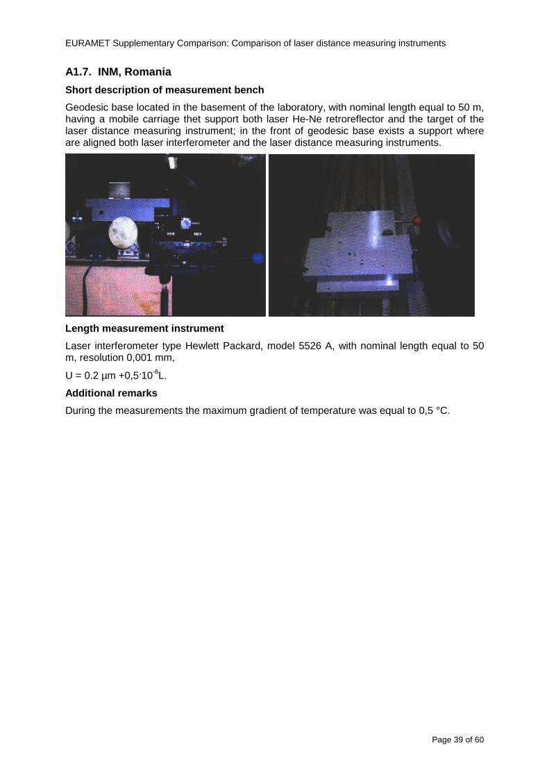
EURAMET Supplementary Comparison Comparison of laser distance measuring instruments
Page 39 of 60
A17 INM Romania
Short description of measurement bench
Geodesic base located in the basement of the laboratory with nominal length equal to 50 m having a mobile carriage thet support both laser He-Ne retroreflector and the target of the laser distance measuring instrument in the front of geodesic base exists a support where are aligned both laser interferometer and the laser distance measuring instruments
Length measurement instrument
Laser interferometer type Hewlett Packard model 5526 A with nominal length equal to 50 m resolution 0001 mm
U = 02 microm +0510-6L
Additional remarks
During the measurements the maximum gradient of temperature was equal to 05 degC
EURAMET Supplementary Comparison Comparison of laser distance measuring instruments
Page 40 of 60
A18 INRIM Italy
Short description of measurement bench
The facility for long distance measurements is located in a corridor of the gallery devoted to dimensional metrology The structure consists in a 28 m long rail fixed to a series of pillars which rest directly on the ground released from the vibrations of floor and wall The measuring system is based on a heterodyne interferometer whose mobile arm consists of a hollow retro-reflector mounted on a structure that can run along the rail so-called carriage A photograph of the facility is presented in Fig1
The carriage is moved by a micro-step motor the motor driver receives a digital pulse and converts it into an electrical pulse to run the motor Each pulse causes a rotation of the motor shaft of one step which amounts to 11000 of a complete revolution of the shaft If the pulse frequency increases the rotation becomes continuous with a speed that is directly proportional to the pulse frequency The speed ranges between few microms up to 27 ms with a resolution of 03 microms
Since the carriage must move back and forth automatically for a distance of almost 30 m a remote control to send pulses to the motor driver was implemented It consists of two parts a radio command which allows to set some general parameters of the carriage movement such as the movement direction and mode of travel (slow or fast) and a fast command which is performed by an amplitude modulated laser beam placed at the beginning of the track oriented towards the carriage A photo detector placed above the carriage receives the modulated laser beam which is transformed into pulses to be sent to the driver of the motor The modulation of the laser beam is implemented by a LabView program that controls a digital output of the data acquisition device
Length measurement instrument
The length measurement instrument is based on a heterodyne incremental interferometer The main beam of the interferometer with frequency f1 is generated by a frequency stabilized
EURAMET Supplementary Comparison Comparison of laser distance measuring instruments
Page 41 of 60
He-Ne laser calibrated with respect to the INRIM length standard and sent to the measurement arm the second beam is a portion of the first one diffracted by an acousto-optic modulator (AOM) with frequency f2 = f1 + 80 MHz The reference detector acquires the beat note signal at 80 MHz while the measurement detector acquires a signal at 80 MHz whose phase is varied due to the displacement of the retro-reflector moving on the rail In figure 2 the optical design of the interferometer is presented
Two different measuring techniques have been implemented
1 the ldquophase measuringrdquo technique based on fringes counting with a relative uncertainty of 5middot10-7 but limited at the maximum carriage speed of 3 cms
2 the ldquoDoppler frequency measurementrdquo technique for higher carriage speed based on the measurement of the Doppler frequency shift while the carriage runs
The second technique was validated by means of the comparison with the first technique at low speed with an agreement of the order of 3middot10-6 hence the Doppler frequency method could be considered validated within 01 mm over the whole rail path with the advantage of reducing the time needed to cover long distances so it was used for the EDM comparison
In order to obtain the distance covered by the carriage according to technique 2 the Doppler frequency is measured by a commercial high-performance counter (a Pendulum CNT-90) without dead time based on time stamping then it is converted in speed and integrated over time according to the following formula
( ) ( )int minus=minus= tffn
dtn
ffdairair
λλ
2
1
2
1
where d is the distance covered by the carriage f is the frequency of the measuring signal with the carriage at rest frsquo the frequency of the measuring signal with the carriage moving λi
is the wavelength of the laser in vacuum n - air is the air refractive index and ti is the integration time The difference frsquo-f is just the Doppler frequency due to the moving carriage
The time interval measurement resolution of the instrument is 100 ps and the time base is
EURAMET Supplementary Comparison Comparison of laser distance measuring instruments
Page 42 of 60
connected to the INRIM UTC so that the measurements of the Doppler frequency and the integration time are extremely accurate The environmental parameters such as air temperature atmospheric pressure partial pressure of water were monitored during the measurement process in order to calculate the value of air refractive index according to the Edlenrsquos formula
Comparison set-up
The different technical solutions adopted for the EDMs and for the target plate positioning are discussed in this paragraph and sketched in figure 3
Fig 3 picture of the EDM and target positioning area
Target plate positioning
In order to use the provided target plate an ad-hoc mounting was manufactured at INRIM it consists in a sort of picture frame made in aluminum which slightly clamps the target folded in half and gives it the necessary stiffness to be a reproducible target The upper part of the frame is L-shaped and allows it to be fixed to the carriage structure by means of two screws The rear part of the target mounting is depicted in figure 4 The target mounting was considered necessary because of the poor stiffness and planarity of the plastic target With the aluminium frame a planarity better than 01 mm was guaranteed The target plate is placed few centimetres next to the retro-reflector and normal to the interferometer beam axis since the EDM laser should be as close and parallel as possible to the reference beam
EURAMET Supplementary Comparison Comparison of laser distance measuring instruments
Page 43 of 60
Fig 4 picture of the rear part of the target plate mounting
EDMsrsquo positioning
The EDMs are placed on a cradle-like platform which is able to adjust the inclination of the EDM along the longitudinal axis (pitch angle) The platform height allows the EDMs to be at approx the same height as the interferometer beam A crucial role was played by the stop-wall placed behind the platform since it represents the ldquozero pointrdquo for all the length measurement Hence a particular effort was devoted to align the stop-wall so that it was normal to the interferometer beam axis and parallel to the target plate
Fig 5 detail of EDMsrsquo positioning the cradle-like platform and the stop-wall are well visible
EURAMET Supplementary Comparison Comparison of laser distance measuring instruments
Page 44 of 60
Target and stop-wall alignment
In order to have the stop-wall parallel to the target plate and normal to the interferometer beam axis the following procedure has been used
1) the stop-wall and the target plate were roughly placed trying to set them parallel and normal to the rail by eye (ie within few millimeters)
2) in order to check if the target was normal to the rail one EDM was positioned on the platform the pitch and yaw angles of the EDM were adjusted by observing the position of the EDM laser spot on the target plate when the target is moved along the rail fixed position means laser beam parallel to the carriage movement Then the target was moved until the end of the rail and a thin mirror was kept in contact with it hence observing the EDM laser reflected by the mirror it was possible to adjust the target tilt acting on the screws until the laser beam is reflected back to the source
3) finally in order to check the parallelism between the stop-wall and the target a tool made by a laser pointing orthogonally to its base was used the base was leant against the stop-wall and the laser was centered on the target when the target is near then the target was moved until the end of the rail hence observing the spot of the laser on the target it was possible to adjust the stop-wall orientation
The residual misalignment errors which we were not able to eliminate were kept into account in the uncertainty budget
Measurement of the first 30 cm
Due to the geometry of our set-up it was not possible to perform the first point of measurement by means of the interferometer indeed the carriage (hence the target) is not able to go in contact with the stop-wall
Fig 6 measurement of the first 30 cm the ruler touching the stop-wall and the target and the mechanical probe (in the back) touching the carriage are visible
EURAMET Supplementary Comparison Comparison of laser distance measuring instruments
Page 45 of 60
So a ruler made of aluminum with rounded ends and nominal length equal to 30 cm was adopted to set the distance between the target plate and the stop-wall for the first point of measurement as it is shown in figure 6 The ruler whose length was measured by a CMM machine was inserted between the target and the stop-wall leaning against the latter and the carriage was carefully moved towards the stop-wall until the target lightly touched the ruler A mechanical probe that touches the carriage structure when carriage is in the ldquo30 cmrdquo position was used as a reference measurement to check the repeatability of this distance after each measurement set
Fig 7 detail of the mechanical probe touching the carriage
Environmental parameters
The environmental parameters such as air temperature atmospheric pressure and humidity were monitored during the whole measurement process in order to calculate the value of air refractive index according to the Edlenrsquos formula
Among these parameters the temperature distribution along the mobile arm of the interferometer was our main concern mainly for two reasons
1 the temperature control of the gallery was not perfectly working during the measurement period so temperature drifts had to be monitored
2 longitudinal temperature gradients due to non uniform heating and to the presence of electronic instruments were pretty high
To the purpose 14 thermometers were uniformly dislocated along the rail and automatically recorded for all the measurement period Both temporal drifts and gradients along the path have been taken in account in the uncertainty budget In any case maximum temperature differences along the rail are within 1 degC In fig 8 an extract from the acquisition file is shown
Unfortunately the air conditioning system did not work well during the measurement campaign hence the measurements were performed at a mean temperature of 209 degC
EURAMET Supplementary Comparison Comparison of laser distance measuring instruments
Page 46 of 60
Fig 8 each curve represents the temperature distribution along the rail during the measurements campaign
Carriage waving
Since the rail is not perfectly straight and the measurement laser is not coincident with the measurement beam the Abbegrave error due to waving of the target must be considered A quantitative measurement and a qualitative measurement were carried out With an electronic level placed on the carriage the straightness on the vertical plane has been mapped with a half meter resolution (the data are reported in fig 9) With a laser placed on the carriage the horizontal and vertical waving are qualitatively compared by looking at the movements of the light spot on a target fixed to the rail end As a conclusion the horizontal and vertical waving are comparable in magnitude and the peak to peak error is of the order of 300 arcseconds
Fig 9 vertical waving of the target measured by an electronic level placed on the carriage
EURAMET Supplementary Comparison Comparison of laser distance measuring instruments
Page 47 of 60
Measurement procedure
The measurements were carried out according to the following procedure
The target was set in the starting position with the procedure described above
In sequence the four EDMs are positioned on the base the horizontal and vertical tilt are adjusted and the distance measurement is recorded An additional fifth EDM (Bosh DLE 150 property of INRiM) was included in the measurement sequence Each EDM is placed on the base and gently pushed against the reference wall in such a way that the measurement laser beam starting point is the same for all EDMs Than the horizontal and vertical angles were adjusted in order to hit the central point of the target indicated with two black marks (see pictures 3 and 6) with ldquovisualrdquo alignment The measurement button is then pressed several times (typically 5) and the average reading is recorded Typical dispersion between readings is within few last digit units In case the dispersion between readings is too large the anomaly is recorded
The carriage was then moved in the next position (about 5 m) and the measurement sequence was repeated for the 5 EDMs The operation is repeated up to 25 m The 25 m measurement is than repeated again as well as all the points till the first one so that each point is measured twice each set Since the carriage movement is ldquoopen looprdquo the positioning of the carriage was not exactly in the nominal 5 m intervals For each positioning the incremental displacement is measured by the interferometer in the Doppler mode Finally the measured values were averaged in order to give a single value for each nominal position
At the end of the measurement set when the carriage is at the 30 cm position again the sum of the interferometric measurements should be very close to zero The residual value is compared with the difference between the first and the final measurements of the mechanical probe The difference must be within the uncertainty of the Doppler technique otherwise some error occurred in the measurement set that must be repeated
At the end of the session 10 complete sets of measurements recorded from the 20th to the 30th of January 2012 have been considered for this report
Additional remarks
Effect of laser pointing
During a preliminary set of measurements we noticed a strong and unexpected dependence of the measurement result on the position of the laser spot on the target Indeed since no particular instructions were given about the relative position of the laser spot on target position (except to exclude the central joint between the two halves) we decided to work relatively close to the right side of the target -closer to the interferometer beam- in order to reduce the Abbegrave error We noticed very large errors at large distances in particular of the Leica DISTO D3a (see figure 10)
EURAMET Supplementary Comparison Comparison of laser distance measuring instruments
Page 48 of 60
Fig 10 errors of each EDM In a preliminary set of measurements
We also noticed that this error was strongly dependent on the position of the spot on the target For this reason we carried out a set of measurements at the maximum length in different positions of the target from one edge to the other according to figure 11 The results are reported in table V
EDM A B C D E
Leica D3a -4 +1 0 +24 +43
+2 0 +42 +40
-1 0 +38
Leica D8 0 0 0 2 +7
0 +12 +23
table V deviations (in mm) from the length measured at point C aiming the laser spot at different positions of the target (notations as in figure 11)
We tried to find an explanation to this effect in the shape of the laser spot if the spot was
EURAMET Supplementary Comparison Comparison of laser distance measuring instruments
Page 49 of 60
particularly defocused or had high diffraction some of the energy could fall out of the target and affect the measurement result In fact the images of the spots (shown in fig 12) do not support this hypothesis Finally we decided to use the center of the (half) target for the comparison
Changing the target
In order to investigate the influence of the target on the measurements a cardboard foil (400 x 400) mm was fixed to the target mounting and a complete set of measurements was performed The results reported in figure 13 and 14 do not show any evidence of a possible dependency of the EDM measurement on the target kind
EURAMET Supplementary Comparison Comparison of laser distance measuring instruments
Page 50 of 60
Measurement at 50 m
Although we are not able to perform traceable length measurements beyond 28 m we wanted to get a sense of EDMs behaviour at longer distances So a target (represented by a rack side wall) was placed at approximately 50 m one after the other the EDMrsquos were positioned on the base and pointed towards the target The measurements were repeated then the target was replaced by the target used for the comparison and a third set of measurements were performed To our great surprise all the EDMrsquos were in good agreement (within 2 or 3 mm for each set of measurement) even those which showed errors of the order of five to ten millimeters at 25 m namely BOSCH DLE 50 and LEICA DISTO D3a Therefore each set of measurements was averaged and the deviations from the mean value are reported in figure 15
EURAMET Supplementary Comparison Comparison of laser distance measuring instruments
Page 51 of 60
Fig 15 Deviations from average value of the measurements At 50 m
EURAMET Supplementary Comparison Comparison of laser distance measuring instruments
Page 52 of 60
A19 CEM Spain
Short description of the measurement bench
To make the measurements of EDMs we have used a reference line made of adjustable supports fixed on a wall of the laboratory Each support is nominally separated five metres from the previous one so we can generate reference lengths up to fifty metres with a pitch of five metres The supports are designed to accommodate both targets and handheld EDMs Distances between supports were measured by using a total station traced to national standards The relative angles of the bases have been measured and corrected
Fig 1 - View of three consecutive supports of the 50 m baseline (left) Lab technician situating an EDM on the first support of the baseline (right)
Length measurement instrument
The baseline was calibrated by using a total station Leica TDA5005 with spherical reflector the calibration uncertainty being 02 mm for k = 2
The target is provided by the comparison The quality of the target was judged as not good due to geometrical constructive errors and the lack of rigidity and stability We measured the flatness of the target surface the distance edge-surface and the angle between them by using a 3D coordinate measuring machine The results of flatness and angle were included in the uncertainty budget and the distance EDM-target was corrected for each EDM due to each beam impinged on a different point of the target
We were not able to measure the distance 0 to 03 m because the baseline pitch is 5 meters and although we are able to measure shorter values in a different facility the target was not appropriate for our bench
EURAMET Supplementary Comparison Comparison of laser distance measuring instruments
Page 53 of 60
Fig 2 - View of an EDM on the first support of the baseline (left) A closer look showing the support adjustments and the origin plate (right)
Fig 3 - View of the comparison target on one of the supports of the baseline (left) A closer look showing the target edge against the support rigid reference (right)
Measurement method
The measurements were carried out by comparison against the known values of the calibrated baseline (metallic references on supports)
Environmental conditions were maintained within the following limits
- Temperature 20 ordmC plusmn 05 ordmC
- Humidity 45 plusmn 10
Each laser distance measuring instrument was placed at the first support of the base and aligned so that the laser beam was perpendicular to the target as indicated by the comparison protocol
For each measurement we took the average of thirty measurements It permitted us to evaluate the repeatability of the instrument
EURAMET Supplementary Comparison Comparison of laser distance measuring instruments
Page 54 of 60
A110 BEV Austria
Short description of the measurement bench
Fig 1 Carriage of tape bench View from the laser interferometer side Retroreflector mounted on the vertical plate the EDM target is mounted on the backside
Fig 2 Support for the DUT Adjustable with 2 translational and 2 rotational degrees of freedom respectively
Fig 3 Setting of the 300 mm starting position Note the rough-and-ready mounted target plate
Fig 4 Laser interferometer side of the bench The DUT is 50 m away on the other side
EURAMET Supplementary Comparison Comparison of laser distance measuring instruments
Page 55 of 60
Measurement procedure 1 The EDM is positioned with the help of a 4-axis positioning stage so that its laser beam is
coaxial with the measurement direction of the laser interferometer (in head on configuration)
2 The EDM is removed from its support The bench carriage is positioned so that the distance of the target plate from the EDM back support is 300 mm A length bar with spherical faces is used for this adjustment The laser interferometer is preset to 300 mm and the EDM is put back on its support
3 At each position 10 consecutive measurements are taken (repeatability) and the carriage is moved to the next position The carriage is manually moved under control of the laser interferometer until it is within plusmn30 microm at the correct position (Exception for the DLE 150 the target is not positioned at 10 m but at 10 m ndash 1 mm to make use of the higher resolution) The indicated (not the nominal) distance of the laser interferometer is recorded for the determination of the deviation
4 After reaching the 50 m position all points are measured in reverse order (bidirectional) Immediately after the last measurement the EDM is removed and the indication using the 300 mm length bar is checked (thus noting a possible drift of the setup)
5 Each instrument was measured 4 times according to this procedure on different days (reproducibility of bench and instrument)
Length measurement instrument
Agilent laser interferometer with long range option The bench was completed short time before performing these measurement So the characterisation was not complete and the respective measurement uncertainty of the laser interferometer is estimated rather high But anyway its contribution to the overall uncertainty can nearly be neglected
Additional remarks
The uncertainty originating from the DUT is the dominating uncertainty contribution Specifically the resolution of the two Bosch instruments (1 mm) and the repeatability are the largest contributions For the DLA 50 the pooled standard deviation of a reading at 50 m is larger than 2 mm Moreover the length dependence is not a simple function
All of the instruments show a significant deviation of the laser beam from the normal of the back (reference) face of the instrument The measured angles reach from 04deg (D3a) to 11deg (DLE 50) This leads depending on the outer dimensions of the instruments to a constant uncertainty contribution of 02 mm in our setup It must be noted that the reference faces are not well defined in most of the instruments
The reproducibility is quite different for the four instruments so only part of it originates from the setup For CMC claims we will use the standard uncertainty value of the most reproducible instrument (D3a) which amounts to 013 mm For an ideal instrument with a resolution of 01 mm and perfect repeatability we would thus have a constant expanded uncertainty of 053 mm up to 50 m
EURAMET Supplementary Comparison Comparison of laser distance measuring instruments
Page 56 of 60
A111 JV Norway
Short description of measurement bench
EDM under calibration and the reference system are aligned along a 50 m measurement bench with rails to carry the linear movement of a target plate for the EDM and a corner cube reflector for the reference system The distance between parallel axis of EDM and axis of the reference system is 130 mm Abbe error due to angle errors for the movement is smaller than 01 mm and is corrected for at each measurement point At long lengths an aperture is used approximately midway between the target plate and the EDM to avoid interfering stray light to the EDM
Alignment procedure
1) Alignment of reference system to the movement of the carriage (rails)
2) Alignment of the EDM to the movement of the carriage (rails)
3) Alignment of a plane mirror at the position of the target plate using back-reflection to the EDM output (normal incident of light on the mirror)
4) Take out the EDM and align the zero reference plate at the back of the EDM to the plane mirror
5) The mirror is replaced by the target plate and the target plate is aligned to the zero reference plate
6) Zero setting of the reference measurement system when target plate is at zero distance to the reference plate at the back of the EDM
7) Put the EDM back in position and realign it to the movement of the carriage (rails)
8) Zero setting of the EDM to the reference plate
Image 1) Image 2) Image 3) Image 4)
Image 1) Items 5) ndash 6) in alignment procedure
Fixture for HP linear interferometer is seen bottom right Part of Wyler instrument is seen to the left blue colour
Image 2) Items 7) and 8) in alignment procedure
Micrometer screws for angle alignment in two directions and linear translation for zero setting of the EDM Push button on the EDM is positioned at the tilting point of the angle adjustment table to maximize stability during measurement HP 5519 A laser head is seen to the right
Image 3) Ready to measure at selected distances from zero point the reference plate
Image 4) EDM spot size at 50 m
Length measurement instrument
- Hewlett Packard Dynamic Calibrator 5519 A (max range 80 m)
- Pressure air temperature humidity Vaisala
EURAMET Supplementary Comparison Comparison of laser distance measuring instruments
Page 57 of 60
- Digital high resolution angle measurement Wyler
I used our own target plate which is of the same type as enclosed in the artefact suitcase article number 766560 from Leica but with reduced size width x hight = 90 x 137 mm
The zero reference plate is of similar type and size
Before measurements batteries of EDMs were switched to new batteries Old batteries are switched back after calibration
For L gt 5 m an aperture of similar size as the target plate is used approximately midway between the EDM and the target plate
Additional remarks
Reports on EDM indicated values at each measurement point is the average value of n = 5 repetitions A linear model of the standard deviation for the repeatability of the EDM readings at different lengths is estimated using m = 20 repetitions at least 5 positions along the scale An estimate of the length dependent repeatability is made for each instrument
The expanded uncertainty U(95) is rounded up to the limiting resolution of 1 mm in the interval 10 m to 40 m for Bosch GLM 150
After the calibration we also estimated the angle error of the optical axis of the EDM to its back plane (back reference of EDM) Bosch DLE 50 26 mrad up measured at 50 m Bosch GLM 150 8 mrad to the left measured at 50 m Leica DISTO D3a 37 mrad down measured at 20 m Leica DISTO D8 2 mrad to the left and 4 mrad down (45 mrad total) measured at 20 m
The distance between parallel walls will be measured too large if the back plane is assumed to be normal to the optical axis of the EDM by ∆LL = (1cosα ndash 1) Bosch DLE 50 ∆LL = 340 ppm (∆L = 17 mm at L = 50 m) Bosch GLM 150 ∆LL = 32 ppm (∆L = 16 mm at L = 50 m) Leica DISTO D3a ∆LL = 7 ppm (∆L = 034 mm at L = 50 m) Leica DISTO D8 ∆LL = 10 ppm (∆L = 05 mm at L = 50 m)
EURAMET Supplementary Comparison Comparison of laser distance measuring instruments
Page 58 of 60
A112 METAS Switzerland
Short description of measurement bench (photo recom mended)
50 m bench with laser interferometer (see photo detailed description in Michel Degoumois Un Long laboratoire de mesure OFMETinfo Vol5 No 2 1998)
Length measurement instrument
HP 5529 B laser interferometer range 80 m
EURAMET Supplementary Comparison Comparison of laser distance measuring instruments
Page 59 of 60
A113 GUM Poland
Short description of measurement bench
The 50 m bench is situated in the corridor laboratory located in the basement and has its own air conditioning system with air temperature 20 plusmn 1 degC and humidity 50 plusmn 10 RH The measuring carriage is carried microscope with CCD camera and the optics associated with the interferometer The carriage is driven using belt-transmission and electrical engine with remote ndash controlled variable speed drive
The EDM was placed on the fixed adjustable plate on the other end than laser interferometer The target plate of the EDM was placed on the measuring carriage For each EDM 3 series of measurement were done Before the each measurement EDM was repositioned and aligned again
Length measurement instrument
1 Laser interferometer HP 5529A with long-range option laser head HP 5519A
2 Ambient measurement system number and location of sensors - 20 air temperature sensors type YSI with KEITHLEY multimeter they are placed very
close to axis of the laser beam - air pressure and humidity are measured with Vaisala barometer and
thermohigrometer - CO2 content was measured with analyzer made by Intelli Charge type SPN 4462
EURAMET Supplementary Comparison Comparison of laser distance measuring instruments
Page 60 of 60
Appendix 2 Corrections of reports
131 CEM Spain
CEM reported two errors in their report
1) Bosch GLM 150 EDM error for 35 m should be -08 mm instead of the indicated 08 mm
2) Leica DISTO D8 EDM error for 35 m should be -019 mm instead of the indicated 019 mm
Proposed corrections have been included in Tables 2 and 4 of the Final Report
132 AS Metrosert Estonia
AS Metrosert reported mixed up of all results for Bosch DLE 50 and Bosch GLM 150 The results and uncertainties sent for DLE 50 was results for GLM 150 and vice versa
Proposed corrections have been included in Tables 1 and 2 of the Final Report
133 INRIM Italy
Among the data reported from INRIM some anomalies were found in the measurements of BOSCH DLE 50 and LEICA DISTO D3a at distances of 20 and 25 m
After preliminary discussion on Draft A it was understood that those anomalies could be explained as a sensitivity of said instruments to the laser light that once diffused by the target is reflected by surfaces parallel to the measurement axis and detected together with the wanted signal The superimposition of the two signals can cause a ldquopullingrdquo effect leading to an overestimation of the distance being the reflected path always longer than the direct one Indeed in the INRIMrsquos set-up the target was mounted pretty close to the flat rail used for the carriage movement being likely responsible for unwanted reflections that disturbed the measurements
Since the errors reported in INRIMrsquos measurements can be ascribed to a defect of BOSCH DLE 50 and LEICA DISTO D3a andor to a lack of description of the working conditions of said instruments INRIM asked to eliminate its measurement points at 20 and 25 m of said instruments from the comparison
Proposed corrections have been included in Tables 1 and 3 of the Final Report
134 JV Norway
Justervesenet has changed the procedure and introduced two apertures instead of only one aperture (iris) which was positioned at half distance between EDM and target The reason is that the reference beam also has an aperture and it is positioned right below the beam from the EDM (130 mm distance between axes) Some diffusively reflected stray light from the EDM target might enter the aperture for the reference beam reflect at the measurement table and reach the detector of the EDM In our calibration set-up we have only seen problems at L gt 30 m We will position the first aperture at ca 5 m from the EDM and then the second aperture at ca 25 m This combination of two apertures will effectively eliminate interference of stray light from the measurement table to the EDM detector for all lengths up to 50 m
Justervesenet also increases the uncertainty component regarding repeatability reproducibility so that the expanded uncertainty increases from 14 mm to 15 mm
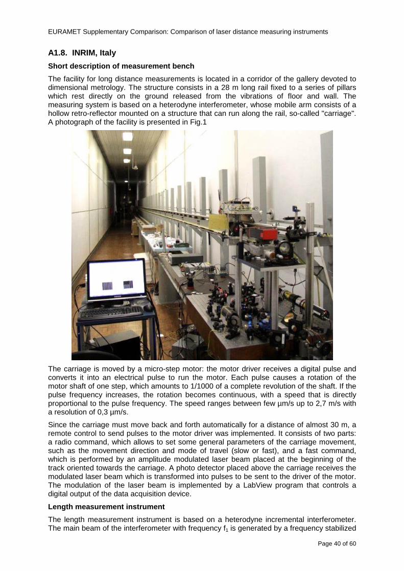
EURAMET Supplementary Comparison Comparison of laser distance measuring instruments
Page 40 of 60
A18 INRIM Italy
Short description of measurement bench
The facility for long distance measurements is located in a corridor of the gallery devoted to dimensional metrology The structure consists in a 28 m long rail fixed to a series of pillars which rest directly on the ground released from the vibrations of floor and wall The measuring system is based on a heterodyne interferometer whose mobile arm consists of a hollow retro-reflector mounted on a structure that can run along the rail so-called carriage A photograph of the facility is presented in Fig1
The carriage is moved by a micro-step motor the motor driver receives a digital pulse and converts it into an electrical pulse to run the motor Each pulse causes a rotation of the motor shaft of one step which amounts to 11000 of a complete revolution of the shaft If the pulse frequency increases the rotation becomes continuous with a speed that is directly proportional to the pulse frequency The speed ranges between few microms up to 27 ms with a resolution of 03 microms
Since the carriage must move back and forth automatically for a distance of almost 30 m a remote control to send pulses to the motor driver was implemented It consists of two parts a radio command which allows to set some general parameters of the carriage movement such as the movement direction and mode of travel (slow or fast) and a fast command which is performed by an amplitude modulated laser beam placed at the beginning of the track oriented towards the carriage A photo detector placed above the carriage receives the modulated laser beam which is transformed into pulses to be sent to the driver of the motor The modulation of the laser beam is implemented by a LabView program that controls a digital output of the data acquisition device
Length measurement instrument
The length measurement instrument is based on a heterodyne incremental interferometer The main beam of the interferometer with frequency f1 is generated by a frequency stabilized
EURAMET Supplementary Comparison Comparison of laser distance measuring instruments
Page 41 of 60
He-Ne laser calibrated with respect to the INRIM length standard and sent to the measurement arm the second beam is a portion of the first one diffracted by an acousto-optic modulator (AOM) with frequency f2 = f1 + 80 MHz The reference detector acquires the beat note signal at 80 MHz while the measurement detector acquires a signal at 80 MHz whose phase is varied due to the displacement of the retro-reflector moving on the rail In figure 2 the optical design of the interferometer is presented
Two different measuring techniques have been implemented
1 the ldquophase measuringrdquo technique based on fringes counting with a relative uncertainty of 5middot10-7 but limited at the maximum carriage speed of 3 cms
2 the ldquoDoppler frequency measurementrdquo technique for higher carriage speed based on the measurement of the Doppler frequency shift while the carriage runs
The second technique was validated by means of the comparison with the first technique at low speed with an agreement of the order of 3middot10-6 hence the Doppler frequency method could be considered validated within 01 mm over the whole rail path with the advantage of reducing the time needed to cover long distances so it was used for the EDM comparison
In order to obtain the distance covered by the carriage according to technique 2 the Doppler frequency is measured by a commercial high-performance counter (a Pendulum CNT-90) without dead time based on time stamping then it is converted in speed and integrated over time according to the following formula
( ) ( )int minus=minus= tffn
dtn
ffdairair
λλ
2
1
2
1
where d is the distance covered by the carriage f is the frequency of the measuring signal with the carriage at rest frsquo the frequency of the measuring signal with the carriage moving λi
is the wavelength of the laser in vacuum n - air is the air refractive index and ti is the integration time The difference frsquo-f is just the Doppler frequency due to the moving carriage
The time interval measurement resolution of the instrument is 100 ps and the time base is
EURAMET Supplementary Comparison Comparison of laser distance measuring instruments
Page 42 of 60
connected to the INRIM UTC so that the measurements of the Doppler frequency and the integration time are extremely accurate The environmental parameters such as air temperature atmospheric pressure partial pressure of water were monitored during the measurement process in order to calculate the value of air refractive index according to the Edlenrsquos formula
Comparison set-up
The different technical solutions adopted for the EDMs and for the target plate positioning are discussed in this paragraph and sketched in figure 3
Fig 3 picture of the EDM and target positioning area
Target plate positioning
In order to use the provided target plate an ad-hoc mounting was manufactured at INRIM it consists in a sort of picture frame made in aluminum which slightly clamps the target folded in half and gives it the necessary stiffness to be a reproducible target The upper part of the frame is L-shaped and allows it to be fixed to the carriage structure by means of two screws The rear part of the target mounting is depicted in figure 4 The target mounting was considered necessary because of the poor stiffness and planarity of the plastic target With the aluminium frame a planarity better than 01 mm was guaranteed The target plate is placed few centimetres next to the retro-reflector and normal to the interferometer beam axis since the EDM laser should be as close and parallel as possible to the reference beam
EURAMET Supplementary Comparison Comparison of laser distance measuring instruments
Page 43 of 60
Fig 4 picture of the rear part of the target plate mounting
EDMsrsquo positioning
The EDMs are placed on a cradle-like platform which is able to adjust the inclination of the EDM along the longitudinal axis (pitch angle) The platform height allows the EDMs to be at approx the same height as the interferometer beam A crucial role was played by the stop-wall placed behind the platform since it represents the ldquozero pointrdquo for all the length measurement Hence a particular effort was devoted to align the stop-wall so that it was normal to the interferometer beam axis and parallel to the target plate
Fig 5 detail of EDMsrsquo positioning the cradle-like platform and the stop-wall are well visible
EURAMET Supplementary Comparison Comparison of laser distance measuring instruments
Page 44 of 60
Target and stop-wall alignment
In order to have the stop-wall parallel to the target plate and normal to the interferometer beam axis the following procedure has been used
1) the stop-wall and the target plate were roughly placed trying to set them parallel and normal to the rail by eye (ie within few millimeters)
2) in order to check if the target was normal to the rail one EDM was positioned on the platform the pitch and yaw angles of the EDM were adjusted by observing the position of the EDM laser spot on the target plate when the target is moved along the rail fixed position means laser beam parallel to the carriage movement Then the target was moved until the end of the rail and a thin mirror was kept in contact with it hence observing the EDM laser reflected by the mirror it was possible to adjust the target tilt acting on the screws until the laser beam is reflected back to the source
3) finally in order to check the parallelism between the stop-wall and the target a tool made by a laser pointing orthogonally to its base was used the base was leant against the stop-wall and the laser was centered on the target when the target is near then the target was moved until the end of the rail hence observing the spot of the laser on the target it was possible to adjust the stop-wall orientation
The residual misalignment errors which we were not able to eliminate were kept into account in the uncertainty budget
Measurement of the first 30 cm
Due to the geometry of our set-up it was not possible to perform the first point of measurement by means of the interferometer indeed the carriage (hence the target) is not able to go in contact with the stop-wall
Fig 6 measurement of the first 30 cm the ruler touching the stop-wall and the target and the mechanical probe (in the back) touching the carriage are visible
EURAMET Supplementary Comparison Comparison of laser distance measuring instruments
Page 45 of 60
So a ruler made of aluminum with rounded ends and nominal length equal to 30 cm was adopted to set the distance between the target plate and the stop-wall for the first point of measurement as it is shown in figure 6 The ruler whose length was measured by a CMM machine was inserted between the target and the stop-wall leaning against the latter and the carriage was carefully moved towards the stop-wall until the target lightly touched the ruler A mechanical probe that touches the carriage structure when carriage is in the ldquo30 cmrdquo position was used as a reference measurement to check the repeatability of this distance after each measurement set
Fig 7 detail of the mechanical probe touching the carriage
Environmental parameters
The environmental parameters such as air temperature atmospheric pressure and humidity were monitored during the whole measurement process in order to calculate the value of air refractive index according to the Edlenrsquos formula
Among these parameters the temperature distribution along the mobile arm of the interferometer was our main concern mainly for two reasons
1 the temperature control of the gallery was not perfectly working during the measurement period so temperature drifts had to be monitored
2 longitudinal temperature gradients due to non uniform heating and to the presence of electronic instruments were pretty high
To the purpose 14 thermometers were uniformly dislocated along the rail and automatically recorded for all the measurement period Both temporal drifts and gradients along the path have been taken in account in the uncertainty budget In any case maximum temperature differences along the rail are within 1 degC In fig 8 an extract from the acquisition file is shown
Unfortunately the air conditioning system did not work well during the measurement campaign hence the measurements were performed at a mean temperature of 209 degC
EURAMET Supplementary Comparison Comparison of laser distance measuring instruments
Page 46 of 60
Fig 8 each curve represents the temperature distribution along the rail during the measurements campaign
Carriage waving
Since the rail is not perfectly straight and the measurement laser is not coincident with the measurement beam the Abbegrave error due to waving of the target must be considered A quantitative measurement and a qualitative measurement were carried out With an electronic level placed on the carriage the straightness on the vertical plane has been mapped with a half meter resolution (the data are reported in fig 9) With a laser placed on the carriage the horizontal and vertical waving are qualitatively compared by looking at the movements of the light spot on a target fixed to the rail end As a conclusion the horizontal and vertical waving are comparable in magnitude and the peak to peak error is of the order of 300 arcseconds
Fig 9 vertical waving of the target measured by an electronic level placed on the carriage
EURAMET Supplementary Comparison Comparison of laser distance measuring instruments
Page 47 of 60
Measurement procedure
The measurements were carried out according to the following procedure
The target was set in the starting position with the procedure described above
In sequence the four EDMs are positioned on the base the horizontal and vertical tilt are adjusted and the distance measurement is recorded An additional fifth EDM (Bosh DLE 150 property of INRiM) was included in the measurement sequence Each EDM is placed on the base and gently pushed against the reference wall in such a way that the measurement laser beam starting point is the same for all EDMs Than the horizontal and vertical angles were adjusted in order to hit the central point of the target indicated with two black marks (see pictures 3 and 6) with ldquovisualrdquo alignment The measurement button is then pressed several times (typically 5) and the average reading is recorded Typical dispersion between readings is within few last digit units In case the dispersion between readings is too large the anomaly is recorded
The carriage was then moved in the next position (about 5 m) and the measurement sequence was repeated for the 5 EDMs The operation is repeated up to 25 m The 25 m measurement is than repeated again as well as all the points till the first one so that each point is measured twice each set Since the carriage movement is ldquoopen looprdquo the positioning of the carriage was not exactly in the nominal 5 m intervals For each positioning the incremental displacement is measured by the interferometer in the Doppler mode Finally the measured values were averaged in order to give a single value for each nominal position
At the end of the measurement set when the carriage is at the 30 cm position again the sum of the interferometric measurements should be very close to zero The residual value is compared with the difference between the first and the final measurements of the mechanical probe The difference must be within the uncertainty of the Doppler technique otherwise some error occurred in the measurement set that must be repeated
At the end of the session 10 complete sets of measurements recorded from the 20th to the 30th of January 2012 have been considered for this report
Additional remarks
Effect of laser pointing
During a preliminary set of measurements we noticed a strong and unexpected dependence of the measurement result on the position of the laser spot on the target Indeed since no particular instructions were given about the relative position of the laser spot on target position (except to exclude the central joint between the two halves) we decided to work relatively close to the right side of the target -closer to the interferometer beam- in order to reduce the Abbegrave error We noticed very large errors at large distances in particular of the Leica DISTO D3a (see figure 10)
EURAMET Supplementary Comparison Comparison of laser distance measuring instruments
Page 48 of 60
Fig 10 errors of each EDM In a preliminary set of measurements
We also noticed that this error was strongly dependent on the position of the spot on the target For this reason we carried out a set of measurements at the maximum length in different positions of the target from one edge to the other according to figure 11 The results are reported in table V
EDM A B C D E
Leica D3a -4 +1 0 +24 +43
+2 0 +42 +40
-1 0 +38
Leica D8 0 0 0 2 +7
0 +12 +23
table V deviations (in mm) from the length measured at point C aiming the laser spot at different positions of the target (notations as in figure 11)
We tried to find an explanation to this effect in the shape of the laser spot if the spot was
EURAMET Supplementary Comparison Comparison of laser distance measuring instruments
Page 49 of 60
particularly defocused or had high diffraction some of the energy could fall out of the target and affect the measurement result In fact the images of the spots (shown in fig 12) do not support this hypothesis Finally we decided to use the center of the (half) target for the comparison
Changing the target
In order to investigate the influence of the target on the measurements a cardboard foil (400 x 400) mm was fixed to the target mounting and a complete set of measurements was performed The results reported in figure 13 and 14 do not show any evidence of a possible dependency of the EDM measurement on the target kind
EURAMET Supplementary Comparison Comparison of laser distance measuring instruments
Page 50 of 60
Measurement at 50 m
Although we are not able to perform traceable length measurements beyond 28 m we wanted to get a sense of EDMs behaviour at longer distances So a target (represented by a rack side wall) was placed at approximately 50 m one after the other the EDMrsquos were positioned on the base and pointed towards the target The measurements were repeated then the target was replaced by the target used for the comparison and a third set of measurements were performed To our great surprise all the EDMrsquos were in good agreement (within 2 or 3 mm for each set of measurement) even those which showed errors of the order of five to ten millimeters at 25 m namely BOSCH DLE 50 and LEICA DISTO D3a Therefore each set of measurements was averaged and the deviations from the mean value are reported in figure 15
EURAMET Supplementary Comparison Comparison of laser distance measuring instruments
Page 51 of 60
Fig 15 Deviations from average value of the measurements At 50 m
EURAMET Supplementary Comparison Comparison of laser distance measuring instruments
Page 52 of 60
A19 CEM Spain
Short description of the measurement bench
To make the measurements of EDMs we have used a reference line made of adjustable supports fixed on a wall of the laboratory Each support is nominally separated five metres from the previous one so we can generate reference lengths up to fifty metres with a pitch of five metres The supports are designed to accommodate both targets and handheld EDMs Distances between supports were measured by using a total station traced to national standards The relative angles of the bases have been measured and corrected
Fig 1 - View of three consecutive supports of the 50 m baseline (left) Lab technician situating an EDM on the first support of the baseline (right)
Length measurement instrument
The baseline was calibrated by using a total station Leica TDA5005 with spherical reflector the calibration uncertainty being 02 mm for k = 2
The target is provided by the comparison The quality of the target was judged as not good due to geometrical constructive errors and the lack of rigidity and stability We measured the flatness of the target surface the distance edge-surface and the angle between them by using a 3D coordinate measuring machine The results of flatness and angle were included in the uncertainty budget and the distance EDM-target was corrected for each EDM due to each beam impinged on a different point of the target
We were not able to measure the distance 0 to 03 m because the baseline pitch is 5 meters and although we are able to measure shorter values in a different facility the target was not appropriate for our bench
EURAMET Supplementary Comparison Comparison of laser distance measuring instruments
Page 53 of 60
Fig 2 - View of an EDM on the first support of the baseline (left) A closer look showing the support adjustments and the origin plate (right)
Fig 3 - View of the comparison target on one of the supports of the baseline (left) A closer look showing the target edge against the support rigid reference (right)
Measurement method
The measurements were carried out by comparison against the known values of the calibrated baseline (metallic references on supports)
Environmental conditions were maintained within the following limits
- Temperature 20 ordmC plusmn 05 ordmC
- Humidity 45 plusmn 10
Each laser distance measuring instrument was placed at the first support of the base and aligned so that the laser beam was perpendicular to the target as indicated by the comparison protocol
For each measurement we took the average of thirty measurements It permitted us to evaluate the repeatability of the instrument
EURAMET Supplementary Comparison Comparison of laser distance measuring instruments
Page 54 of 60
A110 BEV Austria
Short description of the measurement bench
Fig 1 Carriage of tape bench View from the laser interferometer side Retroreflector mounted on the vertical plate the EDM target is mounted on the backside
Fig 2 Support for the DUT Adjustable with 2 translational and 2 rotational degrees of freedom respectively
Fig 3 Setting of the 300 mm starting position Note the rough-and-ready mounted target plate
Fig 4 Laser interferometer side of the bench The DUT is 50 m away on the other side
EURAMET Supplementary Comparison Comparison of laser distance measuring instruments
Page 55 of 60
Measurement procedure 1 The EDM is positioned with the help of a 4-axis positioning stage so that its laser beam is
coaxial with the measurement direction of the laser interferometer (in head on configuration)
2 The EDM is removed from its support The bench carriage is positioned so that the distance of the target plate from the EDM back support is 300 mm A length bar with spherical faces is used for this adjustment The laser interferometer is preset to 300 mm and the EDM is put back on its support
3 At each position 10 consecutive measurements are taken (repeatability) and the carriage is moved to the next position The carriage is manually moved under control of the laser interferometer until it is within plusmn30 microm at the correct position (Exception for the DLE 150 the target is not positioned at 10 m but at 10 m ndash 1 mm to make use of the higher resolution) The indicated (not the nominal) distance of the laser interferometer is recorded for the determination of the deviation
4 After reaching the 50 m position all points are measured in reverse order (bidirectional) Immediately after the last measurement the EDM is removed and the indication using the 300 mm length bar is checked (thus noting a possible drift of the setup)
5 Each instrument was measured 4 times according to this procedure on different days (reproducibility of bench and instrument)
Length measurement instrument
Agilent laser interferometer with long range option The bench was completed short time before performing these measurement So the characterisation was not complete and the respective measurement uncertainty of the laser interferometer is estimated rather high But anyway its contribution to the overall uncertainty can nearly be neglected
Additional remarks
The uncertainty originating from the DUT is the dominating uncertainty contribution Specifically the resolution of the two Bosch instruments (1 mm) and the repeatability are the largest contributions For the DLA 50 the pooled standard deviation of a reading at 50 m is larger than 2 mm Moreover the length dependence is not a simple function
All of the instruments show a significant deviation of the laser beam from the normal of the back (reference) face of the instrument The measured angles reach from 04deg (D3a) to 11deg (DLE 50) This leads depending on the outer dimensions of the instruments to a constant uncertainty contribution of 02 mm in our setup It must be noted that the reference faces are not well defined in most of the instruments
The reproducibility is quite different for the four instruments so only part of it originates from the setup For CMC claims we will use the standard uncertainty value of the most reproducible instrument (D3a) which amounts to 013 mm For an ideal instrument with a resolution of 01 mm and perfect repeatability we would thus have a constant expanded uncertainty of 053 mm up to 50 m
EURAMET Supplementary Comparison Comparison of laser distance measuring instruments
Page 56 of 60
A111 JV Norway
Short description of measurement bench
EDM under calibration and the reference system are aligned along a 50 m measurement bench with rails to carry the linear movement of a target plate for the EDM and a corner cube reflector for the reference system The distance between parallel axis of EDM and axis of the reference system is 130 mm Abbe error due to angle errors for the movement is smaller than 01 mm and is corrected for at each measurement point At long lengths an aperture is used approximately midway between the target plate and the EDM to avoid interfering stray light to the EDM
Alignment procedure
1) Alignment of reference system to the movement of the carriage (rails)
2) Alignment of the EDM to the movement of the carriage (rails)
3) Alignment of a plane mirror at the position of the target plate using back-reflection to the EDM output (normal incident of light on the mirror)
4) Take out the EDM and align the zero reference plate at the back of the EDM to the plane mirror
5) The mirror is replaced by the target plate and the target plate is aligned to the zero reference plate
6) Zero setting of the reference measurement system when target plate is at zero distance to the reference plate at the back of the EDM
7) Put the EDM back in position and realign it to the movement of the carriage (rails)
8) Zero setting of the EDM to the reference plate
Image 1) Image 2) Image 3) Image 4)
Image 1) Items 5) ndash 6) in alignment procedure
Fixture for HP linear interferometer is seen bottom right Part of Wyler instrument is seen to the left blue colour
Image 2) Items 7) and 8) in alignment procedure
Micrometer screws for angle alignment in two directions and linear translation for zero setting of the EDM Push button on the EDM is positioned at the tilting point of the angle adjustment table to maximize stability during measurement HP 5519 A laser head is seen to the right
Image 3) Ready to measure at selected distances from zero point the reference plate
Image 4) EDM spot size at 50 m
Length measurement instrument
- Hewlett Packard Dynamic Calibrator 5519 A (max range 80 m)
- Pressure air temperature humidity Vaisala
EURAMET Supplementary Comparison Comparison of laser distance measuring instruments
Page 57 of 60
- Digital high resolution angle measurement Wyler
I used our own target plate which is of the same type as enclosed in the artefact suitcase article number 766560 from Leica but with reduced size width x hight = 90 x 137 mm
The zero reference plate is of similar type and size
Before measurements batteries of EDMs were switched to new batteries Old batteries are switched back after calibration
For L gt 5 m an aperture of similar size as the target plate is used approximately midway between the EDM and the target plate
Additional remarks
Reports on EDM indicated values at each measurement point is the average value of n = 5 repetitions A linear model of the standard deviation for the repeatability of the EDM readings at different lengths is estimated using m = 20 repetitions at least 5 positions along the scale An estimate of the length dependent repeatability is made for each instrument
The expanded uncertainty U(95) is rounded up to the limiting resolution of 1 mm in the interval 10 m to 40 m for Bosch GLM 150
After the calibration we also estimated the angle error of the optical axis of the EDM to its back plane (back reference of EDM) Bosch DLE 50 26 mrad up measured at 50 m Bosch GLM 150 8 mrad to the left measured at 50 m Leica DISTO D3a 37 mrad down measured at 20 m Leica DISTO D8 2 mrad to the left and 4 mrad down (45 mrad total) measured at 20 m
The distance between parallel walls will be measured too large if the back plane is assumed to be normal to the optical axis of the EDM by ∆LL = (1cosα ndash 1) Bosch DLE 50 ∆LL = 340 ppm (∆L = 17 mm at L = 50 m) Bosch GLM 150 ∆LL = 32 ppm (∆L = 16 mm at L = 50 m) Leica DISTO D3a ∆LL = 7 ppm (∆L = 034 mm at L = 50 m) Leica DISTO D8 ∆LL = 10 ppm (∆L = 05 mm at L = 50 m)
EURAMET Supplementary Comparison Comparison of laser distance measuring instruments
Page 58 of 60
A112 METAS Switzerland
Short description of measurement bench (photo recom mended)
50 m bench with laser interferometer (see photo detailed description in Michel Degoumois Un Long laboratoire de mesure OFMETinfo Vol5 No 2 1998)
Length measurement instrument
HP 5529 B laser interferometer range 80 m
EURAMET Supplementary Comparison Comparison of laser distance measuring instruments
Page 59 of 60
A113 GUM Poland
Short description of measurement bench
The 50 m bench is situated in the corridor laboratory located in the basement and has its own air conditioning system with air temperature 20 plusmn 1 degC and humidity 50 plusmn 10 RH The measuring carriage is carried microscope with CCD camera and the optics associated with the interferometer The carriage is driven using belt-transmission and electrical engine with remote ndash controlled variable speed drive
The EDM was placed on the fixed adjustable plate on the other end than laser interferometer The target plate of the EDM was placed on the measuring carriage For each EDM 3 series of measurement were done Before the each measurement EDM was repositioned and aligned again
Length measurement instrument
1 Laser interferometer HP 5529A with long-range option laser head HP 5519A
2 Ambient measurement system number and location of sensors - 20 air temperature sensors type YSI with KEITHLEY multimeter they are placed very
close to axis of the laser beam - air pressure and humidity are measured with Vaisala barometer and
thermohigrometer - CO2 content was measured with analyzer made by Intelli Charge type SPN 4462
EURAMET Supplementary Comparison Comparison of laser distance measuring instruments
Page 60 of 60
Appendix 2 Corrections of reports
131 CEM Spain
CEM reported two errors in their report
1) Bosch GLM 150 EDM error for 35 m should be -08 mm instead of the indicated 08 mm
2) Leica DISTO D8 EDM error for 35 m should be -019 mm instead of the indicated 019 mm
Proposed corrections have been included in Tables 2 and 4 of the Final Report
132 AS Metrosert Estonia
AS Metrosert reported mixed up of all results for Bosch DLE 50 and Bosch GLM 150 The results and uncertainties sent for DLE 50 was results for GLM 150 and vice versa
Proposed corrections have been included in Tables 1 and 2 of the Final Report
133 INRIM Italy
Among the data reported from INRIM some anomalies were found in the measurements of BOSCH DLE 50 and LEICA DISTO D3a at distances of 20 and 25 m
After preliminary discussion on Draft A it was understood that those anomalies could be explained as a sensitivity of said instruments to the laser light that once diffused by the target is reflected by surfaces parallel to the measurement axis and detected together with the wanted signal The superimposition of the two signals can cause a ldquopullingrdquo effect leading to an overestimation of the distance being the reflected path always longer than the direct one Indeed in the INRIMrsquos set-up the target was mounted pretty close to the flat rail used for the carriage movement being likely responsible for unwanted reflections that disturbed the measurements
Since the errors reported in INRIMrsquos measurements can be ascribed to a defect of BOSCH DLE 50 and LEICA DISTO D3a andor to a lack of description of the working conditions of said instruments INRIM asked to eliminate its measurement points at 20 and 25 m of said instruments from the comparison
Proposed corrections have been included in Tables 1 and 3 of the Final Report
134 JV Norway
Justervesenet has changed the procedure and introduced two apertures instead of only one aperture (iris) which was positioned at half distance between EDM and target The reason is that the reference beam also has an aperture and it is positioned right below the beam from the EDM (130 mm distance between axes) Some diffusively reflected stray light from the EDM target might enter the aperture for the reference beam reflect at the measurement table and reach the detector of the EDM In our calibration set-up we have only seen problems at L gt 30 m We will position the first aperture at ca 5 m from the EDM and then the second aperture at ca 25 m This combination of two apertures will effectively eliminate interference of stray light from the measurement table to the EDM detector for all lengths up to 50 m
Justervesenet also increases the uncertainty component regarding repeatability reproducibility so that the expanded uncertainty increases from 14 mm to 15 mm
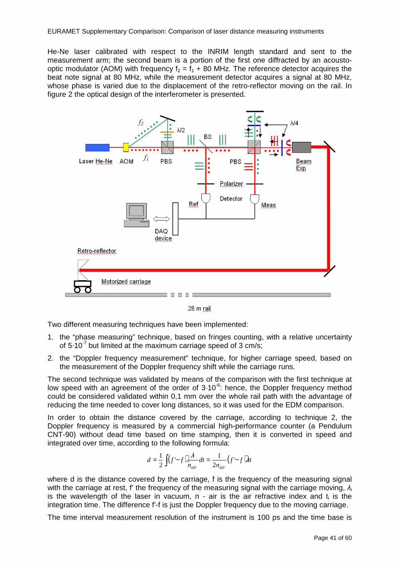
EURAMET Supplementary Comparison Comparison of laser distance measuring instruments
Page 41 of 60
He-Ne laser calibrated with respect to the INRIM length standard and sent to the measurement arm the second beam is a portion of the first one diffracted by an acousto-optic modulator (AOM) with frequency f2 = f1 + 80 MHz The reference detector acquires the beat note signal at 80 MHz while the measurement detector acquires a signal at 80 MHz whose phase is varied due to the displacement of the retro-reflector moving on the rail In figure 2 the optical design of the interferometer is presented
Two different measuring techniques have been implemented
1 the ldquophase measuringrdquo technique based on fringes counting with a relative uncertainty of 5middot10-7 but limited at the maximum carriage speed of 3 cms
2 the ldquoDoppler frequency measurementrdquo technique for higher carriage speed based on the measurement of the Doppler frequency shift while the carriage runs
The second technique was validated by means of the comparison with the first technique at low speed with an agreement of the order of 3middot10-6 hence the Doppler frequency method could be considered validated within 01 mm over the whole rail path with the advantage of reducing the time needed to cover long distances so it was used for the EDM comparison
In order to obtain the distance covered by the carriage according to technique 2 the Doppler frequency is measured by a commercial high-performance counter (a Pendulum CNT-90) without dead time based on time stamping then it is converted in speed and integrated over time according to the following formula
( ) ( )int minus=minus= tffn
dtn
ffdairair
λλ
2
1
2
1
where d is the distance covered by the carriage f is the frequency of the measuring signal with the carriage at rest frsquo the frequency of the measuring signal with the carriage moving λi
is the wavelength of the laser in vacuum n - air is the air refractive index and ti is the integration time The difference frsquo-f is just the Doppler frequency due to the moving carriage
The time interval measurement resolution of the instrument is 100 ps and the time base is
EURAMET Supplementary Comparison Comparison of laser distance measuring instruments
Page 42 of 60
connected to the INRIM UTC so that the measurements of the Doppler frequency and the integration time are extremely accurate The environmental parameters such as air temperature atmospheric pressure partial pressure of water were monitored during the measurement process in order to calculate the value of air refractive index according to the Edlenrsquos formula
Comparison set-up
The different technical solutions adopted for the EDMs and for the target plate positioning are discussed in this paragraph and sketched in figure 3
Fig 3 picture of the EDM and target positioning area
Target plate positioning
In order to use the provided target plate an ad-hoc mounting was manufactured at INRIM it consists in a sort of picture frame made in aluminum which slightly clamps the target folded in half and gives it the necessary stiffness to be a reproducible target The upper part of the frame is L-shaped and allows it to be fixed to the carriage structure by means of two screws The rear part of the target mounting is depicted in figure 4 The target mounting was considered necessary because of the poor stiffness and planarity of the plastic target With the aluminium frame a planarity better than 01 mm was guaranteed The target plate is placed few centimetres next to the retro-reflector and normal to the interferometer beam axis since the EDM laser should be as close and parallel as possible to the reference beam
EURAMET Supplementary Comparison Comparison of laser distance measuring instruments
Page 43 of 60
Fig 4 picture of the rear part of the target plate mounting
EDMsrsquo positioning
The EDMs are placed on a cradle-like platform which is able to adjust the inclination of the EDM along the longitudinal axis (pitch angle) The platform height allows the EDMs to be at approx the same height as the interferometer beam A crucial role was played by the stop-wall placed behind the platform since it represents the ldquozero pointrdquo for all the length measurement Hence a particular effort was devoted to align the stop-wall so that it was normal to the interferometer beam axis and parallel to the target plate
Fig 5 detail of EDMsrsquo positioning the cradle-like platform and the stop-wall are well visible
EURAMET Supplementary Comparison Comparison of laser distance measuring instruments
Page 44 of 60
Target and stop-wall alignment
In order to have the stop-wall parallel to the target plate and normal to the interferometer beam axis the following procedure has been used
1) the stop-wall and the target plate were roughly placed trying to set them parallel and normal to the rail by eye (ie within few millimeters)
2) in order to check if the target was normal to the rail one EDM was positioned on the platform the pitch and yaw angles of the EDM were adjusted by observing the position of the EDM laser spot on the target plate when the target is moved along the rail fixed position means laser beam parallel to the carriage movement Then the target was moved until the end of the rail and a thin mirror was kept in contact with it hence observing the EDM laser reflected by the mirror it was possible to adjust the target tilt acting on the screws until the laser beam is reflected back to the source
3) finally in order to check the parallelism between the stop-wall and the target a tool made by a laser pointing orthogonally to its base was used the base was leant against the stop-wall and the laser was centered on the target when the target is near then the target was moved until the end of the rail hence observing the spot of the laser on the target it was possible to adjust the stop-wall orientation
The residual misalignment errors which we were not able to eliminate were kept into account in the uncertainty budget
Measurement of the first 30 cm
Due to the geometry of our set-up it was not possible to perform the first point of measurement by means of the interferometer indeed the carriage (hence the target) is not able to go in contact with the stop-wall
Fig 6 measurement of the first 30 cm the ruler touching the stop-wall and the target and the mechanical probe (in the back) touching the carriage are visible
EURAMET Supplementary Comparison Comparison of laser distance measuring instruments
Page 45 of 60
So a ruler made of aluminum with rounded ends and nominal length equal to 30 cm was adopted to set the distance between the target plate and the stop-wall for the first point of measurement as it is shown in figure 6 The ruler whose length was measured by a CMM machine was inserted between the target and the stop-wall leaning against the latter and the carriage was carefully moved towards the stop-wall until the target lightly touched the ruler A mechanical probe that touches the carriage structure when carriage is in the ldquo30 cmrdquo position was used as a reference measurement to check the repeatability of this distance after each measurement set
Fig 7 detail of the mechanical probe touching the carriage
Environmental parameters
The environmental parameters such as air temperature atmospheric pressure and humidity were monitored during the whole measurement process in order to calculate the value of air refractive index according to the Edlenrsquos formula
Among these parameters the temperature distribution along the mobile arm of the interferometer was our main concern mainly for two reasons
1 the temperature control of the gallery was not perfectly working during the measurement period so temperature drifts had to be monitored
2 longitudinal temperature gradients due to non uniform heating and to the presence of electronic instruments were pretty high
To the purpose 14 thermometers were uniformly dislocated along the rail and automatically recorded for all the measurement period Both temporal drifts and gradients along the path have been taken in account in the uncertainty budget In any case maximum temperature differences along the rail are within 1 degC In fig 8 an extract from the acquisition file is shown
Unfortunately the air conditioning system did not work well during the measurement campaign hence the measurements were performed at a mean temperature of 209 degC
EURAMET Supplementary Comparison Comparison of laser distance measuring instruments
Page 46 of 60
Fig 8 each curve represents the temperature distribution along the rail during the measurements campaign
Carriage waving
Since the rail is not perfectly straight and the measurement laser is not coincident with the measurement beam the Abbegrave error due to waving of the target must be considered A quantitative measurement and a qualitative measurement were carried out With an electronic level placed on the carriage the straightness on the vertical plane has been mapped with a half meter resolution (the data are reported in fig 9) With a laser placed on the carriage the horizontal and vertical waving are qualitatively compared by looking at the movements of the light spot on a target fixed to the rail end As a conclusion the horizontal and vertical waving are comparable in magnitude and the peak to peak error is of the order of 300 arcseconds
Fig 9 vertical waving of the target measured by an electronic level placed on the carriage
EURAMET Supplementary Comparison Comparison of laser distance measuring instruments
Page 47 of 60
Measurement procedure
The measurements were carried out according to the following procedure
The target was set in the starting position with the procedure described above
In sequence the four EDMs are positioned on the base the horizontal and vertical tilt are adjusted and the distance measurement is recorded An additional fifth EDM (Bosh DLE 150 property of INRiM) was included in the measurement sequence Each EDM is placed on the base and gently pushed against the reference wall in such a way that the measurement laser beam starting point is the same for all EDMs Than the horizontal and vertical angles were adjusted in order to hit the central point of the target indicated with two black marks (see pictures 3 and 6) with ldquovisualrdquo alignment The measurement button is then pressed several times (typically 5) and the average reading is recorded Typical dispersion between readings is within few last digit units In case the dispersion between readings is too large the anomaly is recorded
The carriage was then moved in the next position (about 5 m) and the measurement sequence was repeated for the 5 EDMs The operation is repeated up to 25 m The 25 m measurement is than repeated again as well as all the points till the first one so that each point is measured twice each set Since the carriage movement is ldquoopen looprdquo the positioning of the carriage was not exactly in the nominal 5 m intervals For each positioning the incremental displacement is measured by the interferometer in the Doppler mode Finally the measured values were averaged in order to give a single value for each nominal position
At the end of the measurement set when the carriage is at the 30 cm position again the sum of the interferometric measurements should be very close to zero The residual value is compared with the difference between the first and the final measurements of the mechanical probe The difference must be within the uncertainty of the Doppler technique otherwise some error occurred in the measurement set that must be repeated
At the end of the session 10 complete sets of measurements recorded from the 20th to the 30th of January 2012 have been considered for this report
Additional remarks
Effect of laser pointing
During a preliminary set of measurements we noticed a strong and unexpected dependence of the measurement result on the position of the laser spot on the target Indeed since no particular instructions were given about the relative position of the laser spot on target position (except to exclude the central joint between the two halves) we decided to work relatively close to the right side of the target -closer to the interferometer beam- in order to reduce the Abbegrave error We noticed very large errors at large distances in particular of the Leica DISTO D3a (see figure 10)
EURAMET Supplementary Comparison Comparison of laser distance measuring instruments
Page 48 of 60
Fig 10 errors of each EDM In a preliminary set of measurements
We also noticed that this error was strongly dependent on the position of the spot on the target For this reason we carried out a set of measurements at the maximum length in different positions of the target from one edge to the other according to figure 11 The results are reported in table V
EDM A B C D E
Leica D3a -4 +1 0 +24 +43
+2 0 +42 +40
-1 0 +38
Leica D8 0 0 0 2 +7
0 +12 +23
table V deviations (in mm) from the length measured at point C aiming the laser spot at different positions of the target (notations as in figure 11)
We tried to find an explanation to this effect in the shape of the laser spot if the spot was
EURAMET Supplementary Comparison Comparison of laser distance measuring instruments
Page 49 of 60
particularly defocused or had high diffraction some of the energy could fall out of the target and affect the measurement result In fact the images of the spots (shown in fig 12) do not support this hypothesis Finally we decided to use the center of the (half) target for the comparison
Changing the target
In order to investigate the influence of the target on the measurements a cardboard foil (400 x 400) mm was fixed to the target mounting and a complete set of measurements was performed The results reported in figure 13 and 14 do not show any evidence of a possible dependency of the EDM measurement on the target kind
EURAMET Supplementary Comparison Comparison of laser distance measuring instruments
Page 50 of 60
Measurement at 50 m
Although we are not able to perform traceable length measurements beyond 28 m we wanted to get a sense of EDMs behaviour at longer distances So a target (represented by a rack side wall) was placed at approximately 50 m one after the other the EDMrsquos were positioned on the base and pointed towards the target The measurements were repeated then the target was replaced by the target used for the comparison and a third set of measurements were performed To our great surprise all the EDMrsquos were in good agreement (within 2 or 3 mm for each set of measurement) even those which showed errors of the order of five to ten millimeters at 25 m namely BOSCH DLE 50 and LEICA DISTO D3a Therefore each set of measurements was averaged and the deviations from the mean value are reported in figure 15
EURAMET Supplementary Comparison Comparison of laser distance measuring instruments
Page 51 of 60
Fig 15 Deviations from average value of the measurements At 50 m
EURAMET Supplementary Comparison Comparison of laser distance measuring instruments
Page 52 of 60
A19 CEM Spain
Short description of the measurement bench
To make the measurements of EDMs we have used a reference line made of adjustable supports fixed on a wall of the laboratory Each support is nominally separated five metres from the previous one so we can generate reference lengths up to fifty metres with a pitch of five metres The supports are designed to accommodate both targets and handheld EDMs Distances between supports were measured by using a total station traced to national standards The relative angles of the bases have been measured and corrected
Fig 1 - View of three consecutive supports of the 50 m baseline (left) Lab technician situating an EDM on the first support of the baseline (right)
Length measurement instrument
The baseline was calibrated by using a total station Leica TDA5005 with spherical reflector the calibration uncertainty being 02 mm for k = 2
The target is provided by the comparison The quality of the target was judged as not good due to geometrical constructive errors and the lack of rigidity and stability We measured the flatness of the target surface the distance edge-surface and the angle between them by using a 3D coordinate measuring machine The results of flatness and angle were included in the uncertainty budget and the distance EDM-target was corrected for each EDM due to each beam impinged on a different point of the target
We were not able to measure the distance 0 to 03 m because the baseline pitch is 5 meters and although we are able to measure shorter values in a different facility the target was not appropriate for our bench
EURAMET Supplementary Comparison Comparison of laser distance measuring instruments
Page 53 of 60
Fig 2 - View of an EDM on the first support of the baseline (left) A closer look showing the support adjustments and the origin plate (right)
Fig 3 - View of the comparison target on one of the supports of the baseline (left) A closer look showing the target edge against the support rigid reference (right)
Measurement method
The measurements were carried out by comparison against the known values of the calibrated baseline (metallic references on supports)
Environmental conditions were maintained within the following limits
- Temperature 20 ordmC plusmn 05 ordmC
- Humidity 45 plusmn 10
Each laser distance measuring instrument was placed at the first support of the base and aligned so that the laser beam was perpendicular to the target as indicated by the comparison protocol
For each measurement we took the average of thirty measurements It permitted us to evaluate the repeatability of the instrument
EURAMET Supplementary Comparison Comparison of laser distance measuring instruments
Page 54 of 60
A110 BEV Austria
Short description of the measurement bench
Fig 1 Carriage of tape bench View from the laser interferometer side Retroreflector mounted on the vertical plate the EDM target is mounted on the backside
Fig 2 Support for the DUT Adjustable with 2 translational and 2 rotational degrees of freedom respectively
Fig 3 Setting of the 300 mm starting position Note the rough-and-ready mounted target plate
Fig 4 Laser interferometer side of the bench The DUT is 50 m away on the other side
EURAMET Supplementary Comparison Comparison of laser distance measuring instruments
Page 55 of 60
Measurement procedure 1 The EDM is positioned with the help of a 4-axis positioning stage so that its laser beam is
coaxial with the measurement direction of the laser interferometer (in head on configuration)
2 The EDM is removed from its support The bench carriage is positioned so that the distance of the target plate from the EDM back support is 300 mm A length bar with spherical faces is used for this adjustment The laser interferometer is preset to 300 mm and the EDM is put back on its support
3 At each position 10 consecutive measurements are taken (repeatability) and the carriage is moved to the next position The carriage is manually moved under control of the laser interferometer until it is within plusmn30 microm at the correct position (Exception for the DLE 150 the target is not positioned at 10 m but at 10 m ndash 1 mm to make use of the higher resolution) The indicated (not the nominal) distance of the laser interferometer is recorded for the determination of the deviation
4 After reaching the 50 m position all points are measured in reverse order (bidirectional) Immediately after the last measurement the EDM is removed and the indication using the 300 mm length bar is checked (thus noting a possible drift of the setup)
5 Each instrument was measured 4 times according to this procedure on different days (reproducibility of bench and instrument)
Length measurement instrument
Agilent laser interferometer with long range option The bench was completed short time before performing these measurement So the characterisation was not complete and the respective measurement uncertainty of the laser interferometer is estimated rather high But anyway its contribution to the overall uncertainty can nearly be neglected
Additional remarks
The uncertainty originating from the DUT is the dominating uncertainty contribution Specifically the resolution of the two Bosch instruments (1 mm) and the repeatability are the largest contributions For the DLA 50 the pooled standard deviation of a reading at 50 m is larger than 2 mm Moreover the length dependence is not a simple function
All of the instruments show a significant deviation of the laser beam from the normal of the back (reference) face of the instrument The measured angles reach from 04deg (D3a) to 11deg (DLE 50) This leads depending on the outer dimensions of the instruments to a constant uncertainty contribution of 02 mm in our setup It must be noted that the reference faces are not well defined in most of the instruments
The reproducibility is quite different for the four instruments so only part of it originates from the setup For CMC claims we will use the standard uncertainty value of the most reproducible instrument (D3a) which amounts to 013 mm For an ideal instrument with a resolution of 01 mm and perfect repeatability we would thus have a constant expanded uncertainty of 053 mm up to 50 m
EURAMET Supplementary Comparison Comparison of laser distance measuring instruments
Page 56 of 60
A111 JV Norway
Short description of measurement bench
EDM under calibration and the reference system are aligned along a 50 m measurement bench with rails to carry the linear movement of a target plate for the EDM and a corner cube reflector for the reference system The distance between parallel axis of EDM and axis of the reference system is 130 mm Abbe error due to angle errors for the movement is smaller than 01 mm and is corrected for at each measurement point At long lengths an aperture is used approximately midway between the target plate and the EDM to avoid interfering stray light to the EDM
Alignment procedure
1) Alignment of reference system to the movement of the carriage (rails)
2) Alignment of the EDM to the movement of the carriage (rails)
3) Alignment of a plane mirror at the position of the target plate using back-reflection to the EDM output (normal incident of light on the mirror)
4) Take out the EDM and align the zero reference plate at the back of the EDM to the plane mirror
5) The mirror is replaced by the target plate and the target plate is aligned to the zero reference plate
6) Zero setting of the reference measurement system when target plate is at zero distance to the reference plate at the back of the EDM
7) Put the EDM back in position and realign it to the movement of the carriage (rails)
8) Zero setting of the EDM to the reference plate
Image 1) Image 2) Image 3) Image 4)
Image 1) Items 5) ndash 6) in alignment procedure
Fixture for HP linear interferometer is seen bottom right Part of Wyler instrument is seen to the left blue colour
Image 2) Items 7) and 8) in alignment procedure
Micrometer screws for angle alignment in two directions and linear translation for zero setting of the EDM Push button on the EDM is positioned at the tilting point of the angle adjustment table to maximize stability during measurement HP 5519 A laser head is seen to the right
Image 3) Ready to measure at selected distances from zero point the reference plate
Image 4) EDM spot size at 50 m
Length measurement instrument
- Hewlett Packard Dynamic Calibrator 5519 A (max range 80 m)
- Pressure air temperature humidity Vaisala
EURAMET Supplementary Comparison Comparison of laser distance measuring instruments
Page 57 of 60
- Digital high resolution angle measurement Wyler
I used our own target plate which is of the same type as enclosed in the artefact suitcase article number 766560 from Leica but with reduced size width x hight = 90 x 137 mm
The zero reference plate is of similar type and size
Before measurements batteries of EDMs were switched to new batteries Old batteries are switched back after calibration
For L gt 5 m an aperture of similar size as the target plate is used approximately midway between the EDM and the target plate
Additional remarks
Reports on EDM indicated values at each measurement point is the average value of n = 5 repetitions A linear model of the standard deviation for the repeatability of the EDM readings at different lengths is estimated using m = 20 repetitions at least 5 positions along the scale An estimate of the length dependent repeatability is made for each instrument
The expanded uncertainty U(95) is rounded up to the limiting resolution of 1 mm in the interval 10 m to 40 m for Bosch GLM 150
After the calibration we also estimated the angle error of the optical axis of the EDM to its back plane (back reference of EDM) Bosch DLE 50 26 mrad up measured at 50 m Bosch GLM 150 8 mrad to the left measured at 50 m Leica DISTO D3a 37 mrad down measured at 20 m Leica DISTO D8 2 mrad to the left and 4 mrad down (45 mrad total) measured at 20 m
The distance between parallel walls will be measured too large if the back plane is assumed to be normal to the optical axis of the EDM by ∆LL = (1cosα ndash 1) Bosch DLE 50 ∆LL = 340 ppm (∆L = 17 mm at L = 50 m) Bosch GLM 150 ∆LL = 32 ppm (∆L = 16 mm at L = 50 m) Leica DISTO D3a ∆LL = 7 ppm (∆L = 034 mm at L = 50 m) Leica DISTO D8 ∆LL = 10 ppm (∆L = 05 mm at L = 50 m)
EURAMET Supplementary Comparison Comparison of laser distance measuring instruments
Page 58 of 60
A112 METAS Switzerland
Short description of measurement bench (photo recom mended)
50 m bench with laser interferometer (see photo detailed description in Michel Degoumois Un Long laboratoire de mesure OFMETinfo Vol5 No 2 1998)
Length measurement instrument
HP 5529 B laser interferometer range 80 m
EURAMET Supplementary Comparison Comparison of laser distance measuring instruments
Page 59 of 60
A113 GUM Poland
Short description of measurement bench
The 50 m bench is situated in the corridor laboratory located in the basement and has its own air conditioning system with air temperature 20 plusmn 1 degC and humidity 50 plusmn 10 RH The measuring carriage is carried microscope with CCD camera and the optics associated with the interferometer The carriage is driven using belt-transmission and electrical engine with remote ndash controlled variable speed drive
The EDM was placed on the fixed adjustable plate on the other end than laser interferometer The target plate of the EDM was placed on the measuring carriage For each EDM 3 series of measurement were done Before the each measurement EDM was repositioned and aligned again
Length measurement instrument
1 Laser interferometer HP 5529A with long-range option laser head HP 5519A
2 Ambient measurement system number and location of sensors - 20 air temperature sensors type YSI with KEITHLEY multimeter they are placed very
close to axis of the laser beam - air pressure and humidity are measured with Vaisala barometer and
thermohigrometer - CO2 content was measured with analyzer made by Intelli Charge type SPN 4462
EURAMET Supplementary Comparison Comparison of laser distance measuring instruments
Page 60 of 60
Appendix 2 Corrections of reports
131 CEM Spain
CEM reported two errors in their report
1) Bosch GLM 150 EDM error for 35 m should be -08 mm instead of the indicated 08 mm
2) Leica DISTO D8 EDM error for 35 m should be -019 mm instead of the indicated 019 mm
Proposed corrections have been included in Tables 2 and 4 of the Final Report
132 AS Metrosert Estonia
AS Metrosert reported mixed up of all results for Bosch DLE 50 and Bosch GLM 150 The results and uncertainties sent for DLE 50 was results for GLM 150 and vice versa
Proposed corrections have been included in Tables 1 and 2 of the Final Report
133 INRIM Italy
Among the data reported from INRIM some anomalies were found in the measurements of BOSCH DLE 50 and LEICA DISTO D3a at distances of 20 and 25 m
After preliminary discussion on Draft A it was understood that those anomalies could be explained as a sensitivity of said instruments to the laser light that once diffused by the target is reflected by surfaces parallel to the measurement axis and detected together with the wanted signal The superimposition of the two signals can cause a ldquopullingrdquo effect leading to an overestimation of the distance being the reflected path always longer than the direct one Indeed in the INRIMrsquos set-up the target was mounted pretty close to the flat rail used for the carriage movement being likely responsible for unwanted reflections that disturbed the measurements
Since the errors reported in INRIMrsquos measurements can be ascribed to a defect of BOSCH DLE 50 and LEICA DISTO D3a andor to a lack of description of the working conditions of said instruments INRIM asked to eliminate its measurement points at 20 and 25 m of said instruments from the comparison
Proposed corrections have been included in Tables 1 and 3 of the Final Report
134 JV Norway
Justervesenet has changed the procedure and introduced two apertures instead of only one aperture (iris) which was positioned at half distance between EDM and target The reason is that the reference beam also has an aperture and it is positioned right below the beam from the EDM (130 mm distance between axes) Some diffusively reflected stray light from the EDM target might enter the aperture for the reference beam reflect at the measurement table and reach the detector of the EDM In our calibration set-up we have only seen problems at L gt 30 m We will position the first aperture at ca 5 m from the EDM and then the second aperture at ca 25 m This combination of two apertures will effectively eliminate interference of stray light from the measurement table to the EDM detector for all lengths up to 50 m
Justervesenet also increases the uncertainty component regarding repeatability reproducibility so that the expanded uncertainty increases from 14 mm to 15 mm
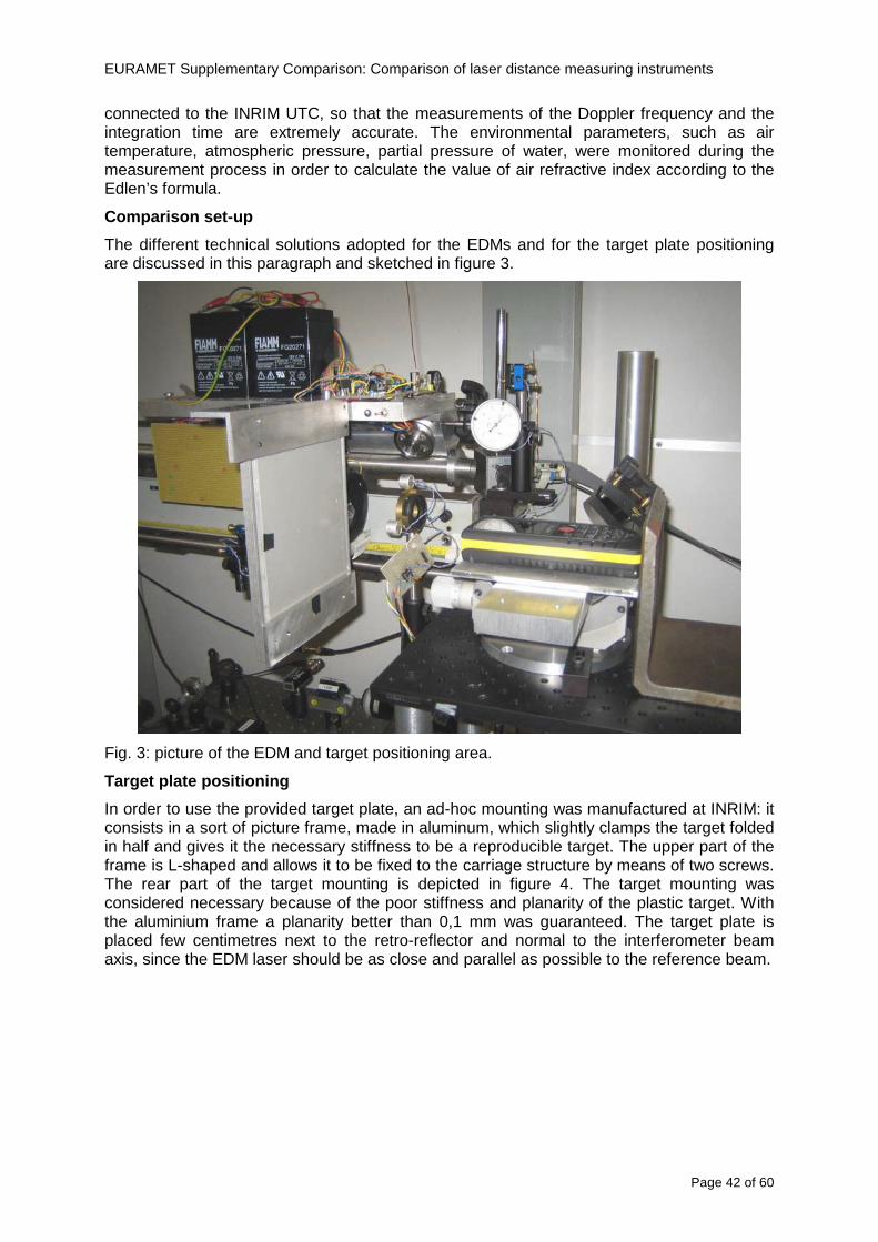
EURAMET Supplementary Comparison Comparison of laser distance measuring instruments
Page 42 of 60
connected to the INRIM UTC so that the measurements of the Doppler frequency and the integration time are extremely accurate The environmental parameters such as air temperature atmospheric pressure partial pressure of water were monitored during the measurement process in order to calculate the value of air refractive index according to the Edlenrsquos formula
Comparison set-up
The different technical solutions adopted for the EDMs and for the target plate positioning are discussed in this paragraph and sketched in figure 3
Fig 3 picture of the EDM and target positioning area
Target plate positioning
In order to use the provided target plate an ad-hoc mounting was manufactured at INRIM it consists in a sort of picture frame made in aluminum which slightly clamps the target folded in half and gives it the necessary stiffness to be a reproducible target The upper part of the frame is L-shaped and allows it to be fixed to the carriage structure by means of two screws The rear part of the target mounting is depicted in figure 4 The target mounting was considered necessary because of the poor stiffness and planarity of the plastic target With the aluminium frame a planarity better than 01 mm was guaranteed The target plate is placed few centimetres next to the retro-reflector and normal to the interferometer beam axis since the EDM laser should be as close and parallel as possible to the reference beam
EURAMET Supplementary Comparison Comparison of laser distance measuring instruments
Page 43 of 60
Fig 4 picture of the rear part of the target plate mounting
EDMsrsquo positioning
The EDMs are placed on a cradle-like platform which is able to adjust the inclination of the EDM along the longitudinal axis (pitch angle) The platform height allows the EDMs to be at approx the same height as the interferometer beam A crucial role was played by the stop-wall placed behind the platform since it represents the ldquozero pointrdquo for all the length measurement Hence a particular effort was devoted to align the stop-wall so that it was normal to the interferometer beam axis and parallel to the target plate
Fig 5 detail of EDMsrsquo positioning the cradle-like platform and the stop-wall are well visible
EURAMET Supplementary Comparison Comparison of laser distance measuring instruments
Page 44 of 60
Target and stop-wall alignment
In order to have the stop-wall parallel to the target plate and normal to the interferometer beam axis the following procedure has been used
1) the stop-wall and the target plate were roughly placed trying to set them parallel and normal to the rail by eye (ie within few millimeters)
2) in order to check if the target was normal to the rail one EDM was positioned on the platform the pitch and yaw angles of the EDM were adjusted by observing the position of the EDM laser spot on the target plate when the target is moved along the rail fixed position means laser beam parallel to the carriage movement Then the target was moved until the end of the rail and a thin mirror was kept in contact with it hence observing the EDM laser reflected by the mirror it was possible to adjust the target tilt acting on the screws until the laser beam is reflected back to the source
3) finally in order to check the parallelism between the stop-wall and the target a tool made by a laser pointing orthogonally to its base was used the base was leant against the stop-wall and the laser was centered on the target when the target is near then the target was moved until the end of the rail hence observing the spot of the laser on the target it was possible to adjust the stop-wall orientation
The residual misalignment errors which we were not able to eliminate were kept into account in the uncertainty budget
Measurement of the first 30 cm
Due to the geometry of our set-up it was not possible to perform the first point of measurement by means of the interferometer indeed the carriage (hence the target) is not able to go in contact with the stop-wall
Fig 6 measurement of the first 30 cm the ruler touching the stop-wall and the target and the mechanical probe (in the back) touching the carriage are visible
EURAMET Supplementary Comparison Comparison of laser distance measuring instruments
Page 45 of 60
So a ruler made of aluminum with rounded ends and nominal length equal to 30 cm was adopted to set the distance between the target plate and the stop-wall for the first point of measurement as it is shown in figure 6 The ruler whose length was measured by a CMM machine was inserted between the target and the stop-wall leaning against the latter and the carriage was carefully moved towards the stop-wall until the target lightly touched the ruler A mechanical probe that touches the carriage structure when carriage is in the ldquo30 cmrdquo position was used as a reference measurement to check the repeatability of this distance after each measurement set
Fig 7 detail of the mechanical probe touching the carriage
Environmental parameters
The environmental parameters such as air temperature atmospheric pressure and humidity were monitored during the whole measurement process in order to calculate the value of air refractive index according to the Edlenrsquos formula
Among these parameters the temperature distribution along the mobile arm of the interferometer was our main concern mainly for two reasons
1 the temperature control of the gallery was not perfectly working during the measurement period so temperature drifts had to be monitored
2 longitudinal temperature gradients due to non uniform heating and to the presence of electronic instruments were pretty high
To the purpose 14 thermometers were uniformly dislocated along the rail and automatically recorded for all the measurement period Both temporal drifts and gradients along the path have been taken in account in the uncertainty budget In any case maximum temperature differences along the rail are within 1 degC In fig 8 an extract from the acquisition file is shown
Unfortunately the air conditioning system did not work well during the measurement campaign hence the measurements were performed at a mean temperature of 209 degC
EURAMET Supplementary Comparison Comparison of laser distance measuring instruments
Page 46 of 60
Fig 8 each curve represents the temperature distribution along the rail during the measurements campaign
Carriage waving
Since the rail is not perfectly straight and the measurement laser is not coincident with the measurement beam the Abbegrave error due to waving of the target must be considered A quantitative measurement and a qualitative measurement were carried out With an electronic level placed on the carriage the straightness on the vertical plane has been mapped with a half meter resolution (the data are reported in fig 9) With a laser placed on the carriage the horizontal and vertical waving are qualitatively compared by looking at the movements of the light spot on a target fixed to the rail end As a conclusion the horizontal and vertical waving are comparable in magnitude and the peak to peak error is of the order of 300 arcseconds
Fig 9 vertical waving of the target measured by an electronic level placed on the carriage
EURAMET Supplementary Comparison Comparison of laser distance measuring instruments
Page 47 of 60
Measurement procedure
The measurements were carried out according to the following procedure
The target was set in the starting position with the procedure described above
In sequence the four EDMs are positioned on the base the horizontal and vertical tilt are adjusted and the distance measurement is recorded An additional fifth EDM (Bosh DLE 150 property of INRiM) was included in the measurement sequence Each EDM is placed on the base and gently pushed against the reference wall in such a way that the measurement laser beam starting point is the same for all EDMs Than the horizontal and vertical angles were adjusted in order to hit the central point of the target indicated with two black marks (see pictures 3 and 6) with ldquovisualrdquo alignment The measurement button is then pressed several times (typically 5) and the average reading is recorded Typical dispersion between readings is within few last digit units In case the dispersion between readings is too large the anomaly is recorded
The carriage was then moved in the next position (about 5 m) and the measurement sequence was repeated for the 5 EDMs The operation is repeated up to 25 m The 25 m measurement is than repeated again as well as all the points till the first one so that each point is measured twice each set Since the carriage movement is ldquoopen looprdquo the positioning of the carriage was not exactly in the nominal 5 m intervals For each positioning the incremental displacement is measured by the interferometer in the Doppler mode Finally the measured values were averaged in order to give a single value for each nominal position
At the end of the measurement set when the carriage is at the 30 cm position again the sum of the interferometric measurements should be very close to zero The residual value is compared with the difference between the first and the final measurements of the mechanical probe The difference must be within the uncertainty of the Doppler technique otherwise some error occurred in the measurement set that must be repeated
At the end of the session 10 complete sets of measurements recorded from the 20th to the 30th of January 2012 have been considered for this report
Additional remarks
Effect of laser pointing
During a preliminary set of measurements we noticed a strong and unexpected dependence of the measurement result on the position of the laser spot on the target Indeed since no particular instructions were given about the relative position of the laser spot on target position (except to exclude the central joint between the two halves) we decided to work relatively close to the right side of the target -closer to the interferometer beam- in order to reduce the Abbegrave error We noticed very large errors at large distances in particular of the Leica DISTO D3a (see figure 10)
EURAMET Supplementary Comparison Comparison of laser distance measuring instruments
Page 48 of 60
Fig 10 errors of each EDM In a preliminary set of measurements
We also noticed that this error was strongly dependent on the position of the spot on the target For this reason we carried out a set of measurements at the maximum length in different positions of the target from one edge to the other according to figure 11 The results are reported in table V
EDM A B C D E
Leica D3a -4 +1 0 +24 +43
+2 0 +42 +40
-1 0 +38
Leica D8 0 0 0 2 +7
0 +12 +23
table V deviations (in mm) from the length measured at point C aiming the laser spot at different positions of the target (notations as in figure 11)
We tried to find an explanation to this effect in the shape of the laser spot if the spot was
EURAMET Supplementary Comparison Comparison of laser distance measuring instruments
Page 49 of 60
particularly defocused or had high diffraction some of the energy could fall out of the target and affect the measurement result In fact the images of the spots (shown in fig 12) do not support this hypothesis Finally we decided to use the center of the (half) target for the comparison
Changing the target
In order to investigate the influence of the target on the measurements a cardboard foil (400 x 400) mm was fixed to the target mounting and a complete set of measurements was performed The results reported in figure 13 and 14 do not show any evidence of a possible dependency of the EDM measurement on the target kind
EURAMET Supplementary Comparison Comparison of laser distance measuring instruments
Page 50 of 60
Measurement at 50 m
Although we are not able to perform traceable length measurements beyond 28 m we wanted to get a sense of EDMs behaviour at longer distances So a target (represented by a rack side wall) was placed at approximately 50 m one after the other the EDMrsquos were positioned on the base and pointed towards the target The measurements were repeated then the target was replaced by the target used for the comparison and a third set of measurements were performed To our great surprise all the EDMrsquos were in good agreement (within 2 or 3 mm for each set of measurement) even those which showed errors of the order of five to ten millimeters at 25 m namely BOSCH DLE 50 and LEICA DISTO D3a Therefore each set of measurements was averaged and the deviations from the mean value are reported in figure 15
EURAMET Supplementary Comparison Comparison of laser distance measuring instruments
Page 51 of 60
Fig 15 Deviations from average value of the measurements At 50 m
EURAMET Supplementary Comparison Comparison of laser distance measuring instruments
Page 52 of 60
A19 CEM Spain
Short description of the measurement bench
To make the measurements of EDMs we have used a reference line made of adjustable supports fixed on a wall of the laboratory Each support is nominally separated five metres from the previous one so we can generate reference lengths up to fifty metres with a pitch of five metres The supports are designed to accommodate both targets and handheld EDMs Distances between supports were measured by using a total station traced to national standards The relative angles of the bases have been measured and corrected
Fig 1 - View of three consecutive supports of the 50 m baseline (left) Lab technician situating an EDM on the first support of the baseline (right)
Length measurement instrument
The baseline was calibrated by using a total station Leica TDA5005 with spherical reflector the calibration uncertainty being 02 mm for k = 2
The target is provided by the comparison The quality of the target was judged as not good due to geometrical constructive errors and the lack of rigidity and stability We measured the flatness of the target surface the distance edge-surface and the angle between them by using a 3D coordinate measuring machine The results of flatness and angle were included in the uncertainty budget and the distance EDM-target was corrected for each EDM due to each beam impinged on a different point of the target
We were not able to measure the distance 0 to 03 m because the baseline pitch is 5 meters and although we are able to measure shorter values in a different facility the target was not appropriate for our bench
EURAMET Supplementary Comparison Comparison of laser distance measuring instruments
Page 53 of 60
Fig 2 - View of an EDM on the first support of the baseline (left) A closer look showing the support adjustments and the origin plate (right)
Fig 3 - View of the comparison target on one of the supports of the baseline (left) A closer look showing the target edge against the support rigid reference (right)
Measurement method
The measurements were carried out by comparison against the known values of the calibrated baseline (metallic references on supports)
Environmental conditions were maintained within the following limits
- Temperature 20 ordmC plusmn 05 ordmC
- Humidity 45 plusmn 10
Each laser distance measuring instrument was placed at the first support of the base and aligned so that the laser beam was perpendicular to the target as indicated by the comparison protocol
For each measurement we took the average of thirty measurements It permitted us to evaluate the repeatability of the instrument
EURAMET Supplementary Comparison Comparison of laser distance measuring instruments
Page 54 of 60
A110 BEV Austria
Short description of the measurement bench
Fig 1 Carriage of tape bench View from the laser interferometer side Retroreflector mounted on the vertical plate the EDM target is mounted on the backside
Fig 2 Support for the DUT Adjustable with 2 translational and 2 rotational degrees of freedom respectively
Fig 3 Setting of the 300 mm starting position Note the rough-and-ready mounted target plate
Fig 4 Laser interferometer side of the bench The DUT is 50 m away on the other side
EURAMET Supplementary Comparison Comparison of laser distance measuring instruments
Page 55 of 60
Measurement procedure 1 The EDM is positioned with the help of a 4-axis positioning stage so that its laser beam is
coaxial with the measurement direction of the laser interferometer (in head on configuration)
2 The EDM is removed from its support The bench carriage is positioned so that the distance of the target plate from the EDM back support is 300 mm A length bar with spherical faces is used for this adjustment The laser interferometer is preset to 300 mm and the EDM is put back on its support
3 At each position 10 consecutive measurements are taken (repeatability) and the carriage is moved to the next position The carriage is manually moved under control of the laser interferometer until it is within plusmn30 microm at the correct position (Exception for the DLE 150 the target is not positioned at 10 m but at 10 m ndash 1 mm to make use of the higher resolution) The indicated (not the nominal) distance of the laser interferometer is recorded for the determination of the deviation
4 After reaching the 50 m position all points are measured in reverse order (bidirectional) Immediately after the last measurement the EDM is removed and the indication using the 300 mm length bar is checked (thus noting a possible drift of the setup)
5 Each instrument was measured 4 times according to this procedure on different days (reproducibility of bench and instrument)
Length measurement instrument
Agilent laser interferometer with long range option The bench was completed short time before performing these measurement So the characterisation was not complete and the respective measurement uncertainty of the laser interferometer is estimated rather high But anyway its contribution to the overall uncertainty can nearly be neglected
Additional remarks
The uncertainty originating from the DUT is the dominating uncertainty contribution Specifically the resolution of the two Bosch instruments (1 mm) and the repeatability are the largest contributions For the DLA 50 the pooled standard deviation of a reading at 50 m is larger than 2 mm Moreover the length dependence is not a simple function
All of the instruments show a significant deviation of the laser beam from the normal of the back (reference) face of the instrument The measured angles reach from 04deg (D3a) to 11deg (DLE 50) This leads depending on the outer dimensions of the instruments to a constant uncertainty contribution of 02 mm in our setup It must be noted that the reference faces are not well defined in most of the instruments
The reproducibility is quite different for the four instruments so only part of it originates from the setup For CMC claims we will use the standard uncertainty value of the most reproducible instrument (D3a) which amounts to 013 mm For an ideal instrument with a resolution of 01 mm and perfect repeatability we would thus have a constant expanded uncertainty of 053 mm up to 50 m
EURAMET Supplementary Comparison Comparison of laser distance measuring instruments
Page 56 of 60
A111 JV Norway
Short description of measurement bench
EDM under calibration and the reference system are aligned along a 50 m measurement bench with rails to carry the linear movement of a target plate for the EDM and a corner cube reflector for the reference system The distance between parallel axis of EDM and axis of the reference system is 130 mm Abbe error due to angle errors for the movement is smaller than 01 mm and is corrected for at each measurement point At long lengths an aperture is used approximately midway between the target plate and the EDM to avoid interfering stray light to the EDM
Alignment procedure
1) Alignment of reference system to the movement of the carriage (rails)
2) Alignment of the EDM to the movement of the carriage (rails)
3) Alignment of a plane mirror at the position of the target plate using back-reflection to the EDM output (normal incident of light on the mirror)
4) Take out the EDM and align the zero reference plate at the back of the EDM to the plane mirror
5) The mirror is replaced by the target plate and the target plate is aligned to the zero reference plate
6) Zero setting of the reference measurement system when target plate is at zero distance to the reference plate at the back of the EDM
7) Put the EDM back in position and realign it to the movement of the carriage (rails)
8) Zero setting of the EDM to the reference plate
Image 1) Image 2) Image 3) Image 4)
Image 1) Items 5) ndash 6) in alignment procedure
Fixture for HP linear interferometer is seen bottom right Part of Wyler instrument is seen to the left blue colour
Image 2) Items 7) and 8) in alignment procedure
Micrometer screws for angle alignment in two directions and linear translation for zero setting of the EDM Push button on the EDM is positioned at the tilting point of the angle adjustment table to maximize stability during measurement HP 5519 A laser head is seen to the right
Image 3) Ready to measure at selected distances from zero point the reference plate
Image 4) EDM spot size at 50 m
Length measurement instrument
- Hewlett Packard Dynamic Calibrator 5519 A (max range 80 m)
- Pressure air temperature humidity Vaisala
EURAMET Supplementary Comparison Comparison of laser distance measuring instruments
Page 57 of 60
- Digital high resolution angle measurement Wyler
I used our own target plate which is of the same type as enclosed in the artefact suitcase article number 766560 from Leica but with reduced size width x hight = 90 x 137 mm
The zero reference plate is of similar type and size
Before measurements batteries of EDMs were switched to new batteries Old batteries are switched back after calibration
For L gt 5 m an aperture of similar size as the target plate is used approximately midway between the EDM and the target plate
Additional remarks
Reports on EDM indicated values at each measurement point is the average value of n = 5 repetitions A linear model of the standard deviation for the repeatability of the EDM readings at different lengths is estimated using m = 20 repetitions at least 5 positions along the scale An estimate of the length dependent repeatability is made for each instrument
The expanded uncertainty U(95) is rounded up to the limiting resolution of 1 mm in the interval 10 m to 40 m for Bosch GLM 150
After the calibration we also estimated the angle error of the optical axis of the EDM to its back plane (back reference of EDM) Bosch DLE 50 26 mrad up measured at 50 m Bosch GLM 150 8 mrad to the left measured at 50 m Leica DISTO D3a 37 mrad down measured at 20 m Leica DISTO D8 2 mrad to the left and 4 mrad down (45 mrad total) measured at 20 m
The distance between parallel walls will be measured too large if the back plane is assumed to be normal to the optical axis of the EDM by ∆LL = (1cosα ndash 1) Bosch DLE 50 ∆LL = 340 ppm (∆L = 17 mm at L = 50 m) Bosch GLM 150 ∆LL = 32 ppm (∆L = 16 mm at L = 50 m) Leica DISTO D3a ∆LL = 7 ppm (∆L = 034 mm at L = 50 m) Leica DISTO D8 ∆LL = 10 ppm (∆L = 05 mm at L = 50 m)
EURAMET Supplementary Comparison Comparison of laser distance measuring instruments
Page 58 of 60
A112 METAS Switzerland
Short description of measurement bench (photo recom mended)
50 m bench with laser interferometer (see photo detailed description in Michel Degoumois Un Long laboratoire de mesure OFMETinfo Vol5 No 2 1998)
Length measurement instrument
HP 5529 B laser interferometer range 80 m
EURAMET Supplementary Comparison Comparison of laser distance measuring instruments
Page 59 of 60
A113 GUM Poland
Short description of measurement bench
The 50 m bench is situated in the corridor laboratory located in the basement and has its own air conditioning system with air temperature 20 plusmn 1 degC and humidity 50 plusmn 10 RH The measuring carriage is carried microscope with CCD camera and the optics associated with the interferometer The carriage is driven using belt-transmission and electrical engine with remote ndash controlled variable speed drive
The EDM was placed on the fixed adjustable plate on the other end than laser interferometer The target plate of the EDM was placed on the measuring carriage For each EDM 3 series of measurement were done Before the each measurement EDM was repositioned and aligned again
Length measurement instrument
1 Laser interferometer HP 5529A with long-range option laser head HP 5519A
2 Ambient measurement system number and location of sensors - 20 air temperature sensors type YSI with KEITHLEY multimeter they are placed very
close to axis of the laser beam - air pressure and humidity are measured with Vaisala barometer and
thermohigrometer - CO2 content was measured with analyzer made by Intelli Charge type SPN 4462
EURAMET Supplementary Comparison Comparison of laser distance measuring instruments
Page 60 of 60
Appendix 2 Corrections of reports
131 CEM Spain
CEM reported two errors in their report
1) Bosch GLM 150 EDM error for 35 m should be -08 mm instead of the indicated 08 mm
2) Leica DISTO D8 EDM error for 35 m should be -019 mm instead of the indicated 019 mm
Proposed corrections have been included in Tables 2 and 4 of the Final Report
132 AS Metrosert Estonia
AS Metrosert reported mixed up of all results for Bosch DLE 50 and Bosch GLM 150 The results and uncertainties sent for DLE 50 was results for GLM 150 and vice versa
Proposed corrections have been included in Tables 1 and 2 of the Final Report
133 INRIM Italy
Among the data reported from INRIM some anomalies were found in the measurements of BOSCH DLE 50 and LEICA DISTO D3a at distances of 20 and 25 m
After preliminary discussion on Draft A it was understood that those anomalies could be explained as a sensitivity of said instruments to the laser light that once diffused by the target is reflected by surfaces parallel to the measurement axis and detected together with the wanted signal The superimposition of the two signals can cause a ldquopullingrdquo effect leading to an overestimation of the distance being the reflected path always longer than the direct one Indeed in the INRIMrsquos set-up the target was mounted pretty close to the flat rail used for the carriage movement being likely responsible for unwanted reflections that disturbed the measurements
Since the errors reported in INRIMrsquos measurements can be ascribed to a defect of BOSCH DLE 50 and LEICA DISTO D3a andor to a lack of description of the working conditions of said instruments INRIM asked to eliminate its measurement points at 20 and 25 m of said instruments from the comparison
Proposed corrections have been included in Tables 1 and 3 of the Final Report
134 JV Norway
Justervesenet has changed the procedure and introduced two apertures instead of only one aperture (iris) which was positioned at half distance between EDM and target The reason is that the reference beam also has an aperture and it is positioned right below the beam from the EDM (130 mm distance between axes) Some diffusively reflected stray light from the EDM target might enter the aperture for the reference beam reflect at the measurement table and reach the detector of the EDM In our calibration set-up we have only seen problems at L gt 30 m We will position the first aperture at ca 5 m from the EDM and then the second aperture at ca 25 m This combination of two apertures will effectively eliminate interference of stray light from the measurement table to the EDM detector for all lengths up to 50 m
Justervesenet also increases the uncertainty component regarding repeatability reproducibility so that the expanded uncertainty increases from 14 mm to 15 mm
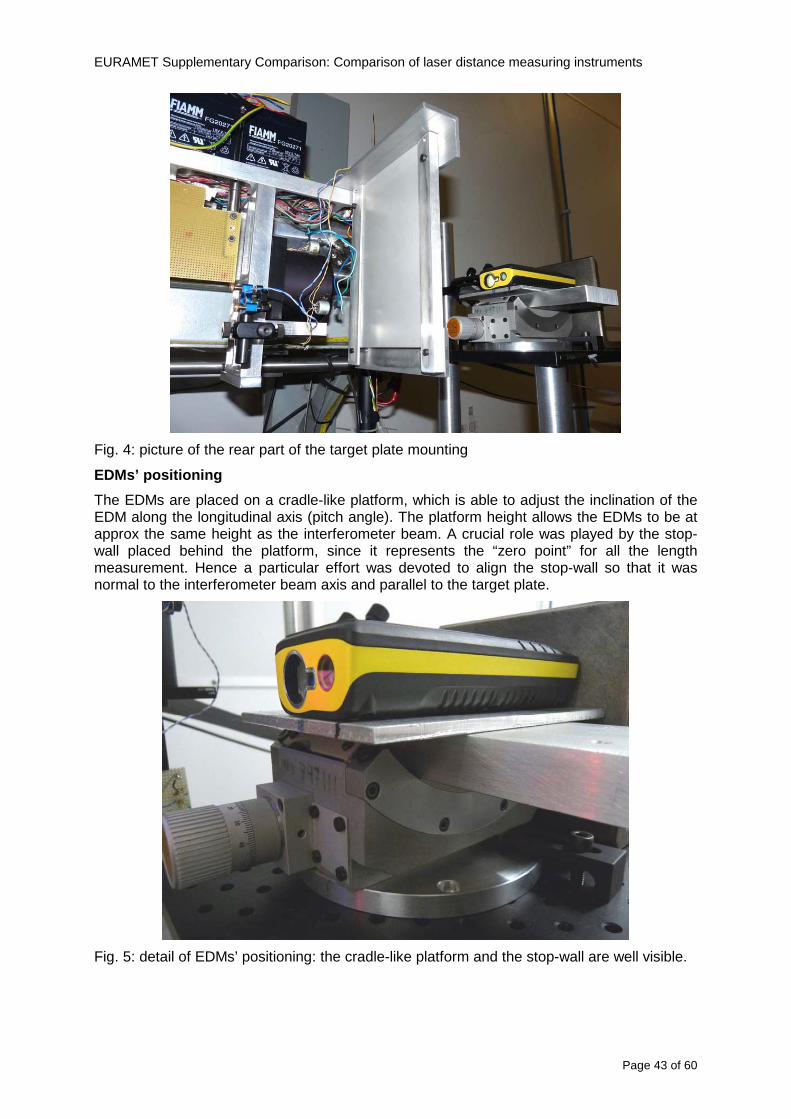
EURAMET Supplementary Comparison Comparison of laser distance measuring instruments
Page 43 of 60
Fig 4 picture of the rear part of the target plate mounting
EDMsrsquo positioning
The EDMs are placed on a cradle-like platform which is able to adjust the inclination of the EDM along the longitudinal axis (pitch angle) The platform height allows the EDMs to be at approx the same height as the interferometer beam A crucial role was played by the stop-wall placed behind the platform since it represents the ldquozero pointrdquo for all the length measurement Hence a particular effort was devoted to align the stop-wall so that it was normal to the interferometer beam axis and parallel to the target plate
Fig 5 detail of EDMsrsquo positioning the cradle-like platform and the stop-wall are well visible
EURAMET Supplementary Comparison Comparison of laser distance measuring instruments
Page 44 of 60
Target and stop-wall alignment
In order to have the stop-wall parallel to the target plate and normal to the interferometer beam axis the following procedure has been used
1) the stop-wall and the target plate were roughly placed trying to set them parallel and normal to the rail by eye (ie within few millimeters)
2) in order to check if the target was normal to the rail one EDM was positioned on the platform the pitch and yaw angles of the EDM were adjusted by observing the position of the EDM laser spot on the target plate when the target is moved along the rail fixed position means laser beam parallel to the carriage movement Then the target was moved until the end of the rail and a thin mirror was kept in contact with it hence observing the EDM laser reflected by the mirror it was possible to adjust the target tilt acting on the screws until the laser beam is reflected back to the source
3) finally in order to check the parallelism between the stop-wall and the target a tool made by a laser pointing orthogonally to its base was used the base was leant against the stop-wall and the laser was centered on the target when the target is near then the target was moved until the end of the rail hence observing the spot of the laser on the target it was possible to adjust the stop-wall orientation
The residual misalignment errors which we were not able to eliminate were kept into account in the uncertainty budget
Measurement of the first 30 cm
Due to the geometry of our set-up it was not possible to perform the first point of measurement by means of the interferometer indeed the carriage (hence the target) is not able to go in contact with the stop-wall
Fig 6 measurement of the first 30 cm the ruler touching the stop-wall and the target and the mechanical probe (in the back) touching the carriage are visible
EURAMET Supplementary Comparison Comparison of laser distance measuring instruments
Page 45 of 60
So a ruler made of aluminum with rounded ends and nominal length equal to 30 cm was adopted to set the distance between the target plate and the stop-wall for the first point of measurement as it is shown in figure 6 The ruler whose length was measured by a CMM machine was inserted between the target and the stop-wall leaning against the latter and the carriage was carefully moved towards the stop-wall until the target lightly touched the ruler A mechanical probe that touches the carriage structure when carriage is in the ldquo30 cmrdquo position was used as a reference measurement to check the repeatability of this distance after each measurement set
Fig 7 detail of the mechanical probe touching the carriage
Environmental parameters
The environmental parameters such as air temperature atmospheric pressure and humidity were monitored during the whole measurement process in order to calculate the value of air refractive index according to the Edlenrsquos formula
Among these parameters the temperature distribution along the mobile arm of the interferometer was our main concern mainly for two reasons
1 the temperature control of the gallery was not perfectly working during the measurement period so temperature drifts had to be monitored
2 longitudinal temperature gradients due to non uniform heating and to the presence of electronic instruments were pretty high
To the purpose 14 thermometers were uniformly dislocated along the rail and automatically recorded for all the measurement period Both temporal drifts and gradients along the path have been taken in account in the uncertainty budget In any case maximum temperature differences along the rail are within 1 degC In fig 8 an extract from the acquisition file is shown
Unfortunately the air conditioning system did not work well during the measurement campaign hence the measurements were performed at a mean temperature of 209 degC
EURAMET Supplementary Comparison Comparison of laser distance measuring instruments
Page 46 of 60
Fig 8 each curve represents the temperature distribution along the rail during the measurements campaign
Carriage waving
Since the rail is not perfectly straight and the measurement laser is not coincident with the measurement beam the Abbegrave error due to waving of the target must be considered A quantitative measurement and a qualitative measurement were carried out With an electronic level placed on the carriage the straightness on the vertical plane has been mapped with a half meter resolution (the data are reported in fig 9) With a laser placed on the carriage the horizontal and vertical waving are qualitatively compared by looking at the movements of the light spot on a target fixed to the rail end As a conclusion the horizontal and vertical waving are comparable in magnitude and the peak to peak error is of the order of 300 arcseconds
Fig 9 vertical waving of the target measured by an electronic level placed on the carriage
EURAMET Supplementary Comparison Comparison of laser distance measuring instruments
Page 47 of 60
Measurement procedure
The measurements were carried out according to the following procedure
The target was set in the starting position with the procedure described above
In sequence the four EDMs are positioned on the base the horizontal and vertical tilt are adjusted and the distance measurement is recorded An additional fifth EDM (Bosh DLE 150 property of INRiM) was included in the measurement sequence Each EDM is placed on the base and gently pushed against the reference wall in such a way that the measurement laser beam starting point is the same for all EDMs Than the horizontal and vertical angles were adjusted in order to hit the central point of the target indicated with two black marks (see pictures 3 and 6) with ldquovisualrdquo alignment The measurement button is then pressed several times (typically 5) and the average reading is recorded Typical dispersion between readings is within few last digit units In case the dispersion between readings is too large the anomaly is recorded
The carriage was then moved in the next position (about 5 m) and the measurement sequence was repeated for the 5 EDMs The operation is repeated up to 25 m The 25 m measurement is than repeated again as well as all the points till the first one so that each point is measured twice each set Since the carriage movement is ldquoopen looprdquo the positioning of the carriage was not exactly in the nominal 5 m intervals For each positioning the incremental displacement is measured by the interferometer in the Doppler mode Finally the measured values were averaged in order to give a single value for each nominal position
At the end of the measurement set when the carriage is at the 30 cm position again the sum of the interferometric measurements should be very close to zero The residual value is compared with the difference between the first and the final measurements of the mechanical probe The difference must be within the uncertainty of the Doppler technique otherwise some error occurred in the measurement set that must be repeated
At the end of the session 10 complete sets of measurements recorded from the 20th to the 30th of January 2012 have been considered for this report
Additional remarks
Effect of laser pointing
During a preliminary set of measurements we noticed a strong and unexpected dependence of the measurement result on the position of the laser spot on the target Indeed since no particular instructions were given about the relative position of the laser spot on target position (except to exclude the central joint between the two halves) we decided to work relatively close to the right side of the target -closer to the interferometer beam- in order to reduce the Abbegrave error We noticed very large errors at large distances in particular of the Leica DISTO D3a (see figure 10)
EURAMET Supplementary Comparison Comparison of laser distance measuring instruments
Page 48 of 60
Fig 10 errors of each EDM In a preliminary set of measurements
We also noticed that this error was strongly dependent on the position of the spot on the target For this reason we carried out a set of measurements at the maximum length in different positions of the target from one edge to the other according to figure 11 The results are reported in table V
EDM A B C D E
Leica D3a -4 +1 0 +24 +43
+2 0 +42 +40
-1 0 +38
Leica D8 0 0 0 2 +7
0 +12 +23
table V deviations (in mm) from the length measured at point C aiming the laser spot at different positions of the target (notations as in figure 11)
We tried to find an explanation to this effect in the shape of the laser spot if the spot was
EURAMET Supplementary Comparison Comparison of laser distance measuring instruments
Page 49 of 60
particularly defocused or had high diffraction some of the energy could fall out of the target and affect the measurement result In fact the images of the spots (shown in fig 12) do not support this hypothesis Finally we decided to use the center of the (half) target for the comparison
Changing the target
In order to investigate the influence of the target on the measurements a cardboard foil (400 x 400) mm was fixed to the target mounting and a complete set of measurements was performed The results reported in figure 13 and 14 do not show any evidence of a possible dependency of the EDM measurement on the target kind
EURAMET Supplementary Comparison Comparison of laser distance measuring instruments
Page 50 of 60
Measurement at 50 m
Although we are not able to perform traceable length measurements beyond 28 m we wanted to get a sense of EDMs behaviour at longer distances So a target (represented by a rack side wall) was placed at approximately 50 m one after the other the EDMrsquos were positioned on the base and pointed towards the target The measurements were repeated then the target was replaced by the target used for the comparison and a third set of measurements were performed To our great surprise all the EDMrsquos were in good agreement (within 2 or 3 mm for each set of measurement) even those which showed errors of the order of five to ten millimeters at 25 m namely BOSCH DLE 50 and LEICA DISTO D3a Therefore each set of measurements was averaged and the deviations from the mean value are reported in figure 15
EURAMET Supplementary Comparison Comparison of laser distance measuring instruments
Page 51 of 60
Fig 15 Deviations from average value of the measurements At 50 m
EURAMET Supplementary Comparison Comparison of laser distance measuring instruments
Page 52 of 60
A19 CEM Spain
Short description of the measurement bench
To make the measurements of EDMs we have used a reference line made of adjustable supports fixed on a wall of the laboratory Each support is nominally separated five metres from the previous one so we can generate reference lengths up to fifty metres with a pitch of five metres The supports are designed to accommodate both targets and handheld EDMs Distances between supports were measured by using a total station traced to national standards The relative angles of the bases have been measured and corrected
Fig 1 - View of three consecutive supports of the 50 m baseline (left) Lab technician situating an EDM on the first support of the baseline (right)
Length measurement instrument
The baseline was calibrated by using a total station Leica TDA5005 with spherical reflector the calibration uncertainty being 02 mm for k = 2
The target is provided by the comparison The quality of the target was judged as not good due to geometrical constructive errors and the lack of rigidity and stability We measured the flatness of the target surface the distance edge-surface and the angle between them by using a 3D coordinate measuring machine The results of flatness and angle were included in the uncertainty budget and the distance EDM-target was corrected for each EDM due to each beam impinged on a different point of the target
We were not able to measure the distance 0 to 03 m because the baseline pitch is 5 meters and although we are able to measure shorter values in a different facility the target was not appropriate for our bench
EURAMET Supplementary Comparison Comparison of laser distance measuring instruments
Page 53 of 60
Fig 2 - View of an EDM on the first support of the baseline (left) A closer look showing the support adjustments and the origin plate (right)
Fig 3 - View of the comparison target on one of the supports of the baseline (left) A closer look showing the target edge against the support rigid reference (right)
Measurement method
The measurements were carried out by comparison against the known values of the calibrated baseline (metallic references on supports)
Environmental conditions were maintained within the following limits
- Temperature 20 ordmC plusmn 05 ordmC
- Humidity 45 plusmn 10
Each laser distance measuring instrument was placed at the first support of the base and aligned so that the laser beam was perpendicular to the target as indicated by the comparison protocol
For each measurement we took the average of thirty measurements It permitted us to evaluate the repeatability of the instrument
EURAMET Supplementary Comparison Comparison of laser distance measuring instruments
Page 54 of 60
A110 BEV Austria
Short description of the measurement bench
Fig 1 Carriage of tape bench View from the laser interferometer side Retroreflector mounted on the vertical plate the EDM target is mounted on the backside
Fig 2 Support for the DUT Adjustable with 2 translational and 2 rotational degrees of freedom respectively
Fig 3 Setting of the 300 mm starting position Note the rough-and-ready mounted target plate
Fig 4 Laser interferometer side of the bench The DUT is 50 m away on the other side
EURAMET Supplementary Comparison Comparison of laser distance measuring instruments
Page 55 of 60
Measurement procedure 1 The EDM is positioned with the help of a 4-axis positioning stage so that its laser beam is
coaxial with the measurement direction of the laser interferometer (in head on configuration)
2 The EDM is removed from its support The bench carriage is positioned so that the distance of the target plate from the EDM back support is 300 mm A length bar with spherical faces is used for this adjustment The laser interferometer is preset to 300 mm and the EDM is put back on its support
3 At each position 10 consecutive measurements are taken (repeatability) and the carriage is moved to the next position The carriage is manually moved under control of the laser interferometer until it is within plusmn30 microm at the correct position (Exception for the DLE 150 the target is not positioned at 10 m but at 10 m ndash 1 mm to make use of the higher resolution) The indicated (not the nominal) distance of the laser interferometer is recorded for the determination of the deviation
4 After reaching the 50 m position all points are measured in reverse order (bidirectional) Immediately after the last measurement the EDM is removed and the indication using the 300 mm length bar is checked (thus noting a possible drift of the setup)
5 Each instrument was measured 4 times according to this procedure on different days (reproducibility of bench and instrument)
Length measurement instrument
Agilent laser interferometer with long range option The bench was completed short time before performing these measurement So the characterisation was not complete and the respective measurement uncertainty of the laser interferometer is estimated rather high But anyway its contribution to the overall uncertainty can nearly be neglected
Additional remarks
The uncertainty originating from the DUT is the dominating uncertainty contribution Specifically the resolution of the two Bosch instruments (1 mm) and the repeatability are the largest contributions For the DLA 50 the pooled standard deviation of a reading at 50 m is larger than 2 mm Moreover the length dependence is not a simple function
All of the instruments show a significant deviation of the laser beam from the normal of the back (reference) face of the instrument The measured angles reach from 04deg (D3a) to 11deg (DLE 50) This leads depending on the outer dimensions of the instruments to a constant uncertainty contribution of 02 mm in our setup It must be noted that the reference faces are not well defined in most of the instruments
The reproducibility is quite different for the four instruments so only part of it originates from the setup For CMC claims we will use the standard uncertainty value of the most reproducible instrument (D3a) which amounts to 013 mm For an ideal instrument with a resolution of 01 mm and perfect repeatability we would thus have a constant expanded uncertainty of 053 mm up to 50 m
EURAMET Supplementary Comparison Comparison of laser distance measuring instruments
Page 56 of 60
A111 JV Norway
Short description of measurement bench
EDM under calibration and the reference system are aligned along a 50 m measurement bench with rails to carry the linear movement of a target plate for the EDM and a corner cube reflector for the reference system The distance between parallel axis of EDM and axis of the reference system is 130 mm Abbe error due to angle errors for the movement is smaller than 01 mm and is corrected for at each measurement point At long lengths an aperture is used approximately midway between the target plate and the EDM to avoid interfering stray light to the EDM
Alignment procedure
1) Alignment of reference system to the movement of the carriage (rails)
2) Alignment of the EDM to the movement of the carriage (rails)
3) Alignment of a plane mirror at the position of the target plate using back-reflection to the EDM output (normal incident of light on the mirror)
4) Take out the EDM and align the zero reference plate at the back of the EDM to the plane mirror
5) The mirror is replaced by the target plate and the target plate is aligned to the zero reference plate
6) Zero setting of the reference measurement system when target plate is at zero distance to the reference plate at the back of the EDM
7) Put the EDM back in position and realign it to the movement of the carriage (rails)
8) Zero setting of the EDM to the reference plate
Image 1) Image 2) Image 3) Image 4)
Image 1) Items 5) ndash 6) in alignment procedure
Fixture for HP linear interferometer is seen bottom right Part of Wyler instrument is seen to the left blue colour
Image 2) Items 7) and 8) in alignment procedure
Micrometer screws for angle alignment in two directions and linear translation for zero setting of the EDM Push button on the EDM is positioned at the tilting point of the angle adjustment table to maximize stability during measurement HP 5519 A laser head is seen to the right
Image 3) Ready to measure at selected distances from zero point the reference plate
Image 4) EDM spot size at 50 m
Length measurement instrument
- Hewlett Packard Dynamic Calibrator 5519 A (max range 80 m)
- Pressure air temperature humidity Vaisala
EURAMET Supplementary Comparison Comparison of laser distance measuring instruments
Page 57 of 60
- Digital high resolution angle measurement Wyler
I used our own target plate which is of the same type as enclosed in the artefact suitcase article number 766560 from Leica but with reduced size width x hight = 90 x 137 mm
The zero reference plate is of similar type and size
Before measurements batteries of EDMs were switched to new batteries Old batteries are switched back after calibration
For L gt 5 m an aperture of similar size as the target plate is used approximately midway between the EDM and the target plate
Additional remarks
Reports on EDM indicated values at each measurement point is the average value of n = 5 repetitions A linear model of the standard deviation for the repeatability of the EDM readings at different lengths is estimated using m = 20 repetitions at least 5 positions along the scale An estimate of the length dependent repeatability is made for each instrument
The expanded uncertainty U(95) is rounded up to the limiting resolution of 1 mm in the interval 10 m to 40 m for Bosch GLM 150
After the calibration we also estimated the angle error of the optical axis of the EDM to its back plane (back reference of EDM) Bosch DLE 50 26 mrad up measured at 50 m Bosch GLM 150 8 mrad to the left measured at 50 m Leica DISTO D3a 37 mrad down measured at 20 m Leica DISTO D8 2 mrad to the left and 4 mrad down (45 mrad total) measured at 20 m
The distance between parallel walls will be measured too large if the back plane is assumed to be normal to the optical axis of the EDM by ∆LL = (1cosα ndash 1) Bosch DLE 50 ∆LL = 340 ppm (∆L = 17 mm at L = 50 m) Bosch GLM 150 ∆LL = 32 ppm (∆L = 16 mm at L = 50 m) Leica DISTO D3a ∆LL = 7 ppm (∆L = 034 mm at L = 50 m) Leica DISTO D8 ∆LL = 10 ppm (∆L = 05 mm at L = 50 m)
EURAMET Supplementary Comparison Comparison of laser distance measuring instruments
Page 58 of 60
A112 METAS Switzerland
Short description of measurement bench (photo recom mended)
50 m bench with laser interferometer (see photo detailed description in Michel Degoumois Un Long laboratoire de mesure OFMETinfo Vol5 No 2 1998)
Length measurement instrument
HP 5529 B laser interferometer range 80 m
EURAMET Supplementary Comparison Comparison of laser distance measuring instruments
Page 59 of 60
A113 GUM Poland
Short description of measurement bench
The 50 m bench is situated in the corridor laboratory located in the basement and has its own air conditioning system with air temperature 20 plusmn 1 degC and humidity 50 plusmn 10 RH The measuring carriage is carried microscope with CCD camera and the optics associated with the interferometer The carriage is driven using belt-transmission and electrical engine with remote ndash controlled variable speed drive
The EDM was placed on the fixed adjustable plate on the other end than laser interferometer The target plate of the EDM was placed on the measuring carriage For each EDM 3 series of measurement were done Before the each measurement EDM was repositioned and aligned again
Length measurement instrument
1 Laser interferometer HP 5529A with long-range option laser head HP 5519A
2 Ambient measurement system number and location of sensors - 20 air temperature sensors type YSI with KEITHLEY multimeter they are placed very
close to axis of the laser beam - air pressure and humidity are measured with Vaisala barometer and
thermohigrometer - CO2 content was measured with analyzer made by Intelli Charge type SPN 4462
EURAMET Supplementary Comparison Comparison of laser distance measuring instruments
Page 60 of 60
Appendix 2 Corrections of reports
131 CEM Spain
CEM reported two errors in their report
1) Bosch GLM 150 EDM error for 35 m should be -08 mm instead of the indicated 08 mm
2) Leica DISTO D8 EDM error for 35 m should be -019 mm instead of the indicated 019 mm
Proposed corrections have been included in Tables 2 and 4 of the Final Report
132 AS Metrosert Estonia
AS Metrosert reported mixed up of all results for Bosch DLE 50 and Bosch GLM 150 The results and uncertainties sent for DLE 50 was results for GLM 150 and vice versa
Proposed corrections have been included in Tables 1 and 2 of the Final Report
133 INRIM Italy
Among the data reported from INRIM some anomalies were found in the measurements of BOSCH DLE 50 and LEICA DISTO D3a at distances of 20 and 25 m
After preliminary discussion on Draft A it was understood that those anomalies could be explained as a sensitivity of said instruments to the laser light that once diffused by the target is reflected by surfaces parallel to the measurement axis and detected together with the wanted signal The superimposition of the two signals can cause a ldquopullingrdquo effect leading to an overestimation of the distance being the reflected path always longer than the direct one Indeed in the INRIMrsquos set-up the target was mounted pretty close to the flat rail used for the carriage movement being likely responsible for unwanted reflections that disturbed the measurements
Since the errors reported in INRIMrsquos measurements can be ascribed to a defect of BOSCH DLE 50 and LEICA DISTO D3a andor to a lack of description of the working conditions of said instruments INRIM asked to eliminate its measurement points at 20 and 25 m of said instruments from the comparison
Proposed corrections have been included in Tables 1 and 3 of the Final Report
134 JV Norway
Justervesenet has changed the procedure and introduced two apertures instead of only one aperture (iris) which was positioned at half distance between EDM and target The reason is that the reference beam also has an aperture and it is positioned right below the beam from the EDM (130 mm distance between axes) Some diffusively reflected stray light from the EDM target might enter the aperture for the reference beam reflect at the measurement table and reach the detector of the EDM In our calibration set-up we have only seen problems at L gt 30 m We will position the first aperture at ca 5 m from the EDM and then the second aperture at ca 25 m This combination of two apertures will effectively eliminate interference of stray light from the measurement table to the EDM detector for all lengths up to 50 m
Justervesenet also increases the uncertainty component regarding repeatability reproducibility so that the expanded uncertainty increases from 14 mm to 15 mm
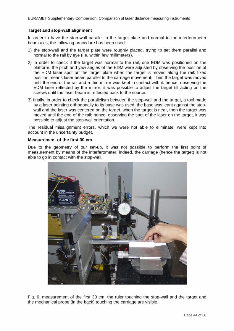
EURAMET Supplementary Comparison Comparison of laser distance measuring instruments
Page 44 of 60
Target and stop-wall alignment
In order to have the stop-wall parallel to the target plate and normal to the interferometer beam axis the following procedure has been used
1) the stop-wall and the target plate were roughly placed trying to set them parallel and normal to the rail by eye (ie within few millimeters)
2) in order to check if the target was normal to the rail one EDM was positioned on the platform the pitch and yaw angles of the EDM were adjusted by observing the position of the EDM laser spot on the target plate when the target is moved along the rail fixed position means laser beam parallel to the carriage movement Then the target was moved until the end of the rail and a thin mirror was kept in contact with it hence observing the EDM laser reflected by the mirror it was possible to adjust the target tilt acting on the screws until the laser beam is reflected back to the source
3) finally in order to check the parallelism between the stop-wall and the target a tool made by a laser pointing orthogonally to its base was used the base was leant against the stop-wall and the laser was centered on the target when the target is near then the target was moved until the end of the rail hence observing the spot of the laser on the target it was possible to adjust the stop-wall orientation
The residual misalignment errors which we were not able to eliminate were kept into account in the uncertainty budget
Measurement of the first 30 cm
Due to the geometry of our set-up it was not possible to perform the first point of measurement by means of the interferometer indeed the carriage (hence the target) is not able to go in contact with the stop-wall
Fig 6 measurement of the first 30 cm the ruler touching the stop-wall and the target and the mechanical probe (in the back) touching the carriage are visible
EURAMET Supplementary Comparison Comparison of laser distance measuring instruments
Page 45 of 60
So a ruler made of aluminum with rounded ends and nominal length equal to 30 cm was adopted to set the distance between the target plate and the stop-wall for the first point of measurement as it is shown in figure 6 The ruler whose length was measured by a CMM machine was inserted between the target and the stop-wall leaning against the latter and the carriage was carefully moved towards the stop-wall until the target lightly touched the ruler A mechanical probe that touches the carriage structure when carriage is in the ldquo30 cmrdquo position was used as a reference measurement to check the repeatability of this distance after each measurement set
Fig 7 detail of the mechanical probe touching the carriage
Environmental parameters
The environmental parameters such as air temperature atmospheric pressure and humidity were monitored during the whole measurement process in order to calculate the value of air refractive index according to the Edlenrsquos formula
Among these parameters the temperature distribution along the mobile arm of the interferometer was our main concern mainly for two reasons
1 the temperature control of the gallery was not perfectly working during the measurement period so temperature drifts had to be monitored
2 longitudinal temperature gradients due to non uniform heating and to the presence of electronic instruments were pretty high
To the purpose 14 thermometers were uniformly dislocated along the rail and automatically recorded for all the measurement period Both temporal drifts and gradients along the path have been taken in account in the uncertainty budget In any case maximum temperature differences along the rail are within 1 degC In fig 8 an extract from the acquisition file is shown
Unfortunately the air conditioning system did not work well during the measurement campaign hence the measurements were performed at a mean temperature of 209 degC
EURAMET Supplementary Comparison Comparison of laser distance measuring instruments
Page 46 of 60
Fig 8 each curve represents the temperature distribution along the rail during the measurements campaign
Carriage waving
Since the rail is not perfectly straight and the measurement laser is not coincident with the measurement beam the Abbegrave error due to waving of the target must be considered A quantitative measurement and a qualitative measurement were carried out With an electronic level placed on the carriage the straightness on the vertical plane has been mapped with a half meter resolution (the data are reported in fig 9) With a laser placed on the carriage the horizontal and vertical waving are qualitatively compared by looking at the movements of the light spot on a target fixed to the rail end As a conclusion the horizontal and vertical waving are comparable in magnitude and the peak to peak error is of the order of 300 arcseconds
Fig 9 vertical waving of the target measured by an electronic level placed on the carriage
EURAMET Supplementary Comparison Comparison of laser distance measuring instruments
Page 47 of 60
Measurement procedure
The measurements were carried out according to the following procedure
The target was set in the starting position with the procedure described above
In sequence the four EDMs are positioned on the base the horizontal and vertical tilt are adjusted and the distance measurement is recorded An additional fifth EDM (Bosh DLE 150 property of INRiM) was included in the measurement sequence Each EDM is placed on the base and gently pushed against the reference wall in such a way that the measurement laser beam starting point is the same for all EDMs Than the horizontal and vertical angles were adjusted in order to hit the central point of the target indicated with two black marks (see pictures 3 and 6) with ldquovisualrdquo alignment The measurement button is then pressed several times (typically 5) and the average reading is recorded Typical dispersion between readings is within few last digit units In case the dispersion between readings is too large the anomaly is recorded
The carriage was then moved in the next position (about 5 m) and the measurement sequence was repeated for the 5 EDMs The operation is repeated up to 25 m The 25 m measurement is than repeated again as well as all the points till the first one so that each point is measured twice each set Since the carriage movement is ldquoopen looprdquo the positioning of the carriage was not exactly in the nominal 5 m intervals For each positioning the incremental displacement is measured by the interferometer in the Doppler mode Finally the measured values were averaged in order to give a single value for each nominal position
At the end of the measurement set when the carriage is at the 30 cm position again the sum of the interferometric measurements should be very close to zero The residual value is compared with the difference between the first and the final measurements of the mechanical probe The difference must be within the uncertainty of the Doppler technique otherwise some error occurred in the measurement set that must be repeated
At the end of the session 10 complete sets of measurements recorded from the 20th to the 30th of January 2012 have been considered for this report
Additional remarks
Effect of laser pointing
During a preliminary set of measurements we noticed a strong and unexpected dependence of the measurement result on the position of the laser spot on the target Indeed since no particular instructions were given about the relative position of the laser spot on target position (except to exclude the central joint between the two halves) we decided to work relatively close to the right side of the target -closer to the interferometer beam- in order to reduce the Abbegrave error We noticed very large errors at large distances in particular of the Leica DISTO D3a (see figure 10)
EURAMET Supplementary Comparison Comparison of laser distance measuring instruments
Page 48 of 60
Fig 10 errors of each EDM In a preliminary set of measurements
We also noticed that this error was strongly dependent on the position of the spot on the target For this reason we carried out a set of measurements at the maximum length in different positions of the target from one edge to the other according to figure 11 The results are reported in table V
EDM A B C D E
Leica D3a -4 +1 0 +24 +43
+2 0 +42 +40
-1 0 +38
Leica D8 0 0 0 2 +7
0 +12 +23
table V deviations (in mm) from the length measured at point C aiming the laser spot at different positions of the target (notations as in figure 11)
We tried to find an explanation to this effect in the shape of the laser spot if the spot was
EURAMET Supplementary Comparison Comparison of laser distance measuring instruments
Page 49 of 60
particularly defocused or had high diffraction some of the energy could fall out of the target and affect the measurement result In fact the images of the spots (shown in fig 12) do not support this hypothesis Finally we decided to use the center of the (half) target for the comparison
Changing the target
In order to investigate the influence of the target on the measurements a cardboard foil (400 x 400) mm was fixed to the target mounting and a complete set of measurements was performed The results reported in figure 13 and 14 do not show any evidence of a possible dependency of the EDM measurement on the target kind
EURAMET Supplementary Comparison Comparison of laser distance measuring instruments
Page 50 of 60
Measurement at 50 m
Although we are not able to perform traceable length measurements beyond 28 m we wanted to get a sense of EDMs behaviour at longer distances So a target (represented by a rack side wall) was placed at approximately 50 m one after the other the EDMrsquos were positioned on the base and pointed towards the target The measurements were repeated then the target was replaced by the target used for the comparison and a third set of measurements were performed To our great surprise all the EDMrsquos were in good agreement (within 2 or 3 mm for each set of measurement) even those which showed errors of the order of five to ten millimeters at 25 m namely BOSCH DLE 50 and LEICA DISTO D3a Therefore each set of measurements was averaged and the deviations from the mean value are reported in figure 15
EURAMET Supplementary Comparison Comparison of laser distance measuring instruments
Page 51 of 60
Fig 15 Deviations from average value of the measurements At 50 m
EURAMET Supplementary Comparison Comparison of laser distance measuring instruments
Page 52 of 60
A19 CEM Spain
Short description of the measurement bench
To make the measurements of EDMs we have used a reference line made of adjustable supports fixed on a wall of the laboratory Each support is nominally separated five metres from the previous one so we can generate reference lengths up to fifty metres with a pitch of five metres The supports are designed to accommodate both targets and handheld EDMs Distances between supports were measured by using a total station traced to national standards The relative angles of the bases have been measured and corrected
Fig 1 - View of three consecutive supports of the 50 m baseline (left) Lab technician situating an EDM on the first support of the baseline (right)
Length measurement instrument
The baseline was calibrated by using a total station Leica TDA5005 with spherical reflector the calibration uncertainty being 02 mm for k = 2
The target is provided by the comparison The quality of the target was judged as not good due to geometrical constructive errors and the lack of rigidity and stability We measured the flatness of the target surface the distance edge-surface and the angle between them by using a 3D coordinate measuring machine The results of flatness and angle were included in the uncertainty budget and the distance EDM-target was corrected for each EDM due to each beam impinged on a different point of the target
We were not able to measure the distance 0 to 03 m because the baseline pitch is 5 meters and although we are able to measure shorter values in a different facility the target was not appropriate for our bench
EURAMET Supplementary Comparison Comparison of laser distance measuring instruments
Page 53 of 60
Fig 2 - View of an EDM on the first support of the baseline (left) A closer look showing the support adjustments and the origin plate (right)
Fig 3 - View of the comparison target on one of the supports of the baseline (left) A closer look showing the target edge against the support rigid reference (right)
Measurement method
The measurements were carried out by comparison against the known values of the calibrated baseline (metallic references on supports)
Environmental conditions were maintained within the following limits
- Temperature 20 ordmC plusmn 05 ordmC
- Humidity 45 plusmn 10
Each laser distance measuring instrument was placed at the first support of the base and aligned so that the laser beam was perpendicular to the target as indicated by the comparison protocol
For each measurement we took the average of thirty measurements It permitted us to evaluate the repeatability of the instrument
EURAMET Supplementary Comparison Comparison of laser distance measuring instruments
Page 54 of 60
A110 BEV Austria
Short description of the measurement bench
Fig 1 Carriage of tape bench View from the laser interferometer side Retroreflector mounted on the vertical plate the EDM target is mounted on the backside
Fig 2 Support for the DUT Adjustable with 2 translational and 2 rotational degrees of freedom respectively
Fig 3 Setting of the 300 mm starting position Note the rough-and-ready mounted target plate
Fig 4 Laser interferometer side of the bench The DUT is 50 m away on the other side
EURAMET Supplementary Comparison Comparison of laser distance measuring instruments
Page 55 of 60
Measurement procedure 1 The EDM is positioned with the help of a 4-axis positioning stage so that its laser beam is
coaxial with the measurement direction of the laser interferometer (in head on configuration)
2 The EDM is removed from its support The bench carriage is positioned so that the distance of the target plate from the EDM back support is 300 mm A length bar with spherical faces is used for this adjustment The laser interferometer is preset to 300 mm and the EDM is put back on its support
3 At each position 10 consecutive measurements are taken (repeatability) and the carriage is moved to the next position The carriage is manually moved under control of the laser interferometer until it is within plusmn30 microm at the correct position (Exception for the DLE 150 the target is not positioned at 10 m but at 10 m ndash 1 mm to make use of the higher resolution) The indicated (not the nominal) distance of the laser interferometer is recorded for the determination of the deviation
4 After reaching the 50 m position all points are measured in reverse order (bidirectional) Immediately after the last measurement the EDM is removed and the indication using the 300 mm length bar is checked (thus noting a possible drift of the setup)
5 Each instrument was measured 4 times according to this procedure on different days (reproducibility of bench and instrument)
Length measurement instrument
Agilent laser interferometer with long range option The bench was completed short time before performing these measurement So the characterisation was not complete and the respective measurement uncertainty of the laser interferometer is estimated rather high But anyway its contribution to the overall uncertainty can nearly be neglected
Additional remarks
The uncertainty originating from the DUT is the dominating uncertainty contribution Specifically the resolution of the two Bosch instruments (1 mm) and the repeatability are the largest contributions For the DLA 50 the pooled standard deviation of a reading at 50 m is larger than 2 mm Moreover the length dependence is not a simple function
All of the instruments show a significant deviation of the laser beam from the normal of the back (reference) face of the instrument The measured angles reach from 04deg (D3a) to 11deg (DLE 50) This leads depending on the outer dimensions of the instruments to a constant uncertainty contribution of 02 mm in our setup It must be noted that the reference faces are not well defined in most of the instruments
The reproducibility is quite different for the four instruments so only part of it originates from the setup For CMC claims we will use the standard uncertainty value of the most reproducible instrument (D3a) which amounts to 013 mm For an ideal instrument with a resolution of 01 mm and perfect repeatability we would thus have a constant expanded uncertainty of 053 mm up to 50 m
EURAMET Supplementary Comparison Comparison of laser distance measuring instruments
Page 56 of 60
A111 JV Norway
Short description of measurement bench
EDM under calibration and the reference system are aligned along a 50 m measurement bench with rails to carry the linear movement of a target plate for the EDM and a corner cube reflector for the reference system The distance between parallel axis of EDM and axis of the reference system is 130 mm Abbe error due to angle errors for the movement is smaller than 01 mm and is corrected for at each measurement point At long lengths an aperture is used approximately midway between the target plate and the EDM to avoid interfering stray light to the EDM
Alignment procedure
1) Alignment of reference system to the movement of the carriage (rails)
2) Alignment of the EDM to the movement of the carriage (rails)
3) Alignment of a plane mirror at the position of the target plate using back-reflection to the EDM output (normal incident of light on the mirror)
4) Take out the EDM and align the zero reference plate at the back of the EDM to the plane mirror
5) The mirror is replaced by the target plate and the target plate is aligned to the zero reference plate
6) Zero setting of the reference measurement system when target plate is at zero distance to the reference plate at the back of the EDM
7) Put the EDM back in position and realign it to the movement of the carriage (rails)
8) Zero setting of the EDM to the reference plate
Image 1) Image 2) Image 3) Image 4)
Image 1) Items 5) ndash 6) in alignment procedure
Fixture for HP linear interferometer is seen bottom right Part of Wyler instrument is seen to the left blue colour
Image 2) Items 7) and 8) in alignment procedure
Micrometer screws for angle alignment in two directions and linear translation for zero setting of the EDM Push button on the EDM is positioned at the tilting point of the angle adjustment table to maximize stability during measurement HP 5519 A laser head is seen to the right
Image 3) Ready to measure at selected distances from zero point the reference plate
Image 4) EDM spot size at 50 m
Length measurement instrument
- Hewlett Packard Dynamic Calibrator 5519 A (max range 80 m)
- Pressure air temperature humidity Vaisala
EURAMET Supplementary Comparison Comparison of laser distance measuring instruments
Page 57 of 60
- Digital high resolution angle measurement Wyler
I used our own target plate which is of the same type as enclosed in the artefact suitcase article number 766560 from Leica but with reduced size width x hight = 90 x 137 mm
The zero reference plate is of similar type and size
Before measurements batteries of EDMs were switched to new batteries Old batteries are switched back after calibration
For L gt 5 m an aperture of similar size as the target plate is used approximately midway between the EDM and the target plate
Additional remarks
Reports on EDM indicated values at each measurement point is the average value of n = 5 repetitions A linear model of the standard deviation for the repeatability of the EDM readings at different lengths is estimated using m = 20 repetitions at least 5 positions along the scale An estimate of the length dependent repeatability is made for each instrument
The expanded uncertainty U(95) is rounded up to the limiting resolution of 1 mm in the interval 10 m to 40 m for Bosch GLM 150
After the calibration we also estimated the angle error of the optical axis of the EDM to its back plane (back reference of EDM) Bosch DLE 50 26 mrad up measured at 50 m Bosch GLM 150 8 mrad to the left measured at 50 m Leica DISTO D3a 37 mrad down measured at 20 m Leica DISTO D8 2 mrad to the left and 4 mrad down (45 mrad total) measured at 20 m
The distance between parallel walls will be measured too large if the back plane is assumed to be normal to the optical axis of the EDM by ∆LL = (1cosα ndash 1) Bosch DLE 50 ∆LL = 340 ppm (∆L = 17 mm at L = 50 m) Bosch GLM 150 ∆LL = 32 ppm (∆L = 16 mm at L = 50 m) Leica DISTO D3a ∆LL = 7 ppm (∆L = 034 mm at L = 50 m) Leica DISTO D8 ∆LL = 10 ppm (∆L = 05 mm at L = 50 m)
EURAMET Supplementary Comparison Comparison of laser distance measuring instruments
Page 58 of 60
A112 METAS Switzerland
Short description of measurement bench (photo recom mended)
50 m bench with laser interferometer (see photo detailed description in Michel Degoumois Un Long laboratoire de mesure OFMETinfo Vol5 No 2 1998)
Length measurement instrument
HP 5529 B laser interferometer range 80 m
EURAMET Supplementary Comparison Comparison of laser distance measuring instruments
Page 59 of 60
A113 GUM Poland
Short description of measurement bench
The 50 m bench is situated in the corridor laboratory located in the basement and has its own air conditioning system with air temperature 20 plusmn 1 degC and humidity 50 plusmn 10 RH The measuring carriage is carried microscope with CCD camera and the optics associated with the interferometer The carriage is driven using belt-transmission and electrical engine with remote ndash controlled variable speed drive
The EDM was placed on the fixed adjustable plate on the other end than laser interferometer The target plate of the EDM was placed on the measuring carriage For each EDM 3 series of measurement were done Before the each measurement EDM was repositioned and aligned again
Length measurement instrument
1 Laser interferometer HP 5529A with long-range option laser head HP 5519A
2 Ambient measurement system number and location of sensors - 20 air temperature sensors type YSI with KEITHLEY multimeter they are placed very
close to axis of the laser beam - air pressure and humidity are measured with Vaisala barometer and
thermohigrometer - CO2 content was measured with analyzer made by Intelli Charge type SPN 4462
EURAMET Supplementary Comparison Comparison of laser distance measuring instruments
Page 60 of 60
Appendix 2 Corrections of reports
131 CEM Spain
CEM reported two errors in their report
1) Bosch GLM 150 EDM error for 35 m should be -08 mm instead of the indicated 08 mm
2) Leica DISTO D8 EDM error for 35 m should be -019 mm instead of the indicated 019 mm
Proposed corrections have been included in Tables 2 and 4 of the Final Report
132 AS Metrosert Estonia
AS Metrosert reported mixed up of all results for Bosch DLE 50 and Bosch GLM 150 The results and uncertainties sent for DLE 50 was results for GLM 150 and vice versa
Proposed corrections have been included in Tables 1 and 2 of the Final Report
133 INRIM Italy
Among the data reported from INRIM some anomalies were found in the measurements of BOSCH DLE 50 and LEICA DISTO D3a at distances of 20 and 25 m
After preliminary discussion on Draft A it was understood that those anomalies could be explained as a sensitivity of said instruments to the laser light that once diffused by the target is reflected by surfaces parallel to the measurement axis and detected together with the wanted signal The superimposition of the two signals can cause a ldquopullingrdquo effect leading to an overestimation of the distance being the reflected path always longer than the direct one Indeed in the INRIMrsquos set-up the target was mounted pretty close to the flat rail used for the carriage movement being likely responsible for unwanted reflections that disturbed the measurements
Since the errors reported in INRIMrsquos measurements can be ascribed to a defect of BOSCH DLE 50 and LEICA DISTO D3a andor to a lack of description of the working conditions of said instruments INRIM asked to eliminate its measurement points at 20 and 25 m of said instruments from the comparison
Proposed corrections have been included in Tables 1 and 3 of the Final Report
134 JV Norway
Justervesenet has changed the procedure and introduced two apertures instead of only one aperture (iris) which was positioned at half distance between EDM and target The reason is that the reference beam also has an aperture and it is positioned right below the beam from the EDM (130 mm distance between axes) Some diffusively reflected stray light from the EDM target might enter the aperture for the reference beam reflect at the measurement table and reach the detector of the EDM In our calibration set-up we have only seen problems at L gt 30 m We will position the first aperture at ca 5 m from the EDM and then the second aperture at ca 25 m This combination of two apertures will effectively eliminate interference of stray light from the measurement table to the EDM detector for all lengths up to 50 m
Justervesenet also increases the uncertainty component regarding repeatability reproducibility so that the expanded uncertainty increases from 14 mm to 15 mm
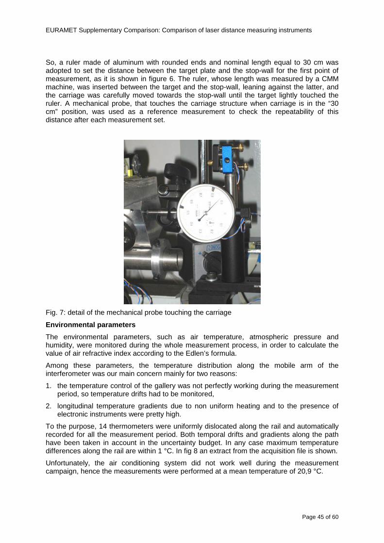
EURAMET Supplementary Comparison Comparison of laser distance measuring instruments
Page 46 of 60
Fig 8 each curve represents the temperature distribution along the rail during the measurements campaign
Carriage waving
Since the rail is not perfectly straight and the measurement laser is not coincident with the measurement beam the Abbegrave error due to waving of the target must be considered A quantitative measurement and a qualitative measurement were carried out With an electronic level placed on the carriage the straightness on the vertical plane has been mapped with a half meter resolution (the data are reported in fig 9) With a laser placed on the carriage the horizontal and vertical waving are qualitatively compared by looking at the movements of the light spot on a target fixed to the rail end As a conclusion the horizontal and vertical waving are comparable in magnitude and the peak to peak error is of the order of 300 arcseconds
Fig 9 vertical waving of the target measured by an electronic level placed on the carriage
EURAMET Supplementary Comparison Comparison of laser distance measuring instruments
Page 47 of 60
Measurement procedure
The measurements were carried out according to the following procedure
The target was set in the starting position with the procedure described above
In sequence the four EDMs are positioned on the base the horizontal and vertical tilt are adjusted and the distance measurement is recorded An additional fifth EDM (Bosh DLE 150 property of INRiM) was included in the measurement sequence Each EDM is placed on the base and gently pushed against the reference wall in such a way that the measurement laser beam starting point is the same for all EDMs Than the horizontal and vertical angles were adjusted in order to hit the central point of the target indicated with two black marks (see pictures 3 and 6) with ldquovisualrdquo alignment The measurement button is then pressed several times (typically 5) and the average reading is recorded Typical dispersion between readings is within few last digit units In case the dispersion between readings is too large the anomaly is recorded
The carriage was then moved in the next position (about 5 m) and the measurement sequence was repeated for the 5 EDMs The operation is repeated up to 25 m The 25 m measurement is than repeated again as well as all the points till the first one so that each point is measured twice each set Since the carriage movement is ldquoopen looprdquo the positioning of the carriage was not exactly in the nominal 5 m intervals For each positioning the incremental displacement is measured by the interferometer in the Doppler mode Finally the measured values were averaged in order to give a single value for each nominal position
At the end of the measurement set when the carriage is at the 30 cm position again the sum of the interferometric measurements should be very close to zero The residual value is compared with the difference between the first and the final measurements of the mechanical probe The difference must be within the uncertainty of the Doppler technique otherwise some error occurred in the measurement set that must be repeated
At the end of the session 10 complete sets of measurements recorded from the 20th to the 30th of January 2012 have been considered for this report
Additional remarks
Effect of laser pointing
During a preliminary set of measurements we noticed a strong and unexpected dependence of the measurement result on the position of the laser spot on the target Indeed since no particular instructions were given about the relative position of the laser spot on target position (except to exclude the central joint between the two halves) we decided to work relatively close to the right side of the target -closer to the interferometer beam- in order to reduce the Abbegrave error We noticed very large errors at large distances in particular of the Leica DISTO D3a (see figure 10)
EURAMET Supplementary Comparison Comparison of laser distance measuring instruments
Page 48 of 60
Fig 10 errors of each EDM In a preliminary set of measurements
We also noticed that this error was strongly dependent on the position of the spot on the target For this reason we carried out a set of measurements at the maximum length in different positions of the target from one edge to the other according to figure 11 The results are reported in table V
EDM A B C D E
Leica D3a -4 +1 0 +24 +43
+2 0 +42 +40
-1 0 +38
Leica D8 0 0 0 2 +7
0 +12 +23
table V deviations (in mm) from the length measured at point C aiming the laser spot at different positions of the target (notations as in figure 11)
We tried to find an explanation to this effect in the shape of the laser spot if the spot was
EURAMET Supplementary Comparison Comparison of laser distance measuring instruments
Page 49 of 60
particularly defocused or had high diffraction some of the energy could fall out of the target and affect the measurement result In fact the images of the spots (shown in fig 12) do not support this hypothesis Finally we decided to use the center of the (half) target for the comparison
Changing the target
In order to investigate the influence of the target on the measurements a cardboard foil (400 x 400) mm was fixed to the target mounting and a complete set of measurements was performed The results reported in figure 13 and 14 do not show any evidence of a possible dependency of the EDM measurement on the target kind
EURAMET Supplementary Comparison Comparison of laser distance measuring instruments
Page 50 of 60
Measurement at 50 m
Although we are not able to perform traceable length measurements beyond 28 m we wanted to get a sense of EDMs behaviour at longer distances So a target (represented by a rack side wall) was placed at approximately 50 m one after the other the EDMrsquos were positioned on the base and pointed towards the target The measurements were repeated then the target was replaced by the target used for the comparison and a third set of measurements were performed To our great surprise all the EDMrsquos were in good agreement (within 2 or 3 mm for each set of measurement) even those which showed errors of the order of five to ten millimeters at 25 m namely BOSCH DLE 50 and LEICA DISTO D3a Therefore each set of measurements was averaged and the deviations from the mean value are reported in figure 15
EURAMET Supplementary Comparison Comparison of laser distance measuring instruments
Page 51 of 60
Fig 15 Deviations from average value of the measurements At 50 m
EURAMET Supplementary Comparison Comparison of laser distance measuring instruments
Page 52 of 60
A19 CEM Spain
Short description of the measurement bench
To make the measurements of EDMs we have used a reference line made of adjustable supports fixed on a wall of the laboratory Each support is nominally separated five metres from the previous one so we can generate reference lengths up to fifty metres with a pitch of five metres The supports are designed to accommodate both targets and handheld EDMs Distances between supports were measured by using a total station traced to national standards The relative angles of the bases have been measured and corrected
Fig 1 - View of three consecutive supports of the 50 m baseline (left) Lab technician situating an EDM on the first support of the baseline (right)
Length measurement instrument
The baseline was calibrated by using a total station Leica TDA5005 with spherical reflector the calibration uncertainty being 02 mm for k = 2
The target is provided by the comparison The quality of the target was judged as not good due to geometrical constructive errors and the lack of rigidity and stability We measured the flatness of the target surface the distance edge-surface and the angle between them by using a 3D coordinate measuring machine The results of flatness and angle were included in the uncertainty budget and the distance EDM-target was corrected for each EDM due to each beam impinged on a different point of the target
We were not able to measure the distance 0 to 03 m because the baseline pitch is 5 meters and although we are able to measure shorter values in a different facility the target was not appropriate for our bench
EURAMET Supplementary Comparison Comparison of laser distance measuring instruments
Page 53 of 60
Fig 2 - View of an EDM on the first support of the baseline (left) A closer look showing the support adjustments and the origin plate (right)
Fig 3 - View of the comparison target on one of the supports of the baseline (left) A closer look showing the target edge against the support rigid reference (right)
Measurement method
The measurements were carried out by comparison against the known values of the calibrated baseline (metallic references on supports)
Environmental conditions were maintained within the following limits
- Temperature 20 ordmC plusmn 05 ordmC
- Humidity 45 plusmn 10
Each laser distance measuring instrument was placed at the first support of the base and aligned so that the laser beam was perpendicular to the target as indicated by the comparison protocol
For each measurement we took the average of thirty measurements It permitted us to evaluate the repeatability of the instrument
EURAMET Supplementary Comparison Comparison of laser distance measuring instruments
Page 54 of 60
A110 BEV Austria
Short description of the measurement bench
Fig 1 Carriage of tape bench View from the laser interferometer side Retroreflector mounted on the vertical plate the EDM target is mounted on the backside
Fig 2 Support for the DUT Adjustable with 2 translational and 2 rotational degrees of freedom respectively
Fig 3 Setting of the 300 mm starting position Note the rough-and-ready mounted target plate
Fig 4 Laser interferometer side of the bench The DUT is 50 m away on the other side
EURAMET Supplementary Comparison Comparison of laser distance measuring instruments
Page 55 of 60
Measurement procedure 1 The EDM is positioned with the help of a 4-axis positioning stage so that its laser beam is
coaxial with the measurement direction of the laser interferometer (in head on configuration)
2 The EDM is removed from its support The bench carriage is positioned so that the distance of the target plate from the EDM back support is 300 mm A length bar with spherical faces is used for this adjustment The laser interferometer is preset to 300 mm and the EDM is put back on its support
3 At each position 10 consecutive measurements are taken (repeatability) and the carriage is moved to the next position The carriage is manually moved under control of the laser interferometer until it is within plusmn30 microm at the correct position (Exception for the DLE 150 the target is not positioned at 10 m but at 10 m ndash 1 mm to make use of the higher resolution) The indicated (not the nominal) distance of the laser interferometer is recorded for the determination of the deviation
4 After reaching the 50 m position all points are measured in reverse order (bidirectional) Immediately after the last measurement the EDM is removed and the indication using the 300 mm length bar is checked (thus noting a possible drift of the setup)
5 Each instrument was measured 4 times according to this procedure on different days (reproducibility of bench and instrument)
Length measurement instrument
Agilent laser interferometer with long range option The bench was completed short time before performing these measurement So the characterisation was not complete and the respective measurement uncertainty of the laser interferometer is estimated rather high But anyway its contribution to the overall uncertainty can nearly be neglected
Additional remarks
The uncertainty originating from the DUT is the dominating uncertainty contribution Specifically the resolution of the two Bosch instruments (1 mm) and the repeatability are the largest contributions For the DLA 50 the pooled standard deviation of a reading at 50 m is larger than 2 mm Moreover the length dependence is not a simple function
All of the instruments show a significant deviation of the laser beam from the normal of the back (reference) face of the instrument The measured angles reach from 04deg (D3a) to 11deg (DLE 50) This leads depending on the outer dimensions of the instruments to a constant uncertainty contribution of 02 mm in our setup It must be noted that the reference faces are not well defined in most of the instruments
The reproducibility is quite different for the four instruments so only part of it originates from the setup For CMC claims we will use the standard uncertainty value of the most reproducible instrument (D3a) which amounts to 013 mm For an ideal instrument with a resolution of 01 mm and perfect repeatability we would thus have a constant expanded uncertainty of 053 mm up to 50 m
EURAMET Supplementary Comparison Comparison of laser distance measuring instruments
Page 56 of 60
A111 JV Norway
Short description of measurement bench
EDM under calibration and the reference system are aligned along a 50 m measurement bench with rails to carry the linear movement of a target plate for the EDM and a corner cube reflector for the reference system The distance between parallel axis of EDM and axis of the reference system is 130 mm Abbe error due to angle errors for the movement is smaller than 01 mm and is corrected for at each measurement point At long lengths an aperture is used approximately midway between the target plate and the EDM to avoid interfering stray light to the EDM
Alignment procedure
1) Alignment of reference system to the movement of the carriage (rails)
2) Alignment of the EDM to the movement of the carriage (rails)
3) Alignment of a plane mirror at the position of the target plate using back-reflection to the EDM output (normal incident of light on the mirror)
4) Take out the EDM and align the zero reference plate at the back of the EDM to the plane mirror
5) The mirror is replaced by the target plate and the target plate is aligned to the zero reference plate
6) Zero setting of the reference measurement system when target plate is at zero distance to the reference plate at the back of the EDM
7) Put the EDM back in position and realign it to the movement of the carriage (rails)
8) Zero setting of the EDM to the reference plate
Image 1) Image 2) Image 3) Image 4)
Image 1) Items 5) ndash 6) in alignment procedure
Fixture for HP linear interferometer is seen bottom right Part of Wyler instrument is seen to the left blue colour
Image 2) Items 7) and 8) in alignment procedure
Micrometer screws for angle alignment in two directions and linear translation for zero setting of the EDM Push button on the EDM is positioned at the tilting point of the angle adjustment table to maximize stability during measurement HP 5519 A laser head is seen to the right
Image 3) Ready to measure at selected distances from zero point the reference plate
Image 4) EDM spot size at 50 m
Length measurement instrument
- Hewlett Packard Dynamic Calibrator 5519 A (max range 80 m)
- Pressure air temperature humidity Vaisala
EURAMET Supplementary Comparison Comparison of laser distance measuring instruments
Page 57 of 60
- Digital high resolution angle measurement Wyler
I used our own target plate which is of the same type as enclosed in the artefact suitcase article number 766560 from Leica but with reduced size width x hight = 90 x 137 mm
The zero reference plate is of similar type and size
Before measurements batteries of EDMs were switched to new batteries Old batteries are switched back after calibration
For L gt 5 m an aperture of similar size as the target plate is used approximately midway between the EDM and the target plate
Additional remarks
Reports on EDM indicated values at each measurement point is the average value of n = 5 repetitions A linear model of the standard deviation for the repeatability of the EDM readings at different lengths is estimated using m = 20 repetitions at least 5 positions along the scale An estimate of the length dependent repeatability is made for each instrument
The expanded uncertainty U(95) is rounded up to the limiting resolution of 1 mm in the interval 10 m to 40 m for Bosch GLM 150
After the calibration we also estimated the angle error of the optical axis of the EDM to its back plane (back reference of EDM) Bosch DLE 50 26 mrad up measured at 50 m Bosch GLM 150 8 mrad to the left measured at 50 m Leica DISTO D3a 37 mrad down measured at 20 m Leica DISTO D8 2 mrad to the left and 4 mrad down (45 mrad total) measured at 20 m
The distance between parallel walls will be measured too large if the back plane is assumed to be normal to the optical axis of the EDM by ∆LL = (1cosα ndash 1) Bosch DLE 50 ∆LL = 340 ppm (∆L = 17 mm at L = 50 m) Bosch GLM 150 ∆LL = 32 ppm (∆L = 16 mm at L = 50 m) Leica DISTO D3a ∆LL = 7 ppm (∆L = 034 mm at L = 50 m) Leica DISTO D8 ∆LL = 10 ppm (∆L = 05 mm at L = 50 m)
EURAMET Supplementary Comparison Comparison of laser distance measuring instruments
Page 58 of 60
A112 METAS Switzerland
Short description of measurement bench (photo recom mended)
50 m bench with laser interferometer (see photo detailed description in Michel Degoumois Un Long laboratoire de mesure OFMETinfo Vol5 No 2 1998)
Length measurement instrument
HP 5529 B laser interferometer range 80 m
EURAMET Supplementary Comparison Comparison of laser distance measuring instruments
Page 59 of 60
A113 GUM Poland
Short description of measurement bench
The 50 m bench is situated in the corridor laboratory located in the basement and has its own air conditioning system with air temperature 20 plusmn 1 degC and humidity 50 plusmn 10 RH The measuring carriage is carried microscope with CCD camera and the optics associated with the interferometer The carriage is driven using belt-transmission and electrical engine with remote ndash controlled variable speed drive
The EDM was placed on the fixed adjustable plate on the other end than laser interferometer The target plate of the EDM was placed on the measuring carriage For each EDM 3 series of measurement were done Before the each measurement EDM was repositioned and aligned again
Length measurement instrument
1 Laser interferometer HP 5529A with long-range option laser head HP 5519A
2 Ambient measurement system number and location of sensors - 20 air temperature sensors type YSI with KEITHLEY multimeter they are placed very
close to axis of the laser beam - air pressure and humidity are measured with Vaisala barometer and
thermohigrometer - CO2 content was measured with analyzer made by Intelli Charge type SPN 4462
EURAMET Supplementary Comparison Comparison of laser distance measuring instruments
Page 60 of 60
Appendix 2 Corrections of reports
131 CEM Spain
CEM reported two errors in their report
1) Bosch GLM 150 EDM error for 35 m should be -08 mm instead of the indicated 08 mm
2) Leica DISTO D8 EDM error for 35 m should be -019 mm instead of the indicated 019 mm
Proposed corrections have been included in Tables 2 and 4 of the Final Report
132 AS Metrosert Estonia
AS Metrosert reported mixed up of all results for Bosch DLE 50 and Bosch GLM 150 The results and uncertainties sent for DLE 50 was results for GLM 150 and vice versa
Proposed corrections have been included in Tables 1 and 2 of the Final Report
133 INRIM Italy
Among the data reported from INRIM some anomalies were found in the measurements of BOSCH DLE 50 and LEICA DISTO D3a at distances of 20 and 25 m
After preliminary discussion on Draft A it was understood that those anomalies could be explained as a sensitivity of said instruments to the laser light that once diffused by the target is reflected by surfaces parallel to the measurement axis and detected together with the wanted signal The superimposition of the two signals can cause a ldquopullingrdquo effect leading to an overestimation of the distance being the reflected path always longer than the direct one Indeed in the INRIMrsquos set-up the target was mounted pretty close to the flat rail used for the carriage movement being likely responsible for unwanted reflections that disturbed the measurements
Since the errors reported in INRIMrsquos measurements can be ascribed to a defect of BOSCH DLE 50 and LEICA DISTO D3a andor to a lack of description of the working conditions of said instruments INRIM asked to eliminate its measurement points at 20 and 25 m of said instruments from the comparison
Proposed corrections have been included in Tables 1 and 3 of the Final Report
134 JV Norway
Justervesenet has changed the procedure and introduced two apertures instead of only one aperture (iris) which was positioned at half distance between EDM and target The reason is that the reference beam also has an aperture and it is positioned right below the beam from the EDM (130 mm distance between axes) Some diffusively reflected stray light from the EDM target might enter the aperture for the reference beam reflect at the measurement table and reach the detector of the EDM In our calibration set-up we have only seen problems at L gt 30 m We will position the first aperture at ca 5 m from the EDM and then the second aperture at ca 25 m This combination of two apertures will effectively eliminate interference of stray light from the measurement table to the EDM detector for all lengths up to 50 m
Justervesenet also increases the uncertainty component regarding repeatability reproducibility so that the expanded uncertainty increases from 14 mm to 15 mm
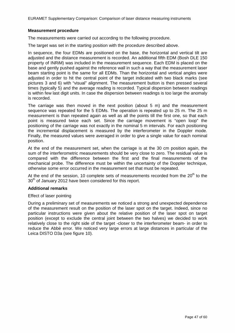
EURAMET Supplementary Comparison Comparison of laser distance measuring instruments
Page 47 of 60
Measurement procedure
The measurements were carried out according to the following procedure
The target was set in the starting position with the procedure described above
In sequence the four EDMs are positioned on the base the horizontal and vertical tilt are adjusted and the distance measurement is recorded An additional fifth EDM (Bosh DLE 150 property of INRiM) was included in the measurement sequence Each EDM is placed on the base and gently pushed against the reference wall in such a way that the measurement laser beam starting point is the same for all EDMs Than the horizontal and vertical angles were adjusted in order to hit the central point of the target indicated with two black marks (see pictures 3 and 6) with ldquovisualrdquo alignment The measurement button is then pressed several times (typically 5) and the average reading is recorded Typical dispersion between readings is within few last digit units In case the dispersion between readings is too large the anomaly is recorded
The carriage was then moved in the next position (about 5 m) and the measurement sequence was repeated for the 5 EDMs The operation is repeated up to 25 m The 25 m measurement is than repeated again as well as all the points till the first one so that each point is measured twice each set Since the carriage movement is ldquoopen looprdquo the positioning of the carriage was not exactly in the nominal 5 m intervals For each positioning the incremental displacement is measured by the interferometer in the Doppler mode Finally the measured values were averaged in order to give a single value for each nominal position
At the end of the measurement set when the carriage is at the 30 cm position again the sum of the interferometric measurements should be very close to zero The residual value is compared with the difference between the first and the final measurements of the mechanical probe The difference must be within the uncertainty of the Doppler technique otherwise some error occurred in the measurement set that must be repeated
At the end of the session 10 complete sets of measurements recorded from the 20th to the 30th of January 2012 have been considered for this report
Additional remarks
Effect of laser pointing
During a preliminary set of measurements we noticed a strong and unexpected dependence of the measurement result on the position of the laser spot on the target Indeed since no particular instructions were given about the relative position of the laser spot on target position (except to exclude the central joint between the two halves) we decided to work relatively close to the right side of the target -closer to the interferometer beam- in order to reduce the Abbegrave error We noticed very large errors at large distances in particular of the Leica DISTO D3a (see figure 10)
EURAMET Supplementary Comparison Comparison of laser distance measuring instruments
Page 48 of 60
Fig 10 errors of each EDM In a preliminary set of measurements
We also noticed that this error was strongly dependent on the position of the spot on the target For this reason we carried out a set of measurements at the maximum length in different positions of the target from one edge to the other according to figure 11 The results are reported in table V
EDM A B C D E
Leica D3a -4 +1 0 +24 +43
+2 0 +42 +40
-1 0 +38
Leica D8 0 0 0 2 +7
0 +12 +23
table V deviations (in mm) from the length measured at point C aiming the laser spot at different positions of the target (notations as in figure 11)
We tried to find an explanation to this effect in the shape of the laser spot if the spot was
EURAMET Supplementary Comparison Comparison of laser distance measuring instruments
Page 49 of 60
particularly defocused or had high diffraction some of the energy could fall out of the target and affect the measurement result In fact the images of the spots (shown in fig 12) do not support this hypothesis Finally we decided to use the center of the (half) target for the comparison
Changing the target
In order to investigate the influence of the target on the measurements a cardboard foil (400 x 400) mm was fixed to the target mounting and a complete set of measurements was performed The results reported in figure 13 and 14 do not show any evidence of a possible dependency of the EDM measurement on the target kind
EURAMET Supplementary Comparison Comparison of laser distance measuring instruments
Page 50 of 60
Measurement at 50 m
Although we are not able to perform traceable length measurements beyond 28 m we wanted to get a sense of EDMs behaviour at longer distances So a target (represented by a rack side wall) was placed at approximately 50 m one after the other the EDMrsquos were positioned on the base and pointed towards the target The measurements were repeated then the target was replaced by the target used for the comparison and a third set of measurements were performed To our great surprise all the EDMrsquos were in good agreement (within 2 or 3 mm for each set of measurement) even those which showed errors of the order of five to ten millimeters at 25 m namely BOSCH DLE 50 and LEICA DISTO D3a Therefore each set of measurements was averaged and the deviations from the mean value are reported in figure 15
EURAMET Supplementary Comparison Comparison of laser distance measuring instruments
Page 51 of 60
Fig 15 Deviations from average value of the measurements At 50 m
EURAMET Supplementary Comparison Comparison of laser distance measuring instruments
Page 52 of 60
A19 CEM Spain
Short description of the measurement bench
To make the measurements of EDMs we have used a reference line made of adjustable supports fixed on a wall of the laboratory Each support is nominally separated five metres from the previous one so we can generate reference lengths up to fifty metres with a pitch of five metres The supports are designed to accommodate both targets and handheld EDMs Distances between supports were measured by using a total station traced to national standards The relative angles of the bases have been measured and corrected
Fig 1 - View of three consecutive supports of the 50 m baseline (left) Lab technician situating an EDM on the first support of the baseline (right)
Length measurement instrument
The baseline was calibrated by using a total station Leica TDA5005 with spherical reflector the calibration uncertainty being 02 mm for k = 2
The target is provided by the comparison The quality of the target was judged as not good due to geometrical constructive errors and the lack of rigidity and stability We measured the flatness of the target surface the distance edge-surface and the angle between them by using a 3D coordinate measuring machine The results of flatness and angle were included in the uncertainty budget and the distance EDM-target was corrected for each EDM due to each beam impinged on a different point of the target
We were not able to measure the distance 0 to 03 m because the baseline pitch is 5 meters and although we are able to measure shorter values in a different facility the target was not appropriate for our bench
EURAMET Supplementary Comparison Comparison of laser distance measuring instruments
Page 53 of 60
Fig 2 - View of an EDM on the first support of the baseline (left) A closer look showing the support adjustments and the origin plate (right)
Fig 3 - View of the comparison target on one of the supports of the baseline (left) A closer look showing the target edge against the support rigid reference (right)
Measurement method
The measurements were carried out by comparison against the known values of the calibrated baseline (metallic references on supports)
Environmental conditions were maintained within the following limits
- Temperature 20 ordmC plusmn 05 ordmC
- Humidity 45 plusmn 10
Each laser distance measuring instrument was placed at the first support of the base and aligned so that the laser beam was perpendicular to the target as indicated by the comparison protocol
For each measurement we took the average of thirty measurements It permitted us to evaluate the repeatability of the instrument
EURAMET Supplementary Comparison Comparison of laser distance measuring instruments
Page 54 of 60
A110 BEV Austria
Short description of the measurement bench
Fig 1 Carriage of tape bench View from the laser interferometer side Retroreflector mounted on the vertical plate the EDM target is mounted on the backside
Fig 2 Support for the DUT Adjustable with 2 translational and 2 rotational degrees of freedom respectively
Fig 3 Setting of the 300 mm starting position Note the rough-and-ready mounted target plate
Fig 4 Laser interferometer side of the bench The DUT is 50 m away on the other side
EURAMET Supplementary Comparison Comparison of laser distance measuring instruments
Page 55 of 60
Measurement procedure 1 The EDM is positioned with the help of a 4-axis positioning stage so that its laser beam is
coaxial with the measurement direction of the laser interferometer (in head on configuration)
2 The EDM is removed from its support The bench carriage is positioned so that the distance of the target plate from the EDM back support is 300 mm A length bar with spherical faces is used for this adjustment The laser interferometer is preset to 300 mm and the EDM is put back on its support
3 At each position 10 consecutive measurements are taken (repeatability) and the carriage is moved to the next position The carriage is manually moved under control of the laser interferometer until it is within plusmn30 microm at the correct position (Exception for the DLE 150 the target is not positioned at 10 m but at 10 m ndash 1 mm to make use of the higher resolution) The indicated (not the nominal) distance of the laser interferometer is recorded for the determination of the deviation
4 After reaching the 50 m position all points are measured in reverse order (bidirectional) Immediately after the last measurement the EDM is removed and the indication using the 300 mm length bar is checked (thus noting a possible drift of the setup)
5 Each instrument was measured 4 times according to this procedure on different days (reproducibility of bench and instrument)
Length measurement instrument
Agilent laser interferometer with long range option The bench was completed short time before performing these measurement So the characterisation was not complete and the respective measurement uncertainty of the laser interferometer is estimated rather high But anyway its contribution to the overall uncertainty can nearly be neglected
Additional remarks
The uncertainty originating from the DUT is the dominating uncertainty contribution Specifically the resolution of the two Bosch instruments (1 mm) and the repeatability are the largest contributions For the DLA 50 the pooled standard deviation of a reading at 50 m is larger than 2 mm Moreover the length dependence is not a simple function
All of the instruments show a significant deviation of the laser beam from the normal of the back (reference) face of the instrument The measured angles reach from 04deg (D3a) to 11deg (DLE 50) This leads depending on the outer dimensions of the instruments to a constant uncertainty contribution of 02 mm in our setup It must be noted that the reference faces are not well defined in most of the instruments
The reproducibility is quite different for the four instruments so only part of it originates from the setup For CMC claims we will use the standard uncertainty value of the most reproducible instrument (D3a) which amounts to 013 mm For an ideal instrument with a resolution of 01 mm and perfect repeatability we would thus have a constant expanded uncertainty of 053 mm up to 50 m
EURAMET Supplementary Comparison Comparison of laser distance measuring instruments
Page 56 of 60
A111 JV Norway
Short description of measurement bench
EDM under calibration and the reference system are aligned along a 50 m measurement bench with rails to carry the linear movement of a target plate for the EDM and a corner cube reflector for the reference system The distance between parallel axis of EDM and axis of the reference system is 130 mm Abbe error due to angle errors for the movement is smaller than 01 mm and is corrected for at each measurement point At long lengths an aperture is used approximately midway between the target plate and the EDM to avoid interfering stray light to the EDM
Alignment procedure
1) Alignment of reference system to the movement of the carriage (rails)
2) Alignment of the EDM to the movement of the carriage (rails)
3) Alignment of a plane mirror at the position of the target plate using back-reflection to the EDM output (normal incident of light on the mirror)
4) Take out the EDM and align the zero reference plate at the back of the EDM to the plane mirror
5) The mirror is replaced by the target plate and the target plate is aligned to the zero reference plate
6) Zero setting of the reference measurement system when target plate is at zero distance to the reference plate at the back of the EDM
7) Put the EDM back in position and realign it to the movement of the carriage (rails)
8) Zero setting of the EDM to the reference plate
Image 1) Image 2) Image 3) Image 4)
Image 1) Items 5) ndash 6) in alignment procedure
Fixture for HP linear interferometer is seen bottom right Part of Wyler instrument is seen to the left blue colour
Image 2) Items 7) and 8) in alignment procedure
Micrometer screws for angle alignment in two directions and linear translation for zero setting of the EDM Push button on the EDM is positioned at the tilting point of the angle adjustment table to maximize stability during measurement HP 5519 A laser head is seen to the right
Image 3) Ready to measure at selected distances from zero point the reference plate
Image 4) EDM spot size at 50 m
Length measurement instrument
- Hewlett Packard Dynamic Calibrator 5519 A (max range 80 m)
- Pressure air temperature humidity Vaisala
EURAMET Supplementary Comparison Comparison of laser distance measuring instruments
Page 57 of 60
- Digital high resolution angle measurement Wyler
I used our own target plate which is of the same type as enclosed in the artefact suitcase article number 766560 from Leica but with reduced size width x hight = 90 x 137 mm
The zero reference plate is of similar type and size
Before measurements batteries of EDMs were switched to new batteries Old batteries are switched back after calibration
For L gt 5 m an aperture of similar size as the target plate is used approximately midway between the EDM and the target plate
Additional remarks
Reports on EDM indicated values at each measurement point is the average value of n = 5 repetitions A linear model of the standard deviation for the repeatability of the EDM readings at different lengths is estimated using m = 20 repetitions at least 5 positions along the scale An estimate of the length dependent repeatability is made for each instrument
The expanded uncertainty U(95) is rounded up to the limiting resolution of 1 mm in the interval 10 m to 40 m for Bosch GLM 150
After the calibration we also estimated the angle error of the optical axis of the EDM to its back plane (back reference of EDM) Bosch DLE 50 26 mrad up measured at 50 m Bosch GLM 150 8 mrad to the left measured at 50 m Leica DISTO D3a 37 mrad down measured at 20 m Leica DISTO D8 2 mrad to the left and 4 mrad down (45 mrad total) measured at 20 m
The distance between parallel walls will be measured too large if the back plane is assumed to be normal to the optical axis of the EDM by ∆LL = (1cosα ndash 1) Bosch DLE 50 ∆LL = 340 ppm (∆L = 17 mm at L = 50 m) Bosch GLM 150 ∆LL = 32 ppm (∆L = 16 mm at L = 50 m) Leica DISTO D3a ∆LL = 7 ppm (∆L = 034 mm at L = 50 m) Leica DISTO D8 ∆LL = 10 ppm (∆L = 05 mm at L = 50 m)
EURAMET Supplementary Comparison Comparison of laser distance measuring instruments
Page 58 of 60
A112 METAS Switzerland
Short description of measurement bench (photo recom mended)
50 m bench with laser interferometer (see photo detailed description in Michel Degoumois Un Long laboratoire de mesure OFMETinfo Vol5 No 2 1998)
Length measurement instrument
HP 5529 B laser interferometer range 80 m
EURAMET Supplementary Comparison Comparison of laser distance measuring instruments
Page 59 of 60
A113 GUM Poland
Short description of measurement bench
The 50 m bench is situated in the corridor laboratory located in the basement and has its own air conditioning system with air temperature 20 plusmn 1 degC and humidity 50 plusmn 10 RH The measuring carriage is carried microscope with CCD camera and the optics associated with the interferometer The carriage is driven using belt-transmission and electrical engine with remote ndash controlled variable speed drive
The EDM was placed on the fixed adjustable plate on the other end than laser interferometer The target plate of the EDM was placed on the measuring carriage For each EDM 3 series of measurement were done Before the each measurement EDM was repositioned and aligned again
Length measurement instrument
1 Laser interferometer HP 5529A with long-range option laser head HP 5519A
2 Ambient measurement system number and location of sensors - 20 air temperature sensors type YSI with KEITHLEY multimeter they are placed very
close to axis of the laser beam - air pressure and humidity are measured with Vaisala barometer and
thermohigrometer - CO2 content was measured with analyzer made by Intelli Charge type SPN 4462
EURAMET Supplementary Comparison Comparison of laser distance measuring instruments
Page 60 of 60
Appendix 2 Corrections of reports
131 CEM Spain
CEM reported two errors in their report
1) Bosch GLM 150 EDM error for 35 m should be -08 mm instead of the indicated 08 mm
2) Leica DISTO D8 EDM error for 35 m should be -019 mm instead of the indicated 019 mm
Proposed corrections have been included in Tables 2 and 4 of the Final Report
132 AS Metrosert Estonia
AS Metrosert reported mixed up of all results for Bosch DLE 50 and Bosch GLM 150 The results and uncertainties sent for DLE 50 was results for GLM 150 and vice versa
Proposed corrections have been included in Tables 1 and 2 of the Final Report
133 INRIM Italy
Among the data reported from INRIM some anomalies were found in the measurements of BOSCH DLE 50 and LEICA DISTO D3a at distances of 20 and 25 m
After preliminary discussion on Draft A it was understood that those anomalies could be explained as a sensitivity of said instruments to the laser light that once diffused by the target is reflected by surfaces parallel to the measurement axis and detected together with the wanted signal The superimposition of the two signals can cause a ldquopullingrdquo effect leading to an overestimation of the distance being the reflected path always longer than the direct one Indeed in the INRIMrsquos set-up the target was mounted pretty close to the flat rail used for the carriage movement being likely responsible for unwanted reflections that disturbed the measurements
Since the errors reported in INRIMrsquos measurements can be ascribed to a defect of BOSCH DLE 50 and LEICA DISTO D3a andor to a lack of description of the working conditions of said instruments INRIM asked to eliminate its measurement points at 20 and 25 m of said instruments from the comparison
Proposed corrections have been included in Tables 1 and 3 of the Final Report
134 JV Norway
Justervesenet has changed the procedure and introduced two apertures instead of only one aperture (iris) which was positioned at half distance between EDM and target The reason is that the reference beam also has an aperture and it is positioned right below the beam from the EDM (130 mm distance between axes) Some diffusively reflected stray light from the EDM target might enter the aperture for the reference beam reflect at the measurement table and reach the detector of the EDM In our calibration set-up we have only seen problems at L gt 30 m We will position the first aperture at ca 5 m from the EDM and then the second aperture at ca 25 m This combination of two apertures will effectively eliminate interference of stray light from the measurement table to the EDM detector for all lengths up to 50 m
Justervesenet also increases the uncertainty component regarding repeatability reproducibility so that the expanded uncertainty increases from 14 mm to 15 mm
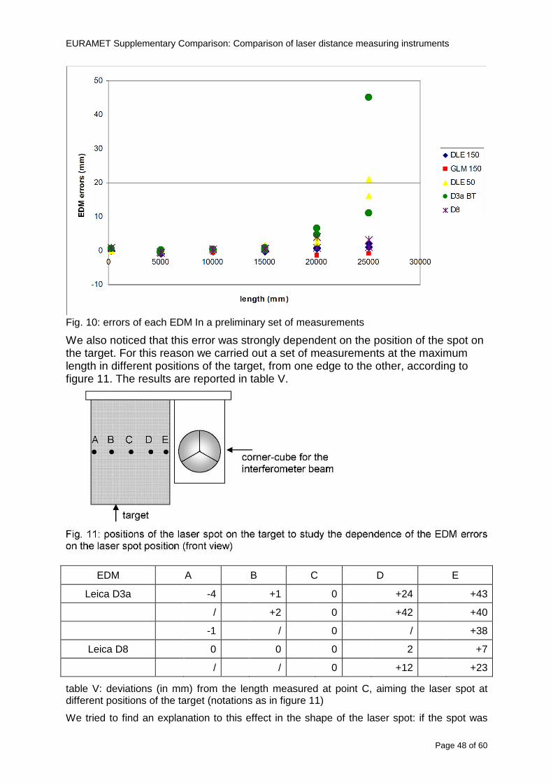
EURAMET Supplementary Comparison Comparison of laser distance measuring instruments
Page 48 of 60
Fig 10 errors of each EDM In a preliminary set of measurements
We also noticed that this error was strongly dependent on the position of the spot on the target For this reason we carried out a set of measurements at the maximum length in different positions of the target from one edge to the other according to figure 11 The results are reported in table V
EDM A B C D E
Leica D3a -4 +1 0 +24 +43
+2 0 +42 +40
-1 0 +38
Leica D8 0 0 0 2 +7
0 +12 +23
table V deviations (in mm) from the length measured at point C aiming the laser spot at different positions of the target (notations as in figure 11)
We tried to find an explanation to this effect in the shape of the laser spot if the spot was
EURAMET Supplementary Comparison Comparison of laser distance measuring instruments
Page 49 of 60
particularly defocused or had high diffraction some of the energy could fall out of the target and affect the measurement result In fact the images of the spots (shown in fig 12) do not support this hypothesis Finally we decided to use the center of the (half) target for the comparison
Changing the target
In order to investigate the influence of the target on the measurements a cardboard foil (400 x 400) mm was fixed to the target mounting and a complete set of measurements was performed The results reported in figure 13 and 14 do not show any evidence of a possible dependency of the EDM measurement on the target kind
EURAMET Supplementary Comparison Comparison of laser distance measuring instruments
Page 50 of 60
Measurement at 50 m
Although we are not able to perform traceable length measurements beyond 28 m we wanted to get a sense of EDMs behaviour at longer distances So a target (represented by a rack side wall) was placed at approximately 50 m one after the other the EDMrsquos were positioned on the base and pointed towards the target The measurements were repeated then the target was replaced by the target used for the comparison and a third set of measurements were performed To our great surprise all the EDMrsquos were in good agreement (within 2 or 3 mm for each set of measurement) even those which showed errors of the order of five to ten millimeters at 25 m namely BOSCH DLE 50 and LEICA DISTO D3a Therefore each set of measurements was averaged and the deviations from the mean value are reported in figure 15
EURAMET Supplementary Comparison Comparison of laser distance measuring instruments
Page 51 of 60
Fig 15 Deviations from average value of the measurements At 50 m
EURAMET Supplementary Comparison Comparison of laser distance measuring instruments
Page 52 of 60
A19 CEM Spain
Short description of the measurement bench
To make the measurements of EDMs we have used a reference line made of adjustable supports fixed on a wall of the laboratory Each support is nominally separated five metres from the previous one so we can generate reference lengths up to fifty metres with a pitch of five metres The supports are designed to accommodate both targets and handheld EDMs Distances between supports were measured by using a total station traced to national standards The relative angles of the bases have been measured and corrected
Fig 1 - View of three consecutive supports of the 50 m baseline (left) Lab technician situating an EDM on the first support of the baseline (right)
Length measurement instrument
The baseline was calibrated by using a total station Leica TDA5005 with spherical reflector the calibration uncertainty being 02 mm for k = 2
The target is provided by the comparison The quality of the target was judged as not good due to geometrical constructive errors and the lack of rigidity and stability We measured the flatness of the target surface the distance edge-surface and the angle between them by using a 3D coordinate measuring machine The results of flatness and angle were included in the uncertainty budget and the distance EDM-target was corrected for each EDM due to each beam impinged on a different point of the target
We were not able to measure the distance 0 to 03 m because the baseline pitch is 5 meters and although we are able to measure shorter values in a different facility the target was not appropriate for our bench
EURAMET Supplementary Comparison Comparison of laser distance measuring instruments
Page 53 of 60
Fig 2 - View of an EDM on the first support of the baseline (left) A closer look showing the support adjustments and the origin plate (right)
Fig 3 - View of the comparison target on one of the supports of the baseline (left) A closer look showing the target edge against the support rigid reference (right)
Measurement method
The measurements were carried out by comparison against the known values of the calibrated baseline (metallic references on supports)
Environmental conditions were maintained within the following limits
- Temperature 20 ordmC plusmn 05 ordmC
- Humidity 45 plusmn 10
Each laser distance measuring instrument was placed at the first support of the base and aligned so that the laser beam was perpendicular to the target as indicated by the comparison protocol
For each measurement we took the average of thirty measurements It permitted us to evaluate the repeatability of the instrument
EURAMET Supplementary Comparison Comparison of laser distance measuring instruments
Page 54 of 60
A110 BEV Austria
Short description of the measurement bench
Fig 1 Carriage of tape bench View from the laser interferometer side Retroreflector mounted on the vertical plate the EDM target is mounted on the backside
Fig 2 Support for the DUT Adjustable with 2 translational and 2 rotational degrees of freedom respectively
Fig 3 Setting of the 300 mm starting position Note the rough-and-ready mounted target plate
Fig 4 Laser interferometer side of the bench The DUT is 50 m away on the other side
EURAMET Supplementary Comparison Comparison of laser distance measuring instruments
Page 55 of 60
Measurement procedure 1 The EDM is positioned with the help of a 4-axis positioning stage so that its laser beam is
coaxial with the measurement direction of the laser interferometer (in head on configuration)
2 The EDM is removed from its support The bench carriage is positioned so that the distance of the target plate from the EDM back support is 300 mm A length bar with spherical faces is used for this adjustment The laser interferometer is preset to 300 mm and the EDM is put back on its support
3 At each position 10 consecutive measurements are taken (repeatability) and the carriage is moved to the next position The carriage is manually moved under control of the laser interferometer until it is within plusmn30 microm at the correct position (Exception for the DLE 150 the target is not positioned at 10 m but at 10 m ndash 1 mm to make use of the higher resolution) The indicated (not the nominal) distance of the laser interferometer is recorded for the determination of the deviation
4 After reaching the 50 m position all points are measured in reverse order (bidirectional) Immediately after the last measurement the EDM is removed and the indication using the 300 mm length bar is checked (thus noting a possible drift of the setup)
5 Each instrument was measured 4 times according to this procedure on different days (reproducibility of bench and instrument)
Length measurement instrument
Agilent laser interferometer with long range option The bench was completed short time before performing these measurement So the characterisation was not complete and the respective measurement uncertainty of the laser interferometer is estimated rather high But anyway its contribution to the overall uncertainty can nearly be neglected
Additional remarks
The uncertainty originating from the DUT is the dominating uncertainty contribution Specifically the resolution of the two Bosch instruments (1 mm) and the repeatability are the largest contributions For the DLA 50 the pooled standard deviation of a reading at 50 m is larger than 2 mm Moreover the length dependence is not a simple function
All of the instruments show a significant deviation of the laser beam from the normal of the back (reference) face of the instrument The measured angles reach from 04deg (D3a) to 11deg (DLE 50) This leads depending on the outer dimensions of the instruments to a constant uncertainty contribution of 02 mm in our setup It must be noted that the reference faces are not well defined in most of the instruments
The reproducibility is quite different for the four instruments so only part of it originates from the setup For CMC claims we will use the standard uncertainty value of the most reproducible instrument (D3a) which amounts to 013 mm For an ideal instrument with a resolution of 01 mm and perfect repeatability we would thus have a constant expanded uncertainty of 053 mm up to 50 m
EURAMET Supplementary Comparison Comparison of laser distance measuring instruments
Page 56 of 60
A111 JV Norway
Short description of measurement bench
EDM under calibration and the reference system are aligned along a 50 m measurement bench with rails to carry the linear movement of a target plate for the EDM and a corner cube reflector for the reference system The distance between parallel axis of EDM and axis of the reference system is 130 mm Abbe error due to angle errors for the movement is smaller than 01 mm and is corrected for at each measurement point At long lengths an aperture is used approximately midway between the target plate and the EDM to avoid interfering stray light to the EDM
Alignment procedure
1) Alignment of reference system to the movement of the carriage (rails)
2) Alignment of the EDM to the movement of the carriage (rails)
3) Alignment of a plane mirror at the position of the target plate using back-reflection to the EDM output (normal incident of light on the mirror)
4) Take out the EDM and align the zero reference plate at the back of the EDM to the plane mirror
5) The mirror is replaced by the target plate and the target plate is aligned to the zero reference plate
6) Zero setting of the reference measurement system when target plate is at zero distance to the reference plate at the back of the EDM
7) Put the EDM back in position and realign it to the movement of the carriage (rails)
8) Zero setting of the EDM to the reference plate
Image 1) Image 2) Image 3) Image 4)
Image 1) Items 5) ndash 6) in alignment procedure
Fixture for HP linear interferometer is seen bottom right Part of Wyler instrument is seen to the left blue colour
Image 2) Items 7) and 8) in alignment procedure
Micrometer screws for angle alignment in two directions and linear translation for zero setting of the EDM Push button on the EDM is positioned at the tilting point of the angle adjustment table to maximize stability during measurement HP 5519 A laser head is seen to the right
Image 3) Ready to measure at selected distances from zero point the reference plate
Image 4) EDM spot size at 50 m
Length measurement instrument
- Hewlett Packard Dynamic Calibrator 5519 A (max range 80 m)
- Pressure air temperature humidity Vaisala
EURAMET Supplementary Comparison Comparison of laser distance measuring instruments
Page 57 of 60
- Digital high resolution angle measurement Wyler
I used our own target plate which is of the same type as enclosed in the artefact suitcase article number 766560 from Leica but with reduced size width x hight = 90 x 137 mm
The zero reference plate is of similar type and size
Before measurements batteries of EDMs were switched to new batteries Old batteries are switched back after calibration
For L gt 5 m an aperture of similar size as the target plate is used approximately midway between the EDM and the target plate
Additional remarks
Reports on EDM indicated values at each measurement point is the average value of n = 5 repetitions A linear model of the standard deviation for the repeatability of the EDM readings at different lengths is estimated using m = 20 repetitions at least 5 positions along the scale An estimate of the length dependent repeatability is made for each instrument
The expanded uncertainty U(95) is rounded up to the limiting resolution of 1 mm in the interval 10 m to 40 m for Bosch GLM 150
After the calibration we also estimated the angle error of the optical axis of the EDM to its back plane (back reference of EDM) Bosch DLE 50 26 mrad up measured at 50 m Bosch GLM 150 8 mrad to the left measured at 50 m Leica DISTO D3a 37 mrad down measured at 20 m Leica DISTO D8 2 mrad to the left and 4 mrad down (45 mrad total) measured at 20 m
The distance between parallel walls will be measured too large if the back plane is assumed to be normal to the optical axis of the EDM by ∆LL = (1cosα ndash 1) Bosch DLE 50 ∆LL = 340 ppm (∆L = 17 mm at L = 50 m) Bosch GLM 150 ∆LL = 32 ppm (∆L = 16 mm at L = 50 m) Leica DISTO D3a ∆LL = 7 ppm (∆L = 034 mm at L = 50 m) Leica DISTO D8 ∆LL = 10 ppm (∆L = 05 mm at L = 50 m)
EURAMET Supplementary Comparison Comparison of laser distance measuring instruments
Page 58 of 60
A112 METAS Switzerland
Short description of measurement bench (photo recom mended)
50 m bench with laser interferometer (see photo detailed description in Michel Degoumois Un Long laboratoire de mesure OFMETinfo Vol5 No 2 1998)
Length measurement instrument
HP 5529 B laser interferometer range 80 m
EURAMET Supplementary Comparison Comparison of laser distance measuring instruments
Page 59 of 60
A113 GUM Poland
Short description of measurement bench
The 50 m bench is situated in the corridor laboratory located in the basement and has its own air conditioning system with air temperature 20 plusmn 1 degC and humidity 50 plusmn 10 RH The measuring carriage is carried microscope with CCD camera and the optics associated with the interferometer The carriage is driven using belt-transmission and electrical engine with remote ndash controlled variable speed drive
The EDM was placed on the fixed adjustable plate on the other end than laser interferometer The target plate of the EDM was placed on the measuring carriage For each EDM 3 series of measurement were done Before the each measurement EDM was repositioned and aligned again
Length measurement instrument
1 Laser interferometer HP 5529A with long-range option laser head HP 5519A
2 Ambient measurement system number and location of sensors - 20 air temperature sensors type YSI with KEITHLEY multimeter they are placed very
close to axis of the laser beam - air pressure and humidity are measured with Vaisala barometer and
thermohigrometer - CO2 content was measured with analyzer made by Intelli Charge type SPN 4462
EURAMET Supplementary Comparison Comparison of laser distance measuring instruments
Page 60 of 60
Appendix 2 Corrections of reports
131 CEM Spain
CEM reported two errors in their report
1) Bosch GLM 150 EDM error for 35 m should be -08 mm instead of the indicated 08 mm
2) Leica DISTO D8 EDM error for 35 m should be -019 mm instead of the indicated 019 mm
Proposed corrections have been included in Tables 2 and 4 of the Final Report
132 AS Metrosert Estonia
AS Metrosert reported mixed up of all results for Bosch DLE 50 and Bosch GLM 150 The results and uncertainties sent for DLE 50 was results for GLM 150 and vice versa
Proposed corrections have been included in Tables 1 and 2 of the Final Report
133 INRIM Italy
Among the data reported from INRIM some anomalies were found in the measurements of BOSCH DLE 50 and LEICA DISTO D3a at distances of 20 and 25 m
After preliminary discussion on Draft A it was understood that those anomalies could be explained as a sensitivity of said instruments to the laser light that once diffused by the target is reflected by surfaces parallel to the measurement axis and detected together with the wanted signal The superimposition of the two signals can cause a ldquopullingrdquo effect leading to an overestimation of the distance being the reflected path always longer than the direct one Indeed in the INRIMrsquos set-up the target was mounted pretty close to the flat rail used for the carriage movement being likely responsible for unwanted reflections that disturbed the measurements
Since the errors reported in INRIMrsquos measurements can be ascribed to a defect of BOSCH DLE 50 and LEICA DISTO D3a andor to a lack of description of the working conditions of said instruments INRIM asked to eliminate its measurement points at 20 and 25 m of said instruments from the comparison
Proposed corrections have been included in Tables 1 and 3 of the Final Report
134 JV Norway
Justervesenet has changed the procedure and introduced two apertures instead of only one aperture (iris) which was positioned at half distance between EDM and target The reason is that the reference beam also has an aperture and it is positioned right below the beam from the EDM (130 mm distance between axes) Some diffusively reflected stray light from the EDM target might enter the aperture for the reference beam reflect at the measurement table and reach the detector of the EDM In our calibration set-up we have only seen problems at L gt 30 m We will position the first aperture at ca 5 m from the EDM and then the second aperture at ca 25 m This combination of two apertures will effectively eliminate interference of stray light from the measurement table to the EDM detector for all lengths up to 50 m
Justervesenet also increases the uncertainty component regarding repeatability reproducibility so that the expanded uncertainty increases from 14 mm to 15 mm
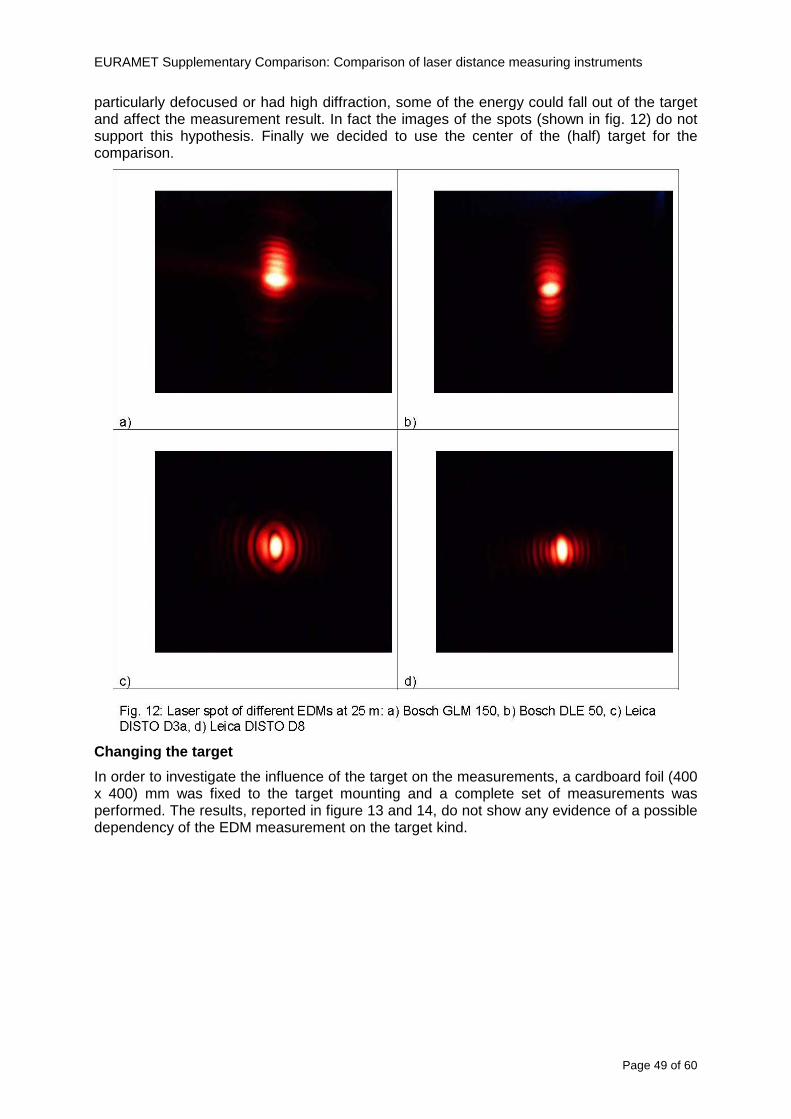
EURAMET Supplementary Comparison Comparison of laser distance measuring instruments
Page 50 of 60
Measurement at 50 m
Although we are not able to perform traceable length measurements beyond 28 m we wanted to get a sense of EDMs behaviour at longer distances So a target (represented by a rack side wall) was placed at approximately 50 m one after the other the EDMrsquos were positioned on the base and pointed towards the target The measurements were repeated then the target was replaced by the target used for the comparison and a third set of measurements were performed To our great surprise all the EDMrsquos were in good agreement (within 2 or 3 mm for each set of measurement) even those which showed errors of the order of five to ten millimeters at 25 m namely BOSCH DLE 50 and LEICA DISTO D3a Therefore each set of measurements was averaged and the deviations from the mean value are reported in figure 15
EURAMET Supplementary Comparison Comparison of laser distance measuring instruments
Page 51 of 60
Fig 15 Deviations from average value of the measurements At 50 m
EURAMET Supplementary Comparison Comparison of laser distance measuring instruments
Page 52 of 60
A19 CEM Spain
Short description of the measurement bench
To make the measurements of EDMs we have used a reference line made of adjustable supports fixed on a wall of the laboratory Each support is nominally separated five metres from the previous one so we can generate reference lengths up to fifty metres with a pitch of five metres The supports are designed to accommodate both targets and handheld EDMs Distances between supports were measured by using a total station traced to national standards The relative angles of the bases have been measured and corrected
Fig 1 - View of three consecutive supports of the 50 m baseline (left) Lab technician situating an EDM on the first support of the baseline (right)
Length measurement instrument
The baseline was calibrated by using a total station Leica TDA5005 with spherical reflector the calibration uncertainty being 02 mm for k = 2
The target is provided by the comparison The quality of the target was judged as not good due to geometrical constructive errors and the lack of rigidity and stability We measured the flatness of the target surface the distance edge-surface and the angle between them by using a 3D coordinate measuring machine The results of flatness and angle were included in the uncertainty budget and the distance EDM-target was corrected for each EDM due to each beam impinged on a different point of the target
We were not able to measure the distance 0 to 03 m because the baseline pitch is 5 meters and although we are able to measure shorter values in a different facility the target was not appropriate for our bench
EURAMET Supplementary Comparison Comparison of laser distance measuring instruments
Page 53 of 60
Fig 2 - View of an EDM on the first support of the baseline (left) A closer look showing the support adjustments and the origin plate (right)
Fig 3 - View of the comparison target on one of the supports of the baseline (left) A closer look showing the target edge against the support rigid reference (right)
Measurement method
The measurements were carried out by comparison against the known values of the calibrated baseline (metallic references on supports)
Environmental conditions were maintained within the following limits
- Temperature 20 ordmC plusmn 05 ordmC
- Humidity 45 plusmn 10
Each laser distance measuring instrument was placed at the first support of the base and aligned so that the laser beam was perpendicular to the target as indicated by the comparison protocol
For each measurement we took the average of thirty measurements It permitted us to evaluate the repeatability of the instrument
EURAMET Supplementary Comparison Comparison of laser distance measuring instruments
Page 54 of 60
A110 BEV Austria
Short description of the measurement bench
Fig 1 Carriage of tape bench View from the laser interferometer side Retroreflector mounted on the vertical plate the EDM target is mounted on the backside
Fig 2 Support for the DUT Adjustable with 2 translational and 2 rotational degrees of freedom respectively
Fig 3 Setting of the 300 mm starting position Note the rough-and-ready mounted target plate
Fig 4 Laser interferometer side of the bench The DUT is 50 m away on the other side
EURAMET Supplementary Comparison Comparison of laser distance measuring instruments
Page 55 of 60
Measurement procedure 1 The EDM is positioned with the help of a 4-axis positioning stage so that its laser beam is
coaxial with the measurement direction of the laser interferometer (in head on configuration)
2 The EDM is removed from its support The bench carriage is positioned so that the distance of the target plate from the EDM back support is 300 mm A length bar with spherical faces is used for this adjustment The laser interferometer is preset to 300 mm and the EDM is put back on its support
3 At each position 10 consecutive measurements are taken (repeatability) and the carriage is moved to the next position The carriage is manually moved under control of the laser interferometer until it is within plusmn30 microm at the correct position (Exception for the DLE 150 the target is not positioned at 10 m but at 10 m ndash 1 mm to make use of the higher resolution) The indicated (not the nominal) distance of the laser interferometer is recorded for the determination of the deviation
4 After reaching the 50 m position all points are measured in reverse order (bidirectional) Immediately after the last measurement the EDM is removed and the indication using the 300 mm length bar is checked (thus noting a possible drift of the setup)
5 Each instrument was measured 4 times according to this procedure on different days (reproducibility of bench and instrument)
Length measurement instrument
Agilent laser interferometer with long range option The bench was completed short time before performing these measurement So the characterisation was not complete and the respective measurement uncertainty of the laser interferometer is estimated rather high But anyway its contribution to the overall uncertainty can nearly be neglected
Additional remarks
The uncertainty originating from the DUT is the dominating uncertainty contribution Specifically the resolution of the two Bosch instruments (1 mm) and the repeatability are the largest contributions For the DLA 50 the pooled standard deviation of a reading at 50 m is larger than 2 mm Moreover the length dependence is not a simple function
All of the instruments show a significant deviation of the laser beam from the normal of the back (reference) face of the instrument The measured angles reach from 04deg (D3a) to 11deg (DLE 50) This leads depending on the outer dimensions of the instruments to a constant uncertainty contribution of 02 mm in our setup It must be noted that the reference faces are not well defined in most of the instruments
The reproducibility is quite different for the four instruments so only part of it originates from the setup For CMC claims we will use the standard uncertainty value of the most reproducible instrument (D3a) which amounts to 013 mm For an ideal instrument with a resolution of 01 mm and perfect repeatability we would thus have a constant expanded uncertainty of 053 mm up to 50 m
EURAMET Supplementary Comparison Comparison of laser distance measuring instruments
Page 56 of 60
A111 JV Norway
Short description of measurement bench
EDM under calibration and the reference system are aligned along a 50 m measurement bench with rails to carry the linear movement of a target plate for the EDM and a corner cube reflector for the reference system The distance between parallel axis of EDM and axis of the reference system is 130 mm Abbe error due to angle errors for the movement is smaller than 01 mm and is corrected for at each measurement point At long lengths an aperture is used approximately midway between the target plate and the EDM to avoid interfering stray light to the EDM
Alignment procedure
1) Alignment of reference system to the movement of the carriage (rails)
2) Alignment of the EDM to the movement of the carriage (rails)
3) Alignment of a plane mirror at the position of the target plate using back-reflection to the EDM output (normal incident of light on the mirror)
4) Take out the EDM and align the zero reference plate at the back of the EDM to the plane mirror
5) The mirror is replaced by the target plate and the target plate is aligned to the zero reference plate
6) Zero setting of the reference measurement system when target plate is at zero distance to the reference plate at the back of the EDM
7) Put the EDM back in position and realign it to the movement of the carriage (rails)
8) Zero setting of the EDM to the reference plate
Image 1) Image 2) Image 3) Image 4)
Image 1) Items 5) ndash 6) in alignment procedure
Fixture for HP linear interferometer is seen bottom right Part of Wyler instrument is seen to the left blue colour
Image 2) Items 7) and 8) in alignment procedure
Micrometer screws for angle alignment in two directions and linear translation for zero setting of the EDM Push button on the EDM is positioned at the tilting point of the angle adjustment table to maximize stability during measurement HP 5519 A laser head is seen to the right
Image 3) Ready to measure at selected distances from zero point the reference plate
Image 4) EDM spot size at 50 m
Length measurement instrument
- Hewlett Packard Dynamic Calibrator 5519 A (max range 80 m)
- Pressure air temperature humidity Vaisala
EURAMET Supplementary Comparison Comparison of laser distance measuring instruments
Page 57 of 60
- Digital high resolution angle measurement Wyler
I used our own target plate which is of the same type as enclosed in the artefact suitcase article number 766560 from Leica but with reduced size width x hight = 90 x 137 mm
The zero reference plate is of similar type and size
Before measurements batteries of EDMs were switched to new batteries Old batteries are switched back after calibration
For L gt 5 m an aperture of similar size as the target plate is used approximately midway between the EDM and the target plate
Additional remarks
Reports on EDM indicated values at each measurement point is the average value of n = 5 repetitions A linear model of the standard deviation for the repeatability of the EDM readings at different lengths is estimated using m = 20 repetitions at least 5 positions along the scale An estimate of the length dependent repeatability is made for each instrument
The expanded uncertainty U(95) is rounded up to the limiting resolution of 1 mm in the interval 10 m to 40 m for Bosch GLM 150
After the calibration we also estimated the angle error of the optical axis of the EDM to its back plane (back reference of EDM) Bosch DLE 50 26 mrad up measured at 50 m Bosch GLM 150 8 mrad to the left measured at 50 m Leica DISTO D3a 37 mrad down measured at 20 m Leica DISTO D8 2 mrad to the left and 4 mrad down (45 mrad total) measured at 20 m
The distance between parallel walls will be measured too large if the back plane is assumed to be normal to the optical axis of the EDM by ∆LL = (1cosα ndash 1) Bosch DLE 50 ∆LL = 340 ppm (∆L = 17 mm at L = 50 m) Bosch GLM 150 ∆LL = 32 ppm (∆L = 16 mm at L = 50 m) Leica DISTO D3a ∆LL = 7 ppm (∆L = 034 mm at L = 50 m) Leica DISTO D8 ∆LL = 10 ppm (∆L = 05 mm at L = 50 m)
EURAMET Supplementary Comparison Comparison of laser distance measuring instruments
Page 58 of 60
A112 METAS Switzerland
Short description of measurement bench (photo recom mended)
50 m bench with laser interferometer (see photo detailed description in Michel Degoumois Un Long laboratoire de mesure OFMETinfo Vol5 No 2 1998)
Length measurement instrument
HP 5529 B laser interferometer range 80 m
EURAMET Supplementary Comparison Comparison of laser distance measuring instruments
Page 59 of 60
A113 GUM Poland
Short description of measurement bench
The 50 m bench is situated in the corridor laboratory located in the basement and has its own air conditioning system with air temperature 20 plusmn 1 degC and humidity 50 plusmn 10 RH The measuring carriage is carried microscope with CCD camera and the optics associated with the interferometer The carriage is driven using belt-transmission and electrical engine with remote ndash controlled variable speed drive
The EDM was placed on the fixed adjustable plate on the other end than laser interferometer The target plate of the EDM was placed on the measuring carriage For each EDM 3 series of measurement were done Before the each measurement EDM was repositioned and aligned again
Length measurement instrument
1 Laser interferometer HP 5529A with long-range option laser head HP 5519A
2 Ambient measurement system number and location of sensors - 20 air temperature sensors type YSI with KEITHLEY multimeter they are placed very
close to axis of the laser beam - air pressure and humidity are measured with Vaisala barometer and
thermohigrometer - CO2 content was measured with analyzer made by Intelli Charge type SPN 4462
EURAMET Supplementary Comparison Comparison of laser distance measuring instruments
Page 60 of 60
Appendix 2 Corrections of reports
131 CEM Spain
CEM reported two errors in their report
1) Bosch GLM 150 EDM error for 35 m should be -08 mm instead of the indicated 08 mm
2) Leica DISTO D8 EDM error for 35 m should be -019 mm instead of the indicated 019 mm
Proposed corrections have been included in Tables 2 and 4 of the Final Report
132 AS Metrosert Estonia
AS Metrosert reported mixed up of all results for Bosch DLE 50 and Bosch GLM 150 The results and uncertainties sent for DLE 50 was results for GLM 150 and vice versa
Proposed corrections have been included in Tables 1 and 2 of the Final Report
133 INRIM Italy
Among the data reported from INRIM some anomalies were found in the measurements of BOSCH DLE 50 and LEICA DISTO D3a at distances of 20 and 25 m
After preliminary discussion on Draft A it was understood that those anomalies could be explained as a sensitivity of said instruments to the laser light that once diffused by the target is reflected by surfaces parallel to the measurement axis and detected together with the wanted signal The superimposition of the two signals can cause a ldquopullingrdquo effect leading to an overestimation of the distance being the reflected path always longer than the direct one Indeed in the INRIMrsquos set-up the target was mounted pretty close to the flat rail used for the carriage movement being likely responsible for unwanted reflections that disturbed the measurements
Since the errors reported in INRIMrsquos measurements can be ascribed to a defect of BOSCH DLE 50 and LEICA DISTO D3a andor to a lack of description of the working conditions of said instruments INRIM asked to eliminate its measurement points at 20 and 25 m of said instruments from the comparison
Proposed corrections have been included in Tables 1 and 3 of the Final Report
134 JV Norway
Justervesenet has changed the procedure and introduced two apertures instead of only one aperture (iris) which was positioned at half distance between EDM and target The reason is that the reference beam also has an aperture and it is positioned right below the beam from the EDM (130 mm distance between axes) Some diffusively reflected stray light from the EDM target might enter the aperture for the reference beam reflect at the measurement table and reach the detector of the EDM In our calibration set-up we have only seen problems at L gt 30 m We will position the first aperture at ca 5 m from the EDM and then the second aperture at ca 25 m This combination of two apertures will effectively eliminate interference of stray light from the measurement table to the EDM detector for all lengths up to 50 m
Justervesenet also increases the uncertainty component regarding repeatability reproducibility so that the expanded uncertainty increases from 14 mm to 15 mm
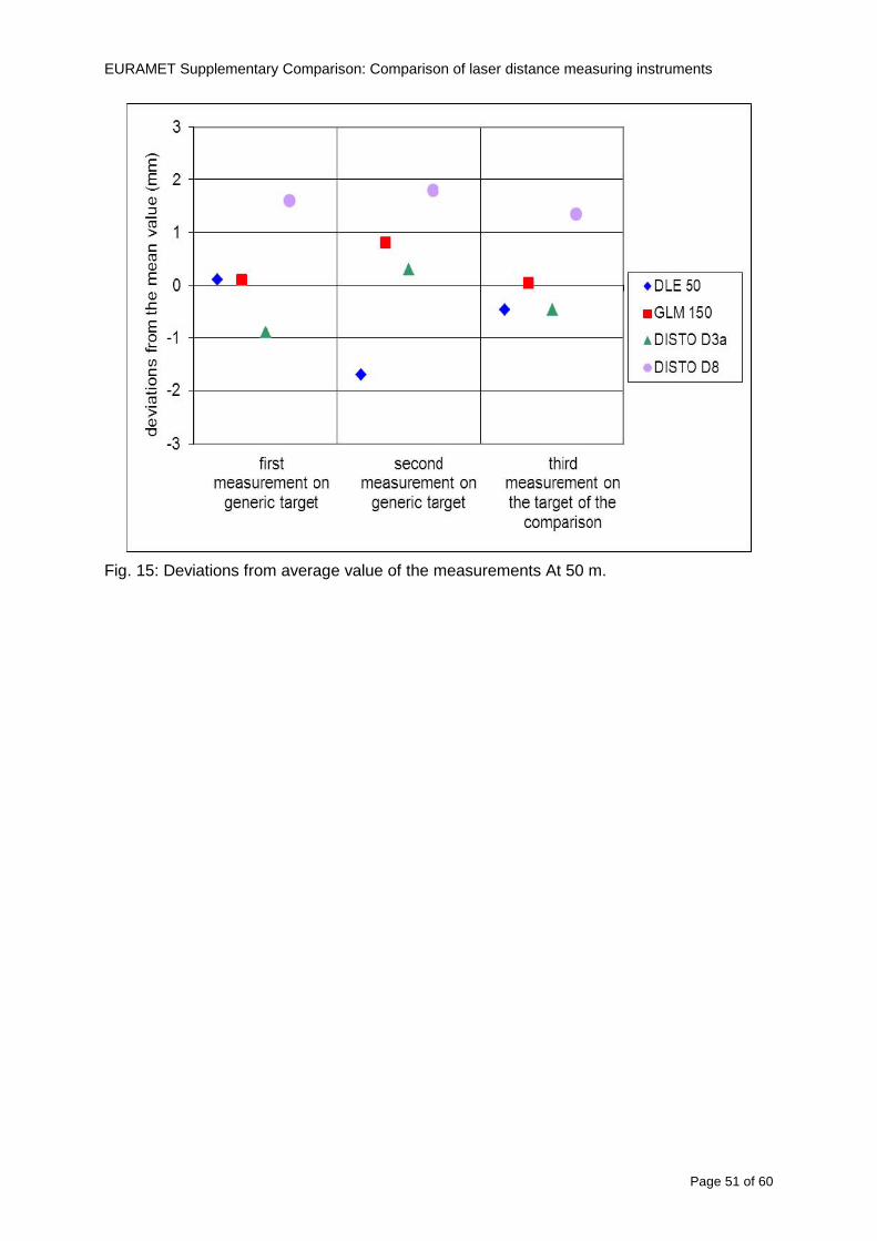
EURAMET Supplementary Comparison Comparison of laser distance measuring instruments
Page 51 of 60
Fig 15 Deviations from average value of the measurements At 50 m
EURAMET Supplementary Comparison Comparison of laser distance measuring instruments
Page 52 of 60
A19 CEM Spain
Short description of the measurement bench
To make the measurements of EDMs we have used a reference line made of adjustable supports fixed on a wall of the laboratory Each support is nominally separated five metres from the previous one so we can generate reference lengths up to fifty metres with a pitch of five metres The supports are designed to accommodate both targets and handheld EDMs Distances between supports were measured by using a total station traced to national standards The relative angles of the bases have been measured and corrected
Fig 1 - View of three consecutive supports of the 50 m baseline (left) Lab technician situating an EDM on the first support of the baseline (right)
Length measurement instrument
The baseline was calibrated by using a total station Leica TDA5005 with spherical reflector the calibration uncertainty being 02 mm for k = 2
The target is provided by the comparison The quality of the target was judged as not good due to geometrical constructive errors and the lack of rigidity and stability We measured the flatness of the target surface the distance edge-surface and the angle between them by using a 3D coordinate measuring machine The results of flatness and angle were included in the uncertainty budget and the distance EDM-target was corrected for each EDM due to each beam impinged on a different point of the target
We were not able to measure the distance 0 to 03 m because the baseline pitch is 5 meters and although we are able to measure shorter values in a different facility the target was not appropriate for our bench
EURAMET Supplementary Comparison Comparison of laser distance measuring instruments
Page 53 of 60
Fig 2 - View of an EDM on the first support of the baseline (left) A closer look showing the support adjustments and the origin plate (right)
Fig 3 - View of the comparison target on one of the supports of the baseline (left) A closer look showing the target edge against the support rigid reference (right)
Measurement method
The measurements were carried out by comparison against the known values of the calibrated baseline (metallic references on supports)
Environmental conditions were maintained within the following limits
- Temperature 20 ordmC plusmn 05 ordmC
- Humidity 45 plusmn 10
Each laser distance measuring instrument was placed at the first support of the base and aligned so that the laser beam was perpendicular to the target as indicated by the comparison protocol
For each measurement we took the average of thirty measurements It permitted us to evaluate the repeatability of the instrument
EURAMET Supplementary Comparison Comparison of laser distance measuring instruments
Page 54 of 60
A110 BEV Austria
Short description of the measurement bench
Fig 1 Carriage of tape bench View from the laser interferometer side Retroreflector mounted on the vertical plate the EDM target is mounted on the backside
Fig 2 Support for the DUT Adjustable with 2 translational and 2 rotational degrees of freedom respectively
Fig 3 Setting of the 300 mm starting position Note the rough-and-ready mounted target plate
Fig 4 Laser interferometer side of the bench The DUT is 50 m away on the other side
EURAMET Supplementary Comparison Comparison of laser distance measuring instruments
Page 55 of 60
Measurement procedure 1 The EDM is positioned with the help of a 4-axis positioning stage so that its laser beam is
coaxial with the measurement direction of the laser interferometer (in head on configuration)
2 The EDM is removed from its support The bench carriage is positioned so that the distance of the target plate from the EDM back support is 300 mm A length bar with spherical faces is used for this adjustment The laser interferometer is preset to 300 mm and the EDM is put back on its support
3 At each position 10 consecutive measurements are taken (repeatability) and the carriage is moved to the next position The carriage is manually moved under control of the laser interferometer until it is within plusmn30 microm at the correct position (Exception for the DLE 150 the target is not positioned at 10 m but at 10 m ndash 1 mm to make use of the higher resolution) The indicated (not the nominal) distance of the laser interferometer is recorded for the determination of the deviation
4 After reaching the 50 m position all points are measured in reverse order (bidirectional) Immediately after the last measurement the EDM is removed and the indication using the 300 mm length bar is checked (thus noting a possible drift of the setup)
5 Each instrument was measured 4 times according to this procedure on different days (reproducibility of bench and instrument)
Length measurement instrument
Agilent laser interferometer with long range option The bench was completed short time before performing these measurement So the characterisation was not complete and the respective measurement uncertainty of the laser interferometer is estimated rather high But anyway its contribution to the overall uncertainty can nearly be neglected
Additional remarks
The uncertainty originating from the DUT is the dominating uncertainty contribution Specifically the resolution of the two Bosch instruments (1 mm) and the repeatability are the largest contributions For the DLA 50 the pooled standard deviation of a reading at 50 m is larger than 2 mm Moreover the length dependence is not a simple function
All of the instruments show a significant deviation of the laser beam from the normal of the back (reference) face of the instrument The measured angles reach from 04deg (D3a) to 11deg (DLE 50) This leads depending on the outer dimensions of the instruments to a constant uncertainty contribution of 02 mm in our setup It must be noted that the reference faces are not well defined in most of the instruments
The reproducibility is quite different for the four instruments so only part of it originates from the setup For CMC claims we will use the standard uncertainty value of the most reproducible instrument (D3a) which amounts to 013 mm For an ideal instrument with a resolution of 01 mm and perfect repeatability we would thus have a constant expanded uncertainty of 053 mm up to 50 m
EURAMET Supplementary Comparison Comparison of laser distance measuring instruments
Page 56 of 60
A111 JV Norway
Short description of measurement bench
EDM under calibration and the reference system are aligned along a 50 m measurement bench with rails to carry the linear movement of a target plate for the EDM and a corner cube reflector for the reference system The distance between parallel axis of EDM and axis of the reference system is 130 mm Abbe error due to angle errors for the movement is smaller than 01 mm and is corrected for at each measurement point At long lengths an aperture is used approximately midway between the target plate and the EDM to avoid interfering stray light to the EDM
Alignment procedure
1) Alignment of reference system to the movement of the carriage (rails)
2) Alignment of the EDM to the movement of the carriage (rails)
3) Alignment of a plane mirror at the position of the target plate using back-reflection to the EDM output (normal incident of light on the mirror)
4) Take out the EDM and align the zero reference plate at the back of the EDM to the plane mirror
5) The mirror is replaced by the target plate and the target plate is aligned to the zero reference plate
6) Zero setting of the reference measurement system when target plate is at zero distance to the reference plate at the back of the EDM
7) Put the EDM back in position and realign it to the movement of the carriage (rails)
8) Zero setting of the EDM to the reference plate
Image 1) Image 2) Image 3) Image 4)
Image 1) Items 5) ndash 6) in alignment procedure
Fixture for HP linear interferometer is seen bottom right Part of Wyler instrument is seen to the left blue colour
Image 2) Items 7) and 8) in alignment procedure
Micrometer screws for angle alignment in two directions and linear translation for zero setting of the EDM Push button on the EDM is positioned at the tilting point of the angle adjustment table to maximize stability during measurement HP 5519 A laser head is seen to the right
Image 3) Ready to measure at selected distances from zero point the reference plate
Image 4) EDM spot size at 50 m
Length measurement instrument
- Hewlett Packard Dynamic Calibrator 5519 A (max range 80 m)
- Pressure air temperature humidity Vaisala
EURAMET Supplementary Comparison Comparison of laser distance measuring instruments
Page 57 of 60
- Digital high resolution angle measurement Wyler
I used our own target plate which is of the same type as enclosed in the artefact suitcase article number 766560 from Leica but with reduced size width x hight = 90 x 137 mm
The zero reference plate is of similar type and size
Before measurements batteries of EDMs were switched to new batteries Old batteries are switched back after calibration
For L gt 5 m an aperture of similar size as the target plate is used approximately midway between the EDM and the target plate
Additional remarks
Reports on EDM indicated values at each measurement point is the average value of n = 5 repetitions A linear model of the standard deviation for the repeatability of the EDM readings at different lengths is estimated using m = 20 repetitions at least 5 positions along the scale An estimate of the length dependent repeatability is made for each instrument
The expanded uncertainty U(95) is rounded up to the limiting resolution of 1 mm in the interval 10 m to 40 m for Bosch GLM 150
After the calibration we also estimated the angle error of the optical axis of the EDM to its back plane (back reference of EDM) Bosch DLE 50 26 mrad up measured at 50 m Bosch GLM 150 8 mrad to the left measured at 50 m Leica DISTO D3a 37 mrad down measured at 20 m Leica DISTO D8 2 mrad to the left and 4 mrad down (45 mrad total) measured at 20 m
The distance between parallel walls will be measured too large if the back plane is assumed to be normal to the optical axis of the EDM by ∆LL = (1cosα ndash 1) Bosch DLE 50 ∆LL = 340 ppm (∆L = 17 mm at L = 50 m) Bosch GLM 150 ∆LL = 32 ppm (∆L = 16 mm at L = 50 m) Leica DISTO D3a ∆LL = 7 ppm (∆L = 034 mm at L = 50 m) Leica DISTO D8 ∆LL = 10 ppm (∆L = 05 mm at L = 50 m)
EURAMET Supplementary Comparison Comparison of laser distance measuring instruments
Page 58 of 60
A112 METAS Switzerland
Short description of measurement bench (photo recom mended)
50 m bench with laser interferometer (see photo detailed description in Michel Degoumois Un Long laboratoire de mesure OFMETinfo Vol5 No 2 1998)
Length measurement instrument
HP 5529 B laser interferometer range 80 m
EURAMET Supplementary Comparison Comparison of laser distance measuring instruments
Page 59 of 60
A113 GUM Poland
Short description of measurement bench
The 50 m bench is situated in the corridor laboratory located in the basement and has its own air conditioning system with air temperature 20 plusmn 1 degC and humidity 50 plusmn 10 RH The measuring carriage is carried microscope with CCD camera and the optics associated with the interferometer The carriage is driven using belt-transmission and electrical engine with remote ndash controlled variable speed drive
The EDM was placed on the fixed adjustable plate on the other end than laser interferometer The target plate of the EDM was placed on the measuring carriage For each EDM 3 series of measurement were done Before the each measurement EDM was repositioned and aligned again
Length measurement instrument
1 Laser interferometer HP 5529A with long-range option laser head HP 5519A
2 Ambient measurement system number and location of sensors - 20 air temperature sensors type YSI with KEITHLEY multimeter they are placed very
close to axis of the laser beam - air pressure and humidity are measured with Vaisala barometer and
thermohigrometer - CO2 content was measured with analyzer made by Intelli Charge type SPN 4462
EURAMET Supplementary Comparison Comparison of laser distance measuring instruments
Page 60 of 60
Appendix 2 Corrections of reports
131 CEM Spain
CEM reported two errors in their report
1) Bosch GLM 150 EDM error for 35 m should be -08 mm instead of the indicated 08 mm
2) Leica DISTO D8 EDM error for 35 m should be -019 mm instead of the indicated 019 mm
Proposed corrections have been included in Tables 2 and 4 of the Final Report
132 AS Metrosert Estonia
AS Metrosert reported mixed up of all results for Bosch DLE 50 and Bosch GLM 150 The results and uncertainties sent for DLE 50 was results for GLM 150 and vice versa
Proposed corrections have been included in Tables 1 and 2 of the Final Report
133 INRIM Italy
Among the data reported from INRIM some anomalies were found in the measurements of BOSCH DLE 50 and LEICA DISTO D3a at distances of 20 and 25 m
After preliminary discussion on Draft A it was understood that those anomalies could be explained as a sensitivity of said instruments to the laser light that once diffused by the target is reflected by surfaces parallel to the measurement axis and detected together with the wanted signal The superimposition of the two signals can cause a ldquopullingrdquo effect leading to an overestimation of the distance being the reflected path always longer than the direct one Indeed in the INRIMrsquos set-up the target was mounted pretty close to the flat rail used for the carriage movement being likely responsible for unwanted reflections that disturbed the measurements
Since the errors reported in INRIMrsquos measurements can be ascribed to a defect of BOSCH DLE 50 and LEICA DISTO D3a andor to a lack of description of the working conditions of said instruments INRIM asked to eliminate its measurement points at 20 and 25 m of said instruments from the comparison
Proposed corrections have been included in Tables 1 and 3 of the Final Report
134 JV Norway
Justervesenet has changed the procedure and introduced two apertures instead of only one aperture (iris) which was positioned at half distance between EDM and target The reason is that the reference beam also has an aperture and it is positioned right below the beam from the EDM (130 mm distance between axes) Some diffusively reflected stray light from the EDM target might enter the aperture for the reference beam reflect at the measurement table and reach the detector of the EDM In our calibration set-up we have only seen problems at L gt 30 m We will position the first aperture at ca 5 m from the EDM and then the second aperture at ca 25 m This combination of two apertures will effectively eliminate interference of stray light from the measurement table to the EDM detector for all lengths up to 50 m
Justervesenet also increases the uncertainty component regarding repeatability reproducibility so that the expanded uncertainty increases from 14 mm to 15 mm
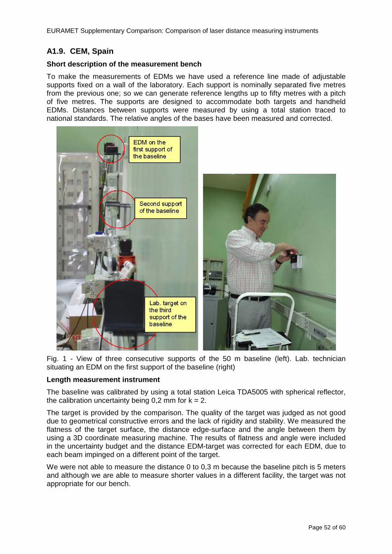
EURAMET Supplementary Comparison Comparison of laser distance measuring instruments
Page 53 of 60
Fig 2 - View of an EDM on the first support of the baseline (left) A closer look showing the support adjustments and the origin plate (right)
Fig 3 - View of the comparison target on one of the supports of the baseline (left) A closer look showing the target edge against the support rigid reference (right)
Measurement method
The measurements were carried out by comparison against the known values of the calibrated baseline (metallic references on supports)
Environmental conditions were maintained within the following limits
- Temperature 20 ordmC plusmn 05 ordmC
- Humidity 45 plusmn 10
Each laser distance measuring instrument was placed at the first support of the base and aligned so that the laser beam was perpendicular to the target as indicated by the comparison protocol
For each measurement we took the average of thirty measurements It permitted us to evaluate the repeatability of the instrument
EURAMET Supplementary Comparison Comparison of laser distance measuring instruments
Page 54 of 60
A110 BEV Austria
Short description of the measurement bench
Fig 1 Carriage of tape bench View from the laser interferometer side Retroreflector mounted on the vertical plate the EDM target is mounted on the backside
Fig 2 Support for the DUT Adjustable with 2 translational and 2 rotational degrees of freedom respectively
Fig 3 Setting of the 300 mm starting position Note the rough-and-ready mounted target plate
Fig 4 Laser interferometer side of the bench The DUT is 50 m away on the other side
EURAMET Supplementary Comparison Comparison of laser distance measuring instruments
Page 55 of 60
Measurement procedure 1 The EDM is positioned with the help of a 4-axis positioning stage so that its laser beam is
coaxial with the measurement direction of the laser interferometer (in head on configuration)
2 The EDM is removed from its support The bench carriage is positioned so that the distance of the target plate from the EDM back support is 300 mm A length bar with spherical faces is used for this adjustment The laser interferometer is preset to 300 mm and the EDM is put back on its support
3 At each position 10 consecutive measurements are taken (repeatability) and the carriage is moved to the next position The carriage is manually moved under control of the laser interferometer until it is within plusmn30 microm at the correct position (Exception for the DLE 150 the target is not positioned at 10 m but at 10 m ndash 1 mm to make use of the higher resolution) The indicated (not the nominal) distance of the laser interferometer is recorded for the determination of the deviation
4 After reaching the 50 m position all points are measured in reverse order (bidirectional) Immediately after the last measurement the EDM is removed and the indication using the 300 mm length bar is checked (thus noting a possible drift of the setup)
5 Each instrument was measured 4 times according to this procedure on different days (reproducibility of bench and instrument)
Length measurement instrument
Agilent laser interferometer with long range option The bench was completed short time before performing these measurement So the characterisation was not complete and the respective measurement uncertainty of the laser interferometer is estimated rather high But anyway its contribution to the overall uncertainty can nearly be neglected
Additional remarks
The uncertainty originating from the DUT is the dominating uncertainty contribution Specifically the resolution of the two Bosch instruments (1 mm) and the repeatability are the largest contributions For the DLA 50 the pooled standard deviation of a reading at 50 m is larger than 2 mm Moreover the length dependence is not a simple function
All of the instruments show a significant deviation of the laser beam from the normal of the back (reference) face of the instrument The measured angles reach from 04deg (D3a) to 11deg (DLE 50) This leads depending on the outer dimensions of the instruments to a constant uncertainty contribution of 02 mm in our setup It must be noted that the reference faces are not well defined in most of the instruments
The reproducibility is quite different for the four instruments so only part of it originates from the setup For CMC claims we will use the standard uncertainty value of the most reproducible instrument (D3a) which amounts to 013 mm For an ideal instrument with a resolution of 01 mm and perfect repeatability we would thus have a constant expanded uncertainty of 053 mm up to 50 m
EURAMET Supplementary Comparison Comparison of laser distance measuring instruments
Page 56 of 60
A111 JV Norway
Short description of measurement bench
EDM under calibration and the reference system are aligned along a 50 m measurement bench with rails to carry the linear movement of a target plate for the EDM and a corner cube reflector for the reference system The distance between parallel axis of EDM and axis of the reference system is 130 mm Abbe error due to angle errors for the movement is smaller than 01 mm and is corrected for at each measurement point At long lengths an aperture is used approximately midway between the target plate and the EDM to avoid interfering stray light to the EDM
Alignment procedure
1) Alignment of reference system to the movement of the carriage (rails)
2) Alignment of the EDM to the movement of the carriage (rails)
3) Alignment of a plane mirror at the position of the target plate using back-reflection to the EDM output (normal incident of light on the mirror)
4) Take out the EDM and align the zero reference plate at the back of the EDM to the plane mirror
5) The mirror is replaced by the target plate and the target plate is aligned to the zero reference plate
6) Zero setting of the reference measurement system when target plate is at zero distance to the reference plate at the back of the EDM
7) Put the EDM back in position and realign it to the movement of the carriage (rails)
8) Zero setting of the EDM to the reference plate
Image 1) Image 2) Image 3) Image 4)
Image 1) Items 5) ndash 6) in alignment procedure
Fixture for HP linear interferometer is seen bottom right Part of Wyler instrument is seen to the left blue colour
Image 2) Items 7) and 8) in alignment procedure
Micrometer screws for angle alignment in two directions and linear translation for zero setting of the EDM Push button on the EDM is positioned at the tilting point of the angle adjustment table to maximize stability during measurement HP 5519 A laser head is seen to the right
Image 3) Ready to measure at selected distances from zero point the reference plate
Image 4) EDM spot size at 50 m
Length measurement instrument
- Hewlett Packard Dynamic Calibrator 5519 A (max range 80 m)
- Pressure air temperature humidity Vaisala
EURAMET Supplementary Comparison Comparison of laser distance measuring instruments
Page 57 of 60
- Digital high resolution angle measurement Wyler
I used our own target plate which is of the same type as enclosed in the artefact suitcase article number 766560 from Leica but with reduced size width x hight = 90 x 137 mm
The zero reference plate is of similar type and size
Before measurements batteries of EDMs were switched to new batteries Old batteries are switched back after calibration
For L gt 5 m an aperture of similar size as the target plate is used approximately midway between the EDM and the target plate
Additional remarks
Reports on EDM indicated values at each measurement point is the average value of n = 5 repetitions A linear model of the standard deviation for the repeatability of the EDM readings at different lengths is estimated using m = 20 repetitions at least 5 positions along the scale An estimate of the length dependent repeatability is made for each instrument
The expanded uncertainty U(95) is rounded up to the limiting resolution of 1 mm in the interval 10 m to 40 m for Bosch GLM 150
After the calibration we also estimated the angle error of the optical axis of the EDM to its back plane (back reference of EDM) Bosch DLE 50 26 mrad up measured at 50 m Bosch GLM 150 8 mrad to the left measured at 50 m Leica DISTO D3a 37 mrad down measured at 20 m Leica DISTO D8 2 mrad to the left and 4 mrad down (45 mrad total) measured at 20 m
The distance between parallel walls will be measured too large if the back plane is assumed to be normal to the optical axis of the EDM by ∆LL = (1cosα ndash 1) Bosch DLE 50 ∆LL = 340 ppm (∆L = 17 mm at L = 50 m) Bosch GLM 150 ∆LL = 32 ppm (∆L = 16 mm at L = 50 m) Leica DISTO D3a ∆LL = 7 ppm (∆L = 034 mm at L = 50 m) Leica DISTO D8 ∆LL = 10 ppm (∆L = 05 mm at L = 50 m)
EURAMET Supplementary Comparison Comparison of laser distance measuring instruments
Page 58 of 60
A112 METAS Switzerland
Short description of measurement bench (photo recom mended)
50 m bench with laser interferometer (see photo detailed description in Michel Degoumois Un Long laboratoire de mesure OFMETinfo Vol5 No 2 1998)
Length measurement instrument
HP 5529 B laser interferometer range 80 m
EURAMET Supplementary Comparison Comparison of laser distance measuring instruments
Page 59 of 60
A113 GUM Poland
Short description of measurement bench
The 50 m bench is situated in the corridor laboratory located in the basement and has its own air conditioning system with air temperature 20 plusmn 1 degC and humidity 50 plusmn 10 RH The measuring carriage is carried microscope with CCD camera and the optics associated with the interferometer The carriage is driven using belt-transmission and electrical engine with remote ndash controlled variable speed drive
The EDM was placed on the fixed adjustable plate on the other end than laser interferometer The target plate of the EDM was placed on the measuring carriage For each EDM 3 series of measurement were done Before the each measurement EDM was repositioned and aligned again
Length measurement instrument
1 Laser interferometer HP 5529A with long-range option laser head HP 5519A
2 Ambient measurement system number and location of sensors - 20 air temperature sensors type YSI with KEITHLEY multimeter they are placed very
close to axis of the laser beam - air pressure and humidity are measured with Vaisala barometer and
thermohigrometer - CO2 content was measured with analyzer made by Intelli Charge type SPN 4462
EURAMET Supplementary Comparison Comparison of laser distance measuring instruments
Page 60 of 60
Appendix 2 Corrections of reports
131 CEM Spain
CEM reported two errors in their report
1) Bosch GLM 150 EDM error for 35 m should be -08 mm instead of the indicated 08 mm
2) Leica DISTO D8 EDM error for 35 m should be -019 mm instead of the indicated 019 mm
Proposed corrections have been included in Tables 2 and 4 of the Final Report
132 AS Metrosert Estonia
AS Metrosert reported mixed up of all results for Bosch DLE 50 and Bosch GLM 150 The results and uncertainties sent for DLE 50 was results for GLM 150 and vice versa
Proposed corrections have been included in Tables 1 and 2 of the Final Report
133 INRIM Italy
Among the data reported from INRIM some anomalies were found in the measurements of BOSCH DLE 50 and LEICA DISTO D3a at distances of 20 and 25 m
After preliminary discussion on Draft A it was understood that those anomalies could be explained as a sensitivity of said instruments to the laser light that once diffused by the target is reflected by surfaces parallel to the measurement axis and detected together with the wanted signal The superimposition of the two signals can cause a ldquopullingrdquo effect leading to an overestimation of the distance being the reflected path always longer than the direct one Indeed in the INRIMrsquos set-up the target was mounted pretty close to the flat rail used for the carriage movement being likely responsible for unwanted reflections that disturbed the measurements
Since the errors reported in INRIMrsquos measurements can be ascribed to a defect of BOSCH DLE 50 and LEICA DISTO D3a andor to a lack of description of the working conditions of said instruments INRIM asked to eliminate its measurement points at 20 and 25 m of said instruments from the comparison
Proposed corrections have been included in Tables 1 and 3 of the Final Report
134 JV Norway
Justervesenet has changed the procedure and introduced two apertures instead of only one aperture (iris) which was positioned at half distance between EDM and target The reason is that the reference beam also has an aperture and it is positioned right below the beam from the EDM (130 mm distance between axes) Some diffusively reflected stray light from the EDM target might enter the aperture for the reference beam reflect at the measurement table and reach the detector of the EDM In our calibration set-up we have only seen problems at L gt 30 m We will position the first aperture at ca 5 m from the EDM and then the second aperture at ca 25 m This combination of two apertures will effectively eliminate interference of stray light from the measurement table to the EDM detector for all lengths up to 50 m
Justervesenet also increases the uncertainty component regarding repeatability reproducibility so that the expanded uncertainty increases from 14 mm to 15 mm
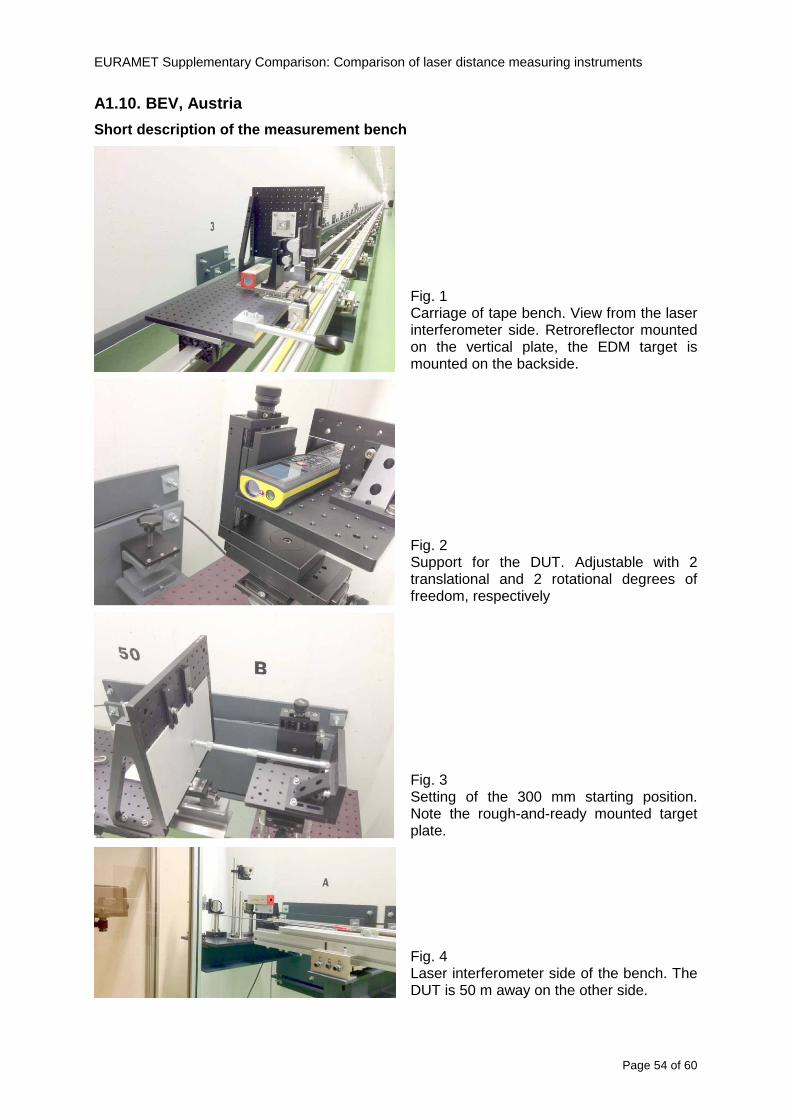
EURAMET Supplementary Comparison Comparison of laser distance measuring instruments
Page 54 of 60
A110 BEV Austria
Short description of the measurement bench
Fig 1 Carriage of tape bench View from the laser interferometer side Retroreflector mounted on the vertical plate the EDM target is mounted on the backside
Fig 2 Support for the DUT Adjustable with 2 translational and 2 rotational degrees of freedom respectively
Fig 3 Setting of the 300 mm starting position Note the rough-and-ready mounted target plate
Fig 4 Laser interferometer side of the bench The DUT is 50 m away on the other side
EURAMET Supplementary Comparison Comparison of laser distance measuring instruments
Page 55 of 60
Measurement procedure 1 The EDM is positioned with the help of a 4-axis positioning stage so that its laser beam is
coaxial with the measurement direction of the laser interferometer (in head on configuration)
2 The EDM is removed from its support The bench carriage is positioned so that the distance of the target plate from the EDM back support is 300 mm A length bar with spherical faces is used for this adjustment The laser interferometer is preset to 300 mm and the EDM is put back on its support
3 At each position 10 consecutive measurements are taken (repeatability) and the carriage is moved to the next position The carriage is manually moved under control of the laser interferometer until it is within plusmn30 microm at the correct position (Exception for the DLE 150 the target is not positioned at 10 m but at 10 m ndash 1 mm to make use of the higher resolution) The indicated (not the nominal) distance of the laser interferometer is recorded for the determination of the deviation
4 After reaching the 50 m position all points are measured in reverse order (bidirectional) Immediately after the last measurement the EDM is removed and the indication using the 300 mm length bar is checked (thus noting a possible drift of the setup)
5 Each instrument was measured 4 times according to this procedure on different days (reproducibility of bench and instrument)
Length measurement instrument
Agilent laser interferometer with long range option The bench was completed short time before performing these measurement So the characterisation was not complete and the respective measurement uncertainty of the laser interferometer is estimated rather high But anyway its contribution to the overall uncertainty can nearly be neglected
Additional remarks
The uncertainty originating from the DUT is the dominating uncertainty contribution Specifically the resolution of the two Bosch instruments (1 mm) and the repeatability are the largest contributions For the DLA 50 the pooled standard deviation of a reading at 50 m is larger than 2 mm Moreover the length dependence is not a simple function
All of the instruments show a significant deviation of the laser beam from the normal of the back (reference) face of the instrument The measured angles reach from 04deg (D3a) to 11deg (DLE 50) This leads depending on the outer dimensions of the instruments to a constant uncertainty contribution of 02 mm in our setup It must be noted that the reference faces are not well defined in most of the instruments
The reproducibility is quite different for the four instruments so only part of it originates from the setup For CMC claims we will use the standard uncertainty value of the most reproducible instrument (D3a) which amounts to 013 mm For an ideal instrument with a resolution of 01 mm and perfect repeatability we would thus have a constant expanded uncertainty of 053 mm up to 50 m
EURAMET Supplementary Comparison Comparison of laser distance measuring instruments
Page 56 of 60
A111 JV Norway
Short description of measurement bench
EDM under calibration and the reference system are aligned along a 50 m measurement bench with rails to carry the linear movement of a target plate for the EDM and a corner cube reflector for the reference system The distance between parallel axis of EDM and axis of the reference system is 130 mm Abbe error due to angle errors for the movement is smaller than 01 mm and is corrected for at each measurement point At long lengths an aperture is used approximately midway between the target plate and the EDM to avoid interfering stray light to the EDM
Alignment procedure
1) Alignment of reference system to the movement of the carriage (rails)
2) Alignment of the EDM to the movement of the carriage (rails)
3) Alignment of a plane mirror at the position of the target plate using back-reflection to the EDM output (normal incident of light on the mirror)
4) Take out the EDM and align the zero reference plate at the back of the EDM to the plane mirror
5) The mirror is replaced by the target plate and the target plate is aligned to the zero reference plate
6) Zero setting of the reference measurement system when target plate is at zero distance to the reference plate at the back of the EDM
7) Put the EDM back in position and realign it to the movement of the carriage (rails)
8) Zero setting of the EDM to the reference plate
Image 1) Image 2) Image 3) Image 4)
Image 1) Items 5) ndash 6) in alignment procedure
Fixture for HP linear interferometer is seen bottom right Part of Wyler instrument is seen to the left blue colour
Image 2) Items 7) and 8) in alignment procedure
Micrometer screws for angle alignment in two directions and linear translation for zero setting of the EDM Push button on the EDM is positioned at the tilting point of the angle adjustment table to maximize stability during measurement HP 5519 A laser head is seen to the right
Image 3) Ready to measure at selected distances from zero point the reference plate
Image 4) EDM spot size at 50 m
Length measurement instrument
- Hewlett Packard Dynamic Calibrator 5519 A (max range 80 m)
- Pressure air temperature humidity Vaisala
EURAMET Supplementary Comparison Comparison of laser distance measuring instruments
Page 57 of 60
- Digital high resolution angle measurement Wyler
I used our own target plate which is of the same type as enclosed in the artefact suitcase article number 766560 from Leica but with reduced size width x hight = 90 x 137 mm
The zero reference plate is of similar type and size
Before measurements batteries of EDMs were switched to new batteries Old batteries are switched back after calibration
For L gt 5 m an aperture of similar size as the target plate is used approximately midway between the EDM and the target plate
Additional remarks
Reports on EDM indicated values at each measurement point is the average value of n = 5 repetitions A linear model of the standard deviation for the repeatability of the EDM readings at different lengths is estimated using m = 20 repetitions at least 5 positions along the scale An estimate of the length dependent repeatability is made for each instrument
The expanded uncertainty U(95) is rounded up to the limiting resolution of 1 mm in the interval 10 m to 40 m for Bosch GLM 150
After the calibration we also estimated the angle error of the optical axis of the EDM to its back plane (back reference of EDM) Bosch DLE 50 26 mrad up measured at 50 m Bosch GLM 150 8 mrad to the left measured at 50 m Leica DISTO D3a 37 mrad down measured at 20 m Leica DISTO D8 2 mrad to the left and 4 mrad down (45 mrad total) measured at 20 m
The distance between parallel walls will be measured too large if the back plane is assumed to be normal to the optical axis of the EDM by ∆LL = (1cosα ndash 1) Bosch DLE 50 ∆LL = 340 ppm (∆L = 17 mm at L = 50 m) Bosch GLM 150 ∆LL = 32 ppm (∆L = 16 mm at L = 50 m) Leica DISTO D3a ∆LL = 7 ppm (∆L = 034 mm at L = 50 m) Leica DISTO D8 ∆LL = 10 ppm (∆L = 05 mm at L = 50 m)
EURAMET Supplementary Comparison Comparison of laser distance measuring instruments
Page 58 of 60
A112 METAS Switzerland
Short description of measurement bench (photo recom mended)
50 m bench with laser interferometer (see photo detailed description in Michel Degoumois Un Long laboratoire de mesure OFMETinfo Vol5 No 2 1998)
Length measurement instrument
HP 5529 B laser interferometer range 80 m
EURAMET Supplementary Comparison Comparison of laser distance measuring instruments
Page 59 of 60
A113 GUM Poland
Short description of measurement bench
The 50 m bench is situated in the corridor laboratory located in the basement and has its own air conditioning system with air temperature 20 plusmn 1 degC and humidity 50 plusmn 10 RH The measuring carriage is carried microscope with CCD camera and the optics associated with the interferometer The carriage is driven using belt-transmission and electrical engine with remote ndash controlled variable speed drive
The EDM was placed on the fixed adjustable plate on the other end than laser interferometer The target plate of the EDM was placed on the measuring carriage For each EDM 3 series of measurement were done Before the each measurement EDM was repositioned and aligned again
Length measurement instrument
1 Laser interferometer HP 5529A with long-range option laser head HP 5519A
2 Ambient measurement system number and location of sensors - 20 air temperature sensors type YSI with KEITHLEY multimeter they are placed very
close to axis of the laser beam - air pressure and humidity are measured with Vaisala barometer and
thermohigrometer - CO2 content was measured with analyzer made by Intelli Charge type SPN 4462
EURAMET Supplementary Comparison Comparison of laser distance measuring instruments
Page 60 of 60
Appendix 2 Corrections of reports
131 CEM Spain
CEM reported two errors in their report
1) Bosch GLM 150 EDM error for 35 m should be -08 mm instead of the indicated 08 mm
2) Leica DISTO D8 EDM error for 35 m should be -019 mm instead of the indicated 019 mm
Proposed corrections have been included in Tables 2 and 4 of the Final Report
132 AS Metrosert Estonia
AS Metrosert reported mixed up of all results for Bosch DLE 50 and Bosch GLM 150 The results and uncertainties sent for DLE 50 was results for GLM 150 and vice versa
Proposed corrections have been included in Tables 1 and 2 of the Final Report
133 INRIM Italy
Among the data reported from INRIM some anomalies were found in the measurements of BOSCH DLE 50 and LEICA DISTO D3a at distances of 20 and 25 m
After preliminary discussion on Draft A it was understood that those anomalies could be explained as a sensitivity of said instruments to the laser light that once diffused by the target is reflected by surfaces parallel to the measurement axis and detected together with the wanted signal The superimposition of the two signals can cause a ldquopullingrdquo effect leading to an overestimation of the distance being the reflected path always longer than the direct one Indeed in the INRIMrsquos set-up the target was mounted pretty close to the flat rail used for the carriage movement being likely responsible for unwanted reflections that disturbed the measurements
Since the errors reported in INRIMrsquos measurements can be ascribed to a defect of BOSCH DLE 50 and LEICA DISTO D3a andor to a lack of description of the working conditions of said instruments INRIM asked to eliminate its measurement points at 20 and 25 m of said instruments from the comparison
Proposed corrections have been included in Tables 1 and 3 of the Final Report
134 JV Norway
Justervesenet has changed the procedure and introduced two apertures instead of only one aperture (iris) which was positioned at half distance between EDM and target The reason is that the reference beam also has an aperture and it is positioned right below the beam from the EDM (130 mm distance between axes) Some diffusively reflected stray light from the EDM target might enter the aperture for the reference beam reflect at the measurement table and reach the detector of the EDM In our calibration set-up we have only seen problems at L gt 30 m We will position the first aperture at ca 5 m from the EDM and then the second aperture at ca 25 m This combination of two apertures will effectively eliminate interference of stray light from the measurement table to the EDM detector for all lengths up to 50 m
Justervesenet also increases the uncertainty component regarding repeatability reproducibility so that the expanded uncertainty increases from 14 mm to 15 mm
EURAMET Supplementary Comparison Comparison of laser distance measuring instruments
Page 55 of 60
Measurement procedure 1 The EDM is positioned with the help of a 4-axis positioning stage so that its laser beam is
coaxial with the measurement direction of the laser interferometer (in head on configuration)
2 The EDM is removed from its support The bench carriage is positioned so that the distance of the target plate from the EDM back support is 300 mm A length bar with spherical faces is used for this adjustment The laser interferometer is preset to 300 mm and the EDM is put back on its support
3 At each position 10 consecutive measurements are taken (repeatability) and the carriage is moved to the next position The carriage is manually moved under control of the laser interferometer until it is within plusmn30 microm at the correct position (Exception for the DLE 150 the target is not positioned at 10 m but at 10 m ndash 1 mm to make use of the higher resolution) The indicated (not the nominal) distance of the laser interferometer is recorded for the determination of the deviation
4 After reaching the 50 m position all points are measured in reverse order (bidirectional) Immediately after the last measurement the EDM is removed and the indication using the 300 mm length bar is checked (thus noting a possible drift of the setup)
5 Each instrument was measured 4 times according to this procedure on different days (reproducibility of bench and instrument)
Length measurement instrument
Agilent laser interferometer with long range option The bench was completed short time before performing these measurement So the characterisation was not complete and the respective measurement uncertainty of the laser interferometer is estimated rather high But anyway its contribution to the overall uncertainty can nearly be neglected
Additional remarks
The uncertainty originating from the DUT is the dominating uncertainty contribution Specifically the resolution of the two Bosch instruments (1 mm) and the repeatability are the largest contributions For the DLA 50 the pooled standard deviation of a reading at 50 m is larger than 2 mm Moreover the length dependence is not a simple function
All of the instruments show a significant deviation of the laser beam from the normal of the back (reference) face of the instrument The measured angles reach from 04deg (D3a) to 11deg (DLE 50) This leads depending on the outer dimensions of the instruments to a constant uncertainty contribution of 02 mm in our setup It must be noted that the reference faces are not well defined in most of the instruments
The reproducibility is quite different for the four instruments so only part of it originates from the setup For CMC claims we will use the standard uncertainty value of the most reproducible instrument (D3a) which amounts to 013 mm For an ideal instrument with a resolution of 01 mm and perfect repeatability we would thus have a constant expanded uncertainty of 053 mm up to 50 m
EURAMET Supplementary Comparison Comparison of laser distance measuring instruments
Page 56 of 60
A111 JV Norway
Short description of measurement bench
EDM under calibration and the reference system are aligned along a 50 m measurement bench with rails to carry the linear movement of a target plate for the EDM and a corner cube reflector for the reference system The distance between parallel axis of EDM and axis of the reference system is 130 mm Abbe error due to angle errors for the movement is smaller than 01 mm and is corrected for at each measurement point At long lengths an aperture is used approximately midway between the target plate and the EDM to avoid interfering stray light to the EDM
Alignment procedure
1) Alignment of reference system to the movement of the carriage (rails)
2) Alignment of the EDM to the movement of the carriage (rails)
3) Alignment of a plane mirror at the position of the target plate using back-reflection to the EDM output (normal incident of light on the mirror)
4) Take out the EDM and align the zero reference plate at the back of the EDM to the plane mirror
5) The mirror is replaced by the target plate and the target plate is aligned to the zero reference plate
6) Zero setting of the reference measurement system when target plate is at zero distance to the reference plate at the back of the EDM
7) Put the EDM back in position and realign it to the movement of the carriage (rails)
8) Zero setting of the EDM to the reference plate
Image 1) Image 2) Image 3) Image 4)
Image 1) Items 5) ndash 6) in alignment procedure
Fixture for HP linear interferometer is seen bottom right Part of Wyler instrument is seen to the left blue colour
Image 2) Items 7) and 8) in alignment procedure
Micrometer screws for angle alignment in two directions and linear translation for zero setting of the EDM Push button on the EDM is positioned at the tilting point of the angle adjustment table to maximize stability during measurement HP 5519 A laser head is seen to the right
Image 3) Ready to measure at selected distances from zero point the reference plate
Image 4) EDM spot size at 50 m
Length measurement instrument
- Hewlett Packard Dynamic Calibrator 5519 A (max range 80 m)
- Pressure air temperature humidity Vaisala
EURAMET Supplementary Comparison Comparison of laser distance measuring instruments
Page 57 of 60
- Digital high resolution angle measurement Wyler
I used our own target plate which is of the same type as enclosed in the artefact suitcase article number 766560 from Leica but with reduced size width x hight = 90 x 137 mm
The zero reference plate is of similar type and size
Before measurements batteries of EDMs were switched to new batteries Old batteries are switched back after calibration
For L gt 5 m an aperture of similar size as the target plate is used approximately midway between the EDM and the target plate
Additional remarks
Reports on EDM indicated values at each measurement point is the average value of n = 5 repetitions A linear model of the standard deviation for the repeatability of the EDM readings at different lengths is estimated using m = 20 repetitions at least 5 positions along the scale An estimate of the length dependent repeatability is made for each instrument
The expanded uncertainty U(95) is rounded up to the limiting resolution of 1 mm in the interval 10 m to 40 m for Bosch GLM 150
After the calibration we also estimated the angle error of the optical axis of the EDM to its back plane (back reference of EDM) Bosch DLE 50 26 mrad up measured at 50 m Bosch GLM 150 8 mrad to the left measured at 50 m Leica DISTO D3a 37 mrad down measured at 20 m Leica DISTO D8 2 mrad to the left and 4 mrad down (45 mrad total) measured at 20 m
The distance between parallel walls will be measured too large if the back plane is assumed to be normal to the optical axis of the EDM by ∆LL = (1cosα ndash 1) Bosch DLE 50 ∆LL = 340 ppm (∆L = 17 mm at L = 50 m) Bosch GLM 150 ∆LL = 32 ppm (∆L = 16 mm at L = 50 m) Leica DISTO D3a ∆LL = 7 ppm (∆L = 034 mm at L = 50 m) Leica DISTO D8 ∆LL = 10 ppm (∆L = 05 mm at L = 50 m)
EURAMET Supplementary Comparison Comparison of laser distance measuring instruments
Page 58 of 60
A112 METAS Switzerland
Short description of measurement bench (photo recom mended)
50 m bench with laser interferometer (see photo detailed description in Michel Degoumois Un Long laboratoire de mesure OFMETinfo Vol5 No 2 1998)
Length measurement instrument
HP 5529 B laser interferometer range 80 m
EURAMET Supplementary Comparison Comparison of laser distance measuring instruments
Page 59 of 60
A113 GUM Poland
Short description of measurement bench
The 50 m bench is situated in the corridor laboratory located in the basement and has its own air conditioning system with air temperature 20 plusmn 1 degC and humidity 50 plusmn 10 RH The measuring carriage is carried microscope with CCD camera and the optics associated with the interferometer The carriage is driven using belt-transmission and electrical engine with remote ndash controlled variable speed drive
The EDM was placed on the fixed adjustable plate on the other end than laser interferometer The target plate of the EDM was placed on the measuring carriage For each EDM 3 series of measurement were done Before the each measurement EDM was repositioned and aligned again
Length measurement instrument
1 Laser interferometer HP 5529A with long-range option laser head HP 5519A
2 Ambient measurement system number and location of sensors - 20 air temperature sensors type YSI with KEITHLEY multimeter they are placed very
close to axis of the laser beam - air pressure and humidity are measured with Vaisala barometer and
thermohigrometer - CO2 content was measured with analyzer made by Intelli Charge type SPN 4462
EURAMET Supplementary Comparison Comparison of laser distance measuring instruments
Page 60 of 60
Appendix 2 Corrections of reports
131 CEM Spain
CEM reported two errors in their report
1) Bosch GLM 150 EDM error for 35 m should be -08 mm instead of the indicated 08 mm
2) Leica DISTO D8 EDM error for 35 m should be -019 mm instead of the indicated 019 mm
Proposed corrections have been included in Tables 2 and 4 of the Final Report
132 AS Metrosert Estonia
AS Metrosert reported mixed up of all results for Bosch DLE 50 and Bosch GLM 150 The results and uncertainties sent for DLE 50 was results for GLM 150 and vice versa
Proposed corrections have been included in Tables 1 and 2 of the Final Report
133 INRIM Italy
Among the data reported from INRIM some anomalies were found in the measurements of BOSCH DLE 50 and LEICA DISTO D3a at distances of 20 and 25 m
After preliminary discussion on Draft A it was understood that those anomalies could be explained as a sensitivity of said instruments to the laser light that once diffused by the target is reflected by surfaces parallel to the measurement axis and detected together with the wanted signal The superimposition of the two signals can cause a ldquopullingrdquo effect leading to an overestimation of the distance being the reflected path always longer than the direct one Indeed in the INRIMrsquos set-up the target was mounted pretty close to the flat rail used for the carriage movement being likely responsible for unwanted reflections that disturbed the measurements
Since the errors reported in INRIMrsquos measurements can be ascribed to a defect of BOSCH DLE 50 and LEICA DISTO D3a andor to a lack of description of the working conditions of said instruments INRIM asked to eliminate its measurement points at 20 and 25 m of said instruments from the comparison
Proposed corrections have been included in Tables 1 and 3 of the Final Report
134 JV Norway
Justervesenet has changed the procedure and introduced two apertures instead of only one aperture (iris) which was positioned at half distance between EDM and target The reason is that the reference beam also has an aperture and it is positioned right below the beam from the EDM (130 mm distance between axes) Some diffusively reflected stray light from the EDM target might enter the aperture for the reference beam reflect at the measurement table and reach the detector of the EDM In our calibration set-up we have only seen problems at L gt 30 m We will position the first aperture at ca 5 m from the EDM and then the second aperture at ca 25 m This combination of two apertures will effectively eliminate interference of stray light from the measurement table to the EDM detector for all lengths up to 50 m
Justervesenet also increases the uncertainty component regarding repeatability reproducibility so that the expanded uncertainty increases from 14 mm to 15 mm

EURAMET Supplementary Comparison Comparison of laser distance measuring instruments
Page 57 of 60
- Digital high resolution angle measurement Wyler
I used our own target plate which is of the same type as enclosed in the artefact suitcase article number 766560 from Leica but with reduced size width x hight = 90 x 137 mm
The zero reference plate is of similar type and size
Before measurements batteries of EDMs were switched to new batteries Old batteries are switched back after calibration
For L gt 5 m an aperture of similar size as the target plate is used approximately midway between the EDM and the target plate
Additional remarks
Reports on EDM indicated values at each measurement point is the average value of n = 5 repetitions A linear model of the standard deviation for the repeatability of the EDM readings at different lengths is estimated using m = 20 repetitions at least 5 positions along the scale An estimate of the length dependent repeatability is made for each instrument
The expanded uncertainty U(95) is rounded up to the limiting resolution of 1 mm in the interval 10 m to 40 m for Bosch GLM 150
After the calibration we also estimated the angle error of the optical axis of the EDM to its back plane (back reference of EDM) Bosch DLE 50 26 mrad up measured at 50 m Bosch GLM 150 8 mrad to the left measured at 50 m Leica DISTO D3a 37 mrad down measured at 20 m Leica DISTO D8 2 mrad to the left and 4 mrad down (45 mrad total) measured at 20 m
The distance between parallel walls will be measured too large if the back plane is assumed to be normal to the optical axis of the EDM by ∆LL = (1cosα ndash 1) Bosch DLE 50 ∆LL = 340 ppm (∆L = 17 mm at L = 50 m) Bosch GLM 150 ∆LL = 32 ppm (∆L = 16 mm at L = 50 m) Leica DISTO D3a ∆LL = 7 ppm (∆L = 034 mm at L = 50 m) Leica DISTO D8 ∆LL = 10 ppm (∆L = 05 mm at L = 50 m)
EURAMET Supplementary Comparison Comparison of laser distance measuring instruments
Page 58 of 60
A112 METAS Switzerland
Short description of measurement bench (photo recom mended)
50 m bench with laser interferometer (see photo detailed description in Michel Degoumois Un Long laboratoire de mesure OFMETinfo Vol5 No 2 1998)
Length measurement instrument
HP 5529 B laser interferometer range 80 m
EURAMET Supplementary Comparison Comparison of laser distance measuring instruments
Page 59 of 60
A113 GUM Poland
Short description of measurement bench
The 50 m bench is situated in the corridor laboratory located in the basement and has its own air conditioning system with air temperature 20 plusmn 1 degC and humidity 50 plusmn 10 RH The measuring carriage is carried microscope with CCD camera and the optics associated with the interferometer The carriage is driven using belt-transmission and electrical engine with remote ndash controlled variable speed drive
The EDM was placed on the fixed adjustable plate on the other end than laser interferometer The target plate of the EDM was placed on the measuring carriage For each EDM 3 series of measurement were done Before the each measurement EDM was repositioned and aligned again
Length measurement instrument
1 Laser interferometer HP 5529A with long-range option laser head HP 5519A
2 Ambient measurement system number and location of sensors - 20 air temperature sensors type YSI with KEITHLEY multimeter they are placed very
close to axis of the laser beam - air pressure and humidity are measured with Vaisala barometer and
thermohigrometer - CO2 content was measured with analyzer made by Intelli Charge type SPN 4462
EURAMET Supplementary Comparison Comparison of laser distance measuring instruments
Page 60 of 60
Appendix 2 Corrections of reports
131 CEM Spain
CEM reported two errors in their report
1) Bosch GLM 150 EDM error for 35 m should be -08 mm instead of the indicated 08 mm
2) Leica DISTO D8 EDM error for 35 m should be -019 mm instead of the indicated 019 mm
Proposed corrections have been included in Tables 2 and 4 of the Final Report
132 AS Metrosert Estonia
AS Metrosert reported mixed up of all results for Bosch DLE 50 and Bosch GLM 150 The results and uncertainties sent for DLE 50 was results for GLM 150 and vice versa
Proposed corrections have been included in Tables 1 and 2 of the Final Report
133 INRIM Italy
Among the data reported from INRIM some anomalies were found in the measurements of BOSCH DLE 50 and LEICA DISTO D3a at distances of 20 and 25 m
After preliminary discussion on Draft A it was understood that those anomalies could be explained as a sensitivity of said instruments to the laser light that once diffused by the target is reflected by surfaces parallel to the measurement axis and detected together with the wanted signal The superimposition of the two signals can cause a ldquopullingrdquo effect leading to an overestimation of the distance being the reflected path always longer than the direct one Indeed in the INRIMrsquos set-up the target was mounted pretty close to the flat rail used for the carriage movement being likely responsible for unwanted reflections that disturbed the measurements
Since the errors reported in INRIMrsquos measurements can be ascribed to a defect of BOSCH DLE 50 and LEICA DISTO D3a andor to a lack of description of the working conditions of said instruments INRIM asked to eliminate its measurement points at 20 and 25 m of said instruments from the comparison
Proposed corrections have been included in Tables 1 and 3 of the Final Report
134 JV Norway
Justervesenet has changed the procedure and introduced two apertures instead of only one aperture (iris) which was positioned at half distance between EDM and target The reason is that the reference beam also has an aperture and it is positioned right below the beam from the EDM (130 mm distance between axes) Some diffusively reflected stray light from the EDM target might enter the aperture for the reference beam reflect at the measurement table and reach the detector of the EDM In our calibration set-up we have only seen problems at L gt 30 m We will position the first aperture at ca 5 m from the EDM and then the second aperture at ca 25 m This combination of two apertures will effectively eliminate interference of stray light from the measurement table to the EDM detector for all lengths up to 50 m
Justervesenet also increases the uncertainty component regarding repeatability reproducibility so that the expanded uncertainty increases from 14 mm to 15 mm
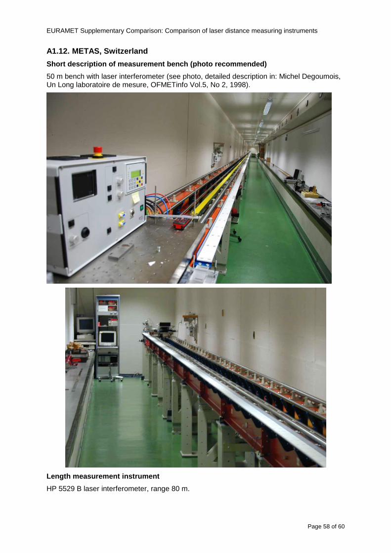
EURAMET Supplementary Comparison Comparison of laser distance measuring instruments
Page 58 of 60
A112 METAS Switzerland
Short description of measurement bench (photo recom mended)
50 m bench with laser interferometer (see photo detailed description in Michel Degoumois Un Long laboratoire de mesure OFMETinfo Vol5 No 2 1998)
Length measurement instrument
HP 5529 B laser interferometer range 80 m
EURAMET Supplementary Comparison Comparison of laser distance measuring instruments
Page 59 of 60
A113 GUM Poland
Short description of measurement bench
The 50 m bench is situated in the corridor laboratory located in the basement and has its own air conditioning system with air temperature 20 plusmn 1 degC and humidity 50 plusmn 10 RH The measuring carriage is carried microscope with CCD camera and the optics associated with the interferometer The carriage is driven using belt-transmission and electrical engine with remote ndash controlled variable speed drive
The EDM was placed on the fixed adjustable plate on the other end than laser interferometer The target plate of the EDM was placed on the measuring carriage For each EDM 3 series of measurement were done Before the each measurement EDM was repositioned and aligned again
Length measurement instrument
1 Laser interferometer HP 5529A with long-range option laser head HP 5519A
2 Ambient measurement system number and location of sensors - 20 air temperature sensors type YSI with KEITHLEY multimeter they are placed very
close to axis of the laser beam - air pressure and humidity are measured with Vaisala barometer and
thermohigrometer - CO2 content was measured with analyzer made by Intelli Charge type SPN 4462
EURAMET Supplementary Comparison Comparison of laser distance measuring instruments
Page 60 of 60
Appendix 2 Corrections of reports
131 CEM Spain
CEM reported two errors in their report
1) Bosch GLM 150 EDM error for 35 m should be -08 mm instead of the indicated 08 mm
2) Leica DISTO D8 EDM error for 35 m should be -019 mm instead of the indicated 019 mm
Proposed corrections have been included in Tables 2 and 4 of the Final Report
132 AS Metrosert Estonia
AS Metrosert reported mixed up of all results for Bosch DLE 50 and Bosch GLM 150 The results and uncertainties sent for DLE 50 was results for GLM 150 and vice versa
Proposed corrections have been included in Tables 1 and 2 of the Final Report
133 INRIM Italy
Among the data reported from INRIM some anomalies were found in the measurements of BOSCH DLE 50 and LEICA DISTO D3a at distances of 20 and 25 m
After preliminary discussion on Draft A it was understood that those anomalies could be explained as a sensitivity of said instruments to the laser light that once diffused by the target is reflected by surfaces parallel to the measurement axis and detected together with the wanted signal The superimposition of the two signals can cause a ldquopullingrdquo effect leading to an overestimation of the distance being the reflected path always longer than the direct one Indeed in the INRIMrsquos set-up the target was mounted pretty close to the flat rail used for the carriage movement being likely responsible for unwanted reflections that disturbed the measurements
Since the errors reported in INRIMrsquos measurements can be ascribed to a defect of BOSCH DLE 50 and LEICA DISTO D3a andor to a lack of description of the working conditions of said instruments INRIM asked to eliminate its measurement points at 20 and 25 m of said instruments from the comparison
Proposed corrections have been included in Tables 1 and 3 of the Final Report
134 JV Norway
Justervesenet has changed the procedure and introduced two apertures instead of only one aperture (iris) which was positioned at half distance between EDM and target The reason is that the reference beam also has an aperture and it is positioned right below the beam from the EDM (130 mm distance between axes) Some diffusively reflected stray light from the EDM target might enter the aperture for the reference beam reflect at the measurement table and reach the detector of the EDM In our calibration set-up we have only seen problems at L gt 30 m We will position the first aperture at ca 5 m from the EDM and then the second aperture at ca 25 m This combination of two apertures will effectively eliminate interference of stray light from the measurement table to the EDM detector for all lengths up to 50 m
Justervesenet also increases the uncertainty component regarding repeatability reproducibility so that the expanded uncertainty increases from 14 mm to 15 mm
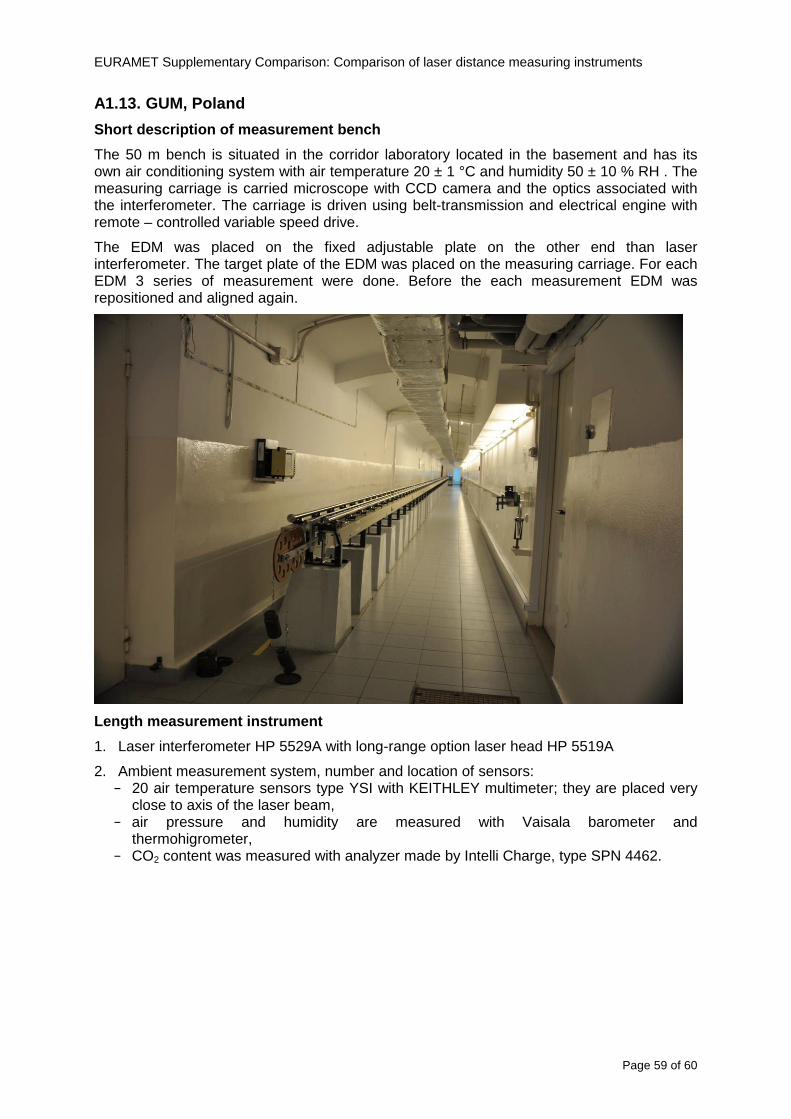
EURAMET Supplementary Comparison Comparison of laser distance measuring instruments
Page 59 of 60
A113 GUM Poland
Short description of measurement bench
The 50 m bench is situated in the corridor laboratory located in the basement and has its own air conditioning system with air temperature 20 plusmn 1 degC and humidity 50 plusmn 10 RH The measuring carriage is carried microscope with CCD camera and the optics associated with the interferometer The carriage is driven using belt-transmission and electrical engine with remote ndash controlled variable speed drive
The EDM was placed on the fixed adjustable plate on the other end than laser interferometer The target plate of the EDM was placed on the measuring carriage For each EDM 3 series of measurement were done Before the each measurement EDM was repositioned and aligned again
Length measurement instrument
1 Laser interferometer HP 5529A with long-range option laser head HP 5519A
2 Ambient measurement system number and location of sensors - 20 air temperature sensors type YSI with KEITHLEY multimeter they are placed very
close to axis of the laser beam - air pressure and humidity are measured with Vaisala barometer and
thermohigrometer - CO2 content was measured with analyzer made by Intelli Charge type SPN 4462
EURAMET Supplementary Comparison Comparison of laser distance measuring instruments
Page 60 of 60
Appendix 2 Corrections of reports
131 CEM Spain
CEM reported two errors in their report
1) Bosch GLM 150 EDM error for 35 m should be -08 mm instead of the indicated 08 mm
2) Leica DISTO D8 EDM error for 35 m should be -019 mm instead of the indicated 019 mm
Proposed corrections have been included in Tables 2 and 4 of the Final Report
132 AS Metrosert Estonia
AS Metrosert reported mixed up of all results for Bosch DLE 50 and Bosch GLM 150 The results and uncertainties sent for DLE 50 was results for GLM 150 and vice versa
Proposed corrections have been included in Tables 1 and 2 of the Final Report
133 INRIM Italy
Among the data reported from INRIM some anomalies were found in the measurements of BOSCH DLE 50 and LEICA DISTO D3a at distances of 20 and 25 m
After preliminary discussion on Draft A it was understood that those anomalies could be explained as a sensitivity of said instruments to the laser light that once diffused by the target is reflected by surfaces parallel to the measurement axis and detected together with the wanted signal The superimposition of the two signals can cause a ldquopullingrdquo effect leading to an overestimation of the distance being the reflected path always longer than the direct one Indeed in the INRIMrsquos set-up the target was mounted pretty close to the flat rail used for the carriage movement being likely responsible for unwanted reflections that disturbed the measurements
Since the errors reported in INRIMrsquos measurements can be ascribed to a defect of BOSCH DLE 50 and LEICA DISTO D3a andor to a lack of description of the working conditions of said instruments INRIM asked to eliminate its measurement points at 20 and 25 m of said instruments from the comparison
Proposed corrections have been included in Tables 1 and 3 of the Final Report
134 JV Norway
Justervesenet has changed the procedure and introduced two apertures instead of only one aperture (iris) which was positioned at half distance between EDM and target The reason is that the reference beam also has an aperture and it is positioned right below the beam from the EDM (130 mm distance between axes) Some diffusively reflected stray light from the EDM target might enter the aperture for the reference beam reflect at the measurement table and reach the detector of the EDM In our calibration set-up we have only seen problems at L gt 30 m We will position the first aperture at ca 5 m from the EDM and then the second aperture at ca 25 m This combination of two apertures will effectively eliminate interference of stray light from the measurement table to the EDM detector for all lengths up to 50 m
Justervesenet also increases the uncertainty component regarding repeatability reproducibility so that the expanded uncertainty increases from 14 mm to 15 mm