Embed Size (px)
Citation preview

More than safety.
Precision MultipleLimit Switches

2
Quality, reliability, precision
Quality, reliability and precision are the
hallmarks of our corporate philosophy.
They represent concepts and values
to which we feel totally committed.
At EUCHNER, quality means that all
our employees take personal respon-
sibility for the company as a whole
and, in particular, for their own field of
work. This individual commitment to
perfection results in products which
are ideally tailored to the customers’
needs and the requirements of the
market. After all: our customers and
their needs are the focus of all our
efforts. Through efficient and effective
use of resources, the promotion of
personal initiative and courage in find-
ing unusual solutions to the benefit of
our customers, we ensure a high level
of customer satisfaction. We familiar-
ize ourselves with their needs, require-
ments and products and we learn
from the experiences of our cus-
tomers’ own customers.
EUCHNER – More than safety.
Quality – made by EUCHNER
More than safety.
Around the world – the Swabian
specialists in motion sequence
control for mechanical and sys-
tems engineering.
EUCHNER’s history began in 1940 with
the establishment of an engineering
office by Emil Euchner. Since that
time, EUCHNER has been involved in
the design and development of switch-
gear for controlling a wide variety of
motion sequences in mechanical and
systems engineering. In 1953, Emil
Euchner founded EUCHNER + Co., a
milestone in the company’s history. In
1952, he developed the first multiple
limit switch – to this day a symbol of
the enterprising spirit of this family-
owned company.
Automation – Safety – ManMachine
Today, our products range from
electromechanical and electronic
components to complex system solu-
tions. With this wide range of products
we can provide the necessary tech-
nologies to offer the right solution for
special requirements – regardless of
whether these relate to reliable and
precise positioning or to components
and systems for safety engineering in
the automation sector.
EUCHNER products are sold through a
world-wide sales network of compe-
tent partners. With our closeness to
the customer and the guarantee of
reliable solutions throughout the
globe, we enjoy the confidence of cus-
tomers all over the world.
Emil Euchner, the
company’s founder and
inventor of the multiple
limit switch, circa 1928.
Automation
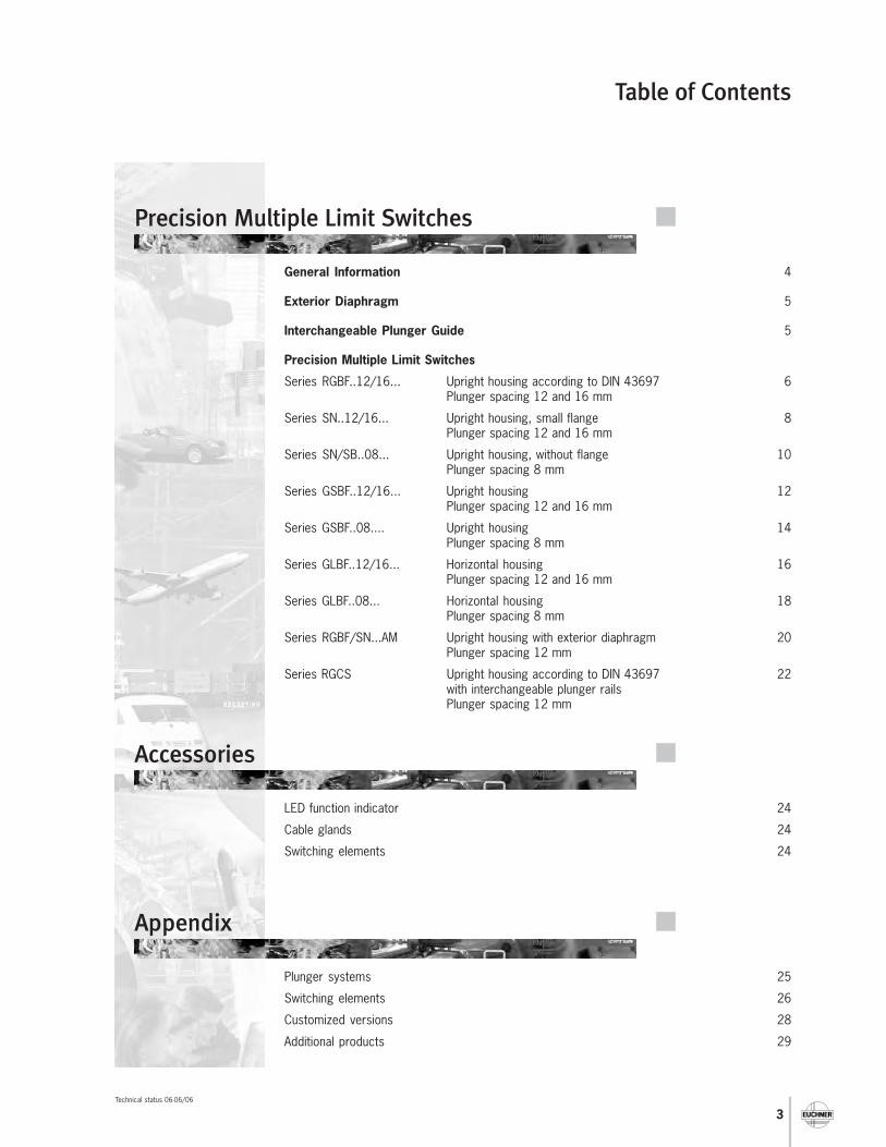
Table of Contents
3
General Information 4
Exterior Diaphragm 5
Interchangeable Plunger Guide 5
Precision Multiple Limit Switches
Series RGBF..12/16... Upright housing according to DIN 43697 6Plunger spacing 12 and 16 mm
Series SN..12/16... Upright housing, small flange 8Plunger spacing 12 and 16 mm
Series SN/SB..08... Upright housing, without flange 10Plunger spacing 8 mm
Series GSBF..12/16... Upright housing 12Plunger spacing 12 and 16 mm
Series GSBF..08.... Upright housing 14Plunger spacing 8 mm
Series GLBF..12/16... Horizontal housing 16Plunger spacing 12 and 16 mm
Series GLBF..08... Horizontal housing 18Plunger spacing 8 mm
Series RGBF/SN...AM Upright housing with exterior diaphragm 20Plunger spacing 12 mm
Series RGCS Upright housing according to DIN 43697 22with interchangeable plunger railsPlunger spacing 12 mm
Precision Multiple Limit Switches
LED function indicator 24
Cable glands 24
Switching elements 24
Accessories
Plunger systems 25
Switching elements 26
Customized versions 28
Additional products 29
Appendix
Technical status 06-06/06
4
Precision Multiple Limit Switches
Subject to technical modifications; no responsibility is accepted for the accuracy of this information.
Application
EUCHNER precision multiple limit switches are used for control-ling and positioning in all areas of mechanical and systems engi-neering and for solving automation tasks.
The main advantages of these highly accurate and reliablepositioning devices are:
� Minimum space requirements due to compact design� Low-cost connection through the use of a common control
cable� Easy access to all switch stations for test and service
purposes� Easy installation
A range of housing versions, including DIN versions, is availableto suit the full spectrum of application fields. A high standard ofquality is guaranteed in every installation position by the degreeof protection IP 67.
Function
Precision multiple limit switches possess several switching ele-ments arranged in a row. The spacing between the individualswitching positions of 12 mm and 16 mm is standardized inaccordance with DIN 43697. The product range is completedwith a particularly compact, space-saving version with a spa-cing of 8 mm.The switching elements are actuated by means of plungers.This is achieved with trip dogs in accordance with DIN 69 639,which are mounted with an interference fit in trip rails accor-ding to DIN 69 638 (see separate catalogue Trip Dogs and TripRails).
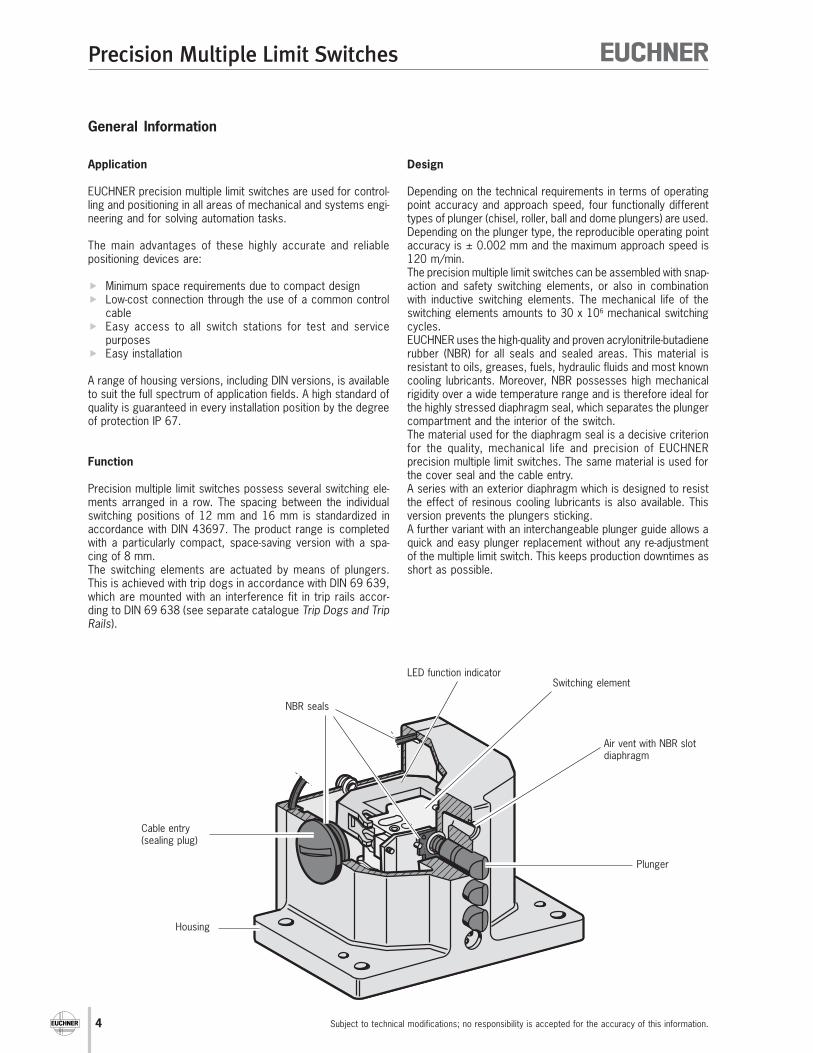
Design
Depending on the technical requirements in terms of operatingpoint accuracy and approach speed, four functionally differenttypes of plunger (chisel, roller, ball and dome plungers) are used.Depending on the plunger type, the reproducible operating pointaccuracy is ± 0.002 mm and the maximum approach speed is120 m/min.The precision multiple limit switches can be assembled with snap-action and safety switching elements, or also in combinationwith inductive switching elements. The mechanical life of theswitching elements amounts to 30 x 106 mechanical switchingcycles.EUCHNER uses the high-quality and proven acrylonitrile-butadienerubber (NBR) for all seals and sealed areas. This material isresistant to oils, greases, fuels, hydraulic fluids and most knowncooling lubricants. Moreover, NBR possesses high mechanicalrigidity over a wide temperature range and is therefore ideal forthe highly stressed diaphragm seal, which separates the plungercompartment and the interior of the switch.The material used for the diaphragm seal is a decisive criterionfor the quality, mechanical life and precision of EUCHNERprecision multiple limit switches. The same material is used forthe cover seal and the cable entry.A series with an exterior diaphragm which is designed to resistthe effect of resinous cooling lubricants is also available. Thisversion prevents the plungers sticking.A further variant with an interchangeable plunger guide allows aquick and easy plunger replacement without any re-adjustmentof the multiple limit switch. This keeps production downtimes asshort as possible.
NBR seals
LED function indicatorSwitching element
Air vent with NBR slotdiaphragm
Housing
Cable entry(sealing plug)
Plunger
General Information
Precision Multiple Limit Switches
5Subject to technical modifications; no responsibility is accepted for the accuracy of this information.
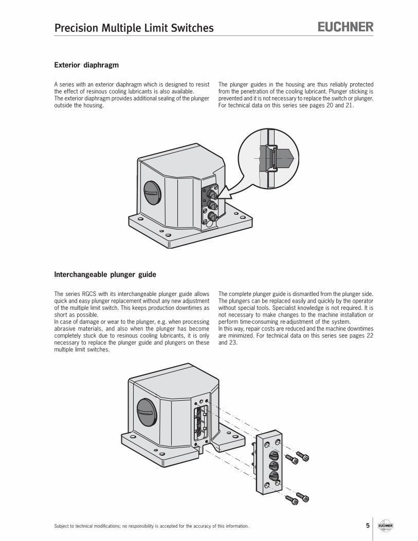
Exterior diaphragm
Interchangeable plunger guide
A series with an exterior diaphragm which is designed to resistthe effect of resinous cooling lubricants is also available.The exterior diaphragm provides additional sealing of the plungeroutside the housing.
The plunger guides in the housing are thus reliably protectedfrom the penetration of the cooling lubricant. Plunger sticking isprevented and it is not necessary to replace the switch or plunger.For technical data on this series see pages 20 and 21.
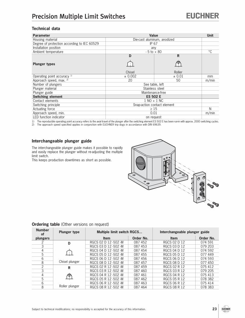
The series RGCS with its interchangeable plunger guide allowsquick and easy plunger replacement without any new adjustmentof the multiple limit switch. This keeps production downtimes asshort as possible.In case of damage or wear to the plunger, e.g. when processingabrasive materials, and also when the plunger has becomecompletely stuck due to resinous cooling lubricants, it is onlynecessary to replace the plunger guide and plungers on thesemultiple limit switches.
The complete plunger guide is dismantled from the plunger side.The plungers can be replaced easily and quickly by the operatorwithout special tools. Specialist knowledge is not required. It isnot necessary to make changes to the machine installation orperform time-consuming re-adjustment of the system.In this way, repair costs are reduced and the machine downtimesare minimized. For technical data on this series see pages 22and 23.
6
Precision Multiple Limit Switches
Subject to technical modifications; no responsibility is accepted for the accuracy of this information.
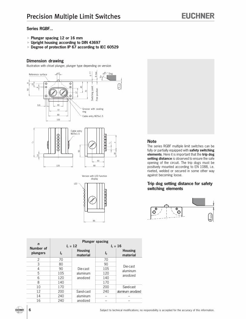
Series RGBF...
� Plunger spacing 12 or 16 mm� Upright housing according to DIN 43697� Degree of protection IP 67 according to IEC 60529
Dimension drawing
40
72
80
6,6
6
228
50
37
45
6±
0,1
8m
ax.
70
30°
max.
5-1
,5100
14
l 2
120
85
50
80
50
l 1
30
n
ø10
LED
NoteThe series RGBF multiple limit switches can befully or partially equipped with safety switchingelements. Here it is important that the trip dogsetting distance is observed to ensure the safeopening of the circuit. The trip dogs must bepositively mounted according to EN 1088, i.e.riveted, welded or secured in some other wayagainst becoming loose.
Trip dog setting distance for safetyswitching elements
Illustration with chisel plunger, plunger type depending on version
Sw
itchin
g p
oin
t
Groove with sealingring
Dog
Free p
osi
tion
Reference surface
Cable entry M25x1.5
Cable entryM25x1.5
Version with LED functiondisplay
Plunger spacingn
l1 = 12 l1 = 16Number of
Housing Housingplungers l2 material
l2 material
2 70 70
3 80 90Die-cast
4 90 Die-cast 105aluminum
5 105 aluminum 120anodized
6 120 anodized 140
8 140 170
10 170 200 Sand-cast
12 200 Sand-cast 240 aluminum anodized
14 240 aluminum – –
16 240 anodized – –

Precision Multiple Limit Switches
7Subject to technical modifications; no responsibility is accepted for the accuracy of this information.
Series
Number of plungers (see table, left)
Plunger types
(D = Chisel, R = Roller (slide bearing), B = Rolle (ball bearing), K = Ball, W = Dome)
Plunger spacing (12 or 16 mm)
Switching elements (ES 502 E, ES 508, ES 514)
LED function indicator (AC/DC 12-60 V = 060, AC 110 V = 110, AC 220 V = 220)
Cable entry with metric thread M25 x 1.5 (M)
Ordering example: Multiple limit switch according to DIN 43697, 8 roller plungers,
plunger spacing 12 mm, switching element ES 502 E, LED 24 V RGBF 08 R 12 -502 LE060-M
Mixed contact assembly: If the multiple limit switch is equipped with safety switching elements and the standard switching element ES 502 E, please note page 28.
R G B F - L E
Technical data
Ordering code - M
Parameter Value UnitHousing material Die-cast aluminum, anodized /
Sand cast aluminum, anodized (see table, left)Degree of protection according to IEC 60529 IP 67Installation position anyAmbient temperature - 5 to + 80 1) °C
D R B K W
Plunger types
Chisel Roller (slide bearing) Roller (ball bearing) Ball 2) Dome
Operating point accuracy 3) ± 0,002 ± 0,01 ± 0,01 ± 0,01 ± 0,002 mmApproach speed, max. 4) 40 80 120 5) 10 10 m/minNumber of plungers See table, leftPlunger material Stainless steelPlunger guide Maintenance-freeSwitching element ES 502 E ES 508 ES 514
Contact elements 1 NO + 1 NC 1 NC 1 NO + 1 NC Switching principle Snap-action Slow-action Snap-action
contact element contact element contact elementActuating force ≥ 20 ≥ 15 ≥ 30 NApproach speed, min. 0.01 - 0.01 m/minDifferential travel 0.8 - 0.6 mmPre-travel to the switching point See travel diagram p. 26 and p. 27Switching frequency ≤ 300 ≤ 50 ≤ 50 min-1
Mech. life (switching cycles) ≥ 30 x 106≥ 1 x 10⁶
Rated impulse withstand voltage Uimp 4 - 4 kVRated insulation voltage Ui 250 VUtilization category AC-12 Ie 10 A Ue 250 V - -according to IEC 60947-5-1 AC-15 Ie 6 A Ue 230 V Ie 6 A Ue 230 V Ie 2.5 A Ue 230 V
DC-13 Ie 6 A Ue 24 V Ie 6 A Ue 24 V Ie 6 A Ue 24 VSwitching current, min. at 10 10 5 mASwitching voltage 12 24 24 DC VConventional thermal current Ith 10 AContact closing time < 4 - ≤ 5 msContact bounce time < 3 - ≤ 3 msShort-circuit protection according to IEC 60269-1
10 A gG(control circuit fuse)Connection type Screw terminalConductor cross-section, max. 2 x 1.5 (per contact) mm2
Approvals for switching elements -LED function indicator (optional) Standard red, for other colours see accessories on request
1) Special versions for low temperature range down to -30 °C on request.2) For safety reasons, multiple limit switches with switching elements ES 508 and ES 514 are not available with ball plungers.3) The reproducible operating point accuracy refers to the axial travel of the plunger after the switching element ES 502 E has been run-in with approx. 2000 switching cycles.4) The approach speed specified applies in conjunction with EUCHNER trip dogs in accordance with DIN 69639.
Special versions for high usage with roller plungers on request.5) Only in conjunction with switching element ES 502 E or ES 508.

8
Precision Multiple Limit Switches
Subject to technical modifications; no responsibility is accepted for the accuracy of this information.
Free p
osi
tion
Series SN...
� Plunger spacing 12 or 16 mm� Upright housing, small flange� Degree of protection IP 67 according to IEC 60529
Dimension drawing
NoteThe series SN multiple limit switches can befully or partially equipped with safety switchingelements. Here it is important that the trip dogsetting distance is observed to ensure the safeopening of the circuit. The trip dogs must bepositively mounted according to EN 1088, i.e.riveted, welded or secured in some other wayagainst becoming loose.
Trip dog setting distance for safetyswitching elements
Illustration with chisel plunger, plunger type depending on version
Sw
itchin
g p
oin
tDogReference surface
CableentryM20x1.5
Version with LED functiondisplay
Plunger spacingn
l1 = 12 l1 = 16 HousingNumber of
materialplungers l2 l3 l4 l2 l3 l4
2 36 19 48
3 48 72 16 24 Die-cast
4 60 1224
84 aluminum
5 72 – – – anodized
6 84 – – –
Version with safetyswitching element ES
514

Precision Multiple Limit Switches
9Subject to technical modifications; no responsibility is accepted for the accuracy of this information.
Series
Number of plungers (see table, left)
Plunger types
(D = Chisel, R = Roller (slide bearing), B = Rolle (ball bearing), K = Ball, W = Dome)
Plunger spacing (12 or 16 mm)
Switching elements (ES 502 E, ES 508, ES 514)
LED function indicator (AC/DC 12-60 V = 060, AC 110 V = 110, AC 220 V = 220)
Cable entry with metric thread M20 x 1.5 (M)
Ordering example: Multiple limit switch, 3 chisel plungers, plunger spacing 12 mm,
switching element ES 508, no LED SN 03 D 12 -508 -M
Mixed contact assembly: If the multiple limit switch is equipped with safety switching elements and the standard switching element ES 502 E, please note page 28.
S N - L E
Technical data
Ordering code
Parameter Value UnitHousing material Die-cast aluminum, anodizedDegree of protection according to IEC 60529 IP 67Installation position anyAmbient temperature - 5 to + 80 1) °C
D R B K W
Plunger types
Chisel Roller (slide bearing) Roller (ball bearing) Ball 2) Dome
Operating point accuracy 3) ± 0,002 ± 0,01 ± 0,01 ± 0,01 ± 0,002 mmApproach speed, max. 4) 40 80 120 5) 10 10 m/minNumber of plungers See table, leftPlunger material Stainless steelPlunger guide Maintenance-freeSwitching element ES 502 E ES 508 ES 514 (on request)
Contact elements 1 NO + 1 NC 1 NC 1 NO + 1 NC Switching principle Snap-action Slow-action Snap-action
contact element contact element contact elementActuating force ≥ 20 ≥ 15 ≥ 30 NApproach speed, min. 0.01 - 0.01 m/minDifferential travel 0.8 - 0.6 mmPre-travel to the switching point See travel diagram p. 26 and p. 27Switching frequency ≤ 300 ≤ 50 ≤ 50 min-1
Mech. life (switching cycles) ≥ 30 x 106≥ 1 x 10⁶
Rated impulse withstand voltage Uimp 4 - 4 kVRated insulation voltage Ui 250 VUtilization category AC-12 Ie 10 A Ue 250 V - -according to IEC 60947-5-1 AC-15 Ie 6 A Ue 230 V Ie 6 A Ue 230 V Ie 2.5 A Ue 230 V
DC-13 Ie 6 A Ue 24 V Ie 6 A Ue 24 V Ie 6 A Ue 24 VSwitching current, min. at 10 10 5 mASwitching voltage 12 24 24 DC VConventional thermal current Ith 10 AContact closing time < 4 - ≤ 5 msContact bounce time < 3 - ≤ 3 msShort-circuit protection according to IEC 60269-1
10 A gG(control circuit fuse)Connection type Screw terminalConductor cross-section, max. 2 x 1.5 (per contact) mm2
Approvals for switching elements -LED function indicator (optional) Standard red, for other colours see accessories on request
1) Special versions for low temperature range down to -30 °C on request.2) For safety reasons, multiple limit switches with switching elements ES 508 and ES 514 are not available with ball plungers.3) The reproducible operating point accuracy refers to the axial travel of the plunger after the switching element ES 502 E has been run-in with approx. 2000 switching cycles.4) The approach speed specified applies in conjunction with EUCHNER trip dogs in accordance with DIN 69639.
Special versions for high usage with roller plungers on request.5) Only in conjunction with switching element ES 502 E or ES 508.
- M
10
Precision Multiple Limit Switches
Subject to technical modifications; no responsibility is accepted for the accuracy of this information.
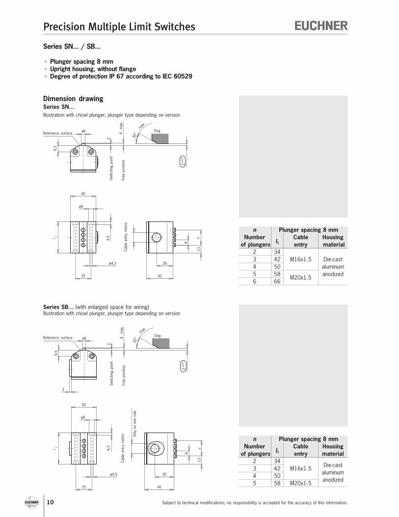
Series SN... / SB...
� Plunger spacing 8 mm� Upright housing, without flange� Degree of protection IP 67 according to IEC 60529
Dimension drawingSeries SN...
Illustration with chisel plunger, plunger type depending on version
Series SB... (with enlarged space for wiring)Illustration with chisel plunger, plunger type depending on version
n Plunger spacing 8 mm
Number Cable Housing
of plungersl1 entry material
2 34
3 42 M16x1.5 Die-cast
4 50 aluminum
5 58M20x1.5
anodized
6 66
n Plunger spacing 8 mm
Number Cable Housing
of plungersl1 entry material
2 34
3 42 M16x1.5Die-cast
4 50aluminum
5 58 M20x1.5anodized
Reference surface
Reference surface
Dog
Sw
itchin
g p
oin
t
Free p
osi
tion
Dog
Sw
itchin
g p
oin
t
Free p
osi
tion
Cable
entr
y m
etr
icC
able
entr
y m
etr
ic Only
on o
ne s
ide

Precision Multiple Limit Switches
11Subject to technical modifications; no responsibility is accepted for the accuracy of this information.
Series (SN, SB see dimension drawing left)
Number of plungers (see table, left)
Plunger types
(D = Chisel, R = Roller, K = Ball)
Plunger spacing (8 mm)
Switching elements (ES 552)
Cable entry with metric thread (M, see table, left)
Ordering example: Multiple limit switch series SB, 3 roller plungers,
plunger spacing 8 mm, switching element ES 552 SB 03 R 08 -552 -M
-
Technical data
Ordering code
Parameter Value UnitHousing material Die-cast aluminum, anodizedDegree of protection according to IEC 60529 IP 67Installation position anyAmbient temperature - 5 to + 80 °C
D R K
Plunger types
Chisel Roller BallOperating point accuracy 1) ± 0.02 ± 0.05 ± 0.03 mmApproach speed, max. 2) 20 50 8 m/minNumber of plungers See table, leftPlunger material Stainless steelPlunger guide Maintenance-freeSwitching element ES 552Contact elements 1 changeover contactSwitching principle Snap-action contact elementActuating force ≥ 15 NApproach speed, min. 0.01 m/minDifferential travel 0.2 mmPre-travel to the switching point See travel diagram p. 26 and p. 27Switching frequency ≤ 200 min-1
Mech. life (switching cycles) ≥ 10 x 106
Rated impulse withstand voltage Uimp 4 kVRated insulation voltage Ui 250 VUtilization category AC-15 Ie 2.5 A Ue 230 Vaccording to IEC 60947-5-1 DC-13 Ie 2 A Ue 24 VSwitching current, min. at 10 mASwitching voltage 24 DC VConventional thermal current Ith 4 AContact closing time ≤ 10 msContact bounce time ≤ 1.5 msShort-circuit protection according to IEC 60269-1
4 A gG(control circuit fuse)Connection type Screw terminalConductor cross-section, max. 1.5 mm2
1) The reproducible operating point accuracy refers to the axial travel of the plunger after the switching element ES 552 has been run-in with approx. 2000 switching cycles.2) The approach speed specified applies in conjunction with EUCHNER trip dogs in accordance with DIN 69639.
- M2550 8
12
Precision Multiple Limit Switches
Subject to technical modifications; no responsibility is accepted for the accuracy of this information.
6 8m
ax.
30°
max.
5-1
,5
l 1
30
n
30
45
26
40
80
82
98
6,6
4
22
828
14
l2
115
45
36
68 (95) *
100
ø10
LED
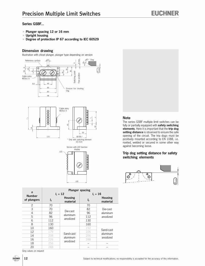
Series GSBF...
� Plunger spacing 12 or 16 mm� Upright housing� Degree of protection IP 67 according to IEC 60529
Dimension drawing
NoteThe series GSBF multiple limit switches can befully or partially equipped with safety switchingelements. Here it is important that the trip dogsetting distance is observed to ensure the safeopening of the circuit. The trip dogs must bepositively mounted according to EN 1088, i.e.riveted, welded or secured in some other wayagainst becoming loose.
Trip dog setting distance for safetyswitching elements
Illustration with chisel plunger, plunger type depending on version
Sw
itchin
g p
oin
t
Groove for sealingring
Dog
Free p
osi
tion
Reference surface
Cable entryM25x1.5
Version with LED functiondisplay
Cable entryM25x1.5
Plunger spacingn
l1 = 12 l1 = 16Number
Housing Housingof plungers l2 material
l2 material
2 70 70
3 70 82 Die-cast
4 82Die-cast
96 aluminum
5 96aluminum
112 anodized
6 112anodized
130
8 130 160
10 160 192Sand-cast
12 179Sand-cast
226aluminum
14 208aluminum
256anodized
16 226anodized
288
18 256 – –
20 288 – –
* Only with switching elementES 514
Grey values on request

Precision Multiple Limit Switches
13Subject to technical modifications; no responsibility is accepted for the accuracy of this information.
Series
Number of plungers (see table, left)
Plunger types
(D = Chisel, R = Roller, K = Ball, W = Dome)
Plunger spacing (12 or 16 mm)
Switching elements (ES 502 E, ES 508, ES 514)
LED function indicator (AC/DC 12-60 V = 060, AC 110 V = 110, AC 220 V = 220)
Cable entry with metric thread M25 x 1.5 (M)
Ordering example: Multiple limit switch, 10 chisel plungers,
plunger spacing 12 mm, switching element ES 508, LED 24 V GSBF 10 D 12 -508 LE060-M
G S B F - L E
Technical data
Ordering code - M
Parameter Value UnitHousing material Die-cast aluminum, anodized /
Sand cast aluminum, anodized (see table, left)Degree of protection according to IEC 60529 IP 67Installation position anyAmbient temperature - 5 to + 80 °C
D R K W
Plunger types
Chisel Roller Ball 1) DomeOperating point accuracy 2) ± 0.002 ± 0.01 ± 0.01 ± 0.002 mmApproach speed, max. 3) 40 80 10 10 m/minNumber of plungers See table, leftPlunger material Stainless steelPlunger guide Maintenance-freeSwitching element ES 502 E ES 508 ES 514
Contact elements 1 NO + 1 NC 1 NC 1 NO + 1 NC Switching principle Snap-action Slow-action Snap-action
contact element contact element contact elementActuating force ≥ 20 ≥ 15 ≥ 30 NApproach speed, min. 0.01 - 0.01 m/minDifferential travel 0.8 - 0.6 mmPre-travel to the switching point See travel diagram p. 26 and p. 27Switching frequency ≤ 300 ≤ 50 ≤ 50 min-1
Mech. life (switching cycles) ≥ 30 x 106≥ 1 x 10⁶
Rated impulse withstand voltage Uimp 4 - 4 kVRated insulation voltage Ui 250 VUtilization category AC-12 Ie 10 A Ue 250 V - -according to IEC 60947-5-1 AC-15 Ie 6 A Ue 230 V Ie 6 A Ue 230 V Ie 2.5 A Ue 230 V
DC-13 Ie 6 A Ue 24 V Ie 6 A Ue 24 V Ie 6 A Ue 24 VSwitching current, min. at 10 10 5 mASwitching voltage 12 24 24 DC VConventional thermal current Ith 10 AContact closing time < 4 - ≤ 5 msContact bounce time < 3 - ≤ 3 msShort-circuit protection according to IEC 60269-1
10 A gG(control circuit fuse)Connection type Screw terminalConductor cross-section, max. 2 x 1.5 (per contact) mm2
Approvals for switching elements -LED function indicator (optional) Standard red, for other colours see accessories -
1) For safety reasons, multiple limit switches with switching elements ES 508 and ES 514 are not available with ball plungers.2) The reproducible operating point accuracy refers to the axial travel of the plunger after the switching element ES 502 E has been run-in with approx. 2000 switching cycles.3) The approach speed specified applies in conjunction with EUCHNER trip dogs in accordance with DIN 69639.

14
Precision Multiple Limit Switches
Subject to technical modifications; no responsibility is accepted for the accuracy of this information.
30°
max
.
12
14
38
45
57
ø6
22
3 4m
ax.
16
l 1
ø5,5
72
ø10
10
28
45
30
8
26
n2
±0,5
Series GSBF...
� Plunger spacing 8 mm� Upright housing� Degree of protection IP 67 according to IEC 60529
Dimension drawingIllustration with chisel plunger, plunger type depending on version
Sw
itchin
g p
oin
t
Dog
Free p
osi
tion
Reference surface
Cable entryM20x1.5
n Plunger spacing 8 mm
Number Housing
of plungersl1 material
2 48
3 64
4 64
5 80
6 80 Sand-
8 96 cast
10 112 aluminum
12 128 anodized
14 144
16 160
18 176
20 192
Cable entryM20x1.5
Grey values on request

Precision Multiple Limit Switches
15Subject to technical modifications; no responsibility is accepted for the accuracy of this information.
Series
Number of plungers (see table, left)
Plunger types
(D = Chisel, R = Roller, K = Ball)
Plunger spacing (8 mm)
Switching elements (ES 552)
Cable entry with metric thread M20 x 1.5 (M)
Ordering example: Multiple limit switch, 8 roller plungers,
plunger spacing 8 mm, switching element ES 552 GSBF 08 R 08 -552 -M
-
Technical data
Ordering code
Parameter Value UnitHousing material Sand-cast aluminum, anodizedDegree of protection according to IEC 60529 IP 67Installation position anyAmbient temperature - 5 to + 80 °C
D R K
Plunger types
Chisel Roller BallOperating point accuracy 1) ± 0.02 ± 0.05 ± 0.03 mmApproach speed, max. 2) 20 50 8 m/minNumber of plungers See table, leftPlunger material Stainless steelPlunger guide Maintenance-freeSwitching element ES 552Contact elements 1 changeover contactSwitching principle Snap-action contact elementActuating force ≥ 15 NApproach speed, min. 0.01 m/minDifferential travel 0.2 mmPre-travel to the switching point See travel diagram p. 26 and p. 27Switching frequency ≤ 200 min-1
Mech. life (switching cycles) ≥ 10 x 106
Rated impulse withstand voltage Uimp 4 kVRated insulation voltage Ui 250 VUtilization category AC-15 Ie 2.5 A Ue 230 Vaccording to IEC 60947-5-1 DC-13 Ie 2 A Ue 24 VSwitching current, min. at 10 mASwitching voltage 24 DC VConventional thermal current Ith 4 AContact closing time ≤ 10 msContact bounce time ≤ 1.5 msShort-circuit protection according to IEC 60269-1
4 A gG(control circuit fuse)Connection type Screw terminalConductor cross-section, max. 1.5 mm2
1) The reproducible operating point accuracy refers to the axial travel of the plunger after the switching element ES 552 has been run-in with approx. 2000 switching cycles.2) The approach speed specified applies in conjunction with EUCHNER trip dogs in accordance with DIN 69639.
- M2550 8G S B F
16
Precision Multiple Limit Switches
Subject to technical modifications; no responsibility is accepted for the accuracy of this information.
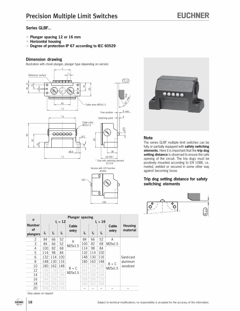
Series GLBF...
� Plunger spacing 12 or 16 mm� Horizontal housing� Degree of protection IP 67 according to IEC 60529
Dimension drawing
NoteThe series GLBF multiple limit switches can befully or partially equipped with safety switchingelements. Here it is important that the trip dogsetting distance is observed to ensure the safeopening of the circuit. The trip dogs must bepositively mounted according to EN 1088, i.e.riveted, welded or secured in some other wayagainst becoming loose.
Trip dog setting distance for safetyswitching elements
Illustration with chisel plunger, plunger type depending on version
Switching point
Dog
Free position
Reference surface
Cable entry M25x1.5
Cable entryM25x1.5
Version with LED functiondisplay
Plunger spacingn
l1 = 12 l1 = 16Number Cable Cable Housing
of entry entry materialplungers l2 l3 l4 l2 l3 l4
2 84 66 52A
84 66 52 A
3 84 66 52M25x1.5
100 82 68 M25x1.5
4 100 82 68 114 98 84
5 114 98 84 132 114 100
6 132 114 100 148 130 116 Sand-cast
8 148 130 116 180 162 148 aluminum
10 180 162 148 212 194 180B + C
anodized
12 199 178 167B + C
244 226 212M25x1.5
14 228 210 196M25x1.5
276 258 244
16 244 226 212 308 290 276
18 276 258 244 340 322 308
20 308 290 276 – – – – –
* Only with switching elementES 514
Grey values on request

Precision Multiple Limit Switches
17Subject to technical modifications; no responsibility is accepted for the accuracy of this information.
Series
Number of plungers (see table, left)
Plunger types
(D = Chisel, R = Roller, K = Ball, W = Dome)
Plunger spacing (12 or 16 mm)
Switching elements (ES 502 E, ES 508, ES 514)
LED function indicator (AC/DC 12-60 V = 060, AC 110 V = 110, AC 220 V = 220)
Cable entry with metric thread M25 x 1.5 (M)
Ordering example: Multiple limit switch, 6 roller plungers,
plunger spacing 16 mm, switching element ES 508, LED 220 V GLBF 06 R 16 -508 LE220-M
G L B F - L E
Technical data
Ordering code
Parameter Value UnitHousing material Sand cast aluminum, anodized (see table, left)Degree of protection according to IEC 60529 IP 67Installation position anyAmbient temperature - 5 to + 80 °C
D R K W
Plunger types
Chisel Roller Ball 1) DomeOperating point accuracy 2) ± 0.002 ± 0.01 ± 0.01 ± 0.002 mmApproach speed, max. 3) 40 80 10 10 m/minNumber of plungers See table, leftPlunger material Stainless steelPlunger guide Maintenance-freeSwitching element ES 502 E ES 508 ES 514
Contact elements 1 NO + 1 NC 1 NC 1 NO + 1 NC Switching principle Snap-action Slow-action Snap-action
contact element contact element contact elementActuating force ≥ 20 ≥ 15 ≥ 30 NApproach speed, min. 0.01 - 0.01 m/minDifferential travel 0.8 - 0.6 mmPre-travel to the switching point See travel diagram p. 26 and p. 27Switching frequency ≤ 300 ≤ 50 ≤ 50 min-1
Mech. life (switching cycles) ≥ 30 x 106≥ 1 x 10⁶
Rated impulse withstand voltage Uimp 4 - 4 kVRated insulation voltage Ui 250 VUtilization category AC-12 Ie 10 A Ue 250 V - -according to IEC 60947-5-1 AC-15 Ie 6 A Ue 230 V Ie 6 A Ue 230 V Ie 2.5 A Ue 230 V
DC-13 Ie 6 A Ue 24 V Ie 6 A Ue 24 V Ie 6 A Ue 24 VSwitching current, min. at 10 10 5 mASwitching voltage 12 24 24 DC VConventional thermal current Ith 10 AContact closing time < 4 - ≤ 5 msContact bounce time < 3 - ≤ 3 msShort-circuit protection according to IEC 60269-1
10 A gG(control circuit fuse)Connection type Screw terminalConductor cross-section, max. 2 x 1.5 (per contact) mm2
Approvals for switching elements -LED function indicator (optional) Standard red, for other colours see accessories -
1) For safety reasons, multiple limit switches with switching elements ES 508 and ES 514 are not available with ball plungers.2) The reproducible operating point accuracy refers to the axial travel of the plunger after the switching element ES 502 E has been run-in with approx. 2000 switching cycles.3) The approach speed specified applies in conjunction with EUCHNER trip dogs in accordance with DIN 69639.
- M

18
Precision Multiple Limit Switches
Subject to technical modifications; no responsibility is accepted for the accuracy of this information.
Series GLBF...
� Plunger spacing 8 mm� Horizontal housing� Degree of protection IP 67 according to IEC 60529
Dimension drawingIllustration with chisel plunger, plunger type depending on version
Switching pointD
og
Free position
Reference surface
Cable entryM20x1.5
Cable entryM20x1.5
n Plunger spacing 8 mm
NumberHousing
of plungers l1 l2 l3 material
2 64 50 39
3 80 66 55
4 80 66 55Sand-cast
5 96 82 71aluminum
6 96 82 71anodized
8 112 98 87
10 128 114 103
12 144 130 119
Grey values on request

Precision Multiple Limit Switches
19Subject to technical modifications; no responsibility is accepted for the accuracy of this information.
Series
Number of plungers (see table, left)
Plunger types
(D = Chisel, R = Roller, K = Ball)
Plunger spacing (8 mm)
Switching elements (ES 552)
Cable entry with metric thread M20 x 1.5 (M)
Ordering example: Multiple limit switch, 12 ball plungers,
plunger spacing 8 mm, switching element ES 552 GLBF 12 K 08 -552 -M
-
Technical data
Ordering code
Parameter Value UnitHousing material Sand-cast aluminum, anodizedDegree of protection according to IEC 60529 IP 67Installation position anyAmbient temperature - 5 to + 80 °C
D R K
Plunger types
Chisel Roller BallOperating point accuracy 1) ± 0.02 ± 0.05 ± 0.03 mmApproach speed, max. 2) 20 50 8 m/minNumber of plungers See table, leftPlunger material Stainless steelPlunger guide Maintenance-freeSwitching element ES 552Contact elements 1 changeover contactSwitching principle Snap-action contact elementActuating force ≥ 15 NApproach speed, min. 0.01 m/minDifferential travel 0.2 mmPre-travel to the switching point See travel diagram p. 26 and p. 27Switching frequency ≤ 200 min-1
Mech. life (switching cycles) ≥ 10 x 106
Rated impulse withstand voltage Uimp 4 kVRated insulation voltage Ui 250 VUtilization category AC-15 Ie 2.5 A Ue 230 Vaccording to IEC 60947-5-1 DC-13 Ie 2 A Ue 24 VSwitching current, min. at 10 mASwitching voltage 24 DC VConventional thermal current Ith 4 AContact closing time ≤ 10 msContact bounce time ≤ 1.5 msShort-circuit protection according to IEC 60269-1
4 A gG(control circuit fuse)Connection type Screw terminalConductor cross-section, max. 1.5 mm2
1) The reproducible operating point accuracy refers to the axial travel of the plunger after the switching element ES 552 has been run-in with approx. 2000 switching cycles.2) The approach speed specified applies in conjunction with EUCHNER trip dogs in accordance with DIN 69639.
- M2550 8G L B F

20
Precision Multiple Limit Switches
Subject to technical modifications; no responsibility is accepted for the accuracy of this information.
Series RGBF...AM / SN...AM with exterior diaphragm
� Plunger spacing 12 mm� Upright housing� Degree of protection IP 67 according to IEC 60529
Sw
itchin
g p
oin
t
Dog
Free p
osi
tion
Reference surface
Cable entry M25x1.5
n Plunger spacing 12 mm
Number Housing
of plungersl1 material
2 70
3 80
4 90Die-cast
5 105aluminum
6 120anodized
8 140
Cable entryM25x1.5
Dimension drawingSeries RGBF... (according to DIN 43697)
Illustration with chisel plunger, plunger type depending on version
Series SN...Illustration with chisel plunger, plunger type depending on version
n Plunger spacing 12 mm
Number Housing
of plungersl1 l2 material
2 36 19
3 48 Die-cast
4 6024
aluminum
5 72 anodized
6 84
Groove with sealing ring
Sw
itchin
g p
oin
t
Dog
Free p
osi
tion
Reference surface
Cable entryM20x1.5
Figure: RGBF...AM design

Precision Multiple Limit Switches
21Subject to technical modifications; no responsibility is accepted for the accuracy of this information.
Technical data
Parameter Value UnitHousing material Die-cast aluminum, anodizedDegree of protection according to IEC 60529 IP 67Installation position anyAmbient temperature - 5 to + 80 °C
D R
Plunger types
Chisel RollerOperating point accuracy 1) ± 0.002 ± 0.01 mmApproach speed, max. 2) 20 50 m/minNumber of plungers See table, leftPlunger material Stainless steelPlunger guide Maintenance-freeSwitching element ES 502 EContact elements 1 NO + 1 NCSwitching principle Snap-action contact elementActuating force ≥ 15 NApproach speed, min. 0.01 m/minLED function indicator on request
1) The reproducible operating point accuracy refers to the axial travel of the plunger after the switching element ES 502 E has been run-in with approx. 2000 switching cycles.2) The approach speed specified applies in conjunction with EUCHNER trip dogs in accordance with DIN 69639.
Exterior diaphragm
The exterior diaphragm provides additional protection to the plungerguide.Plunger sticking, primarily caused by resinous lubricatingcoolants, can be prevented by this exterior diaphragm version.
Ordering table (Other versions on request)
Number of
Plunger type Multiple limit switch exterior diaphragm version
plungers Series RGBF... Order No. Series SN... Order No.2 D RGBF 02 D 12 -502 AM -M 082 325 SN 02 D 12 -502 AM -M 086 5843 RGBF 03 D 12 -502 AM -M 088 365 SN 03 D 12 -502 AM -M 086 5854 RGBF 04 D 12 -502 AM -M 082 326 SN 04 D 12 -502 AM -M 086 5865 RGBF 05 D 12 -502 AM -M 088 366 SN 05 D 12 -502 AM -M 088 7526 RGBF 06 D 12 -502 AM -M 087 097 SN 06 D 12 -502 AM -M 088 7538 Chisel plunger RGBF 08 D 12 -502 AM -M 087 135 – –2 R RGBF 02 R 12 -502 AM -M 087 098 SN 02 R 12 -502 AM -M 079 2893 RGBF 03 R 12 -502 AM -M 088 364 SN 03 R 12 -502 AM -M 086 5874 RGBF 04 R 12 -502 AM -M 082 327 SN 04 R 12 -502 AM -M 086 5885 RGBF 05 R 12 -502 AM -M 087 099 SN 05 R 12 -502 AM -M 088 7656 RGBF 06 R 12 -502 AM -M 087 100 SN 06 R 12 -502 AM -M 088 7668 Roller plunger RGBF 08 R 12 -502 AM -M 085 730 – –

22
Precision Multiple Limit Switches
Subject to technical modifications; no responsibility is accepted for the accuracy of this information.
Series RGCS... with interchangeable plunger guide
� Plunger spacing 12 mm� Upright housing according to DIN 43697� Degree of protection IP 67 according to IEC 60529
Sw
itchin
g p
oin
t
Dog
Free p
osi
tion
Reference surface
Cable entry M25x1.5
Cable entryM25x1.5
Dimension drawingIllustration with chisel plunger, plunger type depending on version
Groove with sealing ring
Features� Plunger guide made of special material� Can be dismantled from the plunger side� Complete plunger guide can be replaced
n Plunger spacing 12 mm
Number Housing
of plungersl1 material
2 70
3 80
4 90Die-cast
5 105aluminum
6 120anodized
8 140
Precision Multiple Limit Switches
23Subject to technical modifications; no responsibility is accepted for the accuracy of this information.
Technical data
Parameter Value UnitHousing material Die-cast aluminum, anodizedDegree of protection according to IEC 60529 IP 67Installation position anyAmbient temperature - 5 to + 80 °C
D R
Plunger types
Chisel RollerOperating point accuracy 1) ± 0.002 ± 0.01 mmApproach speed, max. 2) 20 50 m/minNumber of plungers See table, leftPlunger material Stainless steelPlunger guide Maintenance-freeSwitching element ES 502 EContact elements 1 NO + 1 NCSwitching principle Snap-action contact elementActuating force ≥ 15 NApproach speed, min. 0.01 m/minLED function indicator on request
1) The reproducible operating point accuracy refers to the axial travel of the plunger after the switching element ES 502 E has been run-in with approx. 2000 switching cycles.2) The approach speed specified applies in conjunction with EUCHNER trip dogs in accordance with DIN 69639.
Interchangeable plunger guide
The interchangeable plunger guide makes it possible to rapidlyand easily replace the plunger without re-adjusting the multiplelimit switch.This keeps production downtimes as short as possible.
Ordering table (Other versions on request)
Numberof
Plunger type Multiple limit switch RGCS... Interchangeable plunger guide
plungers Item Order No. Item Order No.2 D RGCS 02 D 12 -502 -M 087 452 RGCS 02 D 12 074 5913 RGCS 03 D 12 -502 -M 087 453 RGCS 03 D 12 079 2034 RGCS 04 D 12 -502 -M 087 454 RGCS 04 D 12 074 5925 RGCS 05 D 12 -502 -M 087 455 RGCS 05 D 12 077 4496 RGCS 06 D 12 -502 -M 087 456 RGCS 06 D 12 074 5938 Chisel plunger RGCS 08 D 12 -502 -M 087 457 RGCS 08 D 12 077 4502 R RGCS 02 R 12 -502 -M 087 459 RGCS 02 R 12 075 4123 RGCS 03 R 12 -502 -M 087 460 RGCS 03 R 12 079 2054 RGCS 04 R 12 -502 -M 087 461 RGCS 04 R 12 075 4135 RGCS 05 R 12 -502 -M 087 462 RGCS 05 R 12 078 3826 RGCS 06 R 12 -502 -M 087 463 RGCS 06 R 12 075 4148 Roller plunger RGCS 08 R 12 -502 -M 087 464 RGCS 08 R 12 078 383
24
Precision Multiple Limit Switches
Subject to technical modifications; no responsibility is accepted for the accuracy of this information.
Accessories
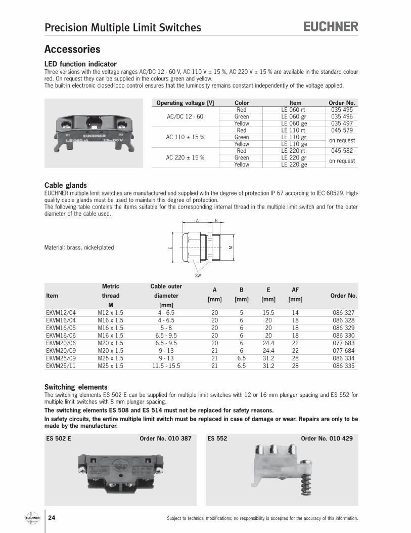
LED function indicatorThree versions with the voltage ranges AC/DC 12 - 60 V, AC 110 V ± 15 %, AC 220 V ± 15 % are available in the standard colourred. On request they can be supplied in the colours green and yellow.The built-in electronic closed-loop control ensures that the luminosity remains constant independently of the voltage applied.
Operating voltage [V] Color Item Order No.Red LE 060 rt 035 495
AC/DC 12 - 60 Green LE 060 gr 035 496Yellow LE 060 ge 035 497Red LE 110 rt 045 579
AC 110 ± 15 % Green LE 110 grYellow LE 110 ge
on request
Red LE 220 rt 045 582AC 220 ± 15 % Green LE 220 gr
Yellow LE 220 geon request
Metric Cable outerA B E AF
Item thread diameter[mm] [mm] [mm] [mm]
Order No.
M [mm]
EKVM12/04 M12 x 1.5 4 - 6.5 20 5 15.5 14 086 327
EKVM16/04 M16 x 1.5 4 - 6.5 20 6 20 18 086 328
EKVM16/05 M16 x 1.5 5 - 8 20 6 20 18 086 329
EKVM16/06 M16 x 1.5 6.5 - 9.5 20 6 20 18 086 330
EKVM20/06 M20 x 1.5 6.5 - 9.5 20 6 24.4 22 077 683
EKVM20/09 M20 x 1.5 9 - 13 21 6 24.4 22 077 684
EKVM25/09 M25 x 1.5 9 - 13 21 6.5 31.2 28 086 334
EKVM25/11 M25 x 1.5 11.5 - 15.5 21 6.5 31.2 28 086 335
E M
BA
SW
Cable glandsEUCHNER multiple limit switches are manufactured and supplied with the degree of protection IP 67 according to IEC 60529. High-quality cable glands must be used to maintain this degree of protection.The following table contains the items suitable for the corresponding internal thread in the multiple limit switch and for the outerdiameter of the cable used.
Material: brass, nickel-plated
Switching elementsThe switching elements ES 502 E can be supplied for multiple limit switches with 12 or 16 mm plunger spacing and ES 552 formultiple limit switches with 8 mm plunger spacing.
The switching elements ES 508 and ES 514 must not be replaced for safety reasons.
In safety circuits, the entire multiple limit switch must be replaced in case of damage or wear. Repairs are only to bemade by the manufacturer.
ES 502 E Order No. 010 387 ES 552 Order No. 010 429

Precision Multiple Limit Switches
25Subject to technical modifications; no responsibility is accepted for the accuracy of this information.
Plunger types
Depending on the technical requirements, four functionally diffe-rent types of plunger (chisel, roller, ball and domed plungers)are used for 8, 12 or 16 mm plunger spacing respectively.
Chisel plunger DHardened and polish-ground.Operating point accuracy up to ± 0.002 mm.Max. approach speed of 40 m/min.
Roller plunger R with slide bearing(standard version for roller plunger)Hardened roller.Operating point accuracy up to ± 0.01 mm.Max. approach speed of 80 m/min.
Roller plunger R with ball bearingHardened roller.Operating point accuracy up to ± 0.01 mm.Max. approach speed of 120 m/min.
2 s
sFree position Operating point End position Reset point
Pre
trave
l
Referencesurface
Ove
rtra
ve
l
Move
me
nt
diffe
ren
tia
l
Re
se
ttr
ave
l
Idle
tra
ve
l
To
tal
trave
l
General
Plungers for precision multiple limit switches are made of stain-less steel and are extremely accurate.In conjunction with a specially surface-treated plunger guide, theextremely reliable and maintenance-free operation extends evenbeyond the guaranteed mechanical life.
There are two different types of actuating system, depending onapplication. For standard applications, the plunger is fitted witha telescopic device.
Ball plunger K(not in conjunction with safety switching elements)Hardened ball.Can be actuated from various directions.Operating point accuracy up to ± 0.01 mm.Max. approach speed of 10 m/min.
Dome plunger W(instead of ball plungers in safety switching elements)Hardened and polish-ground.Can be actuated from various directions.Operating pointaccuracy up to ± 0.002 mm.Max. approach speed of 10 m/min.
Plunger systems
With this system the plunger can be depressed to the referencesurface without damaging the switching element.Precision multiple limit switches with safety switching elementshave a „rigid“ plunger instead of a plunger with telescopic action;the rigid plunger provides a positively driven NC contact inaccordance with EN 60947. This means that the contact pointwill be reliably opened in the event of mechanical failure of theswitching element - e.g. owing to the failure of a contact springor contact weld resulting from an overload.
Plunger travel
The graphic shows the various positions of the plunger whenactuated by a trip dog.The precise values for the relevant design are shown in thetechnical data.
Travel ratio for plunger/trip dog
All the plunger travel data shown in the technical data refers toaxial actuation. When using our trip dogs in accordance withDIN 69639, this travel is doubled at the trip rail.
Appendix

26
Precision Multiple Limit Switches
Subject to technical modifications; no responsibility is accepted for the accuracy of this information.
Switching elements
General Information
Different switching elements are available for various applications. Along with the standard switching elements with snap-action function,switching elements with positively driven NC contacts can be used for safety functions.
1) A snap-action contact element has a contact element which opens or closes regardless of its actuation speed.
13-1
421-2
213-1
421-2
2
0
1
2
3
4
6
7
5
6
8m
ax.
5-1
,5
7,5
Snap-action contact element 1) according to DIN 43695 with one NO and one NC contact.Double gap, electrically isolated contact elements, silver contact, electro-gold plated.Screw terminal with self-lifting clamp washers.Used in multiple limit switches with 12 and 16 mm plunger spacing.
Switching element ES 502 E
Approval
13
14
21
22
ES 502 E
Pin assignment and switching function Travel diagram forseries RGBF.../GSBF.../GLBF...with plunger spacing 12 and 16 mm
Free positionSwitching point
max. stroke
Travel diagram forseries SN...with plunger spacing 12 and 16 mm
13
-14
21
-22
13
-14
21
-22
0
1
2
3
4
6
5
5
6,5
max.
1,5
4-1
,5
Free positionSwitching point
max. stroke
Contacts openContacts closed
1-2
1-4
0
1
2
3
3,5
3
4m
ax.
2±
0,5
Snap-action contact element 1) with one changeover contact.Silver contact, electro-gold plated. Screw terminal.Used in multiple limit switches with 8 mm plunger spacing.
Switching element ES 552
Pin assignment and switching function Travel diagram forseries GSBF.../GLBF.../SN.../SB...with plunger spacing 8 mm
Free positionSwitching point
max. stroke
Contacts openContacts closed
1
2
4
ES 552

Precision Multiple Limit Switches
27Subject to technical modifications; no responsibility is accepted for the accuracy of this information.
6
8m
ax.
13
-14
21
-22
13
-14
21
-22
0
1
2
3
4
5
4-0
,5
1) A snap-action contact element has a contact element which opens or closes regardless of its actuation speed.
2) A slow-action contact element has a contact element which opens and closes depending on its actuation speed.
EUCHNER switching elements marked with this symbol meet the IEC 60947-5-1 requirements for multiple limit switcheswith positively driven NC contacts.Safety switching elements marked with this symbol are not available as replacement switching elements.
Electrical lifeThe electrical life of the switching elements is dependent on the electrical load, the switching frequency and the approach speed.
Magnetic snap-action contact element 1) with one positively driven NC contact and oneNO contact.Double gap, electrically isolated contact elements, silver contact, electro-gold plated.Screw terminal with self-lifting clamp washers.Used in multiple limit switches with 12 and 16 mm plunger spacing.
Switching element ES 514(safety switching element)
13
14
21
22
ES 514
Pin assignment and switching function Travel diagram forseries RGBF.../GSBF.../GLBF...with plunger spacing 12 and 16 mm
Free positionSwitching point
max. stroke
Travel diagram forseries SN...with plunger spacing 12 and 16 mm
Free positionSwitching point
max. stroke
Contacts positively drivenContacts openContacts closed
6
8m
ax.
21-2
2
0
2
3
4
55,5
1
4-0
,5
Slow-action contact element 2) with one positively driven NC contact.Double gap, silver contact, electro-gold plated.Screw terminal with self-lifting clamp washers.Used in multiple limit switches with 12 and 16 mm plunger spacing.
Switching element ES 508(safety switching element)
21
22
ES 508
Pin assignment and switching function Travel diagram forseries RGBF.../GSBF.../GLBF...with plunger spacing 12 and 16 mm
Free positionSwitching point
max. stroke
Travel diagram forseries SN...with plunger spacing 12 and 16 mm
5
6,5
max.
21
-22
0
2
3
4
5
1
3,5
1,5
3-0
,5
Free positionSwitching point
max. stroke
Contacts positively drivenContacts openContacts closed
5
6,5
max.
13
-14
21
-22
13
-14
21
-22
0
1
2
3
4
4,5
1,5
3,5
3-0
,5

28
Precision Multiple Limit Switches
Subject to technical modifications; no responsibility is accepted for the accuracy of this information.
Approach speed and performance with roller plungers
Using high quality ball bearings and technology matched to the application, approach speeds up to 120 m/min and very highperformance can be realized at the same time.
Low temperature
The selection of specially tested materials permits operation at ambient temperatures down to -30 °C.
Interchangeable plunger guideExterior diaphragm
Resinous lubricating coolants and the processing of abrasive materials can result in failure of the plunger function in particularlydifficult conditions. Proven series, shown on pages 20 to 23, minimizes downtimes and reduces repair costs.
Mixed contact assembly (only in multiple limit switches with 12 and 16 mm plunger spacing)
For specific functions on machines and systems, e.g. end of travel limit switching, EMERGENCY STOP or similar, it is necessary thatone or more stations on multiple limit switches are equipped with safety switching elements. See the ordering example below forinformation on the specification of such multiple limit switches.
The following requirements are to be observed:
� On upright multiple limit switches (e.g. RGBF...) it is necessary to start with the safety station/s on the flange side.
� On horizontal multiple limit switches (e.g. RGBF...) it is necessary to start with the safety station/s on the left side (view on theplunger side).
� If several safety stations are to be fitted, these must be fitted directly one after the other.
� The remaining stations are equipped with standard switching elements ES 502 E.
Customized versions
R G B F -0 8 R 1 2 3 5 0 8
Number of safety stations
Safety switching element ES 508
Ordering example: Multiple limit switch series RGBF, 8 roller plunger, plunger spacing 12 mm,
stations 1 to 3 with safety switching elements ES 508,
remaining stations with standard switching elements ES 502 E
If a multiple limit switch of mixed assembly cannot be specified with this ordering code, we would ask you to state your order in plainEnglish.
Multiple limit switches with 12 mm plunger spacing can be assembled on request with a mixture of mechanical and inductiveswitching elements.
- M

Precision Multiple Limit Switches
29Subject to technical modifications; no responsibility is accepted for the accuracy of this information.
Inductive multiple limit switches with long me-chanical life
EUCHNER offers inductive multiple limit switches as an alter-native to precision multiple limit switches. There are five diffe-rent designs available for various areas of application with 8, 12or 16 mm proximity switch spacing respectively. The dimensionsof these versions are such that they can be interchanged withprecision multiple limit switches.
The crucial advantages
� Very long mechanical life� High switching frequency� Contact-less, non-reactive switching� Safe switching under extreme conditions� Resistant to strong vibrations, heavy dirt and aggressive
fluids
Trip rails / trip dogs
U-trip railsenable the adjustment of the trip dogs from the switch side. Thetrip dogs can be installed and adjusted quickly and easily in anylocation.
U-trip dogsare designed for use in U-trip rails. They have an expansion plateclamp and enable precise adjustment, even when the limit switchis activated.
G-trip railsenable the adjustment of trip dogs from the side opposite theswitch. They are made of steel and are protected from corrosionby a special surface treatment. Trip rails can be ordered pre-assembled or as a component for self-assembly.
G-trip dogsare designed for use in G-trip rails. The trip dogs are clamped inthe trip rail by a hexagon socket screw with spring washer. Thiswasher locks the trip dog in place even when the trip rail is in avertical position and allows precise adjustment.
Additional Products