Embed Size (px)
Citation preview

More than safety.

2
Quality, reliability, precision
Quality, reliability and precision are the
hallmarks of our corporate philosophy.
They represent concepts and values
to which we feel totally committed.
At EUCHNER, quality means that all
our employees take personal respon-
sibility for the company as a whole
and, in particular, for their own field of
work. This individual commitment to
perfection results in products which
are ideally tailored to the customers’
needs and the requirements of the
market. After all: our customers and
their needs are the focus of all our
efforts. Through efficient and effective
use of resources, the promotion of
personal initiative and courage in find-
ing unusual solutions to the benefit of
our customers, we ensure a high level
of customer satisfaction. We familiar-
ize ourselves with their needs, require-
ments and products and we learn
from the experiences of our cus-
tomers’ own customers.
EUCHNER – More than safety.
Quality – made by EUCHNER
More than safety.Around the world – the Swabian
specialists in motion sequence
control for mechanical and sys-
tems engineering.
EUCHNER’s history began in 1940 with
the establishment of an engineering
office by Emil Euchner. Since that
time, EUCHNER has been involved in
the design and development of switch-
gear for controlling a wide variety of
motion sequences in mechanical and
systems engineering. In 1953, Emil
Euchner founded EUCHNER + Co., a
milestone in the company’s history. In
1952, he developed the first multiple
limit switch – to this day a symbol of
the enterprising spirit of this family-
owned company.
Automation – Safety – ManMachine
Today, our products range from
electromechanical and electronic
components to complex system solu-
tions. With this wide range of products
we can provide the necessary tech-
nologies to offer the right solution for
special requirements – regardless of
whether these relate to reliable and
precise positioning or to components
and systems for safety engineering in
the automation sector.
EUCHNER products are sold through a
world-wide sales network of compe-
tent partners. With our closeness to
the customer and the guarantee of
reliable solutions throughout the
globe, we enjoy the confidence of cus-
tomers all over the world.
Emil Euchner, the
company’s founder and
inventor of the multiple
limit switch, circa 1928.
ManMachine

3
Contents
Technical Status 02-12/06
Hand-Held Pendant Stations/Handwheels
General
About this catalog 4
How can I find the right product? 4
Standards and approvals 5
Hand-Held Pendant Stations 6
Function and technology used in hand-held pendant stations 6
Hand-held pendant stations HBA 10
Hand-held pendant stations HBE 18
Hand-held pendant stations HBL 26
Kit for Hand-Held Pendant Stations
Kit for hand-held pendant stations HBA 31
Kit for hand-held pendant stations HBE 37
Kit for hand-held pendant stations HBL 41
Accessories for Kit for Hand-Held Pendant Stations 45
Accessories for kit for hand-held pendant stations, all designs 46
Accessories for kit for hand-held pendant stations HBA 53
Accessories for kit for hand-held pendant stations HBE/HBL 54
Holder for Hand-Held Pendant Stations 56
Electronic Handwheels 57
Function and technology used in handwheels 58
Handwheel HKD 60
Handwheel HKC 62
Handwheel HKA 64
Handwheel HWA 66
Handwheel HWB 68
Handwheel HWD 70
Handwheel HWE 71
Handwheel HWF 72
Accessories for Handwheels 73
Appendix
Dimension drawing housing top shell HBA 74
Assembly drawings housing HBE/HBL 75
Request form for hand-held pendant stations HBA without handwheels 76
Request form for hand-held pendant stations HBA with handwheels 77
Request form for hand-held pendant stations HBE 78
Request form for hand-held pendant stations HBL 79
Item Index
Index by item designation 80
Index by order numbers 82
Overview of Range 85
4
General
Subject to technical modifications; no responsibility is accepted for the accuracy of this information. Devices supplied may vary slightly from the illustration in the catalog.
10
Hand-Held Pendant Stations
Subject to technical modifications; no responsibility is accepted for the accuracy of this information. Devices supplied may vary slightly from the illustration in the catalog.
Hand-held pendant stations HBA
Dimension drawing Handwheel 100 pulses, wear-freemagnetic detent
2 enabling switches, 2-stage, 1 NOcontact each
Depending on version: Tamper-proof EMERGENCY STOP
device according to EN 418,dual-channel
2 selector switches, 5 positions each(X, Y, Z, 4, 5 and 0, 1, 10, 100, 1000)
3 membrane pushbuttons, 1 NOcontact each
Notes
For holder HBA for hand-held pendant stations,
see Accessories page 56
For related 23-pin flange socket, see
Accessories page 50
Technical data
Parameter Value Unit
Housing HBA
Material Plastic
Color Gray RAL 7040
Operating temperature 0 ... +50 °C
Storage temperature -20 ... +50 °C
Degree of protection according to EN 60529 / NEMA IP 65 / 250-12
Connection Coiled cable, expandable to 3.5 m, 23-pin plug connector
Weight Approx. 1.3 kg
Handwheel
Pulses / revolution 100
Power supply 5 ± 5% V DC
Output specifications RS422A
Enabling switch, 2-stage
Switching elements 2, 1 NO contact each
Connection ratings 30 V AC / 0.4 A; 30 V DC / 0.1 A
EMERGENCY STOP device
Standard EN 418
Switching elements 1, 2 NC contacts
Utilization category to IEC 60947-5-1 DC-13, Ue 24 V, Ie 3 A
Selector switch
Output code See wiring diagram
Switching voltage max. 30 V DC
Switching current max. 200 mA
Breaking capacity max. 1 W
Membrane keypad
Switching elements 3, 1 NO contact each
Switching voltage max. 30 V DC
Switching current max. 100 mA
Breaking capacity max. 1 W
160
∅ 85
S2 S3
S1
S4
S5
S6
S8
S7
67
A1
Mountingmagnet
Cable length stretched3500 mm
Plug connector23-pin
9
Hand-Held Pendant Stations
Subject to technical modifications; no responsibility is accepted for the accuracy of this information. Devices supplied may vary slightly from the illustration in the catalog.
Overview of hand-held pendant stations
Features
Version
Hand-held pendant stations
HBA
10ff
Hand-held pendant stations
HBE
18ff
Hand-held pendant stations
HBL
26ff
Selector
switch
Key-
operated
switch
Push-
button
Enabling
switchEMERGENCY
STOP device
Membrane
keypad
LCD
display
RS422
interface,
3964R
protocol
PageHand-
wheel2-st. 3-st.
3
Contents
Technical Status 01-11/06
Hand-Held Pendant Stations/Handwheels
General
About this catalog 4
How can I find the right product? 4
Standards and approvals 5
Hand-Held Pendant Stations 6
Function and technology used in hand-held pendant stations 6
Hand-held pendant stations HBA 10
Hand-held pendant stations HBE 18
Hand-held pendant stations HBL 26
Kit for Hand-Held Pendant Stations
Kit for hand-held pendant stations HBA 31
Kit for hand-held pendant stations HBE 37
Kit for hand-held pendant stations HBL 41
Accessories for Kit for Hand-Held Pendant Stations 45
Accessories for kit for hand-held pendant stations, all designs 46
Accessories for kit for hand-held pendant stations HBA 53
Accessories for kit for hand-held pendant stations HBE/HBL 54
Holder for Hand-Held Pendant Stations 56
Electronic Handwheels 57
Function and technology used in handwheels 58
Handwheel HKD 60
Handwheel HKC 62
Handwheel HKA 64
Handwheel HWA 66
Handwheel HWB 68
Handwheel HWD 70
Handwheel HWE 71
Handwheel HWF 72
Accessories for Handwheels 73
Appendix
Dimension drawing housing top shell HBA 74
Assembly drawings housing HBE/HBL 75
Request form for hand-held pendant stations HBA without handwheels 76
Request form for hand-held pendant stations HBA with handwheels 77
Request form for hand-held pendant stations HBE 78
Request form for hand-held pendant stations HBL 79
Item Index
Index by item designation 80
Index by order numbers 82
Overview of Range 85
Select the required information in the table of contents
General overview
No
Yes
Detailed overview Detailed overview
Find Product
Find the required productin the item index and
select in the ordering table
Select the required product in the
ordering table
Refine selectionby selecting the
required product featuresin the selection table
Do you know the order number
or the item designation?
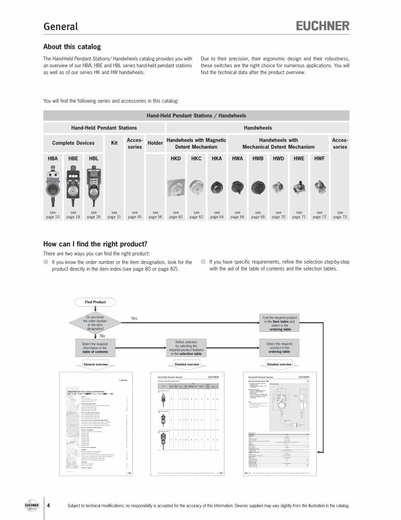
About this catalog
The Hand-held Pendant Stations/ Handwheels catalog provides you with
an overview of our HBA, HBE and HBL series hand-held pendant stations
as well as of our series HK and HW handwheels.
How can I find the right product?
There are two ways you can find the right product:
u If you know the order number or the item designation, look for the
product directly in the item index (see page 80 or page 82).
Hand-Held Pendant Stations / Handwheels
Complete Devices KitAcces-
soriesHolder
Hand-Held Pendant Stations Handwheels
seepage 10
HBA
Acces-
sories
seepage 18
HBE
seepage 26
HBL
seepage 31
seepage 45
seepage 56
seepage 60
HKD
seepage 62
HKC
seepage 64
HKA
seepage 66
HWA
seepage 68
HWB
seepage 70
HWD
seepage 71
HWE
seepage 72
HWF
seepage 73
Handwheels with Magnetic
Detent Mechanism
Handwheels with
Mechanical Detent Mechanism
You will find the following series and accessories in this catalog:
Due to their precision, their ergonomic design and their robustness,
these switches are the right choice for numerous applications. You will
find the technical data after the product overview.
v If you have specific requirements, refine the selection step-by-step
with the aid of the table of contents and the selection tables.

5
General
Subject to technical modifications; no responsibility is accepted for the accuracy of this information. Devices supplied may vary slightly from the illustration in the catalog.
Standards and approvals
Standards
Hand-held pendant stations must comply with the requirements of the
EMC directive 89/336/EEC. The EMC directive has been implemented
in national law in the EU member states and, as a result, is binding for all
manufacturers. Detailed requirements on EMC are defined in EN 61000
(Electromagnetic compatibility (EMC)) part 6-2 and 6-4. If the require-
ments of this standard are met, conformity with the applicable laws and
therefore with the EMC directive is assumed. EUCHNER hand-held pen-
dant stations comply with the relevant standards and therefore help you
to comply with the requirements during the design of your machinery.
Approvals
Many of the hand-held pendant stations given in this catalog are listed
by Underwriters Laboratories (UL). The approval symbols on the individual
pages of the catalog indicate which devices are approved.
This is the UL approval symbol:
Products with this symbol are approved
by Underwriters Laboratories (UL, Canada
and USA)

6
Hand-Held Pendant Stations
Subject to technical modifications; no responsibility is accepted for the accuracy of this information. Devices supplied may vary slightly from the illustration in the catalog.
S
Ö E3
E1, E2
E3, E4
E1, E2
SÖÖ
S1 1
2 2
3
1
2
33
123
123
123
E1
E2
E4
E3
E1
E2
E4
E3
E1
E2
E4
E3
E1
E2
E1
E2
E1
E2
E1
E2
E3
E1
E2
E3
E1
E2
E3
ZSE 2-2 ZSE 2-4
S/Ö S/Ö1 1
2 2
3
1
2
33E1, E2
ZXE
S/Ö
Function and technology used in hand-heldpendant stations
The most important machine functions can be monitored, e.g. axis
selection and axis movement can be controlled decentrally using hand-
held pendant stations. The freedom of movement of the machine operator
is increased and the operator can monitor and control processes without
being tied to a fixed control panel.
In addition to the control function, hand-held pendant stations can also
have a safety function. For this purpose the hand-held pendant stations
are equipped with emergency stop buttons and enabling switches.
Hand-held pendant stations with enabling function
Hand-held pendant stations with enabling function are essentially similar
to classic enabling switches.
Enabling switches are manually operated control devices that, together
with other control switches, enable commands related to potentially
hazardous conditions to be run, as long as the enabling switches are
actuated continuously. These switches are used wherever personnel must
work directly in the danger area on machines and systems. This is
necessary, e. g. during setting up, programming, testing or servicing
work. As per annex 1 of the Machinery directive, the protective action of
movable safety guards can be disabled in these operating modes.
The Machinery directive places the condition that these operating modes
must be secured using a lockable device (e. g. key-operated switch) and
machine operation is only allowed to be triggered by a second, separate
action. To enable the operator in the danger area of a machine to trigger
a machine movement, an enabling device should also be actuated.
The operator must also be able to stop the machine movement using
the enabling device. This task is performed by the enabling switch. Every
person who is in the hazardous area must carry an enabling device so
that suitable action can be taken in case of danger.
Two-stage or three-stage enabling switch?
The operator can only start a machine movement if he/she actuates the
enabling switch and keeps the switch in the actuated position.
The movement is stopped again when the switch is released. This two-
stage function (OFF-ON) is provided by all enabling switches.
However, experience shows that the operator often clenches the enabling
switch in an emergency.
In this case a three-stage enabling switch is better and is specifically
requested in many C standards. This switch has three switch positions
(OFF-ON-OFF) and, if the operator clenches the switch, it is actuated
beyond the enabling position (middle position) and the machine is shut
down as a result.
If a 2-stage enabling switch is used, it must also be ensured that, in an
emergency, the operator is in a position to activate an emergency stop
device in close proximity (VDI 2853). To identify the type of enabling
switch in the catalog, the following symbols are used:
Function sequence for two-stage enabling switch
Symbol fora 2-stage enabling switch
Symbol fora 3-stage enabling switch
1
2
21
2
33
Function sequence for three-stage enabling switch
2-stage enabling switch
1
2
1
2
2E1, E2S
S1
2
1
2
2E1S
S
1
2
1
2
E2
E1
E2
E1
E1 E1
Stage 1not actuated
Stage 2enabling
Contactopen
closed
closed, enabling
Actuating point
3-stage enabling switch
Stage 1not actuated
Stage 2(actuating point)
enabling
Stage 3pressedthrough
Contactopen
closed
closed, enabling
Actuating point
Actuating point
ZSG and for HBA(2-stage with 1 NO contact)
ZSG(2-stage with 2 NO contacts)
ZXE(3-stage with2 NO contacts)
ZSE 2-2(3-stage with2 NO contactsand 1 positivelydriven contact)
ZSE 2-4(3-stage with2 NO contactsand 2 positivelydriven contacts)
Actuating point
Not actuated Not actuated
EnablingEnabling
Not actuated
Enabling
Not actuated
Panic function
Restartprotection
Not actuated
Enabling
Not actuated
Panic function
Restartprotection
7
Hand-Held Pendant Stations
Subject to technical modifications; no responsibility is accepted for the accuracy of this information. Devices supplied may vary slightly from the illustration in the catalog.
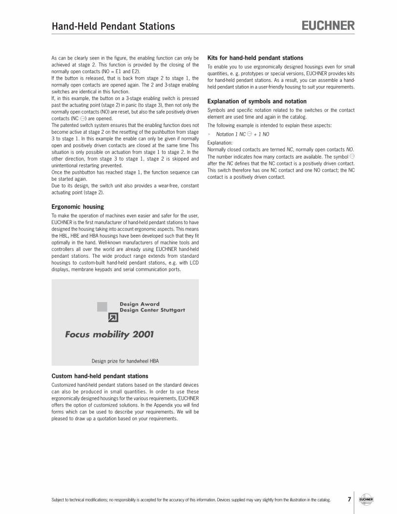
Design prize for handwheel HBA
As can be clearly seen in the figure, the enabling function can only be
achieved at stage 2. This function is provided by the closing of the
normally open contacts (NO = E1 and E2).
If the button is released, that is back from stage 2 to stage 1, the
normally open contacts are opened again. The 2 and 3-stage enabling
switches are identical in this function.
If, in this example, the button on a 3-stage enabling switch is pressed
past the actuating point (stage 2) in panic (to stage 3), then not only the
normally open contacts (NO) are reset, but also the safe positively driven
contacts (NC ) are opened.
The patented switch system ensures that the enabling function does not
become active at stage 2 on the resetting of the pushbutton from stage
3 to stage 1. In this example the enable can only be given if normally
open and positively driven contacts are closed at the same time This
situation is only possible on actuation from stage 1 to stage 2. In the
other direction, from stage 3 to stage 1, stage 2 is skipped and
unintentional restarting prevented.
Once the pushbutton has reached stage 1, the function sequence can
be started again.
Due to its design, the switch unit also provides a wear-free, constant
actuating point (stage 2).
Ergonomic housing
To make the operation of machines even easier and safer for the user,
EUCHNER is the first manufacturer of hand-held pendant stations to have
designed the housing taking into account ergonomic aspects. This means
the HBL, HBE and HBA housings have been developed such that they fit
optimally in the hand. Well-known manufacturers of machine tools and
controllers all over the world are already using EUCHNER hand-held
pendant stations. The wide product range extends from standard
housings to custom-built hand-held pendant stations, e.g. with LCD
displays, membrane keypads and serial communication ports.
Custom hand-held pendant stations
Customized hand-held pendant stations based on the standard devices
can also be produced in small quantities. In order to use these
ergonomically designed housings for the various requirements, EUCHNER
offers the option of customized solutions. In the Appendix you will find
forms which can be used to describe your requirements. We will be
pleased to draw up a quotation based on your requirements.
Kits for hand-held pendant stations
To enable you to use ergonomically designed housings even for small
quantities, e. g. prototypes or special versions, EUCHNER provides kits
for hand-held pendant stations. As a result, you can assemble a hand-
held pendant station in a user-friendly housing to suit your requirements.
Explanation of symbols and notation
Symbols and specific notation related to the switches or the contact
element are used time and again in the catalog.
The following example is intended to explain these aspects:
Notation 1 NC + 1 NO
Explanation:
Normally closed contacts are termed NC, normally open contacts NO.
The number indicates how many contacts are available. The symbol
after the NC defines that the NC contact is a positively driven contact.
This switch therefore has one NC contact and one NO contact; the NC
contact is a positively driven contact.

8
Hand-Held Pendant Stations

9
Hand-Held Pendant Stations
Subject to technical modifications; no responsibility is accepted for the accuracy of this information. Devices supplied may vary slightly from the illustration in the catalog.
Overview of hand-held pendant stations
Features
Version
Hand-held pendant stations
HBA
10ff
Hand-held pendant stations
HBE
18ff
Hand-held pendant stations
HBL
26ff
Selector
switch
Key-
operated
switch
Push-
button
Enabling
switchEMERGENCY
STOP device
Membrane
keypad
LCD
display
RS422
interface,
3964R
protocol
PageHand-
wheel2-st. 3-st.

10
Hand-Held Pendant Stations
Subject to technical modifications; no responsibility is accepted for the accuracy of this information. Devices supplied may vary slightly from the illustration in the catalog.
Hand-held pendant stations HBA
Dimension drawing Handwheel 100 pulses, wear-freemagnetic detent
2 enabling switches, 2-stage, 1 NOcontact each
Depending on version: Tamper-proof EMERGENCY STOP
device according to EN 418,dual-channel
2 selector switches, 5 positions each(X, Y, Z, 4, 5 and 0, 1, 10, 100, 1000)
3 membrane pushbuttons, 1 NOcontact each
Notes
For holder HBA for hand-held pendant stations,
see Accessories page 56
For related 23-pin flange socket, see
Accessories page 50
Technical data
Parameter Value Unit
Housing HBA
Material Plastic
Color Gray RAL 7040
Operating temperature 0 ... +50 °C
Storage temperature -20 ... +50 °C
Degree of protection according to EN 60529 / NEMA IP 65 / 250-12
Connection Coiled cable, expandable to 3.5 m, 23-pin plug connector
Weight Approx. 1.3 kg
Handwheel
Pulses / revolution 100
Power supply 5 ± 5% V DC
Output specifications RS422A
Enabling switch, 2-stage
Switching elements 2, 1 NO contact each
Connection ratings 30 V AC / 0.4 A; 30 V DC / 0.1 A
EMERGENCY STOP device
Standard EN 418
Switching elements 1, 2 NC contacts
Utilization category to IEC 60947-5-1 DC-13, Ue 24 V, Ie 3 A
Selector switch
Output code See wiring diagram
Switching voltage max. 30 V DC
Switching current max. 200 mA
Breaking capacity max. 1 W
Membrane keypad
Switching elements 3, 1 NO contact each
Switching voltage max. 30 V DC
Switching current max. 100 mA
Breaking capacity max. 1 W
160
∅ 85
S2 S3
S1
S4
S5
S6
S8
S7
67
A1
Mountingmagnet
Cable length stretched3500 mm
Plug connector23-pin

11
Hand-Held Pendant Stations
Subject to technical modifications; no responsibility is accepted for the accuracy of this information. Devices supplied may vary slightly from the illustration in the catalog.
Wiring diagram
S1
GHJK
0 V
UB
:+
5 V
+/-
5%
RS 422 A
AB
DEF ABC
B
A
+-A
B
AB
L MNRSTUVWY XZ P
S4S5S6S3 S2
+24 V
olt
S7 DCBA
1 0000 X2 0001 Y3 0011 Z4 0010 4 5 0110 5
S8 DCBA
1 0000 02 0001 1 3 0011 104 0010 100 5 0110 1000
ABCDZ
S7
ABCDZ
S81
5
1
5
Shi
eld
ele
ctr. conn
ecte
d t
o t
he h
and
whe
el
S1:Emergency Stop
S2:Enabling switch left
S3:Enabling switch right
Shi
eld
Gro
und c
onn
ection
Hand
whe
el
A1:
Handwheel
S4:Push button left
S5:Push button middle
S6:Push button right
Conn
ecto
rPC
B
S7:Axle selectionSelector switch left5 positions
S8:Increment selectionSelector switch right5 positions
Gray-CodeGray-Code
A1
Ordering table
Features
Version/item
HBA - 079 828 079 828
HBA - 079 826 079 826
HBA - 072 936 072 936
HBA - 079 827 079 827
* Travel diagramsee page 6
*
*
1
2
2
2 selector switches
5 positions each
S7, S8
3 membrane
pushbuttons
1 NO contact each
S4, S5, S6
2 enabling
switches 2-stage
S2, S3
EMERGENCY
STOP device
S1
Handwheel
100 pulses
A1
Order No.
12
Hand-Held Pendant Stations
Subject to technical modifications; no responsibility is accepted for the accuracy of this information. Devices supplied may vary slightly from the illustration in the catalog.
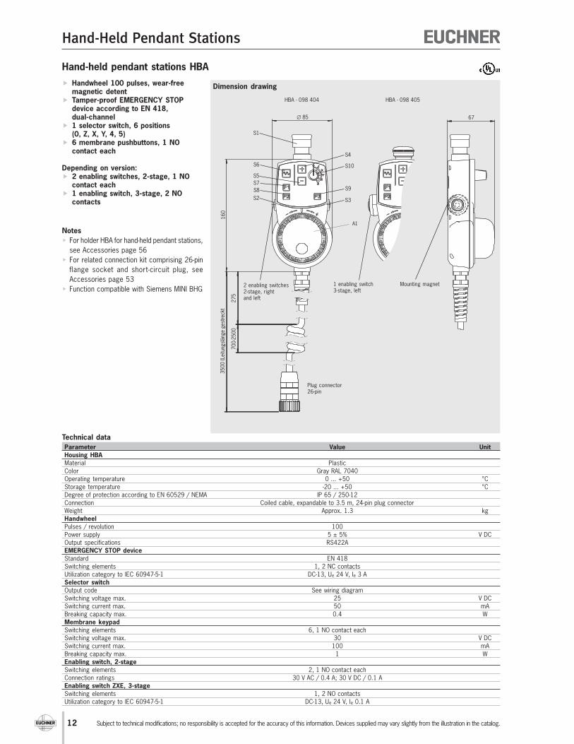
Hand-held pendant stations HBA
Dimension drawing Handwheel 100 pulses, wear-freemagnetic detent
Tamper-proof EMERGENCY STOPdevice according to EN 418,dual-channel
1 selector switch, 6 positions(0, Z, X, Y, 4, 5)
6 membrane pushbuttons, 1 NOcontact each
Depending on version: 2 enabling switches, 2-stage, 1 NO
contact each 1 enabling switch, 3-stage, 2 NO
contacts
Notes
For holder HBA for hand-held pendant stations,
see Accessories page 56
For related connection kit comprising 26-pin
flange socket and short-circuit plug, see
Accessories page 53
Function compatible with Siemens MINI BHG
Technical data
Parameter Value Unit
Housing HBA
Material Plastic
Color Gray RAL 7040
Operating temperature 0 ... +50 °C
Storage temperature -20 ... +50 °C
Degree of protection according to EN 60529 / NEMA IP 65 / 250-12
Connection Coiled cable, expandable to 3.5 m, 24-pin plug connector
Weight Approx. 1.3 kg
Handwheel
Pulses / revolution 100
Power supply 5 ± 5% V DC
Output specifications RS422A
EMERGENCY STOP device
Standard EN 418
Switching elements 1, 2 NC contacts
Utilization category to IEC 60947-5-1 DC-13, Ue 24 V, Ie 3 A
Selector switch
Output code See wiring diagram
Switching voltage max. 25 V DC
Switching current max. 50 mA
Breaking capacity max. 0.4 W
Membrane keypad
Switching elements 6, 1 NO contact each
Switching voltage max. 30 V DC
Switching current max. 100 mA
Breaking capacity max. 1 W
Enabling switch, 2-stage
Switching elements 2, 1 NO contact each
Connection ratings 30 V AC / 0.4 A; 30 V DC / 0.1 A
Enabling switch ZXE, 3-stage
Switching elements 1, 2 NO contacts
Utilization category to IEC 60947-5-1 DC-13, Ue 24 V, Ie 0.1 A
160
∅ 85
S2 S3
S1
S8
S4
S9
S10S6
S7
S5
67
A1
275
700-2
500
3500 (Le
itung
slän
ge
ges
trec
kt
2 enabling switches2-stage, rightand left
Plug connector26-pin
1 enabling switch3-stage, left
Mounting magnet
HBA - 098 404 HBA - 098 405

13
Hand-Held Pendant Stations
Subject to technical modifications; no responsibility is accepted for the accuracy of this information. Devices supplied may vary slightly from the illustration in the catalog.
S1
1234
0 V
UB
:+
5 V
+/-
5%
RS 422 A
AB
22
21
20
18
19
23
+2
4 V
DC
S3 S2S4S5S6S7S8S9
26
S10 CBA
1 110 02 010 Z 3 011 X4 111 Y 5 101 46 001 5
B A
B
A
A
B
16 511
13
14
15
17 6
10 89 7
12
A1
+-
25
24
S2
7 6 5
123
S10:Selector switch right
6 positions
S1:Emergency-stop
S2:Enabling switch2 stageleft
S3:Enabling switch2 stageright
S4: Push button "+"
S5: Push button "-"
S6: Push button "~"
Handwheel
RS422
S7: Push button "F1"
S8: Push button "F2"
S9: Push button "F3"
Shi
eld
Conn
ecto
r PC
B
S2:Enabling switchZXE3 stageleft
Schi
rm
not
conn
ecte
d
ABCZ
S101
6
Gray-Code
Wiring diagram
Ordering table
Features
Version/item
HBA - 098 404 098 404
HBA - 098 405 098 405
* Travel diagramsee page 6
*
1
2
21
2
33
*
*
1
selector switch
6 positions
S10
6
membrane pushbuttons
1 NO contact each
S4, S5, S6, S7, S8, S9
2
enabling
switches
2-stage
S2, S3
1
enabling
switch ZXE
3-stage
S2
EMERGENCY
STOP device
S1
Handwheel
100 pulses
A1
Order No.

14
Hand-Held Pendant Stations
Subject to technical modifications; no responsibility is accepted for the accuracy of this information. Devices supplied may vary slightly from the illustration in the catalog.
Hand-held pendant station HBA - 096 692
Dimension drawing Membrane keypad can be labeledas required using slide-in strips
Tamper-proof EMERGENCY STOPdevice according to EN 418,dual-channel
2 enabling switches, 2-stage, 1 NOcontact each
LEDs white, color customer-specificusing colored keypad membrane
Notes
For holder HBA for hand-held pendant stations,
see Accessories page 56
For related 35-pin flange socket, see
connection components page 50
For template for sl ide-in strips see
www.euchner.de
Technical data
Parameter Value Unit
Housing HBA
Material Plastic
Color Gray RAL 7040
Operating temperature 0 ... +50 °C
Storage temperature -20 ... +50 °C
Degree of protection according to EN 60529 / NEMA IP 65 / 250-12
Connection Coiled cable, expandable to 3.5 m, 24-pin plug connector
Weight Approx. 1.3 kg
EMERGENCY STOP device
Standard EN 418
Switching elements 2 NC contacts
Utilization category to IEC 60947-5-1 DC-13, Ue 24 V, Ie 3 A
Membrane keypad
Switching elements 14, 1 NO contact each
Switching voltage max. 30 V DC
Switching current max. 100 mA
Breaking capacity max. 1 W
Enabling switch, 2-stage
Switching elements 2, 1 NO contact each
Connection ratings 30 V AC / 0.4 A; 30 V DC / 0.1 A
88
0 -
40
00
50
00
Ø
S2
S1
S3
S4
S5S6
S7
S8
S9
S10
S11
S12
S17
S13
S14 S15
S16
<39>
16
0
70
0
85
Mountingmagnet
Plug connector35-pin
(Cable
length
str
etc
hed)

15
Hand-Held Pendant Stations
Subject to technical modifications; no responsibility is accepted for the accuracy of this information. Devices supplied may vary slightly from the illustration in the catalog.
RDBU rtbl
BU
BK sw
VT vt
RD rt
WH ws
GYPK grrs
BN br
GN gn
YE ge
GY gr
PK rs
GNWH wsgn
A
B
C
D
E
F
G
H
J
K
L
M
N
Y
Z
a
b
c
BNBU brbl
RDWH wsrt
BNRD brrt
BKWH wssw
BKBN brsw
BNGN brgn
YEWH wsge
BNYE gebr
GYWH wsgr
BNGY grbr
P
R
S
T
U
d
e
f
g
h
i
GNGY grgn
YEGY gegr
GNPK rsgn
YEPK gers
GNBU gnbl
YEBU gebl
WHPK wsrs
BNPK rsbr
BUWH wsbl
V
W
X
j
k
m
RDGN gnrt
RDYE gert
BKGN gnsw
bl
H5
H4
H6
H7
H8
H9
DC +24V
H10
H11
H12
H13
H14
H15
H16
H17
4
S9
S10
4 3
4 3
S11
S12
4 3
4 3
S13
S14
4 3
4 3
S15
S16
4 3
4 3
S17
S4
4 3
4 3
S5
4 3
4 3
S7
S8
4 3
3
S6
S1
S34 3
S24 3
1
2
1
2
Ordering table
Item Order No.
Hand-held pendant station HBA - 096 692 with:
Membrane keypad that can be labeled as required
Tamper-proof EMERGENCY STOP device according to EN 418, dual-channel 096 692
2 enabling switches, 2-stage, 1 NO contact each
LEDs white, color customer-specific using colored keypad membrane
Wiring diagram
S1:EMERGENCY STOP
S2:Enabling switch left *
S3:Enabling switch right *
S4 - S17:Membrane keypad
Screen
35-pin plug connector
All cores 0.14 mm²
* Travel diagramsee page 6
1
2
2

16
Hand-Held Pendant Stations
Subject to technical modifications; no responsibility is accepted for the accuracy of this information. Devices supplied may vary slightly from the illustration in the catalog.
85
160
S3S2
S1
38,5
Hand-held pendant stations HBAS
Dimension drawing Programmable pulse generator Tamper-proof EMERGENCY STOP
device according to EN 418,dual-channel
Membrane keypad with 20 keys and2 LEDs
LCD display with LED backgroundlighting, switchable 4-line/8-columnor 8-line/16-column
RS422 interface, 3964R protocol
Depending on version: 2 enabling switches, 2-stage, 1 NO
contact each 1 enabling switch, 3-stage, 2 NO
contacts
Notes
For holder HBA for hand-held pendant stations,
see Accessories page 56
For related 19-pin flange socket, see
Accessories page 53
ActiveX modules available for integrating the
user’s application (for MS Windows®-based
user programs with ActiveX support)
Technical data
Parameters Value Unit
Housing HBA
Material Plastic
Color Gray RAL 7040
Operating temperature 0 ... +50 °C
Storage temperature -20 ... +50 °C
Degree of protection according to EN 60529 / NEMA IP 65 / 250-12
Connection Coiled cable, expandable to 3.5 m, 19-pin plug connector
Weight Approx. 0.85 kg
Pulse generator
Pulses Programmable
Output specifications RS422A
EMERGENCY STOP device
Standard EN 418
Switching elements 1, 2 NC contacts
Utilization category to IEC 60947-5-1 DC-13, Ue 24 V, Ie 3 A A
Communications interface
Type Serial, RS422A (4-wire)
Data format 8 data bits + 1 parity bit (even), 1 stop bit
Transfer speed 9600 or 19200 baud, automatic detection
Transfer protocol 3964R
Electrical connection
Power supply 24 ± 20% V DC
Operating current, max. 100 mA
Enabling switch, 2-stage
Switching elements 2, 1 NO contact each
Switching voltage max. 30 V DC
Switching current max. 0.1 A
Enabling switch ZXE, 3-stage
Switching elements 1, 2 NO contacts
Utilization category to IEC 60947-5-1 DC-13, Ue 24 V, Ie 0.1 A
1) Approval pending
Cable length stretched3500 mm
Plug connector19-pin
2 enabling switches2-stage, rightand left
1 enabling switch3-stage, left
HBAS - 072 949 HBAS - 094 594
Mounting magnet
1)

17
Hand-Held Pendant Stations
Subject to technical modifications; no responsibility is accepted for the accuracy of this information. Devices supplied may vary slightly from the illustration in the catalog.
13
2E1
E2
S2
16
18
19
S1
11
14
13
+2
4 V
0 V
4 315 179
RX
RX
TX
TX
10 8
AA
PO
WER
STA
TU
S
25B
6B
1217
S3
18
19
S2
16
17
S2:Enablingswitch ZXE3 stageleft
S3:Enablingswitch2 stageright
S1:Emergency Stop
PowerSupply
Microcontroller
Display
Shie
ld
CommunicationInterface RS422
Pulse GeneratorRS422
Keyp
ad
Program-memory FLASH
Shie
ld e
lectr.c
onne
cte
d to
the p
lug c
onne
cto
r housing
Interface
S2:Enablingswitch2 stageleft
Display-memoryRAM
Wiring diagram
Ordering table
Version/item
HBAS - 072 949 072 949
HBAS - 094 594
094 594
ActiveX modules
Software for integration into user software that supports ActiveX093 011
Manual ActiveX modules
Detailed documentation on use of the software093 013
* Travel diagramsee page 6
*
1
2
33
2
enabling switches
2-stage
S2, S3
1
enabling switch
ZXE, 3-stage
S2
EMERGENCY
STOP device
S1
Programmable pulse generator,
membrane keypad, display,
RS422 interface, 3964R protocol
Order No.
Features
18
Hand-Held Pendant Stations
Subject to technical modifications; no responsibility is accepted for the accuracy of this information. Devices supplied may vary slightly from the illustration in the catalog.
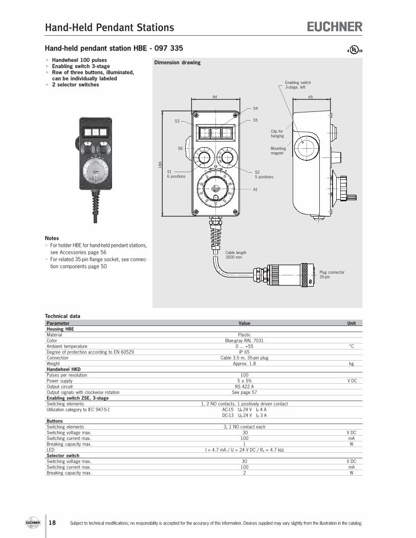
Hand-held pendant station HBE - 097 335
Dimension drawing Handwheel 100 pulses Enabling switch 3-stage Row of three buttons, illuminated,
can be individually labeled 2 selector switches
Technical data
Parameter Value Unit
Housing HBE
Material Plastic
Color Blue-gray RAL 7031
Ambient temperature 0 ... +55 °C
Degree of protection according to EN 60529 IP 65
Connection Cable 3.5 m, 35-pin plug
Weight Approx. 1.8 kg
Handwheel HKD
Pulses per revolution 100
Power supply 5 ± 5% V DC
Output circuit RS 422 A
Output signals with clockwise rotation See page 57
Enabling switch ZSE, 3-stage
Switching elements 1, 2 NO contacts, 1 positively driven contact
Utilization category to IEC 947-5-1 AC-15 Ue 24 V Ie 4 A
DC-13 Ue 24 V Ie 3 A
Buttons
Switching elements 3, 1 NO contact each
Switching voltage max. 30 V DC
Switching current max. 100 mA
Breaking capacity max. 1 W
LED I = 4.7 mA / U = 24 V DC / Rv = 4.7 kΩ
Selector switch
Switching voltage max. 30 V DC
Switching current max. 100 mA
Breaking capacity max. 2 W
Notes
For holder HBE for hand-held pendant stations,
see Accessories page 56
For related 35-pin flange socket, see connec-
tion components page 50
184
84 65
Mountingmagnet
Cable length3500 mm
Enabling switch3-stage, left
Clip forhanging
S4
S5
S25 positions
S3
S16 positions
Plug connector35-pin
A1
S6
19
Hand-Held Pendant Stations
Subject to technical modifications; no responsibility is accepted for the accuracy of this information. Devices supplied may vary slightly from the illustration in the catalog.
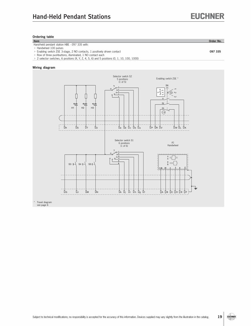
Wiring diagram
Ordering table
Item Order No.
Hand-held pendant station HBE - 097 335 with:
Handwheel 100 pulses
Enabling switch ZSE 3-stage, 2 NO contacts, 1 positively driven contact 097 335
Row of three pushbuttons, illuminated, 1 NO contact each
2 selector switches, 6 positions (X, Y, Z, 4, 5, 6) and 5 positions (0, 1, 10, 100, 1000)
* Travel diagramsee page 6
H S T U e d c b a P R V W L K
G J M N k j i h g f A B C D E F
A
A
B
B
H1 H2 H3
S6
S3 S4 S5
Selector switch S25 positions
(1 of 5)
Selector switch S16 positions
(1 of 6)
Enabling switch ZSE *
A1Handwheel
1
2
33

20
Hand-Held Pendant Stations
Subject to technical modifications; no responsibility is accepted for the accuracy of this information. Devices supplied may vary slightly from the illustration in the catalog.
Hand-held pendant station HBE - 097 336
Dimension drawing Handwheel 100 pulses Tamper-proof EMERGENCY STOP
device according to EN 418,dual-channel
2 enabling switches 2-stage Row of three pushbuttons, illuminated,
can be individually labeled 2 selector switches
Technical data
Parameters Value Unit
Housing HBE
Material Plastic
Color Blue-gray RAL 7031
Ambient temperature 0 ... +55 °C
Degree of protection according to EN 60529 IP 65
Connection Cable 3.5 m, 35-pin plug
Weight Approx. 1.8 kg
Handwheel HKD
Pulses per revolution 100
Power supply 5 ± 5% V DC
Output circuit RS 422 A
Output signals with clockwise rotation See page 57
EMERGENCY STOP device
Standard EN 418
Switching elements 1, 2 NC contacts
Utilization category to IEC 60947-5-1 DC-13, Ue 24 V, Ie 2.75 A
Enabling switch ZSG, 2-stage
Switching elements 2, 1 NO contact each
Utilization category to IEC 947-5-1 AC-15 Ue 24 V Ie 4 A
DC-13 Ue 24 V Ie 3 A
Buttons
Switching elements 3, 1 NO contact each
Switching voltage max. 30 V DC
Switching current max. 100 mA
Breaking capacity max. 1 W
LED I = 4.7 mA / U = 24 V DC / Rv = 4.7 kW
Selector switch
Switching voltage max. 30 V DC
Switching current max. 100 mA
Breaking capacity max. 2 W
Notes
For holder HBE for hand-held pendant stations,
see Accessories page 56
For related 35-pin flange socket, see connec-
tion components page 50
18
4
84 65
Mountingmagnet
Cable length3500 mm
Enabling switch2-stage, on bothsides
Clip forhanging
S4 (H2)
S5 (H3)
S25 positions
S3 (H1)
S16 positions
Plug connector35-pin
A1
S6 S7

21
Hand-Held Pendant Stations
Subject to technical modifications; no responsibility is accepted for the accuracy of this information. Devices supplied may vary slightly from the illustration in the catalog.
Wiring diagram
Ordering table
Item Order No.
Hand-held pendant station HBE - 097 336 with:
Handwheel 100 pulses
Tamper-proof emergency stop device according to EN 418, dual-channel
2 enabling switches ZSG 2-stage, 1 NO contact each097 336
Row of three buttons, illuminated, 1 NO contact each
2 selector switches, 6 positions (X, Y, Z, 4, 5, 6) and 5 positions (0, 1, 10, 100, 1000)
H S T U e d c b a V P R W K L
G J M N k j i h g f A B C D E F
A
A
B
B
H1 H2 H3
S8
S3 S4 S5
S7
S6
Selector switch S25 positions
(1 of 5)
Selector switch S16 positions
(1 of 6)
A1Handwheel
EMERGENCY STOP 2 enabling switchesZSG *
* Travel diagramsee page 6
1
2
2

22
Hand-Held Pendant Stations
Subject to technical modifications; no responsibility is accepted for the accuracy of this information. Devices supplied may vary slightly from the illustration in the catalog.
Hand-held pendant station HBE - 097 337
Dimension drawing Handwheel 100 pulses Enabling switch 3-stage 9 illuminated buttons Buttons can be designed as required
using slide-in film
Technical data
Parameters Value Unit
Housing HBE
Material Plastic
Color Blue-gray RAL 7031
Ambient temperature 0 ... +55 °C
Degree of protection according to EN 60529 IP 65
Connection Cable 3.5 m, 35-pin plug
Weight Approx. 1.8 kg
Handwheel HKD
Pulses per revolution 100
Power supply 5 ± 5% V DC
Output circuit RS 422 A
Output signals See page 57
Enabling switch ZSE, 3-stage
Switching elements 1, 2 NO contacts, 1 positively driven contact
Utilization category to IEC 947-5-1 AC-15 Ue 24 V Ie 4 A
DC-13 Ue 24 V Ie 3 A
Buttons
Switching elements 9, 1 NO contact each
Switching voltage max. 30 V DC
Switching current max. 100 mA
Breaking capacity max. 2 W
LED I = 14.5 mA / U = 24 V DC / Rv = 1.4 kW
Notes
For holder HBE for hand-held pendant stations,
see Accessories page 56
For related 35-pin flange socket, see connec-
tion components page 50
184
84 65
Mountingmagnet
Cable length3500 mm
Enabling switch3-stage, left
Clip forhanging
Buttons
S1
Plug connector35-pin
A1
S3
S9
S10
23
Hand-Held Pendant Stations
Subject to technical modifications; no responsibility is accepted for the accuracy of this information. Devices supplied may vary slightly from the illustration in the catalog.
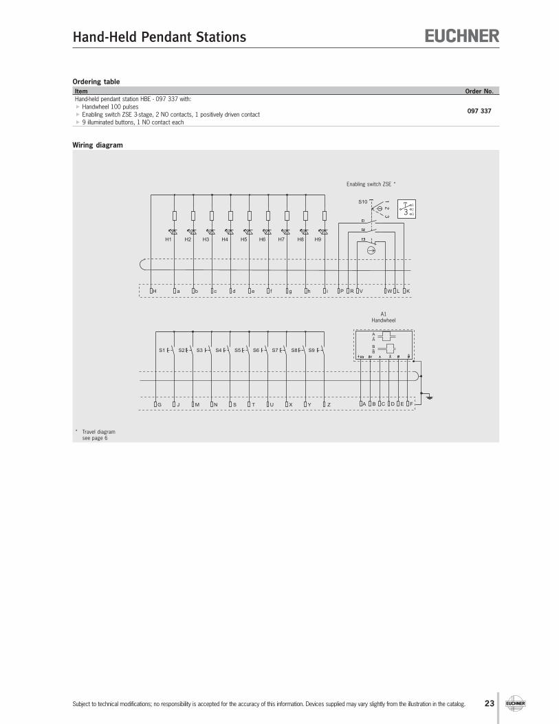
Wiring diagram
Ordering table
Item Order No.
Hand-held pendant station HBE - 097 337 with:
Handwheel 100 pulses
Enabling switch ZSE 3-stage, 2 NO contacts, 1 positively driven contact097 337
9 illuminated buttons, 1 NO contact each
* Travel diagramsee page 6
H a b c d e f g h i P R V W L K
G J M N S T U X Y Z A B C D E F
A
A
B
B
H1 H2 H3 H4 H5 H6 H7 H8 H9
S10
S1 S2 S3 S4 S5 S6 S7 S8 S9
Enabling switch ZSE *
A1Handwheel
1
2
33
24
Hand-Held Pendant Stations
Subject to technical modifications; no responsibility is accepted for the accuracy of this information. Devices supplied may vary slightly from the illustration in the catalog.
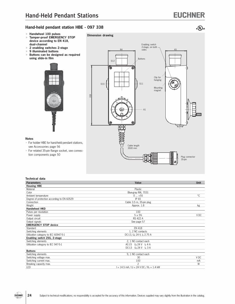
Hand-held pendant station HBE - 097 338
Handwheel 100 pulses Tamper-proof EMERGENCY STOP
device according to EN 418,dual-channel
2 enabling switches 2-stage 9 illuminated buttons Buttons can be designed as required
using slide-in film
Technical data
Parameters Value Unit
Housing HBE
Material Plastic
Color Blue-gray RAL 7031
Ambient temperature 0 ... +55 °C
Degree of protection according to EN 60529 IP 65
Connection Cable 3.5 m, 35-pin plug
Weight Approx. 1.8 kg
Handwheel HKD
Pulses per revolution 100
Power supply 5 ± 5% V DC
Output circuit RS 422 A
Output signals See page 57
EMERGENCY STOP device
Standard EN 418
Switching elements 1, 2 NC contacts
Utilization category to IEC 60947-5-1 DC-13, Ue 24 V, Ie 2.75 A
Enabling switch ZSG, 2-stage
Switching elements 2, 1 NO contact each
Utilization category to IEC 947-5-1 AC-15 Ue 24 V Ie 4 A
DC-13 Ue 24 V Ie 3 A
Buttons
Switching elements 9, 1 NO contact each
Switching voltage max. 30 V DC
Switching current max. 100 mA
Breaking capacity max. 2 W
LED I = 14.5 mA / U = 24 V DC / Rv = 1.4 kW
Notes
For holder HBE for hand-held pendant stations,
see Accessories page 56
For related 35-pin flange socket, see connec-
tion components page 50
Dimension drawing
18
4
84 65
Mountingmagnet
Cable length3500 mm
Clip forhanging
Buttons
Plug connector35-pin
A1
S10 S11
Enabling switch2-stage, on bothsides
S12

25
Hand-Held Pendant Stations
Subject to technical modifications; no responsibility is accepted for the accuracy of this information. Devices supplied may vary slightly from the illustration in the catalog.
Wiring diagram
Ordering table
Item Order No.
Hand-held pendant station HBE - 097 338 with:
Handwheel 100 pulses
Tamper-proof emergency stop device according to EN 418, dual-channel 097 338
2 enabling switches ZSG 2-stage, 1 NO contact each
9 illuminated buttons, 1 NO contact each
H a b c d e f g h i V P R W K L
G J M N S T U X Y Z A B C D E F
A
A
B
B
H1 H2 H3 H4 H5 H6 H7 H8 H9
S10
S1 S2 S3 S4 S5 S6 S7 S8 S9
S11
S12
A1Handwheel
EMERGENCY STOP 2 enablingswitches ZSG *
* Travel diagramsee page 6
1
2
2

26
Hand-Held Pendant Stations
Subject to technical modifications; no responsibility is accepted for the accuracy of this information. Devices supplied may vary slightly from the illustration in the catalog.
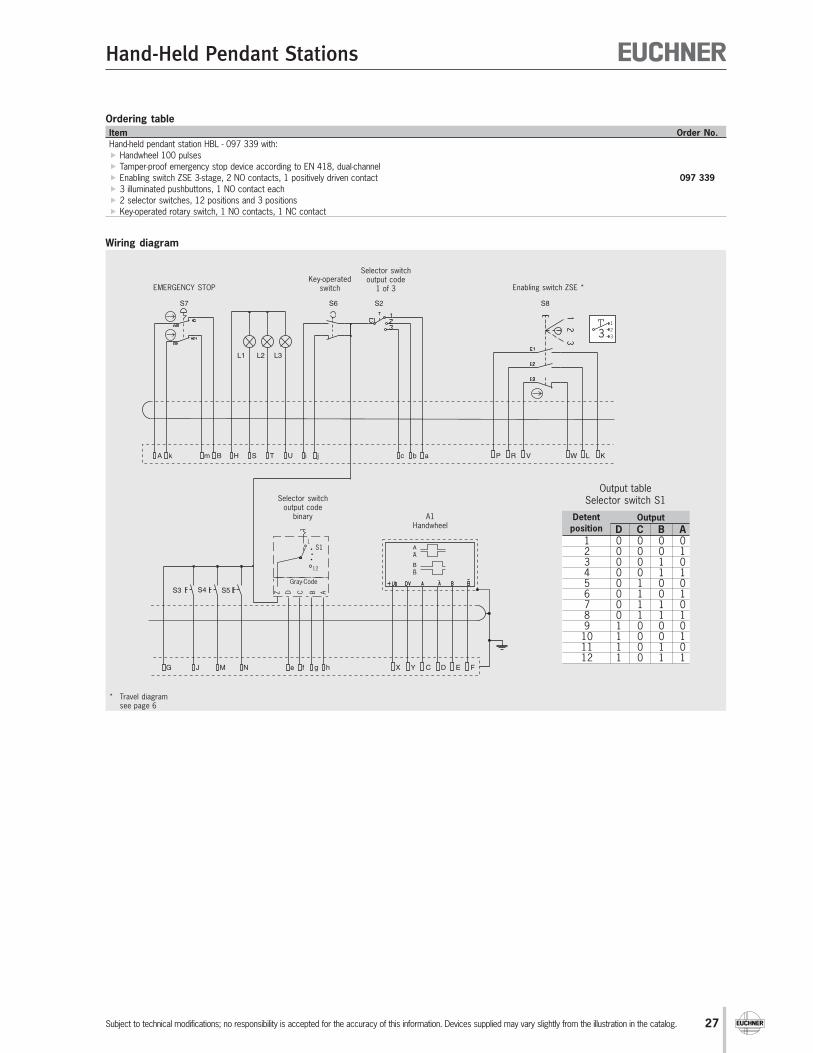
Hand-held pendant station HBL - 097 339
Handwheel 100 pulses Tamper-proof EMERGENCY STOP
device according to EN 418,dual-channel
Enabling switch 3-stage 3 illuminated pushbuttons, can be
individually labeled 2 selector switches Key-operated switch
Technical data
Parameters Value Unit
Housing HBL
Material Plastic
Color Blue-gray RAL 7031
Ambient temperature 0 ... +55 °C
Degree of protection according to EN 60529 IP 65
Connection Cable 3.5 m, 35-pin plug
Weight Approx. 2.1 kg
EMERGENCY STOP device
Standard EN 418
Switching elements 1, 2 NC contacts
Utilization category to IEC 947-5-1 DC-13 Ue 24 V Ie 2.75 A
Handwheel HKD
Pulses per revolution 100
Power supply 5 ± 5% V DC
Output circuit RS 422 A
Output signals See page 57
Enabling switch ZSE, 3-stage
Switching elements 1, 2 NO contacts, 1 positively driven contact
Utilization category to IEC 947-5-1 AC-15 Ue 24 V Ie 4 A
DC-13 Ue 24 V Ie 3 A
Buttons
Switching elements 3, 1 NO contact each
Switching voltage max. 30 V DC
Switching current max. 200 mA
Incandescent lamp I = 21 mA / U = 24 V DC
Selector switch
Switching voltage max. 30 V DC
Switching current max. 100 mA
Breaking capacity max. 2 W
Key-operated switch
Switching voltage max. 30 V DC
Switching current max. 250 mA
Notes
For holder HBL for hand-held pendant stations,
see Accessories page 56
For related 35-pin flange socket, see connec-
tion components page 50
Dimension drawing
77
120
114
25
2
Mountingmagnet
Cable length3500 mm
Clip forhanging
S3
Plug connector35-pin
A1
S23 positions
S6
S8Enabling switch3-stage, left
S7
S4 S5
S112positions
L1 L2 L3
27
Hand-Held Pendant Stations
Subject to technical modifications; no responsibility is accepted for the accuracy of this information. Devices supplied may vary slightly from the illustration in the catalog.
Wiring diagram
Ordering table
Item Order No.
Hand-held pendant station HBL - 097 339 with:
Handwheel 100 pulses
Tamper-proof emergency stop device according to EN 418, dual-channel
Enabling switch ZSE 3-stage, 2 NO contacts, 1 positively driven contact 097 339
3 illuminated pushbuttons, 1 NO contact each
2 selector switches, 12 positions and 3 positions
Key-operated rotary switch, 1 NO contacts, 1 NC contact
P R V W L K
X Y C D E F
A
A
B
B
A k m B H S T U i j c b a
G J M N fe g h
S7
L1 L2 L3
S6 S2 S8
S3 S5S4 ABCDZ
S11
12
Gray-Code
Enabling switch ZSE *
A1Handwheel
EMERGENCY STOPKey-operated
switch
Selector switchoutput code
1 of 3
Selector switchoutput code
binary Output
D C B A1 0 0 0 02 0 0 0 13 0 0 1 04 0 0 1 15 0 1 0 06 0 1 0 17 0 1 1 08 0 1 1 19 1 0 0 0
10 1 0 0 111 1 0 1 012 1 0 1 1
Output tableSelector switch S1
1
2
33
* Travel diagramsee page 6
Detent
position
28
Hand-Held Pendant Stations
Subject to technical modifications; no responsibility is accepted for the accuracy of this information. Devices supplied may vary slightly from the illustration in the catalog.
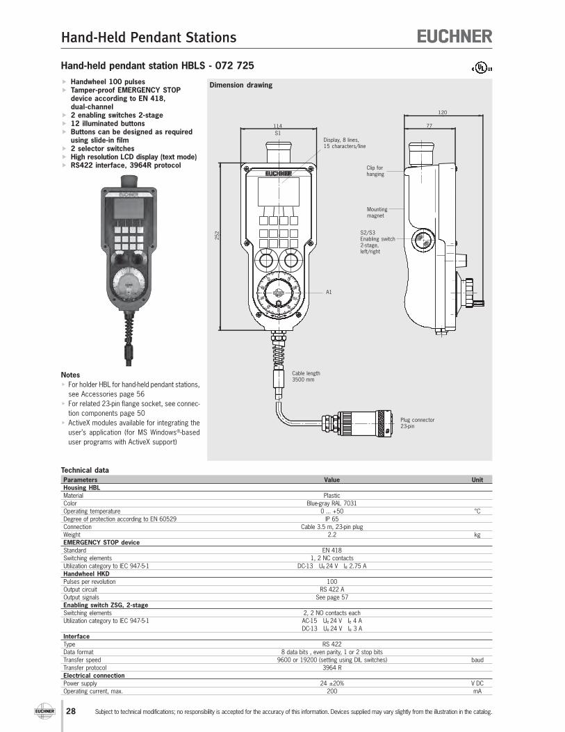
Hand-held pendant station HBLS - 072 725
Handwheel 100 pulses Tamper-proof EMERGENCY STOP
device according to EN 418,dual-channel
2 enabling switches 2-stage 12 illuminated buttons Buttons can be designed as required
using slide-in film 2 selector switches High resolution LCD display (text mode) RS422 interface, 3964R protocol
Technical data
Parameters Value Unit
Housing HBL
Material Plastic
Color Blue-gray RAL 7031
Operating temperature 0 ... +50 °C
Degree of protection according to EN 60529 IP 65
Connection Cable 3.5 m, 23-pin plug
Weight 2.2 kg
EMERGENCY STOP device
Standard EN 418
Switching elements 1, 2 NC contacts
Utilization category to IEC 947-5-1 DC-13 Ue 24 V Ie 2.75 A
Handwheel HKD
Pulses per revolution 100
Output circuit RS 422 A
Output signals See page 57
Enabling switch ZSG, 2-stage
Switching elements 2, 2 NO contacts each
Utilization category to IEC 947-5-1 AC-15 Ue 24 V Ie 4 A
DC-13 Ue 24 V Ie 3 A
Interface
Type RS 422
Data format 8 data bits , even parity, 1 or 2 stop bits
Transfer speed 9600 or 19200 (setting using DIL switches) baud
Transfer protocol 3964 R
Electrical connection
Power supply 24 ±20% V DC
Operating current, max. 200 mA
Notes
For holder HBL for hand-held pendant stations,
see Accessories page 56
For related 23-pin flange socket, see connec-
tion components page 50
ActiveX modules available for integrating the
user’s application (for MS Windows®-based
user programs with ActiveX support)
Dimension drawing
77
120
114
25
2
Mountingmagnet
Cable length3500 mm
Clip forhanging
Plug connector23-pin
A1
Display, 8 lines,15 characters/line
S2/S3Enabling switch2-stage,left/right
S1

29
Hand-Held Pendant Stations
Subject to technical modifications; no responsibility is accepted for the accuracy of this information. Devices supplied may vary slightly from the illustration in the catalog.
Wiring diagram
Ordering table
Item Order No.
Hand-held pendant station HBLS - 072 725 with:
Handwheel 100 pulses
Tamper-proof emergency stop device according to EN 418, dual-channel
2 enabling switches ZSG 2-stage, 2 NO contacts each072 725
12 illuminated buttons
2 selector switches, 12 positions each
A B BA
A
B
A
B
+UB 0 Volt
RX TX
HA BC D E F J G PRV WN KL
NRX
M
NTX
S
96 1 58 10 3 72 4
A1
S2
S3
S1
Handwheel A05 ( RS422A)
Enabling Switche ZSG *
Powersupply ri
ght
Serial communication interfaceRS422
E-Stop
Control Panel
Shield electr. connected to the plug connector housing
left
Shi
eld
Microcontroller
* Travel diagramsee page 6
1
2
2
ActiveX modules
Software for integration into user software that supports ActiveX067 176
Manual ActiveX modules
Detailed documentation on use of the software067 178

30
Hand-Held Pendant Stations
Subject to technical modifications; no responsibility is accepted for the accuracy of this information. Devices supplied may vary slightly from the illustration in the catalog.
31
Kit for Hand-Held Pendant Stations HBA
Subject to technical modifications; no responsibility is accepted for the accuracy of this information. Devices supplied may vary slightly from the illustration in the catalog.
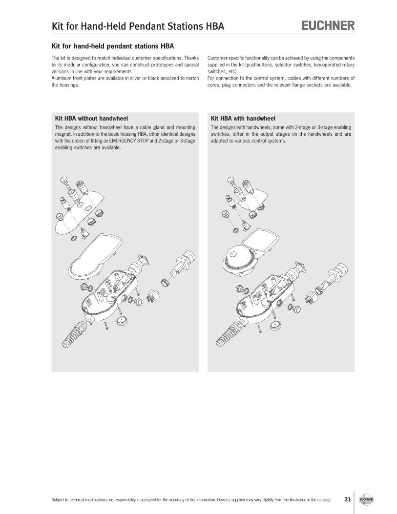
Kit for hand-held pendant stations HBA
The kit is designed to match individual customer specifications. Thanks
to its modular configuration, you can construct prototypes and special
versions in line with your requirements.
Aluminum front plates are available in silver or black anodized to match
the housings.
Customer-specific functionality can be achieved by using the components
supplied in the kit (pushbuttons, selector switches, key-operated rotary
switches, etc).
For connection to the control system, cables with different numbers of
cores, plug connectors and the relevant flange sockets are available.
Kit HBA with handwheel
The designs with handwheels, some with 2-stage or 3-stage enabling
switches, differ in the output stages on the handwheels and are
adapted to various control systems.
Kit HBA without handwheel
The designs without handwheel have a cable gland and mounting
magnet. In addition to the basic housing HBA, other identical designs
with the option of fitting an EMERGENCY STOP and 2-stage or 3-stage
enabling switches are available.

32
Kit for Hand-Held Pendant Stations HBA
Subject to technical modifications; no responsibility is accepted for the accuracy of this information. Devices supplied may vary slightly from the illustration in the catalog.
Housing HBA without handwheel
Dimension drawing
Technical data
Parameter Value Unit
Housing HBA
Material Plastic
Color Gray RAL 7040
Operating temperature 0 ... +50 °C
Storage temperature -20 ... +50 °C
Degree of protection according to EN 60529 / NEMA IP 65 / 250-12
Weight 0.3 kg
Enabling switch, 2-stage
Switching elements 2, 1 NO contact each
Connection ratings AC 30 V / 0.4 A; DC 30 V / 0.1 A
Enabling switch ZXE, 3-stage
Switching elements 2 NO contacts
Utilization category to IEC 60947-5-1 DC-13, Ue 24 V, Ie 0.1 A
Cable gland for cable diameter 5-10 mm Rubber-coated mounting magnet on
the rear of housing 6 fixing points for printed circuit board
in top shell
Depending on version: Hole for EMERGENCY STOP device
(sealed with blanking plug) 2 enabling switches, 2-stage,
1 NO contact each 1 enabling switch, 3-stage,
2 NO contacts
Notes
Matching front plate, see page 36
Matching EMERGENCY STOP device (rotary
or pull release) see page 46
Attention: housing HBA - 095 562 only
suitable for EMERGENCY STOP device with
rotary release.
Depending on version with two 2-stage
enabling switches or one 3-stage enabling
switch.
160
∅ 85
S1 S2
38,5
Blanking plug in holefor EMERGENCY STOP device
Mounting magnet
Cable glandenclosed
Enabling switch3-stage
Topshell
HousingHBA - 084 450HBA - 086 155
HousingHBA- 095 562
For dimensions of EMERGENCY STOP devices see page 42

33
Kit for Hand-Held Pendant Stations HBA
Subject to technical modifications; no responsibility is accepted for the accuracy of this information. Devices supplied may vary slightly from the illustration in the catalog.
4
3
S1
4
3
S2
2
1
S1
4
31 2 3
1
2
2
1
2
33
* Travel diagramsee page 6
Ordering table
Features
Housing HBA - 084 445084 445
(without hole, without enabling switch)
Housing HBA - 084 450 for EMERGENCY STOP 084 450
with pull release
Housing HBA - 086 155 for EMERGENCY STOP 086 155
with pull release
Housing HBA - 095 562 for EMERGENCY STOP 095 562
with rotary release
Hole for
EMERGENCY STOP device
2 enabling switches*,
2-stage,
1 NO contact each
S1, S2
1 enabling switch ZXE*,
3-stage,
2 NO contacts
S1
Order No.Version/item

34
Kit for Hand-Held Pendant Stations HBA
Subject to technical modifications; no responsibility is accepted for the accuracy of this information. Devices supplied may vary slightly from the illustration in the catalog.
Housing HBA with handwheel
Technical data
Parameter Value Unit
Housing HBA
Material Plastic
Color Gray RAL 7040
Operating temperature 0 ... +50 °C
Storage temperature -20 ... +50 °C
Degree of protection according to EN 60529 /NEMA IP 65 / 250-12
Weight 0.3 kg
Enabling switch, 2-stage
Switching elements 2, 1 NO contact each
Utilization category to IEC 60947-5-1 30 V AC / 0.4 A; 30 V DC / 0.1 A
Enabling switch ZXE, 3-stage
Switching elements 1, 2 NO contacts
Utilization category to IEC 60947-5-1 DC-13, Ue 24 V, Ie 0.1 A
Handwheel RS422A (UB = 5 V DC)
Pulses / revolution 100
Power supply 5 ± 5% V DC
Output specifications RS422A
Handwheel push-pull 5 V (UB = 10...30 V DC)
Pulses / revolution 25
Power supply 10 ... 30 V DC
Output circuit 5 V push-pull
Output voltage / output current HIGH, min. 4.9 V at 0 mA / 3.9 V at 5 mA / 3.6 V at 20 mA
LOW, max. 1.3 V at 15 mA
Handwheel push-pull 24 V (UB = 10...30 V DC)
Pulses / revolution 100
Power supply 10 ... 30 V DC
Output circuit Push-pull 24 V
Output voltage / output current HIGH, min. UB - 3 V at 20 mA
LOW, max. 3 V at 20 mA
Handwheel push-pull 5 V (UB = 5 V DC)
Pulses / revolution 100
Power supply 5 ± 5% V DC
Output circuit 5 V push-pull
Output voltage / output current HIGH, min. 4.0 V at 0 mA / 3.4 V at 5 mA / 3.0 V at 20 mA
LOW, max. 1.3 V at 15 mA
Handwheel 100 pulses, wear-freemagnetic detent
Hole for EMERGENCY STOP device(sealed with blank plug)
Cable gland for cable diameter 5-10 mm Rubber-coated mounting magnet on
the rear of housing 6 fixing points for printed circuit board
in top shell
Depending on version: 2 enabling switches, 2-stage, 1 NO
contact each 1 enabling switch, 3-stage, 2 NO contacts Various handwheel output stages
Notes
Matching front plate, see page 36
Matching EMERGENCY STOP device (rotary
or pull release) see page 46
Warning:
Housing HBA - 095 561, HBA - 095 573,
HBA - 095 572 and HBA - 095 574 only suitable
for EMERGENCY STOP device with rotary
release.
Depending on version with two 2-stage
enabling switches or one 3-stage enabling
switch.
Dimension drawing
160
S1 S2
67∅ 85
Blanking plug in holefor EMERGENCY STOP device
Mounting
magnet
Cable glandenclosed
Enabling switch3-stage
Topshell
A1
HousingHBA - 083 449HBA - 083 499HBA - 083 495HBA - 086 762
HousingHBA - 095 561HBA - 095 573HBA - 095 572HBA - 095 574
For dimensions of EMERGENCY STOP devices see page 46
35
Kit for Hand-Held Pendant Stations HBA
Subject to technical modifications; no responsibility is accepted for the accuracy of this information. Devices supplied may vary slightly from the illustration in the catalog.
4
3
S1
4
3
S2
2
1
S1
4
31 2 3
1
2
2
1
2
33
* Travel diagramsee page 6
UB
B
/A
/B
A
RS
42
2 A
A
B
/B
/A
+-
+-
0 V
UB
Shield
A1HandwheelRS422A
0 V
UB
B
A A
B
+-
+-
pus
h pul
l
Shield
A1Handwheelpush pull
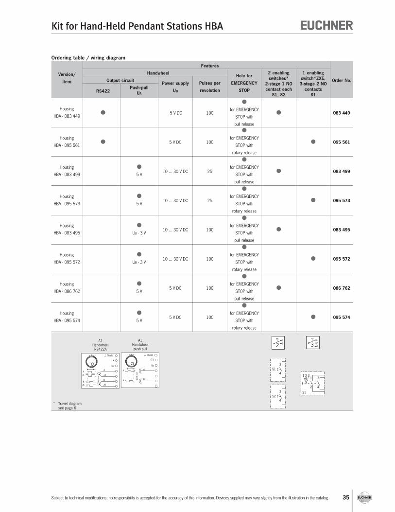
Ordering table / wiring diagram
Features
Handwheel
Output circuit Order No.
RS422
Housing
5 V DC 100
for EMERGENCY 083 449
HBA - 083 449 STOP with
pull release
Housing 5 V DC 100
for EMERGENCY 095 561
HBA - 095 561 STOP with
rotary release
Housing 10 ... 30 V DC 25
for EMERGENCY 083 499
HBA - 083 499 5 V STOP with
pull release
Housing 10 ... 30 V DC 25
for EMERGENCY 095 573
HBA - 095 573 5 V STOP with
rotary release
Housing 10 ... 30 V DC 100
for EMERGENCY 083 495
HBA - 083 495 UB - 3 V STOP with
pull release
Housing 10 ... 30 V DC 100
for EMERGENCY 095 572
HBA - 095 572 UB - 3 V STOP with
rotary release
Housing 5 V DC 100
for EMERGENCY 086 762
HBA - 086 762 5 V STOP with
pull release
Housing 5 V DC 100
for EMERGENCY 095 574
HBA - 095 574 5 V STOP with
rotary release
Version/
item Power supply
UB
Pulses per
revolution
Hole for
EMERGENCY
STOP
2 enabling
switches*
2-stage 1 NO
contact each
S1, S2
1 enabling
switch*ZXE,
3-stage 2 NO
contacts
S1
Push-pull
UA

36
Kit for Hand-Held Pendant Stations HBA
Subject to technical modifications; no responsibility is accepted for the accuracy of this information. Devices supplied may vary slightly from the illustration in the catalog.
Dimension drawing
Front plates for housing HBA with and without handwheel
Notes
Matches housing HBA (see page 32 and
page 34)
0,5
69,4
63,9
Rear self-adhesivecoated
∅ 67,4
69,4
142,4
0,5
Rear self-adhesivecoated
For housing HBAwithout handwheel
For housing HBAwith handwheel
Technical data
Material
Front plateElectrically anodized aluminum, black or silver
Self-adhesive coating on rear
Ordering table
Item Order No.
Front plate for housing HBA without handwheel, silver anodized 084 395
Front plate for housing HBA without handwheel, black anodized 084 396
Front plate for housing HBA with handwheel, silver anodized 083 635
Front plate for housing HBA with handwheel, black anodized 083 636
37
Kit for Hand-Held Pendant Stations HBE
Subject to technical modifications; no responsibility is accepted for the accuracy of this information. Devices supplied may vary slightly from the illustration in the catalog.
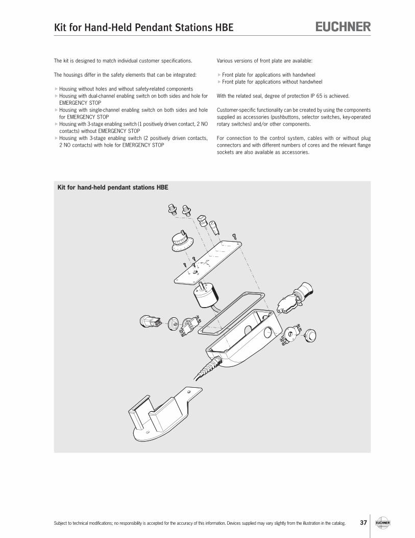
The kit is designed to match individual customer specifications.
The housings differ in the safety elements that can be integrated:
Housing without holes and without safety-related components
Housing with dual-channel enabling switch on both sides and hole for
EMERGENCY STOP
Housing with single-channel enabling switch on both sides and hole
for EMERGENCY STOP
Housing with 3-stage enabling switch (1 positively driven contact, 2 NO
contacts) without EMERGENCY STOP
Housing with 3-stage enabling switch (2 positively driven contacts,
2 NO contacts) with hole for EMERGENCY STOP
Kit for hand-held pendant stations HBE
Various versions of front plate are available:
Front plate for applications with handwheel
Front plate for applications without handwheel
With the related seal, degree of protection IP 65 is achieved.
Customer-specific functionality can be created by using the components
supplied as accessories (pushbuttons, selector switches, key-operated
rotary switches) and/or other components.
For connection to the control system, cables with or without plug
connectors and with different numbers of cores and the relevant flange
sockets are also available as accessories.
38
Kit for Hand-Held Pendant Stations HBE
Subject to technical modifications; no responsibility is accepted for the accuracy of this information. Devices supplied may vary slightly from the illustration in the catalog.
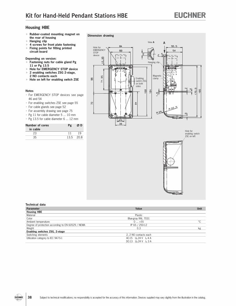
Housing HBE
Technical data
Parameter Value Unit
Housing HBE
Material Plastic
Color Blue-gray RAL 7031
Ambient temperature 0 ... +55 °C
Degree of protection according to EN 60529 / NEMA IP 65 / 250-12
Weight 0.3 kg
Enabling switches ZSG, 2-stage
Switching elements 2, 2 NO contacts each
Utilization category to IEC 947-5-1 AC-15 Ue 24 V Ie 4 A
DC-13 Ue 24 V Ie 3 A
Dimension drawing Rubber-coated mounting magnet onthe rear of housing
Hanging clip 4 screws for front plate fastening Fixing points for fitting printed
circuit board
Depending on version: Fastening nuts for cable gland Pg
11 or Pg 13.5 Hole for EMERGENCY STOP device 2 enabling switches ZSG 2-stage,
2 NO contacts each Hole on left for enabling switch ZSE
Notes
For EMERGENCY STOP devices see page
46 and 54
For enabling switches ZSE see page 55
For cable glands see page 52
For assembly drawing see page 75
Pg 11 for cable diameter 5 ... 10 mm
Pg 13.5 for cable diameter 6 ... 12 mm
Number of cores Pg ∅∅∅∅∅ D
in cable
23 11 19
35 13.5 20.8
∅ D
View A A
Hanging clip
Magneticclamp
Hole forEMERGENCYSTOPdevice
Enablingswitch ZSGon bothsides
Hole forenabling switchZSE on left
39
Kit for Hand-Held Pendant Stations HBE
Subject to technical modifications; no responsibility is accepted for the accuracy of this information. Devices supplied may vary slightly from the illustration in the catalog.
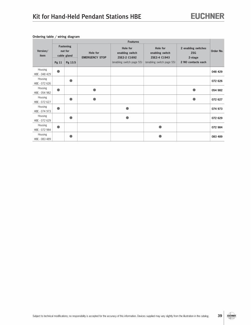
Ordering table / wiring diagram
Features
Order No.
Pg 11 Pg 13.5
Housing 048 429
HBE - 048 429
Housing 072 626
HBE - 072 626
Housing 054 982
HBE - 054 982
Housing 072 627
HBE - 072 627
Housing 074 973
HBE - 074 973
Housing 072 629
HBE - 072 629
Housing 072 984
HBE - 072 984
Housing 083 489
HBE - 083 489
Version/
item
Fastening
nut for
cable glandHole for
EMERGENCY STOP
Hole for
enabling switch
ZSE2-2 C1692
(enabling switch page 55)
Hole for
enabling switch
ZSE2-4 C1943
(enabling switch page 55)
2 enabling switches
ZSG
2-stage
2 NO contacts each

40
Kit for Hand-Held Pendant Stations HBE
Subject to technical modifications; no responsibility is accepted for the accuracy of this information. Devices supplied may vary slightly from the illustration in the catalog.
Dimension drawing
Technical data
Material
Front plate Electrically anodized aluminum, black
Seal NBR, self-adhesive on one side
Ordering table
Item Order No.
HBE front plate, with seal 052 954
HBA front plate, with seal and hole for handwheel HKD 052 955
Front seal for HBE front plate 072 642
Front plate for housing HBE
Front plate
Flat seal
Direction of rotationsymbol lightanodized (fordialswith ∅ 65 mm)
Fastening hole forhandwheel HKD(handwheel HKDsee page 60)

41
Kit for Hand-Held Pendant Stations HBL
Subject to technical modifications; no responsibility is accepted for the accuracy of this information. Devices supplied may vary slightly from the illustration in the catalog.
Kit for hand-held pendant stations HBL
The kit is designed to match individual customer specifications.
The housings differ in the integrated safety element:
Housing without holes and without safety-related components
Housing with dual-channel enabling switch on both sides and hole for
EMERGENCY STOP
Housing with 3-stage enabling switch (1 positively driven contact, 2 NO
contacts) without EMERGENCY STOP
Housing with 3-stage enabling switch (2 positively driven contacts,
2 NO contacts) with hole for EMERGENCY STOP
Various versions of front plate are available:
Front plate for applications with handwheel
Front plate for applications without handwheel
With the related seal, degree of protection IP 65 is achieved.
Customer-specific functionality can be created by using the components
supplied as accessories (pushbuttons, selector switches, key-operated
rotary switches) and/or other components.
For connection to the control system, cables with or without plug
connectors and with different numbers of cores and the relevant flange
sockets are also available as accessories.
42
Kit for Hand-Held Pendant Stations HBL
Subject to technical modifications; no responsibility is accepted for the accuracy of this information. Devices supplied may vary slightly from the illustration in the catalog.
∅D
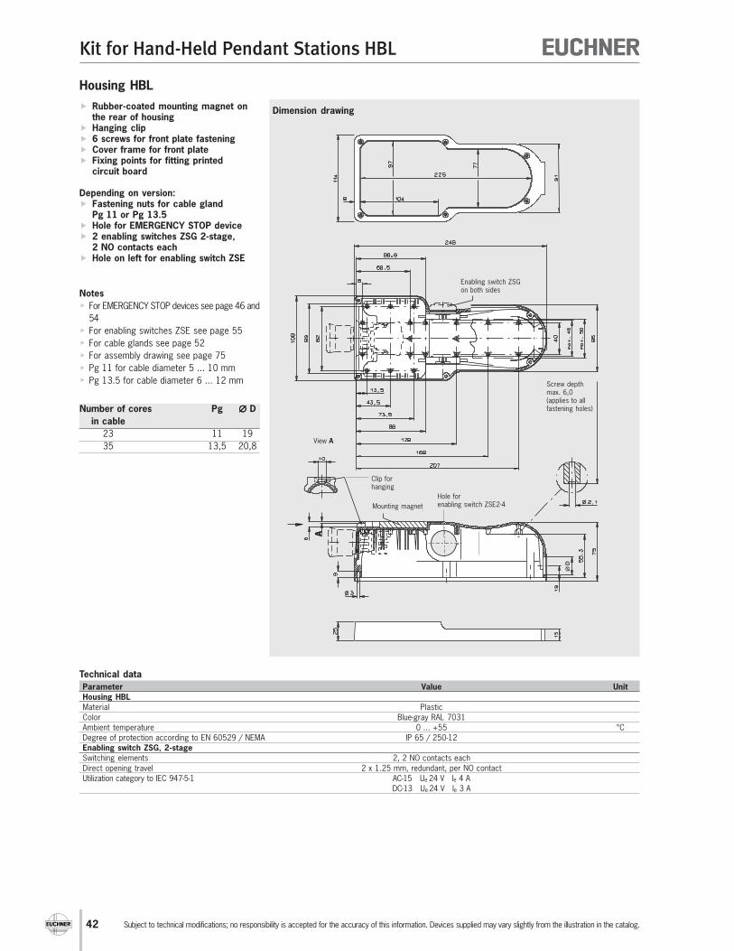
Housing HBL
Technical data
Parameter Value Unit
Housing HBL
Material Plastic
Color Blue-gray RAL 7031
Ambient temperature 0 ... +55 °C
Degree of protection according to EN 60529 / NEMA IP 65 / 250-12
Enabling switch ZSG, 2-stage
Switching elements 2, 2 NO contacts each
Direct opening travel 2 x 1.25 mm, redundant, per NO contact
Utilization category to IEC 947-5-1 AC-15 Ue 24 V Ie 4 A
DC-13 Ue 24 V Ie 3 A
Dimension drawing Rubber-coated mounting magnet onthe rear of housing
Hanging clip 6 screws for front plate fastening Cover frame for front plate Fixing points for fitting printed
circuit board
Depending on version: Fastening nuts for cable gland
Pg 11 or Pg 13.5 Hole for EMERGENCY STOP device 2 enabling switches ZSG 2-stage,
2 NO contacts each Hole on left for enabling switch ZSE
Notes
For EMERGENCY STOP devices see page 46 and
54
For enabling switches ZSE see page 55
For cable glands see page 52
For assembly drawing see page 75
Pg 11 for cable diameter 5 ... 10 mm
Pg 13.5 for cable diameter 6 ... 12 mm
Number of cores Pg ∅∅∅∅∅ D
in cable
23 11 19
35 13,5 20,8
Clip forhanging
View A
A
Mounting magnet
Screw depthmax. 6,0(applies to allfastening holes)
Hole forenabling switch ZSE2-4
Enabling switch ZSGon both sides

43
Kit for Hand-Held Pendant Stations HBL
Subject to technical modifications; no responsibility is accepted for the accuracy of this information. Devices supplied may vary slightly from the illustration in the catalog.
Ordering table / wiring diagram
Features
Version Order No.
Pg 11 Pg 13.5
Housing 073 098
HBL - 073 098
Housing 072 630
HBL - 072 630
Housing 073 113
HBL - 073 113
Housing 072 631
HBL - 072 631
Housing 073 109
HBL - 073 109
Housing 072 632
HBL - 072 632
Housing 072 983
HBL - 072 983
Housing 083 484
HBL - 083 484
1) Blanking plug ∅ 22 supplied for hole for EMERGENCY STOP device
Fastening
nut for
cable gland
Hole for
EMERGENCY STOP
Hole for
enabling switch
ZSE2-2 C1692
(enabling switch page 55)
Hole for
enabling switch
ZSE2-4 C1943
(enabling switch page 55)
2 enabling switches
ZSG
2-stage
2 NO contacts each

44
Kit for Hand-Held Pendant Stations HBL
Subject to technical modifications; no responsibility is accepted for the accuracy of this information. Devices supplied may vary slightly from the illustration in the catalog.
Dimension drawing
Technical data
Material
Front plate Electrically anodized aluminum, black
Seal NBR, self-adhesive on one side
Ordering table
Item Order No.
HBL front plate, with seal 073 138
HBL front plate, with hole for handwheel HKD and seal 073 139
Front seal for HBL front plate 072 641
31
Front plateflat seal
Front platewith hole for
handwheel fastening
Front platewithout hole for
handwheel fastening
Front plate
Flat seal
Fastening holefor handwheel HKD(handwheel HKDsee page 60)
Front plate for housing HBL
45
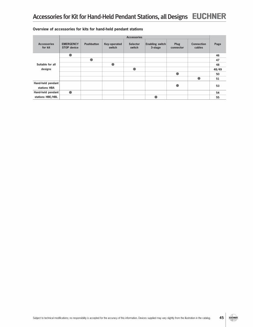
Accessories for Kit for Hand-Held Pendant Stations, all Designs
Subject to technical modifications; no responsibility is accepted for the accuracy of this information. Devices supplied may vary slightly from the illustration in the catalog.
Overview of accessories for kits for hand-held pendant stations
Accessories
46
47
48
48/49
50
51
53
54
55
Accessories
for kit
EMERGENCY
STOP device
Pushbutton Key-operated
switch
Selector
switch
Enabling switch
3-stage
Plug
connector
Connection
cables
Page
Suitable for all
designs
Hand-held pendant
stations HBA
Hand-held pendant
stations HBE/HBL

46
Accessories for Kit for Hand-Held Pendant Stations, all Designs
Subject to technical modifications; no responsibility is accepted for the accuracy of this information. Devices supplied may vary slightly from the illustration in the catalog.
Dimension drawing
Technical data
Parameter Value Unit
Actuating element
Color of actuating button Red
Color of bottom shell Yellow
Switching elements 2, one positively driven contact each
Degree of protection IP 65
Utilization category to IEC 947-5-1 DC-13 Ue 24 V Ie 3 A
Ordering table
Item Order No.
EMERGENCY STOP device (pull release) with 2 switching elements, 1 positively driven contact each 096 298
EMERGENCY STOP device (rotary release) 2 positively driven contacts 096 292
Blanking plug for fastening hole for EMERGENCY STOP device 083 653
EMERGENCY STOP devices according to EN 418
With pull release EMERGENCY STOP device for housing
HBA without handwheel design 2/3and all housings HBA with handwheelbut not including enabling switch ZXE3-stage
Notes
The EMERGENCY STOP device engages when
actuated by pressing, unlocks when pulled,
and is overload-proof
Do not use for housing HBA with 3-stage
enabling switch ZXE
With rotary release EMERGENCY STOP device for
housing HBA
Notes
The EMERGENCY STOP device engages when
actuated by pressing, unlocks when rotated,
and is overload-proof
Dimension drawing
Technical data
Parameter Value Unit
Actuating element
Color of actuating button Red
Color of bottom shell Black
Switching elements 1, 2 positively driven contacts
Degree of protection IP 65
Connection ratings 30 V DC / 3 A
16,2
3
30
15,8
2010,8
0,2 M16 x1
2,8
0,5
12,1
12,3
18
22,1
28,5
Front panelcut-out
Pinassignment
Protectionagainst twisting
Self-adhesive labelColor yellow
49
40 37,5
<Ø
28>
5 12
25
25
2,8
<18>
18
6.
<0,8
>
Ø 16,2 0+0,2
Front panel cut-out
Pin assignment
Socket yellow
Pushbutton red

47
Accessories for Kit for Hand-Held Pendant Stations, all Designs
Subject to technical modifications; no responsibility is accepted for the accuracy of this information. Devices supplied may vary slightly from the illustration in the catalog.
Dimension drawing
Pushbutton
Front panel thicknessmax. 3 mm
Front panelcut-out
Fastening nut Sealing ring
Technical data
Parameter Value Unit
Ambient temperature -25 ... +70 °C
Front degree of protection (integrated in front plate) IP 67
Switching principle Button, snap-action switching element
Switching elements 1 NO contact
Switching current max. 0.1 A
Switching voltage 30 V DC
Connection type Soldered connection
Dimension drawingNotes
Installation in the front plate in the area of the
EMERGENCY STOP switch and the enabling
switch ZSE is not possible on hand-held
pendant stations HBE
Illuminated pushbutton (can be individually labeled)
Technical data
Parameter Value Unit
Ambient temperature -25 ... +55 °C
Front degree of protection (integrated in front plate) IP 65
Switching principle Button, snap-action switching element
Switching elements 1 NC contact, 1 NO contact m
Switching current max. 5 A
Switching voltage max. 250 V AC/DC
Connection type Soldered connection
Ordering table
Item Order No.
Pushbutton, black button 083 640
Pushbutton, red button 086 753
Pushbutton, green button 086 754
Pushbutton, blue button 086 757
Pushbutton, white button 086 755
Illuminated pushbutton, can be individually labeled 074 991
SW
14
5,1
5
6
∅16,8
M12x1
∅13,6
5
12,5 2
∅13,6
0
12,90
∅15
1
1 3
2 4
a
b
-
+
10,5 29 18
15+0,05 0
1,7
0 -0,1
16
+0
,2 0
Ø1
8
max. 6,5
18
Front panel cut-out Wiring diagram
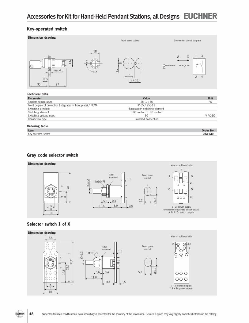
48
Accessories for Kit for Hand-Held Pendant Stations, all Designs
Subject to technical modifications; no responsibility is accepted for the accuracy of this information. Devices supplied may vary slightly from the illustration in the catalog.
Dimension drawing
Technical data
Parameter Value Unit
Ambient temperature -25 ... +55 °C
Front degree of protection (integrated in front plate) / NEMA IP 65 / 250-12
Switching principle Snap-action switching element
Switching element 1 NC contact, 1 NO contact
Switching voltage max. 30 V AC/DC
Connection type Soldered connection
Key-operated switch
Ordering table
Item Order No.
Key-operated switch 083 639
C
Amax.4.5
2735
11.5
14.6
18
Front panel cut-out
15
1.7
min18.
1 3
2 4
CA
Connection circuit diagram
Dimension drawing
Gray code selector switch
View of soldered side
5,2
Ø 6
,2
Ø=
3,2
5,6
10,6 8,9 3,0
0,4
M6x0,75
8
8
5
10
8
20
1,5A
C
B
D
1
2
3
Front panelcut-out
Sealmounted
1 - 3: power supply(connected on printed circuit board)
A, B, C, D: switch outputs
Dimension drawing
Selector switch 1 of X
View of soldered side
8
8
5
Ø=
3,2
5,6
11,0
8,5 3,5
0,4 5,2 Ø 6
,2
M6x0,751,5
10
7,8
14
,6 22
,2 30
,2 2
1
14 13
3
4
Front panelcut-out
Sealmounted
1 - 3: switch outputs13 + 14 power supply

49
Accessories for Kit for Hand-Held Pendant Stations, all Designs
Subject to technical modifications; no responsibility is accepted for the accuracy of this information. Devices supplied may vary slightly from the illustration in the catalog.
Dimension drawing
Rotary knob
16
∅3
,2
∅14,5
3,8 1
∅10
∅7
∅11
∅18,7
3,5
∅17
2,7
Nut cover
Code table, switch with Gray code
OutputD C B A
1 0 0 0 0
2 0 0 0 1
3 0 0 1 1
4 0 0 1 0
5 0 1 1 0
6 0 1 1 1
7 0 1 0 1
8 0 1 0 0
9 1 1 0 0
10 1 1 0 1
11 1 1 1 1
12 1 1 1 0
13 1 0 1 0
14 1 0 1 1
15 1 0 0 1
16 1 0 0 0Connections A - D: switch outputs
Connections 1 - 3: power supply
Circuit diagrams switch 1 of X
1 of 4
1
3
213
14
4
1 of 3
1
3
213
14
1 of 2
2
113
14
Output
1 2
1 1 0
2 0 1
Output1 2 3
1 1 0 0
2 0 1 0
3 0 0 1
Output
1 2 3 4
1 1 0 0 0
2 0 1 0 0
3 0 0 1 0
4 0 0 0 1
Technical data
Parameter Value Unit
Front degree of protection (integrated in front plate) IP 67
Single-hole bushing mounting M6 x 0.75
Detent positions 2, 3, 4, 5, 6, 7, 8, 12 or 16 depending on item
Detent angle Gray code 22.5° / 1 of X: 30°
Output code 1 of 2, 1 of 3, 1 of 4 or Gray code depending on item
Breaking capacity max. 0.4 VA
Switching current max. 0.05 A
Switching voltage max. 25 V AC/DC
Connection type Soldered connection on printed circuit board
Maximum soldering time. ≤ 5 (at t ≤ 260 °C) s
Ordering table
Item Detent angle Order No.
Selector switch, 2 detent positions, 1 of 2, break-before-make 1) 30° 097 026
Selector switch, 3 detent positions, 1 of 3, break-before-make 1) 30° 097 027
Selector switch, 4 detent positions, 1 of 4, break-before-make 1) 30° 097 028
Selector switch, 5 detent positions, Gray code, make-before-break 2) 22.5° 097 029
Selector switch, 6 detent positions, Gray code, make-before-break 2) 22.5° 097 030
Selector switch, 7 detent positions, Gray code, make-before-break 2) 22.5° 097 031
Selector switch, 8 detent positions, Gray code, make-before-break 2) 22.5° 097 032
Selector switch, 12 detent positions, Gray code, make-before-break 2) 22.5° 097 033
Selector switch, 16 detent positions, Gray code, make-before-break 2) 22.5° 097 034
Rotary knob, matt black with a marking, collet fastening for shaft 3.2 mm - 097 141
1) Break-before-make: all outputs are open between the switch positions.
2) Make-before-break: the related outputs are connected between the switch positions.
Detent
position
Detent
positionDetent
position
Detentposition
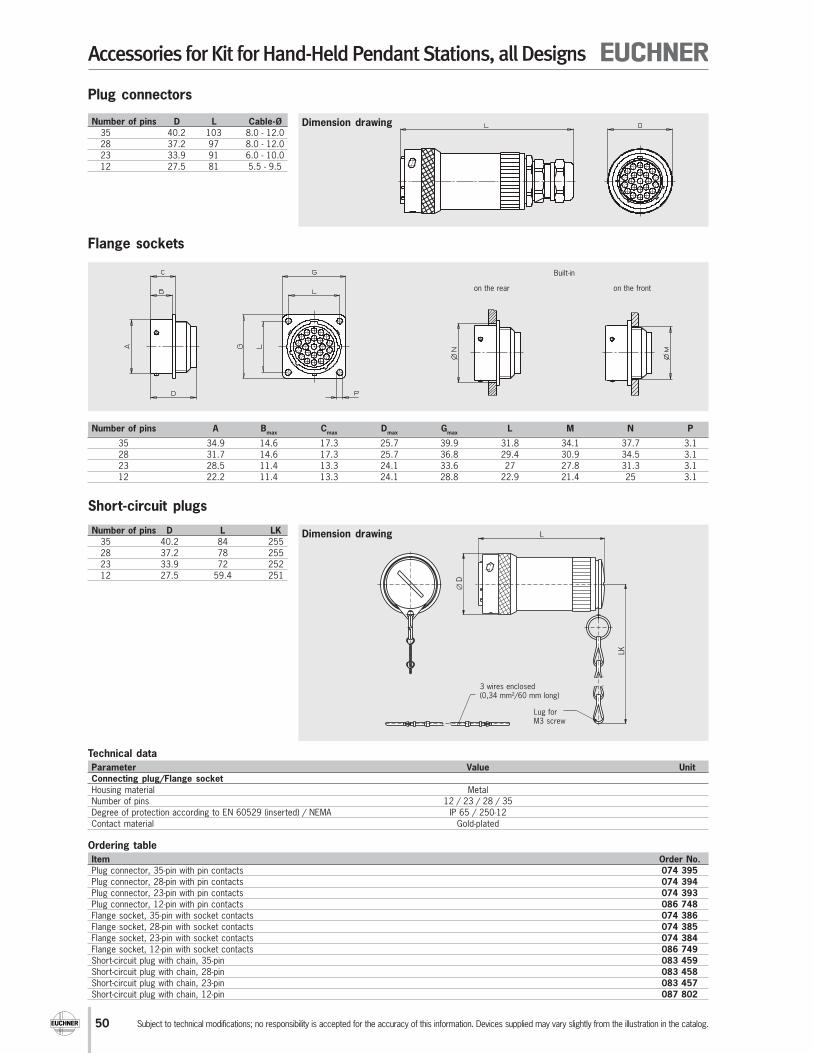
50
Accessories for Kit for Hand-Held Pendant Stations, all Designs
Subject to technical modifications; no responsibility is accepted for the accuracy of this information. Devices supplied may vary slightly from the illustration in the catalog.
Dimension drawing
Technical data
Parameter Value Unit
Connecting plug/Flange socket
Housing material Metal
Number of pins 12 / 23 / 28 / 35
Degree of protection according to EN 60529 (inserted) / NEMA IP 65 / 250-12
Contact material Gold-plated
Ordering table
Item Order No.
Plug connector, 35-pin with pin contacts 074 395
Plug connector, 28-pin with pin contacts 074 394
Plug connector, 23-pin with pin contacts 074 393
Plug connector, 12-pin with pin contacts 086 748
Flange socket, 35-pin with socket contacts 074 386
Flange socket, 28-pin with socket contacts 074 385
Flange socket, 23-pin with socket contacts 074 384
Flange socket, 12-pin with socket contacts 086 749
Short-circuit plug with chain, 35-pin 083 459
Short-circuit plug with chain, 28-pin 083 458
Short-circuit plug with chain, 23-pin 083 457
Short-circuit plug with chain, 12-pin 087 802
Number of pins A Bmax
Cmax
Dmax
Gmax
L M N P
35 34.9 14.6 17.3 25.7 39.9 31.8 34.1 37.7 3.1
28 31.7 14.6 17.3 25.7 36.8 29.4 30.9 34.5 3.1
23 28.5 11.4 13.3 24.1 33.6 27 27.8 31.3 3.1
12 22.2 11.4 13.3 24.1 28.8 22.9 21.4 25 3.1
Number of pins D L Cable-Ø
35 40.2 103 8.0 - 12.0
28 37.2 97 8.0 - 12.0
23 33.9 91 6.0 - 10.0
12 27.5 81 5.5 - 9.5
Built-in
on the rear on the front
Plug connectors
Flange sockets
Dimension drawing
Short-circuit plugs
Number of pins D L LK
35 40.2 84 255
28 37.2 78 255
23 33.9 72 252
12 27.5 59.4 251
L
∅D
LK
Lug forM3 screw
3 wires enclosed(0,34 mm²/60 mm long)
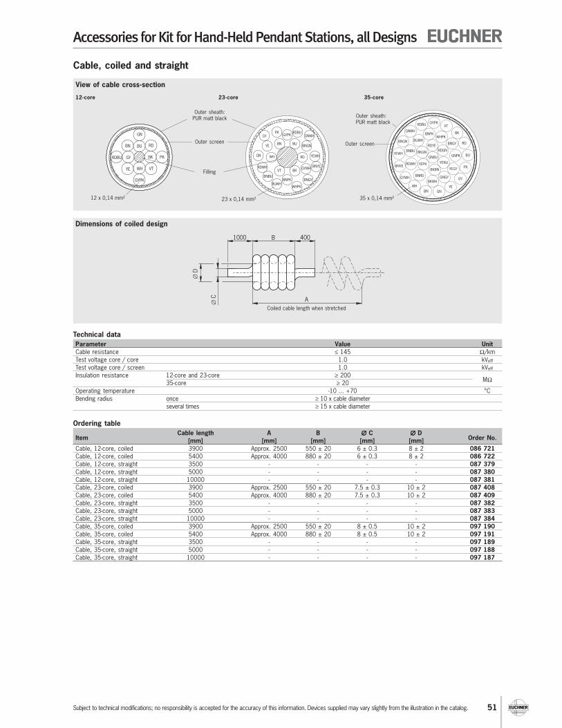
51
Accessories for Kit for Hand-Held Pendant Stations, all Designs
Subject to technical modifications; no responsibility is accepted for the accuracy of this information. Devices supplied may vary slightly from the illustration in the catalog.
Dimensions of coiled design
View of cable cross-section
Cable, coiled and straight
Ordering table
ItemCable length A B ∅∅∅∅∅ C ∅∅∅∅∅ D
Order No.[mm] [mm] [mm] [mm] [mm]
Cable, 12-core, coiled 3900 Approx. 2500 550 ± 20 6 ± 0.3 8 ± 2 086 721
Cable, 12-core, coiled 5400 Approx. 4000 880 ± 20 6 ± 0.3 8 ± 2 086 722
Cable, 12-core, straight 3500 - - - - 087 379
Cable, 12-core, straight 5000 - - - - 087 380
Cable, 12-core, straight 10000 - - - - 087 381
Cable, 23-core, coiled 3900 Approx. 2500 550 ± 20 7.5 ± 0.3 10 ± 2 087 408
Cable, 23-core, coiled 5400 Approx. 4000 880 ± 20 7.5 ± 0.3 10 ± 2 087 409
Cable, 23-core, straight 3500 - - - - 087 382
Cable, 23-core, straight 5000 - - - - 087 383
Cable, 23-core, straight 10000 - - - - 087 384
Cable, 35-core, coiled 3900 Approx. 2500 550 ± 20 8 ± 0.5 10 ± 2 097 190
Cable, 35-core, coiled 5400 Approx. 4000 880 ± 20 8 ± 0.5 10 ± 2 097 191
Cable, 35-core, straight 3500 - - - - 097 189
Cable, 35-core, straight 5000 - - - - 097 188
Cable, 35-core, straight 10000 - - - - 097 187
∅C
B
∅D
A
1000 400
Coiled cable length when stretched
Technical data
Parameter Value Unit
Cable resistance ≤ 145 Ω/km
Test voltage core / core 1.0 kVeff
Test voltage core / screen 1.0 kVeff
Insulation resistance 12-core and 23-core ≥ 200
35-core ≥ 20MΩ
Operating temperature -10 ... +70 °C
Bending radius once ≥ 10 x cable diameter
several times ≥ 15 x cable diameter
GN
RDBU
GYPK
PK
VTYE
BU
BK
WH
GY
BN RD
Outer sheath:PUR matt black
Outer screen
12 x 0,14 mm²
Filling
12-core 23-core 35-core
YEWH
GNWH
WH
GY GYPKPK RDBU
BUBNYE BNGN
RD
BKGYWH
BNGY
GN
RDWHVT
BUWHBNPK
WHPK
BNYE
BNBU
23 x 0,14 mm²
GNWH
BNGN
YEWH
BNYE
GYWH
BNGY
WHPKBUWH
BNBU
RDWH
YE
GY
PK
RDBUGYPK
BNPK
GN
BNRD
BKBN
GNGY
YEGY
BKWH
BKGNGNPK
YEPK
GNBU
YEBU
RDGN
RDYE
BN
BU
WH
RD
VT
BK
Outer sheath:PUR matt black
Outer screen
35 x 0,14 mm²

52
Accessories for Kit for Hand-Held Pendant Stations, all Designs
Subject to technical modifications; no responsibility is accepted for the accuracy of this information. Devices supplied may vary slightly from the illustration in the catalog.
Dimension drawing
M
GL H
SW
Cable gland with anti-kink spiral
Thread M Use Cable diameter SW GL H
M16x1.5 Kit HBA 5 - 10 22 8 71
Pg 11 Kit HBE/HBL 5 - 10 22 11 71
Pg 13.5 Kit HBE/HBL 6 - 12 24 12.5 81
Ordering table
Item Order No.
Cable gland M16x1.5 with anti-kink spiral, color black 083 641
Cable gland Pg 11, with anti-kink spiral and fastening nut, color black 073 982
Cable gland Pg 13.5, with anti-kink spiral and fastening nut, color black 073 983

53
Accessory Kit for Hand-Held Pendant Stations HBA
Subject to technical modifications; no responsibility is accepted for the accuracy of this information. Devices supplied may vary slightly from the illustration in the catalog.
Flange socket 26-pin
+Ø 4,2 0
0,5
13
0
Ø3
0
58,8
SW24SW24
251514
13
12
11
10
87
6
4
3
19
2026
21
23
22
24
16
9
5
2
18
1
17
Connection kitfor design HBA - 098 404 and HBA - 098 405, comprising flange socket 26-pin and short-circuit plug
Technical data
Parameter Value
Flange socket
Housing material Plastic
Number of pins 26
Degree of protection according to EN 60529 (inserted) IP 67
Contact material Copper alloy
Short-circuit plug
Housing material Plastic
Number of pins 26
Degree of protection according to EN 60529 (inserted) IP 67
Contact material Copper alloy
Ordering table
Item Order No.
Flange socket and short-circuit plug 098 412
Short-circuit plug 26-pin for flange socket 26-pin
(Pin 1 bridged with pin 4 and pin 2 with pin 3)
Flange plug, 19-pin with socket contacts
Flange plugfor design HBAS - 072 949 and HBAS - 094 594
Technical data
Parameter Value
Housing material CuZn
Number of pins 19
Degree of protection according to EN 60529 (inserted) IP 65
Contact material Copper alloy
Connection type Soldered connection
Ordering table
Item Order No.
Flange plug, 19-pin with socket contacts 092 374
Front panelcut-out
M23 x
1
1,5
121,3
25
19,8
∅ 2,7
19,8 25
∅ 2
0
19,8
19,8
∅ 2,7
M27 x
1
2
21,3 1
30
23
30
Ø 3,2
23
Front panelcut-out
23
23
∅ 3,2
∅ 2
4+0,
1
Flat seal

54
Accessory Kit for Hand-Held Pendant Stations HBE/HBL
Subject to technical modifications; no responsibility is accepted for the accuracy of this information. Devices supplied may vary slightly from the illustration in the catalog.
Dimension drawing
Technical data
Parameter Value Unit
Color of actuating button Red
Color self-adhesive label Yellow
Switching element 2 NC contacts
Utilization category to IEC 947-5-1 DC-13 Ue 24 V Ie 2.75 A
EMERGENCY STOP device, 22 mm with pull release according to EN 418
Notes
The EMERGENCY STOP device engages when
actuated by pressing, unlocks when pulled,
and is overload-proof
Use only for housing HBE - 054 982 and
HBE - 072 627 (see page 38)Front panel
cut-out
Switching element
Actuating button
Self-adhesive label, yellow
Fastening adapter
Ordering table
Item Order No.
EMERGENCY STOP device, complete with switching elements (2 x NC contacts), 1 pull release 073 985
Blanking plug for fastening hole for EMERGENCY STOP device 059 622

55
Accessory Kit for Hand-Held Pendant Stations HBE/HBL
Subject to technical modifications; no responsibility is accepted for the accuracy of this information. Devices supplied may vary slightly from the illustration in the catalog.
Dimension drawing
Dimension drawing
Technical data
Parameter Value Unit
Housing material Plastic
Fastening hole ∅ 30.5 +0.5 mm
Degree of protection according to IEC 529 IP65 on front
Ambient temperature - 5 ... + 60 °C
Switching principle Slow-action contact element
Utilization category to IEC 947-5-1 AC-15 Ue 24 V Ie 4 A
DC-13 Ue 24 V Ie 3 A
Weight Approx. 0.1 kg
Ordering table
Item Contact elements Switch type Order No.
ZSE2-2 C 1692 2 NO contacts + 1 positively driven contact Single-channel 070 752
ZSE2-4 C 1943 2 NO contacts + 2 positively driven contacts Dual-channel 083 477
Enabling switch ZSE2-2, 3-stage, 1 positively driven contact
Enabling switch ZSE2-4, 3-stage, 2 positively driven contacts
E1
E3
E2
∅40
1..4
30
31
30
∅35
15
60
View without- Sealing cap- Round nut- Front panel
E1
E3
E2
E4
∅40
1..4
30
31
30
∅35
15 77
60
View without- Sealing cap- Round nut- Front panel
Notes
Enabling switch ZSE2-2 C1692 for use in
housing HBE - 074 973 and HBE - 072 629
(see page 38)
Switching elements 210 2 NO contacts + 1 NC contact
Notes
Enabling switch ZSE2-4 C1943 for use in
housing HBE - 072 984 and HBE - 083 489
(see page 38)
Switching elements 220 2 NO contacts + 2 NC contacts
Wiring diagrams/function sequence ZSE 2-2 and ZSE 2-4
Contactopen
closed
closed, enabling
3
43 4
3 4
3
4
1 21
2
E1
E2
E3
ZSE 2-2
3
43 4
3 4
3
4
1 21
2
1 21
2
E1
E2
E3
E4
ZSE 2-4
Not actuatedS
Ö
ZSE2-2 ZSE2-4
E3
E1, E2
E3, E4
E1, E2
SÖ Ö
S1 1
2 2
3
1
2
33
Not actuated
Enabling
Actuatingpoint
Panic function
Restartprotection
Wiring diagram see below
Wiring diagram see below
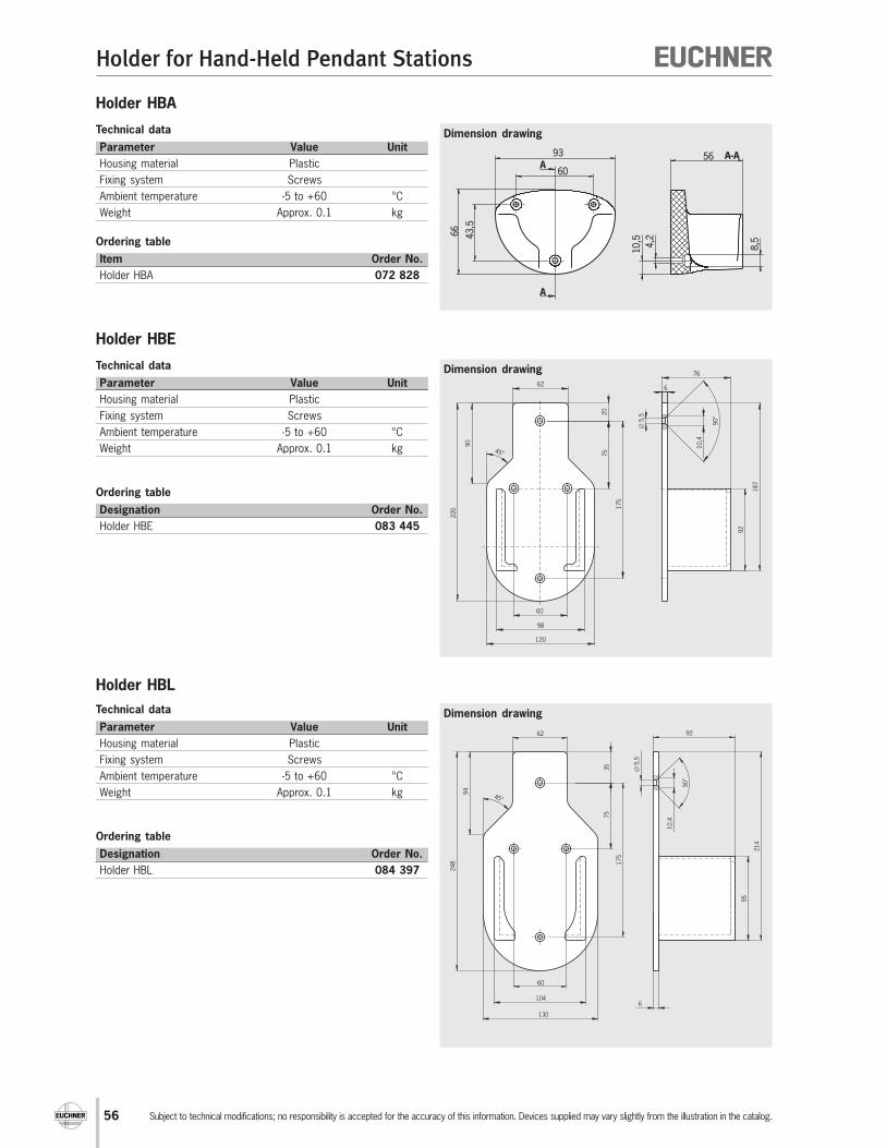
56
Holder for Hand-Held Pendant Stations
Subject to technical modifications; no responsibility is accepted for the accuracy of this information. Devices supplied may vary slightly from the illustration in the catalog.
Dimension drawing
Holder HBA
Technical data
Parameter Value Unit
Housing material Plastic
Fixing system Screws
Ambient temperature -5 to +60 °C
Weight Approx. 0.1 kg
Ordering table
Item Order No.
Holder HBA 072 828
Dimension drawing
60
43,5
66
93
A
A
10,5
4,2
56
8,5
A-A
Dimension drawing
Holder HBE
Technical data
Parameter Value Unit
Housing material Plastic
Fixing system Screws
Ambient temperature -5 to +60 °C
Weight Approx. 0.1 kg
Ordering table
Designation Order No.
Holder HBE 083 445
6020
75
175
45°
62
120
90
98
220
6
∅5,5
10,4
90°
76
187
92
Holder HBL
Technical data
Parameter Value Unit
Housing material Plastic
Fixing system Screws
Ambient temperature -5 to +60 °C
Weight Approx. 0.1 kg
Ordering table
Designation Order No.
Holder HBL 084 397
62
60
94
75
175
248
-
35
45°
104
130
6
∅5,5
10,4
90°
95
214
92

57
Electronic Handwheels
Subject to technical modifications; no responsibility is accepted for the accuracy of this information. Devices supplied may vary slightly from the illustration in the catalog.

58
Electronic Handwheels
Subject to technical modifications; no responsibility is accepted for the accuracy of this information. Devices supplied may vary slightly from the illustration in the catalog.
Function and technology used in handwheels
The change from a handwheel directly coupled to the spindle or axes to
CNC-controlled axes has meant dramatic new developments for the
handwheels. Along with the rotary movement and the visual indication of
the position, the rotation of the handwheel generates square-wave pulses
that are evaluated by the CNC axis controller and initiate the movement
of the axis. With over 20 years of handwheel experience, EUCHNER
provides a wide selection of handwheels that meet the high requirements
on quality, reliability and safe signal generation in the machine tool sector.
The daily use of handwheels places high demands on the mechanical
design. With twin bearings and a wear-free detent, the handwheels are
the optimum choice for trouble-free operation. The detent moment
prevents undesired movement even in the event of machine vibration.
The detent moment and the 100 or 25 pulses per revolution allow
a desired value to be set quickly, reliably and accurately. In addition to
the manual positioning of axes on CNC-controlled machines, handwheels
are also used for medical and telecommunication applications. EUCHNER
also offers handwheels for these applications.
Magnetic detent mechanism
Handwheels with magnetic detent are characterized by their absolutely
wear-free and noiseless detent mechanism.
With 100 detent positions (100 or 25 pulses)
The detent position is generated by a magnetic field. A combination of
100 magnetic north/south poles is generated by the opposing magnetic
fields creating 100 detent positions per revolution of the handwheel.
Thanks to an air gap, the detent mechanism has no wear and is absolutely
maintenance-free. With two ball bearings, the handwheel’s bearing
assembly can withstand high axial and radial forces. Different circuit
outputs are available for all common controllers.
Three different designs are available:
Design HKD
- Suitable for installation in control panels and EUCHNER HBE and
HBL series hand-held pendant stations
- Suitable for integration in universal turning and milling machines
for axis movement
Design HKC
- Suitable for installation in control panels
- The design is particularly suitable for flat operating panels
Design HKA
- Ergonomically shaped dial
- The dial design is the same as on the built-in version in the hand-
held pendant station HBA
- Ideally suited for simultaneous use as a handwheel on the operating
panel and in the hand-held pendant station
Handwheel HKD
Handwheel HKC
Handwheel HKA
Dial
Bearing
FlangeHousing
Printed circuit board
Optics
Code disc
Terminal block
Magnet
Sealing
Magnet
Detent

59
Electronic Handwheels
Subject to technical modifications; no responsibility is accepted for the accuracy of this information. Devices supplied may vary slightly from the illustration in the catalog.
Mechanical detent mechanism
Handwheels with mechanical detent are characterized by their light weight
and shallow mounting depth.
With 100 detent positions (100 or 25 pulses)
A toothed rotor working in conjunction with a roller creates the mechanical
detent position. The roller is pushed between the teeth of the rotor by
a spring and the dial fixed in position. The detent moment is produced
by the movement of the roller over the teeth.
Design HWB
- Suitable for installation in control panels
- With 3-point fastening
Flange
Dial
M4 screw
Knob
O-ring
Seal
Rotor
Slotted disc
A
Optics
Connection terminals
Bearing
Cover
Housing
Spring
Roller
Rotor
Detail A
Mechanical detent mechanism
(magnified)
Housing
There are two different designs available:
Design HWA
- Suitable for installation in control panels.
- Suitable for installation in EUCHNER hand-held pendant stations
- With single-hole bushing mounting
Handwheel HWA
Handwheel HKA
With 20, 25 or 50 detent positions (pulses)
This lower number of pulses per revolution is sufficient for many
applications. Handwheels with a small number of positions can be used
on control devices with a display and indication of the position as a value.
The user obtains the position information via the value displayed.
The position is changed by turning the handwheel. Other uses include
menu-based applications. The handwheel can be used, e.g. to scroll
forwards/backwards or to change or accept default values. Due to the
low number of pulses the handwheels are very small. They are ideal for
portable applications or for integration in control panels on electronic
equipment, e.g. in instruments or in medical and communications
technology.
Three different designs are available:
Design HWD
- Suitable for integration in control panels or stand-alone devices
- For printed circuit board installation
- With 50 pulses per revolution
- Small installation dimensions
- With metal shaft
Design HWE
- Suitable for integration in control panels or stand-alone devices
- For printed circuit board installation
- With 20 pulses per revolution
- Small installation dimensions
- Cost optimized due to use of plastic shaft
Design HWF
- Suitable for integration in control panels or stand-alone devices
- For printed circuit board installation
- With 25 pulses per revolution
- Small installation dimensions
- With pushbutton function as acknowledgement signal
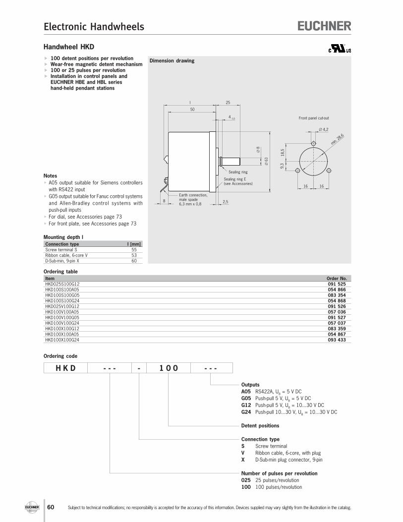
60
Electronic Handwheels
Subject to technical modifications; no responsibility is accepted for the accuracy of this information. Devices supplied may vary slightly from the illustration in the catalog.
Handwheel HKD
Dimension drawing 100 detent positions per revolution Wear-free magnetic detent mechanism 100 or 25 pulses per revolution Installation in control panels and
EUCHNER HBE and HBL serieshand-held pendant stations
Ordering table
Item Order No.
HKD025S100G12 091 525
HKD100S100A05 054 866
HKD100S100G05 083 354
HKD100S100G24 054 868
HKD025V100G12 091 526
HKD100V100A05 057 036
HKD100V100G05 091 527
HKD100V100G24 057 037
HKD100X100G12 083 359
HKD100X100A05 054 867
HKD100X100G24 093 433
H K D - - - - 1 0 0 - - -
Outputs
A05 RS422A, UB = 5 V DC
G05 Push-pull 5 V, UB = 5 V DC
G12 Push-pull 5 V, UB = 10...30 V DC
G24 Push-pull 10...30 V, UB = 10...30 V DC
Detent positions
Connection type
S Screw terminal
V Ribbon cable, 6-core, with plug
X D-Sub-min plug connector, 9-pin
Number of pulses per revolution
025 25 pulses/revolution
100 100 pulses/revolution
Ordering code
l
50
25
∅63
4-0,5
∅8
2,58
18,5
9,3
16 16
∅ 4,2
min. 2
8,6
Sealing ring
Sealing ring E(see Accessories)
Earth connection,male spade6,3 mm x 0,8
Front panel cut-out
Notes
A05 output suitable for Siemens controllers
with RS422 input
G05 output suitable for Fanuc control systems
and Allen-Bradley control systems with
push-pull inputs
For dial, see Accessories page 73
For front plate, see Accessories page 73
Mounting depth l
Connection type l [mm]
Screw terminal S 55
Ribbon cable, 6-core V 53
D-Sub-min, 9-pin X 60
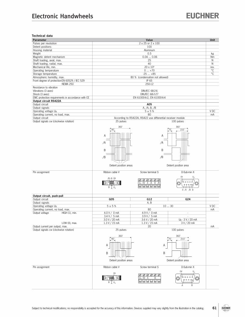
61
Electronic Handwheels
Subject to technical modifications; no responsibility is accepted for the accuracy of this information. Devices supplied may vary slightly from the illustration in the catalog.
Technical data
Parameter Value Unit
Pulses per revolution 2 x 25 or 2 x 100
Detent positions 100
Housing material Aluminum
Weight 0.5 kg
Magnetic detent mechanism 0.04 ... 0.06 Nm
Shaft loading, axial, max. 25 N
Shaft loading, radial, max. 40 N
Mechanical life, min. 20 x 106 rev.
Operating temperature 0 ... +70 °C
Storage temperature -25 ... +85 °C
Atmospheric humidity, max. 80 % (condensation not allowed)
Front degree of protectionEN 60529 / IEC 529 IP 65
NEMA 250 250-12
Resistance to vibration
Vibrations (3 axes) DIN/IEC 68-2-6
Shock (3 axes) DIN/IEC 68-2-27
EMC protection requirements in accordance with CE EN 61000-6-2, EN 61000-6-4
Output circuit RS422A
Output circuit A05
Output signals A, /A, B, /B
Operating voltage UB 5 ± 5 % V DC
Operating current, no load, max. 80 mA
Output circuit According to RS422A, RS422 use differential receiver module
Output signals cw (clockwise rotation) 25 pulses 100 pulses
Detent position areas Detent position area
Pin assignment Ribbon cable V Screw terminal S D-Sub-min X
Output circuit, push-pull
Output circuit G05 G12 G24
Output signals A, B
Operating voltage UB 5 ± 5 % 10 ... 30 V DC
Operating current, no load, max. 80 mA
Output voltage HIGH (1), min. 4.0 V / 0 mA 4.9 V / 0 mA -
3.4 V / 5 mA 3.9 V / 5 mA -
3.0 V / 20 mA 3.6 V / 20 mA UB - 3 V / 20 mA
LOW (0), max. 1.3 V / 15 mA 1.3 V / 15 mA 3 V / 20 mA
Output current per output, max. 20 mA
Output signals cw (clockwise rotation) 25 pulses 100 pulses
Detent position areas Detent position area
Pin assignment Ribbon cable V Screw terminal S D-Sub-min X
U B 0V A /A B /B1
0V
U BAB
/A/B
6
0V
1
U B
A B/A /B
9
90˚
360˚
A
/A
B
/B
75˚
360˚
A
/A
B
/B
210˚
0V
1
U B
A B
9U B 0V A B1
0V
U BAB
6
90˚
360˚
A
B
75˚
360˚
A
B
210˚
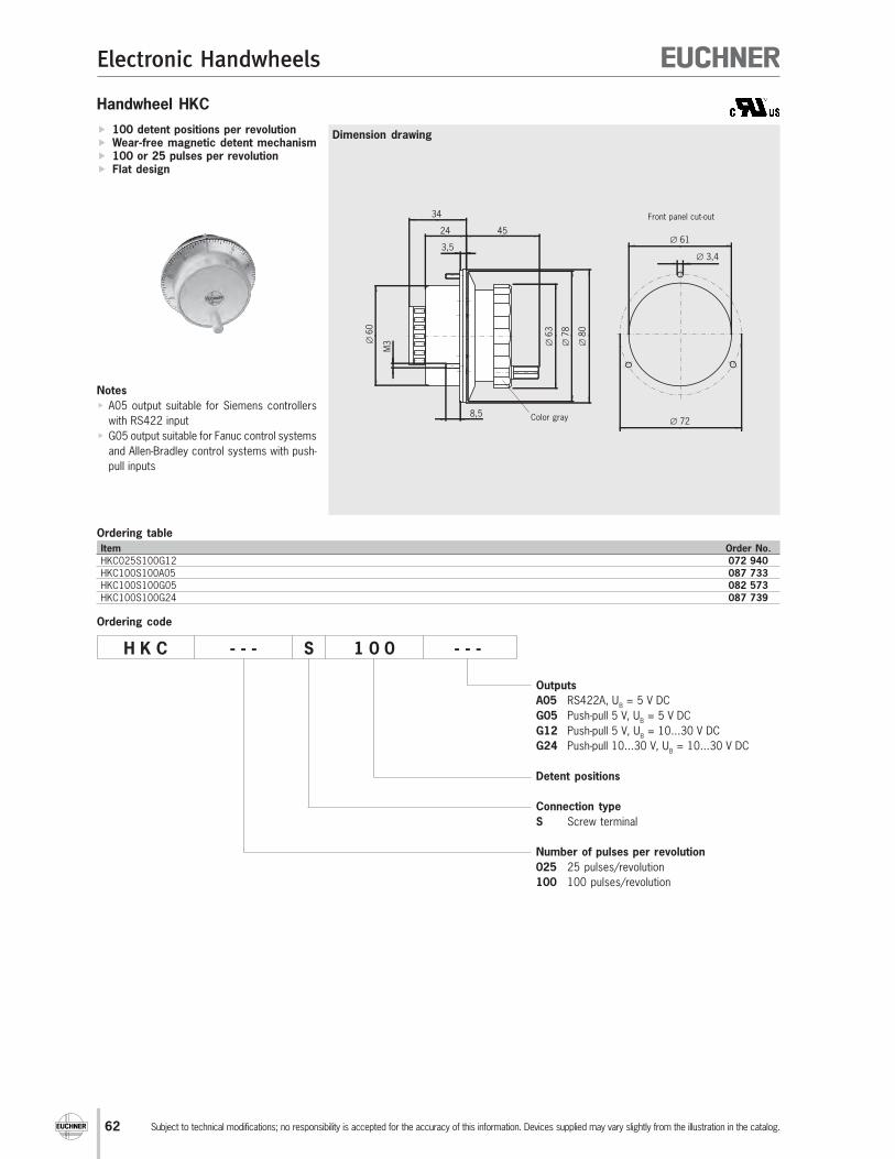
62
Electronic Handwheels
Subject to technical modifications; no responsibility is accepted for the accuracy of this information. Devices supplied may vary slightly from the illustration in the catalog.
Handwheel HKC
Dimension drawing
Ordering table
Item Order No.
HKC025S100G12 072 940
HKC100S100A05 087 733
HKC100S100G05 082 573
HKC100S100G24 087 739
100 detent positions per revolution Wear-free magnetic detent mechanism 100 or 25 pulses per revolution Flat design
H K C - - - S 1 0 0 - - -
Outputs
A05 RS422A, UB = 5 V DC
G05 Push-pull 5 V, UB = 5 V DC
G12 Push-pull 5 V, UB = 10...30 V DC
G24 Push-pull 10...30 V, UB = 10...30 V DC
Detent positions
Connection type
S Screw terminal
Number of pulses per revolution
025 25 pulses/revolution
100 100 pulses/revolution
Ordering code
45
34
24
3,5
∅ 6
3
∅ 7
8
∅ 8
0
∅ 6
0
M3
8,5
∅ 61
∅ 3,4
∅ 72
Front panel cut-out
Color gray
Notes
A05 output suitable for Siemens controllers
with RS422 input
G05 output suitable for Fanuc control systems
and Allen-Bradley control systems with push-
pull inputs

63
Electronic Handwheels
Subject to technical modifications; no responsibility is accepted for the accuracy of this information. Devices supplied may vary slightly from the illustration in the catalog.
U B 0V A B/A /B
Technical data
Parameter Value Unit
Pulses per revolution 2 x 25 or 2 x 100
Detent positions 100
Housing material Thermoplastic
Weight 0.25 kg
Detent Magnetic
Shaft loading, axial, max. 25 N
Shaft loading, radial, max. 40 N
Mechanical life, min. 20 x 106 rev.
Operating temperature 0 ... +50 °C
Storage temperature -20 ... +50 °C
Atmospheric humidity, max. 80 % (condensation not allowed)
Front degree of protectionEN 60529 / IEC 529 IP 65
NEMA 250 250-12
Resistance to vibration
Vibrations (3 axes) DIN/IEC 68-2-6
Shock (3 axes) DIN/IEC 68-2-27
EMC protection requirements in accordance with CE EN 61000-6-2, EN 61000-6-4
Output circuit RS422A
Output circuit A05
Output signals A, /A, B, /B
Operating voltage UB 5 ± 5 % V DC
Operating current, no load, max. 80 mA
Output specifications According to RS422A, RS422 use differential receiver module
Output signals cw (clockwise rotation) 25 pulses 100 pulses
Detent position areas Detent position area
Pin assignment Screw terminal S
Output circuit, push-pull
Output circuit G05 G12 G24
Output signals A, B
Operating voltage UB 5 ± 5 % 10 ... 30 V DC
Operating current, no load, max. 80 mA
Output voltage HIGH (1), min. 4.0 V / 0 mA 4.9 V / 0 mA -
3.4 V / 5 mA 3.9 V / 5 mA -
3.0 V / 20 mA 3.6 V / 20 mA UB - 3 V / 20 mA
LOW (0), max. 1.3 V / 15 mA 1.3 V / 15 mA 3 V / 20 mA
Output current per output, max. 20 mA
Output signals cw (clockwise rotation) 25 pulses 100 pulses
Detent position areas Detent position area
Pin assignment Screw terminal S
U B 0V A B
90˚
360˚
A
/A
B
/B
90˚
360˚
A
/A
B
/B
90˚
360˚
A
B
90˚
360˚
A
B

64
Electronic Handwheels
Subject to technical modifications; no responsibility is accepted for the accuracy of this information. Devices supplied may vary slightly from the illustration in the catalog.
Handwheel HKA
Dimension drawing
Ordering table
Item Order No.
HKA025S100G12 072 956
HKA100S100A05 072 885
HKA100S100G05 072 955
HKA100S100G24 072 967
100 detent positions per revolution Wear-free magnetic detent mechanism 100 or 25 pulses per revolution Haptic handwheel
H K A - - - S 1 0 0 - - -
Outputs
A05 RS422A, UB = 5 V DC
G05 Push-pull 5 V, UB = 5 V DC
G12 Push-pull 5 V, UB = 10...30 V DC
G24 Push-pull 10...30 V, UB = 10...30 V DC
Detent positions
Connection type
S Screw terminal
Number of pulses per revolution
025 25 pulses/revolution
100 100 pulses/revolution
Ordering code
∅ 61
∅ 3,4
∅ 72
Front panel cut-out9
6,5
M3
R 4
1
30 28
40
45
∅ 6
0
Color black
Notes
A05 output suitable for Siemens controllers
with RS422 input
G05 output suitable for Fanuc control systems
and Allen-Bradley control systems with
push-pull inputs
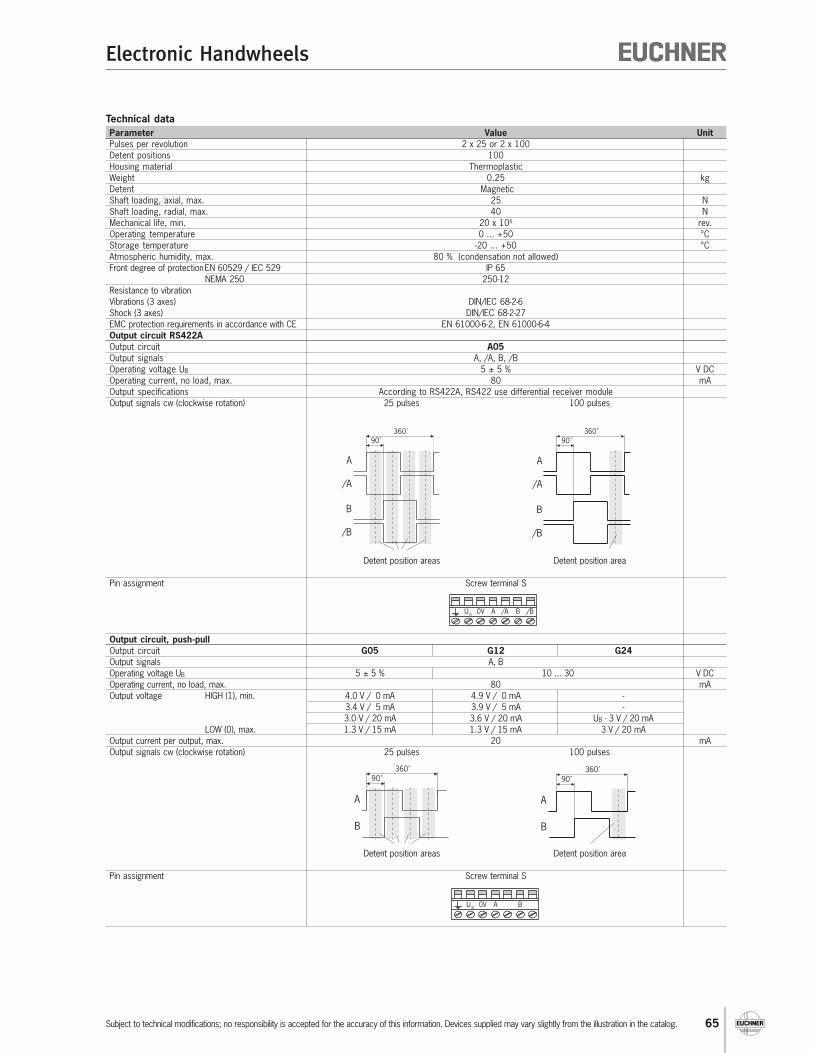
65
Electronic Handwheels
Subject to technical modifications; no responsibility is accepted for the accuracy of this information. Devices supplied may vary slightly from the illustration in the catalog.
U B 0V A B/A /B
Technical data
Parameter Value Unit
Pulses per revolution 2 x 25 or 2 x 100
Detent positions 100
Housing material Thermoplastic
Weight 0.25 kg
Detent Magnetic
Shaft loading, axial, max. 25 N
Shaft loading, radial, max. 40 N
Mechanical life, min. 20 x 106 rev.
Operating temperature 0 ... +50 °C
Storage temperature -20 ... +50 °C
Atmospheric humidity, max. 80 % (condensation not allowed)
Front degree of protectionEN 60529 / IEC 529 IP 65
NEMA 250 250-12
Resistance to vibration
Vibrations (3 axes) DIN/IEC 68-2-6
Shock (3 axes) DIN/IEC 68-2-27
EMC protection requirements in accordance with CE EN 61000-6-2, EN 61000-6-4
Output circuit RS422A
Output circuit A05
Output signals A, /A, B, /B
Operating voltage UB 5 ± 5 % V DC
Operating current, no load, max. 80 mA
Output specifications According to RS422A, RS422 use differential receiver module
Output signals cw (clockwise rotation) 25 pulses 100 pulses
Detent position areas Detent position area
Pin assignment Screw terminal S
Output circuit, push-pull
Output circuit G05 G12 G24
Output signals A, B
Operating voltage UB 5 ± 5 % 10 ... 30 V DC
Operating current, no load, max. 80 mA
Output voltage HIGH (1), min. 4.0 V / 0 mA 4.9 V / 0 mA -
3.4 V / 5 mA 3.9 V / 5 mA -
3.0 V / 20 mA 3.6 V / 20 mA UB - 3 V / 20 mA
LOW (0), max. 1.3 V / 15 mA 1.3 V / 15 mA 3 V / 20 mA
Output current per output, max. 20 mA
Output signals cw (clockwise rotation) 25 pulses 100 pulses
Detent position areas Detent position area
Pin assignment Screw terminal S
U B 0V A B
90˚
360˚
A
/A
B
/B
90˚
360˚
A
/A
B
/B
90˚
360˚
A
B
90˚
360˚
A
B

66
Electronic Handwheels
Subject to technical modifications; no responsibility is accepted for the accuracy of this information. Devices supplied may vary slightly from the illustration in the catalog.
Handwheel HWA
Dimension drawing
Ordering table
Item Packaging unit Order No.
HWA025T100G12/V10 10 pcs. 072 972
HWA100T100A05/V10 10 pcs. 072 970
HWA100T100G05/V10 10 pcs. 072 971
100 detent positions per revolution Mechanical detent mechanism 100 or 25 pulses per revolution Single-hole bushing mounting
Front panel cut-out
H W A - - - T 1 0 0 - - -
Outputs
A05 RS422A, UB = 5 V DC
G05 Push-pull 5 V, UB = 5 V DC
G12 Push-pull 5 V, UB = 12 V DC
Detent positions
Connection type
T Screw terminal
Number of pulses per revolution
025 25 pulses/revolution
100 100 pulses/revolution
Ordering code
3,3 /1.7 tief
9,2
19
Color black
51
60
30
25
,5
1521,826
16,5
48
66 ±1
Disk with adhesive film
Fastening screw
Notes
A05 output suitable for Siemens controllers
with RS422 input
G05 output suitable for Fanuc control systems
and Allen-Bradley control systems with
push-pull inputs

67
Electronic Handwheels
Subject to technical modifications; no responsibility is accepted for the accuracy of this information. Devices supplied may vary slightly from the illustration in the catalog.
Technical data
Parameter Value Unit
Pulses per revolution 2 x 25 or 2 x 100
Detent positions 100
Housing material Plastic/metal
Weight 0.1 kg
Detent Mechanical
Shaft loading, axial, max. 25 N
Shaft loading, radial, max. 40 N
Mechanical life, min. 1 x 10⁶ rev.
Operating temperature 0 ... +50 °C
Storage temperature -20 ... +50 °C
Atmospheric humidity, max. 80 % (condensation not allowed)
Front degree of protectionEN 60529 / IEC 529 IP65
NEMA 250 250-12
Output circuit RS422A
Output circuit A05
Output signals A, /A, B, /B
Operating voltage UB 5 ± 10 % V DC
Operating current, no load, max. 80 mA
Output specifications According to RS422A, RS422 use differential receiver module
Output signals cw (clockwise rotation) 100 pulses
Detent position area
Pin assignment Screw terminal T
Output circuit, push-pull
Output circuit G05 G12
Output signals A, B
Operating voltage UB 5 ± 10 % 12 ± 10 % V DC
Operating current, no load, max. 80 mA
Output voltage HIGH (1), min. 4.0 V / 20 mA
LOW (0), max. 0.5 V / 20 mA
Output current per output, max. 20 mA
Output signals CW (clockwise rotation) 100 pulses 25 pulses
Detent position area Detent position areas
Pin assignment Screw terminal T
90˚
360˚
A
/A
B
/B
+5V 0V A A B B
+UB 0V A B
90˚
360˚
A
B
90˚
360˚
A
B
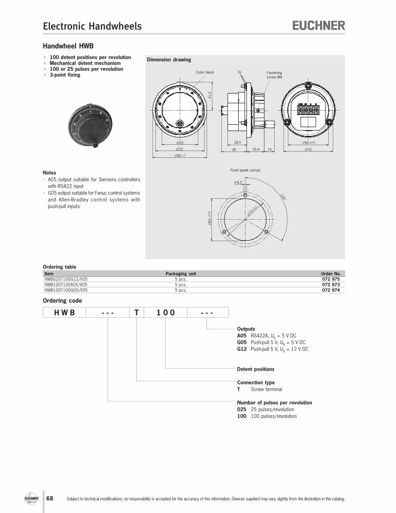
68
Electronic Handwheels
Subject to technical modifications; no responsibility is accepted for the accuracy of this information. Devices supplied may vary slightly from the illustration in the catalog.
Handwheel HWB
Dimension drawing
Ordering table
Item Packaging unit Order No.
HWB025T100G12/V05 5 pcs. 072 975
HWB100T100A05/V05 5 pcs. 072 973
HWB100T100G05/V05 5 pcs. 072 974
100 detent positions per revolution Mechanical detent mechanism 100 or 25 pulses per revolution 3-point fixing
∅4,5
∅6
2±
0,5
120°
∅72
±0,1
∅60±0,5
∅721525,438
28,5
3x
∅53
∅72
∅80 ±1
41,5
Front panel cut-out
Color black
H W B - - - T 1 0 0 - - -
Outputs
A05 RS422A, UB = 5 V DC
G05 Push-pull 5 V, UB = 5 V DC
G12 Push-pull 5 V, UB = 12 V DC
Detent positions
Connection type
T Screw terminal
Number of pulses per revolution
025 25 pulses/revolution
100 100 pulses/revolution
Ordering code
Notes
A05 output suitable for Siemens controllers
with RS422 input
G05 output suitable for Fanuc control systems
and Allen-Bradley control systems with
push-pull inputs
Fasteningscrew M4
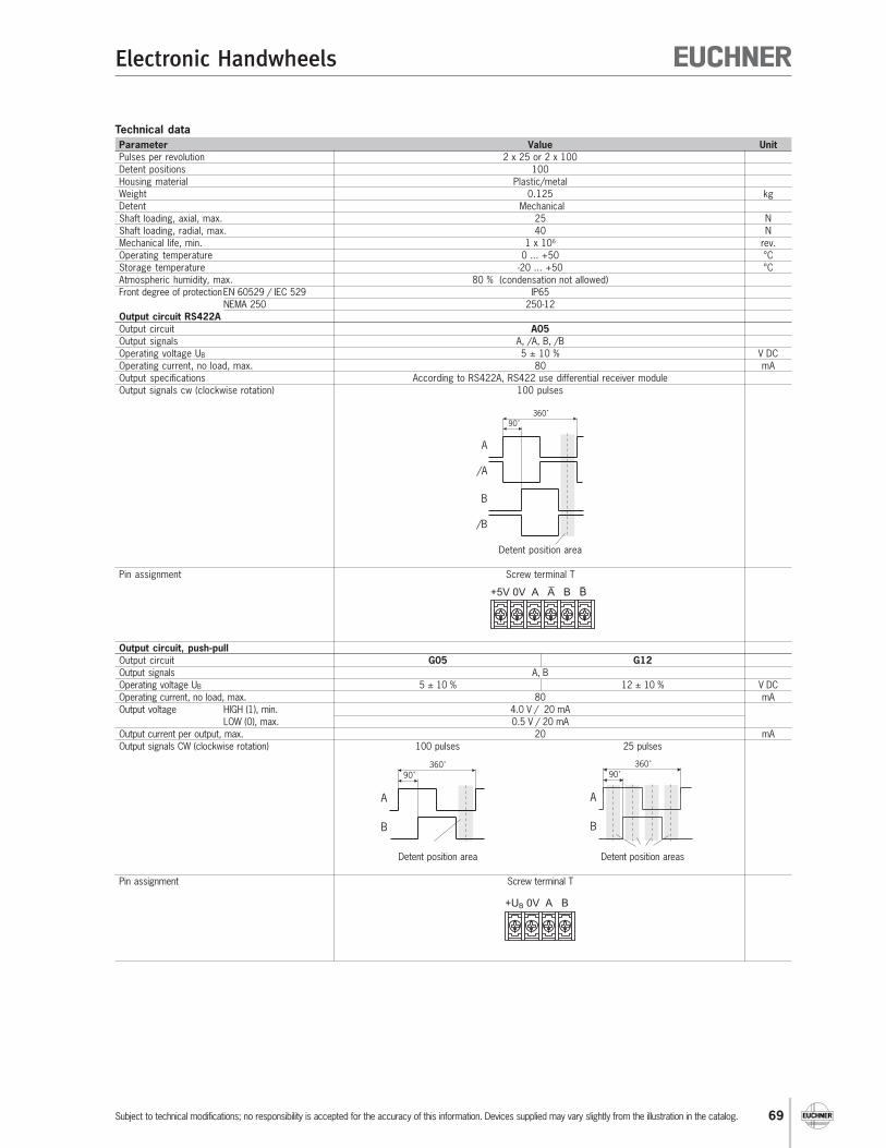
69
Electronic Handwheels
Subject to technical modifications; no responsibility is accepted for the accuracy of this information. Devices supplied may vary slightly from the illustration in the catalog.
Technical data
Parameter Value Unit
Pulses per revolution 2 x 25 or 2 x 100
Detent positions 100
Housing material Plastic/metal
Weight 0.125 kg
Detent Mechanical
Shaft loading, axial, max. 25 N
Shaft loading, radial, max. 40 N
Mechanical life, min. 1 x 10⁶ rev.
Operating temperature 0 ... +50 °C
Storage temperature -20 ... +50 °C
Atmospheric humidity, max. 80 % (condensation not allowed)
Front degree of protectionEN 60529 / IEC 529 IP65
NEMA 250 250-12
Output circuit RS422A
Output circuit A05
Output signals A, /A, B, /B
Operating voltage UB 5 ± 10 % V DC
Operating current, no load, max. 80 mA
Output specifications According to RS422A, RS422 use differential receiver module
Output signals cw (clockwise rotation) 100 pulses
Detent position area
Pin assignment Screw terminal T
Output circuit, push-pull
Output circuit G05 G12
Output signals A, B
Operating voltage UB 5 ± 10 % 12 ± 10 % V DC
Operating current, no load, max. 80 mA
Output voltage HIGH (1), min. 4.0 V / 20 mA
LOW (0), max. 0.5 V / 20 mA
Output current per output, max. 20 mA
Output signals CW (clockwise rotation) 100 pulses 25 pulses
Detent position area Detent position areas
Pin assignment Screw terminal T
90˚
360˚
A
/A
B
/B
+5V 0V A A B B
+UB 0V A B
90˚
360˚
A
B
90˚
360˚
A
B
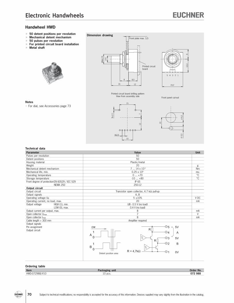
70
Electronic Handwheels
Subject to technical modifications; no responsibility is accepted for the accuracy of this information. Devices supplied may vary slightly from the illustration in the catalog.
Handwheel HWD
Dimension drawing
Ordering table
Item Packaging unit Order No.
HWD-072988/V10 10 pcs. 072 988
50 detent positions per revolution Mechanical detent mechanism 50 pulses per revolution For printed circuit board installation Metal shaft
Technical data
Parameter Value Unit
Pulses per revolution 50
Detent positions 50
Housing material Plastic/metal
Weight 20 g
Mechanical detent mechanism 7 ... 14 x 10-3 Nm
Mechanical life, min. 0.25 x 10⁶ rev.
Operating temperature 0 ... +70 °C
Storage temperature -10 ... +80 °C
Front degree of protectionEN 60529 / IEC 529 IP 65
NEMA 250 250-12
Output circuit
Output circuit Transistor open collector, 4.7 kΩ pull-up
Output signals A, B
Operating voltage UB 5 ±10% V DC
Operating current, no load, max. 20 mA
Output voltage HIGH (1), min. UB - 0.5 V (no load)
LOW (0), max. 0.4 V (no load)
Output current per output, max. 8 mA
Open collector Umax 7 V
Open collector Imax 8 mA
Cable length > 300 mm Amplifier required
Output signals
Pin assignment
Output circuit
912,3
∅9,2
∅3,2
10
19,2
5 4 3 2 1
9x
1∅
15
712
4x2,5
10
8 8,5
1216
∅6
M9x0
,75
Front panel cut-out
Printed circuit board drilling patternView from assembly side
Front plate max. 3,5
Printed circuitboard
A
5V
B
0VR = 4,7kΩ
4
5
3
2
1
5V
R
R
Notes
For dial, see Accessories page 73
Detent position area
cw
1
0
1
0
A
B

71
Electronic Handwheels
Subject to technical modifications; no responsibility is accepted for the accuracy of this information. Devices supplied may vary slightly from the illustration in the catalog.
Handwheel HWE
Dimension drawing
Ordering table
Item Packaging unit Order No.
HWE-072989/V10 10 pcs. 072 989
20 detent positions per revolution Mechanical detent mechanism 20 pulses per revolution For printed circuit board installation Plastic shaft
Technical data
Parameter Value Unit
Pulses per revolution 20
Detent positions 20
Housing material Plastic/metal
Weight 15 g
Mechanical detent mechanism 3 ... 10 x 10-3 Nm
Mechanical life, min. 1 x 10⁶ rev.
Operating temperature 0 ... +60 °C
Storage temperature -10 ... +80 °C
Front degree of protectionEN 60529 / IEC 529 IP 65
NEMA 250 250-12
Output circuit
Output circuit CMOS level
Output signals A, B
Operating voltage UB 5 ±10% V DC
Operating current, no load, max. 40 mA
Output voltage HIGH (1), min. UB - 0.5 V (no load)
LOW (0), max. 0.5 V (no load)
Cable length > 300 mm Amplifier required
Output signals
Pin assignment
Output circuit
Detent position area
cw
1
0
1
0
A
B
B
5V
A
0V
3
4
2
1
74HC14
12,3
9,5
24,5
10
∅9,2
∅3,2
12
19,2
4 3 2 1
2,5x3
8x∅
1
7
12
13
15
7,5
16
8 8,5
12
∅6
M9x0
,75
Front panel cut-out
Printed circuit board drilling patternView from assembly side
Front plate max. 3,5
Printed circuitboard
Notes
For dial, see Accessories page 73

72
Electronic Handwheels
Subject to technical modifications; no responsibility is accepted for the accuracy of this information. Devices supplied may vary slightly from the illustration in the catalog.
Handwheel HWF
Dimension drawing 25 detent positions per revolution Mechanical detent mechanism 25 pulses per revolution For printed circuit board installation Pushbutton function
Technical data
Parameter Value Unit
Pulses per revolution 25
Detent positions 25
Housing material Plastic/metal
Weight 20 g
Mechanical detent mechanism 3 ... 7 x 10⁻³ Nm
Mechanical life, min. 1 x 10⁶ rev.
Mechanical life pushbutton, min. 500 x 103 actuations
Pushbutton stroke 1.2 mm
Operating temperature 0 ... +60 °C
Storage temperature -10 ... +80 °C
Front degree of protectionEN 60529 / IEC 529 IP 65
NEMA 250 250-12
Resistance to vibration
Vibrations (3 axes) DIN/IEC 68-2-6
Shock (3 axes) DIN/IEC 68-2-27
Output circuit
Output circuit Transistor open collector, 10 kΩ pull-up
Output signals A, B
Operating voltage UB 5 ±10% V DC
Operating current, no load, max. 10 mA
Output voltage HIGH (1), min. UB - 0.5 V (no load)
LOW (0), max. 0.4 V (no load)
Cable length > 300 mm Amplifier required
Pushbutton Umax 12 V DC
Pushbutton Imax (resistive load) 20 mA
Output signals
Pin assignment
Output circuit
Soldering
Manual soldering Max. 350 °C / max. 3 s
Reflow soldering Not possible
A
5V
B
S
0VR = 10 kΩ
2
1
3
4
5
R
R
cw
1
0
1
0
A
B
Detent position area
Ordering table
Item Packaging unit Order No.
HWF-072990/V10 10 pcs. 072 990
9,5
11,7
25,5
15
19,2
5 4 3 2 1
9x
1∅
4x2,5
6
11
14
∅ 9,2
18,6
10
∅6
M9x0
,75
8
16 11
Printed circuit board drilling patternView from assembly side
Printed circuit board
Notes
For dial, see Accessories page 69

73
Electronic Handwheels
Subject to technical modifications; no responsibility is accepted for the accuracy of this information. Devices supplied may vary slightly from the illustration in the catalog.
Dimension drawing
Accessories
Dials for handwheels HWD/HWE/HWF
Material plastic, color gray (similar RAL 7032)
Dimensions
Design d e
Dial GD 60 7.5 10
Dial GE 60 12.5 15
Ordering table
Item Packaging unit Order No.
Dial GD60/V10 10 pcs. 072 991
Dial GE60/V10 10 pcs. 072 992
Dials for handwheel HKD
Dimensions
Design ∅ ∅ ∅ ∅ ∅ a ∅∅∅∅∅ b c
Dial 90 mm 90 63 41
Dial 78 mm 78 63 39
Dial 65 mm 65 44 42
Dial 58 mm 58 44 40
Ordering table
Item Order No.
Dial 90 mm black 057 266
Dial 90 mm silver 057 268
Dial 78 mm black 057 280
Dial 78 mm silver 057 272
Dial 65 mm black 057 318
Dial 65 mm silver 057 314
Dial 58 mm black 059 276
Front plate for handwheel HKD
Front plate with bonded seal
Seal handwheels without front plate using sealing ring E
Dimensions
Design e f g h k m n p s r
F 110 110 90 90 - - DIN74-Am5 - - R48
G 108 108 89 89 - - 5.2 - - R48
H 114.3 127 101.6 89 - - 5.2 12.7 49.5 R48
Ordering table
Item Order No.
Sealing ring E 054 861
Front plate F with seal 028 760
Front plate G with seal 028 761
Front plate H with seal 028 762
e
n
r
f
sp
g
h
Dimension drawing
c
b aDimension drawing
∅40
e
d
∅6
Front plate F, G, H

74
Appendix
Subject to technical modifications; no responsibility is accepted for the accuracy of this information. Devices supplied may vary slightly from the illustration in the catalog.
Dimension drawing
Dimension drawing
Dimension drawing hand-held pendant stations HBA
Top shell HBA with handwheel
Top shell HBA without handwheel
∅12,5
1 x
45˚
2
∅5,5
5,5
∅8
7,5
46,5
56,5
33
52
30
89,5
92,5
50
∅ 60
Point for fixing circuit board(circuit board 1,5 mm thick,screw 2,5 x 8)
46,5
∅8
R 32
,5
55
25
125
50
52
93
92,5
28
38
∅8
∅5,5
5,5
∅12,5
2
1 x
45˚
Point for fixing circuit board(circuit board 1,5 mm thick,screw 2,5 x 8)
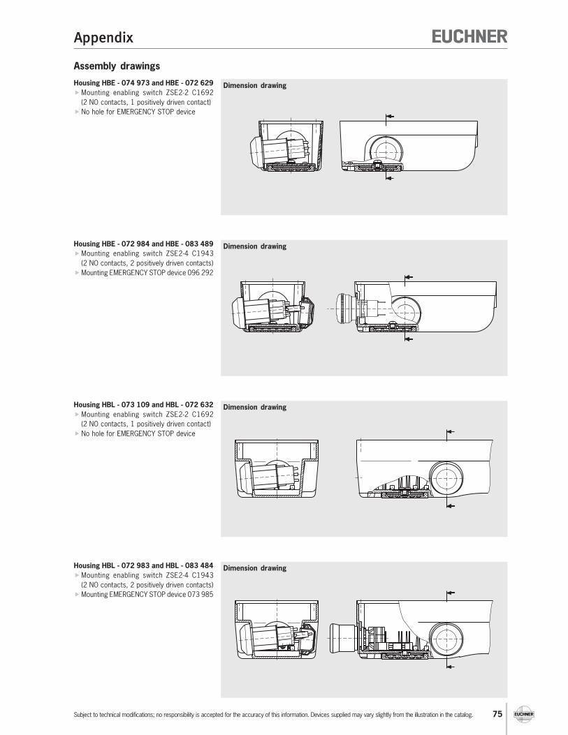
75
Appendix
Subject to technical modifications; no responsibility is accepted for the accuracy of this information. Devices supplied may vary slightly from the illustration in the catalog.
Assembly drawings
Dimension drawingHousing HBE - 074 973 and HBE - 072 629
Mounting enabling switch ZSE2-2 C1692
(2 NO contacts, 1 positively driven contact)
No hole for EMERGENCY STOP device
Dimension drawingHousing HBE - 072 984 and HBE - 083 489
Mounting enabling switch ZSE2-4 C1943
(2 NO contacts, 2 positively driven contacts)
Mounting EMERGENCY STOP device 096 292
Dimension drawingHousing HBL - 073 109 and HBL - 072 632
Mounting enabling switch ZSE2-2 C1692
(2 NO contacts, 1 positively driven contact)
No hole for EMERGENCY STOP device
Dimension drawingHousing HBL - 072 983 and HBL - 083 484
Mounting enabling switch ZSE2-4 C1943
(2 NO contacts, 2 positively driven contacts)
Mounting EMERGENCY STOP device 073 985
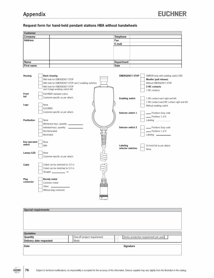
76
Appendix
Subject to technical modifications; no responsibility is accepted for the accuracy of this information. Devices supplied may vary slightly from the illustration in the catalog.
Request form for hand-held pendant stations HBA without handwheels
Customer
Company
Address
Name
First name
Telephone
Fax
Department
Date
Date
Quotation
Delivery date requested
One-off project requirement
Week
Series production requirement per yearQuantity
Signature
Special requirements
Housing Basic housing
With hole for EMERGENCY STOP
With hole for EMERGENCY STOP and 2 enabling switches
With hole for EMERGENCY STOP and 3-stage enabling switch left
Logo None
EUCHNER
Customer-specific as per attach.
Front foil
EUCHNER standard colors
Customer-specific as per attach.
Pushbutton None
Membrane keys, quantity:
Individual keys, quantity:
Not illuminated
Illuminated
Key-operatedswitch
None
With
Lamps/LED None
Customer-specific as per attach.
Cable Coiled can be stretched to 3.5 m
Coiled can be stretched to 5.0 m
Straight: m
Enabling switch 1 NO contact each right and left
1 NO contact each/NC contact right and left
Without enabling switch
Labelingselector switches
On front foil as per attach.
None
EMERGENCY STOP OMRON (only with enabling switch ZXE)
Moeller (pull release)
Without EMERGENCY STOP
2 NC contacts
1 NC contacts
Selector switch 1 Positions Gray code
Labeling
Positions 1 of X
Selector switch 2 Positions Gray code
Labeling
Positions 1 of X
Plug connector
Burndy metal
Coninvers metal
Without plug connector
Other:

77
Appendix
Subject to technical modifications; no responsibility is accepted for the accuracy of this information. Devices supplied may vary slightly from the illustration in the catalog.
Request form for hand-held pendant stations HBA with handwheels
Customer
Company
Address
Name
First name
Telephone
Fax
Department
Date
Date
Quotation
Delivery date requested
One-off project requirement
Week
Series production requirement per yearQuantity
Signature
Special requirements
Logo EUCHNER standard
Customer-specific as per attach.
EMERGENCY STOP OMRON (only with enabling switch ZXE)
Moeller (pull release)
Without EMERGENCY STOP
2 NC contacts
1 NC contact
Selector switch left
Positions Gray code
Without selector switchLabeling
Positions 1 of X
Selector switchright
Positions Gray code
Without selector switchLabeling
Positions 1 of X
LED Without LED
Green
Other color:
Front foil EUCHNER standard
Background color:
Pushbuttons 3 membrane buttons 1)
Other: 1)
Without buttons
Without LEDs
With LEDs
1) Labeling of the buttons as per attachment
Plug connector Burndy metal
Coninvers metal
Without plug connector
Other:
Enabling switch Enabling switch ZXE left
1 NO contact each right and left
1 NO contact each/NC contact right and left
Without enabling switch
Handwheel Operating voltage Ub = DC 5 V
Operating voltage Ub = DC 10 - 30 V
RS422 output
Output push-pull 5 V
Output push-pull +Ub
100 pulses
25 pulses 2)
2) Only for Mitsubishi control system
On which control system willthe handwheelbe operated?
Siemens
Fanuc
Mitsubishi
Allen Bradley
Cable Coiled can be stretched to 3.5 m
Coiled can be stretched to 5.0 m
Straight: m

78
Appendix
Subject to technical modifications; no responsibility is accepted for the accuracy of this information. Devices supplied may vary slightly from the illustration in the catalog.
Hand-held pendant stations HBE request form
Customer
Company
Address
Name
First name
Telephone
Fax
Department
Date
Date
Quotation
Delivery date requested
One-off project requirement
Week
Series production requirement per yearQuantity
Signature
Special requirements
Logo None
Customer-specific as per attach.
EMERGENCY STOP
Moeller (pull release, EN418)
Without EMERGENCY STOP
2 NC contacts
1 NC contact
Key-operatedswitch
None
With
Plug connector Burndy metal
Coninvers metal
Without plug connector
Other:
Handwheel Operating voltage Ub = DC 5 V
Operating voltage Ub = DC 10 - 30 V
RS422 output
Output push-pull 5 V
Output push-pull +Ub
100 pulses
25 pulses 2)
2) Only for Mitsubishi control system
On which control system willthe handwheelbe operated?
Siemens
Fanuc
Mitsubishi
Allen Bradley
Labelingselector switches
Through scale wheels
On front plate
Front plate EUCHNER Standardblack anodizedsilver labeling
9 keys with membrane
Customer-specific as per attach.
Pushbutton None
Number of NO contacts
Number of NC contacts
Not illuminated
Symbol plate labeling as per attach.
Illuminated
Front plate labeling as per attach.
Lamp/LED None
Customer-specific as per attach.
Potentiometer None
Technical data:
Cable Coiled can be stretched from 1.5 to 3.5
Coiled can be stretched from 2.0 to 5.0
Straight: m
Enabling switch ZSG, 2 NC contacts each, on both sides
ZSE 2-4, 2 NO contacts + 2 positively driven contact, left
ZSE 2-2, 2 NO contacts + 1 positively driven contact, left
Without enabling switch
Selector switch right
Labeling
Positions 1 of X
Positions Gray code
Without selector switch right
Dial EUCHNER logo
Customer-specific logo as per attach.
Silver 65 mm
Black 65 mm
Silver 78 mm
Black 78 mm
Selector switch left
Positions Gray code
Without selector switch left
Labeling
Positions 1 of X
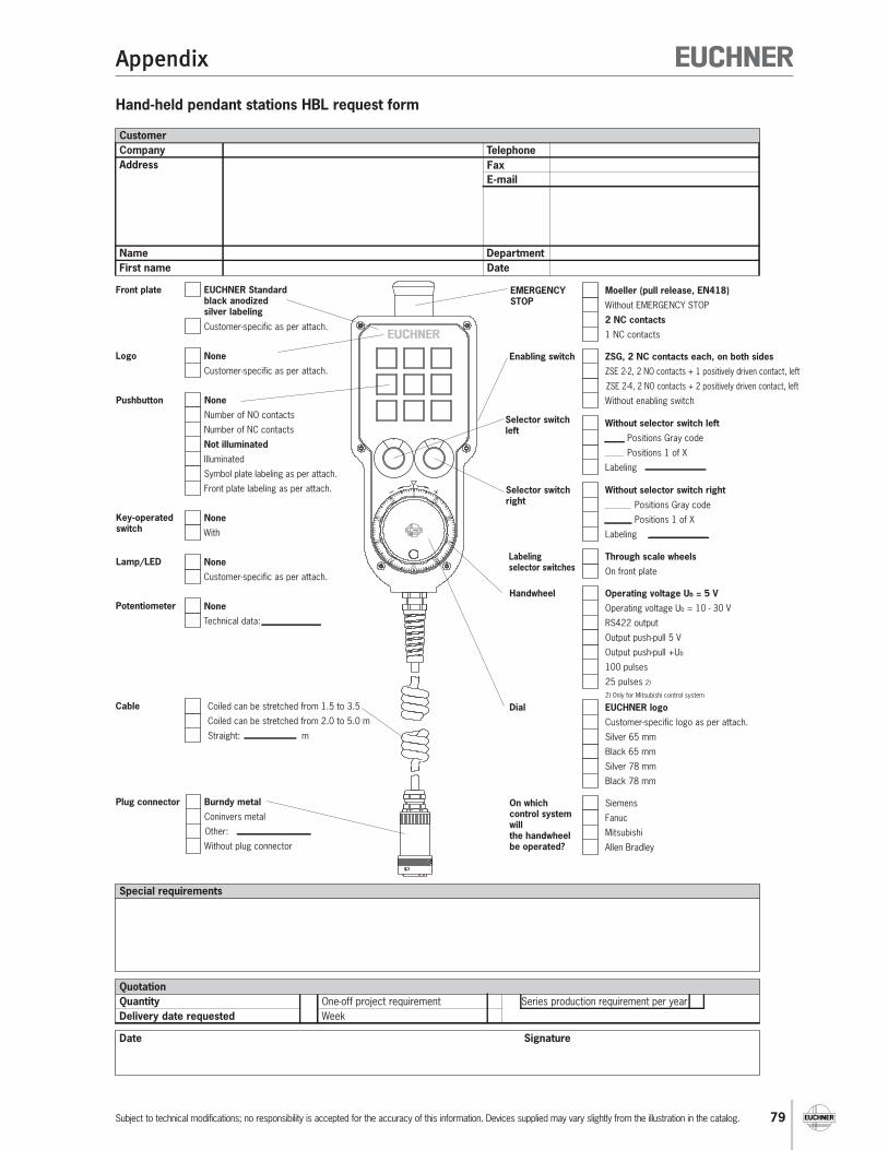
79
Appendix
Subject to technical modifications; no responsibility is accepted for the accuracy of this information. Devices supplied may vary slightly from the illustration in the catalog.
Hand-held pendant stations HBL request form
Customer
Company
Address
Name
First name
Telephone
Fax
Department
Date
Date
Quotation
Delivery date requested
One-off project requirement
Week
Series production requirement per yearQuantity
Signature
Special requirements
Logo None
Customer-specific as per attach.
EMERGENCY STOP
Moeller (pull release, EN418)
Without EMERGENCY STOP
2 NC contacts
1 NC contacts
Key-operatedswitch
None
With
Plug connector Burndy metal
Coninvers metal
Without plug connector
Other:
Handwheel Operating voltage Ub = 5 V
Operating voltage Ub = 10 - 30 V
RS422 output
Output push-pull 5 V
Output push-pull +Ub
100 pulses
25 pulses 2)
2) Only for Mitsubishi control system
On which control system willthe handwheelbe operated?
Siemens
Fanuc
Mitsubishi
Allen Bradley
Labelingselector switches
Through scale wheels
On front plate
Front plate EUCHNER Standardblack anodizedsilver labeling
Customer-specific as per attach.
Pushbutton None
Number of NO contacts
Number of NC contacts
Not illuminated
Symbol plate labeling as per attach.
Illuminated
Front plate labeling as per attach.
Lamp/LED None
Customer-specific as per attach.
Potentiometer None
Technical data:
Cable Coiled can be stretched from 1.5 to 3.5
Coiled can be stretched from 2.0 to 5.0 m
Straight: m
ZSE 2-4, 2 NO contacts + 2 positively driven contact, left
Enabling switch ZSG, 2 NC contacts each, on both sides
ZSE 2-2, 2 NO contacts + 1 positively driven contact, left
Without enabling switch
Selector switch right
Labeling
Positions 1 of X
Positions Gray code
Without selector switch right
Dial EUCHNER logo
Customer-specific logo as per attach.
Silver 65 mm
Black 65 mm
Silver 78 mm
Black 78 mm
Selector switch left
Positions Gray code
Without selector switch left
Labeling
Positions 1 of X

80
Item Index
Item Order No. Page Item Order No. Page
ActiveX modules 067 176 29
ActiveX modules 093 011 17
Blanking plug for fastening hole for
EMERGENCY STOP device083 653 46
Blanking plug for fastening hole for
EMERGENCY STOP device059 622 54
Cable gland M16x1.5 083 641 52
Cable gland Pg 11 073 982 52
Cable gland Pg 13.5 073 983 52
Cable, 12-core, straight, 10000 mm 087 381 51
Cable, 12-core, straight, 3500 mm 087 379 51
Cable, 12-core, straight, 5000 mm 087 380 51
Cable, 12-core, coiled, 3900 mm 086 721 51
Cable, 12-core, coiled, 5400 mm 086 722 51
Cable, 23-core, straight, 10000 mm 087 384 51
Cable, 23-core, straight cable, 3500 mm 087 382 51
Cable, 23-core, straight cable, 5000 mm 087 383 51
Cable, 23-core, coiled, 3900 mm 087 408 51
Cable, 23-core, coiled, 5400 mm 087 409 51
Cable, 35-core, straight, 10000 mm 097 187 51
Cable, 35-core, straight, 3500 mm 097 189 51
Cable, 35-core, straight, 5000 mm 097 188 51
Cable, 35-core coiled, 3900 mm 097 190 51
Cable, 35-core coiled, 5400 mm 097 191 51
Dial 58 mm black 059 276 73
Dial 65 mm black 057 318 73
Dial 65 mm silver 057 314 73
Dial 78 mm black 057 280 73
Dial 78 mm silver 057 272 73
Dial 90 mm black 057 266 73
Dial 90 mm silver 057 268 73
Dial GD60/V10 072 991 73
Dial GE60/V10 072 992 73
EMERGENCY STOP device (rotary release) 096 292 46
EMERGENCY STOP device (pull release) 073 985 54
EMERGENCY STOP device (pull release) 096 298 46
Flange plug 19-pin 092 374 53
Flange socket, 12-pin 086 749 50
Flange socket, 23-pin 074 384 50
Flange socket, 28-pin 074 385 50
Flange socket, 35-pin 074 386 50
Flange socket and short-circuit plug 098 412 53
Front plate F with seal 028 760 73
Front plate for housing HBA with handwheel 083 635 36
Front plate for housing HBA with handwheel 083 636 36
Front plate for housing HBA without handwheel 084 395 36
Front plate for housing HBA without handwheel 084 396 36
Front plate G with seal 028 761 73
Front plate H with seal 028 762 73
Front seal for HBE front plate 072 642 40
Front seal for HBL front plate 072 641 44
Hand-held pendant station HBA - 072 936 072 936 11
Hand-held pendant station HBA - 079 826 079 826 11
Hand-held pendant station HBA - 079 827 079 827 11
Hand-held pendant station HBA - 079 828 079 828 11
Hand-held pendant station HBA - 096 692 096 692 15
Hand-held pendant station HBA - 098 404 098 404 13
Hand-held pendant station HBA - 098 405 098 405 13
Hand-held pendant station HBAS - 072 949 072 949 17
Hand-held pendant station HBAS - 094 594 094 594 17
Hand-held pendant station HBE - 097 335 097 335 19
Hand-held pendant station HBE - 097 336 097 336 21
Hand-held pendant station HBE - 097 337 097 337 23
Index by item designation
Hand-held pendant station HBE - 097 338 097 338 25
Hand-held pendant station HBL - 097 339 097 339 27
Hand-held pendant station HBLS - 072 725 072 725 29
HBA - 083 449 083 449 35
HBA - 083 495 083 495 35
HBA - 083 499 083 499 35
HBA - 086 762 086 762 35
HBA - 095 561 095 561 35
HBA - 095 572 095 572 35
HBA - 095 573 095 573 35
HBA - 095 574 095 574 35
HBE front plate 052 954 40
HBE front plate 052 955 40
HBL front plate 073 139 44
HBL front plate 073 138 44
HKA025S100G12 072 956 64
HKA100S100A05 072 885 64
HKA100S100G05 072 955 64
HKA100S100G24 072 967 64
HKC025S100G12 072 940 62
HKC100S100A05 087 733 62
HKC100S100G05 082 573 62
HKC100S100G24 087 739 62
HKD025S100G12 091 525 60
HKD025V100G12 091 526 60
HKD100S100A05 054 866 60
HKD100S100G05 083 354 60
HKD100S100G24 054 868 60
HKD100V100A05 057 036 60
HKD100V100G05 091 527 60
HKD100V100G24 057 037 60
HKD100X100A05 054 867 60
HKD100X100G12 083 359 60
HKD100X100G24 093 433 60
Holder HBA 072 828 56
Holder HBE 083 445 56
Holder HBL 084 397 56
Housing HBA - 084 445 084 445 33
Housing HBA - 084 450 084 450 33
Housing HBA - 086 155 086 155 33
Housing HBA - 095 562 095 562 33
Housing HBE - 048 429 048 429 39
Housing HBE - 054 982 054 982 39
Housing HBE - 072 626 072 626 39
Housing HBE - 072 627 072 627 39
Housing HBE - 072 629 072 629 39
Housing HBE - 072 984 072 984 39
Housing HBE - 074 973 074 973 39
Housing HBE - 083 489 083 489 39
Housing HBL - 072 630 072 630 43
Housing HBL - 072 631 072 631 43
Housing HBL - 072 632 072 632 43
Housing HBL - 072 983 072 983 43
Housing HBL - 073 098 073 098 43
Housing HBL - 073 109 073 109 43
Housing HBL - 073 113 073 113 43
Housing HBL - 083 484 083 484 43
HWA025T100G12/V10 072 972 66
HWA100T100A05/V10 072 970 66
HWA100T100G05/V10 072 971 66
HWB025T100G12/V05 072 975 68
HWB100T100A05/V05 072 973 68
HWB100T100G05/V05 072 974 68

81
Item Index
Item Order No. Page Item Order No. Page
HWD-072988/V10 072 988 70
HWE-072989/V10 072 989 71
HWF-072990/V10 072 990 72
Illuminated pushbutton, can be individually labeled 074 991 47
Key-operated switch 083 639 48
Manual ActiveX modules 067 178 29
Manual ActiveX modules 093 013 17
Plug connector, 12-pin 086 748 50
Plug connector, 23-pin 074 393 50
Plug connector, 28-pin 074 394 50
Plug connector, 35-pin 074 395 50
Pushbutton, blue button 086 757 47
Pushbutton, green button 086 754 47
Pushbutton, red button 086 753 47
Pushbutton, black button 083 640 47
Pushbutton, white button 086 755 47
Rotary knob 097 141 49
Sealing ring E 054 861 73
Selector switch, 12 detent positions 097 033 49
Selector switch, 16 detent positions 097 034 49
Selector switch, 2 detent positions 097 026 49
Selector switch, 3 detent positions 097 027 49
Selector switch, 4 detent positions 097 028 49
Selector switch, 5 detent positions 097 029 49
Selector switch, 6 detent positions 097 030 49
Selector switch, 7 detent positions 097 031 49
Selector switch, 8 detent positions 097 032 49
Short-circuit plug, 12-pin 087 802 50
Short-circuit plug, 23-pin 083 457 50
Short-circuit plug, 28-pin 083 458 50
Short-circuit plug, 35-pin 083 459 50
ZSE-2 C 1692 070 752 55
ZSE-4 C 1943 083 477 55

82
Item Index
Order No. Item Page Order No. Item Page
Index by order number
028 760 Front plate F with seal 73
028 761 Front plate G with seal 73
028 762 Front plate H with seal 73
048 429 Housing HBE - 048 429 39
052 954 HBE front plate 40
052 955 HBE front plate 40
054 861 Sealing ring E 73
054 866 HKD100S100A05 60
054 867 HKD100X100A05 60
054 868 HKD100S100G24 60
054 982 Housing HBE - 054 982 39
057 036 HKD100V100A05 60
057 037 HKD100V100G24 60
057 266 Dial 90 mm black 73
057 268 Dial 90 mm silver 73
057 272 Dial 78 mm silver 73
057 280 Dial 78 mm black 73
057 314 Dial 65 mm silver 73
057 318 Dial 65 mm black 73
059 276 Dial 58 mm black 73
059 622Blanking plug for fastening hole for
EMERGENCY STOP device54
067 176 ActiveX modules 29
067 178 Manual ActiveX modules 29
070 752 ZSE-2 C 1692 55
072 626 Housing HBE - 072 626 39
072 627 Housing HBE - 072 627 39
072 629 Housing HBE - 072 629 39
072 630 Housing HBL - 072 630 43
072 631 Housing HBL - 072 631 43
072 632 Housing HBL - 072 632 43
072 641 Front seal for HBL front plate 44
072 642 Front seal for HBE front plate 40
072 725 Hand-held pendant station HBLS - 072 725 29
072 828 Holder HBA 56
072 885 HKA100S100A05 64
072 936 Hand-held pendant station HBA - 072 936 11
072 940 HKC025S100G12 62
072 949 Hand-held pendant station HBAS - 072 949 17
072 955 HKA100S100G05 64
072 956 HKA025S100G12 64
072 967 HKA100S100G24 64
072 970 HWA100T100A05/V10 66
072 971 HWA100T100G05/V10 66
072 972 HWA025T100G12/V10 66
072 973 HWB100T100A05/V05 68
072 974 HWB100T100G05/V05 68
072 975 HWB025T100G12/V05 68
072 983 Housing HBL - 072 983 43
072 984 Housing HBE - 072 984 39
072 988 HWD-072988/V10 70
072 989 HWE-072989/V10 71
072 990 HWF-072990/V10 72
072 991 Dial GD60/V10 73
072 992 Dial GE60/V10 73
073 098 Housing HBL - 073 098 43
073 109 Housing HBL - 073 109 43
073 113 Housing HBL - 073 113 43
073 138 HBL front plate 44
073 139 HBL front plate 44
073 982 Cable gland Pg 11 52
073 983 Cable gland Pg 13.5 52
073 985 EMERGENCY STOP device (pull release) 54
074 384 Flange socket, 23-pin 50
074 385 Flange socket, 28-pin 50
074 386 Flange socket, 35-pin 50
074 393 Plug connector, 23-pin 50
074 394 Plug connector, 28-pin 50
074 395 Plug connector, 35-pin 50
074 973 Housing HBE - 074 973 39
074 991 Illuminated pushbutton, can be individually labeled 47
079 826 Hand-held pendant station HBA - 079 826 11
079 827 Hand-held pendant station HBA - 079 827 11
079 828 Hand-held pendant station HBA - 079 828 11
082 573 HKC100S100G05 62
083 354 HKD100S100G05 60
083 359 HKD100X100G12 60
083 445 Holder HBE 56
083 449 HBA - 083 449 35
083 457 Short-circuit plug, 23-pin 50
083 458 Short-circuit plug, 28-pin 50
083 459 Short-circuit plug, 35-pin 50
083 477 ZSE-4 C 1943 55
083 484 Housing HBL - 083 484 43
083 489 Housing HBE - 083 489 39
083 495 HBA - 083 495 35
083 499 HBA - 083 499 35
083 635 Front plate for housing HBA with handwheel 36
083 636 Front plate for housing HBA with handwheel 36
083 639 Key-operated switch 48
083 640 Pushbutton, black button 47
083 641 Cable gland M16x1.5 52
083 653Blanking plug for fastening hole for
EMERGENCY STOP device46
084 395 Front plate for housing HBA without handwheel36
084 396 Front plate for housing HBA without handwheel36
084 397 Holder HBL 56
084 445 Housing HBA - 084 445 33
084 450 Housing HBA - 084 450 33
086 155 Housing HBA - 086 155 33
086 721 Cable, 12-core, coiled, 3900 mm 51
086 722 Cable, 12-core, coiled, 5400 mm 51
086 748 Plug connector, 12-pin 50
086 749 Flange socket, 12-pin 50
086 753 Pushbutton, red button 47
086 754 Pushbutton, green button 47
086 755 Pushbutton, white button 47
086 757 Pushbutton, blue button 47
086 762 HBA - 086 762 35
087 379 Cable, 12-core, straight, 3500 mm 51
087 380 Cable, 12-core, straight, 5000 mm 51
087 381 Cable, 12-core, straight, 10000 mm 51
087 382 Cable, 23-core, straight, 3500 mm 51
087 383 Cable, 23-core, straight, 5000 mm 51
087 384 Cable, 23-core, straight, 10000 mm 51
087 408 Cable, 23-core, coiled, 3900 mm 51
087 409 Cable, 23-core, coiled, 5400 mm 51
087 733 HKC100S100A05 62
087 739 HKC100S100G24 62
087 802 Short-circuit plug, 12-pin 50
091 525 HKD025S100G12 60
091 526 HKD025V100G12 60
091 527 HKD100V100G05 60
092 374 Flange plug, 19-pin 53
093 011 ActiveX modules 17
093 013 Manual ActiveX modules 17
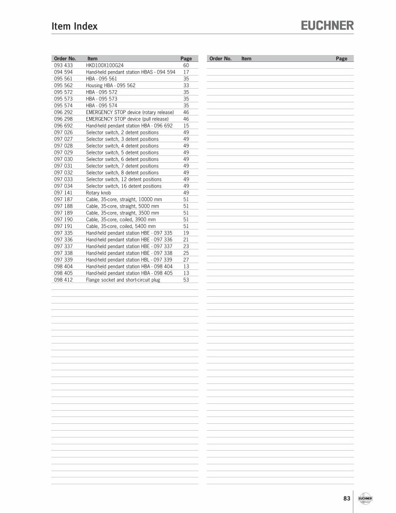
83
Item Index
Order No. Item Page Order No. Item Page
093 433 HKD100X100G24 60
094 594 Hand-held pendant station HBAS - 094 594 17
095 561 HBA - 095 561 35
095 562 Housing HBA - 095 562 33
095 572 HBA - 095 572 35
095 573 HBA - 095 573 35
095 574 HBA - 095 574 35
096 292 EMERGENCY STOP device (rotary release) 46
096 298 EMERGENCY STOP device (pull release) 46
096 692 Hand-held pendant station HBA - 096 692 15
097 026 Selector switch, 2 detent positions 49
097 027 Selector switch, 3 detent positions 49
097 028 Selector switch, 4 detent positions 49
097 029 Selector switch, 5 detent positions 49
097 030 Selector switch, 6 detent positions 49
097 031 Selector switch, 7 detent positions 49
097 032 Selector switch, 8 detent positions 49
097 033 Selector switch, 12 detent positions 49
097 034 Selector switch, 16 detent positions 49
097 141 Rotary knob 49
097 187 Cable, 35-core, straight, 10000 mm 51
097 188 Cable, 35-core, straight, 5000 mm 51
097 189 Cable, 35-core, straight, 3500 mm 51
097 190 Cable, 35-core, coiled, 3900 mm 51
097 191 Cable, 35-core, coiled, 5400 mm 51
097 335 Hand-held pendant station HBE - 097 335 19
097 336 Hand-held pendant station HBE - 097 336 21
097 337 Hand-held pendant station HBE - 097 337 23
097 338 Hand-held pendant station HBE - 097 338 25
097 339 Hand-held pendant station HBL - 097 339 27
098 404 Hand-held pendant station HBA - 098 404 13
098 405 Hand-held pendant station HBA - 098 405 13
098 412 Flange socket and short-circuit plug 53

84
For your Notes

85
Product Catalog
Safety Switches, Metal Housing
Safety Switches NZ/TZ
Safety Switches NX/TX
Safety Switches, Plastic Housing
Safety Switches NM
Safety Switches NP/GP/TP
Safety Switches STM
Safety Switches STP
Non-Contact Safety Switches
Non-Contact Safety Switches CES/CEM,
Transponder Coding
Non-Contact Safety Switches CMS,
Magnetic Coding
Safety Products with integrated Bus Interface
Bolts for Safety Guards
Enabling Switches
Safety Relays
Safety Relays ESM
Modular Safety System ESM-F
Rope Pull Switches
Joystick Switches
Electronic Handwheels
Pendant Stations
Pendant Stations HBA
Pendant Stations HBE/HBL
Electronic-Key-System
Position Switches
Position Switches
Position Switches according to EN 50 041
Precision Multiple Limit Switches
Inductive Limit Switches
Plug Connectors
Trip Rails/Trip Dogs
Inductive Ident Systems
Automation
Safety
ManMachine