Embed Size (px)
Citation preview

Atlona Manuals ScalersAT-HDVS-200-RX
HDBaseT™ Scalerwith HDMI and Analog Audio Outputs
Ethernet-Enabled

AT-HDVS-200-RX 2
Version Release Date Notes
1 01/16 Initial release
2 06/17 New format
Version Information

AT-HDVS-200-RX 3
©2017 Atlona, Inc. All Rights Reserved. All trademarks are the property of their respective owners.Atlona reserves the right to make changes to the hardware, packaging, and documentation without notice.
Thank you for purchasing this Atlona product. We hope you enjoy it and will take an extra few moments to register your new purchase.
Registration only takes a few minutes and protects this product against theft or loss. In addition, you will receive notifications of product updates and firmware. Atlona product registration is voluntary and failure to register will not affect the product warranty.
To register your product, go to http://www.atlona.com/registration
Sales, Marketing, and Customer Support
Welcome to Atlona!
Operating Notes
IMPORTANT: Visit http://www.atlona.com/product/AT-HDVS-200-RX for the latest firmware updates and User Manual.
Main Office
Atlona Incorporated70 Daggett DriveSan Jose, CA 95134United States Office: +1.877.536.3976 (US Toll-free)Office: +1.408.962.0515 (US/International)
Sales and Customer Service HoursMonday - Friday: 6:00 a.m. - 4:30 p.m. (PST)
http://www.atlona.com/
International Headquarters
Atlona International AGRingstrasse 15a8600 DübendorfSwitzerland
Office: +41 43 508 4321
Sales and Customer Service HoursMonday - Friday: 09:00 - 17:00 (UTC +1)
• Consumer Electronics Control (CEC): Atlona has confirmed proper CEC functionality with several current models of Samsung, Panasonic, and Sony displays. However, it is not guaranteed that CEC will work with all displays. Many manufacturers do not support the CEC “off” command, and older displays use proprietary commands. Atlona only supports displays that use the CEC command structure defined in HDMI 1.2a. It is recommended that dealers request an evaluation product from Atlona, before designing a system using the CEC protocol. If this is not possible, then other control methods will need to be considered, in order to control displays using Atlona products.

AT-HDVS-200-RX 4
Atlona, Inc. (“Atlona”) Limited Product Warranty
Coverage
Atlona warrants its products will substantially perform to their published specifications and will be free from defects in materials and workmanship under normal use, conditions and service.
Under its Limited Product Warranty, Atlona, at its sole discretion, will either:
• repair or facilitate the repair of defective products within a reasonable period of time, restore products to their proper operating condition and return defective products free of any charge for necessary parts, labor and shipping.
OR
• replace and return, free of charge, any defective products with direct replacement or with similar products deemed by Atlona to perform substantially the same function as the original products.
OR
• refund the pro-rated value based on the remaining term of the warranty period, not to exceed MSRP, in cases where products are beyond repair and/or no direct or substantially similar replacement products exist.
Repair, replacement or refund of Atlona products is the purchaser’s exclusive remedy and Atlona liability does not extend to any other damages, incidental, consequential or otherwise.
This Limited Product Warranty extends to the original end-user purchaser of Atlona products and is non-transferrable to any subsequent purchaser(s) or owner(s) of these products.
Coverage Periods
Atlona Limited Product Warranty Period begins on the date of purchase by the end-purchaser. The date contained on the end-purchaser ‘s sales or delivery receipt is the proof purchase date.
Limited Product Warranty Terms – New Products
• 10 years from proof of purchase date for hardware/electronics products purchased on or after June 1, 2013.
• 3 years from proof of purchase date for hardware/electronics products purchased before June 1, 2013.
• Lifetime Limited Product Warranty for all cable products.
Limited Product Warranty Terms – Refurbished (B-Stock) Products
• 3 years from proof of purchase date for all Refurbished (B-Stock) hardware and electronic products purchased on or after June 1, 2013.
Remedy
Atlona recommends that end-purchasers contact their authorized Atlona dealer or reseller from whom they purchased their products. Atlona can also be contacted directly. Visit www.atlona.com for Atlona’s contact information and hours of operation. Atlona requires that a dated sales or delivery receipt from an authorized dealer, reseller or end-purchaser is provided before Atlona extends its warranty services. Additionally, a return merchandise authorization (RMA) and/or case number, is required to be obtained from Atlona in advance of returns.
Atlona requires that products returned are properly packed, preferably in the original carton, for shipping. Cartons not bearing a return authorization or case number will be refused. Atlona, at its sole discretion, reserves the right to reject any products received without advanced authorization. Authorizations can be requested by calling 1-877-536-3976 (US toll free) or 1-408- 962-0515 (US/international) or via Atlona’s website at www.atlona.com.
Exclusions
This Limited Product Warranty excludes:• Damage, deterioration or malfunction caused by any alteration, modification, improper use, neglect, improper
packaging or shipping (such claims must be presented to the carrier), lightning, power surges, or other acts of nature.

AT-HDVS-200-RX 5
• Damage, deterioration or malfunction resulting from the installation or removal of this product from any installation, any unauthorized tampering with this product, any repairs attempted by anyone unauthorized by Atlona to make such repairs, or any other cause which does not relate directly to a defect in materials and/or workmanship of this product.
• Equipment enclosures, cables, power supplies, batteries, LCD displays, and any accessories used in conjunction with the product(s).
• Products purchased from unauthorized distributors, dealers, resellers, auction websites and similar unauthorized channels of distribution.
Disclaimers
This Limited Product Warranty does not imply that the electronic components contained within Atlona’s products will not become obsolete nor does it imply Atlona products or their electronic components will remain compatible with any other current product, technology or any future products or technologies in which Atlona’s products may be used in conjunction with. Atlona, at its sole discretion, reserves the right not to extend its warranty offering in instances arising outside its normal course of business including, but not limited to, damage inflicted to its products from acts of god.
Limitation on Liability
The maximum liability of Atlona under this limited product warranty shall not exceed the original Atlona MSRP for its products. To the maximum extent permitted by law, Atlona is not responsible for the direct, special, incidental or consequential damages resulting from any breach of warranty or condition, or under any other legal theory. Some countries, districts or states do not allow the exclusion or limitation of relief, special, incidental, consequential or indirect damages, or the limitation of liability to specified amounts, so the above limitations or exclusions may not apply to you.
Exclusive Remedy
To the maximum extent permitted by law, this limited product warranty and the remedies set forth above are exclusive and in lieu of all other warranties, remedies and conditions, whether oral or written, express or implied. To the maximum extent permitted by law, Atlona specifically disclaims all implied warranties, including, without limitation, warranties of merchantability and fitness for a particular purpose. If Atlona cannot lawfully disclaim or exclude implied warranties under applicable law, then all implied warranties covering its products including warranties of merchantability and fitness for a particular purpose, shall provide to its products under applicable law. If any product to which this limited warranty applies is a “Consumer Product” under the Magnuson-Moss Warranty Act (15 U.S.C.A. §2301, ET SEQ.) or other applicable law, the foregoing disclaimer of implied warranties shall not apply, and all implied warranties on its products, including warranties of merchantability and fitness for the particular purpose, shall apply as provided under applicable law.
Other Conditions
Atlona’s Limited Product Warranty offering gives legal rights, and other rights may apply and vary from country to country or state to state. This limited warranty is void if (i) the label bearing the serial number of products have been removed or defaced, (ii) products are not purchased from an authorized Atlona dealer or reseller. A comprehensive list of Atlona’s authorized distributors, dealers and resellers can be found at www.atlona.com.
Atlona, Inc. (“Atlona”) Limited Product Warranty

AT-HDVS-200-RX 6
FCC StatementFCC Compliance and Advisory Statement: This hardware device complies with Part 15 of the FCC rules. Operation is subject to the following two conditions: 1) this device may not cause harmful interference, and 2) this device must accept any interference received including interference that may cause undesired operation. This equipment has been tested and found to comply with the limits for a Class A digital device, pursuant to Part 15 of the FCC Rules. These limits are designed to provide reasonable protection against harmful interference in a commercial installation. This equipment generates, uses, and can radiate radio frequency energy and, if not installed or used in accordance with the instructions, may cause harmful interference
to radio communications. However there is no guarantee that interference will not occur in a particular installation. If this equipment does cause harmful interference to radio or television reception, which can be determined by turning the equipment off and on, the user is encouraged to try to correct the interference by one or more of the following measures: 1) reorient or relocate the receiving antenna; 2) increase the separation between the equipment and the receiver; 3) connect the equipment to an outlet on a circuit different from that to which the receiver is connected; 4) consult the dealer or an experienced radio/TV technician for help. Any changes or modifications not expressly approved by the party responsible for compliance could void the user’s authority to operate the equipment. Where shielded interface cables have been provided with the product or specified additional components or accessories elsewhere defined to be used with the installation of the product, they must be used in order to ensure compliance with FCC regulations.
1. Read these instructions.
2. Keep these instructions.
3. Heed all warnings.
4. Follow all instructions.
5. Do not use this product near water.
6. Clean only with a dry cloth.
7. Do not block any ventilation openings. Install in accordance with the manufacturer’s instructions.
8. Do not install or place this product near any heat sources such as radiators, heat registers, stoves, or other apparatus (including amplifiers) that produce heat.
9. Do not defeat the safety purpose of a polarized or grounding-type plug. A polarized plug has two blades with one wider than the other. A grounding type plug has two blades and a third grounding prong. The wide blade or the third prong are provided for your safety. If the provided plug does not fit into your outlet, consult an electrician for replacement of the obsolete outlet.
10. Protect the power cord from being walked on or pinched particularly at plugs, convenience receptacles, and the point where they exit from the product.
11. Only use attachments/accessories specified by Atlona.
12. To reduce the risk of electric shock and/or damage to this product, never handle or touch this unit or power cord if your hands are wet or damp. Do not expose this product to rain or moisture.
13. Unplug this product during lightning storms or when unused for long periods of time.
14. Refer all servicing to qualified service personnel. Servicing is required when the product has been damaged in any way, such as power-supply cord or plug is damaged, liquid has been spilled or objects have fallen into the product, the product has been exposed to rain or moisture, does not operate normally, or has been dropped.
CAUTION: TO REDUCT THE RISK OFELECTRIC SHOCK
DO NOT OPEN ENCLOSURE OR EXPOSETO RAIN OR MOISTURE.
NO USER-SERVICEABLE PARTSINSIDE REFER SERVICING TO
QUALIFIED SERVICE PERSONNEL.
CAUTIONRISK OF ELECTRIC SHOCK
DO NOT OPEN
The exclamation point within an equilateral triangle is intended to alert the user to the presence of important operating and maintenance instructions in the literature accompanying the product.
The information bubble is intended to alert the user to helpful or optional opera-tional instructions in the literature accompanying the product.
Important Safety Information

AT-HDVS-200-RX 7
Introduction 8
Features 8
Package Contents 8
Panel Description 9
Installation 10RS-232 Connector 10Audio Connector 10Relay Connector 11Power Connector 11Connection Instructions 12Connection Diagram 12
Menu System 13Accessing the On-Screen Display 13
Input Select 14Input Resolution 14Output Resolution 15Picture Adjust 15Aspect 16Overscan 16Audio 17OSD 18Others 19Information 20System Setup 22
The Web GUI 23Introduction to the Web GUI 23
Menu Bar 24Toggles 25Sliders 25Buttons 25
Info page 26Video page 27
Input 27Output 27
Audio page 29Picture page 30RS-232 page 31Config page 32System page 33
Relay 33System 33
Commands 35
Appendix 53Updating the Firmware 53
Using the Web GUI 53Using USB 54
Default Settings 56Specifications 58
Index 60
Table of Contents

AT-HDVS-200-RX 8
The Atlona AT-HDVS-200-RX is an HDBaseT receiver and HD scaler for video signals up to 1080p, plus embedded audio, control, and Ethernet over distances up to 330 feet (100 meters). The HDVS-200-RX is designed for use with the HDVS-200-TX switching transmitters, but can also be used with Atlona switchers, matrix switchers, and distribution amplifiers with HDBaseT outputs. The HDVS-200-TX and HDVS-200-RX together serve as a compact, automated AV system with the convenience of automatic input selection, display control, and HD scaling. The HDVS-200-RX remotely powers the HDVS-200-TX through Power over Ethernet (PoE).
The HDVS-200-RX offers advanced scaling capabilities including image adjustment capability, and a feature for automatically matching incoming signals to the display’s native resolution. Integrated scaling and video processing help optimize image quality and switching performance. This receiver also features audio de-embedding, and third-party TCP/IP and RS-232 control of the scaler and display. Additionally, the HDVS-200-RX includes contact closure ports for controlling a motorized screen or display lift.
1 x AT-HDVS-200-RX2 x Captive screw connectors, 5-pin1 x Captive screw connectors, 3-pin1 x Captive screw connectors, 2-pin1 x Mounting brackets1 x 48V DC power supply1 x Installation Guide
Introduction
Features
Package Contents
• HD video scaler with HDMI® output and input resolution control
• Ideal for an HDVS-200-TX switching transmitter and Atlona HDBaseT-equipped switchers
• HDBaseT™ receiver for AV, Ethernet, power, and control up to 330 feet (100 meters)
• Automatic display control (when used with the HDVS-200-TX or compatible Atlona switcher)
• TCP/IP and RS-232 scaler and display control
• Contact closure for screen or display lift control
• Audio de-embedding
• Local AC powering – PoE (Power over Ethernet) source for HDVS-200-TX
• On-screen display with front panel menu controls

AT-HDVS-200-RX 9
MENURS-232
DC 48V LAN HDBaseT IN HDMI OUTFW
C1 C2COM
21RLAUDIO
PW
LINK
AUTO
AT-HDVS-200-RX
RX TX TX RX
MENURS-232
DC 48V LAN HDBaseT IN HDMI OUTFW
C1 C2COM
21RLAUDIO
PW
LINK
AUTO
AT-HDVS-200-RX
RX TX TX RX1 2 3 4 6 10 11
87 9 12 135
1 AUDIO Connect the included 5-pin Phoenix block from this connector to an audio amplifier.
2 RS-232 Use the included 5-pin captive screw connector to connect up to two RS-232 controllers or automation systems. Port 1 is used for controlling a display or other sink device. Port 2 is used for controlling the AT-HDVS-200-RX.
3 MENU Press this button to display the built-in On-Screen Display (OSD).
4 AUTO Press this button to perform an auto-adjust on VGA signals, connected to the transmitter. This feature automatically corrects the clock and phase of the VGA source.
5 Cursor buttons Press these buttons to select items within the OSD.
6 PW This LED indicator will glow bright green when the scaler is powered.
7 LINK This LED indicator will glow bright amber when a link is established between the transmitter and receiver.
8 DC 48V Connect the included 48V DC power supply to this power receptacle.
9 LAN Connect an Ethernet cable from this port to the network.
10 HDBaseT IN Use an Ethernet cable to connect an HDBaseT PoE transmitter to this port.
11 RELAY Connect the included 3-pin captive screw connector to this port to control screens, drapes, lights, or other devices.
12 FW Connect a mini USB type-B cable to this port to update the firmware. Refer to Updating the Firmware (page 53) for more information.
13 HDMI OUT Connect an HDMI cable from this port to a display or other sink device.
Front Rear
Panel Description

AT-HDVS-200-RX 10
GND
GND
RX
TX
RX
TX
The AT-HDVS-200-RX provides two RS-232 ports. Port 1 is used for controlling a display or other sink device. Port 2 is used to control the AT-HDVS-200-RX. This step is optional.
1. Use wire strippers to remove a portion of the cable jacket.
2. Remove at least 3/16” (5 mm) from the insulation of the RX, TX, and GND wires.
3. Insert the TX, RX, and GND wires into correct terminal on the included Phoenix block. If using non-tinned stranded wire, presss the orange tab, above the terminal, while inserting the exposed wire. Repeat this step for the TX, RX, and GND connections. The illustration below, shows how to connect both RS-232 cables.
RS-232 1
RS-232 2
RS-232 Connector
Installation
The AUDIO OUT connector on the AT-HDVS-200-RX provides the connection of either balanced or unbalanced audio outputs using XLR connectors. Use the included 5-pin Phoenix terminal block. Balanced audio connections use two signal wires and a ground to minimize interference in audio signals. Unbalanced audio connections use one signal wire and a ground and are used if system components don’t support balanced signals.
Audio Connector
1 2
3
1 2
3
GND GND
+- +
-
1 2
3
1 2
3
GND GND
+- +
-
Balanced
Unbalanced

AT-HDVS-200-RX 11
Power Connector
Relay Connector
Locate the included orange Phoenix terminal block and wire the included power supply to the block, as shown below. Do not use high-torque devices, when securing the wires to the Phoenix terminal block, as this may damage the screws and/or block.
1. Insert the wires into the correct terminal on the included Phoenix block, as shown below.
2. Tighten the screws to secure the wires. Do not use high-torque devices as this may damage the screws and/or connector block.
Black
White
48V DCpower supply
Installation
The AT-HDVS-200-RX provides a RELAY port, allowing the control of screens, curtains, and other devices. Use a 48 V DC relay with no more than 1 A current draw.
When the AT-HDVS-200-RX is powered-on or rebooted, C1 and C2 are set to the Normally Open (NO) state.
C2
COM
C1

AT-HDVS-200-RX 12
Installation
Connection Diagram
NOTE: The AT-HDVS-200-RX is designed to be used with the AT-HDVS-200-TX.
Connection Instructions
1. Use an HDMI cable to connect an HDMI display to the HDMI OUT port on the unit.
2. Connect an Ethernet cable, up to 230 feet (70 meters), from the HDBaseT IN port on the unit to a PoE-compatible transmitter (not included). Ethernet cables should use EIA/TIA-568B termination.
3. Connect an Ethernet cable, up to 330 feet (100 meters), from the LAN port to the network.
4. Optionally connect the RS-232 1 port to a display or other sink device. Connect the RS-232 2 port to an automation control system.
5. Connect the included power supply to the DC 48V port.
IMPORTANT: The included 48 V DC power supply should always be connected to the AT-HDVS-150-RX, for proper operation.
PW
HDMI
INPUT
DISPLAY
v
v
AT-HDVS-200-TX
VOL
HDMI IN 1
VGA IN
AUDIO IN
1
2
VGA
CO
MN
CN
OC
OM
NC
NO
CO
MN
CN
OC
OM
NC
NO
+12VS
IGG
ND
+12VS
IGG
ND
+12VS
IGG
ND
+12VS
IGG
ND
1
COMPONENT
HDMI
1
2
3
4
5
6
SERIAL 1
IR OUT
SERIAL 2
L
RDIGITAL
COAX OUT
AUDIO OUT
AUDIO IN
ETHERNET
23
4
VIDEO OUT
48V DC
FACTORY
RESET
Control
Control
HDBaseT
HDMI
HDMI
Audio (L/R)
HDMI
VGA
AT-HDVS-200-TX
Laptop
Laptop
Desktop PC
AutomationControlSystem
AT-HDVS-200-RX
Projector
ProjectorScreen
Audio Amplifier
SOURCE
: DVD
AAX DE
C
BNE XO
R
USB
USB
USB
MENU
RS-232 2
1
R
LAUDIO
PW
LINK
AUTO
AT-HDVS-200-RX
RX TXTX RX
Ethernet
LAN

AT-HDVS-200-RX 13
The AT-HDVS-200-RX includes a built-in On-Screen Display (OSD) menu system to manage and control all video features.
1. Press and release the MENU button to display the OSD.
2. Press the UP/DN buttons to highlight the various menu options. The currently selected menu item will be highlighted with a blue cursor bar. Press the UP button to move the cursor up through the menu system and press the DN button to move down.
3. Once the desired menu item is highlighted, press the MENU button to access its settings. Within the menu item, the current setting will always be highlighted in green. In this illustration, the Aspect menu item indicates that Full is the currently selected aspect ratio setting. Refer to Aspect (page 16) for more information.
MENURS-232
DC 48V LAN HDBaseT IN HDMI OUTFW
C1 C2COM
21RLAUDIO
PW
LINK
AUTO
AT-HDVS-200-RX
RX TX TX RX
MENURS-232
DC 48V LAN HDBaseT IN HDMI OUTFW
C1 C2COM
21RLAUDIO
PW
LINK
AUTO
AT-HDVS-200-RX
RX TX TX RX
MENURS-232
DC 48V LAN HDBaseT IN HDMI OUTFW
C1 C2COM
21RLAUDIO
PW
LINK
AUTO
AT-HDVS-200-RX
RX TX TX RX
Aspect
Full16:9 TV16:10 TV 4:3 TVKeep RatioMenu Back
Accessing the On-Screen Display
Main Menu
Input SelectInput ResolutionOutput ResolutionPicture AdjustAspectOverscanAudioOSDOthersInformationSystem ResetMenu Exit
Main Menu
Input SelectInput ResolutionOutput ResolutionPicture AdjustAspectOverscanAudioOSDOthersInformationSystem ResetMenu Exit
Current setting
Cursor
Menu System

AT-HDVS-200-RX 14
Menu System
Selects the desired input.
1. Under the Main Menu, highlight the Input Select menu item using the UP/DN buttons on the front panel.
2. Press the MENU button.
3. The Input Select menu will be displayed.
4. Press the UP/DN buttons to highlight the desired input.
5. Press the MENU button to confirm the selection.
6. Press the Menu Back option to return to the Main Menu.
Input Select
Input Resolution
Selects the desired input resolution.
1. Under the Main Menu, highlight the Input Select menu item using the UP/DN buttons on the front panel.
2. Press the MENU button.
3. The Input Resolution menu will be displayed.
4. Press the UP/DN buttons to highlight the desired input.
5. Press the MENU button to confirm the selection and display the list of available input resolutions.
6. Press the UP/DN buttons to select the desired resolution.
7. Press the MENU button to confirm the selection.
8. Press the Menu Back option to return to the Main Menu.
Input Select
HDMIVGAMenu Back
Input Resolution
HDMIVGAMenu Back
Input Resolution
1280x8001920x10801024x7681280x7201920x12001366x768800x6001600x900NativeMenu Back

AT-HDVS-200-RX 15
Menu System
Selects the desired output resolution. The default output resolution is 720p (1280x720). The Output Resolution menu consists of three pages.
1. Under the Main Menu, highlight the Output Resolution menu item using the UP/DN buttons on the front panel.
2. Press the MENU button.
3. The Output Resolution menu will be displayed.
4. Press the UP/DN buttons to highlight the desired resolution.
5. Press the MENU button to confirm the selection.
6. Scroll down and select the Menu Back option, under Output Resolution 3, then press the MENU button to return to the Main Menu.
Output Resolution 1
720p30720p50720p59.94720p601080i501080i59.941080i601080p23.981080p241080p251080p29.971080p30
Output Resolution
Provides custom adjustment of picture brightness, contrast, saturation, hue, sharpness, and color space.
1. Under the Main Menu, highlight the Output Resolution menu item using the UP/DN buttons on the front panel.
2. Press the MENU button.
3. The Picture Adjust menu will be displayed.
4. Press the UP/DN buttons to highlight the desired option.
5. Press the MENU button to confirm the selection.
6. The current value will be highlighted in green and surrounded by brackets and two arrowheads.
Picture Adjust
Brightness 64Contrast 64 Saturation 64Hue 64Sharpness 32Picture ResetMenu Back
Picture Adjust

AT-HDVS-200-RX 16
Menu System
Aspect
Allows the aspect ratio of the output image to be changed.
1. Under the Main Menu, highlight the Output Resolution menu item using the UP/DN buttons on the front panel.
2. Press the MENU button.
3. The Aspect menu will be displayed.
4. Press the UP/DN buttons to highlight the desired aspect ratio.
5. Press the MENU button to confirm the selection.
6. Select the Menu Back option, then press the MENU button, to return to the Main Menu.
Aspect
Full16:9 TV16:10 TV 4:3 TVKeep RatioMenu Back
Setting Description
Full The output signal will be scaled to fill the screen.
16:9 TV The output signal will be scaled to fit as 16:9.
16:10 TV The output signal will be scaled to fit as 16:10.
4:3 TV Output signal will be set to 4:3. If the input is HD, approximately 35% of the total horizontal resolution will be lost.
Keep Ratio The input aspect ratio is preserved on the output.
Adjusts the overscan setting of the output video signal. By default, overscan is disabled.
1. Under the Main Menu, highlight the Overscan menu item using the UP/DN buttons on the front panel.
2. Press the MENU button.
3. The Overscan menu will be displayed.
4. Press the UP/DN buttons to highlight the Enable option.
5. Press the MENU button to change the Enable value
Overscan
Enable [No ]H Size % 0V Size % 0Menu Back
Overscan
Enable Yes H Size % 0V Size % 0Menu Back
Overscan

AT-HDVS-200-RX 17
Menu System
6. When overscan is enabled, the H Size % and V Size % fields can be adjusted. Press the UP/DN buttons to highlight the desired field.
7. Press the MENU button to select the field.
8. Press the UP/DN buttons to change the value. Press the UP button to increase the value; press the DN button to decrease the value.
9. Press the MENU button to confirm the change.
10. Highlight the Menu Back option, then press the MENU button to return to the Main Menu.
The Audio menu allows adjustment of all audio settings.
1. Under the Main Menu, highlight the Audio menu item using the UP/DN buttons on the front panel.
2. Press the MENU button.
3. The Audio menu will be displayed.
Audio
HDMI Audio EnableL/R Audio EnableMute OffVolume 0dBTreble 0Bass 0Menu Back
Audio
Setting Description
HDMI Audio Controls the HDMI audio, only. Set to Disable to mute the HDMI audio.
L/R Audio Toggles the analog audio output Enable or Disable. Set to Disable to mute the analog audio output.
Mute Provides muting of both HDMI and analog audio outputs. Set this value to Disable to mute all audio.
Volume Controls the output volume. This value can be set from -80 dB to 0dB.
Treble Set the amount of treble applied to the output. Both HDMI and analog audio are affected. This value can be set from -12 to +15.
Treble Set the amount of bass applied to the output. Both HDMI and analog audio are affected. This value can be set from -12 to +15.
4. Press the UP/DN buttons to highlight the desired option.
5. Press the MENU button to confirm the selection. The current value will be highlighted in green and surrounded by brackets and two arrowheads.
7. Press the UP/DN buttons to select the desired value. Press the UP button to increase the value; press DN to decrease the value.
8. Press the MENU button to confirm the value.
9. Highlight the Menu Back option, then press the MENU button to return to the Main Menu.

AT-HDVS-200-RX 18
Menu System
OSD
Position Left TopTransparency 12Info. Timer 10Menu Timer 20Info. Display AutoMenu Display AutoBackground GreyMenu Back
OSD
Adjusts the appearance and position of the On-Screen Display (OSD) on the screen.
1. Under the Main Menu, highlight the Audio menu item using the UP/DN buttons on the front panel.
2. Press the MENU button. The OSD menu will be displayed.
3. Press the UP/DN buttons to highlight the desired option.
Setting Description
Position Sets the position of the OSD on the display. The following options are available:
• Left Top• Right Top• Right Bottom• Left Bottom• Center
Transparency Adjusts the transparency setting of the OSD.• Range: 5 to 100
Info. Timer The duration, in seconds, of how long the Info Display screen is displayed.
• Range: 5 to 100
Menu Timer The duration, in seconds, of how long the OSD remains on the screen, after no activity.
• Range: 5 to 100
Info. Display Adjusts the display settings of the Info Display screen, which indicates the input and output resolution. Refer to the illustration below for an example of the Info Display screen. The following options are available:
• Auto - Automatically displays the Info Display screen when a change is made to the input or output signal. The screen will automatically be hidden after approximately five seconds.
• Off - Prevents the Info Display screen from being displayed.• On - The Info Display screen is always displayed.
Menu Display Controls the behavior of the main menu after the MENU button is pressed.
• Auto - After the MENU button is pressed, the Main Menu will be displayed for the length of time, specified in the Menu Timer field.
• On - Overrides the Menu Timer value. To exit the Main Menu, the Menu Exit option must be selected, within the Main Menu.

AT-HDVS-200-RX 19
Menu System
4. Press the MENU button to confirm the selection.
5. The current value will be highlighted in green and surrounded by brackets and two arrowheads.
6. Press the UP/DN buttons to change the value. For settings that contain a value, press the UP button to increase the value; press the DN button to decrease the value.
7. Press the MENU button to confirm the change.
8. Highlight the Menu Back option, then press the MENU button to return to the Main Menu.
This menu provides control for various other settings, such as auto-switching, HDCP, and vertical mirroring.
1. Under the Main Menu, highlight the Others menu item using the UP/DN buttons on the front panel.
2. Press the MENU button. The Others menu will be displayed.
3. Press the UP/DN buttons to highlight the desired option.
Others
Display HDCP CompliantIn Auto Switch OnVGA Auto AdjustMirror-V OffASP Background GreyMenu Back
Others
Setting Description
Display HDCP Provides control over the transmission of HDCP content for the HDMI IN port on the transmitter (TX). The following options are available:
• Compliant - Reports to the source that the AT-HDVS-200-RX is an HDCP-compliant sink device.
• Noncompliant - Reports to the source that the AT-HDVS-200-RX is an HDCP-compliant sink device.
• Auto - Automatically detects the presence of HDCP-compliant sink devices. If an HDCP-compliant display is detected, then HDCP content will be sent. Otherwise, non-HDCP content will be sent.
Setting Description
Background Sets the background color of the OSD. The following options are available:
• Grey• Cyan• Magenta• Yellow
NOTE: Some source devices will enable HDCP if an HDCP-compliant display (sink) is detected. However, there may be applications where sending HDCP content is not desired. This feature does not provide decryption of HDCP content to non-HDCP sink devices
OSD
Position Left TopTransparency 12Info. Timer 10Menu Timer 20Info. Display AutoMenu Display AutoBackground GreyMenu Back

AT-HDVS-200-RX 20
Menu System
Setting Description
In Auto Switch Enables or disables auto-switching. The following options are available:• On - Enables auto-switching.• Off - Disables auto-switching.
VGA Auto Adjust Automatically tunes the phase and clock of the VGA signal.
Mirror-V Vertically flips the output signal. The default setting is Off. The following options are available:
• On - Vertically flips the output image.• Off - The output image is unaltered.
ASP Background Changes the color of background bars when changing the aspect ratio of the output image. The default color is Black. The following options are available:
• Black• Grey
The Information menu displays current information about the AT-HDVS-200-RX. The Information menu consists of two pages. None of the fields within this menu can be edited.
1. Under the Main Menu, highlight the Information menu item using the UP/DN buttons on the front panel.
2. Press the MENU button.
3. The Information menu will be displayed.
4. Press and release the MENU button to view the next two pages.
5. Press the MENU button again to return to the Main Menu.
Information
Source HDMI Name Intel Product 9xxxx
Sink HDMI VSC Model VA2465 SERIES Native1 1920x1200 Native2 NoneF/W Ver MCU TX:v1.1.17 RX:v1.1.17HDBT 1.30.92.1 1.31.31.5 Next Page
Information
IP Address TX: 192.168.1.117 RX: 192.168.1.123Menu Back
Information
Source DetectionHV Total 1344x806HV Display 1024x768HV Polarity Neg / NegScan Mode ProgressiveType HDMI -Audio-HDCP No Type LPCMClock On SR 48KSync On FIFO OKIdentity 1024x768p60Next Page
Information

AT-HDVS-200-RX 21
Menu System
Setting Description
Source The current input source that is displayed. The source will be displayed as HDMI or VGA.
Name The name of the source, if available.
Product The product name, if available.
Sink Contains the manufacturer’s abbreviation of the sink.
Model Displays the model of the display.
Native1 The native (preferred) timing for the display.
Native2 Displays any detailed (alternate) timing information for the display.
MCU TX / RX Indicates the firmware version of both the transmitter (TX) and receiver (RX). If the TX is not connected, then “Unknown” will be listed next to the TX field.
HDBT Displays the version of HDBaseT on the transmitter and the receiver.
HV Total The total number of horizonal and vertical pixels.
HV Display The display resolution.
HV Polarity Polarity of both the horizontal and vertical sync pulse.
Scan Mode The scan mode - either progressive or interlaced.
Type The type of video signal.
HDCP Indicates whether or not if HDCP content is present.
Clock Indicates whether the source status of the TMDS clock is detected (On) or has been lost (Off).
Sync Indicates whether the source status of the TMDS sync is detected (On) or has been lost (Off).
Identity Displays the detected resolution of the source.
Type (Audio) Displays the audio format.
SR (Audio) Displays the sampling rate of the audio signal.
FIFO (Audio) Displays the status of the FIFO audio buffer.
TX The IP address of the transmitter.
RX The IP address of the receiver.

AT-HDVS-200-RX 22
Menu System
The System Reset menu provides the ability to reset the AT-HDVS-200-RX to factory-default settings.
1. Under the Main Menu, highlight the System Reset menu item using the UP/DN buttons on the front panel.
2. Press the MENU button.
3. The System Setup menu will be displayed.
4. Press the UP/DN buttons to highlight the desired option.
5. Press the MENU button to confirm the selection.
6. Highlight the Menu Back option, then press the MENU button to return to the Main Menu.
System Setup
Factory Reset NoMCU F/W Update NoHDBT F/W Update NoMenu Back
System Setup
Setting Description
Factory Reset Resets the AT-HDVS-200-RX to factory-default settings. The following options are available:
• No - Cancels the factory-reset procedure.• Yes - Proceeds with the factory-reset procedure.
MCU F/W Update This options allows the firmware to be updated. After selecting this item, use one of the following options:
• No - Cancels the update procedure.• Yes - Proceeds with the update procedure.
HDBT F/W Update This options allows the HDBaseT firmware to be updated. After selecting this item, use one of the following options:
• No - Cancels the update procedure.• Yes - Proceeds with the update procedure.
AT-HDVS-200-RX 23
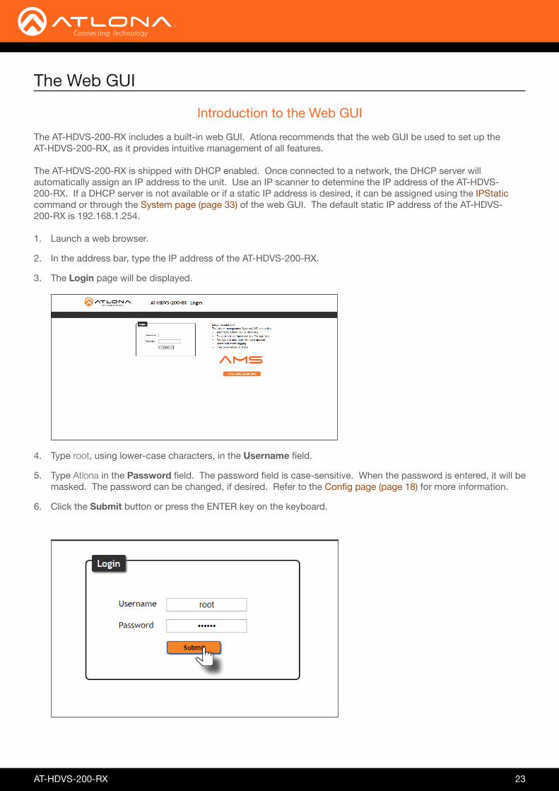
The AT-HDVS-200-RX includes a built-in web GUI. Atlona recommends that the web GUI be used to set up the AT-HDVS-200-RX, as it provides intuitive management of all features.
The AT-HDVS-200-RX is shipped with DHCP enabled. Once connected to a network, the DHCP server will automatically assign an IP address to the unit. Use an IP scanner to determine the IP address of the AT-HDVS-200-RX. If a DHCP server is not available or if a static IP address is desired, it can be assigned using the IPStatic command or through the System page (page 33) of the web GUI. The default static IP address of the AT-HDVS-200-RX is 192.168.1.254.
Introduction to the Web GUI
1. Launch a web browser.
2. In the address bar, type the IP address of the AT-HDVS-200-RX.
3. The Login page will be displayed.
4. Type root, using lower-case characters, in the Username field.
5. Type Atlona in the Password field. The password field is case-sensitive. When the password is entered, it will be masked. The password can be changed, if desired. Refer to the Config page (page 18) for more information.
6. Click the Submit button or press the ENTER key on the keyboard.
The Web GUI

AT-HDVS-200-RX 24
7. The Info page will be displayed.
Menu Bar
The dark-colored bar, near the top of the screen, is the menu bar. When the mouse is moved over each menu element, it will be highlighted in light orange. Once the desired menu element is highlighted, click the left mouse button to access the settings within the menu.
In this example, clicking Video, in the menu bar, will display the Video page.
Menu bar
The Web GUI

AT-HDVS-200-RX 25
Several settings within the Web GUI use toggles, which enable, disable, or assign one of two settings. Generally, when the toggle is blue, it means that the feature is enabled or ON. If a feature is disabled, then the toggle will appear gray and be labeled as OFF. Toggle buttons may also indicate its current setting and, when enabled or set to a particular state, may also provide access to another set of controls or text fields within the Web GUI, as shown with the IP Mode toggle.
Toggles
Sliders
Click and drag slider controls to change their value.
Buttons are used to execute an action or setting. Several pages within the Web GUI include a Save button. Clicking the Save button will apply and save all settings in the current page. Other buttons, such as the Factory Defaults button, under the System page, will reset the AT-HDVS-200-RX to factory-default settings.
Buttons
The Web GUI
AT-HDVS-200-RX 26
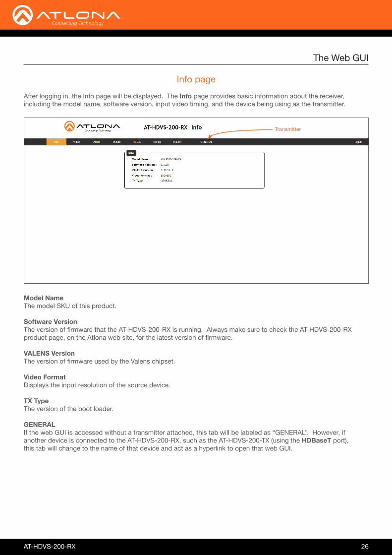
After logging in, the Info page will be displayed. The Info page provides basic information about the receiver, including the model name, software version, input video timing, and the device being using as the transmitter.
Info page
Model Name The model SKU of this product.
Software Version The version of firmware that the AT-HDVS-200-RX is running. Always make sure to check the AT-HDVS-200-RX product page, on the Atlona web site, for the latest version of firmware.
VALENS Version The version of firmware used by the Valens chipset.
Video Format Displays the input resolution of the source device.
TX Type The version of the boot loader.
GENERAL If the web GUI is accessed without a transmitter attached, this tab will be labeled as “GENERAL”. However, if another device is connected to the AT-HDVS-200-RX, such as the AT-HDVS-200-TX (using the HDBaseT port), this tab will change to the name of that device and act as a hyperlink to open that web GUI.
The Web GUI
Transmitter

AT-HDVS-200-RX 27
The Video page is divided into two sections: Input and Output. The Input section allows the preferred input timing to be selected as well as a button to perform an auto-adjust of the VGA signal at the transmitter. The Output section provides options to control the output resolution, aspect ratio, and overscan.
Video page
The Web GUI
Prefer Timing (HDMI) Click this drop-down list to select the desired input timing. VGA Adjust In most situations, adjustment of the VGA signal should not necessary. However, if the VGA signal does not appear correctly, click the Adjust button to automatically correct the clock and phase.
Format Click this drop-down list to select the desired output timing.
Input
Output
Available Input Timings
800x600 1024x768 1280x720
1280x800 1366x768 1600x900
1920x1080 1920x1200 Native
Output Resolutions
800x600 1024x768 1280x800 1280x1024
1366x768 1400x105 1600x900 1600x1200

AT-HDVS-200-RX 28
The Web GUI
Output Resolutions
1680x1050 1920x1200 720p25 720p29.97
720p30 720p50 720p59.94 720p60
1080i50 1080i59.94 1080i60 1080p23.98
1080p24 1080p25 1080p29.97 1080p30
1080p50 1080p59.94 1080p60 Input
Native
Aspect Click the Aspect drop-down list and select the desired aspect ratio.
Aspect Ratio Description
Full The input signal is adjusted to fill the screen.
16:9 Set the aspect ratio to 16:9; common aspect ratio for HD and widescreen formats; also notated as 1:77.1
16:10 Set the aspect ratio to 16:10; typical aspect ratio for computer and tablet displays.
4:3 Sets the aspect ratio to 4:3; if the input signal is 16:9 or 16:10, up to 30% of the vertical resolution is lost.
Keep Ratio The output aspect ratio is the same as the input.
Overscan In most situations, adjusting overscan will not be necessary. To adjust the overscan, click the Enable toggle to the ON setting. Click and drag the slider controls to adjust the horizontal and vertical size. The Enable toggle must remain in the ON position, in order for the overscan to be applied. To disable overscan, click the Enable toggle to the OFF position.
H Size Adjust the horizontal scaling of the output image.
V Size Adjust the vertical scaling of the output image.

AT-HDVS-200-RX 29
Audio page
The Web GUI
Mute Click this toggle button to the ON setting to mute audio on both the HDMI and analog audio outputs.
HDMI Audio Click this toggle button to the ON setting to mute only the HDMI audio on the output. Analog audio is preserved.
L/R Audio Click this toggle button to the ON setting to mute only the analog audio on the output. HDMI audio is preserved.
Output Volume Click and drag the Output slider control to adjust the output volume. Range: -80 to 0.
Output Bass Click and drag the Output Bass slider control to adjust the amount of bass applied to the audio output. Range: -12 to 15.
Output Treble Click and drag this slider control to adjust the amount of treble applied to the audio output. Range: -12 to 15.

AT-HDVS-200-RX 30
Picture page
The Web GUI
Brightness Adjusts the brightness setting of the output signal. Range: 0 to 100
Contrast Adjusts the contrast setting of the output signal. Contrast is the difference between the lightest and darkest area of an image. Range: 0 to 100
Saturation Adjusts the color saturation of the output signal. Range: 0 to 100
Hue Adjusts the hue of the output signal. Range: 0 to 100
Sharpness Adjusts the sharpness of the output signal. Range: 0 to 100
Reset Pictures Click this button to reset the above picture settings to their factory-default settings.

AT-HDVS-200-RX 31
RS-232 page
The Web GUI
RX RS232 1 / 2 The AT-HDVS-200-RX provides two RS-232 ports. Each port can be configured separately using the appropriate drop-down list. The available values/settings for each drop-down list are the same for both ports. Click the Save button, next to each set of drop-down lists, to save the settings.
Zone When the AT-HDVS-200-RX is connected to the AT-HDVS-200-TX, they are placed in “kit mode”. In this mode, these drop-down list boxes will be disabled and the HDBaseT baud rate will be locked at 115200.
If the AT-HDVS-200-RX is connected to another HDBaseT device, such as the AT-UHD-CLSO-824, each of these drop-down list boxes can be set to the baud rate of the HDBaseT port on the corresponding device.
The available settings for each drop-down list can be found in the table, above. Click the Save button, next to the Zone settings, to save the settings.
Setting Description
Baud rate Sets the baud rate. The following options are available: 2400, 9600, 19200, 38400, 56000, 57600, 115200.
Data bit Sets the number of data bits used to represent each character of data. The following options are available: 7 or 8.
Parity Sets the parity bit, which can be included with each character to detect errors during the transmission of data. The following options are available: None, Odd, or Even.
Stop bit Sets the stop bit. Stop bits are sent at the end of each character, allowing the client to detect the end of a character stream. The following options are available: 1 or 2.

AT-HDVS-200-RX 32
Config page
The Web GUI
Old Username This field cannot be changed. “root” is the administrator user.
Old Password Enter the current password for the “root” username in this field. The default password is “Atlona”.
New Username This field cannot be changed.
Save Click this button to save all changes.
New Password Enter the new password fro the “root” username in this field.
Confirm New Password Verify the new password by retyping it in this field.
All User Login Settings
• Username Displays the username.
• Password Displays the password for the associated username.
• Edit Click the Add button, in this column, to edit the username and password in the row.
• Del Click the Remove button to delete the user in the row. This button will only be available if a username and password have been created.

AT-HDVS-200-RX 33
The Web GUI
System page
IP Mode Click this toggle to set the IP mode of the AT-HDVS-200-RX. By default, the AT-HDVS-200-RX is set to DHCP mode.
IP Enter the IP address of the AT-HDVS-200-RX in this field. This field will only be available if IP Mode is set to STATIC IP.
Netmask Enter the subnet mask in this field. This field will only be available if IP Mode is set to STATIC IP.
Control Click this radio button to select the behavior of the relays. Each relay has two states: normally open (NO) and normally closed (NC).
• Follow Display Status The relays will toggle, based on the state of the HDVS-200-TX. For example, when the system is powered on, the relay will turn the display. If the system is powered off, then the display will be powered off.
• Manual Relays can be triggered manually using the web GUI or using the RelayAct and RelayAuto commands.
Relay 1 Click this toggle button to set Relay 1 to OPEN (NO) or CLOSE (NC).
Relay 2 Click this toggle button to set Relay 2 to OPEN (NO) or CLOSE (NC).
Relay
System

AT-HDVS-200-RX 34
The Web GUI
Gateway Enter the gateway (router) address in this field. This field will only be available if IP Mode is set to STATIC IP.
Telnet Port Enter the Telnet port in this field.
Telnet Login Mode Click this toggle to set the login mode to ON or OFF. If this feature is set to on, then the AT-HDVS-200-RX will prompt for both the username and password. Use the same credentials as the web GUI.
Telnet Timeout Click this drop-down list to select the timeout interval, in seconds, before the Telnet connection is automatically closed after no activity.
Broadcast By default, broadcast mode is set to off. When set to ON, changes in the web GUI will also be affected on the control system (if connected), via TCP/IP. To separate control between web GUI and Telnet, set this feature OFF.
Reset to Default Click the Factory Default button to set the AT-HDVS-200-RX to factory-default settings.
Firmware Update Click the Choose File button to select the firmware file, when upgrading the firmware on the AT-HDVS-200-RX. Once the firmware file is selected, click the Update button. Refer to Updating the Firmware (page 53) for more information.
Valens Update Click the Choose File button to select the Valens firmware file, when upgrading the Valens chip on the AT-HDVS-200-RX. Once the firmware file is selected, click the Update button.

AT-HDVS-200-RX 35
Commands
Command Description
Aspect Sets the aspect ratio of the output signal
Bass Increases / decreases the amount of bass on the output
Blink Enables or disables blinking of the DN button on the front panel
Broadcast Enables / disables broadcast mode
BRT Sets the picture brightness
CSpara Sets the baud rate, data bits, stop bits, and parity for the RS-232 2 port
CTRST Sets the picture contrast
HDBTRS232 Sets the baud rate, data bits, parity bit, and stop bits for the HDBaseT IN port.
HDCPSet Sets the HDCP reporting mode for the HDMI input on the transmitter
HDMIAUD Enables / disables audio on the HDMI output
help Displays the list of available commands
HUE Sets the picture hue
HZoom Sets the horizonal overscan setting for the output image
Input Sets the active input
IPAddUser Adds a user for Telnet control
IPCFG Displays the current network settings for the AT-HDVS-200-RX
IPDelUser Deletes the specified Telnet user
IPDHCP Enables / disables DHCP mode on the AT-HDVS-200-RX
IPLogin Enables / disables login credentials when starting a Telnet session
IPPort Sets the Telnet listening port for the AT-HDVS-200-RX
IPStatic Sets the static IP address, subnet mask, and gateway for the AT-HDVS-200-RX
IPTimeout Specifies the time interval of inactivity before the Telnet session is closed
KitMode Displays the model information and the IP address of the transmitter
Mreset Resets the AT-HDVS-200-RX to factory-default settings
PictureRst Resets all picture settings
PrefTimg Sets the preferred HDMI input timing
IMPORTANT: Each command is terminated with a carriage-return (0x0d) and the feedback is terminated with a carriage-return and line-feed (0x0a).
The following tables provide an alphabetical list of commands available on the AT-HDVS-200-RX. All commands are case-sensitive and must be entered as documented. If the command fails or is entered incorrectly, then the feedback is “Command FAILED”.

AT-HDVS-200-RX 36
Command Description
RelayAct Configures the specified relay port
RelayAuto Sets the state of the specified relay
RS232para Sets the baud rate, data bits, stop bits, and parity for the RS-232 1 port
RS232zone Send a command to the display device
SATRT Sets the picture color saturation
SHARP Sets the picture sharpness
System Displays system information about the AT-HDVS-200-RX
TREBLE Increases / decreases the treble on the output
Type Displays model information
Version Displays the current firmware version of the AT-HDVS-200-RX
VidOutRes Sets the video output resolution
VOUT Increases / decreases the audio volume
VOUTMute Mutes / unmutes the audio
VZoom Adjusts the vertical zoom (overscan) of the output image
Zoom Enables / disables overscan
Commands
AT-HDVS-200-RX 37
Commands
Aspect
Sets the aspect ratio of the output signal. The default setting is Full.
ExampleAspect 1
Syntax
Aspect X
Parameter Description Range
X Aspect ratio 0 = Full 1 = 16:9 2 = 16:10 3 = 4:3 4 = Keep Ratio
FeedbackAspect 1
Bass
Increases / decreases the amount of bass on the output. In addition to specifying an integer value, the + and - arguments can be used, by themselves, to increase or decrease the bass by 1 value, respectively.
Blink
Enables or disables blinking of the DN button on the front panel. When set to on, the DN button will flash red and can be used to physically identify the unit on a network. on = enables DN button blinking; off = disables DN button blinking; sta = displays the current Blink setting. The default setting is off.
Syntax
Bass X
Syntax
Blink X
Parameter Description Range
X Value -12 ... 15, sta
Parameter Description Range
X Value on, off, sta
ExampleBass -5Bass +
ExampleBlink on
FeedbackBass -5Bass -4
FeedbackBlink on
AT-HDVS-200-RX 38
Commands
Broadcast
Enables / disables broadcast mode. By default, broadcast mode is set to off. When set to on, changes in the web GUI will also be affected on the control system (if connected), via TCP/IP. To separate control between web GUI and Telnet, set this feature off. on = enables broadcast mode; off = disables broadcast mode; sta = displays the current Broadcast setting.
Syntax
Broadcast X
Parameter Description Range
X Value on, off, sta
ExampleBroadcast on
FeedbackBroadcast on
BRT
Sets the picture brightness. Use the sta argument to display the current brightness setting.
ExampleBRT 60
Syntax
BRT X
Parameter Description Range
X Value 0 ... 100, sta
FeedbackBRT 60

AT-HDVS-200-RX 39
Commands
CSpara
Sets the baud rate, data bits, parity bit, and stop bits for the RS-232 2 port on the AT-HDVS-200-RX. Use this port to control the AT-HDVS-200-RX. Each argument must be separated by a comma; no spaces are permitted. Brackets must be used when typing this command. Use the sta argument to display the current serial port settings.
Syntax
CSpara[W,X,Y,Z]
ExampleCSpara[115200,8,0,1]CSpara[sta]
FeedbackCSpara[115200,8,0,1]CSpara [115200,8,0,1]
Parameter Description Range
W Baud rate 2400, 4800, 9600, 19200, 38400, 57600, 115200
X Data bits 7, 8
Y Parity bit None, Odd, Even
Z Stop bits 1, 2
CTRST
Sets the picture contrast. Use the sta argument to display the current contrast setting.
Syntax
CTRST X
Parameter Description Range
X Contrast 0 ... 100, sta
ExampleCTRST 65
FeedbackCTRST 65

AT-HDVS-200-RX 40
Commands
HDBTRS232
Sets the baud rate, data bits, parity bit, and stop bits for the HDBaseT IN port. Each argument must be separated by a comma; no spaces are permitted. Brackets must be used when typing this command. Use the sta argument, without brackets and including a space, to display the current settings.
Syntax
HDBTRS232[W,X,Y,Z]
ExampleHDBTRS232[115200,8,0,1]
FeedbackHDBTRS232[115200,8,0,1]
Parameter Description Range
W Baud rate 2400, 4800, 9600, 19200, 38400, 57600, 115200
X Data bits 7, 8
Y Parity bit None, Odd, Even
Z Stop bits 1, 2
HDCPSet
Set the HDCP reporting mode of the HDMI IN port on the transmitter. Some computers will send HDCP content if an HDCP-compliant display is detected. Setting this value to off, will report to the source device that the AT-HDVS-200-RX is not an HDCP-compliant device. This allows the source to transmit non-HDCP content to the sink. Setting this value to off will not decrypt HDCP content. on = enables HDCP detection; off = disables HDCP detection; sta = displays the current HDCPSet setting.
Syntax
HDCPSet X
Parameter Description Range
X Value on, off, sta
ExampleHDCPSet on
FeedbackHDCPSet on

AT-HDVS-200-RX 41
Commands
HDMIAUD
Enables / disables audio on the HDMI output. on = enables HDMI audio output; off = disables HDMI audio output; sta = displays the current HDMIAUD setting.
ExampleHDMIAUD off
Syntax
HDMIAUD
Parameter Description Range
X Value on, off, sta
FeedbackHDMIAUD off
help
Displays the list of available commands. To obtain help on a specific command, enter the Help command followed by the name of the command.
Syntax
help X
Parameter Description Range
X Command name (optional) Command
Examplehelp
FeedbackCommand List:-----------------AspectHDMIAUDRS232paraRS232zoneHDCPSetVersionInputVidOutResZoomHZoom......

AT-HDVS-200-RX 42
Commands
HUE
Sets the picture hue. Use the sta argument to display the current HUE value.
Syntax
HUE X
Parameter Description Range
X Value 0 ... 100, sta
ExampleHUE 40
FeedbackHUE 40
HZoom
Set the horizontal zoom for the output image. Use the sta argument to display the current HZoom value.
Syntax
HZoom X
Parameter Description Range
X Value 0 ... 50, sta
ExampleHZoom 10
FeedbackHZoom 10
Input
Sets the active input. When specifying an HDMI input, the number of the input must also be specified. Do not add a space between HDMI argument and the input number. Use the sta argument to display the currently active input.
Syntax
Input X Y
Parameter Description Range
X Input HDMI, VGA, sta
Y HDMI port identifier 1 ... 2
ExampleInput HDMI2
FeedbackInput HDMI2

AT-HDVS-200-RX 43
Commands
IPAddUser
Adds a user for Telnet control. This command performs the same function as adding a user within the Config page of the web GUI. Refer to Config page (page 32) of the web GUI for more information.
ExampleIPAddUser BigBoss b055man
Syntax
IPAddUser X Y
Parameter Description Range
X User name 20 characters (max)
Y Password 20 characters (max)
FeedbackIPAddUser BigBoss b055manTCP/IP user was added
IPCFG
Displays the current network settings for the AT-HDVS-200-RX.
ExampleIPCFG
This command does not require any parameters
Syntax
IPCFG
FeedbackIP Addr: 10.0.1.101Netmask: 255.255.255.0Gateway: 10.0.1.1IP Port: 23
IPDelUser
Deletes the specified TCP/IP user. This command performs the same function as removing a user within the Config page of the web GUI. Refer to the Config page (page 32) for more information.
ExampleIPDelUser BigBoss
Syntax
IPDelUser X
Parameter Description Range
X User User name
FeedbackIPDelUser BigBossTCP/IP user was deleted

AT-HDVS-200-RX 44
IPDHCP
Enables / disables DHCP mode on the AT-HDVS-200-RX. on = enables DHCP mode; off = disables DHCP mode; sta = displays the current IPDHCP setting. If this feature is disabled, then a static IP address must be specified for the AT-HDVS-200-RX. Refer to the IPStatic command for more information.
ExampleIPDHCP on
Syntax
IPDHCP X
Parameter Description Range
X Value on, off, sta
FeedbackIPDHCP on
Commands
IPLogin
Enables / disables the use of login credentials when starting a Telnet session on the AT-HDVS-200-RX. If this feature is set to on, then the AT-HDVS-200-RX will prompt for both the username and password. Use the same credentials as the web GUI. on = login credentials required; off = no login required; sta = displays the current IPLogin setting.
ExampleIPLogin off
Syntax
IPLogin X
Parameter Description Range
X Value on, off, sta
FeedbackIPLogin off
IPPort
Sets the Telnet listening port for the AT-HDVS-200-RX. Use the sta argument to display the current port setting.
ExampleIPPort 23
Syntax
IPPort X
Parameter Description Range
X Port 0 ... 65535, sta
FeedbackIPPort 23

AT-HDVS-200-RX 45
Commands
IPStatic
Sets the static IP address, subnet mask, and gateway (router) address of the AT-HDVS-200-RX. Before using this command, DHCP must be disabled on the AT-HDVS-200-RX. Refer to the IPDHCP command for more information. Each argument must be entered in dot-decimal notation and separated by a space. The default static IP address is 192.168.1.254.
ExampleIPStatic 192.168.1.112 255.255.255.0 192.168.1.1
Syntax
IPStatic X Y Z
Parameter Description Range
X IP address 0 ... 255 (per byte)
Y Subnet mask 0 ... 255 (per byte)
Z Gateway (router) 0 ... 255 (per byte)
FeedbackIPStatic 192.168.1.112 255.255.255.0 192.168.1.1
IPTimeout
Specifies the time interval of inactivity before the Telnet session is automatically closed.
KitMode
Displays the model information and the IP address of the transmitter. The sta argument must be specified.
ExampleIPTimeout 300
ExampleKitMode sta
Syntax
IPTimeout X
Syntax
KitMode X
Parameter Description Range
X Interval (in seconds) 1 ... 60000
Parameter Description Range
X Value sta
FeedbackIPTimeout 300
FeedbackAT-HDVS-200-TX IP:10.0.1.161

AT-HDVS-200-RX 46
Commands
Mreset
Resets the AT-HDVS-200-RX to factory-default settings.
ExampleMreset
Syntax
MReset
FeedbackMreset
This command does not require any parameters
PictureRst
Resets the picture settings to factory-default settings. This command does not reset the unit to factory-default settings. Refer to the Mreset command for more information.
PrefTimg
Sets the preferred input timing. Specify a value from 0 to 8.
Syntax
PictureRst
Syntax
PrefTimg X
Parameter Description Range
X Timing 0 .. 8
ExamplePrefTimg 3
FeedbackPrefTimg 3
ExamplePictureRst
FeedbackPictureRst
This command does not require any parameters
Input Timing List0 = 1280x7201 = 1920x10802 = 1024x7683 = 1280x720
4 = 1920x12005 = 1366x7686 = 800x6007 = 1600x9008 = Native

AT-HDVS-200-RX 47
Commands
RelayAct
Sets the initial state of the specified relay: normally-open (NO) or normally-closed (NC). The first argument specifies the relay and the second argument sets the state. open = opens the relay, close = closes the relay; sta = displays the current state of the RelayAct setting. When returning the relay state, the relay number must also be specified.
Syntax
Relay X Y
Parameter Description Range
X Relay 1 ... 2
Y State open, close, sta
ExampleRelayAct 1 openRelayAct 1 sta
FeedbackRelayAct 1 openRelayAct1 open
RelayAuto
Toggles the state of both relays. on = toggles the relay state and sets the control state to “follow display status”; off = toggles the relay state and set the control state to “manual”; sta = returns the current RelayAuto setting. An example of the “follow display status” state would be: When the projector is powered on, relay 1 (C1) could lower the projecftor screen and relay 2 (C2) might dim the lights. The “manual” control state provides the ability to override the current relay settings.
ExampleRelayAuto on
Syntax
RelayAuto X
Parameter Description Range
X Value on, off, ?
FeedbackRelayAuto on

AT-HDVS-200-RX 48
Commands
RS232zone
Sends commands to the connected display. Refer to the User Manual of the display device for a list of available commands. Brackets must be used when specifying the command to be sent. The command line string must not contain any spaces.
Syntax
RS232zone[X]
Parameter Description Range
X Command String
ExampleRS232zone[command]
FeedbackRS232zone[command]
RS232para
Sets the baud rate, data bits, parity bit, and stop bits for the RS-232 1 port on the AT-HDVS-200-RX. This port is used to send commands to the connected display. Each argument must be separated by a comma; no spaces are permitted. Brackets must be used when typing this command. Use the sta argument, without brackets and including a space, to display the current settings.
Syntax
RS232para[W,X,Y,Z]
ExampleRS232para[115200,8,0,1]RS232para sta
FeedbackRS232para[115200,8,0,1]RS232para[115200,8,0,1]
Parameter Description Range
W Baud rate 2400, 9600, 19200, 38400, 56000, 57600, 115200
X Data bits 7, 8
Y Parity bit None, Odd, Even
Z Stop bits 1, 2

AT-HDVS-200-RX 49
Commands
ExampleSATRT 50
FeedbackSATRT 50
Parameter Description Range
X Saturation 0 ... 100, sta
SATRT
Sets the picture color saturation value. Use the sta argument to display the current SATRT setting.
Syntax
SATRT X
ExampleSHARP 70
FeedbackSHARP 70
Parameter Description Range
X Sharpness 0 ... 100, sta
SHARP
Sets the picture sharpness. Use the sta argument to display the current SHARP setting.
Syntax
SHARP X
ExampleSystem sta
FeedbackModel: AT-HDVS-200-RXMAC Addr: b8-98-b0-00-36-a6Address Type: DHCPIP Addr: 10.0.1.65Netmask: 255.255.255.0Gateway: 10.0.1.1HTTP Port: 80Telnet Port: 23Firmware: 1.1.28On/Up Time <dd HH:mm:ss>: 00 01:12:47
Parameter Description Range
X Status sta
System
Displays system information about the AT-HDVS-200-RX. The sta argument must be specified.
Syntax
System X

AT-HDVS-200-RX 50
Commands
TREBLE
Increases / decreases the amount of treble. In addition to specifying an integer value, the + and - arguments can be used, by themselves, to increase or decrease the amount of treble by 1 value, respectively. To display the current value, use the sta argument.
Type
Displays the model information of the AT-HDVS-200-RX.
Version
Displays the firmware version of the AT-HDVS-200-RX. No spaces must exist between the command and the argument. MCU = displays the microprocessor firmware, VSRX = displays the Valens firmware.
ExampleTreble 7Treble -
Syntax
TREBLE X
Syntax
Type
Syntax
VersionX
Parameter Description Range
X Value -12 ... 15, sta
FeedbackTreble 7Treble 6
ExampleType
FeedbackAT-HDVS-200-RX
This command does not require any parameters
ExampleVersionMCU
Parameter Description Range
X Value MCU, VSRX
FeedbackV1.1.28

AT-HDVS-200-RX 51
Commands
VidOutRes
Sets the video output resolution. Use the sta argument to display the current video output resolution.
Syntax
VidOutRes
Parameter Description Range
X Value 0 ... 28, sta
ExampleVidOutRes 26
FeedbackVidOutRes 26
Output Resolution List0 = 800x6001 = 1024x7682 = 1280x8003 = 1280x10244 = 1366x7685 = 1400x10506 = 1600x9007 = 1600x12008 = 1680x10509 = 1920x120010 = 720p2511 = 720p29.9712 = 720p3013 = 720p50
14 = 720p5915 = 720p6016 = 1080i5017 = 1080i59.9418 = 1080i6019 = 1080p23.9820 = 1080p2421 = 1080p2522 = 1080p29.9723 = 1080p3024 = 1080p5025 = 1080p59.9426 = 1080p6027 = Input28 = Native
Parameter Description Range
X Value -80 ... 6
VOUT
Increases / decreases the audio output volume. In addition to specifying an integer value, the + and - arguments can be used, by themselves, to increase or decrease the volume by 1 value, respectively. To display the current value, execute the VOUT command without any arguments.
Syntax
VOUT
ExampleVOUT 4VOUT +
FeedbackVOUT 4VOUT 5

AT-HDVS-200-RX 52
Commands
VOUTMute
Mutes / unmutes the audio. on = enables muting; off = disables muting; sta = displays the current VOUTMute setting.
ExampleVOUTMute on
Syntax
VOUTMute X
Parameter Description Range
X Value on, off, sta
FeedbackVOUTMute on
VZoom
Adjusts the vertical zoom (overscan) of the output image. Use the sta argument to display the current VZoom setting.
ExampleVZoom 10
Syntax
VZoom X
Parameter Description Range
X Value 0 ... 50, sta
FeedbackVZoom 10
Zoom
Enables / disables overscan. on = enables overscan; off = disables overscan; sta = displays the current Zoom setting.
ExampleZoom on
Syntax
Zoom X
Parameter Description Range
X Value on, off, sta
FeedbackZoom on
AT-HDVS-200-RX 53
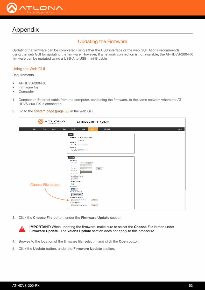
Appendix
Updating the Firmware
Updating the firmware can be completed using either the USB interface or the web GUI. Atlona recommendsusing the web GUI for updating the firmware. However, If a network connection is not available, the AT-HDVS-200-RX firmware can be updated using a USB-A to USB mini-B cable
Using the Web GUI
Requirements
• AT-HDVS-200-RX• Firmware file• Computer
1. Connect an Ethernet cable from the computer, containing the firmware, to the same network where the AT-HDVS-200-RX is connected.
2. Go to the System page (page 33) in the web GUI.
3. Click the Choose File button, under the Firmware Update section.
4. Browse to the location of the firmware file, select it, and click the Open button.
5. Click the Update button, under the Firmware Update section.
Choose File button
IMPORTANT: When updating the firmware, make sure to select the Choose File button under Firmware Update. The Valens Update section does not apply to this procedure.

AT-HDVS-200-RX 54
6. The following message box will be displayed.
7. Click the OK button to begin the firmware update process. Click the Cancel button to cancel the process.
8. After the firmware update process is complete, the Login screen will be displayed.
Appendix
Using USB
Requirements
• AT-HDVS-200-RX• Firmware file• Computer• USB-A to USB mini-B cable
1. Disconnect power from the AT-HDVS-200-RX.
2. Connect the USB-A to USB mini-B cable from the computer to the FW port on the AT-HDVS-200-RX.
PW
HDMIINPUT
DISPLAY
v
v
AT-HD-SC-500VOL
HDMI IN 1
HDMI IN 2 HDMI OUT
FW
LANDC 5V AUDIO OUT
RS-232RX
RL
TX
VGA IN AUDIO IN
1
2VGA
FW port

AT-HDVS-200-RX 55
Appendix
3. Press and hold the MENU key, on the front panel, while connecting power to the AT-HDVS-200-RX.
4. The USB UPDATE folder will be displayed. If this folder is not displayed, automatically, select the USB UPDATE drive from Windows Explorer.
7. Delete all files from the USB UPDATE drive, if any are present.
8. Drag-and-drop the firmware file to the drive.
9. After the file has been copied, disconnect the USB cable from both the computer and the AT-HDVS-200-RX.
10. Power-cycle the AT-HDVS-200-RX by disconnecting then reconnecting the power supply.
11. The firmware update process is complete.

AT-HDVS-200-RX 56
Feature Settings
Resolution Preferred Input Timing Output Format
1920x1080 720p60
Aspect ratio Full
Overscan Disabled
Audio Mute HDMI Audio L/R Audio Bass Treble
Off On On 0 0
Picture Brightness Contrast Saturation Hue Sharpness
64 64 6464 10
RS-232 port 1 Baud Rate Data Bits ParityStop Bits
9600 8 None 1
RS-232 port 2 Baud Rate Data Bits ParityStop Bits
115200 8 None 1
Zone Baud Rate Data Bits ParityStop Bits
115200 8 None 1
Login Username (default) Password (default)
root Atlona
Relay Control Relay 1 Relay 2
Follow Display Status Normally Closed (NC) Normally Open (NO)
Other Display HDCP In Auto Switch Mirror-V ASP Background
Compliant On Off Grey
Default Settings
The following tables list the factory-default settings for the AT-HDVS-200-RX.
Appendix

AT-HDVS-200-RX 57
Feature Settings
OSD Position Transparency Info Timer Menu Timer Info Display Menu Display Background
Left Top 12 10 (seconds) 20 (seconds) AutoAuto Grey
System IP Mode Static IP Address (default) Netmask Gateway Telnet Port Telnet Login Mode Telnet Timeout Broadcast
DHCP 192.168.1.254 255.255.255.0 192.168.1.1 23 Off 120 (seconds) On
Appendix

AT-HDVS-200-RX 58
Specifications
Video
Video [email protected]/24/25/29.97/30/50/59.94/60Hz, 1080i@50/59.94/60Hz, 720p@50/59.94/60Hz, 576p, 576i, 480p, 480i
VESA 1920×1200, 1680×1050, 1600×1200, 1600×900, 1440×900, 1400×1050, 1366×768, 1360×768, 1280×1024, 1280×800 1280×768, 1152×768, 1024×768, 800×600, 640×480
Color Space YUV, RGB
Chroma Subsampling 4:4:4, 4:2:2, 4:2:0*
Color Depth 8-bit, 10-bit, 12-bit
Audio
Analog PCM 2Ch (de-embedded)
HDMI OUT & HDBaseT IN PCM 2Ch, LPCM 5.1, LPCM 7.1, Dolby® Digital, DTS® 5.1, Dolby Digital Plus, Dolby TrueHD, DTS-HD Master Audio™
Sample Rate 32 kHz, 44.1 kHz, 48 kHz, 88.2 kHz, 96 kHz, 176.4 kHz, 192 kHz
Bit Rate 24-bit (max.)
Cable Feet Meters
CAT5e/6 @ 1080p 330 100
HDMI IN / OUT @ 1080p 30 10
Signal
Bandwidth 6.75 Gbps
CEC Yes
HDCP 1.4
Temperature Fahrenheit Celsius
Operating 32 to 122 0 to 50
Storage -4 to 140 -20 to 60
Humidity (RH) 20% to 90%, non-condensing
Appendix

AT-HDVS-200-RX 59
Power
Consumption 12 W30 W (when paired)
Supply Input: 100 - 240 V AC, 50/60 Hz Output: 48 V DC, 0.83 A
Dimensions Inches Millimeters
H x W x D 1.5 x 5 x 4.02 38 x 127 x 102
Weight Pounds Kilograms
Device 1.00 0.45
Certification
Unit CE, FCC
Appendix

AT-HDVS-200-RX 60
Index
AAspect ratio 28
setting 16Audio
analog 17connector 10enabling / disabling 17HDMI 17muting 52
BBackground color
setting 20Brightness 30, 31
adjusting 15
CCommands
Aspect 37Bass 37Blink 37Broadcast 38BRT 38CSpara 39CTRST 39HDBTRS232 40HDCPSet 40HDMIAUD 41help 41HUE 42HZoom 42Input 42IPAddUser 43IPCFG 43IPDelUser 43IPDHCP 44IPLogin 44IPPort 44IPStatic 45IPTimeout 45KitMode 45Mreset 46PictureRst 46PrefTimg 46RelayAct 47RelayAuto 47RS232para 48RS232zone 48SATRT 49SHARP 49System 49TREBLE 50Type 50
Version 50VidOutRes 51VOUT 51VOUTMute 52VZoom 52Zoom 52
Connectiondiagram 10instructions 10
Contentspackage 8
Contrast 30, 39adjusting 15
Customer support 3
DDefault setttings 56Description
front / rear panel 9DHCP 33, 44Down
button 13
FFCC statement 6Features 8Firmware
displaying 26updating
using the web GUI 53using USB 54
GGateway 34
HHDCP 19Hue 30, 42
adjusting 15
IInformation
displaying 20Input
selecting 14Installation 10IP address
default 45
MMenu
button 13main 13
Mutingaudio 52
OOperating notes 3OSD
background color 19position 18timer 18transparency 18
Outputvertically mirroring 20
Output volumeadjusting 51
Overscanadjusting 52enabling / disabling 16horizontal 16vertical 16
PPanel descriptions 9Password
setting 32Picture
reset 15Power
connector 11
RRelays 9, 11, 33Reset
factory-default 46to factory-default 22
Resolutioninput 14output 15, 51setting 27
RS-232connector 10
SSafety information 6Saturation 30
adjusting 15Sharpness 30, 49
adjusting 15

AT-HDVS-200-RX 61
Sourceinput 14
Specifications 58Static IP 33, 45Subnet mask 33
TTelnet
listening port 34login mode 34timeout 34
TMDSclock 21sync 21
UUp
button 13Users
adding 32, 43editing 32removing 32, 43
VVolume
adjusting 51
WWarranty 4Web GUI 23
Index

atlona.com • 408.962.0515 • 877.536.3976
© 2017 Atlona Inc. All rights reserved. “Atlona” and the Atlona logo are registered trademarks of Atlona Inc. All other brand names and trademarks or registered trademarks are the property of their respective owners. Pricing, specifications and availability subject to change without notice. Actual products, product images, and online product images may vary from images shown here.