Embed Size (px)
Citation preview

Protocol API
EtherCAT Master V4
V4.4.0
Hilscher Gesellschaft für Systemautomation mbH www.hilscher.com
DOC150601API05EN | Revision 5 | English | 2017-01 | Released | Public

Introduction 2/264
EtherCAT Master V4 | Protocol API DOC150601API05EN | Revision 5 | English | 2017-01 | Released | Public © Hilscher, 2015-2017
Table of contents
1 Introduction ............................................................................................................................................. 4 1.1 About this document ...................................................................................................................... 4 1.2 List of revisions............................................................................................................................... 4 1.3 Functional overview ....................................................................................................................... 5 1.4 System requirements ..................................................................................................................... 5 1.5 Intended audience .......................................................................................................................... 5 1.6 Specifications ................................................................................................................................. 6
1.6.1 Technical Data .................................................................................................................................. 6 1.7 Terms, abbreviations and definitions ............................................................................................. 8 1.8 References ..................................................................................................................................... 8 1.9 Legal notes ..................................................................................................................................... 9
1.9.1 Copyright ........................................................................................................................................... 9 1.9.2 Important notes ................................................................................................................................. 9 1.9.3 Exclusion of liability ......................................................................................................................... 10 1.9.4 Export .............................................................................................................................................. 10
2 Getting started / Configuration ........................................................................................................... 11 2.1 Configuration of the master .......................................................................................................... 11
2.1.1 Using the configuration tool SYCON.net ......................................................................................... 11 2.1.2 Detailed description of master parameters ...................................................................................... 12
3 Overview ................................................................................................................................................ 13 3.1 Task structure of the EtherCAT Master V4 stack ......................................................................... 13 3.2 Diagnosis ...................................................................................................................................... 14
3.2.1 DC diagnostics ................................................................................................................................ 14 3.2.2 Slave diagnostic information ............................................................................................................ 14 3.2.3 Diagnostic log .................................................................................................................................. 14 3.2.4 Bus scan .......................................................................................................................................... 15 3.2.5 LEDs controlled by EtherCAT Master .............................................................................................. 16
3.3 Process Data Reception .............................................................................................................. 18 3.4 Network topology recommendations ............................................................................................ 18
3.4.1 Store-and-forward switches not supported ...................................................................................... 18 4 The application interface ..................................................................................................................... 19
4.1 Addressing schemes used in EtherCAT Master .......................................................................... 19 4.1.1 Auto-increment address .................................................................................................................. 19 4.1.2 Fixed station address ...................................................................................................................... 19 4.1.3 Topology position ............................................................................................................................ 20 4.1.4 Device index .................................................................................................................................... 20
4.2 Distributed Clocks ........................................................................................................................ 21 4.3 Synchronization configuration ...................................................................................................... 21
4.3.1 Synchronization modes ................................................................................................................... 21 4.3.2 Packets ............................................................................................................................................ 24
4.4 State control ................................................................................................................................. 27 4.4.1 Architecture of master state control ................................................................................................. 27 4.4.2 Architecture of slave state control ................................................................................................... 28 4.4.3 Master state ..................................................................................................................................... 29 4.4.4 Master state (Legacy) ...................................................................................................................... 35 4.4.5 Slave state ....................................................................................................................................... 40
4.5 Status indications ......................................................................................................................... 45 4.5.1 Registration and deregistration of status indications ....................................................................... 45 4.5.2 Available indications ........................................................................................................................ 49
4.6 Diagnostic log ............................................................................................................................... 52 4.6.1 Entry format of diagnostic log .......................................................................................................... 52 4.6.2 Reading and clearing diagnostic log entries .................................................................................... 67 4.6.3 Diagnostic log indication handling ................................................................................................... 71
4.7 CoE services ................................................................................................................................ 79 4.7.1 Slave state accessibility ................................................................................................................... 79 4.7.2 SDO access .................................................................................................................................... 79 4.7.3 SDOINFO access ............................................................................................................................ 91 4.7.4 SDO access (Legacy) .................................................................................................................... 111 4.7.5 SDOINFO access (Legacy) ........................................................................................................... 116
4.8 FoE services............................................................................................................................... 126

Introduction 3/264
EtherCAT Master V4 | Protocol API DOC150601API05EN | Revision 5 | English | 2017-01 | Released | Public © Hilscher, 2015-2017
4.8.1 Slave state accessibility ................................................................................................................. 126 4.8.2 Fragmentation of write file (FoE) ................................................................................................... 126 4.8.3 Fragmentation of read IDN (SoE) .................................................................................................. 128 4.8.4 Packets .......................................................................................................................................... 130 4.8.5 FoE fragmentation flowcharts ........................................................................................................ 138
4.9 SoE services .............................................................................................................................. 140 4.9.1 Slave state accessibility ................................................................................................................. 140 4.9.2 Fragmentation of write IDN (SoE) ................................................................................................. 140 4.9.3 Fragmentation of read IDN (SoE) .................................................................................................. 142 4.9.4 Packets .......................................................................................................................................... 144 4.9.5 SoE fragmentation flowcharts ........................................................................................................ 152
4.10 Distributed Clocks diagnostics ................................................................................................... 154 4.10.1 Packets .......................................................................................................................................... 154 4.10.2 Legacy packets ............................................................................................................................. 164
4.11 Config readout ............................................................................................................................ 166 4.11.1 Get timing information ................................................................................................................... 166 4.11.2 Get WcState information ............................................................................................................... 168 4.11.3 Get cyclic command mapping ....................................................................................................... 172 4.11.4 Get cyclic slave mapping ............................................................................................................... 179
4.12 Retrieval of slave diagnostic information ................................................................................... 183 4.12.1 Provided lists ................................................................................................................................. 183 4.12.2 Limitations of configured slaves list ............................................................................................... 183 4.12.3 Limitations of active/faulted slaves list ........................................................................................... 183 4.12.4 Addressing scheme ....................................................................................................................... 183 4.12.5 Usage of slave diagnostic information packets .............................................................................. 184 4.12.6 Structure of per slave diagnostic data ........................................................................................... 185 4.12.7 Packets .......................................................................................................................................... 187
4.13 Retrieval of topology information................................................................................................ 196 4.13.1 Get topology information entries .................................................................................................... 196 4.13.2 Get topology information packet .................................................................................................... 197
4.14 ESC/SII access .......................................................................................................................... 199 4.14.1 ESC register access ...................................................................................................................... 199 4.14.2 ESC SII access ............................................................................................................................. 203 4.14.3 Legacy ESC SII access (ECM V3.X API) ...................................................................................... 207
4.15 ExtSync (since V4.3) .................................................................................................................. 214 4.15.1 Description of ExtSync functionality............................................................................................... 214 4.15.2 Get ExtSync information packet .................................................................................................... 215
4.16 Bus scan ..................................................................................................................................... 219 4.16.1 Packet parameter ulPortState.................................................................................................. 219 4.16.2 Generic bus scan .......................................................................................................................... 220 4.16.3 Legacy bus scan ........................................................................................................................... 225
5 Status/Error codes overview ............................................................................................................. 232 5.1 Error codes of the EtherCAT Master Task ................................................................................. 232
6 Appendix ............................................................................................................................................. 257 6.1 Accessing the protocol stack by programming the AP task’s queue ......................................... 257
6.1.1 Getting the receiver task handle of the process queue.................................................................. 257 6.2 Obtaining useful information about the communication channel ............................................... 257 6.3 Extended status ......................................................................................................................... 259 6.4 List of figures .............................................................................................................................. 260 6.5 List of tables ............................................................................................................................... 261 6.6 Contacts ..................................................................................................................................... 264

Introduction 4/264
EtherCAT Master V4 | Protocol API DOC150601API05EN | Revision 5 | English | 2017-01 | Released | Public © Hilscher, 2015-2017
1 Introduction 1.1 About this document This manual describes the application interface of the EtherCAT Master protocol stack. The aim of this manual is to support and guide you through the integration process of the given stack into your own application.
1.2 List of revisions Rev Date Name Revisions 3 2016-05-02 SB, RG EtherCAT Master V4.3.0
Review 4 2016-12-02 SB, RG EtherCAT Master V4.4.0
New (sub)sections: 3.3 Process Data Reception 3.4 Network topology recommendations 4.2 Distributed Clocks 4.11.3.3 Process data area type: DC SysTime 4.11.3.4 Process data area type: BRD ALStatus 4.11.3.5 Process data area type: BRD DcSysTimeDiff 4.11.3.6 Process data area type: WcState bits 4.11.3.7 Process data area type: ExtSync status 4.12.3 Limitations of active/faulted slaves list 4.12.7.4 Read CoE emergency messages The following (sub)sections have changed: 4.3.1.2 I/O sync mode 1 4.3.1.3 I/O sync mode 2 4.4.5 Slave state 4.7.2.4 Upload/read SDO 4.7.3.4 Get object list (OdList) 4.7.3.5 Get object description (ObjDesc) 4.7.3.6 Get entry description (EntryDesc) 4.12.6 Structure of per slave diagnostic data
5 2017-01-23 SB, HH EtherCAT Master V4.4.0 4.8 FoE services added.
Table 1: List of Revisions

Introduction 5/264
EtherCAT Master V4 | Protocol API DOC150601API05EN | Revision 5 | English | 2017-01 | Released | Public © Hilscher, 2015-2017
1.3 Functional overview The main functionality from application view is:
configure master and bus
exchange of cyclic data
slave diagnosis
1.4 System requirements This software package has following system requirements to its environment:
netX-Chip as CPU hardware platform
1.5 Intended audience This manual is suitable for software developers with the following background:
Knowledge of the programming language C
Knowledge of the use of the real-time operating system rcX
Knowledge of the Hilscher Task Layer Reference Model
Knowledge of the netX DPM Interface
Knowledge of the IEC 61158 Part 2-6 Type 12 specification documents
Introduction 6/264
EtherCAT Master V4 | Protocol API DOC150601API05EN | Revision 5 | English | 2017-01 | Released | Public © Hilscher, 2015-2017
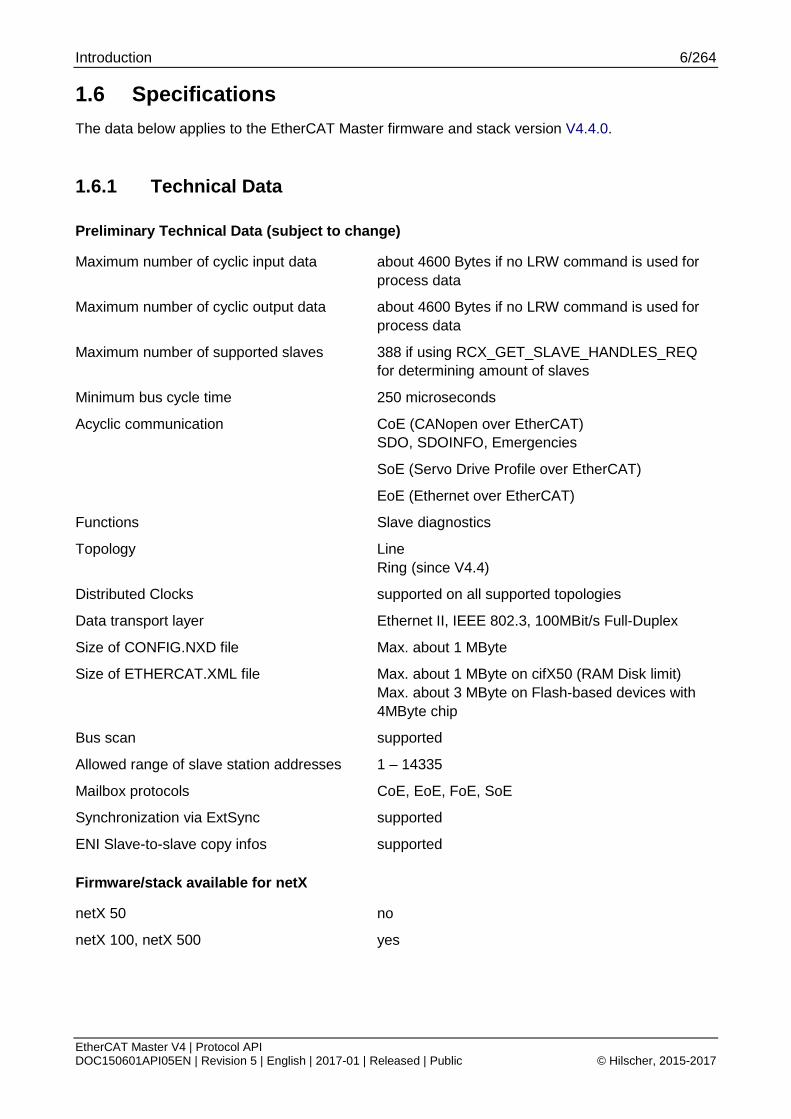
1.6 Specifications The data below applies to the EtherCAT Master firmware and stack version V4.4.0.
1.6.1 Technical Data
Preliminary Technical Data (subject to change)
Maximum number of cyclic input data about 4600 Bytes if no LRW command is used for process data
Maximum number of cyclic output data about 4600 Bytes if no LRW command is used for process data
Maximum number of supported slaves 388 if using RCX_GET_SLAVE_HANDLES_REQ for determining amount of slaves
Minimum bus cycle time 250 microseconds
Acyclic communication CoE (CANopen over EtherCAT) SDO, SDOINFO, Emergencies
SoE (Servo Drive Profile over EtherCAT)
EoE (Ethernet over EtherCAT)
Functions Slave diagnostics
Topology Line Ring (since V4.4)
Distributed Clocks supported on all supported topologies
Data transport layer Ethernet II, IEEE 802.3, 100MBit/s Full-Duplex
Size of CONFIG.NXD file Max. about 1 MByte
Size of ETHERCAT.XML file Max. about 1 MByte on cifX50 (RAM Disk limit) Max. about 3 MByte on Flash-based devices with 4MByte chip
Bus scan supported
Allowed range of slave station addresses 1 – 14335
Mailbox protocols CoE, EoE, FoE, SoE
Synchronization via ExtSync supported
ENI Slave-to-slave copy infos supported
Firmware/stack available for netX
netX 50 no
netX 100, netX 500 yes
Introduction 7/264
EtherCAT Master V4 | Protocol API DOC150601API05EN | Revision 5 | English | 2017-01 | Released | Public © Hilscher, 2015-2017
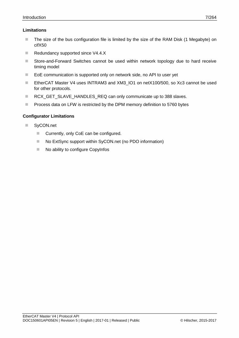
Limitations
The size of the bus configuration file is limited by the size of the RAM Disk (1 Megabyte) on cifX50
Redundancy supported since V4.4.X
Store-and-Forward Switches cannot be used within network topology due to hard receive timing model
EoE communication is supported only on network side, no API to user yet
EtherCAT Master V4 uses INTRAM3 and XM3_IO1 on netX100/500, so Xc3 cannot be used for other protocols.
RCX_GET_SLAVE_HANDLES_REQ can only communicate up to 388 slaves.
Process data on LFW is restricted by the DPM memory definition to 5760 bytes
Configurator Limitations
SyCON.net
Currently, only CoE can be configured.
No ExtSync support within SyCON.net (no PDO information)
No ability to configure CopyInfos

Introduction 8/264
EtherCAT Master V4 | Protocol API DOC150601API05EN | Revision 5 | English | 2017-01 | Released | Public © Hilscher, 2015-2017
1.7 Terms, abbreviations and definitions Term Description
AoE ADS over EtherCAT
AP (-task) Application (-task) on top of the stack CoE CANopen over EtherCAT DC Distributed Clocks DDF Data Description File DPM Dual Port Memory EEPROM Electronically Erasable Programmable Read-Only Memory ESC EtherCAT Slave Controller ESM EtherCAT State Machine ETG EtherCAT Technology Group EtherCAT Ethernet for Control and Automation Technology FoE File Access over EtherCAT HAL Hardware Abstraction Layer LFW Loadable firmware LOM Linkable object modules OD Object dictionary PDO Process Data Object (process data channel) SDO Service Data Object (representing an acyclic data channel) SHM Shared memory SII Slave Information Interface SoE Servo Drive Profile over EtherCAT XML Extended Markup Language
Table 2: Terms, Abbreviations and Definitions
All variables, parameters and data used in this manual have the LSB/MSB (“Intel”) data format. This corresponds to the convention of the Microsoft C Compiler.
1.8 References This document based on the following documents respectively specifications: 1 Hilscher Gesellschaft für Systemautomation mbH: Dual-Port Memory Interface Manual - netX based
products. Revision 12, English, 2011
2 Hilscher Gesellschaft für Systemautomation mbH: Driver Manual cifX Device Driver - Windows 2000/XP/Vista/7/CE V1.0.x.x. Revision 15, English, 2010
3 IEC 61158 Part 2-6 Type 12 specification documents
4 Hilscher Gesellschaft für Systemautomation mbH: Specification - netX IO Synchronization. Revision 6, English, 2010
5 ETG.1020 Protocol Enhancements
6 ETG.1500 Master Classes
7 ETG.2100 Network Information
8 Hilscher Gesellschaft für Systemautomation mbH: Network scan, Revision 5, English, 2017
Table 3: References

Introduction 9/264
EtherCAT Master V4 | Protocol API DOC150601API05EN | Revision 5 | English | 2017-01 | Released | Public © Hilscher, 2015-2017
1.9 Legal notes
1.9.1 Copyright © 2015-2016 Hilscher Gesellschaft für Systemautomation mbH
All rights reserved.
The images, photographs and texts in the accompanying material (user manual, accompanying texts, documentation, etc.) are protected by German and international copyright law as well as international trade and protection provisions. You are not authorized to duplicate these in whole or in part using technical or mechanical methods (printing, photocopying or other methods), to manipulate or transfer using electronic systems without prior written consent. You are not permitted to make changes to copyright notices, markings, trademarks or ownership declarations. The included diagrams do not take the patent situation into account. The company names and product descriptions included in this document may be trademarks or brands of the respective owners and may be trademarked or patented. Any form of further use requires the explicit consent of the respective rights owner.
1.9.2 Important notes The user manual, accompanying texts and the documentation were created for the use of the products by qualified experts, however, errors cannot be ruled out. For this reason, no guarantee can be made and neither juristic responsibility for erroneous information nor any liability can be assumed. Descriptions, accompanying texts and documentation included in the user manual do not present a guarantee nor any information about proper use as stipulated in the contract or a warranted feature. It cannot be ruled out that the user manual, the accompanying texts and the documentation do not correspond exactly to the described features, standards or other data of the delivered product. No warranty or guarantee regarding the correctness or accuracy of the information is assumed.
We reserve the right to change our products and their specification as well as related user manuals, accompanying texts and documentation at all times and without advance notice, without obligation to report the change. Changes will be included in future manuals and do not constitute any obligations. There is no entitlement to revisions of delivered documents. The manual delivered with the product applies.
Hilscher Gesellschaft für Systemautomation mbH is not liable under any circumstances for direct, indirect, incidental or follow-on damage or loss of earnings resulting from the use of the information contained in this publication.

Introduction 10/264
EtherCAT Master V4 | Protocol API DOC150601API05EN | Revision 5 | English | 2017-01 | Released | Public © Hilscher, 2015-2017
1.9.3 Exclusion of liability The software was produced and tested with utmost care by Hilscher Gesellschaft für Systemautomation mbH and is made available as is. No warranty can be assumed for the performance and flawlessness of the software for all usage conditions and cases and for the results produced when utilized by the user. Liability for any damages that may result from the use of the hardware or software or related documents, is limited to cases of intent or grossly negligent violation of significant contractual obligations. Indemnity claims for the violation of significant contractual obligations are limited to damages that are foreseeable and typical for this type of contract.
It is strictly prohibited to use the software in the following areas:
for military purposes or in weapon systems;
for the design, construction, maintenance or operation of nuclear facilities;
in air traffic control systems, air traffic or air traffic communication systems;
in life support systems;
in systems in which failures in the software could lead to personal injury or injuries leading to death.
We inform you that the software was not developed for use in dangerous environments requiring fail-proof control mechanisms. Use of the software in such an environment occurs at your own risk. No liability is assumed for damages or losses due to unauthorized use.
1.9.4 Export The delivered product (including the technical data) is subject to export or import laws as well as the associated regulations of different counters, in particular those of Germany and the USA. The software may not be exported to countries where this is prohibited by the United States Export Administration Act and its additional provisions. You are obligated to comply with the regulations at your personal responsibility. We wish to inform you that you may require permission from state authorities to export, re-export or import the product.

Getting started / Configuration 11/264
EtherCAT Master V4 | Protocol API DOC150601API05EN | Revision 5 | English | 2017-01 | Released | Public © Hilscher, 2015-2017
2 Getting started / Configuration This section explains some essential information you should know when starting to work with the EtherCAT Master V4 Protocol API.
2.1 Configuration of the master The master can be configured by using different means. This includes the following methods:
Configuration via SYCON.net
Timing parameters are specified by the user
Configuration via EtherCAT Network Information (ENI) files
Timing parameters are extracted from ENI in the specified locations.
The configuration via SYCON.net evaluates the ESI files provided for the slaves to be used and is therefore the easiest method.
2.1.1 Using the configuration tool SYCON.net The easiest way to configure the EtherCAT Master is using Hilscher’s configuration tool SYCON.net.
First, you need to create a project in SYCON.net. This is described in detail in the SYCON.net documentation.
Configure the bus and master parameters as described in the SYCON.net documentation.
After you completed your project, you can right-click on the icon of the EtherCAT Master and select "Connect".
You will see that the name of the EtherCAT Master will get a green background. Now right-click on the icon again and select "Download".
This will download the configuration files into the firmware. It is stored on a file system in a channel dependent directory ("PORT_0" for channel 0, "PORT_1” for channel 1, etc.).
After the download is finished, the driver requests the EtherCAT Master firmware to perform a Channel-Init. All current connections will be shut down by the firmware and a restart will be performed.
During this restart, the configuration that has been downloaded previously will be evaluated and used.

Getting started / Configuration 12/264
EtherCAT Master V4 | Protocol API DOC150601API05EN | Revision 5 | English | 2017-01 | Released | Public © Hilscher, 2015-2017
2.1.2 Detailed description of master parameters Both the bus and the master need to be configured. The accurate choice of the bus parameters is the foundation of correctly operating data exchange on the EtherCAT network.
The following table contains relevant information about the bus parameters (including the master’s parameters) for the EtherCAT Master V4 firmware such as a short explanation of the meaning of the parameter and ranges of allowed values:
Parameter Meaning Range of Value / Value Bus Cycle Time 2.1.2.1 Bus cycle time Process Data Output Size
2.1.2.2 Process data output size Minimum Value 0 Maximum Value 5760
Process Data Input Size
2.1.2.2 Process data output size Minimum Value 0 Maximum Value 5760
Table 4: Bus and Master Parameters, their Meanings and their Ranges of allowed Values
2.1.2.1 Bus cycle time
The bus cycle time specifies the actual bus cycle used.
2.1.2.2 Process data output size
This parameter determines the size of the area to be used for Process Data Output. It may not exceed the size of available space in DPM which is 5760 bytes.
2.1.2.3 Process data input size
This parameter determines the size of the area to be used for Process Data Input. It may not exceed the size of available space in DPM which is 5760 bytes.

Overview 13/264
EtherCAT Master V4 | Protocol API DOC150601API05EN | Revision 5 | English | 2017-01 | Released | Public © Hilscher, 2015-2017
3 Overview 3.1 Task structure of the EtherCAT Master V4 stack The illustration below displays the internal structure of the tasks which together represent the EtherCAT Master V4 Stack:
The dual-port memory is used for exchange of information, data and packets. Configuration and IO data will be transferred using this way.
The user application only accesses the task located in the highest layer namely the AP task which constitutes the application interface of the EtherCAT Master V4 stack.
The AP task represents the interface between the EtherCAT Master V4 protocol stack and the dual-port memory. It is responsible for:
Control of LEDs
Diagnosis
Packet routing
Update of the IO data
The triple buffer mechanism provides a consistent synchronous access procedure from both sides (DPM and AP task). The triple buffer technique ensures that the access will always affect the last written cell.

Overview 14/264
EtherCAT Master V4 | Protocol API DOC150601API05EN | Revision 5 | English | 2017-01 | Released | Public © Hilscher, 2015-2017
3.2 Diagnosis The following diagnostic capabilities are provided by the EtherCAT Master protocol stack:
Diagnostic log
Provides access to EtherCAT-specific diagnostic events
DC Diagnostics
Get Bus Info
Bus scan
Slave Diagnostic Information
3.2.1 DC diagnostics The EtherCAT Master provides access to recorded deviations when running with a DC configuration.
For details, see 4.10 Distributed Clocks diagnostics.
3.2.2 Slave diagnostic information The slave diagnostic information provides status information on what happened at each slave specifically. For details, see 4.12 Retrieval of slave diagnostic information.
3.2.3 Diagnostic log The EtherCAT Master protocol stack allows the application to be informed about various events such as:
Change of bus state
Failure of Init commands
Failure or warning in slave
Bus on/bus off
Channel init
DPM watchdog error
Change in topology
Bus scan
Internal error
For details about how to use the diagnostic log, see chapter 4.6 Diagnostic log.
Overview 15/264
EtherCAT Master V4 | Protocol API DOC150601API05EN | Revision 5 | English | 2017-01 | Released | Public © Hilscher, 2015-2017
3.2.4 Bus scan Bus scan provides the possibility to scan the network for available slaves. The bus scan request overrides the configured mode and switches the master internally to a similar operation mode as the unconfigured mode.
After the bus scan request has completed, the bus scan results can be read from all connected slaves.
For details on using bus scan, see chapter 4.16 Bus scan.

Overview 16/264
EtherCAT Master V4 | Protocol API DOC150601API05EN | Revision 5 | English | 2017-01 | Released | Public © Hilscher, 2015-2017
3.2.5 LEDs controlled by EtherCAT Master The following table describes how the LEDs are controlled by EtherCAT Master.
LED Color State Meaning RUN LED green
(off) Off INIT: The device is in state INIT.
(green) Blinking (2,5 Hz)
PRE-OPERATIONAL: The device is in PRE-OPERATIONAL state.
(green) Flickering (10 Hz)
The device is not configured.
(green) Single flash SAFE-OPERATIONAL: The device is in SAFE-OPERATIONAL state.
(green) On OPERATIONAL: The device is in OPERATIONAL state.
ERR LED red
(red) Single flash Bus Sync error threshold
(red) Double flash Internal Stop of the bus cycle
(red) Triple Flash DPM watchdog has expired.
(red) Quadruple Flash
No Master license present in the device.
(red) Blinking (2,5 Hz)
Error in the configuration database.
(red) Single Flickering
Channel Init was executed at the Master. Remarks: Transient error so can happen to be not visible at all.
(red) Double Flickering
Slave is missing. Unconfigured Slave No matching mandatory slave list No bus connected
(red) Flickering (10 Hz)
Boot-up was stopped due to an error.
(off) Off Master has no errors.
L/A LED green
(green) On Link: The device is linked to the Ethernet, but does not send/receive Ethernet frames.
(green) Flickering (load dependent)
Activity: The device is linked to the Ethernet and sends/receives Ethernet frames.
(off) Off The device has no link to the Ethernet.
Table 5: LED states for the EtherCAT Master

Overview 17/264
EtherCAT Master V4 | Protocol API DOC150601API05EN | Revision 5 | English | 2017-01 | Released | Public © Hilscher, 2015-2017
LED State Definition
On The indicator is constantly on.
Off The indicator is constantly off.
Single flash The indicator shows one short flash (200 ms) followed by a long “off“ phase (1,000 ms).
Double flash The indicator shows a sequence of two short flashes (each 200 ms), separated by a short off phase (200 ms). The sequence is finished by a long off phase (1,000 ms).
Triple Flash The indicator shows a sequence of three short flashes (each 200 ms), separated by a short off phase (200 ms). The sequence is finished by a long off phase (1,000 ms).
Quadruple Flash
The indicator shows a sequence of four short flashes (each 200 ms), separated by a short off phase (200 ms). The sequence is finished by a long off phase (1,000 ms).
Blinking (2,5 Hz)
The indicator turns on and off with a frequency of 2,5 Hz: “on” for 200 ms, followed by “off” for 200 ms.
Single Flickering
The indicator is switched on and off once: 'on' for 50 ms, followed by 'off' for 500 ms.
Double Flickering
The indicator is switched on and off and on once: 'on' / 'off' / 'on' each for approximately 50 ms, followed by 'off' for 500 ms.
Flickering (10 Hz)
The indicator turns on and off with a frequency of 10 Hz: 'on' for 50 ms, followed by 'off' for 50 ms.
Flickering (load dependent)
The indicator turns on and off with a frequency of approximately 10 Hz to indicate high Ethernet activity: on for approximately 50 ms, followed by off for 50 ms. The indicator turns on and off in irregular intervals to indicate low Ethernet activity.
Table 6: LED state definitions for the EtherCAT Master protocol

Overview 18/264
EtherCAT Master V4 | Protocol API DOC150601API05EN | Revision 5 | English | 2017-01 | Released | Public © Hilscher, 2015-2017
3.3 Process Data Reception The EtherCAT master uses a hard timing model to coordinate transmitting and receiving of I/O data.
The timing model is required to implement redundancy and distributed clocks being used together. The master has to combine received data from both ports to a single process data image.
If such a frame arrives outside of the receive end time point, the frame is considered as not being received. If it carries the actual input process data, the frame is considered as not being received and the fall-back behavior is active. This is done by default in order to clear the related input process data area.
The EtherCAT master will start up such a network since acyclic commands are not processed through the cyclic receive handler.
3.4 Network topology recommendations
3.4.1 Store-and-forward switches not supported Do not use store-and-forward switches on EtherCAT networks in production usage at all. Those switches cause large additional delays within the network.
Depending on the configuration such a store and forward device adds easily up to 50-100 µs of additional cable delay.
The EtherCAT master will start up such a network through the cyclic receive handler since acyclic commands are not processed. However, the input process image will not show such delayed data.
The receive timing calculation cannot know about network components that are not visible as EtherCAT slaves.
3.4.1.1 DC disturbance
Such devices like store-and-forward switches introduce larger delays and jitter due to their internal functioning. Therefore, setups for distributed clocks should not integrate such devices into the topology.

The application interface 19/264
EtherCAT Master V4 | Protocol API DOC150601API05EN | Revision 5 | English | 2017-01 | Released | Public © Hilscher, 2015-2017
4 The application interface 4.1 Addressing schemes used in EtherCAT Master
4.1.1 Auto-increment address The auto-increment addressing is the addressing method on the EtherCAT bus associated with topology dependent addressing.
The following table illustrates the relation between the auto-Increment address and the position in topology:
Auto-Increment Address Position in topology 0x0000 First slave in topology (position 1) 0xFFFF Second slave in topology
0xFFFE Third slave in topology
0x0001-n Slave in topology at position n
Table 7: Auto-increment address related to topology position
For accessing acyclic services during generic bus scan, the master uses a derived scheme called topology position which is defined as following wrap-around calculation:
uint16_t usTopologyPosition = 0x0001 – usAutoIncAddress;
For details about topology position, see 4.1.3 Topology position.
This addressing scheme is used in the following services:
4.14.3 Legacy ESC SII access (ECM V3.X API)
4.16.3 Legacy bus scan
4.1.2 Fixed station address The fixed station address is used as long as a configuration is active in the master and bus scan is not active. The fixed station address is defined by configuration and is not topology dependent.
This addressing scheme is used in the following services:
4.4.5 Slave state
4.6 Diagnostic log
4.7 CoE services
4.9 SoE services
4.14.1 ESC register access
4.14.2 ESC SII access
4.14.3 Legacy ESC SII access (ECM V3.X API)

The application interface 20/264
EtherCAT Master V4 | Protocol API DOC150601API05EN | Revision 5 | English | 2017-01 | Released | Public © Hilscher, 2015-2017
4.1.3 Topology position The Topology position addressing scheme is used to simplify internal structure based on the supported station address numbering allowed.
Following table illustrates topology Position and position in topology:
Topology Position
Position in topology
0x0001 First slave in topology (position 1) 0x0002 Second slave in topology
0x0003 Third slave in topology
0x0000+n Slave in topology at position n
Table 8: Topology position scheme related to topology position on bus
For calculating auto-increment address from the topology position the following wrap-around calculation is used:
uint16_t usAutoIncAddress = 0x0001 – usTopology Position;
For details about auto-increment Address, see 4.1.1 Auto-increment address.
This addressing scheme is used in the following services when generic bus scan is active:
4.7 CoE services
4.9 SoE services
4.14.1 ESC register access
4.14.2 ESC SII access
4.14.3 Legacy ESC SII access (ECM V3.X API)
If fixed addressing using
4.16.2 Generic bus scan
4.1.4 Device index The device index is solely derived from configuration load order. It does not resemble any kind of position based addressing.
This addressing scheme is used in the following services:
4.12.7.3 Get slave connection information service

The application interface 21/264
EtherCAT Master V4 | Protocol API DOC150601API05EN | Revision 5 | English | 2017-01 | Released | Public © Hilscher, 2015-2017
4.2 Distributed Clocks The EtherCAT master always uses the first available DC supporting slave as DC reference clock.
The reasons for this are mainly:
Lower jitter compared to PHY jitter
Broadcast Read on DcSysTimeDiff register possible
4.3 Synchronization configuration The synchronization configuration applies only to LFW/SHM. Its purpose is configuring the DPM handling accordingly. This allows applications to run synchronously to the bus cycle if needed.
4.3.1 Synchronization modes
4.3.1.1 Free-run
In Free-Run Mode, the application can exchange process data at any time. However, the handshake bit handling is not related to the bus cycle i.e. the toggle back by netX happens at any time. The application cannot determine the bus cycle reference from the handshake bits in this mode.

The application interface 22/264
EtherCAT Master V4 | Protocol API DOC150601API05EN | Revision 5 | English | 2017-01 | Released | Public © Hilscher, 2015-2017
4.3.1.2 I/O sync mode 1
The I/O Sync Mode 1 allows determining the bus cycle reference from the input handshake bit. However, the input and output process data exchanges are not handled at the same time within the stack. Therefore, the application has to obey particular rules within this mode.
The inputs are only provided to the application every bus cycle when proper handshaking is done. If the application does not toggle the input data handshake to the netX, the master will not provide new inputs until the application has given the handshake to the netX. In the error case, the master is incrementing the input update error PDInCnt.
The output exchange is accepted at any time but the recommendation is to loosely couple the output exchange via the application cycle. If the application does not provide output data to be transmitted in time, the master will send the previously exchanged output process data.
The latency of I/O sync mode 1 is one cycle since when the application receive data from the bus and the time its output data is passed on the bus is one cycle later. The available time for the application processing data is slightly shorter than I/O sync mode 2.
Frame Transmit
Frame ReceiveD U
DCBaseTimeBusCycle Start SYNC0
SYNC0ShiftTime
DCBaseTimeShift
RxEndTime
ApplicationApplication
O I
Activation of outputs at SYNC0
Figure 1: I/O sync mode 1 Timing Diagram

The application interface 23/264
EtherCAT Master V4 | Protocol API DOC150601API05EN | Revision 5 | English | 2017-01 | Released | Public © Hilscher, 2015-2017
4.3.1.3 I/O sync mode 2
The I/O Sync Mode 2 allows determining the bus cycle reference from the input handshake bit. However, the input and output process data exchanges are not handled at the same time within the stack. Therefore, the application has to obey particular rules within this mode.
The inputs are only provided to the application every bus cycle when proper handshaking is done. If the application does not toggle the input data handshake to the netX, the master will not provide new inputs until the application has given the handshake to the netX. In case of an error, the master is incrementing the input update error PDInCnt.
The output exchange is accepted at any time but the recommendation is to loosely couple the output exchange via the application cycle. If the application does not provide output data to be transmitted in time, the master will send the previously exchanged output process data.
The latency of I/O sync mode 2 is two cycles since when the application receive data from the bus and the time its output data is passed on the bus is two cycles later.
Frame Transmit
Frame ReceiveD U
DCBaseTimeBusCycle Start SYNC0
SYNC0ShiftTime
DCBaseTimeShift
RxEndTime
Application
O I
Activation of outputs at SYNC0 Fra
D
BusCycle St
F
Application
Figure 2: I/O sync mode 2 timing diagram

The application interface 24/264
EtherCAT Master V4 | Protocol API DOC150601API05EN | Revision 5 | English | 2017-01 | Released | Public © Hilscher, 2015-2017
4.3.2 Packets
4.3.2.1 Set handshake configuration
This packet has to be used for reconfiguring the synchronization modes provided through DPM.
Packet structure reference typedef struct RCX_SET_HANDSHAKE_CONFIG_REQ_DATA_Ttag { TLR_UINT8 bPDInHskMode; TLR_UINT8 bPDInSource; TLR_UINT16 usPDInErrorTh; TLR_UINT8 bPDOutHskMode; TLR_UINT8 bPDOutSource; TLR_UINT16 usPDOutErrorTh; TLR_UINT8 bSyncHskMode; TLR_UINT8 bSyncSource; TLR_UINT16 usSyncErrorTh; TLR_UINT32 aulReserved[2]; } RCX_SET_HANDSHAKE_CONFIG_REQ_DATA_T; typedef struct RCX_SET_HANDSHAKE_CONFIG_REQ_Ttag { TLR_PACKET_HEADER_T tHead; RCX_SET_HANDSHAKE_CONFIG_REQ_DATA_T tData; } RCX_SET_HANDSHAKE_CONFIG_REQ_T;

The application interface 25/264
EtherCAT Master V4 | Protocol API DOC150601API05EN | Revision 5 | English | 2017-01 | Released | Public © Hilscher, 2015-2017
Packet description
Structure RCX_SET_HANDSHAKE_CONFIG_REQ_T Type: Request
Variable Type Value / range
Description
tHead - Structure TLR_PACKET_HEADER_T
ulDest UINT32 Destination queue-handle ulSrc UINT32 Source queue-handle ulDestId UINT32 Destination End Point Identifier, specifying the final receiver of the packet
within the Destination Process. Set to 0 for the Initialization Packet ulSrcId UINT32 Source End Point Identifier, specifying the origin of the packet inside the
Source Process ulLen UINT32 20 Packet Data Length in bytes ulId UINT32 0 ... 232-1 Packet Identification as unique number generated by the Source Process
of the Packet ulSta UINT32 See section Status/Error codes overview ulCmd UINT32 0x2F34 RCX_SET_HANDSHAKE_CONFIG_REQ - Command
ulExt UINT32 0 Extension not in use, set to zero for compatibility reasons ulRout UINT32 x Routing, do not touch
tData – Structure RCX_SET_HANDSHAKE_CONFIG_REQ_DATA_T
bPDInHskMode UINT8 Input Process Data Handshake Mode bPDInSource UINT8 Input Process Data Trigger Source usPDInErrorTh UINT16 0 Threshold for input process data handshake handling error. bPDOutHskMode UINT8 Output Process Data Handshake Mode bPDOutSource UINT8 Output Process Data Trigger Source usPDOutErrorTh UINT16 0 Threshold for output process data handshake handling error bSyncHskMode UINT8 0 Synchronization Handshake Mode bSyncSource UINT8 0 Synchronization Source usSyncErrorTh UINT16 0 Threshold for synchronization handshake handling error
Table 9: RCX_SET_HANDSHAKE_CONFIG_REQ – Set handshake configuration request
Available modes
bPDInHskMode bPDInSource bPDOutHskMode bPDOutSource Description
0/4 0 0/4 0 Free-Run
5 0 4 0 I/O Sync Mode 1
6 0 4 0 I/O Sync Mode 2
For mode descriptions, see 4.3.1 Synchronization modes.

The application interface 26/264
EtherCAT Master V4 | Protocol API DOC150601API05EN | Revision 5 | English | 2017-01 | Released | Public © Hilscher, 2015-2017
Packet structure reference typedef struct RCX_SET_HANDSHAKE_CONFIG_CNF_Ttag { TLR_PACKET_HEADER_T tHead; } RCX_SET_HANDSHAKE_CONFIG_CNF_T;
Packet description
Structure RCX_SET_HANDSHAKE_CONFIG_CNF_T Type: Confirmation
Variable Type Value / range Description tHead - Structure TLR_PACKET_HEADER_T
ulDest UINT32 Destination queue-handle ulSrc UINT32 Source queue-handle ulDestId UINT32 Destination End Point Identifier, specifying the final receiver of the
packet within the Destination Process. Set to 0 for the Initialization Packet
ulSrcId UINT32 Source End Point Identifier, specifying the origin of the packet inside the Source Process
ulLen UINT32 0 Packet Data Length in bytes ulId UINT32 0 ... 232-1 Packet Identification as unique number generated by the Source
Process of the Packet ulSta UINT32 See section Status/Error codes overview ulCmd UINT32 0x2F35 RCX_SET_HANDSHAKE_CONFIG_CNF - Command
ulExt UINT32 0 Extension not in use, set to zero for compatibility reasons ulRout UINT32 x Routing, do not touch
Table 10: RCX_SET_HANDSHAKE_CONFIG_CNF – Set handshake configuration confirmation

The application interface 27/264
EtherCAT Master V4 | Protocol API DOC150601API05EN | Revision 5 | English | 2017-01 | Released | Public © Hilscher, 2015-2017
4.4 State control
4.4.1 Architecture of master state control The master implements a separation between target state setting and changing the current state. Therefore, the packets for setting the target state will only set the new state to reach. The confirmations return immediately. So, these do not indicate completion of the state change at all.
In order to determine completion and current network status, the following services have to be used:
4.4.3.2 Get current master state
(Polling based, application actively requests for current status)
4.5 Status indications
(Event based, master signals indications to the application)
Bus off and setting the target state
The new target state can be set when the master is set to Bus Off. The request will be returned with the error code ECM_INFO_EMC_BUS_IS_OFF (0x40CD0017). However, the action of the packet is still executed.
Error codes related to successful operation
TLR_S_OK (0x00000000)
The master has accepted the new target phase and will proceed to it.
ECM_INFO_EMC_BUS_IS_OFF (0x40CD0017)
The master has accepted the new target state. However, Bus Off locks it to inactive state.
Indications and setting the target state
When the state indication indicates the same phase as the last issued Set Target State request, the phase change has been completed successfully.
When the state indication is received with ulStopReason unequal 0, the phase change has been aborted due to an error during phase change.
Note: The diagnostic log can provide additional detail on the reason. For details about how to use the diagnostic log, see chapter 4.6 Diagnostic log.

The application interface 28/264
EtherCAT Master V4 | Protocol API DOC150601API05EN | Revision 5 | English | 2017-01 | Released | Public © Hilscher, 2015-2017
4.4.2 Architecture of slave state control When the master state control is not active, the slaves can be set to specific state e.g. BOOT.
The master implements a separation between target state setting and changing the current state. Therefore, the packets for setting the target state will only set the new state to reach. The confirmations return immediately. So, these do not indicate completion of the state change at all.
In order to determine completion and current slave status, the following services have to be used:
4.4.5.2 Get current slave state
(Polling based, application actively requests for current status)
Bus off
During Bus off, no state setting of slaves is allowed.
Error codes related to successful operation
TLR_S_OK (0x00000000)
The master has accepted the new target phase and will proceed to it.
Getting current state and setting the target state
When the Get Slave Current State confirmation indicates the same phase as the last issued Set Slave Target State request, the phase change has been completed successfully.
When the Get Slave Current State confirmation is received with ulActiveError unequal 0, the phase change has been aborted due to an error during phase change.
Note: The diagnostic log can provide additional detail on the reason. For details about how to use the diagnostic log, see chapter 4.6 Diagnostic log.

The application interface 29/264
EtherCAT Master V4 | Protocol API DOC150601API05EN | Revision 5 | English | 2017-01 | Released | Public © Hilscher, 2015-2017
4.4.3 Master state
4.4.3.1 Set master target state
The service is used for requesting a new master target state specified in bTargetState.
If the packet has been returned with ulSta equal to TLR_S_OK, the master will change the bus status to the newly requested target state.
For details on how to determine the current network status, see 4.4.1 Architecture of master state control.
Packet structure reference typedef struct ECM_IF_SET_MASTER_TARGET_STATE_REQ_DATA_Ttag { uint8_t bTargetState; } ECM_IF_SET_MASTER_TARGET_STATE_REQ_DATA_T; typedef struct ECM_IF_SET_MASTER_TARGET_STATE_REQ_Ttag { TLR_PACKET_HEADER_T tHead; ECM_IF_SET_MASTER_TARGET_STATE_REQ_DATA_T tData; } ECM_IF_SET_MASTER_TARGET_STATE_REQ_T;
Packet description
Structure ECM_IF_SET_MASTER_TARGET_STATE_REQ_T Type: Request
Variable Type Value / range Description tHead - Structure TLR_PACKET_HEADER_T
ulDest UINT32 Destination queue-handle ulSrc UINT32 Source queue-handle ulDestId UINT32 Destination End Point Identifier, specifying the final receiver of the
packet within the Destination Process. Set to 0 for the Initialization Packet
ulSrcId UINT32 Source End Point Identifier, specifying the origin of the packet inside the Source Process
ulLen UINT32 1 Packet Data Length in bytes ulId UINT32 0 ... 232-1 Packet Identification as unique number generated by the Source
Process of the Packet ulSta UINT32 See section Status/Error codes overview ulCmd UINT32 0x9E00 ECM_IF_CMD_SET_MASTER_TARGET_STATE_REQ - Command
ulExt UINT32 0 Extension not in use, set to zero for compatibility reasons ulRout UINT32 x Routing, do not touch
tData – Structure ECM_IF_SET_MASTER_TARGET_STATE_REQ_DATA_T bTargetState UINT8 1,2,4,8 Target state. See Table 12: Possible values of bTargetState
Table 11: ECM_IF_CMD_SET_MASTER_TARGET_STATE_REQ –Set master target state request

The application interface 30/264
EtherCAT Master V4 | Protocol API DOC150601API05EN | Revision 5 | English | 2017-01 | Released | Public © Hilscher, 2015-2017
Defined values for bTargetState
Value Definition / description 0x01 ECM_IF_STATE_INIT
Master is requested to be in state INIT 0x02 ECM_IF_STATE_PREOP
Master is requested to be in state PREOP 0x04 ECM_IF_STATE_SAFEOP
Master is requested to be in state SAFEOP 0x08 ECM_IF_STATE_OP
Master is requested to be in state OP
Table 12: Possible values of bTargetState
Packet structure reference typedef struct ECM_IF_SET_MASTER_TARGET_STATE_CNF_DATA_Ttag { uint8_t bTargetState; } ECM_IF_SET_MASTER_TARGET_STATE_CNF_DATA_T typedef struct ECM_IF_SET_MASTER_TARGET_STATE_CNF_Ttag { TLR_PACKET_HEADER_T tHead; ECM_IF_SET_MASTER_TARGET_STATE_CNF_DATA_T tData; } ECM_IF_SET_MASTER_TARGET_STATE_CNF_T;
Packet description
Structure ECM_IF_SET_MASTER_TARGET_STATE_CNF_T Type: Confirmation
Variable Type Value / range Description tHead - Structure TLR_PACKET_HEADER_T ulDest UINT32 Destination queue handle, unchanged ulSrc UINT32 Source queue handle, unchanged ulDestId UINT32 Destination End Point Identifier, specifying the final receiver of the packet
within the Destination Process. Set to 0 for the Initialization Packet ulSrcId UINT32 Source End Point Identifier, specifying the origin of the packet inside the
Source Process ulLen UINT32 1 Packet Data Length in bytes ulId UINT32 0 ... 232-1 Packet Identification, unchanged ulSta UINT32 See section Status/Error codes overview ulCmd UINT32 0x9E01 ECM_IF_CMD_SET_MASTER_TARGET_STATE_CNF – Command
ulExt UINT32 0 Extension, reserved ulRout UINT32 x Routing information, do not change
tData – Structure ECM_IF_SET_MASTER_TARGET_STATE_CNF_DATA_T bTargetState UINT8 1,2,4,8 Same value as specified in request for target state
Table 13: ECM_IF_CMD_SET_MASTER_TARGET_STATE_CNF – Set master target state confirmation
The application interface 31/264
EtherCAT Master V4 | Protocol API DOC150601API05EN | Revision 5 | English | 2017-01 | Released | Public © Hilscher, 2015-2017
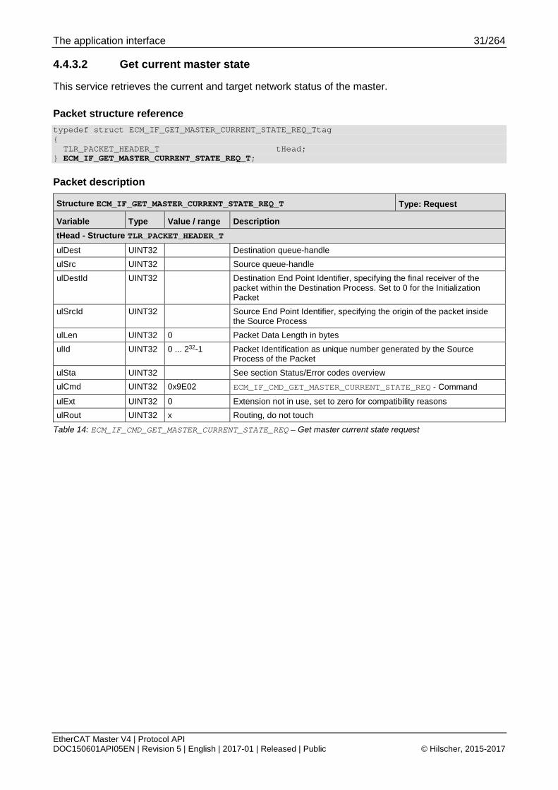
4.4.3.2 Get current master state
This service retrieves the current and target network status of the master.
Packet structure reference typedef struct ECM_IF_GET_MASTER_CURRENT_STATE_REQ_Ttag { TLR_PACKET_HEADER_T tHead; } ECM_IF_GET_MASTER_CURRENT_STATE_REQ_T;
Packet description
Structure ECM_IF_GET_MASTER_CURRENT_STATE_REQ_T Type: Request
Variable Type Value / range Description tHead - Structure TLR_PACKET_HEADER_T ulDest UINT32 Destination queue-handle ulSrc UINT32 Source queue-handle ulDestId UINT32 Destination End Point Identifier, specifying the final receiver of the
packet within the Destination Process. Set to 0 for the Initialization Packet
ulSrcId UINT32 Source End Point Identifier, specifying the origin of the packet inside the Source Process
ulLen UINT32 0 Packet Data Length in bytes ulId UINT32 0 ... 232-1 Packet Identification as unique number generated by the Source
Process of the Packet ulSta UINT32 See section Status/Error codes overview ulCmd UINT32 0x9E02 ECM_IF_CMD_GET_MASTER_CURRENT_STATE_REQ - Command
ulExt UINT32 0 Extension not in use, set to zero for compatibility reasons ulRout UINT32 x Routing, do not touch
Table 14: ECM_IF_CMD_GET_MASTER_CURRENT_STATE_REQ – Get master current state request
The application interface 32/264
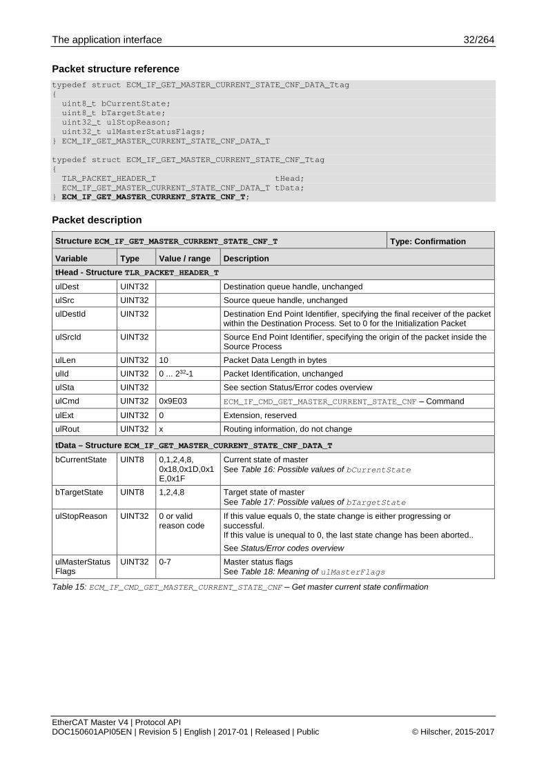
EtherCAT Master V4 | Protocol API DOC150601API05EN | Revision 5 | English | 2017-01 | Released | Public © Hilscher, 2015-2017
Packet structure reference typedef struct ECM_IF_GET_MASTER_CURRENT_STATE_CNF_DATA_Ttag { uint8_t bCurrentState; uint8_t bTargetState; uint32_t ulStopReason; uint32_t ulMasterStatusFlags; } ECM_IF_GET_MASTER_CURRENT_STATE_CNF_DATA_T typedef struct ECM_IF_GET_MASTER_CURRENT_STATE_CNF_Ttag { TLR_PACKET_HEADER_T tHead; ECM_IF_GET_MASTER_CURRENT_STATE_CNF_DATA_T tData; } ECM_IF_GET_MASTER_CURRENT_STATE_CNF_T;
Packet description
Structure ECM_IF_GET_MASTER_CURRENT_STATE_CNF_T Type: Confirmation
Variable Type Value / range Description tHead - Structure TLR_PACKET_HEADER_T ulDest UINT32 Destination queue handle, unchanged ulSrc UINT32 Source queue handle, unchanged ulDestId UINT32 Destination End Point Identifier, specifying the final receiver of the packet
within the Destination Process. Set to 0 for the Initialization Packet ulSrcId UINT32 Source End Point Identifier, specifying the origin of the packet inside the
Source Process ulLen UINT32 10 Packet Data Length in bytes ulId UINT32 0 ... 232-1 Packet Identification, unchanged ulSta UINT32 See section Status/Error codes overview ulCmd UINT32 0x9E03 ECM_IF_CMD_GET_MASTER_CURRENT_STATE_CNF – Command
ulExt UINT32 0 Extension, reserved ulRout UINT32 x Routing information, do not change
tData – Structure ECM_IF_GET_MASTER_CURRENT_STATE_CNF_DATA_T bCurrentState UINT8 0,1,2,4,8,
0x18,0x1D,0x1E,0x1F
Current state of master See Table 16: Possible values of bCurrentState
bTargetState UINT8 1,2,4,8 Target state of master See Table 17: Possible values of bTargetState
ulStopReason UINT32 0 or valid reason code
If this value equals 0, the state change is either progressing or successful. If this value is unequal to 0, the last state change has been aborted.. See Status/Error codes overview
ulMasterStatusFlags
UINT32 0-7 Master status flags See Table 18: Meaning of ulMasterFlags
Table 15: ECM_IF_CMD_GET_MASTER_CURRENT_STATE_CNF – Get master current state confirmation

The application interface 33/264
EtherCAT Master V4 | Protocol API DOC150601API05EN | Revision 5 | English | 2017-01 | Released | Public © Hilscher, 2015-2017
Defined values for bCurrentState
Value Definition / description 0x00 ECM_IF_STATE_BUSOFF
Master is in state Bus off 0x01 ECM_IF_STATE_INIT
Master is in state INIT 0x02 ECM_IF_STATE_PREOP
Master is in state PREOP 0x04 ECM_IF_STATE_SAFEOP
Master is in state SAFEOP 0x08 ECM_IF_STATE_OP
Master is in state OP 0x18 ECM_IF_STATE_LEAVE_OP
Master is leaving OP state. This state is signaled when master begins processing a state change away from OP
0x1D ECM_IF_STATE_BUSSCAN_COMPLETE_NO_PREOP
Legacy bus scan completed 0x1E ECM_IF_STATE_BUSSCAN
Bus scan in progress 0x1F ECM_IF_STATE_BUSSCAN_COMPLETE
Bus scan is completed and PREOP is reached with all slaves.
Table 16: Possible values of bCurrentState
Defined values for bTargetState
Value Definition / description 0x01 ECM_IF_STATE_INIT
Master is requested to be in state INIT 0x02 ECM_IF_STATE_PREOP
Master is requested to be in state PREOP 0x04 ECM_IF_STATE_SAFEOP
Master is requested to be in state SAFEOP 0x08 ECM_IF_STATE_OP
Master is requested to be in state OP
Table 17: Possible values of bTargetState

The application interface 34/264
EtherCAT Master V4 | Protocol API DOC150601API05EN | Revision 5 | English | 2017-01 | Released | Public © Hilscher, 2015-2017
Bit mask for ulMasterFlags
Bit No. Definition / description
31-3 RESERVED
Reserved, set to 0.
2 MSK_ECM_IF_MASTER_STATUS_FLAGS_AT_LEAST_ONE_MANDATORY_SLAVE_NOT_IN_OP
If this bit is set, at least one mandatory slave is not in OP when master is in OP. But, the slave is still connected.
1 MSK_ECM_IF_MASTER_STATUS_FLAGS_DC_XRMW_STOPPED
If this bit is set, the DC handling stopped sending ARMW/FRMW telegrams. The DC Slaves are not synchronizing their sys time in that case.
0 MSK_ECM_IF_MASTER_STATUS_FLAGS_AT_LEAST_ONE_MANDATORY_SLAVE_LOST
If this bit is set, at least one mandatory slave is not connected to master anymore.
Table 18: Meaning of ulMasterFlags

The application interface 35/264
EtherCAT Master V4 | Protocol API DOC150601API05EN | Revision 5 | English | 2017-01 | Released | Public © Hilscher, 2015-2017
4.4.4 Master state (Legacy) The legacy packets are available for applications which have been developed for ECM V3.X.
4.4.4.1 Set target state (Legacy)
This service is used for requesting a target state specified in usNewEcState.
If the packet has been returned with ulSta equal to TLR_S_OK, the master will change the bus status to the newly requested target state.
For details on how to determine the current network status, see 4.4.1 Architecture of master state control.
Packet structure reference typedef struct ETHERCAT_MASTER_PACKET_SET_ECSTATE_REQ_DATA_Ttag { uint16_t usNewEcState; } ETHERCAT_MASTER_PACKET_SET_ECSTATE_REQ_DATA_T; typedef struct ETHERCAT_MASTER_PACKET_SET_ECSTATE_REQ_Ttag { TLR_PACKET_HEADER_T tHead; ETHERCAT_MASTER_PACKET_SET_ECSTATE_REQ_DATA_T tData; } ETHERCAT_MASTER_PACKET_SET_ECSTATE_REQ_T;
Packet description
Structure ETHERCAT_MASTER_PACKET_SET_ECSTATE_REQ_T Type: Request
Variable Type Value / range Description tHead - Structure TLR_PACKET_HEADER_T ulDest UINT32 Destination queue-handle ulSrc UINT32 Source queue-handle ulDestId UINT32 Destination End Point Identifier, specifying the final receiver of the
packet within the Destination Process. Set to 0 for the Initialization Packet
ulSrcId UINT32 Source End Point Identifier, specifying the origin of the packet inside the Source Process
ulLen UINT32 2 Packet Data Length in bytes ulId UINT32 0 ... 232-1 Packet Identification as unique number generated by the Source
Process of the Packet ulSta UINT32 See section Status/Error codes overview ulCmd UINT32 0x650048 ETHERCAT_MASTER_CMD_SET_ECSTATE_REQ - Command
ulExt UINT32 0 Extension not in use, set to zero for compatibility reasons ulRout UINT32 x Routing, do not touch
tData – Structure ETHERCAT_MASTER_PACKET_SET_ECSTATE_REQ_DATA_T
usNewEcState UINT16 1,2,4,8 Target state. See Table 20: Possible values of usNewEcState
Table 19: ETHERCAT_MASTER_CMD_SET_ECSTATE_REQ – Set master target state request (Legacy)

The application interface 36/264
EtherCAT Master V4 | Protocol API DOC150601API05EN | Revision 5 | English | 2017-01 | Released | Public © Hilscher, 2015-2017
Defined values for usNewEcState
Value Definition / description 0x01 ECM_IF_STATE_INIT / ETHERCAT_MASTER_BUSSTATE_INIT
Master is requested to be in state INIT 0x02 ECM_IF_STATE_PREOP / ETHERCAT_MASTER_BUSSTATE_PREOP
Master is requested to be in state PREOP 0x04 ECM_IF_STATE_SAFEOP / ETHERCAT_MASTER_BUSSTATE_SAFEOP
Master is requested to be in state SAFEOP 0x08 ECM_IF_STATE_OP / ETHERCAT_MASTER_BUSSTATE_OP
Master is requested to be in state OP
Table 20: Possible values of usNewEcState
Packet structure reference typedef struct ETHERCAT_MASTER_PACKET_SET_ECSTATE_CNF_Ttag { TLR_PACKET_HEADER_T tHead; } ETHERCAT_MASTER_PACKET_SET_ECSTATE_CNF_T;
Packet description
Structure ETHERCAT_MASTER_PACKET_SET_ECSTATE_CNF_T Type: Confirmation
Variable Type Value / range Description tHead - Structure TLR_PACKET_HEADER_T ulDest UINT32 Destination queue handle, unchanged ulSrc UINT32 Source queue handle, unchanged ulDestId UINT32 Destination End Point Identifier, specifying the final receiver of the packet
within the Destination Process. Set to 0 for the Initialization Packet ulSrcId UINT32 Source End Point Identifier, specifying the origin of the packet inside the
Source Process ulLen UINT32 0 Packet Data Length in bytes ulId UINT32 0 ... 232-1 Packet Identification, unchanged ulSta UINT32 See section Status/Error codes overview ulCmd UINT32 0x650049 ETHERCAT_MASTER_CMD_SET_ECSTATE_CNF – Command
ulExt UINT32 0 Extension, reserved ulRout UINT32 x Routing information, do not change
Table 21: ETHERCAT_MASTER_CMD_SET_ECSTATE_CNF – Set master target state confirmation (Legacy)

The application interface 37/264
EtherCAT Master V4 | Protocol API DOC150601API05EN | Revision 5 | English | 2017-01 | Released | Public © Hilscher, 2015-2017
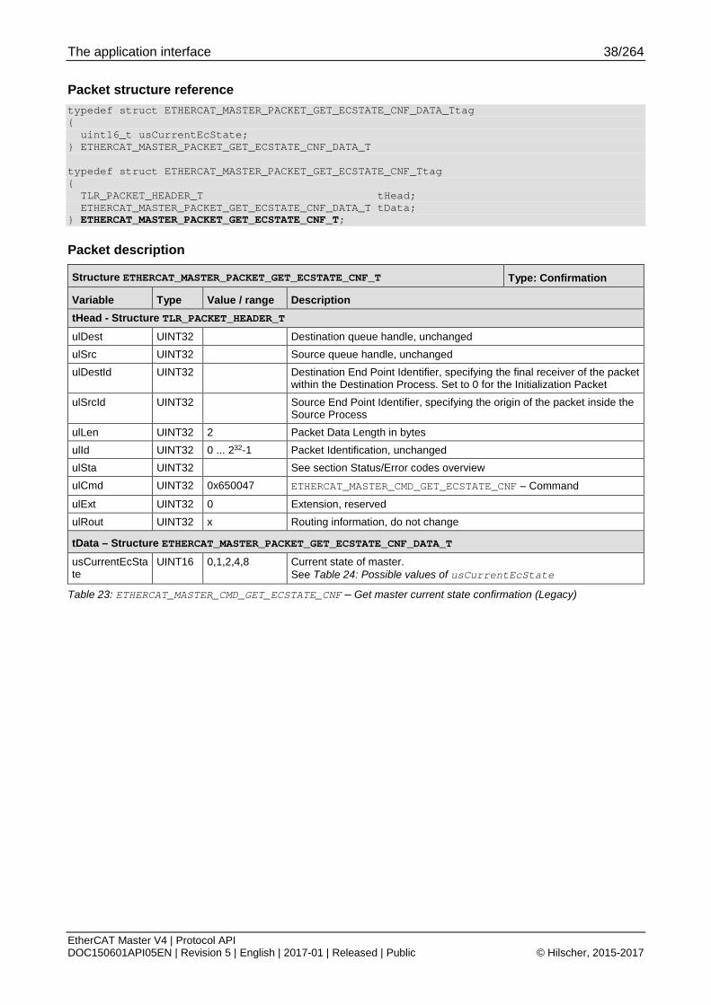
4.4.4.2 Get Current State (Legacy)
This service retrieves the current network status of the master.
Packet structure reference typedef struct ETHERCAT_MASTER_PACKET_GET_ECSTATE_REQ_Ttag { TLR_PACKET_HEADER_T tHead; } ETHERCAT_MASTER_PACKET_GET_ECSTATE_REQ_T;
Packet description
Structure ETHERCAT_MASTER_PACKET_GET_ECSTATE_REQ_T Type: Request
Variable Type Value / range Description tHead - Structure TLR_PACKET_HEADER_T ulDest UINT32 Destination queue-handle ulSrc UINT32 Source queue-handle ulDestId UINT32 Destination End Point Identifier, specifying the final receiver of the
packet within the Destination Process. Set to 0 for the Initialization Packet
ulSrcId UINT32 Source End Point Identifier, specifying the origin of the packet inside the Source Process
ulLen UINT32 0 Packet Data Length in bytes ulId UINT32 0 ... 232-1 Packet Identification as unique number generated by the Source
Process of the Packet ulSta UINT32 See section Status/Error codes overview ulCmd UINT32 0x650046 ETHERCAT_MASTER_CMD_GET_ECSTATE_REQ - Command
ulExt UINT32 0 Extension not in use, set to zero for compatibility reasons ulRout UINT32 x Routing, do not touch
Table 22: ETHERCAT_MASTER_CMD_GET_ECSTATE_REQ – Get master current state request (Legacy)
The application interface 38/264
EtherCAT Master V4 | Protocol API DOC150601API05EN | Revision 5 | English | 2017-01 | Released | Public © Hilscher, 2015-2017
Packet structure reference typedef struct ETHERCAT_MASTER_PACKET_GET_ECSTATE_CNF_DATA_Ttag { uint16_t usCurrentEcState; } ETHERCAT_MASTER_PACKET_GET_ECSTATE_CNF_DATA_T typedef struct ETHERCAT_MASTER_PACKET_GET_ECSTATE_CNF_Ttag { TLR_PACKET_HEADER_T tHead; ETHERCAT_MASTER_PACKET_GET_ECSTATE_CNF_DATA_T tData; } ETHERCAT_MASTER_PACKET_GET_ECSTATE_CNF_T;
Packet description
Structure ETHERCAT_MASTER_PACKET_GET_ECSTATE_CNF_T Type: Confirmation
Variable Type Value / range Description tHead - Structure TLR_PACKET_HEADER_T ulDest UINT32 Destination queue handle, unchanged ulSrc UINT32 Source queue handle, unchanged ulDestId UINT32 Destination End Point Identifier, specifying the final receiver of the packet
within the Destination Process. Set to 0 for the Initialization Packet ulSrcId UINT32 Source End Point Identifier, specifying the origin of the packet inside the
Source Process ulLen UINT32 2 Packet Data Length in bytes ulId UINT32 0 ... 232-1 Packet Identification, unchanged ulSta UINT32 See section Status/Error codes overview ulCmd UINT32 0x650047 ETHERCAT_MASTER_CMD_GET_ECSTATE_CNF – Command
ulExt UINT32 0 Extension, reserved ulRout UINT32 x Routing information, do not change
tData – Structure ETHERCAT_MASTER_PACKET_GET_ECSTATE_CNF_DATA_T usCurrentEcState
UINT16 0,1,2,4,8 Current state of master. See Table 24: Possible values of usCurrentEcState
Table 23: ETHERCAT_MASTER_CMD_GET_ECSTATE_CNF – Get master current state confirmation (Legacy)

The application interface 39/264
EtherCAT Master V4 | Protocol API DOC150601API05EN | Revision 5 | English | 2017-01 | Released | Public © Hilscher, 2015-2017
Defined values for usCurrentEcState
Value Definition / description 0x0000 ECM_IF_STATE_BUSOFF / ETHERCAT_MASTER_BUSSTATE_UNKNOWN
Master is in state Bus off 0x0001 ECM_IF_STATE_INIT / ETHERCAT_MASTER_BUSSTATE_INIT
Master is in state INIT 0x0002 ECM_IF_STATE_PREOP / ETHERCAT_MASTER_BUSSTATE_PREOP
Master is in state PREOP 0x0004 ECM_IF_STATE_SAFEOP / ETHERCAT_MASTER_BUSSTATE_SAFEOP
Master is in state SAFEOP 0x0008 ECM_IF_STATE_OP / ETHERCAT_MASTER_BUSSTATE_OP
Master is in state OP
Table 24: Possible values of usCurrentEcState
The application interface 40/264
EtherCAT Master V4 | Protocol API DOC150601API05EN | Revision 5 | English | 2017-01 | Released | Public © Hilscher, 2015-2017
4.4.5 Slave state
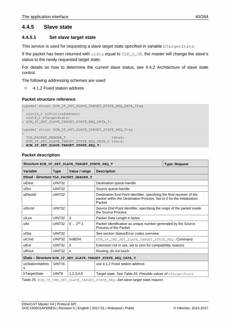
4.4.5.1 Set slave target state
This service is used for requesting a slave target state specified in variable bTargetState.
If the packet has been returned with ulSta equal to TLR_S_OK, the master will change the slave’s status to the newly requested target state.
For details on how to determine the current slave status, see 4.4.2 Architecture of slave state control.
The following addressing schemes are used:
4.1.2 Fixed station address
Packet structure reference typedef struct ECM_IF_SET_SLAVE_TARGET_STATE_REQ_DATA_Ttag { uint16_t usStationAddress; uint8_t bTargetState; } ECM_IF_SET_SLAVE_TARGET_STATE_REQ_DATA_T; typedef struct ECM_IF_SET_SLAVE_TARGET_STATE_REQ_Ttag { TLR_PACKET_HEADER_T tHead; ECM_IF_SET_SLAVE_TARGET_STATE_REQ_DATA_T tData; } ECM_IF_SET_SLAVE_TARGET_STATE_REQ_T;
Packet description
Structure ECM_IF_SET_SLAVE_TARGET_STATE_REQ_T Type: Request
Variable Type Value / range Description tHead - Structure TLR_PACKET_HEADER_T ulDest UINT32 Destination queue-handle ulSrc UINT32 Source queue-handle ulDestId UINT32 Destination End Point Identifier, specifying the final receiver of the
packet within the Destination Process. Set to 0 for the Initialization Packet
ulSrcId UINT32 Source End Point Identifier, specifying the origin of the packet inside the Source Process
ulLen UINT32 3 Packet Data Length in bytes ulId UINT32 0 ... 232-1 Packet Identification as unique number generated by the Source
Process of the Packet
ulSta UINT32 See section Status/Error codes overview ulCmd UINT32 0x9E04 ECM_IF_CMD_SET_SLAVE_TARGET_STATE_REQ - Command
ulExt UINT32 0 Extension not in use, set to zero for compatibility reasons ulRout UINT32 x Routing, do not touch
tData – Structure ECM_IF_SET_SLAVE_TARGET_STATE_REQ_DATA_T usStationAddress
UINT16 use 4.1.2 Fixed station address
bTargetState UINT8 1,2,3,4,8 Target state. See Table 26: Possible values of bTargetState
Table 25: ECM_IF_CMD_SET_SLAVE_TARGET_STATE_REQ –Set slave target state request

The application interface 41/264
EtherCAT Master V4 | Protocol API DOC150601API05EN | Revision 5 | English | 2017-01 | Released | Public © Hilscher, 2015-2017
Defined values for bTargetState
Value Definition / description 0x01 ECM_IF_STATE_INIT
Slave is requested to be in state INIT 0x02 ECM_IF_STATE_PREOP
Slave is requested to be in state PREOP 0x03 ECM_IF_STATE_BOOT
Slave is requested to be in state BOOT 0x04 ECM_IF_STATE_SAFEOP
Slave is requested to be in state SAFEOP 0x08 ECM_IF_STATE_OP
Slave is requested to be in state OP
Table 26: Possible values of bTargetState
Packet structure reference typedef struct ECM_IF_SET_SLAVE_TARGET_STATE_CNF_DATA_Ttag { uint16_t usStationAddress; uint8_t bTargetState; } ECM_IF_SET_SLAVE_TARGET_STATE_CNF_DATA_T typedef struct ECM_IF_SET_SLAVE_TARGET_STATE_CNF_Ttag { TLR_PACKET_HEADER_T tHead; ECM_IF_SET_SLAVE_TARGET_STATE_CNF_DATA_T tData; } ECM_IF_SET_SLAVE_TARGET_STATE_CNF_T;
Packet description
Structure ECM_IF_SET_SLAVE_TARGET_STATE_CNF_T Type: Confirmation
Variable Type Value / range Description tHead - Structure TLR_PACKET_HEADER_T ulDest UINT32 Destination queue handle, unchanged ulSrc UINT32 Source queue handle, unchanged ulDestId UINT32 Destination End Point Identifier, specifying the final receiver of the packet
within the Destination Process. Set to 0 for the Initialization Packet ulSrcId UINT32 Source End Point Identifier, specifying the origin of the packet inside the
Source Process ulLen UINT32 3 Packet Data Length in bytes ulId UINT32 0 ... 232-1 Packet Identification, unchanged ulSta UINT32 See section Status/Error codes overview ulCmd UINT32 0x9E05 ECM_IF_CMD_SET_SLAVE_TARGET_STATE_CNF – Command
ulExt UINT32 0 Extension, reserved ulRout UINT32 x Routing information, do not change
tData – Structure ECM_IF_SET_SLAVE_TARGET_STATE_CNF_DATA_T usStationAddress
UINT16 Valid address Same value as specified in request for station address
bTargetState UINT8 1,2,3,4,8 Same value as specified in request for target state
Table 27: ECM_IF_CMD_SET_SLAVE_TARGET_STATE_CNF – Set slave target state confirmation

The application interface 42/264
EtherCAT Master V4 | Protocol API DOC150601API05EN | Revision 5 | English | 2017-01 | Released | Public © Hilscher, 2015-2017
4.4.5.2 Get current slave state
This service retrieves the current and target network status of a specified slave.
The following addressing schemes are used:
4.1.2 Fixed station address
Packet structure reference typedef struct ECM_IF_GET_SLAVE_CURRENT_STATE_REQ_DATA_Ttag { uint16_t usStationAddress; } ECM_IF_GET_SLAVE_CURRENT_STATE_REQ_DATA_T; typedef struct ECM_IF_GET_SLAVE_CURRENT_STATE_REQ_Ttag { TLR_PACKET_HEADER_T tHead; ECM_IF_GET_SLAVE_CURRENT_STATE_REQ_DATA_T tData; } ECM_IF_GET_SLAVE_CURRENT_STATE_REQ_T;
Packet description
Structure ECM_IF_GET_SLAVE_CURRENT_STATE_REQ_T Type: Request
Variable Type Value / range Description tHead - Structure TLR_PACKET_HEADER_T ulDest UINT32 Destination queue-handle ulSrc UINT32 Source queue-handle ulDestId UINT32 Destination End Point Identifier, specifying the final receiver of the
packet within the Destination Process. Set to 0 for the Initialization Packet
ulSrcId UINT32 Source End Point Identifier, specifying the origin of the packet inside the Source Process
ulLen UINT32 2 Packet Data Length in bytes ulId UINT32 0 ... 232-1 Packet Identification as unique number generated by the Source
Process of the Packet ulSta UINT32 See section Status/Error codes overview ulCmd UINT32 0x9E06 ECM_IF_CMD_GET_SLAVE_CURRENT_STATE_REQ - Command
ulExt UINT32 0 Extension not in use, set to zero for compatibility reasons ulRout UINT32 x Routing, do not touch
tData – Structure ECM_IF_GET_SLAVE_CURRENT_STATE_REQ_DATA_T usStationAddress
UINT16 use 4.1.2 Fixed station address
Table 28: ECM_IF_CMD_GET_SLAVE_CURRENT_STATE_REQ – Get slave current state request

The application interface 43/264
EtherCAT Master V4 | Protocol API DOC150601API05EN | Revision 5 | English | 2017-01 | Released | Public © Hilscher, 2015-2017
Packet structure reference typedef struct ECM_IF_GET_SLAVE_CURRENT_STATE_CNF_DATA_Ttag { uint16_t usStationAddress; uint8_t bCurrentState; uint8_t bTargetState; uint32_t ulActiveError; } ECM_IF_GET_SLAVE_CURRENT_STATE_CNF_DATA_T typedef struct ECM_IF_GET_SLAVE_CURRENT_STATE_CNF_Ttag { TLR_PACKET_HEADER_T tHead; ECM_IF_GET_SLAVE_CURRENT_STATE_CNF_DATA_T tData; } ECM_IF_GET_SLAVE_CURRENT_STATE_CNF_T;
Packet description
Structure ECM_IF_GET_SLAVE_CURRENT_STATE_CNF_T Type: Confirmation
Variable Type Value / range Description tHead - Structure TLR_PACKET_HEADER_T ulDest UINT32 Destination queue handle, unchanged ulSrc UINT32 Source queue handle, unchanged ulDestId UINT32 Destination End Point Identifier, specifying the final receiver of the packet
within the Destination Process. Set to 0 for the Initialization Packet ulSrcId UINT32 Source End Point Identifier, specifying the origin of the packet inside the
Source Process ulLen UINT32 8 Packet Data Length in bytes ulId UINT32 0 ... 232-1 Packet Identification, unchanged ulSta UINT32 See section Status/Error codes overview ulCmd UINT32 0x9E07 ECM_IF_CMD_GET_SLAVE_CURRENT_STATE_CNF – Command
ulExt UINT32 0 Extension, reserved ulRout UINT32 x Routing information, do not change
tData – Structure ECM_IF_GET_SLAVE_CURRENT_STATE_CNF_DATA_T usStationAddress
UINT16 Same value as given in request
bCurrentState UINT8 0,1,2,3,4,8, 0x11,0x12,0x13,0x14
Current state of slave. See Table 30: Possible values of bCurrentState
bTargetState UINT8 1,2,3,4,8 Target state of slave See Table 31: Possible values of bTargetState
ulActiveError UINT32 If it equals 0, the state change is progressing or successful. If it is unequal 0, the last state change stopped. See Status/Error codes overview
Table 29: ECM_IF_CMD_GET_SLAVE_CURRENT_STATE_CNF – Get slave current state confirmation
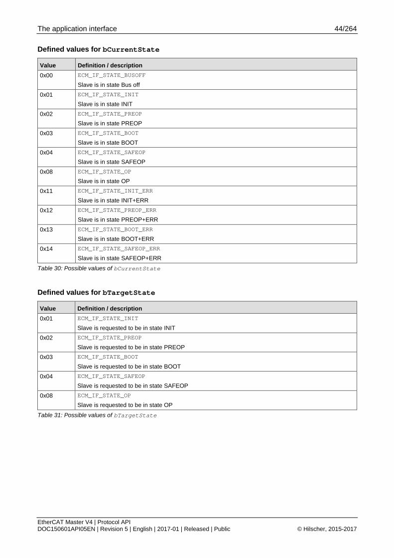
The application interface 44/264
EtherCAT Master V4 | Protocol API DOC150601API05EN | Revision 5 | English | 2017-01 | Released | Public © Hilscher, 2015-2017
Defined values for bCurrentState
Value Definition / description 0x00 ECM_IF_STATE_BUSOFF
Slave is in state Bus off 0x01 ECM_IF_STATE_INIT
Slave is in state INIT 0x02 ECM_IF_STATE_PREOP
Slave is in state PREOP 0x03 ECM_IF_STATE_BOOT
Slave is in state BOOT 0x04 ECM_IF_STATE_SAFEOP
Slave is in state SAFEOP 0x08 ECM_IF_STATE_OP
Slave is in state OP 0x11 ECM_IF_STATE_INIT_ERR
Slave is in state INIT+ERR 0x12 ECM_IF_STATE_PREOP_ERR
Slave is in state PREOP+ERR 0x13 ECM_IF_STATE_BOOT_ERR
Slave is in state BOOT+ERR 0x14 ECM_IF_STATE_SAFEOP_ERR
Slave is in state SAFEOP+ERR
Table 30: Possible values of bCurrentState
Defined values for bTargetState
Value Definition / description 0x01 ECM_IF_STATE_INIT
Slave is requested to be in state INIT 0x02 ECM_IF_STATE_PREOP
Slave is requested to be in state PREOP 0x03 ECM_IF_STATE_BOOT
Slave is requested to be in state BOOT 0x04 ECM_IF_STATE_SAFEOP
Slave is requested to be in state SAFEOP 0x08 ECM_IF_STATE_OP
Slave is requested to be in state OP
Table 31: Possible values of bTargetState

The application interface 45/264
EtherCAT Master V4 | Protocol API DOC150601API05EN | Revision 5 | English | 2017-01 | Released | Public © Hilscher, 2015-2017
4.5 Status indications
4.5.1 Registration and deregistration of status indications
4.5.1.1 Register for status indications service
This packet registers an application task for receiving status indications.
The following groups of status indications will be sent to the application task after successful registration:
4.5.2 Available indications
If the application does not want to receive those indications anymore, it has to use the service described in 4.5.1.2 Unregister from status indications service.
Packet structure reference typedef struct RCX_REGISTER_APP_REQ_Ttag { TLR_PACKET_HEADER_T tHead; } RCX_REGISTER_APP_REQ_T;
Packet description
Structure RCX_REGISTER_APP_REQ_T Type: Request
Variable Type Value / range Description tHead - Structure TLR_PACKET_HEADER_T ulDest UINT32 Destination queue-handle ulSrc UINT32 Source queue-handle ulDestId UINT32 Destination End Point Identifier, specifying the final receiver of the
packet within the Destination Process. Set to 0 for the Initialization Packet
ulSrcId UINT32 Source End Point Identifier, specifying the origin of the packet inside the Source Process
ulLen UINT32 0 Packet Data Length in bytes ulId UINT32 0 ... 232-1 Packet Identification as unique number generated by the Source
Process of the Packet ulSta UINT32 See section Status/Error codes overview ulCmd UINT32 0x2F10 RCX_REGISTER_APP_REQ - Command
ulExt UINT32 0 Extension not in use, set to zero for compatibility reasons ulRout UINT32 x Routing, do not touch
Table 32: RCX_REGISTER_APP_REQ – Register for status indications request

The application interface 46/264
EtherCAT Master V4 | Protocol API DOC150601API05EN | Revision 5 | English | 2017-01 | Released | Public © Hilscher, 2015-2017
Packet structure reference typedef struct RCX_REGISTER_APP_CNF_Ttag { TLR_PACKET_HEADER_T tHead; } RCX_REGISTER_APP_CNF_T;
Packet description
Structure RCX_REGISTER_APP_CNF_T Type: Confirmation
Variable Type Value / range Description tHead - Structure TLR_PACKET_HEADER_T
ulDest UINT32 Destination queue handle, unchanged ulSrc UINT32 Source queue handle, unchanged ulDestId UINT32 Destination End Point Identifier, specifying the final receiver of the
packet within the Destination Process. Set to 0 for the Initialization Packet
ulSrcId UINT32 Source End Point Identifier, specifying the origin of the packet inside the Source Process
ulLen UINT32 0 Packet Data Length in bytes ulId UINT32 0 ... 232-1 Packet Identification, unchanged ulSta UINT32 See section Status/Error codes overview ulCmd UINT32 0x2F11 RCX_REGISTER_APP_CNF – Command
ulExt UINT32 0 Extension, reserved ulRout UINT32 x Routing information, do not change
Table 33: RCX_REGISTER_APP_CNF – Register for status indications confirmation

The application interface 47/264
EtherCAT Master V4 | Protocol API DOC150601API05EN | Revision 5 | English | 2017-01 | Released | Public © Hilscher, 2015-2017
4.5.1.2 Unregister from status indications service
This packet deregisters an application task from receiving status indications.
The following status indications will not continue to be sent to the application task anymore after successful deregistration:
4.5.2 Available indications
Packet structure reference typedef struct RCX_UNREGISTER_APP_REQ_Ttag { TLR_PACKET_HEADER_T tHead; } RCX_UNREGISTER_APP_REQ_T;
Packet description
Structure RCX_UNREGISTER_APP_REQ_T Type: Request
Variable Type Value / range Description tHead - Structure TLR_PACKET_HEADER_T ulDest UINT32 Destination queue-handle ulSrc UINT32 Source queue-handle ulDestId UINT32 Destination End Point Identifier, specifying the final receiver of the
packet within the Destination Process. Set to 0 for the Initialization Packet
ulSrcId UINT32 Source End Point Identifier, specifying the origin of the packet inside the Source Process
ulLen UINT32 0 Packet Data Length in bytes ulId UINT32 0 ... 232-1 Packet Identification as unique number generated by the Source
Process of the Packet ulSta UINT32 See section Status/Error codes overview ulCmd UINT32 0x2F12 RCX_UNREGISTER_APP_REQ - Command
ulExt UINT32 0 Extension not in use, set to zero for compatibility reasons ulRout UINT32 x Routing, do not touch
Table 34: RCX_UNREGISTER_APP_REQ –Unregister from status indications request

The application interface 48/264
EtherCAT Master V4 | Protocol API DOC150601API05EN | Revision 5 | English | 2017-01 | Released | Public © Hilscher, 2015-2017
Packet structure reference typedef struct RCX_UNREGISTER_APP_CNF_Ttag { TLR_PACKET_HEADER_T tHead; } RCX_UNREGISTER_APP_CNF_T;
Packet description
Structure RCX_UNREGISTER_APP_CNF_T Type: Confirmation
Variable Type Value / range Description tHead - Structure TLR_PACKET_HEADER_T
ulDest UINT32 Destination queue handle, unchanged ulSrc UINT32 Source queue handle, unchanged ulDestId UINT32 Destination End Point Identifier, specifying the final receiver of the
packet within the Destination Process. Set to 0 for the Initialization Packet
ulSrcId UINT32 Source End Point Identifier, specifying the origin of the packet inside the Source Process
ulLen UINT32 0 Packet Data Length in bytes ulId UINT32 0 ... 232-1 Packet Identification, unchanged ulSta UINT32 See section Status/Error codes overview ulCmd UINT32 0x2F13 RCX_UNREGISTER_APP_CNF – Command
ulExt UINT32 0 Extension, reserved ulRout UINT32 x Routing information, do not change
Table 35: RCX_UNREGISTER_APP_CNF – Unregister from status indications confirmation

The application interface 49/264
EtherCAT Master V4 | Protocol API DOC150601API05EN | Revision 5 | English | 2017-01 | Released | Public © Hilscher, 2015-2017
4.5.2 Available indications
4.5.2.1 Master state indication
This packet indicates the new state of the master. For details on how this indication relates to master state control, see 4.4.1 Architecture of master state control.
Packet structure reference typedef struct ECM_IF_GET_MASTER_CURRENT_STATE_IND_DATA_Ttag { uint8_t bCurrentState; uint8_t bTargetState; uint32_t ulStopReason; uint32_t ulMasterStatusFlags; } ECM_IF_GET_MASTER_CURRENT_STATE_IND_DATA_T; typedef struct ECM_IF_GET_MASTER_CURRENT_STATE_IND_Ttag { TLR_PACKET_HEADER_T tHead; ECM_IF_GET_MASTER_CURRENT_STATE_IND_DATA_T tData; } ECM_IF_GET_MASTER_CURRENT_STATE_IND_T;
Packet description
Structure ECM_IF_GET_MASTER_CURRENT_STATE_IND_T Type: Indication
Variable Type Value / range Description tHead - Structure TLR_PACKET_HEADER_T
ulDest UINT32 Destination queue-handle ulSrc UINT32 Source queue-handle ulDestId UINT32 Destination End Point Identifier, specifying the final receiver of the
packet within the Destination Process. Set to 0 for the Initialization Packet
ulSrcId UINT32 Source End Point Identifier, specifying the origin of the packet inside the Source Process
ulLen UINT32 10 Packet Data Length in bytes ulId UINT32 0 ... 232-1 Packet Identification as unique number generated by the Source
Process of the Packet ulSta UINT32 See section Status/Error codes overview ulCmd UINT32 0x9E10 ECM_IF_CMD_GET_MASTER_CURRENT_STATE_IND - Command
ulExt UINT32 0 Extension not in use, set to zero for compatibility reasons ulRout UINT32 x Routing, do not touch
tData – Structure ECM_IF_GET_MASTER_CURRENT_STATE_IND_DATA_T bCurrentState UINT8 0,1,2,4,8,
0x18,0x1D,0x1E,0x1F
Current state of master. See Table 37: Possible values of bCurrentState
bTargetState UINT8 1,2,4,8 Target state of master See Table 38: Possible values of bTargetState
ulStopReason UINT32 If it equals 0, the state change is progressing or successful. If it is unequal 0, the last state change stopped. See Status/Error codes overview
ulMasterStatusFlags
UINT32 0-7 Master status flags. See Table 39: Meaning of ulMasterFlags
Table 36: ECM_IF_CMD_GET_MASTER_CURRENT_STATE_IND – Master state indication

The application interface 50/264
EtherCAT Master V4 | Protocol API DOC150601API05EN | Revision 5 | English | 2017-01 | Released | Public © Hilscher, 2015-2017
Defined values for bCurrentState
Value Definition / description 0x00 ECM_IF_STATE_BUSOFF
Master is in state Bus off 0x01 ECM_IF_STATE_INIT
Master is in state INIT 0x02 ECM_IF_STATE_PREOP
Master is in state PREOP 0x04 ECM_IF_STATE_SAFEOP
Master is in state SAFEOP 0x08 ECM_IF_STATE_OP
Master is in state OP 0x18 ECM_IF_STATE_LEAVE_OP
Master is leaving OP state This state is signaled when master begins processing a state change away from OP
0x1D ECM_IF_STATE_BUSSCAN_COMPLETE_NO_PREOP
Legacy bus scan completed 0x1E ECM_IF_STATE_BUSSCAN
Bus scan in progress 0x1F ECM_IF_STATE_BUSSCAN_COMPLETE
Bus scan is completed and PREOP is reached with all slaves.
Table 37: Possible values of bCurrentState
Defined values for bTargetState
Value Definition / description 0x01 ECM_IF_STATE_INIT
Master is requested to be in state INIT 0x02 ECM_IF_STATE_PREOP
Master is requested to be in state PREOP 0x04 ECM_IF_STATE_SAFEOP
Master is requested to be in state SAFEOP 0x08 ECM_IF_STATE_OP
Master is requested to be in state OP
Table 38: Possible values of bTargetState

The application interface 51/264
EtherCAT Master V4 | Protocol API DOC150601API05EN | Revision 5 | English | 2017-01 | Released | Public © Hilscher, 2015-2017
Bit mask for ulMasterFlags
Bit No. Definition / description
31-3 RESERVED
Reserved, set to 0.
2 MSK_ECM_IF_MASTER_STATUS_FLAGS_AT_LEAST_ONE_MANDATORY_SLAVE_NOT_IN_OP
If this bit is set, at least one mandatory slave is not in OP when master is in OP. But, the slave is still connected.
1 MSK_ECM_IF_MASTER_STATUS_FLAGS_DC_XRMW_STOPPED
If this bit is set, the DC handling stopped sending ARMW/FRMW telegrams. The DC Slaves are not synchronizing their sys time in that case.
0 MSK_ECM_IF_MASTER_STATUS_FLAGS_AT_LEAST_ONE_MANDATORY_SLAVE_LOST
If this bit is set, at least one mandatory slave is not connected to master anymore.
Table 39: Meaning of ulMasterFlags
Packet structure reference typedef struct ECM_IF_MASTER_CURRENT_STATE_RES_Ttag { TLR_PACKET_HEADER_T tHead;
} ECM_IF_MASTER_CURRENT_STATE_RES_T;
Packet description
Structure ECM_IF_MASTER_CURRENT_STATE_RES_T Type: Response
Variable Type Value / range Description tHead - Structure TLR_PACKET_HEADER_T ulDest UINT32 Destination queue handle, unchanged ulSrc UINT32 Source queue handle, unchanged ulDestId UINT32 Destination End Point Identifier, specifying the final receiver of the
packet within the Destination Process. Set to 0 for the Initialization Packet
ulSrcId UINT32 Source End Point Identifier, specifying the origin of the packet inside the Source Process
ulLen UINT32 0 Packet Data Length in bytes ulId UINT32 0 ... 232-1 Packet Identification, unchanged ulSta UINT32 See section Status/Error codes overview ulCmd UINT32 0x9E11 ECM_IF_CMD_MASTER_CURRENT_STATE_RES – Command
ulExt UINT32 0 Extension, reserved ulRout UINT32 x Routing information, do not change
Table 40: ECM_IF_CMD_MASTER_CURRENT_STATE_RES – Response to master state indication

The application interface 52/264
EtherCAT Master V4 | Protocol API DOC150601API05EN | Revision 5 | English | 2017-01 | Released | Public © Hilscher, 2015-2017
4.6 Diagnostic log The diagnostic log provides a single entry point to EtherCAT-specific diagnostic information from the master. This includes several data points e.g. topology state, slave state and so on.
4.6.1 Entry format of diagnostic log
4.6.1.1 General format
The general format is based on a header and a union to provide a common format for all possible entries. The basic layout is provided here:
Diagnostic log entry structure typedef struct ECM_DIAG_ENTRY_Ttag { ECM_DIAG_ENTRY_HEADER_T tHead; ECM_DIAG_ENTRY_DATA_T tData; } ECM_DIAG_ENTRY_T;
Structure ECM_DIAG_ENTRY_T
Variable name Type Meaning
tHead ECM_DIAG_ENTRY_HEADER_T
Entry header
see 4.6.1.2 Entry header for details
tData ECM_DIAG_ENTRY_DATA_T
Entry data
see 4.6.1.3 Entry data format for details
Table 41: Structure ECM_DIAG_ENTRY_T

The application interface 53/264
EtherCAT Master V4 | Protocol API DOC150601API05EN | Revision 5 | English | 2017-01 | Released | Public © Hilscher, 2015-2017
4.6.1.2 Entry header
The entry header is used for all diagnostic log entries. Its main purpose is to designate the type and the time stamp of the entry.
ECM_DIAG_ENTRY_HEADER_T Structure Reference typedef struct ECM_DIAG_ENTRY_HEADER_Ttag { uint16_t usEntryType; uint64_t ullTimestampNs; } ECM_DIAG_ENTRY_HEADER_T;
Structure ECM_DIAG_ENTRY_HEADER_T
Variable name Type Meaning
usEntryType UINT16 Entry type
ulTimestampNs UINT64 Timestamp (Nanoseconds, see above)
Table 42: Structure ECM_DIAG_ENTRY_HEADER_T
Defined values for usEntryType
Value Definition / description 0x0001 VAL_ECM_DIAG_ENTRY_TYPE_NEW_STATE
New master state see 4.6.1.4 Entry: New communication state for data format
0x0002 VAL_ECM_DIAG_ENTRY_TYPE_BUS_ON
Bus on
see 4.6.1.5 Entry: BusOn for data format
0x0003 VAL_ECM_DIAG_ENTRY_TYPE_BUS_OFF
Bus off
see 4.6.1.6 Entry: BusOff for data format
0x0004 VAL_ECM_DIAG_ENTRY_TYPE_CHANNEL_INIT
A channel Init occurred
see 4.6.1.7 Entry: ChannelInit for data format
0x0005 VAL_ECM_DIAG_ENTRY_TYPE_DPM_WATCHDOG
A DPM watchdog error occurred
see 4.6.1.8 Entry: DPM watchdog for data format
0x0007 VAL_ECM_DIAG_ENTRY_TYPE_INTERNAL_ERROR
Internal error see 4.6.1.9 Entry: Internal error for data format
0x0008 VAL_ECM_DIAG_ENTRY_TYPE_ALL_SLAVES_LOST
All slaves were disconnected. see 4.6.1.10 Entry: All slaves lost for data format
0x0009 VAL_ECM_DIAG_ENTRY_TYPE_BUS_SCAN_REQUESTED
A bus scan has been requested. see 4.6.1.11 Entry: Bus scan requested for data format
0x000A VAL_ECM_DIAG_ENTRY_TYPE_IDENTITY_MISMATCH
Identity data mismatch for a slave detected. see 4.6.1.12 Entry: Identity mismatch for data format

The application interface 54/264
EtherCAT Master V4 | Protocol API DOC150601API05EN | Revision 5 | English | 2017-01 | Released | Public © Hilscher, 2015-2017
Value Definition / description 0x000B VAL_ECM_DIAG_ENTRY_TYPE_COE_INITCMD_FAILED
CoE InitCmd Failed see 4.6.1.13 Entry: CoE InitCmd failed for data format
0x000C VAL_ECM_DIAG_ENTRY_TYPE_SOE_INITCMD_FAILED
SoE InitCmd Failed see 4.6.1.14 Entry: SoE InitCmd failed for data format
0x000F VAL_ECM_DIAG_ENTRY_TYPE_REG_INITCMD_WARNING
Register InitCmd Warning see 4.6.1.15 Entry: Reg InitCmd warning for data format
0x0010 VAL_ECM_DIAG_ENTRY_TYPE_REG_INITCMD_FAILED
Register InitCmd Failed see 4.6.1.16 Entry: Reg InitCmd failed for data format
0x0011 VAL_ECM_DIAG_ENTRY_TYPE_ALCONTROL_FAILED
ALControl Request Failed see 4.6.1.17 Entry: ALControl failed for data format
0x0012 VAL_ECM_DIAG_ENTRY_TYPE_SII_ASSIGN_TO_ECAT_FAILED
SII Assign To ECAT Failed see 4.6.1.18 Entry: SII Assign to EtherCAT failed for data format
0x0013 VAL_ECM_DIAG_ENTRY_TYPE_SII_ASSIGN_TO_PDI_FAILED
SII Assign To PDI Failed see 4.6.1.19 Entry: SII Assign to PDI failed for data format
0x0014 VAL_ECM_DIAG_ENTRY_TYPE_SII_READ_REQUEST_FAILED
SII Read Request Failed see 4.6.1.20 Entry: SII Read request failed for data format
0x0015 VAL_ECM_DIAG_ENTRY_TYPE_SLAVE_WANING
Slave Warning see 4.6.1.21 Entry: Slave warning for data format
0x0016 VAL_ECM_DIAG_ENTRY_TYPE_SLAVE_ERROR
Slave Error see 4.6.1.22 Entry: Slave error for data format
Table 43: Possible values of usEntryType for diagnostic log
ullTimestampNs
ullTimestampNs forms a large 64-bit nanosecond timestamp.
ullTimestampNs ranges from 0 ... 0xFFFFFFFFFFFFFF and is displayed in nanoseconds.

The application interface 55/264
EtherCAT Master V4 | Protocol API DOC150601API05EN | Revision 5 | English | 2017-01 | Released | Public © Hilscher, 2015-2017
4.6.1.3 Entry data format
The union referenced via tData contains all possible formats. The currently used format depends on the entry type (usEntryType) set in the header.
ECM_DIAG_ENTRY_DATA_T Structure Reference typedef union ECM_DIAG_ENTRY_DATA_Ttag { ECM_DIAG_ENTRY_NEW_STATE_T tNewState; ECM_DIAG_ENTRY_INTERNAL_ERROR_T tInternalError; ECM_DIAG_ENTRY_IDENTITY_MISMATCH_T tIdentityMismatch; ECM_DIAG_ENTRY_COE_INITCMD_FAILED_T tCoEInitCmdFailed; ECM_DIAG_ENTRY_SOE_INITCMD_FAILED_T tSoEInitCmdFailed; ECM_DIAG_ENTRY_REG_INITCMD_INFO_T tRegInitCmdInfo; ECM_DIAG_ENTRY_ALCONTROL_FAILED_T tAlControlFailed; ECM_DIAG_ENTRY_SII_ASSIGN_FAILED_T tSiiAssignFailed; ECM_DIAG_ENTRY_SII_REQUEST_FAILED_T tSiiRequestFailed; ECM_DIAG_ENTRY_SLAVE_WARNING_T tSlaveWarning; ECM_DIAG_ENTRY_SLAVE_ERROR_T tSlaveError; } ECM_DIAG_ENTRY_DATA_T;
The elements of the union will be detailed in following chapters.
Note: Sections may repeat certain structure references for clarity.
4.6.1.4 Entry: New communication state
This entry designates what master state has been reached.
Entry structure reference typedef struct ECM_DIAG_ENTRY_NEW_STATE_Ttag { uint8_t bState; } ECM_DIAG_ENTRY_NEW_STATE_T;
Structure ECM_DIAG_ENTRY_NEW_STATE_T
Variable name Type Meaning
bState UINT8 New master state
Table 44: Structure ECM_DIAG_ENTRY_NEW_STATE_T
Coding of bState
Available Reason Codes for bState
Value Definition / description
0x00 Bus Off reached
0x01 INIT reached
0x02 PREOP reached
0x04 SAFEOP reached
0x08 OP reached
Table 45: Coding of master state in bState

The application interface 56/264
EtherCAT Master V4 | Protocol API DOC150601API05EN | Revision 5 | English | 2017-01 | Released | Public © Hilscher, 2015-2017
4.6.1.5 Entry: BusOn
This entry is recorded when a BusOn has been requested.
There is no additional data contained within the entry data.
4.6.1.6 Entry: BusOff
This entry is recorded when a BusOff has been requested.
There is no additional data contained within the entry data.
4.6.1.7 Entry: ChannelInit
This entry is recorded when a ChannelInit has been requested.
There is no additional data contained within the entry data.
4.6.1.8 Entry: DPM watchdog
This entry is recorded when a DPM watchdog timeout event has occurred.
There is no additional data contained within the entry data.
4.6.1.9 Entry: Internal error
This entry is recorded whenever the master detects an internal error. In case of problems, it is helpful to provide the data of the entry and a description of the problem to our support.
Entry structure reference typedef struct ECM_DIAG_ENTRY_INTERNAL_ERROR_Ttag { uint32_t ulFunctionId; uint32_t ulErrorCode; } ECM_ENTRY_INTERNAL_ERROR_T;
Entry structure description
Structure ECM_DIAG_ENTRY_INTERNAL_ERROR_T
Variable name Type Meaning
ulFunctionId UINT32 Function ID
ulErrorCode UINT32 Error Code
Table 46: Structure ECM_DIAG_ENTRY_INTERNAL_ERROR_T

The application interface 57/264
EtherCAT Master V4 | Protocol API DOC150601API05EN | Revision 5 | English | 2017-01 | Released | Public © Hilscher, 2015-2017
4.6.1.10 Entry: All slaves lost
This entry is recorded when no slave is left to communicate with. In that case, the master will autonomously fallback to INIT and retry to startup the bus again.
There is no additional data contained within the entry data.
4.6.1.11 Entry: Bus scan requested
This entry is recorded when the application requested a bus scan.
There is no additional data contained within the entry data.
4.6.1.12 Entry: Identity mismatch
This entry is recorded when a slave is not matching the expected slave in terms of identity data.
Entry structure reference typedef struct ECM_DIAG_ENTRY_IDENTITY_MISMATCH_Ttag { uint16_t usTopologyPosition; uint16_t usCompareFlags; uint32_t ulExpectedVendorId; uint32_t ulExpectedProductCode; uint32_t ulExpectedRevisionNo; uint32_t ulExpectedSerialNo; uint32_t ulFoundVendorId; uint32_t ulFoundProductCode; uint32_t ulFoundRevisionNo; uint32_t ulFoundSerialNo; } ECM_ENTRY_IDENTITY_MISMATCH_T;
Entry structure description
Structure ECM_DIAG_ENTRY_IDENTITY_MISMATCH_T
Variable name Type Meaning
usTopologyPosition UINT16 1 to n
For details, see 4.1.3 Topology position
usCompareFlags UINT16 See table below
ulExpectedVendorId UINT32 Configured Vendor Id at topology position
ulExpectedProductCode
UINT32 Configured Product Code at topology position
ulExpectedRevisionNo UINT32 Configured Revision Number at topology position
ulExpectedSerialNo UINT32 Configured Serial Number at topology position
ulFoundVendorId UINT32 Actual detected Vendor Id at topology position
ulFoundProductCode UINT32 Actual detected Product Code at topology position
ulFoundRevisionNo UINT32 Actual detected Revision Number at topology position
ulFoundSerialNo UINT32 Actual detected Serial Number at topology position
Table 47: Structure ECM_DIAG_ENTRY_IDENTITY_MISMATCH_T

The application interface 58/264
EtherCAT Master V4 | Protocol API DOC150601API05EN | Revision 5 | English | 2017-01 | Released | Public © Hilscher, 2015-2017
Meaning of usCompareFlags
Bit No. Definition / description
31-4 RESERVED
Reserved, set to 0.
3 MSK_ECM_DIAG_ENTRY_IDENTITY_MISMATCH_COMPARE_SERIAL_NO
If this bit is set, the Serial Number comparison failed if enabled
2 MSK_ECM_DIAG_ENTRY_IDENTITY_MISMATCH_COMPARE_REVISION_NO
If this bit is set, the Revision Number comparison failed if enabled
1 MSK_ECM_DIAG_ENTRY_IDENTITY_MISMATCH_COMPARE_PRODUCT_CODE
If this bit is set, the Product Code comparison failed if enabled
0 MSK_ECM_DIAG_ENTRY_IDENTITY_MISMATCH_COMPARE_VENDOR_ID
If this bit is set, the VendorId comparison failed if enabled
Table 48: Meaning of usCompareFlags
4.6.1.13 Entry: CoE InitCmd failed
This entry is recorded when a CoE InitCmd for a slave fails.
Entry structure reference typedef struct ECM_DIAG_ENTRY_COE_INITCMD_FAILED_Ttag { uint16_t usStationAddress; uint16_t usIndex; uint8_t bSubIndex; uint8_t bAction; uint16_t fIsCompleteAccess; uint32_t ulResult; } ECM_ENTRY_COE_INITCMD_FAILED_T;
Entry structure description
Structure ECM_DIAG_ENTRY_COE_INITCMD_FAILED_T
Variable name Type Meaning
usStationAddress UINT16 Fixed station address
For details, see 4.1.2 Fixed station address
usIndex UINT16 Index of SDO access
bSubIndex UINT16 Subindex of SDO access
bAction UINT8
fIsCompleteAccess UINT16 != 0 when access is a complete access
== 0 when access is a single subindex access
ulResult UINT32 Error Result
Table 49: Structure ECM_DIAG_ENTRY_COE_INITCMD_FAILED_T

The application interface 59/264
EtherCAT Master V4 | Protocol API DOC150601API05EN | Revision 5 | English | 2017-01 | Released | Public © Hilscher, 2015-2017
4.6.1.14 Entry: SoE InitCmd failed
This entry is recorded when a SoE InitCmd for a slave fails.
Entry structure reference typedef struct ECM_DIAG_ENTRY_SOE_INITCMD_FAILED_Ttag { uint16_t usStationAddress; uint8_t bDriveNo; uint16_t usIDN; uint8_t bElements; uint8_t bAction; uint32_t ulResult; } ECM_ENTRY_SOE_INITCMD_FAILED_T;
Entry structure description
Structure ECM_DIAG_ENTRY_COE_INITCMD_FAILED_T
Variable name Type Meaning
usStationAddress UINT16 Fixed station address
For details, see 4.1.2 Fixed station address
bDriveNo UINT8 Drive number of SoE access
usIDN UINT16 IDN number of SoE access
bElements UINT8 Element flags of SoE access
bAction UINT8
ulResult UINT32 Error Result
Table 50: Structure ECM_DIAG_ENTRY_SOE_INITCMD_FAILED_T

The application interface 60/264
EtherCAT Master V4 | Protocol API DOC150601API05EN | Revision 5 | English | 2017-01 | Released | Public © Hilscher, 2015-2017
4.6.1.15 Entry: Reg InitCmd warning
This entry is recorded when the master detects register access faults on slaves that are not considered severe but yet worth being noted.
Entry structure reference typedef struct ECM_DIAG_ENTRY_REG_INITCMD_INFO_Ttag { uint16_t usStationAddress; uint8_t bCmd; uint16_t usAdo; uint16_t usLength; uint32_t ulResult; } ECM_ENTRY_REG_INITCMD_INFO_T;
Entry structure description
Structure ECM_DIAG_ENTRY_COE_INITCMD_INFO_T
Variable name Type Meaning
usStationAddress UINT16 Fixed station address
For details, see 4.1.2 Fixed station address
bCmd UINT8 EtherCAT Telegram Command
usAdo UINT16 Physical address to be accessed with EtherCAT telegram
usLength UINT16 Length to be accessed with EtherCAT telegram
ulResult UINT32 Error Result
Table 51: Structure ECM_DIAG_ENTRY_REG_INITCMD_INFO_T

The application interface 61/264
EtherCAT Master V4 | Protocol API DOC150601API05EN | Revision 5 | English | 2017-01 | Released | Public © Hilscher, 2015-2017
4.6.1.16 Entry: Reg InitCmd failed
This entry is recorded when the master detects register access faults on slaves that are considered severe and result into a stop of continuing the state switching.
Entry structure reference typedef struct ECM_DIAG_ENTRY_REG_INITCMD_INFO_Ttag { uint16_t usStationAddress; uint8_t bCmd; uint16_t usAdo; uint16_t usLength; uint32_t ulResult; } ECM_ENTRY_REG_INITCMD_INFO_T;
Entry structure description
Structure ECM_DIAG_ENTRY_COE_INITCMD_INFO_T
Variable name Type Meaning
usStationAddress UINT16 Fixed station address
For details, see 4.1.2 Fixed station address
bCmd UINT8 EtherCAT Telegram Command
usAdo UINT16 Physical address to be accessed with EtherCAT telegram
usLength UINT16 Length to be accessed with EtherCAT telegram
ulResult UINT32 Error Result
Table 52: Structure ECM_DIAG_ENTRY_REG_INITCMD_INFO_T

The application interface 62/264
EtherCAT Master V4 | Protocol API DOC150601API05EN | Revision 5 | English | 2017-01 | Released | Public © Hilscher, 2015-2017
4.6.1.17 Entry: ALControl failed
This entry is recorded when the master detects that a requested ESM status in a device could not be reached.
Entry structure reference typedef struct ECM_DIAG_ENTRY_ALCONTROL_FAILED_Ttag { uint16_t usStationAddress; uint8_t bTargetState; uint16_t usAlStatusCode; uint32_t ulResult; } ECM_ENTRY_ALCONTROL_FAILED_T;
Entry structure description
Structure ECM_DIAG_ENTRY_ALCONTROL_FAILED_T
Variable name Type Meaning
usStationAddress UINT16 Fixed station address
For details, see 4.1.2 Fixed station address
bTargetState UINT8 Target state that was tried to be reached
usAlStatusCode UINT16 AlStatusCode from the slave that failed
ulResult UINT32 Error Result
Table 53: Structure ECM_DIAG_ENTRY_ALCONTROL_FAILED_T
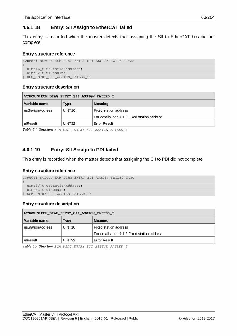
The application interface 63/264
EtherCAT Master V4 | Protocol API DOC150601API05EN | Revision 5 | English | 2017-01 | Released | Public © Hilscher, 2015-2017
4.6.1.18 Entry: SII Assign to EtherCAT failed
This entry is recorded when the master detects that assigning the SII to EtherCAT bus did not complete.
Entry structure reference typedef struct ECM_DIAG_ENTRY_SII_ASSIGN_FAILED_Ttag { uint16_t usStationAddress; uint32_t ulResult; } ECM_ENTRY_SII_ASSIGN_FAILED_T;
Entry structure description
Structure ECM_DIAG_ENTRY_SII_ASSIGN_FAILED_T
Variable name Type Meaning
usStationAddress UINT16 Fixed station address
For details, see 4.1.2 Fixed station address
ulResult UINT32 Error Result
Table 54: Structure ECM_DIAG_ENTRY_SII_ASSIGN_FAILED_T
4.6.1.19 Entry: SII Assign to PDI failed
This entry is recorded when the master detects that assigning the SII to PDI did not complete.
Entry structure reference typedef struct ECM_DIAG_ENTRY_SII_ASSIGN_FAILED_Ttag { uint16_t usStationAddress; uint32_t ulResult; } ECM_ENTRY_SII_ASSIGN_FAILED_T;
Entry structure description
Structure ECM_DIAG_ENTRY_SII_ASSIGN_FAILED_T
Variable name Type Meaning
usStationAddress UINT16 Fixed station address
For details, see 4.1.2 Fixed station address
ulResult UINT32 Error Result
Table 55: Structure ECM_DIAG_ENTRY_SII_ASSIGN_FAILED_T

The application interface 64/264
EtherCAT Master V4 | Protocol API DOC150601API05EN | Revision 5 | English | 2017-01 | Released | Public © Hilscher, 2015-2017
4.6.1.20 Entry: SII Read request failed
This entry is recorded when the master detects when reading an offset within SII failed.
Entry structure reference typedef struct ECM_DIAG_ENTRY_SII_REQUEST_FAILED_Ttag { uint16_t usStationAddress; uint32_t ulSiiWordOffset; uint32_t ulResult; } ECM_ENTRY_SII_REQUEST_FAILED_T;
Entry structure description
Structure ECM_DIAG_ENTRY_SII_REQUEST_FAILED_T
Variable name Type Meaning
usStationAddress UINT16 Fixed station address
For details, see 4.1.2 Fixed station address
ulSiiWordOffset UINT16 Word offset in SII that could not be read.
0 => first word (at byte offset 0)
1 => second word (at byte offset 2)
ulResult UINT32 Error Result
Table 56: Structure ECM_DIAG_ENTRY_SII_REQUEST_FAILED_T

The application interface 65/264
EtherCAT Master V4 | Protocol API DOC150601API05EN | Revision 5 | English | 2017-01 | Released | Public © Hilscher, 2015-2017
4.6.1.21 Entry: Slave warning
This entry is recorded when the master detects certain faults on slaves that are not considered severe but yet worth being noted.
Entry structure reference typedef struct ECM_DIAG_ENTRY_SLAVE_WARNING_Ttag { uint16_t usStationAddress; uint32_t ulWarningType; uint32_t ulWarningParam; } ECM_ENTRY_SII_SLAVE_WARNING_T;
Entry structure description
Structure ECM_DIAG_ENTRY_SLAVE_WARNING_T
Variable name Type Meaning
usStationAddress UINT16 Fixed station address
For details, see 4.1.2 Fixed station address
ulWarningType UINT32 See table below
ulWarningParam UINT32 Meaning depends on ulWarningType
Table 57: Structure ECM_DIAG_ENTRY_SLAVE_WARNING_T
Definition of codes for ulWarningType
Available reason codes for ulWarningType
Value Definition / description
0x0001 ECM_DIAG_ENTRY_SLAVE_WARNING_TYPE_ADVERTISED_64BIT_DC_NOT_WORKING
The slave has the 64bit DC supported flag set in Feature Register but the actual registers only support 32 bit DC.
0x0002 ECM_DIAG_ENTRY_SLAVE_WARNING_TYPE_ADVERTISED_DC_NOT_WORKING
The slave has the DC supported flag set in Feature Register but the DC registers do not work at all.
0x0003 ECM_DIAG_ENTRY_SLAVE_WARNING_TYPE_SLAVE_DID_NOT_ACCEPT_EOE_SET_IP_PARAMS
Slave did not accept EoE SetIpParams request.
ulWarningParam contains the associated error code
Table 58: Available reason codes for ulWarningType

The application interface 66/264
EtherCAT Master V4 | Protocol API DOC150601API05EN | Revision 5 | English | 2017-01 | Released | Public © Hilscher, 2015-2017
4.6.1.22 Entry: Slave error
This entry contains information about errors happening when the master is processing actions on a particular slave.
Entry structure reference typedef struct ECM_DIAG_ENTRY_SLAVE_ERROR_Ttag { uint16_t usStationAddress; uint32_t ulErrorType; uint32_t ulErrorParam; } ECM_ENTRY_SII_SLAVE_ERROR_T;
Entry structure description
Structure ECM_DIAG_ENTRY_SLAVE_ERROR_T
Variable name Type Meaning
usStationAddress UINT16 Fixed station address
For details, see 4.1.2 Fixed station address
ulErrorType UINT32 See table below
ulErrorParam UINT32 Meaning depends on ulErrorType
Table 59: Structure ECM_DIAG_ENTRY_SLAVE_ERROR_T
Definition of codes for ulErrorType
Available reason codes for ulErrorType
Value Definition / description
0x0001 ECM_DIAG_ENTRY_SLAVE_ERROR_TYPE_SYNC_NOT_POSSIBLE_WITHOUT_WORKING_DC
The slave was parameterized to have DC Sync configuration. Yet, the slave does not support the required DC for that.
Table 60: Available reason codes for ulErrorType

The application interface 67/264
EtherCAT Master V4 | Protocol API DOC150601API05EN | Revision 5 | English | 2017-01 | Released | Public © Hilscher, 2015-2017
4.6.2 Reading and clearing diagnostic log entries
4.6.2.1 Read diagnostic log entry service
This packet reads the oldest available entry from the diagnostic log. That entry will be removed from the log. A subsequent read request will read the next entry which has now become the oldest entry.
If there are no entries, the request will return with an error.
For event-based handling, the diagnostic log supports indications. For a description, see 4.6.3 Diagnostic log indication handling.
Packet structure reference typedef struct ECM_IF_READ_DIAG_LOG_ENTRY_REQ_Ttag { TLR_PACKET_HEADER_T tHead; } ECM_IF_READ_DIAG_LOG_ENTRY_REQ_T;
Packet description
Structure ECM_IF_READ_DIAG_LOG_ENTRY_REQ_T Type: Request
Variable Type Value / range Description tHead - Structure TLR_PACKET_HEADER_T
ulDest UINT32 Destination queue-handle ulSrc UINT32 Source queue-handle ulDestId UINT32 Destination End Point Identifier, specifying the final receiver of the
packet within the Destination Process. Set to 0 for the Initialization Packet
ulSrcId UINT32 Source End Point Identifier, specifying the origin of the packet inside the Source Process
ulLen UINT32 0 Packet Data Length in bytes ulId UINT32 0 ... 232-1 Packet Identification as unique number generated by the Source
Process of the Packet ulSta UINT32 See section Status/Error codes overview ulCmd UINT32 0x9E30 ECM_IF_CMD_READ_DIAG_LOG_ENTRY_REQ - Command
ulExt UINT32 0 Extension, reserved ulRout UINT32 x Routing, do not touch
Table 61: ECM_IF_CMD_READ_DIAG_LOG_ENTRY_REQ – Read diagnostic log entry service
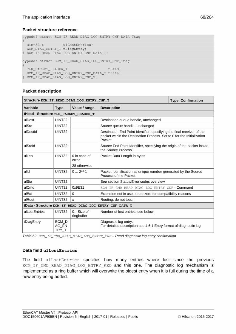
The application interface 68/264
EtherCAT Master V4 | Protocol API DOC150601API05EN | Revision 5 | English | 2017-01 | Released | Public © Hilscher, 2015-2017
Packet structure reference typedef struct ECM_IF_READ_DIAG_LOG_ENTRY_CNF_DATA_Ttag { uint32_t ulLostEntries; ECM_DIAG_ENTRY_T tDiagEntry; } ECM_IF_READ_DIAG_LOG_ENTRY_CNF_DATA_T; typedef struct ECM_IF_READ_DIAG_LOG_ENTRY_CNF_Ttag { TLR_PACKET_HEADER_T tHead; ECM_IF_READ_DIAG_LOG_ENTRY_CNF_DATA_T tData; } ECM_IF_READ_DIAG_LOG_ENTRY_CNF_T;
Packet description
Structure ECM_IF_READ_DIAG_LOG_ENTRY_CNF_T Type: Confirmation
Variable Type Value / range Description tHead - Structure TLR_PACKET_HEADER_T ulDest UINT32 Destination queue handle, unchanged ulSrc UINT32 Source queue handle, unchanged ulDestId UINT32 Destination End Point Identifier, specifying the final receiver of the
packet within the Destination Process. Set to 0 for the Initialization Packet
ulSrcId UINT32 Source End Point Identifier, specifying the origin of the packet inside the Source Process
ulLen UINT32 0 in case of error 28 otherwise
Packet Data Length in bytes
ulId UINT32 0 ... 232-1 Packet Identification as unique number generated by the Source Process of the Packet
ulSta UINT32 See section Status/Error codes overview ulCmd UINT32 0x9E31 ECM_IF_CMD_READ_DIAG_LOG_ENTRY_CNF - Command
ulExt UINT32 0 Extension not in use, set to zero for compatibility reasons ulRout UINT32 x Routing, do not touch tData - Structure ECM_IF_READ_DIAG_LOG_ENTRY_CNF_DATA_T ulLostEntries UINT32 0…Size of
ringbuffer Number of lost entries, see below
tDiagEntry ECM_DIAG_ENTRY_T
Diagnostic log entry. For detailed description see 4.6.1 Entry format of diagnostic log
Table 62: ECM_IF_CMD_READ_DIAG_LOG_ENTRY_CNF – Read diagnostic log entry confirmation
Data field ulLostEntries
The field ulLostEntries specifies how many entries where lost since the previous ECM_IF_CMD_READ_DIAG_LOG_ENTRY_REQ and this one. The diagnostic log mechanism is implemented as a ring buffer which will overwrite the oldest entry when it is full during the time of a new entry being added.

The application interface 69/264
EtherCAT Master V4 | Protocol API DOC150601API05EN | Revision 5 | English | 2017-01 | Released | Public © Hilscher, 2015-2017
4.6.2.2 Clear diagnostic log entry
This service clears the diagnostic log. If an application is restarted, it may be helpful to clear the diagnostic log. Otherwise, the application may read out entries that have no relevance anymore.
Packet structure reference typedef struct ECM_IF_CLEAR_DIAG_LOG_REQ_Ttag { TLR_PACKET_HEADER_T tHead; } ECM_IF_CLEAR_DIAG_LOG_REQ_T;
Packet description
Structure ECM_IF_CLEAR_DIAG_LOG_REQ_T Type: Request
Variable Type Value / range Description tHead - Structure TLR_PACKET_HEADER_T ulDest UINT32 Destination queue-handle ulSrc UINT32 Source queue-handle ulDestId UINT32 Destination End Point Identifier, specifying the final receiver of the
packet within the Destination Process. Set to 0 for the Initialization Packet
ulSrcId UINT32 Source End Point Identifier, specifying the origin of the packet inside the Source Process
ulLen UINT32 0 Packet Data Length in bytes ulId UINT32 0 ... 232-1 Packet Identification as unique number generated by the Source
Process of the Packet ulSta UINT32 See section Status/Error codes overview ulCmd UINT32 0x9E32 ECM_IF_CMD_CLEAR_DIAG_LOG_REQ - Command
ulExt UINT32 0 Extension, reserved ulRout UINT32 x Routing, do not touch
Table 63: ECM_IF_CMD_CLEAR_DIAG_LOG_REQ –Clear diagnostic log request

The application interface 70/264
EtherCAT Master V4 | Protocol API DOC150601API05EN | Revision 5 | English | 2017-01 | Released | Public © Hilscher, 2015-2017
Packet structure reference typedef struct ECM_IF_CLEAR_DIAG_LOG_CNF_Ttag { TLR_PACKET_HEADER_T tHead; } ECM_IF_CLEAR_DIAG_LOG_CNF_T;
Packet description
Structure ECM_IF_CLEAR_DIAG_LOG_CNF_T Type: Confirmation
Variable Type Value / range Description tHead - Structure TLR_PACKET_HEADER_T
ulDest UINT32 Destination queue handle, unchanged ulSrc UINT32 Source queue handle, unchanged ulDestId UINT32 Destination End Point Identifier, specifying the final receiver of the
packet within the Destination Process. Set to 0 for the Initialization Packet
ulSrcId UINT32 Source End Point Identifier, specifying the origin of the packet inside the Source Process
ulLen UINT32 0 Packet Data Length in bytes ulId UINT32 0 ... 232-1 Packet Identification as unique number generated by the Source
Process of the Packet ulSta UINT32 See section Status/Error codes overview ulCmd UINT32 0x9E33 ECM_IF_CMD_CLEAR_DIAG_LOG_CNF - Command
ulExt UINT32 0 Extension not in use, set to zero for compatibility reasons ulRout UINT32 x Routing, do not touch
Table 64: ECM_IF_CMD_CLEAR_DIAG_LOG_CNF – Clear diagnostic log confirmation

The application interface 71/264
EtherCAT Master V4 | Protocol API DOC150601API05EN | Revision 5 | English | 2017-01 | Released | Public © Hilscher, 2015-2017
4.6.3 Diagnostic log indication handling This chapter will first outline the handling of the diagnostic log indications. Afterwards, the packets will be described.
The main purpose of the diagnostic log is to provide a history of EtherCAT or master specific events. This extends the diagnosis capabilities. In addition, the diagnostic log can be used for diagnosing network boot up problems.
Note: As the diagnostic log is an asynchronously handled queue with respect to the master state machines, the reasons why the event happened may not exist anymore at the time of the read out.

The application interface 72/264
EtherCAT Master V4 | Protocol API DOC150601API05EN | Revision 5 | English | 2017-01 | Released | Public © Hilscher, 2015-2017
4.6.3.1 Flow diagram of handling of diagnostic log indications
Figure 3: Flow diagram diagnostic log indications handling
The diagnostic log indications provide the current count of entry in the diagnostic log. Therefore, a state machine, handling the read out, must be able to reset the diagnostic log entry count as shown in the flow diagram.
Step read diagnostic log entry
This step includes presenting and/or dealing with the diagnostic log entry when the request has been successful. The decisions taken on the diagnostic log are up to the application. However, the read out is asynchronous to the state machine in the master. Therefore, the actual reason for the event may not be valid anymore.

The application interface 73/264
EtherCAT Master V4 | Protocol API DOC150601API05EN | Revision 5 | English | 2017-01 | Released | Public © Hilscher, 2015-2017
4.6.3.2 Register for diagnostic log indications service
This packet registers an application task for receiving indications that new diagnostic entries are available in the diagnostic log.
The following status indication will be sent to the application task after successful registration:
4.6.3.4 New diagnostic log entries available indication
If the application does not want to receive those indications anymore, it has to use the 4.6.3.3 Unregister from diagnostic log indications .
Packet structure reference typedef struct ECM_IF_DIAG_LOG_INDICATIONS_REGISTER_REQ_Ttag { TLR_PACKET_HEADER_T tHead; } ECM_IF_DIAG_LOG_INDICATIONS_REGISTER_REQ_T;
Packet description
Structure ECM_IF_DIAG_LOG_INDICATIONS_REGISTER_REQ_T Type: Request
Variable Type Value / range Description tHead - Structure TLR_PACKET_HEADER_T
ulDest UINT32 Destination queue-handle ulSrc UINT32 Source queue-handle ulDestId UINT32 Destination End Point Identifier, specifying the final receiver of the
packet within the Destination Process. Set to 0 for the Initialization Packet
ulSrcId UINT32 Source End Point Identifier, specifying the origin of the packet inside the Source Process
ulLen UINT32 0 Packet Data Length in bytes ulId UINT32 0 ... 232-1 Packet Identification as unique number generated by the Source
Process of the Packet ulSta UINT32 See section Status/Error codes overview ulCmd UINT32 0x9E36 ECM_IF_CMD_DIAG_LOG_INDICATIONS_REGISTER_REQ -
Command
ulExt UINT32 0 Extension, reserved ulRout UINT32 x Routing, do not touch
Table 65: ECM_IF_CMD_DIAG_LOG_INDICATIONS_REGISTER_REQ – Register for diagnostic log indications request
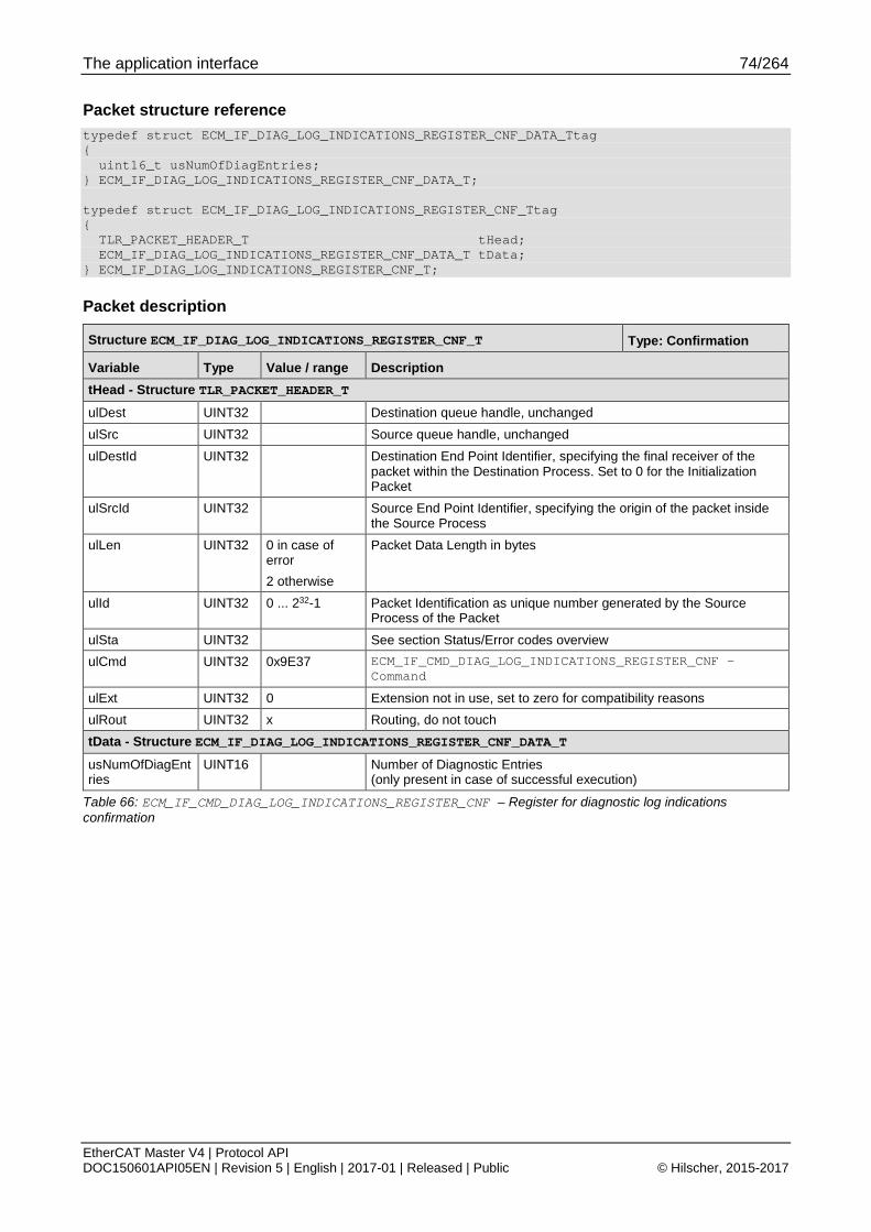
The application interface 74/264
EtherCAT Master V4 | Protocol API DOC150601API05EN | Revision 5 | English | 2017-01 | Released | Public © Hilscher, 2015-2017
Packet structure reference typedef struct ECM_IF_DIAG_LOG_INDICATIONS_REGISTER_CNF_DATA_Ttag { uint16_t usNumOfDiagEntries; } ECM_IF_DIAG_LOG_INDICATIONS_REGISTER_CNF_DATA_T; typedef struct ECM_IF_DIAG_LOG_INDICATIONS_REGISTER_CNF_Ttag { TLR_PACKET_HEADER_T tHead; ECM_IF_DIAG_LOG_INDICATIONS_REGISTER_CNF_DATA_T tData; } ECM_IF_DIAG_LOG_INDICATIONS_REGISTER_CNF_T;
Packet description
Structure ECM_IF_DIAG_LOG_INDICATIONS_REGISTER_CNF_T Type: Confirmation
Variable Type Value / range Description tHead - Structure TLR_PACKET_HEADER_T ulDest UINT32 Destination queue handle, unchanged ulSrc UINT32 Source queue handle, unchanged ulDestId UINT32 Destination End Point Identifier, specifying the final receiver of the
packet within the Destination Process. Set to 0 for the Initialization Packet
ulSrcId UINT32 Source End Point Identifier, specifying the origin of the packet inside the Source Process
ulLen UINT32 0 in case of error 2 otherwise
Packet Data Length in bytes
ulId UINT32 0 ... 232-1 Packet Identification as unique number generated by the Source Process of the Packet
ulSta UINT32 See section Status/Error codes overview ulCmd UINT32 0x9E37 ECM_IF_CMD_DIAG_LOG_INDICATIONS_REGISTER_CNF -
Command
ulExt UINT32 0 Extension not in use, set to zero for compatibility reasons ulRout UINT32 x Routing, do not touch tData - Structure ECM_IF_DIAG_LOG_INDICATIONS_REGISTER_CNF_DATA_T
usNumOfDiagEntries
UINT16 Number of Diagnostic Entries (only present in case of successful execution)
Table 66: ECM_IF_CMD_DIAG_LOG_INDICATIONS_REGISTER_CNF – Register for diagnostic log indications confirmation

The application interface 75/264
EtherCAT Master V4 | Protocol API DOC150601API05EN | Revision 5 | English | 2017-01 | Released | Public © Hilscher, 2015-2017
4.6.3.3 Unregister from diagnostic log indications service
This packet deregisters an application task from receiving diagnostic indications.
The following diagnostic indications will not be sent anymore to the application after successful deregistration:
4.6.3.4 New diagnostic log entries available indication
Packet structure reference typedef struct ECM_IF_DIAG_LOG_INDICATIONS_UNREGISTER_REQ_Ttag { TLR_PACKET_HEADER_T tHead; } ECM_IF_DIAG_LOG_INDICATIONS_UNREGISTER_REQ_T;
Packet description
Structure ECM_IF_DIAG_LOG_INDICATIONS_UNREGISTER_REQ_T Type: Request
Variable Type Value / range Description tHead - Structure TLR_PACKET_HEADER_T ulDest UINT32 Destination queue-handle ulSrc UINT32 Source queue-handle ulDestId UINT32 Destination End Point Identifier, specifying the final receiver of the
packet within the Destination Process. Set to 0 for the Initialization Packet
ulSrcId UINT32 Source End Point Identifier, specifying the origin of the packet inside the Source Process
ulLen UINT32 0 Packet Data Length in bytes ulId UINT32 0 ... 232-1 Packet Identification as unique number generated by the Source
Process of the Packet ulSta UINT32 See section Status/Error codes overview ulCmd UINT32 0x9E38 ECM_IF_CMD_DIAG_LOG_INDICATIONS_UNREGISTER_REQ -
Command ulExt UINT32 0 Extension, reserved ulRout UINT32 x Routing, do not touch
Table 67: ECM_IF_CMD_DIAG_LOG_INDICATIONS_UNREGISTER_REQ – Unregister from diagnostic log indications request

The application interface 76/264
EtherCAT Master V4 | Protocol API DOC150601API05EN | Revision 5 | English | 2017-01 | Released | Public © Hilscher, 2015-2017
Packet structure reference typedef struct ECM_IF_DIAG_LOG_INDICATIONS_UNREGISTER_CNF_Ttag { TLR_PACKET_HEADER_T tHead; } ECM_IF_DIAG_LOG_INDICATIONS_UNREGISTER_CNF_T;
Packet description
Structure ECM_IF_DIAG_LOG_INDICATIONS_UNREGISTER_CNF_T Type: Confirmation
Variable Type Value / range Description tHead - Structure TLR_PACKET_HEADER_T
ulDest UINT32 Destination queue handle, unchanged ulSrc UINT32 Source queue handle, unchanged ulDestId UINT32 Destination End Point Identifier, specifying the final receiver of the
packet within the Destination Process. Set to 0 for the Initialization Packet
ulSrcId UINT32 Source End Point Identifier, specifying the origin of the packet inside the Source Process
ulLen UINT32 0 Packet Data Length in bytes ulId UINT32 0 ... 232-1 Packet Identification as unique number generated by the Source
Process of the Packet ulSta UINT32 See section Status/Error codes overview ulCmd UINT32 0x9E39 ECM_IF_CMD_DIAG_LOG_INDICATIONS_UNREGISTER_CNF -
Command ulExt UINT32 0 Extension not in use, set to zero for compatibility reasons ulRout UINT32 x Routing, do not touch
Table 68: ECM_IF_CMD_DIAG_LOG_INDICATIONS_UNREGISTER_CNF - Unregister from diagnostic log indications confirmation

The application interface 77/264
EtherCAT Master V4 | Protocol API DOC150601API05EN | Revision 5 | English | 2017-01 | Released | Public © Hilscher, 2015-2017
4.6.3.4 New diagnostic log entries available indication
This indication is sent every time a new diagnostic log entry is available if the application has previously been registered for this service using the 4.6.3.2 Register for diagnostic log indications service.
The parameter usNumOfDiagEntries contains the number of new entries in the log which can subsequently be read out using the 4.6.2.1 Read diagnostic log entry service.
Packet structure reference typedef _struct ECM_IF_NEW_DIAG_LOG_ENTRIES_IND_DATA_Ttag { uint16_t usNumOfDiagEntries; } ECM_IF_NEW_DIAG_LOG_ENTRIES_IND_DATA_T; typedef struct ECM_IF_NEW_DIAG_LOG_ENTRIES_IND_Ttag { TLR_PACKET_HEADER_T tHead; ECM_IF_NEW_DIAG_LOG_ENTRIES_IND_DATA_T tData; } ECM_IF_NEW_DIAG_LOG_ENTRIES_IND_T;
Packet description
Structure ECM_IF_NEW_DIAG_LOG_ENTRIES_IND_T Type: Indication
Variable Type Value / range Description tHead - Structure TLR_PACKET_HEADER_T
ulDest UINT32 Destination queue-handle ulSrc UINT32 Source queue-handle ulDestId UINT32 Destination End Point Identifier, specifying the final receiver of the
packet within the Destination Process. Set to 0 for the Initialization Packet
ulSrcId UINT32 Source End Point Identifier, specifying the origin of the packet inside the Source Process
ulLen UINT32 2 Packet Data Length in bytes ulId UINT32 0 ... 232-1 Packet Identification as unique number generated by the Source
Process of the Packet ulSta UINT32 See section Status/Error codes overview ulCmd UINT32 0x9E34 ECM_IF_CMD_NEW_DIAG_LOG_ENTRIES_IND - Command
ulExt UINT32 0 Extension, reserved ulRout UINT32 x Routing, do not touch tData - Structure ECM_IF_NEW_DIAG_LOG_ENTRIES_IND_DATA_T usNumOfDiagEntries
UINT16 Number of diagnostic entries
Table 69: ECM_IF_CMD_NEW_DIAG_LOG_ENTRIES_IND – New diagnostic log entries available indication

The application interface 78/264
EtherCAT Master V4 | Protocol API DOC150601API05EN | Revision 5 | English | 2017-01 | Released | Public © Hilscher, 2015-2017
Packet structure reference typedef struct ECM_IF_NEW_DIAG_LOG_ENTRIES_RES_Ttag { TLR_PACKET_HEADER_T tHead; } ECM_IF_NEW_DIAG_LOG_ENTRIES_RES_T;
Packet description
Structure ECM_IF_NEW_DIAG_LOG_ENTRIES_RES_T Type: Response
Variable Type Value / range Description tHead - Structure TLR_PACKET_HEADER_T
ulDest UINT32 Destination queue handle, unchanged ulSrc UINT32 Source queue handle, unchanged ulDestId UINT32 Destination End Point Identifier, specifying the final receiver of the
packet within the Destination Process. Set to 0 for the Initialization Packet
ulSrcId UINT32 Source End Point Identifier, specifying the origin of the packet inside the Source Process
ulLen UINT32 0 Packet Data Length in bytes ulId UINT32 0 ... 232-1 Packet Identification as unique number generated by the Source
Process of the Packet ulSta UINT32 See section Status/Error codes overview ulCmd UINT32 0x9E35 ECM_IF_CMD_NEW_DIAG_LOG_ENTRIES_RES - Command
ulExt UINT32 0 Extension not in use, set to zero for compatibility reasons ulRout UINT32 x Routing, do not touch
Table 70: ECM_IF_CMD_NEW_DIAG_LOG_ENTRIES_RES – New diagnostic log entries available response

The application interface 79/264
EtherCAT Master V4 | Protocol API DOC150601API05EN | Revision 5 | English | 2017-01 | Released | Public © Hilscher, 2015-2017
4.7 CoE services CoE services includes the following services if supported by slave:
SDO access (data)
SDOINFO access (structure info, not all slaves)
4.7.1 Slave state accessibility CoE access is possible in the following slave states if supported by slave:
PREOP
SAFEOP
OP
Slaves may limit access depending on slave state to certain objects.
4.7.2 SDO access
4.7.2.1 Fragmentation of download/write SDO
Flow charts are presented in chapter 4.7.2.5 SDO fragmentation flowcharts.
When the data fits into a single fragment, the following sequence is used:
Figure 4: Single fragment handling of download/write SDO Service

The application interface 80/264
EtherCAT Master V4 | Protocol API DOC150601API05EN | Revision 5 | English | 2017-01 | Released | Public © Hilscher, 2015-2017
When two or more fragments are required for the transfer, the following sequence diagrams apply:
Figure 5: Two fragment handling of download/write SDO Service
Figure 6: Multiple fragment handling of download/write SDO Service

The application interface 81/264
EtherCAT Master V4 | Protocol API DOC150601API05EN | Revision 5 | English | 2017-01 | Released | Public © Hilscher, 2015-2017
4.7.2.2 Fragmentation of upload/read SDO
Flow charts are presented in chapter 4.7.2.5 SDO fragmentation flowcharts.
When the data fit into a single fragment, the following sequence is used:
Figure 7: Single fragment handling of upload/read SDO Service
When two or more fragments are required for the transfer, the following sequence diagrams apply:
Figure 8: Two fragment handling of upload/read SDO Service

The application interface 82/264
EtherCAT Master V4 | Protocol API DOC150601API05EN | Revision 5 | English | 2017-01 | Released | Public © Hilscher, 2015-2017
Figure 9: Multiple fragment handling of upload/read SDO Service

The application interface 83/264
EtherCAT Master V4 | Protocol API DOC150601API05EN | Revision 5 | English | 2017-01 | Released | Public © Hilscher, 2015-2017
4.7.2.3 Download/write SDO
This packet allows writing to an object/ subobject. It supports complete access and fragmentation.
The following addressing schemes are used:
During generic bus scan, use 4.1.3 Topology position
During normal operation, use 4.1.2 Fixed station address
ulDestId has to be handled as follows:
First fragment has ulDestId == 0
Stack returns first fragment confirmation with ulDestId != 0
This ulDestId has to be provided to all subsequent fragments
Packet structure reference typedef struct ECM_IF_COE_SDO_DOWNLOAD_REQ_DATA_Ttag { uint16_t usStationAddress; uint16_t usTransportType; uint16_t usAoEPort; uint16_t usObjIndex; uint8_t bSubIndex; uint8_t fCompleteAccess; uint32_t ulTotalBytes; uint32_t ulTimeoutMs; uint8_t abData[1024]; } ECM_IF_COE_SDO_DOWNLOAD_REQ_DATA_T; typedef struct ECM_IF_COE_SDO_DOWNLOAD_REQ_Ttag { TLR_PACKET_HEADER_T tHead; ECM_IF_COE_SDO_DOWNLOAD_REQ_DATA_T tData; } ECM_IF_COE_SDO_DOWNLOAD_REQ_T;

The application interface 84/264
EtherCAT Master V4 | Protocol API DOC150601API05EN | Revision 5 | English | 2017-01 | Released | Public © Hilscher, 2015-2017
Packet description
Structure ECM_IF_COE_SDO_DOWNLOAD_REQ_T Type: Request
Variable Type Value / range Description tHead - Structure TLR_PACKET_HEADER_T ulDest UINT32 Destination queue-handle ulSrc UINT32 Source queue-handle ulDestId UINT32 Destination End Point Identifier, specifying the final receiver of the
packet within the Destination Process. Set to 0 for the Initialization Packet
ulSrcId UINT32 Source End Point Identifier, specifying the origin of the packet inside the Source Process
ulLen UINT32 18 + n Packet Data Length in bytes ulId UINT32 0 ... 232-1 Packet Identification as unique number generated by the Source
Process of the Packet ulSta UINT32 See section Status/Error codes overview ulCmd UINT32 0x9A00 ECM_IF_CMD_COE_SDO_DOWNLOAD_REQ - Command
ulExt UINT32 0 Extension not in use, set to zero for compatibility reasons ulRout UINT32 X Routing, do not touch
tData – Structure ECM_IF_COE_SDO_DOWNLOAD_REQ_DATA_T usStationAddress UINT16 Valid
address During bus scan, use 4.1.3 Topology position During normal operation, use 4.1.2 Fixed station address
usTransportType UINT16 0,1 Transport type 0: CoE transport (ECM_IF_COE_TRANSPORT_COE), 1: AoE transport (ECM_IF_COE_TRANSPORT_AOE)
usAoEPort UINT16 0…65535 AoEPort (only used if usTransportType = 1) usObjIndex UINT16 0…65535 Index of the object bSubIndex UINT8 0 … 255
0 … 1 If a single subindex is requested, it refers to its subindex If complete access, it defines the start sub index
fCompleteAccess BOOL TRUE, FALSE
If TRUE, complete access is requested If FALSE, a single subindex is accessed
ulTotalBytes UINT32 0 ... 232-1 Summed length of all abData of all fragments
ulTimeoutMs UINT32 Timeout in ms abData[n] UINT8[] Data of a fragment. Actual byte length is given as ulLen - 18
Table 71: ECM_IF_CMD_COE_SDO_DOWNLOAD_REQ – Download/write SDO request
Timeout value ulTimeoutMs
It is recommended to use at least 1000 ms as value. However, slaves exist that need higher timeout value due to their way of functioning.

The application interface 85/264
EtherCAT Master V4 | Protocol API DOC150601API05EN | Revision 5 | English | 2017-01 | Released | Public © Hilscher, 2015-2017
Packet structure reference typedef struct ECM_IF_COE_SDO_DOWNLOAD_CNF_DATA_Ttag { uint16_t usStationAddress; uint16_t usTransportType; uint16_t usAoEPort; uint16_t usObjIndex; uint8_t bSubIndex; uint8_t fCompleteAccess; uint32_t ulTotalBytes; uint32_t ulTimeoutMs; } ECM_IF_COE_SDO_DOWNLOAD_CNF_DATA_T; typedef struct ECM_IF_COE_SDO_DOWNLOAD_CNF_Ttag { TLR_PACKET_HEADER_T tHead; ECM_IF_COE_SDO_DOWNLOAD_CNF_DATA_T tData; } ECM_IF_COE_SDO_DOWNLOAD_CNF_T;
Packet description
Structure ECM_IF_COE_SDO_DOWNLOAD_CNF_T Type: Confirmation
Variable Type Value / range Description tHead - Structure TLR_PACKET_HEADER_T ulDest UINT32 Destination queue handle, unchanged ulSrc UINT32 Source queue handle, unchanged ulDestId UINT32 Destination End Point Identifier, specifying the final receiver of the packet
within the Destination Process. Set to 0 for the Initialization Packet
ulSrcId UINT32 Source End Point Identifier, specifying the origin of the packet inside the Source Process
ulLen UINT32 18 Packet Data Length in bytes ulId UINT32 0 ... 232-1 Packet Identification, unchanged ulSta UINT32 See section Status/Error codes overview ulCmd UINT32 0x9A01 ECM_IF_CMD_COE_SDO_DOWNLOAD_CNF – Command
ulExt UINT32 0 Extension, reserved ulRout UINT32 x Routing information, do not change
tData – Structure ECM_IF_COE_SDO_DOWNLOAD_CNF_DATA_T usStationAddress
UINT16 Valid address Value from request
usTransportType
UINT16 0,1 Value from request
usAoEPort UINT16 Value from request usObjIndex UINT16 0…65535 Value from request bSubIndex UINT8 0 … 255 Value from request
fCompleteAccess
BOOL TRUE, FALSE
Value from request
ulTotalBytes UINT32 Value from request ulTimeoutMs UINT32 Value from request
Table 72: ECM_IF_CMD_COE_SDO_DOWNLOAD_CNF – Download/write SDO confirmation
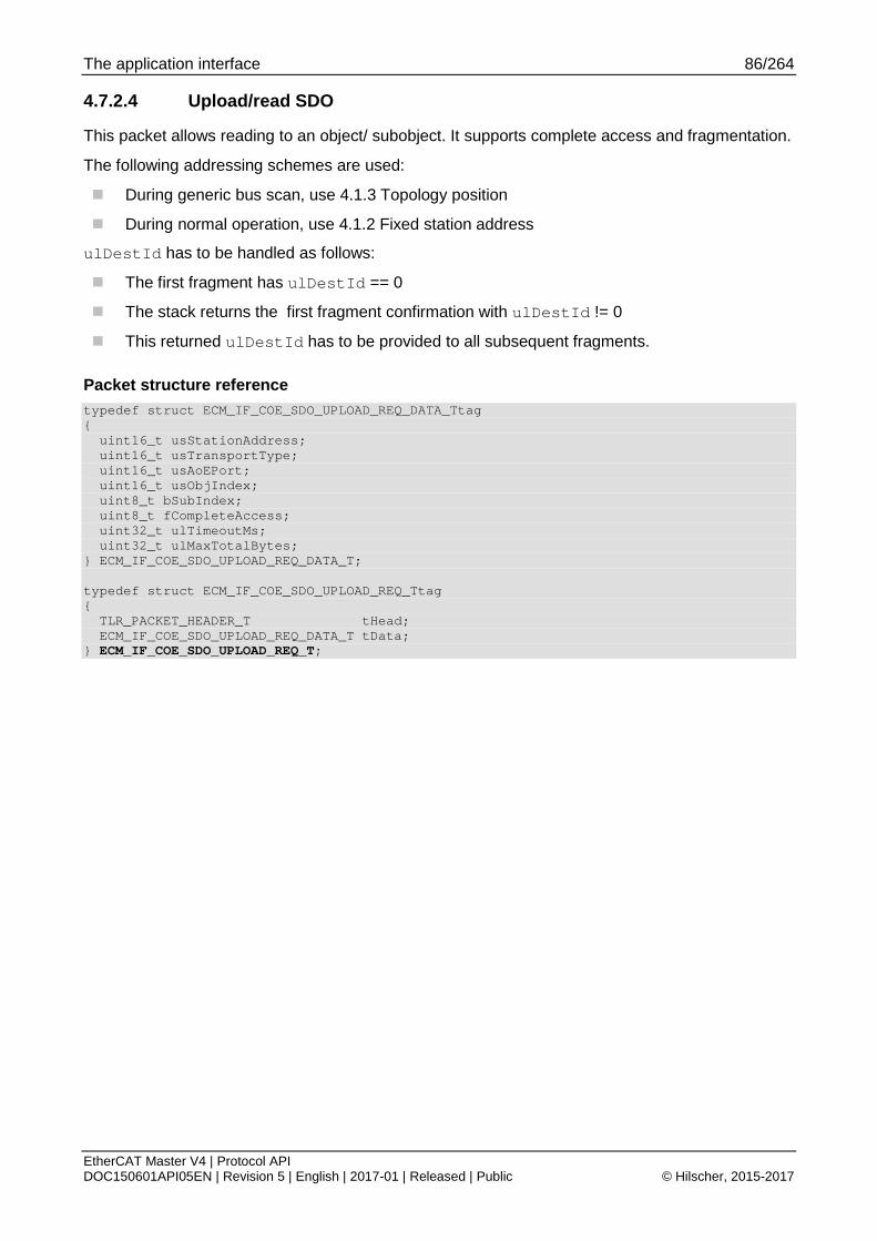
The application interface 86/264
EtherCAT Master V4 | Protocol API DOC150601API05EN | Revision 5 | English | 2017-01 | Released | Public © Hilscher, 2015-2017
4.7.2.4 Upload/read SDO
This packet allows reading to an object/ subobject. It supports complete access and fragmentation.
The following addressing schemes are used:
During generic bus scan, use 4.1.3 Topology position
During normal operation, use 4.1.2 Fixed station address
ulDestId has to be handled as follows:
The first fragment has ulDestId == 0
The stack returns the first fragment confirmation with ulDestId != 0
This returned ulDestId has to be provided to all subsequent fragments.
Packet structure reference typedef struct ECM_IF_COE_SDO_UPLOAD_REQ_DATA_Ttag { uint16_t usStationAddress; uint16_t usTransportType; uint16_t usAoEPort; uint16_t usObjIndex; uint8_t bSubIndex; uint8_t fCompleteAccess; uint32_t ulTimeoutMs; uint32_t ulMaxTotalBytes; } ECM_IF_COE_SDO_UPLOAD_REQ_DATA_T; typedef struct ECM_IF_COE_SDO_UPLOAD_REQ_Ttag { TLR_PACKET_HEADER_T tHead; ECM_IF_COE_SDO_UPLOAD_REQ_DATA_T tData; } ECM_IF_COE_SDO_UPLOAD_REQ_T;
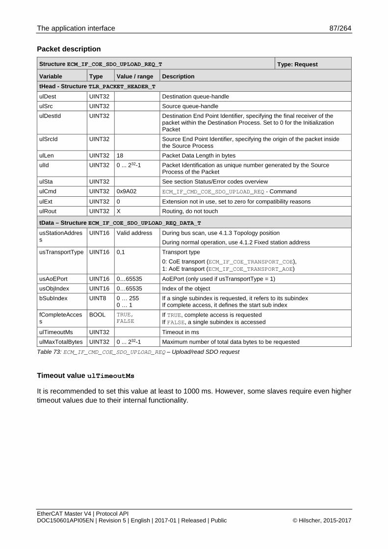
The application interface 87/264
EtherCAT Master V4 | Protocol API DOC150601API05EN | Revision 5 | English | 2017-01 | Released | Public © Hilscher, 2015-2017
Packet description
Structure ECM_IF_COE_SDO_UPLOAD_REQ_T Type: Request
Variable Type Value / range Description tHead - Structure TLR_PACKET_HEADER_T ulDest UINT32 Destination queue-handle ulSrc UINT32 Source queue-handle ulDestId UINT32 Destination End Point Identifier, specifying the final receiver of the
packet within the Destination Process. Set to 0 for the Initialization Packet
ulSrcId UINT32 Source End Point Identifier, specifying the origin of the packet inside the Source Process
ulLen UINT32 18 Packet Data Length in bytes ulId UINT32 0 ... 232-1 Packet Identification as unique number generated by the Source
Process of the Packet ulSta UINT32 See section Status/Error codes overview ulCmd UINT32 0x9A02 ECM_IF_CMD_COE_SDO_UPLOAD_REQ - Command
ulExt UINT32 0 Extension not in use, set to zero for compatibility reasons ulRout UINT32 X Routing, do not touch
tData – Structure ECM_IF_COE_SDO_UPLOAD_REQ_DATA_T usStationAddress
UINT16 Valid address During bus scan, use 4.1.3 Topology position During normal operation, use 4.1.2 Fixed station address
usTransportType UINT16 0,1 Transport type 0: CoE transport (ECM_IF_COE_TRANSPORT_COE), 1: AoE transport (ECM_IF_COE_TRANSPORT_AOE)
usAoEPort UINT16 0…65535 AoEPort (only used if usTransportType = 1) usObjIndex UINT16 0…65535 Index of the object bSubIndex UINT8 0 … 255
0 … 1 If a single subindex is requested, it refers to its subindex If complete access, it defines the start sub index
fCompleteAccess
BOOL TRUE, FALSE
If TRUE, complete access is requested If FALSE, a single subindex is accessed
ulTimeoutMs UINT32 Timeout in ms ulMaxTotalBytes UINT32 0 ... 232-1 Maximum number of total data bytes to be requested
Table 73: ECM_IF_CMD_COE_SDO_UPLOAD_REQ – Upload/read SDO request
Timeout value ulTimeoutMs
It is recommended to set this value at least to 1000 ms. However, some slaves require even higher timeout values due to their internal functionality.

The application interface 88/264
EtherCAT Master V4 | Protocol API DOC150601API05EN | Revision 5 | English | 2017-01 | Released | Public © Hilscher, 2015-2017
Packet structure reference typedef struct ECM_IF_COE_SDO_UPLOAD_CNF_DATA_Ttag { uint16_t usStationAddress; uint16_t usTransportType; uint16_t usAoEPort; uint16_t usObjIndex; uint8_t bSubIndex; uint8_t fCompleteAccess; uint32_t ulTimeoutMs; uint32_t ulTotalBytes; uint8_t abData[1024]; } ECM_IF_COE_SDO_UPLOAD_CNF_DATA_T; typedef struct ECM_IF_COE_SDO_UPLOAD_CNF_Ttag { TLR_PACKET_HEADER_T tHead; ECM_IF_COE_SDO_UPLOAD_CNF_DATA_T tData; } ECM_IF_COE_SDO_UPLOAD_CNF_T;
Packet description
Structure ECM_IF_COE_SDO_UPLOAD_CNF_T Type: Confirmation
Variable Type Value / range Description tHead - Structure TLR_PACKET_HEADER_T ulDest UINT32 Destination queue handle, unchanged ulSrc UINT32 Source queue handle, unchanged ulDestId UINT32 Destination End Point Identifier, specifying the final receiver of the packet
within the Destination Process. Set to 0 for the Initialization Packet ulSrcId UINT32 Source End Point Identifier, specifying the origin of the packet inside the
Source Process ulLen UINT32 18 + n Packet Data Length in bytes ulId UINT32 0 ... 232-1 Packet Identification, unchanged ulSta UINT32 See section Status/Error codes overview ulCmd UINT32 0x9A03 ECM_IF_CMD_COE_SDO_UPLOAD_CNF – Command
ulExt UINT32 0 Extension, reserved ulRout UINT32 x Routing information, do not change
tData – Structure ECM_IF_COE_SDO_UPLOAD_CNF_DATA_T usStationAddress
UINT16 Valid address Value from request
usTransportType
UINT16 0,1 Value from request
usAoEPort UINT16 Value from request usObjIndex UINT16 Value from request bSubIndex UINT8 0 … 255 Value from request fCompleteAccess
BOOL TRUE, FALSE
Value from request
ulTimeoutMs UINT32 Timeout in ms ulTotalBytes UINT32 Summed length of all abData of all fragments abData[n] UINT8[] Data of a fragment. Actual byte length is given as ulLen - 18
Table 74: ECM_IF_CMD_COE_SDO_UPLOAD_CNF – Upload/read SDO confirmation

The application interface 89/264
EtherCAT Master V4 | Protocol API DOC150601API05EN | Revision 5 | English | 2017-01 | Released | Public © Hilscher, 2015-2017
4.7.2.5 SDO fragmentation flowcharts
Figure 10: Flowchart for download / write SDO fragmentation

The application interface 90/264
EtherCAT Master V4 | Protocol API DOC150601API05EN | Revision 5 | English | 2017-01 | Released | Public © Hilscher, 2015-2017
Figure 11: Flowchart for upload/ read SDO Fragmentation

The application interface 91/264
EtherCAT Master V4 | Protocol API DOC150601API05EN | Revision 5 | English | 2017-01 | Released | Public © Hilscher, 2015-2017
4.7.3 SDOINFO access
4.7.3.1 Fragmentation of SDOINFO.GetOdList
Flow charts are presented in chapter 4.7.3.7 SDOINFO fragmentation flowcharts.
When the data fit into a single fragment, the following sequence is used:
Figure 12: Single fragment handling of GetOdList SDOINFO service
When two or more fragments are required for the transfer, the following sequence diagrams apply:
Figure 13: Two fragment handling of GetOdList SDOINFO service

The application interface 92/264
EtherCAT Master V4 | Protocol API DOC150601API05EN | Revision 5 | English | 2017-01 | Released | Public © Hilscher, 2015-2017
Figure 14: Multiple fragment handling of GetOdList SDOINFO service

The application interface 93/264
EtherCAT Master V4 | Protocol API DOC150601API05EN | Revision 5 | English | 2017-01 | Released | Public © Hilscher, 2015-2017
4.7.3.2 Fragmentation of SDOINFO.GetObjDesc
Flow charts are presented in chapter 4.7.3.7 SDOINFO fragmentation flowcharts.
When the data fit into a single fragment, the following sequence is used:
Figure 15: Single fragment handling of GetObjDesc SDOINFO Service
When two or more fragments are required for the transfer, the following sequence diagrams apply:
Figure 16: Two fragment handling of GetObjDesc SDOINFO Service

The application interface 94/264
EtherCAT Master V4 | Protocol API DOC150601API05EN | Revision 5 | English | 2017-01 | Released | Public © Hilscher, 2015-2017
Figure 17: Multiple fragment handling of GetObjDesc SDOINFO Service

The application interface 95/264
EtherCAT Master V4 | Protocol API DOC150601API05EN | Revision 5 | English | 2017-01 | Released | Public © Hilscher, 2015-2017
4.7.3.3 Fragmentation of SDOINFO.GetEntryDesc
Flow charts are presented in chapter 4.7.3.7 SDOINFO fragmentation flowcharts.
When the data fit into a single fragment, the following sequence is used:
Figure 18: Single fragment handling of GetEntryDesc SDOINFO Service
When two or more fragments are required for the transfer, the following sequence diagrams apply:
Figure 19: Two fragment handling of GetEntryDesc SDOINFO Service

The application interface 96/264
EtherCAT Master V4 | Protocol API DOC150601API05EN | Revision 5 | English | 2017-01 | Released | Public © Hilscher, 2015-2017
Figure 20: Multiple fragment handling of GetEntryDesc SDOINFO Service

The application interface 97/264
EtherCAT Master V4 | Protocol API DOC150601API05EN | Revision 5 | English | 2017-01 | Released | Public © Hilscher, 2015-2017
4.7.3.4 Get object list (OdList)
The following addressing schemes are used:
During generic bus scan, use 4.1.3 Topology position
During normal operation, use 4.1.2 Fixed station address
ulDestId has to be handled as follows:
The first fragment has ulDestId == 0
The stack returns the first fragment confirmation with ulDestId != 0
This returned ulDestId has to be provided to all subsequent fragments
Packet structure reference typedef struct ECM_IF_COE_SDOINFO_GETODLIST_REQ_DATA_Ttag { uint16_t usStationAddress; uint16_t usTransportType; uint16_t usAoEPort; uint16_t usListType; uint32_t ulTimeoutMs; uint32_t ulMaxTotalBytes; } ECM_IF_COE_SDOINFO_GETODLIST_REQ_DATA_T; typedef struct ECM_IF_COE_SDOINFO_GETODLIST_REQ_Ttag { TLR_PACKET_HEADER_T tHead; ECM_IF_COE_SDOINFO_GETODLIST_REQ_DATA_T tData; } ECM_IF_COE_SDOINFO_GETODLIST_REQ_T;

The application interface 98/264
EtherCAT Master V4 | Protocol API DOC150601API05EN | Revision 5 | English | 2017-01 | Released | Public © Hilscher, 2015-2017
Packet description
Structure ECM_IF_COE_SDOINFO_GETODLIST_REQ_T Type: Request
Variable Type Value / range Description tHead - Structure TLR_PACKET_HEADER_T ulDest UINT32 Destination queue-handle ulSrc UINT32 Source queue-handle ulDestId UINT32 Destination End Point Identifier, specifying the final receiver of the
packet within the Destination Process. Set to 0 for the Initialization Packet
ulSrcId UINT32 Source End Point Identifier, specifying the origin of the packet inside the Source Process
ulLen UINT32 16 Packet Data Length in bytes ulId UINT32 0 ... 232-1 Packet Identification as unique number generated by the Source
Process of the Packet ulSta UINT32 See section Status/Error codes overview ulCmd UINT32 0x9A04 ECM_IF_CMD_COE_SDOINFO_GETODLIST_REQ - Command
ulExt UINT32 0 Extension not in use, set to zero for compatibility reasons ulRout UINT32 X Routing, do not touch
tData – Structure ECM_IF_COE_SDOINFO_GETODLIST_REQ_DATA_T usStationAddress
UINT16 Valid address During bus scan, use 4.1.3 Topology position During normal operation, use 4.1.2 Fixed station address
usTransportType UINT16 0,1 Transport type 0: CoE transport (ECM_IF_COE_TRANSPORT_COE), 1: AoE transport (ECM_IF_COE_TRANSPORT_AOE)
usAoEPort UINT16 0…65535 AoEPort (only used if usTransportType = 1) usListType UINT16 0 … 5 See table below ulTimeoutMs UINT32 Timeout in ms ulMaxTotalBytes UINT32 0 ... 232-1 Maximum total data bytes to be requested
Table 75: ECM_IF_CMD_COE_SDOINFO_GETODLIST_REQ – Get object list request
Timeout value ulTimeoutMs
It is recommended to set this value at least to 1000 ms. However, some slaves require even higher timeout values due to their internal functionality.

The application interface 99/264
EtherCAT Master V4 | Protocol API DOC150601API05EN | Revision 5 | English | 2017-01 | Released | Public © Hilscher, 2015-2017
Definition of usListType
Value Definition / description 0x0000 ECM_IF_COE_SDOINFO_GETODLIST_TYPE_COUNTS
Retrieve the counts of lists 1 to 5 0x0001 ECM_IF_COE_SDOINFO_GETODLIST_TYPE_ALL
Retrieve a list of all existing objects 0x0002 ECM_IF_COE_SDOINFO_GETODLIST_TYPE_RXPDOMAPPABLE
Retrieve a list of all RxPDO objects which can be mapped 0x0003 ECM_IF_COE_SDOINFO_GETODLIST_TYPE_TXPDOMAPPABLE
Retrieve a list of all TxPDO objects which can be mapped 0x0004 ECM_IF_COE_SDOINFO_GETODLIST_TYPE_BACKUP
Retrieve a list of all objects necessary for backup 0x0005 ECM_IF_COE_SDOINFO_GETODLIST_TYPE_SETTINGS
Retrieve a list of all objects used during startup
Table 76: Possible values of usListType

The application interface 100/264
EtherCAT Master V4 | Protocol API DOC150601API05EN | Revision 5 | English | 2017-01 | Released | Public © Hilscher, 2015-2017
Packet structure reference typedef struct ECM_IF_COE_SDOINFO_GETODLIST_CNF_DATA_Ttag { uint16_t usStationAddress; uint16_t usTransportType; uint16_t usAoEPort; uint16_t usListType; uint32_t ulTimeoutMs; uint32_t ulTotalBytes; uint8_t abData[1024]; } ECM_IF_COE_SDOINFO_GETODLIST_CNF_DATA_T; typedef struct ECM_IF_COE_SDOINFO_GETODLIST_CNF_Ttag { TLR_PACKET_HEADER_T tHead; ECM_IF_COE_SDOINFO_GETODLIST_CNF_DATA_T tData; } ECM_IF_COE_SDOINFO_GETODLIST_CNF_T;
Packet description
Structure ECM_IF_COE_SDOINFO_GETODLIST_CNF_T Type: Confirmation
Variable Type Value / range Description tHead - Structure TLR_PACKET_HEADER_T ulDest UINT32 Destination queue handle, unchanged ulSrc UINT32 Source queue handle, unchanged ulDestId UINT32 Destination End Point Identifier, specifying the final receiver of the packet
within the Destination Process. Set to 0 for the Initialization Packet
ulSrcId UINT32 Source End Point Identifier, specifying the origin of the packet inside the Source Process
ulLen UINT32 18 + n Packet Data Length in bytes ulId UINT32 0 ... 232-1 Packet Identification, unchanged ulSta UINT32 See section Status/Error codes overview ulCmd UINT32 0x9A05 ECM_IF_CMD_COE_SDOINFO_GETODLIST_CNF – Command
ulExt UINT32 0 Extension, reserved ulRout UINT32 x Routing information, do not change
tData – Structure ECM_IF_COE_SDOINFO_GETODLIST_CNF_DATA_T usStationAddress
UINT16 Valid address Value from request
usTransportType
UINT16 0,1 Value from request
usAoEPort UINT16 Value from request usListType UINT16 0 … 5 Value from request ulTimeoutMs UINT32 Value from request ulTotalBytes UINT32 Summed lengthof all abData of all fragments
abData[n] UINT8[] Data of a fragment. Actual byte length is given as ulLen - 18
Table 77: ECM_IF_CMD_COE_SDOINFO_GETODLIST_CNF – Get object list confirmation

The application interface 101/264
EtherCAT Master V4 | Protocol API DOC150601API05EN | Revision 5 | English | 2017-01 | Released | Public © Hilscher, 2015-2017
4.7.3.5 Get object description (ObjDesc)
The following addressing schemes are used:
During generic bus scan, use 4.1.3 Topology position
During normal operation, use 4.1.2 Fixed station address
ulDestId has to be handled as follows:
The first fragment has ulDestId == 0
The stack returns the first fragment confirmation with ulDestId != 0
This returned ulDestId has to be provided to all subsequent fragments
Packet structure reference typedef struct ECM_IF_COE_SDOINFO_GETOBJDESC_REQ_DATA_Ttag { uint16_t usStationAddress; uint16_t usTransportType; uint16_t usAoEPort; uint16_t usObjIndex; uint32_t ulTimeoutMs; uint32_t ulMaxTotalBytes; } ECM_IF_COE_SDOINFO_GETOBJDESC_REQ_DATA_T; typedef struct ECM_IF_COE_SDOINFO_GETOBJDESC_REQ_Ttag { TLR_PACKET_HEADER_T tHead; ECM_IF_COE_SDOINFO_GETOBJDESC_REQ_DATA_T tData; } ECM_IF_COE_SDOINFO_GETOBJDESC_REQ_T;

The application interface 102/264
EtherCAT Master V4 | Protocol API DOC150601API05EN | Revision 5 | English | 2017-01 | Released | Public © Hilscher, 2015-2017
Packet description
Structure ECM_IF_COE_SDOINFO_GETOBJDESC_REQ_T Type: Request
Variable Type Value / range Description tHead - Structure TLR_PACKET_HEADER_T ulDest UINT32 Destination queue-handle ulSrc UINT32 Source queue-handle ulDestId UINT32 Destination End Point Identifier, specifying the final receiver of the
packet within the Destination Process. Set to 0 for the Initialization Packet
ulSrcId UINT32 Source End Point Identifier, specifying the origin of the packet inside the Source Process
ulLen UINT32 16 Packet Data Length in bytes ulId UINT32 0 ... 232-1 Packet Identification as unique number generated by the Source
Process of the Packet ulSta UINT32 See section Status/Error codes overview ulCmd UINT32 0x9A06 ECM_IF_CMD_COE_SDOINFO_GETOBJDESC_REQ - Command
ulExt UINT32 0 Extension not in use, set to zero for compatibility reasons ulRout UINT32 X Routing, do not touch
tData – Structure ECM_IF_COE_SDOINFO_GETOBJDESC_REQ_DATA_T usStationAddress
UINT16 Valid address During bus scan, use 4.1.3 Topology position During normal operation, use 4.1.2 Fixed station address
usTransportType UINT16 0,1 Transport type 0: CoE transport (ECM_IF_COE_TRANSPORT_COE), 1: AoE transport (ECM_IF_COE_TRANSPORT_AOE)
usAoEPort UINT16 0…65535 AoEPort (only used if usTransportType = 1) usObjIndex UINT16 0…65535 Index of object ulTimeoutMs UINT32 Timeout in ms ulMaxTotalBytes UINT32 0 ... 232-1 Maximum total data bytes to be requested
Table 78: ECM_IF_CMD_COE_SDOINFO_GETOBJDESC_REQ – Get object description request
Timeout value ulTimeoutMs
It is recommended to set this value at least to 1000 ms. However, some slaves require even higher timeout values due to their internal functionality.

The application interface 103/264
EtherCAT Master V4 | Protocol API DOC150601API05EN | Revision 5 | English | 2017-01 | Released | Public © Hilscher, 2015-2017
Packet structure reference typedef struct ECM_IF_COE_SDOINFO_GETOBJDESC_CNF_DATA_Ttag { uint16_t usStationAddress; uint16_t usTransportType; uint16_t usAoEPort; uint16_t usObjIndex; uint32_t ulTimeoutMs; uint32_t ulTotalBytes; uint8_t abData[1024]; } ECM_IF_COE_SDOINFO_GETOBJDESC_CNF_DATA_T; typedef struct ECM_IF_COE_SDOINFO_GETOBJDESC_CNF_Ttag { TLR_PACKET_HEADER_T tHead; ECM_IF_COE_SDOINFO_GETOBJDESC_CNF_DATA_T tData; } ECM_IF_COE_SDOINFO_GETOBJDESC_CNF_T;
Packet description
Structure ECM_IF_COE_SDOINFO_GETOBJDESC_CNF_T Type: Confirmation
Variable Type Value / range Description tHead - Structure TLR_PACKET_HEADER_T ulDest UINT32 Destination queue handle, unchanged ulSrc UINT32 Source queue handle, unchanged ulDestId UINT32 Destination End Point Identifier, specifying the final receiver of the packet
within the Destination Process. Set to 0 for the Initialization Packet
ulSrcId UINT32 Source End Point Identifier, specifying the origin of the packet inside the Source Process
ulLen UINT32 16 + n Packet Data Length in bytes ulId UINT32 0 ... 232-1 Packet Identification, unchanged ulSta UINT32 See section Status/Error codes overview ulCmd UINT32 0x9A07 ECM_IF_CMD_COE_SDOINFO_GETOBJDESC_CNF – Command
ulExt UINT32 0 Extension, reserved ulRout UINT32 x Routing information, do not change
tData – Structure ECM_IF_COE_SDOINFO_GETOBJDESC_CNF_DATA_T usStationAddress
UINT16 Valid address Value from request
usTransportType
UINT16 0,1 Value from request
usAoEPort UINT16 Value from request usObjIndex UINT16 0…65535 Value from request ulTimeoutMs UINT32 Value from request ulTotalBytes UINT32 Summed length of all abData of all fragments
abData[n] UINT8[] Data of a fragment. Actual byte length is given as ulLen - 18
Table 79: ECM_IF_CMD_COE_SDOINFO_GETOBJDESC_CNF – Get object description confirmation

The application interface 104/264
EtherCAT Master V4 | Protocol API DOC150601API05EN | Revision 5 | English | 2017-01 | Released | Public © Hilscher, 2015-2017
4.7.3.6 Get entry description (EntryDesc)
The following addressing schemes are used:
During generic bus scan, use 4.1.3 Topology position
During normal operation, use 4.1.2 Fixed station address
ulDestId has to be handled as follows:
The first fragment has ulDestId == 0
The stack returns the first fragment confirmation with ulDestId != 0
This returned ulDestId has to be provided to all subsequent fragments
Packet structure reference typedef struct ECM_IF_COE_SDOINFO_GETENTRYDESC_REQ_DATA_Ttag { uint16_t usStationAddress; uint16_t usTransportType; uint16_t usAoEPort; uint16_t usObjIndex; uint8_t bSubIndex; uint8_t bRequestedValueInfo; uint32_t ulTimeoutMs; uint32_t ulMaxTotalBytes; } ECM_IF_COE_SDOINFO_GETENTRYDESC_REQ_DATA_T; typedef struct ECM_IF_COE_SDOINFO_GETENTRYDESC_REQ_Ttag { TLR_PACKET_HEADER_T tHead; ECM_IF_COE_SDOINFO_GETENTRYDESC_REQ_DATA_T tData; } ECM_IF_COE_SDOINFO_GETENTRYDESC_REQ_T;

The application interface 105/264
EtherCAT Master V4 | Protocol API DOC150601API05EN | Revision 5 | English | 2017-01 | Released | Public © Hilscher, 2015-2017
Packet description
Structure ECM_IF_COE_SDOINFO_GETENTRYDESC_REQ_T Type: Request
Variable Type Value / range Description tHead - Structure TLR_PACKET_HEADER_T ulDest UINT32 Destination queue-handle ulSrc UINT32 Source queue-handle ulDestId UINT32 Destination End Point Identifier, specifying the final receiver of the
packet within the Destination Process. Set to 0 for the Initialization Packet
ulSrcId UINT32 Source End Point Identifier, specifying the origin of the packet inside the Source Process
ulLen UINT32 16 Packet Data Length in bytes ulId UINT32 0 ... 232-1 Packet Identification as unique number generated by the Source
Process of the Packet ulSta UINT32 See section Status/Error codes overview ulCmd UINT32 0x9A08 ECM_IF_CMD_COE_SDOINFO_GETENTRYDESC_REQ - Command
ulExt UINT32 0 Extension not in use, set to zero for compatibility reasons ulRout UINT32 X Routing, do not touch
tData – Structure ECM_IF_COE_SDOINFO_GETENTRYDESC_REQ_DATA_T usStationAddress
UINT16 Valid address During bus scan, use 4.1.3 Topology position During normal operation, use 4.1.2 Fixed station address
usTransportType UINT16 0,1 Transport type 0: CoE transport (ECM_IF_COE_TRANSPORT_COE), 1: AoE transport (ECM_IF_COE_TRANSPORT_AOE)
usAoEPort UINT16 0…65535 AoEPort (only used if usTransportType = 1) usObjIndex UINT16 0…65535 Index of subobject bSubIndex UINT8 0…255 Subindex of subobject bRequestedValueInfo
UINT8
ulTimeoutMs UINT32 Timeout in ms ulMaxTotalBytes UINT32 0 ... 232-1 Maximum total data bytes to be requested
Table 80: ECM_IF_CMD_COE_SDOINFO_GETENTRYDESC_REQ – Get entry description request
Timeout value ulTimeoutMs
It is recommended to set this value at least to 1000 ms. However, some slaves require even higher timeout values due to their internal functionality.

The application interface 106/264
EtherCAT Master V4 | Protocol API DOC150601API05EN | Revision 5 | English | 2017-01 | Released | Public © Hilscher, 2015-2017
Packet structure reference typedef struct ECM_IF_COE_SDOINFO_GETENTRYDESC_CNF_DATA_Ttag { uint16_t usStationAddress; uint16_t usTransportType; uint16_t usAoEPort; uint16_t usObjIndex; uint8_t bSubIndex; uint8_t bValueInfo; uint32_t ulTimeoutMs; uint32_t ulTotalBytes; uint8_t abData[1024]; } ECM_IF_COE_SDOINFO_GETENTRYDESC_CNF_DATA_T; typedef struct ECM_IF_COE_SDOINFO_GETENTRYDESC_CNF_Ttag { TLR_PACKET_HEADER_T tHead; ECM_IF_COE_SDOINFO_GETENTRYDESC_CNF_DATA_T tData; } ECM_IF_COE_SDOINFO_GETENTRYDESC_CNF_T;
Packet description
Structure ECM_IF_COE_SDOINFO_GETENTRYDESC_CNF_T Type: Confirmation
Variable Type Value / range Description tHead - Structure TLR_PACKET_HEADER_T ulDest UINT32 Destination queue handle, unchanged ulSrc UINT32 Source queue handle, unchanged ulDestId UINT32 Destination End Point Identifier, specifying the final receiver of the packet
within the Destination Process. Set to 0 for the Initialization Packet ulSrcId UINT32 Source End Point Identifier, specifying the origin of the packet inside the
Source Process ulLen UINT32 18 + n Packet Data Length in bytes ulId UINT32 0 ... 232-1 Packet Identification, unchanged ulSta UINT32 See section Status/Error codes overview ulCmd UINT32 0x9A09 ECM_IF_COE_SDOINFO_GETENTRYDESC_CNF – Command
ulExt UINT32 0 Extension, reserved ulRout UINT32 x Routing information, do not change
tData – Structure ECM_IF_COE_SDOINFO_GETENTRYDESC_CNF_DATA_T usStationAddress
UINT16 Valid address Value from request
usTransportType
UINT16 0,1 Value from request
usAoEPort UINT16 Value from request usObjIndex UINT16 0…65535 Value from request bSubIndex UINT8 0…255 Value from request bValueInfo UINT8 Returned value info ulTimeoutMs UINT32 Value from request ulTotalBytes UINT32 Summed length of all abData of all fragments abData[n] UINT8[] Data of a fragment. Actual byte length is given as ulLen - 18
Table 81: ECM_IF_CMD_COE_SDOINFO_GETENTRYDESC_CNF – Get entry description confirmation

The application interface 107/264
EtherCAT Master V4 | Protocol API DOC150601API05EN | Revision 5 | English | 2017-01 | Released | Public © Hilscher, 2015-2017
Bit mask for ulAccessBitMask and ulValueInfo
Bit No. Definition / description
6 MSK_ECM_IF_COE_SDOINFO_GETENTRYDESC_VALUE_INFO_FLAGS_MAXIMUM_VALUE
In request, this bit defines whether Maximum Value is to be requested by master.
In confirmation, this bit defines whether Maximum Value is available and has been requested.
5 MSK_ECM_IF_COE_SDOINFO_GETENTRYDESC_VALUE_INFO_FLAGS_MINIMUM_VALUE
In request, this bit defines whether Minimum Value is to be requested by master.
In confirmation, this bit defines whether Minimum Value is available and has been requested.
4 MSK_ECM_IF_COE_SDOINFO_GETENTRYDESC_VALUE_INFO_FLAGS_DEFAULT_VALUE
In request, this bit defines whether Default Value is to be requested by master.
In confirmation, this bit defines whether Default Value is available and has been requested.
3 MSK_ECM_IF_COE_SDOINFO_GETENTRYDESC_VALUE_INFO_FLAGS_UNIT_TYPE
In request, this bit defines whether Unit Type is to be requested by master.
In confirmation, this bit defines whether Unit type is available and has been requested.
Table 82: Meaning of bRequestedValueInfo and bValueInfo

The application interface 108/264
EtherCAT Master V4 | Protocol API DOC150601API05EN | Revision 5 | English | 2017-01 | Released | Public © Hilscher, 2015-2017
4.7.3.7 SDOINFO fragmentation flowcharts
Figure 21: Flowchart for GetOdList fragmentation

The application interface 109/264
EtherCAT Master V4 | Protocol API DOC150601API05EN | Revision 5 | English | 2017-01 | Released | Public © Hilscher, 2015-2017
Figure 22: Flowchart for GetObjDesc fragmentation
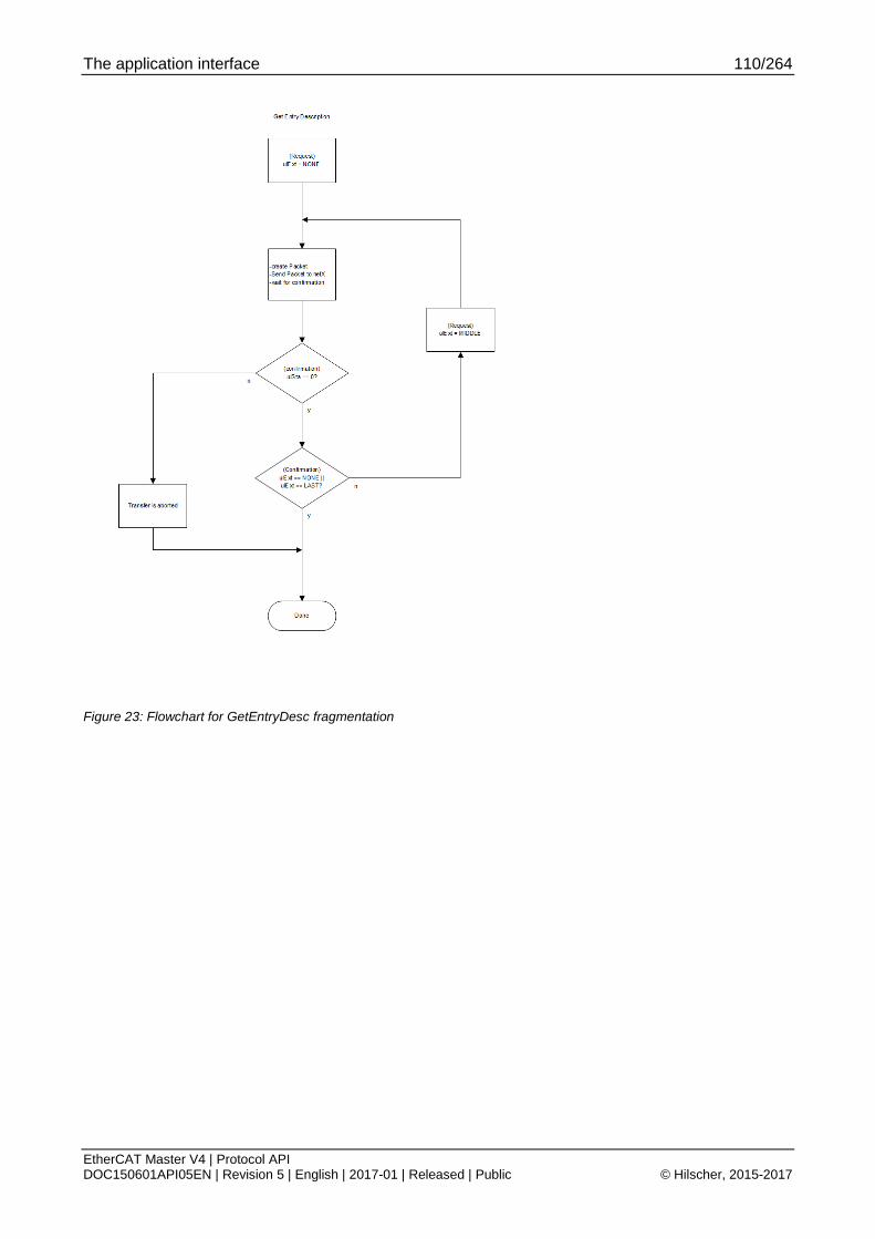
The application interface 110/264
EtherCAT Master V4 | Protocol API DOC150601API05EN | Revision 5 | English | 2017-01 | Released | Public © Hilscher, 2015-2017
Figure 23: Flowchart for GetEntryDesc fragmentation

The application interface 111/264
EtherCAT Master V4 | Protocol API DOC150601API05EN | Revision 5 | English | 2017-01 | Released | Public © Hilscher, 2015-2017
4.7.4 SDO access (Legacy)
4.7.4.1 Download/write SDO (Legacy)
This packet allows writing to an object/subobject.
Note: This packet is provided for applications migrating from ECM V3.X.
This packet does not support fragmentation.
The following addressing schemes are used:
During generic bus scan, use 4.1.3 Topology position
During normal operation, use 4.1.2 Fixed station address
Packet structure reference #define ETHERCAT_MASTER_COE_MAX_SDO_DOWNLOAD_DATA \ (RCX_MAX_DATA_SIZE – (sizeof(TLR_UINT32) * 4)) typedef struct ETHERCAT_MASTER_PACKET_SDO_DOWNLOAD_REQ_DATA_Ttag { uint32_t ulNodeId; uint32_t ulIndex; uint32_t ulSubIndex; uint32_t ulDataCnt; uint8_t abSdoData[ETHERCAT_MASTER_COE_MAX_SDO_DOWNLOAD_DATA]; } ETHERCAT_MASTER_PACKET_SDO_DOWNLOAD_REQ_DATA_T; typedef struct ETHERCAT_MASTER_PACKET_SDO_DOWNLOAD_REQ_Ttag { TLR_PACKET_HEADER_T tHead; ETHERCAT_MASTER_PACKET_SDO_DOWNLOAD_REQ_DATA_T tData; } ETHERCAT_MASTER_PACKET_SDO_DOWNLOAD_REQ_T;

The application interface 112/264
EtherCAT Master V4 | Protocol API DOC150601API05EN | Revision 5 | English | 2017-01 | Released | Public © Hilscher, 2015-2017
Packet description
Structure ETHERCAT_MASTER_PACKET_SDO_DOWNLOAD_REQ_T Type: Request
Variable Type Value / range Description tHead - Structure TLR_PACKET_HEADER_T ulDest UINT32 Destination queue-handle ulSrc UINT32 Source queue-handle ulDestId UINT32 Destination End Point Identifier, specifying the final receiver of the
packet within the Destination Process. Set to 0 for the Initialization Packet
ulSrcId UINT32 Source End Point Identifier, specifying the origin of the packet inside the Source Process
ulLen UINT32 16 + n Packet Data Length in bytes ulId UINT32 0 ... 232-1 Packet Identification as unique number generated by the Source
Process of the Packet ulSta UINT32 See section Status/Error codes overview ulCmd UINT32 0x650008 ETHERCAT_MASTER_CMD_SDO_DOWNLOAD_REQ - Command
ulExt UINT32 0 Extension not in use, set to zero for compatibility reasons ulRout UINT32 X Routing, do not touch
tData – Structure ETHERCAT_MASTER_PACKET_SDO_DOWNLOAD_REQ_DATA_T ulNodeId UINT32 During bus scan, use 4.1.3 Topology position
During normal operation, use 4.1.2 Fixed station address ulIndex UINT32 0 … 0xFFFF Index ulSubIndex UINT32 0 … 255 Subindex ulDataCnt UINT32 Data count abSdoData[n] UINT8[] SDO Data to be written
Actual data length is defined as ulLen - 16
Table 83: ETHERCAT_MASTER_CMD_SDO_DOWNLOAD_REQ – Download/write SDO request (Legacy)

The application interface 113/264
EtherCAT Master V4 | Protocol API DOC150601API05EN | Revision 5 | English | 2017-01 | Released | Public © Hilscher, 2015-2017
Packet structure reference typedef struct ETHERCAT_MASTER_PACKET_COE_SDO_DOWNLOAD_CNF_Ttag { TLR_PACKET_HEADER_T tHead; } ETHERCAT_MASTER_PACKET_SDO_DOWNLOAD_CNF_T;
Packet description
Structure ETHERCAT_MASTER_PACKET_SDO_DOWNLOAD_CNF_T Type: Confirmation
Variable Type Value / range Description tHead - Structure TLR_PACKET_HEADER_T
ulDest UINT32 Destination queue handle, unchanged ulSrc UINT32 Source queue handle, unchanged ulDestId UINT32 Destination End Point Identifier, specifying the final receiver of the packet
within the Destination Process. Set to 0 for the Initialization Packet ulSrcId UINT32 Source End Point Identifier, specifying the origin of the packet inside the
Source Process ulLen UINT32 0 Packet Data Length in bytes ulId UINT32 0 ... 232-1 Packet Identification, unchanged ulSta UINT32 See section Status/Error codes overview ulCmd UINT32 0x650009 ETHERCAT_MASTER_CMD_SDO_DOWNLOAD_CNF – Command
ulExt UINT32 0 Extension, reserved ulRout UINT32 x Routing information, do not change
Table 84: ETHERCAT_MASTER_CMD_SDO_DOWNLOAD_CNF – Download/write SDO confirmation (Legacy)

The application interface 114/264
EtherCAT Master V4 | Protocol API DOC150601API05EN | Revision 5 | English | 2017-01 | Released | Public © Hilscher, 2015-2017
4.7.4.2 Upload/read SDO (Legacy)
This packet allows reading to an object/subobject.
Note: This packet is provided for applications migrating from ECM V3.X.
This packet does not support fragmentation.
The following addressing schemes are used:
During generic bus scan, use 4.1.3 Topology position
During normal operation, use 4.1.2 Fixed station address
Packet structure reference typedef struct ETHERCAT_MASTER_PACKET_SDO_UPLOAD_REQ_DATA_Ttag { uint32_t ulNodeId; uint32_t ulIndex; uint32_t ulSubIndex; } ETHERCAT_MASTER_PACKET_SDO_UPLOAD_REQ_DATA_T; typedef struct ETHERCAT_MASTER_PACKET_SDO_UPLOAD_REQ_Ttag { TLR_PACKET_HEADER_T tHead; ETHERCAT_MASTER_PACKET_SDO_UPLOAD_REQ_DATA_T tData; } ETHERCAT_MASTER_PACKET_SDO_UPLOAD_REQ_T;
Packet description
Structure ETHERCAT_MASTER_PACKET_SDO_UPLOAD_REQ_T Type: Request
Variable Type Value / range Description tHead - Structure TLR_PACKET_HEADER_T
ulDest UINT32 Destination queue-handle ulSrc UINT32 Source queue-handle ulDestId UINT32 Destination End Point Identifier, specifying the final receiver of the
packet within the Destination Process. Set to 0 for the Initialization Packet
ulSrcId UINT32 Source End Point Identifier, specifying the origin of the packet inside the Source Process
ulLen UINT32 12 Packet Data Length in bytes ulId UINT32 0 ... 232-1 Packet Identification as unique number generated by the Source
Process of the Packet ulSta UINT32 See section Status/Error codes overview ulCmd UINT32 0x650006 ETHERCAT_MASTER_CMD_SDO_UPLOAD_REQ - Command
ulExt UINT32 0 Extension not in use, set to zero for compatibility reasons ulRout UINT32 X Routing, do not touch
tData – Structure ETHERCAT_MASTER_PACKET_SDO_UPLOAD_REQ_DATA_T ulNodeId UINT32 During bus scan, use 4.1.3 Topology position
During normal operation, use 4.1.2 Fixed station address ulIndex UINT32 0…0xFFFF Index ulSubIndex UINT32 0…255 Subindex
Table 85: ETHERCAT_MASTER_CMD_SDO_UPLOAD_REQ – Upload/read SDO request (Legacy)

The application interface 115/264
EtherCAT Master V4 | Protocol API DOC150601API05EN | Revision 5 | English | 2017-01 | Released | Public © Hilscher, 2015-2017
Packet structure reference #define ETHERCAT_MASTER_COE_MAX_SDO_UPLOAD_DATA \ (RCX_MAX_DATA_SIZE – (sizeof(TLR_UINT32) * 4)) typedef struct ETHERCAT_MASTER_PACKET_SDO_UPLOAD_CNF_DATA_Ttag { uint32_t ulNodeId; uint32_t ulIndex; uint32_t ulSubIndex; uint32_t ulDataCnt; uint8_t abSdoData[ETHERCAT_MASTER_COE_MAX_SDO_UPLOAD_DATA]; } ETHERCAT_MASTER_SDO_UPLOAD_CNF_DATA_T; typedef struct ETHERCAT_MASTER_PACKET_SDO_UPLOAD_CNF_Ttag { TLR_PACKET_HEADER_T tHead; ETHERCAT_MASTER_PACKET_SDO_UPLOAD_CNF_DATA_T tData; } ETHERCAT_MASTER_PACKET_SDO_UPLOAD_CNF_T;
Packet description
Structure ETHERCAT_MASTER_SDO_UPLOAD_CNF_T Type: Confirmation
Variable Type Value / range Description tHead - Structure TLR_PACKET_HEADER_T ulDest UINT32 Destination queue handle, unchanged ulSrc UINT32 Source queue handle, unchanged ulDestId UINT32 Destination End Point Identifier, specifying the final receiver of the packet
within the Destination Process. Set to 0 for the Initialization Packet
ulSrcId UINT32 Source End Point Identifier, specifying the origin of the packet inside the Source Process
ulLen UINT32 16 + n Packet Data Length in bytes ulId UINT32 0 ... 232-1 Packet Identification, unchanged ulSta UINT32 See section Status/Error codes overview ulCmd UINT32 0x650007 ETHERCAT_MASTER_CMD_SDO_UPLOAD_CNF – Command
ulExt UINT32 0 Extension, reserved ulRout UINT32 x Routing information, do not change
tData – Structure ECM_IF_COE_SDO_UPLOAD_CNF_DATA_T ulNodeId UINT32 Value from request ulIndex UINT32 Value from request ulSubIndex UINT32 Value from request ulDataCnt UINT32 Length of data read
Same value as n abSdoData[n] UINT8[] Data being read
Actual length is ulDataCnt
Table 86: ETHERCAT_MASTER_CMD_SDO_UPLOAD_CNF – Upload/read SDO confirmation (Legacy)

The application interface 116/264
EtherCAT Master V4 | Protocol API DOC150601API05EN | Revision 5 | English | 2017-01 | Released | Public © Hilscher, 2015-2017
4.7.5 SDOINFO access (Legacy)
4.7.5.1 Get object list (OdList) (Legacy)
Note: This packet is provided for applications migrating from ECM V3.X.
This packet does not support fragmentation.
The following addressing schemes are used:
During generic bus scan, use 4.1.3 Topology position
During normal operation, use 4.1.2 Fixed station address
Packet structure reference typedef struct ETHERCAT_MASTER_PACKET_GET_ODLIST_REQ_DATA_Ttag { uint32_t ulNodeId; uint32_t ulListType; } ETHERCAT_MASTER_PACKET_GET_ODLIST_REQ_DATA_T; typedef struct ETHERCAT_MASTER_PACKET_GET_ODLIST_REQ_Ttag { TLR_PACKET_HEADER_T tHead; ETHERCAT_MASTER_PACKET_GET_ODLIST_REQ_DATA_T tData; } ETHERCAT_MASTER_PACKET_GET_ODLIST_REQ_T;
Packet description
Structure ETHERCAT_MASTER_PACKET_GET_ODLIST_REQ_T Type: Request
Variable Type Value / range Description tHead - Structure TLR_PACKET_HEADER_T ulDest UINT32 Destination queue-handle ulSrc UINT32 Source queue-handle ulDestId UINT32 Destination End Point Identifier, specifying the final receiver of the
packet within the Destination Process. Set to 0 for the Initialization Packet
ulSrcId UINT32 Source End Point Identifier, specifying the origin of the packet inside the Source Process
ulLen UINT32 8 Packet Data Length in bytes ulId UINT32 0 ... 232-1 Packet Identification as unique number generated by the Source
Process of the Packet
ulSta UINT32 See section Status/Error codes overview ulCmd UINT32 0x65000A ETHERCAT_MASTER_CMD_GET_ODLIST_REQ - Command
ulExt UINT32 0 Extension not in use, set to zero for compatibility reasons ulRout UINT32 X Routing, do not touch
tData – Structure ETHERCAT_MASTER_PACKET_GET_ODLIST_REQ_DATA_T ulNodeId UINT32 During bus scan, use 4.1.3 Topology position
During normal operation, use 4.1.2 Fixed station address ulListType UINT32 1 … 5 List type, see Table 88: Possible values of ulListType below
Table 87: ETHERCAT_MASTER_CMD_GET_ODLIST_REQ – Get object list request (Legacy)

The application interface 117/264
EtherCAT Master V4 | Protocol API DOC150601API05EN | Revision 5 | English | 2017-01 | Released | Public © Hilscher, 2015-2017
Definition of ulListType
Value Definition / description 0x0001 ETHERCAT_MASTER_COE_GET_ODLIST_TYPE_ALL
Retrieve list of all existing objects 0x0002 ETHERCAT_MASTER_COE_GET_ODLIST_TYPE_RXPDOMAP
Retrieve list of all RxPDO objects which can be mapped 0x0003 ETHERCAT_MASTER_COE_GET_ODLIST_TYPE_TXPDOMAP
Retrieve list of all TxPDO objects which can be mapped 0x0004 ETHERCAT_MASTER_COE_GET_ODLIST_TYPE_STORE
Retrieve list of all objects necessary for backup 0x0005 ETHERCAT_MASTER_COE_GET_ODLIST_TYPE_STARTUP
Retrieve list of all objects used during startup
Table 88: Possible values of ulListType

The application interface 118/264
EtherCAT Master V4 | Protocol API DOC150601API05EN | Revision 5 | English | 2017-01 | Released | Public © Hilscher, 2015-2017
Packet structure reference #define ETHERCAT_MASTER_COE_GET_ODLIST_DATA \ ((RCX_MAX_DATA_SIZE – (sizeof(TLR_UINT32) * 3)) / sizeof(TLR_UINT16)) typedef struct ETHERCAT_MASTER_PACKET_GET_ODLIST_CNF_DATA_Ttag { uint32_t ulNodeId; uint32_t ulListType; uint32_t ulDataCnt; uint16_t ausObjectList[ETHERCAT_MASTER_COE_GET_ODLIST_DATA]; } ETHERCAT_MASTER_PACKET_GET_ODLIST_CNF_DATA_T; typedef struct ETHERCAT_MASTER_PACKET_GET_ODLIST_CNF_Ttag { TLR_PACKET_HEADER_T tHead; ETHERCAT_MASTER_PACKET_GET_ODLIST_CNF_DATA_T tData; } ETHERCAT_MASTER_PACKET_GET_ODLIST_CNF_T;
Packet description
Structure ETHERCAT_MASTER_PACKET_GET_ODLIST_CNF_T Type: Confirmation
Variable Type Value / range Description tHead - Structure TLR_PACKET_HEADER_T ulDest UINT32 Destination queue handle, unchanged ulSrc UINT32 Source queue handle, unchanged ulDestId UINT32 Destination End Point Identifier, specifying the final receiver of the packet
within the Destination Process. Set to 0 for the Initialization Packet
ulSrcId UINT32 Source End Point Identifier, specifying the origin of the packet inside the Source Process
ulLen UINT32 12 + n * 2 8 on error
Packet Data Length in bytes
ulId UINT32 0 ... 232-1 Packet Identification, unchanged ulSta UINT32 See section Status/Error codes overview ulCmd UINT32 0x65000B ETHERCAT_MASTER_CMD_GET_ODLIST_CNF – Command
ulExt UINT32 0 Extension, reserved ulRout UINT32 x Routing information, do not change
tData – Structure ETHERCAT_MASTER_PACKET_GET_ODLIST_CNF_DATA_T ulNodeId UINT32 Value from request ulListType UINT32 Value from request ulDataCnt UINT32 Data count ausObjectList[n]
UINT16[]
List of object indices
Table 89: ETHERCAT_MASTER_CMD_GET_ODLIST_CNF – Get object list confirmation (Legacy)

The application interface 119/264
EtherCAT Master V4 | Protocol API DOC150601API05EN | Revision 5 | English | 2017-01 | Released | Public © Hilscher, 2015-2017
4.7.5.2 Get object description (ObjDesc) (Legacy)
Note: This packet is provided for applications migrating from ECM V3.X. This packet does not support fragmentation.
The following addressing schemes are used:
During generic bus scan, use 4.1.3 Topology position
During normal operation, use 4.1.2 Fixed station address
Packet structure reference typedef struct ETHERCAT_MASTER_PACKET_GET_OBJECTDESC_REQ_DATA_Ttag { uint32_t ulNodeId; uint32_t ulIndex; } ETHERCAT_MASTER_PACKET_GET_OBJECTDESC_REQ_DATA_T; typedef struct ETHERCAT_MASTER_PACKET_GET_OBJECTDESC_REQ_Ttag { TLR_PACKET_HEADER_T tHead; ETHERCAT_MASTER_PACKET_GET_OBJDESC_REQ_DATA_T tData; } ETHERCAT_MASTER_PACKET_GET_OBJECTDESC_REQ_T;
Packet description
Structure ETHERCAT_MASTER_GET_OBJECTDESC_REQ_T Type: Request
Variable Type Value / range Description tHead - Structure TLR_PACKET_HEADER_T ulDest UINT32 Destination queue-handle ulSrc UINT32 Source queue-handle ulDestId UINT32 Destination End Point Identifier, specifying the final receiver of the
packet within the Destination Process. Set to 0 for the Initialization Packet
ulSrcId UINT32 Source End Point Identifier, specifying the origin of the packet inside the Source Process
ulLen UINT32 16 Packet Data Length in bytes ulId UINT32 0 ... 232-1 Packet Identification as unique number generated by the Source
Process of the Packet ulSta UINT32 See section Status/Error codes overview ulCmd UINT32 0x650018 ETHERCAT_MASTER_CMD_GET_OBJECTDESC_REQ - Command
ulExt UINT32 0 Extension not in use, set to zero for compatibility reasons ulRout UINT32 X Routing, do not touch
tData – Structure ECM_IF_COE_SDOINFO_GETOBJDESC_REQ_DATA_T ulNodeId UINT32 During bus scan, use 4.1.3 Topology position
During normal operation, use 4.1.2 Fixed station address ulIndex UINT32 0 … 0xFFFF Index of object
Table 90: ETHERCAT_MASTER_CMD_GET_OBJECTDESC_REQ – Get object description request (Legacy)
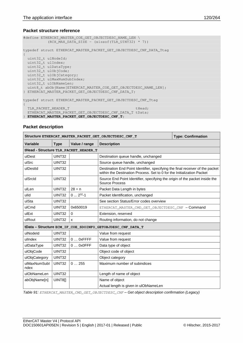
The application interface 120/264
EtherCAT Master V4 | Protocol API DOC150601API05EN | Revision 5 | English | 2017-01 | Released | Public © Hilscher, 2015-2017
Packet structure reference #define ETHERCAT_MASTER_COE_GET_OBJECTDESC_NAME_LEN \ (RCX_MAX_DATA_SIZE – (sizeof(TLR_UINT32) * 7)) typedef struct ETHERCAT_MASTER_PACKET_GET_OBJECTDESC_CNF_DATA_Ttag { uint32_t ulNodeId; uint32_t ulIndex; uint32_t ulDataType; uint32_t ulObjCode; uint32_t ulObjCategory; uint32_t ulMaxNumSubIndex; uint32_t ulObNameLen; uint8_t abObjName[ETHERCAT_MASTER_COE_GET_OBJECTDESC_NAME_LEN]; } ETHERCAT_MASTER_PACKET_GET_OBJECTDESC_CNF_DATA_T; typedef struct ETHERCAT_MASTER_PACKET_GET_OBJECTDESC_CNF_Ttag { TLR_PACKET_HEADER_T tHead; ETHERCAT_MASTER_PACKET_GET_OBJECTDESC_CNF_DATA_T tData; } ETHERCAT_MASTER_PACKET_GET_OBJECTDESC_CNF_T;
Packet description
Structure ETHERCAT_MASTER_PACKET_GET_OBJECTDESC_CNF_T Type: Confirmation
Variable Type Value / range Description tHead - Structure TLR_PACKET_HEADER_T ulDest UINT32 Destination queue handle, unchanged ulSrc UINT32 Source queue handle, unchanged ulDestId UINT32 Destination End Point Identifier, specifying the final receiver of the packet
within the Destination Process. Set to 0 for the Initialization Packet ulSrcId UINT32 Source End Point Identifier, specifying the origin of the packet inside the
Source Process ulLen UINT32 28 + n Packet Data Length in bytes ulId UINT32 0 ... 232-1 Packet Identification, unchanged ulSta UINT32 See section Status/Error codes overview ulCmd UINT32 0x650019 ETHERCAT_MASTER_CMD_GET_OBJECTDESC_CNF – Command
ulExt UINT32 0 Extension, reserved ulRout UINT32 x Routing information, do not change
tData – Structure ECM_IF_COE_SDOINFO_GETOBJDESC_CNF_DATA_T
ulNodeId UINT32 Value from request ulIndex UINT32 0 … 0xFFFF Value from request ulDataType UINT32 0 … 0x0FFF Data type of object ulObjCode UINT32 Object code of object ulObjCategory UINT32 Object category ulMaxNumSubIndex
UINT32 0 … 255 Maximum number of subindices
ulObNameLen UINT32 Length of name of object abObjName[n] UINT8[] Name of object
Actual length is given in ulObNameLen
Table 91: ETHERCAT_MASTER_CMD_GET_OBJECTDESC_CNF – Get object description confirmation (Legacy)
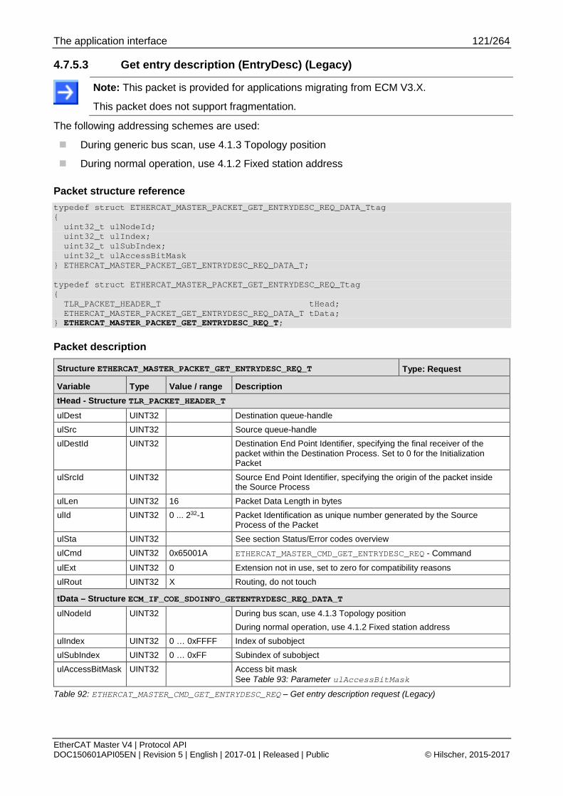
The application interface 121/264
EtherCAT Master V4 | Protocol API DOC150601API05EN | Revision 5 | English | 2017-01 | Released | Public © Hilscher, 2015-2017
4.7.5.3 Get entry description (EntryDesc) (Legacy)
Note: This packet is provided for applications migrating from ECM V3.X.
This packet does not support fragmentation.
The following addressing schemes are used:
During generic bus scan, use 4.1.3 Topology position
During normal operation, use 4.1.2 Fixed station address
Packet structure reference typedef struct ETHERCAT_MASTER_PACKET_GET_ENTRYDESC_REQ_DATA_Ttag { uint32_t ulNodeId; uint32_t ulIndex; uint32_t ulSubIndex; uint32_t ulAccessBitMask } ETHERCAT_MASTER_PACKET_GET_ENTRYDESC_REQ_DATA_T; typedef struct ETHERCAT_MASTER_PACKET_GET_ENTRYDESC_REQ_Ttag { TLR_PACKET_HEADER_T tHead; ETHERCAT_MASTER_PACKET_GET_ENTRYDESC_REQ_DATA_T tData; } ETHERCAT_MASTER_PACKET_GET_ENTRYDESC_REQ_T;
Packet description
Structure ETHERCAT_MASTER_PACKET_GET_ENTRYDESC_REQ_T Type: Request
Variable Type Value / range Description tHead - Structure TLR_PACKET_HEADER_T
ulDest UINT32 Destination queue-handle ulSrc UINT32 Source queue-handle ulDestId UINT32 Destination End Point Identifier, specifying the final receiver of the
packet within the Destination Process. Set to 0 for the Initialization Packet
ulSrcId UINT32 Source End Point Identifier, specifying the origin of the packet inside the Source Process
ulLen UINT32 16 Packet Data Length in bytes ulId UINT32 0 ... 232-1 Packet Identification as unique number generated by the Source
Process of the Packet ulSta UINT32 See section Status/Error codes overview ulCmd UINT32 0x65001A ETHERCAT_MASTER_CMD_GET_ENTRYDESC_REQ - Command
ulExt UINT32 0 Extension not in use, set to zero for compatibility reasons ulRout UINT32 X Routing, do not touch
tData – Structure ECM_IF_COE_SDOINFO_GETENTRYDESC_REQ_DATA_T ulNodeId UINT32 During bus scan, use 4.1.3 Topology position
During normal operation, use 4.1.2 Fixed station address ulIndex UINT32 0 … 0xFFFF Index of subobject ulSubIndex UINT32 0 … 0xFF Subindex of subobject ulAccessBitMask UINT32 Access bit mask
See Table 93: Parameter ulAccessBitMask
Table 92: ETHERCAT_MASTER_CMD_GET_ENTRYDESC_REQ – Get entry description request (Legacy)

The application interface 122/264
EtherCAT Master V4 | Protocol API DOC150601API05EN | Revision 5 | English | 2017-01 | Released | Public © Hilscher, 2015-2017
Meaning of ulAccessBitMask Bits Name (Bit mask) Description
31 ... 7 Reserved Reserved for future use
6 ETHERCAT_MASTER_COE_ENTRY_MAXVALUE (0x00000040)
Maximum value
5 ETHERCAT_MASTER_COE_ENTRY_MINVALUE (0x00000020)
Minimum value
4 ETHERCAT_MASTER_COE_ENTRY_DEFAULTVALUE (0x00000010)
Default value
3 ETHERCAT_MASTER_COE_ENTRY_UNITTYPE (0x00000008)
Unit
2 ETHERCAT_MASTER_COE_ENTRY_PDOMAPPING (0x00000004)
Information whether the object can be mapped to PDO
It is always requested. Bit definition is provided for legacy use.
1 ETHERCAT_MASTER_COE_ENTRY_OBJCATEGORY (0x00000002)
Object category
It is always requested. Bit definition is provided for legacy use.
0 ETHERCAT_MASTER_COE_ENTRY_OBJACCESS (0x00000001)
Object access rights
It is always requested. Bit definition is provided for legacy use.
Table 93: Parameter ulAccessBitMask

The application interface 123/264
EtherCAT Master V4 | Protocol API DOC150601API05EN | Revision 5 | English | 2017-01 | Released | Public © Hilscher, 2015-2017
Packet structure reference #define ETHERCAT_MASTER_COE_GET_ENTRYDESC_MAX_DATA \ (RCX_MAX_DATA_SIZE – (sizeof(TLR_UINT32) * 11)) typedef struct ETHERCAT_MASTER_PACKET_GET_ENTRYDESC_CNF_DATA_Ttag { uint32_t ulNodeId; uint32_t ulIndex; uint32_t ulSubIndex; uint32_t ulValueInfo; uint32_t ulDataType; uint32_t ulBitLen; uint32_t ulObAccess; uint32_t fRxPdoMapping; uint32_t fTxPdoMapping; uint32_t ulUnitType; uint32_t ulDataLen; uint8_t abObjData[1024]; } ETHERCAT_MASTER_GET_ENTRYDESC_CNF_DATA_T; typedef struct ETHERCAT_MASTER_PACKET_GET_ENTRYDESC_CNF_Ttag { TLR_PACKET_HEADER_T tHead; ETHERCAT_MASTER_PACKET_GET_ENTRYDESC_CNF_DATA_T tData; } ETHERCAT_MASTER_PACKET_GET_ENTRYDESC_CNF_T;

The application interface 124/264
EtherCAT Master V4 | Protocol API DOC150601API05EN | Revision 5 | English | 2017-01 | Released | Public © Hilscher, 2015-2017
Packet description
Structure ETHERCAT_MASTER_PACKET_GET_ENTRYDESC_CNF_T Type: Confirmation
Variable Type Value / range Description tHead - Structure TLR_PACKET_HEADER_T ulDest UINT32 Destination queue handle, unchanged ulSrc UINT32 Source queue handle, unchanged ulDestId UINT32 Destination End Point Identifier, specifying the final receiver of the packet
within the Destination Process. Set to 0 for the Initialization Packet
ulSrcId UINT32 Source End Point Identifier, specifying the origin of the packet inside the Source Process
ulLen UINT32 44 + n Packet Data Length in bytes ulId UINT32 0 ... 232-1 Packet Identification, unchanged ulSta UINT32 See section Status/Error codes overview ulCmd UINT32 0x65001B ETHERCAT_MASTER_CMD_GET_ENTRYDESC_CNF – Command
ulExt UINT32 0 Extension, reserved ulRout UINT32 x Routing information, do not change
tData – Structure ETHERCAT_MASTER_PACKET_GET_ENTRYDESC_CNF_DATA_T ulNodeId UINT32 Value from request ulIndex UINT32 Value from request ulSubIndex UINT32 Value from request ulValueInfo UINT32 Bits 0 to 2 are always set for legacy applications ulDataType UINT32 0 … 0x0FFF Data type of sub index ulBitLen UINT32 0 … 0xFFFF Bit length of subindex
If value is 0xFFFF, the actual bit length has to be determined by read ulObAccess UINT32 Access bit mask
See Table 93: Parameter ulAccessBitMask
fRxPdoMapping
BOOL RxPDO Mapping
fTxPdoMapping BOOL TxPDO Mapping ulUnitType UINT32 Unit Type according ETG.1004 ulDataLen UINT32 Length of data in abObjData
abObjData[n] UINT8[] Remaining object data Actual length is given by ulDataLen
Table 94: ETHERCAT_MASTER_CMD_GET_ENTRYDESC_CNF – Get entry description confirmation (Legacy)

The application interface 125/264
EtherCAT Master V4 | Protocol API DOC150601API05EN | Revision 5 | English | 2017-01 | Released | Public © Hilscher, 2015-2017
Bit mask for ulAccessBitMask and ulValueInfo
Bit No. Definition / description
6 ETHERCAT_MASTER_COE_ENTRY_MAXVALUE
In request, this bit defines whether Maximum Value is to be requested by master.
In confirmation, this bit defines whether Maximum Value is available and has been requested.
5 ETHERCAT_MASTER_COE_ENTRY_MINVALUE
In request, this bit defines whether Minimum Value is to be requested by master.
In confirmation, this bit defines whether Minimum Value is available and has been requested.
4 ETHERCAT_MASTER_COE_ENTRY_DEFAULTVALUE
In request, this bit defines whether Default Value is to be requested by master.
In confirmation, this bit defines whether Default Value is available and has been requested.
3 ETHERCAT_MASTER_COE_ENTRY_UNITTYPE
In request, this bit defines whether Unit type is to be requested by master.
In confirmation, this bit defines whether unit type is available and has been requested.
2 ETHERCAT_MASTER_COE_ENTRY_PDOMAPPING
PDO Mapping flags are always requested and therefore this bit is always set to 1 in response.
1 ETHERCAT_MASTER_COE_ENTRY_OBJCATEGORY
Object category is always requested and therefore this bit is always set to 1 in response.
0 ETHERCAT_MASTER_COE_ENTRY_OBJACCESS
Object access is always requested and therefore this bit is always set to 1 in response.
Table 95: Meaning of ulAccessBitMask and ulValueInfo

The application interface 126/264
EtherCAT Master V4 | Protocol API DOC150601API05EN | Revision 5 | English | 2017-01 | Released | Public © Hilscher, 2015-2017
4.8 FoE services FoE services are implemented starting with V4.3.
4.8.1 Slave state accessibility FoE access is possible in the following slave states if supported by slave:
BOOT (if supported by slave)
PREOP
SAFEOP
OP
Slaves may limit access depending on slave state to certain files.
4.8.2 Fragmentation of write file (FoE) Flow charts are presented in chapter 4.8.5 FoE fragmentation flowcharts.
When the data fits into a single fragment, the following sequence is used:
Figure 24: Single fragment handling of write file service

The application interface 127/264
EtherCAT Master V4 | Protocol API DOC150601API05EN | Revision 5 | English | 2017-01 | Released | Public © Hilscher, 2015-2017
When two or more fragments are required for the transfer, the following sequence diagrams apply:
Figure 25: Two Fragment handling of write file service
Figure 26: Multiple fragment handling of write file service

The application interface 128/264
EtherCAT Master V4 | Protocol API DOC150601API05EN | Revision 5 | English | 2017-01 | Released | Public © Hilscher, 2015-2017
4.8.3 Fragmentation of read IDN (SoE) Flow charts are presented in chapter 4.8.5 FoE fragmentation flowcharts.
When the data fit into a single fragment, the following sequence is used:
Figure 27: Single fragment handling of read file service
When two or more fragments are required for the transfer, the following sequence diagrams apply:
Figure 28: Two fragment handling of read file service

The application interface 129/264
EtherCAT Master V4 | Protocol API DOC150601API05EN | Revision 5 | English | 2017-01 | Released | Public © Hilscher, 2015-2017
Figure 29: Multiple fragment handling of read file service

The application interface 130/264
EtherCAT Master V4 | Protocol API DOC150601API05EN | Revision 5 | English | 2017-01 | Released | Public © Hilscher, 2015-2017
4.8.4 Packets
4.8.4.1 Write file (FoE)
The following addressing schemes are used:
During generic bus scan, use 4.1.3 Topology position
During normal operation, use 4.1.2 Fixed station address
ulDestId has to be handled as follows:
First fragment has ulDestId == 0
Stack returns first fragment confirmation with ulDestId != 0
This ulDestId has to be provided to all subsequent fragments
Packet structure reference typedef struct ECM_IF_FOE_WRITE_REQ_DATA_FIRST_Ttag { uint16_t usStationAddress; uint16_t usTransportType; uint16_t usAoEPort; uint32_t ulTotalBytes; uint32_t ulTimeoutMs; uint32_t ulPassword; uint32_t ulFileNameBytes; uint8_t abData[1024]; } ECM_IF_FOE_WRITE_REQ_DATA_FIRST_T; typedef struct ECM_IF_FOE_WRITE_REQ_DATA_SEG_Ttag { uint16_t usStationAddress; uint16_t usTransportType; uint16_t usAoEPort; uint32_t ulTotalBytes; uint32_t ulTimeoutMs; uint8_t abData[1024]; } ECM_IF_FOE_WRITE_REQ_DATA_SEG_T; typedef union ECM_IF_FOE_WRITE_REQ_DATA_Ttag { ECM_IF_FOE_WRITE_REQ_DATA_FIRST_T tFirst; ECM_IF_FOE_WRITE_REQ_DATA_SEG_T tSeg; } ECM_IF_FOE_WRITE_REQ_DATA_T; typedef struct ECM_IF_FOE_WRITE_REQ_Ttag { TLR_PACKET_HEADER_T tHead; ECM_IF_FOE_WRITE_REQ_DATA_T tData; } ECM_IF_FOE_WRITE_REQ_T;

The application interface 131/264
EtherCAT Master V4 | Protocol API DOC150601API05EN | Revision 5 | English | 2017-01 | Released | Public © Hilscher, 2015-2017
Packet description (First segment)
Structure ECM_IF_SOE_WRITE_REQ_T Type: Request
Variable Type Value / range Description tHead - Structure TLR_PACKET_HEADER_T ulDest UINT32 Destination queue-handle ulSrc UINT32 Source queue-handle ulDestId UINT32 Destination End Point Identifier, specifying the final receiver of the
packet within the Destination Process. Set to 0 for the Initialization Packet
ulSrcId UINT32 Source End Point Identifier, specifying the origin of the packet inside the Source Process
ulLen UINT32 22 + n Packet Data Length in bytes ulId UINT32 0 ... 232-1 Packet Identification as unique number generated by the Source
Process of the Packet ulSta UINT32 See section Status/Error codes overview ulCmd UINT32 0x9900 ECM_IF_CMD_FOE_WRITE_REQ - Command
ulExt UINT32 0 Extension not in use, set to zero for compatibility reasons ulRout UINT32 X Routing, do not touch
tData – Structure ECM_IF_FOE_WRITE_REQ_DATA_T usStationAddress UINT16 Valid address During bus scan, use 4.1.3 Topology position
During normal operation, use 4.1.2 Fixed station address usTransportType UINT16 0,1 Transport type
0: FoE transport (ECM_IF_FOE_TRANSPORT_FOE), 1: AoE transport (ECM_IF_FOE_TRANSPORT_AOE)
usAoEPort UINT16 0 … 65535 AoEPort (only used if usTransportType = 1)
ulTotalBytes UINT32 0 ... 232-1 Summed length of all abData of all fragments
ulTimeoutMs UINT32 Timeout in ms ulPassword UINT32 0 ... 232-1 FoE password to be used ulFileNameBytes UINT32 Number of bytes used for file name including its NUL terminator abData[n] UINT8[] Data of a fragment. Actual byte length is given as ulLen – 22
The first segment contains the NUL-terminated file name. Its length is given by ulFileNameBytes.
Table 96: ECM_IF_CMD_FOE_WRITE_REQ – Write file request (FoE, First segment)

The application interface 132/264
EtherCAT Master V4 | Protocol API DOC150601API05EN | Revision 5 | English | 2017-01 | Released | Public © Hilscher, 2015-2017
Packet description (Following segments)
Structure ECM_IF_SOE_WRITE_REQ_T Type: Request
Variable Type Value / range Description tHead - Structure TLR_PACKET_HEADER_T ulDest UINT32 Destination queue-handle ulSrc UINT32 Source queue-handle ulDestId UINT32 Destination End Point Identifier, specifying the final receiver of the
packet within the Destination Process. Set to 0 for the Initialization Packet
ulSrcId UINT32 Source End Point Identifier, specifying the origin of the packet inside the Source Process
ulLen UINT32 18 + n Packet Data Length in bytes ulId UINT32 0 ... 232-1 Packet Identification as unique number generated by the Source
Process of the Packet ulSta UINT32 See section Status/Error codes overview ulCmd UINT32 0x9900 ECM_IF_CMD_FOE_WRITE_REQ - Command
ulExt UINT32 0 Extension not in use, set to zero for compatibility reasons ulRout UINT32 X Routing, do not touch
tData – Structure ECM_IF_FOE_WRITE_REQ_DATA_T usStationAddress UINT16 Valid address During bus scan, use 4.1.3 Topology position
During normal operation, use 4.1.2 Fixed station address usTransportType UINT16 0,1 Transport type
0: FoE transport (ECM_IF_FOE_TRANSPORT_FOE), 1: AoE transport (ECM_IF_FOE_TRANSPORT_AOE)
usAoEPort UINT16 0 … 65535 AoEPort (only used if usTransportType = 1)
ulTotalBytes UINT32 0 ... 232-1 Summed length of all abData of all fragments
ulTimeoutMs UINT32 Timeout in ms abData[n] UINT8[] Data of a fragment. Actual byte length is given as ulLen - 18
Table 97: ECM_IF_CMD_FOE_WRITE_REQ – Write file request (FoE, Following segment)
Timeout value ulTimeoutMs
It is recommended to use at least 1000 ms as value. However, slaves exist that need higher timeout value due to their way of functioning.

The application interface 133/264
EtherCAT Master V4 | Protocol API DOC150601API05EN | Revision 5 | English | 2017-01 | Released | Public © Hilscher, 2015-2017
Packet structure reference typedef struct ECM_IF_FOE_WRITE_CNF_DATA_Ttag { uint16_t usStationAddress; uint16_t usTransportType; uint16_t usAoEPort; uint32_t ulTotalBytes; uint32_t ulTimeoutMs; uint8_t abErrorText[ECM_IF_FOE_MAX_ERROR_TEXT_BYTE_LEN]; } ECM_IF_FOE_WRITE_CNF_DATA_T; typedef struct ECM_IF_FOE_WRITE_CNF_Ttag { TLR_PACKET_HEADER_T tHead; ECM_IF_FOE_WRITE_CNF_DATA_T tData; } ECM_IF_FOE_WRITE_CNF_T;
Packet description
Structure ECM_IF_FOE_WRITE_CNF_T Type: Confirmation
Variable Type Value / range Description tHead - Structure TLR_PACKET_HEADER_T ulDest UINT32 Destination queue handle, unchanged ulSrc UINT32 Source queue handle, unchanged ulDestId UINT32 Destination End Point Identifier, specifying the final receiver of the packet
within the Destination Process. Set to 0 for the Initialization Packet ulSrcId UINT32 Source End Point Identifier, specifying the origin of the packet inside the
Source Process
ulLen UINT32 14 + n Packet Data Length in bytes ulId UINT32 0 ... 232-1 Packet Identification, unchanged ulSta UINT32 See section Status/Error codes overview ulCmd UINT32 0x9901 ECM_IF_CMD_FOE_WRITE_CNF – Command
ulExt UINT32 0 Extension, reserved ulRout UINT32 x Routing information, do not change
tData – Structure ECM_IF_FOE_WRITE_CNF_DATA_T usStationAddress
UINT16 Valid address Value from request
usTransportType
UINT16 0,1 Value from request
usAoEPort UINT16 Value from request ulTotalBytes UINT32 Value from request ulTimeoutMs UINT32 Value from request abErrorText UINT8[n
] Optionally a NUL-terminated string of n bytes produced by slave when
ulSta != 0
Table 98: ECM_IF_CMD_FOE_WRITE_CNF – Write file confirmation

The application interface 134/264
EtherCAT Master V4 | Protocol API DOC150601API05EN | Revision 5 | English | 2017-01 | Released | Public © Hilscher, 2015-2017
4.8.4.2 Read file (FoE)
The following addressing schemes are used:
During generic bus scan, use 4.1.3 Topology position
During normal operation, use 4.1.2 Fixed station address
ulDestId has to be handled as follows:
First fragment has ulDestId == 0
Stack returns first fragment confirmation with ulDestId != 0
This ulDestId has to be provided to all subsequent fragments
Packet structure reference typedef struct ECM_IF_FOE_READ_REQ_DATA_FIRST_Ttag { uint16_t usStationAddress; uint16_t usTransportType; uint16_t usAoEPort; uint32_t ulTimeoutMs; uint32_t ulMaxTotalBytes; uint32_t ulPassword; uint8_t abFileName[1024]; } ECM_IF_SOE_READ_REQ_DATA_FIRST_T; typedef struct ECM_IF_FOE_READ_REQ_DATA_SEG_Ttag { uint16_t usStationAddress; uint16_t usTransportType; uint16_t usAoEPort; uint32_t ulTimeoutMs; uint32_t ulMaxTotalBytes; } ECM_IF_FOE_READ_REQ_DATA_SEG_T; typedef union ECM_IF_FOE_READ_REQ_DATA_Ttag { ECM_IF_FOE_READ_REQ_DATA_FIRST_T tFirst; ECM_IF_FOE_READ_REQ_DATA_SEG_T tSeg; } ECM_IF_FOE_READ_REQ_DATA_T; typedef struct ECM_IF_FOE_READ_REQ_Ttag { TLR_PACKET_HEADER_T tHead; ECM_IF_FOE_READ_REQ_DATA_T tData; } ECM_IF_FOE_READ_REQ_T;

The application interface 135/264
EtherCAT Master V4 | Protocol API DOC150601API05EN | Revision 5 | English | 2017-01 | Released | Public © Hilscher, 2015-2017
Packet description (First segment)
Structure ECM_IF_FOE_READ_REQ_T Type: Request
Variable Type Value / range Description tHead - Structure TLR_PACKET_HEADER_T ulDest UINT32 Destination queue-handle ulSrc UINT32 Source queue-handle ulDestId UINT32 Destination End Point Identifier, specifying the final receiver of the
packet within the Destination Process. Set to 0 for the Initialization Packet
ulSrcId UINT32 Source End Point Identifier, specifying the origin of the packet inside the Source Process
ulLen UINT32 18 + n Packet Data Length in bytes ulId UINT32 0 ... 232-1 Packet Identification as unique number generated by the Source
Process of the Packet ulSta UINT32 See section Status/Error codes overview ulCmd UINT32 0x9902 ECM_IF_CMD_FOE_READ_REQ - Command
ulExt UINT32 0 Extension not in use, set to zero for compatibility reasons ulRout UINT32 X Routing, do not touch
tData – Structure ECM_IF_FOE_READ_REQ_DATA_T usStationAddress
UINT16 Valid address During bus scan, use 4.1.3 Topology position During normal operation, use 4.1.2 Fixed station address
usTransportType UINT16 0,1 Transport type 0: FoE transport (ECM_IF_FOE_TRANSPORT_FOE), 1: AoE transport (ECM_IF_FOE_TRANSPORT_AOE)
usAoEPort UINT16 0 … 65535 AoEPort (only used if usTransportType = 1)
ulTimeoutMs UINT32 Timeout in ms ulMaxTotalBytes UINT32 0 ... 232-1 Maximum total data bytes to be requested ulPassword UINT32 0 ... 232-1 See table below abFileName UINT8[n
] 0 ... 232-1 Name of file to be requested (NUL-terminated)
Table 99: ECM_IF_CMD_FOE_READ_REQ – Read file request (FoE, First segment)
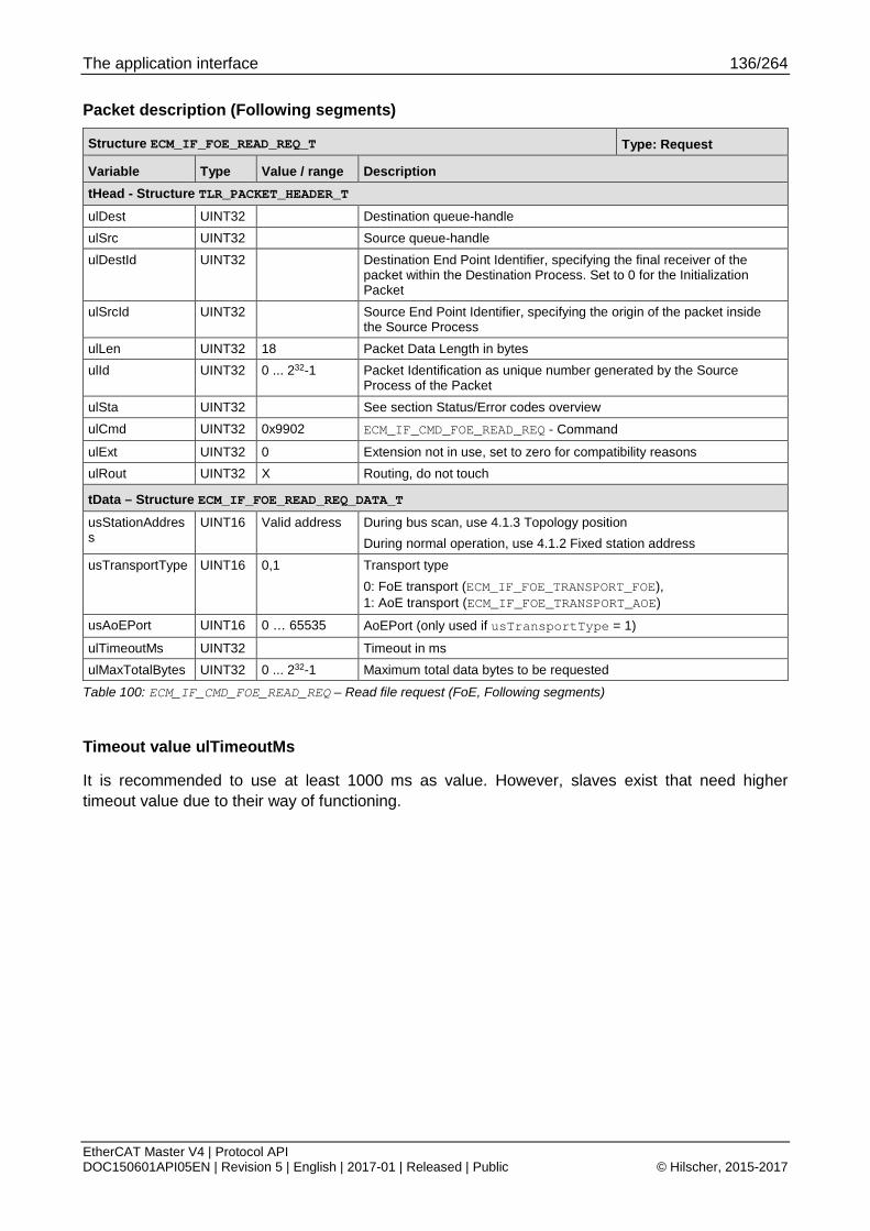
The application interface 136/264
EtherCAT Master V4 | Protocol API DOC150601API05EN | Revision 5 | English | 2017-01 | Released | Public © Hilscher, 2015-2017
Packet description (Following segments)
Structure ECM_IF_FOE_READ_REQ_T Type: Request
Variable Type Value / range Description tHead - Structure TLR_PACKET_HEADER_T ulDest UINT32 Destination queue-handle ulSrc UINT32 Source queue-handle ulDestId UINT32 Destination End Point Identifier, specifying the final receiver of the
packet within the Destination Process. Set to 0 for the Initialization Packet
ulSrcId UINT32 Source End Point Identifier, specifying the origin of the packet inside the Source Process
ulLen UINT32 18 Packet Data Length in bytes ulId UINT32 0 ... 232-1 Packet Identification as unique number generated by the Source
Process of the Packet ulSta UINT32 See section Status/Error codes overview ulCmd UINT32 0x9902 ECM_IF_CMD_FOE_READ_REQ - Command
ulExt UINT32 0 Extension not in use, set to zero for compatibility reasons ulRout UINT32 X Routing, do not touch
tData – Structure ECM_IF_FOE_READ_REQ_DATA_T usStationAddress
UINT16 Valid address During bus scan, use 4.1.3 Topology position During normal operation, use 4.1.2 Fixed station address
usTransportType UINT16 0,1 Transport type 0: FoE transport (ECM_IF_FOE_TRANSPORT_FOE), 1: AoE transport (ECM_IF_FOE_TRANSPORT_AOE)
usAoEPort UINT16 0 … 65535 AoEPort (only used if usTransportType = 1)
ulTimeoutMs UINT32 Timeout in ms ulMaxTotalBytes UINT32 0 ... 232-1 Maximum total data bytes to be requested
Table 100: ECM_IF_CMD_FOE_READ_REQ – Read file request (FoE, Following segments)
Timeout value ulTimeoutMs
It is recommended to use at least 1000 ms as value. However, slaves exist that need higher timeout value due to their way of functioning.

The application interface 137/264
EtherCAT Master V4 | Protocol API DOC150601API05EN | Revision 5 | English | 2017-01 | Released | Public © Hilscher, 2015-2017
Packet structure reference typedef struct ECM_IF_FOE_READ_CNF_DATA_Ttag { uint16_t usStationAddress; uint16_t usTransportType; uint16_t usAoEPort; uint32_t ulTimeoutMs; uint32_t ulTotalBytes; uint8_t abData[1024]; } ECM_IF_FOE_READ_CNF_DATA_T; typedef struct ECM_IF_FOE_READ_CNF_Ttag { TLR_PACKET_HEADER_T tHead; ECM_IF_FOE_READ_CNF_DATA_T tData; } ECM_IF_FOE_READ_CNF_T;
Packet description
Structure ECM_IF_FOE_READ_CNF_T Type: Confirmation
Variable Type Value / range
Description
tHead - Structure TLR_PACKET_HEADER_T
ulDest UINT32 Destination queue handle, unchanged ulSrc UINT32 Source queue handle, unchanged ulDestId UINT32 Destination End Point Identifier, specifying the final receiver of the packet
within the Destination Process. Set to 0 for the Initialization Packet ulSrcId UINT32 Source End Point Identifier, specifying the origin of the packet inside the
Source Process ulLen UINT32 14 + n Packet Data Length in bytes ulId UINT32 0 ... 232-1 Packet Identification, unchanged ulSta UINT32 See section Status/Error codes overview ulCmd UINT32 0x9903 ECM_IF_CMD_FOE_READ_CNF – Command
ulExt UINT32 0 Extension, reserved ulRout UINT32 x Routing information, do not change
tData – Structure ECM_IF_FOE_READ_CNF_DATA_T usStationAddress
UINT16 Valid address
Value from request
usTransportType
UINT16 0,1 Value from request
usAoEPort UINT16 Value from request ulTimeoutMs UINT32 Timeout in ms ulTotalBytes UINT32 Summed length of all abData of all fragments abData[n] UINT8[] Data of a fragment. Actual byte length is given as ulLen – 14
In case of ulSta != 0, it optionally contains a NUL-terminated error message.
Table 101: ECM_IF_CMD_FOE_READ_CNF – Read file confirmation (FoE)
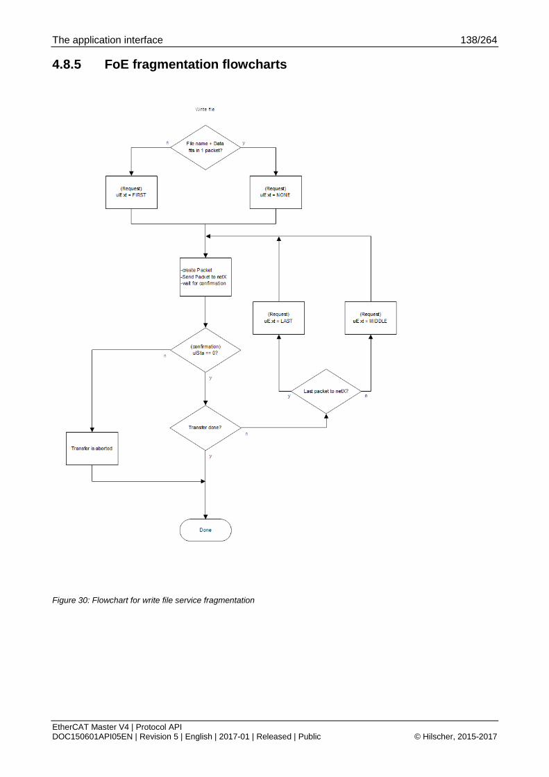
The application interface 138/264
EtherCAT Master V4 | Protocol API DOC150601API05EN | Revision 5 | English | 2017-01 | Released | Public © Hilscher, 2015-2017
4.8.5 FoE fragmentation flowcharts
Figure 30: Flowchart for write file service fragmentation

The application interface 139/264
EtherCAT Master V4 | Protocol API DOC150601API05EN | Revision 5 | English | 2017-01 | Released | Public © Hilscher, 2015-2017
Figure 31: Flowchart for read file fragmentation

The application interface 140/264
EtherCAT Master V4 | Protocol API DOC150601API05EN | Revision 5 | English | 2017-01 | Released | Public © Hilscher, 2015-2017
4.9 SoE services
4.9.1 Slave state accessibility SoE access is possible in the following slave states if supported by slave:
PREOP
SAFEOP
OP
Slaves may limit access depending on slave state to certain objects.
4.9.2 Fragmentation of write IDN (SoE) Flow charts are presented in chapter 4.9.5 SoE fragmentation flowcharts.
When the data fits into a single fragment, the following sequence is used:
Figure 32: Single fragment handling of write IDN service
When two or more fragments are required for the transfer, the following sequence diagrams apply:
Figure 33: Two Fragment handling of write IDN service

The application interface 141/264
EtherCAT Master V4 | Protocol API DOC150601API05EN | Revision 5 | English | 2017-01 | Released | Public © Hilscher, 2015-2017
Figure 34: Multiple fragment handling of write IDN service

The application interface 142/264
EtherCAT Master V4 | Protocol API DOC150601API05EN | Revision 5 | English | 2017-01 | Released | Public © Hilscher, 2015-2017
4.9.3 Fragmentation of read IDN (SoE) Flow charts are presented in chapter 4.9.5 SoE fragmentation flowcharts.
When the data fit into a single fragment, the following sequence is used:
Figure 35: Single fragment handling of read IDN service
When two or more fragments are required for the transfer, the following sequence diagrams apply:
Figure 36: Two fragment handling of read IDN service

The application interface 143/264
EtherCAT Master V4 | Protocol API DOC150601API05EN | Revision 5 | English | 2017-01 | Released | Public © Hilscher, 2015-2017
Figure 37: Multiple fragment handling of read IDN service

The application interface 144/264
EtherCAT Master V4 | Protocol API DOC150601API05EN | Revision 5 | English | 2017-01 | Released | Public © Hilscher, 2015-2017
4.9.4 Packets
4.9.4.1 Write IDN (SoE)
The following addressing schemes are used:
During generic bus network, use 4.1.3 Topology position
During normal operation, use 4.1.2 Fixed station address
ulDestId has to be handled as follows:
First fragment has ulDestId == 0
Stack returns first fragment confirmation with ulDestId != 0
This ulDestId has to be provided to all subsequent fragments
Packet structure reference typedef struct ECM_IF_SOE_WRITE_REQ_DATA_Ttag { uint16_t usStationAddress; uint16_t usTransportType; uint16_t usAoEPort; uint16_t usIDN; uint32_t ulTotalBytes; uint32_t ulTimeoutMs; uint8_t bDriveNo; uint8_t bElementFlags; uint8_t abData[1024]; } ECM_IF_SOE_WRITE_REQ_DATA_T; typedef struct ECM_IF_SOE_WRITE_REQ_Ttag { TLR_PACKET_HEADER_T tHead; ECM_IF_SOE_WRITE_REQ_DATA_T tData; } ECM_IF_SOE_WRITE_REQ_T;

The application interface 145/264
EtherCAT Master V4 | Protocol API DOC150601API05EN | Revision 5 | English | 2017-01 | Released | Public © Hilscher, 2015-2017
Packet description
Structure ECM_IF_SOE_WRITE_REQ_T Type: Request
Variable Type Value / range Description tHead - Structure TLR_PACKET_HEADER_T ulDest UINT32 Destination queue-handle ulSrc UINT32 Source queue-handle ulDestId UINT32 Destination End Point Identifier, specifying the final receiver of the
packet within the Destination Process. Set to 0 for the Initialization Packet
ulSrcId UINT32 Source End Point Identifier, specifying the origin of the packet inside the Source Process
ulLen UINT32 18 + n Packet Data Length in bytes ulId UINT32 0 ... 232-1 Packet Identification as unique number generated by the Source
Process of the Packet ulSta UINT32 See section Status/Error codes overview ulCmd UINT32 0x9B00 ECM_IF_CMD_SOE_WRITE_REQ - Command
ulExt UINT32 0 Extension not in use, set to zero for compatibility reasons ulRout UINT32 X Routing, do not touch
tData – Structure ECM_IF_SOE_WRITE_REQ_DATA_T usStationAddress UINT16 Valid address During bus scan, use 4.1.3 Topology position
During normal operation, use 4.1.2 Fixed station address usTransportType UINT16 0,1 Transport type
0: SoE transport (ECM_IF_SOE_TRANSPORT_SOE), 1: AoE transport (ECM_IF_SOE_TRANSPORT_AOE)
usAoEPort UINT16 0 … 65535 AoEPort (only used if usTransportType = 1)
usIDN UINT16 Valid IDN IDN number ulTotalBytes UINT32 0 ... 232-1 Summed length of all abData of all fragments
ulTimeoutMs UINT32 Timeout in ms bDriveNo UINT8 0 … 7 Drive number bElementFlags UINT8 0 … 255 See Table 103: Meaning of bElementFlags below
abData[n] UINT8[] Data of a fragment. Actual byte length is given as ulLen - 18
Table 102: ECM_IF_CMD_SOE_WRITE_REQ – Write IDN request
Timeout value ulTimeoutMs
It is recommended to use at least 1000 ms as value. However, slaves exist that need higher timeout value due to their way of functioning.
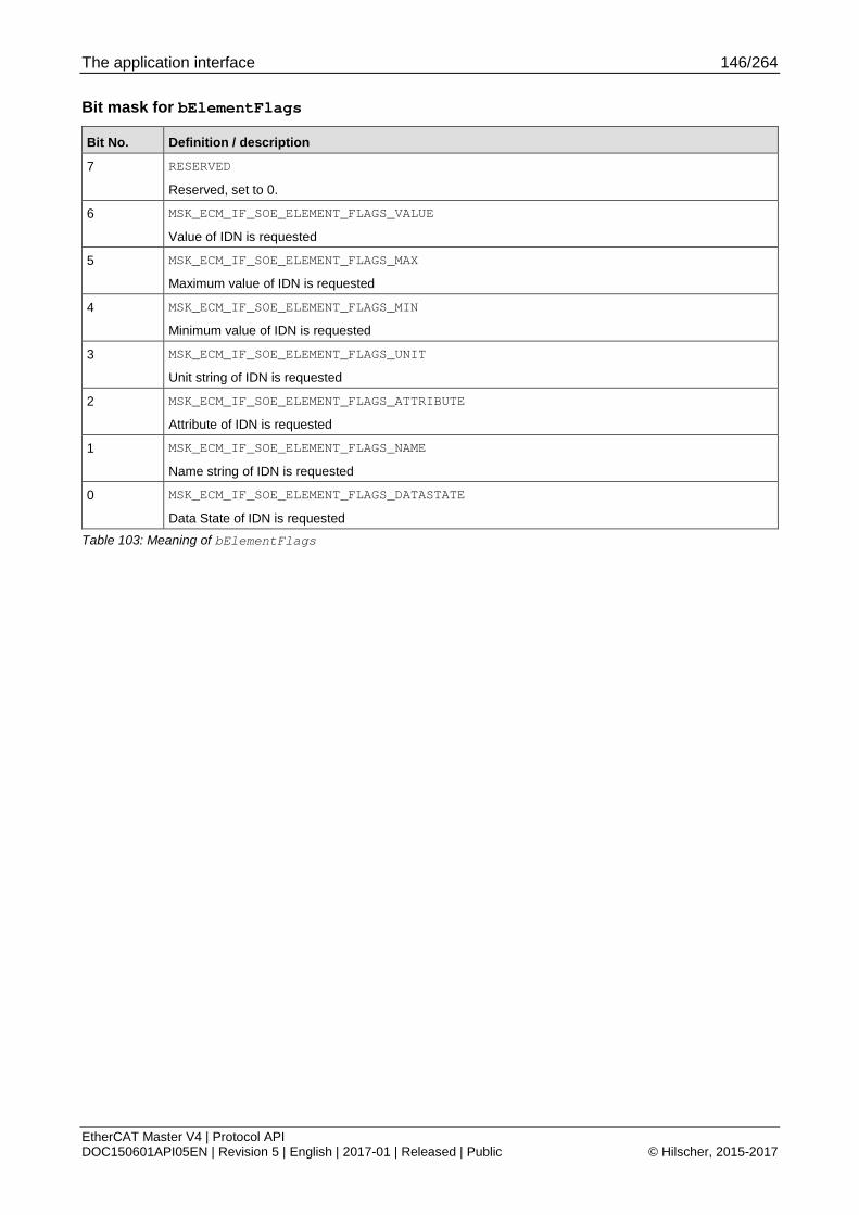
The application interface 146/264
EtherCAT Master V4 | Protocol API DOC150601API05EN | Revision 5 | English | 2017-01 | Released | Public © Hilscher, 2015-2017
Bit mask for bElementFlags
Bit No. Definition / description
7 RESERVED
Reserved, set to 0.
6 MSK_ECM_IF_SOE_ELEMENT_FLAGS_VALUE
Value of IDN is requested
5 MSK_ECM_IF_SOE_ELEMENT_FLAGS_MAX
Maximum value of IDN is requested
4 MSK_ECM_IF_SOE_ELEMENT_FLAGS_MIN
Minimum value of IDN is requested
3 MSK_ECM_IF_SOE_ELEMENT_FLAGS_UNIT
Unit string of IDN is requested
2 MSK_ECM_IF_SOE_ELEMENT_FLAGS_ATTRIBUTE
Attribute of IDN is requested
1 MSK_ECM_IF_SOE_ELEMENT_FLAGS_NAME
Name string of IDN is requested
0 MSK_ECM_IF_SOE_ELEMENT_FLAGS_DATASTATE
Data State of IDN is requested
Table 103: Meaning of bElementFlags

The application interface 147/264
EtherCAT Master V4 | Protocol API DOC150601API05EN | Revision 5 | English | 2017-01 | Released | Public © Hilscher, 2015-2017
Packet structure reference typedef struct ECM_IF_SOE_WRITE_CNF_DATA_Ttag { uint16_t usStationAddress; uint16_t usTransportType; uint16_t usAoEPort; uint16_t usIDN; uint32_t ulTotalBytes; uint32_t ulTimeoutMs; uint8_t bDriveNo; uint8_t bElementFlags; } ECM_IF_SOE_WRITE_CNF_DATA_T; typedef struct ECM_IF_SOE_WRITE_CNF_Ttag { TLR_PACKET_HEADER_T tHead; ECM_IF_SOE_WRITE_CNF_DATA_T tData; } ECM_IF_SOE_WRITE_CNF_T;
Packet description
Structure ECM_IF_SOE_WRITE_CNF_T Type: Confirmation
Variable Type Value / range Description tHead - Structure TLR_PACKET_HEADER_T ulDest UINT32 Destination queue handle, unchanged ulSrc UINT32 Source queue handle, unchanged ulDestId UINT32 Destination End Point Identifier, specifying the final receiver of the packet
within the Destination Process. Set to 0 for the Initialization Packet
ulSrcId UINT32 Source End Point Identifier, specifying the origin of the packet inside the Source Process
ulLen UINT32 18 Packet Data Length in bytes ulId UINT32 0 ... 232-1 Packet Identification, unchanged ulSta UINT32 See section Status/Error codes overview ulCmd UINT32 0x9B01 ECM_IF_CMD_SOE_WRITE_CNF – Command
ulExt UINT32 0 Extension, reserved ulRout UINT32 x Routing information, do not change
tData – Structure ECM_IF_SOE_WRITE_CNF_DATA_T usStationAddress
UINT16 Valid address Value from request
usTransportType
UINT16 0,1 Value from request
usAoEPort UINT16 Value from request usIDN UINT16 Valid IDN Value from request ulTotalBytes UINT32 Value from request ulTimeoutMs UINT32 Value from request bDriveNo UINT8 0 … 7 Value from request bElementFlags UINT8 0 … 255 Value from request
Table 104: ECM_IF_CMD_SOE_WRITE_CNF – Write IDN confirmation
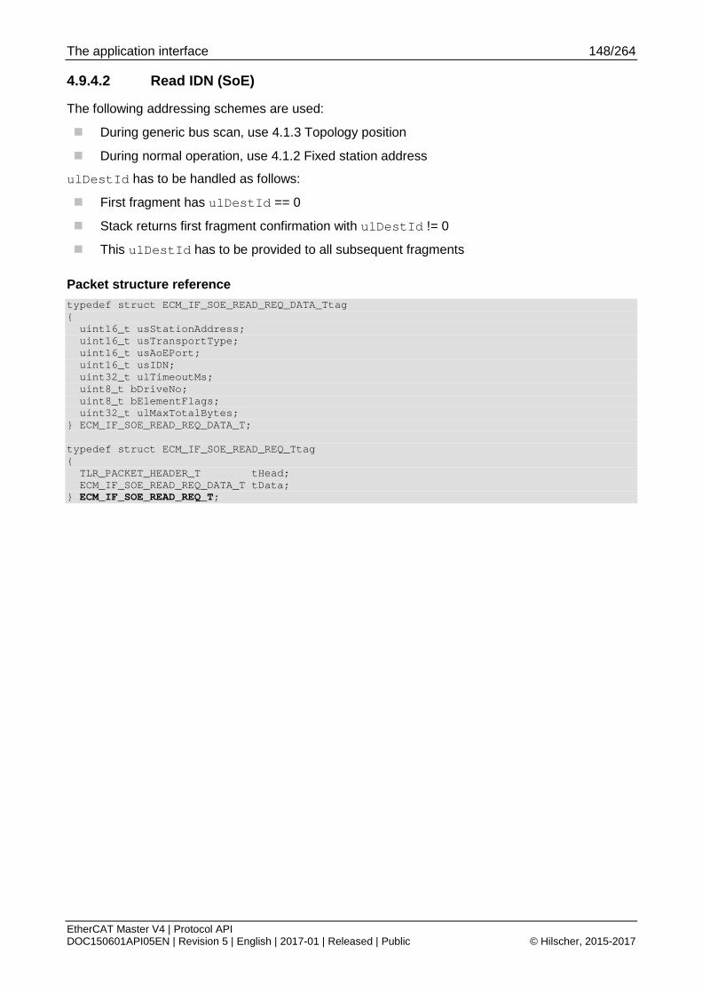
The application interface 148/264
EtherCAT Master V4 | Protocol API DOC150601API05EN | Revision 5 | English | 2017-01 | Released | Public © Hilscher, 2015-2017
4.9.4.2 Read IDN (SoE)
The following addressing schemes are used:
During generic bus scan, use 4.1.3 Topology position
During normal operation, use 4.1.2 Fixed station address
ulDestId has to be handled as follows:
First fragment has ulDestId == 0
Stack returns first fragment confirmation with ulDestId != 0
This ulDestId has to be provided to all subsequent fragments
Packet structure reference typedef struct ECM_IF_SOE_READ_REQ_DATA_Ttag { uint16_t usStationAddress; uint16_t usTransportType; uint16_t usAoEPort; uint16_t usIDN; uint32_t ulTimeoutMs; uint8_t bDriveNo; uint8_t bElementFlags; uint32_t ulMaxTotalBytes; } ECM_IF_SOE_READ_REQ_DATA_T; typedef struct ECM_IF_SOE_READ_REQ_Ttag { TLR_PACKET_HEADER_T tHead; ECM_IF_SOE_READ_REQ_DATA_T tData; } ECM_IF_SOE_READ_REQ_T;

The application interface 149/264
EtherCAT Master V4 | Protocol API DOC150601API05EN | Revision 5 | English | 2017-01 | Released | Public © Hilscher, 2015-2017
Packet description
Structure ECM_IF_SOE_READ_REQ_T Type: Request
Variable Type Value / range Description tHead - Structure TLR_PACKET_HEADER_T ulDest UINT32 Destination queue-handle ulSrc UINT32 Source queue-handle ulDestId UINT32 Destination End Point Identifier, specifying the final receiver of the
packet within the Destination Process. Set to 0 for the Initialization Packet
ulSrcId UINT32 Source End Point Identifier, specifying the origin of the packet inside the Source Process
ulLen UINT32 18 Packet Data Length in bytes ulId UINT32 0 ... 232-1 Packet Identification as unique number generated by the Source
Process of the Packet ulSta UINT32 See section Status/Error codes overview ulCmd UINT32 0x9B02 ECM_IF_CMD_SOE_READ_REQ - Command
ulExt UINT32 0 Extension not in use, set to zero for compatibility reasons ulRout UINT32 X Routing, do not touch
tData – Structure ECM_IF_SOE_READ_REQ_DATA_T usStationAddress
UINT16 Valid address During bus scan, use 4.1.3 Topology position During normal operation, use 4.1.2 Fixed station address
usTransportType UINT16 0,1 Transport type 0: SoE transport (ECM_IF_SOE_TRANSPORT_SOE), 1: AoE transport (ECM_IF_SOE_TRANSPORT_AOE)
usAoEPort UINT16 0 … 65535 AoEPort (only used if usTransportType = 1)
usIDN UINT16 Valid IDN IDN number ulTimeoutMs UINT32 Timeout in ms bDriveNo UINT8 0 … 7 Drive number bElementFlags UINT8 0 … 255 See table below ulMaxTotalBytes UINT32 0 ... 232-1 Maximum total data bytes to be requested
Table 105: ECM_IF_CMD_SOE_READ_REQ – Read IDN request
Timeout value ulTimeoutMs
It is recommended to use at least 1000 ms as value. However, slaves exist that need higher timeout value due to their way of functioning.

The application interface 150/264
EtherCAT Master V4 | Protocol API DOC150601API05EN | Revision 5 | English | 2017-01 | Released | Public © Hilscher, 2015-2017
Bit mask for bElementFlags
Bit No. Definition / description
7 RESERVED
Reserved, set to 0.
6 MSK_ECM_IF_SOE_ELEMENT_FLAGS_VALUE
Value of IDN is requested
5 MSK_ECM_IF_SOE_ELEMENT_FLAGS_MAX
Maximum value of IDN is requested
4 MSK_ECM_IF_SOE_ELEMENT_FLAGS_MIN
Minimum value of IDN is requested
3 MSK_ECM_IF_SOE_ELEMENT_FLAGS_UNIT
Unit string of IDN is requested
2 MSK_ECM_IF_SOE_ELEMENT_FLAGS_ATTRIBUTE
Attribute of IDN is requested
1 MSK_ECM_IF_SOE_ELEMENT_FLAGS_NAME
Name string of IDN is requested
0 MSK_ECM_IF_SOE_ELEMENT_FLAGS_DATASTATE
Data State of IDN is requested
Table 106: Meaning of bElementFlags

The application interface 151/264
EtherCAT Master V4 | Protocol API DOC150601API05EN | Revision 5 | English | 2017-01 | Released | Public © Hilscher, 2015-2017
Packet structure reference typedef struct ECM_IF_SOE_READ_CNF_DATA_Ttag { uint16_t usStationAddress; uint16_t usTransportType; uint16_t usAoEPort; uint16_t usIDN; uint32_t ulTimeoutMs; uint8_t bDriveNo; uint8_t bElementFlags; uint32_t ulTotalBytes; uint8_t abData[1024]; } ECM_IF_SOE_READ_CNF_DATA_T; typedef struct ECM_IF_SOE_READ_CNF_Ttag { TLR_PACKET_HEADER_T tHead; ECM_IF_SOE_READ_CNF_DATA_T tData; } ECM_IF_SOE_READ_CNF_T;
Packet description
Structure ECM_IF_SOE_READ_CNF_T Type: Confirmation
Variable Type Value / range
Description
tHead - Structure TLR_PACKET_HEADER_T
ulDest UINT32 Destination queue handle, unchanged ulSrc UINT32 Source queue handle, unchanged ulDestId UINT32 Destination End Point Identifier, specifying the final receiver of the packet
within the Destination Process. Set to 0 for the Initialization Packet ulSrcId UINT32 Source End Point Identifier, specifying the origin of the packet inside the
Source Process ulLen UINT32 18 + n Packet Data Length in bytes ulId UINT32 0 ... 232-1 Packet Identification, unchanged ulSta UINT32 See section Status/Error codes overview ulCmd UINT32 0x9B03 ECM_IF_CMD_SOE_READ_CNF – Command
ulExt UINT32 0 Extension, reserved ulRout UINT32 x Routing information, do not change
tData – Structure ECM_IF_SOE_READ_CNF_DATA_T usStationAddress
UINT16 Valid address
Value from request
usTransportType
UINT16 0,1 Value from request
usAoEPort UINT16 Value from request usIDN UINT16 Valid IDN Value from request ulTimeoutMs UINT32 Timeout in ms bDriveNo UINT8 0 … 7 Value from request bElementFlags UINT8 0 … 255 Value from request ulTotalBytes UINT32 Summed length of all abData of all fragments abData[n] UINT8[] Data of a fragment. Actual byte length is given as ulLen - 18
Table 107: ECM_IF_CMD_SOE_READ_CNF – Read IDN confirmation
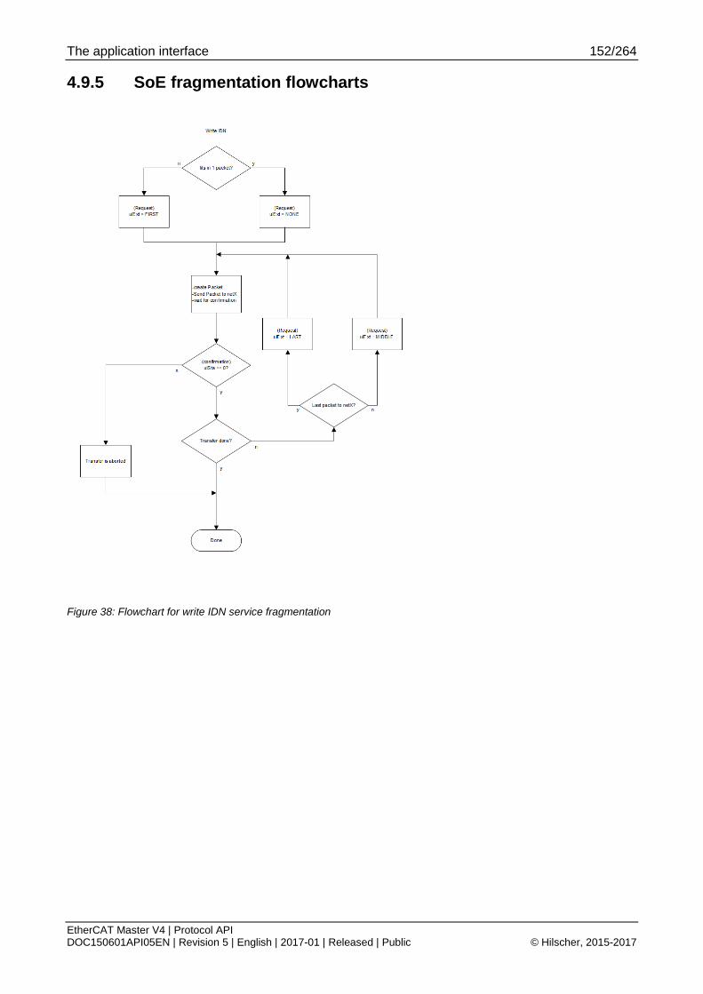
The application interface 152/264
EtherCAT Master V4 | Protocol API DOC150601API05EN | Revision 5 | English | 2017-01 | Released | Public © Hilscher, 2015-2017
4.9.5 SoE fragmentation flowcharts
Figure 38: Flowchart for write IDN service fragmentation
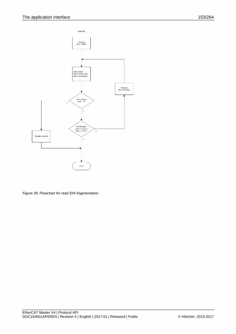
The application interface 153/264
EtherCAT Master V4 | Protocol API DOC150601API05EN | Revision 5 | English | 2017-01 | Released | Public © Hilscher, 2015-2017
Figure 39: Flowchart for read IDN fragmentation

The application interface 154/264
EtherCAT Master V4 | Protocol API DOC150601API05EN | Revision 5 | English | 2017-01 | Released | Public © Hilscher, 2015-2017
4.10 Distributed Clocks diagnostics
4.10.1 Packets
4.10.1.1 Get DC deviation information
This packet provides access to DC diagnostics. This includes maximum values that are recorded master-internally every ARMW/FRMW cycle.
The update rate of ulDcSlaveBrdDeviationSignMag depends on whether a BRD for DCSystimeDiff is configured cyclically. If it is not cyclically configured, it is requested acyclically based on calling this packet. If it is cyclically configured, it is updated every cycle which contains the actual BRD.
The maximum values can be reset with the packet 4.10.1.2 Reset DC max deviations information.
In addition, the master resets those maximum values on resynchronization of DC slaves.
Packet structure reference typedef struct ECM_IF_GET_DC_DEVIATION_REQ_Ttag { TLR_PACKET_HEADER_T tHead; } ECM_IF_GET_DC_DEVIATION_REQ_T;
Packet description
Structure ECM_IF_GET_DC_DEVIATION_REQ_T Type: Request
Variable Type Value / range Description tHead - Structure TLR_PACKET_HEADER_T ulDest UINT32 Destination queue-handle ulSrc UINT32 Source queue-handle ulDestId UINT32 Destination End Point Identifier, specifying the final receiver of the
packet within the Destination Process. Set to 0 for the Initialization Packet
ulSrcId UINT32 Source End Point Identifier, specifying the origin of the packet inside the Source Process
ulLen UINT32 0 Packet Data Length in bytes ulId UINT32 0 ... 232-1 Packet Identification as unique number generated by the Source
Process of the Packet ulSta UINT32 See section Status/Error codes overview ulCmd UINT32 0x9E60 ECM_IF_CMD_GET_DC_DEVIATION_REQ - Command
ulExt UINT32 0 Extension not in use, set to zero for compatibility reasons ulRout UINT32 X Routing, do not touch
Table 108: ECM_IF_CMD_GET_DC_DEVIATION_REQ – Get DC deviation information request
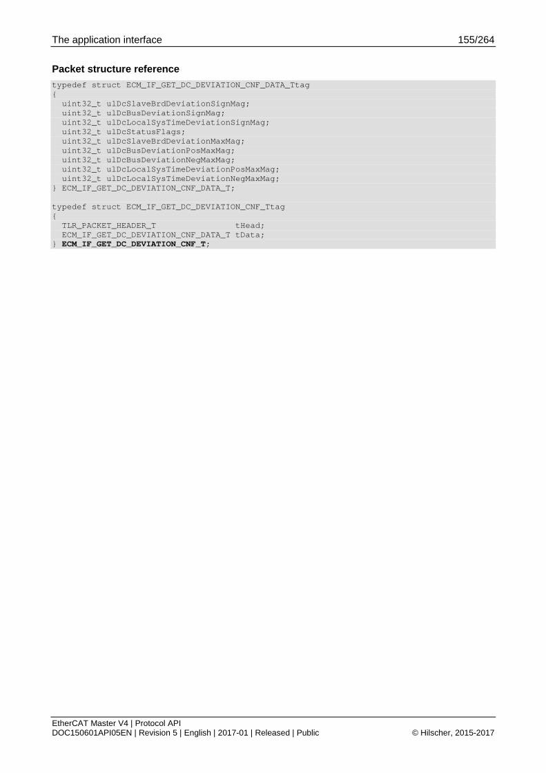
The application interface 155/264
EtherCAT Master V4 | Protocol API DOC150601API05EN | Revision 5 | English | 2017-01 | Released | Public © Hilscher, 2015-2017
Packet structure reference typedef struct ECM_IF_GET_DC_DEVIATION_CNF_DATA_Ttag { uint32_t ulDcSlaveBrdDeviationSignMag; uint32_t ulDcBusDeviationSignMag; uint32_t ulDcLocalSysTimeDeviationSignMag; uint32_t ulDcStatusFlags; uint32_t ulDcSlaveBrdDeviationMaxMag; uint32_t ulDcBusDeviationPosMaxMag; uint32_t ulDcBusDeviationNegMaxMag; uint32_t ulDcLocalSysTimeDeviationPosMaxMag; uint32_t ulDcLocalSysTimeDeviationNegMaxMag; } ECM_IF_GET_DC_DEVIATION_CNF_DATA_T; typedef struct ECM_IF_GET_DC_DEVIATION_CNF_Ttag { TLR_PACKET_HEADER_T tHead; ECM_IF_GET_DC_DEVIATION_CNF_DATA_T tData; } ECM_IF_GET_DC_DEVIATION_CNF_T;

The application interface 156/264
EtherCAT Master V4 | Protocol API DOC150601API05EN | Revision 5 | English | 2017-01 | Released | Public © Hilscher, 2015-2017
Packet description
Structure ECM_IF_GET_DC_DEVIATION_CNF_T Type: Confirmation
Variable Type Value / range Description tHead - Structure TLR_PACKET_HEADER_T ulDest UINT32 Destination queue handle, unchanged ulSrc UINT32 Source queue handle, unchanged ulDestId UINT32 Destination End Point Identifier, specifying the final receiver of the packet
within the Destination Process. Set to 0 for the Initialization Packet
ulSrcId UINT32 Source End Point Identifier, specifying the origin of the packet inside the Source Process
ulLen UINT32 36 Packet Data Length in bytes ulId UINT32 0 ... 232-1 Packet Identification, unchanged ulSta UINT32 See section Status/Error codes overview ulCmd UINT32 0x9E61 ECM_IF_CMD_GET_DC_DEVIATION_CNF – Command
ulExt UINT32 0 Extension, reserved ulRout UINT32 x Routing information, do not change
tData – Structure ECM_IF_GET_DC_DEVIATION_CNF_DATA_T ulDcSlaveBrdDeviationSignMag
UINT32 Bitwise OR-related value of SysTimeDifference registers of all connected DC capable slaves
ulDcBusDeviationSignMag
UINT32 Deviation of Bus Cycle generator towards bus cycle For definition of Sign/Magnitude values see table below.
ulDcLocalSysTimeDeviationSignMag
UINT32 Deviation of master SysTime unit in relation to Bus Cycle For definition of Sign/Magnitude values see table below
ulDcStatusFlags
UINT32 DC Status flags See Table 110: Meaning of ulDcStatusFlags below
ulDcSlaveBrdDeviationMaxMag
UINT32 Max deviation seen in ulDcSlaveBrdDeviationSignMag
ulDcBusDeviationPosMaxMag
UINT32 Max. positive deviation seen in ulDcBusDeviationSignMag
ulDcBusDeviationNegMaxMag
UINT32 Max. negative deviation seen in ulDcBusDeviationSignMag
ulDcLocalSysTimeDeviationPosMaxMag
UINT32 Max. positive deviation seen in ulDcLocalSysTimeDeviationSignMag
ulDcLocalSysTimeDeviationNegMaxMag
UINT32 Max. negative deviation seen in ulDcLocalSysTimeDeviationSignMag
Table 109: ECM_IF_CMD_GET_DC_DEVIATION_CNF – Get DC deviation information confirmation

The application interface 157/264
EtherCAT Master V4 | Protocol API DOC150601API05EN | Revision 5 | English | 2017-01 | Released | Public © Hilscher, 2015-2017
Bit mask for ulDcStatusFlags
Bit No. Definition / description
31-7 RESERVED
Reserved, set to 0.
6 ECM_IF_DC_CONTROL_STATUS_STOPPED_DC_ALL_PORTS_RX_STATUS_TIMEOUT
If this bit is set, the sending of ARMW/FRMW has been stopped due to no frames being received.
5 ECM_IF_DC_CONTROL_STATUS_STOPPED_DL_STATUS_IRQ
If this bit is set, the sending of ARMW/FRMW has been stopped due to a slave signaling a DL status change.
4 ECM_IF_DC_CONTROL_STATUS_STOPPED_EXPECTED_BRD_ALSTATUS_WKC_RED
If this bit is set, the sending of ARMW/FRMW has been stopped due to unexpected working counter on redundancy channel.
3 ECM_IF_DC_CONTROL_STATUS_STOPPED_EXPECTED_BRD_ALSTATUS_WKC_MAIN
If this bit is set, the sending of ARMW/FRMW has been stopped due to unexpected working counter on main channel.
2 ECM_IF_DC_CONTROL_STATUS_STOPPED_EXPECTED_DC_RX_STATUS_RED
If this bit is set, the sending of ARMW/FRMW has been stopped due to unexpected received frame source (main,red) on redundancy port.
1 ECM_IF_DC_CONTROL_STATUS_STOPPED_EXPECTED_DC_RX_STATUS_MAIN
If this bit is set, the sending of ARMW/FRMW has been stopped due to unexpected received frame source (main,red) on main port.
0 ECM_IF_DC_CONTROL_STATUS_ACTIVE
If this bit is set, the sending of ARMW/FRMW status is active.
Table 110: Meaning of ulDcStatusFlags
Definition of sign/magnitude values
Bit No. Definition / description
31 Sign of difference
If set, the magnitude has to be considered as negative value.
30-0 Magnitude of difference in ns (unsigned int) Table 111: Meaning of sign/magnitude values

The application interface 158/264
EtherCAT Master V4 | Protocol API DOC150601API05EN | Revision 5 | English | 2017-01 | Released | Public © Hilscher, 2015-2017
4.10.1.2 Reset DC max deviations information
Packet structure reference typedef struct ECM_IF_RESET_DC_MAX_DEVIATIONS_REQ_Ttag { TLR_PACKET_HEADER_T tHead; } ECM_IF_RESET_DC_MAX_DEVIATIONS_REQ_T;
Packet description
Structure ECM_IF_RESET_DC_MAX_DEVIATIONS_REQ_T Type: Request
Variable Type Value / range Description tHead - Structure TLR_PACKET_HEADER_T
ulDest UINT32 Destination queue-handle ulSrc UINT32 Source queue-handle ulDestId UINT32 Destination End Point Identifier, specifying the final receiver of the
packet within the Destination Process. Set to 0 for the Initialization Packet
ulSrcId UINT32 Source End Point Identifier, specifying the origin of the packet inside the Source Process
ulLen UINT32 0 Packet Data Length in bytes ulId UINT32 0 ... 232-1 Packet Identification as unique number generated by the Source
Process of the Packet ulSta UINT32 See section Status/Error codes overview ulCmd UINT32 0x9E64 ECM_IF_CMD_RESET_DC_MAX_DEVIATIONS_REQ - Command
ulExt UINT32 0 Extension not in use, set to zero for compatibility reasons ulRout UINT32 X Routing, do not touch
Table 112: ECM_IF_CMD_RESET_DC_MAX_DEVIATIONS_REQ – Reset DC max deviations request

The application interface 159/264
EtherCAT Master V4 | Protocol API DOC150601API05EN | Revision 5 | English | 2017-01 | Released | Public © Hilscher, 2015-2017
Packet structure reference typedef struct ECM_IF_RESET_DC_MAX_DEVIATIONS_CNF_Ttag { TLR_PACKET_HEADER_T tHead; } ECM_IF_RESET_DC_MAX_DEVIATIONS_CNF_T;
Packet description
Structure ECM_IF_RESET_DC_MAX_DEVIATIONS_CNF_T Type: Confirmation
Variable Type Value / range Description tHead - Structure TLR_PACKET_HEADER_T
ulDest UINT32 Destination queue handle, unchanged ulSrc UINT32 Source queue handle, unchanged ulDestId UINT32 Destination End Point Identifier, specifying the final receiver of the packet
within the Destination Process. Set to 0 for the Initialization Packet ulSrcId UINT32 Source End Point Identifier, specifying the origin of the packet inside the
Source Process ulLen UINT32 36 Packet Data Length in bytes ulId UINT32 0 ... 232-1 Packet Identification, unchanged ulSta UINT32 See section Status/Error codes overview ulCmd UINT32 0x9E65 ECM_IF_CMD_RESET_DC_MAX_DEVIATIONS_CNF – Command
ulExt UINT32 0 Extension, reserved ulRout UINT32 x Routing information, do not change
Table 113: ECM_IF_CMD_RESET_DC_MAX_DEVIATIONS_CNF – Reset DC max deviations confirmation

The application interface 160/264
EtherCAT Master V4 | Protocol API DOC150601API05EN | Revision 5 | English | 2017-01 | Released | Public © Hilscher, 2015-2017
4.10.1.3 Get slave DC info
This packet allows reading the master known DC status of a given slave.
The following addressing schemes are used:
4.1.2 Fixed station address
Packet structure reference typedef struct ECM_IF_GET_SLAVE_DC_INFO_REQ_DATA_Ttag { uint16_t usStationAddress; } ECM_IF_GET_SLAVE_DC_INFO_REQ_DATA_T; typedef struct ECM_IF_GET_SLAVE_DC_INFO_REQ_Ttag { TLR_PACKET_HEADER_T tHead; ECM_IF_GET_SLAVE_DC_INFO_REQ_DATA_T tData; } ECM_IF_GET_SLAVE_DC_INFO_REQ_T;
Packet description
Structure ECM_IF_GET_SLAVE_DC_INFO_REQ_T Type: Request
Variable Type Value / range Description tHead - Structure TLR_PACKET_HEADER_T ulDest UINT32 Destination queue-handle ulSrc UINT32 Source queue-handle ulDestId UINT32 Destination End Point Identifier, specifying the final receiver of the
packet within the Destination Process. Set to 0 for the Initialization Packet
ulSrcId UINT32 Source End Point Identifier, specifying the origin of the packet inside the Source Process
ulLen UINT32 2 Packet Data Length in bytes ulId UINT32 0 ... 232-1 Packet Identification as unique number generated by the Source
Process of the Packet ulSta UINT32 See section Status/Error codes overview ulCmd UINT32 0x9E62 ECM_IF_CMD_GET_SLAVE_DC_INFO_REQ - Command
ulExt UINT32 0 Extension not in use, set to zero for compatibility reasons ulRout UINT32 X Routing, do not touch
tData – Structure ECM_IF_GET_SLAVE_DC_INFO_REQ_DATA_T usStationAddress
UINT16 Valid address Use 4.1.2 Fixed station address
Table 114: ECM_IF_CMD_GET_SLAVE_DC_INFO_REQ – Get slave DC information request

The application interface 161/264
EtherCAT Master V4 | Protocol API DOC150601API05EN | Revision 5 | English | 2017-01 | Released | Public © Hilscher, 2015-2017
Packet structure reference typedef struct ECM_IF_GET_SLAVE_DC_INFO_CNF_DATA_Ttag { uint16_t usStationAddress; uint16_t usFlags; uint32_t ulDcSystimeDelayNs; uint64_t ullDcSystimeOffsetNs; uint64_t ullDcSyncShiftTimeNs; uint32_t ulDcCyc0Time; uint32_t ulDcCyc1Time; uint64_t ullRxLatchTime0Ns; uint32_t ulRxLatchTime1Ns; uint32_t ulRxLatchTime2Ns; uint32_t ulRxLatchTime3Ns; uint32_t ulPort1SumDelayNs; uint32_t ulPort2SumDelayNs; uint32_t ulPort3SumDelayNs; uint32_t ulTotalSumDelayNs; uint64_t ullDcSync0StartingDelayTimeNs; } ECM_IF_GET_SLAVE_DC_INFO_CNF_DATA_T; typedef struct ECM_IF_GET_SLAVE_DC_INFO_CNF_Ttag { TLR_PACKET_HEADER_T tHead; ECM_IF_GET_SLAVE_DC_INFO_CNF_DATA_T tData; } ECM_IF_GET_SLAVE_DC_INFO_CNF_T;
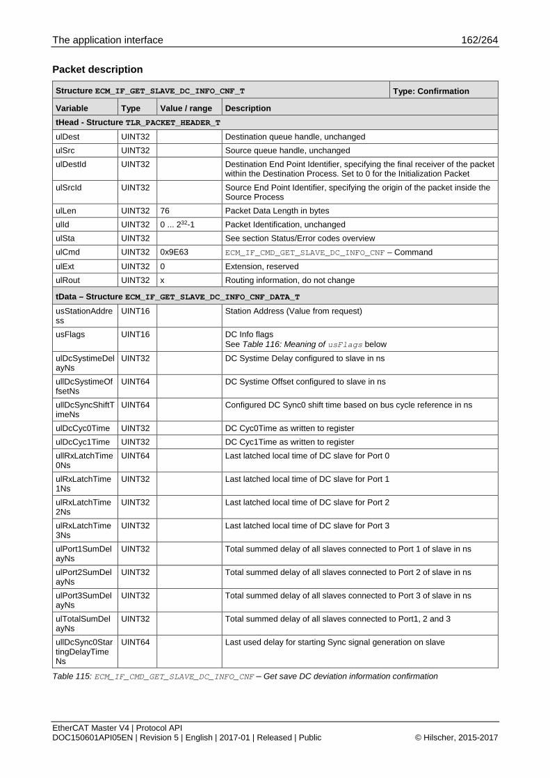
The application interface 162/264
EtherCAT Master V4 | Protocol API DOC150601API05EN | Revision 5 | English | 2017-01 | Released | Public © Hilscher, 2015-2017
Packet description
Structure ECM_IF_GET_SLAVE_DC_INFO_CNF_T Type: Confirmation
Variable Type Value / range Description tHead - Structure TLR_PACKET_HEADER_T ulDest UINT32 Destination queue handle, unchanged ulSrc UINT32 Source queue handle, unchanged ulDestId UINT32 Destination End Point Identifier, specifying the final receiver of the packet
within the Destination Process. Set to 0 for the Initialization Packet
ulSrcId UINT32 Source End Point Identifier, specifying the origin of the packet inside the Source Process
ulLen UINT32 76 Packet Data Length in bytes ulId UINT32 0 ... 232-1 Packet Identification, unchanged ulSta UINT32 See section Status/Error codes overview ulCmd UINT32 0x9E63 ECM_IF_CMD_GET_SLAVE_DC_INFO_CNF – Command
ulExt UINT32 0 Extension, reserved ulRout UINT32 x Routing information, do not change
tData – Structure ECM_IF_GET_SLAVE_DC_INFO_CNF_DATA_T usStationAddress
UINT16 Station Address (Value from request)
usFlags UINT16 DC Info flags See Table 116: Meaning of usFlags below
ulDcSystimeDelayNs
UINT32 DC Systime Delay configured to slave in ns
ullDcSystimeOffsetNs
UINT64 DC Systime Offset configured to slave in ns
ullDcSyncShiftTimeNs
UINT64 Configured DC Sync0 shift time based on bus cycle reference in ns
ulDcCyc0Time UINT32 DC Cyc0Time as written to register ulDcCyc1Time UINT32 DC Cyc1Time as written to register ullRxLatchTime0Ns
UINT64 Last latched local time of DC slave for Port 0
ulRxLatchTime1Ns
UINT32 Last latched local time of DC slave for Port 1
ulRxLatchTime2Ns
UINT32 Last latched local time of DC slave for Port 2
ulRxLatchTime3Ns
UINT32 Last latched local time of DC slave for Port 3
ulPort1SumDelayNs
UINT32 Total summed delay of all slaves connected to Port 1 of slave in ns
ulPort2SumDelayNs
UINT32 Total summed delay of all slaves connected to Port 2 of slave in ns
ulPort3SumDelayNs
UINT32 Total summed delay of all slaves connected to Port 3 of slave in ns
ulTotalSumDelayNs
UINT32 Total summed delay of all slaves connected to Port1, 2 and 3
ullDcSync0StartingDelayTimeNs
UINT64 Last used delay for starting Sync signal generation on slave
Table 115: ECM_IF_CMD_GET_SLAVE_DC_INFO_CNF – Get save DC deviation information confirmation

The application interface 163/264
EtherCAT Master V4 | Protocol API DOC150601API05EN | Revision 5 | English | 2017-01 | Released | Public © Hilscher, 2015-2017
Bit mask for usFlags
Bit No. Definition / description
15 ECM_IF_GET_SLAVE_DC_INFO_FLAGS_PORT3_EXISTS
Slave has a port 3
14 ECM_IF_GET_SLAVE_DC_INFO_FLAGS_PORT2_EXISTS
Slave has a port 2
13 ECM_IF_GET_SLAVE_DC_INFO_FLAGS_PORT1_EXISTS
Slave has a port 1
12 ECM_IF_GET_SLAVE_DC_INFO_FLAGS_PORT0_EXISTS
Slave has a port 0
11 Reserved
10 ECM_IF_GET_SLAVE_DC_INFO_FLAGS_DC_ACTIVATE_SYNC1
DC Sync1 is configured to be activated
9 ECM_IF_GET_SLAVE_DC_INFO_FLAGS_DC_ACTIVATE_SYNC0
DC Sync0 is configured to be activated
8 ECM_IF_GET_SLAVE_DC_INFO_FLAGS_DC_ACTIVATE
DC Sync Unit is configured to be activated
4 ECM_IF_GET_SLAVE_DC_INFO_FLAGS_DC_IS_SUPPORTED
Slave supports DC in general (either 32bit or 64bit)
3 ECM_IF_GET_SLAVE_DC_INFO_FLAGS_DC_IS_64BIT
Slave supports 64bit DC
2 ECM_IF_GET_SLAVE_DC_INFO_FLAGS_DC_SYNC_CONFIGURED
DC Sync Unit has been configured with parameters
1 ECM_IF_GET_SLAVE_DC_INFO_FLAGS_DC_TIME_CONFIGURED
DC SysTime has been configured on slave
0 ECM_IF_GET_SLAVE_DC_INFO_FLAGS_IN_TOPOLOGY
Slave is connected and actively participating in topology
Table 116: Meaning of usFlags

The application interface 164/264
EtherCAT Master V4 | Protocol API DOC150601API05EN | Revision 5 | English | 2017-01 | Released | Public © Hilscher, 2015-2017
4.10.2 Legacy packets
4.10.2.1 Get DC deviation (Legacy)
Note: This packet is provided for applications migrating from ECM V3.X.
Packet structure reference typedef struct ETHERCAT_MASTER_PACKET_GET_DC_DEVIATION_REQ_Ttag { TLR_PACKET_HEADER_T tHead; } ETHERCAT_MASTER_PACKET_GET_DC_DEVIATION_REQ_T;
Packet description
Structure ETHERCAT_MASTER_GET_DC_DEVIATION_REQ_T Type: Request
Variable Type Value / range Description tHead - Structure TLR_PACKET_HEADER_T
ulDest UINT32 Destination queue-handle ulSrc UINT32 Source queue-handle ulDestId UINT32 Destination End Point Identifier, specifying the final receiver of the
packet within the Destination Process. Set to 0 for the Initialization Packet
ulSrcId UINT32 Source End Point Identifier, specifying the origin of the packet inside the Source Process
ulLen UINT32 0 Packet Data Length in bytes ulId UINT32 0 ... 232-1 Packet Identification as unique number generated by the Source
Process of the Packet ulSta UINT32 See section Status/Error codes overview ulCmd UINT32 0x65001E ETHERCAT_MASTER_CMD_GET_DC_DEVIATION_REQ - Command
ulExt UINT32 0 Extension not in use, set to zero for compatibility reasons ulRout UINT32 X Routing, do not touch
Table 117: ETHERCAT_MASTER_CMD_GET_DC_DEVIATION_REQ – Get DC deviation request (Legacy)
Packet structure reference typedef struct ETHERCAT_MASTER_PACKET_GET_DC_DEVIATION_CNF_DATA_Ttag { uint32_t ulBroadcastDeviation; uint32_t aulSlaveDeviation[ETHERCAT_MASTER_GET_DC_DEVIATION_NUMOFSLAVES]; } ETHERCAT_MASTER_PACKET_GET_DC_DEVIATION_CNF_DATA_T; typedef struct ETHERCAT_MASTER_PACKET_GET_DC_DEVIATION_CNF_Ttag { TLR_PACKET_HEADER_T tHead; ETHERCAT_MASTER_PACKET_GET_DC_DEVIATION_CNF_DATA_T tData; } ETHERCAT_MASTER_PACKET_GET_DC_DEVIATION_CNF_T;

The application interface 165/264
EtherCAT Master V4 | Protocol API DOC150601API05EN | Revision 5 | English | 2017-01 | Released | Public © Hilscher, 2015-2017
Packet description
Structure ETHERCAT_MASTER_PACKET_GET_DC_DEVIATION_CNF_T Type: Confirmation
Variable Type Value / range Description tHead - Structure TLR_PACKET_HEADER_T ulDest UINT32 Destination queue handle, unchanged ulSrc UINT32 Source queue handle, unchanged ulDestId UINT32 Destination End Point Identifier, specifying the final receiver of the packet
within the Destination Process. Set to 0 for the Initialization Packet
ulSrcId UINT32 Source End Point Identifier, specifying the origin of the packet inside the Source Process
ulLen UINT32 4 + 4 * n Packet Data Length in bytes ulId UINT32 0 ... 232-1 Packet Identification, unchanged ulSta UINT32 See section Status/Error codes overview ulCmd UINT32 0x65001F ETHERCAT_MASTER_CMD_GET_DC_DEVIATION_CNF – Command
ulExt UINT32 0 Extension, reserved ulRout UINT32 x Routing information, do not change
tData – Structure ETHERCAT_MASTER_GET_DC_DEVIATION_CNF_DATA_T ulBroadcastDeviation
UINT32 Bit mask Bitwise OR-related value of SysTimeDifference registers of all connected DC capable slaves
aulSlaveDeviation[n]
UINT32[]
Slave specific deviation Table is ordered according to addressing scheme described in section 4.1.4 Device index in ascending order.
Table 118: ETHERCAT_MASTER_CMD_GET_DC_DEVIATION_CNF – Get DC deviation confirmation (Legacy)

The application interface 166/264
EtherCAT Master V4 | Protocol API DOC150601API05EN | Revision 5 | English | 2017-01 | Released | Public © Hilscher, 2015-2017
4.11 Config readout
4.11.1 Get timing information
Packet structure reference typedef struct ECM_IF_GET_TIMING_INFO_REQ_Ttag { TLR_PACKET_HEADER_T tHead; } ECM_IF_GET_TIMING_INFO_REQ_T;
Packet description
Structure ECM_IF_GET_TIMING_INFO_REQ_T Type: Request
Variable Type Value / range Description tHead - Structure TLR_PACKET_HEADER_T ulDest UINT32 Destination queue-handle ulSrc UINT32 Source queue-handle ulDestId UINT32 Destination End Point Identifier, specifying the final receiver of the
packet within the Destination Process. Set to 0 for the Initialization Packet
ulSrcId UINT32 Source End Point Identifier, specifying the origin of the packet inside the Source Process
ulLen UINT32 0 Packet Data Length in bytes ulId UINT32 0 ... 232-1 Packet Identification as unique number generated by the Source
Process of the Packet ulSta UINT32 See section Status/Error codes overview ulCmd UINT32 0x9E20 ECM_IF_CMD_GET_TIMING_INFO_REQ - Command
ulExt UINT32 0 Extension not in use, set to zero for compatibility reasons ulRout UINT32 X Routing, do not touch
Table 119: ECM_IF_CMD_GET_TIMING_INFO_REQ – Get timing information request

The application interface 167/264
EtherCAT Master V4 | Protocol API DOC150601API05EN | Revision 5 | English | 2017-01 | Released | Public © Hilscher, 2015-2017
Packet structure reference typedef struct ECM_IF_GET_TIMING_INFO_CNF_DATA_Ttag { uint32_t ulBusCycleTimeNs; uint32_t ulFrameTransmitTimeNs; uint32_t ulExpectedBusDelayNs; uint32_t ulExpectedRxEndTimeNs; uint32_t ulExpectedTxDataTimeNs; } ECM_IF_GET_TIMING_INFO_CNF_DATA_T; typedef struct ECM_IF_GET_TIMING_INFO_CNF_Ttag { TLR_PACKET_HEADER_T tHead; ECM_IF_GET_TIMING_INFO_CNF_DATA_T tData; } ECM_IF_GET_TIMING_INFO_CNF_T;
Packet description
Structure ECM_IF_GET_TIMING_INFO_CNF_T Type: Confirmation
Variable Type Value / range Description tHead - Structure TLR_PACKET_HEADER_T ulDest UINT32 Destination queue handle, unchanged ulSrc UINT32 Source queue handle, unchanged ulDestId UINT32 Destination End Point Identifier, specifying the final receiver of the packet
within the Destination Process. Set to 0 for the Initialization Packet ulSrcId UINT32 Source End Point Identifier, specifying the origin of the packet inside the
Source Process ulLen UINT32 20 Packet Data Length in bytes ulId UINT32 0 ... 232-1 Packet Identification, unchanged ulSta UINT32 See section Status/Error codes overview ulCmd UINT32 0x9E21 ECM_IF_CMD_GET_TIMING_INFO_CNF – Command
ulExt UINT32 0 Extension, reserved ulRout UINT32 X Routing information, do not change
tData – Structure ECM_IF_GET_TIMING_INFO_CNF_DATA_T ulBusCycleTimeNs
UINT32 Bit mask Bitwise OR-related value of SysTimeDifference registers of all connected DC capable slaves
ulFrameTransmitTimeNs
UINT32 Slave specific deviation (in nanoseconds) Table is ordered according to addressing scheme described in section 4.1.4 Device index in ascending order.
ulExpectedBusDelayNs
UINT32 Expected transmission time through the entire bus (in nanoseconds) i.e. delay from start of transmission to start of receive
ulExpectedRxEndTimeNs
UINT32 Time from start of bus cycle transmission until completion of receiving the bus cycle back (in nanoseconds)
ulExpectedTxDataTimeNs
UINT32 Time from start of bus cycle transmission until a new data update is expected to be signaled to stack (in nanoseconds)
Table 120: ECM_IF_CMD_GET_TIMING_INFO_CNF – Get timing information Confirmation

The application interface 168/264
EtherCAT Master V4 | Protocol API DOC150601API05EN | Revision 5 | English | 2017-01 | Released | Public © Hilscher, 2015-2017
4.11.2 Get WcState information The WcState bit is a means to determine the current status of process data area based on the current cyclic exchange working counters.
The EtherCAT master only maps WcState bits for cyclic telegram areas that are linked with process data and contain a compare value for its validity (e.g. <Cnt> tag in ENI).
4.11.2.1 Meaning of the WcState bit
The WcState bit indicates whether a related process data area is invalid.
Value Definition / description 0 Related process data is valid 1 Related process data is invalid
Table 121: Possible values of WcState bit
4.11.2.2 Ordering of entries in confirmation
The entries are in order of their appearance in the cyclic frames. The offsets within the entries specify the process data areas which are guarded by a specific WcState bit.

The application interface 169/264
EtherCAT Master V4 | Protocol API DOC150601API05EN | Revision 5 | English | 2017-01 | Released | Public © Hilscher, 2015-2017
4.11.2.3 Get WcState information packet
Packet structure reference typedef struct ECM_IF_GET_WCSTATE_INFO_REQ_DATA_Ttag { uint32_t ulEntriesStartOffset; } ECM_IF_GET_WCSTATE_INFO_REQ_DATA_T; typedef struct ECM_IF_GET_WCSTATE_INFO_REQ_Ttag { TLR_PACKET_HEADER_T tHead; ECM_IF_GET_WCSTATE_INFO_REQ_DATA_T tData; } ECM_IF_GET_WCSTATE_INFO_REQ_T;
Packet description
Structure ECM_IF_GET_WCSTATE_INFO_REQ_T Type: Request
Variable Type Value / range Description tHead - Structure TLR_PACKET_HEADER_T ulDest UINT32 Destination queue-handle ulSrc UINT32 Source queue-handle ulDestId UINT32 Destination End Point Identifier, specifying the final receiver of the
packet within the Destination Process. Set to 0 for the Initialization Packet
ulSrcId UINT32 Source End Point Identifier, specifying the origin of the packet inside the Source Process
ulLen UINT32 4 Packet Data Length in bytes ulId UINT32 0 ... 232-1 Packet Identification as unique number generated by the Source
Process of the Packet ulSta UINT32 See section Status/Error codes overview ulCmd UINT32 0x9E22 ECM_IF_CMD_GET_WC_STATE_INFO_REQ - Command
ulExt UINT32 0 Extension not in use, set to zero for compatibility reasons ulRout UINT32 X Routing, do not touch
tData – Structure ECM_IF_GET_WCSTATE_INFO_REQ_DATA_T ulEntriesStartOffset
UINT32 Start offset at which the response data has to start Needed when ulTotalEntries in confirmation is larger than the current packet length The first message is always containing 0 here.
Table 122: ECM_IF_CMD_GET_WC_STATE_INFO_REQ – Get WcState information request
WcStateBit Entry structure reference typedef struct ECM_IF_WCSTATE_INFO_ENTRY_Ttag { uint32_t ulWcStateBitPosition; uint16_t usTxImageStartByteOffset; uint16_t usRxImageStartByteOffset; uint16_t usImageByteLength; uint16_t usDirection; } ECM_IF_WCSTATE_INFO_ENTRY_T;

The application interface 170/264
EtherCAT Master V4 | Protocol API DOC150601API05EN | Revision 5 | English | 2017-01 | Released | Public © Hilscher, 2015-2017
WcStateBit Entry structure description
Structure ECM_IF_WCSTATE_INFO_ENTRY_T
Variable name Type Meaning
ulWcStateBitPosition UINT32 Bit position within Input process data image
Examples:
Value 8 defines WcState to be in byte 0 bit 0. Value 15 defines WcState to be in byte 0 bit 7.
usTxImageStartByteOffset
UINT16 Byte offset in output process data image
Valid if Bit 0 of usDirection is set
usRxImageStartByteOffset
UINT16 Byte offset in input process data image
Valid if Bit 1 of usDirection is set
usImageByteLength UINT16 Byte length of related process data images
usDirection UINT16 Bit 0: set if usTxImageStartByteOffset is valid Bit 1: set if usRxImageStartByteOffset is valid
Table 123: Structure ECM_IF_WCSTATE_INFO_ENTRY_T
Packet structure reference typedef struct ECM_IF_WCSTATE_INFO_ENTRY_Ttag { uint32_t ulWcStateBitPosition; uint16_t usTxImageStartByteOffset; uint16_t usRxImageStartByteOffset; uint16_t usImageByteLength; uint16_t usDirection; } ECM_IF_WCSTATE_INFO_ENTRY_T; enum ECM_IF_WCSTATE_DIRECTION_Etag { MSK_ECM_IF_WCSTATE_INFO_DIRECTION_TXDATA = 0x0001, MSK_ECM_IF_WCSTATE_INFO_DIRECTION_RXDATA = 0x0002 }; #define ECM_IF_MAX_WCSTATE_INFO_ENTRIES \ ((RCX_MAX_DATA_SIZE - sizeof(TLR_UINT32) * 2) / \ sizeof(ECM_IF_WCSTATE_INFO_ENTRY_T)) typedef struct ECM_IF_GET_WCSTATE_INFO_CNF_DATA_Ttag { uint32_t ulEntriesStartOffset; uint32_t ulTotalEntries; ECM_IF_WCSTATE_INFO_ENTRY_T atEntries[ECM_IF_MAX_WCSTATE_INFO_ENTRIES]; } ECM_IF_GET_WCSTATE_INFO_CNF_DATA_T; typedef struct ECM_IF_GET_WCSTATE_INFO_CNF_Ttag { TLR_PACKET_HEADER_T tHead; ECM_IF_GET_WCSTATE_INFO_CNF_DATA_T tData; } ECM_IF_GET_WCSTATE_INFO_CNF_T;

The application interface 171/264
EtherCAT Master V4 | Protocol API DOC150601API05EN | Revision 5 | English | 2017-01 | Released | Public © Hilscher, 2015-2017
Packet description
Structure ECM_IF_GET_WCSTATE_INFO_CNF_T Type: Confirmation
Variable Type Value / range Description tHead - Structure TLR_PACKET_HEADER_T ulDest UINT32 Destination queue handle, unchanged ulSrc UINT32 Source queue handle, unchanged ulDestId UINT32 Destination End Point Identifier, specifying the final receiver of the packet
within the Destination Process. Set to 0 for the Initialization Packet
ulSrcId UINT32 Source End Point Identifier, specifying the origin of the packet inside the Source Process
ulLen UINT32 8 + 12 * n Packet Data Length in bytes ulId UINT32 0 ... 232-1 Packet Identification, unchanged ulSta UINT32 See section Status/Error codes overview ulCmd UINT32 0x9E23 ECM_IF_CMD_GET_WC_STATE_INFO_CNF – Command
ulExt UINT32 0 Extension, reserved ulRout UINT32 x Routing information, do not change
tData – Structure ECM_IF_GET_WCSTATE_INFO_CNF_DATA_T ulEntriesStartOffset
UINT32 Mirrored value from request
ulTotalEntries UINT32 Total number of entries available atEntries ECM_IF
_WCSTATE_INFO_ENTRY_T
Entries describing the location of a WcState bit and what areas in DPM are guarded by it The actual number of entries is (ulLen – 8) / 12.
If ulTotalEntries is larger than the result, more entries are available.
Table 124: ECM_IF_CMD_GET_WC_STATE_INFO_CNF – Get WcState information confirmation

The application interface 172/264
EtherCAT Master V4 | Protocol API DOC150601API05EN | Revision 5 | English | 2017-01 | Released | Public © Hilscher, 2015-2017
4.11.3 Get cyclic command mapping The EtherCAT master provides information about where the data is mapped and what kind of data is provided in that area.
4.11.3.1 Process data area types
The process data area types specify what type of data is provided by the area in process data image.
Value Definition / description 0 VAL_ECM_IF_CYCLIC_CMD_DATATYPE_UNUSED
No process data mapping for given direction 1 VAL_ECM_IF_CYCLIC_CMD_DATATYPE_PROCESS_DATA
Process data is mapped in given direction 2 VAL_ECM_IF_CYCLIC_CMD_DATATYPE_DC_SYSTIME
DC SysTime is mapped (only valid for receive direction) 3 VAL_ECM_IF_CYCLIC_CMD_DATATYPE_BRD_ALSTATUS
Ored ALSTATUS of all slaves (only valid for receive direction) 4 VAL_ECM_IF_CYCLIC_CMD_DATATYPE_BRD_DC_SYSTIME_DIFF
Ored DcSysTimeDifference register of all slaves (only valid for receive direction) 5 VAL_ECM_IF_CYCLIC_CMD_DATATYPE_WCSTATE_BITS
Area of WcState Bits (only valid for receive direction) 6 VAL_ECM_IF_CYCLIC_CMD_DATATYPE_EXTSYNC_STATUS
Area of ExtSync Status (only valid for receive direction)
Table 125: Possible values of usTransmitType and usReceiveType
4.11.3.2 Ordering of entries in confirmation
The entries are in order of their appearance in the cyclic frames.
4.11.3.3 Process data area type: DC SysTime
The process data area referenced by DC SysTime is either 4 or 8 bytes long. It is stored in the process data image in Little Endian format.
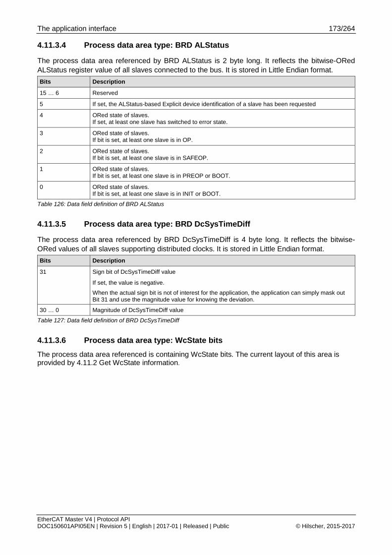
The application interface 173/264
EtherCAT Master V4 | Protocol API DOC150601API05EN | Revision 5 | English | 2017-01 | Released | Public © Hilscher, 2015-2017
4.11.3.4 Process data area type: BRD ALStatus
The process data area referenced by BRD ALStatus is 2 byte long. It reflects the bitwise-ORed ALStatus register value of all slaves connected to the bus. It is stored in Little Endian format. Bits Description
15 … 6 Reserved
5 If set, the ALStatus-based Explicit device identification of a slave has been requested
4 ORed state of slaves. If set, at least one slave has switched to error state.
3 ORed state of slaves. If bit is set, at least one slave is in OP.
2 ORed state of slaves. If bit is set, at least one slave is in SAFEOP.
1 ORed state of slaves. If bit is set, at least one slave is in PREOP or BOOT.
0 ORed state of slaves. If bit is set, at least one slave is in INIT or BOOT.
Table 126: Data field definition of BRD ALStatus
4.11.3.5 Process data area type: BRD DcSysTimeDiff
The process data area referenced by BRD DcSysTimeDiff is 4 byte long. It reflects the bitwise-ORed values of all slaves supporting distributed clocks. It is stored in Little Endian format. Bits Description
31 Sign bit of DcSysTimeDiff value
If set, the value is negative.
When the actual sign bit is not of interest for the application, the application can simply mask out Bit 31 and use the magnitude value for knowing the deviation.
30 … 0 Magnitude of DcSysTimeDiff value
Table 127: Data field definition of BRD DcSysTimeDiff
4.11.3.6 Process data area type: WcState bits
The process data area referenced is containing WcState bits. The current layout of this area is provided by 4.11.2 Get WcState information.

The application interface 174/264
EtherCAT Master V4 | Protocol API DOC150601API05EN | Revision 5 | English | 2017-01 | Released | Public © Hilscher, 2015-2017
4.11.3.7 Process data area type: ExtSync status
The ExtSync Status process data is available since V4.4. It contains data about the current ExtSync status.
Structure Reference typedef struct ECM_EXT_SYNC_DIAG_CYCLIC_DATA_Ttag { uint32_t ulExtSyncInfoFlags; uint16_t usExtSyncStationAddress; uint16_t usControlledStationAddress; uint64_t ullDcToExtTimeOffsetNs; uint32_t ulDcExtErrorDiffNsSignMag; uint32_t ulExtSyncUpdateCount; } ECM_EXT_SYNC_DIAG_CYCLIC_DATA_T;
Structure Description
Element Meaning
ulExtSyncInfoFlags Status flags of ExtSync logic
usExtSyncStationAddress
Fixed station address of slave providing ExtSync data via PDO 0x10F4.
usControlledStationAddress
Fixed station address of DC reference clock
ullDcToExtTimeOffsetNs
Time difference between this network and the other network providing the ExtSync base time.
Relationship of timestamps: DcToExtTimeOffsetNs = ExternalTimestampNs - InternalTimestampNs
ulDcExtErrorDiffNsSignMag
Sign magnitude field to show the actual deviation between external synchronization reference time and own DcSysTime
ulExtSyncUpdateCount Counter incrementing every time when ExtSync data is processed Table 128: ExtSync Status data structure

The application interface 175/264
EtherCAT Master V4 | Protocol API DOC150601API05EN | Revision 5 | English | 2017-01 | Released | Public © Hilscher, 2015-2017
Definition of ulExtSyncInfoFlags
Bits Name (Bit mask) Description
31 MSK_ECM_CYC_EXT_SYNC_INFO_FLAGS_EXT_DEVICE_CONFIGURED (0x80000000)
Ext Sync device has been configured
30 MSK_ECM_CYC_EXT_SYNC_INFO_FLAGS_EXT_DEVICE_ACTIVE (0x40000000)
The master is actively using External synchronization on device
29 MSK_ECM_CYC_EXT_SYNC_INFO_FLAGS_DC_TO_EXT_OFFSET_VALID (0x20000000)
ullDcToExtTimeOffsetNs is valid
28 … 24 reserved Reserved
23 … 16 Used internally Used internally
15 MSK_ECM_CYC_EXT_SYNC_INFO_FLAGS_EXT_DEVICE_CONNECTED_AS_SLAVE (0x00008000)
Ext Sync Device is connected as slave
14 … 6 Reserved Reserved for future use
5 MSK_ECM_CYC_EXT_SYNC_INFO_FLAGS_SYNC_MODE_MASTER (0x00000020)
The master is providing ExtSync to other network
4 MSK_ECM_CYC_EXT_SYNC_INFO_FLAGS_EXT_DEVICE_NOT_CONNECTED (0x00000010)
ExtSync device is not connected when this bit is set
3 Reserved Reserved
2 MSK_ECM_CYC_EXT_SYNC_INFO_FLAGS_IS_64BIT (0x00000004)
ExtSync timestamp size
If not set, the timestamp has 32 bit. If set, the timestamp has 64 bit.
1 Reserved Reserved
0 MSK_ECM_CYC_EXT_SYNC_INFO_FLAGS_SYNC_MODE_SLAVE (0x00000001)
The master is using ExtSync reference provided by other network
Table 129: Parameter ulExtSyncInfoFlags
Definition of ulDcExtErrorDiffNsSignMag
Bits Description
31 Sign bit of value
If set to 1, the magnitude specifies a negative value.
30 … 0 Actual magnitude of the difference in ns (unsigned int)
Table 130: Parameter ulDcExtErrorDiffNsSignMag
When the actual sign bit is not of interest for the application, the application can simply mask out Bit 31 and use the magnitude value for knowing the deviation.

The application interface 176/264
EtherCAT Master V4 | Protocol API DOC150601API05EN | Revision 5 | English | 2017-01 | Released | Public © Hilscher, 2015-2017
4.11.3.8 Get cyclic command mapping packet
Packet structure reference typedef struct ECM_IF_GET_CYCLIC_CMD_MAPPING_REQ_DATA_Ttag { uint32_t ulEntriesStartOffset; } ECM_IF_GET_CYCLIC_CMD_MAPPING_REQ_DATA_T; typedef struct ECM_IF_GET_CYCLIC_CMD_MAPPING_REQ_Ttag { TLR_PACKET_HEADER_T tHead; ECM_IF_GET_CYCLIC_CMD_MAPPING_REQ_DATA_T tData; } ECM_IF_GET_CYCLIC_CMD_MAPPING_REQ_T;
Packet description
Structure ECM_IF_GET_CYCLIC_CMD_MAPPING_REQ_T Type: Request
Variable Type Value / range Description tHead - Structure TLR_PACKET_HEADER_T ulDest UINT32 Destination queue-handle ulSrc UINT32 Source queue-handle ulDestId UINT32 Destination End Point Identifier, specifying the final receiver of the
packet within the Destination Process. Set to 0 for the Initialization Packet
ulSrcId UINT32 Source End Point Identifier, specifying the origin of the packet inside the Source Process
ulLen UINT32 4 Packet Data Length in bytes ulId UINT32 0 ... 232-1 Packet Identification as unique number generated by the Source
Process of the Packet ulSta UINT32 See section Status/Error codes overview ulCmd UINT32 0x9E24 ECM_IF_CMD_GET_CYCLIC_CMD_MAPPING_REQ - Command
ulExt UINT32 0 Extension not in use, set to zero for compatibility reasons ulRout UINT32 X Routing, do not touch
tData – Structure ECM_IF_GET_CYCLIC_CMD_MAPPING_REQ_DATA_T ulEntriesStartOffset
UINT32 Start offset at which the response data has to start Needed when ulTotalEntries in confirmation is larger than the actual packet length First message is always containing 0 here.
Table 131: ECM_IF_CMD_GET_CYCLIC_CMD_MAPPING_REQ – Get cyclic command mapping request

The application interface 177/264
EtherCAT Master V4 | Protocol API DOC150601API05EN | Revision 5 | English | 2017-01 | Released | Public © Hilscher, 2015-2017
Cyclic command mapping entry structure reference typedef struct ECM_IF_CYCLIC_CMD_MAPPING_ENTRY_Ttag { uint16_t usTransmitType; uint16_t usReceiveType; uint16_t usTxImageStartByteOffset; uint16_t usRxImageStartByteOffset; uint16_t usImageByteLength; uint16_t usWkcCompareReceiveByteOffset; } ECM_IF_CYCLIC_CMD_MAPPING_ENTRY_T; enum ECM_IF_CYCLIC_CMD_DATATYPE_Etag { VAL_ECM_IF_CYCLIC_CMD_DATATYPE_UNUSED = 0, VAL_ECM_IF_CYCLIC_CMD_DATATYPE_PROCESS_DATA = 1, VAL_ECM_IF_CYCLIC_CMD_DATATYPE_DC_SYSTIME = 2, VAL_ECM_IF_CYCLIC_CMD_DATATYPE_BRD_ALSTATUS = 3, VAL_ECM_IF_CYCLIC_CMD_DATATYPE_BRD_DC_SYSTIME_DIFF = 4 };
Cyclic command mapping entry structure description
Structure ECM_IF_CYCLIC_CMD_MAPPING_ENTRY_T
Variable name Type Meaning
usTransmitType UINT16 Specifies what kind of data is contained in transmit process data image. See Table 125: Possible values of usTransmitType and usReceiveType
usReceiveType UINT16 Specifies what kind of data is contained in receive process data image
See Table 125: Possible values of usTransmitType and usReceiveType
usTxImageStartByteOffset
UINT16 Byte offset in transmit process data image
Valid if usTransmitType is not equal 0
usRxImageStartByteOffset
UINT16 Byte offset in receive process data image
Valid if usTransmitType is not equal 0
usImageByteLength UINT16 Length of process data
usWkcCompareReceiveByteOffset
UINT16 Placement of received Working Counter (WKC) in receive process data image if not set to 0xFFFF
Table 132: Structure ECM_IF_CYCLIC_CMD_MAPPING_ENTRY_T
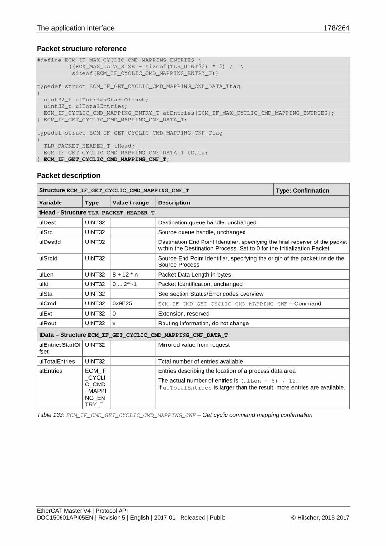
The application interface 178/264
EtherCAT Master V4 | Protocol API DOC150601API05EN | Revision 5 | English | 2017-01 | Released | Public © Hilscher, 2015-2017
Packet structure reference #define ECM_IF_MAX_CYCLIC_CMD_MAPPING_ENTRIES \ ((RCX_MAX_DATA_SIZE - sizeof(TLR_UINT32) * 2) / \ sizeof(ECM_IF_CYCLIC_CMD_MAPPING_ENTRY_T)) typedef struct ECM_IF_GET_CYCLIC_CMD_MAPPING_CNF_DATA_Ttag { uint32_t ulEntriesStartOffset; uint32_t ulTotalEntries; ECM_IF_CYCLIC_CMD_MAPPING_ENTRY_T atEntries[ECM_IF_MAX_CYCLIC_CMD_MAPPING_ENTRIES]; } ECM_IF_GET_CYCLIC_CMD_MAPPING_CNF_DATA_T; typedef struct ECM_IF_GET_CYCLIC_CMD_MAPPING_CNF_Ttag { TLR_PACKET_HEADER_T tHead; ECM_IF_GET_CYCLIC_CMD_MAPPING_CNF_DATA_T tData; } ECM_IF_GET_CYCLIC_CMD_MAPPING_CNF_T;
Packet description
Structure ECM_IF_GET_CYCLIC_CMD_MAPPING_CNF_T Type: Confirmation
Variable Type Value / range Description tHead - Structure TLR_PACKET_HEADER_T ulDest UINT32 Destination queue handle, unchanged ulSrc UINT32 Source queue handle, unchanged ulDestId UINT32 Destination End Point Identifier, specifying the final receiver of the packet
within the Destination Process. Set to 0 for the Initialization Packet
ulSrcId UINT32 Source End Point Identifier, specifying the origin of the packet inside the Source Process
ulLen UINT32 8 + 12 * n Packet Data Length in bytes ulId UINT32 0 ... 232-1 Packet Identification, unchanged ulSta UINT32 See section Status/Error codes overview ulCmd UINT32 0x9E25 ECM_IF_CMD_GET_CYCLIC_CMD_MAPPING_CNF – Command
ulExt UINT32 0 Extension, reserved ulRout UINT32 x Routing information, do not change
tData – Structure ECM_IF_GET_CYCLIC_CMD_MAPPING_CNF_DATA_T ulEntriesStartOffset
UINT32 Mirrored value from request
ulTotalEntries UINT32 Total number of entries available atEntries ECM_IF
_CYCLIC_CMD_MAPPING_ENTRY_T
Entries describing the location of a process data area The actual number of entries is (ulLen – 8) / 12. If ulTotalEntries is larger than the result, more entries are available.
Table 133: ECM_IF_CMD_GET_CYCLIC_CMD_MAPPING_CNF – Get cyclic command mapping confirmation
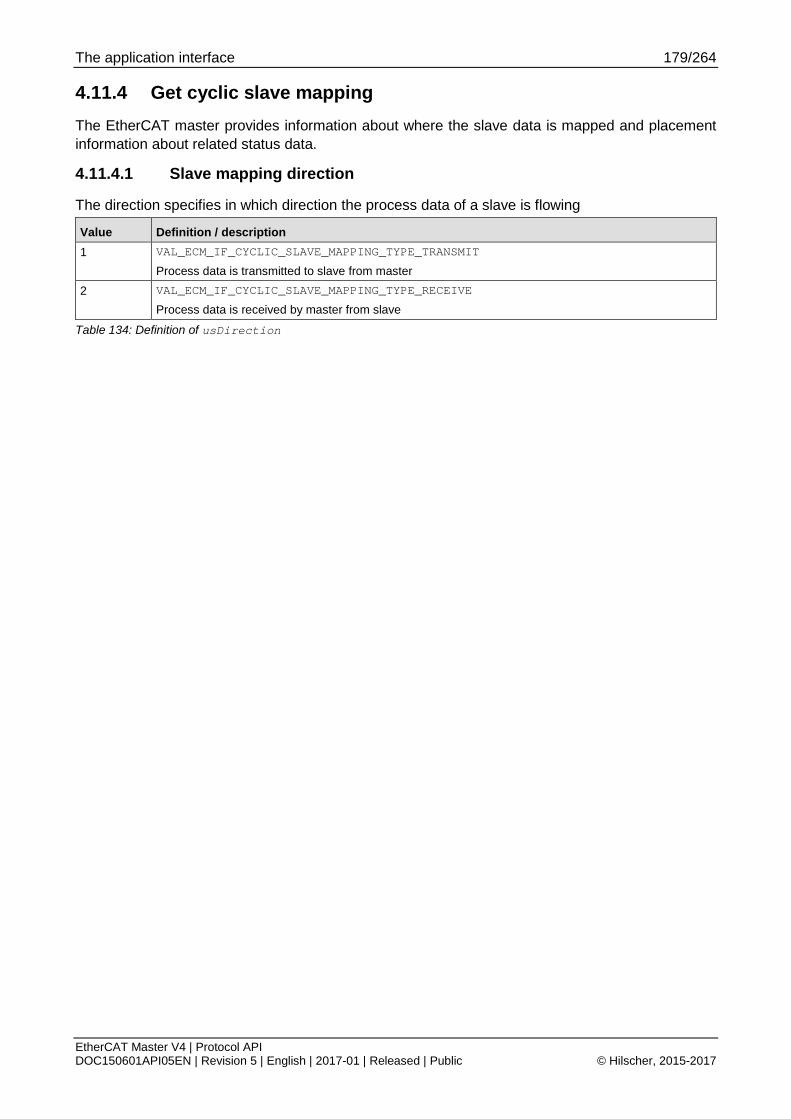
The application interface 179/264
EtherCAT Master V4 | Protocol API DOC150601API05EN | Revision 5 | English | 2017-01 | Released | Public © Hilscher, 2015-2017
4.11.4 Get cyclic slave mapping The EtherCAT master provides information about where the slave data is mapped and placement information about related status data.
4.11.4.1 Slave mapping direction
The direction specifies in which direction the process data of a slave is flowing
Value Definition / description 1 VAL_ECM_IF_CYCLIC_SLAVE_MAPPING_TYPE_TRANSMIT
Process data is transmitted to slave from master 2 VAL_ECM_IF_CYCLIC_SLAVE_MAPPING_TYPE_RECEIVE
Process data is received by master from slave
Table 134: Definition of usDirection

The application interface 180/264
EtherCAT Master V4 | Protocol API DOC150601API05EN | Revision 5 | English | 2017-01 | Released | Public © Hilscher, 2015-2017
4.11.4.2 Get cyclic slave mapping packet
Packet structure reference typedef struct ECM_IF_GET_CYCLIC_SLAVE_MAPPING_REQ_DATA_Ttag { uint32_t ulEntriesStartOffset; } ECM_IF_GET_CYCLIC_SLAVE_MAPPING_REQ_DATA_T; typedef struct ECM_IF_GET_CYCLIC_SLAVE_MAPPING_REQ_Ttag { TLR_PACKET_HEADER_T tHead; ECM_IF_GET_CYCLIC_SLAVE_MAPPING_REQ_DATA_T tData; } ECM_IF_GET_CYCLIC_SLAVE_MAPPING_REQ_T;
Packet description
Structure ECM_IF_GET_CYCLIC_SLAVE_MAPPING_REQ_T Type: Request
Variable Type Value / range Description tHead - Structure TLR_PACKET_HEADER_T ulDest UINT32 Destination queue-handle ulSrc UINT32 Source queue-handle ulDestId UINT32 Destination End Point Identifier, specifying the final receiver of the
packet within the Destination Process. Set to 0 for the Initialization Packet
ulSrcId UINT32 Source End Point Identifier, specifying the origin of the packet inside the Source Process
ulLen UINT32 4 Packet Data Length in bytes ulId UINT32 0 ... 232-1 Packet Identification as unique number generated by the Source
Process of the Packet ulSta UINT32 See section Status/Error codes overview ulCmd UINT32 0x9E26 ECM_IF_CMD_GET_CYCLIC_SLAVE_MAPPING_REQ - Command
ulExt UINT32 0 Extension not in use, set to zero for compatibility reasons ulRout UINT32 X Routing, do not touch
tData – Structure ECM_IF_GET_CYCLIC_SLAVE_MAPPING_REQ_DATA_T ulEntriesStartOffset
UINT32 Start offset at which the response data has to start Needed when ulTotalEntries in confirmation is larger than the actual packet length First message is always containing 0 here.
Table 135: ECM_IF_CMD_GET_CYCLIC_SLAVE_MAPPING_REQ – Get cyclic slave mapping request

The application interface 181/264
EtherCAT Master V4 | Protocol API DOC150601API05EN | Revision 5 | English | 2017-01 | Released | Public © Hilscher, 2015-2017
Cyclic slave mapping entry structure reference typedef struct ECM_IF_CYCLIC_SLAVE_MAPPING_ENTRY_Ttag { uint16_t usDirection; uint16_t usStationAddress; uint16_t usWkcCompareReceiveByteOffset; uint32_t ulWcStateBitOffset; uint32_t ulImageStartBitOffset; uint32_t ulImageBitLength; uint32_t ulBitOffsetWithin; uint8_t bSmNo; uint8_t bFmmuNo; uint16_t usReserved; } ECM_IF_CYCLIC_SLAVE_MAPPING_ENTRY_T; enum ECM_IF_CYCLIC_SLAVE_MAPPING_TYPE_Etag { VAL_ECM_IF_CYCLIC_SLAVE_MAPPING_TYPE_TRANSMIT = 1, VAL_ECM_IF_CYCLIC_SLAVE_MAPPING_TYPE_RECEIVE = 2, };
Cyclic slave mapping entry structure description
Structure ECM_IF_CYCLIC_SLAVE_MAPPING_ENTRY_T
Variable name Type Meaning
usDirection UINT16 Specifies what kind of data is contained in transmit process data image. See Table 134: Definition of usDirection
usStationAddress UINT16 Fixed station address of slave that is referenced by the block
usWkcCompareReceiveByteOffset
UINT16 Byte offset in receive process data image References the actual received working counter if not set to 0xFFFF.
ulWcStateBitOffset UINT32 Bit offset in receive process data image References the actual provided WcState bit which is referring to the data if not set to 0xFFFFFFFF.
ulImageStartBitOffset UINT32 Current start bit offset of referenced process data area
ulImageBitLength UINT32 Current bit length of referenced process data area
ulBitOffsetWithin UINT32 Specifies current bit offset within referenced SyncMan, FMMU or memory of ESC controller
If bFmmuNo is set unequal 0xFF, it references to the start of the FMMU specified by bFmmuNo.
If bSmNo is set unequal 0xFF, it references to the start of the SM specified by bSmNo.
If bFmmuNo and bSmNo are both set to 0xFF, it references to the physical start address within the slave in bits. (register byte address * 8)
bSmNo UINT8 References SyncManager of ESC controller if not set to 0xFF
bFmmuNo UINT8 References FMMU of ESC controller if not set to 0xFF
usReserved UINT16 Reserved for future use
Table 136: Structure ECM_IF_CYCLIC_SLAVE_MAPPING_ENTRY_T

The application interface 182/264
EtherCAT Master V4 | Protocol API DOC150601API05EN | Revision 5 | English | 2017-01 | Released | Public © Hilscher, 2015-2017
Packet structure reference #define ECM_IF_MAX_CYCLIC_SLAVE_MAPPING_ENTRIES \ ((RCX_MAX_DATA_SIZE - sizeof(TLR_UINT32) * 2) / \ sizeof(ECM_IF_CYCLIC_SLAVE_MAPPING_ENTRY_T)) typedef struct ECM_IF_GET_CYCLIC_SLAVE_MAPPING_CNF_DATA_Ttag { uint32_t ulEntriesStartOffset; uint32_t ulTotalEntries; ECM_IF_CYCLIC_SLAVE_MAPPING_ENTRY_T atEntries[ECM_IF_MAX_CYCLIC_SLAVE_MAPPING_ENTRIES]; } ECM_IF_GET_CYCLIC_SLAVE_MAPPING_CNF_DATA_T; typedef struct ECM_IF_GET_CYCLIC_SLAVE_MAPPING_CNF_Ttag { TLR_PACKET_HEADER_T tHead; ECM_IF_GET_CYCLIC_SLAVE_MAPPING_CNF_DATA_T tData; } ECM_IF_GET_CYCLIC_SLAVE_MAPPING_CNF_T;
Packet description
Structure ECM_IF_GET_CYCLIC_SLAVE_MAPPING_CNF_T Type: Confirmation
Variable Type Value / range Description tHead - Structure TLR_PACKET_HEADER_T ulDest UINT32 Destination queue handle, unchanged ulSrc UINT32 Source queue handle, unchanged ulDestId UINT32 Destination End Point Identifier, specifying the final receiver of the packet
within the Destination Process. Set to 0 for the Initialization Packet
ulSrcId UINT32 Source End Point Identifier, specifying the origin of the packet inside the Source Process
ulLen UINT32 8 + 22 * n Packet Data Length in bytes ulId UINT32 0 ... 232-1 Packet Identification, unchanged ulSta UINT32 See section Status/Error codes overview ulCmd UINT32 0x9E27 ECM_IF_CMD_GET_CYCLIC_SLAVE_MAPPING_CNF – Command
ulExt UINT32 0 Extension, reserved ulRout UINT32 x Routing information, do not change
tData – Structure ECM_IF_GET_CYCLIC_SLAVE_MAPPING_CNF_DATA_T ulEntriesStartOffset
UINT32 Mirrored value from request
ulTotalEntries UINT32 Total number of entries available atEntries ECM_IF
_CYCLIC_SLAVE_MAPPING_ENTRY_T
Entries describing the location of a process data area The actual number of entries is (ulLen – 8) / 22. If ulTotalEntries is larger than the result, more entries are available.
Table 137: ECM_IF_CMD_GET_CYCLIC_SLAVE_MAPPING_CNF – Get cyclic slave mapping confirmation

The application interface 183/264
EtherCAT Master V4 | Protocol API DOC150601API05EN | Revision 5 | English | 2017-01 | Released | Public © Hilscher, 2015-2017
4.12 Retrieval of slave diagnostic information The retrieval of slave diagnostic information uses a generic Hilscher DPM mechanism to provide that information.
4.12.1 Provided lists The slave diagnostic provides the following lists for the application:
the configured slaves
the activated slaves
the slaves with a known fault
4.12.2 Limitations of configured slaves list The configured slaves list as given by 4.12.7.1 Get slave handle service can only communicate up to 388 slaves handles.
In that case, the number of configured slaves can be retrieved by one of the two following cases:
the number of configured slaves within Common Status block
4.12.7.2 Get slave handle bit list service.
With one of those two services being used, all slaves can be accessed via 4.12.7.3 Get slave connection information service.
4.12.3 Limitations of active/faulted slaves list The active slaves list and faulted slaves list as given by 4.12.7.1 Get slave handle service can only communicate up to 388 slaves.
If this is not sufficient, the service 4.12.7.2 Get slave handle bit list service has to be used for retrieving data about all slaves.
4.12.4 Addressing scheme The ulDeviceIndex is based on the configuration order. It is neither based on topology position nor on fixed station address.
The device index addressing scheme is described in more detail in section 4.1.4 Device index.
Most other services deal with the Fixed Station address as addressing scheme. For that, it is necessary to request the data via 4.12.7.3 Get slave connection information service.

The application interface 184/264
EtherCAT Master V4 | Protocol API DOC150601API05EN | Revision 5 | English | 2017-01 | Released | Public © Hilscher, 2015-2017
4.12.5 Usage of slave diagnostic information packets
Figure 40: Flow diagram of slave diagnostic information packets
The following packets are referenced:
RCX_GET_SLAVE_HANDLE_REQ
4.12.7.1 Get slave handle service
RCX_GET_SLAVE_CONN_INFO_REQ
4.12.7.3 Get slave connection information service

The application interface 185/264
EtherCAT Master V4 | Protocol API DOC150601API05EN | Revision 5 | English | 2017-01 | Released | Public © Hilscher, 2015-2017
4.12.6 Structure of per slave diagnostic data The following structure is used for providing the slave diagnostic data in the slave diagnostic information functionality.
Structure Reference typedef struct ETHERCAT_MASTER_DIAG_GET_SLAVE_DIAG_Ttag { uint32_t ulStationAddress; uint32_t ulAutoIncAddress; uint32_t ulCurrentState; uint32_t ulLastError; uint8_t szSlaveName[80]; uint32_t fEmergencyReported; } ETHERCAT_MASTER_DIAG_GET_SLAVE_DIAG_T;
Structure Description
Element Meaning
ulStationAddress Fixed station address of slave
ulAutoIncAddress Auto-Increment address of slave
0x0000 first slave in topology 0xFFFF second slave in topology 0xFFFE third slave in topology
ulCurrentState Current status of slave
ulLastError Last error associated with slave
szSlaveName Name of slave (NUL-terminated if not completely used)
fEmergencyReported TRUE if a CoE emergency has been received by master
Table 138: Slave connection information
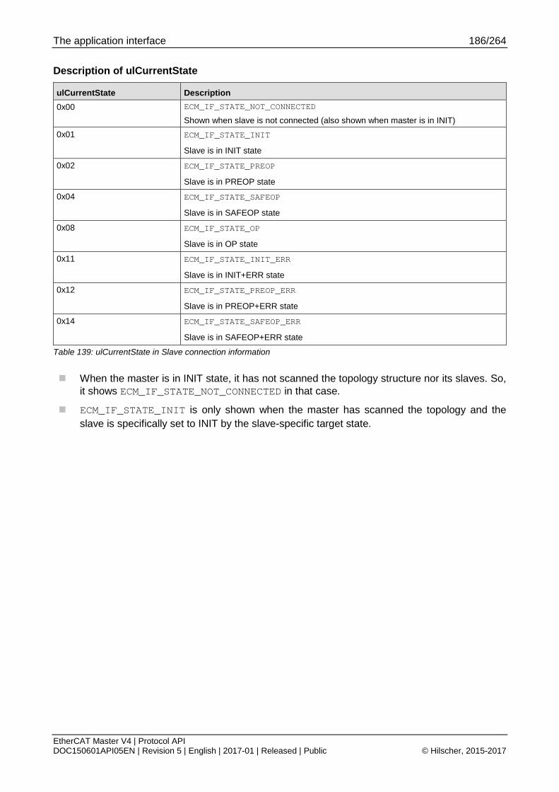
The application interface 186/264
EtherCAT Master V4 | Protocol API DOC150601API05EN | Revision 5 | English | 2017-01 | Released | Public © Hilscher, 2015-2017
Description of ulCurrentState
ulCurrentState Description 0x00 ECM_IF_STATE_NOT_CONNECTED
Shown when slave is not connected (also shown when master is in INIT) 0x01 ECM_IF_STATE_INIT
Slave is in INIT state
0x02 ECM_IF_STATE_PREOP
Slave is in PREOP state
0x04 ECM_IF_STATE_SAFEOP
Slave is in SAFEOP state
0x08 ECM_IF_STATE_OP
Slave is in OP state
0x11 ECM_IF_STATE_INIT_ERR
Slave is in INIT+ERR state
0x12 ECM_IF_STATE_PREOP_ERR
Slave is in PREOP+ERR state
0x14 ECM_IF_STATE_SAFEOP_ERR
Slave is in SAFEOP+ERR state
Table 139: ulCurrentState in Slave connection information
When the master is in INIT state, it has not scanned the topology structure nor its slaves. So, it shows ECM_IF_STATE_NOT_CONNECTED in that case.
ECM_IF_STATE_INIT is only shown when the master has scanned the topology and the slave is specifically set to INIT by the slave-specific target state.

The application interface 187/264
EtherCAT Master V4 | Protocol API DOC150601API05EN | Revision 5 | English | 2017-01 | Released | Public © Hilscher, 2015-2017
4.12.7 Packets
4.12.7.1 Get slave handle service
This service retrieves the list of slaves matching a particular condition (configured, activated or faulted).
Packet structure reference typedef struct RCX_GET_SLAVE_CONN_INFO_REQ_DATA_Ttag { uint32_t ulParam; } RCX_GET_SLAVE_CONN_INFO_REQ_DATA_T; typedef struct RCX_PACKET_GET_SLAVE_HANDLE_REQ_Ttag { TLR_PACKET_HEADER_T tHead; RCX_GET_SLAVE_CONN_INFO_REQ_DATA_T tData; } RCX_PACKET_GET_SLAVE_HANDLE_REQ_T;
Packet description
Structure RCX_PACKET_GET_SLAVE_HANDLE_REQ_T Type: Request
Variable Type Value / range Description tHead - Structure TLR_PACKET_HEADER_T
ulDest UINT32 Destination queue-handle ulSrc UINT32 Source queue-handle ulDestId UINT32 Destination End Point Identifier, specifying the final receiver of the
packet within the Destination Process. Set to 0 for the Initialization Packet
ulSrcId UINT32 Source End Point Identifier, specifying the origin of the packet inside the Source Process
ulLen UINT32 4 Packet Data Length in bytes ulId UINT32 0 ... 232-1 Packet Identification as unique number generated by the Source
Process of the Packet ulSta UINT32 See section Status/Error codes overview ulCmd UINT32 0x2F08 RCX_GET_SLAVE_HANDLE_REQ - Command
ulExt UINT32 Extension, reserved ulRout UINT32 x Routing, do not touch tData - Structure RCX_PACKET_GET_SLAVE_HANDLE_REQ_DATA_T ulParam UINT32 0x00000001 ...
0x00000003 Parameter: 0x00000001 List of Configured Slaves 0x00000002 List of Activated Slaves 0x00000003 List of Faulted Slaves
Table 140: RCX_GET_SLAVE_HANDLE_REQ – Get slave handle request

The application interface 188/264
EtherCAT Master V4 | Protocol API DOC150601API05EN | Revision 5 | English | 2017-01 | Released | Public © Hilscher, 2015-2017
Packet structure reference typedef struct RCX_PACKET_GET_SLAVE_HANDLE_CNF_DATA_Ttag { uint32_t ulParam; uint32_t aulHandle[]; } RCX_PACKET_GET_SLAVE_HANDLE_CNF_DATA_T; typedef struct RCX_PACKET_GET_SLAVE_HANDLE_CNF_Ttag { TLR_PACKET_HEADER_T tHead; RCX_PACKET_GET_SLAVE_HANDLE_CNF_DATA_T tData; } RCX_PACKET_GET_SLAVE_HANDLE_CNF_T;
Packet description
Structure RCX_PACKET_GET_SLAVE_HANDLE_CNF_T Type: Confirmation
Variable Type Value / range Description tHead - Structure TLR_PACKET_HEADER_T ulDest UINT32 Destination queue handle, unchanged ulSrc UINT32 Source queue handle, unchanged ulDestId UINT32 Destination End Point Identifier, specifying the final receiver of the
packet within the Destination Process. Set to 0 for the Initialization Packet
ulSrcId UINT32 Source End Point Identifier, specifying the origin of the packet inside the Source Process
ulLen UINT32 8 + amount of read data
Packet Data Length in bytes
ulId UINT32 0 ... 232-1 Packet Identification, unchanged ulSta UINT32 See section Status/Error codes overview ulCmd UINT32 0x2F09 RCX_GET_SLAVE_HANDLE_CNF - Command
ulExt UINT32 Extension, reserved ulRout UINT32 x Routing information, do not change tData - Structure RCX_PACKET_GET_SLAVE_HANDLE_CNF_DATA_T
ulParam UINT32 0x00000001 ... 0x00000003
Parameter: 0x00000001 List of Configured Slaves 0x00000002 List of Activated Slaves 0x00000003 List of Faulted Slaves
aulHandle[n] UINT32 List of slave handles referred by the specified list n = (ulLen – 8) / 4
Table 141: RCX_GET_SLAVE_HANDLE_CNF – Confirmation of get slave handle request

The application interface 189/264
EtherCAT Master V4 | Protocol API DOC150601API05EN | Revision 5 | English | 2017-01 | Released | Public © Hilscher, 2015-2017
4.12.7.2 Get slave handle bit list service
This service retrieves the bit list of slaves matching a particular condition (configured, activated or faulted). Each set bit translates into a slave handle. The first bit in a confirmation is referring to ulStartHandle. In contrast to 4.12.7.1 Get slave handle service, this request does not have the 388 slaves limit and can address larger configurations.
Packet structure reference typedef struct ECM_IF_GET_SLAVE_HANDLE_BIT_LIST_REQ_DATA_Ttag { uint32_t ulListType; uint32_t ulStartHandle; } ECM_IF_GET_SLAVE_HANDLE_BIT_LIST_REQ_DATA_T; typedef struct ECM_IF_GET_SLAVE_HANDLE_BIT_LIST_REQ_Ttag { TLR_PACKET_HEADER_T tHead; ECM_IF_GET_SLAVE_HANDLE_BIT_LIST_REQ_DATA_T tData; } ECM_IF_GET_SLAVE_HANDLE_BIT_LIST_REQ_T;
Packet description
Structure ECM_IF_GET_SLAVE_HANDLE_BIT_LIST_REQ_T Type: Request
Variable Type Value / range Description tHead - Structure TLR_PACKET_HEADER_T ulDest UINT32 Destination queue-handle ulSrc UINT32 Source queue-handle ulDestId UINT32 Destination End Point Identifier, specifying the final receiver of the
packet within the Destination Process. Set to 0 for the Initialization Packet
ulSrcId UINT32 Source End Point Identifier, specifying the origin of the packet inside the Source Process
ulLen UINT32 8 Packet Data Length in bytes ulId UINT32 0 ... 232-1 Packet Identification as unique number generated by the Source
Process of the Packet ulSta UINT32 See section Status/Error codes overview ulCmd UINT32 0x9E68 ECM_IF_CMD_GET_SLAVE_HANDLE_BIT_LIST_REQ - Command
ulExt UINT32 Extension, reserved ulRout UINT32 x Routing, do not touch tData - Structure ECM_IF_GET_SLAVE_HANDLE_BIT_LIST_REQ_DATA_T ulListType UINT32 0x00000001 ...
0x00000003 Parameter: 0x00000001 List of Configured Slaves 0x00000002 List of Activated Slaves 0x00000003 List of Faulted Slaves
ulStartHandle UINT32 Actual handle the first bit will refer to
Table 142: ECM_IF_CMD_GET_SLAVE_HANDLE_BIT_LIST_REQ – Get slave handle bit list request

The application interface 190/264
EtherCAT Master V4 | Protocol API DOC150601API05EN | Revision 5 | English | 2017-01 | Released | Public © Hilscher, 2015-2017
Packet structure reference typedef struct ECM_IF_GET_SLAVE_HANDLE_BIT_LIST_CNF_DATA_Ttag { uint32_t ulListType; uint32_t ulStartHandle; uint32_t ulNumHandleBits; uint8_t abBitMap[]; } ECM_IF_GET_SLAVE_HANDLE_BIT_LIST_CNF_DATA_T; typedef struct ECM_IF_GET_SLAVE_HANDLE_BIT_LIST_CNF_Ttag { TLR_PACKET_HEADER_T tHead; ECM_IF_GET_SLAVE_HANDLE_BIT_LIST_CNF_DATA_T tData; } ECM_IF_GET_SLAVE_HANDLE_BIT_LIST_CNF_T;
Packet description
Structure ECM_IF_GET_SLAVE_HANDLE_BIT_LIST_CNF_T Type: Confirmation
Variable Type Value / range Description tHead - Structure TLR_PACKET_HEADER_T ulDest UINT32 Destination queue handle, unchanged ulSrc UINT32 Source queue handle, unchanged ulDestId UINT32 Destination End Point Identifier, specifying the final receiver of the
packet within the Destination Process. Set to 0 for the Initialization Packet
ulSrcId UINT32 Source End Point Identifier, specifying the origin of the packet inside the Source Process
ulLen UINT32 12 + n Packet Data Length in bytes ulId UINT32 0 ... 232-1 Packet Identification, unchanged ulSta UINT32 See section Status/Error codes overview ulCmd UINT32 0x9E69 ECM_IF_CMD_GET_SLAVE_HANDLE_BIT_LIST_CNF - Command
ulExt UINT32 Extension, reserved ulRout UINT32 x Routing information, do not change tData - Structure ECM_IF_GET_SLAVE_HANDLE_BIT_LIST_CNF_DATA_T
ulListType UINT32 0x00000001 ... 0x00000003
Parameter: 0x00000001 List of Configured Slaves 0x00000002 List of Activated Slaves 0x00000003 List of Faulted Slaves
ulStartHandle UINT32 Actual handle the first bit will refer to ulNumHandleBits UINT32 Actual number of bits used in abBitmap abBitmap[n] UINT8 Bit List of slave handles referred by the specified list
n = (ulLen – 12) referring to n *8 bits
Table 143: ECM_IF_CMD_GET_SLAVE_HANDLE_BIT_LIST_CNF – Confirmation of get save handle request

The application interface 191/264
EtherCAT Master V4 | Protocol API DOC150601API05EN | Revision 5 | English | 2017-01 | Released | Public © Hilscher, 2015-2017
4.12.7.3 Get slave connection information service
Packet structure reference typedef struct RCX_PACKET_GET_SLAVE_CONN_INFO_REQ_DATA_Ttag { uint32_t ulHandle; } RCX_PACKET_GET_SLAVE_CONN_INFO_REQ_DATA_T; typedef struct RCX_PACKET_GET_SLAVE_CONN_INFO_REQ_Ttag { TLR_PACKET_HEADER_T tHead; RCX_PACKET_GET_SLAVE_CONN_INFO_REQ_DATA_T tData; } RCX_PACKET_GET_SLAVE_CONN_INFO_REQ_T;
Packet description
Structure RCX_PACKET_GET_SLAVE_CONN_INFO_REQ_T Type: Request
Variable Type Value / range Description tHead - Structure TLR_PACKET_HEADER_T ulDest UINT32 Destination queue-handle ulSrc UINT32 Source queue-handle ulDestId UINT32 Destination End Point Identifier, specifying the final receiver of the
packet within the Destination Process. Set to 0 for the Initialization Packet
ulSrcId UINT32 Source End Point Identifier, specifying the origin of the packet inside the Source Process
ulLen UINT32 4 Packet Data Length in bytes ulId UINT32 0 ... 232-1 Packet Identification as unique number generated by the Source
Process of the Packet ulSta UINT32 See section Status/Error codes overview ulCmd UINT32 0x2F0A RCX_GET_SLAVE_CONN_INFO_REQ - Command
ulExt UINT32 Extension, reserved ulRout UINT32 x Routing, do not touch tData - Structure RCX_PACKET_GET_SLAVE_CONN_INFO_REQ_DATA_T
ulHandle UINT32 For addressing scheme see section 4.1.4 Device index.
Table 144: RCX_GET_SLAVE_CONN_INFO_REQ – Get slave connection information request

The application interface 192/264
EtherCAT Master V4 | Protocol API DOC150601API05EN | Revision 5 | English | 2017-01 | Released | Public © Hilscher, 2015-2017
Packet structure reference
Note: Field tSlaveDiagData is only shown for reference the actual packet definition does not have this field. It must be addressed by ((&ptPck->tData) + 1).
typedef struct RCX_PACKET_GET_SLAVE_CONN_INFO_CNF_DATA_Ttag { uint32_t ulHandle; uint32_t ulStructId; /* appended data */ } RCX_PACKET_GET_SLAVE_CONN_INFO_CNF_DATA_T; typedef struct RCX_PACKET_GET_SLAVE_CONN_INFO_CNF_Ttag { TLR_PACKET_HEADER_T tHead; RCX_PACKET_GET_SLAVE_CONN_INFO_CNF_DATA_T tData; ETHERCAT_MASTER_DIAG_GET_SLAVE_DIAG_T tSlaveDiagData; } RCX_PACKET_GET_SLAVE_CONN_INFO_CNF_T;
Packet description
Structure RCX_PACKET_GET_SLAVE_CONN_INFO_CNF_T Type: Confirmation
Variable Type Value / range Description tHead - Structure TLR_PACKET_HEADER_T
ulDest UINT32 Destination queue handle, unchanged ulSrc UINT32 Source queue handle, unchanged ulDestId UINT32 Destination End Point Identifier, specifying the final receiver of the
packet within the Destination Process. Set to 0 for the Initialization Packet
ulSrcId UINT32 Source End Point Identifier, specifying the origin of the packet inside the Source Process
ulLen UINT32 108 Packet Data Length in bytes ulId UINT32 0 ... 232-1 Packet Identification, unchanged ulSta UINT32 See section Status/Error codes overview ulCmd UINT32 0x2F0B RCX_GET_SLAVE_CONN_INFO_CNF - Command
ulExt UINT32 Extension, reserved ulRout UINT32 x Routing information, do not change tData - Structure RCX_GET_SLAVE_CONN_INFO_CNF_DATA_T
ulHandle UINT32 Value from request ulStructId UINT32 5938 structure id used by master for slave diagnostic information
tSlaveDiagData - Structure ETHERCAT_MASTER_DIAG_GET_SLAVE_DIAG_T Structure described in chapter 4.12.6 Structure of per slave diagnostic data
Table 145: RCX_GET_SLAVE_CONN_INFO_CNF – Confirmation of get slave connection information request

The application interface 193/264
EtherCAT Master V4 | Protocol API DOC150601API05EN | Revision 5 | English | 2017-01 | Released | Public © Hilscher, 2015-2017
4.12.7.4 Read CoE emergency messages
This service allows reading the buffered CoE emergency messages from the slaves.
Packet structure reference typedef struct ETHERCAT_MASTER_PACKET_SLAVE_EMERGENCY_INFO_REQ_DATA_Ttag { uint32_t ulSlaveHandle; uint32_t fDeleteEmergency; } ETHERCAT_MASTER_PACKET_SLAVE_EMERGENCY_INFO_REQ_DATA_T; typedef struct ETHERCAT_MASTER_PACKET_SLAVE_EMERGENCY_INFO_REQ_Ttag { TLR_PACKET_HEADER_T tHead; ETHERCAT_MASTER_PACKET_SLAVE_EMERGENCY_INFO_REQ_DATA_T tData; } ETHERCAT_MASTER_PACKET_SLAVE_EMERGENCY_INFO_REQ_T;
Packet description
Structure ETHERCAT_MASTER_PACKET_SLAVE_EMERGENCY_INFO_REQ_T Type: Request
Variable Type Value / range Description tHead - Structure TLR_PACKET_HEADER_T ulDest UINT32 Destination queue-handle ulSrc UINT32 Source queue-handle ulDestId UINT32 Destination End Point Identifier, specifying the final receiver of the
packet within the Destination Process. Set to 0 for the Initialization Packet
ulSrcId UINT32 Source End Point Identifier, specifying the origin of the packet inside the Source Process
ulLen UINT32 8 Packet Data Length in bytes ulId UINT32 0 ... 232-1 Packet Identification as unique number generated by the Source
Process of the Packet ulSta UINT32 See section Status/Error codes overview ulCmd UINT32 0x65001C ETHERCAT_MASTER_CMD_READ_EMERGENCY_REQ - Command
ulExt UINT32 Extension, reserved ulRout UINT32 x Routing, do not touch tData - Structure ETHERCAT_MASTER_PACKET_SLAVE_EMERGENCY_INFO_REQ_DATA_T ulSlaveHandle UINT32 For addressing scheme see section 4.1.4 Device index. fDeleteEmergency UINT32 Flag to decide whether to keep emergencies (0) after read or remove
from buffer (1)
Table 146: ETHERCAT_MASTER_CMD_READ_EMERGENCY_REQ – Get slave CoE emergencies request

The application interface 194/264
EtherCAT Master V4 | Protocol API DOC150601API05EN | Revision 5 | English | 2017-01 | Released | Public © Hilscher, 2015-2017
Packet structure reference #define ETHERCAT_MASTER_COE_NUMBER_OF_EMERGENCY (5) #define ETHERCAT_MASTER_COE_EMERGENCY_DATA_BYTES (5) typedef struct ETHERCAT_MASTER_SLAVE_EMERGENCY_Ttag { uint16_t usErrorCode; uint8_t bErrorRegister; uint8_t abErrorData[ETHERCAT_MASTER_COE_EMERGENCY_DATA_BYTES]; } ETHERCAT_MASTER_SLAVE_EMERGENCY_T; Typedef struct ETHERCAT_MASTER_PACKET_SLAVE_EMERGENCY_INFO_CNF_DATA_Ttag { uint32_t ulSlaveHandle; uint32_t fDeleteEmergency; uint32_t fOverFlowOccured; ETHERCAT_MASTER_SLAVE_EMERGENCY_T atEmergenyBuffer[ETHERCAT_MASTER_COE_NUMBER_OF_EMERGENCY]; } ETHERCAT_MASTER_PACKET_SLAVE_EMERGENCY_INFO_CNF_DATA_T; typedef struct ETHERCAT_MASTER_PACKET_SLAVE_EMERGENCY_INFO_CNF_Ttag { TLR_PACKET_HEADER_T tHead; ETHERCAT_MASTER_PACKET_SLAVE_EMERGENCY_INFO_CNF_DATA_T tData; } ETHERCAT_MASTER_PACKET_SLAVE_EMERGENCY_INFO_CNF_T;
Packet description
Structure ETHERCAT_MASTER_PACKET_SLAVE_EMERGENCY_INFO_CNF_T Type: Confirmation
Variable Type Value / range Description tHead - Structure TLR_PACKET_HEADER_T
ulDest UINT32 Destination queue handle, unchanged ulSrc UINT32 Source queue handle, unchanged ulDestId UINT32 Destination End Point Identifier, specifying the final receiver of the
packet within the Destination Process. Set to 0 for the Initialization Packet
ulSrcId UINT32 Source End Point Identifier, specifying the origin of the packet inside the Source Process
ulLen UINT32 108 Packet Data Length in bytes ulId UINT32 0 ... 232-1 Packet Identification, unchanged ulSta UINT32 See section Status/Error codes overview ulCmd UINT32 0x65001D ETHERCAT_MASTER_CMD_READ_EMERGENCY_CNF - Command
ulExt UINT32 Extension, reserved ulRout UINT32 x Routing information, do not change tData - Structure RETHERCAT_MASTER_PACKET_SLAVE_EMERGENCY_INFO_CNF_DATA_T
ulSlaveHandle UINT32 Value from request fDeleteEmergency
UINT32 Value from request
fOverflowOccured UINT32 An overflow has occurred (i.e. emergencies have been dropped) atEmergenyBuffer[5]
ETHERCAT_MASTER_SLAVE_EMERGENCY_T
Up to 5 emergencies (see Table 148: Structure of ETHERCAT_MASTER_SLAVE_EMERGENCY_T)
Table 147: ETHERCAT_MASTER_CMD_READ_EMERGENCY_CNF – Confirmation of get slave CoE emergencies request

The application interface 195/264
EtherCAT Master V4 | Protocol API DOC150601API05EN | Revision 5 | English | 2017-01 | Released | Public © Hilscher, 2015-2017
Structure ETHERCAT_MASTER_SLAVE_EMERGENCY_T
Variable Type Value / Range Description
usErrorCode UINT16 Error code according to EtherCAT specification
bErrorRegister UINT8 Error register
abErrorData[5] UINT8 Error data
Table 148: Structure of ETHERCAT_MASTER_SLAVE_EMERGENCY_T

The application interface 196/264
EtherCAT Master V4 | Protocol API DOC150601API05EN | Revision 5 | English | 2017-01 | Released | Public © Hilscher, 2015-2017
4.13 Retrieval of topology information The EtherCAT master provides access to the currently known topology structure of the bus.
The service supports fragmentation for retrieving data. The current topology information is latched at start of fragmented transfer.
4.13.1 Get topology information entries The topology information entries appear in topology order in confirmation. The port order of an EtherCAT slave is 0, 3, 1 and 2.
Structure Reference typedef struct ECM_IF_GET_TOPOLGOY_INFO_CNF_DATA_ENTRY_Ttag { uint16_t usThisSlaveAddress; uint16_t ausPortConnectedTo[4]; } ECM_IF_GET_TOPOLOGY_INFO_CNF_DATA_ENTRY_T;
Structure Description
Element Meaning
usThisSlaveAddress Fixed station address of slave
ausPortConnectedTo[0] To which slave is the port 0 connected.
0 = MASTER
1 … n = slave fixed station address
0xFFFF = NOT CONNECTED
ausPortConnectedTo[1] To which slave is the port 0 connected.
0 = MASTER
1 … n = slave fixed station address
0xFFFF = NOT CONNECTED
ausPortConnectedTo[2] To which slave is the port 0 connected.
0 = MASTER
1 … n = slave fixed station address
0xFFFF = NOT CONNECTED
ausPortConnectedTo[3] To which slave is the port 0 connected.
0 = MASTER
1 … n = slave fixed station address
0xFFFF = NOT CONNECTED Table 149: Topology information entry

The application interface 197/264
EtherCAT Master V4 | Protocol API DOC150601API05EN | Revision 5 | English | 2017-01 | Released | Public © Hilscher, 2015-2017
4.13.2 Get topology information packet
Packet structure reference typedef struct ECM_IF_GET_TOPOLOGY_INFO_REQ_Ttag { TLR_PACKET_HEADER_T tHead; } ECM_IF_GET_TOPOLOGY_INFO_REQ_T;
Packet description
Structure ECM_IF_GET_TOPOLOGY_INFO_REQ_T Type: Request
Variable Type Value / range Description tHead - Structure TLR_PACKET_HEADER_T
ulDest UINT32 Destination queue-handle ulSrc UINT32 Source queue-handle ulDestId UINT32 Destination End Point Identifier, specifying the final receiver of the
packet within the Destination Process. Set to 0 for the Initialization Packet
ulSrcId UINT32 Source End Point Identifier, specifying the origin of the packet inside the Source Process
ulLen UINT32 0 Packet Data Length in bytes ulId UINT32 0 ... 232-1 Packet Identification as unique number generated by the Source
Process of the Packet ulSta UINT32 See section Status/Error codes overview ulCmd UINT32 0x9E50 ECM_IF_CMD_GET_TOPOLOGY_INFO_REQ - Command
ulExt UINT32 0 Extension not in use, set to zero for compatibility reasons ulRout UINT32 X Routing, do not touch
Table 150: ECM_IF_CMD_GET_TOPOLOGY_INFO_REQ – Get topology information request
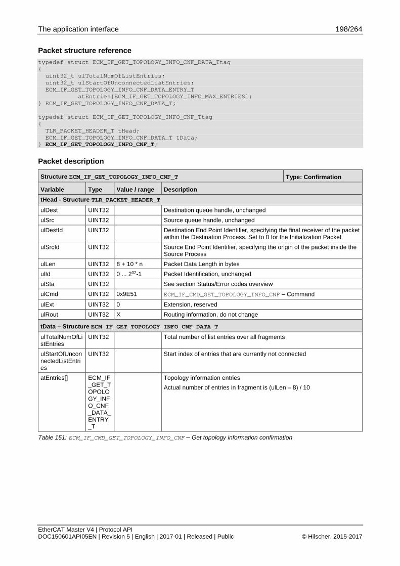
The application interface 198/264
EtherCAT Master V4 | Protocol API DOC150601API05EN | Revision 5 | English | 2017-01 | Released | Public © Hilscher, 2015-2017
Packet structure reference typedef struct ECM_IF_GET_TOPOLOGY_INFO_CNF_DATA_Ttag { uint32_t ulTotalNumOfListEntries; uint32_t ulStartOfUnconnectedListEntries; ECM_IF_GET_TOPOLOGY_INFO_CNF_DATA_ENTRY_T atEntries[ECM_IF_GET_TOPOLOGY_INFO_MAX_ENTRIES]; } ECM_IF_GET_TOPOLOGY_INFO_CNF_DATA_T; typedef struct ECM_IF_GET_TOPOLOGY_INFO_CNF_Ttag { TLR_PACKET_HEADER_T tHead; ECM_IF_GET_TOPOLOGY_INFO_CNF_DATA_T tData; } ECM_IF_GET_TOPOLOGY_INFO_CNF_T;
Packet description
Structure ECM_IF_GET_TOPOLOGY_INFO_CNF_T Type: Confirmation
Variable Type Value / range Description tHead - Structure TLR_PACKET_HEADER_T ulDest UINT32 Destination queue handle, unchanged ulSrc UINT32 Source queue handle, unchanged ulDestId UINT32 Destination End Point Identifier, specifying the final receiver of the packet
within the Destination Process. Set to 0 for the Initialization Packet ulSrcId UINT32 Source End Point Identifier, specifying the origin of the packet inside the
Source Process ulLen UINT32 8 + 10 * n Packet Data Length in bytes ulId UINT32 0 ... 232-1 Packet Identification, unchanged ulSta UINT32 See section Status/Error codes overview ulCmd UINT32 0x9E51 ECM_IF_CMD_GET_TOPOLOGY_INFO_CNF – Command
ulExt UINT32 0 Extension, reserved ulRout UINT32 X Routing information, do not change
tData – Structure ECM_IF_GET_TOPOLOGY_INFO_CNF_DATA_T ulTotalNumOfListEntries
UINT32 Total number of list entries over all fragments
ulStartOfUnconnectedListEntries
UINT32 Start index of entries that are currently not connected
atEntries[] ECM_IF_GET_TOPOLOGY_INFO_CNF_DATA_ENTRY_T
Topology information entries Actual number of entries in fragment is (ulLen – 8) / 10
Table 151: ECM_IF_CMD_GET_TOPOLOGY_INFO_CNF – Get topology information confirmation

The application interface 199/264
EtherCAT Master V4 | Protocol API DOC150601API05EN | Revision 5 | English | 2017-01 | Released | Public © Hilscher, 2015-2017
4.14 ESC/SII access
4.14.1 ESC register access
4.14.1.1 Read ESC registers
This packet provides read access to a specific slave’s ESC registers.
The following addressing schemes are used:
During bus scan, use 4.1.3 Topology position
During normal operation, use 4.1.2 Fixed station address
Packet structure reference typedef struct ECM_IF_READ_REGS_REQ_DATA_Ttag { uint16_t usStationAddress; uint16_t usPhysAddr; uint16_t usPhysLength; } ECM_IF_READ_REGS_REQ_DATA_T; typedef struct ECM_IF_READ_REGS_REQ_Ttag { TLR_PACKET_HEADER_T tHead; ECM_IF_READ_REGS_REQ_DATA_T tData; } ECM_IF_READ_REGS_REQ_T;
Packet description
Structure ECM_IF_READ_REGS_REQ_T Type: Request
Variable Type Value / range Description tHead - Structure TLR_PACKET_HEADER_T ulDest UINT32 Destination queue-handle ulSrc UINT32 Source queue-handle ulDestId UINT32 Destination End Point Identifier, specifying the final receiver of the
packet within the Destination Process. Set to 0 for the Initialization Packet
ulSrcId UINT32 Source End Point Identifier, specifying the origin of the packet inside the Source Process
ulLen UINT32 6 Packet Data Length in bytes ulId UINT32 0 ... 232-1 Packet Identification as unique number generated by the Source
Process of the Packet ulSta UINT32 See section Status/Error codes overview ulCmd UINT32 0x9E70 ECM_IF_CMD_READ_REGS_REQ - Command
ulExt UINT32 0 Extension not in use, set to zero for compatibility reasons ulRout UINT32 x Routing, do not touch
tData – Structure ECM_IF_READ_REGS_REQ_DATA_T
usStationAddress UINT16 Valid address During bus scan, use 4.1.3 Topology position During normal operation, use 4.1.2 Fixed station address
usPhysAddr UINT16 Physical start address in ESC physical memory address space usPhysLength UINT16 Byte Length of physical memory address space to be read
Table 152: ECM_IF_CMD_READ_REGS_REQ – Read ESC registers request

The application interface 200/264
EtherCAT Master V4 | Protocol API DOC150601API05EN | Revision 5 | English | 2017-01 | Released | Public © Hilscher, 2015-2017
Packet structure reference typedef struct ECM_IF_READ_REGS_CNF_DATA_Ttag { uint16_t usStationAddress; uint16_t usPhysAddr; uint16_t usPhysLength; uint8_t abData[1024]; /* actual byte length based on usPhysLength */ } ECM_IF_READ_REGS_CNF_DATA_T; typedef struct ECM_IF_READ_REGS_CNF_Ttag { TLR_PACKET_HEADER_T tHead; ECM_IF_READ_REGS_CNF_DATA_T tData; } ECM_IF_READ_REGS_CNF_T;
Packet description
Structure ECM_IF_READ_REGS_CNF_T Type: Confirmation
Variable Type Value / range Description tHead - Structure TLR_PACKET_HEADER_T ulDest UINT32 Destination queue handle, unchanged ulSrc UINT32 Source queue handle, unchanged ulDestId UINT32 Destination End Point Identifier, specifying the final receiver of the
packet within the Destination Process. Set to 0 for the Initialization Packet
ulSrcId UINT32 Source End Point Identifier, specifying the origin of the packet inside the Source Process
ulLen UINT32 6 + n Packet Data Length in bytes ulId UINT32 0 ... 232-1 Packet Identification, unchanged ulSta UINT32 See section Status/Error codes overview ulCmd UINT32 0x9E71 ECM_IF_CMD_READ_REGS_CNF – Command
ulExt UINT32 0 Extension, reserved ulRout UINT32 x Routing information, do not change
tData – Structure ECM_IF_READ_REGS_CNF_DATA_T usStationAddress
UINT16 Value from request
usPhysAddr UINT16 Physical start address in ESC physical memory address space usPhysLength UINT16 Byte Length of physical memory address space to be read abData[n] UINT8[] Register data having been read
(actual array length equals to usPhysLength)
Table 153: ECM_IF_CMD_READ_REGS_CNF – Read ESC registers confirmation
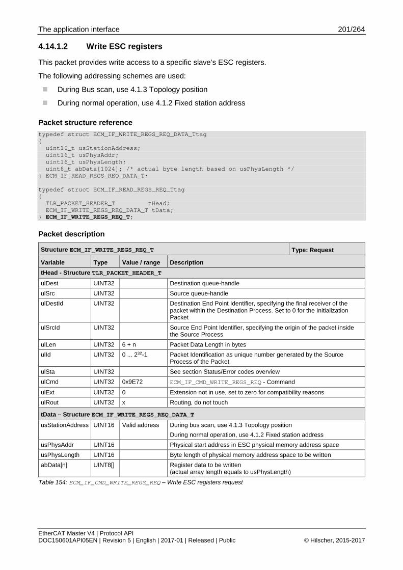
The application interface 201/264
EtherCAT Master V4 | Protocol API DOC150601API05EN | Revision 5 | English | 2017-01 | Released | Public © Hilscher, 2015-2017
4.14.1.2 Write ESC registers
This packet provides write access to a specific slave’s ESC registers.
The following addressing schemes are used:
During Bus scan, use 4.1.3 Topology position
During normal operation, use 4.1.2 Fixed station address
Packet structure reference typedef struct ECM_IF_WRITE_REGS_REQ_DATA_Ttag { uint16_t usStationAddress; uint16_t usPhysAddr; uint16_t usPhysLength; uint8_t abData[1024]; /* actual byte length based on usPhysLength */ } ECM_IF_READ_REGS_REQ_DATA_T; typedef struct ECM_IF_READ_REGS_REQ_Ttag { TLR_PACKET_HEADER_T tHead; ECM_IF_WRITE_REGS_REQ_DATA_T tData; } ECM_IF_WRITE_REGS_REQ_T;
Packet description
Structure ECM_IF_WRITE_REGS_REQ_T Type: Request
Variable Type Value / range Description tHead - Structure TLR_PACKET_HEADER_T
ulDest UINT32 Destination queue-handle ulSrc UINT32 Source queue-handle ulDestId UINT32 Destination End Point Identifier, specifying the final receiver of the
packet within the Destination Process. Set to 0 for the Initialization Packet
ulSrcId UINT32 Source End Point Identifier, specifying the origin of the packet inside the Source Process
ulLen UINT32 6 + n Packet Data Length in bytes ulId UINT32 0 ... 232-1 Packet Identification as unique number generated by the Source
Process of the Packet ulSta UINT32 See section Status/Error codes overview ulCmd UINT32 0x9E72 ECM_IF_CMD_WRITE_REGS_REQ - Command
ulExt UINT32 0 Extension not in use, set to zero for compatibility reasons ulRout UINT32 x Routing, do not touch
tData – Structure ECM_IF_WRITE_REGS_REQ_DATA_T usStationAddress UINT16 Valid address During bus scan, use 4.1.3 Topology position
During normal operation, use 4.1.2 Fixed station address usPhysAddr UINT16 Physical start address in ESC physical memory address space usPhysLength UINT16 Byte length of physical memory address space to be written abData[n] UINT8[] Register data to be written
(actual array length equals to usPhysLength)
Table 154: ECM_IF_CMD_WRITE_REGS_REQ – Write ESC registers request
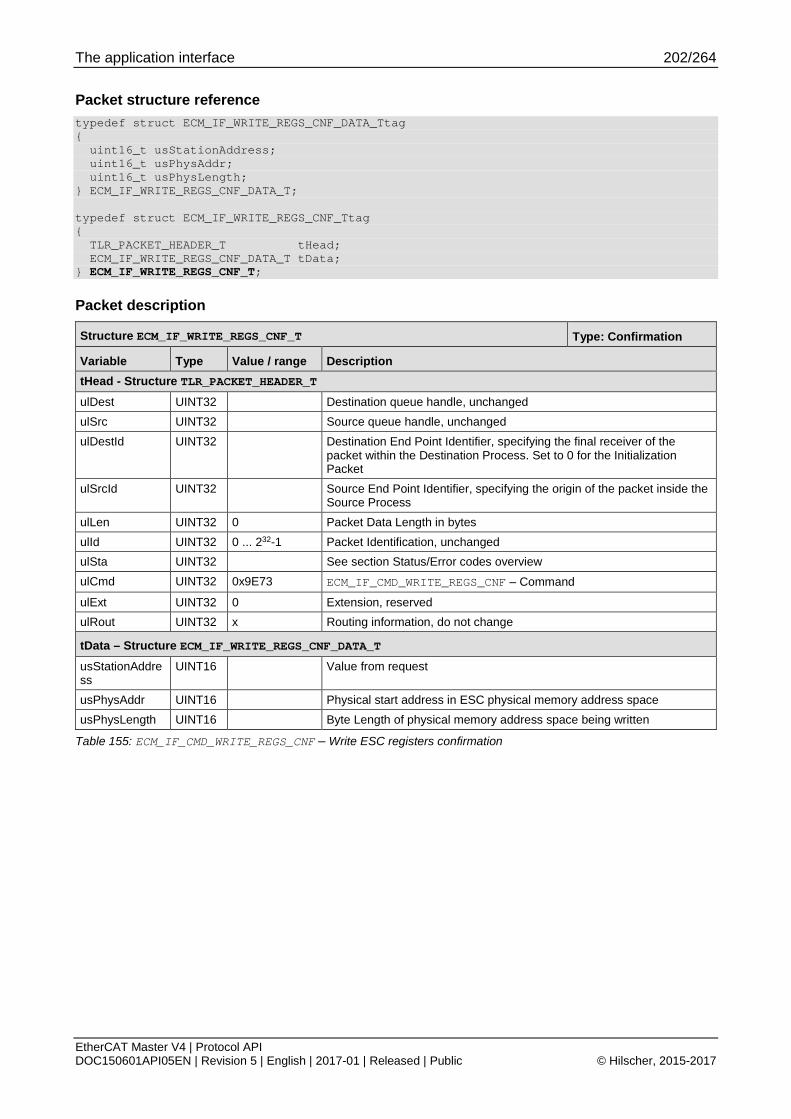
The application interface 202/264
EtherCAT Master V4 | Protocol API DOC150601API05EN | Revision 5 | English | 2017-01 | Released | Public © Hilscher, 2015-2017
Packet structure reference typedef struct ECM_IF_WRITE_REGS_CNF_DATA_Ttag { uint16_t usStationAddress; uint16_t usPhysAddr; uint16_t usPhysLength; } ECM_IF_WRITE_REGS_CNF_DATA_T; typedef struct ECM_IF_WRITE_REGS_CNF_Ttag { TLR_PACKET_HEADER_T tHead; ECM_IF_WRITE_REGS_CNF_DATA_T tData; } ECM_IF_WRITE_REGS_CNF_T;
Packet description
Structure ECM_IF_WRITE_REGS_CNF_T Type: Confirmation
Variable Type Value / range Description tHead - Structure TLR_PACKET_HEADER_T ulDest UINT32 Destination queue handle, unchanged ulSrc UINT32 Source queue handle, unchanged ulDestId UINT32 Destination End Point Identifier, specifying the final receiver of the
packet within the Destination Process. Set to 0 for the Initialization Packet
ulSrcId UINT32 Source End Point Identifier, specifying the origin of the packet inside the Source Process
ulLen UINT32 0 Packet Data Length in bytes ulId UINT32 0 ... 232-1 Packet Identification, unchanged ulSta UINT32 See section Status/Error codes overview ulCmd UINT32 0x9E73 ECM_IF_CMD_WRITE_REGS_CNF – Command
ulExt UINT32 0 Extension, reserved ulRout UINT32 x Routing information, do not change
tData – Structure ECM_IF_WRITE_REGS_CNF_DATA_T usStationAddress
UINT16 Value from request
usPhysAddr UINT16 Physical start address in ESC physical memory address space usPhysLength UINT16 Byte Length of physical memory address space being written
Table 155: ECM_IF_CMD_WRITE_REGS_CNF – Write ESC registers confirmation

The application interface 203/264
EtherCAT Master V4 | Protocol API DOC150601API05EN | Revision 5 | English | 2017-01 | Released | Public © Hilscher, 2015-2017
4.14.2 ESC SII access
4.14.2.1 Read SII/EEPROM
This packet provides read access to a specific slave’s SII/ EEPROM data.
The following addressing schemes are used:
During Bus scan, use 4.1.3 Topology position
During normal operation, use 4.1.2 Fixed station address
Packet structure reference typedef struct ECM_IF_READ_SII_REQ_DATA_Ttag { uint16_t usStationAddress; uint32_t ulSiiWordOffset; uint32_t ulSiiByteLength; } ECM_IF_READ_REGS_REQ_DATA_T; typedef struct ECM_IF_READ_REGS_REQ_Ttag { TLR_PACKET_HEADER_T tHead; ECM_IF_READ_SII_REQ_DATA_T tData; } ECM_IF_READ_SII_REQ_T;
Packet description
Structure ECM_IF_READ_SII_REQ_T Type: Request
Variable Type Value / range Description tHead - Structure TLR_PACKET_HEADER_T ulDest UINT32 Destination queue-handle ulSrc UINT32 Source queue-handle ulDestId UINT32 Destination End Point Identifier, specifying the final receiver of the
packet within the Destination Process. Set to 0 for the Initialization Packet
ulSrcId UINT32 Source End Point Identifier, specifying the origin of the packet inside the Source Process
ulLen UINT32 10 Packet Data Length in bytes ulId UINT32 0 ... 232-1 Packet Identification as unique number generated by the Source
Process of the Packet ulSta UINT32 See section Status/Error codes overview ulCmd UINT32 0x9E80 ECM_IF_CMD_READ_SII_REQ - Command
ulExt UINT32 0 Extension not in use, set to zero for compatibility reasons ulRout UINT32 x Routing, do not touch
tData – Structure ECM_IF_READ_SII_REQ_DATA_T usStationAddress UINT16 During bus scan, use 4.1.3 Topology position
During normal operation, use 4.1.2 Fixed station address ulSiiWordOffset UINT32 SII word offset
0 => first word (at byte offset 0) 1 => second word (at byte offset 2)
ulSiiByteLength UINT32 Length of SII data to be read in bytes Must be a multiple of 2.
Table 156: ECM_IF_CMD_READ_SII_REQ – Read SII/EEPROM request

The application interface 204/264
EtherCAT Master V4 | Protocol API DOC150601API05EN | Revision 5 | English | 2017-01 | Released | Public © Hilscher, 2015-2017
Packet structure reference typedef struct ECM_IF_READ_SII_CNF_DATA_Ttag { uint16_t usStationAddress; uint32_t ulSiiWordOffset; uint32_t ulSiiByteLength; uint8_t abData[1024]; } ECM_IF_READ_SII_CNF_DATA_T typedef struct ECM_IF_READ_SII_CNF_Ttag { TLR_PACKET_HEADER_T tHead; ECM_IF_READ_SII_CNF_DATA_T tData; } ECM_IF_READ_SII_CNF_T;
Packet description
Structure ECM_IF_READ_SII_CNF_T Type: Confirmation
Variable Type Value / range Description tHead - Structure TLR_PACKET_HEADER_T ulDest UINT32 Destination queue handle, unchanged ulSrc UINT32 Source queue handle, unchanged ulDestId UINT32 Destination End Point Identifier, specifying the final receiver of the packet
within the Destination Process. Set to 0 for the Initialization Packet ulSrcId UINT32 Source End Point Identifier, specifying the origin of the packet inside the
Source Process ulLen UINT32 10 + n Packet Data Length in bytes ulId UINT32 0 ... 232-1 Packet Identification, unchanged ulSta UINT32 See section Status/Error codes overview ulCmd UINT32 0x9E81 ECM_IF_CMD_READ_SII_CNF – Command
ulExt UINT32 0 Extension, reserved ulRout UINT32 x Routing information, do not change
tData – Structure ECM_IF_READ_SII_CNF_DATA_T usStationAddress UINT16 Value from request ulSiiWordOffset UINT32 SII word offset
0 => first word (at byte offset 0) 1 => second word (at byte offset 2)
ulSiiByteLength UINT32 Length of SII data to be read in bytes abData[n] UINT8[] Read data from SII/EEPROM
Actual length depends on ulLen
Table 157: ECM_IF_CMD_READ_SII_CNF – Read SII/EEPROM confirmation

The application interface 205/264
EtherCAT Master V4 | Protocol API DOC150601API05EN | Revision 5 | English | 2017-01 | Released | Public © Hilscher, 2015-2017
4.14.2.2 Write SII/EEPROM
This packet provides write access to a specific slave’s SII/ EEPROM data.
The following addressing schemes are used:
During bus scan, use 4.1.3 Topology position
During normal operation, use 4.1.2 Fixed station address
Packet structure reference typedef struct ECM_IF_WRITE_SII_REQ_DATA_Ttag { uint16_t usStationAddress; uint32_t ulSiiWordOffset uint32_t ulReserved; uint8_t abData[1024]; } ECM_IF_WRITE_SII_REQ_DATA_T; typedef struct ECM_IF_WRITE_SII_REQ_Ttag { TLR_PACKET_HEADER_T tHead; ECM_IF_WRITE_SII_REQ_DATA_T tData; } ECM_IF_WRITE_SII_REQ_T;
Packet description
Structure ECM_IF_WRITE_SII_REQ_T Type: Request
Variable Type Value / range Description tHead - Structure TLR_PACKET_HEADER_T
ulDest UINT32 Destination queue-handle ulSrc UINT32 Source queue-handle ulDestId UINT32 Destination End Point Identifier, specifying the final receiver of the
packet within the Destination Process. Set to 0 for the Initialization Packet
ulSrcId UINT32 Source End Point Identifier, specifying the origin of the packet inside the Source Process
ulLen UINT32 10 + n Packet Data Length in bytes ulId UINT32 0 ... 232-1 Packet Identification as unique number generated by the Source
Process of the Packet ulSta UINT32 See section Status/Error codes overview ulCmd UINT32 0x9E82 ECM_IF_CMD_WRITE_SII_REQ - Command
ulExt UINT32 0 Extension not in use, set to zero for compatibility reasons ulRout UINT32 x Routing, do not touch
tData – Structure ECM_IF_WRITE_SII_REQ_DATA_T usStationAddress UINT16 During bus scan, use 4.1.3 Topology position
During normal operation, use 4.1.2 Fixed station address ulSiiWordOffset UINT32 SII word offset
0 => first word (at byte offset 0) 1 => second word (at byte offset 2)
ulReserved UINT32 Set to zero abData[n] UINT8[] Data to be written
Byte length must be a multiple of 2 and is defined as ulLen - 10
Table 158: ECM_IF_CMD_WRITE_SII_REQ – Write SII/EEPROM request

The application interface 206/264
EtherCAT Master V4 | Protocol API DOC150601API05EN | Revision 5 | English | 2017-01 | Released | Public © Hilscher, 2015-2017
Packet structure reference typedef struct ECM_IF_WRITE_SII_CNF_DATA_Ttag { uint16_t usStationAddress; uint32_t ulSiiWordOffset; uint32_t ulWrittenByteLength; } ECM_IF_WRITE_SII_CNF_DATA_T; typedef struct ECM_IF_WRITE_SII_CNF_Ttag { TLR_PACKET_HEADER_T tHead; ECM_IF_WRITE_SII_CNF_DATA_T tData; } ECM_IF_WRITE_SII_CNF_T;
Packet description
Structure ECM_IF_WRITE_SII_CNF_T Type: Confirmation
Variable Type Value / range Description tHead - Structure TLR_PACKET_HEADER_T ulDest UINT32 Destination queue handle, unchanged ulSrc UINT32 Source queue handle, unchanged ulDestId UINT32 Destination End Point Identifier, specifying the final receiver of the
packet within the Destination Process. Set to 0 for the Initialization Packet
ulSrcId UINT32 Source End Point Identifier, specifying the origin of the packet inside the Source Process
ulLen UINT32 0 Packet Data Length in bytes ulId UINT32 0 ... 232-1 Packet Identification, unchanged ulSta UINT32 See section Status/Error codes overview ulCmd UINT32 0x9E83 ECM_IF_CMD_WRITE_SII_CNF – Command
ulExt UINT32 0 Extension, reserved ulRout UINT32 x Routing information, do not change
tData – Structure ECM_IF_WRITE_SII_CNF_DATA_T usStationAddress
UINT16 Value from request
ulSiiWordOffset UINT32 SII word offset 0 => first word (at byte offset 0) 1 => second word (at byte offset 2)
ulWrittenByteLength
UINT32 Actual byte length of SII data to being written in bytes
Table 159: ECM_IF_CMD_WRITE_SII_CNF – Write SII/EEPROM confirmation

The application interface 207/264
EtherCAT Master V4 | Protocol API DOC150601API05EN | Revision 5 | English | 2017-01 | Released | Public © Hilscher, 2015-2017
4.14.3 Legacy ESC SII access (ECM V3.X API) The legacy SII/EEPROM access API is provided for applications that have been originally developed for ECM V3.X.
However, some differences have to be considered when migrating from ECM V3.X.
fFixedAddressing = FALSE is not available when master is configured
AutoIncAddress is not necessarily always mapped to same slave. Only supported during Bus scan.
For description of Auto-Inc address, see 4.1.1 Auto-increment address
fAssignAccessBack is not evaluated, the ESC access is always given back to PDI
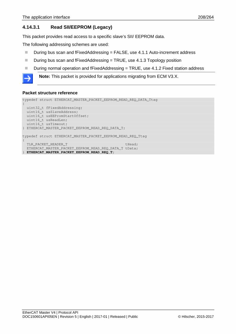
The application interface 208/264
EtherCAT Master V4 | Protocol API DOC150601API05EN | Revision 5 | English | 2017-01 | Released | Public © Hilscher, 2015-2017
4.14.3.1 Read SII/EEPROM (Legacy)
This packet provides read access to a specific slave’s SII/ EEPROM data.
The following addressing schemes are used:
During bus scan and fFixedAddressing = FALSE, use 4.1.1 Auto-increment address
During bus scan and fFixedAddressing = TRUE, use 4.1.3 Topology position
During normal operation and fFixedAddressing = TRUE, use 4.1.2 Fixed station address
Note: This packet is provided for applications migrating from ECM V3.X.
Packet structure reference typedef struct ETHERCAT_MASTER_PACKET_EEPROM_READ_REQ_DATA_Ttag { uint32_t fFixedAddressing; uint16_t usSlaveAddress; uint16_t usEEPromStartOffset; uint16_t usReadLen; uint16_t usTimeout; } ETHERCAT_MASTER_PACKET_EEPROM_READ_REQ_DATA_T; typedef struct ETHERCAT_MASTER_PACKET_EEPROM_READ_REQ_Ttag { TLR_PACKET_HEADER_T tHead; ETHERCAT_MASTER_PACKET_EEPROM_READ_REQ_DATA_T tData; } ETHERCAT_MASTER_PACKET_EEPROM_READ_REQ_T;

The application interface 209/264
EtherCAT Master V4 | Protocol API DOC150601API05EN | Revision 5 | English | 2017-01 | Released | Public © Hilscher, 2015-2017
Packet description
Structure ETHERCAT_MASTER_PACKET_EEPROM_READ_REQ_T Type: Request
Variable Type Value / range Description tHead - Structure TLR_PACKET_HEADER_T ulDest UINT32 Destination queue-handle ulSrc UINT32 Source queue-handle ulDestId UINT32 Destination End Point Identifier, specifying the final receiver of the
packet within the Destination Process. Set to 0 for the Initialization Packet
ulSrcId UINT32 Source End Point Identifier, specifying the origin of the packet inside the Source Process
ulLen UINT32 12 Packet Data Length in bytes ulId UINT32 0 ... 232-1 Packet Identification as unique number generated by the Source
Process of the Packet ulSta UINT32 See section Status/Error codes overview ulCmd UINT32 0x650040 ETHERCAT_MASTER_CMD_EEPROM_READ_REQ - Command
ulExt UINT32 0 Extension not in use, set to zero for compatibility reasons ulRout UINT32 x Routing, do not touch
tData – Structure ETHERCAT_MASTER_PACKET_EEPROM_READ_REQ_DATA_T fFixedAddressing BOOL TRUE, FALSE Addressing mode:
TRUE: use fixed addressing (configured or bus scan) FALSE: use auto increment addressing (only allowed on Bus scan)
usSlaveAddress UINT16 Valid address Slave Address (fixed or auto increment address depending on fFixedAddressing)
usEEPromStartOffset
UINT16 Word Start offset in EEPROM 0x0000 => first word (at byte offset 0) 0x0001 => second word (at byte offset 2)
usReadLen UINT16 Number of 16 bit words usTimeout UINT16 Timeout in ms
Table 160: ETHERCAT_MASTER_CMD_EEPROM_READ_REQ – Read SII/ EEPROM request (Legacy)

The application interface 210/264
EtherCAT Master V4 | Protocol API DOC150601API05EN | Revision 5 | English | 2017-01 | Released | Public © Hilscher, 2015-2017
Packet structure reference typedef struct ETHERCAT_MASTER_PACKET_EEPROM_READ_CNF_DATA_Ttag { uint32_t fFixedAddressing; uint16_t usSlaveAddress; uint16_t usEEPromStartOffset; uint16_t ausReadData[750]; } ETHERCAT_MASTER_PACKET_EEPROM_READ_CNF_DATA_T; typedef struct ETHERCAT_MASTER_PACKET_EEPROM_READ_CNF_Ttag { TLR_PACKET_HEADER_T tHead; ETHERCAT_MASTER_PACKET_EEPROM_READ_CNF_DATA_T tData; } ETHERCAT_MASTER_PACKET_EEPROM_READ_CNF_T;
Packet description
Structure ETHERCAT_MASTER_PACKET_EEPROM_READ_CNF_T Type: Confirmation
Variable Type Value / range Description tHead - Structure TLR_PACKET_HEADER_T ulDest UINT32 Destination queue handle, unchanged ulSrc UINT32 Source queue handle, unchanged ulDestId UINT32 Destination End Point Identifier, specifying the final receiver of the
packet within the Destination Process. Set to 0 for the Initialization Packet
ulSrcId UINT32 Source End Point Identifier, specifying the origin of the packet inside the Source Process
ulLen UINT32 8 + n * 2 Packet Data Length in bytes ulId UINT32 0 ... 232-1 Packet Identification, unchanged ulSta UINT32 See section Status/Error codes overview ulCmd UINT32 0x650041 ETHERCAT_MASTER_CMD_EEPROM_READ_CNF – Command
ulExt UINT32 0 Extension, reserved ulRout UINT32 x Routing information, do not change
tData – Structure ETHERCAT_MASTER_PACKET_EEPROM_READ_CNF_DATA_T fFixedAddressing
BOOL TRUE, FALSE Value from request
usSlaveAddress
UINT16 Value from request
usEEPromStartOffset
UINT16 Value from request
ausReadData[n]
UINT16[]
Words read from SII/EEPROM Actual length depends on (ulLen – 8) / 2
Table 161: ETHERCAT_MASTER_CMD_EEPROM_READ_CNF – Read SII/EEPROM confirmation (Legacy)

The application interface 211/264
EtherCAT Master V4 | Protocol API DOC150601API05EN | Revision 5 | English | 2017-01 | Released | Public © Hilscher, 2015-2017
4.14.3.2 Write SII/EEPROM (Legacy)
This packet provides write access to a specific slave’s SII/ EEPROM data.
The following addressing schemes are used:
During bus scan and fFixedAddressing = FALSE, use 4.1.1 Auto-increment address
During bus scan and fFixedAddressing = TRUE, use 4.1.3 Topology position
During normal operation and fFixedAddressing = TRUE, use 4.1.2 Fixed station address
Note: This packet is provided for applications migrating from ECM V3.X.
Packet structure reference typedef struct ETHERCAT_MASTER_PACKET_EEPROM_WRITE_REQ_DATA_Ttag { uint32_t fFixedAddressing; uint16_t usSlaveAddress; uint16_t usEEPromStartOffset; uint32_t fAssignAccessBack; uint16_t usTimeout; uint16_t ausWriteData[750]; } ETHERCAT_MASTER_PACKET_EEPROM_WRITE_REG_DATA_T; typedef struct ETHERCAT_MASTER_PACKET_EEPROM_WRITE_REQ_Ttag { TLR_PACKET_HEADER_T tHead; ETHERCAT_MASTER_PACKET_EEPROM_WRITE_REQ_DATA_T tData; } ETHERCAT_MASTER_PACKET_EEPROM_WRITE_REQ_T;

The application interface 212/264
EtherCAT Master V4 | Protocol API DOC150601API05EN | Revision 5 | English | 2017-01 | Released | Public © Hilscher, 2015-2017
Packet description
Structure ETHERCAT_MASTER_PACKET_EEPROM_WRITE_REQ_T Type: Request
Variable Type Value / range Description tHead - Structure TLR_PACKET_HEADER_T ulDest UINT32 Destination queue-handle ulSrc UINT32 Source queue-handle ulDestId UINT32 Destination End Point Identifier, specifying the final receiver of the
packet within the Destination Process. Set to 0 for the Initialization Packet
ulSrcId UINT32 Source End Point Identifier, specifying the origin of the packet inside the Source Process
ulLen UINT32 14 + n * 2 Packet Data Length in bytes ulId UINT32 0 ... 232-1 Packet Identification as unique number generated by the Source
Process of the Packet ulSta UINT32 See section Status/Error codes overview ulCmd UINT32 0x650042 ETHERCAT_MASTER_CMD_EEPROM_WRITE_REQ - Command
ulExt UINT32 0 Extension not in use, set to zero for compatibility reasons ulRout UINT32 x Routing, do not touch
tData – Structure ETHERCAT_MASTER_PACKET_EEPROM_WRITE_REQ_DATA_T fFixedAddressing BOOL TRUE, FALSE Addressing mode:
TRUE: use fixed addressing (configured or bus scan) FALSE: use auto increment addressing (only allowed on Bus scan)
usSlaveAddress UINT16 Valid address Slave Address (fixed or auto increment address depending on fFixedAddressing)
usEEPromStartOffset
UINT16 Word Start offset in EEPROM 0x0000 => first word (at byte offset 0) 0x0001 => second word (at byte offset 2)
fAssignAccessBack
BOOL
usTimeout UINT16 Timeout in ms ausWriteData[n] UINT16[
] Data to be written to SII
Actual length depends on (ulLen – 14) / 2
Table 162: ETHERCAT_MASTER_CMD_EEPROM_WRITE_REQ – Write SII/EEPROM request (Legacy)

The application interface 213/264
EtherCAT Master V4 | Protocol API DOC150601API05EN | Revision 5 | English | 2017-01 | Released | Public © Hilscher, 2015-2017
Packet structure reference typedef struct ETHERCAT_MASTER_PACKET_EEPROM_WRITE_CNF_DATA_Ttag { uint32_t fFixedAddressing; uint16_t usSlaveAddress; uint16_t usEEPromStartOffset; } ETHERCAT_MASTER_PACKET_EEPROM_WRITE_CNF_DATA_T; typedef struct ETHERCAT_MASTER_PACKET_EEPROM_WRITE_CNF_Ttag { TLR_PACKET_HEADER_T tHead; ETHERCAT_MASTER_PACKET_EEPROM_WRITE_CNF_DATA_T tData; } ETHERCAT_MASTER_PACKET_EEPROM_WRITE_CNF_T;
Packet description
Structure ETHERCAT_MASTER_PACKET_EEPROM_WRITE_CNF_T Type: Confirmation
Variable Type Value / range Description tHead - Structure TLR_PACKET_HEADER_T ulDest UINT32 Destination queue handle, unchanged ulSrc UINT32 Source queue handle, unchanged ulDestId UINT32 Destination End Point Identifier, specifying the final receiver of the packet
within the Destination Process. Set to 0 for the Initialization Packet ulSrcId UINT32 Source End Point Identifier, specifying the origin of the packet inside the
Source Process ulLen UINT32 0 Packet Data Length in bytes ulId UINT32 0 ... 232-1 Packet Identification, unchanged ulSta UINT32 See section Status/Error codes overview ulCmd UINT32 0x650043 ETHERCAT_MASTER_CMD_EEPROM_WRITE_CNF – Command
ulExt UINT32 0 Extension, reserved ulRout UINT32 x Routing information, do not change
tData – Structure ETHERCAT_MASTER_PACKET_EEPROM_WRITE_CNF_DATA_T fFixedAddressing
BOOL TRUE, FALSE Value from request
usSlaveAddress
UINT16 Value from request
usEEPromStartOffset
UINT16 Word Start offset in EEPROM 0x0000 => first word (at byte offset 0) 0x0001 => second word (at byte offset 2)
Table 163: ETHERCAT_MASTER_CMD_EEPROM_WRITE_CNF – Write SII/EEPROM confirmation (Legacy)

The application interface 214/264
EtherCAT Master V4 | Protocol API DOC150601API05EN | Revision 5 | English | 2017-01 | Released | Public © Hilscher, 2015-2017
4.15 ExtSync (since V4.3)
4.15.1 Description of ExtSync functionality ExtSync provides a means to synchronize an EtherCAT network to another time source (e.g. another EtherCAT network).
ExtSync specifics
ExtSync synchronize two networks so that the time difference between both is defined and stable.
ExtSync does not match bus cycles of two EtherCAT networks. It only ensures that a timestamp can be transformed from primary to secondary network and vice versa.
Detailed status information specific to ExtSync is provided through:
Via process data
4.11.3.7 Process data area type: ExtSync status
Via packet
4.15.2 Get ExtSync information packet

The application interface 215/264
EtherCAT Master V4 | Protocol API DOC150601API05EN | Revision 5 | English | 2017-01 | Released | Public © Hilscher, 2015-2017
4.15.2 Get ExtSync information packet This packet allows retrieving information about current ExtSync status.
Packet structure reference typedef struct ECM_IF_GET_EXT_SYNC_INFO_REQ_Ttag { TLR_PACKET_HEADER_T tHead; } ECM_IF_GET_EXT_SYNC_INFO_REQ_T;
Packet description
Structure ECM_IF_GET_EXT_SYNC_INFO_REQ_T Type: Request
Variable Type Value / range Description tHead - Structure TLR_PACKET_HEADER_T ulDest UINT32 Destination queue-handle ulSrc UINT32 Source queue-handle ulDestId UINT32 Destination End Point Identifier, specifying the final receiver of the
packet within the Destination Process. Set to 0 for the Initialization Packet
ulSrcId UINT32 Source End Point Identifier, specifying the origin of the packet inside the Source Process
ulLen UINT32 0 Packet Data Length in bytes ulId UINT32 0 ... 232-1 Packet Identification as unique number generated by the Source
Process of the Packet ulSta UINT32 See section Status/Error codes overview ulCmd UINT32 0x9E66 ECM_IF_CMD_GET_EXT_SYNC_INFO_REQ - Command
ulExt UINT32 0 Extension not in use, set to zero for compatibility reasons ulRout UINT32 x Routing, do not touch
Table 164: ECM_IF_CMD_GET_EXT_SYNC_INFO_REQ – Get ExtSync information request

The application interface 216/264
EtherCAT Master V4 | Protocol API DOC150601API05EN | Revision 5 | English | 2017-01 | Released | Public © Hilscher, 2015-2017
Packet structure reference typedef struct ECM_IF_GET_EXT_SYNC_INFO_CNF_DATA_Ttag { uint32_t ulExtSyncInfoFlags; uint64_t ullInternalTimestampNs; uint64_t ullExternalTimestampNs; int32_t lTimeControlValueBySlave; uint16_t usExtSyncStationAddress; uint64_t ullDcToExtTimeOffsetNs; uint32_t ulLastUpdateDiffNs; int32_t lLastControlDeltaDiffNs; int32_t lLastControlDeltaDeltaDiffNs; uint16_t usControlledStationAddress; uint32_t ulExtSyncUpdateCount; } ECM_IF_GET_EXT_SYNC_INFO_CNF_DATA_T; typedef struct ECM_IF_GET_EXT_SYNC_INFO_CNF_Ttag { TLR_PACKET_HEADER_T tHead; ECM_IF_GET_EXT_SYNC_INFO_CNF_DATA_T tData; } ECM_IF_GET_EXT_SYNC_INFO_CNF_T;

The application interface 217/264
EtherCAT Master V4 | Protocol API DOC150601API05EN | Revision 5 | English | 2017-01 | Released | Public © Hilscher, 2015-2017
Packet description
Structure ECM_IF_GET_EXT_SYNC_INFO_CNF_T Type: Confirmation
Variable Type Value / range Description tHead - Structure TLR_PACKET_HEADER_T ulDest UINT32 Destination queue handle, unchanged ulSrc UINT32 Source queue handle, unchanged ulDestId UINT32 Destination End Point Identifier, specifying the final receiver of the
packet within the Destination Process. Set to 0 for the Initialization Packet
ulSrcId UINT32 Source End Point Identifier, specifying the origin of the packet inside the Source Process
ulLen UINT32 0 Packet Data Length in bytes ulId UINT32 0 ... 232-1 Packet Identification, unchanged ulSta UINT32 See section Status/Error codes overview ulCmd UINT32 0x9E67 ECM_IF_CMD_GET_EXT_SYNC_INFO_CNF – Command
ulExt UINT32 0 Extension, reserved ulRout UINT32 x Routing information, do not change
tData – Structure ECM_IF_GET_EXT_SYNC_INFO_CNF_DATA_T ulExtSyncInfoFlags
UINT32 See Table 166: Parameter ulExtSyncInfoFlags
ullInternalTimestampNs
UINT64 Last known 32 bit / 64 bit own network DC timestamp as seen by ExtSync device
ullExternalTimestampNs
UINT64 Last known 32 bit / 64 bit external timestamp as seen by ExtSync device
lTimeControlValueBySlave
INT32 Time value provided from ExtSync device data Not used by master for actual ExtSync implementation
usExtSyncStationAddress
UINT16 Fixed station address of Ext Sync device See 4.1.2 Fixed station address
ullDcToExtTimeOffsetNs
UINT64 Time difference between this network and the other network providing the ExtSync base time.
Relationship of timestamps:
DcToExtTimeOffsetNs = ExternalTimestampNs - InternalTimestampNs
ulLastUpdateDiffNs
UINT32 Last delta time between ExtSync processing in ns
lLastControlDeltaDiffNs
INT32 ExtSync diagnostic data. Internal use
lLastControlDeltaDeltaDiffNs
INT32 ExtSync diagnostic data. Internal use
usControlledStationAddress
UINT16 Fixed station address of DC reference clock
See 4.1.2 Fixed station address ulExtSyncUpdateCount
UINT32 Counter of processed ExtSync updates
Table 165: ECM_IF_CMD_GET_EXT_SYNC_INFO_CNF – Get ExtSync information confirmation

The application interface 218/264
EtherCAT Master V4 | Protocol API DOC150601API05EN | Revision 5 | English | 2017-01 | Released | Public © Hilscher, 2015-2017
Definition of ulExtSyncInfoFlags
Bits Name (Bit mask) Description
31 MSK_ECM_IF_EXT_SYNC_INFO_FLAGS_EXT_DEVICE_CONFIGURED (0x80000000)
Ext Sync device has been configured
30 MSK_ECM_IF_EXT_SYNC_INFO_FLAGS_EXT_DEVICE_ACTIVE (0x40000000)
Master is actively using External synchronization on device
29 MSK_ECM_IF_EXT_SYNC_INFO_FLAGS_DC_TO_EXT_OFFSET_VALID (0x20000000)
ullDcToExtTimeOffsetNs is valid
28 … 24 Reserved reserved
23 … 16 Used internally Used internally
15 MSK_ECM_IF_EXT_SYNC_INFO_FLAGS_EXT_DEVICE_CONNECTED_AS_SLAVE (0x00008000)
Ext Sync Device is connected as slave
14 … 6 Reserved Reserved for future use
5 MSK_ECM_IF_EXT_SYNC_INFO_FLAGS_SYNC_MODE_MASTER (0x00000020)
Master is providing ExtSync to other network
4 MSK_ECM_IF_EXT_SYNC_INFO_FLAGS_EXT_DEVICE_NOT_CONNECTED (0x00000010)
ExtSync device is not connected when bit is set
3 Reserved Reserved
2 MSK_ECM_IF_EXT_SYNC_INFO_FLAGS_IS_64BIT (0x00000004)
ExtSync timestamp size
If not set, the timestamp has 32 bit. If set, the timestamp has 64 bit.
1 Reserved Reserved
0 MSK_ECM_IF_EXT_SYNC_INFO_FLAGS_SYNC_MODE_SLAVE (0x00000001)
Master is using ExtSync reference provided by other network
Table 166: Parameter ulExtSyncInfoFlags

The application interface 219/264
EtherCAT Master V4 | Protocol API DOC150601API05EN | Revision 5 | English | 2017-01 | Released | Public © Hilscher, 2015-2017
4.16 Bus scan
4.16.1 Packet parameter ulPortState
The port state specifies what ports are active on a given slave.
The following table outlines what port state flags are defined:
Bits Name of bitmask / Description 15 DL Status: Communication on Port 3 14 DL Status: Communication on Port 2 13 DL Status: Communication on Port 1 12 DL Status: Communication on Port 0 11 DL Status: Loop closed on Port 3 10 DL Status: Loop closed on Port 2 9 DL Status: Loop closed on Port 1 8 DL Status: Loop closed on Port 0 7 DL Status: Link on Port 3 6 DL Status: Link on Port 2 5 DL Status: Link on Port 1 4 DL Status: Link on Port 0 3 Slave is connected to Port 3 2 Slave is connected to Port 2 1 Slave is connected to Port 1 0 Slave is connected to Port 0
Table 167: Meaning of ulPortState
Bits 0 to 3 are generated by the following operation on Bits 4-15: ulLowNibble = ((~(ulPortState >> 8)) & (ulPortState >> 12));
If a port does not exist, all bits of a given port are set to 0.
The port order of an EtherCAT slave is 0, 3, 1 and 2.

The application interface 220/264
EtherCAT Master V4 | Protocol API DOC150601API05EN | Revision 5 | English | 2017-01 | Released | Public © Hilscher, 2015-2017
4.16.2 Generic bus scan The generic bus scan provides a common definition of how to handle the service in detail. Therefore, this chapter will only present the specifics related to the EtherCAT master. Its basic implementation is done according to document Automatic Bus scan which is listed in 1.8 References.
4.16.2.1 Relation: Topology Address and Auto-Increment Address in generic bus scan
The device index in generic bus scan is mapped to the auto-increment addresses according the following rules in UInt16 calculation: TopologyAddress = 1 – AutoInc-Address AutoInc-Address = 1 – Topology-Address
First slave in topology has topology address 1 and Auto-Inc address 0.
Therefore, the application can directly use the device index for accessing a particular slave’s service channel which is based on topology address as well.
One reason for this mapping is to have access to acyclic access features during bus scan. This will allow extracting more details from the slave on an as needed basis.
This section is a short summary of the following two sections provided earlier:
4.1.1 Auto-increment address
4.1.3 Topology position
4.16.2.2 Acyclic services access
The generic bus scan allows accessing all acyclic services that can be reached on a slave when being in PREOP.
The used addressing scheme when using generic bus scan is topology position (see 4.1.3 Topology position) for all services including retrieving Identity information via 4.16.2.4 Get device info service.
The following acyclic services can be used with restrictions in generic bus scan:
4.7 CoE services
4.9 SoE services
4.14.1 ESC register access
4.14.2 ESC SII access
The following legacy acyclic services can only be used with fixed station address mode (effectively using topology position during generic bus scan):
4.14.3 Legacy ESC SII access (ECM V3.X API)
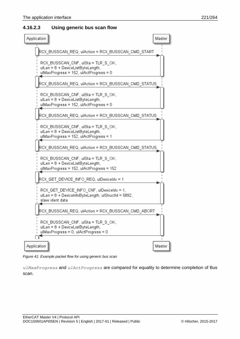
The application interface 221/264
EtherCAT Master V4 | Protocol API DOC150601API05EN | Revision 5 | English | 2017-01 | Released | Public © Hilscher, 2015-2017
4.16.2.3 Using generic bus scan flow
Figure 41: Example packet flow for using generic bus scan
ulMaxProgress and ulActProgress are compared for equality to determine completion of Bus scan.

The application interface 222/264
EtherCAT Master V4 | Protocol API DOC150601API05EN | Revision 5 | English | 2017-01 | Released | Public © Hilscher, 2015-2017
4.16.2.4 Get device info service
This service is used for requesting the current device information of a connected slave and has EtherCAT specific parts which will be shown here.
The following addressing schemes are used:
4.1.3 Topology position
Packet structure reference typedef struct RCX_GET_DEVICE_INFO_REQ_DATA_Ttag { uint32_t ulDeviceIdx; } RCX_GET_DEVICE_INFO_REQ_DATA_T; typedef struct RCX_GET_DEVICE_INFO_REQ_Ttag { TLR_PACKET_HEADER_T tHead; RCX_GET_DEVICE_INFO_REQ_DATA_T tData; } RCX_GET_DEVICE_INFO_REQ_T;
Packet description
Structure RCX_GET_DEVICE_INFO_REQ_T Type: Request
Variable Type Value / range Description tHead - Structure TLR_PACKET_HEADER_T ulDest UINT32 Destination queue-handle ulSrc UINT32 Source queue-handle ulDestId UINT32 Destination End Point Identifier, specifying the final receiver of the
packet within the Destination Process. Set to 0 for the Initialization Packet
ulSrcId UINT32 Source End Point Identifier, specifying the origin of the packet inside the Source Process
ulLen UINT32 4 Packet Data Length in bytes ulId UINT32 0 ... 232-1 Packet Identification as unique number generated by the Source
Process of the Packet ulSta UINT32 See section Status/Error codes overview ulCmd UINT32 0x2F24 RCX_GET_DEVICE_INFO_REQ - Command
ulExt UINT32 0 Extension not in use, set to zero for compatibility reasons ulRout UINT32 x Routing, do not touch tData - Structure RCX_GET_DEVICE_INFO_REQ_DATA_T ulDeviceIdx UINT32 Device index references to topology position based on 0 to number of
slaves - 1
Table 168: RCX_GET_DEVICE_INFO_REQ – Get device info request

The application interface 223/264
EtherCAT Master V4 | Protocol API DOC150601API05EN | Revision 5 | English | 2017-01 | Released | Public © Hilscher, 2015-2017
Packet structure reference typedef struct RCX_GET_DEVICE_INFO_CNF_DATA_Ttag { uint32_t ulDeviceIdx; uint32_t ulStructId; } RCX_GET_DEVICE_INFO_CNF_DATA_T; typedef struct ETHERCAT_MASTER_BUS_SCAN_INFO_Ttag { uint32_t ulVendorId; uint32_t ulProductCode; uint32_t ulRevisionNumber; uint32_t ulSerialNumber; uint32_t ulPortState; } ETHERCAT_MASTER_BUS_SCAN_INFO_T; typedef struct RCX_GET_DEVICE_INFO_CNF_Ttag { TLR_PACKET_HEADER_T tHead; RCX_GET_DEVICE_INFO_CNF_DATA_T tData; ETHERCAT_MASTER_BUS_SCAN_INFO_T tDevInfoData; } RCX_GET_DEVICE_INFO_CNF_T;
Note: tDevInfoData is not part of the RCX_GET_DEVICE_INFO_CNF_T. It is merely shown where it is placed. It must be addressed by ((&ptPck->tData) + 1).

The application interface 224/264
EtherCAT Master V4 | Protocol API DOC150601API05EN | Revision 5 | English | 2017-01 | Released | Public © Hilscher, 2015-2017
Packet description
Structure RCX_GET_DEVICE_INFO_CNF_T Type: Confirmation
Variable Type Value / range Description tHead - Structure TLR_PACKET_HEADER_T ulDest UINT32 Destination queue-handle ulSrc UINT32 Source queue-handle ulDestId UINT32 Destination End Point Identifier, specifying the final receiver of the
packet within the Destination Process. Set to 0 for the Initialization Packet
ulSrcId UINT32 Source End Point Identifier, specifying the origin of the packet inside the Source Process
ulLen UINT32 4 on success or 0 in case of error
Packet Data Length in bytes
ulId UINT32 0 ... 232-1 Packet Identification as unique number generated by the Source Process of the Packet
ulSta UINT32 See section Status/Error codes overview ulCmd UINT32 0x2F25 RCX_GET_DEVICE_INFO_CNF - Command
ulExt UINT32 0 Extension not in use, set to zero for compatibility reasons ulRout UINT32 x Routing, do not touch tData - Structure RCX_GET_DEVICE_INFO_CNF_DATA_T ulDeviceIdx UINT32 Device Index ulStructId UINT32 5892 Structure Id
tDevInfoData – Structure ETHERCAT_MASTER_BUS_SCAN_INFO_T
ulVendorId UINT32 Vendor Id ulProductCode UINT32 Product Code ulRevisionNumber
UINT32 Revision Number
ulSerialNumber UINT32 Serial Number ulPortState UINT32 For details see 4.16.1 Packet parameter ulPortState
Table 169: RCX_GET_DEVICE_INFO_CNF – Get device info confirmation

The application interface 225/264
EtherCAT Master V4 | Protocol API DOC150601API05EN | Revision 5 | English | 2017-01 | Released | Public © Hilscher, 2015-2017
4.16.3 Legacy bus scan
4.16.3.1 Limits of legacy bus scan
The legacy bus scan is limited to retrieving slave identity data only. It cannot access acyclic services. Therefore, it cannot be used for scanning Modular Device Profile devices.
For new applications, please use the 4.16.2 Generic bus scan.
. The legacy bus scan is only provided for applications that have been originally developed for ECM V3.X.

The application interface 226/264
EtherCAT Master V4 | Protocol API DOC150601API05EN | Revision 5 | English | 2017-01 | Released | Public © Hilscher, 2015-2017
4.16.3.2 Using legacy bus scan
The following sequence of packets applies to the legacy bus scan mechanism:
Figure 42: Using legacy bus scan

The application interface 227/264
EtherCAT Master V4 | Protocol API DOC150601API05EN | Revision 5 | English | 2017-01 | Released | Public © Hilscher, 2015-2017
4.16.3.3 Start bus scan service (Legacy)
The bus scan is started using the packet ETHERCAT_MASTER_CMD_START_BUS_SCAN_REQ. After the confirmation was returned, the slave information can be read out. This is done by using the packet ETHERCAT_MASTER_CMD_GET_BUS_SCAN_INFO_REQ.
If the master does not find any slaves within given timeout (e. g. no Ethernet link or no slaves attached) the packet is returned with an error code.
Note: This packet is provided for applications migrating from ECM V3.X.
Packet structure reference Typedef struct ETHERCAT_MASTER_PACKET_START_BUS_SCAN_REQ_DATA_Ttag { uint32_t ulTimeout; } ETHERCAT_MASTER_PACKET_START_BUS_SCAN_REQ_DATA_T; typedef struct ETHERCAT_MASTER_PACKET_START_BUS_SCAN_REQ_Ttag { TLR_PACKET_HEADER_T tHead; ETHERCAT_MASTER_PACKET_START_BUS_SCAN_REQ_DATA_T tData; } ETHERCAT_MASTER_PACKET_START_BUS_SCAN_REQ_T;
Packet description
Structure ETHERCAT_MASTER_PACKET_START_BUS_SCAN_REQ_T Type: Request
Variable Type Value / range Description tHead - Structure TLR_PACKET_HEADER_T
ulDest UINT32 Destination queue-handle ulSrc UINT32 Source queue-handle ulDestId UINT32 Destination End Point Identifier, specifying the final receiver of the
packet within the Destination Process. Set to 0 for the Initialization Packet
ulSrcId UINT32 Source End Point Identifier, specifying the origin of the packet inside the Source Process
ulLen UINT32 0 Packet Data Length in bytes ulId UINT32 0 ... 232-1 Packet Identification as unique number generated by the Source
Process of the Packet ulSta UINT32 See section Status/Error codes overview ulCmd UINT32 0x650020 ETHERCAT_MASTER_CMD_START_BUS_SCAN_REQ - Command
ulExt UINT32 0 Extension not in use, set to zero for compatibility reasons ulRout UINT32 x Routing, do not touch tData – Structure ETHERCAT_MASTER_PACKET_START_BUS_SCAN_REQ_DATA_T ulTimeout UINT32 Timeout in ms
Table 170: ETHERCAT_MASTER_CMD_START_BUS_SCAN_REQ – (Re)start the bus scan request

The application interface 228/264
EtherCAT Master V4 | Protocol API DOC150601API05EN | Revision 5 | English | 2017-01 | Released | Public © Hilscher, 2015-2017
Packet structure reference typedef struct ETHERCAT_MASTER_PACKET_START_BUS_SCAN_CNF_DATA_Ttag { uint32_t ulFoundSlaves; } ETHERCAT_MASTER_PACKET_START_BUS_SCAN_CNF_DATA_T; typedef struct ETHERCAT_MASTER_PACKET_BUS_SCAN_CNF_Ttag { TLR_PACKET_HEADER_T tHead; ETHERCAT_MASTER_PACKET_START_BUS_SCAN_CNF_DATA_T tData; } ETHERCAT_MASTER_PACKET_START_BUS_SCAN_CNF_T;
Packet description
Structure ETHERCAT_MASTER_PACKET_START_BUS_SCAN_CNF_T Type: Confirmation
Variable Type Value / range Description tHead - Structure TLR_PACKET_HEADER_T ulDest UINT32 Destination queue-handle ulSrc UINT32 Source queue-handle ulDestId UINT32 Destination End Point Identifier, specifying the final receiver of the
packet within the Destination Process. Set to 0 for the Initialization Packet
ulSrcId UINT32 Source End Point Identifier, specifying the origin of the packet inside the Source Process
ulLen UINT32 4 on success or 0 in case of error
Packet Data Length in bytes
ulId UINT32 0 ... 232-1 Packet Identification as unique number generated by the Source Process of the Packet
ulSta UINT32 See section Status/Error codes overview ulCmd UINT32 0x650021 ETHERCAT_MASTER_START_BUS_SCAN_CNF - Command
ulExt UINT32 0 Extension not in use, set to zero for compatibility reasons ulRout UINT32 x Routing, do not touch tData - Structure ETHERCAT_MASTER_PACKET_START_BUS_SCAN_CNF_DATA_T ulFoundSlaves UINT32 Number of slaves found during bus scan
Table 171: ETHERCAT_MASTER_CMD_START_BUS_SCAN_CNF – (Re)start the bus scan confirmation

The application interface 229/264
EtherCAT Master V4 | Protocol API DOC150601API05EN | Revision 5 | English | 2017-01 | Released | Public © Hilscher, 2015-2017
4.16.3.4 Get bus scan results service (Legacy)
This packet provides access to the data being collected by a preceding bus scan.
The actual confirmation packet will carry the following information which is related to the Identity and topology:
Vendor Id
Product Code
Revision Number
Serial Number
Port State
The following addressing schemes are used:
4.1.1 Auto-increment address
Note: This packet is provided for applications migrating from ECM V3.X.
Packet structure reference typedef struct ETHERCAT_MASTER_PACKET_GET_BUS_SCAN_INFO_REQ_DATA_Ttag { uint16_t usAutoIncAddr; } ETHERCAT_MASTER_PACKET_GET_BUS_SCAN_INFO_REQ_DATA_T; typedef struct ETHERCAT_MASTER_PACKET_GET_BUS_SCAN_INFO_REQ_Ttag { TLR_PACKET_HEADER_T tHead; ETHERCAT_MASTER_PACKET_GET_BUS_SCAN_INFO_REQ_DATA_T tData; } ETHERCAT_MASTER_PACKET_GET_BUS_SCAN_INFO_REQ_T;

The application interface 230/264
EtherCAT Master V4 | Protocol API DOC150601API05EN | Revision 5 | English | 2017-01 | Released | Public © Hilscher, 2015-2017
Packet description
Structure ETHERCAT_MASTER_PACKET_GET_BUS_SCAN_INFO_REQ_T Type: Request
Variable Type Value / range
Description
tHead - Structure TLR_PACKET_HEADER_T
ulDest UINT32 Destination queue-handle ulSrc UINT32 Source queue-handle ulDestId UINT32 Destination End Point Identifier, specifying the final receiver of the
packet within the Destination Process. Set to 0 for the Initialization Packet
ulSrcId UINT32 Source End Point Identifier, specifying the origin of the packet inside the Source Process
ulLen UINT32 2 Packet Data Length in bytes ulId UINT32 0 ... 232-1 Packet Identification as unique number generated by the Source
Process of the Packet ulSta UINT32 See section Status/Error codes overview ulCmd UINT32 0x650022 ETHERCAT_MASTER_CMD_GET_BUS_SCAN_INFO_REQ - Command
ulExt UINT32 0 Extension not in use, set to zero for compatibility reasons ulRout UINT32 x Routing, do not touch tData - Structure ETHERCAT_MASTER_PACKET_GET_BUS_SCAN_INFO_REQ_DATA_T usAutoIncAddr UINT16 0x0000
0xFFFF 0xFFFE …
Use the 4.1.1 Auto-increment address for addressing slaves during Legacy Bus scan.
Table 172: ETHERCAT_MASTER_CMD_GET_BUS_SCAN_INFO_REQ – Get results from bus scan request
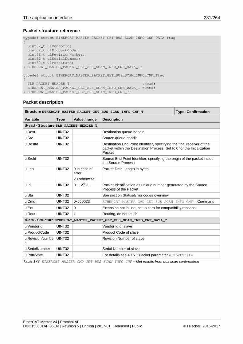
The application interface 231/264
EtherCAT Master V4 | Protocol API DOC150601API05EN | Revision 5 | English | 2017-01 | Released | Public © Hilscher, 2015-2017
Packet structure reference typedef struct ETHERCAT_MASTER_PACKET_GET_BUS_SCAN_INFO_CNF_DATA_Ttag { uint32_t ulVendorId; uint32_t ulProductCode; uint32_t ulRevisionNumber; uint32_t ulSerialNumber; uint32_t ulPortState; } ETHERCAT_MASTER_PACKET_GET_BUS_SCAN_INFO_CNF_DATA_T; typedef struct ETHERCAT_MASTER_PACKET_GET_BUS_SCAN_INFO_CNF_Ttag { TLR_PACKET_HEADER_T tHead; ETHERCAT_MASTER_PACKET_GET_BUS_SCAN_INFO_CNF_DATA_T tData; } ETHERCAT_MASTER_PACKET_GET_BUS_SCAN_INFO_CNF_T;
Packet description
Structure ETHERCAT_MASTER_PACKET_GET_BUS_SCAN_INFO_CNF_T Type: Confirmation
Variable Type Value / range Description tHead - Structure TLR_PACKET_HEADER_T ulDest UINT32 Destination queue-handle ulSrc UINT32 Source queue-handle ulDestId UINT32 Destination End Point Identifier, specifying the final receiver of the
packet within the Destination Process. Set to 0 for the Initialization Packet
ulSrcId UINT32 Source End Point Identifier, specifying the origin of the packet inside the Source Process
ulLen UINT32 0 in case of error 20 otherwise
Packet Data Length in bytes
ulId UINT32 0 ... 232-1 Packet Identification as unique number generated by the Source Process of the Packet
ulSta UINT32 See section Status/Error codes overview ulCmd UINT32 0x650023 ETHERCAT_MASTER_CMD_GET_BUS_SCAN_INFO_CNF - Command
ulExt UINT32 0 Extension not in use, set to zero for compatibility reasons ulRout UINT32 x Routing, do not touch tData - Structure ETHERCAT_MASTER_PACKET_GET_BUS_SCAN_INFO_CNF_DATA_T ulVendorId UINT32 Vendor Id of slave ulProductCode UINT32 Product Code of slave ulRevisionNumber
UINT32 Revision Number of slave
ulSerialNumber UINT32 Serial Number of slave ulPortState UINT32 For details see 4.16.1 Packet parameter ulPortState
Table 173: ETHERCAT_MASTER_CMD_GET_BUS_SCAN_INFO_CNF – Get results from bus scan confirmation
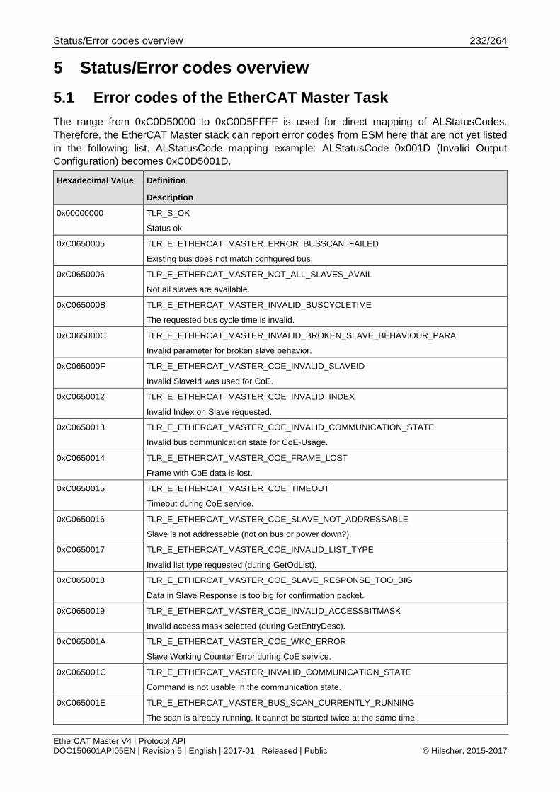
Status/Error codes overview 232/264
EtherCAT Master V4 | Protocol API DOC150601API05EN | Revision 5 | English | 2017-01 | Released | Public © Hilscher, 2015-2017
5 Status/Error codes overview 5.1 Error codes of the EtherCAT Master Task The range from 0xC0D50000 to 0xC0D5FFFF is used for direct mapping of ALStatusCodes. Therefore, the EtherCAT Master stack can report error codes from ESM here that are not yet listed in the following list. ALStatusCode mapping example: ALStatusCode 0x001D (Invalid Output Configuration) becomes 0xC0D5001D.
Hexadecimal Value Definition
Description
0x00000000 TLR_S_OK
Status ok
0xC0650005 TLR_E_ETHERCAT_MASTER_ERROR_BUSSCAN_FAILED
Existing bus does not match configured bus.
0xC0650006 TLR_E_ETHERCAT_MASTER_NOT_ALL_SLAVES_AVAIL
Not all slaves are available.
0xC065000B TLR_E_ETHERCAT_MASTER_INVALID_BUSCYCLETIME
The requested bus cycle time is invalid.
0xC065000C TLR_E_ETHERCAT_MASTER_INVALID_BROKEN_SLAVE_BEHAVIOUR_PARA
Invalid parameter for broken slave behavior.
0xC065000F TLR_E_ETHERCAT_MASTER_COE_INVALID_SLAVEID
Invalid SlaveId was used for CoE.
0xC0650012 TLR_E_ETHERCAT_MASTER_COE_INVALID_INDEX
Invalid Index on Slave requested.
0xC0650013 TLR_E_ETHERCAT_MASTER_COE_INVALID_COMMUNICATION_STATE
Invalid bus communication state for CoE-Usage.
0xC0650014 TLR_E_ETHERCAT_MASTER_COE_FRAME_LOST
Frame with CoE data is lost.
0xC0650015 TLR_E_ETHERCAT_MASTER_COE_TIMEOUT
Timeout during CoE service.
0xC0650016 TLR_E_ETHERCAT_MASTER_COE_SLAVE_NOT_ADDRESSABLE
Slave is not addressable (not on bus or power down?).
0xC0650017 TLR_E_ETHERCAT_MASTER_COE_INVALID_LIST_TYPE
Invalid list type requested (during GetOdList).
0xC0650018 TLR_E_ETHERCAT_MASTER_COE_SLAVE_RESPONSE_TOO_BIG
Data in Slave Response is too big for confirmation packet.
0xC0650019 TLR_E_ETHERCAT_MASTER_COE_INVALID_ACCESSBITMASK
Invalid access mask selected (during GetEntryDesc).
0xC065001A TLR_E_ETHERCAT_MASTER_COE_WKC_ERROR
Slave Working Counter Error during CoE service.
0xC065001C TLR_E_ETHERCAT_MASTER_INVALID_COMMUNICATION_STATE
Command is not usable in the communication state.
0xC065001E TLR_E_ETHERCAT_MASTER_BUS_SCAN_CURRENTLY_RUNNING
The scan is already running. It cannot be started twice at the same time.

Status/Error codes overview 233/264
EtherCAT Master V4 | Protocol API DOC150601API05EN | Revision 5 | English | 2017-01 | Released | Public © Hilscher, 2015-2017
Hexadecimal Value Definition
Description
0xC065001F TLR_E_ETHERCAT_MASTER_BUS_SCAN_TIMEOUT
Timeout during bus scan. But at least a link is established.
0xC0650020 TLR_E_ETHERCAT_MASTER_BUS_SCAN_NOT_READY_YET
The bus scan was not started before or is not finish yet.
0xC0650021 TLR_E_ETHERCAT_MASTER_BUS_SCAN_INVALID_SLAVE
The requested slave is invalid.
0xC0650022 TLR_E_ETHERCAT_MASTER_COE_INVALIDACCESS
Slave does not allow reading or writing (CoE-Access).
0xC0650023 TLR_E_ETHERCAT_MASTER_COE_NO_MBX_SUPPORT
Slave does not support a mailbox.
0xC0650024 TLR_E_ETHERCAT_MASTER_COE_NO_COE_SUPPORT
Slave does not support CoE.
0xC0650025 TLR_E_ETHERCAT_MASTER_TASK_CREATION_FAILED
Task could not be created during runtime.
0xC0650026 TLR_E_ETHERCAT_MASTER_INVALID_SLAVE_SM_CONFIGURATION
The Sync Manager configuration of a slave is invalid.
0xC0650027 TLR_E_ETHERCAT_MASTER_SDO_ABORTCODE_TOGGLE
SDO abort code: Toggle bit not alternated.
0xC0650028 TLR_E_ETHERCAT_MASTER_SDO_ABORTCODE_TIMEOUT
SDO abort code: SDO protocol timed out.
0xC0650029 TLR_E_ETHERCAT_MASTER_SDO_ABORTCODE_CCS_SCS
SDO abort code: Client/server command specifier not valid or unknown.
0xC065002A TLR_E_ETHERCAT_MASTER_SDO_ABORTCODE_BLK_SIZE
SDO abort code: Invalid block size (block mode only).
0xC065002B TLR_E_ETHERCAT_MASTER_SDO_ABORTCODE_SEQNO
SDO abort code: Invalid sequence number (block mode only).
0xC065002C TLR_E_ETHERCAT_MASTER_SDO_ABORTCODE_CRC
SDO abort code: CRC error (block mode only).
0xC065002D TLR_E_ETHERCAT_MASTER_SDO_ABORTCODE_MEMORY
SDO abort code: Out of memory.
0xC065002E TLR_E_ETHERCAT_MASTER_SDO_ABORTCODE_ACCESS
SDO abort code: Unsupported access to an object.
0xC065002F TLR_E_ETHERCAT_MASTER_SDO_ABORTCODE_WRITEONLY
SDO abort code: Attempt to read a write only object.
0xC0650030 TLR_E_ETHERCAT_MASTER_SDO_ABORTCODE_READONLY
SDO abort code: Attempt to write a read only object.
0xC0650031 TLR_E_ETHERCAT_MASTER_SDO_ABORTCODE_INDEX
SDO abort code: Object does not exist in the object dictionary.
0xC0650032 TLR_E_ETHERCAT_MASTER_SDO_ABORTCODE_PDO_MAP
SDO abort code: Object cannot be mapped to the PDO.
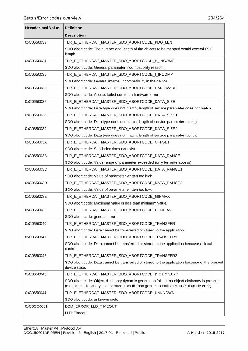
Status/Error codes overview 234/264
EtherCAT Master V4 | Protocol API DOC150601API05EN | Revision 5 | English | 2017-01 | Released | Public © Hilscher, 2015-2017
Hexadecimal Value Definition
Description
0xC0650033 TLR_E_ETHERCAT_MASTER_SDO_ABORTCODE_PDO_LEN
SDO abort code: The number and length of the objects to be mapped would exceed PDO length.
0xC0650034 TLR_E_ETHERCAT_MASTER_SDO_ABORTCODE_P_INCOMP
SDO abort code: General parameter incompatibility reason.
0xC0650035 TLR_E_ETHERCAT_MASTER_SDO_ABORTCODE_I_INCOMP
SDO abort code: General internal incompatibility in the device.
0xC0650036 TLR_E_ETHERCAT_MASTER_SDO_ABORTCODE_HARDWARE
SDO abort code: Access failed due to an hardware error.
0xC0650037 TLR_E_ETHERCAT_MASTER_SDO_ABORTCODE_DATA_SIZE
SDO abort code: Data type does not match, length of service parameter does not match.
0xC0650038 TLR_E_ETHERCAT_MASTER_SDO_ABORTCODE_DATA_SIZE1
SDO abort code: Data type does not match, length of service parameter too high.
0xC0650039 TLR_E_ETHERCAT_MASTER_SDO_ABORTCODE_DATA_SIZE2
SDO abort code: Data type does not match, length of service parameter too low.
0xC065003A TLR_E_ETHERCAT_MASTER_SDO_ABORTCODE_OFFSET
SDO abort code: Sub-index does not exist.
0xC065003B TLR_E_ETHERCAT_MASTER_SDO_ABORTCODE_DATA_RANGE
SDO abort code: Value range of parameter exceeded (only for write access).
0xC065003C TLR_E_ETHERCAT_MASTER_SDO_ABORTCODE_DATA_RANGE1
SDO abort code: Value of parameter written too high.
0xC065003D TLR_E_ETHERCAT_MASTER_SDO_ABORTCODE_DATA_RANGE2
SDO abort code: Value of parameter written too low.
0xC065003E TLR_E_ETHERCAT_MASTER_SDO_ABORTCODE_MINMAX
SDO abort code: Maximum value is less than minimum value.
0xC065003F TLR_E_ETHERCAT_MASTER_SDO_ABORTCODE_GENERAL
SDO abort code: general error.
0xC0650040 TLR_E_ETHERCAT_MASTER_SDO_ABORTCODE_TRANSFER
SDO abort code: Data cannot be transferred or stored to the application.
0xC0650041 TLR_E_ETHERCAT_MASTER_SDO_ABORTCODE_TRANSFER1
SDO abort code: Data cannot be transferred or stored to the application because of local control.
0xC0650042 TLR_E_ETHERCAT_MASTER_SDO_ABORTCODE_TRANSFER2
SDO abort code: Data cannot be transferred or stored to the application because of the present device state.
0xC0650043 TLR_E_ETHERCAT_MASTER_SDO_ABORTCODE_DICTIONARY
SDO abort code: Object dictionary dynamic generation fails or no object dictionary is present (e.g. object dictionary is generated from file and generation fails because of an file error).
0xC0650044 TLR_E_ETHERCAT_MASTER_SDO_ABORTCODE_UNKNOWN
SDO abort code: unknown code.
0xC0CC0001 ECM_ERROR_LLD_TIMEOUT
LLD: Timeout

Status/Error codes overview 235/264
EtherCAT Master V4 | Protocol API DOC150601API05EN | Revision 5 | English | 2017-01 | Released | Public © Hilscher, 2015-2017
Hexadecimal Value Definition
Description
0xC0CC0003 ECM_ERROR_LLD_UNSUPPORTED_COMMAND
LLD: Unsupported command
0xC0CC0004 ECM_ERROR_LLD_DUPLICATE_FIXED_STATION_ADDRESS
LLD: Duplicate fixed station address
0xC0CC0005 ECM_ERROR_LLD_SII_CHECKSUM_ERROR
LLD: SII Checksum Error
0xC0CC0006 ECM_ERROR_LLD_SII_EEPROM_LOADING_ERROR
LLD: SII EEPROM Loading Error
0xC0CC0007 ECM_ERROR_LLD_SII_MISSING_ERROR_ACK
LLD: SII Missing Error Ack
0xC0CC0008 ECM_ERROR_LLD_STATE_CHANGE_FAILED
LLD: State Change Failed
0xC0CC0009 ECM_ERROR_LLD_UNEXPECTED_AL_STATUS
LLD: Unexpected AL Status
0xC0CC000A ECM_ERROR_LLD_UNEXPECTED_WKC
LLD: Unexpected WKC
0xC0CC000B ECM_ERROR_LLD_MAILBOX_NOT_AVAILABLE
LLD: Mailbox not available
0xC0CC000C ECM_ERROR_LLD_MAILBOX_MESSAGE_TOO_LARGE
LLD: Mailbox message too large
0xC0CC000D ECM_ERROR_LLD_CONFIGURATION_IN_PROGRESS
LLD: Configuration in progress
0xC0CC000E ECM_ERROR_LLD_TOO_MANY_CYCLIC_FRAMES
LLD: Too many cyclic frames
0xC0CC000F ECM_ERROR_LLD_CYCLIC_FRAME_EXCEEDS_MTU
LLD: Cyclic frame exceeds MTU
0xC0CC0010 ECM_ERROR_LLD_INVALID_CYCLIC_TELEGRAM_CONFIG
LLD: Invalid cyclic telegram config
0xC0CC0011 ECM_ERROR_LLD_BUILDING_COPY_ROUTINES_FAILED
LLD: Building copy routines failed
0xC0CC0012 ECM_ERROR_LLD_UNSUPPORTED_SLAVE_STATION_ADDRESS
LLD: Unsupported slave station address
0xC0CC0013 ECM_ERROR_LLD_STATION_ADDRESS_NOT_ALLOWED
LLD: Station Address not allowed
0xC0CC0014 ECM_ERROR_LLD_INVALID_STD_TX_MBX_PHYS_OFFSET
LLD: Invalid Std TxMbx PhysOffset
0xC0CC0015 ECM_ERROR_LLD_INVALID_STD_RX_MBX_PHYS_OFFSET
LLD: Invalid Std Rx Mbx PhysOffset
0xC0CC0016 ECM_ERROR_LLD_INVALID_BOOT_TX_MBX_PHYS_OFFSET
LLD: Invalid BOOT Rx Mbx PhysOffset
0xC0CC0017 ECM_ERROR_LLD_INVALID_BOOT_RX_MBX_PHYS_OFFSET
LLD: Invalid BOOT Tx Mbx PhysOffset
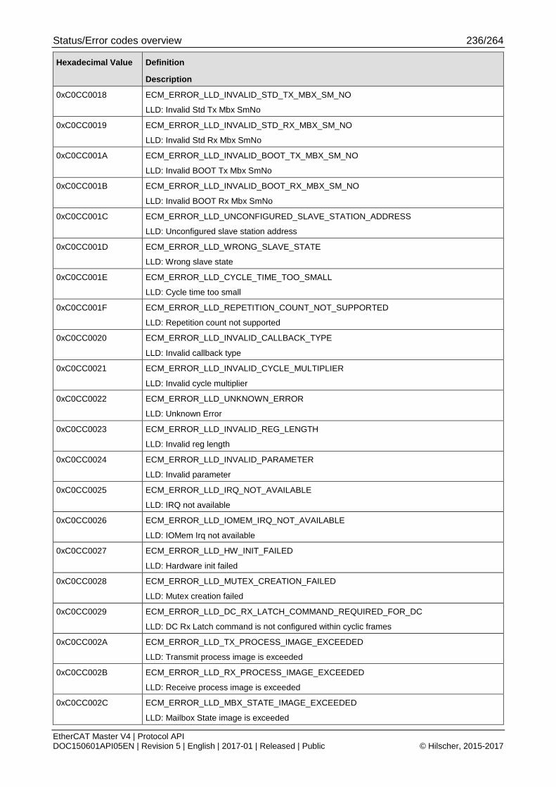
Status/Error codes overview 236/264
EtherCAT Master V4 | Protocol API DOC150601API05EN | Revision 5 | English | 2017-01 | Released | Public © Hilscher, 2015-2017
Hexadecimal Value Definition
Description
0xC0CC0018 ECM_ERROR_LLD_INVALID_STD_TX_MBX_SM_NO
LLD: Invalid Std Tx Mbx SmNo
0xC0CC0019 ECM_ERROR_LLD_INVALID_STD_RX_MBX_SM_NO
LLD: Invalid Std Rx Mbx SmNo
0xC0CC001A ECM_ERROR_LLD_INVALID_BOOT_TX_MBX_SM_NO
LLD: Invalid BOOT Tx Mbx SmNo
0xC0CC001B ECM_ERROR_LLD_INVALID_BOOT_RX_MBX_SM_NO
LLD: Invalid BOOT Rx Mbx SmNo
0xC0CC001C ECM_ERROR_LLD_UNCONFIGURED_SLAVE_STATION_ADDRESS
LLD: Unconfigured slave station address
0xC0CC001D ECM_ERROR_LLD_WRONG_SLAVE_STATE
LLD: Wrong slave state
0xC0CC001E ECM_ERROR_LLD_CYCLE_TIME_TOO_SMALL
LLD: Cycle time too small
0xC0CC001F ECM_ERROR_LLD_REPETITION_COUNT_NOT_SUPPORTED
LLD: Repetition count not supported
0xC0CC0020 ECM_ERROR_LLD_INVALID_CALLBACK_TYPE
LLD: Invalid callback type
0xC0CC0021 ECM_ERROR_LLD_INVALID_CYCLE_MULTIPLIER
LLD: Invalid cycle multiplier
0xC0CC0022 ECM_ERROR_LLD_UNKNOWN_ERROR
LLD: Unknown Error
0xC0CC0023 ECM_ERROR_LLD_INVALID_REG_LENGTH
LLD: Invalid reg length
0xC0CC0024 ECM_ERROR_LLD_INVALID_PARAMETER
LLD: Invalid parameter
0xC0CC0025 ECM_ERROR_LLD_IRQ_NOT_AVAILABLE
LLD: IRQ not available
0xC0CC0026 ECM_ERROR_LLD_IOMEM_IRQ_NOT_AVAILABLE
LLD: IOMem Irq not available
0xC0CC0027 ECM_ERROR_LLD_HW_INIT_FAILED
LLD: Hardware init failed
0xC0CC0028 ECM_ERROR_LLD_MUTEX_CREATION_FAILED
LLD: Mutex creation failed
0xC0CC0029 ECM_ERROR_LLD_DC_RX_LATCH_COMMAND_REQUIRED_FOR_DC
LLD: DC Rx Latch command is not configured within cyclic frames
0xC0CC002A ECM_ERROR_LLD_TX_PROCESS_IMAGE_EXCEEDED
LLD: Transmit process image is exceeded
0xC0CC002B ECM_ERROR_LLD_RX_PROCESS_IMAGE_EXCEEDED
LLD: Receive process image is exceeded
0xC0CC002C ECM_ERROR_LLD_MBX_STATE_IMAGE_EXCEEDED
LLD: Mailbox State image is exceeded
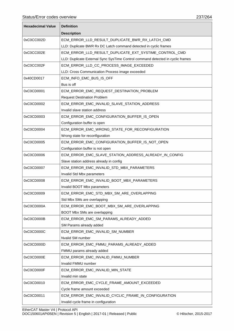
Status/Error codes overview 237/264
EtherCAT Master V4 | Protocol API DOC150601API05EN | Revision 5 | English | 2017-01 | Released | Public © Hilscher, 2015-2017
Hexadecimal Value Definition
Description
0xC0CC002D ECM_ERROR_LLD_RESULT_DUPLICATE_BWR_RX_LATCH_CMD
LLD: Duplicate BWR Rx DC Latch command detected in cyclic frames
0xC0CC002E ECM_ERROR_LLD_RESULT_DUPLICATE_EXT_SYSTIME_CONTROL_CMD
LLD: Duplicate External Sync SysTime Control command detected in cyclic frames
0xC0CC002F ECM_ERROR_LLD_CC_PROCESS_IMAGE_EXCEEDED
LLD: Cross Communication Process image exceeded
0x40CD0017 ECM_INFO_EMC_BUS_IS_OFF
Bus is off
0xC0CD0001 ECM_ERROR_EMC_REQUEST_DESTINATION_PROBLEM
Request Destination Problem
0xC0CD0002 ECM_ERROR_EMC_INVALID_SLAVE_STATION_ADDRESS
Invalid slave station address
0xC0CD0003 ECM_ERROR_EMC_CONFIGURATION_BUFFER_IS_OPEN
Configuration buffer is open
0xC0CD0004 ECM_ERROR_EMC_WRONG_STATE_FOR_RECONFIGURATION
Wrong state for reconfiguration
0xC0CD0005 ECM_ERROR_EMC_CONFIGURATION_BUFFER_IS_NOT_OPEN
Configuration buffer is not open
0xC0CD0006 ECM_ERROR_EMC_SLAVE_STATION_ADDRESS_ALREADY_IN_CONFIG
Slave station address already in config
0xC0CD0007 ECM_ERROR_EMC_INVALID_STD_MBX_PARAMETERS
Invalid Std Mbx parameters
0xC0CD0008 ECM_ERROR_EMC_INVALID_BOOT_MBX_PARAMETERS
Invalid BOOT Mbx parameters
0xC0CD0009 ECM_ERROR_EMC_STD_MBX_SM_ARE_OVERLAPPING
Std Mbx SMs are overlapping
0xC0CD000A ECM_ERROR_EMC_BOOT_MBX_SM_ARE_OVERLAPPING
BOOT Mbx SMs are overlapping
0xC0CD000B ECM_ERROR_EMC_SM_PARAMS_ALREADY_ADDED
SM Params already added
0xC0CD000C ECM_ERROR_EMC_INVALID_SM_NUMBER
Nvalid SM number
0xC0CD000D ECM_ERROR_EMC_FMMU_PARAMS_ALREADY_ADDED
FMMU params already added
0xC0CD000E ECM_ERROR_EMC_INVALID_FMMU_NUMBER
Invalid FMMU number
0xC0CD000F ECM_ERROR_EMC_INVALID_MIN_STATE
Invalid min state
0xC0CD0010 ECM_ERROR_EMC_CYCLE_FRAME_AMOUNT_EXCEEDED
Cycle frame amount exceeded
0xC0CD0011 ECM_ERROR_EMC_INVALID_CYCLIC_FRAME_IN_CONFIGURATION
Invalid cycle frame in configuration

Status/Error codes overview 238/264
EtherCAT Master V4 | Protocol API DOC150601API05EN | Revision 5 | English | 2017-01 | Released | Public © Hilscher, 2015-2017
Hexadecimal Value Definition
Description
0xC0CD0012 ECM_ERROR_EMC_CYCLE_FRAME_INDEX_NOT_VALID
Cycle frame index not valid
0xC0CD0013 ECM_ERROR_EMC_INVALID_TELEGRAM_LENGTH
Invalid telegram length
0xC0CD0014 ECM_ERROR_EMC_CYCLE_FRAME_LENGTH_EXCEEDED
Cycle frame length exceeded
0xC0CD0015 ECM_ERROR_EMC_AMOUNT_OF_TELEGRAMS_IN_CYCLIC_FRAME_EXCEEDED
Amount of telegrams in cyclic frame exceeded
0xC0CD0016 ECM_ERROR_EMC_STATE_CHANGE_IN_PROGRESS
State change in progress
0xC0CD0018 ECM_ERROR_EMC_TOO_MANY_SLAVES_GIVEN
Too many slaves given
0xC0CD0019 ECM_ERROR_EMC_DUPLICATE_STATION_ADDRESS_IN_LIST
Duplicate station address in list
0xC0CD001A ECM_ERROR_EMC_COMMAND_TYPE_NOT_ALLOWED_FOR_SLAVE_FSM
Command type not allowed for slave FSM
0xC0CD001B ECM_ERROR_EMC_CONFIGURATION_DATA_INCORRECT
Configuration data incorrect
0xC0CD001C ECM_ERROR_EMC_VENDORID_MISMATCH
VendorID mismatch
0xC0CD001D ECM_ERROR_EMC_PRODUCTCODE_MISMATCH
ProductCode mismatch
0xC0CD001E ECM_ERROR_EMC_REVISIONNO_MISMATCH
Revision number mismatch
0xC0CD001F ECM_ERROR_EMC_SERIALNO_MISMATCH
Serial number mismatch
0xC0CD0020 ECM_ERROR_EMC_LOST_CONNECTION
Lost connection
0xC0CD0021 ECM_ERROR_EMC_UNKNOWN_STATE_CHANGE_HAPPENED
Unknown state change happened
0xC0CD0022 ECM_ERROR_EMC_UNEXPECTED_STATE_CHANGE_HAPPENED
Unexpected state change happened
0xC0CD0023 ECM_ERROR_EMC_SLAVE_CHANGED_STATE
Slave changed state
0xC0CD0026 ECM_ERROR_EMC_DC_RX_TIMESTAMP_ERROR
DC Rx Timestamp error
0xC0CD0027 ECM_ERROR_EMC_DC_MASTER_PORT_TIMESTAMP_ERROR
DC Master Port Timestamp error
0xC0CD0028 ECM_ERROR_EMC_INVALID_SLAVE_INDEX
Invalid slave index
0xC0CD0029 ECM_ERROR_EMC_WRONG_MASTER_STATE

Status/Error codes overview 239/264
EtherCAT Master V4 | Protocol API DOC150601API05EN | Revision 5 | English | 2017-01 | Released | Public © Hilscher, 2015-2017
Hexadecimal Value Definition
Description
0xC0CD002A ECM_ERROR_EMC_INVALID_TRANSFER_ID
Invalid Transfer Id
0xC0CD002B ECM_ERROR_EMC_INVALID_SEGMENTATION
Invalid Segmentation
0xC0CD002C ECM_ERROR_EMC_IP_PARAMS_ALREADY_ADDED
EoE IP Params already added
0xC0CD002D ECM_ERROR_EMC_EOE_SUPPORT_NOT_AVAILABLE
EoE support not available
0xC0CD002E ECM_ERROR_EMC_END_CONFIGURATION_IN_PROGRESS
End configuration in progress
0xC0CD002F ECM_ERROR_EMC_WRONG_STATE_FOR_RECONFIGURATION_BUS_IS_ON
Wrong state for reconfiguration (Bus Is On)
0xC0CD0030 ECM_ERROR_EMC_WRONG_STATE_FOR_RECONFIGURATION_BUS_SCAN_ACTIVE
Wrong state for reconfiguration (Bus Scan Active)
0xC0CD0031 ECM_ERROR_EMC_WRONG_STATE_FOR_RECONFIGURATION_IN_PROGRESS_TO_BUSOFF
Wrong state for reconfiguration (In Progress to Bus off)
0xC0CD0032 ECM_EROR_EMC_NO_DIAG_ENTRY_AVAILABLE
No Diag Entry available
0xC0CD0033 ECM_ERROR_EMC_SLAVE_SYNC_PARAMS_NOT_POSSIBLE_WITHOUT_WORKING_DC
A slave has been configured to have SYNC0 and/or SYNC1 but does not support DC at all.
0xC0CD0034 ECM_ERROR_EMC_MANDATORY_SLAVE_MISSING
At least one required slave for boot up is missing.
0xC0CD0035 ECM_ERROR_EMC_WRONG_SLAVE_AT_POSITION
A wrong slave at a specific position has been detected.
0xC0CD0036 ECM_ERROR_EMC_NO_DC_REF_CLOCK
No DC reference clock
0xC0CD0037 ECM_ERROR_EMC_DC_REF_CLOCK_DOES_NOT_PROVIDE_64BIT
DC Reference clock does not provide 64 Bit
0xC0CD0038 ECM_ERROR_EMC_INVALID_DC_REF_CLOCK
Invalid DC Reference clock
0xC0CD0039 ECM_ERROR_EMC_COE_SUPPORT_NOT_AVAILABLE
CoE support not available
0xC0CD003A ECM_ERROR_EMC_SOE_SUPPORT_NOT_AVAILABLE
SoE support not available
0xC0CD003B ECM_ERROR_EMC_FOE_SUPPORT_NOT_AVAILABLE
FoE support not available
0xC0CD003C ECM_ERROR_EMC_AOE_SUPPORT_NOT_AVAILABLE
AoE support not available
0x40CD003E ECM_INFO_EMC_RECONNECTED
Reconnected

Status/Error codes overview 240/264
EtherCAT Master V4 | Protocol API DOC150601API05EN | Revision 5 | English | 2017-01 | Released | Public © Hilscher, 2015-2017
Hexadecimal Value Definition
Description
0x80CD003F ECM_WARN_EMC_DC_STOPPED
DC stopped
0xC0CD0040 ECM_ERROR_EMC_STOPPED_DUE_SYNC_ERROR
Stopped due Sync Error
0xC0CD0041 ECM_ERROR_EMC_MANDATORY_SLAVE_NOT_IN_OP
At least one mandatory slave is not in OP
0xC0CD0042 ECM_ERROR_EMC_BUS_CYCLE_TIME_NOT_POSSIBLE
Bus Cycle Time not possible
0xC0CD0043 ECM_ERROR_EMC_TOPOLOGY_ERROR_DETECTED
Topology error detected
0xC0CD0044 ECM_ERROR_EMC_TOPOLOGY_MISMATCH_DETECTED
Topology mismatch detected
0xC0CD0045 ECM_ERROR_EMC_NO_VALID_TOPOLOGY_CONFIGURATION_DATA
No valid topology configuration data
0xC0CD0046 ECM_ERROR_EMC_UNEXPECTED_SLAVE_AT_PORT0
Unexpected slave at port 0 of slave.
0xC0CD0047 ECM_ERROR_EMC_UNEXPECTED_SLAVE_AT_PORT1
Unexpected slave at port 1 of slave.
0xC0CD0048 ECM_ERROR_EMC_UNEXPECTED_SLAVE_AT_PORT2
Unexpected slave at port 2 of slave.
0xC0CD0049 ECM_ERROR_EMC_UNEXPECTED_SLAVE_AT_PORT3
Unexpected slave at port 3 of slave.
0xC0CD004A ECM_ERROR_EMC_UNEXPECTED_SLAVE_RECONNECTED
0xC0CD004B ECM_ERROR_EMC_UNEXPECTED_MISSING_SLAVE_AT_PORT0
Missing slave at port 0 of slave.
0xC0CD004C ECM_ERROR_EMC_UNEXPECTED_MISSING_SLAVE_AT_PORT1
Missing slave at port 1 of slave.
0xC0CD004D ECM_ERROR_EMC_UNEXPECTED_MISSING_SLAVE_AT_PORT2
Missing slave at port 2 of slave.
0xC0CD004E ECM_ERROR_EMC_UNEXPECTED_MISSING_SLAVE_AT_PORT3
Missing slave at port 3 of slave.
0xC0CD004F ECM_ERROR_EMC_SLAVE_NOT_CHECKED
Slave is not checked.
0xC0CD0050 ECM_ERROR_EMC_UNEXPECTED_SLAVE_AT_PORT0_1
Unexpected slave at port 0 and 1 of slave.
0xC0CD0051 ECM_ERROR_EMC_UNEXPECTED_SLAVE_AT_PORT0_2
Unexpected slave at port 0 and 2 of slave.
0xC0CD0052 ECM_ERROR_EMC_UNEXPECTED_SLAVE_AT_PORT0_3
Unexpected slave at port 0 and 3 of slave.
0xC0CD0053 ECM_ERROR_EMC_UNEXPECTED_SLAVE_AT_PORT1_2
Unexpected slave at port 1 and 2 of slave.

Status/Error codes overview 241/264
EtherCAT Master V4 | Protocol API DOC150601API05EN | Revision 5 | English | 2017-01 | Released | Public © Hilscher, 2015-2017
Hexadecimal Value Definition
Description
0xC0CD0054 ECM_ERROR_EMC_UNEXPECTED_SLAVE_AT_PORT1_3
Unexpected slave at port 1 and 3 of slave.
0xC0CD0055 ECM_ERROR_EMC_UNEXPECTED_SLAVE_AT_PORT2_3
Unexpected slave at port 2 and 3 of slave.
0xC0CD0056 ECM_ERROR_EMC_UNEXPECTED_SLAVE_AT_PORT0_1_2
Unexpected slave at port 0, 1 and 2 of slave.
0xC0CD0057 ECM_ERROR_EMC_UNEXPECTED_SLAVE_AT_PORT0_1_3
Unexpected slave at port 0, 1 and 3 of slave.
0xC0CD0058 ECM_ERROR_EMC_UNEXPECTED_SLAVE_AT_PORT0_2_3
Unexpected slave at port 0, 2 and 3 of slave.
0xC0CD0059 ECM_ERROR_EMC_UNEXPECTED_SLAVE_AT_PORT1_2_3
Unexpected slave at port 1, 2 and 3 of slave.
0xC0CD005A ECM_ERROR_EMC_MISSING_SLAVE_AT_PORT0_1
Missing slave at port 0 and 1 of slave.
0xC0CD005B ECM_ERROR_EMC_MISSING_SLAVE_AT_PORT0_2
Missing slave at port 0 and 2 of slave.
0xC0CD005C ECM_ERROR_EMC_MISSING_SLAVE_AT_PORT0_3
Missing slave at port 0 and 3 of slave.
0xC0CD005D ECM_ERROR_EMC_MISSING_SLAVE_AT_PORT1_2
Missing slave at port 1 and 2 of slave.
0xC0CD005E ECM_ERROR_EMC_MISSING_SLAVE_AT_PORT1_3
Missing slave at port 1 and 3 of slave.
0xC0CD005F ECM_ERROR_EMC_MISSING_SLAVE_AT_PORT2_3
Missing slave at port 2 and 3 of slave.
0xC0CD0060 ECM_ERROR_EMC_MISSING_SLAVE_AT_PORT0_1_2
Missing slave at port 0, 1 and 2 of slave.
0xC0CD0061 ECM_ERROR_EMC_MISSING_SLAVE_AT_PORT0_1_3
Missing slave at port 0, 1 and 3 of slave.
0xC0CD0062 ECM_ERROR_EMC_MISSING_SLAVE_AT_PORT0_2_3
Missing slave at port 0, 2 and 3 of slave.
0xC0CD0063 ECM_ERROR_EMC_MISSING_SLAVE_AT_PORT1_2_3
Missing slave at port 1, 2 and 3 of slave.
0xC0CD0065 ECM_ERROR_EMC_HC_PARTICIPANT_NOT_ALLOWED_IN_MANDATORY_SLAVE_LIST
A Hot Connect group participant is not allowed to be configured a mandatory slave
0xC0CD0066 ECM_ERROR_EMC_HC_PARTICIPANT_NOT_ALLOWED_IN_MULTIPLE_HC_GROUPS
A Hot Connect group participant is not allowed to be configured in multiple Hot Connect groups
0xC0CD0067 ECM_ERROR_EMC_GC_GROUP_HEAD_IS_NOT_LISTED_FOR_HC_DETECTION
Hot Connect group head is not listed for Hot Connect detection
0xC0CD0068 ECM_ERROR_EMC_DC_SETUP_CALCULATION_ERROR
DC Setup calculation has encountered an error
0xC0CD0069 ECM_ERROR_EMC_NON_DC_SLAVE_MORE_THAN_2_PORTS_IN_DC_SETUP
A slave, which does not support DC, has more than 2 ports in a DC setup

Status/Error codes overview 242/264
EtherCAT Master V4 | Protocol API DOC150601API05EN | Revision 5 | English | 2017-01 | Released | Public © Hilscher, 2015-2017
Hexadecimal Value Definition
Description
0xC0CD006A ECM_ERROR_EMC_HC_GROUP_CONTAINS_NOT_CONFIGURED_SLAVE
A Hot Connect group has been defined to include a slave address that has no configuration
0xC0CD006B ECM_ERROR_EMC_ALCONTROL_TIMEOUT
AL Control Timeout happened i.e. a slave ESM state change was not completed in time
0xC0CD006C ECM_ERROR_EMC_DC_MEASUREMENT_ERROR
DC measurement encountered an error
0xC0CD006D ECM_ERROR_EMC_RX_DESTINATION_EXCEEDS_RX_IMAGE_SIZE
Receive destination exceeds receive image size
0xC0CD006E ECM_ERROR_EMC_TX_SOURCE_EXCEEDS_TX_IMAGE_SIZE
Transmit source exceeds transmit image size
0xC0CD006F ECM_ERROR_EMC_WCSTATEBIT_EXCEEDS_RX_IMAGE_SIZE
WcState bit placement exceeds receive image size
0xC0CD0070 ECM_ERROR_EMC_WKC_MAPPING_EXCEEDS_RX_IMAGE_SIZE
Wkc value placement exceeds receive image size
0xC0CD0071 ECM_ERROR_EMC_DC_RX_LATCH_ERROR_AT_PORT0
DC Latch Error detected at port 0 of slave
0xC0CD0072 ECM_ERROR_EMC_DC_RX_LATCH_ERROR_AT_PORT1
DC Latch Error detected at port 1 of slave
0xC0CD0073 ECM_ERROR_EMC_DC_RX_LATCH_ERROR_AT_PORT2
DC Latch Error detected at port 2 of slave
0xC0CD0074 ECM_ERROR_EMC_DC_RX_LATCH_ERROR_AT_PORT3
DC Latch Error detected at port 3 of slave
0xC0CD0075 ECM_ERROR_EMC_DC_RX_LATCH_ERROR_AT_PORT0_1
DC Latch Error detected at ports 0 and 1 of slave
0xC0CD0076 ECM_ERROR_EMC_DC_RX_LATCH_ERROR_AT_PORT0_2
DC Latch Error detected at ports 0 and 2 of slave
0xC0CD0077 ECM_ERROR_EMC_DC_RX_LATCH_ERROR_AT_PORT0_3
DC Latch Error detected at ports 0 and 3 of slave
0xC0CD0078 ECM_ERROR_EMC_DC_RX_LATCH_ERROR_AT_PORT1_2
DC Latch Error detected at ports 1 and 2 of slave
0xC0CD0079 ECM_ERROR_EMC_DC_RX_LATCH_ERROR_AT_PORT1_3
DC Latch Error detected at ports 1 and 3 of slave
0xC0CD007A ECM_ERROR_EMC_DC_RX_LATCH_ERROR_AT_PORT2_3
DC Latch Error detected at ports 2 and 3 of slave
0xC0CD007B ECM_ERROR_EMC_DC_RX_LATCH_ERROR_AT_PORT0_1_2
DC Latch Error detected at ports 0, 1 and 2 of slave
0xC0CD007C ECM_ERROR_EMC_DC_RX_LATCH_ERROR_AT_PORT0_1_3
DC Latch Error detected at ports 0, 1 and 3 of slave
0xC0CD007D ECM_ERROR_EMC_DC_RX_LATCH_ERROR_AT_PORTS0_2_3
DC Latch Error detected at ports 0, 2 and 3 of slave
0xC0CD007E ECM_ERROR_EMC_DC_RX_LATCH_ERROR_AT_PORTS1_2_3
DC Latch Error detected at ports 1, 2 and 3 of slave

Status/Error codes overview 243/264
EtherCAT Master V4 | Protocol API DOC150601API05EN | Revision 5 | English | 2017-01 | Released | Public © Hilscher, 2015-2017
Hexadecimal Value Definition
Description
0xC0CD007F ECM_ERROR_EMC_DC_RX_LATCH_ERROR_AT_PORTS0_1_2_3
DC Latch Error detected at ports 0, 1, 2 and 3 of slave
0xC0CD0080 ECM_ERROR_EMC_ASSIGN_PDO_IS_MISSING_PDO_MAPPING
AssignPDO data is missing related PDO mapping data
0xC0CD0081 ECM_ERROR_EMC_EXT_SYNC_OBJ_IS_NOT_MAPPED_TO_SAME_SM
Parts of Ext Sync object are not mapped to the same SyncManager
0xC0CD0082 ECM_ERROR_EMC_DUPLICATE_EXT_SYNC_OBJ
Duplicate Ext Sync object mapping
0xC0CD0083 ECM_ERROR_EMC_UNSUPPORTED_EXT_SYNC_OBJ_RECORD
Unsupported Ext Sync object record detected
0xC0CD0084 ECM_ERROR_EMC_UNSUPPORTED_MAPPING_OF_EXT_SYNC_OBJ_RECORD
Unsupported mapping of Ext Sync object record detected
0xC0CD0085 ECM_ERROR_EMC_MISSING_MAPPING_OF_EXT_SYNC_OBJ_RECORD
Missing mapping of Ext Sync object record detected
0xC0CD0086 ECM_ERROR_EMC_EXT_SYNC_OBJ_IS_NOT_MAPPED_TO_SAME_FMMU
Parts of Ext Sync object are not mapped to the same FMMU
0xC0CD0087 ECM_ERROR_EMC_EXT_SYNC_OBJ_INTERNAL_ERROR
Internal error detected regarding Ext Sync object
0xC0CD0088 ECM_ERROR_EMC_EXT_SYNC_OBJ_IS_NOT_MAPPED_IN_ONE_CYCLIC_CMD
Parts of Ext Sync object are not mapped within the same cyclic command
0xC0CD0089 ECM_ERROR_EMC_UNSUPPORTED_FMMU_MAPPING_OF_EXT_SYNC_OBJ_RECORD
Unsupported FMMU mapping of Ext Sync object detected
0xC0CD008A ECM_ERROR_EMC_EXT_SYNC_REQUIRES_ADJUST_EXT_SYNC_CMD
Unicast Ext Sync control (APWR/FPWR 0x910) is required
0xC0CD008B ECM_ERROR_EMC_EXT_SYNC_CMD_DOES_NOT_MATCH_XRMW_CMD
Unicast Ext Sync control does not match xRMW command
0xC0CD008C ECM_ERROR_EMC_EXT_SYNC_REQUIRES_XRMW_CMD
Ext Sync requires DC configuration (xRMW command to 0x910)
0xC0CD008D ECM_ERROR_EMC_EXPLICIT_DEV_IDENT_FAILED_ALSTATUS
Explicit Device identification via ALSTATUS failed
0xC0CD008E ECM_ERROR_EMC_EXPLICIT_DEV_IDENT_FAILED_REG
Explicit Device identification via register failed
0xC0CD008F ECM_ERROR_EMC_COPY_INFOS_FOUND_AT_UNMAPPED_RECEIVE_DATA
CopyInfos found at unmapped receive data
0xC0CD0090 ECM_ERROR_EMC_COPY_INFO_RECEIVE_DATA_AREA_NOT_MATCHING
CopyInfo receive data area is not matching
0xC0CD0091 ECM_ERROR_EMC_SDO_UPLOAD_TOO_LONG
SDO Upload data too long
0xC0CD0092 ECM_ERROR_EMC_SDO_UPLOAD_TOO_SHORT
SDO Upload data too short
0xC0CD0093 ECM_ERROR_EMC_SDO_UPLOAD_COMPARE_DOES_NOT_MATCH_EXPECTATION
SDO Upload compare does not match expectation

Status/Error codes overview 244/264
EtherCAT Master V4 | Protocol API DOC150601API05EN | Revision 5 | English | 2017-01 | Released | Public © Hilscher, 2015-2017
Hexadecimal Value Definition
Description
0xC0CD0094 ECM_ERROR_EMC_SOE_READ_TOO_LONG
SoE Read IDN data too long
0xC0CD0095 ECM_ERROR_EMC_SOE_READ_TOO_SHORT
SoE Read IDN data too short
0xC0CD0096 ECM_ERROR_EMC_SOE_READ_COMPARE_DOES_NOT_MATCH_EXPECTATION
SoE Read compare does not match expectation
0xC0CD0097 ECM_ERROR_EMC_REG_INITCMD_COMPARE_DOES_NOT_MATCH_EXPECTATION
Register read compare does not match expectation
0xC0CD0098 ECM_ERROR_EMC_REDUNDANCY_PORT_ONLY_POSSIBLE_ONCE
Redundancy port can only be placed once into configuration
0xC0CD0099 ECM_ERROR_EMC_STARTUP_SCAN_SII_FAILED
Startup scan of SII failed
0xC0CD009A ECM_ERROR_EMC_STARTUP_VERIFY_SII_FAILED
Startup verification of SII failed
0xC0CD009B ECM_ERROR_EMC_MAIN_PORT_NOT_CONNECTED
Main port not connected during topology scan
0xC0CD009C ECM_ERROR_EMC_BUS_SCAN_TOO_MANY_SLAVES
Bus scan detects too many slaves
0xC0CD009D ECM_ERROR_EMC_BUS_SCAN_SPLIT_RING_NOT_SUPPORTED
Bus Scan detects unsupported split ring topology
0xC0CD009E ECM_ERROR_EMC_BUS_SHUTDOWN
Bus is shutting down
0xC0CD009F ECM_ERROR_EMC_MASTER_ADDRESS_NOT_ALLOWED_AS_STATION_ADDRESS
Master address (0) is not allowed as station address
0xC0CD00A0 ECM_ERROR_EMC_FIRST_STATION_HAS_INVALID_PORT_0
First station has invalid port 0
0xC0CD00A1 ECM_ERROR_EMC_STATION_HAS_INVALID_PORT
Station has invalid port
0xC0CD00A2 ECM_ERROR_EMC_STATION_HAS_NOT_LISTED_STATION_ADDRESS_IN_PORT
Station has not listed station address in port
0xC0CD00A3 ECM_ERROR_EMC_PORT_CONNECTION_BETWEEN_STATIONS_DOES_NOT_MATCH
Port connection between stations does not match
0xC0CD00A4 ECM_ERROR_EMC_STATION_HAS_ALREADY_USED_STATION_ADDRESS_IN_PORT
Station has already used station address in port
0xC0CD00A5 ECM_ERROR_EMC_INVALID_SM_PHYS_START_ADDRESS
Invalid Sm physical start address
0xC0CD00A6 ECM_ERROR_EMC_DC_TOPOLOGY_ON_REDUNDANCY_PORT_NOT_SUPPORTED
DC topology on redundancy port connection not supported.
DC slaves having AutoIncrement positions behind redundancy port
0xC0CD00A7 ECM_ERROR_EMC_SM_ASSIGN_PDO_ALREADY_ADDED
Sm AssignPdo already added

Status/Error codes overview 245/264
EtherCAT Master V4 | Protocol API DOC150601API05EN | Revision 5 | English | 2017-01 | Released | Public © Hilscher, 2015-2017
Hexadecimal Value Definition
Description
0xC0CD00A8 ECM_ERROR_EMC_BASE_SYNC_OFFSET_PERCENTAGE_OUT_OF_RANGE
Base Sync Offset percentage out of range
0xC0CF0001 ECM_ERROR_COE_INITIALIZATION_ERROR
CoE: Initialization Error
0xC0CF0002 ECM_ERROR_COE_INVALID_TRANSFER_HANDLE
CoE: Invalid transfer handle used
0xC0CF0003 ECM_ERROR_COE_NO_MAILBOX_AVAILABLE
CoE. No mailbox available
0xC0CF0004 ECM_ERROR_COE_INVALID_TRANSFER_STATE
CoE: Invalid transfer state
0xC0CF0005 ECM_ERROR_COE_TRANSFER_SEGMENT_TOO_LONG
CoE: Transfer segment is too long
0xC0CF0006 ECM_ERROR_COE_SHUTTING_DOWN
CoE is shutting down.
0xC0CF0007 ECM_ERROR_COE_MAX_TOTAL_BYTES_SMALLER_THAN_ACTUAL_TOTAL_BYTES
CoE: Maximum total bytes is smaller than actual total bytes.
0xC0CF0008 ECM_ERROR_COE_MAILBOX_TRANSMIT_FAILED
CoE: Mailbox transmit failed
0xC0CF0009 ECM_ERROR_COE_TRANSFER_ABORTED
CoE: Transfer has been aborted.
0xC0CF000A ECM_ERROR_COE_SDOINFO_INITIALIZATION_ERROR
0xC0CF000B ECM_ERROR_COE_WRONG_SLAVE_STATE
CoE: Wrong slave state
0xC0CF000C ECM_ERROR_COE_PROTOCOL_ERROR
CoE Protocol Error
0xC0CF000D ECM_ERROR_COE_NO_AOE_AVAILABLE
CoE: No AoE available
0xC0CF000F ECM_ERROR_COE_INVALID_SLAVE_STATION_ADDRESS
CoE: Invalid slave station address
0xC0CF8000 ECM_ERROR_COE_ABORTCODE_TOGGLE_BIT_NOT_ALTERNATED
SDO Abort Code: Toggle Bit not alternated
0xC0CF8001 ECM_ERROR_COE_ABORTCODE_COMMAND_SPECIFIER_NOT_VALID
SDO Abort Code: Command specifier not valid
0xC0CF8002 ECM_ERROR_COE_ABORTCODE_PROTOCOL_TIMEOUT
SDO Abort Code: Protocol Timeout
0xC0CF8003 ECM_ERROR_COE_ABORTCODE_OUT_OF_MEMORY
SDO Abort Code: Out Of Memory
0xC0CF8004 ECM_ERROR_COE_ABORTCODE_UNSUPPORTED_ACCESS
SDO Abort Code: Unsupported access
0xC0CF8005 ECM_ERROR_COE_ABORTCODE_OBJECT_IS_WRITE_ONLY
SDO Abort Code: Object is write only

Status/Error codes overview 246/264
EtherCAT Master V4 | Protocol API DOC150601API05EN | Revision 5 | English | 2017-01 | Released | Public © Hilscher, 2015-2017
Hexadecimal Value Definition
Description
0xC0CF8006 ECM_ERROR_COE_ABORTCODE_OBJECT_IS_READ_ONLY
SDO Abort Code: Object is read only
0xC0CF8007 ECM_ERROR_COE_ABORTCODE_SUBINDEX_CANNOT_BE_WRITTEN_SI0_NZ
SDO Abort Code: Subindex cannot be written if subindex 0 is not zero
0xC0CF8008 ECM_ERROR_COE_ABORTCODE_COMPLETE_ACCESS_NOT_SUPPORTED
SDO Abort Code: Complete access not supported
0xC0CF8009 ECM_ERROR_COE_ABORTCODE_OBJECT_LENGTH_EXCEEDS_MAILBOX_SIZE
SDO Abort Code: Object length exceeds mailbox size
0xC0CF800A ECM_ERROR_COE_ABORTCODE_OBJECT_MAPPED_TO_RXPDO_NO_WRITE
SDO Abort Code: Object mapped to RxPDO, SDO Download blocked
0xC0CF800B ECM_ERROR_COE_ABORTCODE_OBJECT_DOES_NOT_EXIST
SDO Abort Code: Object does not exist
0xC0CF800C ECM_ERROR_COE_ABORTCODE_OBJECT_CANNOT_BE_PDO_MAPPED
SDO Abort Code: Object cannot be mapped to PDO
0xC0CF800D ECM_ERROR_COE_ABORTCODE_PDO_LENGTH_WOULD_EXCEED
SDO Abort Code: PDO Length would exceed maximum size
0xC0CF800E ECM_ERROR_COE_ABORTCODE_GEN_PARAM_INCOMPATIBILITY
SDO Abort Code: General parameter incompatibility
0xC0CF800F ECM_ERROR_COE_ABORTCODE_ACCESS_FAILED_DUE_TO_HW_ERROR
SDO Abort Code: Access failed due to hardware error
0xC0CF8010 ECM_ERROR_COE_ABORTCODE_DATATYPE_DOES_NOT_MATCH
SDO Abort Code: Data type does not match
0xC0CF8011 ECM_ERROR_COE_ABORTCODE_DATATYPE_LENGTH_TOO_LONG
SDO Abort Code: Data type length too long
0xC0CF8012 ECM_ERROR_COE_ABORTCODE_DATATYPE_LENGTH_TOO_SHORT
SDO Abort Code: Data type length too short
0xC0CF8013 ECM_ERROR_COE_ABORTCODE_SUBINDEX_DOES_NOT_EXIST
SDO Abort Code: Subindex does not exist
0xC0CF8014 ECM_ERROR_COE_ABORTCODE_RANGE_OF_PARAMETER_EXCEEDED
SDO Abort Code: Range of parameter exceeded
0xC0CF8015 ECM_ERROR_COE_ABORTCODE_VALUE_OF_PARAM_WRITTEN_TOO_HIGH
SDO Abort Code: Value of parameter written too high
0xC0CF8016 ECM_ERROR_COE_ABORTCODE_VALUE_OF_PARAM_WRITTEN_TOO_LOW
SDO Abort Code: Value of parameter written too low
0xC0CF8017 ECM_ERROR_COE_ABORTCODE_MIN_VALUE_IS_LESS_THAN_MAX_VALUE
SDO Abort Code: Minimum value is less than maximum value
0xC0CF8018 ECM_ERROR_COE_ABORTCODE_GENERAL_ERROR
SDO Abort Code: General Error
0xC0CF8019 ECM_ERROR_COE_ABORTCODE_NO_TRANSFER_TO_APP
SDO Abort Code: Data cannot be transferred or stored to the application

Status/Error codes overview 247/264
EtherCAT Master V4 | Protocol API DOC150601API05EN | Revision 5 | English | 2017-01 | Released | Public © Hilscher, 2015-2017
Hexadecimal Value Definition
Description
0xC0CF801A ECM_ERROR_COE_ABORTCODE_LOCAL_CONTROL
SDO Abort Code: Data cannot be transferred or stored to the application because of local control
0xC0CF801B ECM_ERROR_COE_ABORTCODE_NO_TRANSFER_DUE_TO_CURRENT_STATE
SDO Abort Code: Data cannot be transferred or stored to the applcation because of the present device state
0xC0CF801C ECM_ERROR_COE_ABORTCODE_NO_OBJECT_DICTIONARY_PRESENT
SDO Abort Code: Object dictionary dynamic generation fails or no object dictionary is present
0xC0CF801D ECM_ERROR_COE_ABORTCODE_UNKNOWN_ABORT_CODE
SDO Abort Code: Unknown abort code
0xC0CF801E ECM_ERROR_COE_ABORTCODE_GEN_INTERNAL_COMPAT
SDO Abort Code: General internal incompatibility in the device
0xC0D00001 ECM_ERROR_EOE_INVALID_MAC_ADDRESS
Invalid MAC address
0xC0D00002 ECM_ERROR_EOE_INVALID_CALLBACK_TYPE
Invalid callback type
0xC0D00003 ECM_ERROR_EOE_DESTINATION_UNREACHABLE
Destination unreachable
0xC0D00004 ECM_ERROR_EOE_INVALID_EOE_RESPONSE
Invalid EoE Response
0xC0D00005 ECM_ERROR_EOE_UNKNOWN_ERROR
SetIPParam/SetFilterParam: Unknown error
0xC0D00006 ECM_ERROR_EOE_UNSPECIFIED_ERROR
SetIPParam/SetFilterParam: Unspecified Error
0xC0D00007 ECM_ERROR_EOE_UNSUPPORTED_FRAME_TYPE
SetIPParam/SetFilterParam: Unsupported frame type
0xC0D00008 ECM_ERROR_EOE_NO_IP_SUPPORT
SetIPParam/SetFilterParam: No IP support
0xC0D00009 ECM_ERROR_EOE_DHCP_NOT_SUPPORTED
SetIPParam/SetFilterParam: DHCP not supported
0xC0D0000A ECM_ERROR_EOE_NO_FILTER_SUPPORT
SetIPParam/SetFilterParam: No filter supported
0xC0D0000B ECM_ERROR_EOE_TIMEOUT
EoE Timeout
0xC0D0000C ECM_ERROR_EOE_SHUTTING_DOWN
EoE is shutting down
0xC0D0000D ECM_ERROR_EOE_MASTER_ADDRESS_NOT_ALLOWED
EoE: Master address is not allowed to use here
0xC0D0000E ECM_ERROR_EOE_CONFIGURATION_IS_NOT_OPEN
EoE: Configuration is not open
0xC0D0000F ECM_ERROR_EOE_CONFIGURATION_IS_ALREADY_OPEN
EoE: Configuration is already open

Status/Error codes overview 248/264
EtherCAT Master V4 | Protocol API DOC150601API05EN | Revision 5 | English | 2017-01 | Released | Public © Hilscher, 2015-2017
Hexadecimal Value Definition
Description
0xC0D00010 ECM_ERROR_EOE_DUPLICATE_IP_ADDRESS
EoE: Duplicate IP address
0xC0D00011 ECM_ERROR_EOE_DUPLICATE_MAC_ADDRESS_ON_MULTIPLE_PORTS
EoE: Duplicate MAC address on multiple ports
0xC0D00012 ECM_ERROR_EOE_FRAME_TOO_LARGE
EoE: Frame too large
0xC0D00013 ECM_ERROR_EOE_IF_INITIALIZATION_ERROR
EoE: Interface initialization error
0xC0D00014 ECM_ERROR_EOE_IF_NO_FRAME_AVAILABLE
EoE: No Frame available
0xC0D00015 ECM_ERROR_EOE_LINK_DOWN
EoE: Link down
0xC0D10002 ECM_ERROR_FOE_ERROR_UNKNOWN_ERROR
0xC0D10003 ECM_ERROR_FOE_INVALID_TRANSFER_HANDLE
FoE: Invalid transfer handle
0xC0D10004 ECM_ERROR_FOE_INVALID_TRANSFER_STATE
FoE: Invalid transfer state
0xC0D10005 ECM_ERROR_FOE_INVALID_SLAVE_STATION_ADDRESS
FoE: Invalid slave station address
0xC0D10006 ECM_ERROR_FOE_WRONG_SLAVE_STATE
FoE: Wrong slave state
0xC0D10007 ECM_ERROR_FOE_NO_MAILBOX_AVAILABLE
FoE: No mailbox available
0xC0D10008 ECM_ERROR_FOE_TRANSFER_ABORTED
FoE: Transfer has been aborted
0xC0D10009 ECM_ERROR_FOE_PROTOCOL_TIMEOUT
FoE: Protocol Timeout
0xC0D1000A ECM_ERROR_FOE_TRANSFER_SEGMENT_TOO_LONG
FoE: Transfer segment is too long
0xC0D1000B ECM_ERROR_FOE_MAILBOX_TRANSMIT_FAILED
FoE: Mailbox transmit failed
0xC0D1000C ECM_ERROR_FOE_FILENAME_TOO_LONG
FoE: Filename is too long
0xC0D1000D ECM_ERROR_FOE_BUFFER_EXCEEDED
FoE: Buffer is exceeded
0xC0D1000E ECM_ERROR_FOE_FIRST_SEGMENT_SHOULD_NOT_BE_EMPTY
FoE: First segment should not be empty
0xC0D1000F ECM_ERROR_FOE_SEGMENT_SHOULD_BE_EMPTY
FoE: Segment should be empty
0xC0D18000 ECM_ERROR_FOE_ERROR_NOT_DEFINED
FoE: Error Response: not defined

Status/Error codes overview 249/264
EtherCAT Master V4 | Protocol API DOC150601API05EN | Revision 5 | English | 2017-01 | Released | Public © Hilscher, 2015-2017
Hexadecimal Value Definition
Description
0xC0D18001 ECM_ERROR_FOE_ERROR_NOT_FOUND
FoE: Error Response: Not Found
0xC0D18002 ECM_ERROR_FOE_ACCESS_DENIED
FoE: Error Response: Access Denied
0xC0D18003 ECM_ERROR_FOE_ERROR_DISK_FULL
FoE: Error Response: Disk full
0xC0D18004 ECM_ERROR_FOE_ERROR_ILLEGAL
FoE: Error Response: Illegal
0xC0D18005 ECM_ERROR_FOE_ERROR_PACKET_NUMBER_WRONG
FoE: Error Response: Packet number is wrong
0xC0D18006 ECM_ERROR_FOE_ERROR_ALREADY_EXISTS
FoE: Error Response: Already exists
0xC0D18007 ECM_ERROR_FOE_ERROR_NO_USER
FoE: Error Response: No User
0xC0D18008 ECM_ERROR_FOE_ERROR_BOOTSTRAP_ONLY
FoE: Acces to specified file is only allowed in BOOT state
0xC0D18009 ECM_ERROR_FOE_ERROR_NOT_BOOTSTRAP
FoE: Access to specified file is only allowed when in PREOP, SAFEOP or OP
0xC0D1800A ECM_ERROR_FOE_ERROR_NO_RIGHTS
FoE: No Rights
0xC0D1800B ECM_ERROR_FOE_ERROR_PROGRAM_ERROR
FoE: Program Error
0xC0D20001 ECM_ERROR_SOE_UNKNOWN_SOE_ERROR
SoE: Unknown SoE Error
0xC0D20002 ECM_ERROR_SOE_INITIALIZATION_ERROR
SoE: Initialization error
0xC0D20003 ECM_ERROR_SOE_INVALID_TRANSFER_HANDLE
SoE: Invalid transfer handle
0xC0D20004 ECM_ERROR_SOE_NO_MAILBOX_AVAILABLE
SoE: No Mailbox available
0xC0D20005 ECM_ERROR_SOE_INVALID_TRANSFER_STATE
SoE: Invalid transfer state
0xC0D20006 ECM_ERROR_SOE_TRANSFER_SEGMENT_TOO_LONG
SoE: Transfer segment is too long
0xC0D20007 ECM_ERROR_SOE_SHUTTING_DOWN
SoE is shutting down
0xC0D20008 ECM_ERROR_SOE_MAX_TOTAL_BYTES_SMALLER_THAN_ACTUAL_TOTAL_BYTES
SoE: Maximum total bytes is smaller than actual total bytes
0xC0D20009 ECM_ERROR_SOE_MAILBOX_TRANSMIT_FAILED
SoE: Mailbox transmit failed
0xC0D2000A ECM_ERROR_SOE_INVALID_SOE_HEADER
SoE: Invalid SoE header

Status/Error codes overview 250/264
EtherCAT Master V4 | Protocol API DOC150601API05EN | Revision 5 | English | 2017-01 | Released | Public © Hilscher, 2015-2017
Hexadecimal Value Definition
Description
0xC0D2000B ECM_ERROR_SOE_PROTOCOL_TIMEOUT
SoE: Protocol Timeout
0xC0D2000C ECM_ERROR_SOE_PROTOCOL_ERROR
SoE: Protocol Error
0xC0D2000D ECM_ERROR_SOE_TRANSFER_ABORTED
SoE: Transfer has been aborted
0xC0D2000E ECM_ERROR_SOE_WRONG_SLAVE_STATE
SoE: Wrong slave state
0xC0D2000F ECM_ERROR_SOE_NO_AOE_AVAILABLE
SoE: No AoE available
0xC0D20010 ECM_ERROR_SOE_INVALID_SLAVE_STATION_ADDRESS
SoE: Invalid slave station address
0xC0D21001 ECM_ERROR_SOE_SSC_NO_IDN
SoE: No IDN
0xC0D21009 ECM_ERROR_SOE_SSC_INVALID_ACCESS_TO_ELEMENT_1
SoE: Invalid access to element 1
0xC0D22001 ECM_ERROR_SOE_SCC_NO_NAME
SoE: IDN has no name
0xC0D22002 ECM_ERROR_SOE_SSC_NAME_TRANSMISSION_IS_TOO_SHORT
SoE: Name transmission is too short
0xC0D22003 ECM_ERROR_SOE_SSC_NAME_TRANSMISSION_IS_TOO_LONG
SoE: Name transmission is too long
0xC0D22004 ECM_ERROR_SOE_SSC_NAME_CANNOT_BE_CHANGED
SoE: Name cannot be changed
0xC0D22005 ECM_ERROR_SOE_SSC_NAME_IS_WRITE_PROTECTED_AT_THIS_TIME
SoE: Name is write protected at this time
0xC0D23002 ECM_ERROR_SOE_SSC_ATTRIBUTE_TRANSMISSION_IS_TOO_SHORT
SoE: Attribute transmission is too short
0xC0D23003 ECM_ERROR_SOE_SSC_ATTRIBUTE_TRANSMISSION_IS_TOO_LONG
SoE: Attribute transmission is too long
0xC0D23004 ECM_ERROR_SOE_SSC_ATTRIBUTE_CANNOT_BE_CHANGED
SoE: Attribute cannot be changed
0xC0D23005 ECM_ERROR_SOE_SSC_ATTRIBUTE_IS_WRITE_PROTECTED_AT_THIS_TIME
SoE: Attribute is write protected at this time
0xC0D24001 ECM_ERROR_SOE_SSC_NO_UNIT
SoE: IDN has no unit
0xC0D24002 ECM_ERROR_SOE_SSC_UNIT_TRANSMISSION_IS_TOO_SHORT
SoE: Unit transmission is too short
0xC0D24003 ECM_ERROR_SOE_SSC_UNIT_TRANSMISSION_IS_TOO_LONG
SoE: Unit transmission is too long
0xC0D24004 ECM_ERROR_SOE_SSC_UNIT_CANNOT_BE_CHANGED
SoE: Unit cannot be changed

Status/Error codes overview 251/264
EtherCAT Master V4 | Protocol API DOC150601API05EN | Revision 5 | English | 2017-01 | Released | Public © Hilscher, 2015-2017
Hexadecimal Value Definition
Description
0xC0D24005 ECM_ERROR_SOE_SSC_UNIT_IS_WRITE_PROTECTED_AT_THIS_TIME
SoE: Unit is write protected at this time
0xC0D25001 ECM_ERROR_SOE_SSC_NO_MAXIMUM_VALUE
SoE: IDN has no maximum value
0xC0D25002 ECM_ERROR_SOE_SSC_MINIMUM_VALUE_TRANSMISSION_IS_TOO_SHORT
SoE: Minimum value transmission is too short
0xC0D25003 ECM_ERROR_SOE_SSC_MINIMUM_VALUE_TRANSMISSION_IS_TOO_LONG
SoE: Minimum value transmission is too long
0xC0D25004 ECM_ERROR_SOE_SSC_MINIMUM_VALUE_CANNOT_BE_CHANGED
SoE: Minimum value cannot be changed
0xC0D25005 ECM_ERROR_SOE_SSC_MINIMUM_VALUE_IS_WRITE_PROTECTED_AT_THIS_TIME
SoE: Mimum value is write protected at this time
0xC0D26001 ECM_ERROR_SOE_SSC_NO_MAXIMUM_VALUE
SoE: IDN has no maximum value
0xC0D26002 ECM_ERROR_SOE_SSC_MAXIMUM_VALUE_TRANSMISSION_IS_TOO_SHORT
SoE: Maximum value transmission is too short
0xC0D26003 ECM_ERROR_SOE_SSC_MAXIMUM_VALUE_TRANSMISSION_IS_TOO_LONG
SoE: Maximum value transmission is too long
0xC0D26004 ECM_ERROR_SOE_SSC_MAXIMUM_VALUE_CANNOT_BE_CHANGED
SoE: Maximum value cannot be changed
0xC0D26005 ECM_ERROR_SOE_SSC_MAXIMUM_VALUE_IS_WRITE_PROTECTED_AT_THIS_TIME
SoE: Maximum value is write protected at this time
0xC0D27002 ECM_ERROR_SOE_SSC_OPDATA_TRANSMISSION_IS_TOO_SHORT
SoE: OpData transmission is too short
0xC0D27003 ECM_ERROR_SOE_SSC_OPDATA_TRANSMISSION_IS_TOO_LONG
SoE: OpData transmission is too long
0xC0D27004 ECM_ERROR_SOE_SSC_OPDATA_CANNOT_BE_CHANGED
SoE: OpData cannot be changed
0xC0D27005 ECM_ERROR_SOE_SSC_OPDATA_IS_WRITE_PROTECTED_AT_THIS_TIME
SoE: OpData is write protected at this time
0xC0D27006 ECM_ERROR_SOE_SSC_OPDATA_IS_LOWER_THAN_MINIMUM_VALUE
SoE: OpData is lower than minimum value
0xC0D27007 ECM_ERROR_SOE_SSC_OPDATA_IS_HIGHER_THAN_MAXIMUM_VALUE
SoE: OpData is higher than maximum value
0xC0D27008 ECM_ERROR_SOE_SSC_OPDATA_IS_INVALID
SoE: OpData is invalid
0xC0D27009 ECM_ERROR_SOE_SSC_OPDATA_IS_WRITE_PROTECTED_BY_PASSWORD
SoE: OpData is write protected by password
0xC0D2700A ECM_ERROR_SOE_SSC_OPDATA_IS_WRITE_PROTECTED_DUE_CYCLICALLY_CONFIGURED
SoE: OpData is write protected due to being cyclically configured

Status/Error codes overview 252/264
EtherCAT Master V4 | Protocol API DOC150601API05EN | Revision 5 | English | 2017-01 | Released | Public © Hilscher, 2015-2017
Hexadecimal Value Definition
Description
0xC0D2700B ECM_ERROR_SOE_SSC_OPDATA_INVALID_DIRECT_ADDRESSING
SoE: Invalid direct addressing
0xC0D2700C ECM_ERROR_SOE_SSC_OPDATA_IS_WRITE_PROTECTED_DUE_OTHER_SETTINGS
SoE: OpData is write protected due to other settings.
0xC0D2700D ECM_ERROR_SOE_SSC_OPDATA_INVALID_FLOATING_POINT_NUMBER
SoE: Invalid floating point number
0xC0D2700E ECM_ERROR_SOE_SSC_OPDATA_IS_WRITE_PROTECTED_AT_PARAMETERIZATION_LEVEL
SoE: OpData is write protected at parameterization level
0xC0D2700F ECM_ERROR_SOE_SSC_OPDATA_IS_WRITE_PROTECTED_AT_OPERATION_LEVEL
SoE: OpData is write protected at operation level
0xC0D27010 ECM_ERROR_SOE_SSC_OPDATA_PROCEDURE_COMMAND_ALREADY_ACTIVE
SoE: Procedure command already active
0xC0D27011 ECM_ERROR_SOE_SSC_OPDATA_PROCEDURE_COMMAND_NOT_INTERRUPTIBLE
SoE: Procedure command not interruptible
0xC0D27012 ECM_ERROR_SOE_SSC_OPDATA_PROCEDURE_COMMAND_NOT_EXECUTABLE_AT_THIS_TIME
SoE: Procedure command is not executable at this time
0xC0D27013 ECM_ERROR_SOE_SSC_OPDATA_PROCEDURE_COMMAND_NOT_EXECUTABLE_INVALID_PARAM
SoE: Procedure command is not executable due to invalid parameter
0xC0D4005C ECM_ERROR_ENI_NO_SLAVES_IN_ENI
ENI does not contain any slaves
0xC0D50001 ECM_ERROR_ALSTATCODE_UNSPECIFIED_ERROR
ALStatusCode: Unspecified error
0xC0D50002 ECM_ERROR_ALSTATCODE_NO_MEMORY
ALStatusCode: No memory
0xC0D50003 ECM_ERROR_ALSTATCODE_INVALID_DEVICE_SETUP
ALStatusCode: Invalid Device Setup
0xC0D50011 ECM_ERROR_ALSTATCODE_INVALID_REQUESTED_STATE_CHANGE
ALStatusCode: Invalid requested state change
0xC0D50012 ECM_ERROR_ALSTATCODE_UNKNOWN_REQUESTED_STATE
ALStatusCode: Unknown requested state
0xC0D50013 ECM_ERROR_ALSTATCODE_BOOTSTRAP_NOT_SUPPORTED
ALStatusCode: Bootstrap not supported
0xC0D50014 ECM_ERROR_ALSTATCODE_NO_VALID_FIRMWARE
ALStatusCode: No valid firmware
0xC0D50015 ECM_ERROR_ALSTATCODE_INVALID_BOOT_MAILBOX_CONFIGURATION
ALStatusCode: Invalid BOOT mailbox configuration
0xC0D50016 ECM_ERROR_ALSTATCODE_INVALID_PREOP_MAILBOX_CONFIGURATION
ALStatusCode: Invalid PREOP mailbox configuration

Status/Error codes overview 253/264
EtherCAT Master V4 | Protocol API DOC150601API05EN | Revision 5 | English | 2017-01 | Released | Public © Hilscher, 2015-2017
Hexadecimal Value Definition
Description
0xC0D50017 ECM_ERROR_ALSTATCODE_INVALID_SYNC_MANAGER_CONFIGURATION
ALStatusCode: Invalid sync manager configuration
0xC0D50018 ECM_ERROR_ALSTATCODE_NO_VALID_INPUTS_AVAILABLE
ALStatusCode: No valid inputs available
0xC0D50019 ECM_ERROR_ALSTATCODE_NO_VALID_OUTPUTS
ALStatusCode: No valid outputs
0xC0D5001A ECM_ERROR_ALSTATCODE_SYNCHRONIZATION_ERROR
ALStatusCode: Synchronization error
0xC0D5001B ECM_ERROR_ALSTATCODE_SYNC_MANAGER_WATCHDOG
ALStatusCode: Sync Manager watchdog
0xC0D5001C ECM_ERROR_ALSTATCODE_INVALID_SYNC_MANAGER_TYPES
ALStatusCode: Invalid Sync Manager Types
0xC0D5001D ECM_ERROR_ALSTATCODE_INVALID_OUTPUT_CONFIGURATION
ALStatusCode: Invalid output configuration
0xC0D5001E ECM_ERROR_ALSTATCODE_INVALID_INPUT_CONFIGURATION
ALStatusCode: Invalid input configuration
0xC0D5001F ECM_ERROR_ALSTATCODE_INVALID_WATCHDOG_CONFIGURATION
ALStatusCode: Invalid Watchdog configuration
0xC0D50020 ECM_ERROR_ALSTATCODE_SLAVE_NEEDS_COLD_START
ALStatusCode: Slave needs cold start
0xC0D50021 ECM_ERROR_ALSTATCODE_SLAVE_NEEDS_INIT
ALStatusCode: Slave needs INIT
0xC0D50022 ECM_ERROR_ALSTATCODE_SLAVE_NEEDS_PREOP
ALStatusCode: slave needs PREOP
0xC0D50023 ECM_ERROR_ALSTATCODE_SLAVE_NEEDS_SAFEOp
ALStatusCode: slave needs SAFEOP
0xC0D50024 ECM_ERROR_ALSTATCODE_INVALID_INPUT_MAPPING
ALStatusCode: Invalid Input Mapping
0xC0D50025 ECM_ERROR_ALSTATCODE_INVALID_OUTPUT_MAPPING
ALStatusCode: Invalid Output Mapping
0xC0D50026 ECM_ERROR_ALSTATCODE_INCONSISTENT_SETTINGS
ALStatusCode: Inconsistent settings
0xC0D50027 ECM_ERROR_ALSTATCODE_FREERUN_NOT_SUPPORTED
ALStatusCode: FreeRun not supported
0xC0D50028 ECM_ERROR_ALSTATCODE_SYNCMODE_NOT_SUPPORTED
ALStatusCode: SyncMode not supported
0xC0D50029 ECM_ERROR_ALSTATCODE_FREERUN_NEEDS_3BUFFER_MODE
ALStatusCode: FreeRun needs 3Buffer mode
0xC0D5002A ECM_ERROR_ALSTATCODE_BACKGROUND_WATCHDOG
ALStatusCode: Background Watchdog
0xC0D5002B ECM_ERROR_ALSTATCODE_NO_VALID_INPUTS_AND_OUTPUTS
ALStatusCode: No valid Inputs and Outputs

Status/Error codes overview 254/264
EtherCAT Master V4 | Protocol API DOC150601API05EN | Revision 5 | English | 2017-01 | Released | Public © Hilscher, 2015-2017
Hexadecimal Value Definition
Description
0xC0D5002C ECM_ERROR_ALSTATCODE_FATAL_SYNC_ERROR
ALStatusCode: Fatal Sync error
0xC0D5002D ECM_ERROR_ALSTATCODE_NO_SYNC_ERROR
ALStatusCode: No Sync error
0xC0D50030 ECM_ERROR_ALSTATCODE_INVALID_DC_SYNC_CONFIGURATION
ALStatusCode: Invalid DC SYNC configuration
0xC0D50031 ECM_ERROR_ALSTATCODE_INVALID_DC_LATCH_CONFIGURATION
ALStatusCode: Invalid DC Latch configuration
0xC0D50032 ECM_ERROR_ALSTATCODE_PLL_ERROR
ALStatusCode: PLL error
0xC0D50033 ECM_ERROR_ALSTATCODE_DC_SYNC_IO_ERROR
ALStatusCode: DC Sync IO error
0xC0D50034 ECM_ERROR_ALSTATCODE_DC_SYNC_TIMEOUT_ERROR
ALStatusCode: DC Sync Timeout Error
0xC0D50035 ECM_ERROR_ALSTATCODE_DC_INVALID_SYNC_CYCLE_TIME
ALStatusCode: DC Invalid Sync Cycle Time
0xC0D50036 ECM_ERROR_ALSTATCODE_DC_SYNC0_CYCLE_TIME
ALStatusCode: DC Sync0 Cycle Time
0xC0D50037 ECM_ERROR_ALSTATCODE_DC_SYNC1_CYCLE_TIME
ALStatusCode: DC Sync1 Cycle Time
0xC0D50041 ECM_ERROR_ALSTATCODE_MBX_AOE
ALStatusCode: MBX_AOE
0xC0D50042 ECM_ERROR_ALSTATCODE_MBX_EOE
ALStatusCode: MBX_EOE
0xC0D50043 ECM_ERROR_ALSTATCODE_MBX_COE
ALStatusCode: MBX_COE
0xC0D50044 ECM_ERROR_ALSTATCODE_MBX_FOE
ALStatusCode: MBX_FOE
0xC0D50045 ECM_ERROR_ALSTATCODE_MBX_SOE
ALStatusCode: MBX_SOE
0xC0D5004F ECM_ERROR_ALSTATCODE_MBX_VOE
ALStatusCode: MBX_VOE
0xC0D50050 ECM_ERROR_ALSTATCODE_EEPROM_NO_ACCESS
ALStatusCode: EEPROM no access
0xC0D50051 ECM_ERROR_ALSTATCODE_EEPROM_ERROR
ALStatusCode: EEPROM error
0xC0D50060 ECM_ERROR_ALSTATCODE_SLAVE_RESTARTED_LOCALLY
ALStatusCode: Slave restarted locally
0xC0D50061 ECM_ERROR_ALSTATCODE_DEVICE_IDENTIFICATION_VALUE_UPDATED
ALStatusCode: Device identificatin value updated
0xC0D500F0 ECM_ERROR_ALSTATCODE_APPLICATION_CONTROLLER_AVAILABLE
ALStatusCode: Application controller available

Status/Error codes overview 255/264
EtherCAT Master V4 | Protocol API DOC150601API05EN | Revision 5 | English | 2017-01 | Released | Public © Hilscher, 2015-2017
Hexadecimal Value Definition
Description
0xC0D58000 ECM_ERROR_ALSTATCODE_VENDOR_SPECIFIC_CODE_START
Begin of vendor-specific ALStatusCode mapping
0xC0D5FFFF ECM_ERROR_ALSTATCODE_VENDOR_SPECIFIC_CODE_END
End of vendor-specific ALStatusCode mapping
0xC0D60001 ECM_ERROR_IF_COE_SUPPORT_NOT_AVAILABLE
CoE support is not configured
0xC0D60002 ECM_ERROR_IF_SOE_SUPPORT_NOT_AVAILABLE
SoE support is not configured
0xC0D60003 ECM_ERROR_IF_FOE_SUPPORT_NOT_AVAILABLE
FoE support is not configured
0xC0D60004 ECM_ERROR_IF_AOE_SUPPORT_NOT_AVAILABLE
AoE support is not configured
0xC0D60005 ECM_ERROR_IF_INVALID_TRANSPORT_TYPE
Invalid transfer type
0xC0D60006 ECM_ERROR_IF_SOE_INVALID_DRIVE_NO
SoE: Invalid drive number
0xC0D60007 ECM_ERROR_IF_SOE_INVALID_ELEMENT_FLAGS
SoE: invalid element flags
0xC0D60008 ECM_ERROR_IF_INVALID_SOE_TRANSFER_ID
SoE: Invalid transfer ID
0xC0D60009 ECM_ERROR_IF_TRANSFER_ABORTED
Transfer aborted
0xC0D6000A ECM_ERROR_IF_OUT_OF_PACKETS
Out of packets
0xC0D6000B ECM_ERROR_IF_OUT_OF_TRANSFER_CONTEXTS
Out of transfer contexts
0xC0D6000C ECM_ERROR_IF_INVALID_SUBINDEX_FOR_COMPLETE_ACCESs
CoE: Invalid subindex for Complete Access
0xC0D6000D ECM_ERROR_IF_INVALID_COE_TRANSFER_ID
CoE: Invalid transfer ID
0xC0D6000E ECM_ERROR_IF_INVALID_COE_SDOINFO_LISTTYPE
CoE: Invalid SDOINFO ListType
0xC0D6000F ECM_ERROR_IF_FILE_READ_ERROR
File Read Error
0xC0D60010 ECM_ERROR_IF_COULD_NOT_OPEN_FILE
Could not open file
0xC0D60011 ECM_ERROR_IF_INVALID_CONFIG_NXD
Invalid config.nxd detected
0xC0D60012 ECM_ERROR_IF_CONFIG_NXD_WITHOUT_SLAVES
Config.nxd does not contain any slaves
0xC0D60013 ECM_ERROR_IF_INVALID_FILE_NAME
Invalid file name

Status/Error codes overview 256/264
EtherCAT Master V4 | Protocol API DOC150601API05EN | Revision 5 | English | 2017-01 | Released | Public © Hilscher, 2015-2017
Hexadecimal Value Definition
Description
0xC0D60014 ECM_ERROR_IF_INVALID_FOE_TRANSFER_ID
Invalid FoE transfer id
0xC0D60015 ECM_ERROR_IF_INVALID_GET_TOPOLOGY_TRANSFER_ID
Invalid GetTopology transfer id Table 174: Status/error codes of the EtherCAT Master Stack - Task

Appendix 257/264
EtherCAT Master V4 | Protocol API DOC150601API05EN | Revision 5 | English | 2017-01 | Released | Public © Hilscher, 2015-2017
6 Appendix 6.1 Accessing the protocol stack by programming the AP
task’s queue In general, programming the AP task or the stack has to be performed according to the rules explained in the Hilscher Task Layer Reference Manual. There you can also find more information about the variables discussed in the following.
6.1.1 Getting the receiver task handle of the process queue To get the handle of the process queue of the ECM_IF-Task the Macro TLR_QUE_IDENTIFY() needs to be used. This macro delivers a pointer to the handle of the intended queue to be accessed (which is returned within the third parameter, phQue), if you provide it with the name of the queue (and an instance of your own task). The correct ASCII-queue names for accessing the CP-Task, which you have to use as current value for the first parameter (pszIdn), is
ASCII Queue name Description
"QUE_ECM_IF” Name of the ECM_IF-Task process queue Table 175: Names of Queues in the EtherCAT Master Firmware
The returned handle has to be used as value ulDest in all initiator packets the AP-Task intends to send to the ECM_IF-Task. This handle is the same handle that has to be used in conjunction with the macros like TLR_QUE_SENDPACKET_FIFO/LIFO() for sending a packet to the respective task.
Note: The ECM_IF-Task provides a common access point to all master tasks when the AP-Task is not used (since V4.X).
6.2 Obtaining useful information about the communication channel
A communication channel represents a part of the Dual Port Memory and usually consists of the following elements:
• Output data image is used to transfer cyclic process data to the network (normal or high-priority)
• Input data image is used to transfer cyclic process data from the network (normal or high-priority)
• Send mailbox is used to transfer non-cyclic data to the netX
• Receive mailbox is used to transfer non-cyclic data from the netX
• Control block allows the host system to control certain channel functions
• Common status block holds information common to all protocol stacks
• Extended status block holds protocol specific network status information
This section describes a procedure how to obtain useful information for accessing the communication channel(s) of your netX device and to check if it is ready for correct operation.
Proceed as follows:

Appendix 258/264
EtherCAT Master V4 | Protocol API DOC150601API05EN | Revision 5 | English | 2017-01 | Released | Public © Hilscher, 2015-2017
1) Start with reading the channel information block within the system channel (usually starting at address 0x0030).
2) Then you should check the hardware assembly options of your netX device. They are located within the system information block following offset 0x0010 and stored as data type UINT16. The following table explains the relationship between the offsets and the corresponding xC ports of the netX device:
0x0010 Hardware assembly options for xC port[0]
0x0012 Hardware assembly options for xC port[1]
0x0014 Hardware assembly options for xC port[2]
0x0016 Hardware assembly options for xC port[3]
Check each of the hardware assembly options whether its value has been set to RCX_HW_ASSEMBLY_ETHERNET = 0x0080. If true, this denotes that this xCPort is suitable for running the EtherCAT master protocol stack. Otherwise, this port is designed for another communication protocol. In most cases, xC port[2] will be used for field bus systems, while xC port[0] and xC port[1] are normally used for Ethernet communication.
3) You can find information about the corresponding communication channel (0…3) under the following addresses:
0x0050 Communication Channel 0
0x0060 Communication Channel 1
0x0070 Communication Channel 2
0x0080 Communication Channel 3
In devices which support only one communication system which is usually the case (either a single field bus system or a single standard for Industrial-Ethernet communication), always communication channel 0 will be used. In devices supporting more than one communication system you should also check the other communication channels.
4) There you can find such information as the ID (containing channel number and port number) of the communication channel, the size and the location of the handshake cells, the overall number of blocks within the communication channel and the size of the channel in bytes. Evaluate this information precisely in order to access the communication channel correctly. The information is delivered as follows:
Size of Channel in Bytes
Address Data Type
Description
0x0050 UINT8 Channel Type = COMMUNICATION (must have the fixed value) define RCX_CHANNEL_TYPE_COMMUNICATION = 0x05)
0x0051 UINT8 ID (Channel Number, Port Number)
0x0052 UINT8 Size / Position Of Handshake Cells
0x0053 UINT8 Total Number Of Blocks Of This Channel
0x0054 UINT32 Size Of Channel In Bytes
0x0058 UINT8[8] Reserved (set to zero)

Appendix 259/264
EtherCAT Master V4 | Protocol API DOC150601API05EN | Revision 5 | English | 2017-01 | Released | Public © Hilscher, 2015-2017
These addresses correspond to communication channel 0, for communication channels 1, 2 and 3 you have to add an offset of 0x0010, 0x0020 or 0x0030 to the address values, respectively.
5) Finally, you can access the communication channel using the addresses you determined previously. For more information how to do this, please refer to the netX DPM Manual, especially section 3.2 “Communication Channel".
6.3 Extended status The content of the channel specific extended status block is specific to the implementation. Depending on the protocol, a status area may or may not be present in the dual-port memory. It is always available in the default memory map (see section 3.2.1 of netX Dual-Port Memory Manual).
Extended Status Block
Offset Type Name Description 0x0050 UINT8 abExtendedStatus[432] Extended Status Area
Protocol Stack Specific Status Area
Table 176: Extended Status Block
Extended Status Block Structure typedef struct ECM_AP_EXTENDED_STATUS_DATA_Ttag { uint32_t ulDcEnabled; /* always set on ECMV3.X */ uint32_t aulReserved[26]; uint32_t ulCompleteCyclesCount; uint32_t ulCyclesWithLostFramesCount; uint32_t ulMarker0; uint32_t ulValidSynchInputDataExchangesCount; uint32_t ulCompletedSynchInputDataExchangesCount; uint32_t ulBlockedSynchInputDataExchangesCount; uint32_t ulValidSynchOutputDataExchangesCount; uint32_t ulCompletedSynchOutputDataExchangesCount; uint32_t ulBlockedSynchOutputDataExchangesCount; uint32_t ulMarker1; uint32_t ulBufferedBusInputDataExchangesCount; uint32_t ulBufferedBusOutputDataExchangesCount; uint32_t ulCompletedBusInputDataExchangesCount; uint32_t ulMarker2; uint32_t ulValidBufferedDpmInputDataExchangesCount; uint32_t ulBlockedBufferedDpmInputDataExchangesCount; uint32_t ulValidBufferedDpmOutputDataExchangesCount; uint32_t ulBlockedBufferedDpmOutputDataExchangesCount; uint8_t abState[ECM_AP_STATE_INFO_STRING_LENGTH]; uint8_t bCurrentState; uint32_t aulLastFiveCommunicationErrors[5]; } ECM_AP_EXTENDED_STATUS_DATA_T;

Appendix 260/264
EtherCAT Master V4 | Protocol API DOC150601API05EN | Revision 5 | English | 2017-01 | Released | Public © Hilscher, 2015-2017
6.4 List of figures Figure 1: I/O sync mode 1 Timing Diagram ....................................................................................................................... 22 Figure 2: I/O sync mode 2 timing diagram ......................................................................................................................... 23 Figure 3: Flow diagram diagnostic log indications handling .............................................................................................. 72 Figure 4: Single fragment handling of download/write SDO Service ................................................................................. 79 Figure 5: Two fragment handling of download/write SDO Service .................................................................................... 80 Figure 6: Multiple fragment handling of download/write SDO Service ............................................................................... 80 Figure 7: Single fragment handling of upload/read SDO Service ...................................................................................... 81 Figure 8: Two fragment handling of upload/read SDO Service ......................................................................................... 81 Figure 9: Multiple fragment handling of upload/read SDO Service .................................................................................... 82 Figure 10: Flowchart for download / write SDO fragmentation .......................................................................................... 89 Figure 11: Flowchart for upload/ read SDO Fragmentation ............................................................................................... 90 Figure 12: Single fragment handling of GetOdList SDOINFO service ............................................................................... 91 Figure 13: Two fragment handling of GetOdList SDOINFO service .................................................................................. 91 Figure 14: Multiple fragment handling of GetOdList SDOINFO service ............................................................................ 92 Figure 15: Single fragment handling of GetObjDesc SDOINFO Service ........................................................................... 93 Figure 16: Two fragment handling of GetObjDesc SDOINFO Service .............................................................................. 93 Figure 17: Multiple fragment handling of GetObjDesc SDOINFO Service......................................................................... 94 Figure 18: Single fragment handling of GetEntryDesc SDOINFO Service ........................................................................ 95 Figure 19: Two fragment handling of GetEntryDesc SDOINFO Service ........................................................................... 95 Figure 20: Multiple fragment handling of GetEntryDesc SDOINFO Service ...................................................................... 96 Figure 21: Flowchart for GetOdList fragmentation .......................................................................................................... 108 Figure 22: Flowchart for GetObjDesc fragmentation ....................................................................................................... 109 Figure 23: Flowchart for GetEntryDesc fragmentation .................................................................................................... 110 Figure 24: Single fragment handling of write file service ................................................................................................. 126 Figure 25: Two Fragment handling of write file service ................................................................................................... 127 Figure 26: Multiple fragment handling of write file service ............................................................................................... 127 Figure 27: Single fragment handling of read file service ................................................................................................. 128 Figure 28: Two fragment handling of read file service ..................................................................................................... 128 Figure 29: Multiple fragment handling of read file service ............................................................................................... 129 Figure 30: Flowchart for write file service fragmentation ................................................................................................. 138 Figure 31: Flowchart for read file fragmentation .............................................................................................................. 139 Figure 32: Single fragment handling of write IDN service................................................................................................ 140 Figure 33: Two Fragment handling of write IDN service.................................................................................................. 140 Figure 34: Multiple fragment handling of write IDN service ............................................................................................. 141 Figure 35: Single fragment handling of read IDN service ................................................................................................ 142 Figure 36: Two fragment handling of read IDN service ................................................................................................... 142 Figure 37: Multiple fragment handling of read IDN service.............................................................................................. 143 Figure 38: Flowchart for write IDN service fragmentation................................................................................................ 152 Figure 39: Flowchart for read IDN fragmentation ............................................................................................................ 153 Figure 40: Flow diagram of slave diagnostic information packets ................................................................................... 184 Figure 41: Example packet flow for using generic bus scan............................................................................................ 221 Figure 42: Using legacy bus scan ................................................................................................................................... 226

Appendix 261/264
EtherCAT Master V4 | Protocol API DOC150601API05EN | Revision 5 | English | 2017-01 | Released | Public © Hilscher, 2015-2017
6.5 List of tables Table 1: List of Revisions .................................................................................................................................................... 4 Table 2: Terms, Abbreviations and Definitions .................................................................................................................... 8 Table 3: References ............................................................................................................................................................ 8 Table 4: Bus and Master Parameters, their Meanings and their Ranges of allowed Values ............................................. 12 Table 5: LED states for the EtherCAT Master ................................................................................................................... 16 Table 6: LED state definitions for the EtherCAT Master protocol ...................................................................................... 17 Table 7: Auto-increment address related to topology position ........................................................................................... 19 Table 8: Topology position scheme related to topology position on bus ........................................................................... 20 Table 9: RCX_SET_HANDSHAKE_CONFIG_REQ – Set handshake configuration request .................................................. 25 Table 10: RCX_SET_HANDSHAKE_CONFIG_CNF – Set handshake configuration confirmation ........................................ 26 Table 11: ECM_IF_CMD_SET_MASTER_TARGET_STATE_REQ –Set master target state request ..................................... 29 Table 12: Possible values of bTargetState ................................................................................................................... 30 Table 13: ECM_IF_CMD_SET_MASTER_TARGET_STATE_CNF – Set master target state confirmation ............................ 30 Table 14: ECM_IF_CMD_GET_MASTER_CURRENT_STATE_REQ – Get master current state request ............................... 31 Table 15: ECM_IF_CMD_GET_MASTER_CURRENT_STATE_CNF – Get master current state confirmation ........................ 32 Table 16: Possible values of bCurrentState................................................................................................................. 33 Table 17: Possible values of bTargetState ................................................................................................................... 33 Table 18: Meaning of ulMasterFlags ............................................................................................................................ 34 Table 19: ETHERCAT_MASTER_CMD_SET_ECSTATE_REQ – Set master target state request (Legacy) ........................... 35 Table 20: Possible values of usNewEcState ................................................................................................................... 36 Table 21: ETHERCAT_MASTER_CMD_SET_ECSTATE_CNF – Set master target state confirmation (Legacy) .................... 36 Table 22: ETHERCAT_MASTER_CMD_GET_ECSTATE_REQ – Get master current state request (Legacy) ......................... 37 Table 23: ETHERCAT_MASTER_CMD_GET_ECSTATE_CNF – Get master current state confirmation (Legacy) ................. 38 Table 24: Possible values of usCurrentEcState .......................................................................................................... 39 Table 25: ECM_IF_CMD_SET_SLAVE_TARGET_STATE_REQ –Set slave target state request ......................................... 40 Table 26: Possible values of bTargetState ................................................................................................................... 41 Table 27: ECM_IF_CMD_SET_SLAVE_TARGET_STATE_CNF – Set slave target state confirmation ................................. 41 Table 28: ECM_IF_CMD_GET_SLAVE_CURRENT_STATE_REQ – Get slave current state request .................................... 42 Table 29: ECM_IF_CMD_GET_SLAVE_CURRENT_STATE_CNF – Get slave current state confirmation ............................ 43 Table 30: Possible values of bCurrentState................................................................................................................. 44 Table 31: Possible values of bTargetState ................................................................................................................... 44 Table 32: RCX_REGISTER_APP_REQ – Register for status indications request ................................................................ 45 Table 33: RCX_REGISTER_APP_CNF – Register for status indications confirmation ........................................................ 46 Table 34: RCX_UNREGISTER_APP_REQ –Unregister from status indications request ...................................................... 47 Table 35: RCX_UNREGISTER_APP_CNF – Unregister from status indications confirmation .............................................. 48 Table 36: ECM_IF_CMD_GET_MASTER_CURRENT_STATE_IND – Master state indication .............................................. 49 Table 37: Possible values of bCurrentState................................................................................................................. 50 Table 38: Possible values of bTargetState ................................................................................................................... 50 Table 39: Meaning of ulMasterFlags ............................................................................................................................ 51 Table 40: ECM_IF_CMD_MASTER_CURRENT_STATE_RES – Response to master state indication .................................. 51 Table 41: Structure ECM_DIAG_ENTRY_T ........................................................................................................................ 52 Table 42: Structure ECM_DIAG_ENTRY_HEADER_T ......................................................................................................... 53 Table 43: Possible values of usEntryType for diagnostic log ......................................................................................... 54 Table 44: Structure ECM_DIAG_ENTRY_NEW_STATE_T ................................................................................................... 55 Table 45: Coding of master state in bState ..................................................................................................................... 55 Table 46: Structure ECM_DIAG_ENTRY_INTERNAL_ERROR_T ........................................................................................ 56 Table 47: Structure ECM_DIAG_ENTRY_IDENTITY_MISMATCH_T .................................................................................. 57 Table 48: Meaning of usCompareFlags ......................................................................................................................... 58 Table 49: Structure ECM_DIAG_ENTRY_COE_INITCMD_FAILED_T ................................................................................ 58 Table 50: Structure ECM_DIAG_ENTRY_SOE_INITCMD_FAILED_T ................................................................................ 59 Table 51: Structure ECM_DIAG_ENTRY_REG_INITCMD_INFO_T .................................................................................... 60 Table 52: Structure ECM_DIAG_ENTRY_REG_INITCMD_INFO_T .................................................................................... 61 Table 53: Structure ECM_DIAG_ENTRY_ALCONTROL_FAILED_T .................................................................................... 62 Table 54: Structure ECM_DIAG_ENTRY_SII_ASSIGN_FAILED_T .................................................................................. 63 Table 55: Structure ECM_DIAG_ENTRY_SII_ASSIGN_FAILED_T .................................................................................. 63 Table 56: Structure ECM_DIAG_ENTRY_SII_REQUEST_FAILED_T ................................................................................ 64 Table 57: Structure ECM_DIAG_ENTRY_SLAVE_WARNING_T .......................................................................................... 65 Table 58: Available reason codes for ulWarningType ................................................................................................... 65 Table 59: Structure ECM_DIAG_ENTRY_SLAVE_ERROR_T ............................................................................................... 66 Table 60: Available reason codes for ulErrorType........................................................................................................ 66 Table 61: ECM_IF_CMD_READ_DIAG_LOG_ENTRY_REQ – Read diagnostic log entry service ......................................... 67 Table 62: ECM_IF_CMD_READ_DIAG_LOG_ENTRY_CNF – Read diagnostic log entry confirmation................................. 68

Appendix 262/264
EtherCAT Master V4 | Protocol API DOC150601API05EN | Revision 5 | English | 2017-01 | Released | Public © Hilscher, 2015-2017
Table 63: ECM_IF_CMD_CLEAR_DIAG_LOG_REQ –Clear diagnostic log request ............................................................. 69 Table 64: ECM_IF_CMD_CLEAR_DIAG_LOG_CNF – Clear diagnostic log confirmation .................................................... 70 Table 65: ECM_IF_CMD_DIAG_LOG_INDICATIONS_REGISTER_REQ – Register for diagnostic log indications request 73 Table 66: ECM_IF_CMD_DIAG_LOG_INDICATIONS_REGISTER_CNF – Register for diagnostic log indications
confirmation ............................................................................................................................................................. 74 Table 67: ECM_IF_CMD_DIAG_LOG_INDICATIONS_UNREGISTER_REQ – Unregister from diagnostic log indications
request ..................................................................................................................................................................... 75 Table 68: ECM_IF_CMD_DIAG_LOG_INDICATIONS_UNREGISTER_CNF - Unregister from diagnostic log indications
confirmation ............................................................................................................................................................. 76 Table 69: ECM_IF_CMD_NEW_DIAG_LOG_ENTRIES_IND – New diagnostic log entries available indication .................. 77 Table 70: ECM_IF_CMD_NEW_DIAG_LOG_ENTRIES_RES – New diagnostic log entries available response ................... 78 Table 71: ECM_IF_CMD_COE_SDO_DOWNLOAD_REQ – Download/write SDO request ...................................................... 84 Table 72: ECM_IF_CMD_COE_SDO_DOWNLOAD_CNF – Download/write SDO confirmation .............................................. 85 Table 73: ECM_IF_CMD_COE_SDO_UPLOAD_REQ – Upload/read SDO request ............................................................... 87 Table 74: ECM_IF_CMD_COE_SDO_UPLOAD_CNF – Upload/read SDO confirmation ....................................................... 88 Table 75: ECM_IF_CMD_COE_SDOINFO_GETODLIST_REQ – Get object list request ...................................................... 98 Table 76: Possible values of usListType ....................................................................................................................... 99 Table 77: ECM_IF_CMD_COE_SDOINFO_GETODLIST_CNF – Get object list confirmation ............................................. 100 Table 78: ECM_IF_CMD_COE_SDOINFO_GETOBJDESC_REQ – Get object description request ..................................... 102 Table 79: ECM_IF_CMD_COE_SDOINFO_GETOBJDESC_CNF – Get object description confirmation .............................. 103 Table 80: ECM_IF_CMD_COE_SDOINFO_GETENTRYDESC_REQ – Get entry description request ................................... 105 Table 81: ECM_IF_CMD_COE_SDOINFO_GETENTRYDESC_CNF – Get entry description confirmation ........................... 106 Table 82: Meaning of bRequestedValueInfo and bValueInfo ............................................................................. 107 Table 83: ETHERCAT_MASTER_CMD_SDO_DOWNLOAD_REQ – Download/write SDO request (Legacy) .......................... 112 Table 84: ETHERCAT_MASTER_CMD_SDO_DOWNLOAD_CNF – Download/write SDO confirmation (Legacy)................... 113 Table 85: ETHERCAT_MASTER_CMD_SDO_UPLOAD_REQ – Upload/read SDO request (Legacy) ................................... 114 Table 86: ETHERCAT_MASTER_CMD_SDO_UPLOAD_CNF – Upload/read SDO confirmation (Legacy) ............................ 115 Table 87: ETHERCAT_MASTER_CMD_GET_ODLIST_REQ – Get object list request (Legacy) .......................................... 116 Table 88: Possible values of ulListType ..................................................................................................................... 117 Table 89: ETHERCAT_MASTER_CMD_GET_ODLIST_CNF – Get object list confirmation (Legacy) .................................. 118 Table 90: ETHERCAT_MASTER_CMD_GET_OBJECTDESC_REQ – Get object description request (Legacy) .................... 119 Table 91: ETHERCAT_MASTER_CMD_GET_OBJECTDESC_CNF – Get object description confirmation (Legacy) ............. 120 Table 92: ETHERCAT_MASTER_CMD_GET_ENTRYDESC_REQ – Get entry description request (Legacy) ........................ 121 Table 93: Parameter ulAccessBitMask ...................................................................................................................... 122 Table 94: ETHERCAT_MASTER_CMD_GET_ENTRYDESC_CNF – Get entry description confirmation (Legacy) ................. 124 Table 95: Meaning of ulAccessBitMask and ulValueInfo.................................................................................... 125 Table 96: ECM_IF_CMD_FOE_WRITE_REQ – Write file request (FoE, First segment) .................................................... 131 Table 97: ECM_IF_CMD_FOE_WRITE_REQ – Write file request (FoE, Following segment) ............................................ 132 Table 98: ECM_IF_CMD_FOE_WRITE_CNF – Write file confirmation .............................................................................. 133 Table 99: ECM_IF_CMD_FOE_READ_REQ – Read file request (FoE, First segment) ...................................................... 135 Table 100: ECM_IF_CMD_FOE_READ_REQ – Read file request (FoE, Following segments) .......................................... 136 Table 101: ECM_IF_CMD_FOE_READ_CNF – Read file confirmation (FoE) .................................................................... 137 Table 102: ECM_IF_CMD_SOE_WRITE_REQ – Write IDN request .................................................................................. 145 Table 103: Meaning of bElementFlags ........................................................................................................................ 146 Table 104: ECM_IF_CMD_SOE_WRITE_CNF – Write IDN confirmation ........................................................................... 147 Table 105: ECM_IF_CMD_SOE_READ_REQ – Read IDN request .................................................................................... 149 Table 106: Meaning of bElementFlags ........................................................................................................................ 150 Table 107: ECM_IF_CMD_SOE_READ_CNF – Read IDN confirmation ............................................................................. 151 Table 108: ECM_IF_CMD_GET_DC_DEVIATION_REQ – Get DC deviation information request ..................................... 154 Table 109: ECM_IF_CMD_GET_DC_DEVIATION_CNF – Get DC deviation information confirmation ............................. 156 Table 110: Meaning of ulDcStatusFlags ................................................................................................................... 157 Table 111: Meaning of sign/magnitude values ................................................................................................................ 157 Table 112: ECM_IF_CMD_RESET_DC_MAX_DEVIATIONS_REQ – Reset DC max deviations request ............................ 158 Table 113: ECM_IF_CMD_RESET_DC_MAX_DEVIATIONS_CNF – Reset DC max deviations confirmation .................... 159 Table 114: ECM_IF_CMD_GET_SLAVE_DC_INFO_REQ – Get slave DC information request ......................................... 160 Table 115: ECM_IF_CMD_GET_SLAVE_DC_INFO_CNF – Get save DC deviation information confirmation ................... 162 Table 116: Meaning of usFlags..................................................................................................................................... 163 Table 117: ETHERCAT_MASTER_CMD_GET_DC_DEVIATION_REQ – Get DC deviation request (Legacy) ..................... 164 Table 118: ETHERCAT_MASTER_CMD_GET_DC_DEVIATION_CNF – Get DC deviation confirmation (Legacy) .............. 165 Table 119: ECM_IF_CMD_GET_TIMING_INFO_REQ – Get timing information request .................................................. 166 Table 120: ECM_IF_CMD_GET_TIMING_INFO_CNF – Get timing information Confirmation .......................................... 167 Table 121: Possible values of WcState bit ...................................................................................................................... 168 Table 122: ECM_IF_CMD_GET_WC_STATE_INFO_REQ – Get WcState information request .......................................... 169 Table 123: Structure ECM_IF_WCSTATE_INFO_ENTRY_T ............................................................................................. 170 Table 124: ECM_IF_CMD_GET_WC_STATE_INFO_CNF – Get WcState information confirmation .................................. 171

Appendix 263/264
EtherCAT Master V4 | Protocol API DOC150601API05EN | Revision 5 | English | 2017-01 | Released | Public © Hilscher, 2015-2017
Table 125: Possible values of usTransmitType and usReceiveType ....................................................................... 172 Table 126: Data field definition of BRD ALStatus ............................................................................................................ 173 Table 127: Data field definition of BRD DcSysTimeDiff ................................................................................................... 173 Table 128: ExtSync Status data structure ....................................................................................................................... 174 Table 129: Parameter ulExtSyncInfoFlags .............................................................................................................. 175 Table 130: Parameter ulDcExtErrorDiffNsSignMag ............................................................................................... 175 Table 131: ECM_IF_CMD_GET_CYCLIC_CMD_MAPPING_REQ – Get cyclic command mapping request ....................... 176 Table 132: Structure ECM_IF_CYCLIC_CMD_MAPPING_ENTRY_T ................................................................................ 177 Table 133: ECM_IF_CMD_GET_CYCLIC_CMD_MAPPING_CNF – Get cyclic command mapping confirmation ................ 178 Table 134: Definition of usDirection ........................................................................................................................... 179 Table 135: ECM_IF_CMD_GET_CYCLIC_SLAVE_MAPPING_REQ – Get cyclic slave mapping request .......................... 180 Table 136: Structure ECM_IF_CYCLIC_SLAVE_MAPPING_ENTRY_T ............................................................................ 181 Table 137: ECM_IF_CMD_GET_CYCLIC_SLAVE_MAPPING_CNF – Get cyclic slave mapping confirmation ............. 182 Table 138: Slave connection information ........................................................................................................................ 185 Table 139: ulCurrentState in Slave connection information............................................................................................. 186 Table 140: RCX_GET_SLAVE_HANDLE_REQ – Get slave handle request ....................................................................... 187 Table 141: RCX_GET_SLAVE_HANDLE_CNF – Confirmation of get slave handle request ............................................... 188 Table 142: ECM_IF_CMD_GET_SLAVE_HANDLE_BIT_LIST_REQ – Get slave handle bit list request ........................... 189 Table 143: ECM_IF_CMD_GET_SLAVE_HANDLE_BIT_LIST_CNF – Confirmation of get save handle request ............. 190 Table 144: RCX_GET_SLAVE_CONN_INFO_REQ – Get slave connection information request ....................................... 191 Table 145: RCX_GET_SLAVE_CONN_INFO_CNF – Confirmation of get slave connection information request .......... 192 Table 146: ETHERCAT_MASTER_CMD_READ_EMERGENCY_REQ – Get slave CoE emergencies request ....................... 193 Table 147: ETHERCAT_MASTER_CMD_READ_EMERGENCY_CNF – Confirmation of get slave CoE emergencies
request ................................................................................................................................................................... 194 Table 148: Structure of ETHERCAT_MASTER_SLAVE_EMERGENCY_T .................................................................... 195 Table 149: Topology information entry ............................................................................................................................ 196 Table 150: ECM_IF_CMD_GET_TOPOLOGY_INFO_REQ – Get topology information request .......................................... 197 Table 151: ECM_IF_CMD_GET_TOPOLOGY_INFO_CNF – Get topology information confirmation .................................. 198 Table 152: ECM_IF_CMD_READ_REGS_REQ – Read ESC registers request .................................................................. 199 Table 153: ECM_IF_CMD_READ_REGS_CNF – Read ESC registers confirmation ........................................................... 200 Table 154: ECM_IF_CMD_WRITE_REGS_REQ – Write ESC registers request ................................................................ 201 Table 155: ECM_IF_CMD_WRITE_REGS_CNF – Write ESC registers confirmation ......................................................... 202 Table 156: ECM_IF_CMD_READ_SII_REQ – Read SII/EEPROM request ...................................................................... 203 Table 157: ECM_IF_CMD_READ_SII_CNF – Read SII/EEPROM confirmation .............................................................. 204 Table 158: ECM_IF_CMD_WRITE_SII_REQ – Write SII/EEPROM request .................................................................... 205 Table 159: ECM_IF_CMD_WRITE_SII_CNF – Write SII/EEPROM confirmation ............................................................ 206 Table 160: ETHERCAT_MASTER_CMD_EEPROM_READ_REQ – Read SII/ EEPROM request (Legacy) ............................ 209 Table 161: ETHERCAT_MASTER_CMD_EEPROM_READ_CNF – Read SII/EEPROM confirmation (Legacy) ..................... 210 Table 162: ETHERCAT_MASTER_CMD_EEPROM_WRITE_REQ – Write SII/EEPROM request (Legacy) ........................... 212 Table 163: ETHERCAT_MASTER_CMD_EEPROM_WRITE_CNF – Write SII/EEPROM confirmation (Legacy) .................... 213 Table 164: ECM_IF_CMD_GET_EXT_SYNC_INFO_REQ – Get ExtSync information request .......................................... 215 Table 165: ECM_IF_CMD_GET_EXT_SYNC_INFO_CNF – Get ExtSync information confirmation ................................... 217 Table 166: Parameter ulExtSyncInfoFlags .............................................................................................................. 218 Table 167: Meaning of ulPortState ............................................................................................................................ 219 Table 168: RCX_GET_DEVICE_INFO_REQ – Get device info request ............................................................................ 222 Table 169: RCX_GET_DEVICE_INFO_CNF – Get device info confirmation ..................................................................... 224 Table 170: ETHERCAT_MASTER_CMD_START_BUS_SCAN_REQ – (Re)start the bus scan request ................................. 227 Table 171: ETHERCAT_MASTER_CMD_START_BUS_SCAN_CNF – (Re)start the bus scan confirmation ......................... 228 Table 172: ETHERCAT_MASTER_CMD_GET_BUS_SCAN_INFO_REQ – Get results from bus scan request ..................... 230 Table 173: ETHERCAT_MASTER_CMD_GET_BUS_SCAN_INFO_CNF – Get results from bus scan confirmation ............. 231 Table 174: Status/error codes of the EtherCAT Master Stack - Task .............................................................................. 256 Table 175: Names of Queues in the EtherCAT Master Firmware ................................................................................... 257 Table 176: Extended Status Block .................................................................................................................................. 259

Appendix 264/264
EtherCAT Master V4 | Protocol API DOC150601API05EN | Revision 5 | English | 2017-01 | Released | Public © Hilscher, 2015-2017
6.6 Contacts
Headquarters Germany Hilscher Gesellschaft für Systemautomation mbH Rheinstrasse 15 65795 Hattersheim Phone: +49 (0) 6190 9907-0 Fax: +49 (0) 6190 9907-50 E-Mail: [email protected] Support Phone: +49 (0) 6190 9907-99 E-Mail: [email protected]
Subsidiaries
China Hilscher Systemautomation (Shanghai) Co. Ltd. 200010 Shanghai Phone: +86 (0) 21-6355-5161 E-Mail: [email protected] Support Phone: +86 (0) 21-6355-5161 E-Mail: [email protected] France Hilscher France S.a.r.l. 69500 Bron Phone: +33 (0) 4 72 37 98 40 E-Mail: [email protected] Support Phone: +33 (0) 4 72 37 98 40 E-Mail: [email protected] India Hilscher India Pvt. Ltd. Pune, Delhi, Mumbai Phone: +91 8888 750 777 E-Mail: [email protected] Italy Hilscher Italia S.r.l. 20090 Vimodrone (MI) Phone: +39 02 25007068 E-Mail: [email protected] Support Phone: +39 02 25007068 E-Mail: [email protected]
Japan Hilscher Japan KK Tokyo, 160-0022 Phone: +81 (0) 3-5362-0521 E-Mail: [email protected] Support Phone: +81 (0) 3-5362-0521 E-Mail: [email protected] Korea Hilscher Korea Inc. Seongnam, Gyeonggi, 463-400 Phone: +82 (0) 31-789-3715 E-Mail: [email protected] Switzerland Hilscher Swiss GmbH 4500 Solothurn Phone: +41 (0) 32 623 6633 E-Mail: [email protected] Support Phone: +49 (0) 6190 9907-99 E-Mail: [email protected] USA Hilscher North America, Inc. Lisle, IL 60532 Phone: +1 630-505-5301 E-Mail: [email protected] Support Phone: +1 630-505-5301 E-Mail: [email protected]