Embed Size (px)
Citation preview

ESS weekly meeting (2021 W34)
A. Miyazaki et al.
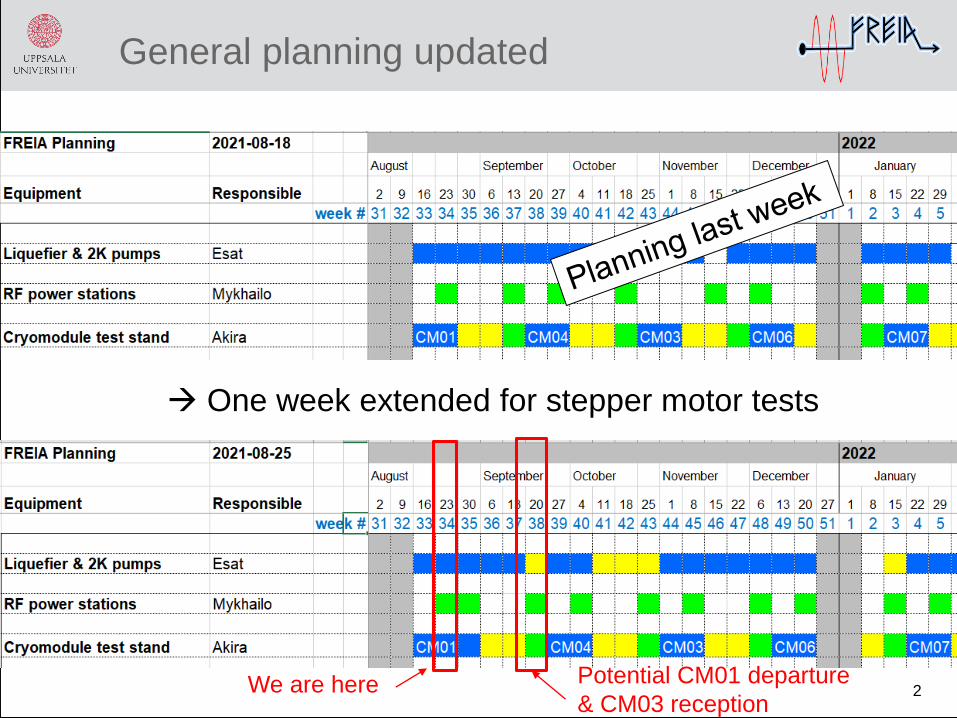
General planning updated
2We are here Potential CM01 departure
& CM03 reception
One week extended for stepper motor tests

SAT SUN
21-aug 22-aug
m a m a m a m a m a
present CM CM01 He purging N2 cooling LHe fillingcoupler cold
conditioning
2K
pumping,
f vs P
RF
calibration,
LLRF
interlock
next CM CM04
thermalize CTS
week
date
4K coolingcavity MP conditioning
up to 12MV/m
no acvitities
W33
MON
16-aug
TUE
17-aug
WED
18-aug
THU
19-aug
FRI
20-aug
SAT SUN
28-aug 29-aug
m a m a m a m a m a
present CM CM01static heat
load
next CM CM04
week
date
W34
MON TUE WED THU FRI
prepare motor driver CTS test at 4K
23-aug 24-aug 25-aug 26-aug 27-aug
no acvitities
SAT SUN
04-sep 05-sep
m a m a m a m a m a
present CM CM012K
pumpingCTS test LFD
dynamics heat
load
cavity
measureme
nt continued
next CM CM04
CTS testcavity measurement
continuedwarming up
doorknob mounting
week W35
date
MON TUE WED THU FRI
30-aug 31-aug 01-sep 02-sep 03-sep
W33&W34 progress and W35 planning
3
We are here
Goal
Phytron driver did not work with
the LabVIEW code from Orsay

Space for 2-3 more modules at FREIA?
4
• Even without the wooden
box, our docking are is
occupied by working place
and plenty of pallets
• We are not allow to leave
anything outside the building
for a few days
• Considering that we anyway
need the box before
transport, having more
module is not an option for us

Let’s start from a good news 1/2
5
CAV IN reached 12MV/m
without field emission

Let’s start from a good news 2/2
6
CAV OUT reached 12MV/m
without field emission

Multipacting bands and X-rays
7
CAV
OUT
CAV
IN
X-ray
detector
2600mm 1100mm
1440m
m
From Mysha

8
Static heat load w/o CTS engaged
1st measurment
2021-08-23 8:43
FT551 = 14,76 SD = 0,58 m3/h
15.70 +/- 0.62 W
PT03_min = 31mbar
PT03_max = 35,5mbar
LT01_min = 59,95cm
LT01_max = 62,19cm
CV551 = 17%
CV03 0%
CV01 0%
CV04 = 100%
2nd measurement
2021-08-23 16:46
FT551 = 14,06 SD = 0,23 m3/h
15.04 +/- 0.25 W
PT03_min = 30,59mbar
PT03_max = 30,89mbar
LT01_min = 60,44cm
LT01_max = 61,76cm
CV551 = 17%
CV03 = 30%
CV01 = 0%
CV04 = 50%
CM05 +1.29 mbar/minCM01 +1.28 mbar/min
CM03 +1.27 mbar/min
Pressure rise method (relative)
CM05
CM01
CM03
They are consistent although CM05 and
CM03 were measured w/ CTS engaged
From linear fitting
1st meas.
2nd meas.
Heat load@2K [W] = 1.07 x mass flow [m3/h]
Mass flow method CM01 preliminary
By Romain & Carl
By Romain & Carl

CTS cooling down curve 1/2
9
Reminder: anomaly in CM03 (by Nicolas)
CM05
CM03
Stepper motor must
be more separated
from the cavity i.e.
higher baseline T
Normal case
Anomalous case
Stepper motor T of CTS1 (broken
motor) reached baseline T of
disengage system (closer to the
cavity)
We speculated that
CTS1 might touch cold
part during cooling down

CTS cooling down curve 2/2
10
Plot from Carl
CM01
Stepper motor T of CTS2 reached
baseline T of disengage system
(closer to the cavity)

Issue 1: Phytron motor driver
11
PC
Phytron driver
motor
RS232-USB
Or
Direct RS232
4 wires
No strange vibration unlike
the one observed by ESS
using the old beckhoff PLC

RS232 works
12
We can rotate the motor by Phytron’s software but
did not know all the engineering parameters

LabVIEW from Orsay does not work
13
This main VI convert physical parameters
we know to engineering parameters
Sub-VI works as
the other software
Main VI does
not work
(communicati
on error)
Decision: wait until
complete instruction
from experts

Fresh news: experts helped this morning
14
David Ledrean@Orsay checked all the parameters
• Three currents setup
• Stop current 0A
• Run current 0.6A
• Boost current not used
• Step resolution 1/8 step
• So that 1600 steps gives one motor shaft turn
• No comment on delay time
• Frequency 2400 Hz
• “Acceleration” needs command-line and “XP15R”
command showed 500000Hz/s which is correct
LabVIEW still does not work but not necessary

Issue 2: FREIA LLRF system 1
15
03-33
03-30
Upper
Circulator
Dir
Coupler
Electrosys RF
Station
Ca
vity
1
Dir
Coupler
RF Switch 1
Circulator
Freia Hall
Bunker
Control room
Band Pass
03-0602-225
6 dB
Splitter
03-23
6 dB
Splitter
03-20
03-19
LLRF ESS
VM
CH0 (1)
Interlock 1
03-0203-03
Attenuator
03-04
LimiterAmp
02-219
PMeter1
Scope/Spectrum
03-18
6 dB
Splitter
03-10
03-09 / NC
03-11
PMeter3
03-16
03-07
3 dB
03-08
03-22CH4 (5)
CH3 (4)
CH5 (6)
Scope
03-31
Compact Rio
Interlock
AI1
Cav Quench Warning?
AI2
LLRF Freia
Attenuator
03-13/NC
AI3
03-17
3.4d
B
03-01
03-24
NC SEL loop ONLY
LimiterLimiter
03-12/NC
Inside RF-Box 1
Inside RF-Box 1
Patch
Panel
Out3 - Pulse Control Signal
2.86 ms pulse lenght @14 Hz
OBS fr system 2
Out2 - Blanking Signal
4 ms pulse lenght @14 Hz
NI5761
NI5782
03-32/NCSEL Loop to Amp over InterLock
switch
LLRF1_BS
50 Ohm Resistor
AI1
AO0
Low Pass
03-05
Signal
Gen
Lo
ad
Load
Cav1 Forward
Cav1 ReflectedFP
C1
Trig1
Trig
RF system 1
Inside RF-Box 1
Cav1 Transmitted
03-15
03-14
P
a
n
e
l
R
3
P
a
n
e
l
R
4
02-204
Psen
PsenPM3chA
Psen
PM1chB
PM1chA
chB
chA
chA
3 dB
03-27
03-29CH1 (2)
03-28
Coupling-box-C1
REF
Cav1
02-203
03-21Band Pass
Band Pass
03-38
03-35
(10.79 dB))
(No Label on connector
side/Be carefull)
02-218
(11.1 dB)
(16.7 dB)
02-225 = Cable Number
(15.4 dB) = Attenuation
30dB84.5dB
(0.7 dB)
(0.4 dB)(1.3 dB)(1.7 dB) (1.3 dB) (0.1 dB)(1.0 dB)
(1.0 dB)
(6.3 dB)
(3 ~ 40 dB) (1.0 dB)
Band Pass
(03-34/NC (from Out3-ONLY if SEL))
Pulse
Gen
03-35 spl
03-39
Trig2
03-36
OBS!
Cable# 1-8 corresponds
to channel# 0-7
Cable# in brackets
Signal
Gen
03-38
3.4dB
03-26
-10dB
03-13/NC = Not Connected
LO
03-37
(PM2)
-20 dB
-20 dB

Issue 2: FREIA LLRF system 1
16
03-33
03-30
Upper
Circulator
Dir
Coupler
Electrosys RF
Station
Ca
vity
1
Dir
Coupler
RF Switch 1
Circulator
Freia Hall
Bunker
Control room
Band Pass
03-0602-225
6 dB
Splitter
03-23
6 dB
Splitter
03-20
03-19
LLRF ESS
VM
CH0 (1)
Interlock 1
03-0203-03
Attenuator
03-04
LimiterAmp
02-219
PMeter1
Scope/Spectrum
03-18
6 dB
Splitter
03-10
03-09 / NC
03-11
PMeter3
03-16
03-07
3 dB
03-08
03-22CH4 (5)
CH3 (4)
CH5 (6)
Scope
03-31
Compact Rio
Interlock
AI1
Cav Quench Warning?
AI2
LLRF Freia
Attenuator
03-13/NC
AI3
03-17
3.4d
B
03-01
03-24
NC SEL loop ONLY
LimiterLimiter
03-12/NC
Inside RF-Box 1
Inside RF-Box 1
Patch
Panel
Out3 - Pulse Control Signal
2.86 ms pulse lenght @14 Hz
OBS fr system 2
Out2 - Blanking Signal
4 ms pulse lenght @14 Hz
NI5761
NI5782
03-32/NCSEL Loop to Amp over InterLock
switch
LLRF1_BS
50 Ohm Resistor
AI1
AO0
Low Pass
03-05
Signal
Gen
Lo
ad
Load
Cav1 Forward
Cav1 ReflectedFP
C1
Trig1
Trig
RF system 1
Inside RF-Box 1
Cav1 Transmitted
03-15
03-14
P
a
n
e
l
R
3
P
a
n
e
l
R
4
02-204
Psen
PsenPM3chA
Psen
PM1chB
PM1chA
chB
chA
chA
3 dB
03-27
03-29CH1 (2)
03-28
Coupling-box-C1
REF
Cav1
02-203
03-21Band Pass
Band Pass
03-38
03-35
(10.79 dB))
(No Label on connector
side/Be carefull)
02-218
(11.1 dB)
(16.7 dB)
02-225 = Cable Number
(15.4 dB) = Attenuation
30dB84.5dB
(0.7 dB)
(0.4 dB)(1.3 dB)(1.7 dB) (1.3 dB) (0.1 dB)(1.0 dB)
(1.0 dB)
(6.3 dB)
(3 ~ 40 dB) (1.0 dB)
Band Pass
(03-34/NC (from Out3-ONLY if SEL))
Pulse
Gen
03-35 spl
03-39
Trig2
03-36
OBS!
Cable# 1-8 corresponds
to channel# 0-7
Cable# in brackets
Signal
Gen
03-38
3.4dB
03-26
-10dB
03-13/NC = Not Connected
LO
03-37
(PM2)
-20 dB
-20 dB
• Signal monitoring, field decay,
LFD, SEL (backup)
• Quench interlock
• Open loop DAC
• fast RF interlocks

Issue 2: FREIA LLRF system 1
17
• Individual modules (ADCs + FPGA) work fine after summer vacation
• Synchronization (trigger) through PXI crate was malfunctioning because of a change
in the system settings Works fine after a correction in settings
• Cause still unknown
• Hard reset after the power failure this summer (thunder storm power-cuts)?
• Some sort of reset or change in the system settings when the RS-232 module
was installed?

SAT SUN
21-aug 22-aug
m a m a m a m a m a
present CM CM01 He purging N2 cooling LHe fillingcoupler cold
conditioning
2K
pumping,
f vs P
RF
calibration,
LLRF
interlock
next CM CM04
thermalize CTS
week
date
4K coolingcavity MP conditioning
up to 12MV/m
no acvitities
W33
MON
16-aug
TUE
17-aug
WED
18-aug
THU
19-aug
FRI
20-aug
SAT SUN
28-aug 29-aug
m a m a m a m a m a
present CM CM01static heat
load
next CM CM04
week
date
W34
MON TUE WED THU FRI
prepare motor driver CTS test at 4K
23-aug 24-aug 25-aug 26-aug 27-aug
no acvitities
SAT SUN
04-sep 05-sep
m a m a m a m a m a
present CM CM012K
pumpingCTS test LFD
dynamics heat
load
cavity
measureme
nt continued
next CM CM04
CTS testcavity measurement
continuedwarming up
doorknob mounting
week W35
date
MON TUE WED THU FRI
30-aug 31-aug 01-sep 02-sep 03-sep
W33&W34 progress and W35 planning
18
We are here
Goal
Phytron driver is OK but doubt
in temperature on stepper
motor during cooling down
2K