Embed Size (px)
Citation preview

ESS 265 Electric Fields 1
Electric Field Measurements• Types of electric field measurements• Double Probe Measurements
– Theory– Measurements in the ionosphere– Measurements in the magnetosphere– The THEMIS electric field experiment
• Further Reading: – Bonnell et al., The THEMIS EFI instrument, Space Science Reviews, 2008.– Maynard, N. C., 1998 Electric field measurements in moderate to high density space plasmas with
passive double probes, in Measurement Techniques in Space Plasmas, AGU Geophys. Monogr. 103, p., 13, 1998.
– Paschmann, G., et al., The electron drift technique for measuring electric and magnetic fields, in Space Plasmas, AGU Geophys. Monogr. 103, p., 39, 1998.
– Pedersen et al., Electric field measurements in a tenuous plasma with spherical double probes, in Measurement Techniques in Space Plasmas, AGU Geophys. Monogr. 103, p. 1, 1998.
– Harvey, P. R., et al., The electric field instrument on the POLAR satellite, Space Sci. Rev., 71, 583, 1995.
– Gustafsson, G., et al., The electric field and wave experiment for the Cluster mission, Space Sci. Rev., 79, 137, 2008.
– Whipple, E. C., Potentials of surfaces in space, Rep. Prog. Phys., 44, 1197, 1981.– Laakso H., and A. Pedersen, Satellite photoemission characteristics, in Materials in a space
environment, edited by H. T. D. Guyenne, pp 361-365, ESA SP-368, ESTEC, Noordwijk, 1994.– Grard, R. J. L., Properties of the satellite photoelectron sheath derived from photoemission
laboratory measurements, J. Geophys. Res., 78, 2885, 1973.

ESS 265 Electric Fields 2
Electric Fields, Overview
Type of E-field Instr. Basic Principle Output quantity / limits
Double Probe direct potential measurement
wave form up to 10Hz 0.5mV/m (10Hz ... DC) compressed data up to 100kHz 50nV/m/Hz
Electron Drift Instrument
ExB drift of emitted electrons (displacement or time of flight measurement)
E field normal to B 0.05mV/m (10Hz ... DC)
All particle Instruments E-field derived from measured velocity distribution and B-field
E field normal to B 0.1..1mV/m depends on plasma (spin period... DC)

ESS 265 Electric Fields 3
Electron Drift Instrument
2BD
BEv
ggD TB
T2
BEvd
nTB
mmVEm
24 /
1057.3d
eg
D T
tvv
2
geT
m2B
Measurement of displacement
Measurement of time of flight
E-field measurement - EDI (1)
V1
V2gun
detector
d
t1=t0+Tg(1+VD/Ve)t2=t0+Tg(1-VD/Ve)
t2
t1
t0
Tg=((t1-t0)+(t2-t0))/2
ESS 265 Electric Fields 4
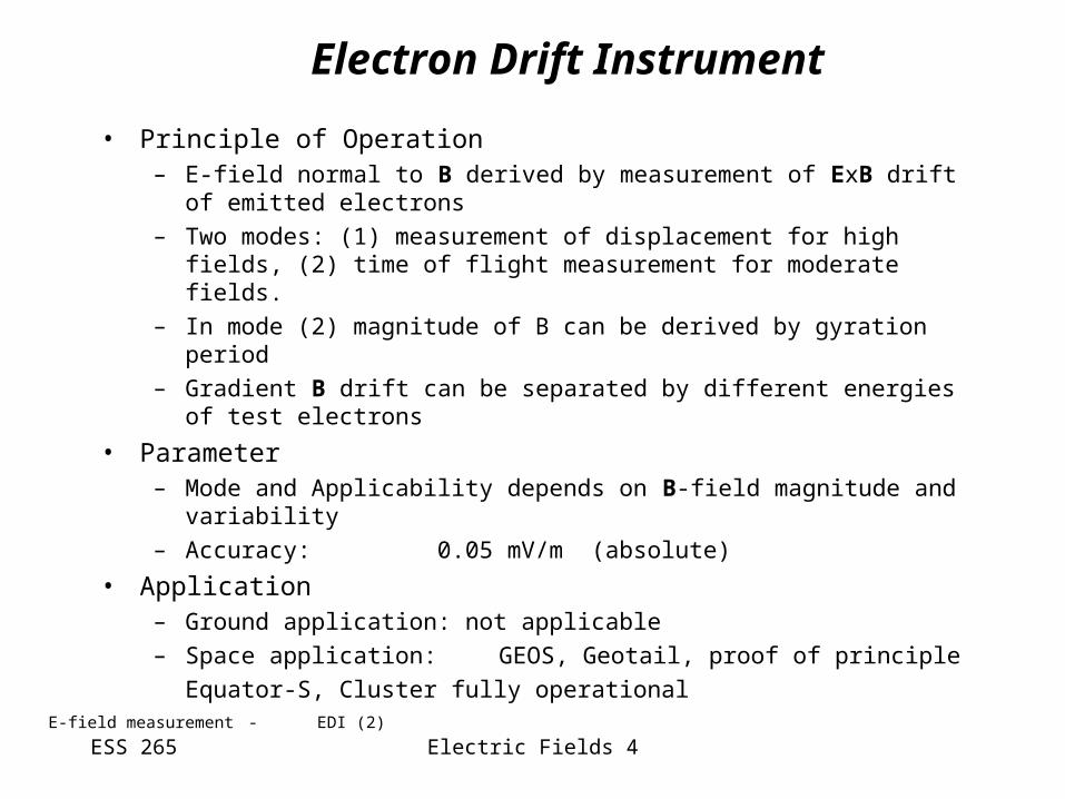
• Principle of Operation– E-field normal to B derived by measurement of ExB drift of emitted
electrons
– Two modes: (1) measurement of displacement for high fields, (2) time of flight measurement for moderate fields.
– In mode (2) magnitude of B can be derived by gyration period
– Gradient B drift can be separated by different energies of test electrons
• Parameter– Mode and Applicability depends on B-field magnitude and variability
– Accuracy: 0.05 mV/m (absolute)
• Application– Ground application: not applicable
– Space application: GEOS, Geotail, proof of principle
Equator-S, Cluster fully operational
Electron Drift Instrument
E-field measurement - EDI (2)

ESS 265 Electric Fields 5
Double Probe
dBvE d/21
[Pedersen et al., 1998] [N.C.Maynard, 1998]
E-field measurement - Double Probe (1)

ESS 265 Electric Fields 6
• Principle of Operation– Direct measurement– Only method which can be used to measure E||
• Parameter– Noise at 1Hz: 10-5 V/m/sqrt(Hz)– Noise at 100 kHz: 10-9 V/m/sqrt(Hz)
• Application– Ground application:
EM-sounding– Space application:
sounding rockets andall magnetosphere missionssince late 60s
Double probe
[D.A.Gurnett, 1998] E-field measurement - Double Probe (2)

ESS 265 Electric Fields 7
Double Probe
• Problem areas– Large probe separation necessary to increase signal, wire booms
are used normal to spin axis, boom for spin axis component difficult
ephimeasurscephretepheplasma IIIIII
[Pedersen et al., 1998] E-field measurement - Double Probe (3)

ESS 265 Electric Fields 8
SW M´sheath M´sphereBS MP
E-Field Examples
Electric Fields from EFW, EDI & CIS; [Eriksson et al., 2003]Examples - E-field

ESS 265 Electric Fields 9
E&M Instrumentation on Cluster
• Fluxgate Magnetometer, FGM– PI: Andre Balogh IC London
– Dual Sensor (3.1m & 5.1m distance) analogue FG
• Search Coil Magnetometer, STAFF– PI: Nicole Cornilleau-Wehrlin,
– Three component boom mounted sensor
• Double Probe, EFW– PI: Mats Andre, IRFU Uppsala
– Two sets of wire booms in spin plane
• Electron Drift Experiment, EDI– PI: Götz Paschmann, MPE Garching
– Two gun/sensor system
Examples - Cluster

ESS 265 Electric Fields 10
E&M Instrumentation on Themis
• Fluxgate Magnetometer, FGM– K.H. Glassmeier, TU-Braunschweig
– Single sensor (2m boom), digital electronics
• Search Coil Magnetometer, SCM– A.Roux, CEPT
– The SCM 3-axis antennas are located at the end of 1 meter SCM boom
• Double Probe, EFI– J.Bonell, UCB
– Two sets of wire booms in spin plane
– One set of axial booms
Examples - Themis

ESS 265 Electric Fields 11
• Boom Geometry– 1-3 segment boom (Cluster Double Star, Themis ...)– Boom made by spring elements (MMO)– Wire Booms (Cluster, Themis ...)
• Release & launch lock mechanism– Doors:
• Pyro (Cluster)• Shaped Memory Alloy (Themis)
– Wires: motor driven– Axials: Stacers
• Deployment force– Centrifugal force– Motor driven
E&M Sensor Accommodation
Requirements on S/C - Booms

ESS 265 Electric Fields 12
• Debye shielding, D=(kTe/Ne2)1/2
– Homework#1: Derive potential at 1-D grid is =oexp(-|x|/ D)
• Ambient electron current collected by probe– Ie=Ie0exp(V/Ve), V<0 where: Ve=kTe/e– Ie= Ie0(1+V/Ve), V>0 where: Ie0=-A e ne sqrt(kTe/2me) – Homework #2: Prove this
• Ambient ion current collected by probe– Ii= Ii0(1-V/Ve), V<0– Ii=Ii0exp(-V/Ve), V>0 where: Ii0= Ie0 / sqrt(mi/me)– Homework #3: assuming Ii+Ie=0, show that
• Floating potential = kTe sqrt(mi/me)• Ion saturation current, when V<<0, is: Isat=Ii0= A e ne sqrt(kTe/2mi)
• Once Isat is found, slope gives kTe, and A gives ne– This is operational principle of Langmuir probes
Double Probe Theory
ESS 265 Electric Fields 13
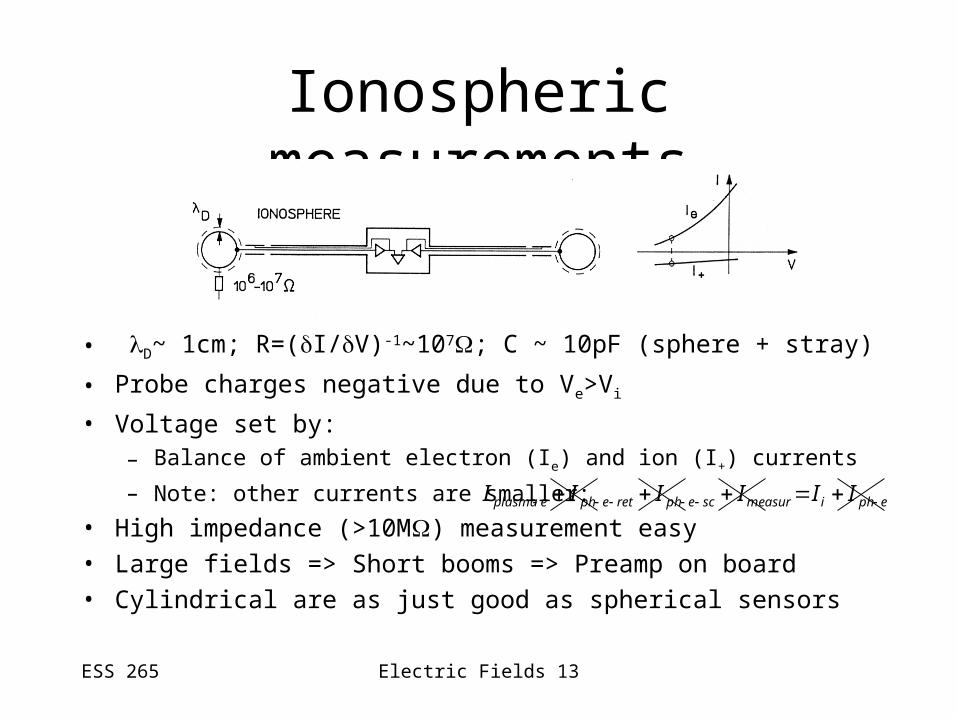
Ionospheric measurements
• D~ 1cm; R=(I/V)-1~107; C ~ 10pF (sphere + stray)
• Probe charges negative due to Ve>Vi
• Voltage set by:– Balance of ambient electron (Ie) and ion (I+) currents
– Note: other currents are smaller:
• High impedance (>10M) measurement easy
• Large fields => Short booms => Preamp on board
• Cylindrical are as just good as spherical sensors
ephimeasurscephretepheplasma IIIIII

ESS 265 Electric Fields 14
Ionospheric measurements: problems
1st order problem Mitigation
• Velocity wake Avoid: 3axis stabilized spacecraft
2nd order problems Mitigation
• Photoemission Use spherical sensors
• Body photoelectrons Repel with guards
Others (see Maynard, N. Table 1).

ESS 265 Electric Fields 15
• D~ 500m; R=(I/V)-1 ~109; C ~ 4.5pF (sphere)• Probe positive due to photoemission (Ia). Ie is from plasma.
– Other currents are (or made) negligible:– In practice 1st order error (and correction) comes from Iph-e-sc and Iph-e-ret
• Resistive coupling to plasma through photoemission– Bias current
• reduces dynamic resistance• reduces potential w/r/t plasma• makes measurement feasible unless bias
ephimeasurscephretepheplasma IIIIII
Magnetospheric measurements
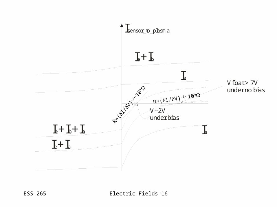
ESS 265 Electric Fields 16
Ie
Ia
Vfloat > 7Vunder no bias
Ie+Ib
Isensor_to_plasma
V~2Vunder bias
Ie+I +Ib a
Ie+Ia
R=(I/V)-1~109
R=(I
/V)-
1 ~10
7

ESS 265 Electric Fields 17
Magnetospheric measurements• Photoelectron current: analytical
– Ia=Iao,V<0, Ia0=(S/4) ja0 ; where:
• S=sphere surface area
• ja0 depends on materials and ambient plasma
– Ia=Iao(1+V/Vph)exp(-V/Ve), Vph = kTph/e, V>0
– Further reading: Grard, 1973
• Photoelectron current: empirical (x4)– ja=80(Am-2)exp(-V/2)+3(Am-2)exp(-V/7.5); V in Volts
– Further reading: Laakso and Pedersen, 1994
• Objective:– Bias current such that potential only 1-2Volts above plasma
• Coupling:– Resistive below 1/RsCs ~ 100Hz; capacitive above it

ESS 265 Electric Fields 18
Potential distribution

ESS 265 Electric Fields 19
Magnetospheric measurements: problems
1st order problems Mitigation• Sensor asymmetric photoemission Constrain s/c pot with guards• Body photoelectrons Repel with guards• Ion wake Longer booms• Axial: no DC Make symmetric
spacecraft Electrostatically clean
Obtain Eaxial from E*B=0
2nd order problems Mitigation• Shielding of external field by sc Use negative guards, or
…live with it• Magnetic wake Live with it