Embed Size (px)
Citation preview
Division / Business Unit: Enterprise Services
Function: Signalling
Document Type: Standard
© Australian Rail Track Corporation Limited (ARTC)
Disclaimer
This document has been prepared by ARTC for internal use and may not be relied on by any other party without ARTC’s prior written consent. Use of this document shall be subject
to the terms of the relevant contract with ARTC.
ARTC and its employees shall have no liability to unauthorised users of the information for any loss, damage, cost or expense incurred or arising by reason of an unauthorised user
using or relying upon the information in this document, whether caused by error, negligence, omission or misrepresentation in this document.
This document is uncontrolled when printed.
Authorised users of this document should visit ARTC’s intranet or extranet (www.artc.com.au) to access the latest version of this document.
CONFIDENTIAL Page 1 of 42
Common Signal Design Principles
S1 - Signalling Locking and Train
Dynamics
ESD-05-01
Applicability
ARTC Network Wide
Publication Requirement
Internal / External
Primary Source
Document Status
Version Date Reviewed Prepared by Reviewed by Endorsed Approved
3.0 13 Oct 15 Standards Stakeholders Manager
Standards
Operational Safety & Environment
Review Committee 13/10/2014
GM Technical Standards 30/11/2015
Amendment Record
Version Date Reviewed Clause Description of Amendment
3.0 21 Oct 14
26 Jun 15
13 Oct 15
6.2.7
Various
6.2.6
Various
New Clause 6.2.7 Provision of Overlaps for Modified Simultaneous
Entry at a Crossing Loop (approved by OSERC 13/10/2014). Further
minor editorial amendments throughout for consistent terminology and
removal of superseded reference documents. Clause 6.2.6 previously
applicable to NSW only now extended to network wide applicability.
Rebranded.
Common Signal Design Principles S1 - Signalling Locking and Train Dynamics
ESD-05-01
Table of Contents
This document is uncontrolled when printed. Version Number: 3.0 Date Reviewed: 13 Oct 15 Page 2 of 42
Table of Contents
Table of Contents ............................................................................................................................................. 2
1 Introduction ............................................................................................................................................. 4
1.1 Purpose .......................................................................................................................................... 4
1.2 Document Owner ........................................................................................................................... 4
1.3 Reference Documents ................................................................................................................... 4
2 Route Locking ......................................................................................................................................... 5
2.1 Designation of Class and Direction of Routes ............................................................................... 5
2.2 General Locking Arrangements within Routes and Overlaps ........................................................ 7
2.3 Approach Locking .......................................................................................................................... 8
2.4 Route Holding (Route Locking) .................................................................................................... 10
3 Point Locking ........................................................................................................................................ 13
3.1 General Point Locking Requirements .......................................................................................... 13
3.2 In-Route Points............................................................................................................................. 14
3.3 Self Normalising Points for Traps and Catch Points .................................................................... 14
3.4 Self Restoring Points for Crossing Loops .................................................................................... 14
3.5 Yard Entrance/Exit ....................................................................................................................... 14
3.6 Points Sequencing ....................................................................................................................... 14
3.7 Derailment at Catch Points .......................................................................................................... 14
3.8 Detection of Points ....................................................................................................................... 14
3.9 Track Circuit Locking of Points ..................................................................................................... 20
4 Headway ................................................................................................................................................ 22
4.1 Headway Concepts and Definitions ............................................................................................. 22
4.2 Signal Spacing ............................................................................................................................. 22
4.3 Sighting Point & Distance ............................................................................................................. 22
4.4 Distance between Running Signals ............................................................................................. 23
5 Braking Distance Concepts and Definitions ..................................................................................... 24
5.1 Definitions ..................................................................................................................................... 24
5.2 Braking Distance in Signalling Systems ....................................................................................... 24
6 Overlaps Concepts and Definitions .................................................................................................... 26
6.1 Overlap – Definition ...................................................................................................................... 26
6.2 Overlaps for Colour Light Running Signals .................................................................................. 26
6.3 Overlaps in ETS and OTS Territory where Colour Light Running Signals are Provided ............. 31
Common Signal Design Principles S1 - Signalling Locking and Train Dynamics
ESD-05-01
Table of Contents
This document is uncontrolled when printed. Version Number: 3.0 Date Reviewed: 13 Oct 15 Page 3 of 42
6.4 Overlaps in Train Order Working Areas ....................................................................................... 32
6.5 Conditional Overlaps .................................................................................................................... 32
6.6 Locking Opposing Routes Leading into or Situated within an Overlap ........................................ 33
6.7 Setting and Locking of Points within an Overlap.......................................................................... 34
6.8 Setting and Locking of Points within an Overlap at a Crossing Loop in CTC Territory ............... 37
6.9 Overlaps for Low Speed Subsidiary Signals in Route Signalling Territories ............................... 38
6.10 Overlaps for Subsidiary, Ground Shunting or Low Speed Route Signalling ................................ 38
6.11 Preferential Setting of Conditionally Locked Points in an Overlap ............................................... 38
6.12 Automatic Overlap Setting by Track Circuit Operation ................................................................ 39
6.13 Overlap Swinging ......................................................................................................................... 40
7 Block Sections ...................................................................................................................................... 42
Common Signal Design Principles S1 - Signalling Locking and Train Dynamics
ESD-05-01
Introduction
This document is uncontrolled when printed. Version Number: 3.0 Date Reviewed: 13 Oct 15 Page 4 of 42
1 Introduction
1.1 Purpose
The purpose of this Standard is to address:
• The requirements for the provision of route holding as a means of maintaining locking by the
occupation of track circuits once a train has entered a route and the signal has been replaced
to stop and the route normalised
• The requirements for the provision of Interlocking between signals (routes), points and ground
frames
• The requirements for the provision of approach locking on signals and the methods and
conditions under which it is applied and released
• The requirements for the provision of time releases for various signalling functions and
discusses the methods of determining time release expiry periods
• The concepts and definitions relating to certain types of points
• The concept of an overlap to provide a margin of safety between following trains and provides
definition for of the terms associated with overlaps
• The concept of headway and provides further definitions and concepts for the various factors
affecting headway
• The concepts and definitions of braking distance and its effect on the requirements and design
of a signalling system.
1.2 Document Owner
The Manager Standards is the document owner and is the initial point of contact for all queries
relating to this Standard.
1.3 Reference Documents
The following documents were considered in developing the ARTC common Signal Design
Principles:
Reference ARTC Documents:
• SCP 01 Signalling Control Systems
• SDS 03 Braking Distance
• SDS 04 Overlaps
Reference QR Principles:
• S.07.4211.27 Regional RCS
Reference Victoria Specification and Guideline:
• ENG-SE-SPE-0001 Signal Design and Documentation
Reference WA Principles:
• WAGR Code of Practice 8190-600-004 Signal Design Principles – Urban

Common Signal Design Principles S1 - Signalling Locking and Train Dynamics
ESD-05-01
Route Locking
This document is uncontrolled when printed. Version Number: 3.0 Date Reviewed: 13 Oct 15 Page 5 of 42
2 Route Locking
2.1 Designation of Class and Direction of Routes
2.1.1 Introduction
This Principle addresses the requirements for designating the class and/or direction of routes as
applicable to running signals, running signals fitted with subsidiary and shunting signals in colour
light territory. Running Signal or Route proves track section occupancy and points etc. Subsidiary
Signal or Route proves the points position and not track section occupancy.
Signal Indications, meaning and application for both speed and route signalling are detailed in the
Code of Practice for the Defined Interstate Rail Network, in volume 3.1, Operations and
Safeworking – Rules, Tables 3.1 to 3.3.
2.1.2 Class of Route
2.1.2.1 Running (Main) Routes
Main routes are characterised as being intended to be used for a running move where the train
speed is dictated by the track geometry and speed boards only, unless there are operational
requirements for speed restrictions.
Main routes commence at a main signal and end at another main signal, a stop board acting as a
main signal or a buffer stop.
Routes classified as main routes shall be designated (M) as a prefix after the signal number or ID.
Refer to figure 1.
Figure 1 – Main Route
2.1.2.2 Subsidiary (Shunt) Routes
Subsidiary (shunt) routes are characterised by being intended to be used for moves taken at low
speeds, with the train driver being responsible for ensuring that the train can be stopped clear of
any obstruction. The proceed aspect on this signal does not prove that the track sections within the
subsidiary route are unoccupied.
Subsidiary routes commence at a subsidiary signal beneath a main stop signal and end at another
shunt signal, a main signal, a buffer stop, a stop board, a limit of shunt (LOS) board or in a siding or
yard.
Shunt routes commence at a shunting signal or from a ground frame and end at another shunt
signal, a main signal, a buffer stop, a stop board, a limit of shunt (LOS) board or in a siding or yard.
Routes classified as subsidiary or shunt routes shall be designated (S or LS) as a prefix after the
signal number or ID. Refer to figures 2A & 2B.
Common Signal Design Principles S1 - Signalling Locking and Train Dynamics
ESD-05-01
Route Locking
This document is uncontrolled when printed. Version Number: 3.0 Date Reviewed: 13 Oct 15 Page 6 of 42
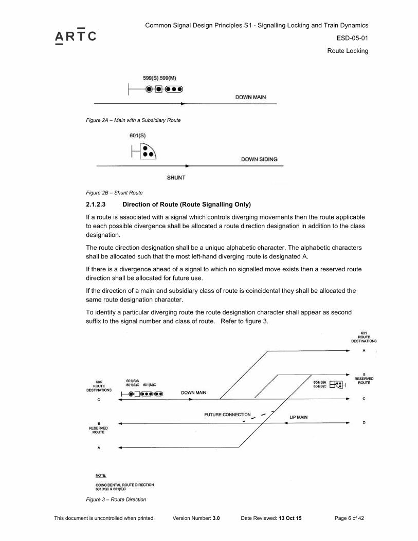
Figure 2A – Main with a Subsidiary Route
Figure 2B – Shunt Route
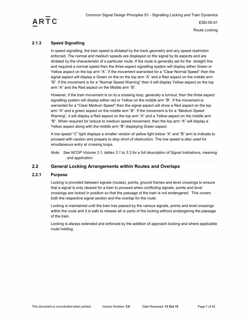
2.1.2.3 Direction of Route (Route Signalling Only)
If a route is associated with a signal which controls diverging movements then the route applicable
to each possible divergence shall be allocated a route direction designation in addition to the class
designation.
The route direction designation shall be a unique alphabetic character. The alphabetic characters
shall be allocated such that the most left-hand diverging route is designated A.
If there is a divergence ahead of a signal to which no signalled move exists then a reserved route
direction shall be allocated for future use.
If the direction of a main and subsidiary class of route is coincidental they shall be allocated the
same route designation character.
To identify a particular diverging route the route designation character shall appear as second
suffix to the signal number and class of route. Refer to figure 3.
Figure 3 – Route Direction
Common Signal Design Principles S1 - Signalling Locking and Train Dynamics
ESD-05-01
Route Locking
This document is uncontrolled when printed. Version Number: 3.0 Date Reviewed: 13 Oct 15 Page 7 of 42
2.1.3 Speed Signalling
In speed signalling, the train speed is dictated by the track geometry and any speed restriction
enforced. The normal and medium speeds are displayed on the signal by its aspects and are
dictated by the characteristic of a particular route. If the route is generally set for the straight line
and required a normal speed then the three aspect signalling system will display either Green or
Yellow aspect on the top arm “A”. If the movement warranted for a “Clear Normal Speed” then the
signal aspect will display a Green on the on the top arm “A” and a Red aspect on the middle arm
“B”. If the movement is for a “Normal Speed Warning” then it will display Yellow aspect on the top
arm “A” and the Red aspect on the Middle arm “B”.
However, if the train movement is on to a crossing loop, generally a turnout, then the three aspect
signalling system will display either red or Yellow on the middle arm “B”. If the movement is
warranted for a “Clear Medium Speed” then the signal aspect will show a Red aspect on the top
arm “A” and a green aspect on the middle arm “B”. If the movement is for a “Medium Speed
Warning”, it will display a Red aspect on the top arm “A” and a Yellow aspect on the middle arm
“B”. When required for reduce to medium speed movement, then the top arm “A” will display a
Yellow aspect along with the middle arm “B” displaying Green aspect.
A low speed “C” light displays a smaller version of yellow light below “A” and “B” arm to indicate to
proceed with caution and prepare to stop short of obstruction. The low speed is also used for
simultaneous entry at crossing loops.
Note: See NCOP Volume 3.1, tables 3.1 to 3.3 for a full description of Signal Indications, meaning
and application
2.2 General Locking Arrangements within Routes and Overlaps
2.2.1 Purpose
Locking is provided between signals (routes), points, ground frames and level crossings to ensure
that a signal is only cleared for a train to proceed when conflicting signals, points and level
crossings are locked in position so that the passage of the train is not endangered. This covers
both the respective signal section and the overlap for the route.
Locking is maintained until the train has passed by the various signals, points and level crossings
within the route and it is safe to release all or parts of the locking without endangering the passage
of the train.
Locking is always extended and enforced by the addition of approach locking and where applicable
route holding.
Common Signal Design Principles S1 - Signalling Locking and Train Dynamics
ESD-05-01
Route Locking
This document is uncontrolled when printed. Version Number: 3.0 Date Reviewed: 13 Oct 15 Page 8 of 42
2.2.2 Requirements - General Locking within a Route and an Overlap
If a route from a signal conflicts with another route on the same signal or leads over one or more
sets of points or ground frames or reads up to one or more opposing signals (routes) then it shall;
i. lock normal any conflicting routes leading away from the same signal;
ii. lock normal any opposing signal routes which lead into the route or its overlap;
iii. lock normal or reverse as required any sets of points in line with the direction of the route
together with any points providing trap or flank protection to the route or its overlap;
iv. lock any ground frames normal in the route or its overlap;
v. lock any trailing points in its overlap in the appropriate direction for which the overlap is set, in
South Australia trailing or facing points in the overlap are not locked in legacy Interlockings;
vi. lock normal or reverse any facing points in its overlap only if other locking conditions within or
leading into the overlap make this necessary. Converse locking shall always be applied except
in special cases;
2.3 Approach Locking
2.3.1 Purpose
Approach locking is provided to prevent an operator or an auto-normalisation call from normalising
a route ahead of an approaching train which could allow a change to a route that might endanger
the passage of the train.
Approach locking is normally applied to any signal routes which are interlocked. The approach
locking becomes effective when the signal has been called to clear and all conditions for clearance
are proved available
If a controlled signal has one or more routes which directly or indirectly interlock with other routes
on the same or on other signals or with points or ground frames or level crossings then the signal
shall be provided with approach locking.
2.3.2 Running Signals
The approach locking shall become effective if a proceed aspect has been displayed in the
approached locked signal and the driver of an approaching train has sighted a signal showing a
proceed aspect which would be altered by the replacement of the approach locked signal back to
stop.
Once initiated the approach locking shall be maintained by the occupation of the track circuits over
the appropriate approach locking distance in rear of the signal which is approach locked.
If a running signal is situated such that the number of aspects which can be displayed in rear are
restricted due to physical or operational constraints of the system then the extent of the approach
locking may be reduced accordingly.
If a running signal is situated such that no track circuit is provided in rear then it shall be approach
locked immediately it displays a proceed aspect.
2.3.3 Subsidiary Shunt Aspects or Low Speed Aspects for Speed Signalling
The approach locking shall become effective if a proceed aspect has been displayed in the signal
to be approached locked and an approaching train has passed the running signal immediately in
Common Signal Design Principles S1 - Signalling Locking and Train Dynamics
ESD-05-01
Route Locking
This document is uncontrolled when printed. Version Number: 3.0 Date Reviewed: 13 Oct 15 Page 9 of 42
rear and is within sighting distance of the signal and is within 600m of the signal or when the signal
is cleared.
The approach locking once initiated shall be maintained by the occupation of the track circuits over
the appropriate approach locking distance in rear of the signal which is approach locked. The
approach locking point may commence 600m or sighting distance in rear of the approach locked
signal or from the first signal in rear as the case may be.
2.3.4 Ground Shunting Signals
The approach locking shall become effective if a proceed aspect has been displayed in the signal
to be approach locked and an approaching train has passed the signal in rear and is within sighting
distance of the signal and is within a distance of 300m of the signal to be approach locked.
If a shunting signal is situated such that no track circuit is provided in rear then it shall be approach
locked immediately it displays a proceed aspect.
2.3.5 Release of Approach Locking
Approach locking shall be released by the signal at stop and the passage of the train past the
signal which is approach locked or after the expiry of a time period to allow for the train to be nearly
at or have come to a stand at the approach locked signal, or the train being otherwise proved to
have come to a stand. Where there is no train within the approach area, then the approach locking
may be released upon signal cancellation.
2.3.6 Running Signal
The approach locking shall be released by the normal passage of the train over the first and
second track circuits in sequence immediately past the approach locked signal and in the direction
for which the route is set, or following a time release, which shall commence timing immediately the
approach locked signal has been replaced to stop.
The standard time releases for approach locking are 240 seconds for running and subsidiary
signals, or 120 seconds if the start of the breaking point is not fully track circuited and 30 seconds
for ground shunt signals. Where the subsidiary signal has a separate approach lock to the main
signal than the time release for the approach locking on the subsidiary signal may be 60 seconds.
Other times may apply at specific locations and consideration shall be given to the distance
between signals when determining the time release period. As this distance increases, it is
necessary to increase the approach locking time release period to reasonably ensure the train has
come to a stand. This is to be applied where the proceeding signal is greater than the train braking
distance.
Where a crossing loop is greater than 1500m, then a minimum time release period of 180 seconds
shall be applied.
2.3.7 Subsidiary Shunt Aspects or Low Speed Aspects for Speed Signalling
The approach locking shall be released by the normal passage of the train over the first track circuit
immediately past the approach locked signal, or following the expiry of a time release which shall
commence timing immediately the approach locked signal has been replaced to stop.
The time release expiry period shall be 60 seconds. The subsidiary shunt aspect time release
period may be equal to that of the main aspect under particular operating conditions.
Common Signal Design Principles S1 - Signalling Locking and Train Dynamics
ESD-05-01
Route Locking
This document is uncontrolled when printed. Version Number: 3.0 Date Reviewed: 13 Oct 15 Page 10 of 42
2.3.8 Ground Shunting Signals
The approach locking shall be released by the normal passage of the train over the first track circuit
immediately in advance of the approach locked signal or following the expiry of a time release
which shall commence timing immediately the approach locked signal has been replaced to stop.
The time release expiry period shall be 60 seconds.
In freight yards, ground shunt signals may have a time releases of 30 seconds if there is an
approach track circuit.
2.3.9 Release of Approach Locking with Simplified Auto normalisation
Where automatic normalising of the signal is provided by occupancy of the A track circuit alone
(e.g. One Control Switch (OCS) type systems), the track occupied release of approach locking is
not to be provided for main running aspects.
Where there is a need for a track occupied release (e.g. on certain subsidiary signals), selection
shall be incorporated to ensure that the track occupied release is not effective for main running
aspects.
2.3.10 Signals Stepping from Shunt to Main Aspect
It is permissible for signals to step up directly from a shunt aspect to a main aspect without first
releasing approach locking. However, it is not permissible for a signal to step down from a main to
a shunt aspect where less restrictive locking is applied without release of the approach locking.
2.4 Route Holding (Route Locking)
2.4.1 Purpose
Route holding is provided to maintain the effect of route to route or route to points or similar locking
by the occupation of track circuits between the functions concerned.
The route holding becomes effective once a train has entered the route and the initiating signal
replaced to stop and the route normalised.
In some circumstances a time release is required to free route holding.
2.4.2 Requirements - Holding of Locking Between Opposing Routes
If opposing routes are situated such that the occupation of an intervening track circuit is in itself
insufficient to maintain the aspects of opposing signals at stop, then this shall be enforced by the
provision of route holding between the signals concerned. This will be required between main and
main signals and between main and shunt signals, (this may be achieved via points – see figure 4).
Common Signal Design Principles S1 - Signalling Locking and Train Dynamics
ESD-05-01
Route Locking
This document is uncontrolled when printed. Version Number: 3.0 Date Reviewed: 13 Oct 15 Page 11 of 42
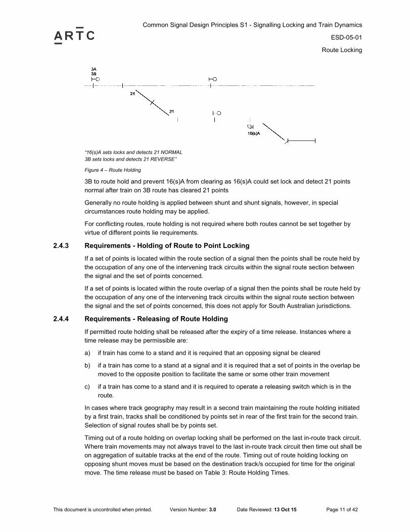
“16(s)A sets locks and detects 21 NORMAL
3B sets locks and detects 21 REVERSE’’
Figure 4 – Route Holding
3B to route hold and prevent 16(s)A from clearing as 16(s)A could set lock and detect 21 points
normal after train on 3B route has cleared 21 points
Generally no route holding is applied between shunt and shunt signals, however, in special
circumstances route holding may be applied.
For conflicting routes, route holding is not required where both routes cannot be set together by
virtue of different points lie requirements.
2.4.3 Requirements - Holding of Route to Point Locking
If a set of points is located within the route section of a signal then the points shall be route held by
the occupation of any one of the intervening track circuits within the signal route section between
the signal and the set of points concerned.
If a set of points is located within the route overlap of a signal then the points shall be route held by
the occupation of any one of the intervening track circuits within the signal route section between
the signal and the set of points concerned, this does not apply for South Australian jurisdictions.
2.4.4 Requirements - Releasing of Route Holding
If permitted route holding shall be released after the expiry of a time release. Instances where a
time release may be permissible are:
a) if train has come to a stand and it is required that an opposing signal be cleared
b) if a train has come to a stand at a signal and it is required that a set of points in the overlap be
moved to the opposite position to facilitate the same or some other train movement
c) if a train has come to a stand and it is required to operate a releasing switch which is in the
route.
In cases where track geography may result in a second train maintaining the route holding initiated
by a first train, tracks shall be conditioned by points set in rear of the first train for the second train.
Selection of signal routes shall be by points set.
Timing out of a route holding on overlap locking shall be performed on the last in-route track circuit.
Where train movements may not always travel to the last in-route track circuit then time out shall be
on aggregation of suitable tracks at the end of the route. Timing out of route holding locking on
opposing shunt moves must be based on the destination track/s occupied for time for the original
move. The time release must be based on Table 3: Route Holding Times.
Common Signal Design Principles S1 - Signalling Locking and Train Dynamics
ESD-05-01
Route Locking
This document is uncontrolled when printed. Version Number: 3.0 Date Reviewed: 13 Oct 15 Page 12 of 42
The Time Releasing shall be determined by calculating the time taken for a train running at a
consistent speed to pass over the timing track circuit. If the timing track circuit is 200m or less then
this speed shall be taken as 15kph. If the length of the timing track circuit is greater than 200m then
this speed shall be taken as 25kph. The time calculated by this method shall then be rounded up to
the next 15 seconds.
Where the stop signal ahead is situated some longer distance back from the potential fouling point
then consideration may be given to a commensurate increase in the average speed used for
calculating the time release period. This calculated time shall be shown in the Control Tables up to
a maximum of 35kph.
Releasing arrangements are to take into account the method of operation of the interlocking and
shunting arrangements. For main line movements timing shall require berth track occupancy,
however, for locations where ground frames are provided, the timing track should be local to the
ground frame and extend approximately 100m either side.
Consideration should be given to having a time release for the full length of the route in addition to
a time release for a final track circuit in the route.
Long timing over a number of track circuits (e.g. in a loop) may be necessary to meet operational
needs.
Common Signal Design Principles S1 - Signalling Locking and Train Dynamics
ESD-05-01
Point Locking
This document is uncontrolled when printed. Version Number: 3.0 Date Reviewed: 13 Oct 15 Page 13 of 42
3 Point Locking
3.1 General Point Locking Requirements
a) Points shall not be free to move until the tracks that directly or indirectly lock point movements,
have been continuously energised for 1 second minimum.
b) Pre-selection of signalling routes over points shall not be permitted. Points selection circuits
shall be designed to be non-storage regardless of type of operation. With Train Control
systems pre-storage of route requests is permissible where a request function is part of the
route request.
c) Points motors/valves (excluding E.P. and clamplocks) shall be controlled by normal and
reverse contactors of BRB 966-F4 or QBCA1 or equivalent type with heavy duty contacts.
d) Contacts of point 'Isolating Relays’ where applicable shall be in each point motor circuit, to
control the point motor power supply. These shall only be energised to drive the points. The
circuit function shall include the contact of the local track relay in preference to a repeat relay.
The isolating relay shall double switch the point motor circuit.
e) Points contactors and IR relays are to be mounted adjacent to each other in the nearest
location case, walk-in or relay room.
f) Back proving of both 'A' and 'D' contact stacks of the BRB 966-F4 or QBCA1 or equivalent
relay shall be carried out.
g) The emergency on site operation of point machines will be made possible by the use of an
emergency crank handle or manual lever.
h) Where applicable, when the points crank handle is removed from the Annett lock, the power
supply to the point motor will be cut off and all signals interlocked with the points held at stop.
This is achieved by cutting the detector relays and isolating relay circuits.
i) There shall be a lever to select motor or manual operation in the cases of dual control point
machines. This lever shall be normally locked in the motor position with a padlock which is
released by the nominated operation key, see network rules. The lever in the manual position
shall isolate the motor and detection circuit.
j) A timing device shall be provided for all points to cut the feed to the point motor if its running
time exceeds 300% of its normal running time. This timing device shall be re-set if the point
control is operated to return the points to the other position.
k) Where magnetic contactors are utilised in the machine, checking of the opposing lock relay
should be performed in the detector circuit. In this case the ESML/EOL contacts should cut
both the detector circuit and the isolating relay.
l) Facing points in the overlap are generally not locked.
Release of Point locking is achieved by one of the following:
a) Timing out of the approach locking with a train on the approach tracks, or
b) Occupation of the last in-route track for a time as specified in Table 3: Route Holding Times, or
c) Occupation of group track circuits within the route as specified in the control tables, or
d) Passage of the train through the route (i.e., train has proceeded past the next signal), or
e) Cancellation of the signal, providing the approach locking is released.
Common Signal Design Principles S1 - Signalling Locking and Train Dynamics
ESD-05-01
Point Locking
This document is uncontrolled when printed. Version Number: 3.0 Date Reviewed: 13 Oct 15 Page 14 of 42
3.2 In-Route Points
When the points track is the first in-route track, the points are locked by the signal called and
maintained by either the signal’s approach locking or the points track occupied. Where the points
are not situated in the first in-route track, route holding is required to lock the points in the required
lie. It shall be initiated by the signal called, and held by either the signal’s approach locking or the
occupation of tracks between the signal and the points track.
3.3 Self Normalising Points for Traps and Catch Points
Self normalisation may be provided for trap and catch points on sidings which protect the main line.
Where self normalisation is specified in the signalling arrangement, the points shall be set to
normal when the points have been continuously free to move for a period not less than 45 seconds.
The timing and points call functions are implemented in the control centre.
3.4 Self Restoring Points for Crossing Loops
Self restoring points may be provided for crossing loops. The points shall restore to normal after
the passage of the train and when the points have been continuously free to move for a period not
less than 3 seconds. The timing of the points call function is implemented in the interlocking
equipment.
3.5 Yard Entrance/Exit
Shunting yard entry/exit points protecting main routes past the yard are to be locked by those main
routes to protect main route and overlaps where there is the possibility of a shunt coming loose
within the yard and travelling in an opposing or flank direction towards that route or overlap where
the distance from the yard entrance/exit to the point of conflict is less than 250m, or as otherwise
determined by the Signal Design Authority.
3.6 Points Sequencing
Sequencing of the motoring points machines may be used where there is insufficient power
capacity available through cabling or back up power supplies. Detection of the initial points or time
out of the cut-out timer to ensure the points are not motoring is required to before subsequent
points can be motored.
3.7 Derailment at Catch Points
Where vehicles that have been derailed by catch points are likely to be foul (as defined in
S.07.42111.20 Bonding and Track Clearance Points) of a main running line, a means (e.g. a circuit
interrupter) shall be provided to prevent the clearing of signals along the main running line when
vehicles have been derailed by the catch points.
3.8 Detection of Points
3.8.1 Introduction
This Principle addresses the requirements for the electrical detection of mechanically, power or
ground frame operated points in colour light signal aspects.
Facing point locks shall be provided on facing points on running lines for all signalled facing
movements for trains conveying passengers. On electro-pneumatic (EP) points, a plunger lock
shall also be provided in these circumstances. Moreover, facing point locks are to be provided for
all authorised running movements over facing points including interlocked emergency crossovers.
Common Signal Design Principles S1 - Signalling Locking and Train Dynamics
ESD-05-01
Point Locking
This document is uncontrolled when printed. Version Number: 3.0 Date Reviewed: 13 Oct 15 Page 15 of 42
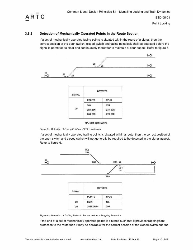
3.8.2 Detection of Mechanically Operated Points in the Route Section
If a set of mechanically operated facing points is situated within the route of a signal, then the
correct position of the open switch, closed switch and facing point lock shall be detected before the
signal is permitted to clear and continuously thereafter to maintain a clear aspect. Refer to figure 5.
Figure 5 – Detection of Facing Points and FPL’s in Routes
If a set of mechanically operated trailing points is situated within a route, then the correct position of
the open switch and closed switch will not generally be required to be detected in the signal aspect.
Refer to figure 6.
Figure 6 – Detection of Trailing Points in Routes and as a Trapping Protection
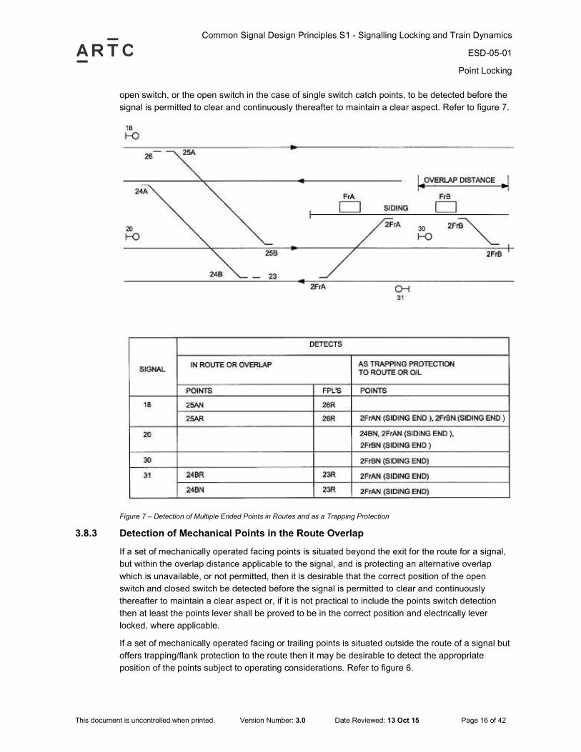
If the end of a set of mechanically operated points is situated such that it provides trapping/flank
protection to the route then it may be desirable for the correct position of the closed switch and the
Common Signal Design Principles S1 - Signalling Locking and Train Dynamics
ESD-05-01
Point Locking
This document is uncontrolled when printed. Version Number: 3.0 Date Reviewed: 13 Oct 15 Page 16 of 42
open switch, or the open switch in the case of single switch catch points, to be detected before the
signal is permitted to clear and continuously thereafter to maintain a clear aspect. Refer to figure 7.
Figure 7 – Detection of Multiple Ended Points in Routes and as a Trapping Protection
3.8.3 Detection of Mechanical Points in the Route Overlap
If a set of mechanically operated facing points is situated beyond the exit for the route for a signal,
but within the overlap distance applicable to the signal, and is protecting an alternative overlap
which is unavailable, or not permitted, then it is desirable that the correct position of the open
switch and closed switch be detected before the signal is permitted to clear and continuously
thereafter to maintain a clear aspect or, if it is not practical to include the points switch detection
then at least the points lever shall be proved to be in the correct position and electrically lever
locked, where applicable.
If a set of mechanically operated facing or trailing points is situated outside the route of a signal but
offers trapping/flank protection to the route then it may be desirable to detect the appropriate
position of the points subject to operating considerations. Refer to figure 6.
Common Signal Design Principles S1 - Signalling Locking and Train Dynamics
ESD-05-01
Point Locking
This document is uncontrolled when printed. Version Number: 3.0 Date Reviewed: 13 Oct 15 Page 17 of 42
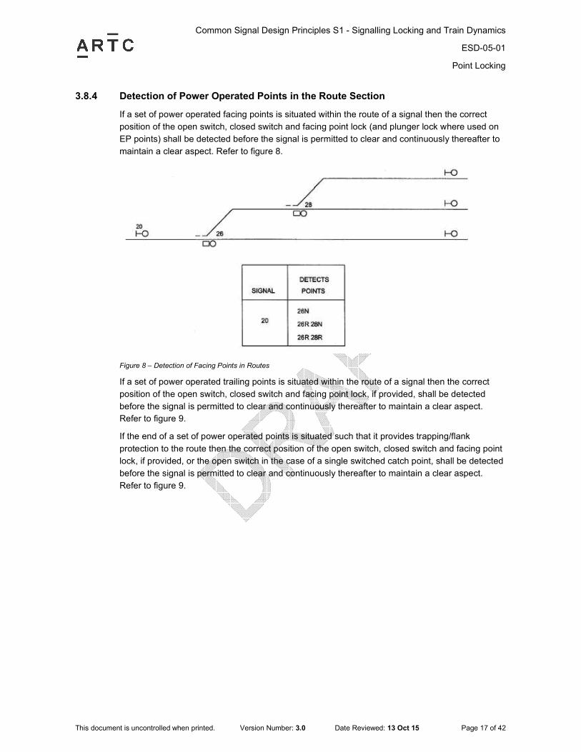
3.8.4 Detection of Power Operated Points in the Route Section
If a set of power operated facing points is situated within the route of a signal then the correct
position of the open switch, closed switch and facing point lock (and plunger lock where used on
EP points) shall be detected before the signal is permitted to clear and continuously thereafter to
maintain a clear aspect. Refer to figure 8.
Figure 8 – Detection of Facing Points in Routes
If a set of power operated trailing points is situated within the route of a signal then the correct
position of the open switch, closed switch and facing point lock, if provided, shall be detected
before the signal is permitted to clear and continuously thereafter to maintain a clear aspect.
Refer to figure 9.
If the end of a set of power operated points is situated such that it provides trapping/flank
protection to the route then the correct position of the open switch, closed switch and facing point
lock, if provided, or the open switch in the case of a single switched catch point, shall be detected
before the signal is permitted to clear and continuously thereafter to maintain a clear aspect.
Refer to figure 9.

Common Signal Design Principles S1 - Signalling Locking and Train Dynamics
ESD-05-01
Point Locking
This document is uncontrolled when printed. Version Number: 3.0 Date Reviewed: 13 Oct 15 Page 18 of 42
Figure 9 – Detection of Trailing Points in Routes and as a Trapping Protection
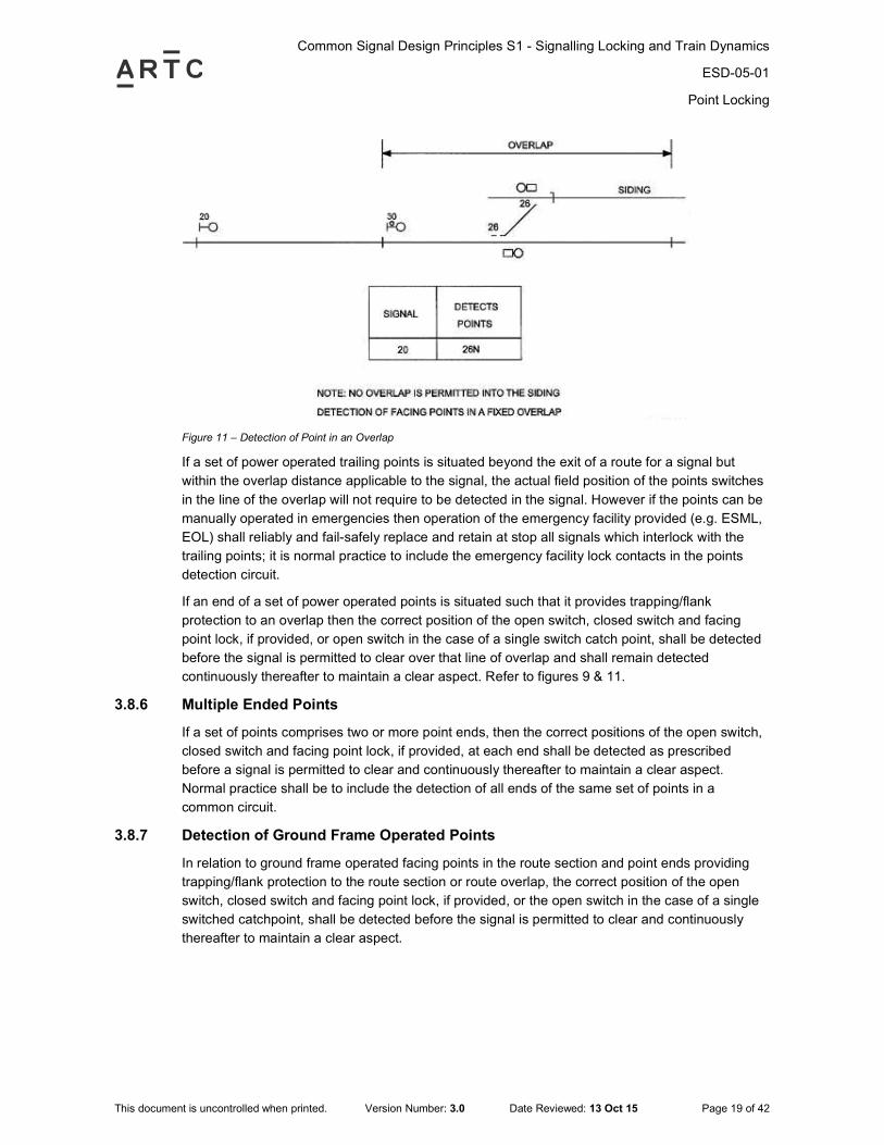
3.8.5 Detection of Power Operated Points in the Route Overlap
If a set of power operated facing points is situated beyond the exit of a route for a signal but
within the overlap distance applicable to the signal and is protecting an alternative overlap which
is unavailable, or not permitted, then the correct position of the open switch, closed switch and
facing point lock shall be detected before the signal is permitted to clear and continuously
thereafter to maintain a clear aspect. Refer to figures 10 & 11.
Figure 10 – Detection of Point in an Overlap
Common Signal Design Principles S1 - Signalling Locking and Train Dynamics
ESD-05-01
Point Locking
This document is uncontrolled when printed. Version Number: 3.0 Date Reviewed: 13 Oct 15 Page 19 of 42
Figure 11 – Detection of Point in an Overlap
If a set of power operated trailing points is situated beyond the exit of a route for a signal but
within the overlap distance applicable to the signal, the actual field position of the points switches
in the line of the overlap will not require to be detected in the signal. However if the points can be
manually operated in emergencies then operation of the emergency facility provided (e.g. ESML,
EOL) shall reliably and fail-safely replace and retain at stop all signals which interlock with the
trailing points; it is normal practice to include the emergency facility lock contacts in the points
detection circuit.
If an end of a set of power operated points is situated such that it provides trapping/flank
protection to an overlap then the correct position of the open switch, closed switch and facing
point lock, if provided, or open switch in the case of a single switch catch point, shall be detected
before the signal is permitted to clear over that line of overlap and shall remain detected
continuously thereafter to maintain a clear aspect. Refer to figures 9 & 11.
3.8.6 Multiple Ended Points
If a set of points comprises two or more point ends, then the correct positions of the open switch,
closed switch and facing point lock, if provided, at each end shall be detected as prescribed
before a signal is permitted to clear and continuously thereafter to maintain a clear aspect.
Normal practice shall be to include the detection of all ends of the same set of points in a
common circuit.
3.8.7 Detection of Ground Frame Operated Points
In relation to ground frame operated facing points in the route section and point ends providing
trapping/flank protection to the route section or route overlap, the correct position of the open
switch, closed switch and facing point lock, if provided, or the open switch in the case of a single
switched catchpoint, shall be detected before the signal is permitted to clear and continuously
thereafter to maintain a clear aspect.
Common Signal Design Principles S1 - Signalling Locking and Train Dynamics
ESD-05-01
Point Locking
This document is uncontrolled when printed. Version Number: 3.0 Date Reviewed: 13 Oct 15 Page 20 of 42
3.9 Track Circuit Locking of Points
3.9.1 Purpose
Track locking is provided over points to ensure they are held in position for the passage of a train
once the direct route to point locking has been normalised and the train is between the points and
the signal leading over them.
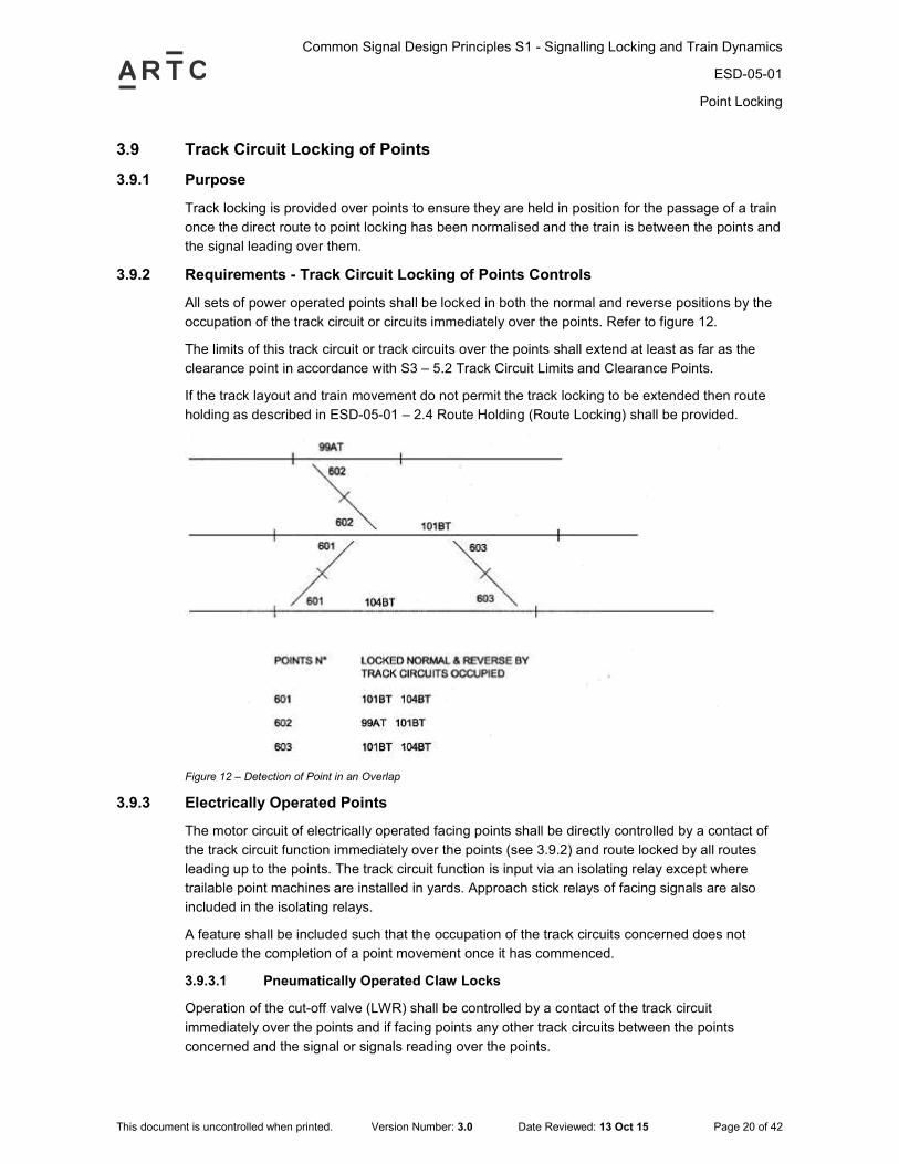
3.9.2 Requirements - Track Circuit Locking of Points Controls
All sets of power operated points shall be locked in both the normal and reverse positions by the
occupation of the track circuit or circuits immediately over the points. Refer to figure 12.
The limits of this track circuit or track circuits over the points shall extend at least as far as the
clearance point in accordance with S3 – 5.2 Track Circuit Limits and Clearance Points.
If the track layout and train movement do not permit the track locking to be extended then route
holding as described in ESD-05-01 – 2.4 Route Holding (Route Locking) shall be provided.
Figure 12 – Detection of Point in an Overlap
3.9.3 Electrically Operated Points
The motor circuit of electrically operated facing points shall be directly controlled by a contact of
the track circuit function immediately over the points (see 3.9.2) and route locked by all routes
leading up to the points. The track circuit function is input via an isolating relay except where
trailable point machines are installed in yards. Approach stick relays of facing signals are also
included in the isolating relays.
A feature shall be included such that the occupation of the track circuits concerned does not
preclude the completion of a point movement once it has commenced.
3.9.3.1 Pneumatically Operated Claw Locks
Operation of the cut-off valve (LWR) shall be controlled by a contact of the track circuit
immediately over the points and if facing points any other track circuits between the points
concerned and the signal or signals reading over the points.
Common Signal Design Principles S1 - Signalling Locking and Train Dynamics
ESD-05-01
Point Locking
This document is uncontrolled when printed. Version Number: 3.0 Date Reviewed: 13 Oct 15 Page 21 of 42
3.9.4 Control Tables
The requirements for the direct track locking of point operating mechanisms shall be in
accordance with the Control Tables concerned.
Track circuits over points shall be high voltage impulse type. However, other track circuit types
may be used where it is demonstrated that there are no issues with the reliability of operation.
Common Signal Design Principles S1 - Signalling Locking and Train Dynamics
ESD-05-01
Headway
This document is uncontrolled when printed. Version Number: 3.0 Date Reviewed: 13 Oct 15 Page 22 of 42
4 Headway
4.1 Headway Concepts and Definitions
The headway on any section of railway line is a measure of the capacity to pass trains through
the section.
Headway is defined as the time interval between successive trains running at the line speed on
clear signal aspects.
Headway is expressed in minutes and perhaps seconds rather than the number of trains passing
over a line during each hourly interval.
The spacing of signals on a section of line may not achieve a consistent headway due to other
factors. The headway for the section of line is then based on the worst case headway of the
individual signals.
Headway may be stated for trains of a specific type or performance.
4.2 Signal Spacing
As headway considerations become critical to the performance of train services then it is
necessary to provide a system of evenly time-spaced signals having regard to the effect of line
speed, braking and gradient. Other operating factors such as station dwell time, freight train
acceleration/deceleration and actual performance on the track (gradient and curves) will also
affect headway considerations. Train simulation may be required to determine these effects.
Signal spacing is defined as the distance between two signals. It is often evaluated for successive
signals provided to achieve a particular headway for a line.
4.3 Sighting Point & Distance
Adequate signal sighting point is essential if the drivers of trains are to be allowed to take the
maximum advantage of the signal aspects ahead of them. Poor sighting can have a detrimental
effect on headways in practice.
The sighting point is the point in rear of a signal at which the driver of a train is first able to view
the signal.
The sighting distance is the distance between the sighting point and the signal to which it applies.
The distance between the sighting point and the signal is provided to allow the driver to firstly
observe the signal and then to be in a position to respond to the aspect displayed. The time
permitted for sighting a signal shall normally be a minimum of 8 seconds. In exceptional situations
this may be reduced to an absolute minimum of 6 seconds. For further details see ESC-04-01
Signal Sighting and Position.
The actual Sighting Distance may vary depending upon the approach speed of the train. When
the line speed or train approach speed is increased, the Signal Sighting distance shall be
reviewed.
The Signal Sighting Distance shall not be considered as part of the train braking distance when
determining the spacing of signals.
Common Signal Design Principles S1 - Signalling Locking and Train Dynamics
ESD-05-01
Headway
This document is uncontrolled when printed. Version Number: 3.0 Date Reviewed: 13 Oct 15 Page 23 of 42
4.4 Distance between Running Signals
4.4.1 Minimum Distance between Running Signal Aspects
The Braking Distance of trains is a crucial factor in determining the position of signals and
aspects to be displayed. Braking Distances and permitted line speeds will vary between different
classes of trains. For a section of track the signal design shall account for all classes of trains but
may be determined by the limiting performance of the line speed and braking distance of one of
the classes of trains. This must take into account the track infrastructure factors of line speed,
gradient and curvature.
The “longest braking distance” shall be the service braking distance of the train that takes the
longest distance to stop or nominate target speed from its maximum allowable and attainable
speed at that particular brake application location. Where the attainable speed is significantly
below the line speed then this should only be used if there are other controls or mitigations to
ensure that future trains do not exceed this design speed.
The minimum distance between a signal showing a first warning aspect and the stop signal to
which it applies shall not be less than the respective “longest braking distance”. This distance
shall be determined in accordance with ESD-05-01 – 5.2 Braking Distance in Signalling Systems
The minimum distance between a signal showing the first warning aspect and a points turnout to
which it applies shall not be less than the “longest braking distance” to reduce to the restricted
speed required for the points turnout.
The minimum distance between a signal showing the first warning aspect and a subsidiary signal
showing a proceed aspect shall be the “longest braking distance” to reduce to the restricted
speed required by the subsidiary signal proceed aspect where such restricted speed is
applicable.
4.4.2 Maximum Distance between 3 Aspect Running Signals
The distance between 3 aspect running signals shall generally be limited to 4,000m and
exceptionally to an absolute limit of 4,500m.
If the distance between two successive running signals is greater than 4km and more than 2
times the service braking distance then the sighting distance of the second signal shall be greater
than the minimum sighting distance shall be in accordance with ESC-04-01 Signals Sighting and
Position and SDS 01 Signals – 1.12 Positioning and Sighting of Signals. The overlap distance for
the first signal beyond the second signal should be greater than the normal minimum overlap
distance shall be in accordance with ESD-05-01 – 6.2 Overlaps for Colour Light Running Signals,
such that the sighting distance and the overlap distance together are greater than their combined
minimum distances to an extent commensurate with the greater distance between the signals.
This only applies to double track with automatic and control signals.
Common Signal Design Principles S1 - Signalling Locking and Train Dynamics
ESD-05-01
Braking Distance Concepts and Definitions
This document is uncontrolled when printed. Version Number: 3.0 Date Reviewed: 13 Oct 15 Page 24 of 42
5 Braking Distance Concepts and Definitions
5.1 Definitions
5.1.1 Braking Distance – Concept
Braking Distances for trains can be relatively long due to their significant mass, speed, braking
characteristics, and the track gradients.
Consequently the Braking Distances become a critical consideration when determining the
position of the first warning aspect with respect to the stop signal to which it applies, and
especially so when trains with different Braking Distances operate over the same line.
5.1.2 Braking Distance – Definition
Braking Distance is the distance travelled by a train between the point at which the driver initiates
a brake application and the point at which the train eventually comes to rest.
5.1.3 Service Braking Distance – Definition
Service Braking Distance is fundamental in determining the minimum distance between the first
warning aspect given to a driver and the stop signal to which it applies.
5.1.4 Emergency Braking Distance – Definition
Emergency Braking Distance is the braking distance for a train when it has been subjected to an
“emergency” brake application.
Emergency Braking Distance may be used in determining the minimum overlap distance to be
provided beyond a stop signal.
Notes: The Emergency Brake can be initiated independently of the Service Brake for example by
release of the “dead mans lever” or by a train stop mechanism where provided.
Emergency Braking Distance is not necessarily less than the Service Braking Distance and is
greater for some types of trains.
5.2 Braking Distance in Signalling Systems
5.2.1 Determination of Braking Distance
The Braking Distance for each type of train running on a particular line may be obtained from
theoretical calculation or from dynamic tests performed on the trains themselves or result from a
mixture of both sources of information.
The approved Brake Tables shall be used to determine signal design requirements.
Either way, many factors influencing this predetermined Braking Distance. The Brake Tables
have included consideration of:
Common Signal Design Principles S1 - Signalling Locking and Train Dynamics
ESD-05-01
Braking Distance Concepts and Definitions
This document is uncontrolled when printed. Version Number: 3.0 Date Reviewed: 13 Oct 15 Page 25 of 42
• the speed of the train when the brake application was initiated
• the fundamental rate of braking which can be achieved
• the effects of the braking system reaction time
• the number of brakes which may be cut out
• the acceptable amount of wear and tear on braking performance
• the effect of rising or falling gradients
• % contingency.
From the above two sets of Braking Tables can be produced for each type of train, one for
Service Braking and one for Emergency Braking.
5.2.2 Service Braking (SB) Curves
The Service Braking curves to be used in conjunction with this Principle shall be the curves
nominated in the standard ESD-32-01 Signalling Rollingstock Interface.
When designing a signalling system, the signal spacing shall be determined so as to enable the
longest braking distance train, travelling at its maximum allowable and attainable speed, applying
service braking at the warning signal to come to a stand at the signal. The sighting distance of the
warning signal shall not be included in the determination of the minimum signal spacing for
braking when designing the system.
5.2.3 Determination of Longest Braking Distance
The longest (service) braking distance required in any particular section of a running line shall be
determined from the appropriate Service Braking Tables have regard to:
• the types of trains running over the particular section of line
• the maximum speed permitted (line speed) for each type of train. Note that it is the line
speed approaching the first warning signal rather than the line speed between the warning
signal and the stop signal which is most relevant.
• the service speed of each type of train in the particular section of line. (For example, some
types of freight train are limited to a maximum speed irrespective of line speed and in some
situations trains may not be able to always attain line speed)
• the gradient on the particular section of line, in particular the gradient approaching the
warning signal and between the warning signal and the stop signal. Where there is a change
in gradient, then the braking distance shall be calculated by incrementally determining the
speed reduction for each section of gradient. Where there is a long train then the point of the
centre of mass of the train shall be used to determine the gradient applicable for
calculations.
• the present speed restriction, if any, applicable to the particular section of line.
Care must be exercised in accurately identifying the “worst” braked trains running over the
particular section of line for the purpose of determining the longest (service) braking distance
correctly.
Subsequent to power failure affecting the area controlled by an interlocking or the interlocking
itself, the track circuit release of approach locking shall be suppressed for a time which is not less
than the longest approach locking time release for the interlocking.
Common Signal Design Principles S1 - Signalling Locking and Train Dynamics
ESD-05-01
Overlaps Concepts and Definitions
This document is uncontrolled when printed. Version Number: 3.0 Date Reviewed: 13 Oct 15 Page 26 of 42
6 Overlaps Concepts and Definitions
6.1 Overlap – Definition
An overlap is the section of track immediately in advance of a stop signal which must be
unoccupied and free before the stop signal next in rear is permitted to show a proceed indication.
The overlap distance is the length of the section of track which forms the overlap and is
measured from the Stop signal to a predetermined clearing point in advance.
Where provided, the purpose of an overlap is to ensure a margin of safety beyond a stop signal
by establishing a predetermined separation distance between two trains. This is to allow for
slippery rails or a misjudgement of the final brake application by a driver intending to stop at a
signal. The margin of safety is a predetermined separation distance between two trains and may
be prescribed under these Principles:
• Historical precedents and experimental data
• Maximum Line Speed
• Permanent Speed Restrictions
• Service Speed
• Service Braking Tables
• Emergency Braking Tables
• Impact of gradient
• Emergency Brake Tripping System
• Automatic Train Protection System
• Provision of conditional caution aspect clearance of signals.
When there is enforcement of train braking, then the overall distance is determined dynamically
using the relevant train braking tables.
Opposing moving trains cannot share a common overlap except as detailed below in 6.2.4.
It is not ARTC policy to provide enforcement of train braking by automatic train protection
systems e.g. train stops. However, where these are provided as legacy systems or otherwise
and trains are correspondingly fitted, then the overlap distance is the emergency braking distance
for the fitted trains.
6.2 Overlaps for Colour Light Running Signals
6.2.1 Provision of an Overlap
If a running signal is capable of showing an unconditional warning aspect then an overlap shall be
provided immediately beyond the stop signal to which the warning aspect applies.
6.2.2 Overlap Distance
The nominal length of the overlap to be provided shall not be less than the minimum distances
shown below:

Common Signal Design Principles S1 - Signalling Locking and Train Dynamics
ESD-05-01
Overlaps Concepts and Definitions
This document is uncontrolled when printed. Version Number: 3.0 Date Reviewed: 13 Oct 15 Page 27 of 42
• Low speed subsidiary for route signalling or conditional cleared running signals, 100m
• Running signals, 200m
• Running signals with a line speed greater than 80kph, 300m.
If the train density is such that the headway is less than 10 minutes, then the overlap distance is
increased by 100m.
6.2.3 Variations to Overlap Distances
If the grade on a particular section of line is greater than 1 in 100 falling, then the overlap distance
shall be increased for that speed range by not less than 100m.
If a block joint already exists or is to be provided for other purposes and could also be used as an
overlap block joint without adversely affecting the line headway then the overlap distance may be
increased to avoid the provision of a separate overlap track circuit.
If the line headway is adversely affected by the nominal overlap distance then a reduction in the
overlap distance should be considered based on the appropriate factors presented under ESD-
05-01 – 6 Overlap Concept and Definition.
Where train speeds are permanently restricted due to them departing yards or negotiating
turnouts or junctions, then the overlaps beyond the signal may be reduced to 90m where the
speed approaching the signal is restricted to 15kph and to 150m where the speed is restricted to
25kph, or reduced to the longest braking distance, if less.
If a running signal is more than 4km and more than 2 times service braking distance from the next
signal, then the overlap distance for that running signal beyond the next signal shall be
commensurably greater than the normal minimum overlap distance.
If a line is freight only then, consideration may be given to the reduction in the length of overlaps,
based on a Risk Assessment for the operation of the line.
This Principle addresses the requirements for the provision of overlaps on single lines and in
crossing loops in CTC colour light territory.
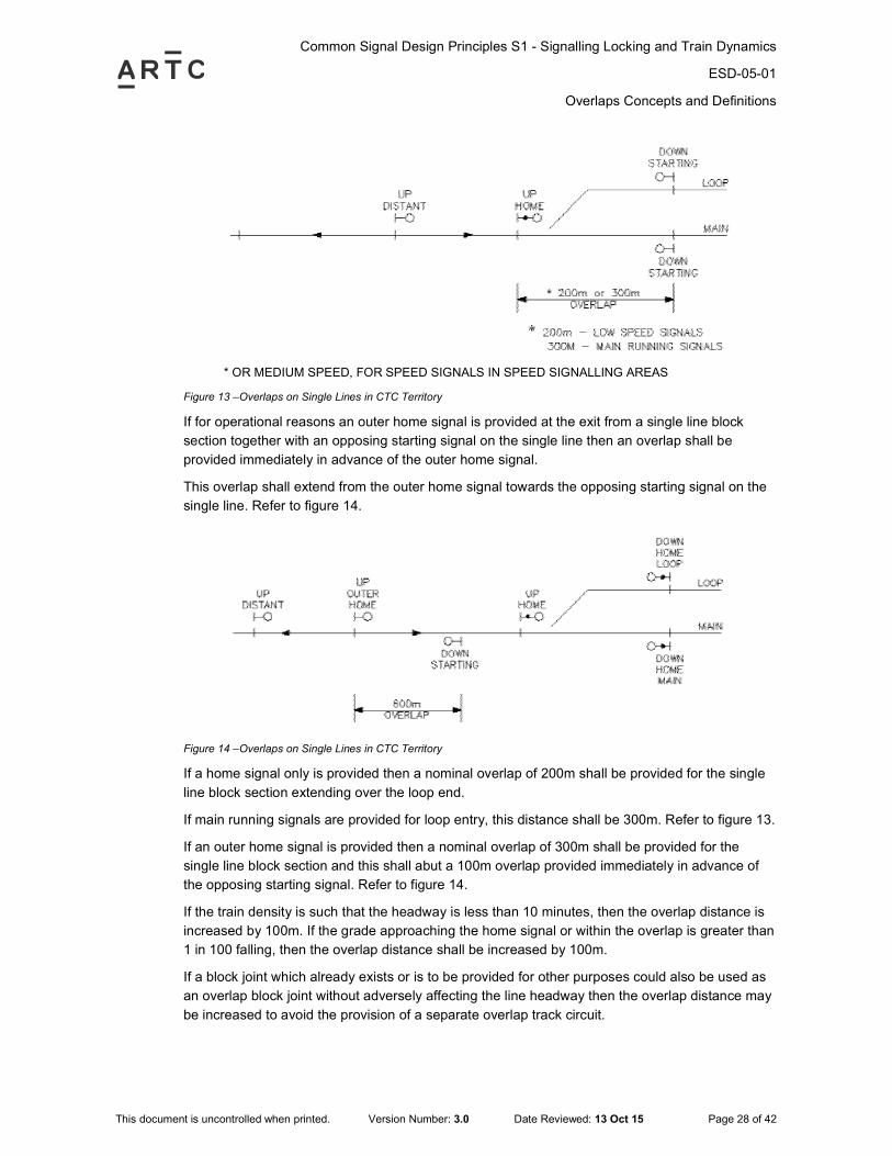
6.2.4 Provision of an Overlap on a Single Line in CTC Territory
An overlap shall be provided at the exit from a single line block section immediately in advance of
the home signal.
This overlap shall extend from the home signal as far as the opposing main and loop starting
signals controlling the entrance to the single line block section and shall incorporate loop and
flank protection. Refer to figure 13.
Common Signal Design Principles S1 - Signalling Locking and Train Dynamics
ESD-05-01
Overlaps Concepts and Definitions
This document is uncontrolled when printed. Version Number: 3.0 Date Reviewed: 13 Oct 15 Page 28 of 42
* OR MEDIUM SPEED, FOR SPEED SIGNALS IN SPEED SIGNALLING AREAS
Figure 13 –Overlaps on Single Lines in CTC Territory
If for operational reasons an outer home signal is provided at the exit from a single line block
section together with an opposing starting signal on the single line then an overlap shall be
provided immediately in advance of the outer home signal.
This overlap shall extend from the outer home signal towards the opposing starting signal on the
single line. Refer to figure 14.
Figure 14 –Overlaps on Single Lines in CTC Territory
If a home signal only is provided then a nominal overlap of 200m shall be provided for the single
line block section extending over the loop end.
If main running signals are provided for loop entry, this distance shall be 300m. Refer to figure 13.
If an outer home signal is provided then a nominal overlap of 300m shall be provided for the
single line block section and this shall abut a 100m overlap provided immediately in advance of
the opposing starting signal. Refer to figure 14.
If the train density is such that the headway is less than 10 minutes, then the overlap distance is
increased by 100m. If the grade approaching the home signal or within the overlap is greater than
1 in 100 falling, then the overlap distance shall be increased by 100m.
If a block joint which already exists or is to be provided for other purposes could also be used as
an overlap block joint without adversely affecting the line headway then the overlap distance may
be increased to avoid the provision of a separate overlap track circuit.

Common Signal Design Principles S1 - Signalling Locking and Train Dynamics
ESD-05-01
Overlaps Concepts and Definitions
This document is uncontrolled when printed. Version Number: 3.0 Date Reviewed: 13 Oct 15 Page 29 of 42
6.2.5 Provision of Overlaps at a Crossing Loop
The home signal shall be provided with an overlap immediately in advance of the main and loop
starting signals into the single line block section in advance.
This overlap shall extend from the main or loop starting signal into the single line block section in
advance as far as the opposing home signal. Refer to figure 15.
Figure 15 –Overlaps on Crossing Loops in CTC Territory
If an outer home signal is provided then an overlap shall be provided for the caution aspect.
This overlap shall extend from the home signal to the main or loop signals leading into the single
line block section in advance. Refer to figure 16a.
Figure 16a –Overlaps on Crossing Loops in CTC Territory
At CTC loops using a low speed subsidiary for entry, the distance between the loop and main
starting signals and the home signal shall be 200m. Where main running aspects are used for
entry, this distance shall be 300m. The points shall be set to deflect any conflicting movement.
The nominal overlap distance for an outer home signal shall not be less than that required under
ESD-05-01 - 6.2.2 Overlap Distances and not greater than the distance to the main and loop
signals leading into the section in advance.
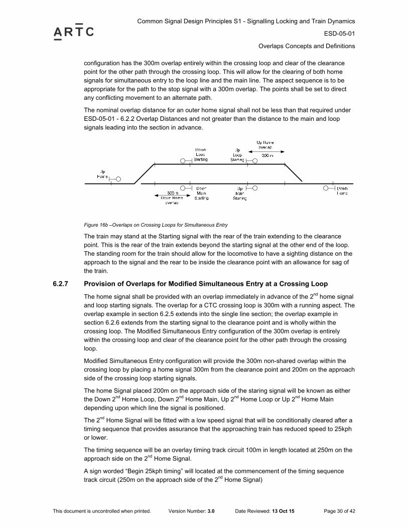
6.2.6 Provision of Overlaps for Simultaneous Entry at a Crossing Loop
The home signal shall be provided with an overlap immediately in advance of the main and loop
starting signals. As detailed above, the overlap for a CTC crossing loop is 300m with a running
aspect. This overlap in the above examples extends into the single line section. The following
Common Signal Design Principles S1 - Signalling Locking and Train Dynamics
ESD-05-01
Overlaps Concepts and Definitions
This document is uncontrolled when printed. Version Number: 3.0 Date Reviewed: 13 Oct 15 Page 30 of 42
configuration has the 300m overlap entirely within the crossing loop and clear of the clearance
point for the other path through the crossing loop. This will allow for the clearing of both home
signals for simultaneous entry to the loop line and the main line. The aspect sequence is to be
appropriate for the path to the stop signal with a 300m overlap. The points shall be set to direct
any conflicting movement to an alternate path.
The nominal overlap distance for an outer home signal shall not be less than that required under
ESD-05-01 - 6.2.2 Overlap Distances and not greater than the distance to the main and loop
signals leading into the section in advance.
Figure 16b –Overlaps on Crossing Loops for Simultaneous Entry
The train may stand at the Starting signal with the rear of the train extending to the clearance
point. This is the rear of the train extends beyond the starting signal at the other end of the loop.
The standing room for the train should allow for the locomotive to have a sighting distance on the
approach to the signal and the rear to be inside the clearance point with an allowance for sag of
the train.
6.2.7 Provision of Overlaps for Modified Simultaneous Entry at a Crossing Loop
The home signal shall be provided with an overlap immediately in advance of the 2nd
home signal
and loop starting signals. The overlap for a CTC crossing loop is 300m with a running aspect. The
overlap example in section 6.2.5 extends into the single line section; the overlap example in
section 6.2.6 extends from the starting signal to the clearance point and is wholly within the
crossing loop. The Modified Simultaneous Entry configuration of the 300m overlap is entirely
within the crossing loop and clear of the clearance point for the other path through the crossing
loop.
Modified Simultaneous Entry configuration will provide the 300m non-shared overlap within the
crossing loop by placing a home signal 300m from the clearance point and 200m on the approach
side of the crossing loop starting signals.
The home Signal placed 200m on the approach side of the staring signal will be known as either
the Down 2nd
Home Loop, Down 2nd
Home Main, Up 2nd
Home Loop or Up 2nd
Home Main
depending upon which line the signal is positioned.
The 2nd
Home Signal will be fitted with a low speed signal that will be conditionally cleared after a
timing sequence that provides assurance that the approaching train has reduced speed to 25kph
or lower.
The timing sequence will be an overlay timing track circuit 100m in length located at 250m on the
approach side on the 2nd
Home Signal.
A sign worded “Begin 25kph timing” will located at the commencement of the timing sequence
track circuit (250m on the approach side of the 2nd
Home Signal)
Common Signal Design Principles S1 - Signalling Locking and Train Dynamics
ESD-05-01
Overlaps Concepts and Definitions
This document is uncontrolled when printed. Version Number: 3.0 Date Reviewed: 13 Oct 15 Page 31 of 42
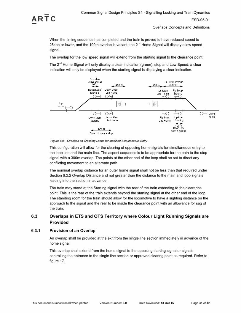
When the timing sequence has completed and the train is proved to have reduced speed to
25kph or lower, and the 100m overlap is vacant, the 2nd
Home Signal will display a low speed
signal.
The overlap for the low speed signal will extend from the starting signal to the clearance point.
The 2nd
Home Signal will only display a clear indication (green), stop and Low Speed; a clear
indication will only be displayed when the starting signal is displaying a clear indication.
Be
gin
25
Kp
h
Tim
ing B
eg
in
25
Kp
h
Tim
ing
Figure 16c –Overlaps on Crossing Loops for Modified Simultaneous Entry
This configuration will allow for the clearing of opposing home signals for simultaneous entry to
the loop line and the main line. The aspect sequence is to be appropriate for the path to the stop
signal with a 300m overlap. The points at the other end of the loop shall be set to direct any
conflicting movement to an alternate path.
The nominal overlap distance for an outer home signal shall not be less than that required under
Section 6.2.2 Overlap Distance and not greater than the distance to the main and loop signals
leading into the section in advance.
The train may stand at the Starting signal with the rear of the train extending to the clearance
point. This is the rear of the train extends beyond the starting signal at the other end of the loop.
The standing room for the train should allow for the locomotive to have a sighting distance on the
approach to the signal and the rear to be inside the clearance point with an allowance for sag of
the train.
6.3 Overlaps in ETS and OTS Territory where Colour Light Running Signals are
Provided
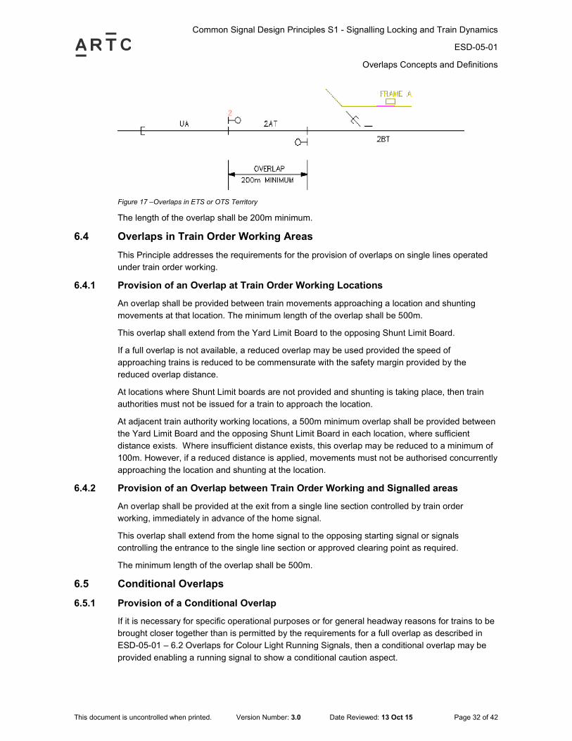
6.3.1 Provision of an Overlap
An overlap shall be provided at the exit from the single line section immediately in advance of the
home signal.
This overlap shall extend from the home signal to the opposing starting signal or signals
controlling the entrance to the single line section or approved clearing point as required. Refer to
figure 17.
Common Signal Design Principles S1 - Signalling Locking and Train Dynamics
ESD-05-01
Overlaps Concepts and Definitions
This document is uncontrolled when printed. Version Number: 3.0 Date Reviewed: 13 Oct 15 Page 32 of 42
Figure 17 –Overlaps in ETS or OTS Territory
The length of the overlap shall be 200m minimum.
6.4 Overlaps in Train Order Working Areas
This Principle addresses the requirements for the provision of overlaps on single lines operated
under train order working.
6.4.1 Provision of an Overlap at Train Order Working Locations
An overlap shall be provided between train movements approaching a location and shunting
movements at that location. The minimum length of the overlap shall be 500m.
This overlap shall extend from the Yard Limit Board to the opposing Shunt Limit Board.
If a full overlap is not available, a reduced overlap may be used provided the speed of
approaching trains is reduced to be commensurate with the safety margin provided by the
reduced overlap distance.
At locations where Shunt Limit boards are not provided and shunting is taking place, then train
authorities must not be issued for a train to approach the location.
At adjacent train authority working locations, a 500m minimum overlap shall be provided between
the Yard Limit Board and the opposing Shunt Limit Board in each location, where sufficient
distance exists. Where insufficient distance exists, this overlap may be reduced to a minimum of
100m. However, if a reduced distance is applied, movements must not be authorised concurrently
approaching the location and shunting at the location.
6.4.2 Provision of an Overlap between Train Order Working and Signalled areas
An overlap shall be provided at the exit from a single line section controlled by train order
working, immediately in advance of the home signal.
This overlap shall extend from the home signal to the opposing starting signal or signals
controlling the entrance to the single line section or approved clearing point as required.
The minimum length of the overlap shall be 500m.
6.5 Conditional Overlaps
6.5.1 Provision of a Conditional Overlap
If it is necessary for specific operational purposes or for general headway reasons for trains to be
brought closer together than is permitted by the requirements for a full overlap as described in
ESD-05-01 – 6.2 Overlaps for Colour Light Running Signals, then a conditional overlap may be
provided enabling a running signal to show a conditional caution aspect.
Common Signal Design Principles S1 - Signalling Locking and Train Dynamics
ESD-05-01
Overlaps Concepts and Definitions
This document is uncontrolled when printed. Version Number: 3.0 Date Reviewed: 13 Oct 15 Page 33 of 42
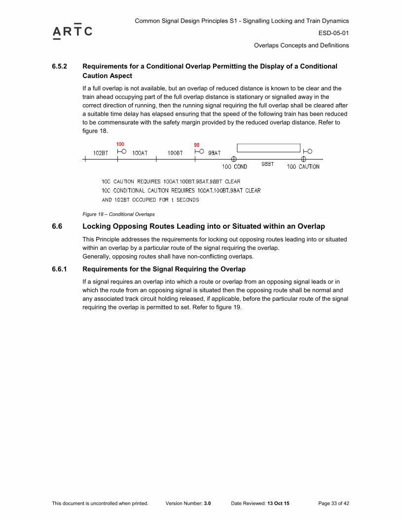
6.5.2 Requirements for a Conditional Overlap Permitting the Display of a Conditional
Caution Aspect
If a full overlap is not available, but an overlap of reduced distance is known to be clear and the
train ahead occupying part of the full overlap distance is stationary or signalled away in the
correct direction of running, then the running signal requiring the full overlap shall be cleared after
a suitable time delay has elapsed ensuring that the speed of the following train has been reduced
to be commensurate with the safety margin provided by the reduced overlap distance. Refer to
figure 18.
Figure 18 – Conditional Overlaps
6.6 Locking Opposing Routes Leading into or Situated within an Overlap
This Principle addresses the requirements for locking out opposing routes leading into or situated
within an overlap by a particular route of the signal requiring the overlap.
Generally, opposing routes shall have non-conflicting overlaps.
6.6.1 Requirements for the Signal Requiring the Overlap
If a signal requires an overlap into which a route or overlap from an opposing signal leads or in
which the route from an opposing signal is situated then the opposing route shall be normal and
any associated track circuit holding released, if applicable, before the particular route of the signal
requiring the overlap is permitted to set. Refer to figure 19.
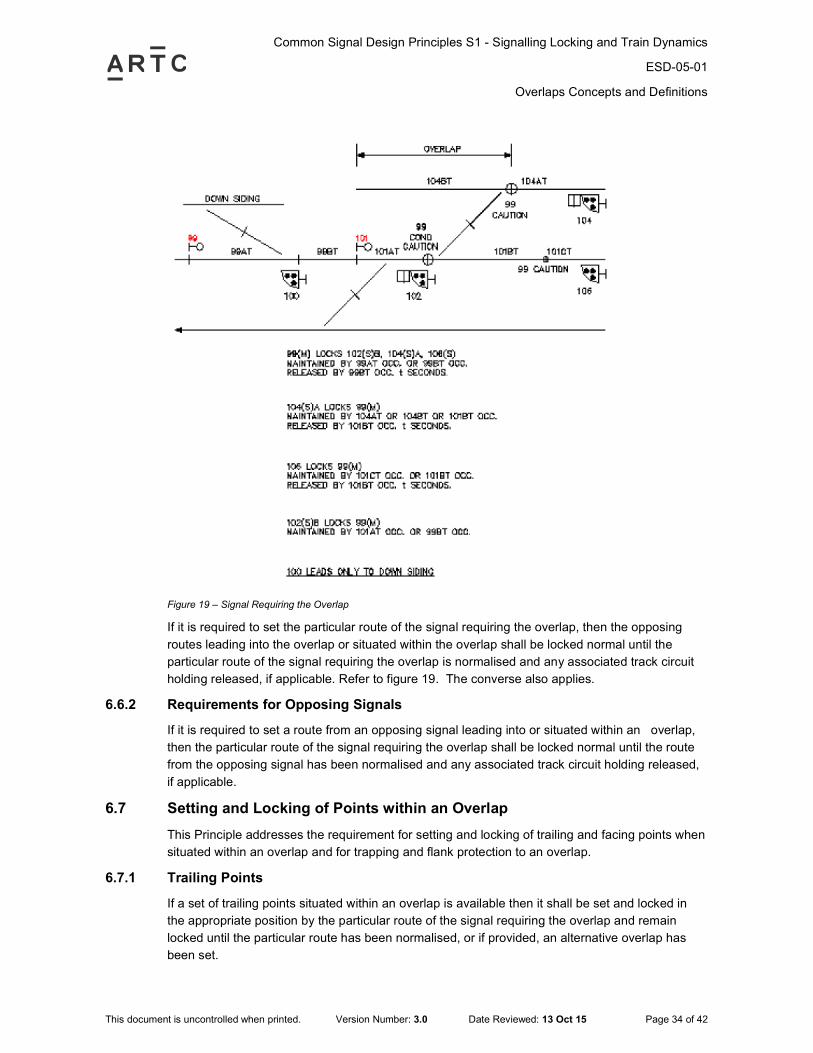
Common Signal Design Principles S1 - Signalling Locking and Train Dynamics
ESD-05-01
Overlaps Concepts and Definitions
This document is uncontrolled when printed. Version Number: 3.0 Date Reviewed: 13 Oct 15 Page 34 of 42
Figure 19 – Signal Requiring the Overlap
If it is required to set the particular route of the signal requiring the overlap, then the opposing
routes leading into the overlap or situated within the overlap shall be locked normal until the
particular route of the signal requiring the overlap is normalised and any associated track circuit
holding released, if applicable. Refer to figure 19. The converse also applies.
6.6.2 Requirements for Opposing Signals
If it is required to set a route from an opposing signal leading into or situated within an overlap,
then the particular route of the signal requiring the overlap shall be locked normal until the route
from the opposing signal has been normalised and any associated track circuit holding released,
if applicable.
6.7 Setting and Locking of Points within an Overlap
This Principle addresses the requirement for setting and locking of trailing and facing points when
situated within an overlap and for trapping and flank protection to an overlap.
6.7.1 Trailing Points
If a set of trailing points situated within an overlap is available then it shall be set and locked in
the appropriate position by the particular route of the signal requiring the overlap and remain
locked until the particular route has been normalised, or if provided, an alternative overlap has
been set.
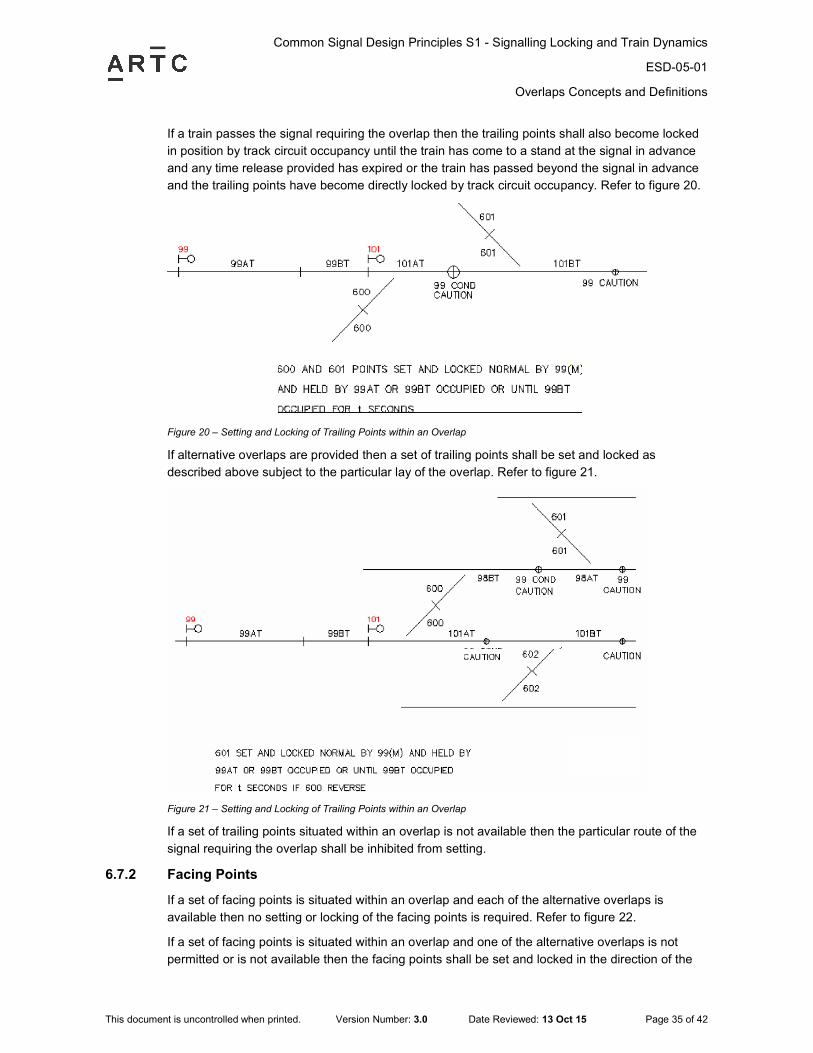
Common Signal Design Principles S1 - Signalling Locking and Train Dynamics
ESD-05-01
Overlaps Concepts and Definitions
This document is uncontrolled when printed. Version Number: 3.0 Date Reviewed: 13 Oct 15 Page 35 of 42
If a train passes the signal requiring the overlap then the trailing points shall also become locked
in position by track circuit occupancy until the train has come to a stand at the signal in advance
and any time release provided has expired or the train has passed beyond the signal in advance
and the trailing points have become directly locked by track circuit occupancy. Refer to figure 20.
Figure 20 – Setting and Locking of Trailing Points within an Overlap
If alternative overlaps are provided then a set of trailing points shall be set and locked as
described above subject to the particular lay of the overlap. Refer to figure 21.
Figure 21 – Setting and Locking of Trailing Points within an Overlap
If a set of trailing points situated within an overlap is not available then the particular route of the
signal requiring the overlap shall be inhibited from setting.
6.7.2 Facing Points
If a set of facing points is situated within an overlap and each of the alternative overlaps is
available then no setting or locking of the facing points is required. Refer to figure 22.
If a set of facing points is situated within an overlap and one of the alternative overlaps is not
permitted or is not available then the facing points shall be set and locked in the direction of the
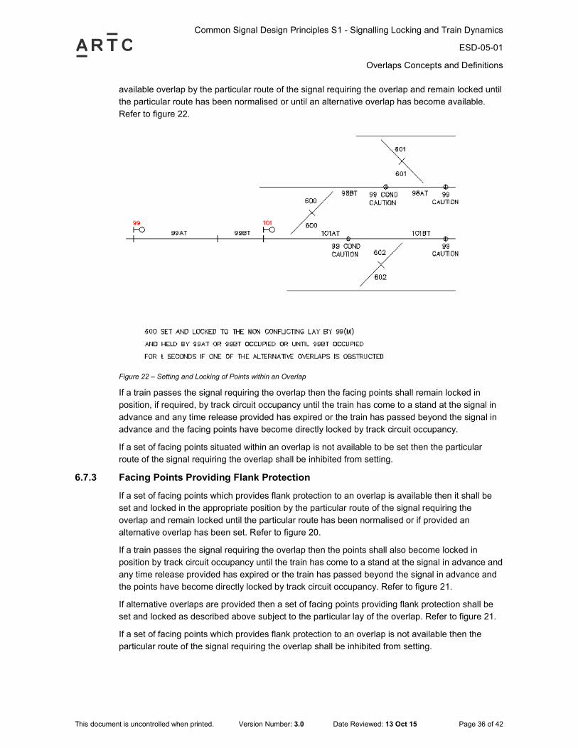
Common Signal Design Principles S1 - Signalling Locking and Train Dynamics
ESD-05-01
Overlaps Concepts and Definitions
This document is uncontrolled when printed. Version Number: 3.0 Date Reviewed: 13 Oct 15 Page 36 of 42
available overlap by the particular route of the signal requiring the overlap and remain locked until
the particular route has been normalised or until an alternative overlap has become available.
Refer to figure 22.
Figure 22 – Setting and Locking of Points within an Overlap
If a train passes the signal requiring the overlap then the facing points shall remain locked in
position, if required, by track circuit occupancy until the train has come to a stand at the signal in
advance and any time release provided has expired or the train has passed beyond the signal in
advance and the facing points have become directly locked by track circuit occupancy.
If a set of facing points situated within an overlap is not available to be set then the particular
route of the signal requiring the overlap shall be inhibited from setting.
6.7.3 Facing Points Providing Flank Protection
If a set of facing points which provides flank protection to an overlap is available then it shall be
set and locked in the appropriate position by the particular route of the signal requiring the
overlap and remain locked until the particular route has been normalised or if provided an
alternative overlap has been set. Refer to figure 20.
If a train passes the signal requiring the overlap then the points shall also become locked in
position by track circuit occupancy until the train has come to a stand at the signal in advance and
any time release provided has expired or the train has passed beyond the signal in advance and
the points have become directly locked by track circuit occupancy. Refer to figure 21.
If alternative overlaps are provided then a set of facing points providing flank protection shall be
set and locked as described above subject to the particular lay of the overlap. Refer to figure 21.
If a set of facing points which provides flank protection to an overlap is not available then the
particular route of the signal requiring the overlap shall be inhibited from setting.
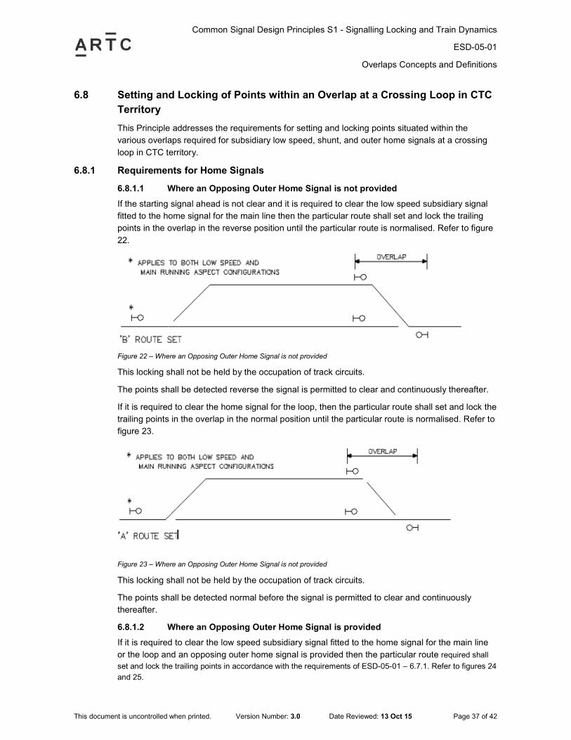
Common Signal Design Principles S1 - Signalling Locking and Train Dynamics
ESD-05-01
Overlaps Concepts and Definitions
This document is uncontrolled when printed. Version Number: 3.0 Date Reviewed: 13 Oct 15 Page 37 of 42
6.8 Setting and Locking of Points within an Overlap at a Crossing Loop in CTC
Territory
This Principle addresses the requirements for setting and locking points situated within the
various overlaps required for subsidiary low speed, shunt, and outer home signals at a crossing
loop in CTC territory.
6.8.1 Requirements for Home Signals
6.8.1.1 Where an Opposing Outer Home Signal is not provided
If the starting signal ahead is not clear and it is required to clear the low speed subsidiary signal
fitted to the home signal for the main line then the particular route shall set and lock the trailing
points in the overlap in the reverse position until the particular route is normalised. Refer to figure
22.
Figure 22 – Where an Opposing Outer Home Signal is not provided
This locking shall not be held by the occupation of track circuits.
The points shall be detected reverse the signal is permitted to clear and continuously thereafter.
If it is required to clear the home signal for the loop, then the particular route shall set and lock the
trailing points in the overlap in the normal position until the particular route is normalised. Refer to
figure 23.
Figure 23 – Where an Opposing Outer Home Signal is not provided
This locking shall not be held by the occupation of track circuits.
The points shall be detected normal before the signal is permitted to clear and continuously
thereafter.
6.8.1.2 Where an Opposing Outer Home Signal is provided
If it is required to clear the low speed subsidiary signal fitted to the home signal for the main line
or the loop and an opposing outer home signal is provided then the particular route required shall
set and lock the trailing points in accordance with the requirements of ESD-05-01 – 6.7.1. Refer to figures 24
and 25.
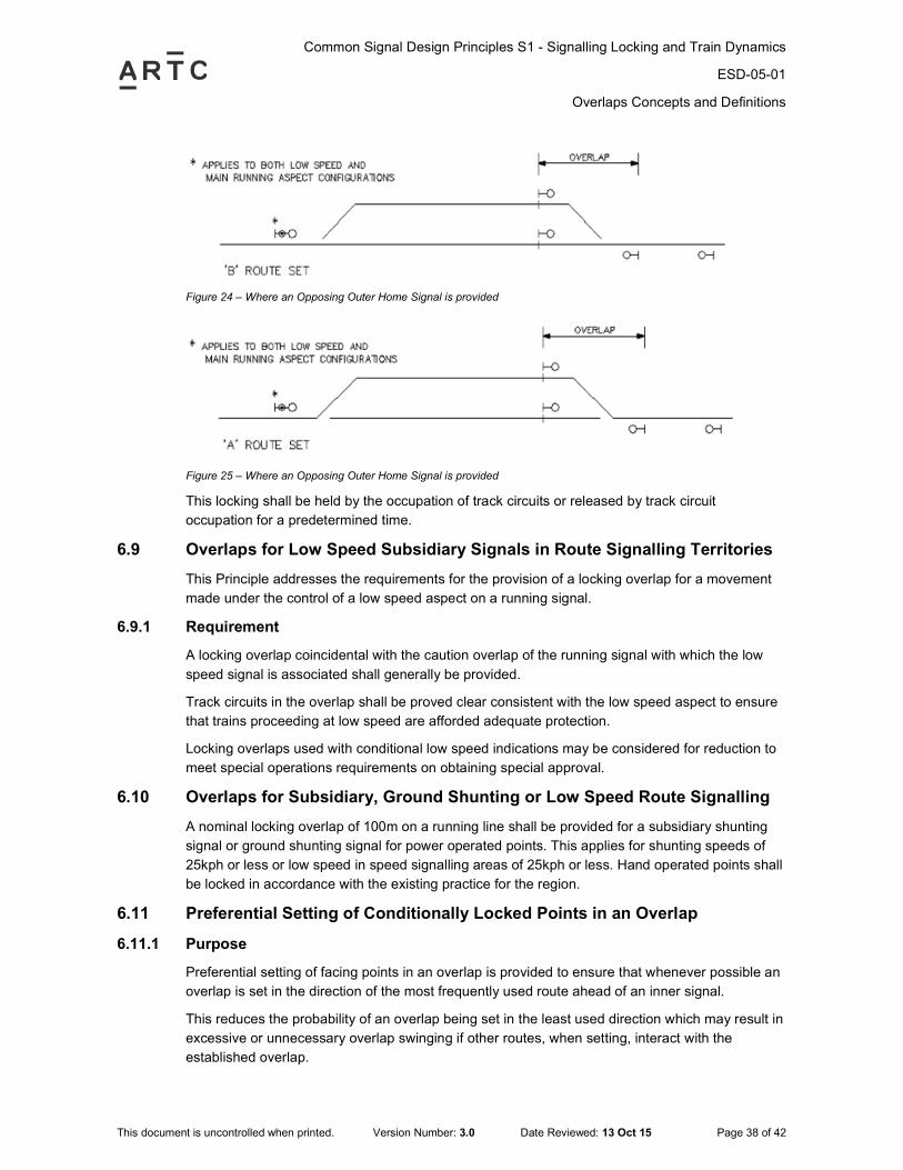
Common Signal Design Principles S1 - Signalling Locking and Train Dynamics
ESD-05-01
Overlaps Concepts and Definitions
This document is uncontrolled when printed. Version Number: 3.0 Date Reviewed: 13 Oct 15 Page 38 of 42
Figure 24 – Where an Opposing Outer Home Signal is provided
Figure 25 – Where an Opposing Outer Home Signal is provided
This locking shall be held by the occupation of track circuits or released by track circuit
occupation for a predetermined time.
6.9 Overlaps for Low Speed Subsidiary Signals in Route Signalling Territories
This Principle addresses the requirements for the provision of a locking overlap for a movement
made under the control of a low speed aspect on a running signal.
6.9.1 Requirement
A locking overlap coincidental with the caution overlap of the running signal with which the low
speed signal is associated shall generally be provided.
Track circuits in the overlap shall be proved clear consistent with the low speed aspect to ensure
that trains proceeding at low speed are afforded adequate protection.
Locking overlaps used with conditional low speed indications may be considered for reduction to
meet special operations requirements on obtaining special approval.
6.10 Overlaps for Subsidiary, Ground Shunting or Low Speed Route Signalling
A nominal locking overlap of 100m on a running line shall be provided for a subsidiary shunting
signal or ground shunting signal for power operated points. This applies for shunting speeds of
25kph or less or low speed in speed signalling areas of 25kph or less. Hand operated points shall
be locked in accordance with the existing practice for the region.
6.11 Preferential Setting of Conditionally Locked Points in an Overlap
6.11.1 Purpose
Preferential setting of facing points in an overlap is provided to ensure that whenever possible an
overlap is set in the direction of the most frequently used route ahead of an inner signal.
This reduces the probability of an overlap being set in the least used direction which may result in
excessive or unnecessary overlap swinging if other routes, when setting, interact with the
established overlap.
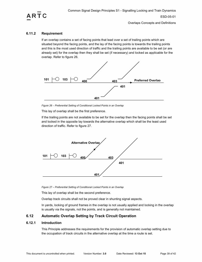
Common Signal Design Principles S1 - Signalling Locking and Train Dynamics
ESD-05-01
Overlaps Concepts and Definitions
This document is uncontrolled when printed. Version Number: 3.0 Date Reviewed: 13 Oct 15 Page 39 of 42
6.11.2 Requirement
If an overlap contains a set of facing points that lead over a set of trailing points which are
situated beyond the facing points, and the lay of the facing points is towards the trailing points
and this is the most used direction of traffic and the trailing points are available to be set (or are
already set) for the overlap then they shall be set (if necessary) and locked as applicable for the
overlap. Refer to figure 26.
Figure 26 – Preferential Setting of Conditional Locked Points in an Overlap
This lay of overlap shall be the first preference.
If the trailing points are not available to be set for the overlap then the facing points shall be set
and locked in the opposite lay towards the alternative overlap which shall be the least used
direction of traffic. Refer to figure 27.
Figure 27 – Preferential Setting of Conditional Locked Points in an Overlap
This lay of overlap shall be the second preference.
Overlap track circuits shall not be proved clear in shunting signal aspects.
In yards, locking of ground frames in the overlap is not usually applied and locking in the overlap
is usually via the signals, not the points, and is generally not maintained.
6.12 Automatic Overlap Setting by Track Circuit Operation
6.12.1 Introduction
This Principle addresses the requirements for the provision of automatic overlap setting due to
the occupation of track circuits in the alternative overlap at the time a route is set.
101 103 400
401
Preferred Overlap 403
401
101 103 400
Alternative Overlap
403
401
401
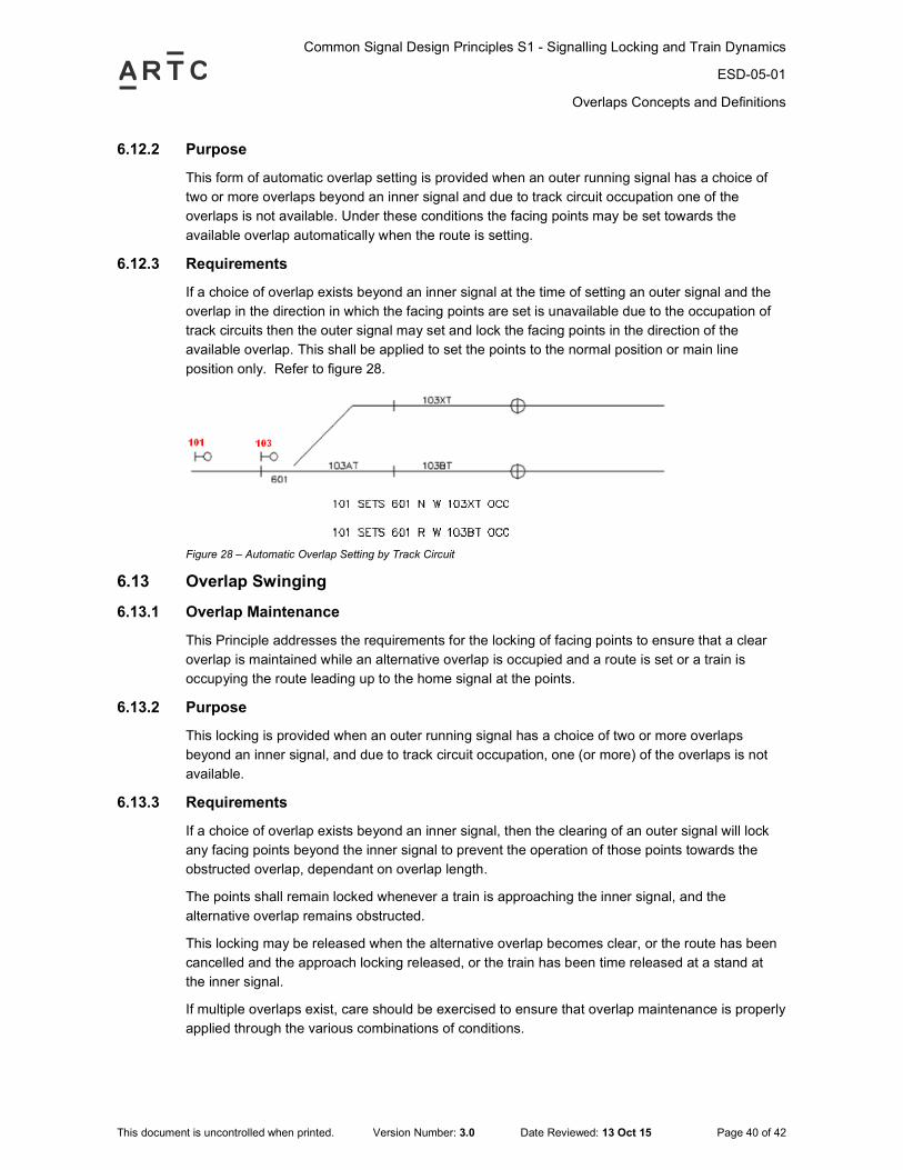
Common Signal Design Principles S1 - Signalling Locking and Train Dynamics
ESD-05-01
Overlaps Concepts and Definitions
This document is uncontrolled when printed. Version Number: 3.0 Date Reviewed: 13 Oct 15 Page 40 of 42
6.12.2 Purpose
This form of automatic overlap setting is provided when an outer running signal has a choice of
two or more overlaps beyond an inner signal and due to track circuit occupation one of the
overlaps is not available. Under these conditions the facing points may be set towards the
available overlap automatically when the route is setting.
6.12.3 Requirements
If a choice of overlap exists beyond an inner signal at the time of setting an outer signal and the
overlap in the direction in which the facing points are set is unavailable due to the occupation of
track circuits then the outer signal may set and lock the facing points in the direction of the
available overlap. This shall be applied to set the points to the normal position or main line
position only. Refer to figure 28.
Figure 28 – Automatic Overlap Setting by Track Circuit
6.13 Overlap Swinging
6.13.1 Overlap Maintenance
This Principle addresses the requirements for the locking of facing points to ensure that a clear
overlap is maintained while an alternative overlap is occupied and a route is set or a train is
occupying the route leading up to the home signal at the points.
6.13.2 Purpose
This locking is provided when an outer running signal has a choice of two or more overlaps
beyond an inner signal, and due to track circuit occupation, one (or more) of the overlaps is not
available.
6.13.3 Requirements
If a choice of overlap exists beyond an inner signal, then the clearing of an outer signal will lock
any facing points beyond the inner signal to prevent the operation of those points towards the
obstructed overlap, dependant on overlap length.
The points shall remain locked whenever a train is approaching the inner signal, and the
alternative overlap remains obstructed.
This locking may be released when the alternative overlap becomes clear, or the route has been
cancelled and the approach locking released, or the train has been time released at a stand at
the inner signal.
If multiple overlaps exist, care should be exercised to ensure that overlap maintenance is properly
applied through the various combinations of conditions.

Common Signal Design Principles S1 - Signalling Locking and Train Dynamics
ESD-05-01
Overlaps Concepts and Definitions
This document is uncontrolled when printed. Version Number: 3.0 Date Reviewed: 13 Oct 15 Page 41 of 42
If only one set of facing points is involved and the alternate path is often used, then automatic
overlap setting should be provided where there is the traffic density to warrant the extra
complexity.
Common Signal Design Principles S1 - Signalling Locking and Train Dynamics
ESD-05-01
Block Sections
This document is uncontrolled when printed. Version Number: 3.0 Date Reviewed: 13 Oct 15 Page 42 of 42
7 Block Sections
Only one train may occupy the block section between two interlockings at any time. Alternatively,
the block may be split into more than one section by intermediate or controlled signals.
In order to set the block section so as to allow entry into the block, the following shall be proved:
a) All opposing signals are normal
b) Releases, which require the block section, are normal. Detection of the release is only
required at time of initiation of the block feed.
c) Entry into the block section from any other section is not available (i.e. all other block relays
false)
d) A block feed which would allow an opposing signal to set, is de-energised
e) No traffic is proceeding from the other end of the block
f) For main signals, all tracks, including all tracks up to the opposing starter signal at next
interlocking clear. Tracks, beyond the overlap and the opposing signal which may be
occupied by a train proceeding in the same direction are not required to be proven clear.
Where a track circuit is included in the block section based on the lie of points (and is not a
fouling track of the points), the points shall be directionally locked based on the condition of
the track circuit.
g) For coded track circuits which have timer constraints for the passage of block occupancy
information, then additional controls are required. The aspect for a starter signal shall prove
the opposing block de-energised before providing a proceed aspect. Where coded track
circuits abut standard track circuits within the section then provision shall be made for
standard track circuit to have a time delay to pick up to compensate for the time delay within
the coded track section. This will ensure that the block occupancy is maintained and
occupied during the passage of a train.