Embed Size (px)
Citation preview

8/2/2019 ES-3511 Service Handbook
http://slidepdf.com/reader/full/es-3511-service-handbook 1/543
MULTIFUNCTIONAL DIGITAL COLOR SYSTEMS
e-STUDIO3511/4511
File No. SHE03000200R03042133500-TTEC
Ver03_2004-10

8/2/2019 ES-3511 Service Handbook
http://slidepdf.com/reader/full/es-3511-service-handbook 2/543
© 2003 TOSHIBA TEC CORPORATION
All rights reserved

8/2/2019 ES-3511 Service Handbook
http://slidepdf.com/reader/full/es-3511-service-handbook 3/543
Be sure not to hold the movable parts or units (e.g. the control panel, ADU or RADF) when
transporting the equipment.
• Be sure to use a dedicated outlet with AC 110/13.2A, 115V or 127V/12A, 220V-240V or 240V/
8A) for its power source.
• The equipment must be grounded for safety.
Never ground it to a gas pipe or a water pipe.
• Select a suitable place for installation.
Avoid excessive heat, high humidity, dust, vibration and direct sunlight.
• Also provide proper ventilation as the equipment emits a slight amount of ozone.
• To insure adequate working space for the copying operation, keep a minimum clearance of
80 cm (32”) on the left, 80 cm (32”) on the right and 10 cm (4”) in the rear.
• The socket-outlet shall be installed near the equipment and shall be easily accessible.
2. Service of Machines
• Basically, be sure to turn the main switch off and unplug the power cord during service.
• Be sure not to touch high-temperature sections such as the exposure lamp, the fuser unit, the
damp heater and their periphery.
• Be sure not to touch high-voltage sections such as the chargers, transfer belt, 2nd transfer roller,
developer, IH control circuit, high-voltage transformer, exposure lamp control inverter, inverter
for the LCD backlight and power supply unit. Especially, the board of these components should
not be touched since the electric charge may remain in the capacitors, etc. on them even after
the power is turned OFF.
• Be sure not to touch rotating/operating sections such as gears, belts, pulleys, fan, etc.
• Be careful when removing the covers since there might be the parts with very sharp edges
underneath.
• When servicing the machines with the main switch turned on, be sure not to touch live sections
and rotating/operating sections. Avoid exposure to laser radiation.
• Use suitable measuring instruments and tools.
• Avoid exposure to laser radiation during servicing.
- Avoid direct exposure to the beam.
- Do not insert tools, parts, etc. that are reflective into the path of the laser beam.
- Remove all watches, rings, bracelets, etc. that are reflective.
• Unplug the power cable and clean the area around the prongs of the plug once a year or more.A fire may occur when dust lies on this area.
GENERAL PRECAUTIONS REGARDING THE INSTALLATIONAND SERVICE FOR e-STUDIO3511/4511
The installation and service should be done by a qualified service technician.
1. Transportation/Installation
• When transporting/installing the equipment, employ four persons and be sure to use the positionsas indicated below.
The equipment is quite heavy and weighs approximately 112kg (246 lb.), therefore pay full attention
when handling it.

8/2/2019 ES-3511 Service Handbook
http://slidepdf.com/reader/full/es-3511-service-handbook 4/543
3. Main Service Parts for Safety
• The breaker, door switch, fuse, thermostat, thermofuse, thermistor, etc. are particularly important
for safety. Be sure to handle/install them properly. If these parts are shor ted circuit and/or made
their functions out, they may burn down, for instance, and may result in fatal accidents. Do not
allow a short circuit to occur. Do not use the parts not recommended by Toshiba TEC Corporation.
4. Cautionary Labels
• During servicing, be sure to check the rating plate and the cautionary labels such as “Unplug the
power cord during service”, “Hot area”, “Laser warning label” etc. to see if there is any dirt on
their surface and whether they are properly stuck to the equipment.
5. Disposition of Consumable Parts, Packing Materials, Used batteries and RAM-ICs
• Regarding the recovery and disposal of the equipment, supplies, consumable parts, packing
materials, used batteries and RAM-ICs including lithium batteries, follow the relevant local
regulations or rules.
6. When parts are disassembled, reassembly is basically the reverse of disassembly unless
otherwise noted in this manual or other related documents. Be careful not to reassemble
small parts such as screws, washers, pins, E-rings, star washers in the wrong places.
7. Basically, the machine should not be operated with any parts removed or disassembled.
8. Precautions Against Static Electricity
• The PC board must be stored in an anti-electrostatic bag and handled carefully using a wristband,
because the ICs on it may become damaged due to static electricity.
Caution: Before using the wristband, pull out the power cord plug of the equipment and
make sure that there are no uninsulated charged objects in the vicinity.
Caution : Dispose of used batteries and RAM-ICs including lithium batteries
according to this manual.
Attention : Se débarrasser de batteries et RAM-ICs usés y compris les batteries
en lithium selon ce manuel.
Vorsicht : Entsorgung des gebrauchten Batterien und RAM-ICs (inklusive
der Lithium-Batterie) nach diesem Handbuch.

8/2/2019 ES-3511 Service Handbook
http://slidepdf.com/reader/full/es-3511-service-handbook 5/543
November 2003 © TOSHIBA TEC i e-STUDIO3511/4511 CONTENTS
CONTENTS
1. SPECIFICATIONS/ACCESSORIES/OPTIONS/SUPPLIES.......................................... 1-1
1.1 Specifications ..................................................................................................................... 1-1
1.2 Accessories........................................................................................................................ 1-5
1.3 Options............................................................................................................................... 1-61.4 Supplies ............................................................................................................................. 1-6
1.5 System List ........................................................................................................................ 1-7
2. ERROR CODE AND SELF-DIAGNOSTIC MODE ........................................................ 2-1
2.1 Error Code List ................................................................................................................... 2-1
2.1.1 Jam ...................................................................................................................... 2-1
2.1.2 Service call .......................................................................................................... 2-6
2.1.3 Error in Internet FAX / Scanning Function.......................................................... 2-11
2.1.4 Printer function error .......................................................................................... 2-19
2.2 Self-diagnosis Modes....................................................................................................... 2-21
2.2.1 Input check (Test mode 03)................................................................................ 2-23
2.2.2 Output check (test mode 03).............................................................................. 2-28
2.2.3 Test print mode (test mode 04) .......................................................................... 2-31
2.2.4 Adjustment mode (05)........................................................................................ 2-32
2.2.5 Setting mode (08) .............................................................................................. 2-76
2.2.6 Pixel counter .................................................................................................... 2-154
2.2.7 Classification List of Adjustment Mode (05) / Setting Mode (08)...................... 2-165
3. ADJUSTMENT .............................................................................................................. 3-1
3.1 Adjustment Order (Image Related Adjustment) ................................................................. 3-1
3.2 Adjustment of the Auto-Toner Sensor ................................................................................ 3-23.3 Performing Image Quality Control ...................................................................................... 3-5
3.4 Image Dimensional Adjustment ......................................................................................... 3-6
3.4.1 General description.............................................................................................. 3-6
3.4.2 Paper alignment at the registration roller ............................................................. 3-8
3.4.3 Printer related adjustment .................................................................................. 3-10
3.4.4 Scanner related adjustment ............................................................................... 3-15
3.5 Image Quality Adjustment (Copying Function) ................................................................. 3-21
3.5.1 Automatic gamma adjustment ........................................................................... 3-21
3.5.2 Density adjustment ............................................................................................ 3-22
3.5.3 Color balance adjustment .................................................................................. 3-243.5.4 Gamma balance adjustment .............................................................................. 3-25
3.5.5 Offsetting adjustment for background processing .............................................. 3-26
3.5.6 Judgment threshold for ACS .............................................................................. 3-27
3.5.7 Sharpness adjustment ....................................................................................... 3-27
3.5.8 Setting range correction ..................................................................................... 3-28
3.5.9 Setting range correction (Adjustment of background peak) ............................... 3-29
3.5.10 Adjustment of smudged/faint text ....................................................................... 3-29
3.5.11 Adaptation to highlighter .................................................................................... 3-30
04/10

8/2/2019 ES-3511 Service Handbook
http://slidepdf.com/reader/full/es-3511-service-handbook 6/543
e-STUDIO3511/4511 CONTENTS ii November 2003 © TOSHIBA TEC
3.5.12 Beam level conversion setting ........................................................................... 3-30
3.5.13 Maximum toner density adjustment to paper type ............................................. 3-31
3.5.14 Maximum text density adjustment...................................................................... 3-31
3.5.15 Text/Photo reproduction level adjustment .......................................................... 3-32
3.5.16 Black reproduction switching at the Twin color copy mode ................................ 3-32
3.6 Image Quality Adjustment (Printing Function) .................................................................. 3-33
3.6.1 Automatic gamma adjustment ........................................................................... 3-33
3.6.2 Gamma balance adjustment (Black Mode) ........................................................ 3-34
3.6.3 Color balance adjustment (Color Mode) ............................................................ 3-35
3.6.4 Adjustment of smudged/faint text ....................................................................... 3-36
3.6.5 Upper limit value at Toner Saving Mode ............................................................ 3-36
3.6.6 Dot size adjustment in black printing ................................................................. 3-37
3.6.7 Maximum toner density adjustment to paper type ............................................. 3-37
3.6.8 Image processing: Gamma correction table all clearing .................................... 3-37
3.7 Image Quality Adjustment (Scanning Function) ............................................................... 3-38
3.7.1 Gamma balance adjustment .............................................................................. 3-38
3.7.2 Density adjustment (Black Mode) ...................................................................... 3-39
3.7.3 Background adjustment (Gray Scale Mode) ...................................................... 3-40
3.7.4 Background adjustment (Color Mode) ............................................................... 3-40
3.7.5 Judgment threshold for ACS .............................................................................. 3-41
3.7.6 Sharpness adjustment ....................................................................................... 3-41
3.7.7 Setting range correction ..................................................................................... 3-42
3.7.8 Setting range correction (Adjustment of background peak) ............................... 3-42
3.7.9 Fine adjustment of black density........................................................................ 3-43
3.7.10 RGB conversion method selection..................................................................... 3-43
3.7.11 Reproduction ratio of primary scanning direction (black) ................................... 3-44
3.7.12 Reproduction ratio of primary scanning direction (color).................................... 3-44
3.8 High-Voltage Transformer Setting .................................................................................... 3-45
3.8.1 General description............................................................................................ 3-45
3.8.2 Setting at the replacement of high-voltage transformer ..................................... 3-45
3.9 Adjustment of the Scanner Section .................................................................................. 3-46
3.9.1 Carriages ........................................................................................................... 3-46
3.9.2 Lens unit ............................................................................................................ 3-50
3.10 Adjustment of the Paper Feeding System ........................................................................ 3-52
3.10.1 Sheet sideways deviation caused by paper feeding .......................................... 3-52
3.11 Adjustment of the Developer Unit .................................................................................... 3-53
3.11.1 Doctor-to-sleeve gap (black developer unit) ...................................................... 3-53
3.11.2 Doctor-to-sleeve gap (color developer unit) ....................................................... 3-54
3.12 Adjustment of the RADF (MR-3015) ................................................................................ 3-56
3.12.1 Adjustment of RADF position ............................................................................. 3-56
3.12.2 Adjustment of RADF height ............................................................................... 3-60
3.12.3 Adjustment of skew............................................................................................ 3-61
3.12.4 Automatic adjustment of sensors and initialization of EEPROM........................ 3-62
3.12.5 Adjustment of aligning........................................................................................ 3-63
3.12.6 Adjustment of aligning at reversing .................................................................... 3-64
04/10
8/2/2019 ES-3511 Service Handbook
http://slidepdf.com/reader/full/es-3511-service-handbook 7/543
November 2003 © TOSHIBA TEC iii e-STUDIO3511/4511 CONTENTS
3.12.7 Adjustment of reverse solenoid .......................................................................... 3-65
3.12.8 Adjustment of RADF opening/closing switch ..................................................... 3-67
3.12.9 Adjustment of RADF opening/closing sensor .................................................... 3-68
3.12.10 Adjustment of tray volume ................................................................................. 3-69
3.13 Adjustment of the Finisher (MJ-1022) .............................................................................. 3-70
3.13.1 Adjusting the jogging plate width ....................................................................... 3-70
3.13.2 Adjusting the angle of the jogging plate ............................................................. 3-72
3.13.3 Adjusting the overlap of the sensor flag ............................................................. 3-73
3.13.4 Adjusting the tension of the stack processing motor belt ................................... 3-74
3.13.5 Releasing the stack tray guide lever fixing plate ................................................ 3-76
3.13.6 Adjustment of the upper tray angle .................................................................... 3-77
3.13.7 DIP switch functions ........................................................................................... 3-79
3.14 Adjustment of the Finisher (MJ-1023/1024) ..................................................................... 3-81
3.14.1 Adjusting the alignment position (Finisher unit) ................................................. 3-81
3.14.2 Adjusting the staple position (Finisher unit) ....................................................... 3-82
3.14.3 Adjusting the folding position (Saddle stitcher unit) ........................................... 3-84
3.14.4 Fine adjustment of binding/folding position (Saddle stitcher unit) ...................... 3-87
3.14.5 Sensor output adjustment (Puncher unit) .......................................................... 3-87
3.14.6 Registering the number of punch holes (Puncher unit) ...................................... 3-88
3.15 Key Copy Counter (MU-8, MU-10) ................................................................................... 3-89
4. PREVENTIVE MAINTENANCE (PM)............................................................................4-1
4.1 PM Support Mode .............................................................................................................. 4-1
4.1.1 General description.............................................................................................. 4-1
4.1.2 Operational flow and operational screen ............................................................. 4-1
4.1.3 Work flow of parts replacement ........................................................................... 4-6
4.2 General Descriptions for PM Procedure ............................................................................ 4-74.3 Operational Items in Overhauling....................................................................................... 4-7
4.4 Preventive Maintenance Checklist ..................................................................................... 4-8
4.5 PM KIT ............................................................................................................................. 4-23
4.6 Jig List .............................................................................................................................. 4-24
4.7 Grease List....................................................................................................................... 4-24
4.8 Precautions for Storing and Handling Supplies................................................................ 4-25
4.8.1 Precautions for storing TOSHIBA supplies ........................................................ 4-25
4.8.2 Checking and cleaning of photoconductive drum .............................................. 4-26
4.8.3 Checking and cleaning of drum cleaning blade and transfer belt cleaning
blade .................................................................................................................. 4-27
4.8.4 Handling of drum cleaner brush ......................................................................... 4-27
4.8.5 Handling of transfer belt ..................................................................................... 4-27
4.8.6 Checking and cleaning of fuser belt and pressure roller .................................... 4-27
4.8.7 Checking and replacing the oil roller and cleaning roller.................................... 4-28
5. TROUBLESHOOTING .................................................................................................. 5-1
5. Diagnosis and Prescription for Each Error Code ............................................................... 5-1
5.1.1 Paper transport jam (paper exit section) .............................................................. 5-1
5.1.2 Paper misfeeding ................................................................................................. 5-2
5.1.3 Paper transport jam ............................................................................................. 5-8
04/09

8/2/2019 ES-3511 Service Handbook
http://slidepdf.com/reader/full/es-3511-service-handbook 8/543
e-STUDIO3511/4511 CONTENTS iv November 2003 © TOSHIBA TEC
04/10
5.1.4 Other paper jam ................................................................................................. 5-16
5.1.5 Cover open jam ................................................................................................. 5-19
5.1.6 RADF jam .......................................................................................................... 5-23
5.1.7 Finisher jam ....................................................................................................... 5-28
5.1.8 Drive system related service call ....................................................................... 5-41
5.1.9 Paper feeding system related service call ......................................................... 5-42
5.1.10 Scanning system related service call ................................................................. 5-46
5.1.11 Fuser unit related service call ............................................................................ 5-47
5.1.12 Communication related service call ................................................................... 5-50
5.1.13 RADF related service call .................................................................................. 5-51
5.1.14 Circuit related service call .................................................................................. 5-52
5.1.15 Laser optical unit related service call ................................................................. 5-55
5.1.16 Finisher related service call ............................................................................... 5-56
5.1.17 Image control related service call ...................................................................... 5-70
5.1.18 Copy process related service call ...................................................................... 5-74
5.1.19 Toner density control related service call ........................................................... 5-78
5.1.20 Other service call ............................................................................................... 5-82
5.1.21 Error in Internet FAX / Scanning Function.......................................................... 5-83
5.2 Troubleshooting of Image .............................................................................................. 5-100
5.3 Replacement of PC Boards and HDD ............................................................................ 5-137
5.3.1 Replacing HDD ................................................................................................ 5-137
5.3.2 Replacing SYS board....................................................................................... 5-139
5.3.3 Replacing SLG board ...................................................................................... 5-141
5.3.4 NVRAM replacing and clearing ........................................................................ 5-141
6. FIRMWARE UPDATING................................................................................................ 6-1
6.1 Firmware Updating with Download Jig ............................................................................... 6-26.1.1 PWA-DWNLD-350-JIG2 (48 MB) ......................................................................... 6-4
6.1.2 PWA-DWNLD-350-JIG1 (16 MB) ....................................................................... 6-10
6.1.3 Writing the data to the download jig (PWA-DWNLD-350-JIG) ........................... 6-20
6.1.4 K-PWA-DLM-320 ............................................................................................... 6-21
6.2 Firmware Updating with FSMS (Field Service Manager) ................................................. 6-35
6.3 Firmware Updating with USB Storage Device .................................................................. 6-47
<Appendix> Assist Mode ......................................................................................................... 6-61
7. POWER SUPPLY UNIT ................................................................................................. 7-1
7.1 Output Channel .................................................................................................................. 7-1
7.2 Fuse ................................................................................................................................... 7-3
7.3 Configuration of Power Supply Unit ................................................................................... 7-4
8. REMOTE SERVICE....................................................................................................... 8-1
8.1 Auto Supply Order.............................................................................................................. 8-1
8.1.1 Outline ................................................................................................................. 8-1
8.1.2 Setting Item.......................................................................................................... 8-2
8.1.3 Setting procedure ................................................................................................ 8-4
8.1.4 Order Sheet Format ........................................................................................... 8-12

8/2/2019 ES-3511 Service Handbook
http://slidepdf.com/reader/full/es-3511-service-handbook 9/543
November 2003 © TOSHIBA TEC v e-STUDIO3511/4511 CONTENTS
8.2 Service Notification .......................................................................................................... 8-14
8.2.1 Outline ............................................................................................................... 8-14
8.2.2 Setting................................................................................................................ 8-14
8.2.2.1 Preparation ............................................................................................ 8-14
8.2.2.2 Setting procedure ................................................................................... 8-15
8.2.3 Items to be notified ............................................................................................. 8-19
9. WIRE HARNESS CONNECTION DIAGRAMS ............................................................. 9-1
9.1 AC Wire Harness ............................................................................................................... 9-1
9.2 DC Wire Harness ..................................................................................................... Appendix
9.3 Connector Table ....................................................................................................... Appendix

8/2/2019 ES-3511 Service Handbook
http://slidepdf.com/reader/full/es-3511-service-handbook 10/543
e-STUDIO3511/4511 CONTENTS vi November 2003 © TOSHIBA TEC

8/2/2019 ES-3511 Service Handbook
http://slidepdf.com/reader/full/es-3511-service-handbook 11/543
1. SPECIFICATIONS/ ACCESSORIES/OPTIONS/ SUPPLIES
2. ERROR CODE ANDSELF-DIAGNOSTIC MODE
3. ADJUSTMENT
4. PREVENTIVE MAINTENANCE(PM)
5. TROUBLESHOOTING
6. FIRMWARE UPDATING
7. POWER SUPPLY UNIT
8. REMOTE SERVICE
9. WIRE HARNESSCONNECTION DIAGRAMS

8/2/2019 ES-3511 Service Handbook
http://slidepdf.com/reader/full/es-3511-service-handbook 12/543

8/2/2019 ES-3511 Service Handbook
http://slidepdf.com/reader/full/es-3511-service-handbook 13/543
November 2003 © TOSHIBA TEC 1 - 1 e-STUDIO3511/4511 SPECIFICATIONS
1. SPECIFICATIONS/ACCESSORIES/OPTIONS/SUPPLIES
1.1 Specifications
Values in [ ] are for e-STUDIO4511 in case that the specification is different between e-STUDIO3511
and e-STUDIO4511.
Copy process Indirect electrophotographic process (dry)
• Type Desktop type (Console type: when optional Paper Feed Pedestal (PFP) or
optional Large Capacity Feeder (LCF) is installed.)
• Original table Fixed type (the left rear corner used as guide to place originals)
• Accepted originals Sheet, book and 3-dimentional object
For single-sided originals – 50-127 g/m2 (13-34 lb. Bond)
For double-sided originals – 50-105 g/m2 (13-28 lb. Bond)
None of the carbon, bonded nor stapled sheet original is acceptable when
using the optional Reversing Automatic Document Feeder.
Maximum size: A3/LD• Copy speed (Copies/min.)
e-STUDIO3511
* “–” means “Not acceptable”.
* The copy speed in the above table are available when originals are manually placed for single side,continuous copying.
* When the Reversing Automatic Document Feeder is used, the copy speed of 35[45] sheets per
minute is only available under the following conditions:
• Original/Mode: Single-sided original/A4/LT size. APS/automatic density are not selected. /Plain
paper.
• Number of sheets: 35[45] or more at the black mode and 11 or more at the color mode.
• Reproduction ratio: 100%
* The values in ( ) are available when printed at color mode.
e-STUDIO4511
Paper supply
Paper size
A4, LT, B5
A4-R, B5-R,
A5-R, LT-R, ST-R
B4, LG
A3, LD
Drawer
35 (11)
28 ( 5 )
24 ( 5 )
21 ( 5 )
Bypass feed
(Size specified)
35 (11)
28 ( 5 )
24 ( 5 )
21 ( 5 )
PFP
35 (11)
28 ( 5 )
24 ( 5 )
21 ( 5 )
LCF
35 (11)
–
–
–
Paper supply
Paper size
A4, LT, B5
A4-R, B5-R,
A5-R, LT-R, ST-R
B4, LG
A3, LD
Drawer
45 (11)
32 ( 5 )
26 ( 5 )
22 ( 5 )
Bypass feed
(Size specified)
45 (11)
32 ( 5 )
26 ( 5 )
22 ( 5 )
PFP
45 (11)
32 ( 5 )
26 ( 5 )
22 ( 5 )
LCF
45 (11)
–
–
–

8/2/2019 ES-3511 Service Handbook
http://slidepdf.com/reader/full/es-3511-service-handbook 14/543
e-STUDIO3511/4511 SPECIFICATIONS 1 - 2 November 2003 © TOSHIBA TEC
- The system copy speed is available when 10 sheets of A4/LT size original are set on the RADF
and one of the copy modes in the above table is selected.- The period of time from pressing [START] to displaying "READY" is the actually measured
value.
- Setting: Automatic exposure OFF, APS/AMS OFF, Text/Photo Mode, feeding from the upper
drawer and Sort Mode.
- The finisher with the saddle stitcher and hole punch unit are not installed.
- The values in ( ) are the speeds at the color modes.
• Copy paper
PFPSize
Weight
Specialpaper
64 to 105 g/m2
17 to 28 lb. Bond
-
Bypass copyA3 to A6-R, LD to ST-R,
13" LG, 8.5" SQ,
305 x 457 mm (12" x 18")
(Non-standard or user-
specified sizes can be set.)
64 to 209 g/m2,17 lb. Bond
to 110 lb. Index
(Continuous feeding)
64 to 209 g/m2, 17 lb. Bond
to 110 lb. Index
(Single paper feeding)
Labels, OHP film(thickness: 80 µm or thicker)
A3 to A5-R
LD to ST-R, 13" LG,
8.5" SQ
Remarks
Special paper recommended byToshiba Tec
* System copy speed
• First copy time ................... Approx. 6.8 sec. or less (black), approx. 16.2 sec. or less (color)
(A4/LT, upper drawer, 100%, original placed manually)
• Warming-up time ............... Approx. 40 seconds (Stand-alone, temperature: 20°C)
• Multiple copying ................ Up to 999 copies; Key in set numbers
Copy mode
Single-sided originals
↓
Single-sided copies
Single-sided originals
↓
Double-sided copies
Double-sided originals
↓
Double-sided copies
Double-sided originals
↓
Single-sided copies
1 set
3 sets
5 sets
1 set
3 sets
5 sets
1 set
3 sets
5 sets
1 set
3 sets
5 sets
Sec.
e-STUDIO3511 e-STUDIO4511
22.9 (70.3)
60.9 (181.8)
94.8 (292.2)
31.3 (95.1)
70.7 (201.8)
110.1 (311.2)
59.6 (149.6)
138.7 (366.6)
217.3 (584.6)
51.2 (124.6)
120.8 (346.5)
188.7 (565.7)
19.8 (70.3)
49.9 (181.8)
76.3 (292.2)
30.3 (95.1)
71.9 (201.8)
101.5 (311.2)
59.5 (149.6)
130.4 (366.6)
201.5 (584.6)
51.5 (124.6)
105.7 (346.5)
158.5 (565.7)
Drawer ADU LCF
A4,
LT
04/10

8/2/2019 ES-3511 Service Handbook
http://slidepdf.com/reader/full/es-3511-service-handbook 15/543
November 2003 © TOSHIBA TEC 1 - 3 e-STUDIO3511/4511 SPECIFICATIONS
• Reproduction ratio .............Actual ratio: 100±0.5%
Zooming: 25 - 400% in increments of 1%
(25 - 200% when using RADF)
• Resolution/Gradation ........ Read: 600 dpi
Write: Equivalent to 2400 dpi x 600 dpi (black copy)
Equivalent to 600 dpi x 600 dpi (color copy)
• Eliminated portion .............Leading edge : 3.0±2.0 mm, Side/trailing edges: 2.0±2.0 mm (black copy)
Leading edge : 5.0±2.0 mm, Side/trailing edges: 2.0±2.0 mm (color copy)
Leading/trailing edges: 5.0±2.0 mm, Side edges: 5.0±2.0 mm (black/color
print)
• Paper feeding.................... Drawers in the equipment – 2 drawers (stack height 60.5 mm, equivalent
to 550 sheets; 64-80 g/m2 (17-22 lb. Bond))
PFP – Option (1 or 2 drawers: stack height 60.5 mm, equivalent to 550
sheets; 64-80 g/m2 (17-22 lb. Bond))
LCF – Option (stack height 137.5 mm x 2, equivalent to 2500 sheets; 64-80
g/m2 (17-22 lb. Bond))
Bypass feed – Stack height 11 mm, equivalent to 100 sheets; 64-80 g/m 2
(17-22 lb. Bond)
• Capacity of originals in the Reversing Automatic Document Feeder (Option)
................. A3 to A5-R, LD to ST-R: 100 sheets/80 g/m2 (Stack height 16mm or less)
• Automatic duplexing unit ...Stackless/switchback type
• Toner supply ...................... Automatic toner density detection/supply
Toner cartridge replacing method
• Density control .................. Automatic density mode and manual density mode selectable in 11 steps
• Weight ............................... Approx. 112 kg (246.9 lb.)
• Power requirements .......... AC 110V/13.2A, AC 115V or 127V/15A, 220–240V or 240V/8A (50/60 Hz)
* The acceptable value of each voltage is ±10%.
• Power consumption .......... 1.5 kW or less (100V series), 1.7 kW or less (200V series)
* The electric power is supplied to the reversing automatic document feeder, finisher, PFP and LCF
through the equipment.
• Total counter .....................Electronic counter

8/2/2019 ES-3511 Service Handbook
http://slidepdf.com/reader/full/es-3511-service-handbook 16/543
e-STUDIO3511/4511 SPECIFICATIONS 1 - 4 November 2003 © TOSHIBA TEC
• Dimensions of the equipment .......... See the figure below (W660 x D718 x H739 mm)
6 6 0
7 1 8
45°
7 3 9
Fig. 1-101
* When the tilt angle of the control panel is 45 degrees.

8/2/2019 ES-3511 Service Handbook
http://slidepdf.com/reader/full/es-3511-service-handbook 17/543
November 2003 © TOSHIBA TEC 1 - 5 e-STUDIO3511/4511 SPECIFICATIONS
Unpacking/Setup instruction 1 set
Operator’s manual 4 pcs. (except for MJD)
Operator's manual pocket 1 pc.
Power cable 1 pc.Warranty sheet 1 pc. (for NAD)
Setup report 1 set (for NAD and MJD)
Customer satisfaction card 1 pc. (for MJD)
PM sticker 1 pc. (for MJD)
Drum (installed inside of the equipment) 1 pc.
Control panel stopper 1 pc.
Lever 1 pc.
Color developer holder 6 pcs.
Rubber plug 4 pcs.Blind seal (small / large) 3 pcs. / 1pc.
CD-ROM 4 pcs.
Developer material (Y, M, C, K) 1 pc. each (for TWD)
Screw M3 x 8 / M4 x 8 1 pc. / 1pc.
1.2 Accessories
* Machine version
NAD: North America
MJD: Europe
AUD: Australia
ASD: Asia
TWD: Taiwan
SAD: Saudi Arabia
JPD: Japan

8/2/2019 ES-3511 Service Handbook
http://slidepdf.com/reader/full/es-3511-service-handbook 18/543
e-STUDIO3511/4511 SPECIFICATIONS 1 - 6 November 2003 © TOSHIBA TEC
1.3 Options
Notes:
1. The bridge kit (KN-3511) is necessary for installation of the finisher (MJ-1022, MJ-1023 or
MJ-1024).
2. The finisher (MJ-1023 or MJ-1024) is necessary for installation of the hole punch unit
(MJ-6004N/E/F/S).
3. The PCI slot (GO-1030) is necessary for installation of the scrambler board (GP-1030).
1.4 Supplies
Platen cover KA-3511PC
Reversing Automatic Document Feeder (RADF) MR-3015
Drawer module MY-1021
Paper Feed Pedestal (PFP) KD-1011
Large Capacity Feeder (LCF) KD-1012 A4/LT
Finisher (Hanging type) MJ-1022
Finisher (Console type) MJ-1023, MJ-1024 (with saddle stitcher)
Hole punch unit MJ-6004 N/E/F/S
Staple cartridge STAPLE-1600 (for hanging type)
STAPLE-2000 (for console type)
STAPLE-600 (for saddle stitcher)
Bridge kit KN-3511
Key copy counter, key copy counter socket MU-8, MU-10
Work table KK-3511Damp heater kit MF-3511
FAX board GD-1150
FAX board 2nd line GD-1160
Expansion memory GC-1180
Wireless LAN adapter GN-1010
PCI slot GO-1030
Scrambler board GP-1030
Drum PS-OD3511Toner bag PS-TB3511
Toner cartridge (K) PS-ZT3511 *K, PS-ZT3511K
Toner cartridge (Y) PS-ZT3511 *Y, PS-ZT3511Y
Toner cartridge (M) PS-ZT3511 *M, PS-ZT3511M
Toner cartridge (C) PS-ZT3511 *C, PS-ZT3511C
Marked * : E, D, C and T

8/2/2019 ES-3511 Service Handbook
http://slidepdf.com/reader/full/es-3511-service-handbook 19/543
November 2003 © TOSHIBA TEC 1 - 7 e-STUDIO3511/4511 SPECIFICATIONS
1.5 System List
Fig. 1-501
R e v e r s i n g A u t o m a t i c
D o c u m e n t F e e d e r
( R A D F )
M R - 3 0 1 5
P l a t e n c o v e r
K A - 3 5 1 1 P C
W o r k t a b l e
K K - 3 5 1 1
K
e y c o p y c o u n t e r
M U 8 , M U - 1 0
D a m p h e a t e r
M F - 3 5 1 1
L a r g e C a p a c i t y F e e d e r
( L C F )
K D - 1 0 1 2 A
4 / L T
P a p e r F e e d P e d e s t a l
( P F P )
K D - 1 0 1 1
D r a w e r m o d u l e
M Y - 1 0 2 1
S t a p l e c a r t r i d g e
S T A P L E - 6 0 0
F i n i s h e r
M J - 1 0 2 2
F i n i s h e r
M J - 1 0 2 3
F i n i s h e r
M J - 1 0 2 4
S t a p l e c a r t r i d g e
S T A P L E - 2 0 0 0
S t a p l e c a r t r i d g e
S T A P L E - 1 6 0 0
H o l e p u n c h u n i t
M J - 6 0 0 4 N / E / F / S
B r i d g e k i t
K N - 3 5 1 1
F A X b o a r d
G D - 1 1 5 0
F A X b o a r d 2 n d l i n e
G D - 1 1 6 0
E x p a n s i o n m e m o r y
G C - 1 1 8 0
W i r e l e s s L A N a d a p t e r
G N - 1 0 1 0
P C I s l o t
G O - 1 0 3 0
S c r a m b l e r b o a r d
G P - 1 0 3 0

8/2/2019 ES-3511 Service Handbook
http://slidepdf.com/reader/full/es-3511-service-handbook 20/543
e-STUDIO3511/4511 SPECIFICATIONS 1 - 8 November 2003 © TOSHIBA TEC
8/2/2019 ES-3511 Service Handbook
http://slidepdf.com/reader/full/es-3511-service-handbook 21/543
November 2003 © TOSHIBA TEC 2 - 1 e-STUDIO3511/4511 ERROR CODE AND SELF-DIAGNOSTIC MODE
2. ERROR CODE AND SELF-DIAGNOSTIC MODE
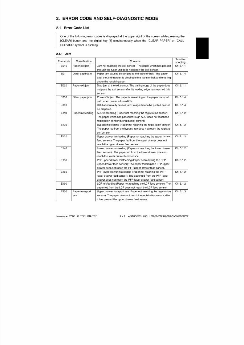
2.1 Error Code List
One of the following error codes is displayed at the upper right of the screen while pressing the
[CLEAR] button and the digital key [8] simultaneously when the “CLEAR PAPER” or “CALL
SERVICE” symbol is blinking.
2.1.1 Jam
E010
E011
E020
E030
E090
E110
E120
E130
E140
E150
E160
E190
E200
Paper exit jam
Other paper jam
Paper exit jam
Other paper jam
Paper misfeeding
Paper transport
jam
Trouble-shootingError code Classification Contents
Jam not reaching the exit sensor : The paper which has passed
through the fuser unit does not reach the exit sensor.
Paper jam caused by clinging to the transfer belt: The paper
after the 2nd transfer is clinging to the transfer belt and entering
under the receiving tray.
Stop jam at the exit sensor: The trailing edge of the paper doesnot pass the exit sensor after its leading edge has reached this
sensor.
Power-ON jam: The paper is remaining on the paper transport
path when power is turned ON.
HDD abnormality causes jam: Image data to be printed cannot
be prepared.
ADU misfeeding (Paper not reaching the registration sensor):
The paper which has passed through ADU does not reach the
registration sensor during duplex printing.
Bypass misfeeding (Paper not reaching the registration sensor):
The paper fed from the bypass tray does not reach the registra-tion sensor.
Upper drawer misfeeding (Paper not reaching the upper drawer
feed sensor): The paper fed from the upper drawer does not
reach the upper drawer feed sensor.
Lower drawer misfeeding (Paper not reaching the lower drawer
feed sensor): The paper fed from the lower drawer does not
reach the lower drawer feed sensor.
PFP upper drawer misfeeding (Paper not reaching the PFP
upper drawer feed sensor): The paper fed from the PFP upper
drawer does not reach the PFP upper drawer feed sensor.
PFP lower drawer misfeeding (Paper not reaching the PFPlower drawer feed sensor): The paper fed from the PFP lower
drawer does not reach the PFP lower drawer feed sensor.
LCF misfeeding (Paper not reaching the LCF feed sensor): The
paper fed from the LCF does not reach the LCF feed sensor.
Upper drawer transport jam (Paper not reaching the registration
sensor): The paper does not reach the registration sensor after
it has passed the upper drawer feed sensor.
Ch. 5.1.1
Ch. 5.1.4
Ch. 5.1.1
Ch. 5.1.4
Ch. 5.1.4
Ch. 5.1.2
Ch. 5.1.2
Ch. 5.1.2
Ch. 5.1.2
Ch. 5.1.2
Ch. 5.1.2
Ch. 5.1.2
Ch. 5.1.3

8/2/2019 ES-3511 Service Handbook
http://slidepdf.com/reader/full/es-3511-service-handbook 22/543
e-STUDIO3511/4511 ERROR CODE AND SELF-DIAGNOSTIC MODE 2 - 2 November 2003 © TOSHIBA TEC
E210
E220
E300
E310
E320
E330
E340
E350
E360
E3C0
E3D0
E3E0
E400
E410
Paper transport
jam
Cover open jam
Lower drawer transport jam (Paper not reaching the registration
sensor): The paper does not reach the registration sensor after
it has passed the upper drawer feed sensor.
Lower drawer transport jam (Paper not reaching the upper
drawer feed sensor): The paper does not reach the upper
drawer feed sensor after it has passed the lower drawer feed
sensor.
PFP upper drawer transport jam (Paper not reaching the
registration sensor): The paper does not reach the registration
sensor after it has passed the upper drawer feed sensor.
PFP upper drawer transport jam (Paper not reaching the upper
drawer feed sensor): The paper does not reach the upper
drawer feed sensor after it has passed the lower drawer feed
sensor.
PFP upper drawer transport jam (Paper not reaching the lower
drawer feed sensor): The paper does not reach the lower
drawer feed sensor after it has passed the PFP upper drawer
feed sensor.
PFP lower drawer transport jam (Paper not reaching the
registration sensor): The paper does not reach the registration
sensor after it has passed the upper drawer feed sensor.
PFP lower drawer transport jam (Paper not reaching the upper
drawer feed sensor): The paper does not reach the upper
drawer feed sensor after it has passed the lower drawer feed
sensor.
PFP lower drawer transport jam (Paper not reaching the lower
drawer feed sensor): The paper does not reach the lower
drawer feed sensor after it has passed the PFP upper drawer
feed sensor.
PFP lower drawer transport jam (Paper not reaching the PFP
upper drawer feed sensor): The paper does not reach the PFP
upper drawer feed sensor after it has passed the PFP lower
drawer feed sensor.
LCF transport jam (Paper not reaching the registration sensor):
The paper does not reach the registration sensor after it has
passed the upper drawer feed sensor.
LCF transport jam (Paper not reaching the upper drawer feed
sensor): The paper does not reach the upper drawer feed
sensor after it has passed the lower drawer feed sensor.
LCF transport jam (Paper not reaching the lower drawer feed
sensor): The paper does not reach the lower drawer feed
sensor after it has passed the LCF feed sensor.
Jam access cover open jam: The jam access cover has opened
during printing.
Front cover open jam: The front cover has opened during
printing.
Ch. 5.1.3
Ch. 5.1.3
Ch. 5.1.3
Ch. 5.1.3
Ch. 5.1.3
Ch. 5.1.3
Ch. 5.1.3
Ch. 5.1.3
Ch. 5.1.3
Ch. 5.1.3
Ch. 5.1.3
Ch. 5.1.3
Ch. 5.1.5
Ch. 5.1.5
Trouble-shootingError code Classification Contents

8/2/2019 ES-3511 Service Handbook
http://slidepdf.com/reader/full/es-3511-service-handbook 23/543
November 2003 © TOSHIBA TEC 2 - 3 e-STUDIO3511/4511 ERROR CODE AND SELF-DIAGNOSTIC MODE
E420
E430
E440
E450
E480
E510
E520
E550
E711
E712
E713
E714
E721
E722
E723
E724
E725
E726
Cover open jam
Paper transport
jam (ADU section)
Other paper jam
RADF jam
PFP side cover open jam: The PFP side cover has opened
during printing.
ADU open jam: The ADU has opened during printing.
Side cover open jam: The side cover has opened during
printing.
LCF side cover open jam: The LCF side cover has opened
during printing.
Bridge unit open jam: The bridge unit has opened during
printing.
Stop jam in the ADU: The paper does not reach the ADU exit
sensor after it has passed the ADU entrance sensor.
Jam not reaching the ADU entrance sensor: The paper does
not reach the ADU entrance sensor after it is switchbacked in
the exit section.
Paper remaining jam on the transport path: The paper is
remaining on the transport path when printing is finished
(caused by a multiple paper feeding).
Jam not reaching the original length sensor: The original fed
from the original feeding tray does not reach the original length
sensor.
Jam not reaching the registration sensor: The original fed from
the original feeding tray does not reach the registration sensor.
Stop jam at the original length sensor: The trailing edge of the
original does not pass the original length sensor after its leading
edge has reached this sensor.
Feed signal reception jam: The feed signal is received even no
original exists on the original feeding tray.
Jam not reaching the read sensor: The original does not reach
the read sensor after it has passed the registration sensor
(when scanning obverse side) or the reverse sensor (when
scanning reverse side).
Jam not reaching the exit sensor (during scanning): The original
which passed the read sensor does not reach the exit sensor
when it is transported from the scanning section to exit section.
Jam not reaching the reverse sensor (during scanning): The
original which passed the read sensor does not reach the
reverse sensor when it is transported from the scanning section
to reverse section.
Stop jam at the registration sensor: The trailing edge of the
original does not pass the registration sensor after its leading
edge has reached this sensor.
Stop jam at the read sensor: The trailing edge of the original
does not pass the read sensor after its leading edge has
reached this sensor.
Transport/exit signal reception jam: RADF receives the transport/
exit reception signal from the equipment when no original is at the
exposure waiting position.
Ch. 5.1.5
Ch. 5.1.5
Ch. 5.1.5
Ch. 5.1.5
Ch. 5.1.5
Ch. 5.1.3
Ch. 5.1.3
Ch. 5.1.4
Ch. 5.1.6
Ch. 5.1.6
Ch. 5.1.6
Ch. 5.1.6
Ch. 5.1.6
Ch. 5.1.6
Ch. 5.1.6
Ch. 5.1.6
Ch. 5.1.6
Ch. 5.1.6
Trouble-shootingError code Classification Contents

8/2/2019 ES-3511 Service Handbook
http://slidepdf.com/reader/full/es-3511-service-handbook 24/543
e-STUDIO3511/4511 ERROR CODE AND SELF-DIAGNOSTIC MODE 2 - 4 November 2003 © TOSHIBA TEC
Stop jam at the exit sensor: The trailing edge of the original
does not pass the exit sensor after its leading edge has
reached this sensor.
Stop jam at the reverse sensor: The trailing edge of the original
does not pass the reverse sensor after its leading edge has
reached this sensor.
Jam not reaching the reverse sensor (during reverse feeding):
The leading edge of the original does not reach the reverse
sensor when original is fed from the reverse section.
Jam not reaching the exit sensor (during reverse feeding): The
original does not reach the exit sensor after it has passed the
reverse sensor when the original is exited from the reverse
section.
Jam access cover open: The jam access cover has opened
during RADF operation.
RADF open jam: RADF has opened during RADF operation.
Jam at the bridge unit transport sensor 1: The paper does not
reach the bridge unit transport sensor 1 after it has passed the
exit sensor.
Stop jam at the bridge unit transport sensor 1: The trailing edge
of the paper does not pass the bridge unit transport sensor 1
after its leading edge has reached the sensor.
Jam at the bridge unit transport sensor 2: The trailing edge of
the paper does not reach the bridge unit transport sensor 2
after its leading edge has reached the bridge unit transport
sensor 1.
Stop jam at the bridge unit transport sensor 2: The trailing edge
of the paper does not pass the bridge unit transport sensor 2
after its leading edge has reached the bridge unit transport
sensor 2.
Punching jam: Punching is not performed properly.
[MJ-1023/1024 (when MJ-6004 is installed)]
Paper transport delay jam: The paper which has passed the bridge
unit does not reach the inlet sensor. [MJ-1022/1023/1024]
Paper transport stop jam:
(1) The paper does not pass through the inlet sensor.
[MJ-1022/1023/1024]
(2) The paper has passed through the inlet sensor but does not
reach or pass the feed path sensor or processing tray sensor.
[MJ-1023/1024]
Power-ON jam:
(1) Paper exists at the inlet sensor when power is turned ON.
[MJ-1022/1023/1024]
(2) Paper exists at the feed path sensor or processing tray
sensor when power is turned ON. [MJ-1023/1024]
Trouble-shootingError code Classification Contents
Ch. 5.1.6
Ch. 5.1.6
Ch. 5.1.6
Ch. 5.1.6
Ch. 5.1.6
Ch. 5.1.6
Ch. 5.1.7 (1)
Ch. 5.1.7 (1)
Ch. 5.1.7 (1)
Ch. 5.1.7 (1)
Ch. 5.1.7 (4)
Ch. 5.1.7 (2)
Ch. 5.1.7 (2)
Ch. 5.1.7 (2)
RADF jam
Finisher jam
(Bridge unit)
Finisher jam
(Punch unit)
Finisher jam
(Finisher section)
E731
E741
E742
E743
E860
E870
E910
E920
E930
E940
E9F0
EA10
EA20
EA30

8/2/2019 ES-3511 Service Handbook
http://slidepdf.com/reader/full/es-3511-service-handbook 25/543
November 2003 © TOSHIBA TEC 2 - 5 e-STUDIO3511/4511 ERROR CODE AND SELF-DIAGNOSTIC MODE
Door open jam:
(1) The finisher has been released from the equipment during
printing. [MJ-1022]
(2) The upper/front cover of the finisher section or the upper/
front door of the puncher section has opened during
printing. [MJ-1023/1024]
Stapling jam: Stapling is not performed properly.
[MJ-1022/1023/1024]
Early arrival jam: The inlet sensor detects the paper earlier than
a specified timing. [MJ-1022/1023/1024]
Stack delivery jam: It cannot deliver the stack of paper on the
intermediary process tray to the stack tray. [MJ-1022]
Stapling jam: Stapling is not performed properly. [MJ-1024]
Door open jam: The delivery cover or inlet cover has opened dur-
ing printing [MJ-1024].
Power-ON jam: Paper exists at No.1 paper sensor, No. 2 paper
sensor, No.3 paper sensor, vertical path paper sensor or
delivery sensor when power is turned ON. [MJ-1024]
Transport stop jam: The paper which passed through the inlet
sensor does not reach or pass No.1 paper sensor, No. 2 paper
sensor, No.3 paper sensor or delivery sensor. [MJ-1024]
Transport delay jam: The paper which has reached the inlet
sensor does not pass through the inlet sensor. [MJ-1024]
Print end command time-out jam: The printing has not finished
normally because of the communication error between the SYS
board and LGC board at the end of printing.
Receiving time time-out jam: The printing has been interrupted
because of the communication error between the equipment
and finisher when the paper is transported from the equipment
to the finisher.
Stack return jam: It cannot load the paper which passed through
the delivery roller on the intermediary process tray. [MJ-1022]
Ready time time-out jam: The equipment judges that the paper
transport to the finisher is disabled because of the communication
error between the equipment and finisher at the start of printing.
Paper remaining on the transport path: The multiple feeding of
preceding paper caused the misfeeding of upcoming paper.
Paper remaining on the transport path: The multiple feeding of
preceding paper caused the misfeeding of upcoming paper
(redetection after no jam is detected at [EB50]).
Finisher jam
(Finisher section)
Finisher jam
(Saddle stitcher
section)
Other paper jam
Finisher jam
Finisher jam
(Finisher section)
Finisher jam
Paper transport
jam
EA40
EA50
EA60
EA70
EA80
EA90
EAA0
EAB0
EAC0
EAD0
EAE0
EAF0
EB30
EB50
EB60
Ch. 5.1.7 (2)
Ch. 5.1.7 (2)
Ch. 5.1.7 (2)
Ch. 5.1.7 (2)
Ch. 5.1.7 (3)
Ch. 5.1.7 (3)
Ch. 5.1.7 (3)
Ch. 5.1.7 (3)
Ch. 5.1.7 (3)
Ch. 5.1.4
Ch. 5.1.7 (5)
Ch. 5.1.7 (2)
Ch. 5.1.7 (5)
Ch. 5.1.3
Ch. 5.1.3
Trouble-shootingError code Classification Contents

8/2/2019 ES-3511 Service Handbook
http://slidepdf.com/reader/full/es-3511-service-handbook 26/543
e-STUDIO3511/4511 ERROR CODE AND SELF-DIAGNOSTIC MODE 2 - 6 November 2003 © TOSHIBA TEC
2.1.2 Service call
Trouble-shootingError code Classification Contents
C010
C020
C030
C040
C130
C140
C150
C160
C180
C1A0
C1B0
C260
C270
C280
C360
Drive system
related service call
Paper feeding
system related
service call
Scanning system
related service call
Copy process
related service call
Ch. 5.1.8
Ch. 5.1.8
Ch. 5.1.8
Ch. 5.1.9
Ch. 5.1.9
Ch. 5.1.9
Ch. 5.1.9
Ch. 5.1.9
Ch. 5.1.9
Ch. 5.1.9
Ch. 5.1.9
Ch. 5.1.10
Ch. 5.1.10
Ch. 5.1.10
Ch. 5.1.18
Main motor abnormality: The main motor is not rotating normally.
Developer motor abnormality: The developer motor is not
rotating normally.
Transport motor abnormality: The transport motor is not rotatingnormally.
PFP motor abnormality: The PFP motor is not rotating normally.
(the case that paper can be fed from any drawer except the
PFP)
Upper drawer tray abnormality: The upper drawer tray motor is
not rotating or the upper drawer tray is not moving normally.
(the case that paper can be fed from any drawer except the
upper drawer)
Lower drawer tray abnormality: The lower drawer tray motor is
not rotating or the lower drawer tray is not moving normally. (the
case that paper can be fed from any drawer except the lowerdrawer)
PFP upper drawer tray abnormality: The PFP upper drawer tray
motor is not rotating or the PFP upper drawer tray is not moving
normally. (the case that paper can be fed from any drawer
except the PFP upper drawer)
PFP lower drawer tray abnormality: The PFP lower drawer tray
motor is not rotating or the PFP lower drawer tray is not moving
normally. (the case that paper can be fed from any drawer
except the PFP lower drawer)
LCF tray motor abnormality: The LCF tray motor is not rotating
or the LCF tray is not moving normally. (the case that paper canbe fed from any drawer except the LCF)
LCF end fence motor abnormality: The LCF end fence motor is
not rotating or the LCF end fence is not moving normally. (the
case that paper can be fed from any drawer except the LCF)
LCF transport motor abnormality: The LCF transport motor is
not rotating normally. (the case that paper can be fed from any
drawer except the LCF)
Peak detection error: Lighting of the exposure lamp (white refer-
ence) is not detected when power is turned ON.
Carriage home position sensor not turning OFF within a specified
period of time: The carriage does not shift from its home positionin a specified time.
Carriage home position sensor not turning ON within a specified
period of time: The carriage does not reach to its home position
in a specified period of time.
Charger cleaner motor abnormality: Charger cleaner motor is
not rotating or wire cleaner is not moving normally.

8/2/2019 ES-3511 Service Handbook
http://slidepdf.com/reader/full/es-3511-service-handbook 27/543
November 2003 © TOSHIBA TEC 2 - 7 e-STUDIO3511/4511 ERROR CODE AND SELF-DIAGNOSTIC MODE
Thermistor or heater abnormality at power-ON: Abnormality of
the thermistor is detected when power is turned ON or the
temperature of the fuser roller does not rise in a specified
period of time after power is turned ON.
Thermistor abnormality after abnormality judgment: Abnormality
of the thermistor is detected after a specified period of time has
passed from power-ON (including ready time or energy saving
mode).
Heater abnormality after abnormality judgment: The temperature
of the fuser roller has exceeded the range of control (in this case,
the main switch turns OFF automatically) or does not even reach
the range.
Thermistor abnormality during printing: Abnormality of the ther-
mistor is detected during printing.
IH initialization or IH power voltage abnormality: The AC input is
not applied to the IH control circuit normally, or the input voltage
is too high/low.
Overheating of IGBT: The temperature of the IGBT rises abnor-
mally.
IH control circuit or IH coil abnormality: Abnormality is detected
in IH control circuit or IH coil is broken/shorted.
RADF I/F error: Communication error has occurred between the
RADF and the scanner.
Communication error between Engine-CPU and IPC board
Communication error between IPC board and finisher
EEPROM initialization error: EEPROM is not initialized normally
when performing the code 05-356.
Fan motor abnormality: The fan motor is not rotating normally.
Read sensor adjustment error: The read sensor cannot be
adjusted normally when performing the code 05-356.
Original length sensor adjustment error: The original length
sensor cannot be adjusted normally when performing the code
05-356.
Connection error between SYS board and LGC board
Engine-CPU abnormality
LGC board memory abnormality
Connection error between LGC board and DRV board, ID
abnormality
High-voltage transformer abnormality: Leakage of the main
charger is detected.
Connection error between SLG board and SYS board, ID
abnormality
Polygonal motor abnormality: The polygonal motor is not
rotating normally.
H-Sync detection error: H-Sync signal detection PC board
cannot detect laser beams.
Ch. 5.1.11
Ch. 5.1.11
Ch. 5.1.11
Ch. 5.1.11
Ch. 5.1.11
Ch. 5.1.11
Ch. 5.1.11
Ch. 5.1.12
Ch. 5.1.12
Ch. 5.1.12
Ch. 5.1.13
Ch. 5.1.13
Ch. 5.1.13
Ch. 5.1.13
Ch. 5.1.14
Ch. 5.1.14
Ch. 5.1.14
Ch. 5.1.14
Ch. 5.1.18
Ch. 5.1.14
Ch. 5.1.15
Ch. 5.1.15
Fuser unit related
service call
Optional commu-
nication related
service call
RADF related
service call
Circuit related
service call
Process related
service call
Circuit related
service call
Laser optical unit
related service call
C410
C430
C440
C450
C470
C480
C490
C550
C570
C580
C730
C810
C820
C830
C900
C940
C950
C960
C970
C9E0
CA10
CA20
Trouble-shootingError code Classification Contents
8/2/2019 ES-3511 Service Handbook
http://slidepdf.com/reader/full/es-3511-service-handbook 28/543
e-STUDIO3511/4511 ERROR CODE AND SELF-DIAGNOSTIC MODE 2 - 8 November 2003 © TOSHIBA TEC
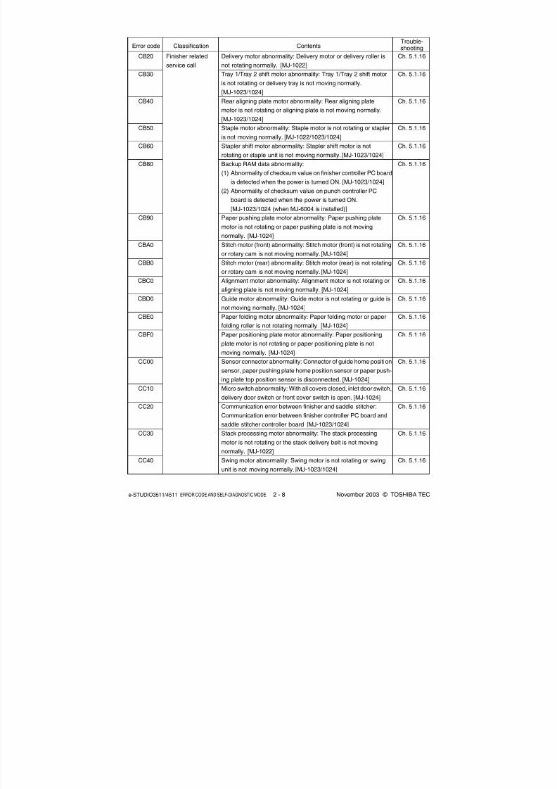
CB20
CB30
CB40
CB50
CB60
CB80
CB90
CBA0
CBB0
CBC0
CBD0
CBE0
CBF0
CC00
CC10
CC20
CC30
CC40
Delivery motor abnormality: Delivery motor or delivery roller is
not rotating normally. [MJ-1022]
Tray 1/Tray 2 shift motor abnormality: Tray 1/Tray 2 shift motor
is not rotating or delivery tray is not moving normally.
[MJ-1023/1024]
Rear aligning plate motor abnormality: Rear aligning plate
motor is not rotating or aligning plate is not moving normally.
[MJ-1023/1024]
Staple motor abnormality: Staple motor is not rotating or stapler
is not moving normally. [MJ-1022/1023/1024]
Stapler shift motor abnormality: Stapler shift motor is not
rotating or staple unit is not moving normally. [MJ-1023/1024]
Backup RAM data abnormality:
(1) Abnormality of checksum value on finisher controller PC board
is detected when the power is turned ON. [MJ-1023/1024]
(2) Abnormality of checksum value on punch controller PC
board is detected when the power is turned ON.
[MJ-1023/1024 (when MJ-6004 is installed)]
Paper pushing plate motor abnormality: Paper pushing plate
motor is not rotating or paper pushing plate is not moving
normally. [MJ-1024]
Stitch motor (front) abnormality: Stitch motor (front) is not rotating
or rotary cam is not moving normally. [MJ-1024]
Stitch motor (rear) abnormality: Stitch motor (rear) is not rotating
or rotary cam is not moving normally. [MJ-1024]
Alignment motor abnormality: Alignment motor is not rotating or
aligning plate is not moving normally. [MJ-1024]
Guide motor abnormality: Guide motor is not rotating or guide is
not moving normally. [MJ-1024]
Paper folding motor abnormality: Paper folding motor or paper
folding roller is not rotating normally. [MJ-1024]
Paper positioning plate motor abnormality: Paper positioning
plate motor is not rotating or paper positioning plate is not
moving normally. [MJ-1024]
Sensor connector abnormality: Connector of guide home position
sensor, paper pushing plate home position sensor or paper push-
ing plate top position sensor is disconnected. [MJ-1024]
Micro switch abnormality: With all covers closed, inlet door switch,
delivery door switch or front cover switch is open. [MJ-1024]
Communication error between finisher and saddle stitcher:
Communication error between finisher controller PC board and
saddle stitcher controller board [MJ-1023/1024]
Stack processing motor abnormality: The stack processing
motor is not rotating or the stack delivery belt is not moving
normally. [MJ-1022]
Swing motor abnormality: Swing motor is not rotating or swing
unit is not moving normally. [MJ-1023/1024]
Trouble-shootingError code Classification Contents
Ch. 5.1.16
Ch. 5.1.16
Ch. 5.1.16
Ch. 5.1.16
Ch. 5.1.16
Ch. 5.1.16
Ch. 5.1.16
Ch. 5.1.16
Ch. 5.1.16
Ch. 5.1.16
Ch. 5.1.16
Ch. 5.1.16
Ch. 5.1.16
Ch. 5.1.16
Ch. 5.1.16
Ch. 5.1.16
Ch. 5.1.16
Ch. 5.1.16
Finisher related
service call

8/2/2019 ES-3511 Service Handbook
http://slidepdf.com/reader/full/es-3511-service-handbook 29/543
November 2003 © TOSHIBA TEC 2 - 9 e-STUDIO3511/4511 ERROR CODE AND SELF-DIAGNOSTIC MODE
CC50
CC60
CC80
CC90
CCA0
CCB0
CCD0
CCE0
CCF0
CE00
CE10
CE20
CE40
CE50
CE90
CEA0
CEB0
Horizontal registration motor abnormality: Horizontal registration
motor is not rotating or puncher is not shifting normally.
[MJ-1023/1024 (when MJ-6004 is installed)]
Punch motor abnormality: Punch motor is not rotating or
puncher is not shifting normally. [MJ-1023/1024 (when MJ-6004
is installed)]
Front alignment motor abnormality: Front alignment motor is not
rotating or front aligning plate is not moving normally. [MJ-1022]
Front aligning plate motor abnormality: Front aligning plate
motor is not rotating or aligning plate is not moving normally.
[MJ-1023/1024]
Upper stack tray lift motor abnormality: The upper stack tray lift
motor is not rotating or the upper stack tray is not moving
normally. [MJ-1022]
Lower stack tray lift motor abnormality: The lower stack tray lift
motor is not rotating or the lower stack tray is not moving
normally. [MJ-1022]
Rear jogging motor abnormality: The rear jogging motor is not
rotating or the rear jogging plate is not moving normally. [MJ-1022]
Stack ejection motor abnormality: Stack ejection motor or stack
ejection roller is not rotating normally. [MJ-1023/1024]
Paper trailing edge assist motor abnormality: Paper trailing
edge assist motor is not rotating or paper trailing edge assist is
not moving normally. [MJ-1023/1024]
Gear changing motor abnormality: Gear changing motor is not
rotating normally. [MJ-1023/1024]
Communication error between finisher and punch unit: Commu-
nication error between finisher controller PC board and punch
controller PC board [MJ-1023/1024 (when MJ-6004 is installed)]
Image quality sensor abnormality (OFF level): The output value
of this sensor is out of a specified range when sensor light
source is OFF.
Image quality sensor abnormality (no pattern level): The output
value of this sensor is out of a specified range when the image
quality control test pattern is not formed.
Image quality control test pattern abnormality: The test pattern
is not formed normally.
Temperature/humidity sensor abnormality: The output value of
this sensor is out of a specified range.
Drum thermistor abnormality: The output value of the drum
thermistor is out of a specified range.
Revolver home position detection abnormality: It cannot detect
that the revolver is at its home position.
Black developer unit lifting movement abnormality: The black
developer unit does not move up or down normally (lifting cam
does not operate normally).
Finisher related
service call
Image control
related service call
Copy process
related service call
Trouble-shootingError code Classification Contents
Ch. 5.1.16
Ch. 5.1.16
Ch. 5.1.16
Ch. 5.1.16
Ch. 5.1.16
Ch. 5.1.16
Ch. 5.1.16
Ch. 5.1.16
Ch. 5.1.16
Ch. 5.1.16
Ch. 5.1.17
Ch. 5.1.17
Ch. 5.1.17
Ch. 5.1.17
Ch. 5.1.17
Ch. 5.1.18
Ch. 5.1.18

8/2/2019 ES-3511 Service Handbook
http://slidepdf.com/reader/full/es-3511-service-handbook 30/543
e-STUDIO3511/4511 ERROR CODE AND SELF-DIAGNOSTIC MODE 2 - 10 November 2003 © TOSHIBA TEC
2nd transfer roller position detection abnormality: The 2nd
transfer roller does not contact/release normally.
Transfer belt position detection abnormality (normal speed):
The home position of the transfer belt cannot be detected.
Transfer belt position detection abnormality (when decelerating):
Reference position of the transfer belt cannot be detected.
Revolver motor abnormality: Revolver motor is not rotating or
revolver is not moving normally.
Toner density detection voltage abnormality: The output value of
the color auto-toner sensor in printing is out of a specified range.
Reference plate detection voltage abnormality: The output
value of the color auto-toner sensor against the reference plate
is out of a specified range at the light amount correction during
an auto-toner adjustment or when a print job has finished.
Light amount correction voltage abnormality: The light amount
correction is not finished normally during an auto-toner adjust-
ment or when a print job has finished, or the output value of the
sensor is out of a specified range when the light amount
correction has finished.
Color auto-toner sensor abnormality: The connection of the
color auto-toner sensor cannot be detected at the initialization,
or the output value of color auto-toner sensor when the revolver
starts rotating for initialization is out of a specified range.
Communication error between System-CPU and Engine-CPU
SRAM abnormality on the SYS board
NVRAM abnormality on the SYS board
SRAM and NVRAM abnormality on the SYS board
HDD format error: HDD cannot be initialized normally.
HDD unmounted: Connection of HDD cannot be detected.
HDD start error: HDD cannot become ‘Ready’ state.
HDD transfer time-out: Reading/writing cannot be performed in
the specified period of time.
HDD data error: Abnormality is detected in the data of HDD.
HDD other error
Point and Print partition damage
/SHR partition damage
/SHA partition damage
Communication error between System-CPU and Scanner-CPU
Scanner response abnormality
Database abnormality: Database is not operating normally.
SLG board abnormality
Ch. 5.1.18
Ch. 5.1.18
Ch. 5.1.18
Ch. 5.1.18
Ch. 5.1.19
Ch. 5.1.19
Ch. 5.1.19
Ch. 5.1.19
Ch. 5.1.12
Ch. 5.1.14
Ch. 5.1.14
Ch. 5.1.14
Ch. 5.1.20
Ch. 5.1.20
Ch. 5.1.20
Ch. 5.1.20
Ch. 5.1.20
Ch. 5.1.20
Ch. 5.1.20
Ch. 5.1.20
Ch. 5.1.20
Ch. 5.1.12
Ch. 5.1.12
Ch. 5.1.20
Ch. 5.1.14
CEC0
CEE0
CEE1
CEF0
CF20
CF30
CF40
CF50
F070
F090
F091
F092
F100
F101
F102
F103
F104
F105
F106
F107
F108
F110
F111
F120
F350
Copy process
related service call
Toner density
control related
service call
Communication
related service call
Circuit related
service call
Other service call
Communication
related service call
Other service call
Circuit related
service call
Trouble-shootingError code Classification Contents

8/2/2019 ES-3511 Service Handbook
http://slidepdf.com/reader/full/es-3511-service-handbook 31/543
November 2003 © TOSHIBA TEC 2 - 11 e-STUDIO3511/4511 ERROR CODE AND SELF-DIAGNOSTIC MODE
2.1.3 Error in Internet FAX / Scanning Function
(1) Internet FAX related error
System access abnormality
Insufficient memory
Message reception errorMessage transmission error
Invalid parameter
Exceeding file capacity
System management module access abnormality
Job control module access abnormality
Job control module access abnormality
Directory creation failure
File creation failure
File deletion failure
File access failure
Image conversion abnormalityHDD full failure during processing
Address Book reading failure
Memory acquiring failure
Terminal IP address unset
Terminal mail address unset
SMTP address unset
Server time time-out error
NIC time time-out error
NIC access error
SMTP server connection error
HOST NAME errorTerminal mail address error
Destination mail address error
System error
SMTP client OFF
Internet FAX transmission failure when processing E-mail job received
Onramp Gateway transmission failure
Internet FAX transmission failure when processing FAX job received
Job canceling
Power failure
Ch. 5.1.21 (1)
Ch. 5.1.21 (1)
Ch. 5.1.21 (1)Ch. 5.1.21 (1)
Ch. 5.1.21 (1)
Ch. 5.1.21 (1)
Ch. 5.1.21 (1)
Ch. 5.1.21 (1)
Ch. 5.1.21 (1)
Ch. 5.1.21 (1)
Ch. 5.1.21 (1)
Ch. 5.1.21 (1)
Ch. 5.1.21 (1)
Ch. 5.1.21 (1)Ch. 5.1.21 (1)
Ch. 5.1.21 (1)
Ch. 5.1.21 (1)
Ch. 5.1.21 (1)
Ch. 5.1.21 (1)
Ch. 5.1.21 (1)
Ch. 5.1.21 (1)
Ch. 5.1.21 (1)
Ch. 5.1.21 (1)
Ch. 5.1.21 (1)
Ch. 5.1.21 (1)Ch. 5.1.21 (1)
Ch. 5.1.21 (1)
Ch. 5.1.21 (1)
Ch. 5.1.21 (1)
Ch. 5.1.21 (1)
Ch. 5.1.21 (1)
Ch. 5.1.21 (1)
-
Ch. 5.1.21 (1)
1C10
1C11
1C121C13
1C14
1C15
1C20
1C21
1C22
1C30
1C31
1C32
1C33
1C401C60
1C61
1C62
1C63
1C64
1C65
1C66
1C67
1C68
1C69
1C6A1C6B
1C6C
1C6D
1C70
1C80
1C81
1C82
1CC0
1CC1
Trouble-shootingError code Contents

8/2/2019 ES-3511 Service Handbook
http://slidepdf.com/reader/full/es-3511-service-handbook 32/543
e-STUDIO3511/4511 ERROR CODE AND SELF-DIAGNOSTIC MODE 2 - 12 November 2003 © TOSHIBA TEC
HOST NAME error(RFC: 500)
Destination mail address error
(RFC: 500)
Terminal mail address error(RFC: 500)
HOST NAME error(RFC: 501)
Destination mail address error
(RFC: 501)
Terminal mail address error
(RFC: 501)
Destination mail address error
(RFC: 503)
HOST NAME error(RFC: 504)
Destination mail address error
(RFC: 550)Destination mail address error
(RFC: 551)
Terminal/Destination mail address error
(RFC: 552)
Destination mail address error
(RFC: 553)
Ch. 5.1.21 (2)
Ch. 5.1.21 (2)
Ch. 5.1.21 (2)
Ch. 5.1.21 (2)
Ch. 5.1.21 (2)
Ch. 5.1.21 (2)
Ch. 5.1.21 (2)
Ch. 5.1.21 (2)
2500
2501
2503
2504
2550
2551
2552
2553
Syntax error, command unrecognized
Syntax error in parameters or arguments
Bad sequence of commands
Command parameter not implemented
Mailbox unavailable
User not local
Insufficient system storage
Mailbox name not allowed
Trouble-shootingError code Contents
Message displayed in the TopAccessscreen
(2) RFC related error

8/2/2019 ES-3511 Service Handbook
http://slidepdf.com/reader/full/es-3511-service-handbook 33/543
November 2003 © TOSHIBA TEC 2 - 13 e-STUDIO3511/4511 ERROR CODE AND SELF-DIAGNOSTIC MODE
2B10
2B11
2B202B30
2B31
2B32
2B50
2B51
2B712B80
2B90
2BA0
2BB0
2BB1
2BC0
2BC1
2BD0
2BE0
2BF0
2BF1
2BF2
There was no applicable job.
Job status failed.
Failed to access file.Insufficient disk space.
Failed to access Electronic Filing.
Failed to print Electronic Filing
document.
Failed to process image.
Failed to process print image.
Document(s) expire(s) in a few daysHard Disk space for Electronic Filing
nearly full.
Insufficient Memory.
Invalid Box password specified.
Job canceled
Power failure occurred
System fatal error.
Failed to acquire resource.
Power failure occurred during e-Filing
restoring.Failed to get machine parameter.
Maximum number of page range is
reached.
Maximum number of document range is
reached.
Maximum number of folder range is
reached.
No applicable job error in job control
module
JOB status abnormality
File library function errorInsufficient disk space in /SHR partition
Status of specified Electronic Filing or
folder is undefined or being created/
deleted
Electronic Filing printing failure:
Specified document can not be printed
because of client’s access (being edited,
etc.).
Image library error
List library error
Documents expiring in a few days existHard disk space in /SHR partition is
nearly full (90%).
Insufficient memory capacity
Invalid Box password
Job canceling
Power failure
Fatal failure occurred
System management module resource
acquiring failure
Power failure occurred during restoring
of Electronic FilingMachine parameter reading failure
Exceeding maximum number of pages
Exceeding maximum number of docu-
ments
Exceeding maximum number of folders
Ch. 5.1.21 (3)
Ch. 5.1.21 (3)
Ch. 5.1.21 (3)Ch. 5.1.21 (3)
Ch. 5.1.21 (3)
Ch. 5.1.21 (3)
Ch. 5.1.21 (3)
Ch. 5.1.21 (3)
--
Ch. 5.1.21 (3)
Ch. 5.1.21 (3)
-
Ch. 5.1.21 (3)
Ch. 5.1.21 (3)
Ch. 5.1.21 (3)
Ch. 5.1.21 (3)
Ch.5.1.21 (3)
Ch.5.1.21 (3)
Ch.5.1.21 (3)
Ch.5.1.21 (3)
Trouble-shootingError code Contents
Message displayed in the TopAccessscreen
(3) Electronic Filing related error
04/05

8/2/2019 ES-3511 Service Handbook
http://slidepdf.com/reader/full/es-3511-service-handbook 34/543
e-STUDIO3511/4511 ERROR CODE AND SELF-DIAGNOSTIC MODE 2 - 14 November 2003 © TOSHIBA TEC
System access abnormality
Insufficient memory
Message reception error
Message transmission errorInvalid parameter
Exceeding file capacity
System management module access
abnormality
Job control module access abnormality
Job control module access abnormality
Directory creation failure
File creation failure
File deletion failure
File access failureImage conversion abnormality
HDD full failure during processing
Address Book reading failure
Memory acquiring failure
Terminal IP address unset
Terminal mail address unset
SMTP address unset
Server time time-out error
NIC time time-out error
NIC access errorSMTP server connection error
HOST NAME error (No RFC error)
Terminal mail address error
Destination mail address error
(No RFC error)
System error
SMTP client OFF
E-mail transmission failure when
processing E-mail job received
Process failure of FAX job received
Job cancelingPower failure
Ch. 5.1.21 (4)
Ch. 5.1.21 (4)
Ch. 5.1.21 (4)
Ch. 5.1.21 (4)Ch. 5.1.21 (4)
Ch. 5.1.21 (4)
Ch. 5.1.21 (4)
Ch. 5.1.21 (4)
Ch. 5.1.21 (4)
Ch. 5.1.21 (4)
Ch. 5.1.21 (4)
Ch. 5.1.21 (4)
Ch. 5.1.21 (4)Ch. 5.1.21 (4)
Ch. 5.1.21 (4)
Ch. 5.1.21 (4)
Ch. 5.1.21 (4)
Ch. 5.1.21 (4)
Ch. 5.1.21 (4)
Ch. 5.1.21 (4)
Ch. 5.1.21 (4)
Ch. 5.1.21 (4)
Ch. 5.1.21 (4)Ch. 5.1.21 (4)
Ch. 5.1.21 (4)
Ch. 5.1.21 (4)
Ch. 5.1.21 (4)
Ch. 5.1.21 (4)
Ch. 5.1.21 (4)
Ch. 5.1.21 (4)
Ch. 5.1.21 (4)
-Ch. 5.1.21 (4)
2C10
2C11
2C12
2C132C14
2C15
2C20
2C21
2C22
2C30
2C31
2C32
2C332C40
2C60
2C61
2C62
2C63
2C64
2C65
2C66
2C67
2C682C69
2C6A
2C6B
2C6C
2C6D
2C70
2C80
2C81
2CC02CC1
Illegal Job status
Not enough memory
Illegal Job status
Illegal Job statusInvalid parameter specified
Message size exceeded limit or
maximum size
Illegal Job status
Illegal Job status
Illegal Job status
Failed to create directory
Failed to create file
Failed to delete file
Failed to create fileFailed to convert image file format
Failed to process your Job. Insufficient
disk space.
Failed to read AddressBook
Not enough memory
Invalid Domain Address
Invalid Domain Address
Failed to connect to SMTP server
Failed to connect to SMTP server
Failed to send E-Mail message
Failed to send E-Mail messageFailed to connect to SMTP server
Failed to send E-Mail message
Invalid address specified in From: field
Invalid address specified in To: field
NIC system error
SMTP service is not available
Failed to process received E-mail job
Failed to process received Fax job
Job canceledPower failure occurred
Trouble-shootingError code Contents
Message displayed in the TopAccessscreen
(4) E-mail related error

8/2/2019 ES-3511 Service Handbook
http://slidepdf.com/reader/full/es-3511-service-handbook 35/543
November 2003 © TOSHIBA TEC 2 - 15 e-STUDIO3511/4511 ERROR CODE AND SELF-DIAGNOSTIC MODE
System access abnormality
Insufficient memory
Message reception error
Message transmission error
Invalid parameter
Exceeding document number
System management module access
abnormality
Job control module access abnormality
Job control module access abnormality
Directory creation failure
File creation failure
File deletion failure
File access failure
Image conversion abnormality
File library access abnormality
Invalid parameter
File server connection error
Invalid network path
Login failure
Exceeding documents in folder:
Creating new document is failed.
HDD full failure during processing
FTP service not available
File sharing service not available
Periodical deletion of scanned
documents completed properly.
Periodical deletion of transmitted FAX
documents completed properly.
Periodical deletion of received FAX
documents completed properly.
Manual deletion of scanned documents
completed properly.
Manual deletion of transmitted FAX
documents completed properly.
Manual deletion of received FAX
documents completed properly.
File deletion failure
Resource acquiring failure
Job canceling
Power failure
Ch. 5.1.21 (5)
Ch. 5.1.21 (5)
Ch. 5.1.21 (5)
Ch. 5.1.21 (5)
Ch. 5.1.21 (5)
Ch. 5.1.21 (5)
Ch. 5.1.21 (5)
Ch. 5.1.21 (5)
Ch. 5.1.21 (5)
Ch. 5.1.21 (5)
Ch. 5.1.21 (5)
Ch. 5.1.21 (5)
Ch. 5.1.21 (5)
Ch. 5.1.21 (5)
Ch. 5.1.21 (5)
Ch. 5.1.21 (5)
Ch. 5.1.21 (5)
Ch. 5.1.21 (5)
Ch. 5.1.21 (5)
Ch. 5.1.21 (5)
Ch. 5.1.21 (5)
Ch. 5.1.21 (5)
Ch. 5.1.21 (5)
-
-
-
-
-
-
Ch. 5.1.21 (5)
Ch. 5.1.21 (5)
-
Ch. 5.1.21 (5)
2D10
2D11
2D12
2D13
2D14
2D15
2D20
2D21
2D22
2D30
2D31
2D32
2D33
2D40
2D60
2D61
2D62
2D63
2D64
2D65
2D66
2D67
2D68
2DA0
2DA1
2DA2
2DA3
2DA4
2DA5
2DA6
2DA7
2DC0
2DC1
Illegal Job status
Not enough memory
Illegal Job status
Illegal Job status
Invalid parameter specified
There are too many documents in the
folder. Failed in creating new document.
Illegal Job status
Illegal Job status
Illegal Job status
Failed to create directory
Failed to create file
Failed to delete file
Failed to create file
Failed to convert image file format
Failed to copy file
Invalid parameter specified
Failed to connect to network destination.
Check destination path
Specified network path is invalid.
Check destination path
Logon to file server failed. Check
username and password
There are too many documents in the
folder. Failed in creating new document.
Failed to process your Job. Insufficientdisk space.
FTP service is not available
File Sharing service is not available
Expired scan documents deleted from
share folder.
Expired Sent Fax documents deleted
from shared folder.
Expired Received Fax documents
deleted from shared folder.
Scanned documents in shared folder
deleted upon user’s request.
Sent Fax Documents in shared folder
deleted upon user’s request.
Received Fax Documents in shared
folder deleted upon user’s request.
Failed to delete file.
Failed to acquire resource.
Job canceled
Power failure occurred
Trouble-shootingError code Contents
Message displayed in the TopAccessscreen
(5) File sharing related error

8/2/2019 ES-3511 Service Handbook
http://slidepdf.com/reader/full/es-3511-service-handbook 36/543
e-STUDIO3511/4511 ERROR CODE AND SELF-DIAGNOSTIC MODE 2 - 16 November 2003 © TOSHIBA TEC
E-mail MIME error
E-mail analysis error
Partial mail time-out error
Partial mail related error
Insufficient HDD capacity error
Warning of insufficient HDD capacity
Warning of partial mail interruption
Partial mail reception setting OFF
Ch. 5.1.21 (6)
Ch. 5.1.21 (6)
Ch. 5.1.21 (6)
Ch. 5.1.21 (6)
Ch. 5.1.21 (6)
Ch. 5.1.21 (6)
Ch. 5.1.21 (6)
Ch. 5.1.21 (6)
Ch. 5.1.21 (6)
Ch. 5.1.21 (6)
Ch. 5.1.21 (6)
Ch. 5.1.21 (6)
Ch. 5.1.21 (6)
Ch. 5.1.21 (6)
Ch. 5.1.21 (6)
Ch. 5.1.21 (6)
Ch. 5.1.21 (6)
Ch. 5.1.21 (6)
3A10
3A11
3A12
3A20
3A21
3A22
3A30
3A40
3A50
3A51
3A52
3A60
3A61
3A62
3A70
3A80
3A81
3A82
MIME Error has been detected in the
received mail.
MIME Error has been detected in the
received mail. This mail has beentransferred to the administrator.
MIME Error has been detected in the
received mail. This mail could not be
transferred to the administrator.
Analyze Error has been detected in the
received mail.
Analyze Error has been detected in the
received mail. This mail has been
transferred to the administrator.
Analyze Error has been detected in the
received mail. This mail could not be
transferred to the administrator.
Whole partial mails were not reached by
timeout.
Partial Mail Error has been detected in
the received mail.
HDD Full Error has been occurred in this
mail.
HDD Full Error has been occurred in this
mail. This mail has been transferred to
the administrator.
HDD Full Error has been occurred in this
mail. This mail could not be transferred
to the administrator.
HDD Full Warning has been occurred in
this mail.
HDD Full Warning has been occurred in
this mail. This mail could not be transferred
to the administrator.
HDD Full Warning has been occurred in
this mail. This mail could not be
transferred to the administrator.
Receiving partial mail was aborted since
the partial mail setting has been changedto Disable.
Partial mail was received during the
partial mail setting is disabled.
Partial mail was received during the partial
mail setting is disabled. This mail has been
transferred to the administrator.
Partial mail was received during the partial
mail setting is disabled. This mail could not
be transferred to the administrator.
Trouble-shootingError code Contents
Message displayed in the TopAccessscreen
(6) E-mail reception related error

8/2/2019 ES-3511 Service Handbook
http://slidepdf.com/reader/full/es-3511-service-handbook 37/543
November 2003 © TOSHIBA TEC 2 - 17 e-STUDIO3511/4511 ERROR CODE AND SELF-DIAGNOSTIC MODE
E-mail format error
Content-Type error
Charset error
E-mail decode error
TIFF analysis error
Ch. 5.1.21 (6)
Ch. 5.1.21 (6)
Ch. 5.1.21 (6)
Ch. 5.1.21 (6)
Ch. 5.1.21 (6)
Ch. 5.1.21 (6)
Ch. 5.1.21 (6)
Ch. 5.1.21 (6)
Ch. 5.1.21 (6)
Ch. 5.1.21 (6)
Ch. 5.1.21 (6)
Ch. 5.1.21 (6)
Ch. 5.1.21 (6)
Ch. 5.1.21 (6)
Ch. 5.1.21 (6)
Ch. 5.1.21 (6)
3B10
3B11
3B12
3B20
3B21
3B22
3B30
3B31
3B32
3B40
3B41
3B42
3C10
3C11
3C12
3C13
Format Error has been detected in the
received mail.
Format Error has been detected in the
received mail. This mail has been
transferred to the administrator.
Format Error has been detected in the
received mail. This mail could not be
transferred to the administrator.
Content-Type Error has been detected in
the received mail.
Content-Type Error has been detected in
the received mail. This mail has been
transferred to the administrator.
Content-Type Error has been detected in
the received mail. This mail could not be
transferred to the administrator.
Charset Error has been detected in the
received mail.
Charset Error has been detected in the
received mail. This mail has been
transferred to the administrator.
Charset Error has been detected in the
received mail. This mail could not be
transferred to the administrator.
Decode Error has been detected in the
received mail.
Decode Error has been detected in the
received mail. This mail has been
transferred to the administrator.
Decode Error has been detected in the
received mail. This mail could not be
transferred to the administrator.
Tiff Analyze Error has been detected in
the received mail.
Tiff Analyze Error has been detected in
the received mail. This mail has been
transferred to the administrator.
Tiff Analyze Error has been detected in
the received mail. This mail could not be
transferred to the administrator.
Tiff Analyze Error has been detected in
the received mail.
Trouble-shootingError code Contents
Message displayed in the TopAccessscreen

8/2/2019 ES-3511 Service Handbook
http://slidepdf.com/reader/full/es-3511-service-handbook 38/543
e-STUDIO3511/4511 ERROR CODE AND SELF-DIAGNOSTIC MODE 2 - 18 November 2003 © TOSHIBA TEC
TIFF compression error
TIFF resolution error
TIFF paper size error
Offramp destination error
Offramp security error
Ch. 5.1.21 (6)
Ch. 5.1.21 (6)
Ch. 5.1.21 (6)
Ch. 5.1.21 (6)
Ch. 5.1.21 (6)
Ch. 5.1.21 (6)
Ch. 5.1.21 (6)
Ch. 5.1.21 (6)
Ch. 5.1.21 (6)
Ch. 5.1.21 (6)
Ch. 5.1.21 (6)
Ch. 5.1.21 (6)
Ch. 5.1.21 (6)
Ch. 5.1.21 (6)
Ch. 5.1.21 (6)
3C20
3C21
3C22
3C30
3C31
3C32
3C40
3C41
3C42
3C50
3C51
3C52
3C60
3C61
3C62
Tiff Compression Error has been
detected in the received mail.
Tiff Compression Error has been
detected in the received mail. This mail
has been transferred to the administrator.
Tiff Compression Error has been detected
in the received mail. This mail could not be
transferred to the administrator.
Tiff Resolution Error has been detected
in the received mail.
Tiff Resolution Error has been detected
in the received mail. This mail has been
transferred to the administrator.
Tiff Resolution Error has been detected
in the received mail. This mail could not
be transferred to the administrator.
Tiff Paper Size Error has been detected
in the received mail.
Tiff Paper Size Error has been detected
in the received mail. This mail has been
transferred to the administrator.
Tiff Paper Size Error has been detected
in the received mail. This mail could not
be transferred to the administrator.
Offramp Destination Error has been
detected in the received mail.
Offramp Destination Error has been
detected in the received mail. This mail
has been transferred to the administrator.
Offramp Destination Error has been
detected in the received mail. This mail
could not be transferred to the
administrator.
Offramp Security Error has been
detected in the received mail.
Offramp Security Error has been
detected in the received mail. This mail
has been transferred to the administrator.
Offramp Security Error has been detected
in the received mail. This mail could not be
transferred to the administrator.
Trouble-shootingError code Contents
Message displayed in the TopAccessscreen

8/2/2019 ES-3511 Service Handbook
http://slidepdf.com/reader/full/es-3511-service-handbook 39/543
November 2003 © TOSHIBA TEC 2 - 19 e-STUDIO3511/4511 ERROR CODE AND SELF-DIAGNOSTIC MODE
Power failure error
Destination address error
Offramp destination limitation error
FAX board error
POP3 server connection error
POP3 server connection time-out error
POP3 login error
File I/O error
Ch. 5.1.21 (6)
Ch. 5.1.21 (6)
Ch. 5.1.21 (6)
Ch. 5.1.21 (6)
Ch. 5.1.21 (6)
Ch. 5.1.21 (6)
Ch. 5.1.21 (6)
Ch. 5.1.21 (6)
Ch. 5.1.21 (6)
Ch. 5.1.21 (6)
Ch. 5.1.21 (6)
Ch. 5.1.21 (6)
3C70
3D10
3D20
3D30
3E10
3E20
3E30
3F00
3F10
3F20
3F30
3F40
Power Failure has been occurred in
Email receiving.
SMTP Destination Error has been
detected in the received mail. This mail
was deleted.
Offramp Destination limitation Error has
been detected in the received mail.
Fax Board Error has been occurred in
the received mail.
POP3 Connection Error has been
occurred in the received mail.
POP3 Connection Timeout Error has
been occurred in the received mail.
POP3 Login Error has been occurred in
the received mail.
File I/O Error has been occurred in this
mail. The mail could not be received until
File I/O is recovered.
Trouble-shootingError code Contents
Message displayed in the TopAccessscreen
2.1.4 Printer function error
Following codes are displayed at the end of the user name on the print job log screen (when GM-
1010/3010 or GM-2010 is installed)
Page memory size error - 1200 dpi network print is performed by the equipment
with 128 MB (standard) memory.
HDD full during print - Large quantity image data by private print or invalid network
print are saved in HDD.
Print job cancellation - Print job (copy, list print, network print) is deleted from the
print job screen.
Print job power failure - The power of the equipment is turned OFF during print job
(copy, list print, network print).
Ch. 5.1.21 (6)
Ch. 5.1.21 (6)
Ch. 5.1.21 (6)
Ch. 5.1.21 (6)
402F
4031
A221
A222
Trouble-shootingError code Contents
04/05

8/2/2019 ES-3511 Service Handbook
http://slidepdf.com/reader/full/es-3511-service-handbook 40/543
e-STUDIO3511/4511 ERROR CODE AND SELF-DIAGNOSTIC MODE 2 - 20 November 2003 © TOSHIBA TEC
A Paper source
0: Not selected 1: Bypass feed 2: LCF 3: PFP upper drawer 4: Unused 5: PFP lower drawer
6: Unused 7: Upper drawer 8: Lower drawer
B Paper size code
0: A5/ST 1: A5-R 2: ST-R 3: LT 4: A4 5: B5-R 6: LT-R 7: A4-R 8: OTHER/UNIV 9: B5
A: FOLIO/COMP B: LG C: B4 D: LD E: A3 F: 13"LG G: Unsed H: A6-R I: Post card J: 8.5"SQ
K: A3-wide L: 305×457 mm M: 8K N: 16K-R O: 16K Z: Not selected
C Sort mode/staple mode
0: Non-sort/Non-staple 1: Group 2: Sort 7: Front staple
8: Double staple 9: Rear staple A: Saddle stitchD ADF mode
0: Unused 1: AUTO FEED (SADF) 2: STACK FEED
E APS/AMS mode
0: Not selected 1: APS 2: AMS
F Duplex mode
0: Not selected 1: Book 2: Double-sided/Single-sided 4: Double-sided/Duplex copying
8: Single-sided/Duplex copying
G Unused
H Image shift
0: Unused 1: Book 2: Left 4: Right
I Editing
0: Unused 1: Masking 2: Trimming 3: Mirror image 4: Unused
J Edge erase/Dual-page
0: Unused 1: Edge erase 2: Dual-page 3: Edge erase & Dual-page
K Unused
L Function
0: Unused 1: Copying 2: FAX/Internet FAX transmission 3: FAX/Internet FAX/E-mail reception printing
4: Unused 5: Printing/List print 6: Scan/E-mail transmission
MMM Primary scanning reproduction ratio (Display in hexadecimal)
(Mx256)+(Mx16)+M
NNN Secondary scanning reproduction ratio (Display in hexadecimal)
(Nx256)+(Nx16)+N
O Color mode
0: Auto color 1: Full color 2: Black 3: Unused 4: Twin color copy 5: Gray scale
6: Unused 7: Image smoothing
<<Error history>>
In the setting mode (08-253), the latest twenty groups of error data will be displayed.
Display example
EA10 03 07 26 17 57 32 064 064 23621000000
Error code YY MM DD HH MM SS MMM NNN ABCDEFHIJLO
4 digits 12 digits (Year is indicated 3 digits 3 digits 11 digits
with its last two digits.)
04/09

8/2/2019 ES-3511 Service Handbook
http://slidepdf.com/reader/full/es-3511-service-handbook 41/543
November 2003 © TOSHIBA TEC 2 - 21 e-STUDIO3511/4511 ERROR CODE AND SELF-DIAGNOSTIC MODE
2.2 Self-diagnosis Modes
Mode
Control panel
check mode
Test mode
Test print
mode
Adjustment
mode
Setting mode
List print mode
PM support
mode
Firmware
update mode
Note:
To enter the desired mode, turn ON the power while two digital keys designated to each mode (e.g. [0]
and [5]) are pressed simultaneously.
<Operation procedure>
• Control panel check mode (01):
Notes:
1. A mode can be canceled by [POWER] OFF/ON when the LED is lit and the LCD is blinking.
2. Button Check Buttons with LED (Press to turn OFF the LED.)
Buttons without LED (Press to display the message on the control panel.)
Button on touch panel (Press to display the screen on the control panel at power-
ON.)
[0][1][POWER]
(LED lit/LCD blinking) [START]
[START]
(Button check)
[POWER] OFF/ON
(Exit)
For start
[0]+[1]+
[POWER]
[0]+[3]+
[POWER]
[0]+[4]+
[POWER]
[0]+[5]+
[POWER]
[0]+[8]+
[POWER]
[9]+[START]+
[POWER]
[6]+[START]+
[POWER]
[8]+[9]+
[POWER]
Contents
All LEDs on the control panel are lit, and all
the LCD pixels blink.
Checks the status of input/output signals.
Outputs the test patterns.
Adjusts various items.
Sets various items.
Prints out the data lists of the codes 05 and
08, PM support mode and pixel counter.
Clears each counter.
Performs updating of the system firmware.
For exit
[POWER]
OFF/ON
[POWER]
OFF/ON
[POWER]
OFF/ON
[POWER]
OFF/ON
[POWER]
OFF/ON
[POWER]
OFF/ON
[POWER]
OFF/ON
[POWER]
OFF/ON
Display
100% C A4
TEST MODE
100% P A4
TEST PRINT
100% A A4
TEST MODE
100% D
TEST MODE
100% UA A4
LIST PRINT
100% K
TEST MODE

8/2/2019 ES-3511 Service Handbook
http://slidepdf.com/reader/full/es-3511-service-handbook 42/543
e-STUDIO3511/4511 ERROR CODE AND SELF-DIAGNOSTIC MODE 2 - 22 November 2003 © TOSHIBA TEC
*1 Turn OFF the power after using the self-diagnosis mode, and leave the equipment to the user.
• Test mode (03): Refer to “2.2.1. Input check (test mode 03)” and “2.2.2. Output check (test mode 03)”.
• Test print mode (04): Refer to “2.2.3. Test print mode (04)”.
• Adjustment mode (05): Refer to “2.2.4. Adjustment mode (05)”.
• Setting mode (08): Refer to “2.2.5. Setting mode (08)”.
• List print mode (9S): The procedure varies depending on the code.
State transition diagram of self-diagnosis modes
[9] [START][POWER]
(Code)
101: Adjustment mode (05)102: Setting mode (08)
(Code)
103: PM support mode104: Stored information of pixel counter (toner cartridge reference)105: Stored information of pixel counter (service technician reference)106: Error history
[Digital keys]
Key in the firstcode to be printed
[START] [Digital keys]
Key in the lastcode to be printed
[START] [START]
List starts tobe printed
[POWER] OFF/ON
(Exit)
[6][START][POWER]
[POWER] OFF/ON(Exit)
(Code) [START](Operation started)
2: PM Support Screen
Warming upControl panelcheck mode Test mode Test print
modeAdjustment
modeSettingmode
List printmode
PM supportmode
Firmwareupdate mode
[POWER]ON
Normal
Ready
[POWER]OFF
To user
[0][1] [0][3] [0][4] [0][5] [0][8] [9][START] [6][START] [8][9]
*1
• PM support mode (6S):
• Firmware update mode (89): Refer to “6. FIRMWARE UPDATING”.

8/2/2019 ES-3511 Service Handbook
http://slidepdf.com/reader/full/es-3511-service-handbook 43/543
November 2003 © TOSHIBA TEC 2 - 23 e-STUDIO3511/4511 ERROR CODE AND SELF-DIAGNOSTIC MODE
2.2.1 Input check (Test mode 03)
The status of each input signal can be checked by pressing the [FAX] button, [COPY] button
and the digital keys in the test mode (03).
<Operation procedure>
Note:
Initialization is performed before the equipment enters the test mode.
[Example of display during input check]
Items to be checked and the condition of the equipment when the buttons [A] to [H] are highlighted are
listed in the following pages.
[0][3]
[POWER][POWER]OFF/ON
(Exit)[START]
[FAX]or
[COPY][Digital keys] (LCD ON)
[CLEAR]

8/2/2019 ES-3511 Service Handbook
http://slidepdf.com/reader/full/es-3511-service-handbook 44/543
e-STUDIO3511/4511 ERROR CODE AND SELF-DIAGNOSTIC MODE 2 - 24 November 2003 © TOSHIBA TEC
[FAX] button: OFF/[COPY] button: OFF ( [FAX] LED: OFF/[COPY] LED: OFF)
DigitalButton Items to check
Condition
key with highlighted button
A Bypass unit connection Not connected
B ADU connection Not connected
C —
[1]D LCF connection Not connectedE —
F —
G —
H LCF drawer detection switch Drawer not installed
A PFP upper drawer detection switch Drawer not installed
B —
C PFP upper drawer paper stock sensor Paper almost empty
[2]D PFP upper drawer feed sensor Paper present
E PFP connection Not connected
F PFP side cover open/close switch Cover opened
G PFP upper drawer empty sensor No paperH PFP upper drawer tray-up sensor Tray at upper limit position
A LCF tray bottom sensor Tray at bottom position
B LCF standby side paper misload detection sensor Properly loaded
C —
[3]D —
E —
F —
G —
H Paper stock sensor at LCF feed side Paper present
A PFP lower drawer detection switch Drawer not installed
B —
C PFP lower drawer paper stock sensor Paper almost empty
[4]D PFP lower drawer feed sensor Paper present
E PFP motor rotation status (Motor is rotating at output mode (03)) Abnormal rotation
F —
G PFP lower drawer empty sensor No paper
H PFP lower drawer tray-up sensor Tray at upper limit position
A LCF end fence home position sensor Fence home position
B LCF end fence stop position sensor Fence stop position
C Empty sensor at LCF standby side No paper
[5]D LCF side cover open/close switch Cover closed
E LCF motor rotation status (Motor is rotating at output mode (03)) Abnormal rotation
F LCF tray-up sensor Tray at upper limit positionG LCF feed sensor No paper
H Empty sensor at LCF feed side No paper
A Lower drawer detection switch Drawer not installed
B Upper drawer detection switch Drawer not installed
C Lower drawer paper stock sensor Paper almost empty
[6]D Upper drawer paper stock sensor Paper almost empty
E Lower drawer empty sensor No paper
F Upper drawer empty sensor No paper
G Lower drawer tray-up sensor Tray at upper limit position
H Upper drawer tray-up sensor Tray at upper limit position

8/2/2019 ES-3511 Service Handbook
http://slidepdf.com/reader/full/es-3511-service-handbook 45/543
November 2003 © TOSHIBA TEC 2 - 25 e-STUDIO3511/4511 ERROR CODE AND SELF-DIAGNOSTIC MODE
A —
B —
C —
[7]D —
E Side cover open/close switch Cover opened
F Front cover opening/closing switch Cover opened
G —
H Exit sensor Paper present
A Bypass feed paper width sensor 3 Refer to table 1
B Bypass feed paper width sensor 2 Refer to table 1
C Bypass feed paper width sensor 1 Refer to table 1
[8]D Bypass feed paper width sensor 0 Refer to table 1
E Bypass sensor No paper
F ADU opening/closing switch ADU opened
G ADU exit sensor Paper present
H ADU entrance sensor Paper present
A —B —
C —
[9]D —
E —
F Key copy counter connection Not connected
G —
H Paper clinging detection sensor No paper
A —
B —
C —
[0]
D —
E —
F —
G —
H —
DigitalButton Items to check
Condition
key with highlighted button
Table 1. Relation between the status of the bypass paper width sensor and paper size (width).
Bypass paper width sensorPaper width size
3 2 1 0
0 1 1 1 A3/LD
1 0 1 1 A4-R/LT-R
1 1 0 1 A5-R/ST-R
1 1 1 0 Card size
0 0 1 1 B4-R/LG
1 0 0 1 B5-R

8/2/2019 ES-3511 Service Handbook
http://slidepdf.com/reader/full/es-3511-service-handbook 46/543
e-STUDIO3511/4511 ERROR CODE AND SELF-DIAGNOSTIC MODE 2 - 26 November 2003 © TOSHIBA TEC
A 2nd transfer roller position detection sensor Released
B Black developer contact timing detection sensor Releasing movement
C Black developer contact position detection sensor Released position
D Main motor rotation status Abnormal rotation
(Motor is rotating at Output Mode (03))
[1]E Developer motor rotation status Abnormal rotation
(Motor is rotating at Output Mode (03))
F Transport motor rotation status Abnormal rotation
(Motor is rotating at Output Mode (03))
G Polygonal motor rotation status Abnormal rotation
(Motor is rotating at Output Mode (03))
H 24V Power supply Power OFF
A IPC board connection Not connected
B Color toner cartridge sensor Normally
C Revolver home position sensor Home position
[2]D —
E —
F Toner bag full detection sensor Toner bag full
G Black auto-toner sensor connection Not connected
H —
A —
B —
C —
[3]D —
E —
F —
G Lower drawer feed sensor No paper
H Upper drawer feed sensor Paper present
A —
B —
C —
[4]D —
E Bridge unit connection Not connected
F Color auto-toner sensor connection Not connected
G —
H —
A —
B —C —
[5]D —
E —
F RADF connection RADF connected
G Platen sensor Platen cover opened
H Carriage home position sensor Home position
DigitalButton Items to check
Condition
key with highlighted button
[FAX] button: ON/[COPY] button: OFF ([FAX] LED: ON/[COPY] LED: OFF)

8/2/2019 ES-3511 Service Handbook
http://slidepdf.com/reader/full/es-3511-service-handbook 47/543
November 2003 © TOSHIBA TEC 2 - 27 e-STUDIO3511/4511 ERROR CODE AND SELF-DIAGNOSTIC MODE
A —
B —
C —
[6]D APS sensor (APS-R) No original
E APS sensor (APS-C) No original
F APS sensor (APS-3) No original
G APS sensor (APS-2) No original
H APS sensor (APS-1) No original
A RADF tray sensor Original present
B RADF empty sensor Original present
C RADF jam access cover switch Cover opened
[7]D RADF open/close sensor RADF opened
E RADF exit sensor Original present
F RADF reverse sensor Original present
G RADF read sensor Original present
H RADF registration sensor Original present
A —B —
C —
[8]D —
E RADF original length sensor Original present
F RADF original width sensor 1 Original present
G RADF original width sensor 2 Original present
H RADF original width sensor 3 Original present
A Black toner cartridge switch Cartridge not installed
B —
C —
[9]
D Bypass feed sensor No paper
E Registration sensor Paper present
F —
G —
H Transfer belt home position sensor Home position
A Bridge unit transport sensor 2 Paper present
B Bridge unit cover open/close detection switch Cover opened
C Bridge unit transport sensor 1 Paper present
[0]D Bridge unit paper full detection sensor Paper not full
E —
F Charger cleaner front position detection switch Cleaner home position
G Charger cleaner rear position detection switch Cleaner rear position
H —
DigitalButton Items to check
Condition
key with highlighted button
[FAX] button: OFF/[COPY] button: ON ([FAX] LED: OFF/[COPY] LED: ON)
Items to check
Temperature/humidity sensor
Temperature/humidity sensor
Drum thermistor
Display on the touch panel
Displays the temperature inside the equipment. (Unit: °C)
Displays the humidity inside the equipment. (Unit: %RH)
Displays the temperature near the drum surface. (Unit: °C)
Digital
key
[1]
[2]
[3]

8/2/2019 ES-3511 Service Handbook
http://slidepdf.com/reader/full/es-3511-service-handbook 48/543
e-STUDIO3511/4511 ERROR CODE AND SELF-DIAGNOSTIC MODE 2 - 28 November 2003 © TOSHIBA TEC
2.2.2 Output check (test mode 03)
Status of the output signals can be checked by entering the following codes in the test mode 03.
<Operation procedure>
Procedure 1
Procedure 2
Procedure 3
Procedure 4
[0][3][POWER]
[POWER]OFF/ON(Exit)
[START][START](Code)Operation
ONStopcode
OperationOFF( )( )( )
[0][3]
[POWER]
[POWER]OFF/ON
(Exit)[START](Code)
Operation
One direction ( )( ) [CLEAR]Test mode
standby
[0][3][POWER]
[POWER]OFF/ON
(Exit)
[START][START](Code)Operation
OFF( ) ( )OperationON( ) [CLEAR] Test mode
standby
[0][3][POWER]
[POWER]OFF[START](Code)

8/2/2019 ES-3511 Service Handbook
http://slidepdf.com/reader/full/es-3511-service-handbook 49/543
November 2003 © TOSHIBA TEC 2 - 29 e-STUDIO3511/4511 ERROR CODE AND SELF-DIAGNOSTIC MODE
101 Main motor ON (Operational without black 151 Code No.101 function OFF 1
developer unit)
102 Toner motor K (normal rotation) ON 152 Code No.102 function OFF 1
103 Polygonal motor (600dpi) ON 153 Code No.103 function OFF 1
108 Registration clutch ON 158 Code No.108 function OFF 1
109 PFP motor ON 159 Code No.109 function OFF 1
110 ADU motor ON 160 Code No.110 function OFF 1
112 Developer motor ON (Operational with black 162 Code No.112 function OFF 1
developer unit)
115 Drum cleaning brush motor ON 165 Code No.115 function OFF 1
116 Transfer belt cleaner auger motor ON 166 Code No.116 function OFF 1
118 Laser ON 168 Code No.118 function OFF 1
120 Exit motor (normal rotation) ON 170 Code No.120 function OFF 1
121 Exit motor (reversal rotation) ON 171 Code No.121 function OFF 1
122 LCF motor ON 172 Code No.122 function OFF 1
123 Transport motor ON 173 Code No.123 function OFF 1
124 Toner motor K (reversal rotation) ON 174 Code No.124 function OFF 1
125 Color auto-toner sensor shutter solenoid ON 175 Code No.125 function OFF 1
(open)
126 Color auto-toner sensor LED ON 176 Code No.126 function OFF 1
201 Upper drawer feed clutch ON/OFF 3
202 Lower drawer feed clutch ON/OFF 3
203 Lower transport clutch (high speed) ON/OFF 3
204 Bypass feed clutch ON/OFF 3
205 Lower transport clutch (low speed) ON/OFF 3
206 LCF pickup solenoid ON/OFF 3
207 LCF end fence reciprocating movement 2
208 LCF end fence motor ON/OFF 3
209 LCF feed clutch ON/OFF 3210 LCF transport clutch ON/OFF 3
218 Key copy counter count up 2
222 ADU clutch ON/OFF 3
225 PFP transport clutch ON/OFF 3
226 PFP upper drawer feed clutch ON/OFF 3
228 PFP lower drawer feed clutch ON/OFF 3
232 Bridge unit gate solenoid ON/OFF 3
235 Discharge LED ON/OFF 3
241 IH board cooling fan (low speed) ON/OFF 3
242 Upper drawer tray-up motor ON (tray up) 2
243 Lower drawer tray-up motor ON (tray up) 2
248 Developer bias (Black) [+DC] ON/OFF 3
249 Developer bias (Black) [-DC] ON/OFF 3
252 Main charger ON/OFF 3
261 Scan motor ON (Automatically stops at limit position, speed can be changed by using ZOOM button) 2
264 SLG board cooling fan / Scanner unit cooling fan ON (high/low speed) 1
265 SLG board cooling fan / Scanner unit cooling fan OFF 1
267 Scanner exposure lamp ON/OFF 3
268 Laser unit cooling fan (high speed) ON/OFF 3
271 LCF tray-up motor UP/DOWN 2
278 PFP upper drawer tray-up motor ON (tray up) 2
Code Function Code Function Procedure

8/2/2019 ES-3511 Service Handbook
http://slidepdf.com/reader/full/es-3511-service-handbook 50/543
e-STUDIO3511/4511 ERROR CODE AND SELF-DIAGNOSTIC MODE 2 - 30 November 2003 © TOSHIBA TEC
Code Function Procedure
280 PFP lower drawer tray-up motor ON (tray up) 2
281 RADF feed motor ON/OFF (normal rotation) 3
282 RADF feed motor ON/OFF (reverse rotation) 3
283 RADF read motor ON/OFF (normal rotation) 3
284 RADF reverse motor ON/OFF (normal rotation) 3
285 RADF reverse motor ON/OFF (reverse rotation) 3
294 RADF reverse solenoid ON/OFF 3
295 Power OFF mode (for 200V series) 4
297 RADF fan motor ON/OFF 3
410 Power supply cooling fan (low speed) ON/OFF 3
411 Power supply cooling fan (high speed) ON/OFF 3
412 Internal cooling fan ON/OFF (low speed) 3
413 Internal cooling fan ON/OFF (high speed) 3
416 IH board cooling fan (high speed) ON/OFF 3
417 Ozone exhaust fan (low speed) ON/OFF 3
418 Ozone exhaust fan (high speed) ON/OFF 3
419 Developer bias (Black) [AC] ON/OFF 3
420 Developer bias (Color) [+DC] ON/OFF 3
421 Developer bias (Color) [-DC1] ON/OFF 3
422 Developer bias (Color) [AC] ON/OFF 3
424 1st transfer roller bias [+] ON/OFF 3
425 1st transfer roller bias [-] ON/OFF 3
426 2nd transfer roller bias [+] ON/OFF 3
427 2nd transfer roller bias [-] ON/OFF 3
428 Drum cleaning blade bias ON/OFF 3
430 Image quality sensor shutter solenoid ON/OFF 3
431 Color developer drive clutch ON/OFF 3
432 Black developer drive clutch ON/OFF 3
433 Black developer lifting clutch ON/OFF 3435 2nd transfer roller contact clutch ON/OFF 3
437 Transfer belt cleaner clutch ON/OFF 3
439 Upper transport clutch (high speed) ON/OFF 3
440 Upper transport clutch (low speed) ON/OFF 3
442 Color developer toner supply clutch ON/OFF 3
450 Revolver motor ON/OFF (printing operation) 3
451 Revolver motor operation (at standby position) 2
452 Revolver motor operation (at toner cartridge Y access position) 2
453 Revolver motor operation (at toner cartridge M access position) 2
454 Revolver motor operation (at toner cartridge C access position) 2
455 Revolver motor operation (at developer unit Y access position) 2
456 Revolver motor operation (at developer unit M access position) 2
457 Revolver motor operation (at developer unit C access position) 2
458 Revolver motor operation (at home position) 2
459 Revolver motor operation (at developing position) 2
460 Black developer unit lifting movement ON/OFF (continuous lifting movement) 3
461 Charger cleaner motor movement (one reciprocating movement) 2
04/05

8/2/2019 ES-3511 Service Handbook
http://slidepdf.com/reader/full/es-3511-service-handbook 51/543
November 2003 © TOSHIBA TEC 2 - 31 e-STUDIO3511/4511 ERROR CODE AND SELF-DIAGNOSTIC MODE
2.2.3 Test print mode (test mode 04)
The embedded test pattern can be printed out by keying in the following codes in the test print
mode (04).
<Procedure 1>
Code
142
204
219
220
231
237
262
270
[0][4]
[POWER]
[POWER] OFF/ON
(Exit)(Code) [START]
Operation
Continuous
test printing[CLEAR]( )
Notes:
1. When an error occurs, it is indicated on the panel, but the recovery operation is not performed.
Turn OFF the power and then back ON to clear the error.
2. During test printing, the [CLEAR] button is disabled when “Wait adding toner” is displayed.
<Procedure 2>
[0][4][POWER]
[POWER] OFF/ON(Exit)
(Code) Colorselection
[START] [START] [CLEAR]
[CLEAR]
OperationContinuoustest printing(
( ()
Remarks
1
2
2
2
2
2
2
2
Types of test pattern
Grid pattern (black)
Grid pattern (color)
6% test pattern
8% test pattern
Secondary scanning direction 33 gradation steps
Halftone
Pattern for jitter evaluation (4 lines ON / 4 lines OFF)
Image quality control test pattern
Remarks
Pattern width: 2 dots, Pitch: 10 mm
Pattern width: 1 dot, Pitch: 10 mm
3 pixels standard, Width: 10 mm
1 pixel standard, for color deviation
correction
For checking the image quality
control

8/2/2019 ES-3511 Service Handbook
http://slidepdf.com/reader/full/es-3511-service-handbook 52/543
e-STUDIO3511/4511 ERROR CODE AND SELF-DIAGNOSTIC MODE 2 - 32 November 2003 © TOSHIBA TEC
Procedure 5
Procedure 2
2.2.4 Adjustment mode (05)
Items in the adjustment mode list in the following pages can be corrected or changed in this
adjustment mode (05). Turn ON the power with pressing the digital keys [0] and [5] simultaneously
in order to enter this mode.
Procedure 4
Procedure 1
Procedure 3
[0][5]
[POWER]
[POWER]
OFF/ON
(Exit)
[Digital key]
(Code)[START]
[CANCEL]
[Digital key]
*[FUNCTION CLEAR]
(Key in a value)
[CLEAR]
(Corrects value)
[ENTER]
or
[INTERRUPT]
(Stores value in RAM)
([FAX] [START])
(Test copy)
*Press [FUNCTION CLEAR] to enter minus (-).
[0][5]
[POWER]
[POWER]
OFF/ON
(Exit)
[START][ENTER]
or
[INTERRUPT]
(value unchangeable)
([FAX] [START])
(Test copy)
Value
displayed( )[Digital key]
(Code)
[0][5]
[POWER]
[POWER]
OFF/ON
(Exit)
[Digital key]
(Code)[START]
[CANCEL]
[UP]
or
[DOWN]
(Adjust a value)
[CLEAR](Corrects value)
[ENTER]
or
[INTERRUPT]
(Stores value in RAM)
([FAX] [START])
(Test copy)
[0][5]
[POWER]
[POWER]
OFF/ON
(Exit)
[Digital key]
(Code)
[Digital key]
*[FUNCTION CLEAR]
[START] [START][Digital key]
(Sub code)
[CLEAR]
(Corrects value)
[CLEAR]
(Corrects value)
[ENTER]
or
[INTERRUPT]
*Press [FUNCTION CLEAR] to enter minus (-).
(Key in a value) Stores value
in RAM( )
[FAX]
[START]
(Test copy)
( )
[CANCEL]
[START]
[0][5]
[POWER]
[POWER]
OFF/ON
(Exit)
[Digital key]
(Code)[START]
[CANCEL] or [CLEAR]
[ENTER]
or
[INTERRUPT]
Stores value
in RAM( )
[FAX]
[START]
(Test copy)
( )Automatic
adjustment
[UP]
or
[DOWN]
(Adjust a value)
( )

8/2/2019 ES-3511 Service Handbook
http://slidepdf.com/reader/full/es-3511-service-handbook 53/543
November 2003 © TOSHIBA TEC 2 - 33 e-STUDIO3511/4511 ERROR CODE AND SELF-DIAGNOSTIC MODE
Procedure 14
Procedure 10
Procedure 6
[0][5]
[POWER]
[POWER]OFF/ON
(Exit)[Digital key]
(Code)[START] ( )Automatic
adjustment ([FAX] [START])(Test copy)
*[CANCEL] or [CLEAR]
[0][5]
[POWER]
[POWER]
OFF/ON
(Exit)
[Digital key]
(Code)
[Digital key]
(Sub code)[START] [START][START]
[ENTER] or [INTERRUPT]
(Value unchangeable)
( )Value
displayed
[0][5]
[POWER]
[POWER]
OFF/ON
(Exit)
[Digital key]
(Code)[START] [START][Digital key]
(Sub code)
[CANCEL]
(Corrects value)
[CLEAR]
(Corrects value)
[ENTER]
or
[INTERRUPT]
Stores valuein RAM( )
[FAX]
[START]
(Test copy)
( )[UP] or [DOWN]
(Adjust a value)
[0][5]
[POWER]
[POWER]
OFF/ON
(Exit)
[Digital key]
(Code)[START] ( )Automatic
adjustment
[FAX]
[START]
(Test copy)*[CANCEL] or [CLEAR]
[CANCEL]
( ) ( )[ENTER]
Stores value
in RAM
Procedure 7
Note:
The fuser roller temperature control at the adjustment mode is different from that at the normal state.
Therefore, the problem of fusing efficiency may be occurred in the test copy at the adjustment mode.
In that case, turn ON the power normally, leave the equipment for approx. 3 minutes after it has
become ready state and then start up the adjustment mode again.
* When the automatic adjustment ends abnormally, an error message is displayed.
* Return to standby screen by pressing the [CANCEL] or [CLEAR] button.
* When the automatic adjustment ends abnormally, an error message is displayed.
* Return to standby screen by pressing the [CANCEL] or [CLEAR] button.

8/2/2019 ES-3511 Service Handbook
http://slidepdf.com/reader/full/es-3511-service-handbook 54/543
e-STUDIO3511/4511 ERROR CODE AND SELF-DIAGNOSTIC MODE 2 - 34 November 2003 © TOSHIBA TEC
Code
1
3
4
5
6
7
10
12
13
14
15
47
48
49
50
51
52
55
56
57
58
59
60
62
63
64
Types of test pattern
Grid pattern (Black)
Grid pattern (Black/Duplex printing)
For gamma adjustment (Color/Black integrated pattern)
For gamma adjustment (Color)
For gamma adjustment (Black)
For gamma adjustment (Color)
For gamma adjustment (Black)
Secondary scanning direction 33 gradation steps (Y)
Secondary scanning direction 33 gradation steps (M)
Secondary scanning direction 33 gradation steps (C)
Secondary scanning direction 33 gradation steps (K)
Gamma adjustment for printer (PS/ 600 x 600 dpi)
Gamma adjustment for printer (PS/ 1,200 x 600 dpi)
Gamma adjustment for printer (PCL/ 600 x 600 dpi)
Gamma adjustment for printer (PCL/ 1,200 x 600 dpi)
Gamma checking for printer (PS/ 600 x 600 dpi)
Gamma checking for printer (PS/ 1,200 x 600 dpi)
Grid pattern (Full Color / Thick paper 2)
Grid pattern (Full Color / Thick paper 3)
Grid pattern (Full Color / OHP)
Grid pattern (Black / Thick paper 2)
Grid pattern (Black / Thick paper 3)
Grid pattern (Black / OHP)
For color deviation correction (Full Color)
For color deviation correction (Full Color)
For color deviation correction (Full Color)
Test print pattern in Adjustment Mode (05)
Operation: One test print is printed out when the [FAX] button is pressed after the code is keyed in at
Standby Screen.
Remarks
Refer to 3.4.3 Printer related adjustment
Refer to 3.4.3 Printer related adjustment
Refer to 3.5.1 Automatic gamma adjustment
Refer to 3.5.1 Automatic gamma adjustment
For checking the gradation reproduction
For checking the gradation reproduction
Refer to 3.5.1 Automatic gamma adjustment
For checking the image of printer section
For checking the image of printer section
For checking the image of printer section
For checking the image of printer section
Refer to 3.6.1 Automatic gamma adjustment
Refer to 3.6.1 Automatic gamma adjustment
Refer to 3.6.1 Automatic gamma adjustment
Refer to 3.6.1 Automatic gamma adjustment
For checking the gradation reproduction
For checking the gradation reproduction
Refer to 3.4.2 Paper alignment at the
registration roller
Refer to 3.4.2 Paper alignment at the
registration roller
Refer to 3.4.2 Paper alignment at the
registration roller
Refer to 3.4.2 Paper alignment at the
registration roller
Refer to 3.4.2 Paper alignment at the
registration roller
Refer to 3.4.2 Paper alignment at the
registration roller
Only for A3/LD size
Only for A3/LD size
Only for A3/LD size
03/12

8/2/2019 ES-3511 Service Handbook
http://slidepdf.com/reader/full/es-3511-service-handbook 55/543
November 2003 © TOSHIBA TEC 2 - 35 e-STUDIO3511/4511 ERROR CODE AND SELF-DIAGNOSTIC MODE
Initialization of
color auto-toner
sensor light
amount correction
target value
Initialization of color auto-
toner sensor light amount
correction target value
Enforced correction of color
auto-toner sensor light
amount
1st transfer roller bias output
adjustment
(When not transferred)
1st transfer roller
bias output
adjustment
(Image quality
control test
pattern)
1st transfer roller
bias output
adjustment
200
201
202
203
204
206
207
208
210
211-0
211-1
211-2
211-3
212
214
215
216
217
Devel-
opment
Devel-
opment
Devel-
opment
Transfer
Transfer
Transfer
All
(Y,M,C,K)
Y
M
C
K
YMC
Y
M
C
K
Plain
paper
Thick
paper 1
Thick
paper 2
Thick
paper 3
OHP film
ALL
ALL
ALL
ALL
ALL
ALL
ALL
(color)
ALL
(color)
ALL
ALL
(color)
ALL
(color)
ALL
(color)
ALL
(color)
ALL
(black)
ALL
(black)
ALL
(black)
ALL
(black)
ALL
(black)
-
<0-255>
-
<0-255>
-
<0-255>
-
<0-255>
-
<0-255>
-
<0-255>-
-
225
<0-225>
140
<0-225>
140
<0-225>
140
<0-225>
148
<0-225>
135
<0-225>
135
<0-225>
135
<0-225>
135
<0-225>
135
<0-225>
M
M
M
M
M
M
M
M
M
M
M
M
M
M
M
M
M
M
The value starts changing approx. 3
minutes after this adjustment started.
The value is automatically set during
this adjustment (approx. 2 minutes).
(As the value increases, the sensor
output increases correspondingly.)
( Chapter 3.2)
Initializes the color auto-toner sensor
light amount correction target value.
Performs the color auto-toner sensor
light amount correction forcibly.
When the value decreases, the 1st
transfer roller bias output increases.
The adjustment value becomes
effective when the Setting Mode (08-
541, 549 and 551) is 0 (invalid).
When the value decreases, the 1st
transfer roller bias output increases.
The adjustment value becomes
effective when the Setting Mode (08-
541, 549 and 551) is 0 (invalid).
When the value decreases, the 1st
transfer roller bias output increases.
The adjustment value becomes
effective when the Setting Mode (08-
541, 549 and 551) is 0 (invalid).
5
5
5
5
5
5
6
6
3
14
14
14
14
3
3
3
3
3
Adjustment mode (05)
CodeClassifi-cation Items
Func-tion
Default
<Acceptablevalue> RAM ContentsProce-
dure
Notes:
1. The digit after the hyphen in “Code” of the following table is a sub code.
2. In “RAM”, the NVRAM of the board in which the data of each code is stored is indicated. “M” stands for
the LGC board and “SYS” stands for the SYS board.
04/05

8/2/2019 ES-3511 Service Handbook
http://slidepdf.com/reader/full/es-3511-service-handbook 56/543
e-STUDIO3511/4511 ERROR CODE AND SELF-DIAGNOSTIC MODE 2 - 36 November 2003 © TOSHIBA TEC
When the value decreases, the 1st
transfer roller bias output increases.
The adjustment value becomes
effective when the Setting Mode (08-
541, 549 and 551) is 0 (invalid).
When the value decreases, the 1st
transfer roller bias output increases.
The adjustment value becomes
effective when the Setting Mode (08-
541, 549 and 551) is 0 (invalid).
When the value decreases, the 1st
transfer roller bias output increases.
The adjustment value becomes
effective when the Setting Mode (08-
541, 549 and 551) is 0 (invalid).
When the value decreases, the 1st
transfer roller bias output increases.
The adjustment value becomes
effective when the Setting Mode (08-
541, 549 and 551) is 0 (invalid).
When the value decreases, the 1st
transfer roller bias output increases.
The adjustment value becomes
effective when the Setting Mode (08-
541, 549 and 551) is 0 (invalid).
When the value decreases, the 2nd
transfer roller bias output increases.
When the value decreases, the 2nd
transfer roller bias output increases.
When the value decreases, the 2nd
transfer roller bias output increases.
14
14
14
14
14
14
14
14
14
14
14
14
14
14
14
14
14
14
14
14
3
3
3
135
<0-225>
140
<0-225>
145<0-225>
150
<0-225>
135
<0-225>
140
<0-225>
145
<0-225>
150
<0-225>
135
<0-225>
140
<0-225>
145
<0-225>
150
<0-225>
135
<0-225>
140
<0-225>
145
<0-225>
150
<0-225>
135
<0-225>
140
<0-225>
145
<0-225>
150
<0-225>
137
<0-158>
196
<159-255>
169
<159-255>
M
M
M
M
M
M
M
M
M
M
M
M
M
M
M
M
M
M
M
M
M
M
M
ALL
(color)
ALL
(color)
ALL
ALL
(color)
ALL
(color)
ALL
(color)
ALL
(color)
ALL
(color)
ALL
(color)
ALL
(color)
ALL
(color)
ALL
(color)
ALL
(color)
ALL
(color)
ALL
(color)
ALL
(color)
ALL
(color)
ALL
(color)
ALL
(color)
ALL
(color)
ALL
ALL
ALL
1st transfer roller
bias output
adjustment
(Plain paper)
1st transfer roller
bias output
adjustment
(Thick paper 1)
1st transfer roller
bias output
adjustment
(Thick paper 2)
1st transfer roller
bias output
adjustment
(Thick paper 3)
1st transfer roller
bias output
adjustment
(OHP film)
2nd transfer roller bias
output adjustment (Whencleaning the roller [+] )
2nd transfer roller bias
output adjustment (When
cleaning the roller [-] )
2nd transfer roller bias
output adjustment (Paper
interval/When not trans-
ferred)
218-0
218-1
218-2
218-3
220-0
220-1
220-2
220-3
221-0
221-1
221-2
221-3
222-0
222-1
222-2
222-3
223-0
223-1
223-2
223-3
224
225
226
Transfer
Transfer
Transfer
Transfer
Transfer
Transfer
Transfer
Transfer
Adjustment mode (05)
CodeClassifi-cation
ItemsFunc-tion
Default<Acceptable
value>RAM Contents
Proce-dure
Y
M
C
K
Y
M
C
K
Y
M
C
K
Y
M
C
K
Y
M
C
K

8/2/2019 ES-3511 Service Handbook
http://slidepdf.com/reader/full/es-3511-service-handbook 57/543
November 2003 © TOSHIBA TEC 2 - 37 e-STUDIO3511/4511 ERROR CODE AND SELF-DIAGNOSTIC MODE
2nd transfer roller
bias output
adjustment
(Plain paper)
2nd transfer roller
bias output
adjustment
(Thick paper 1)
2nd transfer roller bias
output (Thick paper 2)
2nd transfer roller bias
output (Thick paper 3)
2nd transfer roller bias
output (OHP film)
1st transfer roller bias
offsetting
2nd transfer rollerbias offsetting
adjustment
(Plain paper)
227-0
227-1
227-2
227-3
229-0
229-1
229-2
229-3
230-0
230-1
231-0
231-1
232-0
232-1
233
234-0
234-1
234-2
234-3
14
14
14
14
14
14
14
14
14
14
14
14
14
14
1
4
4
4
4
Transfer
Transfer
Transfer
Transfer
Transfer
Transfer
Transfer
ALL
(black)
ALL
(black)
ALL
(color)
ALL
(color)
ALL
(black)
ALL
(black)
ALL
(color)
ALL
(color)
ALL
(black)
ALL
(color)
ALL
(black)
ALL
(color)
ALL
(black)
ALL
(color)
ALL
(color)
ALL(black)
ALL
(black)
ALL
(color)
ALL
(color)
M
M
M
M
M
M
M
M
M
M
M
M
M
M
M
M
M
M
M
Single
side
Reverse
side at
duplexingSingle
side
Reverse
side at
duplexing
Single
side
Reverse
side at
duplexing
Single
side
Reverse
side at
duplexing
Singleside
Reverse
side at
duplexing
Single
side
Reverse
side at
duplexing
143
<0-158>
116
<0-158>
137
<0-158>
113
<0-158>
137
<0-158>
107
<0-158>
119
<0-158>
107
<0-158>
143
<0-158>
137
<0-158>
143
<0-158>
137
<0-158>
113
<0-158>
107
<0-158>
5
<0-10>
5<0-10>
5
<0-10>
5
<0-10>
5
<0-10>
When the value decreases, the 2nd
transfer roller bias output increases.
The adjustment value becomes
effective when the Setting Mode (08-
544, 549 and 551) is 0 (invalid).
When the value decreases, the 2nd
transfer roller bias output increases.
The adjustment value becomes
effective when the Setting Mode (08-
544, 549 and 551) is 0 (invalid).
When the value decreases, the 2nd
transfer roller bias output increases.
The adjustment value becomes
effective when the Setting Mode (08-
544, 549 and 551) is 0 (invalid).
When the value decreases, the 2nd
transfer roller bias output increases.
The adjustment value becomes
effective when the Setting Mode (08-
544, 549 and 551) is 0 (invalid).
When the value decreases, the 2nd
transfer roller bias output increases.
The adjustment value becomes
effective when the Setting Mode (08-
544, 549 and 551) is 0 (invalid).
Sets the offset amount of 1st transfer
roller bias.
0: -500V 1: -400V 2: -300V
3: -200V 4: -100V 5: 0V
6: +100V 7: +200V 8: +300V
9: +400V 10: +500V
Sets the offset amount of 2ndtransfer roller bias.
0: -500V 1: -400V 2: -300V
3: -200V 4: -100V 5: 0V
6: +100V 7: +200V 8: +300V
9: +400V 10: +500V
Adjustment mode (05)
CodeClassifi-cation
ItemsFunc-tion
Default<Acceptable
value>RAM Contents
Proce-dure

8/2/2019 ES-3511 Service Handbook
http://slidepdf.com/reader/full/es-3511-service-handbook 58/543
e-STUDIO3511/4511 ERROR CODE AND SELF-DIAGNOSTIC MODE 2 - 38 November 2003 © TOSHIBA TEC
2nd transfer roller
bias offsetting
adjustment (Thick
paper 1)
2nd transfer roller bias
offsetting adjustment
(Thick paper 2)
2nd transfer roller bias
offsetting adjustment
(Thick paper 3)
2nd transfer roller bias
offsetting adjustment
(OHP film)
Main charger grid
bias adjustment
1st transfer roller bias
offsetting
1st transfer roller
bias output
voltage
2nd transfer rollerbias output
voltage
Adjustment mode (05)
236-0
236-1
236-2
236-3
237-0
237-1
238-0
238-1
239-0
239-1
241
242
243
244
245
250
251
252
253
4
4
4
4
4
4
4
4
4
4
3
3
3
3
1
1
1
1
1
Transfer
Transfer
Transfer
Transfer
Main
charger
Transfer
Transfer
Transfer
ALL
(black)
ALL
(black)
ALL
(color)
ALL
(color)
ALL
(black)
ALL
(color)
ALL
(black)
ALL
(color)
ALL
(black)
ALL
(color)
ALL
ALL
ALL
ALL
ALL
(black)
ALL
ALL
ALL
ALL
M
M
M
M
M
M
M
M
M
M
M
M
M
M
M
M
M
M
M
Single
side
Reverse
side at
duplexingSingle
side
Reverse
side at
duplexing
Y
M
C
K
+Low
+High
+Low
+High
5
<0-10>
5
<0-10>
5
<0-10>
5
<0-10>
5
<0-10>
5
<0-10>
5
<0-10>
5
<0-10>
5
<0-10>
5
<0-10>
78
<0-255>
84
<0-255>
87
<0-255>
94
<0-255>
5
<0-10>
4000
<1800-
4400>
400
<0-500>
4800<4320-
5280>
516
<366-
666>
Sets the offset amount of 2nd
transfer roller bias.
0: -500V 1: -400V 2: -300V
3: -200V 4: -100V 5: 0V
6: +100V 7: +200V 8: +300V9: +400V 10: +500V
Sets the offsetting amount of 2nd
transfer roller bias.
0: -1,000 V 1: -800 V 2: -600 V
3: -400 V 4: -200 V 5: 0 V
6: +200 V 7: +400 V 8: +600 V
9: +800 V 10: +1,000 V
As the value increases, the trans-
former output increases. The
adjustment value becomes effective
only when the setting mode (08-549,
551, 556, 557) is 0 (invalid).
Sets the offsetting amount of 1st
transfer roller bias.
0: -500 V 1: -400 V 2: -300 V 3: -200 V
4: -100 V 5: 0 V 6: +100 V 7: +200 V
8: +300 V 9: +400 V 10: +500 V
Transformer output setting of the 1st
transfer roller bias.
When replacing the high-voltage
transformer, the values listed in
attached data sheet are entered.
(Unit: V)
Transformer output setting of the 2ndtransfer roller bias (plus output).
When replacing the high-voltage
transformer, the values listed in
attached data sheet are entered.
(Unit: V)
CodeClassifi-cation
ItemsFunc-tion
Default<Acceptable
value>RAM Contents
Proce-dure
04/05

8/2/2019 ES-3511 Service Handbook
http://slidepdf.com/reader/full/es-3511-service-handbook 59/543
November 2003 © TOSHIBA TEC 2 - 39 e-STUDIO3511/4511 ERROR CODE AND SELF-DIAGNOSTIC MODE
1
1
10
10
10
10
2
2
2
2
2
10
10
10
10
10
10
10
10
10
10
10
10
M
M
M
M
M
M
M
M
M
M
M
M
M
M
M
M
M
M
M
M
M
M
M
Transformer output setting of the 2nd
transfer roller bias (minus output).
When replacing the high-voltage
transformer, the values l isted in
attached data sheet are entered.(Unit: V)
Displays the value of 1st transfer
roller bias when printing is operated.
Displays the value of 1st transfer
roller bias when printing is operated.
Displays the value of 1st transfer
roller bias when printing is operated.
Displays the value of 1st transfer
roller bias when printing is operated.
Displays the value of 1st transfer
roller bias when printing is operated.
2nd transfer roller
bias output
voltage
1st transfer roller
bias actual value
display (Image
quality control test
pattern)
1st transfer roller
bias actual value
display
1st transfer roller
bias actual value
display
(Plain paper)
1st transfer roller
bias actual value
display
(Thick paper 1)
1st transfer roller
bias actual valuedisplay
(Thick paper 2)
254
255
262-0
262-1
262-2
262-3
263
265
266
267
268
269-0
269-1
269-2
269-3
271-0
271-1
271-2
271-3
272-0
272-1
272-2
272-3
Transfer
Transfer
Transfer
Transfer
Transfer
Transfer
ALL
ALL
ALL
(color)
ALL
(color)
ALL
(color)
ALL
(color)
ALL
(black)
ALL
(black)
ALL
(black)
ALL
(black)
ALL
(black)
ALL
(color)
ALL
(color)
ALL
(color)
ALL
(color)
ALL
(color)
ALL
(color)
ALL
(color)
ALL
(color)
ALL
(color)ALL
(color)
ALL
(color)
ALL
(color)
-110
<-9999-0>
-2000
<-9999-0>
140
<0-225>
140
<0-225>
140
<0-225>
148
<0-225>
135
<0-225>
135
<0-225>
135
<0-225>
135
<0-225>
135
<0-225>
135
<0-225>
140
<0-225>
145
<0-225>
150
<0-225>
135
<0-225>
140
<0-225>
145
<0-225>
150
<0-225>
135
<0-225>140
<0-225>
145
<0-225>
150
<0-225>
-Low
-High
Y
M
C
K
Plain
paper
Thick
paper 1
Thick
paper 2
Thick
paper 3
OHP
film
Y
M
C
K
Y
M
C
K
Y
M
C
K
Adjustment mode (05)
CodeClassifi-cation
ItemsFunc-tion
Default<Acceptable
value>RAM Contents
Proce-dure

8/2/2019 ES-3511 Service Handbook
http://slidepdf.com/reader/full/es-3511-service-handbook 60/543
e-STUDIO3511/4511 ERROR CODE AND SELF-DIAGNOSTIC MODE 2 - 40 November 2003 © TOSHIBA TEC
1st transfer roller
bias actual value
display
(Thick paper 3)
1st transfer roller
bias actual value
display (OHP film)
2nd transfer roller
bias actual value
(When cleaning
the roller)
2nd transfer roller
bias actual value
display
(Plain paper)
2nd transfer roller
bias actual value
display
(Thick paper 1)
Transfer belt cleaning unitcontact timing adjustment
Transfer belt cleaning unit
release timing adjustment
2nd transfer roller bias
offsetting adjustment
(Thick paper 2)
Y
M
C
K
Y
M
C
K
(+)
(-)
Single
side
Reverse
side at
duplexing
Single
side
Reverse
side at
duplexing
Single
side
Reverse
side at
duplexing
Single
side
Reverse
side at
duplexing
135
<0-225>
140
<0-225>
145<0-225>
150
<0-225>
135
<0-225>
140
<0-225>
145
<0-225>
150
<0-225>
137
<0-255>
196
<0-255>
143
<0-158>
116
<0-158>
137
<0-158>
113
<0-158>
137
<0-158>
107
<0-158>
119
<0-158>
107
<0-158>
141<88-168>
141
<88-168>
143
<0-158>
137
<0-158>
M
M
M
M
M
M
M
M
M
M
M
M
M
M
M
M
M
M
M
M
M
M
Displays the value of 1st transfer
roller bias when printing is operated.
Displays the value of 1st transfer
roller bias when printing is operated.
Displays the value of 2nd transfer
roller bias when printing is operated.
Displays the value of 2nd transfer
roller bias when printing is operated.
Displays the value of 2nd transfer
roller bias when printing is operated.
When the value increases, thecontact timing of transfer belt
cleaning unit is delayed.
When the value increases, the
release timing of transfer belt
cleaning unit is delayed.
Displays the value of 2nd transfer
roller bias when printing is operated.
ALL
(color)
ALL
(color)
ALL(color)
ALL
(color)
ALL
(color)
ALL
(color)
ALL
(color)
ALL
(color)
ALL
ALL
ALL
(black)
ALL
(black)
ALL
(color)
ALL
(color)
ALL
(black)
ALL
(black)
ALL
(color)
ALL
(color)
ALL
ALL
ALL
(black)
ALL
(color)
10
10
10
10
10
10
10
10
2
2
10
10
10
10
10
10
10
10
1
1
10
10
273-0
273-1
273-2
273-3
274-0
274-1
274-2
274-3
275
276
277-0
277-1
277-2
277-3
279-0
279-1
279-2
279-3
284
285
290-0
290-1
Transfer
Transfer
Transfer
Transfer
Transfer
Transfer
Transfer
Transfer
Adjustment mode (05)
CodeClassifi-cation
ItemsFunc-tion
Default<Acceptable
value>RAM Contents
Proce-dure
04/09

8/2/2019 ES-3511 Service Handbook
http://slidepdf.com/reader/full/es-3511-service-handbook 61/543
November 2003 © TOSHIBA TEC 2 - 41 e-STUDIO3511/4511 ERROR CODE AND SELF-DIAGNOSTIC MODE
2nd transfer roller bias
offsetting adjustment
(Thick paper 3)
2nd transfer roller biasoffsetting adjustment
(OHP film)
2nd transfer roller
bias correction of
leading/trailing
edge of paper
Actual value
display of 2nd
transfer roller bias
of leading/trailing
edge of paper
(Plain paper)
Actual value
display of 2nd
transfer roller bias
of leading/trailing
edge of paper
(Thick paper 1)
Actual value display of 2nd
transfer roller bias of
leading/trailing edge of
paper (Thick paper 2)
Actual value display of 2nd
transfer roller bias of
leading/trailing edge of
paper (Thick paper 3)
291-0
291-1
292-0
292-1
293-0
293-1
293-2
293-3
293-4
294-0
294-1
294-2
294-3
296-0
296-1
296-2
296-3
297-0
297-1
298-0
298-1
Transfer
Transfer
Transfer
Transfer
Transfer
Transfer
Transfer
ALL
(black)
ALL
(color)
ALL(black)
ALL
(color)
ALL
ALL
ALL
ALL
ALL
ALL
(black)
ALL
(black)
ALL
(color)
ALL
(color)
ALL
(black)
ALL
(black)
ALL
(color)
ALL
(color)
ALL
(black)
ALL
(color)
ALL
(black)
ALL
(color)
Plain
paper
Thick
paper 1
Thick
paper 2
Thick
paper 3
OHP film
Single
side
Reverse
side at
duplex
printing
Single
side
Reverse
side at
duplex
printing
Single
side
Reverse
side at
duplex
printing
Single
side
Reverse
side at
duplex
printing
143
<0-158>
137
<0-158>
113<0-158>
107
<0-158>
95
<0-255>
75
<0-255>
80
<0-255>
80
<0-255>
80
<0-255>
146
<0-255>
124
<0-255>
141
<0-255>
121
<0-255>
144
<0-255>
122
<0-255>
131
<0-255>
122
<0-255>
146
<0-255>
141
<0-255>
146
<0-255>
141
<0-255>
M
M
M
M
M
M
M
M
M
M
M
M
M
M
M
M
M
M
M
M
M
Displays the value of 2nd transfer
roller bias when printing is operated.
Displays the value of 2nd transferroller bias when printing is operated.
Corrects the 2nd transfer roller bias
output of leading/trailing edge of
paper (05-227, 229, 230, 231 and
232).
Correcting factor: %
Displays the value of 2nd transfer
roller bias on the leading/trailing
edge of paper when printing is
performed.
(The value corrected in 05-293 is
displayed.)
Adjustment mode (05)
CodeClassifi-cation
ItemsFunc-tion
Default<Acceptable
value>RAM Contents
Proce-dure
10
10
10
10
14
14
14
14
14
10
10
10
10
10
10
10
10
10
10
10
10
04/05

8/2/2019 ES-3511 Service Handbook
http://slidepdf.com/reader/full/es-3511-service-handbook 62/543
e-STUDIO3511/4511 ERROR CODE AND SELF-DIAGNOSTIC MODE 2 - 42 November 2003 © TOSHIBA TEC
Displays the value of 2nd transfer
roller bias on the leading/trailing edge
of paper when printing is performed.
(The value corrected in 05-293 is
displayed.)When the value increases by “1”, the
image shifts by approx. 0.137mm
toward the trailing edge of the paper.
When the value increases by “1”, the
image shifts by approx. 0.0423mm
toward the front side of the paper.
Moves carriages to the adjusting
position. ( Chapter 3. 4. 4.)
Sets the maximum correction number
of time of the contrast voltage in the
closed-loop control mode 2.
Sets the maximum correction number
of time of the laser power in the
closed-loop control mode 2.
Sets the maximum correction number
of time of the contrast voltage in the
closed-loop control mode 1.
Sets the maximum correction number
of time of the laser power in the
closed-loop control mode 1.
Transformer output calibration of the
main charger grid bias. When
replacing the high-voltage trans-
former, the values listed in attached
data sheet are entered. (Unit: V)
M
M
SYS
SYS
-
M
M
M
M
M
M
M
M
M
M
M
M
M
M
M
M
M
M
121
<0-255>
116
<0-255>
124
<92-164>
113
<0-255>
-
3
<0-255>
3
<0-255>
3
<0-255>
3
<0-255>
2
<0-255>
2
<0-255>
2
<0-255>
2
<0-255>
1
<0-255>
1
<0-255>
1
<0-255>
1
<0-255>
1
<0-255>
1<0-255>
1
<0-255>
1
<0-255>
300
<270-330>
1200
<1080-
1320>
10
10
1
1
6
4
4
4
4
4
4
4
4
4
4
4
4
4
4
4
4
1
1
299-0
299-1
305
306
308
330-0
330-1
330-2
330-3
331-0
331-1
331-2
331-3
332-0
332-1
332-2
332-3
333-0
333-1
333-2
333-3
334
335
Transfer
Scanner
Scanner
Scanner
Image
control
Image
control
Image
control
Image
control
Image
control
Image
control
Actual value display of 2nd
transfer roller bias of
leading/trailing edge of
paper (OHP film)
Image location adjustment
of secondary scanning
direction
(scanner section)
Image location adjustment
of secondary scanning
direction
(scanner section)
Distortion mode
Image quality
closed-loop
control contrast
voltage correction/
Mode 2 maximum
number of time
corrected
Image quality
closed-loop
control laser
power correction/
Mode 2 maximum
number of time
corrected
Image quality
closed-loop
control contrast
voltage correction/
Mode 1 maximum
number of time
corrected
Image quality
closed-loop
control laserpower correction/
Mode 1 maximum
number of time
corrected
Main charger grid calibration
voltage 1 (low)
Main charger grid calibration
voltage 2 (high)
ALL
(black)
ALL
(color)
ALL
ALL
ALL
ALL
ALL
ALL
ALL
ALL
ALL
ALL
ALL
ALL
ALL
ALL
ALL
ALL
ALL
ALL
ALL
ALL
ALL
Y
M
C
K
Y
M
C
K
Y
M
C
K
Y
M
C
K
Adjustment mode (05)
CodeClassifi-cation
ItemsFunc-tion
Default<Acceptable
value>RAM Contents
Proce-dure
04/09

8/2/2019 ES-3511 Service Handbook
http://slidepdf.com/reader/full/es-3511-service-handbook 63/543
November 2003 © TOSHIBA TEC 2 - 43 e-STUDIO3511/4511 ERROR CODE AND SELF-DIAGNOSTIC MODE
Color developer bias DC (-)
calibration voltage 1 (low)
Color developer bias DC (-)
calibration voltage 2 (high)
Reproduction ratio adjust-
ment of secondary scanning
direction (scanner section)
Adjustment of
RADF paper
alignment
Automatic adjustment of
RADF sensor and EEPROM
initialization
Fine adjustment of RADF
transport speed
RADF sideways deviation
adjustment
Carriage position adjustment
during scanning from RADF
Data transfer of
characteristic value of
scanner / SYS board -> SLG
board
Data transfer of
characteristic value of
scanner / SLG board -> SYSboard
RADF leading
edge position
adjustment
338
339
340
354
355
356
357
358
359
360
363
364
365
366
Image
control
Image
control
Scanner
RADF
RADF
RADF
RADF
Scanner
Scanner
Scanner
RADF
for single-
sided
original
for double
sided
original
for single-
sided
original
for double
sided
original
ALL
ALL
ALL
ALL
ALL
ALL
ALL
ALL
ALL
(black)
ALL
(color)
SCN
SCN
ALL
ALL
100
<85-115>
900
<810-990>
127
<0-255>
10
<0-20>
10
<0-20>
-
50
<0-100>
128
<0-255>
128
<0-255>
128
<0-255>
-
-
50
<0-100>
50
<0-100>
M
M
SYS
SYS
SYS
SYS
SYS
SYS
SYS
SYS
SYS
SYS
SYS
SYS
Transformer output calibration of the
color developer bias. When replacing
the high-voltage transformer, the
values listed in attached data sheet
are entered. (Unit: V)When the value increases by “1”, the
reproduction ratio in the secondary
scanning direction (vertical to paper
feeding direction) increases by
approx. 0.223%.
When the value increases by “1”, the
aligning amount increases by approx.
0.5mm.
Performs the adjustment and
initialization when the RADF board or
RADF sensor is replaced.
When the value increases by “1”, the
reproduction ratio of the secondary
scanning direction on original (fed
from the RADF) increases by approx.
0.1%.
When the value increases by “1”, the
image of original fed from the RADF
shifts toward the rear side of paper
by approx. 0.0423mm.
When the value increases by “1”, the
carriage position shifts by approx. 0.1
mm toward the exit side when using
the RADF.
Transfers the characteristic values of
the scanner (shading correction
factor / RGB color correction /
reproduction ratio color aberration
correction) from the NVRAM of the
SYS board to the NVRAM of the SLG
board.
Transfers the characteristic values of
the scanner (shading correction
factor / RGB color correction / reproduction ratio color aberration
correction) from the NVRAM of the
SLG board to the NVRAM of the SYS
board.
When the value increases by “1”, the
copied image of original fed from the
RADF shifts toward the trailing edge
of paper by approx. 0.1mm.
1
1
1
1
1
6
1
1
1
1
6
6
1
1
Adjustment mode (05)
CodeClassifi-cation
ItemsFunc-tion
Default<Acceptable
value>RAM Contents
Proce-dure
04/10

8/2/2019 ES-3511 Service Handbook
http://slidepdf.com/reader/full/es-3511-service-handbook 64/543
e-STUDIO3511/4511 ERROR CODE AND SELF-DIAGNOSTIC MODE 2 - 44 November 2003 © TOSHIBA TEC
RADF original guide width
adjustment
(Minimum)
RADF original guide width
adjustment
(Maximum)
Black developer bias DC
(-) calibration voltage 1 (low)
Black developer bias DC
(-) calibration voltage 2
(high)
Image quality
open-loop control/
contrast voltage
initial value
display
Contrast voltage
actual value
display
Image quality
open-loop control/
laser power initial
value display
Laser power
actual value
display
Y
M
C
K
Y
M
C
K
Y
M
C
K
Y
M
C
K
ALL
ALL
ALL
ALL
ALL
ALL
ALL
ALL
ALL
ALL
ALL
ALL
ALL
ALL
ALL
ALL
ALL
ALL
ALL
ALL
367
368
372
373
380-0
380-1
380-2
380-3
381-0
381-1
381-2
381-3
382-0
382-1
382-2
382-3
383-0
383-1
383-2
383-3
RADF
RADF
Image
control
Image
control
Image
control
Image
control
Image
control
Image
control
Adjustment mode (05)
CodeClassifi-cation
ItemsFunc-tion
Default<Acceptable
value>RAM Contents
Proce-dure
-
-
100
<85-115>
900
<810-990>
320
<0-999>
330
<0-999>
340
<0-999>
375
<0-999>
320
<0-999>
330
<0-999>
340
<0-999>
375
<0-999>
408
<0-999>
408
<0-999>
408
<0-999>408
<0-999>
92
<0-255>
92
<0-255>
92
<0-255>
92
<0-255>
-
-
M
M
M
M
M
M
M
M
M
M
M
M
M
M
M
M
M
M
Stores the current width of RADF
original guide by keying in this code
with the guide set at the minimum
width. Perform this adjustment when
the RADF board or volume isreplaced, or when the code (05-356)
is performed.
Stores the current width of RADF
original guide by keying in this code
with the guide set at the maximum
width. Perform this adjustment when
the RADF board or volume is
replaced, or when the code (05-356)
is performed.
Transformer output calibration of the
black developer bias. When replac-
ing the high-voltage transformer, the
values listed in attached data sheet
are entered. (Unit: V)
Displays the contrast voltage initial
value set by the open-loop control.
(Unit: V)
Displays the contrast voltage when
printing is operated. (Unit: V)
Displays the laser power initial value
set by the open-loop control.
(Unit: µW)
Displays the laser power when
printing is operated. (bit value)
6
6
1
1
10
10
10
10
10
10
10
10
10
10
10
10
10
10
10
10

8/2/2019 ES-3511 Service Handbook
http://slidepdf.com/reader/full/es-3511-service-handbook 65/543
November 2003 © TOSHIBA TEC 2 - 45 e-STUDIO3511/4511 ERROR CODE AND SELF-DIAGNOSTIC MODE
408
<0-999>
408
<0-999>
408<0-999>
408
<0-999>
78
<0-255>
84
<0-255>
87
<0-255>
94
<0-255>
135
<0-255>
137
<0-255>
139
<0-255>
146
<0-255>
0
<0-1023>
0
<0-1023>
0
<0-1023>
0
<0-1023>
0
<0-1023>
0
<0-1023>
M
M
M
M
M
M
M
M
M
M
M
M
M
M
M
M
M
M
384-0
384-1
384-2
384-3
385-0
385-1
385-2
385-3
386-0
386-1
386-2
386-3
388
389
390-0
390-1
390-2
390-3
Image
control
Image
control
Image
control
Image
control
Laser power
actual value
display
Main charger grid
bias actual value
display
Developer bias
DC (-) actual
value display
Output value
display of image
quality sensor
ALL
ALL
ALL
ALL
ALL
ALL
ALL
ALL
ALL
ALL
ALL
ALL
ALL
ALL
ALL
ALL
ALL
ALL
Displays the laser power when
printing is operated. (Unit: µW)
Displays the main charger grid bias
when printing is operated. (bit value)
Displays the developer bias when
printing is operated. (bit value)
Displays the output value of image
quality sensor when the sensor light
source is OFF.
Displays the output value of image
quality sensor (when there is no test
pattern) on the transfer belt.
Displays the output value of image
quality sensor when a high-density
test pattern is written.
The larger the value is, the smaller
the toner amount adhered becomes.
10
10
10
10
10
10
10
10
10
10
10
10
2
2
10
10
10
10
Adjustment mode (05)
CodeClassifi-cation
ItemsFunc-tion
Default<Acceptable
value>RAM Contents
Proce-dure
Y
M
C
K
Y
M
C
K
Y
M
C
K
When
the light
source is
OFF
Transfer
belt
surface
High-
density
pattern Y
High-
density
pattern M
High-
density
pattern C
High-
densitypattern K

8/2/2019 ES-3511 Service Handbook
http://slidepdf.com/reader/full/es-3511-service-handbook 66/543
e-STUDIO3511/4511 ERROR CODE AND SELF-DIAGNOSTIC MODE 2 - 46 November 2003 © TOSHIBA TEC
391-0
391-1
391-2
391-3
392
393
394
395
396
398-0
398-1
398-2
398-3
401
405
410
411
417-0
417-1
417-2
417-3
Image
control
Image
control
Image
control
Image
control
Image
control
Image
control
Image
control
Laser
Laser
Image
Output value
display of image
quality sensor
Light amount adjustment
result of image quality
sensor
Relative humidity display
during latest closed-loop
control
Enforced performing of
image quality open-loop
control
Enforced performing of
image quality closed-loop
control
Image quality control
initialization
Target value of the
high image density
control
Fine adjustment of polygo-
nal motor rotation speed
(reproduction ratio adjust-
ment)
Adjustment of primary
scanning laser writing start
position
Color deviation
correction 1
0
<0-1023>
0
<0-1023>
0
<0-1023>
0
<0-1023>
0
<0-255>
0
<0-100>
-
-
-
255
<220-330>
280
<220-330>
295
<220-330>
370
<300-420>
134
<0-255>
135
<0-255>
128
<0-255>
120<0-255>
127
<118-138>
127
<118-138>
128
<118-138>
129
<118-138>
ALL
ALL
ALL
ALL
ALL
ALL
ALL
ALL
ALL
ALL
ALL
ALL
ALL
PRT
PPC
PPC
PRT
ALL
ALL
ALL
ALL
M
M
M
M
M
M
M
M
M
M
M
M
M
M
M
M
M
M
M
M
M
Displays the output value of image
quality sensor when a low-density
test pattern is written.
The larger the value is, the smaller
the toner amount adhered becomes.
The LED light amount adjustment
value of this sensor is the reference
value to set the reflected light from
the belt surface.
Displays the relative humidity at the
latest performing of the closed-loop
control.
Performs the image quality open-loop
control.
Performs the image quality closed-
loop control.
Performs the image quality control,
initialize each control value.
Sets the target value of high image
density control at the time of the
image quality control.
When the value increases by “1”, the
reproduction ratio of primary scan-
ning direction increases by approx.
0.07%. (approx. 0.1mm/step)
When the value increases by “1”, the
writing start position shifts to the front
side by approx. 0.0423mm.
When the value increases by “1”, the
image shifts toward the trailing edge
of the paper by 0.0423 mm (effective
for all pages of continuous printing).
10
10
10
10
2
2
6
6
6
4
4
4
4
1
1
1
1
4
4
4
4
Adjustment mode (05)
CodeClassifi-cation
ItemsFunc-tion
Default<Acceptable
value>RAM Contents
Proce-dure
Low-
density
pattern Y
Low-
densitypattern M
Low-
density
pattern C
Low-
density
pattern K
Y
M
C
K
K
C
M
Y
04/09

8/2/2019 ES-3511 Service Handbook
http://slidepdf.com/reader/full/es-3511-service-handbook 67/543
November 2003 © TOSHIBA TEC 2 - 47 e-STUDIO3511/4511 ERROR CODE AND SELF-DIAGNOSTIC MODE
When the value increases by “1”, the
image shifts toward the trailing edge
of the paper by 0.0423 mm (effective
for the 2nd and following pages on
the continuous printing).
When the value increases by “1”, the
reproduction ratio of secondary
scanning direction increases by
approx. 0.04%.
When the value increases by “1”, the
rotation becomes faster by approx.
0.05%.
When the value increases by “1”, the
reproduction ratio of secondary
scanning direction increases by
approx. 0.04%.
When the value increases by “1”, the
blank area becomes wider by approx.
0.0423mm.
4
4
4
4
1
1
1
1
1
1
1
1
1
1
4
4
1
M
M
M
M
M
M
M
M
M
M
M
M
M
M
M
M
M
130
<118-138>
128
<118-138>
128<118-138>
128
<118-138>
127
<0-255>
128
<0-255>
107
<0-255>
EUR: 140
UC: 140
JPN: 128
Others:
140
<0-255>
153
<0-255>
139
<0-255>
26
<0-255>
0
<0-255>
15
<0-255>
43
<0-255>
EUR: 45
UC: 28
JPN: 28
Others: 45<0-255>
18
<0-255>
24
<0-255>
ALL
ALL
ALL
ALL
PPC
/PRT
FAX
PPC
/PRT
FAX
PPC
/PRT
FAX
PPC
PPC
PPC
PPC
PPC
/PRT
PPC
/PRT
PRT
Color deviation
correction 2
Adjustment of secondary
scanning direction reproduc-
tion ratio (fine adjustment of
main motor speed)
Fine adjustment of exit
motor speed
Adjustment of secondary
scanning direction reproduc-
tion ratio (fine adjustment of
transport motor speed)
Top margin adjustment
(blank area at the leading
edge of the paper)
Left margin adjustment
(blank area at the left of the
paper along the paper
feeding direction)
Right margin adjustment
(blank area at the right of
the paper along the paper
feeding direction)
Bottom margin adjustment
(blank area at the trailing
edge of the paper)
Bottom margin adjustment
(blank area at the trailing
edge of the paper)
/Reverse side at duplexing
Right margin adjustment
(blank area at the right of the
paper along the paper
feeding direction)
/Reverse side at duplexing
Top margin adjustment
(blank area at the leading
edge of the paper)
K
C
M
Y
418-0
418-1
418-2
418-3
421
422
424
425
426
427
430
431
432
433
434-0
434-1
435
Image
Drive
Drive
Drive
Image
Image
Image
Image
Image
Image
Image
Adjustment mode (05)
CodeClassifi-cation
ItemsFunc-tion
Default<Acceptable
value>RAM Contents
Proce-dure
04/09

8/2/2019 ES-3511 Service Handbook
http://slidepdf.com/reader/full/es-3511-service-handbook 68/543
e-STUDIO3511/4511 ERROR CODE AND SELF-DIAGNOSTIC MODE 2 - 48 November 2003 © TOSHIBA TEC
Left margin adjustment
(blank area at the left of the
paper along the paper
feeding direction)
Right margin adjustment(blank area at the right of the
paper along the paper
feeding direction)
Bottom margin adjustment
(blank area at the trailing
edge of the paper)
Bottom margin adjustment
(blank area at the trailing
edge of the paper along the
paper feeding direction)
when paper size is not
specified at bypass feed
Secondary
scanning laser
writing start
position
Paper aligning
amount adjust-
ment at the
registration
section (PFP
upper drawer /
Plain paper)
Paper aligning
amount adjust-
ment at the
registration
section (PFPlower drawer /
Plain paper)
Paper aligning
amount adjust-
ment at the
registration
section (Upper
drawer / Plain
paper)
When the value increases by “1”, the
blank area becomes wider by approx.
0.0423mm.
When the value increases by “1”, the
margin increases by approx. 0.2 mm.
When the value increases by “1”, the
image shifts toward the trailing edge
of the paper by approx. 0.2 mm.
When the value increases by “1”, the
aligning amount increases by approx.
0.8mm.
<Paper length>
Long size: 330mm or longer
Middle size: 220mm to 329mm
Short size 1:205mm to 219mm
Short size 2:204mm or shorter
1
1
1
1
1
1
1
1
1
1
4
4
4
4
4
4
4
4
4
4
4
4
Upper
drawer
Lower
drawer
Bypass
feeding
LCF
PFP
Duplex
feeding
Long
size
Middle
size
Short
size 1
Short
size 2
Long
size
Middle
size
Shortsize 1
Short
size 2
Long
size
Middle
size
Short
size 1
Short
size 2
PRT
PRT
PRT
ALL
ALL
ALL
ALL
ALL
ALL
ALL
ALL
ALL
ALL
ALL
ALL
ALL
ALL
ALL
ALL
ALL
ALL
ALL
0
<0-255>
0<0-255>
0
<0-255>
128
<0-255>
21
<0-40>
47
<0-80>
22
<0-40>
20
<0-40>
20
<0-40>
21
<0-40>
15
<0-63>
15
<0-63>
15
<0-63>
15
<0-63>
15
<0-63>
15
<0-63>
15<0-63>
15
<0-63>
18
<0-63>
18
<0-63>
18
<0-63>
15
<0-63>
M
M
M
M
M
M
M
M
M
M
M
M
M
M
M
M
M
M
M
M
M
M
436
437
438
439
440
441
442
443
444
445
448-0
448-1
448-2
448-3
449-0
449-1
449-2
449-3
450-0
450-1
450-2
450-3
Image
Image
Image
Image
Laser
Paper
feeding
Paper
feeding
Paper
feeding
Adjustment mode (05)
CodeClassifi-cation
ItemsFunc-tion
Default<Acceptable
value>RAM Contents
Proce-dure
04/09

8/2/2019 ES-3511 Service Handbook
http://slidepdf.com/reader/full/es-3511-service-handbook 69/543
November 2003 © TOSHIBA TEC 2 - 49 e-STUDIO3511/4511 ERROR CODE AND SELF-DIAGNOSTIC MODE
4
4
4
4
4
4
4
1
4
4
4
4
4
4
4
4
4
4
4
4
4
4
4
4
M
M
M
M
M
M
M
M
M
M
M
M
M
M
M
M
M
M
M
M
M
M
M
M
When the value increases by “1”, the
aligning amount increases by approx.
0.8mm.
<Paper length>
Long size: 330mm or longerMiddle size: 220mm to 329mm
Short size 1:205mm to 219mm
Short size 2:204mm or shorter
When the value increases by “1”, the
aligning amount increases by approx.
0.8mm.
<Paper length>
Long size: 330mm or longer
Middle size: 220mm to 329mm
Short size: 219mm or shorter
* Postcard is supported only for JPN
model.
ALL
ALL
ALL
ALL
ALL
ALL
ALL
ALL
ALL
ALL
ALL
ALL
ALL
ALL
ALL
ALL
ALL
ALL
ALL
ALL
ALL
ALL
ALL
ALL
15
<0-63>
15
<0-63>
15<0-63>
15
<0-63>
23
<0-63>
23
<0-63>
33
<0-63>
15
<0-63>
20
<0-63>
20
<0-63>
20
<0-63>
20
<0-63>
20
<0-63>
17
<0-63>
20
<0-63>
20
<0-63>
17
<0-63>
20
<0-63>
20
<0-63>
20
<0-63>16
<0-63>
20
<0-63>
20
<0-63>
20
<0-63>
Paper
feeding
Paper
feeding
Paper
feeding
Paper
feeding
Paper
feeding
Paper
feeding
Paper
feeding
Paper
feeding
Paper aligning
amount adjust-
ment at the
registration
section (Lowerdrawer / Plain
paper)
Paper aligning
amount adjust-
ment at the
registration
section (Duplex
feeding / Plain
paper)
Paper aligning amount adjust-
ment at the registration sec-
tion (LCF / Plain paper)
Paper aligning
amount adjustment
at the registration
section (Bypass
feeding/Plain
paper)
Paper aligning
amount adjustment
at the registration
section (Bypass
feeding/Thick
paper 1)
Paper aligning
amount adjustment
at the registration
section (Bypass
feeding/Thick
paper 2)
Paper aligning
amount adjust-
ment at the
registration
section (Bypass
feeding/Thickpaper 3)
Paper aligning
amount adjust-
ment at the
registration
section (Bypass
feeding/OHP film)
Long
size
Middle
size
Shortsize 1
Short
size 2
Long
size
Middle
size
Short
size
Long
size
Middle
size
Short
size
Long
size
Middle
size
Short
size
Long
size
Middle
size
Short
size
Long
size
Middle
size
Short
sizePost
card
Long
size
Middle
size
Short
size
452-0
452-1
452-2
452-3
455-0
455-1
455-2
457
458-0
458-1
458-2
460-0
460-1
460-2
461-0
461-1
461-2
462-0
462-1
462-2
462-3
463-0
463-1
463-2
Adjustment mode (05)
CodeClassifi-cation
ItemsFunc-tion
Default<Acceptable
value>RAM Contents
Proce-dure

8/2/2019 ES-3511 Service Handbook
http://slidepdf.com/reader/full/es-3511-service-handbook 70/543
e-STUDIO3511/4511 ERROR CODE AND SELF-DIAGNOSTIC MODE 2 - 50 November 2003 © TOSHIBA TEC
Adjustment of
paper pushing
amount / Bypass
feeding
Adjustment of paper
pushing amount/Duplex
feeding (short size)
Fine adjustment
of binding position
/folding position
Paper aligning
amount adjust-
ment at the
registration
section (Upper
drawer / Thick
paper 1)
Paper aligning
amount adjust-
ment at the
registration
section (Lower
drawer / Thick
paper 1)
Paper aligning
amount adjust-
ment at theregistration
section (PFP
upper drawer /
Thick paper 1)
Adjustment mode (05)
CodeClassifi-cation
ItemsFunc-tion
Default<Acceptable
value>RAM Contents
Proce-dure
466-0
466-1
466-4
466-5
466-6
466-7
467
468-0
468-1
468-2
469-0
469-1
469-2
469-3
470-0
470-1
470-2
470-3
471-0
471-1
471-2
471-3
Paper
feeding
Paper
feeding
Finisher
Paper
feeding
Paper
feeding
Paper
feeding
Plain
paper
Post card
Thickpaper 1
Thick
paper 2
Thick
paper 3
OHP film
A4-R
/LT-R
B4
A3/LD
Long
size
Middle
size
Short
size 1
Short
size 2
Long
size
Middle
size
Short
size 1
Short
size 2
Long
size
Middlesize
Short
size 1
Short
size 2
ALL
ALL
ALL
ALL
ALL
ALL
ALL
ALL
ALL
ALL
ALL
ALL
ALL
ALL
ALL
ALL
ALL
ALL
ALL
ALL
ALL
ALL
143
<0-255>
198
<0-255>
143<0-255>
143
<0-255>
143
<0-255>
143
<0-255>
128
<0-255>
0
<-14-14>
0
<-14-14>
0
<-14-14>
18
<0-63>
18
<0-63>
18
<0-63>
18
<0-63>
15
<0-63>
15
<0-63>
15
<0-63>
15
<0-63>
15
<0-63>
15<0-63>
15
<0-63>
15
<0-63>
M
M
M
M
M
M
M
M
M
M
M
M
M
M
M
M
M
M
M
M
M
M
When the value increases by “1”, the
driving speed of bypass feed roller
increases by approx. 0.2 ms when
the paper transport is started from
the registration section.* Post card is supported only for JPN
model.
When the value increases by “1”, the
driving speed of ADU transport roller
increases by approx. 0.2 ms when
the paper transport is started from
the registration section.
When the value increases by “1”, the
binding/folding position shifts toward
the right page by 0.25mm.
When the value increases by "1", the
aligning amount increases by approx.
0.8mm.
<Paper length>
Long size: 330mm or longer
Middle size: 220mm to 329mm
Short size 1:205mm to 219mm
Short size 2:204mm or shorter
4
4
4
4
4
4
1
4
4
4
4
4
4
4
4
4
4
4
4
4
4
4

8/2/2019 ES-3511 Service Handbook
http://slidepdf.com/reader/full/es-3511-service-handbook 71/543
November 2003 © TOSHIBA TEC 2 - 51 e-STUDIO3511/4511 ERROR CODE AND SELF-DIAGNOSTIC MODE
ALL
ALL
ALL
ALL
ALL
ALL
ALL
ALL
ALL
ALL
ALL
ALL
ALL
ALL
ALL
ALL
ALL
ALL
15
<0-63>
15
<0-63>
15<0-63>
15
<0-63>
15
<0-63>
25
<0-63>
25
<0-63>
33
<0-63>
28
<0-63>
28
<0-63>
28
<0-63>
28
<0-63>
28
<0-63>
28
<0-63>
24
<0-63>24
<0-63>
24
<0-63>
28
<0-63>
472-0
472-1
472-2
472-3
473
474-0
474-1
474-2
475-0
475-1
475-2
475-3
475-4
475-5
475-6
475-7
475-8
475-9
Paper
feeding
Paper
feeding
Paper
feeding
Paper
feeding
Paper aligning
amount adjust-
ment at the
registration
section (PFPlower drawer /
Thick paper 1)
Paper aligning amount
adjustment at the
registration section
(LCF / Thick paper 1)
Paper aligning
amount adjust-
ment at the
registration
section (ADU /
Thick paper 1)
Paper aligning
amount adjust-
ment at the
registration
section (Bypass
feeding)
Long
size
Middle
size
Shortsize 1
Short
size 2
Long
size
Middle
size
Short
size
Thick
paper 2
Long size
Thick
paper 2
Middle
size
Thick
paper 2
Short
size
Thick
paper 3
Long size
Thick
paper 3
Middle
size
Thick
paper 3
Short
size
OHP film
Long sizeOHP film
Middle
size
OHP film
Short
size
Post
card
M
M
M
M
M
M
M
M
M
M
M
M
M
M
M
M
M
M
When the value increases by "1", the
aligning amount increases by approx.
0.8mm.
<Paper length>
Long size: 330mm or longerMiddle size: 220mm to 329mm
Short size: 219mm or shorter
Short size 1:205mm to 219mm
Short size 2:204mm or shorter
* Post card is supported only for JPN
model.
4
4
4
4
1
4
4
4
4
4
4
4
4
4
4
4
4
4
CodeClassifi-cation
ItemsFunc-tion
Default<Acceptable
value>RAM Contents
Proce-dure
Adjustment mode (05)

8/2/2019 ES-3511 Service Handbook
http://slidepdf.com/reader/full/es-3511-service-handbook 72/543
e-STUDIO3511/4511 ERROR CODE AND SELF-DIAGNOSTIC MODE 2 - 52 November 2003 © TOSHIBA TEC
Secondary
scanning data
laser writing start
position
Adjustment of
drawer sideways
deviation
Adjustment of
duplex feeding
sideways devia-
tion
Density adjustment
Fine adjustment
of “manual
density”
/Center value
Density adjustment
Fine adjustment of
“manual density”
/Light step value
Density adjustment
Fine adjustment of“manual density”
/Dark step value
Density adjustment
Fine adjustment of
“automatic density”
Laser
Laser
Laser
Image
Image
Image
Image
1
1
1
4
4
4
4
4
4
4
4
1
1
1
1
1
1
1
1
1
1
1
1
ALL
ALL
ALL
ALL
ALL
ALL
ALL
ALL
ALL
ALL
ALL
PPC
(black)
PPC
(black)
PPC
(black)
PPC
(black)
PPC
(black)
PPC
(black)
PPC
(black)PPC
(black)
PPC
(black)
PPC
(black)
PPC
(black)
PPC
(black)
135
<0-255>
135
<0-255>
128
<0-255>
128
<0-255>
128
<0-255>
128
<0-255>
128
<0-255>
128
<0-255>
128
<0-255>
131
<0-255>
131
<0-255>
128
<0-255>
128
<0-255>
128
<0-255>
20
<0-255>
20
<0-255>
20
<0-255>
20
<0-255>20
<0-255>
20
<0-255>
128
<0-255>
128
<0-255>
128
<0-255>
M
M
M
M
M
M
M
M
M
M
M
SYS
SYS
SYS
SYS
SYS
SYS
SYS
SYS
SYS
SYS
SYS
SYS
When the value increases by “1”, the
image shifts by approx. 0.2 mm
toward the trailing edge of the paper.
When the value increases by “1”, the
image shifts toward the front side by
0.0423mm.
When the value increases by “1”, the
image shifts toward the front side by
0.0423mm.
When the value increases, the image
of the center step density becomes
darker.
Sets the changing amount by 1 step
at the density adjustment.
When the value increases, the image
of the “light” steps becomes lighter.
Sets the changing amount by 1 step
at the density adjustment.When the value increases, the image
of the “dark” steps becomes darker.
When the value increases, the image
becomes darker.
Adjustment mode (05)
CodeClassifi-cation
ItemsFunc-tion
Default<Acceptable
value>RAM Contents
Proce-dure
494
495
496
497-0
497-1
497-2
497-3
497-4
497-5
498-0
498-1
501
503
504
505
506
507
508
509
510
512
514
515
When
decelerat-
ing to 1/2
When
decelerat-ing to 1/3
When
decelerat-
ing to 1/4
Upper
drawer
Lower
drawer
PFP
upper
drawer
PFP
lower
drawer
LCF
Bypass
feeding
Long
size
Short size
(A4/LT or
smaller)
Photo
Text
/Photo
Text
Text
/Photo
Photo
Text
Text
/PhotoPhoto
Text
Photo
Text
/Photo
Text
04/09

8/2/2019 ES-3511 Service Handbook
http://slidepdf.com/reader/full/es-3511-service-handbook 73/543
November 2003 © TOSHIBA TEC 2 - 53 e-STUDIO3511/4511 ERROR CODE AND SELF-DIAGNOSTIC MODE
Text
/Photo
Photo
Text
Text
/Photo
Photo
Text
L
M
H
L
M
H
L
M
H
L
M
H
Range correction
Background peak
adjustment
Range correction
on original
manually set on
the original glass
Automatic gamma adjust-
ment
Adjustment of
gamma balance
(Text/Photo)
Adjustment of
gamma balance
(Text)
Adjustment of
gamma balance
(Photo)
Adjustment of
gamma balance
(PS/Smooth)
Adjustment mode (05)
CodeClassifi-cation
ItemsFunc-tion
Default<Acceptable
value>RAM Contents
Proce-dure
532
533
534
570
571
572
580
590-0
590-1
590-2
591-0
591-1
591-2
592-0
592-1
592-2
596-0
596-1
596-2
Image
Image
Image
Image
Image
Image
Image
PPC
(black)
PPC
(black)
PPC(black)
PPC
(black)
PPC
(black)
PPC
(black)
PPC
(black)
PPC
(black)
PPC
(black)
PPC
(black)
PPC
(black)
PPC
(black)
PPC
(black)
PPC
(black)
PPC
(black)
PPC
(black)PRT
(black)
PRT
(black)
PRT
(black)
40
<0-255>
16
<0-255>
40<0-255>
22
<11-14,
21-24,
31-34,
41-44>
12
<11-14,
21-24,
31-34,
41-44>
22
<11-14,
21-24,
31-34,
41-44>
-
128
<0-255>
128
<0-255>
128
<0-255>
128
<0-255>
128
<0-255>
128
<0-255>
128
<0-255>
128
<0-255>
128
<0-255>128
<0-255>
128
<0-255>
128
<0-255>
SYS
SYS
SYS
SYS
SYS
SYS
-
SYS
SYS
SYS
SYS
SYS
SYS
SYS
SYS
SYS
SYS
SYS
SYS
When the value increases, the
background of the image (low density
area) becomes harder to be printed
out.
Sets whether the values of the
background peak and text peak are
fixed or not. One’s place is an
adjustment for “automatic density”
and ten’s place is for “manual
density”. Once they are fixed, the
range correction is performed with
standard values. The values of the
background peak and text peak affect
the reproduction of the background
density and text density respectively.
Background peak Text peak
1: fixed fixed
2: varied fixed
3: fixed varied
4: varied varied
Adjusts the gradation reproduction
automatically.
When the value increases, the
density in the target area becomes
higher.
L : Low density area
M : Medium density area
H : High density area
1
1
1
1
1
1
7
4
4
4
4
4
4
4
4
4
4
4
4

8/2/2019 ES-3511 Service Handbook
http://slidepdf.com/reader/full/es-3511-service-handbook 74/543
e-STUDIO3511/4511 ERROR CODE AND SELF-DIAGNOSTIC MODE 2 - 54 November 2003 © TOSHIBA TEC
Image
Image
Image
Image
Image
Image
Image
Image
Adjustment of
gamma balance
(PS/Detail)
Adjustment of
gamma balance
(PCL/Smooth)
Adjustment of
gamma balance
(PCL/Detail)
Sharpness
adjustment
Adjustment of
smudged/faint
text
Adjustment ofsmudged/faint
text
Dot size adjustment in black
printing
Upper limit in
toner saving
mode
L
M
H
L
M
H
L
M
H
Text
/Photo
Text
Photo
Text
/Photo
PS
PCL
PS
PCL
PRT
(black)
PRT
(black)
PRT(black)
PRT
(black)
PRT
(black)
PRT
(black)
PRT
(black)
PRT
(black)
PRT
(black)
PPC
(black)
PPC
(black)
PPC
(black)
PPC
(black)
PRT(black)
PRT
(black)
PRT
(black)
PRT
(black)
PRT
(black)
128
<0-255>
128
<0-255>
128<0-255>
128
<0-255>
128
<0-255>
128
<0-255>
128
<0-255>
128
<0-255>
128
<0-255>
0
<0-31>
0
<0-31>
0
<0-31>
30
<0-255>
5<0-9>
5
<0-9>
255
<0-255>
176
<0-255>
176
<0-255>
SYS
SYS
SYS
SYS
SYS
SYS
SYS
SYS
SYS
SYS
SYS
SYS
SYS
SYS
SYS
SYS
SYS
SYS
When the value increases, the
density in the target area becomes
higher.
L : Low density area
M : Medium density areaH : High density area
When the value increases, the image
becomes sharper. When the value de-
creases, the image becomes softer.
The smaller the value is, the less the
moire becomes.
* The default value 0 is equivalent to
16 (center value).
Adjustment of the smudged/faint text.
With increasing the value, the faint text
is suppressed, and with decreasing it,
the smudged text is suppressed.
When the value decreases, the widthof text becomes wider.
Adjusts the dot size of primary
scanning direction in black printing.
The smaller the value is, the dot
becomes smaller.
When the value decreases, the
printing density becomes lighter.
4
4
4
4
4
4
4
4
4
1
1
1
1
1
1
1
1
1
597-0
597-1
597-2
598-0
598-1
598-2
599-0
599-1
599-2
604
605
606
648
654
655
663
664
665
Adjustment mode (05)
CodeClassifi-cation
ItemsFunc-tion
Default<Acceptable
value>RAM Contents
Proce-dure

8/2/2019 ES-3511 Service Handbook
http://slidepdf.com/reader/full/es-3511-service-handbook 75/543
November 2003 © TOSHIBA TEC 2 - 55 e-STUDIO3511/4511 ERROR CODE AND SELF-DIAGNOSTIC MODE
Image
Image
Image
Image
Image
667-0
667-1
667-2
667-3
667-4
693
694
695
700
701
702
710
714
715
719
Setting beam
level conversion
Range correction
on original set on
the RADF
Adjustment of
binarized thresh-
old(Text)
Density adjust-
ment “manual
density” fine
adjustment/Centervalue
Density adjust-
ment “manual
density” fine
adjustment/Light
step value
Beam
level 0/4
Beam
level 1/4
Beamlevel 2/4
Beam
level 3/4
Beam
level 4/4
Text
/Photo
Photo
Text
Center
value
Light
step
value
Dark
step
value
Photo
Text /Photo
Photo
Text
/Photo
PPC
(black)
PPC
(black)
PPC(black)
PPC
(black)
PPC
(black)
PPC
(black)
PPC
(black)
PPC
(black)
FAX
(black)
FAX
(black)
FAX
(black)
FAX
(black)
FAX(black)
FAX
(black)
FAX
(black)
0
<0-255>
63
<0-255>
127<0-255>
191
<0-255>
255
<0-255>
22
<11-14,
21-24
31-34
41-44>
12
<11-14,
21-24,
31-34,
41-44>
22
<11-14,
21-24,
31-34
41-44>
125
<0-255>
20
<0-255>
20
<0-255>
128
<0-255>
128<0-255>
20
<0-255>
20
<0-255>
M
M
M
M
M
SYS
SYS
SYS
SYS
SYS
SYS
SYS
SYS
SYS
SYS
Sets the beam level for 4 divided
smoothing. The primary scanning
direction is divided into 4 and the dot
width is set at the 5 levels (incl. level
“0”). The smaller the value is, thesmaller the primary scanning
direction of the dot becomes.
Sets whether the values of the back-
ground peak and text peak are fixed or
not. One’s place is an adjustment for
“automatic density” and ten’s place is
for “manual density”. Once they are
fixed, the range correction is performed
with standard values.
The values of the background peak
and text peak affect the reproduction
of the background density and text
density respectively.
Background peak Text peak
1: fixed fixed
2: varied fixed
3: fixed varied
4: varied varied
When the value increases, the image
of center value density becomes
darker.Sets the changing amount by 1 step
at the density adjustment.
When the value increases, the image
of “light” side becomes lighter.
Sets the changing amount by 1 step
at the density adjustment.
When the value increases, the image
of “dark” side becomes darker.
When the value increases, the image
of the center step density becomes
darker.
Sets the changing amount by 1 step
at the density adjustment.
When the value increases, the image
of the “light” steps becomes lighter.
4
4
4
4
4
1
1
1
1
1
1
1
1
1
1
Adjustment mode (05)
CodeClassifi-cation
ItemsFunc-tion
Default<Acceptable
value>RAM Contents
Proce-dure

8/2/2019 ES-3511 Service Handbook
http://slidepdf.com/reader/full/es-3511-service-handbook 76/543
e-STUDIO3511/4511 ERROR CODE AND SELF-DIAGNOSTIC MODE 2 - 56 November 2003 © TOSHIBA TEC
Image
Image
Image
Image
720
724
725
729
825
826
827
828
830
831
832
833
Density adjust-
ment “manual
density” fine
adjustment/Dark
step value
Density adjust-
ment “automatic
density” fine
adjustment
Range correction
on original
manually set on
the original glass
Range correction
on original set on
the RADF
FAX
(black)
FAX
(black)
FAX
(black)
FAX
(black)
SCN
(black)
SCN
(black)
SCN
(black)
SCN
(black)
SCN
(black)
SCN
(black)
SCN
(black)
SCN
(black)
Photo
Text
/Photo
Photo
Text
/Photo
Text
/Photo
Text
Photo
Gray
scale
Text
/Photo
Text
Photo
Gray
scale
20
<0-255>
20
<0-255>
128
<0-255>
128
<0-255>
12
<11-14,
21-24,
31-34,
41-44>
12
<11-14,
21-24,
31-34,
41-44>
12
<11-14,
21-24,
31-34,
41-44>
12
<11-14,
21-24,
31-34,
41-44>
12
<11-14,
21-24,
31-34,
41-44>
12
<11-14,
21-24,
31-34,
41-44>
12
<11-14,21-24,
31-34,
41-44>
12
<11-14,
21-24,
31-34,
41-44>
SYS
SYS
SYS
SYS
SYS
SYS
SYS
SYS
SYS
SYS
SYS
SYS
Sets the changing amount by 1 step
at the density adjustment.
When the value increases, the image
of the “dark” steps becomes darker.
When the value increases, the image
becomes darker.
Sets whether the values of the
background peak and text peak are
fixed or not. One’s place is an
adjustment for “automatic density”
and ten’s place is for “manual
density”. Once they are fixed, the
range correction is performed with
standard values. The values of the
background peak and text peak
affect the reproduction of the
background density and text density
respectively.
Background peak Text peak
1: fixed fixed
2: varied fixed
3: fixed varied
4: varied varied
Sets whether the values of the
background peak and text peak are
fixed or not. One’s place is an
adjustment for “automatic density”
and ten’s place is for “manual
density”. Once they are fixed, the
range correction is performed with
standard values.
The values of the background peak
and text peak affect the reproduction
of the background density and text
density respectively.Background peak Text peak
1: fixed fixed
2: varied fixed
3: fixed varied
4: varied varied
1
1
1
1
1
1
1
1
1
1
1
1
Adjustment mode (05)
CodeClassifi-cation
ItemsFunc-tion
Default<Acceptable
value>RAM Contents
Proce-dure

8/2/2019 ES-3511 Service Handbook
http://slidepdf.com/reader/full/es-3511-service-handbook 77/543
November 2003 © TOSHIBA TEC 2 - 57 e-STUDIO3511/4511 ERROR CODE AND SELF-DIAGNOSTIC MODE
SCN
(black)
SCN
(black)
SCN(black)
SCN
(black)
SCN
(black)
SCN
(black)
SCN
(black)
SCN
(black)
SCN
(black)
SCN
(black)
SCN
(black)
SCN
(black)
SCN
(black)
SCN
(black)
SCN
(black)
SCN
(black)
SCN
(black)
SCN
(black)
SCN
(black)
SCN
(black)
SCN
(black)
SCN
(black)
SCN
(black)
56
<0-255>
64
<0-255>
48<0-255>
48
<0-255>
0
<0-31>
0
<0-31>
0
<0-31>
0
<0-31>
128
<0-255>
128
<0-255>
128
<0-255>
128
<0-255>
20
<0-255>
20
<0-255>
20
<0-255>
35
<0-255>
20
<0-255>
20
<0-255>
20
<0-255>
20
<0-255>
128
<0-255>
128
<0-255>
128
<0-255>
Adjustment mode (05)
CodeClassifi-cation
ItemsFunc-tion
Default<Acceptable
value>RAM Contents
Proce-dure
835
836
837
838
840
841
842
843
845
846
847
848
850
851
852
853
855
856
857
858
860
861
862
Image
Image
Image
Image
Image
Image
Image
Image
Image
Range correction
Background peak
adjustment
Sharpness
adjustment
Density adjust-
ment “manual
density” fine
adjustment/Center
value
Fine adjustment of back-
ground / Center value
Density adjust-
ment “manual
density” fine
adjustment/Light
step value
Fine adjustment of back-
ground / Light step value
(Image smoothing)
Density adjust-
ment “manual
density” fine
adjustment/Dark
step value
Fine adjustment of back-
ground / Dark step value(Image smoothing)
Density adjust-
ment “automatic
density” fine
adjustment
Text
/Photo
Text
Photo
Gray
scale
Text/
Photo
Text
Photo
Gray
scale
Text
/Photo
Text
Photo
Text
/Photo
Text
Photo
Text
/Photo
Text
Photo
Text
/Photo
Text
Photo
SYS
SYS
SYS
SYS
SYS
SYS
SYS
SYS
SYS
SYS
SYS
SYS
SYS
SYS
SYS
SYS
SYS
SYS
SYS
SYS
SYS
SYS
SYS
When the value increases, the
background of the image (low density
area) becomes harder to be printed
out.
When the value increases, the image
becomes sharper. When the value
decreases, the image becomes
softer.
The smaller the value is, the less the
moire becomes.
* The default value 0 is equivalent to
16 (center value).
When the value increases, the image
becomes darker.
When the value increases, the
background becomes darker.
When the value increases, the image
of the “light” steps becomes lighter.
Sets the changing amount by 1 step
at background adjustment. When the
value increases, the background of
the “light” steps becomes lighter.
When the value increases, the image
of the “dark” steps becomes darker.
Sets the changing amount by 1 step
at background adjustment. When thevalue increases, the background of
the “dark” steps becomes darker.
When the value increases, the image
becomes darker.
1
1
1
1
1
1
1
1
1
1
1
1
1
1
1
1
1
1
1
1
1
1
1

8/2/2019 ES-3511 Service Handbook
http://slidepdf.com/reader/full/es-3511-service-handbook 78/543
e-STUDIO3511/4511 ERROR CODE AND SELF-DIAGNOSTIC MODE 2 - 58 November 2003 © TOSHIBA TEC
Adjustment of
gamma balance
(Text/Photo)
Adjustment of
gamma balance
(Text)
Adjustment of
gamma balance
(Photo)
Adjustment of
gamma balance
(Gray scale)
Reproduction ratio fine
adjustment of primary
scanning direction
Equipment number (serial
number) display
Automatic
gamma
adjustment
Color balanceadjustment for “Y”
(PS/600x600dpi/
Smooth)
SCN
(black)
SCN
(black)
SCN(black)
SCN
(black)
SCN
(black)
SCN
(black)
SCN
(black)
SCN
(black)
SCN
(black)
SCN
(black)
SCN
(black)
SCN
(black)
SCN
(black)
ALL
PRT
(color)
PRT
(color)
PRT
(color)
PRT
(color)
PRT(color)
PRT
(color)
PRT
(color)
128
<0-255>
128
<0-255>
128<0-255>
128
<0-255>
128
<0-255>
128
<0-255>
128
<0-255>
128
<0-255>
128
<0-255>
128
<0-255>
128
<0-255>
128
<0-255>
128
<0-255>
-
-
-
-
-
128<0-255>
128
<0-255>
128
<0-255>
L
M
H
L
M
H
L
M
H
L
M
H
L
M
H
Image
Image
Image
Image
Image
Mainte-
nance
Image
Image
PS
/600x600dpi
PS
/1200x600dpi
PCL
/600x600dpi
PCL
/1200x600dpi
Adjustment mode (05)
CodeClassifi-cation
ItemsFunc-tion
Default<Acceptable
value>RAM Contents
Proce-dure
880-0
880-1
880-2
881-0
881-1
881-2
882-0
882-1
882-2
883-0
883-1
883-2
884
976
1000
1001
1002
1003
1010-0
1010-1
1010-2
SYS
SYS
SYS
SYS
SYS
SYS
SYS
SYS
SYS
SYS
SYS
SYS
SYS
SYS
SYS
SYS
SYS
SYS
SYS
SYS
SYS
When the value increases, the density
in the target area becomes higher.
L : Low density area
M : Medium density area
H : High density area
When the value increases by “1”, the
reproduction ratio of primary scanning
direction increases by approx. 0.1%.
Effective with the resolution other
than 600 dpi.
When this adjustment is performed
with this code, the setting code (08-
995) is also performed automatically.
(10 digits)
Adjusts the gradation reproduction
for each color, Y, M, C and K.
The target color, mode and densityarea become darker as the value
increases.
L : Low density area
M : Medium density area
H : High density area
4
4
4
4
4
4
4
4
4
4
4
4
1
1
7
7
7
7
4
4
4

8/2/2019 ES-3511 Service Handbook
http://slidepdf.com/reader/full/es-3511-service-handbook 79/543
November 2003 © TOSHIBA TEC 2 - 59 e-STUDIO3511/4511 ERROR CODE AND SELF-DIAGNOSTIC MODE
Adjustment mode (05)
CodeClassifi-cation
ItemsFunc-tion
Default<Acceptable
value>RAM Contents
Proce-dure
1011-0
1011-1
1011-2
1012-0
1012-1
1012-2
1013-0
1013-1
1013-2
1014-0
1014-1
1014-2
1015-0
1015-1
1015-2
1016-0
1016-1
1016-2
1017-0
1017-1
1017-2
1018-0
1018-1
1018-2
Image
Image
Image
Image
Image
Image
Image
Image
Color balance
adjustment for “M”
(PS/600x600dpi/
Smooth)
Color balance
adjustment for “C”
(PS/600x600dpi/
Smooth)
Color balance
adjustment for “K”
(PS/600x600dpi/
Smooth)
Color balance
adjustment for “Y”
(PS/600x600dpi/
Detail)
Color balance
adjustment for “M”
(PS/600x600dpi/
Detail)
Color balance
adjustment for “C”
(PS/600x600dpi/
Detail)
Color balance
adjustment for “K”
(PS/600x600dpi/
Detail)
Color balance
adjustment for “Y”
(PS/1200x600dpi/
Smooth)
L
M
H
L
M
H
L
M
H
L
M
H
L
M
H
L
M
H
L
M
H
L
M
H
PRT
(color)
PRT
(color)
PRT(color)
PRT
(color)
PRT
(color)
PRT
(color)
PRT
(color)
PRT
(color)
PRT
(color)
PRT
(color)
PRT
(color)
PRT
(color)
PRT
(color)
PRT
(color)
PRT
(color)
PRT
(color)
PRT
(color)
PRT
(color)
PRT
(color)
PRT
(color)
PRT
(color)PRT
(color)
PRT
(color)
PRT
(color)
128
<0-255>
128
<0-255>
128<0-255>
128
<0-255>
128
<0-255>
128
<0-255>
128
<0-255>
128
<0-255>
128
<0-255>
128
<0-255>
128
<0-255>
128
<0-255>
128
<0-255>
128
<0-255>
128
<0-255>
128
<0-255>
128
<0-255>
128
<0-255>
128
<0-255>
128
<0-255>
128
<0-255>128
<0-255>
128
<0-255>
128
<0-255>
SYS
SYS
SYS
SYS
SYS
SYS
SYS
SYS
SYS
SYS
SYS
SYS
SYS
SYS
SYS
SYS
SYS
SYS
SYS
SYS
SYS
SYS
SYS
SYS
The target color, mode and density
area become darker as the value
increases.
L : Low density area
M : Medium density areaH : High density area
4
4
4
4
4
4
4
4
4
4
4
4
4
4
4
4
4
4
4
4
4
4
4
4
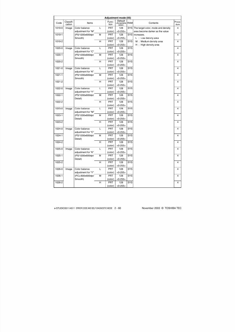
8/2/2019 ES-3511 Service Handbook
http://slidepdf.com/reader/full/es-3511-service-handbook 80/543
e-STUDIO3511/4511 ERROR CODE AND SELF-DIAGNOSTIC MODE 2 - 60 November 2003 © TOSHIBA TEC
128
<0-255>
128
<0-255>
128<0-255>
128
<0-255>
128
<0-255>
128
<0-255>
128
<0-255>
128
<0-255>
128
<0-255>
128
<0-255>
128
<0-255>
128
<0-255>
128
<0-255>
128
<0-255>
128
<0-255>
128
<0-255>
128
<0-255>
128
<0-255>
128
<0-255>
128
<0-255>
128
<0-255>128
<0-255>
128
<0-255>
128
<0-255>
SYS
SYS
SYS
SYS
SYS
SYS
SYS
SYS
SYS
SYS
SYS
SYS
SYS
SYS
SYS
SYS
SYS
SYS
SYS
SYS
SYS
SYS
SYS
SYS
Adjustment mode (05)
CodeClassifi-cation
ItemsFunc-tion
Default<Acceptable
value>RAM Contents
Proce-dure
1019-0
1019-1
1019-2
1020-0
1020-1
1020-2
1021-0
1021-1
1021-2
1022-0
1022-1
1022-2
1023-0
1023-1
1023-2
1024-0
1024-1
1024-2
1025-0
1025-1
1025-2
1026-0
1026-1
1026-2
Image
Image
Image
Image
Image
Image
Image
Image
Color balance
adjustment for “M”
(PS/1200x600dpi/
Smooth)
Color balance
adjustment for “C”
(PS/1200x600dpi/
Smooth)
Color balance
adjustment for “K”
(PS/1200x600dpi/
Smooth)
Color balance
adjustment for “Y”
(PS/1200x600dpi/
Detail)
Color balance
adjustment for “M”
(PS/1200x600dpi/
Detail)
Color balance
adjustment for “C”
(PS/1200x600dpi/
Detail)
Color balance
adjustment for “K”
(PS/1200x600dpi/
Detail)
Color balance
adjustment for “Y”
(PCL/600x600dpi/
Smooth)
L
M
H
L
M
H
L
M
H
L
M
H
L
M
H
L
M
H
L
M
H
L
M
H
PRT
(color)
PRT
(color)
PRT(color)
PRT
(color)
PRT
(color)
PRT
(color)
PRT
(color)
PRT
(color)
PRT
(color)
PRT
(color)
PRT
(color)
PRT
(color)
PRT
(color)
PRT
(color)
PRT
(color)
PRT
(color)
PRT
(color)
PRT
(color)
PRT
(color)
PRT
(color)
PRT
(color)PRT
(color)
PRT
(color)
PRT
(color)
The target color, mode and density
area become darker as the value
increases.
L : Low density area
M : Medium density areaH : High density area
4
4
4
4
4
4
4
4
4
4
4
4
4
4
4
4
4
4
4
4
4
4
4
4

8/2/2019 ES-3511 Service Handbook
http://slidepdf.com/reader/full/es-3511-service-handbook 81/543
November 2003 © TOSHIBA TEC 2 - 61 e-STUDIO3511/4511 ERROR CODE AND SELF-DIAGNOSTIC MODE
Adjustment mode (05)
CodeClassifi-cation
ItemsFunc-tion
Default<Acceptable
value>RAM Contents
Proce-dure
1027-0
1027-1
1027-2
1028-0
1028-1
1028-2
1029-0
1029-1
1029-2
1030-0
1030-1
1030-2
1031-0
1031-1
1031-2
1032-0
1032-1
1032-2
1033-0
1033-1
1033-2
1034-0
1034-1
1034-2
Image
Image
Image
Image
Image
Image
Image
Image
Color balance
adjustment for “M”
(PCL/600x600dpi/
Smooth)
Color balance
adjustment for “C”
(PCL/600x600dpi/
Smooth)
Color balance
adjustment for “K”
(PCL/600x600dpi/
Smooth)
Color balance
adjustment for “Y”
(PCL/600x600dpi/
Detail)
Color balance
adjustment for “M”
(PCL/600x600dpi/
Detail)
Color balance
adjustment for “C”
(PCL/600x600dpi/
Detail)
Color balance
adjustment for “K”
(PCL/600x600dpi/
Detail)
Color balance
adjustment for “Y”
(PCL/
1200x600dpi/
Smooth)
L
M
H
L
M
H
L
M
H
L
M
H
L
M
H
L
M
H
L
M
H
L
M
H
PRT
(color)
PRT
(color)
PRT(color)
PRT
(color)
PRT
(color)
PRT
(color)
PRT
(color)
PRT
(color)
PRT
(color)
PRT
(color)
PRT
(color)
PRT
(color)
PRT
(color)
PRT
(color)
PRT
(color)
PRT
(color)
PRT
(color)
PRT
(color)
PRT
(color)
PRT
(color)
PRT
(color)PRT
(color)
PRT
(color)
PRT
(color)
128
<0-255>
128
<0-255>
128<0-255>
128
<0-255>
128
<0-255>
128
<0-255>
128
<0-255>
128
<0-255>
128
<0-255>
128
<0-255>
128
<0-255>
128
<0-255>
128
<0-255>
128
<0-255>
128
<0-255>
128
<0-255>
128
<0-255>
128
<0-255>
128
<0-255>
128
<0-255>
128
<0-255>128
<0-255>
128
<0-255>
128
<0-255>
SYS
SYS
SYS
SYS
SYS
SYS
SYS
SYS
SYS
SYS
SYS
SYS
SYS
SYS
SYS
SYS
SYS
SYS
SYS
SYS
SYS
SYS
SYS
SYS
The target color, mode and density
area become darker as the value
increases.
L : Low density area
M : Medium density areaH : High density area
4
4
4
4
4
4
4
4
4
4
4
4
4
4
4
4
4
4
4
4
4
4
4
4

8/2/2019 ES-3511 Service Handbook
http://slidepdf.com/reader/full/es-3511-service-handbook 82/543
e-STUDIO3511/4511 ERROR CODE AND SELF-DIAGNOSTIC MODE 2 - 62 November 2003 © TOSHIBA TEC
128
<0-255>
128
<0-255>
128<0-255>
128
<0-255>
128
<0-255>
128
<0-255>
128
<0-255>
128
<0-255>
128
<0-255>
128
<0-255>
128
<0-255>
128
<0-255>
128
<0-255>
128
<0-255>
128
<0-255>
128
<0-255>
128
<0-255>
128
<0-255>
128
<0-255>
128
<0-255>
128
<0-255>255
<0-255>
255
<0-255>
255
<0-255>
255
<0-255>
Color balance
adjustment for “M”
(PCL/
1200x600dpi/
Smooth)
Color balance
adjustment for “C”
(PCL/
1200x600dpi/
Smooth)
Color balance
adjustment for “K”
(PCL/
1200x600dpi/
Smooth)
Color balance
adjustment for “Y”
(PCL/
1200x600dpi/
Detail)
Color balance
adjustment for “M”
(PCL/
1200x600dpi/
Detail)
Color balance
adjustment for “C”
(PCL/
1200x600dpi/
Detail)
Color balance
adjustment for “K”
(PCL/
1200x600dpi/
Detail)
Adjustment of
maximum toner
amount
(Plain paper)
Adjustment of
maximum toner
amount
(Thick paper 1)
L
M
H
L
M
H
L
M
H
L
M
H
L
M
H
L
M
H
L
M
H
PS
PCL
PS
PCL
PRT
(color)
PRT
(color)
PRT(color)
PRT
(color)
PRT
(color)
PRT
(color)
PRT
(color)
PRT
(color)
PRT
(color)
PRT
(color)
PRT
(color)
PRT
(color)
PRT
(color)
PRT
(color)
PRT
(color)
PRT
(color)
PRT
(color)
PRT
(color)
PRT
(color)
PRT
(color)
PRT
(color)PRT
(color)
PRT
(color)
PRT
(color)
PRT
(color)
1035-0
1035-1
1035-2
1036-0
1036-1
1036-2
1037-0
1037-1
1037-2
1038-0
1038-1
1038-2
1039-0
1039-1
1039-2
1040-0
1040-1
1040-2
1041-0
1041-1
1041-2
1046-0
1046-1
1047-0
1047-1
Image
Image
Image
Image
Image
Image
Image
Image
Image
Adjustment mode (05)
CodeClassifi-cation
ItemsFunc-tion
Default<Acceptable
value>RAM Contents
Proce-dure
SYS
SYS
SYS
SYS
SYS
SYS
SYS
SYS
SYS
SYS
SYS
SYS
SYS
SYS
SYS
SYS
SYS
SYS
SYS
SYS
SYS
SYS
SYS
SYS
SYS
The target color, mode and density
area become darker as the value
increases.
L : Low density area
M : Medium density areaH : High density area
When the value decreases, the
image becomes lighter.
Note:
When the value increases, the image
offsetting may occur.
4
4
4
4
4
4
4
4
4
4
4
4
4
4
4
4
4
4
4
4
4
4
4
4
4

8/2/2019 ES-3511 Service Handbook
http://slidepdf.com/reader/full/es-3511-service-handbook 83/543
November 2003 © TOSHIBA TEC 2 - 63 e-STUDIO3511/4511 ERROR CODE AND SELF-DIAGNOSTIC MODE
4
4
4
4
4
4
1
1
1
1
1
1
1
1
1
1
1
1
1
1
1
1
When the value decreases, the
image becomes lighter.
Note:
When the value increases, the image
offsetting may occur.
When the value decreases, the
printing density becomes lighter.
When the value increases by “1”, the
reproduction ratio of primary scanning
direction increases by approx. 0.1%.
Effective with the resolution other
than 600 dpi.
When the value increases, originals
tend to be judged as monochrome,
and when the value decreases, they
tend to be judged as color in auto-
color mode.
Adjusts the level of background. When
the value increases, the background
becomes more brightened.
Adjusts the black density of the
scanned image. When the value
increases, the black density becomes
darker.
Sets the color space format of the
output image.
0: sRGB 1: AppleRGB
2: ROMMRGB 3: AdobeRGB
SYS
SYS
SYS
SYS
SYS
SYS
SYS
SYS
SYS
SYS
SYS
SYS
SYS
SYS
SYS
SYS
SYS
SYS
SYS
SYS
SYS
SYS
PRT
(color)
PRT
(color)
PRT(color)
PRT
(color)
PRT
(color)
PRT
(color)
PRT
(color)
PRT
(color)
PRT
(color)
PRT
(color)
SCN
(color)
SCN
(color)
SCN
(color)
SCN
(color)
SCN
(color)
SCN
(color)
SCN
(color)
SCN
(color)
SCN(color)
SCN
(color)
SCN
(color)
SCN
(color)
255
<0-255>
255
<0-255>
255<0-255>
255
<0-255>
200
<0-255>
200
<0-255>
176
<0-255>
176
<0-255>
176
<0-255>
176
<0-255>
128
<0-255>
70
<0-255>
70
<0-255>
0
<0-50>
0
<0-50>
0
<0-50>
0
<0-4>
0
<0-4>
0<0-4>
0
<0-3>
0
<0-3>
0
<0-3>
Adjustment of
maximum toner
amount
(Thick paper 2)
Adjustment ofmaximum toner
amount
(Thick paper 3)
Adjustment of
maximum toner
amount
(OHP film)
Upper limit
in toner
saving mode
Reproduction ratio fine
adjustment of primary
scanning direction
Judgment threshold for ACS
Judgment threshold for ACS
on original set on the RADF
Fine adjustment
of background
Fine adjustment
of black density
RGB conversion
method selection
PS
PCL
PS
PCL
PS
PCL
Text
Printed
image
Photo
Text
Printed
image
Photo
Text
Printed
image
Photo
Image
Image
Image
Image
Image
Image
Image
Image
Image
Image
1048-0
1048-1
1049-0
1049-1
1050-0
1050-1
1055
1056
1057
1058
1060
1065
1066
1070
1071
1072
1075
1076
1077
1080
1081
1082
Adjustment mode (05)
CodeClassifi-cation
ItemsFunc-tion
Default<Acceptable
value>RAM Contents
Proce-dure

8/2/2019 ES-3511 Service Handbook
http://slidepdf.com/reader/full/es-3511-service-handbook 84/543
e-STUDIO3511/4511 ERROR CODE AND SELF-DIAGNOSTIC MODE 2 - 64 November 2003 © TOSHIBA TEC
When the value increases, the image
becomes sharper. When the value
decreases, the image becomes
softer.
The smaller the value is, the less themoire becomes.
* The default value 0 is equivalent to
16 (center value).
When the value increases, the image
becomes darker.
Sets the changing amount by 1 step
at the density adjustment.
When the value increases, the image
of the “dark” steps becomes darker.
Sets the changing amount by 1 step
at the density adjustment.
When the value increases, the image
of the “light” steps becomes lighter.
When the value increases, the image
becomes darker.
1
1
1
1
1
1
1
1
1
1
1
1
1
1
1
1
1
1
1
1
1
1
1
SYS
SYS
SYS
SYS
SYS
SYS
SYS
SYS
SYS
SYS
SYS
SYS
SYS
SYS
SYS
SYS
SYS
SYS
SYS
SYS
SYS
SYS
SYS
0
<0-31>
0
<0-31>
0
<0-31>
128
<0-255>
128
<0-255>
128
<0-255>
128
<0-255>
128
<0-255>
20
<0-255>
20
<0-255>
20
<0-255>
20
<0-255>
20
<0-255>
20
<0-255>
20
<0-255>
20
<0-255>
20
<0-255>
20
<0-255>
128
<0-255>
128<0-255>
128
<0-255>
128
<0-255>
128
<0-255>
Sharpness
adjustment
Density adjust-
ment “manual
density” fine
adjustment/Center
value
Density adjust-
ment “manual
density” fine
adjustment/Dark
step value
Density adjust-
ment “manual
density” fine
adjustment/Light
step value
Density adjust-
ment “automatic
density” fineadjustment
Text
Printed
image
Photo
Text
/Photo
Text
Printed
image
Photo
Map
Text
/Photo
Text
Printed
image
Photo
Map
Text
/Photo
Text
Printed
image
Photo
Map
Text
/Photo
Text
Printed
image
Photo
Map
SCN
(color)
SCN
(color)
SCN
(color)
PPC
(color)
PPC
(color)
PPC
(color)
PPC
(color)
PPC
(color)
PPC
(color)
PPC
(color)
PPC
(color)
PPC
(color)
PPC
(color)
PPC
(color)
PPC
(color)
PPC
(color)
PPC
(color)
PPC
(color)
PPC
(color)
PPC(color)
PPC
(color)
PPC
(color)
PPC
(color)
Adjustment mode (05)
CodeClassifi-cation
ItemsFunc-tion
Default<Acceptable
value>RAM Contents
Proce-dure
1086
1087
1088
1550
1551
1552
1553
1554
1560
1561
1562
1563
1564
1570
1571
1572
1573
1574
1580
1581
1582
1583
1584
Image
Image
Image
Image
Image

8/2/2019 ES-3511 Service Handbook
http://slidepdf.com/reader/full/es-3511-service-handbook 85/543
November 2003 © TOSHIBA TEC 2 - 65 e-STUDIO3511/4511 ERROR CODE AND SELF-DIAGNOSTIC MODE
Adjustment of
maximum toner
amount
Maximum text
density adjust-
ment
Automatic gamma
adjustment
Judgment threshold for ACS
Judgment threshold for ACS
on original set on the RADF
Automatic
offsetting adjust-
ment for back-
ground process-
ing (background
density)
Automatic
offsetting adjust-
ment for back-ground process-
ing (text density)
When the value decreases, the
image becomes lighter.
Note:
When the value increases, image
offsetting may occur.
When the value increases by “1”, the
maximum text density of each color
becomes darker.
Automatic adjustment of gradation
reproduction in the Full Color Mode
(each color of Y, M, C and K) and
Black Mode.
Automatic adjustment of gradation
reproduction in the Full Color Mode
(each color of Y, M, C and K).
When the value increases, originals
tend to be judged as black, and when
the value decreases, they tend to be
judged as color in auto-color mode.
When the value increases, the
background becomes darker.
When the value increases, the text
becomes darker.
1
1
1
1
1
1
1
1
1
7
7
1
1
1
1
1
1
1
1
1
1
1
1
255
<0-255>
249
<0-255>
237<0-255>
237
<0-255>
249
<0-255>
5
<0-10>
5
<0-10>
5
<0-10>
5
<0-10>
-
-
70
<0-255>
70
<0-255>
128
<0-255>
128
<0-255>
128
<0-255>
128
<0-255>
128
<0-255>
128
<0-255>
128<0-255>
128
<0-255>
128
<0-255>
128
<0-255>
SYS
SYS
SYS
SYS
SYS
SYS
SYS
SYS
SYS
SYS
SYS
SYS
SYS
SYS
SYS
SYS
SYS
SYS
SYS
SYS
SYS
SYS
SYS
Plain
paper
Thick
paper 1
Thickpaper 2
Thick
paper 3
OHP film
Y
M
C
K
Color/
Black
Color
Text
/Photo
Text
Printed
image
Photo
Map
Text
/Photo
Text
Printed
image
Photo
Map
PPC
(color)
PPC
(color)
PPC(color)
PPC
(color)
PPC
(color)
PPC
(color)
PPC
(color)
PPC
(color)
PPC
(color)
PPC
PPC
PPC
(color)
PPC
(color)
PPC
(color)
PPC
(color)
PPC
(color)
PPC
(color)
PPC
(color)
PPC
(color)
PPC(color)
PPC
(color)
PPC
(color)
PPC
(color)
Image
Image
Image
Image
Image
Image
Image
1612
1613
1614
1615
1616
1630
1631
1632
1633
1642
1643
1675
1676
1688
1689
1690
1691
1692
1693
1694
1695
1696
1697
Adjustment mode (05)
CodeClassifi-cation
ItemsFunc-tion
Default<Acceptable
value>RAM Contents
Proce-dure

8/2/2019 ES-3511 Service Handbook
http://slidepdf.com/reader/full/es-3511-service-handbook 86/543
e-STUDIO3511/4511 ERROR CODE AND SELF-DIAGNOSTIC MODE 2 - 66 November 2003 © TOSHIBA TEC
Manual offsetting
adjustment for
background
processing
(backgrounddensity)
Manual offsetting
adjustment for
background
processing (text
density)
Text/Photo reproduction
level adjustment
Sharpness
adjustment / Full
Color Mode
Sharpness adjustment /Auto
Color Mode (Text/Photo)
1698
1699
1700
1701
1702
1708
1709
1710
1711
1712
1725
1737
1738
1739
1740
1741
1757
Image
Image
Image
Image
Image
128
<0-255>
128
<0-255>
128<0-255>
128
<0-255>
128
<0-255>
128
<0-255>
128
<0-255>
128
<0-255>
128
<0-255>
128
<0-255>
0
<0-5>
0
<0-31>
0
<0-31>
0
<0-31>
0
<0-31>0
<0-31>
EUR: 0
UC: 0
JAPN: 22
<0-31>
SYS
SYS
SYS
SYS
SYS
SYS
SYS
SYS
SYS
SYS
SYS
SYS
SYS
SYS
SYS
SYS
SYS
When the value increases, the
background becomes darker.
When the value increases, the text
becomes darker.
0: Default
1: Photo oriented 2 (The printed image
reproduction level higher than that
of the Photo oriented 1)
2: Photo oriented 1 (The printed image
reproduction level higher than that
of the Default)
3: Equivalent to the Default
4: Text oriented 1 (The text reproduc-
tion level higher than that of the De-
fault)
5: Text oriented 2 (The text reproduc-
tion level higher than that of the Text
oriented 1)
When the value increases, the image
becomes sharper. When the value de-
creases, the image becomes softer.
The smaller the value is, the less the
moire becomes.
*The default value 0 is equivalent to
16 (center value).
When the value increases, the image
becomes sharper. When the value
decreases, the image becomes
softer. The smaller the value is, the
less the moire becomes.
* The default value 0 is equivalent to
16(center value).
Text
/Photo
Text
Printedimage
Photo
Map
Text
/Photo
Text
Printed
image
Photo
Map
Text
/Photo
Text
Printed
image
Photo
Map
PPC
(color)
PPC
(color)
PPC(color)
PPC
(color)
PPC
(color)
PPC
(color)
PPC
(color)
PPC
(color)
PPC
(color)
PPC
(color)
PPC
(color)
PPC
(color)
PPC
(color)
PPC
(color)
PPC
(color)PPC
(color)
PPC
(color)
1
1
1
1
1
1
1
1
1
1
1
1
1
1
1
1
1
Adjustment mode (05)
CodeClassifi-cation
ItemsFunc-tion
Default<Acceptable
value>RAM Contents
Proce-dure
04/10
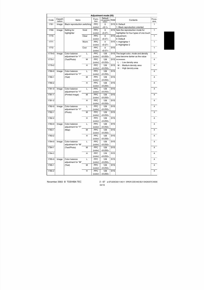
8/2/2019 ES-3511 Service Handbook
http://slidepdf.com/reader/full/es-3511-service-handbook 87/543
November 2003 © TOSHIBA TEC 2 - 67 e-STUDIO3511/4511 ERROR CODE AND SELF-DIAGNOSTIC MODE
0: Default
1: Black reproduction oriented
Sets the reproduction mode for
highlighter for four types of one touch
adjustment.0: Default
1: Highlighter 1
2: Highlighter 2
The target color, mode and density
area become darker as the value
increases.
L : Low density area
M : Medium density area
H : High density area
1
1
1
1
1
4
4
4
4
4
4
4
4
4
4
4
4
4
4
4
4
4
4
4
4
4
SYS
SYS
SYS
SYS
SYS
SYS
SYS
SYS
SYS
SYS
SYS
SYS
SYS
SYS
SYS
SYS
SYS
SYS
SYS
SYS
SYS
SYS
SYS
SYS
SYS
SYS
1761
1769
1770
1771
1772
1779-0
1779-1
1779-2
1780-0
1780-1
1780-2
1781-0
1781-1
1781-2
1782-0
1782-1
1782-2
1783-0
1783-1
1783-2
1784-0
1784-1
1784-2
1785-0
1785-1
1785-2
Image
Image
Image
Image
Image
Image
Image
Image
Image
Black reproduction switching
Setting for
highlighter
Color balance
adjustment for “Y”
(Text/Photo)
Color balance
adjustment for “Y”
(Text)
Color balance
adjustment for “Y”
(Printed image)
Color balance
adjustment for “Y”(Photo)
Color balance
adjustment for “Y”
(Map)
Color balance
adjustment for “M”(Text/Photo)
Color balance
adjustment for “M”
(Text)
Vivid
Clear
Warm
Cool
L
M
H
L
M
H
L
M
H
L
M
H
L
M
H
L
M
H
L
M
H
PPC
(color)
PPC
(color)
PPC(color)
PPC
(color)
PPC
(color)
PPC
(color)
PPC
(color)
PPC
(color)
PPC
(color)
PPC
(color)
PPC
(color)
PPC
(color)
PPC
(color)
PPC
(color)
PPC
(color)PPC
(color)
PPC
(color)
PPC
(color)
PPC
(color)
PPC
(color)
PPC
(color)PPC
(color)
PPC
(color)
PPC
(color)
PPC
(color)
PPC
(color)
0
<0-1>
0
<0-27>
0<0-27>
0
<0-27>
0
<0-27>
128
<0-255>
128
<0-255>
128
<0-255>
128
<0-255>
128
<0-255>
128
<0-255>
128
<0-255>
128
<0-255>
128
<0-255>
128
<0-255>128
<0-255>
128
<0-255>
128
<0-255>
128
<0-255>
128
<0-255>
128
<0-255>128
<0-255>
128
<0-255>
128
<0-255>
128
<0-255>
128
<0-255>
Adjustment mode (05)
CodeClassifi-cation
ItemsFunc-tion
Default<Acceptable
value>RAM Contents
Proce-dure
04/10
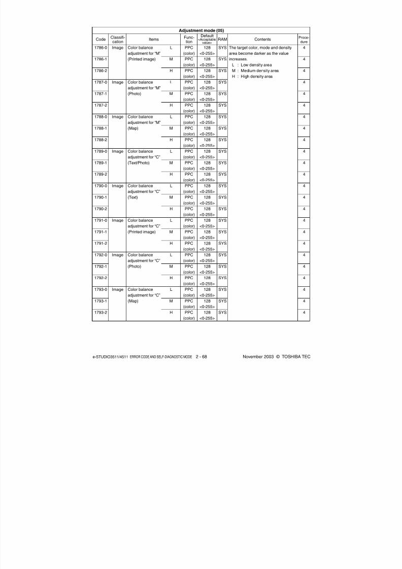
8/2/2019 ES-3511 Service Handbook
http://slidepdf.com/reader/full/es-3511-service-handbook 88/543
e-STUDIO3511/4511 ERROR CODE AND SELF-DIAGNOSTIC MODE 2 - 68 November 2003 © TOSHIBA TEC
SYS
SYS
SYS
SYS
SYS
SYS
SYS
SYS
SYS
SYS
SYS
SYS
SYS
SYS
SYS
SYS
SYS
SYS
SYS
SYS
SYS
SYS
SYS
SYS
The target color, mode and density
area become darker as the value
increases.
L : Low density area
M : Medium density areaH : High density area
Adjustment mode (05)
CodeClassifi-cation
ItemsFunc-tion
Default<Acceptable
value>RAM Contents
Proce-dure
1786-0
1786-1
1786-2
1787-0
1787-1
1787-2
1788-0
1788-1
1788-2
1789-0
1789-1
1789-2
1790-0
1790-1
1790-2
1791-0
1791-1
1791-2
1792-0
1792-1
1792-2
1793-0
1793-1
1793-2
Image
Image
Image
Image
Image
Image
Image
Image
Color balance
adjustment for “M”
(Printed image)
Color balance
adjustment for “M”
(Photo)
Color balance
adjustment for “M”
(Map)
Color balance
adjustment for “C”
(Text/Photo)
Color balance
adjustment for “C”
(Text)
Color balance
adjustment for “C”
(Printed image)
Color balance
adjustment for “C”
(Photo)
Color balance
adjustment for “C”
(Map)
L
M
H
L
M
H
L
M
H
L
M
H
L
M
H
L
M
H
L
M
H
L
M
H
PPC
(color)
PPC
(color)
PPC(color)
PPC
(color)
PPC
(color)
PPC
(color)
PPC
(color)
PPC
(color)
PPC
(color)
PPC
(color)
PPC
(color)
PPC
(color)
PPC
(color)
PPC
(color)
PPC
(color)
PPC
(color)
PPC
(color)
PPC
(color)
PPC
(color)
PPC
(color)
PPC
(color)PPC
(color)
PPC
(color)
PPC
(color)
128
<0-255>
128
<0-255>
128<0-255>
128
<0-255>
128
<0-255>
128
<0-255>
128
<0-255>
128
<0-255>
128
<0-255>
128
<0-255>
128
<0-255>
128
<0-255>
128
<0-255>
128
<0-255>
128
<0-255>
128
<0-255>
128
<0-255>
128
<0-255>
128
<0-255>
128
<0-255>
128
<0-255>128
<0-255>
128
<0-255>
128
<0-255>
4
4
4
4
4
4
4
4
4
4
4
4
4
4
4
4
4
4
4
4
4
4
4
4

8/2/2019 ES-3511 Service Handbook
http://slidepdf.com/reader/full/es-3511-service-handbook 89/543
November 2003 © TOSHIBA TEC 2 - 69 e-STUDIO3511/4511 ERROR CODE AND SELF-DIAGNOSTIC MODE
Color balance
adjustment for “K”
(Text/Photo)
Color balance
adjustment for “K”
(Text)
Color balance
adjustment for “K”
(Printed image)
Color balance
adjustment for “K”
(Photo)
Color balance
adjustment for “K”
(Map)
Upper limit value
of contrast voltage
Lower limit value
of contrast voltage
The target color, mode and density
area become darker as the value
increases.
L : Low density area
M : Medium density areaH : High density area
Sets the upper limit value of the
contrast voltage at the image quality
control. (Unit: V)
Sets the lower limit value of the
contrast voltage at the image quality
control. (Unit: V)
4
4
4
4
4
4
4
4
4
4
4
4
4
4
4
4
4
4
4
4
4
4
4
SYS
SYS
SYS
SYS
SYS
SYS
SYS
SYS
SYS
SYS
SYS
SYS
SYS
SYS
SYS
M
M
M
M
M
M
M
M
PPC
(color)
PPC
(color)
PPC(color)
PPC
(color)
PPC
(color)
PPC
(color)
PPC
(color)
PPC
(color)
PPC
(color)
PPC
(color)
PPC
(color)
PPC
(color)
PPC
(color)
PPC
(color)
PPC
(color)ALL
ALL
ALL
ALL
ALL
ALL
ALL
ALL
L
M
H
L
M
H
L
M
H
L
M
H
L
M
H
Y
M
C
K
Y
M
C
K
1794-0
1794-1
1794-2
1795-0
1795-1
1795-2
1796-0
1796-1
1796-2
1797-0
1797-1
1797-2
1798-0
1798-1
1798-2
1800-0
1800-1
1800-2
1800-3
1801-0
1801-1
1801-2
1801-3
Image
Image
Image
Image
Image
Image
control
Image
control
128
<0-255>
128
<0-255>
128<0-255>
128
<0-255>
128
<0-255>
128
<0-255>
128
<0-255>
128
<0-255>
128
<0-255>
128
<0-255>
128
<0-255>
128
<0-255>
128
<0-255>
128
<0-255>
128
<0-255>650
<0-999>
650
<0-999>
650
<0-999>
600
<0-999>
120
<0-999>
120
<0-999>120
<0-999>
120
<0-999>
Adjustment mode (05)
CodeClassifi-cation
ItemsFunc-tion
Default<Acceptable
value>RAM Contents
Proce-dure
04/09

8/2/2019 ES-3511 Service Handbook
http://slidepdf.com/reader/full/es-3511-service-handbook 90/543
e-STUDIO3511/4511 ERROR CODE AND SELF-DIAGNOSTIC MODE 2 - 70 November 2003 © TOSHIBA TEC
M
M
M
M
M
M
M
M
M
M
M
M
M
M
M
M
M
M
M
M
M
M
M
M
Adjustment mode (05)
CodeClassifi-cation
ItemsFunc-tion
Default<Acceptable
value>RAM Contents
Proce-dure
1802-0
1802-1
1802-2
1802-3
1803-0
1803-1
1803-2
1803-3
1804-0
1804-1
1804-2
1804-3
1805-0
1805-1
1805-2
1805-3
1806-0
1806-1
1806-2
1806-3
1807-0
1807-1
1807-2
1807-3
Image
control
Image
control
Image
control
Image
control
Image
control
Image
control
Upper limit value
of laser power
Lower limit value
of laser power
Background
voltage actual
value display
Drum surface
potential charac-
teristic/slope
factor display
Drum surface
potential charac-
teristic/offset
factor display
Drum exposure
voltage character-istic/slope factor
display (main
charger grid low
voltage area)
Y
M
C
K
Y
M
C
K
Y
M
C
K
Y
M
C
K
Y
M
C
K
Y
M
C
K
ALL
ALL
ALL
ALL
ALL
ALL
ALL
ALL
ALL
ALL
ALL
ALL
ALL
ALL
ALL
ALL
ALL
ALL
ALL
ALL
ALL
ALL
ALL
ALL
800
<0-999>
800
<0-999>
800<0-999>
800
<0-999>
350
<0-999>
350
<0-999>
350
<0-999>
350
<0-999>
125
<0-999>
125
<0-999>
125
<0-999>
125
<0-999>
979
<0-999>
979
<0-999>
979
<0-999>990
<0-999>
-6
<-999-999>
-6
<-999-999>
-6
<-999-999>
-4
<-999-999>
58
<0-999>58
<0-999>
58
<0-999>
60
<0-999>
Sets the upper limit value of the laser
power at the image quality control.
(Unit: µW)
Sets the lower limit value of the laser
power at the image quality control.
(Unit: µW)
Displays the background voltage
when printing is operated. (Unit: V)
Displays the slope factor of the
approximate expression of the drum
surface potential to the main charger
grid voltage at the open-loop control.
Displays the offset factor of the
approximate expression of the drum
surface potential to the main charger
grid voltage at the open-loop control.
Displays the slope factor of the
approximate expression of the drumexposure voltage to the main charger
grid voltage at the open-loop control.
4
4
4
4
4
4
4
4
10
10
10
10
10
10
10
10
10
10
10
10
10
10
10
10

8/2/2019 ES-3511 Service Handbook
http://slidepdf.com/reader/full/es-3511-service-handbook 91/543
November 2003 © TOSHIBA TEC 2 - 71 e-STUDIO3511/4511 ERROR CODE AND SELF-DIAGNOSTIC MODE
Drum exposure
voltage character-
istic/offset factor
display (main
charger grid lowvoltage area)
Drum exposure
voltage character-
istic/slope factor
display (main
charger grid high
voltage area)
Drum exposure
voltage character-
istic/offset factor
display (main
charger grid high
voltage area)
Contrast voltage/
upper limit actual
value display
Contrast voltage/
lower limit actual
value display
Display of
backgroundvoltage/upper limit
actual value
1808-0
1808-1
1808-2
1808-3
1809-0
1809-1
1809-2
1809-3
1810-0
1810-1
1810-2
1810-3
1811-0
1811-1
1811-2
1811-3
1812-0
1812-1
1812-2
1812-3
1813-0
1813-1
1813-2
1813-3
Image
control
Image
control
Image
control
Image
control
Image
control
Image
control
ALL
ALL
ALL
ALL
ALL
ALL
ALL
ALL
ALL
ALL
ALL
ALL
ALL
ALL
ALL
ALL
ALL
ALL
ALL
ALL
ALL
ALL
ALL
ALL
Displays the offset factor of the
approximate expression of the drum
exposure voltage to the main charger
grid voltage at the open-loop control.
Displays the slope factor of the
approximate expression of the drum
exposure voltage to the main charger
grid voltage at the open-loop control.
Displays the offset factor of the
approximate expression of the drum
exposure voltage to the main charger
grid voltage at the open-loop control.
Displays the upper limit value of the
contrast voltage when printing is
operated. (Unit: V)
Displays the lower limit value of the
contrast voltage when printing is
operated. (Unit: V)
Displays the upper limit value of the
background voltage when printing isoperated. (Unit: V)
35
<-999-999>
35
<-999-999>
35<-999-999>
42
<-999-999>
49
<0-999>
49
<0-999>
49
<0-999>
53
<0-999>
41
<-999-999>
41
<-999-999>
41
<-999-999>
47
<-999-999>
500
<0-999>
500
<0-999>
500
<0-999>
600
<0-999>
120
<0-999>
120
<0-999>
120
<0-999>
120
<0-999>
170
<0-999>170
<0-999>
170
<0-999>
170
<0-999>
M
M
M
M
M
M
M
M
M
M
M
M
M
M
M
M
M
M
M
M
M
M
M
M
10
10
10
10
10
10
10
10
10
10
10
10
10
10
10
10
10
10
10
10
10
10
10
10
Adjustment mode (05)
CodeClassifi-cation
ItemsFunc-tion
Default<Acceptable
value>RAM Contents
Proce-dure
Y
M
C
K
Y
M
C
K
Y
M
C
K
Y
M
C
K
Y
M
C
K
Y
M
C
K

8/2/2019 ES-3511 Service Handbook
http://slidepdf.com/reader/full/es-3511-service-handbook 92/543
e-STUDIO3511/4511 ERROR CODE AND SELF-DIAGNOSTIC MODE 2 - 72 November 2003 © TOSHIBA TEC
Displays the lower limit value of the
background voltage when printing is
operated. (Unit: V)
Displays the actual number of time
the contrast voltage has been
corrected at the closed-loop control.
Displays the actual number of time
the laser power has been corrected
at the closed-loop control.
Displays the laser power value when
copying in the Black Mode.
(Bit value)
Perform the correction of the setting
05-1817. (Unit: %)
Displays the laser power value when
printing in the Black Mode.
(Bit value)
Perform the correction of the setting
05-1820. (Unit: %)
Corrects the 2nd transfer roller bias
output of the trailing edge of paper
(05-227, 229, 230, 231 and 232).
Correction factor: %
10
10
10
10
10
10
10
10
10
10
10
10
2
1
2
1
14
14
14
14
14
Background
voltage/lower limit
actual value
display
Contrast voltage/
correction number
of time display
Laser power
correction/number
of time display
Laser power actual value
display
Laser power correcting
factor
Laser power actual value
display
Laser power correcting
factor
2nd transfer roller
bias correction of
trailing edge of
paper
ALL
ALL
ALL
ALL
ALL
ALL
ALL
ALL
ALL
ALL
ALL
ALL
PPC
(black)
PPC
(black)
PRT
(black)
PRT
(black)
ALL
ALL
ALL
ALL
ALL
1814-0
1814-1
1814-2
1814-3
1815-0
1815-1
1815-2
1815-3
1816-0
1816-1
1816-2
1816-3
1817
1819
1820
1821
1822-0
1822-1
1822-2
1822-3
1822-4
Image
control
Image
control
Image
control
Image
control
Image
control
Image
control
Image
control
Transfer
Adjustment mode (05)
CodeClassifi-cation
ItemsFunc-tion
Default<Acceptable
value>RAM Contents
Proce-dure
Y
M
C
K
Y
M
C
K
Y
M
C
K
Plain
paper
Thick
paper 1
Thick
paper 2
Thick
paper 3OHP film
80
<0-999>
80
<0-999>
80<0-999>
80
<0-999>
0
<0-255>
0
<0-255>
0
<0-255>
0
<0-255>
0
<0-255>
0
<0-255>
0
<0-255>
0
<0-255>
92
<0-255>
100
<100-255>
92
<0-255>
100
<100-255>
100
<0-255>
88
<0-255>
90
<0-255>
90
<0-255>90
<0-255>
M
M
M
M
M
M
M
M
M
M
M
M
M
M
M
M
M
M
M
M
M
04/05

8/2/2019 ES-3511 Service Handbook
http://slidepdf.com/reader/full/es-3511-service-handbook 93/543
November 2003 © TOSHIBA TEC 2 - 73 e-STUDIO3511/4511 ERROR CODE AND SELF-DIAGNOSTIC MODE
10
10
10
10
10
10
10
10
10
10
10
10
10
10
14
14
14
2
2
2
145
<0-255>
120
<0-255>
139
<0-255>
118
<0-255>
138
<0-255>
112
<0-255>
123
<0-255>
112
<0-255>
145
<0-255>
139
<0-255>
145
<0-255>
139
<0-255>
118
<0-255>112
<0-255>
40
<0-100>
60
<0-100>
40
<0-100>
190
<0-255>
180
<0-255>
200
<0-255>
1823-0
1823-1
1823-2
1823-3
1825-0
1825-1
1825-2
1825-3
1826-0
1826-1
1827-0
1827-1
1828-0
1828-1
1829-0
1829-1
1829-2
1831
1832
1833
Transfer
Transfer
Transfer
Transfer
Transfer
Transfer
Transfer
Transfer
Transfer
Display of
intermediate level
of 2nd transfer
roller bias actual
value of trailingedge of paper
(Plain paper)
Display of
intermediate level
of 2nd transfer
roller bias actual
value of trailing
edge of paper
(Thick paper 1)
Display of intermediate level
of 2nd transfer roller bias
actual value of trailing edge
of paper (Thick paper 2)
Display of intermediate level
of 2nd transfer roller bias
actual value of trailing edge
of paper (Thick paper 3)
Display of intermediate level
of 2nd transfer roller biasactual value of trailing edge
of paper (OHP film)
1st transfer roller
bias correction at
deceleration
1st transfer roller bias actual
value display at deceleration
(Thick paper 2)
1st transfer roller bias actual
value display at deceleration(Thick paper 3)
1st transfer roller bias actual
value display at deceleration
(OHP film)
ALL
(black)
ALL
(black)
ALL
(color)
ALL
(color)
ALL
(black)
ALL
(black)
ALL
(color)
ALL
(color)
ALL
(black)
ALL
(color)
ALL
(black)
ALL
(color)
ALL
(black)ALL
(color)
ALL
ALL
ALL
ALL
(black)
ALL
(black)
ALL
(black)
Displays the value of 2nd transfer
roller bias when the actual printing is
operated.
(The value corrected in 05-1822 is
displayed.)
Displays the value of 2nd transfer
roller bias when the actual printing is
operated.
(The value corrected in 05-1822 is
displayed.)
Corrects the 1st transfer roller bias
output.
Correction factor: %
Displays the value of 1st transfer
roller bias at deceleration when the
actual printing is operated.
(The value corrected in 05-1829 is
displayed.)
Adjustment mode (05)
CodeClassifi-cation
ItemsFunc-tion
Default<Acceptable
value>RAM Contents
Proce-dure
M
M
M
M
M
M
M
M
M
M
M
M
M
M
M
M
M
M
M
M
Single
side
Reverse
side at
duplexingSingle
side
Reverse
side at
duplexing
Single
side
Reverse
side at
duplexing
Single
side
Reverse
side at
duplexing
Thick
paper 2
Thick
paper 3
OHP
film
04/05

8/2/2019 ES-3511 Service Handbook
http://slidepdf.com/reader/full/es-3511-service-handbook 94/543
e-STUDIO3511/4511 ERROR CODE AND SELF-DIAGNOSTIC MODE 2 - 74 November 2003 © TOSHIBA TEC
Adjusts the output value of the 1st
transfer roller bias when the transfers
of all colors (Y, M, C and K) have
finished. When the value decreases,
the 1st transfer roller bias outputincreases.
This adjustment is valid only when
the value of the code 08-497 is “1”
(6 pages/minute).
Sets the offset amount of the 1st
transfer roller bias when the transfers
of all colors (Y, M, C and K) have
finished.
This adjustment is valid only when
the value of the code 08-497 is “1”
(6 pages/minute).
0: -500 V 1: -400 V 2: -300 V
3: -200 V 4: -100 V 5: 0 V
6: +100 V 7: +200 V 8: +300 V
9: +400 V 10: +500 V
Displays the actual value of the 1st
transfer roller bias when the transfers
of all colors (Y, M, C and K) have
finished.
This adjustment is valid only when the
value of the code 08-497 is “1”
(6 pages/minute).
As the value decreases, the 1st
transfer roller bias output increases
correspondingly.
The adjustment value becomes
effective when the Setting Mode (08-
541, 549 and 551) is 0 (invalid).
As the value decreases, the 1st
transfer roller bias output increases
correspondingly.
The adjustment value becomes
effective when the Setting Mode (08-
541, 549 and 551) is 0 (invalid).
Corrects the 2nd transfer roller biasoutput of leading/trailing edge of
paper (05-1840).
(Correcting factor: %)
M
M
M
M
M
M
M
M
M
M
1
1
2
3
14
14
14
14
14
14
1834
1835
1836
1837
1838-0
1838-1
1838-2
1838-3
1839-0
1839-1
Transfer
Transfer
Transfer
Transfer
Transfer
Transfer
1st transfer roller bias output
adjustment in low-speed
color printing
(Plain paper / Thick paper 1)
1st transfer roller bias
offsetting in low-speed color
printing
(Plain paper / Thick paper 1)
1st transfer roller bias actual
value display in low-speed
color printing
(Plain paper / Thick paper 1)
1st transfer roller bias output
adjustment
(Tab paper)
1st transfer roller
bias output
adjustment
(Tab paper)
2nd transfer rollerbias correction of
leading/trailing
edge of paper
(Tab paper)
175
<0-255>
5
<0-10>
175
<0-255>
135
<0-225>
135
<0-225>
140
<0-225>
145
<0-225>
150
<0-225>
100<0-100>
90
<0-100>
ALL
(color)
ALL
(color)
ALL
(color)
ALL
(black)
ALL
(color)
ALL
(color)
ALL
(color)
ALL
(color)
ALL
ALL
Y
M
C
K
Intermedi-ate level
bias of
trailing
edge
Bias of
leading/
trailing
edge
Adjustment mode (05)
CodeClassifi-cation
ItemsFunc-tion
Default<Acceptable
value>RAM Contents
Proce-dure
04/10

8/2/2019 ES-3511 Service Handbook
http://slidepdf.com/reader/full/es-3511-service-handbook 95/543
November 2003 © TOSHIBA TEC 2 - 75 e-STUDIO3511/4511 ERROR CODE AND SELF-DIAGNOSTIC MODE
As the value decreases, the 2nd
transfer roller bias output increases
correspondingly.
The adjustment value becomes
effective when the Setting Mode (08-544, 549 and 551) is 0 (invalid).
Sets the offset amount of 2nd transfer
roller bias.
0: -500V 1: -400V 2: -300V
3: -200V 4: -100V 5: 0V
6: +100V 7: +200V 8: +300V
9: +400V 10: +500V
Displays the value of 2nd transfer
roller bias on the leading/trailing edge
of paper when printing is performed.
(The value corrected in 05-1839 is
displayed.)
Displays the value of 1st transfer
roller bias when printing is operated.
Displays the value of 1st transfer
roller bias when printing is operated.
Displays the value of 2nd transferroller bias when printing is operated.
14
14
4
4
10
10
10
10
2
10
10
10
10
10
10
143
<0-158>
137
<0-158>
5
<0-10>
5
<0-10>
143
<0-225>
145
<0-225>
137
<0-225>
140
<0-225>
135
<0-225>
135
<0-225>
140
<0-225>
145
<0-225>
150
<0-225>
143<0-158>
137
<0-158>
M
M
M
M
M
M
M
M
M
M
M
M
M
M
M
1840-0
1840-1
1841-0
1841-1
1842-0
1842-1
1842-2
1842-3
1843
1844-0
1844-1
1844-2
1844-3
1845-0
1845-1
Transfer
Transfer
Transfer
Transfer
Transfer
Transfer
2nd transfer roller bias
output adjustment
(Tab paper)
2nd transfer roller bias
offsetting adjustment
(Tab paper)
Actual value
display of 2nd
transfer roller bias
of leading/trailing
edge of paper
(Tab paper)
1st transfer roller bias actual
value display
(Tab paper)
1st transfer roller
bias actual value
display
(Tab paper)
2nd transfer roller biasactual value display
(Tab paper)
Adjustment mode (05)
CodeClassifi-cation
ItemsFunc-tion
Default<Acceptable
value>RAM Contents
Proce-dure
04/10
Interme-
diate
level bias
of trailing
edge
Bias of
leading/
trailing
edge
Interme-
diate
level bias
of trailing
edge
Bias of
leading/
trailing
edge
Y
M
C
K
ALL
(black)
ALL
(color)
ALL
(black)
ALL
(color)
ALL
(black)
ALL
(black)
ALL
(color)
ALL
(color)
ALL
(black)
ALL
(color)
ALL
(color)
ALL
(color)
ALL
(color)
ALL(black)
ALL
(color)

8/2/2019 ES-3511 Service Handbook
http://slidepdf.com/reader/full/es-3511-service-handbook 96/543
e-STUDIO3511/4511 ERROR CODE AND SELF-DIAGNOSTIC MODE 2 - 76 November 2003 © TOSHIBA TEC
2.2.5 Setting mode (08)
The items in the setting code list can be set or changed in this setting mode (08).
[0][8]
[POWER]
[POWER] OFF/ON
(Exit)
[Digital key]
(Code)[START]
[CANCEL]
[Digital key]
*[FUNCTION CLEAR]
[ENTER]
or
[INTERRUPT]
( )Sets or
changes value(Stores value in RAM)
*Press [FUNCTION CLEAR] to enter minus (-).
[CLEAR]
(Corrects value)
Procedure 1
Procedure 2
Procedure 4
Procedure 5
[0][8]
[POWER]
[POWER]OFF/ON
(Exit)
[Digital key]
(Code)[START]
[ENTER]or
[INTERRUPT]
Adjustment valuecannot be changed( )
[0][8][POWER]
[POWER]OFF/ON
(Exit)
[Digital key](Code)
[Digital key](Sub-code)
[Digital key]
* [FUNCTION CLEAR]
Sets orchanges value
* Press [FUNCTION CLEAR] to enter minus (-).
[START] [START]
[CANCEL]
[START][ENTER]
or
[INTERRUPT](Stores value
in RAM)
[CLEAR](Corrects value)
[CLEAR](Corrects value)
[0][8]
[POWER]
[POWER] OFF/ON
(Exit)
[Digital key]
(Code)
[Digital key]
*[HELP][START]
[CANCEL][ENTER]
or
[INTERRUPT]
[CLEAR]
(Corrects value)
(Stores value in RAM)Sets or
changes value( )
*Press [HELP] to enter - .
Procedure 3
[0][8]
[POWER]
[POWER] OFF/ON
(Exit)[Digital key]
(Code)[START]
[CANCEL] or [CLEAR]
(Automatic setting)
[ENTER]
or
[INTERRUPT](Stores value in RAM)
04/05

8/2/2019 ES-3511 Service Handbook
http://slidepdf.com/reader/full/es-3511-service-handbook 97/543
November 2003 © TOSHIBA TEC 2 - 77 e-STUDIO3511/4511 ERROR CODE AND SELF-DIAGNOSTIC MODE
Procedure 9
Procedure 10
Procedure 11 and 12
[0][8]
[POWER]
[POWER] OFF/ON
(Exit)
[Digital key]
(Code)[Select button][START]
[CANCEL][ENTER]
or
[INTERRUPT]
[CLEAR]
(Corrects value)
(Stores value in RAM)
[0][8][POWER]
[POWER]OFF/ON
(Exit)
[Digital key](Code)
[Digital key](1st setting)
[Digital key](2nd setting)
[START] [START]
[CANCEL][ENTER]
or[INTERRUPT]
[CLEAR](Corrects value)
[CLEAR](Corrects value)
(Stores value in RAM)
[0][8][POWER]
[POWER] OFF/ON(Exit)
[Digital key](Code)
[Digital key]or
[Software keyboard][START]
[CANCEL]
[CLEAR](Corrects value)
*2(Stores value in RAM)*1 [MONITOR/PAUSE]
Sets orchanges value( )
[ENTER]
*1. Press [MONITOR/PAUSE] to enter "-", whenentering telephone number.
*2. The data are stored in SYS-RAM in procedure11 and stored in NIC-RAM in procedure 12.
Procedure 7
[0][8][POWER] [POWER] OFF/ON
(Exit)
[Digital key](Code)
[Digital key](Setting)
[CLEAR](Corrects value)
[START] (HDD formatting)
[CANCEL]
[ENTER]or
[INTERRUPT](Stores value in RAM)
Procedure 14
[0][8][POWER]
[POWER]OFF/ON
(Exit)
[Digital key](Code)
[Digital key](Sub-code)
[CLEAR](Corrects value)
[START] [START]
[CANCEL]
[ENTER]or
[INTERRUPT]
Adjustment valuecannot be changed

8/2/2019 ES-3511 Service Handbook
http://slidepdf.com/reader/full/es-3511-service-handbook 98/543
e-STUDIO3511/4511 ERROR CODE AND SELF-DIAGNOSTIC MODE 2 - 78 November 2003 © TOSHIBA TEC
200
201
202
203
204
205
206
5
1
1
1
1
1
1
General
General
User
interface
General
User
interface
User
interface
User
interface
Date and time setting
Destination selection
Counter installed externally
Line adjustment mode
Auto-clear timer setting
Auto power save mode timer
setting
Auto Shut Off Mode timer
setting (Sleep Mode)
ALL
ALL
ALL
ALL
ALL
ALL
ALL
-
<13 digits>
EUR: 0
UC: 1
JPN: 2
<0-3>
0
<0-4>
0
<0-1>
3
<0-10>
11
<0, 6-15>
Refer to
content
<0-20>
-
M
M
M
SYS
SYS
SYS
Year/month/date/day/hour/minute/
second
Example: 03 07 0 13 13 27 48
“Day” - “0” is for “Sunday”. Proceeds Mon-
day through Saturday from “1” to “6”.
0: EUR 1: UC
2: JPN 3: Other
0: No external counter
1: Coin controller2: Copy key card
3: Key copy counter
4: Key card for OEM1
0: For factory shipment 1: For line
*Field: “0” must be selected
Timer to return the equipment to the
default settings when the [START]
button is not pressed after the
function and the mode are set
0: Not cleared
1 to 10: Set number x 15 sec.
Timer to automatically switch to the
energy saving mode when the
equipment has not been used
0: Invalid 6: 3min. 7: 4min.
8: 5min. 9: 7min. 10: 10min.
11: 15min. 12: 20min. 13: 30min.
14: 45min. 15: 60min.
Timer to enter the Sleep Mode
automatically when the equipment
has not been used
0: 3min. 1: 5min. 2: 10min.
3: 15min. 4: 20min. 5: 25min.
6: 30min. 7: 40min. 8: 50min.
9: 60min. 10: 70min. 11: 80min.12: 90min. 13: 100min. 14: 110min.
15: 120min. 16: 150min. 17: 180min.
18: 210min. 19: 240min.
20: Not used
<Default value>
e-STUDIO3511: 9
e-STUDIO4511: 12
Setting mode (08)
Code Classifi-cation
ItemsFunc-tion
Default<Acceptable
value>RAM Contents
Proce-dure
Notes:
1. The digit after the hyphen in “Code” of the following table is a sub code.
2. In “RAM”, the NVRAM of the board in which the data of each code is stored is indicated. “M” stands for
the LGC board, “SYS” and “UTY” stands for the SYS board and “NIC” stands for the NIC board.
04/09

8/2/2019 ES-3511 Service Handbook
http://slidepdf.com/reader/full/es-3511-service-handbook 99/543
November 2003 © TOSHIBA TEC 2 - 79 e-STUDIO3511/4511 ERROR CODE AND SELF-DIAGNOSTIC MODE
0
<0-1>
0
<0-1>
148/105
<148-432/
105-297>
130
<100-200>
1300
<0-3000>
1
<0-3>
0
<0-3>
EUR: 0
UC: 0
JPN: 5
<0-6>
EUR: 0
UC: 0
JPN: 5
<0-6>
0
<0-1>
UNDEF
EUR:A4
UC:LT
JPN:A4
EUR:A3
UC:LDJPN:A3
EUR: A4-R
UC: LT-R
JPN: A4-R
EUR:A4
UC:LG
JPN:B4
420/297
<182-432/
140-297>
SYS
SYS
M
SYS
SYS
SYS
SYS
SYS
SYS
M
SYS
M
M
M
M
M
0: Black letter on white background
1: White letter on black background
0:TIFF (Multi) 1:PDF
0: TIFF (Multi) 1: PDF 2: JPG
3:TIFF (Single)
0: TIFF (Multi) 1: PDF 2: JPG
3:TIFF (Single)
0: Language 1 1: Language 2
2: Language 3 3: Language 4
4: Language 5 5: Language 6
6: Language 7
0: Language 1 1: Language 2
2: Language 3 3: Language 4
4: Language 5 5: Language 6
6: Language 7
Selects the reference to notify the PM
timing. (The message is displayed on
the LCD screen.)
0: PM counter (The number of output
pages is set at 08-251.)
1: PM time counter
(The timing is set at 08-375.)
Press the button on the LCD to
select the size.
Press the button on the LCD to
select the size.
Press the button on the LCD to
select the size.
Press the button on the LCD to
select the size.
Press the button on the LCD to
select the size.
1
1
10
1
1
1
1
1
1
1
9
9
9
9
9
10
207
209
210
216
217
218
219
220
221
223
224
225
226
227
228
229
User
interface
User
interface
Paper
feeding
Paper
feeding
Paper
feeding
User
interface
User
interface
User
interface
User
interface
Mainte-
nance
Paper
feeding
Paper
feeding
Paper
feeding
Paper
feeding
Paper
feeding
Paper
feeding
Highlighting display on LCD
Default setting of filing
format when E-mailing
(common in all color modes)Paper size (A6-R)
feeding/widthwise direction
Tab paper print
Tab width setting (Bypass
feeding)
Tab paper print
Shift width setting (Bypass
feeding)
Default setting of filing
format when storing files (at
color/ACS modes)
Default setting of filing
format when storing files (at
black mode)
Language displayed at
power-ON
Language selection in UI
data at Web power ON
Switching of output pages/
driving counts at PM
Paper size for bypass feed
Paper size for upper drawer
Paper size for lower drawer
Paper size for PFP upper
drawer
Paper size for PFP lower
drawer
Paper size (A3)
feeding/widthwise direction
ALL
ALL
(color)
PRT
ALL
ALL
SCN
(color)
ALL
(black)
ALL
ALL
ALL
PPC
ALL
ALL
ALL
ALL
ALL
Setting mode (08)
CodeClassifi-cation
ItemsFunc-tion
Default<Acceptable
value>RAM Contents
Proce-dure
04/09

8/2/2019 ES-3511 Service Handbook
http://slidepdf.com/reader/full/es-3511-service-handbook 100/543
e-STUDIO3511/4511 ERROR CODE AND SELF-DIAGNOSTIC MODE 2 - 80 November 2003 © TOSHIBA TEC
Registers the paper size of bypass
feed (non-standard type) into
[MEMORY 1].
10
10
10
10
10
10
10
10
10
10
10
10
10
10
10
10
10
297/210
<182-432/
140-297>
210/148
<182-432/ 140-297>
364/257
<182-432/
140-297>
257/182
<182-432/
140-297>
279/216
<182-432/
140-297>
432/279
<182-432/
140-297>
356/216
<182-432/
140-297>
216/140
<182-432/
140-297>
356/257
<182-432/
140-297>
330/210
<182-432/
140-297>330/216
<182-432/
140-297>
216/216
<182-432/
140-297>
432/279
<148-432/
105-297>
148/100
<148-432/
100-297>
390/270
<182-432/
140-297>
270/195
<182-432/
140-297>
457/305
<182-457/
140-305>
M
M
M
M
M
M
M
M
M
M
M
M
SYS
SYS
M
M
M
230
231
232
233
234
235
236
237
238
239
240
241
242
243
244
245
246
Paper
feeding
Paper
feeding
Paper
feeding
Paper
feeding
Paper
feeding
Paper
feeding
Paper
feeding
Paper
feeding
Paper
feeding
Paper
feeding
Paper
feeding
Paper
feeding
Paper
feeding
Paper
feeding
Paper
feeding
Paper
feeding
Paper
feeding
Paper size (A4-R)
feeding/widthwise direction
Paper size (A5-R)
feeding/widthwise direction
Paper size (B4)
feeding/widthwise direction
Paper size (B5-R)
feeding/widthwise direction
Paper size (LT-R)
feeding/widthwise direction
Paper size (LD)
feeding/widthwise direction
Paper size (LG)
feeding/widthwise direction
Paper size (ST-R)
feeding/widthwise direction
Paper size (COMPUTER)
feeding/widthwise direction
Paper size (FOLIO)
feeding/widthwise direction
Paper size (13”LG)
feeding/widthwise direction
Paper size (8.5”X8.5”)
feeding/widthwise direction
Paper size (Non-standard)
feeding/widthwise direction
Memory 1
Paper size (bypass feeding/
non-standard type)feeding/widthwise direction
Paper size (8K)
feeding/widthwise direction
Paper size (16K-R)
feeding/widthwise direction
Paper size (A3-wide)
feeding/widthwise direction
ALL
ALL
ALL
ALL
ALL
ALL
ALL
ALL
ALL
ALL
ALL
ALL
ALL
ALL
ALL
ALL
ALL
Setting mode (08)
CodeClassifi-cation
ItemsFunc-tion
Default<Acceptable
value>RAM Contents
Proce-dure
04/09

8/2/2019 ES-3511 Service Handbook
http://slidepdf.com/reader/full/es-3511-service-handbook 101/543
November 2003 © TOSHIBA TEC 2 - 81 e-STUDIO3511/4511 ERROR CODE AND SELF-DIAGNOSTIC MODE
10
10
10
11
1
1
2
1
1
9
-
1
1
SYS
SYS
SYS
SYS
M
M
SYS
SYS
M
M
-
SYS
SYS
Registers the paper size of bypass
feed (non-standard type) into
[MEMORY 2].
Registers the paper size of bypassfeed (non-standard type) into
[MEMORY 3].
Registers the paper size of bypass
feed (non-standard type) into
[MEMORY 4].
A telephone number can be entered
up to 32 digits. Use the [MONITOR/
PAUSE] button to enter a hyphen(-).
<Default>
e-STUDIO3511
UC, EUR: 120000 JPN: 0
e-STUDIO4511
UC, EUR: 150000 JPN: 0
Counts up when the registration
sensor is ON.
Displays the latest 20 errors data
Sets whether the data is printed on
the different but similar size paper or
not when the paper of corresponding
size is not available.
0: Valid (The data is printed on A4/A3
when LT/LD is selected or vice
versa.)
1: Invalid (The message to use the
selected paper size is displayed.)
0: Automatic
1: PFP single-drawer type installed
2: PFP dual-drawer type installed
3: LCF installed
4: Not installed
Press the icon on the LCD to select
the size.
1: Electrical counter -> Backup counter2: Backup counter -> Electrical counter
( Page 2-153)
Sets whether the FSMS connection
is accepted or not.
0: Prohibited
1: Accepted (serial connection only)
2: Accepted (both serial and USB
connections)
0: No limits 1 to 30: 1 to 30 days
148/100
<148-432/
100-297>
148/100<148-432/
100-297>
148/100
<148-432/
100-297>
0
<32 digits>
Refer to
content
<8 digits>
0
<8 digits>
-
0
<0-1>
0
<0-4>
EUR:A4
UC:LT
JPN:A4
-<1-2>
1
<0-2>
14
<0-30>
ALL
ALL
ALL
ALL
ALL
ALL
ALL
PRT
ALL
ALL
ALL
ALL
PRT
247
248
249
250
251
252
253
254
255
256
257
258
259
Paper
feeding
Paperfeeding
Paper
feeding
Mainte-
nance
Mainte-
nance
Mainte-
nance
Mainte-
nance
Paper
feeding
Paper
feeding
Paper
feeding
Counter
Mainte-
nance
Network
Memory 2
Paper size (bypass feeding/
non-standard type)
feeding/widthwise direction
Memory 3Paper size (bypass feeding/
non-standard type)
feeding/widthwise direction
Memory 4
Paper size (bypass feeding/
non-standard type)
feeding/widthwise direction
Service technician
telephone number
Setting value of PM counter
Current value of PM counter
Display/0 clearing
Error history display
LT↔ A4/LD↔ A3
PFP/LCF installation
Paper size setting /LCF
Counter copy
FSMS acceptance
Storage period at trail and
private
Setting mode (08)
CodeClassifi-cation
ItemsFunc-tion
Default<Acceptable
value>RAM Contents
Proce-dure
04/10

8/2/2019 ES-3511 Service Handbook
http://slidepdf.com/reader/full/es-3511-service-handbook 102/543
e-STUDIO3511/4511 ERROR CODE AND SELF-DIAGNOSTIC MODE 2 - 82 November 2003 © TOSHIBA TEC
260
261
262
263
264
265
266
267
268
270
271
Network
Network
Network
Network
Network
Network
Network
Electronic
filing
User
interface
Electronic
filing
General
ALL
ALL
ALL
ALL
ALL
ALL
ALL
ALL
ALL
ALL
ALL
10
<3 digits>
10
<3 digits>
10
<3 digits>
123456
<6 digits>
30
<0-999>
30
<2-30>
30
<2-30>
0
<0-1>
3
<1-5>
0
<0-999>
90
<0-100>
Web data retention period
Web data in Electronic Filing
retention period
TWAIN data retention period
Administrator's password
(Maximum 6 digits)
File retention period
Maximum data capacity at
E-mailing
Maximum data capacity at
Internet FAX
Full guarantee of documents
in Electronic Filing when
HDD is full
Binarizing level selection
(When judging as black in
the ACS Mode)
Default setting of user box
retention period
Warning display of the HDD
capacity to be filled
SYS
SYS
SYS
SYS
SYS
SYS
SYS
SYS
SYS
SYS
SYS
When a certain period of time has
passed without operation after
accessing TopAccess, the data being
registered is automatically reset. This
period is set at this code.(Unit: Minute)
When a certain period of time has
passed without operation after
accessing Electronic Filing, the data
being registered is automatically
reset. This period is set at this code.
(Unit: Minute)
When a certain period of time has
passed without operation after
accessing TWAIN and File
Downloader, the data being
registered is automatically reset. This
period is set at this code.
(Unit: Minute)
Able to enter within 6 digits (Figures
only)
0: No limits
1 to 999: 1 to 999 days
2 to 30 M bytes
2 to 30 M bytes
Sets the file retention level when
editing the files in the Electronic
Filing (at CutDoc/SaveDoc command
execution).
0: Not full retained 1: Fully retained
- Retains the source file until CutDoc/
SaveDoc command is completed.
* The file is not deleted even if the HDD
has become full during the execution
of command when “1” is set.
0: Step -2 1: Step -1
2: Step 0 (center) 3: Step 1
4: Step 2
* The binarizing level of each step is
set at 08-609.Sets the data retention period when
creating a user box.
0: Not deleted
1 to 999: Retention period (Unit: Day)
Sets the percentage of the HDD
capacity filled which warning is
displayed
0 to 100: 0 to 100 %
1
1
1
11
1
1
1
1
1
1
1
Setting mode (08)
CodeClassifi-cation
ItemsFunc-tion
Default<Acceptable
value>RAM Contents
Proce-dure

8/2/2019 ES-3511 Service Handbook
http://slidepdf.com/reader/full/es-3511-service-handbook 103/543
November 2003 © TOSHIBA TEC 2 - 83 e-STUDIO3511/4511 ERROR CODE AND SELF-DIAGNOSTIC MODE
Notification setting of E-mail
saving time limit
Default setting of partial size
when transmitting E-mail
Default setting of page by
page when transmitting
Internet FAX
Default setting of encode
method
Default setting of density
adjustment (Black)
Default setting of
background adjustment
(Full Color)
Default setting of color
mode
Default setting of resolution
(Full Color)
Default setting of resolution
(Gray Scale)
Default setting of resolution
(Black)
Default setting of original
mode (Full Color)
Default setting of original
mode (Black)
Default setting of scanning
mode
Default setting of rotationmode
Default setting of original
paper size
272
273
274
275
276
277
278
279
280
281
282
283
284
285
286
Scanning
Scanning
FAX
FAX
User
interface
User
interface
User
interface
User
interface
User
interface
User
interface
User
interface
User
interface
User
interface
Userinterface
User
interface
ALL
ALL
ALL
FAX
SCN
(black)
SCN
(color)
SCN
SCN
(color)
SCN
(black)
SCN
(black)
SCN
(color)
SCN
(black)
SCN
SCN
ALL
3
<0-99>
0
<0-6>
0
<0-4>
0
<0-3>
0
<0-11>
3
<1-5>
0
<0-4>
2
<0-3>
2
<0-4>
1
<0-4>
0
<0-2>
0
<0-2>
0
<0-2>
0<0-3>
0
<0-22>
SYS
SYS
SYS
SYS
SYS
SYS
SYS
SYS
SYS
SYS
SYS
SYS
SYS
SYS
SYS
Sets the days left the notification of
E-mail saving time limit appears
0 to 99: 0 to 99 days
Sets the default value for the partial
size of E-mail to be transmitted whencreating a template.
0: Not divided
1: 64 2: 128 3: 256 4: 512
5: 1024 6: 2048 (Unit: KB)
Sets the default value for the page by
page of Internet FAX to be transmitted
when creating a template.
0: Not divided
1: 256 2: 512 3: 1024
4: 2048 (Unit: KB)
0: No partitioning 1: 256
2: 512 3: 1024 4: 2048
0: Automatic density 1: Step -5
2: Step -4 3: Step -3
4: Step -2 5: Step -1
6: Step 0 (center) 7: Step +1
8: Step +2 9: Step +3
10: Step +4 11: Step +5
(1 to 11: Manual density)
1: Step -2 2: Step -1
3: Step 0 (center) 4: Step +1
5: Step +2
0: Black 1: Gray Scale 2: Unused
3: Full Color 4: Auto Color
0: 100 dpi 1: 150 dpi 2 : 200 dpi
3: 300dpi
0: 100 dpi 1: 150 dpi 2: 200 dpi
3: 300dpi 4: 400 dpi
0: 150 dpi 1: 200 dpi 2: 300 dpi
3: 400dpi 4: 600 dpi
0: Text 1: Photo 2: Printed Image
0: Text 1: Text/Photo 2: Photo
0: Single 1: Book 2: Tablet
0: 0 degree 1: 90 degrees2: 180 degrees 3: 270 degrees
0: Automatic 1: A3 2: A4
3: LD 4: LT 5: A4-R
6: A5-R 7: LT-R 8: LG
9: B4 10: B5 11: ST-R
12: COMP 13: B5-R 14: FOLIO
15: 13"LG 16: 8.5"x 8.5"
18: A6-R 19: Size mixed
20: 8K 21: 16K 22: 16K-R
1
1
1
1
1
1
1
1
1
1
1
1
1
1
1
Setting mode (08)
CodeClassifi-cation
ItemsFunc-tion
Default<Acceptable
value>RAM Contents
Proce-dure
04/05

8/2/2019 ES-3511 Service Handbook
http://slidepdf.com/reader/full/es-3511-service-handbook 104/543
e-STUDIO3511/4511 ERROR CODE AND SELF-DIAGNOSTIC MODE 2 - 84 November 2003 © TOSHIBA TEC
General
User
interface
Network
Network
Network
Network
Network
Network
Network
Network
Network
Network
User
interface
Counter
Counter
Counter
Counter
Counter
Counter
Counter
Counter
Searching interval of
deleting expired files
Default setting of back-
ground adjustment(Gray Scale)
Raw printing job (Duplex)
Raw printing job
(Paper size)
Raw printing job
(Paper type)
Raw printing job
(Paper direction)
Raw printing job (Staple)
Raw printing job (Exit tray)
Raw printing job
(Number of form lines)
Raw printing job
(PCL font pitch)
Raw printing job
(PCL font size)
Raw printing job
(PCL font number)
Maximum number of copy
volume (MAX9)
Number of output
pages at Full
Color Mode in
Copier Function
288
289
290
291
292
293
294
295
296
297
298
299
300
301-0
301-1
301-2
301-3
301-4
301-5
301-6
301-7
ALL
ALL
PRT
PRT
PRT
PRT
PRT
PRT
PRT
PRT
PRT
PRT
PPC
PPC
(color)
PPC
(color)
PPC
(color)
PPC(color)
PPC
(color)
PPC
(color)
PPC
(color)
PPC
(color)
12
<1-24>
3
<1-5>
1
<0-1>
EUR: 6
UC: 2
JPN: 6
<0 -13>
0
<0-4>
0
<0-1>
1
<0-1>
0
<0-2>
1200
<500-
12800>
1000
<44-9999>
1200
<400-
99975>
0
<0-79>
0
<0-2>
0
<8 digits>
0
<8 digits>
0
<8 digits>
0<8 digits>
0
<8 digits>
0
<8 digits>
0
<8 digits>
0
<8 digits>
A3
A4
A5
A6
B4
B5
FOLIO
LD
SYS
SYS
SYS
SYS
SYS
SYS
SYS
SYS
SYS
SYS
SYS
SYS
SYS
SYS
SYS
SYS
SYS
SYS
SYS
SYS
SYS
Sets the search interval of expired
files. Deletes if expired file is found.
(Unit: Hour)
1: Step -2 2: Step -1
3: Step 0 (center) 4: Step +15: Step +2
0: Valid 1: Invalid
0: LD 1: LG 2: LT 3: COMP
4: ST 5: A3 6: A4 7: A5
8: A6 9: B4 10: B5 11: FOLIO
12: 13 "LG 13: 8 .5" x 8.5"
0: Plain paper 1: Thick paper 1
2: Thick paper 2 3: Thick paper 3
4: OHP film
0: Portrait 1: Landscape
0: Valid 1: Invalid
0: Inner tray
1: Finisher tray 1 2: Finisher tray 2
Sets the number of form lines from 5
to 128. (A hundredfold of the number
of form lines is defined as the setting
value.)
Sets the font pitch from 0.44 to
99.99. (A hundredfold of the font
pitch is defined as the setting value.)
Sets the font size from 4 to 999.75.
(A hundredfold of the font size is
defined as the setting value.)
Sets the PCL font number.
0: 999 1: 99 2: 9
Counts the output pages at the Full
Color Mode in the Copier Function
for each paper size according to the
setting for the count setting of large-
sized paper (08-352) and the
definition setting of large-sized paper
(08-353).
1
1
1
1
1
1
1
1
1
1
1
1
1
4
4
4
4
4
4
4
4
Setting mode (08)
CodeClassifi-cation
ItemsFunc-tion
Default<Acceptable
value>RAM Contents
Proce-dure

8/2/2019 ES-3511 Service Handbook
http://slidepdf.com/reader/full/es-3511-service-handbook 105/543
November 2003 © TOSHIBA TEC 2 - 85 e-STUDIO3511/4511 ERROR CODE AND SELF-DIAGNOSTIC MODE
Counter
Counter
Counter
Counter
Counter
Counter
Counter
Counter
Counter
User
interface
Counter
Counter
Counter
Counter
Counter
Counter
Counter
Counter
Counter
Counter
Counter
Counter
Counter
301-8
301-9
301-10
301-11
301-12
301-13
301-14
301-15
301-16
302
303-0
303-1
303-2
303-3
303-4
303-5
303-6
303-7
303-8
303-9
303-10
303-11
303-12
Number of output
pages at Full
Color Mode in
Copier Function
Original counter display
Number of output
pages at Full
Color Mode in
Printer Function
LG
LT
ST
COMP
13"LG
8.5"x8.5"
16K
8K
Others
A3
A4
A5
A6
B4
B5
FOLIO
LD
LG
LT
ST
COMP
13"LG
PPC
(color)
PPC
(color)
PPC(color)
PPC
(color)
PPC
(color)
PPC
(color)
PPC
(color)
PPC
(color)
PPC
(color)
PPC
PRT
(color)
PRT
(color)
PRT
(color)
PRT
(color)
PRT
(color)
PRT
(color)
PRT
(color)
PRT
(color)
PRT
(color)
PRT
(color)PRT
(color)
PRT
(color)
PRT
(color)
0
<8 digits>
0
<8 digits>
0<8 digits>
0
<8 digits>
0
<8 digits>
0
<8 digits>
0
<8 digits>
0
<8 digits>
0
<8 digits>
EUR: 2
UC: 0
JPN: 0
<0, 2>
0
<8 digits>
0
<8 digits>
0
<8 digits>
0
<8 digits>
0
<8 digits>
0
<8 digits>
0
<8 digits>
0
<8 digits>
0
<8 digits>
0
<8 digits>0
<8 digits>
0
<8 digits>
0
<8 digits>
SYS
SYS
SYS
SYS
SYS
SYS
SYS
SYS
SYS
SYS
SYS
SYS
SYS
SYS
SYS
SYS
SYS
SYS
SYS
SYS
SYS
SYS
SYS
Counts the output pages at the Full
Color Mode in the Copier Function
for each paper size according to the
setting for the count setting of large-
sized paper (08-352) and thedefinition setting of large-sized paper
(08-353).
Sets whether the original counter is
displayed or not.
0: Not displayed 2: Displayed
Counts the output pages at the Full
Color Mode in the Printer Function
for each paper size according to the
setting for the count setting of large-
sized paper (08-352) and the
definition setting of large-sized paper
(08-353).
4
4
4
4
4
4
4
4
4
1
4
4
4
4
4
4
4
4
4
4
4
4
4
Setting mode (08)
CodeClassifi-cation
ItemsFunc-tion
Default<Acceptable
value>RAM Contents
Proce-dure
04/05

8/2/2019 ES-3511 Service Handbook
http://slidepdf.com/reader/full/es-3511-service-handbook 106/543
e-STUDIO3511/4511 ERROR CODE AND SELF-DIAGNOSTIC MODE 2 - 86 November 2003 © TOSHIBA TEC
Counts the output pages at the Full
Color Mode in the Printer Function
for each paper size according to the
setting for the count setting of large-
sized paper (08-352) and thedefinition setting of large-sized paper
(08-353).
Counts the output pages at the Twin
Color Mode in the Copier Function
for each paper size according to the
setting for the count setting of large-
sized paper (08-352) and the
definition setting of large-sized paper
(08-353).
Counts the output pages at the Black
Mode in the Copier Function for each
paper size according to the setting
for the count setting of large-sized
paper (08-352) and the definition
setting of large-sized paper (08-353).
4
4
4
4
4
4
4
4
4
4
4
4
4
4
4
4
4
4
4
4
4
4
4
4
4
4
0
<8 digits>
0
<8 digits>
0<8 digits>
0
<8 digits>
0
<8 digits>
0
<8 digits>
0
<8 digits>
0
<8 digits>
0
<8 digits>
0
<8 digits>
0
<8 digits>
0
<8 digits>
0
<8 digits>
0
<8 digits>
0
<8 digits>
0
<8 digits>
0
<8 digits>
0
<8 digits>
0
<8 digits>
0
<8 digits>
0
<8 digits>0
<8 digits>
0
<8 digits>
0
<8 digits>
0
<8 digits>
0
<8 digits>
SYS
SYS
SYS
SYS
SYS
SYS
SYS
SYS
SYS
SYS
SYS
SYS
SYS
SYS
SYS
SYS
SYS
SYS
SYS
SYS
SYS
SYS
SYS
SYS
SYS
SYS
303-13
303-14
303-15
303-16
304-0
304-1
304-2
304-3
304-4
304-5
304-6
304-7
304-8
304-9
304-10
304-11
304-12
304-13
304-14
304-15
304-16
305-0
305-1
305-2
305-3
305-4
Counter
Counter
Counter
Counter
Counter
Counter
Counter
Counter
Counter
Counter
Counter
Counter
Counter
Counter
Counter
Counter
Counter
Counter
Counter
Counter
Counter
Counter
Counter
Counter
Counter
Counter
Number of output
pages at Full
Color Mode in
Printer Function
Number of output
pages at Twin
Color Mode in
Copier Function
Number of output
pages at Black
Mode in Copier
Function
8.5"x8.5"
16K
8K
Others
A3
A4
A5
A6
B4
B5
FOLIO
LD
LG
LT
ST
COMP
13"LG
8.5"x8.5"
16K
8K
Others
A3
A4
A5
A6
B4
PRT
(color)
PRT
(color)
PRT(color)
PRT
(color)
PPC
(color)
PPC
(color)
PPC
(color)
PPC
(color)
PPC
(color)
PPC
(color)
PPC
(color)
PPC
(color)
PPC
(color)
PPC
(color)
PPC
(color)
PPC
(color)
PPC
(color)
PPC
(color)
PPC
(color)
PPC
(color)
PPC
(color)PPC
(black)
PPC
(black)
PPC
(black)
PPC
(black)
PPC
(black)
Setting mode (08)
CodeClassifi-cation
ItemsFunc-tion
Default<Acceptable
value>RAM Contents
Proce-dure

8/2/2019 ES-3511 Service Handbook
http://slidepdf.com/reader/full/es-3511-service-handbook 107/543
November 2003 © TOSHIBA TEC 2 - 87 e-STUDIO3511/4511 ERROR CODE AND SELF-DIAGNOSTIC MODE
4
4
4
4
4
4
4
4
4
4
4
4
4
4
4
4
4
4
4
4
4
4
4
4
4
SYS
SYS
SYS
SYS
SYS
SYS
SYS
SYS
SYS
SYS
SYS
SYS
SYS
SYS
SYS
SYS
SYS
SYS
SYS
SYS
SYS
SYS
SYS
SYS
SYS
Counts the output pages at the Black
Mode in the Copier Function for each
paper size according to the setting
for the count setting of large-sized
paper (08-352) and the definitionsetting of large-sized paper (08-353).
Counts the output pages at the Black
Mode in the Printer Function for each
paper size according to the setting
for the count setting of large-sized
paper (08-352) and the definition
setting of large-sized paper (08-353).
0
<8 digits>
0
<8 digits>
0<8 digits>
0
<8 digits>
0
<8 digits>
0
<8 digits>
0
<8 digits>
0
<8 digits>
0
<8 digits>
0
<8 digits>
0
<8 digits>
0
<8 digits>
0
<8 digits>
0
<8 digits>
0
<8 digits>
0
<8 digits>
0
<8 digits>
0
<8 digits>
0
<8 digits>
0
<8 digits>
0
<8 digits>0
<8 digits>
0
<8 digits>
0
<8 digits>
0
<8 digits>
PPC
(black)
PPC
(black)
PPC(black)
PPC
(black)
PPC
(black)
PPC
(black)
PPC
(black)
PPC
(black)
PPC
(black)
PPC
(black)
PPC
(black)
PPC
(black)
PRT
(black)
PRT
(black)
PRT
(black)
PRT
(black)
PRT
(black)
PRT
(black)
PRT
(black)
PRT
(black)
PRT
(black)PRT
(black)
PRT
(black)
PRT
(black)
PRT
(black)
Number of output
pages at Black
Mode in Copier
Function
Number of output
pages at Black
Mode in Printer
Function
B5
FOLIO
LD
LG
LT
ST
COMP
13"LG
8.5"x8.5"
16K
8K
Others
A3
A4
A5
A6
B4
B5
FOLIO
LD
LG
LT
ST
COMP
13"LG
305-5
305-6
305-7
305-8
305-9
305-10
305-11
305-12
305-13
305-14
305-15
305-16
306-0
306-1
306-2
306-3
306-4
306-5
306-6
306-7
306-8
306-9
306-10
306-11
306-12
Counter
Counter
Counter
Counter
Counter
Counter
Counter
Counter
Counter
Counter
Counter
Counter
Counter
Counter
Counter
Counter
Counter
Counter
Counter
Counter
Counter
Counter
Counter
Counter
Counter
Setting mode (08)
CodeClassifi-cation
ItemsFunc-tion
Default<Acceptable
value>RAM Contents
Proce-dure

8/2/2019 ES-3511 Service Handbook
http://slidepdf.com/reader/full/es-3511-service-handbook 108/543
e-STUDIO3511/4511 ERROR CODE AND SELF-DIAGNOSTIC MODE 2 - 88 November 2003 © TOSHIBA TEC
Counts the output pages at the Black
Mode in the Printer Function for each
paper size according to the setting
for the count setting of large-sized
paper (08-352) and the definitionsetting of large-sized paper (08-353).
Counts the output pages at the List
Print Mode for each paper size
according to the setting for the count
setting of large-sized paper (08-352)
and the definition setting of large-
sized paper (08-353).
Counts the output pages in the FAX
Function for each paper size accord-
ing to the setting for the count setting
of large-sized paper (08-352) and the
definition setting of large-sized paper
(08-353).
4
4
4
4
4
4
4
4
4
4
4
4
4
4
4
4
4
4
4
4
4
4
4
4
4
4
SYS
SYS
SYS
SYS
SYS
SYS
SYS
SYS
SYS
SYS
SYS
SYS
SYS
SYS
SYS
SYS
SYS
SYS
SYS
SYS
SYS
SYS
SYS
SYS
SYS
SYS
0
<8 digits>
0
<8 digits>
0<8 digits>
0
<8 digits>
0
<8 digits>
0
<8 digits>
0
<8 digits>
0
<8 digits>
0
<8 digits>
0
<8 digits>
0
<8 digits>
0
<8 digits>
0
<8 digits>
0
<8 digits>
0
<8 digits>
0
<8 digits>
0
<8 digits>
0
<8 digits>
0
<8 digits>
0
<8 digits>
0
<8 digits>0
<8 digits>
0
<8 digits>
0
8 digits>
0
<8 digits>
0
<8 digits>
PRT
(black)
PRT
(black)
PRT(black)
PRT
(black)
PRT
(black)
PRT
(black)
PRT
(black)
PRT
(black)
PRT
(black)
PRT
(black)
PRT
(black)
PRT
(black)
PRT
(black)
PRT
(black)
PRT
(black)
PRT
(black)
PRT
(black)
PRT
(black)
PRT
(black)
PRT
(black)
PRT
(black)FAX
FAX
FAX
FAX
FAX
306-13
306-14
306-15
306-16
307-0
307-1
307-2
307-3
307-4
307-5
307-6
307-7
307-8
307-9
307-10
307-11
307-12
307-13
307-14
307-15
307-16
308-0
308-1
308-2
308-3
308-4
Counter
Counter
Counter
Counter
Counter
Counter
Counter
Counter
Counter
Counter
Counter
Counter
Counter
Counter
Counter
Counter
Counter
Counter
Counter
Counter
Counter
Counter
Counter
Counter
Counter
Counter
Number of output
pages at Black
Mode in Printer
Function
Number of output
pages at List Print
Mode
Number of output
pages in FAX
Function
8.5"x8.5"
16K
8K
Others
A3
A4
A5
A6
B4
B5
FOLIO
LD
LG
LT
ST
COMP
13"LG
8.5"x8.5"
16K
8K
Others
A3
A4
A5
A6
B4
Setting mode (08)
CodeClassifi-cation
ItemsFunc-tion
Default<Acceptable
value>RAM Contents
Proce-dure

8/2/2019 ES-3511 Service Handbook
http://slidepdf.com/reader/full/es-3511-service-handbook 109/543
November 2003 © TOSHIBA TEC 2 - 89 e-STUDIO3511/4511 ERROR CODE AND SELF-DIAGNOSTIC MODE
Counts the output pages in the FAX
Function for each paper size accord-
ing to the setting for the count setting
of large-sized paper (08-352) and the
definition setting of large-sized paper(08-353).
Counts the scanning pages at the Full
Color Mode in the Copier Function for
each paper size according to the set-
ting for the count setting of large-sized
paper (08-352) and the definition set-
ting of large-sized paper (08-353).
0
<8 digits>
0
<8 digits>
0<8 digits>
0
<8 digits>
0
<8 digits>
0
<8 digits>
0
<8 digits>
0
<8 digits>
0
<8 digits>
0
<8 digits>
0
<8 digits>
0
<8 digits>
0
<8 digits>
0
<8 digits>
0
<8 digits>
0
<8 digits>
0
<8 digits>
0
<8 digits>
0
<8 digits>
0
<8 digits>
0
<8 digits>0
<8 digits>
0
<8 digits>
0
<8 digits>
0
<8 digits>
SYS
SYS
SYS
SYS
SYS
SYS
SYS
SYS
SYS
SYS
SYS
SYS
SYS
SYS
SYS
SYS
SYS
SYS
SYS
SYS
SYS
SYS
SYS
SYS
SYS
FAX
FAX
FAX
FAX
FAX
FAX
FAX
FAX
FAX
FAX
FAX
FAX
PPC
(color)
PPC
(color)
PPC
(color)
PPC
(color)
PPC
(color)
PPC
(color)
PPC
(color)
PPC
(color)
PPC
(color)PPC
(color)
PPC
(color)
PPC
(color)
PPC
(color)
B5
FOLIO
LD
LG
LT
ST
COMP
13"LG
8.5"x8.5"
16K
8K
Others
A3
A4
A5
A6
B4
B5
FOLIO
LD
LG
LT
ST
COMP
13"LG
Number of output
pages in FAX
Function
Number of
scanning pages at
Full Color Mode in
Copier Function
308-5
308-6
308-7
308-8
308-9
308-10
308-11
308-12
308-13
308-14
308-15
308-16
309-0
309-1
309-2
309-3
309-4
309-5
309-6
309-7
309-8
309-9
309-10
309-11
309-12
Counter
Counter
Counter
Counter
Counter
Counter
Counter
Counter
Counter
Counter
Counter
Counter
Counter
Counter
Counter
Counter
Counter
Counter
Counter
Counter
Counter
Counter
Counter
Counter
Counter
Setting mode (08)
CodeClassifi-cation
ItemsFunc-tion
Default<Acceptable
value>RAM Contents
Proce-dure
4
4
4
4
4
4
4
4
4
4
4
4
4
4
4
4
4
4
4
4
4
4
4
4
4

8/2/2019 ES-3511 Service Handbook
http://slidepdf.com/reader/full/es-3511-service-handbook 110/543
e-STUDIO3511/4511 ERROR CODE AND SELF-DIAGNOSTIC MODE 2 - 90 November 2003 © TOSHIBA TEC
0
<8 digits>
0
<8 digits>
0<8 digits>
0
<8 digits>
0
<8 digits>
0
<8 digits>
0
<8 digits>
0
<8 digits>
0
<8 digits>
0
<8 digits>
0
<8 digits>
0
<8 digits>
0
<8 digits>
0
<8 digits>
0
<8 digits>
0
<8 digits>
0
<8 digits>
0
<8 digits>
0
<8 digits>
0
<8 digits>
0
<8 digits>0
<8 digits>
0
<8 digits>
0
<8 digits>
0
<8 digits>
0
<8 digits>
SYS
SYS
SYS
SYS
SYS
SYS
SYS
SYS
SYS
SYS
SYS
SYS
SYS
SYS
SYS
SYS
SYS
SYS
SYS
SYS
SYS
SYS
SYS
SYS
SYS
SYS
PPC
(color)
PPC
(color)
PPC(color)
PPC
(color)
SCN
(color)
SCN
(color)
SCN
(color)
SCN
(color)
SCN
(color)
SCN
(color)
SCN
(color)
SCN
(color)
SCN
(color)
SCN
(color)
SCN
(color)
SCN
(color)
SCN
(color)
SCN
(color)
SCN
(color)
SCN
(color)
SCN
(color)PPC
(color)
PPC
(color)
PPC
(color)
PPC
(color)
PPC
(color)
Number of
scanning pages at
Full Color Mode in
Copier Function
Number of
scanning pages at
Full Color Mode in
Scanning Function
Number of
scanning pages at
Twin Color Mode
in Copier Function
Counts the scanning pages at the Full
Color Mode in the Copier Function for
each paper size according to the set-
ting for the count setting of large-sized
paper (08-352) and the definition set-ting of large-sized paper (08-353).
Counts the scanning pages at the
Full Color Mode in the Scanning
Function for each paper size accord-
ing to the setting for the count setting
of large-sized paper (08-352) and the
definition setting of large-sized paper
(08-353).
Counts the scanning pages at the
Twin Color Mode in the Copier
Function for each paper size accord-
ing to the setting for the count setting
of large-sized paper (08-352) and the
definition setting of large-sized paper
(08-353).
4
4
4
4
4
4
4
4
4
4
4
4
4
4
4
4
4
4
4
4
4
4
4
4
4
4
309-13
309-14
309-15
309-16
310-0
310-1
310-2
310-3
310-4
310-5
310-6
310-7
310-8
310-9
310-10
310-11
310-12
310-13
310-14
310-15
310-16
311-0
311-1
311-2
311-3
311-4
Counter
Counter
Counter
Counter
Counter
Counter
Counter
Counter
Counter
Counter
Counter
Counter
Counter
Counter
Counter
Counter
Counter
Counter
Counter
Counter
Counter
Counter
Counter
Counter
Counter
Counter
8.5"x8.5"
16K
8K
Others
A3
A4
A5
A6
B4
B5
FOLIO
LD
LG
LT
ST
COMP
13"LG
8.5"x8.5"
16K
8K
Others
A3
A4
A5
A6
B4
Setting mode (08)
CodeClassifi-cation
ItemsFunc-tion
Default<Acceptable
value>RAM Contents
Proce-dure

8/2/2019 ES-3511 Service Handbook
http://slidepdf.com/reader/full/es-3511-service-handbook 111/543
November 2003 © TOSHIBA TEC 2 - 91 e-STUDIO3511/4511 ERROR CODE AND SELF-DIAGNOSTIC MODE
Number of
scanning pages at
Twin Color Mode
in Copier Function
Number of
scanning pages at
Black Mode in
Copier Function
Counts the scanning pages at the
Twin Color Mode in the Copier
Function for each paper size accord-
ing to the setting for the count setting
of large-sized paper (08-352) and thedefinition setting of large-sized paper
(08-353).
Counts the scanning pages at the
Black Mode in the Copier Function
for each paper size according to the
setting for the count setting of large-
sized paper (08-352) and the
definition setting of large-sized paper
(08-353).
4
4
4
4
4
4
4
4
4
4
4
4
4
4
4
4
4
4
4
4
4
4
4
4
4
SYS
SYS
SYS
SYS
SYS
SYS
SYS
SYS
SYS
SYS
SYS
SYS
SYS
SYS
SYS
SYS
SYS
SYS
SYS
SYS
SYS
SYS
SYS
SYS
SYS
PPC
(color)
PPC
(color)
PPC(color)
PPC
(color)
PPC
(color)
PPC
(color)
PPC
(color)
PPC
(color)
PPC
(color)
PPC
(color)
PPC
(color)
PPC
(color)
PPC
(black)
PPC
(black)
PPC
(black)
PPC
(black)
PPC
(black)
PPC
(black)
PPC
(black)
PPC
(black)
PPC
(black)PPC
(black)
PPC
(black)
PPC
(black)
PPC
(black)
B5
FOLIO
LD
LG
LT
ST
COMP
13"LG
8.5"x8.5"
16K
8K
Others
A3
A4
A5
A6
B4
B5
FOLIO
LD
LG
LT
ST
COMP
13"LG
0
<8 digits>
0
<8 digits>
0<8 digits>
0
<8 digits>
0
<8 digits>
0
<8 digits>
0
<8 digits>
0
<8 digits>
0
<8 digits>
0
<8 digits>
0
<8 digits>
0
<8 digits>
0
<8 digits>
0
<8 digits>
0
<8 digits>
0
<8 digits>
0
<8 digits>
0
<8 digits>
0
<8 digits>
0
<8 digits>
0
<8 digits>0
<8 digits>
0
<8 digits>
0
<8 digits>
0
<8 digits>
311-5
311-6
311-7
311-8
311-9
311-10
311-11
311-12
311-13
311-14
311-15
311-16
312-0
312-1
312-2
312-3
312-4
312-5
312-6
312-7
312-8
312-9
312-10
312-11
312-12
Counter
Counter
Counter
Counter
Counter
Counter
Counter
Counter
Counter
Counter
Counter
Counter
Counter
Counter
Counter
Counter
Counter
Counter
Counter
Counter
Counter
Counter
Counter
Counter
Counter
Setting mode (08)
CodeClassifi-cation
ItemsFunc-tion
Default<Acceptable
value>RAM Contents
Proce-dure

8/2/2019 ES-3511 Service Handbook
http://slidepdf.com/reader/full/es-3511-service-handbook 112/543
e-STUDIO3511/4511 ERROR CODE AND SELF-DIAGNOSTIC MODE 2 - 92 November 2003 © TOSHIBA TEC
Counts the scanning pages at the
Black Mode in the Copier Function
for each paper size according to the
setting for the count setting of large-
sized paper (08-352) and thedefinition setting of large-sized paper
(08-353).
Counts the scanning pages at the
Black Mode in the Scanning Function
for each paper size according to the
setting for the count setting of large-
sized paper (08-352) and the
definition setting of large-sized paper
(08-353).
Counts the scanning pages in the
FAX Function for each paper size
according to the setting for the count
setting of large-sized paper (08-352)
and the definition setting of large-
sized paper (08-353).
4
4
4
4
4
4
4
4
4
4
4
4
4
4
4
4
4
4
4
4
4
4
4
4
4
4
SYS
SYS
SYS
SYS
SYS
SYS
SYS
SYS
SYS
SYS
SYS
SYS
SYS
SYS
SYS
SYS
SYS
SYS
SYS
SYS
SYS
SYS
SYS
SYS
SYS
SYS
Number of
scanning pages at
Black Mode in
Copier Function
Number of
scanning pages in
Scanning Function
Number of
scanning pages in
FAX Function
0
<8 digits>
0
<8 digits>
0<8 digits>
0
<8 digits>
0
<8 digits>
0
<8 digits>
0
<8 digits>
0
<8 digits>
0
<8 digits>
0
<8 digits>
0
<8 digits>
0
<8 digits>
0
<8 digits>
0
<8 digits>
0
<8 digits>
0
<8 digits>
0
<8 digits>
0
<8 digits>
0
<8 digits>
0
<8 digits>
0
<8 digits>0
<8 digits>
0
<8 digits>
0
<8 digits>
0
<8 digits>
0
<8 digits>
PPC
(black)
PPC
(black)
PPC(black)
PPC
(black)
SCN
(black)
SCN
(black)
SCN
(black)
SCN
(black)
SCN
(black)
SCN
(black)
SCN
(black)
SCN
(black)
SCN
(black)
SCN
(black)
SCN
(black)
SCN
(black)
SCN
(black)
SCN
(black)
SCN
(black)
SCN
(black)
SCN
(black)FAX
FAX
FAX
FAX
FAX
8.5"x8.5"
16K
8K
Others
A3
A4
A5
A6
B4
B5
FOLIO
LD
LG
LT
ST
COMP
13"LG
8.5"x8.5"
16K
8K
Others
A3
A4
A5
A6
B4
312-13
312-14
312-15
312-16
313-0
313-1
313-2
313-3
313-4
313-5
313-6
313-7
313-8
313-9
313-10
313-11
313-12
313-13
313-14
313-15
313-16
314-0
314-1
314-2
314-3
314-4
Counter
Counter
Counter
Counter
Counter
Counter
Counter
Counter
Counter
Counter
Counter
Counter
Counter
Counter
Counter
Counter
Counter
Counter
Counter
Counter
Counter
Counter
Counter
Counter
Counter
Counter
Setting mode (08)
CodeClassifi-cation
ItemsFunc-tion
Default<Acceptable
value>RAM Contents
Proce-dure

8/2/2019 ES-3511 Service Handbook
http://slidepdf.com/reader/full/es-3511-service-handbook 113/543
November 2003 © TOSHIBA TEC 2 - 93 e-STUDIO3511/4511 ERROR CODE AND SELF-DIAGNOSTIC MODE
SYS
SYS
SYS
SYS
SYS
SYS
SYS
SYS
SYS
SYS
SYS
SYS
SYS
SYS
SYS
SYS
SYS
SYS
SYS
SYS
SYS
SYS
SYS
SYS
SYS
Counts the scanning pages in the
FAX Function for each paper size
according to the setting for the count
setting of large-sized paper (08-352)
and the definition setting of large-sized paper (08-353).
Counts the transmitted pages in the
FAX Function for each paper size
according to the setting for the count
setting of large-sized paper (08-352)
and the definition setting of large-
sized paper (08-353).
Number of
scanning pages in
FAX Function
Number of
transmitted pages
in FAX Function
Counter
Counter
Counter
Counter
Counter
Counter
Counter
Counter
Counter
Counter
Counter
Counter
Counter
Counter
Counter
Counter
Counter
Counter
Counter
Counter
Counter
Counter
Counter
Counter
Counter
B5
FOLIO
LD
LG
LT
ST
COMP
13"LG
8.5"x8.5"
16K
8K
Others
A3
A4
A5
A6
B4
B5
FOLIO
LD
LG
LT
ST
COMP
13"LG
FAX
FAX
FAX
FAX
FAX
FAX
FAX
FAX
FAX
FAX
FAX
FAX
FAX
FAX
FAX
FAX
FAX
FAX
FAX
FAX
FAX
FAX
FAX
FAX
FAX
0
<8 digits>
0
<8 digits>
0<8 digits>
0
<8 digits>
0
<8 digits>
0
<8 digits>
0
<8 digits>
0
<8 digits>
0
<8 digits>
0
<8 digits>
0
<8 digits>
0
<8 digits>
0
<8 digits>
0
<8 digits>
0
<8 digits>
0
<8 digits>
0
<8 digits>
0
<8 digits>
0
<8 digits>
0
<8 digits>
0
<8 digits>0
<8 digits>
0
<8 digits>
0
<8 digits>
0
<8 digits>
314-5
314-6
314-7
314-8
314-9
314-10
314-11
314-12
314-13
314-14
314-15
314-16
315-0
315-1
315-2
315-3
315-4
315-5
315-6
315-7
315-8
315-9
315-10
315-11
315-12
Setting mode (08)
CodeClassifi-cation
ItemsFunc-tion
Default<Acceptable
value>RAM Contents
Proce-dure
4
4
4
4
4
4
4
4
4
4
4
4
4
4
4
4
4
4
4
4
4
4
4
4
4

8/2/2019 ES-3511 Service Handbook
http://slidepdf.com/reader/full/es-3511-service-handbook 114/543
e-STUDIO3511/4511 ERROR CODE AND SELF-DIAGNOSTIC MODE 2 - 94 November 2003 © TOSHIBA TEC
FAX
FAX
FAX
FAX
FAX
FAX
FAX
FAX
FAX
FAX
FAX
FAX
FAX
FAX
FAX
FAX
FAX
FAX
FAX
FAX
FAX
315-13
315-14
315-15
315-16
316-0
316-1
316-2
316-3
316-4
316-5
316-6
316-7
316-8
316-9
316-10
316-11
316-12
316-13
316-14
316-15
316-16
Counter
Counter
Counter
Counter
Counter
Counter
Counter
Counter
Counter
Counter
Counter
Counter
Counter
Counter
Counter
Counter
Counter
Counter
Counter
Counter
Counter
Number of
transmitted pages
in FAX Function
Number of
received pages in
FAX Function
8.5"x8.5"
16K
8K
Others
A3
A4
A5
A6
B4
B5
FOLIO
LD
LG
LT
ST
COMP
13"LG
8.5"x8.5"
16K
8K
Others
0
<8 digits>
0
<8 digits>
0<8 digits>
0
<8 digits>
0
<8 digits>
0
<8 digits>
0
<8 digits>
0
<8 digits>
0
<8 digits>
0
<8 digits>
0
<8 digits>
0
<8 digits>
0
<8 digits>
0
<8 digits>
0
<8 digits>
0
<8 digits>
0
<8 digits>
0
<8 digits>
0
<8 digits>
0
<8 digits>
0
<8 digits>
SYS
SYS
SYS
SYS
SYS
SYS
SYS
SYS
SYS
SYS
SYS
SYS
SYS
SYS
SYS
SYS
SYS
SYS
SYS
SYS
SYS
Counts the transmitted pages in the
FAX Function for each paper size
according to the setting for the count
setting of large-sized paper (08-352)
and the definition setting of large-sized paper (08-353).
Counts the received pages in the
FAX Function for each paper size
according to the setting for the count
setting of large-sized paper (08-352)
and the definition setting of large-
sized paper (08-353).
4
4
4
4
4
4
4
4
4
4
4
4
4
4
4
4
4
4
4
4
4
Setting mode (08)
CodeClassifi-cation
ItemsFunc-tion
Default<Acceptable
value>RAM Contents
Proce-dure

8/2/2019 ES-3511 Service Handbook
http://slidepdf.com/reader/full/es-3511-service-handbook 115/543
November 2003 © TOSHIBA TEC 2 - 95 e-STUDIO3511/4511 ERROR CODE AND SELF-DIAGNOSTIC MODE
317-0
317-1
317-2
318-0
318-1
318-2
319-0
319-1
319-2
320-0
320-1
320-2
Counter
Counter
Counter
Counter
Counter
Counter
Counter
Counter
Counter
Counter
Counter
Counter
PPC
(color)
PPC(color)
PPC
(color)
PRT
(color)
PRT
(color)
PRT
(color)
PPC
(color)
PPC
(color)
PPC
(color)
PPC
(black)
PPC
(black)
PPC
(black)
Display of number
of output pages at
Full Color Mode in
Copier Function
Display of number
of output pages at
Full Color Mode in
Printer Function
Display of number
of output pages at
Twin Color Mode
in Copier Function
Display of number
of output pages at
Black Mode in
Copier Function
Large
Small
Total
Large
Small
Total
Large
Small
Total
Large
Small
Total
SYS
SYS
SYS
SYS
SYS
SYS
SYS
SYS
SYS
SYS
SYS
SYS
0
<8 digits>
0<8 digits>
0
<8 digits>
0
<8 digits>
0
<8 digits>
0
<8 digits>
0
<8 digits>
0
<8 digits>
0
<8 digits>
0
<8 digits>
0
<8 digits>
0
<8 digits>
Counts the number of output pages
at the Full Color Mode in the Copier
Function according to its size (large/
small).
Large: Number of output pages oflarge-sized paper defined at
08-353
Small: Number of output pages other
than set as large-sized paper
Total: Total number output pages of
all paper sizes.
Counts the number of output pages
at the Full Color Mode in the Printer
Function according to its size (large/
small).
Large: Number of output pages of
large-sized paper defined at
08-353
Small: Number of output pages other
than set as large-sized paper
Total: Total number output pages of
all paper sizes.
Counts the number of output pages
at the Twin Color Mode in the Copier
Function according to its size (large/
small).
Large: Number of output pages of
large-sized paper defined at08-353
Small: Number of output pages other
than set as large-sized paper
Total: Total number output pages of
all paper sizes.
Counts the number of output pages
at the Black Mode in the Copier
Function according to its size (large/
small).
Large: Number of output pages of
large-sized paper defined at08-353
Small: Number of output pages other
than set as large-sized paper
Total: Total number output pages of
all paper sizes.
14
14
14
14
14
14
14
14
14
14
14
14
Setting mode (08)
CodeClassifi-cation
ItemsFunc-tion
Default<Acceptable
value>RAM Contents
Proce-dure

8/2/2019 ES-3511 Service Handbook
http://slidepdf.com/reader/full/es-3511-service-handbook 116/543
e-STUDIO3511/4511 ERROR CODE AND SELF-DIAGNOSTIC MODE 2 - 96 November 2003 © TOSHIBA TEC
Counts the number of output pages
at the Black Mode in the Printer
Function according to its size (large/
small).
Large: Number of output pages oflarge-sized paper defined at
08-353
Small: Number of output pages other
than set as large-sized paper
Total: Total number output pages of
all paper sizes.
Counts the number of output pages
at the List Print Mode Function
according to its size (large/small).
Large: Number of output pages of
large-sized paper defined at
08-353
Small: Number of output pages other
than set as large-sized paper
Total: Total number output pages of
all paper sizes.
Counts the number of output pages
in the FAX Function according to its
size (large/small).
Large: Number of output pages of
large-sized paper defined at
08-353Small: Number of output pages other
than set as large-sized paper
Total: Total number output pages of
all paper sizes.
Counts the number of scanning
pages at the Full Color Mode in the
Copier Function according to its size
(large/small).
Large: Number of output pages of
large-sized paper defined at08-353
Small: Number of output pages other
than set as large-sized paper
Total: Total number output pages of
all paper sizes.
PRT
(black)
PRT(black)
PRT
(black)
PRT
(black)
PRT
(black)
PRT
(black)
FAX
FAX
FAX
PPC
(color)
PPC
(color)
PPC
(color)
Counter
Counter
Counter
Counter
Counter
Counter
Counter
Counter
Counter
Counter
Counter
Counter
Display of number
of output pages at
Black Mode in
Printer Function
Display of number
of output pages at
List Print Mode
Display of number
of output pages in
FAX Function
Display of number
of scanning pages
at Full Color
Mode in Copier
Function
0
<8 digits>
0<8 digits>
0
<8 digits>
0
<8 digits>
0
<8 digits>
0
<8 digits>
0
<8 digits>
0
<8 digits>
0
<8 digits>
0
<8 digits>
0
<8 digits>
0
<8 digits>
SYS
SYS
SYS
SYS
SYS
SYS
SYS
SYS
SYS
SYS
SYS
SYS
Setting mode (08)
CodeClassifi-cation
ItemsFunc-tion
Default<Acceptable
value>RAM Contents
Proce-dure
321-0
321-1
321-2
322-0
322-1
322-2
323-0
323-1
323-2
324-0
324-1
324-2
Large
Small
Total
Large
Small
Total
Large
Small
Total
Large
Small
Total
14
14
14
14
14
14
14
14
14
14
14
14

8/2/2019 ES-3511 Service Handbook
http://slidepdf.com/reader/full/es-3511-service-handbook 117/543
November 2003 © TOSHIBA TEC 2 - 97 e-STUDIO3511/4511 ERROR CODE AND SELF-DIAGNOSTIC MODE
325-0
325-1
325-2
326-0
326-1
326-2
327-0
327-1
327-2
328-0
328-1
328-2
Counter
Counter
Counter
Counter
Counter
Counter
Counter
Counter
Counter
Counter
Counter
Counter
Display of number
of scanning pages
at Full Color Mode
in Scanning
Function
Display of number
of scanning pages
at Twin Color
Mode in Copier
Function
Display of number
of scanning pages
at Black Mode in
Copier Function
Display of number
of scanning pages
in FAX Function
SCN
(color)
SCN(color)
SCN
(color)
PPC
(color)
PPC
(color)
PPC
(color)
PPC
(black)
PPC
(black)
PPC
(black)
FAX
FAX
FAX
0
<8 digits>
0<8 digits>
0
<8 digits>
0
<8 digits>
0
<8 digits>
0
<8 digits>
0
<8 digits>
0
<8 digits>
0
<8 digits>
0
<8 digits>
0
<8 digits>
0
<8 digits>
SYS
SYS
SYS
SYS
SYS
SYS
SYS
SYS
SYS
SYS
SYS
SYS
Counts the number of scanning
pages at the Full Color Mode in the
Scanning Function according to its
size (large/small).
Large: Number of output pages oflarge-sized paper defined at
08-353
Small: Number of output pages other
than set as large-sized paper
Total: Total number output pages of
all paper sizes.
Counts the number of scanning
pages at the Twin Color Mode in the
Copier Function according to its size
(large/small).
Large: Number of output pages of
large-sized paper defined at
08-353
Small: Number of output pages other
than set as large-sized paper
Total: Total number output pages of
all paper sizes.
Counts the number of scanning
pages at the Black Mode in the
Copier Function according to its size
(large/small).
Large: Number of output pages of
large-sized paper defined at08-353
Small: Number of output pages other
than set as large-sized paper
Total: Total number output pages of
all paper sizes.
Counts the number of scanning
pages in the FAX Function according
to its size (large/small).
Large: Number of output pages of
large-sized paper defined at
08-353Small: Number of output pages other
than set as large-sized paper
Total: Total number output pages of
all paper sizes.
14
14
14
14
14
14
14
14
14
14
14
14
Setting mode (08)
CodeClassifi-cation
ItemsFunc-tion
Default<Acceptable
value>RAM Contents
Proce-dure
Large
Small
Total
Large
Small
Total
Large
Small
Total
Large
Small
Total

8/2/2019 ES-3511 Service Handbook
http://slidepdf.com/reader/full/es-3511-service-handbook 118/543
e-STUDIO3511/4511 ERROR CODE AND SELF-DIAGNOSTIC MODE 2 - 98 November 2003 © TOSHIBA TEC
329-0
329-1
329-2
330-0
330-1
330-2
331
332-0
332-1
332-2
333-0
333-1
333-2
Counter
Counter
Counter
Counter
Counter
Counter
User
interface
Counter
Counter
Counter
Counter
Counter
Counter
Display of number
of scanning pages
in Scanning
Function
Display of number
of transmitted
pages in FAX
Function
Default setting of screen
Display of number
of received pages
in FAX Function
Display of total
number of pages
at Full Color Mode
SCN
(black)
SCN(black)
SCN
(black)
FAX
FAX
FAX
ALL
FAX
FAX
FAX
ALL
(color)
ALL
(color)
ALL
(color)
0
<8 digits>
0<8 digits>
0
<8 digits>
0
<8 digits>
0
<8 digits>
0
<8 digits>
0
<0-3>
0
<8 digits>
0
<8 digits>
0
<8 digits>
0
<8 digits>
0
<8 digits>
0
<8 digits>
SYS
SYS
SYS
SYS
SYS
SYS
SYS
SYS
SYS
SYS
SYS
SYS
SYS
Counts the number of scanning
pages in the Scanning Function
according to its size (large/small).
Large: Number of output pages of
large-sized paper defined at08-353
Small: Number of output pages other
than set as large-sized paper
Total: Total number output pages of
all paper sizes.
Counts the number of transmitted
pages in the FAX Function according
to its size (large/small).
Large: Number of output pages of
large-sized paper defined at
08-353
Small: Number of output pages other
than set as large-sized paper
Total: Total number output pages of
all paper sizes.
Sets the screen to be displayed after
the auto-clear time has passed or it
has recovered from the energy
saving mode or sleep mode.
0: Copier 1: Fax 2: Scan
3: BoxCounts the number of received
pages in the FAX Function according
to its size (large/small).
Large: Number of output pages of
large-sized paper defined at
08-353
Small: Number of output pages other
than set as large-sized paper
Total: Total number output pages of
all paper sizes.
Displays the total number of pages at
Full Color Mode in the Copier/Printer/
Scanning Functions.
14
14
14
14
14
14
1
14
14
14
14
14
14
Setting mode (08)
CodeClassifi-cation
ItemsFunc-tion
Default<Acceptable
value>RAM Contents
Proce-dure
Large
Small
Total
Large
Small
Total
Large
Small
Total
Large
Small
Total

8/2/2019 ES-3511 Service Handbook
http://slidepdf.com/reader/full/es-3511-service-handbook 119/543
November 2003 © TOSHIBA TEC 2 - 99 e-STUDIO3511/4511 ERROR CODE AND SELF-DIAGNOSTIC MODE
0
<8 digits>
0
<8 digits>
0<8 digits>
0
<8 digits>
0
<8 digits>
0
<8 digits>
1
<0-1>
1
<0-1>
1
<0-1>
1
<0-1>
1
<0-1>
JPN: 0
OTHER: 1
<0-2>
0
<0-1>
0
<8 digits>0
<8 digits>
0
<8 digits>
0
<8 digits>
0
<8 digits>
0
<8 digits>
0
<8 digits>0
<8 digits>
Refer to
content
<8 digits>
0
<8 digits>
ALL
(color)
ALL
(color)
ALL(color)
ALL
(black)
ALL
(black)
ALL
(black)
ALL
ALL
ALL
ALL
ALL
ALL
ALL
ALL
ALL
ALL
ALL
ALL
ALL
ALL
ALL
ALL
ALL
Display of total
number of pages
at Twin Color
Mode
Display of total
number of pages
at Black Mode
Count setting of tab paper
(PM)
Count setting of large-sized
paper (PM)
Definition setting of large-
sized paper (PM)
Count setting of thick paper
(PM)
Count setting of OHP film
(PM)
Count setting of large-sized
paper (Fee charging system
counter)
Definition setting of large-
sized paper (Fee charging
system counter)
Counter for upper drawer
feedingCounter for lower drawer
feeding
Counter for bypass feeding
Counter for LCF feeding
Counter for PFP upper
drawer feeding
Counter for PFP lower
drawer feeding
Counter for ADU
Counter for RADF
Setting value of PM time
counter display/0 clearing
Current value of PM time
counter
Counter
Counter
Counter
Counter
Counter
Counter
Counter
Counter
Counter
Counter
Counter
Counter
Counter
Counter
Counter
Counter
Counter
Counter
Counter
Counter
Counter
Mainte-
nance
Mainte-
nance
334-0
334-1
334-2
335-0
335-1
335-2
344
346
347
348
349
352
353
356
357
358
359
360
370
372
374
375
376
Displays the total number of pages at
Twin Color Mode in the Copier
Function.
Displays the total number of pages at
Black Mode in the Copier/Printer/
Scanning/FAX Functions.
0: Counted as 1
1: Counted as 2
0: Counted as 1
1: Counted as 2
0: A3/LD
1: A3/LD/B4/LG/FOLIO/COMP
0: Counted as 1 1: Counted as 2
0: Counted as 1 1: Counted as 2
0: Counted as 1 1: Counted as 2
2: Counted as 1 (Mechanical counter
is double counter)
0: A3/LD
1: A3/LD/B4/LG/FOLIO/COMP/8K
Counts the number of sheets fed
from upper drawerCounts the number of sheets fed
from lower drawer
Counts the number of sheets fed
from bypass feed
Counts the number of sheets fed
from LCF
Counts the number of sheets fed
from PFP upper drawer
Counts the number of sheets fed
from PFP lower drawer
Counts the number of output pages
of duplex printing.Counts the number of originals fed
from RADF
<Default>
e-STUDIO3511
JPN: 0 UC, EUR: 315,000
e-STUDIO4511
JPN: 0 UC, EUR: 315,000
Counts the drum driving time (main
motor ON).
14
14
14
14
14
14
1
1
1
1
1
1
1
2
2
2
2
2
2
2
2
1
1
SYS
SYS
SYS
SYS
SYS
SYS
M
M
M
M
M
M
M
M
M
M
M
M
M
M
SYS
M
M
Setting mode (08)
CodeClassifi-cation
ItemsFunc-tion
Default<Acceptable
value>RAM Contents
Proce-dure
Large
Small
Total
Large
Small
Total
04/10

8/2/2019 ES-3511 Service Handbook
http://slidepdf.com/reader/full/es-3511-service-handbook 120/543
e-STUDIO3511/4511 ERROR CODE AND SELF-DIAGNOSTIC MODE 2 - 100 November 2003 © TOSHIBA TEC
Counter
Counter
Counter
Counter
Counter
Laser
Laser
Fuser
Fuser
Fuser
Fuser
381
390
391
392
393
398
399
400
409
410-0
410-1
411
Setting for counter installed
externally
Number of errors in HDD
(Copying)
Number of errors in HDD
(FAX)
Number of errors in HDD
(Scanning)
Number of errors in HDD
(Printer)
Number of polygonal motor
rotational speed switching
Accumulated time of
polygonal motor at normal
rotation
Fuser unit error status
counter
Fuser roller temperature at aenergy saver mode (Center
thermistor)
Fuser roller temperature
during printing (Center
thermistor/Plain paper)
Fuser roller temperature onstandby
(Center thermistor)
ALL
PPC
FAX
SCN
PRT
ALL
ALL
ALL
ALL
ALL
(black)
ALL
(color)
ALL
1
<0-7>
0
<8 digits>
0
<8 digits>
0
<8 digits>
0
<8 digits>
0
<8 digits>
0
<8 digits>
0
<0-19>
13<0-16>
12
<0-16>
12
<0-16>
12<0-16>
Selects the job to count up for the
external counter.
0: Not selected 1: Copier 2: FAX
3: Copier/FAX 4: Printer
5: Copier/Printer 6: Printer/FAX7: Copier/Printer/FAX
The number of error is reset at HDD
formatting.
Counts the number of time the
polygonal motor has switched its
rotational speed between normal
rotation and standby rotation.
Accumulates the time the polygonal
motor has rotated at normal rotation.
0: No error 1: C410 (Once)
2: C410 (consecutively occurred)
3: - 4: C430 5: C440
6: C450 7: C440 8: C450
9: C440 10: C470 11: C470
12: C480 13: C490 14: C470
15: C480 16: C490 17: C470
18: C480 19: C490
0: OFF 1: 40°C 2: 45°C3: 50°C 4: 55°C 5: 60°C
6: 65°C 7: 70°C 8: 75°C
9: 80°C 10: 85°C 11: 90°C
12: 95°C 13: 100°C 14: 105°C
15: 110°C 16:115°C
0: 120°C 1: 125°C 2: 130°C
3: 135°C 4: 140°C 5: 145°C
6: 150°C 7: 155°C 8: 160°C
9: 165°C 10: 170°C 11: 175°C
12: 180°C 13: 185°C 14: 190°C
15: 195°C 16: 200°C
0: 120°C 1: 125°C 2: 130°C3: 135°C 4: 140°C 5: 145°C
6: 150°C 7: 155°C 8: 160°C
9: 165°C 10: 170°C 11: 175°C
12: 180°C 13: 185°C 14: 190°C
15: 195°C 16: 200°C
1
2
2
2
2
2
2
1
1
4
4
1
Setting mode (08)
CodeClassifi-cation
ItemsFunc-tion
Default<Acceptable
value>RAM Contents
Proce-dure
M
SYS
SYS
SYS
SYS
M
M
M
M
M
M
M

8/2/2019 ES-3511 Service Handbook
http://slidepdf.com/reader/full/es-3511-service-handbook 121/543
November 2003 © TOSHIBA TEC 2 - 101 e-STUDIO3511/4511 ERROR CODE AND SELF-DIAGNOSTIC MODE
412-0
412-1
413-0
413-1
415-0
415-1
416
417-0
417-1
422
428-0
428-1
Fuser
Fuser
Fuser
Fuser
Fuser
Fuser
Fuser
Fuser roller temperature
during printing
(Center thermistor/Thick
paper 3)
Fuser roller temperature
during printing
(Center thermistor/Thick
paper 1)
Period of time retaining
print-start temperature
(Thick paper 3)
Temperature setting to start
solving abnormality
(Center/Side thermistor/
Thick paper 3)
Pre-running time for first
printing
(Thick paper 3)
Fuser roller temperature
setting at the end of pre-
running during warming-up
Period of time retaining
print-start temperature
(Thick paper 2)
ALL
(black)
ALL
(color)
ALL
(black)
ALL
(color)
ALL
(black)
ALL
(color)
ALL
ALL
(black)
ALL
(color)
ALL
ALL
(black)
ALL(color)
12
<0-16>
12
<0-16>
12
<0-16>
13
<0-16>
3
<0-10>
2
<0-10>
9
<0-12>
16
<0-16>
0
<0-16>
9
<0-16>
3
<0-10>
2<0-10>
M
M
M
M
M
M
M
M
M
M
M
M
0: 120°C 1: 125°C 2: 130°C
3: 135°C 4: 140°C 5: 145°C
6: 150°C 7: 155°C 8: 160°C
9: 165°C 10: 170°C 11: 175°C
12: 180°C 13: 185°C 14: 190°C15: 195°C 16: 200°C
0: 120°C 1: 125°C 2: 130°C
3: 135°C 4: 140°C 5: 145°C
6: 150°C 7: 155°C 8: 160°C
9: 165°C 10: 170°C 11: 175°C
12: 180°C 13: 185°C 14: 190°C
15: 195°C 16: 200°C
0: Invalid 1: 1 sec. 2: 2 sec
3: 3 sec 4: 4 sec. 5: 5 sec.
6: 6 sec. 7: 7 sec. 8: 8 sec.
9: 9 sec. 10: 10 sec.
0: Invalid 1: 1 sec. 2: 2 sec.
3: 3 sec. 4: 4 sec. 5: 5 sec.
6: 6 sec. 7: 7 sec. 8: 8 sec.
9: 9 sec. 10: 10 sec.
0: 120°C 1: 125°C 2: 130°C
3: 135°C 4: 140°C 5: 145°C
6: 150°C 7: 155°C 8: 160°C
9: 165°C 10: 170°C 11: 175°C
12: Invalid
0: Invalid 0 sec. 2: 2 sec.
3: 3 sec. 4:4 sec. 5: 5 sec.
6: 6 sec. 7: 7 sec. 8: 8 sec.
9: 10 sec. 10: 12 sec. 11: 14 sec.
12: 16 sec. 13: 18 sec. 14: 20 sec.15: 25 sec. 16: 30 sec.
0: 120°C 1: 125°C 2: 130°C
3: 135°C 4: 140°C 5: 145°C
6: 150°C 7: 155°C 8: 160°C
9: 165°C 10: 170°C 11: 175°C
12: 180°C 13: 185°C 14: 190°C
15: 195°C 16: 200°C
0: Invalid 1: 1 sec. 2: 2 sec.
3: 3 sec. 4: 4 sec. 5: 5 sec. 6: 6 sec.
7: 7 sec. 8: 8 sec. 9: 9 sec.
10: 10 sec.
0: Invalid 1: 1 sec. 2: 2 sec.3: 3 sec. 4: 4 sec. 5: 5 sec. 6: 6 sec.
7: 7 sec. 8: 8 sec. 9: 9 sec.
10: 10 sec.
4
4
4
4
4
4
1
4
4
1
4
4
Setting mode (08)
CodeClassifi-cation
ItemsFunc-tion
Default<Acceptable
value>RAM Contents
Proce-dure
04/05
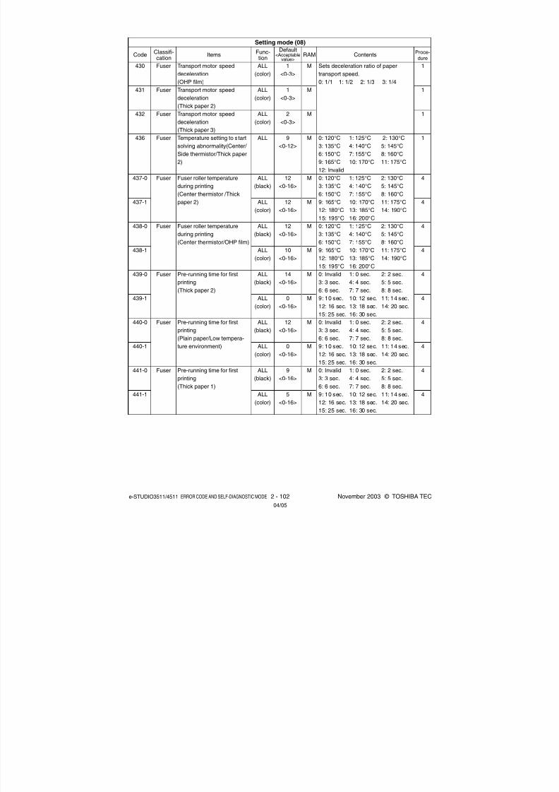
8/2/2019 ES-3511 Service Handbook
http://slidepdf.com/reader/full/es-3511-service-handbook 122/543
e-STUDIO3511/4511 ERROR CODE AND SELF-DIAGNOSTIC MODE 2 - 102 November 2003 © TOSHIBA TEC
430
431
432
436
437-0
437-1
438-0
438-1
439-0
439-1
440-0
440-1
441-0
441-1
Sets deceleration ratio of paper
transport speed.
0: 1/1 1: 1/2 2: 1/3 3: 1/4
0: 120°C 1: 125°C 2: 130°C
3: 135°C 4: 140°C 5: 145°C
6: 150°C 7: 155°C 8: 160°C
9: 165°C 10: 170°C 11: 175°C
12: Invalid
0: 120°C 1: 125°C 2: 130°C
3: 135°C 4: 140°C 5: 145°C
6: 150°C 7: 155°C 8: 160°C
9: 165°C 10: 170°C 11: 175°C
12: 180°C 13: 185°C 14: 190°C
15: 195°C 16: 200°C
0: 120°C 1: 125°C 2: 130°C
3: 135°C 4: 140°C 5: 145°C
6: 150°C 7: 155°C 8: 160°C
9: 165°C 10: 170°C 11: 175°C
12: 180°C 13: 185°C 14: 190°C
15: 195°C 16: 200°C
0: Invalid 1: 0 sec. 2: 2 sec.
3: 3 sec. 4: 4 sec. 5: 5 sec.
6: 6 sec. 7: 7 sec. 8: 8 sec.
9: 10 sec. 10: 12 sec. 11: 14 sec.12: 16 sec. 13: 18 sec. 14: 20 sec.
15: 25 sec. 16: 30 sec.
0: Invalid 1: 0 sec. 2: 2 sec.
3: 3 sec. 4: 4 sec. 5: 5 sec.
6: 6 sec. 7: 7 sec. 8: 8 sec.
9: 10 sec. 10: 12 sec. 11: 14 sec.
12: 16 sec. 13: 18 sec. 14: 20 sec.
15: 25 sec. 16: 30 sec.
0: Invalid 1: 0 sec. 2: 2 sec.
3: 3 sec. 4: 4 sec. 5: 5 sec.
6: 6 sec. 7: 7 sec. 8: 8 sec.
9: 10 sec. 10: 12 sec. 11: 14 sec.12: 16 sec. 13: 18 sec. 14: 20 sec.
15: 25 sec. 16: 30 sec.
1
1
1
1
4
4
4
4
4
4
4
4
4
4
ALL
(color)
ALL
(color)
ALL
(color)
ALL
ALL
(black)
ALL
(color)
ALL
(black)
ALL
(color)
ALL
(black)
ALL(color)
ALL
(black)
ALL
(color)
ALL
(black)
ALL(color)
1
<0-3>
1
<0-3>
2
<0-3>
9
<0-12>
12
<0-16>
12
<0-16>
12
<0-16>
10
<0-16>
14
<0-16>
0<0-16>
12
<0-16>
0
<0-16>
9
<0-16>
5<0-16>
Fuser
Fuser
Fuser
Fuser
Fuser
Fuser
Fuser
Fuser
Fuser
Transport motor speed
deceleration
(OHP film)
Transport motor speed
deceleration(Thick paper 2)
Transport motor speed
deceleration
(Thick paper 3)
Temperature setting to start
solving abnormality(Center/
Side thermistor/Thick paper
2)
Fuser roller temperature
during printing
(Center thermistor /Thick
paper 2)
Fuser roller temperature
during printing
(Center thermistor/OHP film)
Pre-running time for first
printing
(Thick paper 2)
Pre-running time for first
printing
(Plain paper/Low tempera-
ture environment)
Pre-running time for first
printing
(Thick paper 1)
Setting mode (08)
CodeClassifi-cation
ItemsFunc-tion
Default<Acceptable
value>RAM Contents
Proce-dure
M
M
M
M
M
M
M
M
M
M
M
M
M
M
04/05

8/2/2019 ES-3511 Service Handbook
http://slidepdf.com/reader/full/es-3511-service-handbook 123/543
November 2003 © TOSHIBA TEC 2 - 103 e-STUDIO3511/4511 ERROR CODE AND SELF-DIAGNOSTIC MODE
6
<0-11>
7
<0-11>
9
<0-11>
8
<0-11>
0
<0-1>
5
<0-5>
5
<0-5>
5
<0-5>
5
<0-5>
5
<0-5>
5<0-5>
5
<0-5>
5
<0-5>
5
<0-5>
5
<0-5>
M
M
M
M
M
M
M
M
M
M
M
M
M
M
M
0: 0°C 1: 5°C 2: 9°C 3: 10°C
4: 12°C 5: 14°C 6: 15°C 7: 16°C
8: 17°C 9: 18°C 10: 19°C 11: 20°C
0: No warming-up 1: 30 sec.
2: 40 sec. 3: 50 sec. 4: 60 sec.5: 70 sec. 6: 80 sec. 7: 90 sec.
8: 100 sec. 9: 120 sec. 10: 180 sec.
11: 300 sec.
0: 0°C 1: 5°C 2: 9°C 3: 10°C
4: 12°C 5: 14°C 6: 15°C 7: 16°C
8: 17°C 9: 18°C 10: 19°C 11: 20°C
0: Invalid (always) 1: 0 min.
2: 0.5 min. 3: 1 min. 4: 2 min.
5: 3 min. 6: 5 min. 7: 7 min.
8: 10 min. 9: 15 min.
10: 30 min. 11: 60 min.
Sets whether or not detecting the
original length by transporting without
scanning in reverse when finding A4-
R/FOLIO paper.
0: Invalid- Judges as A4-R without
transporting in reverse with no
scanning.
1: Valid- Judges whether it is A4-R or
FOLIO size by transporting in
reverse with no scanning.
* The original is transported in
reverse with no scanning when
detecting LT-LG size-paper in LT,regardless of this setting.
Sets the number of times of the
feeding retry from the upper drawer.
Sets the number of times of the
feeding retry from the lower drawer.
Sets the number of times of the
feeding retry from the PFP upper
drawer.
Sets the number of times of the
feeding retry from the PFP lower
drawer.
Sets the number of times of the
feeding retry from the bypass tray.
1
1
1
1
1
4
4
4
4
4
4
4
4
4
4
458
459
460
461
462
463-0
463-1
464-0
464-1
465-0
465-1
466-0
466-1
467-0
467-1
Fuser
Fuser
Fuser
Fuser
RADF
Paper
feeding
Paper
feeding
Paper
feeding
Paper
feeding
Paper
feeding
ALL
ALL
ALL
ALL
ALL
ALL
ALL
ALL
ALL
ALL
ALL
ALL
ALL
ALL
ALL
Threshold for warming-up
temperature(Low-tempera-
ture environment)
Warming-up time(Low-
temperature environment)
Threshold of temperature for
pre-running time for first
printing(Low-temperature
environment)
Pre-running time for first
printing(Plain paper/Low-
temperature environment)
Setting for switchback
operation to copy mixed-
sized original on RADF
Feeding retry
number setting
(upper drawer)
Feeding retry
number setting
(lower drawer)
Feeding retry
number setting
(PFP upperdrawer)
Feeding retry
number setting
(PFP lower
drawer)
Feeding retry
number setting
(bypass feed)
Setting mode (08)
CodeClassifi-cation
ItemsFunc-tion
Default<Acceptable
value>RAM Contents
Proce-dure
Plain
paper
Others
Plain
paper
Others
Plain
paper
Others
Plain
paper
Others
Plain
paper
Others
04/05

8/2/2019 ES-3511 Service Handbook
http://slidepdf.com/reader/full/es-3511-service-handbook 124/543
e-STUDIO3511/4511 ERROR CODE AND SELF-DIAGNOSTIC MODE 2 - 104 November 2003 © TOSHIBA TEC
Feeding retry
number setting
(LCF)
Paper size (305x457 mm)feeding/widthwise direction
Paper size (Post card)
feeding/widthwise direction
Judged number of polygonal
motor rotation error (Normal
rotation)
Judged number of polygonal
motor rotation error (At
acceleration/deceleration)
Default setting of paper
source
Automatic change of paper
source
Feeding retry setting
Pre-running rotation of
polygonal motor
ALL
ALL
ALL
ALL
ALL
ALL
PPC
PPC
ALL
ALL
5
<0-5>
5
<0-5>
457/305<148-457/
105-305>
148/100
<148-432/
100-297>
0
<0-1>
0
<0-1>
0
<0-5>
1
<0-2>
0
<0-1>
0
<0-2>
M
M
M
M
M
M
M
SYS
M
SYS
Sets the number of times of the
feeding retry from the LCF.
* Post card is supported only for JPN
model.
Displays the error [CA10] when the
set number of rotation error has been
detected.
0: 2 times 1: 12 times
0: Waiting time for polygonal motor
rotation overshooting 0.6 sec.
1: Waiting time for polygonal motor
rotation overshooting 2.2 sec.
0: A4/LT 1: LCF
2: Upper drawer 3: Lower drawer
4: PFP upper drawer
5: PFP lower drawer
Sets whether or not changing the
drawer automatically to the other
drawer with the paper of the same
size when paper in the selected
drawer has run out.
0: OFF
1: ON (Changes to the drawer with
the same paper direction and size:ex. A4 to A4)
2: ON (Changes to the drawer with
the same paper size. Paper with
the different direction is acceptable
as long as the size is the same:
ex., A4 to A4-R, LT-R to LT. “1” is
applied when the staple/hole-
punch is specified.)
0: ON 1: OFF
Sets whether or not switching the
polygonal motor from the standbyrotation to the normal rotation when
the original is set on the RADF or the
platen cover is opened.
0: Valid (when using RADF and the
original is set manually)
1: Invalid
2: Valid (when using RADF only)
Paper
feeding
Paperfeeding
Paper
feeding
Laser
Laser
Paper
feeding
Paper
feeding
Paper
feeding
Laser
Setting mode (08)
CodeClassifi-cation
ItemsFunc-tion
Default<Acceptable
value>RAM Contents
Proce-dure
468-0
468-1
470
471
478
479
480
481
482
483
4
4
10
10
1
1
1
1
1
1
Plain
paper
Others
04/10

8/2/2019 ES-3511 Service Handbook
http://slidepdf.com/reader/full/es-3511-service-handbook 125/543
November 2003 © TOSHIBA TEC 2 - 105 e-STUDIO3511/4511 ERROR CODE AND SELF-DIAGNOSTIC MODE
ALL
ALL
ALL
ALL
ALL
ALL
ALL
ALL
(color)
PPC
(black)
PPC
(black)
ALL
ALL
(black)
ALL
(color)
ALL
0
<0-1>
0
<0-1>
0
<0-2>
0
<0-1>
3
<2-3>
5
<0-5>
0
<0-1>0
<0-1>
0
<0-1>
0
<0-1>
1
<0-1>
16
<0-16>
0
<0-16>
1
<0-1>
Sets whether or not switching the
polygonal motor from the normal
rotation to the standby rotation at the
Auto Clear Mode.
0: Valid 1: InvalidSets the rotational status of
polygonal motor on standby.
0: Rotated (The rotational speed is
set at 08-490.)
1: Stopped
Switches the polygonal motor to the
standby rotation when a certain
period of time has passed from the
pre-running. At this code, the period
to switch the status to the standby
rotation is set.
0: 15 sec. 1: 30 sec. 2: 45 sec.
* This setting is effective when “0” or
“2” is set at 08-483.
0: Performs only at no paper size is
designated
1: Performs regardless of designa-
tion of paper size
Set the type of polygonal motor.
2: 2 clock type 3: 3 clock type
0: 38090.55rpm 1: 35000rpm
2: 30000rpm 3: 25000rpm
4: 20000rpm 5: 10000rpm
0: Stopped 1: 10000rpm
Sets the speed for color printing.
0: 11 pages/minute
1: 6 pages/minute
Sets the image reproduction method
at photo mode.
0: Error diffusion 1: Dither
0: Automatic
1: Manual (Center)
0: Invalid
1: Valid
0: Invalid 1: 0 sec. 2: 2 sec.
3: 3 sec. 4: 4 sec. 5: 5 sec.6: 6 sec. 7: 7 sec. 8: 8 sec.
9: 10 sec. 10: 12 sec. 11: 14 sec.
12: 16 sec. 13: 18 sec. 14: 20 sec.
15: 25 sec. 16: 30 sec.
Sets whether or not correcting the 1st
transfer roller bias depending on the
environment.
0: Invalid 1: Valid
1
1
1
1
1
1
1
1
1
1
1
4
4
1
SYS
SYS
SYS
M
M
M
M
M
SYS
SYS
M
M
M
M
484
485
486
487
488
489
490
497
502
503
511
526-0
526-1
541
Laser
Laser
Laser
Transfer
Laser
Laser
Laser
General
Image
User
interface
Main
charger
Fuser
Image
control
Polygonal motor rotational
status switching at the Auto
Clear Mode
Rotational status of
polygonal motor on standby
Timing of auto-clearing of
polygonal motor pre-running
rotation
Selection of performing the
2nd transfer roller cleaning
(Bypass feed)
Setting of polygonal motor
type
Polygonal motor rotation
number on standby
Polygonal motor rotation in
the energy saving modeSpeed switching for color
printing
Error diffusion and dither
setting at photo mode
Default setting of density
adjustment
Main charger wire auto-
cleaning setting
Pre-running time for first
printing(OHP film)
Environment correction
control of 1st transfer roller
bias
Setting mode (08)
CodeClassifi-cation
ItemsFunc-tion
Default<Acceptable
value>RAM Contents
Proce-dure
04/10

8/2/2019 ES-3511 Service Handbook
http://slidepdf.com/reader/full/es-3511-service-handbook 126/543
e-STUDIO3511/4511 ERROR CODE AND SELF-DIAGNOSTIC MODE 2 - 106 November 2003 © TOSHIBA TEC
Image
control
Imagecontrol
Image
control
Image
control
Image
control
Transfer
Image
control
Image
Image
control
Image
control
Image
control
Image
control
Transfer belt life correction
of 1st transfer roller bias
1st transfer roller lifecorrection of 1st transfer
roller bias
Environment correction
control of 2nd transfer roller
bias
Transfer belt life correction
of 2nd transfer roller bias
2nd transfer roller life
correction of 2nd transfer
roller bias
Setting of 2nd transfer roller
bias table (for each
destination/paper thickness)
Image quality control/open-
loop control 1
Default setting of Original
modeImage quality control/open-
loop control 2
Drum life correction control
Drum temperature correc-
tion control
Image quality open-loop
control/Contrast voltage
initial value
ALL
ALL
ALL
ALL
ALL
ALL
ALL
PPC
(black)ALL
ALL
ALL
ALL
1
<0-1>
1<0-1>
1
<0-1>
1
<0-1>
1
<0-1>
2
<0-2>
1
<0-1>
0
<0-3>1
<0-1>
1
<0-1>
1
<0-1>
1
<0-1>
M
M
M
M
M
M
M
SYS
M
M
M
M
Sets whether or not correcting the 1st
transfer roller bias depending on the
transfer belt life.
0: Invalid 1: Valid
Sets whether or not correcting the 1sttransfer roller bias depending on the
1st transfer roller life.
0: Invalid 1: Valid
Sets whether or not correcting the
2nd transfer roller bias depending on
the environment.
0: Invalid 1: Valid
Sets whether or not correcting the
2nd transfer roller bias depending on
the transfer belt life.
0: Invalid 1: Valid
Sets whether or not correcting the
2nd transfer roller bias depending on
the 2nd transfer roller life.
0: Invalid 1: Valid
0:80 g/m2 (21.3 lb.)/EUR
1:75 g/m2 (20 lb.)/UC
2:64 g/m2 (17.1 lb.)/JPN
Sets whether or not performing the
open-loop control 1.The open-loop
control 1 is performed in advance of
the closed-loop control.
0: Invalid 1: Valid
0: Text/Photo 1: Photo 2: Text
3: Gray ScaleSets whether or not performing the
open-loop control 2.The open-loop
control 2 is performed before or
during printing.
0: Invalid 1: Valid
Sets whether or not correcting the
drum voltage depending on the drum
life in open-loop control.
0: Invalid 1: Valid
Sets whether or not correcting the
drum voltage depending on the drum
surface temperature in open-loopcontrol.
0: Invalid 1: Valid
Sets whether or not deciding the
initial value of contrast voltage in
open-loop control.
0: Invalid 1: Valid
1
1
1
1
1
1
1
1
1
1
1
1
542
543
544
545
546
548
549
550
551
552
553
554
Setting mode (08)
CodeClassifi-cation
ItemsFunc-tion
Default<Acceptable
value>RAM Contents
Proce-dure
04/09

8/2/2019 ES-3511 Service Handbook
http://slidepdf.com/reader/full/es-3511-service-handbook 127/543
November 2003 © TOSHIBA TEC 2 - 107 e-STUDIO3511/4511 ERROR CODE AND SELF-DIAGNOSTIC MODE
Image
control
Image
control
Image
control
Image
control
Image
control
Image
Image
Image
Image
control
Image
control
Image
control
Drum life correction of laser
power initial value
Image quality closed-loop
control/Contrast voltage
Image quality closed-loop
control/Laser power
Contrast voltage/Correction
gain environment setting
Image quality closed-loop
control automatic start-up/At
power-ON
Process switching for image
smoothing (Text/Photo)
Process switching for image
smoothing (Photo)
Process switching for image
smoothing (Text)
Image quality closed-loop
control automatic start-up/
Relative humidity variation
Image quality closed-loop
control automatic start-up/ Period of time unattended
Image quality closed-loop
control automatic start-up/
Accumulated print volume
Sets whether or not correcting the
laser power depending on the drum
life when the laser power initial value
is set in open-loop control.
0: Invalid 1: ValidSets whether or not correcting the
contrast voltage in closed-loop
control.
0: Invalid 1: Valid
Sets whether or not correcting the
laser power in closed-loop control.
0: Invalid 1: Valid
Sets whether or not switching the
correction amount once at contrast
voltage correction depending on the
environment.
0: Invalid 1: Valid
Sets whether performing closed-loop
control automatically at power-ON
when the fuser roller temperature
becomes below the specified level.
0: Invalid 1: Valid (at mode 1)
2: Valid (at mode 2)
Sets whether or not performing a
smoothing process (primary scanning
direction, 2,400 dpi or equivalent).
0: Invalid 1: Valid
Sets whether or not performing a
smoothing process (primary scanning
direction, 2,400 dpi or equivalent).0: Invalid 1: Valid
Sets whether or not performing
closed-loop control automatically
when the relative humidity becomes
below the specified level from the
previous control.
0: Invalid 1: Valid (at mode 1)
2: Valid (at mode 2)
Sets whether or not performing
closed-loop control automaticallywhen the equipment has not been
used for a specified period of time.
0: Invalid 1: Valid (at mode 1)
2: Valid (at mode 2)
Sets whether or not performing
closed-loop control automatically
when the specified number of sheets
has been printed out from the
previous control.
0: Invalid 1: Valid (at mode 1)
2: Valid (at mode 2)
1
1
1
1
1
1
1
1
1
1
1
1
<0-1>
1
<0-1>
1
<0-1>
1
<0-1>
1
<0-2>
1
<0-1>
0
<0-1>
1
<0-1>
1
<0-2>
1
<0-2>
2
<0-2>
M
M
M
M
M
M
M
M
M
M
M
ALL
ALL
ALL
ALL
ALL
(color)
PPC
(black)
PPC
(black)
PPC
(black)
ALL
(color)
ALL
(color)
ALL
(color)
555
556
557
558
559
560
561
562
565
566
567
Setting mode (08)
CodeClassifi-cation
ItemsFunc-tion
Default<Acceptable
value>RAM Contents
Proce-dure
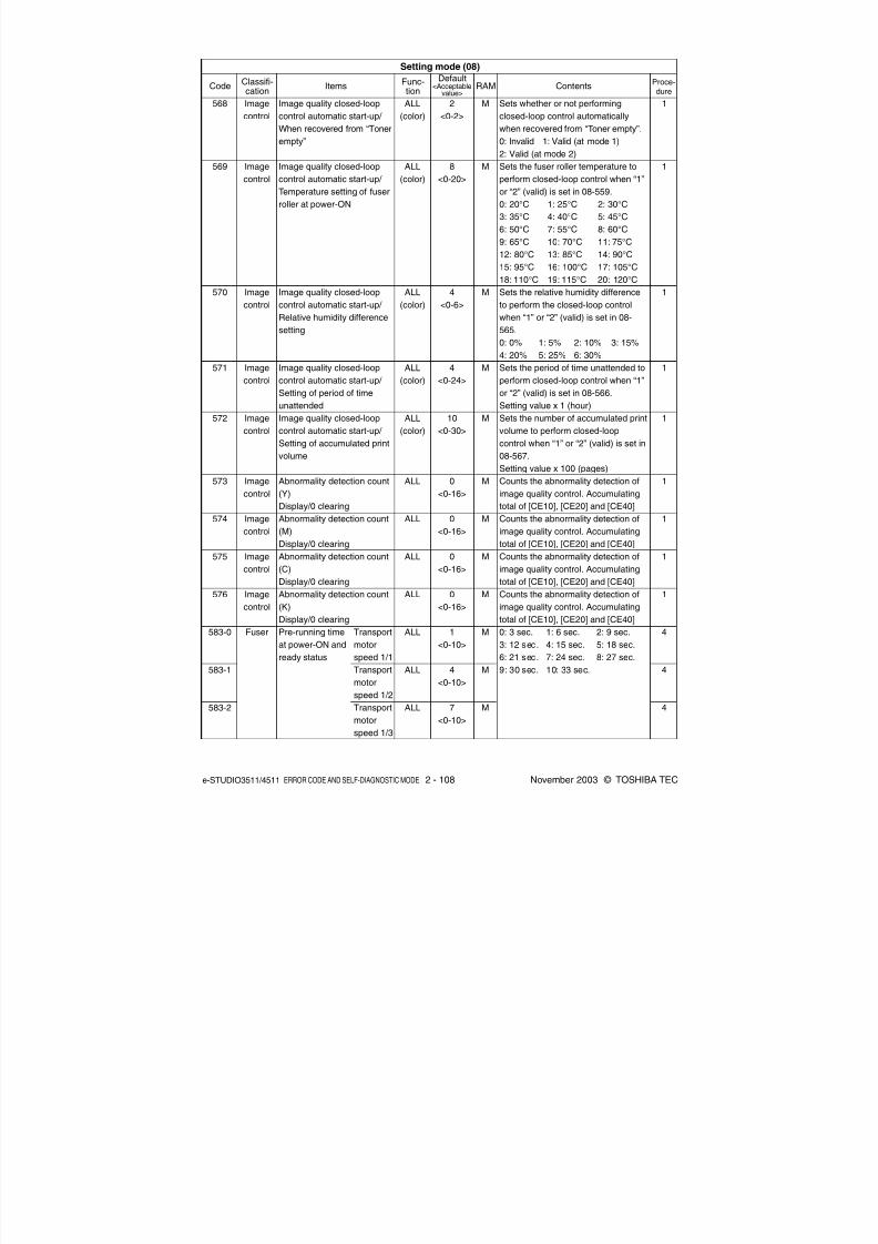
8/2/2019 ES-3511 Service Handbook
http://slidepdf.com/reader/full/es-3511-service-handbook 128/543
e-STUDIO3511/4511 ERROR CODE AND SELF-DIAGNOSTIC MODE 2 - 108 November 2003 © TOSHIBA TEC
568
569
570
571
572
573
574
575
576
583-0
583-1
583-2
Image
control
Image
control
Image
control
Image
control
Image
control
Image
control
Image
control
Image
control
Image
control
Fuser
Image quality closed-loop
control automatic start-up/
When recovered from “Toner
empty”
Image quality closed-loop
control automatic start-up/
Temperature setting of fuser
roller at power-ON
Image quality closed-loop
control automatic start-up/
Relative humidity difference
setting
Image quality closed-loop
control automatic start-up/
Setting of period of time
unattended
Image quality closed-loop
control automatic start-up/
Setting of accumulated print
volume
Abnormality detection count
(Y)
Display/0 clearing
Abnormality detection count
(M)
Display/0 clearing
Abnormality detection count
(C)
Display/0 clearing
Abnormality detection count
(K)
Display/0 clearingPre-running time
at power-ON and
ready status
ALL
(color)
ALL
(color)
ALL
(color)
ALL
(color)
ALL
(color)
ALL
ALL
ALL
ALL
ALL
ALL
ALL
2
<0-2>
8
<0-20>
4
<0-6>
4
<0-24>
10
<0-30>
0
<0-16>
0
<0-16>
0
<0-16>
0
<0-16>
1
<0-10>
4
<0-10>
7
<0-10>
M
M
M
M
M
M
M
M
M
M
M
M
Sets whether or not performing
closed-loop control automatically
when recovered from “Toner empty”.
0: Invalid 1: Valid (at mode 1)
2: Valid (at mode 2)Sets the fuser roller temperature to
perform closed-loop control when “1”
or “2” (valid) is set in 08-559.
0: 20°C 1: 25°C 2: 30°C
3: 35°C 4: 40°C 5: 45°C
6: 50°C 7: 55°C 8: 60°C
9: 65°C 10: 70°C 11: 75°C
12: 80°C 13: 85°C 14: 90°C
15: 95°C 16: 100°C 17: 105°C
18: 110°C 19: 115°C 20: 120°C
Sets the relative humidity difference
to perform the closed-loop control
when “1” or “2” (valid) is set in 08-
565.
0: 0% 1: 5% 2: 10% 3: 15%
4: 20% 5: 25% 6: 30%
Sets the period of time unattended to
perform closed-loop control when “1”
or “2” (valid) is set in 08-566.
Setting value x 1 (hour)
Sets the number of accumulated print
volume to perform closed-loop
control when “1” or “2” (valid) is set in
08-567.
Setting value x 100 (pages)Counts the abnormality detection of
image quality control. Accumulating
total of [CE10], [CE20] and [CE40]
Counts the abnormality detection of
image quality control. Accumulating
total of [CE10], [CE20] and [CE40]
Counts the abnormality detection of
image quality control. Accumulating
total of [CE10], [CE20] and [CE40]
Counts the abnormality detection of
image quality control. Accumulating
total of [CE10], [CE20] and [CE40]0: 3 sec. 1: 6 sec. 2: 9 sec.
3: 12 sec. 4: 15 sec. 5: 18 sec.
6: 21 sec. 7: 24 sec. 8: 27 sec.
9: 30 sec. 10: 33 sec.
1
1
1
1
1
1
1
1
1
4
4
4
Setting mode (08)
CodeClassifi-cation
ItemsFunc-tion
Default<Acceptable
value>RAM Contents
Proce-dure
Transport
motor
speed 1/1
Transport
motor
speed 1/2
Transport
motor
speed 1/3

8/2/2019 ES-3511 Service Handbook
http://slidepdf.com/reader/full/es-3511-service-handbook 129/543
November 2003 © TOSHIBA TEC 2 - 109 e-STUDIO3511/4511 ERROR CODE AND SELF-DIAGNOSTIC MODE
0: Decelerating to 1/1
1: Decelerating to 1/2
2: Decelerating to 1/3
0: Text/Photo 1: Text
2: Printed image 3: Photo4: Map
Selects the method of image
processing when the Image Smooth-
ing is selected in the original modes.
0: Processing for Image Smoothing
1: Processing when judging as black
in the ACS Mode
0: Automatic
1: Manual (Center)
0: Auto color 1: Black
2: Full color
Selects the method of image
processing when the original is
judged as black in the ACS Mode.
0: Processing for Image Smoothing
1: Processing when judging as black
in the ACS Mode
0: Scanning color/black integrated
pattern
1: Scanning color pattern only
Initializes the status of automatic
gamma adjustment in color printing.
0: OFF 1: ON
0: Invalid
1: Single-sided to duplex copying
2: Two-sided to duplex copying
3: User selection
0: APS (Automatic Paper Selection)
1: AMS (Automatic Magnification
Selection)
2: Not selected
0: Invalid 1: Valid
0: Continuous feeding(by pressing the [START] button)
1: Single feeding
(by setting original on the tray)
1
1
1
1
1
1
1
3
1
1
1
1
1
M
SYS
SYS
SYS
SYS
SYS
SYS
SYS
SYS
SYS
SYS
SYS
SYS
0
<0-2>
0
<0-4>
0
<0-1>
1
<0-1>
1
<0-2>
1
<0-1>
0
<0-1>
-
EUR:0
UC:1
JPN:1<0-1>
0
<0-3>
0
<0-2>
0
<0-1>
0<0-1>
ALL
PPC
(color)
PPC
(black)
PPC
(color)
PPC
PPC
(black)
PPC
(Color)
PRT
(color)
ALL
ALL
ALL
PPC
PPC
584
585
586
587
588
589
595
597
602
603
604
605
607
Fuser
User
interface
Image
User
interface
User
interface
Image
Image
Image
User
interface
User
interface
User
interface
User
interface
Userinterface
Transport motor speed of
pre-running at ready status
Default setting of Original
mode
Image quality switching
when selecting the Image
Smoothing Mode
Default setting of Density
mode
Default setting of Color
mode
Image quality switching
when judging as black in the
ACS Mode
Scanning operation
switching at automatic
calibration
Gamma correction table all
clearing
Screen setting for automatic
energy saver/automatic
power OFF
Setting for automatic
duplexing mode
Default setting for APS/AMS
Centering printing of primary/
secondary direction at AMS
Default setting of RADFmode
Setting mode (08)
CodeClassifi-cation
ItemsFunc-tion
Default<Acceptable
value>RAM Contents
Proce-dure
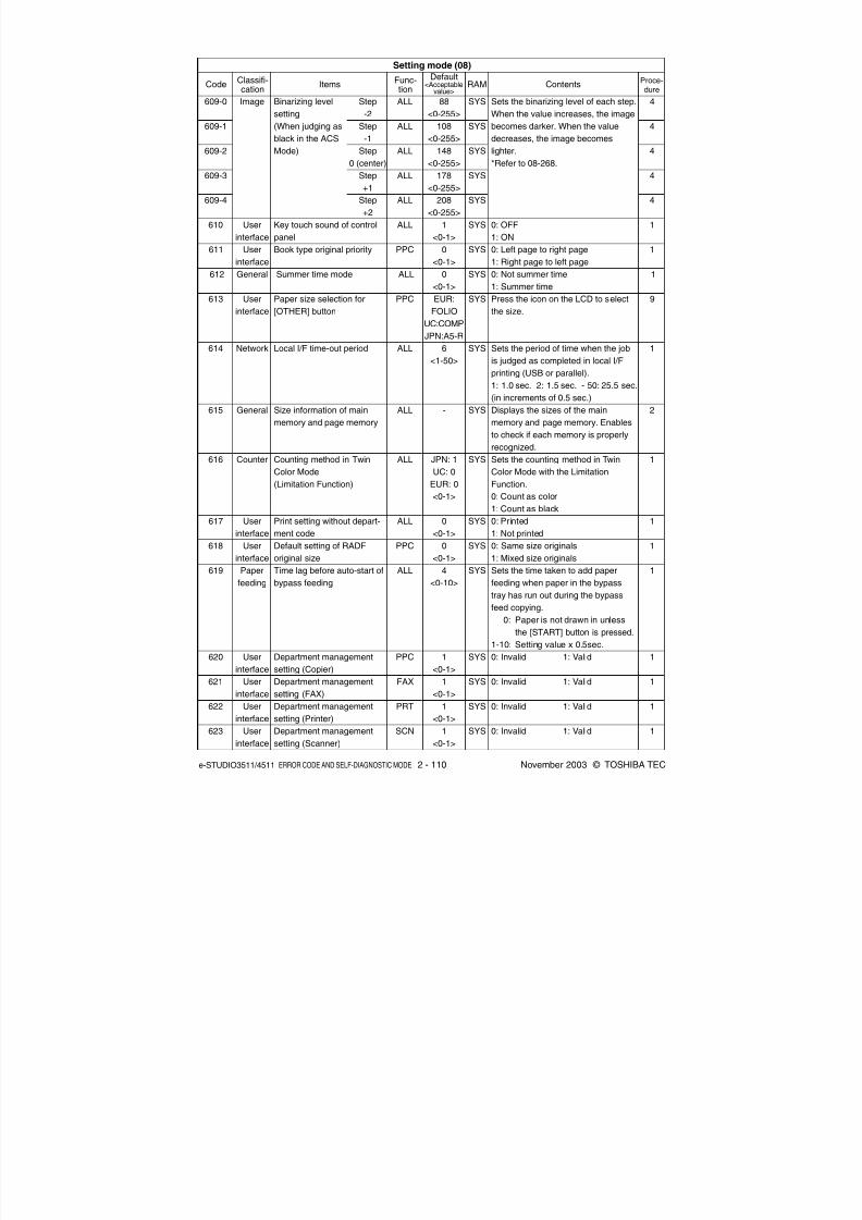
8/2/2019 ES-3511 Service Handbook
http://slidepdf.com/reader/full/es-3511-service-handbook 130/543
e-STUDIO3511/4511 ERROR CODE AND SELF-DIAGNOSTIC MODE 2 - 110 November 2003 © TOSHIBA TEC
Binarizing level
setting
(When judging as
black in the ACS
Mode)
Key touch sound of control
panel
Book type original priority
Summer time mode
Paper size selection for
[OTHER] button
Local I/F time-out period
Size information of main
memory and page memory
Counting method in TwinColor Mode
(Limitation Function)
Print setting without depart-
ment code
Default setting of RADF
original size
Time lag before auto-start of
bypass feeding
Department management
setting (Copier)
Department management
setting (FAX)
Department management
setting (Printer)
Department management
setting (Scanner)
Sets the binarizing level of each step.
When the value increases, the image
becomes darker. When the value
decreases, the image becomes
lighter.*Refer to 08-268.
0: OFF
1: ON
0: Left page to right page
1: Right page to left page
0: Not summer time
1: Summer time
Press the icon on the LCD to select
the size.
Sets the period of time when the job
is judged as completed in local I/F
printing (USB or parallel).
1: 1.0 sec. 2: 1.5 sec. - 50: 25.5 sec.
(in increments of 0.5 sec.)
Displays the sizes of the main
memory and page memory. Enables
to check if each memory is properly
recognized.
Sets the counting method in TwinColor Mode with the Limitation
Function.
0: Count as color
1: Count as black
0: Printed
1: Not printed
0: Same size originals
1: Mixed size originals
Sets the time taken to add paper
feeding when paper in the bypass
tray has run out during the bypass
feed copying.0: Paper is not drawn in unless
the [START] button is pressed.
1-10: Setting value x 0.5sec.
0: Invalid 1: Valid
0: Invalid 1: Valid
0: Invalid 1: Valid
0: Invalid 1: Valid
4
4
4
4
4
1
1
1
9
1
2
1
1
1
1
1
1
1
1
ALL
ALL
ALL
ALL
ALL
ALL
PPC
ALL
PPC
ALL
ALL
ALL
ALL
PPC
ALL
PPC
FAX
PRT
SCN
88
<0-255>
108
<0-255>
148<0-255>
178
<0-255>
208
<0-255>
1
<0-1>
0
<0-1>
0
<0-1>
EUR:
FOLIO
UC:COMP
JPN:A5-R
6
<1-50>
-
JPN: 1UC: 0
EUR: 0
<0-1>
0
<0-1>
0
<0-1>
4
<0-10>
1
<0-1>
1
<0-1>
1
<0-1>
1
<0-1>
SYS
SYS
SYS
SYS
SYS
SYS
SYS
SYS
SYS
SYS
SYS
SYS
SYS
SYS
SYS
SYS
SYS
SYS
SYS
609-0
609-1
609-2
609-3
609-4
610
611
612
613
614
615
616
617
618
619
620
621
622
623
Image
User
interface
User
interface
General
User
interface
Network
General
Counter
User
interface
User
interface
Paper
feeding
User
interface
User
interface
User
interface
User
interface
Setting mode (08)
CodeClassifi-cation
ItemsFunc-tion
Default<Acceptable
value>RAM Contents
Proce-dure
Step
-2
Step
-1
Step0 (center)
Step
+1
Step
+2

8/2/2019 ES-3511 Service Handbook
http://slidepdf.com/reader/full/es-3511-service-handbook 131/543
November 2003 © TOSHIBA TEC 2 - 111 e-STUDIO3511/4511 ERROR CODE AND SELF-DIAGNOSTIC MODE
0: Invalid 1: Valid
0: OFF
1: ON (Start printing when the
scanning of each page is finished)0: Not rotating 1: Rotating
0: Automatic 1: Portrait
0: Invalid 1: Valid
Sets the disclosing level of automatic
calibration.
0: Service technician
1: Administrator 2: User
0: Normal
1: Inner receiving tray
0: ON 1: OFF
0: +12.0h 1: +11.5h 2: +11.0h
3: +10.5h 4: +10.0h 5: 9.5h
6: +9.0h 7: +8.5h 8: +8.0h
9: +7.5h 10: +7.0h 11: +6.5h
12: +6.0h 13: +5.5h 14: +5.0h
15: +4.5h 16: +4.0h 17: +3.5h
18: +3.0h 19: +2.5h 20: +2.0h
21: +1.5h 22: +1.0h 23: +0.5h
24: 0.0h 25:-0.5h 26: -1.0h
27: -1.5h 28: -2.0h 29: -2.5h30: -3.0h 31: -3.5h 32: -4.0h
33: -4.5h 34: -5.0h 35: -5.5h
36: -6.0h 37: -6.5h 38: -7.0h
39: -7.5h 40: -8.0h 41: -8.5h
42: -9.0h 43: -9.5h 44: -10.0h
45: -10.5h 46: -11.0h 47: -11.5h
0: YYYY.MM.DD. 1: DD.MM.YYYY
2: MM.DD.YYYY
0: Invalid 1: STAPLE
2:SORT 3: GROUP4: ROTATE SORT
0: NON-SORT 1: STAPLE
2: SORT 3: GROUP
4: ROTATE SORT
0: K 1: Y 2: M 3: C
4: R 5: G 6: B
0: K 1: Y 2: M 3: C
4: R 5: G 6: B
1
1
1
1
1
1
1
1
1
1
1
1
1
1
PRT
PPC
ALL
PPC
ALL
PPC
ALL
PPC
ALL
ALL
PPC
PPC
PPC
(color)
PPC
(color)
1
<0-1>
0
<0-1>
0
<0-1>
0
<0-1>
0
<0-1>
1
<0-2>
0
<0-1>
0
<0-1>
EUR: 24
UC: 40
JPN: 6
<0-47>
EUR:1
UC:2
JPN:0
<0-2>
2
<0-4>
0
<0-4>
0
<0-6>
4
<0-6>
SYS
SYS
SYS
SYS
SYS
SYS
SYS
SYS
SYS
SYS
SYS
SYS
SYS
SYS
Department management
setting (List print)
Blank copying prevention
mode during RADF jamming
Rotation printing at the non-
sorting
Direction priority of original
image
Department management
setting
Automatic calibration
disclosure level
Inner receiving tray priority
at Non-sort Mode
Width setting for image shift
copying (linkage of front side
and back side)
Time differences
Date display format
Automatic Sorting Mode
setting (RADF)
Default setting of Sorter
Mode
Color 1 at twin color
selection (Select what color
black in original is copied)
Color 2 at twin color
selection (Select what color
other than black in original is
copied)
624
625
627
628
629
632
634
636
638
640
641
642
643
644
User
interface
User
interface
User
interface
User
interface
User
interface
User
interface
User
interface
User
interface
General
User
interface
User
interface
User
interface
User
interface
User
interface
Setting mode (08)
CodeClassifi-cation
ItemsFunc-tion
Default<Acceptable
value>RAM Contents
Proce-dure
04/09

8/2/2019 ES-3511 Service Handbook
http://slidepdf.com/reader/full/es-3511-service-handbook 132/543
e-STUDIO3511/4511 ERROR CODE AND SELF-DIAGNOSTIC MODE 2 - 112 November 2003 © TOSHIBA TEC
Sets the reproduction ratio for the “X
in 1” printing (including magazine
sort) to the “Reproduction ratio x
Correction ratio”.
0: 90% 1: 91% 2: 92% 3: 93%4: 94% 5: 95% 6: 96% 7: 97%
8: 98% 9: 99% 10: 100%
Sets the page pasted position for “X
in 1” to the upper left corner/center.
0: Cornering 1: Centering
0: Rotation OFF
1: Rotation ON
Sets whether or not returning the
finisher tray to the bin 1 when printing
is finished.
0: Not returned 1: Returned
0: Left page to right page
1: Right page to left page
0: Horizontal
1: Vertical
Hyphen Dropout
(with page number)(with date, time and page number)
0: OFF OFF
1: ON OFF
2: OFF ON
3: ON ON
Note: Hyphen printing format
ON: -1- OFF: 1
0: OFF 1: ON
0: OFF 1: ON
0: Short edge
1: Long edge
Sets whether or not feeding a paper
automatically into the copier when it
is placed on the bypass tray.
0: OFF (Press the [START] button to
start feeding.)
1: ON (Automatical feeding)
Sets whether or not feeding a paperautomatically into the copier when it
is placed on the bypass tray.
0: OFF (Press the [START] button to
start feeding.)
1: ON (Automatical feeding)
0: Invalid
1: Valid
0: Invalid
1: Valid
1
1
1
1
1
1
1
1
1
1
1
1
1
1
PPC
PPC
ALL
ALL
PPC
PPC
PPC
PPC
PRT
PPC
PRT
PPC
ALL
ALL
SYS
SYS
SYS
SYS
SYS
SYS
SYS
SYS
SYS
SYS
SYS
SYS
SYS
SYS
10
<0-10>
0
<0-1>
1
<0-1>
0
<0-1>
0
<0-1>
0
<0-1>
2
<0-3>
0
<0-1>0
<0-1>
0
<0-1>
0
<0-1>
1<0-1>
0
<0-1>
0
<0-1>
Correction of reproduction
ratio in editing copy
Image position in editing
Rotation of paper direction
for BOX printing
Returning finisher tray when
printing is finished
Magazine sort setting
2 in 1/4 in 1 page allocating
order setting
Printing format setting for
Time Stamp and Page
Number
Cascade operation setting
Cascade operation setting
Default setting of printing
direction for Time Stamp
and Page Number
Auto-start setting for bypass
feed printing
Auto-start setting for bypassfeed printing
Auto-forwarding setting of
received FAX
Auto-forwarding setting of
received E-mail
645
646
647
648
649
650
651
652
653
657
658
659
660
661
User
interface
User
interface
User
interface
User
interface
User
interface
User
interface
User
interface
User
interfaceUser
interface
User
interface
User
interface
Userinterface
Network
Network
Setting mode (08)
CodeClassifi-cation
ItemsFunc-tion
Default<Acceptable
value>RAM Contents
Proce-dure

8/2/2019 ES-3511 Service Handbook
http://slidepdf.com/reader/full/es-3511-service-handbook 133/543
November 2003 © TOSHIBA TEC 2 - 113 e-STUDIO3511/4511 ERROR CODE AND SELF-DIAGNOSTIC MODE
Clears SMS partition. (Performs
when the service call [F106] has
occurred.)
Sets the counting method of fee
charging or depar tment count in TwinColor Mode.
0: Count as Twin Color Mode
1: Count as Black Mode
2: Count as Full Color Mode
Initializes all the adjustment modes
and the setting modes.
Initializes the Electronic Filing.
Initializes the shared folder.
Initializes system NVRAM area.
Display the HDD information
0: Invalid 1: Valid
Initializing of the department man-
agement information
* Enter the code with the digital keys
and press the [INITIALIZE] button to
perform the initialization.
If the area storing the department
management information is
destroyed for some reason, “Enter
Department Code” is displayed on
the control panel even if the
department management function isnot set on. In this case, initialize the
area with this code. This area is
normally initialized at the factory.
Sets whether or not applying the
Coated Paper Mode to each paper
source.
0: Normal mode
1: Coated Paper Mode
* Coated Paper Mode - This mode is
selected when the paper which often
causes the misfeeding (ex. coated
paper) is used. The occurrence ofmisfeeding is reduced by lengthening
the jam detection time. However, the
printing speed is lowered since the
printing cycle is also lengthened with
the lengthened jam detection time.
3
1
3
3
3
3
2
1
3
4
4
4
4
4
-
0
<0-2>
-
-
-
-
-
0
<0-1>
-
0
<0-1>
0
<0-1>
0
<0-1>
0
<0-1>
0
<0-1>
SYS
SYS
M/
SYS
SYS
SYS
SYS
SYS
SYS
SYS
SYS
SYS
SYS
SYS
SYS
Clearing of SMS partition
Counting method in Twin
Color Mode
M/SYS all clearing
/SHR partition clearing
/SHA partition clearing
System all clearing
HDD diagnostic menu
display
Size indicator
Initialization of department
management information
Coated Paper
Mode setting for
paper source
ALL
PPC
ALL
ALL
ALL
ALL
ALL
ALL
-
ALL
ALL
ALL
ALL
ALL
662
663
665
666
667
669
670
671
672
675-0
675-1
675-2
675-3
675-4
General
Counter
General
General
General
General
General
User
interface
General
Paper
feeding
Setting mode (08)
CodeClassifi-cation
ItemsFunc-tion
Default<Acceptable
value>RAM Contents
Proce-dure
Upper
drawer
Lower
drawer
PFP
upper
drawerPFP
lower
drawer
LCF
04/10

8/2/2019 ES-3511 Service Handbook
http://slidepdf.com/reader/full/es-3511-service-handbook 134/543
e-STUDIO3511/4511 ERROR CODE AND SELF-DIAGNOSTIC MODE 2 - 114 November 2003 © TOSHIBA TEC
Sets whether or not displaying the
[COATED] button on the LCD screen
at bypass feeding.
0: Not displayed
1: Displayed (The Coated Paper Modeis applied by pressing the [COATED]
button at bypass feeding.)
* Coated Paper Mode - This mode is
selected when the paper which often
causes the misfeeding (ex. coated
paper) is used. The occurrence of
misfeeding is reduced by lengthening
the jam detection time. However, the
printing speed is lowered since the
printing cycle is also lengthened with
the lengthened jam detection time.
Sets whether or not applying the
Coated Paper Mode on each paper
type at bypass printing.
0: Normal mode
1: Coated Paper Mode
* Coated Paper Mode - This mode is
selected when the paper which
often causes the misfeeding (ex.
coated paper) is used. The occur-
rence of misfeeding is reduced by
lengthening the jam detection time.
However, the printing speed is
lowered since the printing cycle is
also lengthened with the lengthened jam detection time.
Sets whether or not displaying the
banner advertising. The setting
contents of 08-679 and 08-680 are
displayed at the time display section
on the right top of the screen. When
both are set, each content is dis-
played alternately.
0: Not displayed
1: DisplayedMaximum 27 letters
(one-byte character)
Maximum 27 letters
(one-byte character)
0: Not displayed 1: Displayed
* This button enables the entry of
“Banner advertising display 1(08-
679)” and “Banner advertising
display 2 (08-680)” on the control
panel.
0
<0-1>
0
<0-1>
0
<0-1>
0
<0-1>
0
<0-1>
0
<0-1>
0
<0-1>
0
<0-1>
-
-
0
<0-1>
SYS
SYS
SYS
SYS
SYS
SYS
SYS
SYS
SYS
SYS
SYS
Bypass copy printing
[COATED] button display
Coated Paper
Mode setting at
bypass feeding
Setting of banner advertis-
ing display
Banner advertising display 1
Banner advertising display 2
Display of [BANNER
MESSAGE] button
PPC
PRT
PRT
PRT
PRT
PRT
PRT
ALL
ALL
ALL
ALL
Paper
feeding
Paper
feeding
General
General
General
General
676
677-0
677-1
677-2
677-3
677-4
677-5
678
679
680
681
1
4
4
4
4
4
4
1
11
11
1
Setting mode (08)
CodeClassifi-cation
ItemsFunc-tion
Default<Acceptable
value>RAM Contents
Proce-dure
04/09
Plain
paper
Thick
paper 1
Thick
paper 2
Thick
paper 3
OHP film
Envelope

8/2/2019 ES-3511 Service Handbook
http://slidepdf.com/reader/full/es-3511-service-handbook 135/543
November 2003 © TOSHIBA TEC 2 - 115 e-STUDIO3511/4511 ERROR CODE AND SELF-DIAGNOSTIC MODE
0: Invalid 1: Valid
When the duplex printing is short
paid with a coin controller, reverse
side of the original is not printed andis considered as a defect (printing job
may be cleared). To solve this
problem, the selection of printing
method is enabled with this setting.
0: Invalid (Both sides printed)
1: Valid (Only one side printed)
Rebuilds all databases.
Rebuilds all databases related to the
Address Book.
Rebuilds all databases related to the
logs.
0: Not subjected for APS judgment
1: Subjected for APS judgment
2: Normal formatting
0: Not formatted 1: Not used
2: Normal format
Performs the calibration of the pressing
position on the touch panel (LCD
screen). The calibration is performed
by pressing 2 reference positions after
this code is started up.
Returns the value to the factory
shipping default value.Checks the bad sector.
0: Not installed
1: Installed
Sets the paper type priority during
copying.
1: Normal paper 2: Thick paper 1
Start up this code and have the user
enter the key code.
This setting is effective only when the
scrambler board is installed.
0: Japan 1: Asia
2: Australia 3: Hong Kong4: U.S.A./Canada 5: Germany
6: U.K. 7: Italy
8: Belgium 9: Netherlands
10: Finland 11: Spain
12: Austria 13: Switzerland
14: Sweden 15: Denmark
16: Norway 17: Portugal
18: France 19: Greece
20: Poland 21: Hungary
22: Czech 23: Turkey
24: South Africa 25: Taiwan
1
1
3
3
3
1
7
7
1
3
3
2
1
5
3
1
ALL
ALL
ALL
ALL
ALL
FAX
ALL
ALL
ALL
ALL
ALL
ALL
PPC
ALL
ALL
FAX
SYS
SYS
SYS
SYS
SYS
SYS
SYS
SYS
SYS
SYS
SYS
-
SYS
-
-
SYS
0
<0-1>
1
<0-1>
-
-
-
0
<0-1>
-
<2>
-
<0-2>
-
-
-
0
<0-1>
1
<1-2>
-
-
EUR: 5
UC: 4JPN: 0
Other: 1
<0-25>
682
683
684
685
686
689
690
691
692
693
694
696
697
698
699
701
User
interface
General
General
General
General
FAX
General
General
Mainte-
nance
General
General
Scrambler
board
Paper
feeding
Scrambler
board
Scrambler
board
FAX
Offsetting between jobs
Duplex printing setting when
coin controller is used
Rebuilding all databases
Rebuilding all databases
related to Address Book
Rebuilding all databases
related to log
Adaptation of paper source
priority selection
HDD formatting
HDD type display
Performing panel calibration
Initialization of NIC informa-
tionPerforming HDD testing
Installation of scrambler
board (Option)
Paper type priority
Entering the key code for
scrambler board
Erasing all data in HDD
Destination setting for FAX
Setting mode (08)
CodeClassifi-cation
ItemsFunc-tion
Default<Acceptable
value>RAM Contents
Proce-dure
04/09

8/2/2019 ES-3511 Service Handbook
http://slidepdf.com/reader/full/es-3511-service-handbook 136/543
e-STUDIO3511/4511 ERROR CODE AND SELF-DIAGNOSTIC MODE 2 - 116 November 2003 © TOSHIBA TEC
Remote-controlled service
function
Remote-controlled service
HTTP server
URL settingRemote-controlled service
HTTP initially-registered
server
URL setting
Short time interval setting of
recovery from Emergency
Mode
Short time interval setting of
Emergency Mode
Remote-controlled service
periodical polling timing
(Hour/Hour/Minute/Minute)
Remote-controlled service
Writing data of self-
diagnostic code
Remote-controlled service
response waiting time
(Timeout)
Remote-controlled service
initial registration
Remote-controlled service
tentative password
Status of remote-controlled
service initial registration(Display only)
Service center call function
Service center call
HTTP server URL setting
HTTP proxy setting
HTTP proxy IP address
setting
HTTP proxy port number
settingHTTP proxy ID setting
HTTP proxy password
setting
HTTP proxy panel display
Automatic ordering function
of supplies
702
703
707
710
711
715
716
717
718
719
720
721
723
726
727
728
729
730
731
732
Mainte-
nance
Mainte-
nance
Mainte-
nance
Mainte-
nance
Mainte-
nance
Mainte-
nance
Mainte-
nance
Mainte-
nance
Mainte-
nance
Mainte-
nance
Mainte-
nance
Mainte-
nance
Mainte-
nance
Mainte-
nance
Mainte-
nance
Mainte-
nanceMainte-
nance
Mainte-
nance
Mainte-
nance
Mainte-
nance
(Remote)
ALL
ALL
ALL
ALL
ALL
ALL
ALL
ALL
ALL
ALL
ALL
ALL
ALL
ALL
ALL
ALL
ALL
ALL
ALL
ALL
2
<0-2>
-
-
24
<1-48>
60
<30-360>
-
0
<0-1>
3
<1-30>
0
<0-1>
-
0
<0-1>
2
<0-2>
-
1
<0-1>
-
0
<0-65535>-
-
1
<0-1>
3
<0-3>
SYS
SYS
SYS
SYS
SYS
SYS
SYS
SYS
SYS
SYS
SYS
SYS
SYS
SYS
SYS
SYS
SYS
SYS
SYS
SYS
0: Valid (Remote-controlled server)
1: Valid (L2) 2: Invalid
Maximum 256 Bytes
Maximum 256 Bytes
Sets the time interval to recover from
the Emergency Mode to the Normal
Mode.
(Unit: Hour)
Unit: Minute
0 (0:00) to 2359 (23:59)
0: Prohibited 1: Accepted
Unit: Minute
0: OFF 1: Start
2: Only certification is scanned
Maximum 10 letters
0: Not registered
1: Registered
0: OFF
1: Notifies all service calls
2: Notifies all but paper jams
Maximum 256 letters
0: Valid 1: Invalid
000.000.000.000 - 255.255.255.255
(Default value 000.000.000.000)
Maximum 30 letters
Maximum 30 letters
0: Valid 1: Invalid
0: Ordered by FAX
1: Ordered by E-mail
2: Ordered by HTTP
3: OFF
1
11
11
1
1
1
1
1
1
11
2
1
11
1
11
1
11
11
1
1
Setting mode (08)
CodeClassifi-cation
ItemsFunc-tion
Default<Acceptable
value>RAM Contents
Proce-dure
04/09

8/2/2019 ES-3511 Service Handbook
http://slidepdf.com/reader/full/es-3511-service-handbook 137/543
November 2003 © TOSHIBA TEC 2 - 117 e-STUDIO3511/4511 ERROR CODE AND SELF-DIAGNOSTIC MODE
Maximum 32 digits
Enter hyphen with the [Monitor/
Pause] button
Maximum 192 letters
List: 256 digits
Maximum 50 letters
Maximum 32 digits
Enter hyphen with the [Monitor/
Pause] button
Maximum 192 letters
List: 256 digits
Maximum 100 letters
Maximum 5 digits
Maximum 50 letters
Maximum 32 digits
Enter hyphen with the [Monitor/
Pause] button
Maximum 192 letters
List: 256 digits
Maximum 50 letters
Maximum 100 letters
Maximum 128 letters
Maximum 20 digits
Maximum 20 digits
11
11
11
11
11
11
11
11
11
11
11
11
11
11
1
1
11
-
-
-
-
-
-
0
<5 digits>
-
-
-
-
-
-
-
1
<1-99>
1
<1-99>
-
SYS
SYS
SYS
SYS
SYS
SYS
SYS
SYS
SYS
SYS
SYS
SYS
SYS
SYS
SYS
SYS
SYS
733
734
738
739
740
741
742
743
744
745
746
747
748
749
750
751
752
Mainte-
nance
(Remote)
Mainte-
nance(Remote)
Mainte-
nance
(Remote)
Mainte-
nance
(Remote)
Mainte-
nance
(Remote)
Mainte-
nance
(Remote)
Mainte-
nance
(Remote)
Mainte-
nance
(Remote)
Mainte-
nance
(Remote)
Mainte-
nance(Remote)
Mainte-
nance
(Remote)
Mainte-
nance
(Remote)
Mainte-
nance
(Remote)
Mainte-nance
(Remote)
Mainte-
nance
(Remote)
Mainte-
nance
(Remote)
Mainte-
nance
(Remote)
Automatic ordering function
of supplies
FAX number
Automatic ordering function
of suppliesE-mail address
Automatic ordering function
of supplies
User's name
Automatic ordering function
of supplies
User's telephone number
Automatic ordering function
of supplies
User's E-mail address
Automatic ordering function
of supplies
User's address
Automatic ordering function
of supplies
Service number
Automatic ordering function
of supplies
Service technician's name
Automatic ordering function
of supplies
Service technician's
telephone number
Automatic ordering function
of suppliesService technician's E-mail
address
Automatic ordering function
of supplies
Supplier's name
Automatic ordering function
of supplies
Supplier's address
Automatic ordering function
of supplies
Notes
Information about suppliesPart number of toner
cartridge C
Information about supplies
Order quantity of toner
cartridge C
Information about supplies
Condition number of toner
cartridge C
Information about supplies
Part number of toner
cartridge M
ALL
ALL
ALL
ALL
ALL
ALL
ALL
ALL
ALL
ALL
ALL
ALL
ALL
ALL
ALL
ALL
ALL
Setting mode (08)
CodeClassifi-cation
ItemsFunc-tion
Default<Acceptable
value>RAM Contents
Proce-dure
04/09

8/2/2019 ES-3511 Service Handbook
http://slidepdf.com/reader/full/es-3511-service-handbook 138/543
e-STUDIO3511/4511 ERROR CODE AND SELF-DIAGNOSTIC MODE 2 - 118 November 2003 © TOSHIBA TEC
Maximum 20 digits
Maximum 20 digits
Maximum 20 digits
0: OFF 1: Always
2: ON Error
0: Valid (FAX/Internet FAX)
1: Valid (FAX/Internet FAX/HTTP)
2: Invalid
Enables to set up to 3 E-mail
addresses to be sent.
(08-768, 777, 778)0: Invalid 1: Valid
Maximum 192 letters
0: Invalid 1: Valid
1 to 31 days
1
1
11
1
1
11
1
1
11
1
1
1
1
1
11
1
1
SYS
SYS
SYS
SYS
SYS
SYS
SYS
SYS
SYS
SYS
SYS
SYS
SYS
SYS
SYS
SYS
SYS
Information about supplies
Order quantity of toner
cartridge M
Information about supplies
Condition number of tonercartridge M
Information about supplies
Part number of toner
cartridge Y
Information about supplies
Order quantity of toner
cartridge Y
Information about supplies
Condition number of toner
cartridge Y
Information about supplies
Part number of toner
cartridge K
Information about supplies
Order quantity of toner
cartridge K
Information about supplies
Condition number of toner
cartridge K
Information about supplies
Part number of toner bag
Information about supplies
Order quantity of toner bag
Information about supplies
Condition number of toner
bag
Automatic ordering supplies
Result table printout
Automatic ordering supplies
Display
Service Notification setting
Destination E-mail address 1
Total counter information
transmission setting
Total counter transmission
interval setting
ALL
ALL
ALL
ALL
ALL
ALL
ALL
ALL
ALL
ALL
ALL
ALL
ALL
ALL
ALL
ALL
ALL
1
<1-99>
1
<1-99>
-
1
<1-99>
1
<1-99>
-
1
<1-99>
1
<1-99>
-
1
<1-99>
1
<1-99>
1
<0-2>
2
<0-2>
0
<0-1>
-
0
<0-1>
1
<1-31>
Mainte-
nance
(Remote)
Mainte-
nance(Remote)
Mainte-
nance
(Remote)
Mainte-
nance
(Remote)
Mainte-
nance
(Remote)
Mainte-
nance
(Remote)
Mainte-
nance
(Remote)
Mainte-
nance
(Remote)
Mainte-
nance
(Remote)
Mainte-
nance
(Remote)Mainte-
nance
(Remote)
Mainte-
nance
(Remote)
Mainte-
nance
(Remote)
Mainte-
nance
(Remote)
Mainte-
nance
(Remote)
Mainte-
nance
(Remote)
Mainte-
nance
(Remote)
Setting mode (08)
CodeClassifi-cation
ItemsFunc-tion
Default<Acceptable
value>RAM Contents
Proce-dure
753
754
755
756
757
758
759
760
761
762
763
764
765
767
768
769
770
04/05

8/2/2019 ES-3511 Service Handbook
http://slidepdf.com/reader/full/es-3511-service-handbook 139/543
November 2003 © TOSHIBA TEC 2 - 119 e-STUDIO3511/4511 ERROR CODE AND SELF-DIAGNOSTIC MODE
SYS
SYS
SYS
SYS
SYS
SYS
SYS
SYS
SYS
SYS
SYS
SYS
SYS
SYS
SYS
SYS
SYS
0: Invalid 1: Valid
Maximum 100 letters
Needed at initial registrationMaximum 20 letters
Needed at initial registration
0: Not displayed 1: Displayed
0: Invalid 1: Valid
Maximum 192 letters
Maximum 192 letters
0: Text
1: Text + XML data
0: OFF
1 to 31: 1st to 31st of a month
0: OFF
1 to 31: 1st to 31st of a month
0: OFF
1 to 31: 1st to 31st of a month
0: OFF
1 to 31: 1st to 31st of a month
0: Invalid 1: Valid
0: Invalid 1: Valid
0: Invalid 1: Valid
0: Invalid 1: Valid
ALL
ALL
ALL
ALL
ALL
ALL
ALL
ALL
ALL
ALL
ALL
ALL
ALL
ALL
ALL
ALL
ALL
0
<0-1>
-
-
0
<0-1>
0
<0-1>
-
-
-
0
<0-1>
0
<0-31>
0
<0-31>
0
<0-31>
0
<0-31>
0
<0-1>
0
<0-1>
0
<0-1>
0
<0-1>
PM counter notification
setting
Dealer's name
Login name
Display setting of [Service
Notification] button
Sending error contents of
equipment
Setting total counter
transmission interval
(Hour/Hour/Minute/Minute)
Destination E-mail address 2
Destination E-mail address 3
Notification format selection
Remote-controlled service
polling day selection
Day-1
Remote-controlled service
polling day selectionDay-2
Remote-controlled service
polling day selection
Day-3
Remote-controlled service
polling day selection
Day-4
Remote-controlled service
polling day selection
Sunday
Remote-controlled service
polling day selectionMonday
Remote-controlled service
polling day selection
Tuesday
Remote-controlled service
polling day selection
Wednesday
Mainte-
nance
(Remote)
Mainte-
nanceMainte-
nance
Mainte-
nance
(Remote)
Mainte-
nance
(Remote)
Mainte-
nance
(Remote)
Mainte-
nance
(Remote)
Mainte-
nance
(Remote)
Mainte-
nance
(Remote)
Mainte-
nance
Mainte-
nance
Mainte-
nance
Mainte-
nance
Mainte-
nance
Mainte-
nance
Mainte-
nance
Mainte-
nance
771
772
773
774
775
776
777
778
779
780
781
782
783
784
785
786
787
1
11
11
1
1
1
11
11
1
1
1
1
1
1
1
1
1
Setting mode (08)
CodeClassifi-cation
ItemsFunc-tion
Default<Acceptable
value>RAM Contents
Proce-dure
04/05

8/2/2019 ES-3511 Service Handbook
http://slidepdf.com/reader/full/es-3511-service-handbook 140/543
e-STUDIO3511/4511 ERROR CODE AND SELF-DIAGNOSTIC MODE 2 - 120 November 2003 © TOSHIBA TEC
0: Invalid 1: Valid
0: Invalid 1: Valid
0: Invalid 1: Valid
0: Invalid 1: Valid
0: Invalid 1: Valid
0: Invalid 1: Valid
0: Invalid 1: Valid
0: Invalid 1: Valid
0: Invalid 1: Valid
0: Accepted 1: Prohibited
1 : TYPE1 2 : TYPE2 3 : TYPE3
Sets the target output value of color
auto-toner sensor to the sleeve in the
auto-toner control. (This is set when
performing the automatic adjustmentof auto-toner sensor.)
Displays the output value of the color
auto-toner sensor to the sleeve in
color printing.
Sets whether or not performing an
aging to stabilize the status of
developer material when the toner
density is uneven or the tonercharging amount is lowered.
0: ON 1: OFF
Displays the number of times the
developer material stabilization is
performed.
1
1
1
1
1
1
1
1
1
1
1
4
4
4
4
4
4
1
4
4
4
0
<0-1>
0
<0-1>
0
<0-1>
0
<0-1>
0
<0-1>
0
<0-1>
0
<0-1>
0
<0-1>
0
<0-1>
0
<0-1>
2
<1-3>
256
<0-1023>
256
<0-1023>256
<0-1023>
-
<0-1023>
-
<0-1023>
-
<0-1023>
0
<0-1>
0
<0-255>
0
<0-255>
0
<0-255>
SYS
SYS
SYS
SYS
SYS
SYS
SYS
SYS
SYS
SYS
M
M
M
M
M
M
M
M
M
M
M
ALL
ALL
ALL
ALL
ALL
ALL
ALL
ALL
ALL
ALL
ALL
ALL
(color)
ALL
(color)ALL
(color)
ALL
(color)
ALL
(color)
ALL
(color)
ALL
(color)
ALL
(color)
ALL
(color)
ALL
(color)
Remote-controlled service
polling day selection
Thursday
Remote-controlled service
polling day selectionFriday
Remote-controlled service
polling day selection
Saturday
Information of supplies
setting of toner cartridge C
Information of supplies
setting of toner cartridge M
Information of supplies
setting of toner cartridge Y
Information of supplies
setting of toner cartridge K
Information of supplies
setting of toner bag
Remote-controlled service
lengthened interval polling
(End of month)
Firmware download
Transfer bias correction
table setting
Color auto-toner
sensor output
setting for initial
developermaterial
Color auto-toner
sensor output
display for
developer material
ON/OFF of the mode for
developer material
stabilization
Number of times
the mode for
developer material
stabilization is
performed
788
789
790
791
792
793
794
795
796
797
810
819-0
819-1
819-2
820-0
820-1
820-2
821
822-0
822-1
822-2
Mainte-
nance
Mainte-
nance
Mainte-
nance
Mainte-
nance
Mainte-
nance
Mainte-
nance
Mainte-
nance
Mainte-
nance
Mainte-
nance
Mainte-
nance
Image
control
Develop-
ment
Develop-
ment
Develop-
ment
Develop-
ment
Setting mode (08)
CodeClassifi-cation
ItemsFunc-tion
Default<Acceptable
value>RAM Contents
Proce-dure
Y
M
C
Y
M
C
Y
M
C

8/2/2019 ES-3511 Service Handbook
http://slidepdf.com/reader/full/es-3511-service-handbook 141/543
November 2003 © TOSHIBA TEC 2 - 121 e-STUDIO3511/4511 ERROR CODE AND SELF-DIAGNOSTIC MODE
Develop-
ment
Develop-
ment
Fuser
Develop-
ment
Develop-
ment
Develop-
ment
Develop-
ment
Develop-
ment
Develop-
ment
823-0
823-1
823-2
824-0
824-1
824-2
849
858-0
858-1
858-2
859-0
859-1
859-2
860-0
860-1
861-0
861-1
862-0
862-1
863-0
863-1
Color auto-toner
sensor/light
amount correction
voltage abnormal
detection
Color auto-toner
sensor/toner
density detection
voltage abnormal
detection
Fusing control switching for
TWD and SAD models
Toner empty
detection
Color toner forced
supply level
display
Color auto-toner
sensor/proper
range setting of
OFF level voltage
Color auto-toner
sensor/proper
range setting of
standard light
amount voltage
Color auto-toner
sensor/properrange setting of
reference plate
output
Color auto-toner
sensor/proper
range setting of
developer output
0
<0-1>
0
<0-1>
0<0-1>
0
<0-1>
0
<0-1>
0
<0-1>
Other than
TWD and
SAD: 0
TWD and
SAD: 1
<0-1>
0
<0-1>
0
<0-1>
0
<0-1>
0
<0-1>
0
<0-1>
0
<0-1>20
<0-1023>
0
<0-1023>
205
<0-255>
40
<0-255>
820
<0-1023>
205
<0-1023>
450
<0-1023>
155
<0-1023>
ALL
(color)
ALL
(color)
ALL(color)
ALL
(color)
ALL
(color)
ALL
(color)
ALL
ALL
(color)
ALL
(color)
ALL
(color)
ALL
(color)
ALL
(color)
ALL
(color)ALL
(color)
ALL
(color)
ALL
(color)
ALL
(color)
ALL
(color)
ALL
(color)
ALL
(color)
ALL
(color)
M
M
M
M
M
M
M
M
M
M
M
M
M
M
M
M
M
M
M
M
M
Displays “1” when the abnormal
output voltage is detected for the
color auto-toner sensor light amount
correction. ([CF40] error)
0: Normal1: Abnormality detected
Displays “1” when the abnormal
toner density detection voltage is
detected. ([CF20] error)
0: Normal
1: Abnormality detected
Becomes “1” when detecting the
toner empty.
0: Normal
1: Empty detected
Becomes “1” when the toner density
decreases and it is judged forced
toner supply is needed.
0: Normal level
1: Forced supply level
Sets the range for judging whether
the sensor output value when the
sensor light source is OFF is correct
or not.
Sets the range for judging whether
the adjustment result of sensor light
amount is correct or not.
Sets the range for judging whether
the sensor output value for thereference plate is correct or not.
Sets the range for judging whether
the sensor output value for the
sleeve is correct or not.
4
4
4
4
4
4
1
14
14
14
14
14
14
4
4
4
4
4
4
4
4
Setting mode (08)
CodeClassifi-cation
ItemsFunc-tion
Default<Acceptable
value>RAM Contents
Proce-dure
Y
M
C
Y
M
C
Y
M
C
Y
M
C
Upper
limit
Lower
limit
Upper
limit
Lower
limit
Upper
limit
Lower
limit
Upper
limit
Lower
limit
04/05

8/2/2019 ES-3511 Service Handbook
http://slidepdf.com/reader/full/es-3511-service-handbook 142/543
e-STUDIO3511/4511 ERROR CODE AND SELF-DIAGNOSTIC MODE 2 - 122 November 2003 © TOSHIBA TEC
Color auto-toner sensor/
sensor OFF output value
display at power ON
Color auto-toner sensor/
reference plate output valuedisplay at power ON
Color auto-toner
sensor/abnormal
detection potential
difference setting
of reference plate
output
Color auto-toner control
environment and life light
amount correction setting
Color auto-toner adjustment
finishing range setting
Color auto-toner control
environment and life light
amount correction/correction
finishing range setting
Color auto-toner sensor/
setting of number of times of
error detection at light
amount correction
Color auto-toner control
environment and life lightamount correction/display of
number of times of reference
plate detection error
Color auto-toner control
environment and life light
amount correction/display of
number of times of light
amount control voltage
adjustment error
Color auto-toner
control/developer
initial outputsetting
Develop-
ment
Develop-
ment
Develop-
ment
Develop-
ment
Develop-
ment
Develop-
ment
Develop-
ment
Develop-
ment
Develop-
ment
Develop-
ment
ALL
(color)
ALL
(color)
ALL
(color)
ALL
(color)
ALL
(color)
ALL
(color)
ALL
(color)
ALL
(color)
ALL
(color)
ALL
(color)
ALL
(color)
ALL(color)
ALL
(color)
-
<0-1023>
-
<0-1023>
820
<0-1023>
205
<0-1023>
0
<0-1>
4
<0-255>
5
<0-255>
3
<0-255>
0
<0-255>
0
<0-255>
256
<0-1023>
256<0-1023>
256
<0-1023>
M
M
M
M
M
M
M
M
M
M
M
M
M
Displays the sensor output value
when the sensor light source is OFF
at power ON.
Displays the sensor output value with
the standard light amount for thereference plate at power ON.
Sets the range for judging whether
the difference between the sensor
output when the sensor light source
is OFF and the sensor output for the
reference plate is correct or not.
Sets whether the sensor light amount
is corrected or not depending on the
environment and life.
0: Correction 1: No correction
Sets the difference from the target
value for judging whether the color
auto-toner adjustment finishes
correctly or not.
Sets the difference from the target
value for judging whether the light
amount correction finishes correctly
or not.
Sets the number of times of
continuous error detection before the
light amount correction abnormality is
displayed.
Displays the number of times of the
reference plate detection error for theenvironment and life light amount
correction.
Displays the number of times of the
light amount control voltage
adjustment error for the environment
and life light amount correction.
Sets the initial developer output
target value.
Upper
limit
Lower
limit
Y
M
C
Setting mode (08)
CodeClassifi-cation
ItemsFunc-tion
Default<Acceptable
value>RAM Contents
Proce-dure
864
865
866-0
866-1
867
868
869
870
871
872
873-0
873-1
873-2
2
2
4
4
1
1
1
1
2
2
4
4
4

8/2/2019 ES-3511 Service Handbook
http://slidepdf.com/reader/full/es-3511-service-handbook 143/543
November 2003 © TOSHIBA TEC 2 - 123 e-STUDIO3511/4511 ERROR CODE AND SELF-DIAGNOSTIC MODE
ALL
(color)
ALL
(color)
ALL
(color)
ALL
(color)
ALL
(color)
ALL
(color)
ALL
(color)
ALL
(color)
ALL
(color)
ALL
(color)
ALL
(color)
ALL
(color)
ALL
(color)ALL
(color)
ALL
(color)
ALL
(color)
ALL
(color)
ALL
(color)
ALL
(color)ALL
(color)
ALL
(color)
ALL
(color)
ALL
Setting mode (08)
CodeClassifi-cation
ItemsFunc-tion
Default<Acceptable
value>RAM Contents
Proce-dure
874
875-0
875-1
875-2
876-0
876-1
876-2
877-0
877-1
877-2
878-0
878-1
878-2
879-0
879-1
879-2
880-0
880-1
880-2
881-0
881-1
881-2
900
Develop-
ment
Develop-
ment
Develop-
ment
Develop-
ment
Develop-
ment
Develop-
ment
Develop-
ment
Develop-
ment
Version
0
<0-1>
0
<-512-511>
0
<-512-511>
0
<-512-511>
-4
<-512-511>
-2
<-512-511>
-2
<-512-511>
-6
<-512-511>
-3
<-512-511>
-3
<-512-511>
-8
<-512-511>
-4
<-512-511>
-4
<-512-511>-10
<-512-511>
-5
<-512-511>
-5
<-512-511>
-12
<-512-511>
-6
<-512-511>
-6
<-512-511>-12
<-512-511>
-6
<-512-511>
-6
<-512-511>
-
Sets whether the toner density
detection voltage correction is
performed or not depending on the
developer life in the color auto-toner
control.0: Corrected 1: Not corrected
Sets the correction amount of the
toner density detection voltage
depending on the developer life. In
this code, the life count within 0-2000
is set as the correction amount.
Sets the correction amount of the
toner density detection voltage
depending on the developer life. In
this code, the life count within 2001-
5000 is set as the correction amount.
Sets the correction amount of the
toner density detection voltage
depending on the developer life. In
this code, the life count within 5001-
10000 is set as the correction
amount.
Sets the correction amount of the
toner density detection voltage
depending on the developer life. In
this code, the life count within 10001-
20000 is set as the correction
amount.Sets the correction amount of the
toner density detection voltage
depending on the developer life. In
this code, the life count within 20001-
30000 is set as the correction
amount.
Sets the correction amount of the
toner density detection voltage
depending on the developer life. In
this code, the life count within 30001-
37500 is set as the correction
amount.Sets the correction amount of the
toner density detection voltage
depending on the developer life. In
this code, the life count 37501 or
more is set as the correction amount.
JPN: T350SY0JXXX
UC: T350SY0UXXX
EUR: T350SY0EXXX
Others: T350SY0XXXX
1
4
4
4
4
4
4
4
4
4
4
4
4
4
4
4
4
4
4
4
4
4
2
Color developer life correc-
tion
Color developer
life correction
value (segment 0)
Color developer
life correction
value (segment 1)
Color developer
life correction
value (segment 2)
Color developer
life correction
value (segment 3)
Color developer
life correction
value (segment 4)
Color developer
life correction
value (segment 5)
Color developer
life correction
value (segment 6)
System firmware ROM
version
M
M
M
M
M
M
M
M
M
M
M
M
M
M
M
M
M
M
M
M
M
M
-
Y
M
C
Y
M
C
Y
M
C
Y
M
C
Y
M
C
Y
M
C
Y
M
C

8/2/2019 ES-3511 Service Handbook
http://slidepdf.com/reader/full/es-3511-service-handbook 144/543
e-STUDIO3511/4511 ERROR CODE AND SELF-DIAGNOSTIC MODE 2 - 124 November 2003 © TOSHIBA TEC
Engine ROM version
Scanner ROM version
RADF ROM version
Finisher ROM version
FAX board ROM version
NIC board ROM version
FROM basic section
software version
FROM internal program
UI data fixed section version
UI data common section
version
Version of UI data language
1 in HDD
Version of UI data language
2 in HDD
Version of UI data language
3 in HDD
Version of UI data language
4 in HDD
Version of UI data language
5 in HDDVersion of UI data language
6 in HDD
Version of UI data in FROM
displayed at power-ON
Version of UI data language
7 in HDD
Web data whole version
Web UI data in HDD
Version: Language 1
Web UI data in HDD
Version: Language 2Web UI data in HDD
Version: Language 3
Web UI data in HDD
Version: Language 4
Web UI data in HDD
Version: Language 5
Web UI data in HDD
Version: Language 6
ALL
ALL
ALL
ALL
FAX
ALL
ALL
ALL
ALL
ALL
ALL
ALL
ALL
ALL
ALL
ALL
ALL
ALL
ALL
ALL
ALL
ALL
ALL
ALL
ALL
Setting mode (08)
CodeClassifi-cation
ItemsFunc-tion
Default<Acceptable
value>RAM Contents
Proce-dure
04/09
903
905
907
908
915
916
920
921
922
923
924
925
926
927
928
929
930
931
933
934
935
936
937
938
939
Version
Version
Version
Version
Version
Version
Version
Version
Version
Version
Version
Version
Version
Version
Version
Version
Version
Version
Version
Version
Version
Version
Version
Version
Version
-
-
-
-
-
-
-
-
-
-
-
-
-
-
-
-
-
-
-
-
-
-
-
-
-
-
-
-
-
-
-
-
-
-
-
-
-
-
-
-
-
-
-
-
-
-
-
-
-
-
350M-XXX
350S-XXX
DF-XXXX
SDL-XX FIN-XX
F562-XXX
X.XXX
VX.XX/X.XX
VXXX.XXX X
VXXX.XXX X
VXXX.XXX X
VXXX.XXX X
VXXX.XXX X
VXXX.XXX X
VXXX.XXX X
VXXX.XXX X
VXXX.XXX X
VXXX.XXX X
VXXX.XXX X
VXXX.XXX X
VXXX.XXX X
VXXX.XXX X
VXXX.XXX X
VXXX.XXX X
VXXX.XXX X
VXXX.XXX X
2
2
2
2
2
2
2
2
2
2
2
2
2
2
2
2
2
2
2
2
2
2
2
2
2

8/2/2019 ES-3511 Service Handbook
http://slidepdf.com/reader/full/es-3511-service-handbook 145/543
November 2003 © TOSHIBA TEC 2 - 125 e-STUDIO3511/4511 ERROR CODE AND SELF-DIAGNOSTIC MODE
JPN: T350HD0JXXX
UC: T350HD0UXXX
EUR: T350HD0EXXX
Others: T350HD0XXXX
1: Valid2: Invalid
Perform this code when the software
in this equipment has been up-
graded.
Sets the mode to enter when the
[Energy Saver] button is pressed for
a while.
0: Sleep Mode
1: Auto Shut Off Mode
Sets the number of pages to interrupt
the printing automatically.
0-100: 0 to 100 pages
Sets the start-up method of the
Electronic Filing.
0: Standard
1: Forced start-up (Not recovered)
2: Forced start-up (Recovered)
3: Data update
0: General 1: Photograph
2: Presentation 3: Line art
0: Renewed automatically
1: Enter every time
0: Immediately after the completion
of scanning1: Cleared by Auto Clear
0: OFF 1: ON
0: OFF 1: ON
Sets the PCL line feed code.
0: Automatic setting
1: CR=CR, LF=LF
2: CR=CR+LF, LF=LF
3: CR=CR, LF=CR+LF
Sets whether pause or stop the
printing job when it is short paidusing a coin controller.
0: Pause the job 1: Stop the job
Sets whether or not adding the
equipment name to the folder when
saving files.
0: Not add 1: Add
0: ISO8859-1
1: ISO8859-2
2
12
3
1
1
1
1
1
1
1
1
1
1
1
1
ALL
ALL
ALL
ALL
ALL
ALL
ALL
ALL
ALL
ALL
ALL
PRT
ALL
ALL
ALL
-
1<1-2>
-
0
<0-1>
0
<0-100>
0
<0-3>
0
<0-3>
0
<0-1>
1
<0-1>
1
<0-1>
1
<0-1>
0
<0-3>
1
<0-1>
0
<0-1>
0
<0-1>
-
UTY
-
SYS
SYS
SYS
SYS
SYS
SYS
SYS
SYS
SYS
SYS
SYS
SYS
HD version
Two-way setting of RawPort9100
Initialization after software
version upgrade
Mode setting by pressing
[Energy Saver] button for a
while
Automatic interruption page
setting during black printing
Start-up method of Elec-
tronic Filing
Image setting for Electronic
Filing printing
(Only for color image)
Access code entry for
Electronic Filing printing
Clearing timing for files and
Electronic Filing Agent
Error sound
Sound setting when switching
to Energy Saving Mode
PCL line feed code setting
Job handling when printing
is short paid with coincontroller
Equipment name setting to
a folder when saving files
Switching of extended ASCII
code in catFs filesystem
944
945
947
948
949
950
951
953
954
969
970
973
975
976
977
Version
Network
General
General
General
Elec-
tronic
filing
User
interface
User
interface
User
interface
User
interface
User
interface
Network
General
Elec-
tronic
Filing
Network
Setting mode (08)
CodeClassifi-cation
ItemsFunc-tion
Default<Acceptable
value>RAM Contents
Proce-dure
04/10
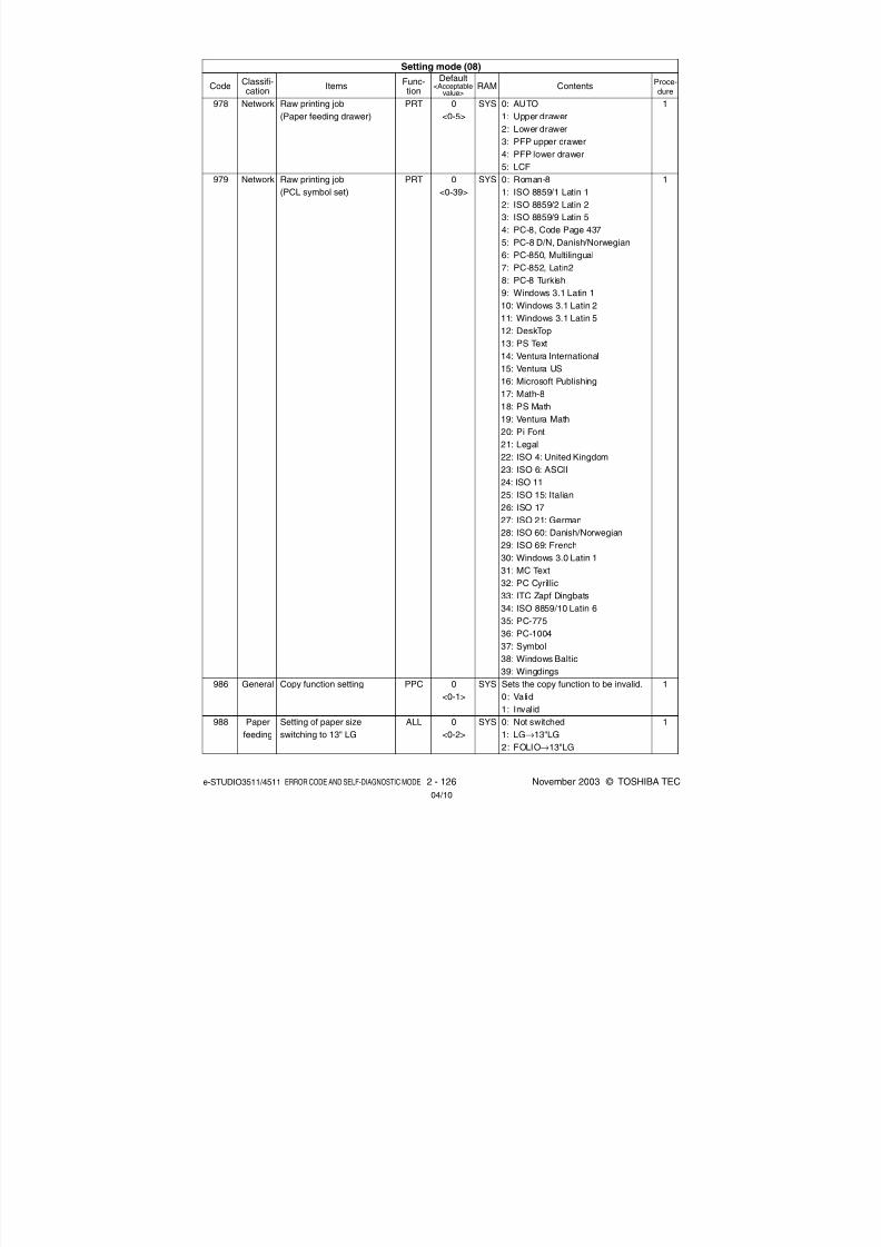
8/2/2019 ES-3511 Service Handbook
http://slidepdf.com/reader/full/es-3511-service-handbook 146/543
e-STUDIO3511/4511 ERROR CODE AND SELF-DIAGNOSTIC MODE 2 - 126 November 2003 © TOSHIBA TEC
978
979
986
988
Network
Network
General
Paper
feeding
PRT
PRT
PPC
ALL
Raw printing job
(Paper feeding drawer)
Raw printing job
(PCL symbol set)
Copy function setting
Setting of paper size
switching to 13" LG
0
<0-5>
0
<0-39>
0
<0-1>
0
<0-2>
SYS
SYS
SYS
SYS
0: AUTO
1: Upper drawer
2: Lower drawer
3: PFP upper drawer
4: PFP lower drawer5: LCF
0: Roman-8
1: ISO 8859/1 Latin 1
2: ISO 8859/2 Latin 2
3: ISO 8859/9 Latin 5
4: PC-8, Code Page 437
5: PC-8 D/N, Danish/Norwegian
6: PC-850, Multilingual
7: PC-852, Latin2
8: PC-8 Turkish
9: Windows 3.1 Latin 1
10: Windows 3.1 Latin 2
11: Windows 3.1 Latin 5
12: DeskTop
13: PS Text
14: Ventura International
15: Ventura US
16: Microsoft Publishing
17: Math-8
18: PS Math
19: Ventura Math
20: Pi Font
21: Legal
22: ISO 4: United Kingdom
23: ISO 6: ASCII24: ISO 11
25: ISO 15: Italian
26: ISO 17
27: ISO 21: German
28: ISO 60: Danish/Norwegian
29: ISO 69: French
30: Windows 3.0 Latin 1
31: MC Text
32: PC Cyrillic
33: ITC Zapf Dingbats
34: ISO 8859/10 Latin 6
35: PC-77536: PC-1004
37: Symbol
38: Windows Baltic
39: Wingdings
Sets the copy function to be invalid.
0: Valid
1: Invalid
0: Not switched
1: LG→13"LG
2: FOLIO→13"LG
1
1
1
1
Setting mode (08)
CodeClassifi-cation
ItemsFunc-tion
Default<Acceptable
value>RAM Contents
Proce-
dure
04/10

8/2/2019 ES-3511 Service Handbook
http://slidepdf.com/reader/full/es-3511-service-handbook 147/543
November 2003 © TOSHIBA TEC 2 - 127 e-STUDIO3511/4511 ERROR CODE AND SELF-DIAGNOSTIC MODE
-
0
<10 digits>
0
<8 digits>
3
<1-3>
1
<1-2>
3
<1-3>
-
1
<1-2>
2
<1-3>
-
-
-
-
1
<1-2>
1
<1-5>
1
<1-2>
1
<1-2>
∗
1
<1-2>
1
<1-2>
-
-
Performs the initial setting of the
scrambler board.
This code can be also keyed in from
the adjustment mode (05-976).10 digits
Refer to values of total counter.
1: Cold 2: Warm 3: Not reset
1: Not printed out when the copier is
restarted
2: Printed out when the copier is
restarted
1: 10 MBPS 2: 100 MBPS
3: Automatic
Writing only (Current setting is not
displayed.)
Maximum 31 letters
1: Available 2: Not available
1: Unchanging
2: Automatic addressing (DHCP)
3: No IP address applied to auto-
matic addressing (DHCP)
Maximum 96 letters
000.000.000.000-255.255.255.255
(Default value 000.000.000.000)
000.000.000.000-255.255.255.255
(Default value 000.000.000.000)
000.000.000.000-255.255.255.255
(Default value 000.000.000.000)
1: Available 2: Not available
1: Automatic 2: IEEE802.3
3: Ethernet II 4: IEEE802.3 SNAP
5: IEEE802.2
1: Available 2: Not available
1: Available 2: Not available
Maximum 32 letters*: Wildcard character
1: Available 2: Not available
1: Available 2: Not available
000.000.000.000-255.255.255.255
(Default value 000.000.000.000)
000.000.000.000-255.255.255.255
(Default value 000.000.000.000)
3
11
1
12
12
12
12
12
12
12
12
12
12
12
12
12
12
12
12
12
12
12
-
SYS
SYS
NIC
NIC
NIC
NIC
NIC
NIC
NIC
NIC
NIC
NIC
NIC
NIC
NIC
NIC
NIC
NIC
NIC
NIC
NIC
989
995
999
1001
1002
1003
1004
1005
1006
1007
1008
1009
1010
1011
1012
1013
1014
1015
1016
1017
1018
1019
Scram-
bler
board
Mainte-
nance
Mainte-
nance
Network
Network
Network
Network
Network
Network
Network
Network
Network
Network
Network
Network
Network
Network
Network
Network
Network
Network
Network
Scrambler board initial
setting
Equipment number (serial
number) display
FSMS total counter
Reset of NIC board
Selection of NIC board
status information
Speed setting of Ethernet
NIC Web password
Availability of IP
Method of IP addressing
Domain name
IP address
Subnet mask
Gateway
Availability of IPX
Network frame type
Availability of NCP Burst
Availability of AppleTalk
Zone setting of AppleTalk
Availability of LDAP
Availability of DNS
IP address to DNS server
(Primary)
IP address to DNS server
(Secondary)
ALL
ALL
ALL
ALL
ALL
ALL
ALL
ALL
ALL
ALL
ALL
ALL
ALL
ALL
ALL
ALL
ALL
ALL
ALL
ALL
ALL
ALL
Adjustment mode (08)
CodeClassifi-cation
ItemsFunc-tion
Default<Acceptable
value>RAM Contents
Proce-dure
04/05

8/2/2019 ES-3511 Service Handbook
http://slidepdf.com/reader/full/es-3511-service-handbook 148/543
e-STUDIO3511/4511 ERROR CODE AND SELF-DIAGNOSTIC MODE 2 - 128 November 2003 © TOSHIBA TEC
1: Invalid 2: Via DHCP
3: Insecure DDNS 4: Secure DDNS
5: Multi-secure DDNS
1: Available 2: Not available
Maximum 15 letters
Maximum 128 letters
Maximum 128 letters
1: Available 2: Not available
1: Available 2: Not available
Maximum 127 letters
Maximum 47 letters
1: Available 2: Not available
1: Available 2: Not available
000.000.000.000-255.255.255.255
(Default value 000.000.000.000)
1: Available 2: Not available
Maximum 128 Bytes
1: Available 2: Not available
Maximum 192 letters
1: Available 2: Not available
1: Available 2: Not available
1: Available 2: Not available
1: Available 2: Not available
Maximum 128 Bytes
1: Automatic 2: POP3
3: APOP
12
12
12
12
12
12
12
12
12
12
12
1
12
12
12
12
12
12
12
12
12
12
12
12
12
12
12
1
<1-5>
1
<1-2>-
-
-
1
<1-2>
1
<1-2>
-
-
1
<1-2>
80
<1-65535>
8080
<1-65535>
1
<1-2>
80
<1-65535>
-
1
<1-2>
-
25
<1-65535>
1
<1-2>
25
<1-65535>
-
2
<1-2>1
<1-2>
1
<1-2>
1
<1-2>
-
1
<1-3>
NIC
NIC
NIC
NIC
NIC
NIC
NIC
NIC
NIC
NIC
NIC
SYS
NIC
NIC
NIC
NIC
NIC
NIC
NIC
NIC
NIC
NIC
NIC
NIC
NIC
NIC
NIC
1020
1021
1023
1024
1025
1026
1027
1028
1029
1030
1031
1032
1033
1034
1035
1037
1038
1039
1040
1041
1042
1043
1044
1045
1046
1047
1048
Network
Network
Network
Network
Network
Network
Network
Network
Network
Network
Network
Network
Network
Network
Network
Network
Network
Network
Network
Network
Network
Network
Network
Network
Network
Network
Network
DDNS Desired level
Availability of SLP
NetBios name
Name of WINS server or IP
address (Primary)
Name of WINS server or IP
address (Secondary)
Availability of Bindery
Availability of NDS
Directory service context
Directory service tree
Availability of HTTP server
Port number to NIC HTTP
server
Port number to system
HTTP server
Availability of NIC HTTP
client
TCP port number to Control-
ler HTTP client
IP address to HTTP server
(Primary)
Availability of SMTP client
FQDN or IP address to
SMTP server
TCP port number of SMTP
client
Availability of SMTP server
TCP port number of SMTP
server
E-mail box name to SMTP
server
Availability of Offramp
Offramp security
Printing at Offramp
Availability of POP3 clients
FQDN or IP address to
POP3 server
Types of POP3 server
ALL
ALL
ALL
ALL
ALL
ALL
ALL
ALL
ALL
ALL
ALL
ALL
ALL
ALL
ALL
ALL
ALL
ALL
ALL
ALL
ALL
ALL
ALL
ALL
ALL
ALL
ALL
Adjustment mode (08)
CodeClassifi-cation
ItemsFunc-tion
Default<Acceptable
value>RAM Contents
Proce-dure
04/05

8/2/2019 ES-3511 Service Handbook
http://slidepdf.com/reader/full/es-3511-service-handbook 149/543
November 2003 © TOSHIBA TEC 2 - 129 e-STUDIO3511/4511 ERROR CODE AND SELF-DIAGNOSTIC MODE
ALL
ALL
ALL
ALL
ALL
ALL
ALL
ALL
ALL
ALL
ALL
ALL
ALL
ALL
ALL
ALL
ALL
ALL
ALL
ALL
ALL
ALL
ALL
ALL
ALL
ALL
ALL
ALL
ALL
1049
1050
1051
1052
1053
1054
1055
1056
1057
1058
1059
1060
1061
1062
1063
1065
1066
1067
1068
1069
1070
1073
1074
1075
1076
1077
1078
1079
1080
Login name to POP3 server
Login password to POP3
E-mail reception interval
TCP port number of POP3client
Availability of FTP client
FQDN or IP address to FTP
server
TCP port number of FTP
client
Data port number of FTP
client
Login name to FTP server
Login password to FTP
server
Availability of FTP server
TCP port number of FTP
server
Login name to FTP client
Login password to FTP
client
MIB function
Setting of read Community
Setting of read/Write
Community
Authentication TRAP
function
ALERTS TRAP function
TRAP destination IP
address
Community setting of TRAP
(via IP)
Availability of Raw/TCP
TCP port number of Raw
Availability of LPD client
TCP port number of LPD
LPD queue name
Availability of IPP
Availability of IPP port
number “80”
TCP port number of IPP
Maximum 96 letters
Maximum 96 letters
Unit: Minute
1: Available 2: Not available
Maximum 128 letters
Maximum 31 letters
Maximum 31 letters
1: Available 2: Not available
Maximum 31 letters
Maximum 31 letters
1: Valid 2: Invalid
Maximum 31 letters
Maximum 31 letters
1: Valid 2: Invalid
1: Valid 2: Invalid
000.000.000.000-255.255.255.255
(Default value 000.000.000.000)
Maximum 31 letters
1: Valid 2: Invalid
1: Valid 2: Invalid
Maximum 31 letters
1: Valid 2: Invalid
1: Valid 2: Invalid
Network
Network
Network
Network
Network
Network
Network
Network
Network
Network
Network
Network
Network
Network
Network
Network
Network
Network
Network
Network
Network
Network
Network
Network
Network
Network
Network
Network
Network
-
-
5
<0-4096>
110<1-65535>
1
<1-2>
-
21
<1-65535>
0
<0-65535>
-
-
1
<1-2>
21
<1-65535>
-
-
1
<1-2>
public
private
1
<1-2>
1
<1-2>
-
public
1
<1-2>
9100
<1-65535>
1<1-2>
515
<1-65535>
-
1
<1-2>
1
<1-2>
631
<1-65535>
NIC
NIC
NIC
NIC
NIC
NIC
NIC
NIC
SYS
SYS
NIC
NIC
SYS
SYS
NIC
NIC
NIC
NIC
NIC
NIC
NIC
NIC
NIC
NIC
NIC
NIC
NIC
NIC
NIC
12
12
12
12
12
12
12
12
11
11
12
12
11
11
12
12
12
12
12
12
12
12
12
12
12
12
12
12
12
Adjustment mode (08)
CodeClassifi-cation
ItemsFunc-tion
Default<Acceptable
value>RAM Contents
Proce-dure

8/2/2019 ES-3511 Service Handbook
http://slidepdf.com/reader/full/es-3511-service-handbook 150/543
e-STUDIO3511/4511 ERROR CODE AND SELF-DIAGNOSTIC MODE 2 - 130 November 2003 © TOSHIBA TEC
IPP printer name
IPP printer location
IPP printer information
IPP printer information
(more)Installer of IPP printer driver
IPP printer “Make and
Model”
IPP printer information (more)
MFGR
IPP message from operator
Availability of FTP print
Printer user name of FTP
Printer user password of
FTP
TCP port number to FTP
print server
Login name to Novell print
server
Login password to Novell
print server
Name of SearchRoot server
Scan rate setting of print
queue
Page number limitation for
printing text of received E-
MDN return mail setting
when receiving E-mail
Trap destination of IPX
Method of SMTP server
authentication
Login name for SMTP
server authentication
Login password for SMTP
server authentication
Rendezvous setting
Link local host name
Service name setting
FTP server setting
Maximum 127 letters
Maximum 127 letters
Maximum 127 letters
Maximum 127 letters
Maximum 127 letters
Maximum 127 letters
Maximum 127 letters
Maximum 127 letters
1: Available 2: Not available
Maximum 31 letters
Maximum 31 letters
Maximum 47 letters
Maximum 31 letters
Maximum 31 letters
Unit: Second
1: Valid 2: Invalid
Maximum 24 letters
(Valid from 0 to 9 and from A to F)
1: Plain
2: Login
3; Cram-MD5
4: Digest MD5
5: Disable
Maximum 64 letters
Maximum 64 letters
1: Valid 2: Invalid
Maximum 127 letters
Maximum 63 letters
<Default value>
e-STUDIO3511:
TOSHIBA e-STUDIO3511
e-STUDIO4511:
TOSHIBA e-STUDIO4511
1: Valid 2: Invalid
12
12
12
12
12
12
12
12
12
12
12
12
12
12
12
12
12
12
12
12
12
12
12
12
12
12
NIC
NIC
NIC
NIC
NIC
NIC
NIC
NIC
NIC
NIC
NIC
NIC
NIC
NIC
NIC
NIC
NIC
NIC
NIC
NIC
NIC
NIC
NIC
NIC
NIC
NIC
-
-
-
-
-
-
-
-
1
<1-2>
-
21
<1-65535>
-
-
-
5
<1-255>
5
<1-99>
2
<1-2>
-
5
<1-5>
-
-
1<1-2>
MFP_serial
Refer to
contents
1
<1-2>
ALL
ALL
ALL
ALL
ALL
ALL
ALL
ALL
ALL
ALL
ALL
ALL
ALL
ALL
ALL
ALL
ALL
ALL
ALL
ALL
ALL
ALL
ALL
ALL
ALL
ALL
1081
1082
1083
1084
1085
1086
1087
1088
1089
1090
1091
1092
1093
1094
1095
1096
1097
1098
1099
1100
1101
1102
1103
1104
1105
1106
Network
Network
Network
Network
Network
Network
Network
Network
Network
Network
Network
Network
Network
Network
Network
Network
Network
Network
Network
Network
Network
Network
Network
Network
Network
Network
Adjustment mode (08)
CodeClassifi-cation
ItemsFunc-tion
Default<Acceptable
value>RAM Contents
Proce-dure
04/10

8/2/2019 ES-3511 Service Handbook
http://slidepdf.com/reader/full/es-3511-service-handbook 151/543
November 2003 © TOSHIBA TEC 2 - 131 e-STUDIO3511/4511 ERROR CODE AND SELF-DIAGNOSTIC MODE
ALL
ALL
ALL
ALL
ALL
ALL
ALL
ALL
ALL
ALL
ALL
ALL
ALL
ALL
ALL
ALL
ALL
PRT
ALL
ALL
Tiger
Woods
Shigeki
Maruyama
2
<1-2>
MFP_serial
-
1
<0-1>
300
<1-9999>
0
<0-1>
-
-
4
<3-4>
workgroup
1
<0-1>
1000
<5-1000>
1
<0-1>
1
<1-5>
13
<0-16>
16
<8-20>
UTY
UTY
UTY
UTY
NIC
NIC
NIC
SYS
SYS
SYS
UTY
UTY
UTY
UTY
SYS
SYS
SYS
SYS
SYS
SYS
Maximum 64 letters
Maximum 32 letters
Maximum 64 letters
Maximum 32 letters
1: Valid 2: Invalid
Maximum 127 letters
Maximum 96 letters
0: Inval id 1: Valid
Unit: Second
0: Read (Reads all of the setting
information in NIC and create a file
NAM1B (no extension) in USB)
1: Write (Writes all of the setting
information read from a file
NAM1B (no extension) in USB)
Maximum 15 letters
Maximum 15 letters
3: ON (Domain selected)
4: OFF (Work group selected)
Maximum 15 letters
Sets the Job Build Function.
0: Invalid
1: Valid
Sets the maximum number of time a
job build has been performed.
5-1000: 5 to 1000 times
Selects the default screen when
entering the User Function menu by
pressing the [USER FUNCTIONS]
button.
0: ADDRESS 1: COUNTER
1: LCF
2: Upper drawer3: Lower drawer
4: PFP upper drawer
5: PFP lower drawer
8-20 M bytes
1107
1108
1109
1110
1111
1112
1113
1114
1117
1120
1121
1122
1123
1124
1130
1131
1132
1135
1136
1137
FTP server login name 1
FTP server login password 1
FTP server login name 2
FTP server login password 2
POP Before SMTP setting
Host name
NT domain name
Sending mail text of
InternetFAX
SMB time-out period
Backup/Restore of NIC
setting information
PDC (Primary Domain
Controller) name
BDC (Backup Domain
Controller) name
NT domain ON/OFF setting
Workgroup name
Job Build Function
Maximum number of time
job build performed
Default screen selection of
the User Function menu
Default setting of drawers
(Printer/BOX)
Number of lines simulta-
neously connectable when
using SMB
Memory partition size when
using Samba
Network
Network
Network
Network
Network
Network
Network
Network
Network
Network
Network
Network
Network
Network
User
interface
User
interface
General
Paper
feeding
Network
Network
12
12
12
12
12
12
12
1
1
1
12
12
12
12
1
1
1
1
1
1
Adjustment mode (08)
CodeClassifi-cation
ItemsFunc-tion
Default<Acceptable
value>RAM Contents
Proce-dure
04/10

8/2/2019 ES-3511 Service Handbook
http://slidepdf.com/reader/full/es-3511-service-handbook 152/543
e-STUDIO3511/4511 ERROR CODE AND SELF-DIAGNOSTIC MODE 2 - 132 November 2003 © TOSHIBA TEC
1138
1139
1140
1370
1371
1372
1378
1380
1382
1385
Network
Network
User
interface
Image
process-
ing
Image
process-
ing
Image
process-
ing
Image
process-
ing
Image
process-
ing
Image
process-
ing
Image
process-
ing
LDAP search method setting
LDAP authentication setting
Restriction of the template
function with the administra-
tor privilege
Image quality control time
accumulating counter
Accumulated counter of
output pages since the
performing of image quality
control
Heater and energizing time
accumulating counter
Display/0 clearing
Fuser roller ready
temperature time
accumulating counter
Fuser roller printing
temperature time
accumulating counter
Fuser roller energy saving
temperature time
accumulating counter
Display/0 clearing
Number of output pages
(Thick paper 1)
ALL
ALL
ALL
ALL
ALL
ALL
ALL
ALL
ALL
ALL
0
<0-3>
0
<0-1>
0
<0-1>
0
<8 digits>
0
<4 digits>
0
<8 digits>
0
<8 digits>
0
<8 digits>
0
<8 digits>
0
<8 digits>
Sets the search method when
performing a LDAP search.
0: Partial match
1: Prefix match
2: Suffix match3: Full match
0: Not authenticated
1: Authenticated
Selects the restriction of the template
function usage setting.
0: No restriction
1: Only available with the administra-
tor privilege.
Counts driving count of the drum
(image quality control time).
Counts up when drum motor and
image quality control are ON.
Cleared to “0” by the image quality
closed-loop control. Counts up with
the number of printing job received
after this control.
Counts up the heater control time
accumulated (when power of the copier
is ON) but does not count at the Sleep
Mode. When the counter value of the
fuser belt is cleared, this counter value
is also cleared in sync at PM support
mode.
Counts up the heater control time
accumulated (on standby). When the
counter value of the fuser belt is
cleared, this counter value is also
cleared in sync at PM support mode.
Counts up the heater control time
accumulated (during printing). When
the counter value of the fuser belt is
cleared, this counter value is also
cleared in sync at PM support mode.
Counts up the heater control time
accumulated (at energy saving
mode). When the counter value of
the fuser belt is cleared, this countervalue is also cleared in sync at PM
support mode.
Counts up when the registration
sensor is ON. When the counter
value of the fuser belt is cleared, this
counter value is also cleared in sync
at PM support mode.
SYS
SYS
SYS
M
M
M
M
M
M
M
1
1
1
1
2
1
2
2
2
1
Adjustment mode (08)
CodeClassifi-cation
ItemsFunc-tion
Default<Acceptable
value>RAM Contents
Proce-dure
04/09

8/2/2019 ES-3511 Service Handbook
http://slidepdf.com/reader/full/es-3511-service-handbook 153/543
November 2003 © TOSHIBA TEC 2 - 133 e-STUDIO3511/4511 ERROR CODE AND SELF-DIAGNOSTIC MODE
Counts up when the registration
sensor is ON. When the counter
value of the fuser belt is cleared, this
counter value is also cleared in sync
at PM support mode.Counts up when the registration
sensor is ON. When the counter
value of the fuser belt is cleared, this
counter value is also cleared in sync
at PM support mode.
Counts up when the registration
sensor is ON. When the counter
value of the fuser belt is cleared, this
counter value is also cleared in sync
at PM support mode.
Does not count up when cleaning is
not effective.
Counts the number of times of the
feeding retry from the upper drawer.
Counts the number of times of the
feeding retry from the lower drawer.
Counts the number of times of the
feeding retry from the PFP upper
drawer.
Counts the number of times of the
feeding retry from the PFP lower
drawer.
Counts the number of times of the
feeding retry from the bypass tray.
Counts the number of times of the
feeding retry from the LCF.
When the number of feeding retry
(08-1390 to 08-1395) exceeds the
setting value, the feeding retry will
not be performed subsequently. In
case “0” is set as a setting value,
however, the feeding retry continues
regardless of the counter setting
value.
Refer to (Note 1).
1
1
1
1
1
1
1
1
1
1
1
1
1
1
1
1
1
Number of output pages
(Thick paper 2)
Number of output pages
(Thick paper 3)
Number of output pages
(OHP film)
Main charger wire cleaning
counter display/0 clearing
Feeding retry counter
(upper drawer)
Feeding retry counter
(lower drawer)
Feeding retry counter
(PFP upper drawer)
Feeding retry counter
(PFP lower drawer)
Feeding retry counter
(bypass feed)
Feeding retry counter
(LCF)
Feeding retry counter upper
limit value
(upper drawer)
Feeding retry counter upper
limit value
(lower drawer)
Feeding retry counter upper
limit value
(PFP upper drawer)
Feeding retry counter upper
limit value(PFP lower drawer)
Feeding retry counter upper
limit value
(bypass feed)
Feeding retry counter upper
limit value (LCF)
Black toner cartridge drive
counts/0 clearing
ALL
ALL
ALL
ALL
ALL
ALL
ALL
ALL
ALL
ALL
ALL
ALL
ALL
ALL
ALL
ALL
ALL
0
<8 digits>
0
<8 digits>
0
<8 digits>
0
<5 digits>
0
<8 digits>
0
<8 digits>
0
<8 digits>
0
<8 digits>
0
<8 digits>
0
<8 digits>
10
<8 digits>
10
<8 digits>
10
<8 digits>
10
<8 digits>
10
<8 digits>
10
<8 digits>
<8 digits>
M
M
M
M
M
M
M
M
M
M
M
M
M
M
M
M
M
1386
1387
1388
1389
1390
1391
1392
1393
1394
1395
1396
1397
1398
1399
1400
1401
1410
Image
process-
ing
Image
process-
ing
Image
process-
ing
Main
charger
Paper
feeding
Paper
feeding
Paper
feeding
Paper
feeding
Paper
feeding
Paper
feeding
Paper
feeding
Paper
feeding
Paper
feeding
Paper
feeding
Paper
feeding
Paper
feeding
Counter
Adjustment mode (08)
CodeClassifi-cation
ItemsFunc-tion
Default<Acceptable
value>RAM Contents
Proce-dure
04/05

8/2/2019 ES-3511 Service Handbook
http://slidepdf.com/reader/full/es-3511-service-handbook 154/543
e-STUDIO3511/4511 ERROR CODE AND SELF-DIAGNOSTIC MODE 2 - 134 November 2003 © TOSHIBA TEC
1412
1414
1415
1416
1800-0
1800-1
1800-2
1801
1802-0
1802-1
1802-2
Counter
Image
process-
ing
Image
process-
ing
Image
process-
ing
Image
process-
ing
Image
process-
ing
Image
process-
ing
Counter for tab paper
Toner cartr idge wrong
installation detection ON/
OFF setting
Detection/control that the
toner cartridge is nearly
empty
Threshold for detecting that
black toner cartridge is
nearly empty
Color toner forced
supply time
setting
Color toner forced supply
count setting
Start up setting of
the developer
material stabiliz-
ing mode.
ALL
ALL
ALL
ALL
ALL
(color)
ALL
(color)
ALL
(color)
ALL
(color)
ALL
ALL
ALL
0
<8 digits>
0
<0-1>
1
<0-1>
<8 digits>
70
<0-255>
70
<0-255>
70
<0-255>
7
<1-10>
3
<2-8>
50
<0-100>
10
<0-20>
M
M
M
M
M
M
M
M
M
M
M
Y
M
C
Level
Pattern
interval
Number
of
repeating
time
Counts up when the registration
sensor is ON.
When the counter value of the fuser
roller is reset, this counter is reset in
sync at the PM support mode.0: ON
1: OFF
Sets ON or OFF of the detection/
control that the toner cartridge is
nearly empty.
0: OFF 1: ON
Sets the motor driving time of the
developer unit at the time of the color
toner forced supply.
0-255: Setting value x 0.1 seconds
Sets the number of times of the color
toner forced supply.
Sets the performing level of the
developer material stabilizing
operation.
Set the interval time between
performances of developer material
stabilizing operation.
Set the number of repeating times of
the developer material stabilizing
operation.
1
1
1
1
4
4
4
1
4
4
4
(Note 1)
In this equipment, a toner image is formed on the transfer belt prior to a paper feeding.
When the feeding retry occurs and the transport timing is delayed, the toner image on the transfer belt is
cleaned off without the 2nd transfer since the paper cannot be reached for the 2nd transfer process.
After that, the toner image formation is retried while the paper is waited.
In this case, the toner for this image formation is consumed wastefully since the toner image on the
transfer belt is already cleaned off, even though the printing is normally completed.
Therefore, note that the excessive toner will be consumed consequently when the upper limit value of
feeding retry counter is set larger or set as “0” (no limit).
The toner is also consumed wastefully when the paper misfeeding occurs. Replace the roller at earlier
timing if the paper misfeedings have occurred frequently.
Adjustment mode (08)
CodeClassifi-cation
ItemsFunc-tion
Default<Acceptable
value>RAM Contents
Proce-dure
04/10

8/2/2019 ES-3511 Service Handbook
http://slidepdf.com/reader/full/es-3511-service-handbook 155/543
November 2003 © TOSHIBA TEC 2 - 135 e-STUDIO3511/4511 ERROR CODE AND SELF-DIAGNOSTIC MODE
Standard paper size setting
Pixel counter all clearing
Service technician reference
counter clearing
Toner cartridge reference
counter clearing
Pixel counter display setting
Displayed reference setting
Toner empty determination
counter setting
Threshold setting for toner
empty determination (Output
pages)
Threshold setting for toner
empty determination (Pixel
counter)
Pixel counter clear flag/
Service technician reference
Service technician reference
cleared date
Toner cartridge reference
cleared date (Y)
Toner cartridge reference
cleared date (M)Toner cartridge reference
cleared date (C)
Toner cartridge reference
cleared date (K)
Toner cartridge reference
count started date (Y)
Toner cartridge reference
count started date (M)
Toner cartridge reference
count started date (C)
ALL
ALL
ALL
ALL
ALL
ALL
ALL
ALL
ALL
ALL
ALL
ALL
(color)
ALL
(color)ALL
(color)
ALL
ALL
(color)
ALL
(color)
ALL
(color)
EUR: 0UC: 1
JPN: 0
<0-1>
-
-
-
1
<0-1>
0
<0-1>
0
<0-1>
500
<0-999>
21500
<0-60000>
0
<0-1>
-
-
-
-
-
-
-
-
SYS
SYS
SYS
SYS
SYS
SYS
SYS
SYS
SYS
SYS
SYS
SYS
SYS
SYS
SYS
SYS
SYS
SYS
Selects the standard paper size toconvert it into the pixel count (%).
0: A4 1: LT
Clears all information related to the
pixel counter.
Clears all information related to the
service technician reference pixel
counter.
Clears all information related to the
toner cartridge reference pixel
counter.
Selects whether or not to display the
pixel counter on the LCD screen.
0: Displayed 1: Not displayed
Selects the reference when display-
ing the pixel counter on the LCD
screen.
0: Service technician reference
1: Toner cartridge reference
Selects the counter to determine
toner empty.
0: Output pages 1: Pixel counter
Sets the number of output pages to
determine toner empty. This setting is
valid when “0” is set at 08-1506.
Sets the number of output pages to
determine toner empty. This setting is
valid when “1” is set at 08-1506.
Becomes “1” when 08-1502 is
performed.
Displays the date on which 08-1502
was performed.
Displays the date on which 08-1503
was performed.
Displays the date on which 08-1503
was performed.Displays the date on which 08-1503
was performed.
Displays the date on which 08-1503
was performed.
Displays the date on which 08-1503
was performed.
Displays the date on which 08-1503
was performed.
Displays the date on which 08-1503
was performed.
1500
1501
1502
1503
1504
1505
1506
1507
1508
1509
1510
1511
1512
1513
1514
1515
1516
1517
Pixelcounter
Pixel
counter
Pixel
counter
Pixel
counter
Pixel
counter
Pixel
counter
Pixel
counter
Pixel
counter
Pixel
counter
Pixel
counter
Pixel
counter
Pixel
counter
Pixel
counterPixel
counter
Pixel
counter
Pixel
counter
Pixel
counter
Pixel
counter
<<Pixel counter related code>> ( Chapter 2.2.6)
Note: In the pixel counter function, the twin color copy mode is regarded as the full color mode.
Setting mode (08)
CodeClassifi-cation
ItemsFunc-tion
Default<Acceptable
value>RAM Contents
Proce-dure
1
3
3
3
1
1
1
1
1
2
2
2
2
2
2
2
2
2
04/05
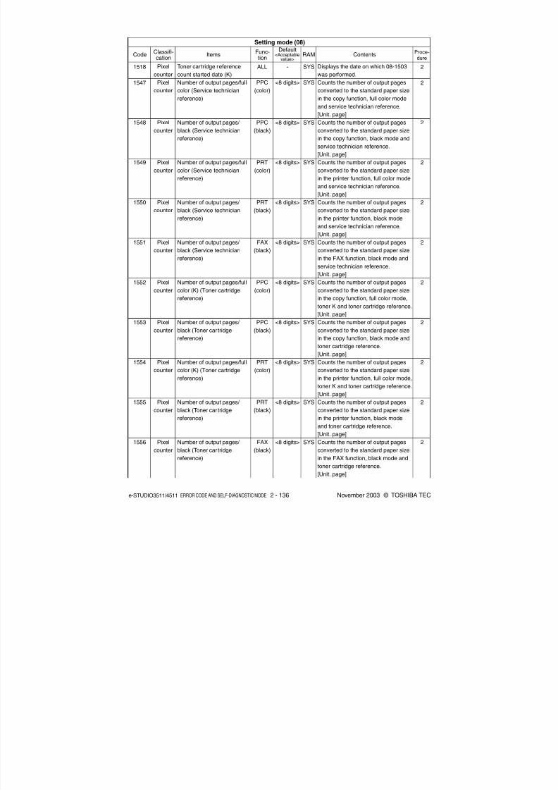
8/2/2019 ES-3511 Service Handbook
http://slidepdf.com/reader/full/es-3511-service-handbook 156/543
e-STUDIO3511/4511 ERROR CODE AND SELF-DIAGNOSTIC MODE 2 - 136 November 2003 © TOSHIBA TEC
Toner cartridge reference
count started date (K)
Number of output pages/full
color (Service technician
reference)
Number of output pages/
black (Service technician
reference)
Number of output pages/full
color (Service technician
reference)
Number of output pages/
black (Service technician
reference)
Number of output pages/
black (Service technician
reference)
Number of output pages/full
color (K) (Toner cartridge
reference)
Number of output pages/
black (Toner car tridge
reference)
Number of output pages/full
color (K) (Toner cartridge
reference)
Number of output pages/
black (Toner car tridge
reference)
Number of output pages/
black (Toner car tridge
reference)
1518
1547
1548
1549
1550
1551
1552
1553
1554
1555
1556
Pixel
counter
Pixel
counter
Pixel
counter
Pixel
counter
Pixel
counter
Pixel
counter
Pixel
counter
Pixel
counter
Pixel
counter
Pixel
counter
Pixel
counter
ALL
PPC
(color)
PPC
(black)
PRT
(color)
PRT
(black)
FAX
(black)
PPC
(color)
PPC
(black)
PRT
(color)
PRT
(black)
FAX
(black)
-
<8 digits>
<8 digits>
<8 digits>
<8 digits>
<8 digits>
<8 digits>
<8 digits>
<8 digits>
<8 digits>
<8 digits>
SYS
SYS
SYS
SYS
SYS
SYS
SYS
SYS
SYS
SYS
SYS
Displays the date on which 08-1503
was performed.
Counts the number of output pages
converted to the standard paper size
in the copy function, full color modeand service technician reference.
[Unit. page]
Counts the number of output pages
converted to the standard paper size
in the copy function, black mode and
service technician reference.
[Unit. page]
Counts the number of output pages
converted to the standard paper size
in the printer function, full color mode
and service technician reference.
[Unit. page]
Counts the number of output pages
converted to the standard paper size
in the printer function, black mode
and service technician reference.
[Unit. page]
Counts the number of output pages
converted to the standard paper size
in the FAX function, black mode and
service technician reference.
[Unit. page]
Counts the number of output pages
converted to the standard paper size
in the copy function, full color mode,
toner K and toner cartridge reference.
[Unit. page]
Counts the number of output pages
converted to the standard paper size
in the copy function, black mode and
toner cartridge reference.
[Unit. page]
Counts the number of output pages
converted to the standard paper size
in the printer function, full color mode,
toner K and toner cartridge reference.
[Unit. page]Counts the number of output pages
converted to the standard paper size
in the printer function, black mode
and toner cartridge reference.
[Unit. page]
Counts the number of output pages
converted to the standard paper size
in the FAX function, black mode and
toner cartridge reference.
[Unit. page]
Setting mode (08)
CodeClassifi-cation
ItemsFunc-tion
Default<Acceptable
value>RAM Contents
Proce-dure
2
2
2
2
2
2
2
2
2
2
2
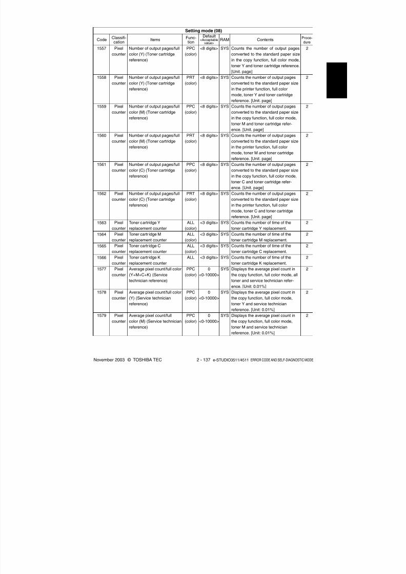
8/2/2019 ES-3511 Service Handbook
http://slidepdf.com/reader/full/es-3511-service-handbook 157/543
November 2003 © TOSHIBA TEC 2 - 137 e-STUDIO3511/4511 ERROR CODE AND SELF-DIAGNOSTIC MODE
1557
1558
1559
1560
1561
1562
1563
1564
1565
1566
1577
1578
1579
Pixel
counter
Pixel
counter
Pixel
counter
Pixel
counter
Pixel
counter
Pixel
counter
Pixel
counter
Pixel
counter
Pixel
counter
Pixel
counter
Pixel
counter
Pixel
counter
Pixel
counter
Number of output pages/full
color (Y) (Toner cartridge
reference)
Number of output pages/full
color (Y) (Toner cartridge
reference)
Number of output pages/full
color (M) (Toner cartridge
reference)
Number of output pages/full
color (M) (Toner cartridge
reference)
Number of output pages/full
color (C) (Toner cartridge
reference)
Number of output pages/full
color (C) (Toner cartridge
reference)
Toner cartridge Y
replacement counter
Toner cartr idge M
replacement counter
Toner cartr idge C
replacement counter
Toner cartr idge K
replacement counter
Average pixel count/full color
(Y+M+C+K) (Service
technician reference)
Average pixel count/full color
(Y) (Service technician
reference)
Average pixel count/full
color (M) (Service technician
reference)
PPC
(color)
PRT
(color)
PPC
(color)
PRT
(color)
PPC
(color)
PRT
(color)
ALL
(color)
ALL
(color)
ALL
(color)
ALL
PPC
(color)
PPC
(color)
PPC
(color)
<8 digits>
<8 digits>
<8 digits>
<8 digits>
<8 digits>
<8 digits>
<3 digits>
<3 digits>
<3 digits>
<3 digits>
0
<0-10000>
0
<0-10000>
0
<0-10000>
SYS
SYS
SYS
SYS
SYS
SYS
SYS
SYS
SYS
SYS
SYS
SYS
SYS
Counts the number of output pages
converted to the standard paper size
in the copy function, full color mode,
toner Y and toner cartridge reference.
[Unit. page]Counts the number of output pages
converted to the standard paper size
in the printer function, full color
mode, toner Y and toner cartridge
reference. [Unit. page]
Counts the number of output pages
converted to the standard paper size
in the copy function, full color mode,
toner M and toner cartridge refer-
ence. [Unit. page]
Counts the number of output pages
converted to the standard paper size
in the printer function, full color
mode, toner M and toner cartridge
reference. [Unit. page]
Counts the number of output pages
converted to the standard paper size
in the copy function, full color mode,
toner C and toner cartridge refer-
ence. [Unit. page]
Counts the number of output pages
converted to the standard paper size
in the printer function, full color
mode, toner C and toner cartridge
reference. [Unit. page]
Counts the number of time of the
toner cartridge Y replacement.
Counts the number of time of the
toner cartridge M replacement.
Counts the number of time of the
toner cartridge C replacement.
Counts the number of time of the
toner cartridge K replacement.
Displays the average pixel count in
the copy function, full color mode, all
toner and service technician refer-
ence. [Unit: 0.01%]Displays the average pixel count in
the copy function, full color mode,
toner Y and service technician
reference. [Unit: 0.01%]
Displays the average pixel count in
the copy function, full color mode,
toner M and service technician
reference. [Unit: 0.01%]
2
2
2
2
2
2
2
2
2
2
2
2
2
Setting mode (08)
CodeClassifi-cation
ItemsFunc-tion
Default<Acceptable
value>RAM Contents
Proce-dure

8/2/2019 ES-3511 Service Handbook
http://slidepdf.com/reader/full/es-3511-service-handbook 158/543
e-STUDIO3511/4511 ERROR CODE AND SELF-DIAGNOSTIC MODE 2 - 138 November 2003 © TOSHIBA TEC
0
<0-10000>
0<0-10000>
0
<0-10000>
0
<0-10000>
0
<0-10000>
0
<0-10000>
0
<0-10000>
0
<0-10000>
0
<0-10000>
0
<0-10000>
0
<0-10000>
0
<0-10000>
0
<0-10000>
SYS
SYS
SYS
SYS
SYS
SYS
SYS
SYS
SYS
SYS
SYS
SYS
SYS
Displays the average pixel count in
the copy function, full color mode,
toner C and service technician
reference. [Unit: 0.01%]
Displays the average pixel count inthe copy function, full color mode,
toner K and service technician
reference. [Unit: 0.01%]
Displays the average pixel count in
the printer function, full color mode,
all toner and service technician
reference. [Unit: 0.01%]
Displays the average pixel count in
the printer function, full color mode,
toner Y and service technician
reference. [Unit: 0.01%]
Displays the average pixel count in
the printer function, full color mode,
toner M and service technician
reference. [Unit: 0.01%]
Displays the average pixel count in
the printer function, full color mode,
toner C and service technician
reference. [Unit: 0.01%]
Displays the average pixel count in
the printer function, full color mode,
toner K and service technician
reference. [Unit: 0.01%]
Displays the average pixel count in
the copy/printer function, full color
mode, all toner and service techni-
cian reference. [Unit: 0.01%]
Displays the average pixel count in
the copy/printer function, full color
mode, toner Y and service technician
reference. [Unit: 0.01%]
Displays the average pixel count in
the copy/printer function, full color
mode, toner M and service techni-
cian reference. [Unit: 0.01%]
Displays the average pixel count in
the copy/printer function, full colormode, toner C and service technician
reference. [Unit: 0.01%]
Displays the average pixel count in
the copy/printer function, full color
mode, toner K and service technician
reference. [Unit: 0.01%]
Displays the average pixel count in
the copy function, black mode and
service technician reference.
[Unit: 0.01%]
Average pixel count/full color
(C) (Service technician
reference)
Average pixel count/full color(K) (Service technician
reference)
Average pixel count/full color
(Y+M+C+K) (Service
technician reference)
Average pixel count/full color
(Y) (Service technician
reference)
Average pixel count/full color
(M) (Service technician
reference)
Average pixel count/full color
(C) (Service technician
reference)
Average pixel count/full color
(K) (Service technician
reference)
Average pixel count/full color
(Y+M+C+K) (Service
technician reference)
Average pixel count/full color
(Y) (Service technician
reference)
Average pixel count/full color
(M) (Service technician
reference)
Average pixel count/full color
(C) (Service technicianreference)
Average pixel count/full color
(K) (Service technician
reference)
Average pixel count/black
(Service technician refer-
ence)
PPC
(color)
PPC(color)
PRT
(color)
PRT
(color)
PRT
(color)
PRT
(color)
PRT
(color)
PPC/
PRT
(color)
PPC/
PRT
(color)
PPC/
PRT
(color)
PPC/
PRT(color)
PPC/
PRT
(color)
PPC
(black)
Setting mode (08)
CodeClassifi-cation
ItemsFunc-tion
Default<Acceptable
value>RAM Contents
Proce-dure
1580
1581
1582
1583
1584
1585
1586
1587
1588
1589
1590
1591
1592
Pixel
counter
Pixelcounter
Pixel
counter
Pixel
counter
Pixel
counter
Pixel
counter
Pixel
counter
Pixel
counter
Pixel
counter
Pixel
counter
Pixel
counter
Pixel
counter
Pixel
counter
2
2
2
2
2
2
2
2
2
2
2
2
2

8/2/2019 ES-3511 Service Handbook
http://slidepdf.com/reader/full/es-3511-service-handbook 159/543
November 2003 © TOSHIBA TEC 2 - 139 e-STUDIO3511/4511 ERROR CODE AND SELF-DIAGNOSTIC MODE
Average pixel count/black
(Service technician refer-
ence)
Average pixel count/black(Service technician refer-
ence)
Average pixel count/black
(Service technician refer-
ence)
Latest pixel count/full color
(Y+M+C+K) (Service
technician reference)
Latest pixel count/full color
(Y) (Service technician
reference)
Latest pixel count/full color
(M) (Service technician
reference)
Latest pixel count/full color
(C) (Service technician
reference)
Latest pixel count/full color
(K) (Service technician
reference)
Latest pixel count/full color
(Y+M+C+K) (Service
technician reference)
Latest pixel count/full color
(Y) (Service technician
reference)
Latest pixel count/full color
(M) (Service technicianreference)
Latest pixel count/full color
(C) (Service technician
reference)
Latest pixel count/full color
(K) (Service technician
reference)
PRT
(black)
FAX(black)
PPC/
PRT/
FAX
(black)
PPC
(color)
PPC
(color)
PPC
(color)
PPC
(color)
PPC
(color)
PRT
(color)
PRT
(color)
PRT
(color)
PRT
(color)
PRT
(color)
Setting mode (08)
CodeClassifi-cation
ItemsFunc-tion
Default<Acceptable
value>RAM Contents
Proce-dure
1593
1594
1595
1596
1597
1598
1599
1600
1601
1602
1603
1604
1605
Pixel
counter
Pixelcounter
Pixel
counter
Pixel
counter
Pixel
counter
Pixel
counter
Pixel
counter
Pixel
counter
Pixel
counter
Pixel
counter
Pixel
counter
Pixel
counter
Pixel
counter
0
<0-10000>
0<0-10000>
0
<0-10000>
0
<0-10000>
0
<0-10000>
0
<0-10000>
0
<0-10000>
0
<0-10000>
0
<0-10000>
0
<0-10000>
0
<0-10000>
0
<0-10000>
0
<0-10000>
SYS
SYS
SYS
SYS
SYS
SYS
SYS
SYS
SYS
SYS
SYS
SYS
SYS
Displays the average pixel count in
the printer function, black mode and
service technician reference.
[Unit: 0.01%]
Displays the average pixel count inthe FAX function, black mode and
service technician reference.
[Unit: 0.01%]
Displays the average pixel count in
the copy/printer/FAX function, black
mode and service technician
reference. [Unit: 0.01%]
Displays the latest pixel count in the
copy function, full color mode, all
toner and service technician refer-
ence. [Unit: 0.01%]
Displays the latest pixel count in the
copy function, full color mode, toner
Y and service technician reference.
[Unit: 0.01%]
Displays the latest pixel count in the
copy function, full color mode, toner
M and service technician reference.
[Unit: 0.01%]
Displays the latest pixel count in the
copy function, full color mode, toner
C and service technician reference.
[Unit: 0.01%]
Displays the latest pixel count in the
copy function, full color mode, toner
K and service technician reference.
[Unit: 0.01%]
Displays the latest pixel count in the
printer function, full color mode, all
toner and service technician refer-
ence. [Unit: 0.01%]
Displays the latest pixel count in the
printer function, full color mode, toner
Y and service technician reference.
[Unit: 0.01%]
Displays the latest pixel count in the
printer function, full color mode, tonerM and service technician reference.
[Unit: 0.01%]
Displays the latest pixel count in the
printer function, full color mode, toner
C and service technician reference.
[Unit: 0.01%]
Displays the latest pixel count in the
printer function, full color mode, toner
K and service technician reference.
[Unit: 0.01%]
2
2
2
2
2
2
2
2
2
2
2
2
2
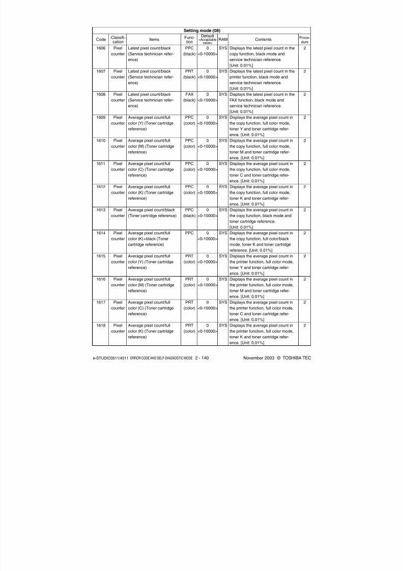
8/2/2019 ES-3511 Service Handbook
http://slidepdf.com/reader/full/es-3511-service-handbook 160/543
e-STUDIO3511/4511 ERROR CODE AND SELF-DIAGNOSTIC MODE 2 - 140 November 2003 © TOSHIBA TEC
Latest pixel count/black
(Service technician refer-
ence)
Latest pixel count/black(Service technician refer-
ence)
Latest pixel count/black
(Service technician refer-
ence)
Average pixel count/full
color (Y) (Toner cartridge
reference)
Average pixel count/full
color (M) (Toner cartridge
reference)
Average pixel count/full
color (C) (Toner cartridge
reference)
Average pixel count/full
color (K) (Toner cartridge
reference)
Average pixel count/black
(Toner cartr idge reference)
Average pixel count/full
color (K)+black (Toner
cartridge reference)
Average pixel count/full
color (Y) (Toner cartridge
reference)
Average pixel count/full
color (M) (Toner cartridgereference)
Average pixel count/full
color (C) (Toner cartridge
reference)
Average pixel count/full
color (K) (Toner cartridge
reference)
PPC
(black)
PRT(black)
FAX
(black)
PPC
(color)
PPC
(color)
PPC
(color)
PPC
(color)
PPC
(black)
PPC
PRT
(color)
PRT
(color)
PRT
(color)
PRT
(color)
Setting mode (08)
CodeClassifi-cation
ItemsFunc-tion
Default<Acceptable
value>RAM Contents
Proce-dure
1606
1607
1608
1609
1610
1611
1612
1613
1614
1615
1616
1617
1618
Pixel
counter
Pixelcounter
Pixel
counter
Pixel
counter
Pixel
counter
Pixel
counter
Pixel
counter
Pixel
counter
Pixel
counter
Pixel
counter
Pixel
counter
Pixel
counter
Pixel
counter
0
<0-10000>
0<0-10000>
0
<0-10000>
0
<0-10000>
0
<0-10000>
0
<0-10000>
0
<0-10000>
0
<0-10000>
0
<0-10000>
0
<0-10000>
0
<0-10000>
0
<0-10000>
0
<0-10000>
SYS
SYS
SYS
SYS
SYS
SYS
SYS
SYS
SYS
SYS
SYS
SYS
SYS
Displays the latest pixel count in the
copy function, black mode and
service technician reference.
[Unit: 0.01%]
Displays the latest pixel count in theprinter function, black mode and
service technician reference.
[Unit: 0.01%]
Displays the latest pixel count in the
FAX function, black mode and
service technician reference.
[Unit: 0.01%]
Displays the average pixel count in
the copy function, full color mode,
toner Y and toner cartridge refer-
ence. [Unit: 0.01%]
Displays the average pixel count in
the copy function, full color mode,
toner M and toner cartridge refer-
ence. [Unit: 0.01%]
Displays the average pixel count in
the copy function, full color mode,
toner C and toner cartridge refer-
ence. [Unit: 0.01%]
Displays the average pixel count in
the copy function, full color mode,
toner K and toner cartridge refer-
ence. [Unit: 0.01%]
Displays the average pixel count in
the copy function, black mode and
toner cartridge reference.
[Unit: 0.01%]
Displays the average pixel count in
the copy function, full color/black
mode, toner K and toner cartridge
reference. [Unit: 0.01%]
Displays the average pixel count in
the printer function, full color mode,
toner Y and toner cartridge refer-
ence. [Unit: 0.01%]
Displays the average pixel count in
the printer function, full color mode,toner M and toner cartridge refer-
ence. [Unit: 0.01%]
Displays the average pixel count in
the printer function, full color mode,
toner C and toner cartridge refer-
ence. [Unit: 0.01%]
Displays the average pixel count in
the printer function, full color mode,
toner K and toner cartridge refer-
ence. [Unit: 0.01%]
2
2
2
2
2
2
2
2
2
2
2
2
2

8/2/2019 ES-3511 Service Handbook
http://slidepdf.com/reader/full/es-3511-service-handbook 161/543
November 2003 © TOSHIBA TEC 2 - 141 e-STUDIO3511/4511 ERROR CODE AND SELF-DIAGNOSTIC MODE
Setting mode (08)
CodeClassifi-cation
ItemsFunc-tion
Default<Acceptable
value>RAM Contents
Proce-dure
1619
1620
1621
1622
1623
1624
1625
1626
1627
1628
1629
1630
1631
Pixel
counter
Pixelcounter
Pixel
counter
Pixel
counter
Pixel
counter
Pixel
counter
Pixel
counter
Pixel
counter
Pixel
counter
Pixel
counter
Pixel
counter
Pixel
counter
Pixel
counter
Average pixel count/black
(Toner cartr idge reference)
Average pixel count/fullcolor (K)+black (Toner
cartridge reference)
Average pixel count/full
color (Y) (Toner cartridge
reference)
Average pixel count/full
color (M) (Toner cartridge
reference)
Average pixel count/full
color (C) (Toner cartridge
reference)
Average pixel count/full
color (K)+black (Toner
cartridge reference)
Average pixel count/black
(Toner cartr idge reference)
Latest pixel count/full color
(Y) (Toner cartr idge refer-
ence)
Latest pixel count/full color
(M) (Toner cartr idge
reference)
Latest pixel count/full color
(C) (Toner cartr idge refer-
ence)
Latest pixel count/full color
(K) (Toner cartridge refer-ence)
Latest pixel count/full color
(Y) (Toner cartr idge refer-
ence)
Latest pixel count/full color
(M) (Toner cartr idge
reference)
PRT
(black)
PRT
PPC/
PRT
(color)
PPC/
PRT
(color)
PPC/
PRT
(color)
PPC/
PRT/
FAX
FAX
(black)
PPC
(color)
PPC
(color)
PPC
(color)
PPC
(color)
PRT
(color)
PRT
(color)
0
<0-10000>
0<0-10000>
0
<0-10000>
0
<0-10000>
0
<0-10000>
0
<0-10000>
0
<0-10000>
0
<0-10000>
0
<0-10000>
0
<0-10000>
0
<0-10000>
0
<0-10000>
0
<0-10000>
SYS
SYS
SYS
SYS
SYS
SYS
SYS
SYS
SYS
SYS
SYS
SYS
SYS
Displays the average pixel count in
the printer function, black mode and
toner cartridge reference.
[Unit: 0.01%]
Displays the average pixel count inthe printer function, full color/black
mode, toner K and toner cartridge
reference. [Unit: 0.01%]
Displays the average pixel count in
the copy/printer function, full color
mode, toner Y and toner cartridge
reference. [Unit: 0.01%]
Displays the average pixel count in
the copy/printer function, full color
mode, toner M and toner cartridge
reference. [Unit: 0.01%]
Displays the average pixel count in
the copy/printer function, full color
mode, toner C and toner cartridge
reference. [Unit: 0.01%]
Displays the average pixel count in
the copy/printer/FAX function, black
mode, toner K and toner cartridge
reference. [Unit: 0.01%]
Displays the average pixel count in
the FAX function, black mode and
toner cartridge reference.
[Unit: 0.01%]
Displays the latest pixel count in the
copy function, full color mode, toner
Y and toner cartridge reference.
[Unit: 0.01%]
Displays the latest pixel count in the
copy function, full color mode, toner
M and toner cartridge reference.
[Unit: 0.01%]
Displays the latest pixel count in the
copy function, full color mode, toner
C and toner cartridge reference.
[Unit: 0.01%]
Displays the latest pixel count in the
copy function, full color mode, tonerK and toner cartridge reference.
[Unit: 0.01%]
Displays the latest pixel count in the
printer function, full color mode, toner
Y and toner cartridge reference.
[Unit: 0.01%]
Displays the latest pixel count in the
printer function, full color mode, toner
M and toner cartridge reference.
[Unit: 0.01%]
2
2
2
2
2
2
2
2
2
2
2
2
2
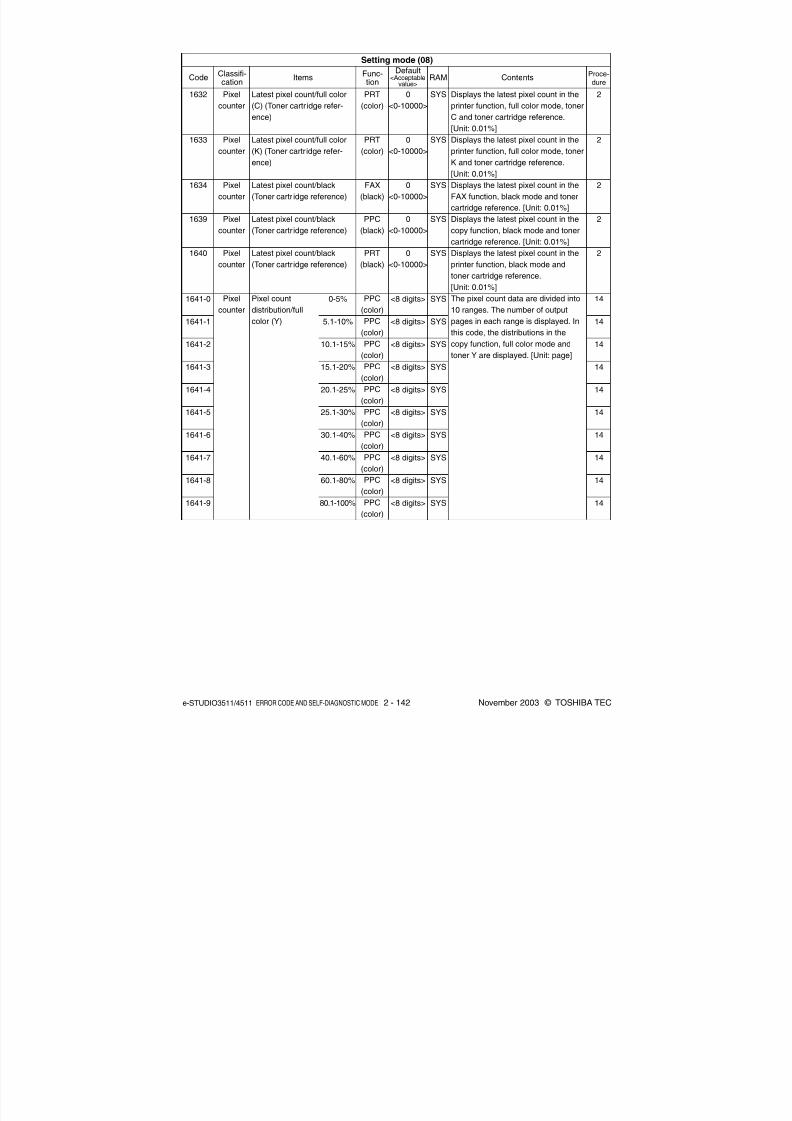
8/2/2019 ES-3511 Service Handbook
http://slidepdf.com/reader/full/es-3511-service-handbook 162/543
e-STUDIO3511/4511 ERROR CODE AND SELF-DIAGNOSTIC MODE 2 - 142 November 2003 © TOSHIBA TEC
Displays the latest pixel count in the
printer function, full color mode, toner
C and toner cartridge reference.
[Unit: 0.01%]
Displays the latest pixel count in theprinter function, full color mode, toner
K and toner cartridge reference.
[Unit: 0.01%]
Displays the latest pixel count in the
FAX function, black mode and toner
cartridge reference. [Unit: 0.01%]
Displays the latest pixel count in the
copy function, black mode and toner
cartridge reference. [Unit: 0.01%]
Displays the latest pixel count in the
printer function, black mode and
toner cartridge reference.
[Unit: 0.01%]
The pixel count data are divided into
10 ranges. The number of output
pages in each range is displayed. In
this code, the distributions in the
copy function, full color mode and
toner Y are displayed. [Unit: page]
2
2
2
2
2
14
14
14
14
14
14
14
14
14
14
PRT
(color)
PRT(color)
FAX
(black)
PPC
(black)
PRT
(black)
PPC
(color)
PPC
(color)
PPC
(color)
PPC
(color)
PPC
(color)
PPC
(color)
PPC
(color)
PPC
(color)
PPC
(color)
PPC
(color)
0
<0-10000>
0<0-10000>
0
<0-10000>
0
<0-10000>
0
<0-10000>
<8 digits>
<8 digits>
<8 digits>
<8 digits>
<8 digits>
<8 digits>
<8 digits>
<8 digits>
<8 digits>
<8 digits>
SYS
SYS
SYS
SYS
SYS
SYS
SYS
SYS
SYS
SYS
SYS
SYS
SYS
SYS
SYS
Latest pixel count/full color
(C) (Toner cartr idge refer-
ence)
Latest pixel count/full color(K) (Toner cartr idge refer-
ence)
Latest pixel count/black
(Toner cartr idge reference)
Latest pixel count/black
(Toner cartr idge reference)
Latest pixel count/black
(Toner cartr idge reference)
Pixel count
distribution/full
color (Y)
0-5%
5.1-10%
10.1-15%
15.1-20%
20.1-25%
25.1-30%
30.1-40%
40.1-60%
60.1-80%
80.1-100%
1632
1633
1634
1639
1640
1641-0
1641-1
1641-2
1641-3
1641-4
1641-5
1641-6
1641-7
1641-8
1641-9
Pixel
counter
Pixelcounter
Pixel
counter
Pixel
counter
Pixel
counter
Pixel
counter
Setting mode (08)
CodeClassifi-cation
ItemsFunc-tion
Default<Acceptable
value>RAM Contents
Proce-dure

8/2/2019 ES-3511 Service Handbook
http://slidepdf.com/reader/full/es-3511-service-handbook 163/543
November 2003 © TOSHIBA TEC 2 - 143 e-STUDIO3511/4511 ERROR CODE AND SELF-DIAGNOSTIC MODE
<8 digits>
<8 digits>
<8 digits>
<8 digits>
<8 digits>
<8 digits>
<8 digits>
<8 digits>
<8 digits>
<8 digits>
<8 digits>
<8 digits>
<8 digits>
<8 digits>
<8 digits>
<8 digits>
<8 digits>
<8 digits>
<8 digits>
<8 digits>
Setting mode (08)
CodeClassifi-cation
ItemsFunc-tion
Default<Acceptable
value>RAM Contents
Proce-dure
1642-0
1642-1
1642-2
1642-3
1642-4
1642-5
1642-6
1642-7
1642-8
1642-9
1643-0
1643-1
1643-2
1643-3
1643-4
1643-5
1643-6
1643-7
1643-8
1643-9
Pixel
counter
Pixel
counter
Pixel count
distribution/full
color (M)
Pixel count
distribution/full
color (C)
PPC
(color)
PPC
(color)
PPC(color)
PPC
(color)
PPC
(color)
PPC
(color)
PPC
(color)
PPC
(color)
PPC
(color)
PPC
(color)
PPC
(color)
PPC
(color)
PPC
(color)
PPC
(color)
PPC
(color)
PPC
(color)
PPC
(color)
PPC
(color)
PPC
(color)
PPC
(color)
SYS
SYS
SYS
SYS
SYS
SYS
SYS
SYS
SYS
SYS
SYS
SYS
SYS
SYS
SYS
SYS
SYS
SYS
SYS
SYS
The pixel count data are divided into
10 ranges. The number of output
pages in each range is displayed. In
this code, the distributions in the
copy function, full color mode andtoner M are displayed. [Unit: page]
The pixel count data are divided into
10 ranges. The number of output
pages in each range is displayed. In
this code, the distributions in the
copy function, full color mode and
toner C are displayed. [Unit: page]
14
14
14
14
14
14
14
14
14
14
14
14
14
14
14
14
14
14
14
14
0-5%
5.1-10%
10.1-15%
15.1-20%
20.1-25%
25.1-30%
30.1-40%
40.1-60%
60.1-80%
80.1-100%
0-5%
5.1-10%
10.1-15%
15.1-20%
20.1-25%
25.1-30%
30.1-40%
40.1-60%
60.1-80%
80.1-100%

8/2/2019 ES-3511 Service Handbook
http://slidepdf.com/reader/full/es-3511-service-handbook 164/543
e-STUDIO3511/4511 ERROR CODE AND SELF-DIAGNOSTIC MODE 2 - 144 November 2003 © TOSHIBA TEC
Setting mode (08)
CodeClassifi-cation
ItemsFunc-tion
Default<Acceptable
value>RAM Contents
Proce-dure
1644-0
1644-1
1644-2
1644-3
1644-4
1644-5
1644-6
1644-7
1644-8
1644-9
1645-0
1645-1
1645-2
1645-3
1645-4
1645-5
1645-6
1645-7
1645-8
1645-9
Pixel
counter
Pixel
counter
Pixel count
distribution/full
color (K)
Pixel count
distribution/full
color (Y)
0-5%
5.1-10%
10.1-15%
15.1-20%
20.1-25%
25.1-30%
30.1-40%
40.1-60%
60.1-80%
80.1-100%
0-5%
5.1-10%
10.1-15%
15.1-20%
20.1-25%
25.1-30%
30.1-40%
40.1-60%
60.1-80%
80.1-00%
PPC
(color)
PPC
(color)
PPC(color)
PPC
(color)
PPC
(color)
PPC
(color)
PPC
(color)
PPC
(color)
PPC
(color)
PPC
(color)
PRT
(color)
PRT
(color)
PRT
(color)
PRT
(color)
PRT
(color)
PRT
(color)
PRT
(color)
PRT
(color)
PRT
(color)
PRT
(color)
<8 digits>
<8 digits>
<8 digits>
<8 digits>
<8 digits>
<8 digits>
<8 digits>
<8 digits>
<8 digits>
<8 digits>
<8 digits>
<8 digits>
<8 digits>
<8 digits>
<8 digits>
<8 digits>
<8 digits>
<8 digits>
<8 digits>
<8 digits>
SYS
SYS
SYS
SYS
SYS
SYS
SYS
SYS
SYS
SYS
SYS
SYS
SYS
SYS
SYS
SYS
SYS
SYS
SYS
SYS
The pixel count data are divided into
10 ranges. The number of output
pages in each range is displayed. In
this code, the distributions in the
copy function, full color mode andtoner K are displayed. [Unit: page]
The pixel count data are divided into
10 ranges. The number of output
pages in each range is displayed. In
this code, the distributions in the
printer function, full color mode and
toner Y are displayed. [Unit: page]
14
14
14
14
14
14
14
14
14
14
14
14
14
14
14
14
14
14
14
14

8/2/2019 ES-3511 Service Handbook
http://slidepdf.com/reader/full/es-3511-service-handbook 165/543
November 2003 © TOSHIBA TEC 2 - 145 e-STUDIO3511/4511 ERROR CODE AND SELF-DIAGNOSTIC MODE
Setting mode (08)
CodeClassifi-cation
ItemsFunc-tion
Default<Acceptable
value>RAM Contents
Proce-dure
1646-0
1646-1
1646-2
1646-3
1646-4
1646-5
1646-6
1646-7
1646-8
1646-9
1647-0
1647-1
1647-2
1647-3
1647-4
1647-5
1647-6
1647-7
1647-8
1647-9
Pixel
counter
Pixel
counter
Pixel count
distribution/full
color (M)
Pixel count
distribution/full
color (C)
0-5%
5.1-10%
10.1-15%
15.1-20%
20.1-25%
25.1-30%
30.1-40%
40.1-60%
60.1-80%
80.1-100%
0-5%
5.1-10%
10.1-15%
15.1-20%
20.1-25%
25.1-30%
30.1-40%
40.1-60%
60.1-80%
80.1-100%
PRT
(color)
PRT
(color)
PRT(color)
PRT
(color)
PRT
(color)
PRT
(color)
PRT
(color)
PRT
(color)
PRT
(color)
PRT
(color)
PRT
(color)
PRT
(color)
PRT
(color)
PRT
(color)
PRT
(color)
PRT
(color)
PRT
(color)
PRT
(color)
PRT
(color)
PRT
(color)
<8 digits>
<8 digits>
<8 digits>
<8 digits>
<8 digits>
<8 digits>
<8 digits>
<8 digits>
<8 digits>
<8 digits>
<8 digits>
<8 digits>
<8 digits>
<8 digits>
<8 digits>
<8 digits>
<8 digits>
<8 digits>
<8 digits>
<8 digits>
SYS
SYS
SYS
SYS
SYS
SYS
SYS
SYS
SYS
SYS
SYS
SYS
SYS
SYS
SYS
SYS
SYS
SYS
SYS
SYS
The pixel count data are divided into
10 ranges. The number of output
pages in each range is displayed. In
this code, the distributions in the
printer function, full color mode andtoner M are displayed. [Unit: page]
The pixel count data are divided into
10 ranges. The number of output
pages in each range is displayed. In
this code, the distributions in the
printer function, full color mode and
toner C are displayed. [Unit: page]
14
14
14
14
14
14
14
14
14
14
14
14
14
14
14
14
14
14
14
14

8/2/2019 ES-3511 Service Handbook
http://slidepdf.com/reader/full/es-3511-service-handbook 166/543
e-STUDIO3511/4511 ERROR CODE AND SELF-DIAGNOSTIC MODE 2 - 146 November 2003 © TOSHIBA TEC
Setting mode (08)
CodeClassifi-cation
ItemsFunc-tion
Default<Acceptable
value>RAM Contents
Proce-dure
1648-0
1648-1
1648-2
1648-3
1648-4
1648-5
1648-6
1648-7
1648-8
1648-9
1649-0
1649-1
1649-2
1649-3
1649-4
1649-5
1649-6
1649-7
1649-8
1649-9
Pixel
counter
Pixel
counter
Pixel count
distribution/full
color (K)
Pixel count
distribution/black
0-5%
5.1-10%
10.1-15%
15.1-20%
20.1-25%
25.1-30%
30.1-40%
40.1-60%
60.1-80%
80.1-100%
0-5%
5.1-10%
10.1-15%
15.1-20%
20.1-25%
25.1-30%
30.1-40%
40.1-60%
60.1-80%
80.1-100%
PRT
(color)
PRT
(color)
PRT(color)
PRT
(color)
PRT
(color)
PRT
(color)
PRT
(color)
PRT
(color)
PRT
(color)
PRT
(color)
PPC
(black)
PPC
(black)
PPC
(black)
PPC
(black)
PPC
(black)
PPC
(black)
PPC
(black)
PPC
(black)
PPC
(black)
PPC
(black)
<8 digits>
<8 digits>
<8 digits>
<8 digits>
<8 digits>
<8 digits>
<8 digits>
<8 digits>
<8 digits>
<8 digits>
<8 digits>
<8 digits>
<8 digits>
<8 digits>
<8 digits>
<8 digits>
<8 digits>
<8 digits>
<8 digits>
<8 digits>
SYS
SYS
SYS
SYS
SYS
SYS
SYS
SYS
SYS
SYS
SYS
SYS
SYS
SYS
SYS
SYS
SYS
SYS
SYS
SYS
The pixel count data are divided into
10 ranges. The number of output
pages in each range is displayed. In
this code, the distributions in the
printer function, full color mode andtoner K are displayed. [Unit: page]
The pixel count data are divided into
10 ranges. The number of output
pages in each range is displayed. In
this code, the distributions in the
copy function and black mode are
displayed. [Unit: page]
14
14
14
14
14
14
14
14
14
14
14
14
14
14
14
14
14
14
14
14

8/2/2019 ES-3511 Service Handbook
http://slidepdf.com/reader/full/es-3511-service-handbook 167/543
November 2003 © TOSHIBA TEC 2 - 147 e-STUDIO3511/4511 ERROR CODE AND SELF-DIAGNOSTIC MODE
Setting mode (08)
CodeClassifi-cation
ItemsFunc-tion
Default<Acceptable
value>RAM Contents
Proce-dure
1650-0
1650-1
1650-2
1650-3
1650-4
1650-5
1650-6
1650-7
1650-8
1650-9
1651-0
1651-1
1651-2
1651-3
1651-4
1651-5
1651-6
1651-7
1651-8
1651-9
14
14
14
14
14
14
14
14
14
14
14
14
14
14
14
14
14
14
14
14
Pixel
counter
Pixel
counter
Pixel count
distribution/black
Pixel count
distribution/black
0-5%
5.1-10%
10.1-15%
15.1-20%
20.1-25%
25.1-30%
30.1-40%
40.1-60%
60.1-80%
80.1-100%
0-5%
5.1-10%
10.1-15%
15.1-20%
20.1-25%
25.1-30%
30.1-40%
40.1-60%
60.1-80%
80.1-100%
PRT
(black)
PRT
(black)
PRT(black)
PRT
(black)
PRT
(black)
PRT
(black)
PRT
(black)
PRT
(black)
PRT
(black)
PRT
(black)
FAX
(black)
FAX
(black)
FAX
(black)
FAX
(black)
FAX
(black)
FAX
(black)
FAX
(black)
FAX
(black)
FAX
(black)
FAX
(black)
<8 digits>
<8 digits>
<8 digits>
<8 digits>
<8 digits>
<8 digits>
<8 digits>
<8 digits>
<8 digits>
<8 digits>
<8 digits>
<8 digits>
<8 digits>
<8 digits>
<8 digits>
<8 digits>
<8 digits>
<8 digits>
<8 digits>
<8 digits>
SYS
SYS
SYS
SYS
SYS
SYS
SYS
SYS
SYS
SYS
SYS
SYS
SYS
SYS
SYS
SYS
SYS
SYS
SYS
SYS
The pixel count data are divided into
10 ranges. The number of output
pages in each range is displayed. In
this code, the distributions in the
printer function and black mode aredisplayed. [Unit: page]
The pixel count data are divided into
10 ranges. The number of output
pages in each range is displayed. In
this code, the distr ibutions in the FAX
function and black mode are dis-
played. [Unit: page]

8/2/2019 ES-3511 Service Handbook
http://slidepdf.com/reader/full/es-3511-service-handbook 168/543
e-STUDIO3511/4511 ERROR CODE AND SELF-DIAGNOSTIC MODE 2 - 148 November 2003 © TOSHIBA TEC
<<PM support mode related code>>
The management items at PM support mode can also be operated at setting mode (08).
The following items are displayed or set by using sub-codes at PM management setting in the
table below.
<Sub-codes>
0: Present number of output pages
- Means the present number of output pages.
1: Recommended number of output pages for replacement
- Means the recommended number of output pages for replacement.
2: Number of output pages at the last replacement
- Means the number of output pages at the last replacement.
3: Present drive counts
- Means the present drive counts (1 count = 2 seconds).
4: Recommended drive counts to be replaced
- Means the recommended drive counts for replacement (1 count = 2 seconds).
5: Driving counts at the last replacement
- Means the drive counts at the last replacement.
6: Present output pages for control
- Means the present number of output pages for controlling.
7: Present drive counts for control
- Means the present drive counts for controlling (1 count = 2 seconds).
8: Number of times replaced
- Counts up when clearing the counter of each unit in the PM Support Mode Screen.
Notes:
Sub-code 3 is equivalent to sub-code 7.
• When the value of sub-code 3 is changed, the value of sub-code 7 is also updated and vice versa.
• When "0" is set at one of sub-codes 0, 3, 6 and 7, the rest of them are automatically updated to "0".

8/2/2019 ES-3511 Service Handbook
http://slidepdf.com/reader/full/es-3511-service-handbook 169/543
November 2003 © TOSHIBA TEC 2 - 149 e-STUDIO3511/4511 ERROR CODE AND SELF-DIAGNOSTIC MODE
Photoconductive drum
Drum cleaning blade
Drum cleaner brush
Main charger grid
Main charger wire
Main charger wire cleaning
pad
Ozone filter
Developer material K
Developer material Y
Developer material M
Developer material C
1st transfer roller
1150-0 to 8
1158-0 to 8
1166-0 to 8
1174-0 to 8
1182-0 to 8
1190-0 to 8
1198-0 to 8
1200-0 to 8
1202-0 to 8
1204-0 to 8
1206-0 to 8
1214-0 to 8
1151
1159
1167
1175
1183
1191
1199
1201
1203
1205
1207
1215
PM managementsetting
<Procedure 4>
*Indicated in 8 digits
Date of previousreplacement<Procedure 2>
RemarksItems
<Default values of code 1150 (e-STUDIO3511/4511)>
Sub-codes 0, 2, 3, 5, 6, 7, 8: 0/0
Sub-code 1: 160000/200000
Sub-code 4: 315000/315000
<Default values of code 1158 (e-STUDIO3511/4511)>
Sub-codes 0, 2, 3, 5, 6, 7, 8: 0/0
Sub-code 1: 160000/200000
Sub-code 4: 315000/315000
<Default values of code 1166 (e-STUDIO3511/4511)>
Sub-codes 0, 2, 3, 5, 6, 7, 8: 0/0
Sub-code 1: 160000/200000
Sub-code 4: 315000/315000
<Default values of code 1174 (e-STUDIO3511/4511)>
Sub-codes 0, 2, 3, 5, 6, 7, 8: 0/0
Sub-code 1: 160000/200000
Sub-code 4: 315000/315000
<Default values of code 1182 (e-STUDIO3511/4511)>Sub-codes 0, 2, 3, 5, 6, 7, 8: 0/0
Sub-code 1: 160000/200000
Sub-code 4: 315000/315000
<Default values of code 1190 (e-STUDIO3511/4511)>
Sub-codes 0, 2, 3, 5, 6, 7, 8: 0/0
Sub-code 1: 160000/200000
Sub-code 4: 315000/315000
<Default values of code 1198 (e-STUDIO3511/4511)>
Sub-codes 0, 2, 3, 5, 6, 7, 8: 0/0
Sub-code 1: 160000/200000
Sub-code 4: 315000/315000
<Default values of code 1200 (e-STUDIO3511/4511)>
Sub-codes 0, 2, 3, 5, 6, 7, 8: 0/0
Sub-code 1: 120000/150000
Sub-code 4: 116000/116000
<Default values of code 1202 (e-STUDIO3511/4511)>
Sub-codes 0, 2, 3, 5, 6, 7, 8: 0/0
Sub-code 1: 30000/37500
Sub-code 4: 28000/28000
<Default values of code 1204 (e-STUDIO3511/4511)>
Sub-codes 0, 2, 3, 5, 6, 7, 8: 0/0
Sub-code 1: 30000/37500
Sub-code 4: 28000/28000
<Default values of code 1206 (e-STUDIO3511/4511)>
Sub-codes 0, 2, 3, 5, 6, 7, 8: 0/0
Sub-code 1: 30000/37500
Sub-code 4: 28000/28000
<Default values of code 1214 (e-STUDIO3511/4511)>
Sub-codes 0, 2, 3, 5, 6, 7, 8: 0/0
Sub-code 1: 480000/600000
Sub-code 4: 1010000/1010000
04/05

8/2/2019 ES-3511 Service Handbook
http://slidepdf.com/reader/full/es-3511-service-handbook 170/543
e-STUDIO3511/4511 ERROR CODE AND SELF-DIAGNOSTIC MODE 2 - 150 November 2003 © TOSHIBA TEC
1229
1231
1233
1241
1245
1251
1259
1261
1271
1273
1277
1279
1283
<Default values of code 1228 (e-STUDIO3511/4511)>
Sub-codes 0, 2, 3, 5, 6, 7, 8: 0/0
Sub-code 1: 480000/600000
Sub-code 4: 1010000/1010000
<Default values of code 1230 (e-STUDIO3511/4511)>
Sub-codes 0, 2, 3, 5, 6, 7, 8: 0/0
Sub-code 1: 240000/300000
Sub-code 4: 505000/505000
<Default values of code 1232 (e-STUDIO3511/4511)>
Sub-codes 0, 2, 3, 5, 6, 7, 8: 0/0
Sub-code 1: 160000/200000
Sub-code 4: 337000/337000
<Default values of code 1240 (e-STUDIO3511/4511)>
Sub-codes 0, 2, 3, 5, 6, 7, 8: 0/0
Sub-code 1: 240000/300000
Sub-code 4: 312000/312000
<Default values of code 1244 (e-STUDIO3511/4511)>Sub-codes 0, 2, 3, 5, 6, 7, 8: 0/0
Sub-code 1: 240000/300000
Sub-code 4: 312000/312000
<Default values of code 1250 (e-STUDIO3511/4511)>
Sub-codes 0, 2, 3, 5, 6, 7, 8: 0/0
Sub-code 1: 120000/150000
Sub-code 4: 285000/285000
<Default values of code 1258 (e-STUDIO3511/4511)>
Sub-codes 0, 2, 3, 5, 6, 7, 8: 0/0
Sub-code 1: 120000/150000
Sub-code 4: 285000/285000
<Default values of code 1260 (e-STUDIO3511/4511)>
Sub-codes 0, 2, 3, 5, 6, 7, 8: 0/0
Sub-code 1: 120000/150000
Sub-code 4: 285000/285000
<Default values of code 1270 (e-STUDIO3511/4511)>
Sub-codes 0, 2, 3, 5, 6, 7, 8: 0/0
Sub-code 1: 120000/150000
Sub-code 4: 285000/285000
<Default values of code 1272 (e-STUDIO3511/4511)>
Sub-codes 0, 2, 3, 5, 6, 7, 8: 0/0
Sub-code 1: 120000/150000
Sub-code 4: 285000/285000
<Default values of code 1276 (e-STUDIO3511/4511)>
Sub-codes 0, 2, 3, 5, 6, 7, 8: 0/0
Sub-code 1: 120000/150000
Sub-code 4: 285000/285000
<Default values of code 1278 (e-STUDIO3511/4511)>
Sub-codes 0, 2, 3, 5, 6, 7, 8: 0/0
Sub-code 1: 120000/150000
Sub-code 4: 285000/285000
<Default values of code 1282 (e-STUDIO3511/4511)>
Sub-codes 0, 2, 8: 0/0
Sub-code 1: 120000/120000
1228-0 to 8
1230-0 to 8
1232-0 to 8
1240-0 to 8
1244-0 to 8
1250-0 to 8
1258-0 to 8
1260-0 to 8
1270-0 to 8
1272-0 to 8
1276-0 to 8
1278-0 to 8
1282-0, 1, 2, 8
Transfer belt
Transfer belt dr iving roller
cleaning brush
Transfer belt cleaning blade
2nd transfer roller
2nd transfer roller cleaningbrush
Pressure roller
Oil roller
Cleaning roller
Pressure roller separation
finger
Fuser belt
Fuser belt guide
Pressure roller scraper
Pickup roller (RADF)
PM managementsetting
<Procedure 4>
*Indicated in 8 digits
Date of previousreplacement<Procedure 2>
RemarksItems
04/05
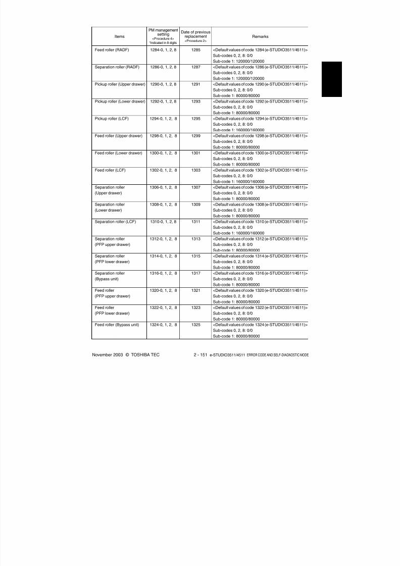
8/2/2019 ES-3511 Service Handbook
http://slidepdf.com/reader/full/es-3511-service-handbook 171/543
November 2003 © TOSHIBA TEC 2 - 151 e-STUDIO3511/4511 ERROR CODE AND SELF-DIAGNOSTIC MODE
1284-0, 1, 2, 8
1286-0, 1, 2, 8
1290-0, 1, 2, 8
1292-0, 1, 2, 8
1294-0, 1, 2, 8
1298-0, 1, 2, 8
1300-0, 1, 2, 8
1302-0, 1, 2, 8
1306-0, 1, 2, 8
1308-0, 1, 2, 8
1310-0, 1, 2, 8
1312-0, 1, 2, 8
1314-0, 1, 2, 8
1316-0, 1, 2, 8
1320-0, 1, 2, 8
1322-0, 1, 2, 8
1324-0, 1, 2, 8
1285
1287
1291
1293
1295
1299
1301
1303
1307
1309
1311
1313
1315
1317
1321
1323
1325
Feed roller (RADF)
Separation roller (RADF)
Pickup roller (Upper drawer)
Pickup roller (Lower drawer)
Pickup roller (LCF)
Feed roller (Upper drawer)
Feed roller (Lower drawer)
Feed roller (LCF)
Separation roller
(Upper drawer)
Separation roller
(Lower drawer)
Separation roller (LCF)
Separation roller
(PFP upper drawer)
Separation roller
(PFP lower drawer)
Separation roller
(Bypass unit)
Feed roller
(PFP upper drawer)
Feed roller
(PFP lower drawer)
Feed roller (Bypass unit)
PM managementsetting
<Procedure 4>
*Indicated in 8 digits
Date of previousreplacement<Procedure 2>
RemarksItems
<Default values of code 1284 (e-STUDIO3511/4511)>
Sub-codes 0, 2, 8: 0/0
Sub-code 1: 120000/120000
<Default values of code 1286 (e-STUDIO3511/4511)>
Sub-codes 0, 2, 8: 0/0
Sub-code 1: 120000/120000
<Default values of code 1290 (e-STUDIO3511/4511)>
Sub-codes 0, 2, 8: 0/0
Sub-code 1: 80000/80000
<Default values of code 1292 (e-STUDIO3511/4511)>
Sub-codes 0, 2, 8: 0/0
Sub-code 1: 80000/80000
<Default values of code 1294 (e-STUDIO3511/4511)>
Sub-codes 0, 2, 8: 0/0
Sub-code 1: 160000/160000
<Default values of code 1298 (e-STUDIO3511/4511)>
Sub-codes 0, 2, 8: 0/0Sub-code 1: 80000/80000
<Default values of code 1300 (e-STUDIO3511/4511)>
Sub-codes 0, 2, 8: 0/0
Sub-code 1: 80000/80000
<Default values of code 1302 (e-STUDIO3511/4511)>
Sub-codes 0, 2, 8: 0/0
Sub-code 1: 160000/160000
<Default values of code 1306 (e-STUDIO3511/4511)>
Sub-codes 0, 2, 8: 0/0
Sub-code 1: 80000/80000
<Default values of code 1308 (e-STUDIO3511/4511)>
Sub-codes 0, 2, 8: 0/0
Sub-code 1: 80000/80000
<Default values of code 1310 (e-STUDIO3511/4511)>
Sub-codes 0, 2, 8: 0/0
Sub-code 1: 160000/160000
<Default values of code 1312 (e-STUDIO3511/4511)>
Sub-codes 0, 2, 8: 0/0
Sub-code 1: 80000/80000
<Default values of code 1314 (e-STUDIO3511/4511)>
Sub-codes 0, 2, 8: 0/0
Sub-code 1: 80000/80000
<Default values of code 1316 (e-STUDIO3511/4511)>
Sub-codes 0, 2, 8: 0/0
Sub-code 1: 80000/80000
<Default values of code 1320 (e-STUDIO3511/4511)>
Sub-codes 0, 2, 8: 0/0
Sub-code 1: 80000/80000
<Default values of code 1322 (e-STUDIO3511/4511)>
Sub-codes 0, 2, 8: 0/0
Sub-code 1: 80000/80000
<Default values of code 1324 (e-STUDIO3511/4511)>
Sub-codes 0, 2, 8: 0/0
Sub-code 1: 80000/80000

8/2/2019 ES-3511 Service Handbook
http://slidepdf.com/reader/full/es-3511-service-handbook 172/543
e-STUDIO3511/4511 ERROR CODE AND SELF-DIAGNOSTIC MODE 2 - 152 November 2003 © TOSHIBA TEC
1328-0, 1, 2, 8
1330-0, 1, 2, 8
1332-0, 1, 2, 8
1329
1331
1333
Pickup roller
(PFP upper drawer)
Pickup roller
(PFP lower drawer)
Pickup roller (Bypass unit)
PM managementsetting
<Procedure 4>
*Indicated in 8 digits
Date of previousreplacement<Procedure 2>
RemarksItems
<Default values of code 1328 (e-STUDIO3511/4511)>
Sub-codes 0, 2, 8: 0/0
Sub-code 1: 80000/80000
<Default values of code 1330 (e-STUDIO3511/4511)>
Sub-codes 0, 2, 8: 0/0
Sub-code 1: 80000/80000
<Default values of code 1332 (e-STUDIO3511/4511)>
Sub-codes 0, 2, 8: 0/0
Sub-code 1: 80000/80000
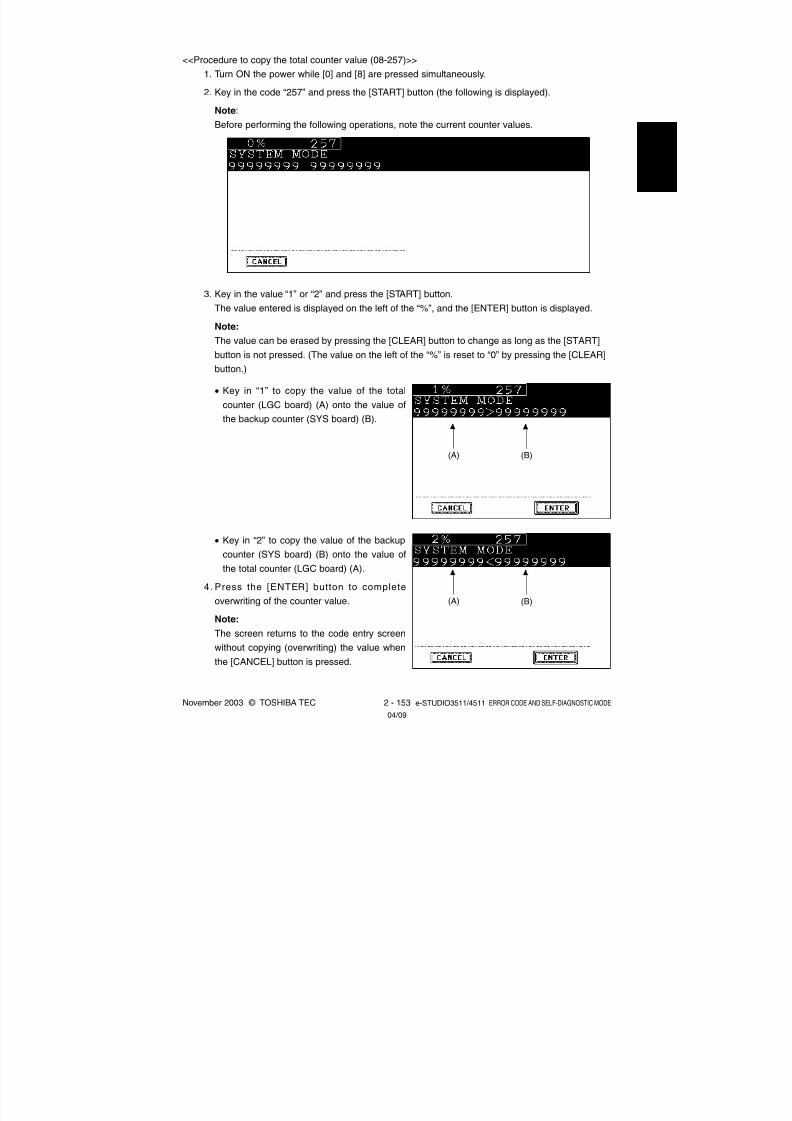
8/2/2019 ES-3511 Service Handbook
http://slidepdf.com/reader/full/es-3511-service-handbook 173/543
November 2003 © TOSHIBA TEC 2 - 153 e-STUDIO3511/4511 ERROR CODE AND SELF-DIAGNOSTIC MODE
<<Procedure to copy the total counter value (08-257)>>
1. Turn ON the power while [0] and [8] are pressed simultaneously.
2. Key in the code “257” and press the [START] button (the following is displayed).
Note:
Before performing the following operations, note the current counter values.
3. Key in the value “1” or “2” and press the [START] button.
The value entered is displayed on the left of the “%”, and the [ENTER] button is displayed.
Note:
The value can be erased by pressing the [CLEAR] button to change as long as the [START]
button is not pressed. (The value on the left of the “%” is reset to “0” by pressing the [CLEAR]
button.)
• Key in “1” to copy the value of the total
counter (LGC board) (A) onto the value of
the backup counter (SYS board) (B).
• Key in “2” to copy the value of the backup
counter (SYS board) (B) onto the value of
the total counter (LGC board) (A).
4. Press the [ENTER] button to complete
overwriting of the counter value.
Note:
The screen returns to the code entry screen
without copying (overwriting) the value when
the [CANCEL] button is pressed.
(A) (B)
(A) (B)
04/09

8/2/2019 ES-3511 Service Handbook
http://slidepdf.com/reader/full/es-3511-service-handbook 174/543
e-STUDIO3511/4511 ERROR CODE AND SELF-DIAGNOSTIC MODE 2 - 154 November 2003 © TOSHIBA TEC
2.2.6 Pixel counter
(1) Outline
Pixel counter is a function that counts the number of dots emitted by the laser and converts it into
the print ratio (%) per standard paper size. This “Print ratio (%) per standard paper size” is called
Pixel count (%).
This function enables you to know how each user uses the equipment and to grasp the tendency of
toner consumption (number of output pages per cartridge).
(2) Factors affecting toner consumption
Standard number of output pages per cartridge shows the average number of output pages under
the condition that the data of print ratio 6% is printed on the standard paper size (A4/LT) at a normal
temperature and humidity.
However, users do not always print under the above condition. As for the type of original, copy/print
mode and environment, each user has different tendency, and as a result, the number of output
pages per cartridge becomes different depending on the user.
The major factors affecting toner consumption are as follows:
(a) Original/Data coverage
(b) Original/Data density
(c) Original/Print mode
(d) Density setting
Also there are other factors in addition to the above, such as environment, individual difference of
equipment, difference in lot quality of materials, toner density and drum surface potential.

8/2/2019 ES-3511 Service Handbook
http://slidepdf.com/reader/full/es-3511-service-handbook 175/543
November 2003 © TOSHIBA TEC 2 - 155 e-STUDIO3511/4511 ERROR CODE AND SELF-DIAGNOSTIC MODE
Fig. 2-203 Factors affecting toner consumption and the tendency
T o n e r c o n s u m p t i o
n
T o n e r c o n s u m p t i o n
T o n e r c o n s u m p t i o n
T o n e r c o n s u m p t i o n
Original coverage Original density
Original mode
Density setting
TEXT /PHOTO
TEXT PHOTO PRINTEDIMAGE
MAP Manualdensity
-5
Manualdensity
-1
Automaticdensity
ManualdensityCenter
Manualdensity
+1
Manualdensity
+5
The general relations between the above 4 factors and toner consumption per output page in the copy
function are as follows:

8/2/2019 ES-3511 Service Handbook
http://slidepdf.com/reader/full/es-3511-service-handbook 176/543
e-STUDIO3511/4511 ERROR CODE AND SELF-DIAGNOSTIC MODE 2 - 156 November 2003 © TOSHIBA TEC
(3) Details of pixel counter
(a) Toner cartridge reference and service technician reference
The pixel counter function in this equipment has 2 references, toner cartridge reference and
service technician reference.
• Toner cartridge reference
This is a system that accumulates data on each color between the installation of a new toner
cartridge and next installation.
The installation of new toner cartridge is judged when the total number of pixel count or output
pages after the detection of toner empty has exceeded the threshold.
The threshold to be used is selectable in the setting mode (08-1506) between the pixel count
and output pages (0: Output pages 1: Pixel counter). The threshold of pixel count is set in the
setting mode (08-1508) and that of output pages is set in the setting mode (08-1507).
When the new toner cartridge is judged as installed, the data related with the previous cartridge
is cleared and replaced with the data after the installation of new cartridge.
Clearing of the counter of the toner cartridge reference is performed in the setting mode
(08-1503).
• Service technician reference
This is a system that accumulates data between clearing the counter of the service technician
reference by service technician and subsequently clearing the same counter.
Clearing of the counter of the service technician reference is performed in the setting mode
(08-1502).
(b) Print count (number of output pages)
The number of output pages shown at the pixel counter is counted after converting all paper
sizes to the standard size (A4/LT). Printing on other than the standard size is converted by paper
area ratio. The standard size is set in the setting mode (08-1500).
The examples of conversion are as follows:
Ex.) 1. “1” is added to the print count when printing on A4/LT size.
2. “2” is added to the print count when printing on A3/LD size. (area ratio to A4/LT: 200%)
3. “1.49” is added to the print count when printing on B4 size. (area ratio to A4: 149%)4. “1.27” is added to the print count when printing on LG size. (area ratio to LT: 127%)

8/2/2019 ES-3511 Service Handbook
http://slidepdf.com/reader/full/es-3511-service-handbook 177/543
November 2003 © TOSHIBA TEC 2 - 157 e-STUDIO3511/4511 ERROR CODE AND SELF-DIAGNOSTIC MODE
(c) Pixel count (%)
Pixel count (%) shows the ratio of laser emitting pixels to all pixels on standard paper.
The examples of pixel count are as follows:
Note: In the following examples, ‘solid copy’ is considered to be 100%. But since the image has
4 margins, it never becomes 100% actually.
Ex.) 1. Printing 5 pages on A4/LT size with solid copy (Laser emits to all pixels.)
→ Pixel count: 100%, Print count: 5
2. Printing 5 pages on A4/LT size with blank copy (Laser never emits.)
→ Pixel count: 0%, Print count: 5
3. Printing 2 pages on A4/LT size with solid copy (Laser emits to all pixels.)
Printing 2 pages on A4/LT size with blank copy (Laser never emits.)
→ Pixel count: 50%, Print count: 4
4. Printing 3 pages on A4/LT size with 6% of laser emission
Printing 1 page on A4/LT size with 2% of laser emission
→ Pixel count: 5%, Print count: 4
5. Printing 2 pages on A3/LD size with solid copy (Laser emits to all pixels.)
→ Pixel count: 100%, Print count: 4
6. Printing 2 pages on A3/LD size with 6% of laser emission
→ Pixel count: 6%, Print count: 4
(d) Average pixel count (%) and latest pixel count (%)
There are 2 types of the value calculated as the pixel count, average pixel count (%) and latest
pixel count (%).
1. Average pixel count (%)
The average value of all pixel count data after each reference data is cleared is calculated
and displayed.
2. Latest pixel count (%)
The value is displayed for printing just before the pixel counter is confirmed.

8/2/2019 ES-3511 Service Handbook
http://slidepdf.com/reader/full/es-3511-service-handbook 178/543
e-STUDIO3511/4511 ERROR CODE AND SELF-DIAGNOSTIC MODE 2 - 158 November 2003 © TOSHIBA TEC
Toner cartridge referenceService technician reference
Full color/Twin color
Yellow Magenta Cyan Black Total Yellow Magenta Cyan BlackBlack
Copy function
Printer function
FAX function
Total
: With data
: Without data
(e) Type of calculated data
Since this is multifunctional and color equipment, the data of pixel count is calculated for each
function and color.
The following list is the information that can be confirmed by LCD screen. But actually, more
information can be confirmed by the setting mode (08).
See after-mentioned (5)-(c) for details.
Table 2-201 Type of calculated data
(f) Setting related with the pixel counter function
(f-1) Standard paper size setting
The standard paper size (A4 or LT) to convert it into the pixel count is selected (08-1500).
(f-2) Pixel counter display setting
Whether or not to display the pixel counter on the LCD screen is selected (08-1504).
(f-3) Display reference setting
The reference when displaying the pixel counter on the LCD screen (toner cartridge refer-
ence or service technician reference) is selected (08-1505).
(f-4) Determination counter of toner empty
This is the counter to determine the replacement of new toner cartridge after the toner
empty is detected.
After the toner empty is detected by the auto-toner sensor, this counter checks if toner
empty is not detected one more time while the specified number of pixel count or output
pages is counted.
(f-5) Pixel counter clearing
There are 3 types for the pixel count clear as follows:
08-1501: All information related to the pixel count is cleared.
08-1502: All information related to the service technician reference pixel count is cleared.
08-1503: All information related to the toner cartridge reference pixel count is cleared.

8/2/2019 ES-3511 Service Handbook
http://slidepdf.com/reader/full/es-3511-service-handbook 179/543
November 2003 © TOSHIBA TEC 2 - 159 e-STUDIO3511/4511 ERROR CODE AND SELF-DIAGNOSTIC MODE
(4) Relation between pixel count and toner consumption
The user’s printing out the image with large coverage or high density may cause the large value of
pixel count. And the setting that toner consumption becomes high in the original mode or density
setting may cause it as well.
In this case, the replacement cycle of toner cartridge is faster than the standard number of output
pages. Therefore, this trend needs to be grasped for the service.
The relation between pixel count and number of output pages per cartridge is as follows:
Fig. 2-204 Pixel count and number of output pages per cartridge
6% 12% 60%
X
Y
Y/2
X/2
Y/10
X/10
Standard number of output pages (K)
Standard number of output pages (Y, M, C)
N u m b e r o f o u t p u t p a g e s p e r
c a r t r i d g e ( P a g e )
Pixel count (%)

8/2/2019 ES-3511 Service Handbook
http://slidepdf.com/reader/full/es-3511-service-handbook 180/543
e-STUDIO3511/4511 ERROR CODE AND SELF-DIAGNOSTIC MODE 2 - 160 November 2003 © TOSHIBA TEC
(5) Pixel counter confirmation
(a) Display on LCD screen
Whether or not to display the pixel counter on the LCD screen is selected (0: Displayed, 1: Not
displayed) in the setting mode (08-1504), and whether or not to display it at the service techni-
cian reference or toner cartridge reference is selected (0: Service technician reference, 1: Toner
cartridge reference) in the setting mode (08-1505).
The following screen is displayed when the buttons, [USER FUNCTIONS], [COUNTER] and
[PIXEL COUNTER] are pressed in this order after “Displayed” is selected with the code above
and the power is, as usual, turned ON. (The displayed buttons are depending on the setting of
08-1505.)
Table 2-205 Reference selection screen
When selecting and pressing the button in the above screen, each pixel counter screen is
displayed.
[TONER CARTRIDGE] button: Information screen of toner cartridge reference is displayed.
[SERVICE (COLOR)] button: Information screen of service technician reference (full color) is
displayed.
[SERVICE (BLACK)] button: Information screen of service technician reference (black) is
displayed.

8/2/2019 ES-3511 Service Handbook
http://slidepdf.com/reader/full/es-3511-service-handbook 181/543
November 2003 © TOSHIBA TEC 2 - 161 e-STUDIO3511/4511 ERROR CODE AND SELF-DIAGNOSTIC MODE
The following screen is displayed when pressing the [TONER CARTRIDGE] button.
Table 2-206 Information screen of toner cartridge reference
The following screen is displayed when pressing the [SERVICE (COLOR)] button.
Table 2-207 Information screen of service technician reference (full color)
The following screen is displayed when pressing the [SERVICE (BLACK)] button.
Table 2-208 Information screen of service technician reference (black)

8/2/2019 ES-3511 Service Handbook
http://slidepdf.com/reader/full/es-3511-service-handbook 182/543
e-STUDIO3511/4511 ERROR CODE AND SELF-DIAGNOSTIC MODE 2 - 162 November 2003 © TOSHIBA TEC
Table 2-210 Data list of service technician reference
PIXEL COUNTER CODE LIST
TONERCARTRIDGE
No012
91011
DATE200304232003042320030423
200304232003042320030423
FAX- - -- - -- - -
123451234512345
PPC123451234512345
123451234512345
PRN234562345623456
234562345623456
TOTAL456784567845678
456784567845678
2003.4.23 09:55
Col.YYY
KKK
Print Count [LT/A4]Average Pixel Count [%]Latest Pixel Count [%]
Print Count [LT/A4]Average Pixel Count [%]Latest Pixel Count [%]
(b) Data list printing
The data for pixel counter can be printed in the list print mode (9S).
9S-104: The data of the toner cartridge reference is printed.
9S-105: The data of service technician reference is printed.
Table 2-209 Data list of toner cartridge reference
PIXEL COUNTER CODE LIST
SERVICEMAN
No012
91011
DATE200304232003042320030423
200304232003042320030423
FAX- - -- - -- - -
123451234512345
PPC123451234512345
123451234512345
PRN234562345623456
234562345623456
TOTAL456784567845678
456784567845678
2003.4.23 09:55
Col.YYY
KKK
Print Count [LT/A4]Average Pixel Count [%]Latest Pixel Count [%]
Print Count [LT/A4]Average Pixel Count [%]Latest Pixel Count [%]

8/2/2019 ES-3511 Service Handbook
http://slidepdf.com/reader/full/es-3511-service-handbook 183/543
November 2003 © TOSHIBA TEC 2 - 163 e-STUDIO3511/4511 ERROR CODE AND SELF-DIAGNOSTIC MODE
Magenta
1559
1610
1627
1560
1616
1631
-
-
-
1622
Cyan
1561
1611
1628
1562
1617
1632
-
-
-
1623
Black
1552
1612
1629
1554
1618
1633
-
-
-
-
Yellow
1557
1609
1626
1558
1615
1630
-
-
-
1621
Full color/Twin color
(c) Display in the setting mode (08)
Information of pixel count can be also checked in the setting mode (08).
For details, see “2.2.5 Setting mode (08)”.
(c-1) Print count, pixel count
Table 2-202 Pixel count code table (toner cartridge reference)
Copy
function
Printer
function
FAX function
Total
Print count
(page)Average pixel count
(%)
Latest pixel count
(%)
Print count
(page)
Average pixel count
(%)
Latest pixel count(%)
Print count
(page)
Average pixel count
(%)
Latest pixel count
(%)
Average pixel count
(%)
Black
1553
1613
1639
1555
1619
1640
1556
1625
1634
-
Black(at color)
+
Black
-
1614
-
-
1620
-
-
-
-
1624
Yellow
-
1578
1597
-
1583
1602
-
-
-
1588
Magenta
-
1579
1598
-
1584
1603
-
-
-
1598
Cyan
-
1580
1599
-
1585
1604
-
-
-
1590
Total
1547
1577
1596
1549
1582
1601
-
-
-
1587
Full color/Twin color
Copy
function
Printer
function
FAX function
Total
Print count
(page)
Average pixel count
(%)
Latest pixel count
(%)
Print count
(page)
Average pixel count
(%)
Latest pixel count
(%)Print count
(page)
Average pixel count
(%)
Latest pixel count
(%)
Average pixel count(%)
Black
-
1581
1600
-
1586
1605
-
-
-
1591
Black
1548
1592
1606
1550
1593
1607
1551
1594
1608
1595
Table 2-203 Pixel count code table (service technician reference)
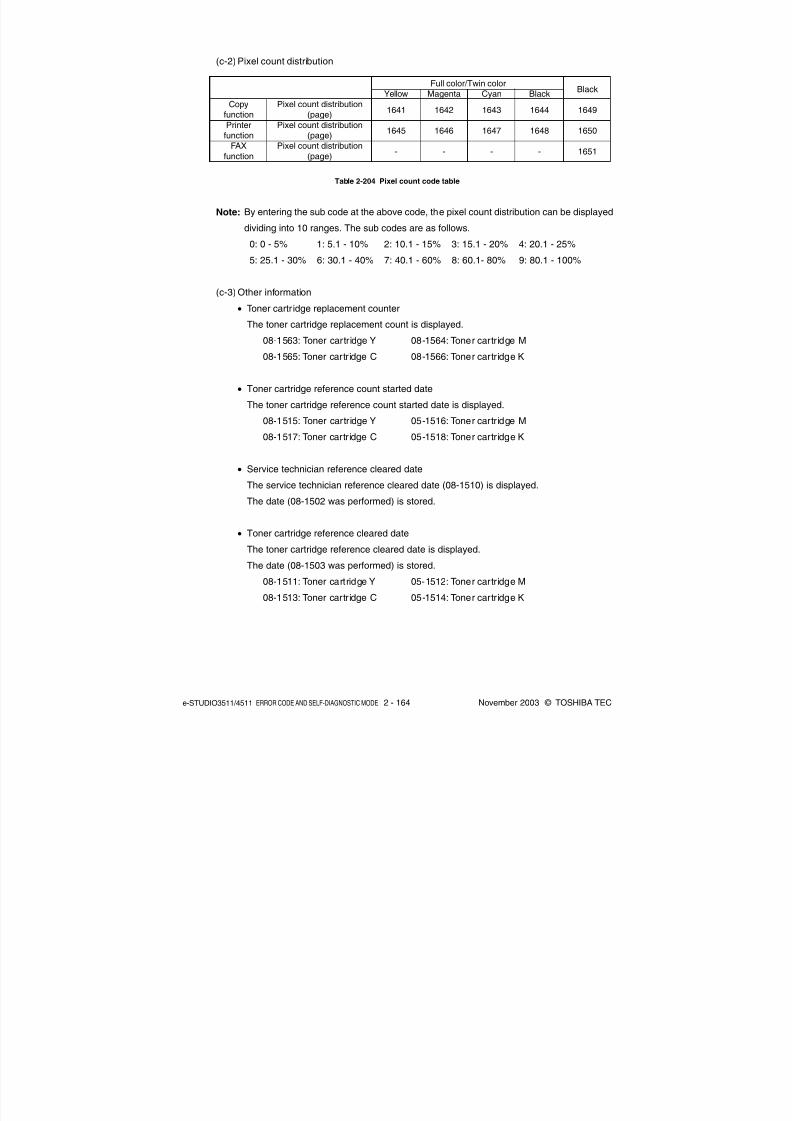
8/2/2019 ES-3511 Service Handbook
http://slidepdf.com/reader/full/es-3511-service-handbook 184/543
e-STUDIO3511/4511 ERROR CODE AND SELF-DIAGNOSTIC MODE 2 - 164 November 2003 © TOSHIBA TEC
Yellow
1641
1645
-
Magenta
1642
1646
-
Cyan
1643
1647
-
Full color/Twin color
Copy
function
Printer
function
FAX
function
Pixel count distribution
(page)
Pixel count distribution
(page)
Pixel count distribution
(page)
Black
1644
1648
-
Black
1649
1650
1651
(c-2) Pixel count distribution
Table 2-204 Pixel count code table
Note: By entering the sub code at the above code, the pixel count distribution can be displayed
dividing into 10 ranges. The sub codes are as follows.
0: 0 - 5% 1: 5.1 - 10% 2: 10.1 - 15% 3: 15.1 - 20% 4: 20.1 - 25%
5: 25.1 - 30% 6: 30.1 - 40% 7: 40.1 - 60% 8: 60.1- 80% 9: 80.1 - 100%
(c-3) Other information
• Toner cartr idge replacement counter
The toner cartridge replacement count is displayed.
08-1563: Toner cartridge Y 08-1564: Toner cartridge M
08-1565: Toner cartridge C 08-1566: Toner cartridge K
• Toner cartridge reference count started date
The toner cartridge reference count started date is displayed.
08-1515: Toner cartridge Y 05-1516: Toner cartridge M
08-1517: Toner cartridge C 05-1518: Toner cartridge K
• Service technician reference cleared date
The service technician reference cleared date (08-1510) is displayed.
The date (08-1502 was performed) is stored.
• Toner cartridge reference cleared date
The toner cartridge reference cleared date is displayed.
The date (08-1503 was performed) is stored.
08-1511: Toner cartridge Y 05-1512: Toner cartridge M
08-1513: Toner cartridge C 05-1514: Toner cartridge K

8/2/2019 ES-3511 Service Handbook
http://slidepdf.com/reader/full/es-3511-service-handbook 185/543
November 2003 © TOSHIBA TEC 2 - 165 e-STUDIO3511/4511 ERROR CODE AND SELF-DIAGNOSTIC MODE
[Image position] 305, 306
[Distortion] 308
[Reproduction ratio] 340, 884, 1060
[Carriage position] 359, 360[Fixed value] 364, 363
[Margin] 430, 431, 432, 433, 435, 436, 437, 438,
439
[Image density] 501, 503, 504, 505, 506, 507,
508, 509, 510, 512, 514, 515, 710, 714, 715,
719, 720, 724, 725, 729, 845, 846, 847, 850,
851, 852, 855, 856, 857, 860, 861, 862, 1550,
1551, 1552, 1553, 1554, 1560, 1561, 1562,
1563, 1564, 1570, 1571, 1572, 1573, 1574,
1580, 1581, 1582, 1583, 1584
User interface
Scanner
Image
2.2.7 Classification List of Adjustment Mode (05) / Setting Mode (08)
Classification Adjustment Mode (05) Setting Mode (08)
[Date/Time] 200, 638, 640
[Timer] 204, 205, 206, 260, 261, 262
[Screen] 207, 602
[File] 209, 218, 219, 264, 288
[Language] 220, 221[Administrator] 263
[Scanning] 265, 266, 273, 274
[Box] 267, 270
[HDD] 271
[Address book] 269
[E-mail] 272
[Default setting] 275, 276, 277, 278, 279, 280, 281,
282, 283, 284, 285, 286, 289, 331, 480, 503, 550,
585, 587, 588, 603, 604, 607, 618, 642
[Raw printing] 290, 291, 292, 293, 294, 295,
296, 297, 298, 299
[Copy volume] 300[Original counter] 302
[Automatic calibration] 595, 632
[AMS] 605
[Control panel] 610
[Book duplexing] 611
[Summer time] 612
[Paper size] 613
[Department management] 617, 620, 621, 622,
623, 624, 672
[Sorting] 627, 634, 641, 649
[Original direction] 628
[Image shift] 636
[Color specification] 643, 644
[Edit copying] 645, 646
[Box printing] 647
[X in 1] 650
[Annotation] 651, 657
[Automatic transferring] 660, 661
[Indicator] 671
[Priority drawer] 689
[Paper type] 697
[Error diffusion / Dither] 502
[ACS] 268, 609-0 to 4
[Smoothing] 560, 561, 562
[Image quality] 586, 589
[Gamma correction] 597
04/05

8/2/2019 ES-3511 Service Handbook
http://slidepdf.com/reader/full/es-3511-service-handbook 186/543
e-STUDIO3511/4511 ERROR CODE AND SELF-DIAGNOSTIC MODE 2 - 166 November 2003 © TOSHIBA TEC
Classification Adjustment Mode (05) Setting Mode (08)
[Range correction] 532, 533, 534, 570, 571,
572, 693, 694, 695, 825, 826, 827, 828, 830,
831, 832, 833, 835, 836, 837, 838
[Color deviation correction] 417-0 to 3, 418-0 to 3
[Gamma adjustment] 580, 1000, 1001, 1002,
1003, 1642, 1643
[Gamma balance] 590-0 to 2, 591-0 to 2, 592-0
to 2, 596-0 to 2, 597-0 to 2, 598-0 to 2, 599-0 to
2, 880-0 to 2, 880-0 to 2, 881-0 to 2, 882-0 to 2,
883-0 to 2, 1000
[Sharpness] 604, 605, 606, 840, 841, 842, 843,
1086, 1087, 1088, 1737, 1738, 1739, 1740,
1741, 1757
[Smudged/faint text] 648, 654, 655
[Toner saving] 664, 665, 1055, 1056, 1057, 1058
[Pixel size] 663
[Smoothing] 667-0 to 4
[Binarization] 700, 701, 702
[Background adjustment] 848, 853, 858[Color balance] 1010-0 to 2, 1011-0 to 2, 1012-0
to 2, 1013-0 to 2, 1014-0 to 2, 1015-0 to 2,
1016-0 to 2, 1017-0 to 2, 1018-0 to 2, 1019-0 to
2, 1020-0 to 2, 1021-0 to 2, 1022-0 to 2, 1023-0
to 2, 1024-0 to 2, 1025-0 to 2, 1026-0 to 2,
1027-0 to 2, 1028-0 to 2, 1029-0 to 2, 1030-0 to
2, 1031-0 to 2, 1032-0 to 2, 1033-0 to 2, 1034-0
to 2, 1035-0 to 2, 1036-0 to 2, 1037-0 to 2,
1038-0 to 2, 1039-0 to 2, 1040-0 to 2, 1041-0 to
2, 1779-0 to 2, 1780-0 to 2, 1781-0 to 2, 1782-0
to 2, 1783-0 to 2, 1784-0 to 2, 1785-0 to 2,
1786-0 to 2, 1787-0 to 2, 1788-0 to 2, 1789-0 to2, 1790-0 to 2, 1791-0 to 2, 1792-0 to 2, 1793-0
to 2, 1794-0 to 2, 1795-0 to 2, 1796-0 to 2,
1797-0 to 2, 1798-0 to 2
[Toner amount] 1047-0 to 1, 1048-0 to 1, 1049-0
to 1, 1050-0 to 1, 1612, 1613, 1614, 1615, 1616
[ACS] 1065, 1066, 1675, 1676
[Background/Black density] 1070, 1071, 1072,
1075, 1076, 1077
[RGB] 1080, 1081, 1082
[Maximum text density] 1630, 1631, 1932, 1633
[Background processing] 1688, 1689, 1690, 1691,
1692, 1693, 1694, 1695, 1696, 1697, 1698, 1699,
1700, 1701, 1702, 1708, 1709, 1710, 1711, 1712
[Highlight pen] 1769, 1770, 1771, 1772
[Contrast voltage] 330-0 to 3, 332-0 to 3, 380-0
to 3, 381-0 to 3, 1800-0 to 3, 1801-0 to 3, 1811-
0 to 3, 1812-0 to 3, 1815-0 to 3
[Laser power] 331-0 to 3, 333-0 to 3, 382-0 to 3,
383-0 to 3, 384-0 to 3, 1802-0 to 3, 1803-0 to 3,
1816-0 to 3, 1817, 1819, 1820, 1821
[Main charger] 385-0 to 3, 1805-0 to 3, 1806-0
to 3, 1807-0 to 3, 1808-0 to 3, 1809-0 to 3,
1810-0 to 3
[1st transfer] 541, 542, 543
[2nd transfer] 544, 545, 546, 547, 548
[Setting] 549, 551
Image
Image control

8/2/2019 ES-3511 Service Handbook
http://slidepdf.com/reader/full/es-3511-service-handbook 187/543
November 2003 © TOSHIBA TEC 2 - 167 e-STUDIO3511/4511 ERROR CODE AND SELF-DIAGNOSTIC MODE
[Developer] 386-0 to 3
[Sensor] 288, 389, 390-0 to 3, 390-1 to 3, 392
[Temperature/Humidity] 393
[Performing] 394, 395, 396
[Background voltage] 1813-0 to 3, 1814-0 to 3
[Main motor] 421, 422
[Exit motor] 424, 425
[Transport motor] 426, 427
[Aligning amount] 448-0 to 2, 449-0 to 2, 450-0
to 2, 452-0 to 2, 455-0 to 2, 457, 458-0 to 2,
460-0 to 2, 461-0 to 2, 462-0 to 3, 463-0 to 2,
469-0 to 5, 470-0 to 2, 471-0 to 2, 472-0 to 2,
473, 474-0 to 2, 475-0 to 2
[Paper pushing amount] 466-0 to 7, 467
[Polygonal motor] 401, 405
[Write start] 410, 411, 440, 441, 442, 443, 444,
445, 494, 495, 496, 498-0 to 1
[Sideways deviation] 497-0 to 5
[Grid] 241, 242, 243, 244
[Auto-toner] 200, 201, 202, 203, 204, 206
[Color auto-toner] 207, 208
[Grid] 334, 335
[Color developer] 338, 339
[Black developer] 372, 373
[1st transfer] 250, 251
[2nd transfer] 252, 253, 254, 255
[1st transfer] 210, 211-0 to 3, 212, 214, 215,
216, 217, 218-0 to 3, 220-0 to 3, 221-0 to 3,
222-0 to 3, 223-0 to 3, 233, 245, 262-0 to 3,
263, 265, 266, 267, 268, 269-0 to 3, 271-0 to 3,
272-0 to 3, 273-0 to 3, 274-0 to 3, 1829-0 to 2,
1831, 1832, 1833
[2nd transfer] 224, 225, 226, 227-0 to 3, 229-0
to 3, 230-0 to 1, 231-0 to 1, 232-0 to 1, 234-0 to
3, 236-0 to 3, 237-0 to 1, 238-0 to 1, 239-0 to 1,
275, 276, 277-0 to 3, 279-0 to 3, 290-0 to 1,
291-0 to 1, 292-0 to 1, 293-0 to 4, 294-0 to 3,
296-0 to 3, 297-0 to 1, 298-0 to 1, 299-0 to 1,
1822-0 to 4, 1823-0 to 4, 1825-0 to 4, 1826-0 to
4, 1827-0 to 4, 1828-0 to 4
[Cleaning] 284, 285
Image control
Drive system
Feeding system
Laser
Main charger
Developer
High-voltage
transformer
Transfer
[Automatic starting] 559, 565, 566, 567, 568, 569,
570, 571, 572
[Drum] 552, 553
[Contrast voltage] 554, 556, 558
[Laser power] 555, 557
[Abnormality detection] 573, 574, 575, 576
[Counter] 1370, 1371
[Paper dimension] 229, 230, 231, 232, 233, 234,
235, 236, 237, 238, 239, 240, 241, 242, 243, 244,
245, 246, 247, 248, 249, 470, 471
[Feeding setting] 254, 255, 481, 619, 658, 659
[Paper retry] 463-0 to 1, 464-0 to 1, 465-0 to 1,
466-0 to 1, 467-0 to 1,468-0 to 1, 482, 1390, 1391,
1392, 1393, 1394, 1395, 1396, 1397, 1398, 1399,
1400, 1401
[Coated paper Mode] 675-0 to 4, 676, 677-0 to 4[Paper size] 224, 225, 226, 227, 228, 256
[Blank copy prevention] 625
[Polygonal motor] 398, 399, 478, 479, 483, 484,
485, 486, 488, 489, 490
[Cleaning] 511
[Color auto-toner] 819-0 to 2, 820-0 to 2, 822-0 to
2, 823-0 to 2, 824-0 to 2, 858-0 to 2, 859-0 to 2,
860-0 to 1, 861-0 to 1, 862-0 to 1, 863-0 to 1, 864,
865, 866-0 to 1, 867, 868, 869, 870, 871, 872,
873-0 to 2, 874, 875-0 to 2, 876-0 to 2, 877-0 to 2,878-0 to 2, 879-0 to 2, 880-0 to 2, 881-0 to 2
[Stabilization] 821
[Transfer] 810
[Cleaning] 487
Classification Adjustment Mode (05) Setting Mode (08)

8/2/2019 ES-3511 Service Handbook
http://slidepdf.com/reader/full/es-3511-service-handbook 188/543
e-STUDIO3511/4511 ERROR CODE AND SELF-DIAGNOSTIC MODE 2 - 168 November 2003 © TOSHIBA TEC
Classification Adjustment Mode (05) Setting Mode (08)
[Aligning amount] 354, 355
[Sensor/EEPROM] 356, 367, 368
[Transporting] 357, 358, 365, 366
[Binding/Folding position] 468-0 to 2
[Status counter] 400
[Temperature] 409, 410-0 to 1, 411, 412-0 to 1,
413-0 to 1, 422, 437-0 to 1, 438-0 to 1
[Transport speed] 430, 431, 432
[Pre-running] 417-0 to 1, 439-0 to 1, 440-0 to 1,
441-0 to 1, 526-0 to 1, 583-0 to 2, 584
[Switchback] 462
[Tray reset] 648
[Cascade] 652, 653
[NIC] 1001, 1002, 1003, 1004
[IP address] 1005, 1006, 1007, 1008, 1009, 1010
[IPX] 1011
[Frame type] 1012
[NCP] 1013
[AppleTalk] 1014, 1015
[LDAP] 1016
[DNS] 1017, 1018, 1019[DDNS] 1020
[SLP] 1021
[NetBios] 1023
[WINS] 1024, 1025
[Bindery] 1026
[NDS] 1027
[Directory] 1028, 1029
[HTTP] 1030, 1031, 1032, 1033, 1034, 1035
[SMTP] 1037, 1038, 1039, 1040, 1041, 1042
[Offramp] 1043, 1044, 1045
[POP3] 1046, 1047, 1048, 1049, 1050, 1051, 1052
[FTP] 1053, 1054, 1055, 1056, 1057, 1058,1059, 1060, 1061, 1062, 1089, 1090, 1091,
1092
[MIB] 1063
[Community] 1065, 1066
[TRAP] 1067, 1068, 1069, 1070
[Raw/TCP] 1073, 1074
[LPD] 1075, 1076, 1077
[IPP] 1078, 1079, 1080, 1081, 1082, 1083,
1084, 1085, 1086, 1087, 1088
[Novell] 1093, 1094
[SerchRoot] 1095
[Print queue] 1096
[External counter] 202, 381, 683
[Counter copy] 257
[Paper size] 301-0 to 16, 303-0 to 16, 304-0 to
16, 305-0 to 16, 306-0 to 16, 307-0 to 16, 308-0
to 16, 309-0 to 16, 310-0 to 16, 311-0 to 16,
312-0 to 16, 313-0 to 16, 314-0 to 16, 315-0 to
16, 316-0 to 16
[Large/Small size] 317-0 to 2, 318-0 to 2, 319-0
to 2, 320-0 to 2, 321-0 to 2, 322-0 to 2, 323-0 to
2, 324-0 to 2, 325-0 to 2, 326-0 to 2, 327-0 to 2,
Fuser
RADF
Finisher
Network
Counter

8/2/2019 ES-3511 Service Handbook
http://slidepdf.com/reader/full/es-3511-service-handbook 189/543
November 2003 © TOSHIBA TEC 2 - 169 e-STUDIO3511/4511 ERROR CODE AND SELF-DIAGNOSTIC MODE
[Equipment number] 976
Counter
Version
Maintenance
Others
Classification Adjustment Mode (05) Setting Mode (08)
328-0 to 2, 329-0 to 2, 330-0 to 2, 332-0 to 2,
333-0 to 2, 334-0 to 2, 335-0 to 2
[Double count] 346, 347, 348, 349, 352, 353
[Paper source] 356, 357, 358, 359, 360, 370,
372, 374
[HDD] 390, 391, 392, 393
[Count method] 616, 663
[Department management] 629
[Fuser] 1372, 1378, 1380, 1382
[Paper type] 1385, 1386, 1387, 1388
[Main charger] 1389
[System] 900, 920, 921, 922, 923, 924, 925,
926, 927, 928, 929, 930, 931, 933, 934, 935,
936, 937, 938, 939
[Engine] 903, 905, 907, 908
[FAX] 915
[NIC] 916
[PM counter] 223, 251, 252, 375, 376
[Telephone] 250[Error history] 253
[FSMS] 258, 999
[Service notification] 287, 702, 703, 704, 707,
708, 711, 715, 716, 717, 718, 719, 720, 721,
722, 723, 724, 766, 767, 768, 769, 770, 771,
772, 773, 774, 775, 776, 777, 778, 779, 780,
781, 782, 783, 784, 785, 786, 787, 788, 789,
790, 791, 792, 793, 794, 795, 796
[HTTP] 726, 727, 728, 729, 730, 731
[Supply order] 732, 733, 734, 735, 736, 738, 739,
740, 741, 742, 743, 744, 745, 746, 747, 748, 749,
750, 751, 752, 753, 754, 755, 756, 757, 758, 759,760, 761, 762, 763, 764, 765, 794, 795
[Downloading] 797
[Destination] 201, 701
[Line] 203
[Private] 259
[Local I/F] 614
[Memory] 615
[Partition] 662, 666, 667
[Clearing] 665, 669, 693
[Database] 684, 685, 686
[HDD] 690, 691, 694
[Control panel] 692
[Scrambler board] 696, 698, 699
[Equipment number] 995

8/2/2019 ES-3511 Service Handbook
http://slidepdf.com/reader/full/es-3511-service-handbook 190/543
e-STUDIO3511/4511 ERROR CODE AND SELF-DIAGNOSTIC MODE 2 - 170 November 2003 © TOSHIBA TEC

8/2/2019 ES-3511 Service Handbook
http://slidepdf.com/reader/full/es-3511-service-handbook 191/543
November 2003 © TOSHIBA TEC 3 - 1 e-STUDIO3511/4511 ADJUSTMENT
Drum
Main charger wire
Main charger grid
Transfer belt
1st transfer roller
2nd transfer roller
Image guality sensor
Laser optical unit
Drum cleaning blade
Drum cleaner brush
END
Adjust the image quality if necessary.( Chapter 3.5, 3.6, 3.7)
3. ADJUSTMENT
3.1 Adjustment Order (Image Related Adjustment)This chapter mainly explains the procedures for image related adjustment. When replacing
components which have other specified instructions for adjustment, those specified instructions are to
be obeyed in priority.
In the following diagram, the solid lines with arrow lead to essential adjustments, while the dotted lineslead to adjustments to be performed if necessary.
Parts to be replaced
Developer material
Item to be adjusted
3.2 Adjustment of the auto-toner sensor
Code in mode 05
200, 201, 202, 203, 204, 206
Item to be adjusted
3.3 Adjustment of image quality control / Automatic initialization of imagequality control
Code in mode 05
396
Items3.4.2 Paper alignment at the registration roller
(a) Reproduction ratio of primary scanning direction
(b) Primary scanning data laser writing start position
(c) Reproduction ratio of secondary scanning direction
(d) Transfer belt cleaning unit contact timing adjustment(e) Transfer belt cleaning unit release timing adjustment
(f) Secondary scanning data laser writing start position
(g) Primary scanning data laser writing start position at
duplexing
(a) Image distortion
(b) Reproduction ratio of primary scanning direction
(c) Image location of primary scanning direction
(d) Reproduction ratio of secondary scanning direction
(e) Image location of secondary scanning direction
(f) Top margin
(g) Right margin
(h) Bottom margin
3.4.4
Scanner
related
adjustment
Order1
2
3
4
56
7
8
9
10
11
12
13
14
15
16
3.4 Image dimensional adjustment
Code in mode 05448, 449, 450,
452, 455, 457,
458, 459, 460,461, 462, 463
401
411
421
284285
441, 440, 444
443, 442, 445
498
–
405
306
340
305
430
432
433
3.4.3
Printer
related
adjustment
Code in mode 05
1642, (1643, 580)
1000, 1001, 1002, 1003
Item to be adjusted
3.5.1 Automatic gamma adjustment (PPC)
3.6.1 Automatic gamma adjustment (PRT)
04/05
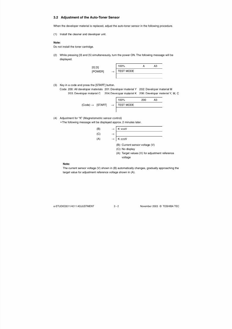
8/2/2019 ES-3511 Service Handbook
http://slidepdf.com/reader/full/es-3511-service-handbook 192/543
e-STUDIO3511/4511 ADJUSTMENT 3 - 2 November 2003 © TOSHIBA TEC
3.2 Adjustment of the Auto-Toner Sensor
When the developer material is replaced, adjust the auto-toner sensor in the following procedure.
(1) Install the cleaner and developer unit.
Note:
Do not install the toner cartridge.
(2) While pressing [0] and [5] simultaneously, turn the power ON. The following message will be
displayed.
100% A A3
TEST MODE
[0] [5]
[POWER] →
(3) Key in a code and press the [START] button.
Code 200: All developer materials 201:Developer material Y 202: Developer material M
203: Developer material C 204: Developer material K 206: Developer material Y, M, C
(4) Adjustment for “K” (Magnetometric sensor control)
• The following message will be displayed approx. 2 minutes later.
100% 200 A3
TEST MODE(Code) → [START] →
K: xxxV
K:zzzV
(B) →
(C) →
(A) →
(B): Current sensor voltage (V)
(C): No display
(A): Target values (V) for adjustment reference
voltage
Note:The current sensor voltage (V) shown in (B) automatically changes, gradually approaching the
target value for adjustment reference voltage shown in (A).

8/2/2019 ES-3511 Service Handbook
http://slidepdf.com/reader/full/es-3511-service-handbook 193/543
November 2003 © TOSHIBA TEC 3 - 3 e-STUDIO3511/4511 ADJUSTMENT
• In 30 to 60 seconds, the current sensor voltage (V) in (B) is converged. Then the sensor output
control value (bit value) corresponding to the initial developer material is displayed in (C).
(B): Current sensor voltage (V)
(C): Sensor output control value (bit value)
(A): Target value (V) for adjustment reference voltage
K: xxxV
K:yyy
K: zzzV
(B) →
(C) →
(A) →
Note:
Be careful that the values in (A), (B) and (C) vary with humidity.
• In case of single-color adjustment, press the [ENTER] button to store the adjustment results in
memory when the control value is displayed. In case of multiple-color adjustment, it is automati-
cally proceeded to the adjustment of next color.
(5) Adjustments for “Y”, “M” and “C” (light sensor control)
• In 15 to 45 seconds, the following message will be displayed (The time varies with the number
of colors to be adjusted).
(B): Current sensor voltage (V)
(C): No display
(A): Target value (V) for adjustment reference voltage
Y:
Y:
(B) →
(C) →
(A) →
Note:
The current sensor voltage (V) shown in (B) automatically changes, gradually approaching the
target value for adjustment reference voltage shown in (A).
• After approx. 5 seconds have passed, the current sensor voltage (V) in (B) is converged. Then
the sensor output control value (bit value) corresponding to the initial developer material is
displayed in (C).
(B): Current sensor voltage (V)
(C): Sensor output control value (bit value)
(A): Target value (V) for adjustment reference voltage
Y: xxxV
Y: yyy
Y: zzzV
(B) →
(C) →
(A) →
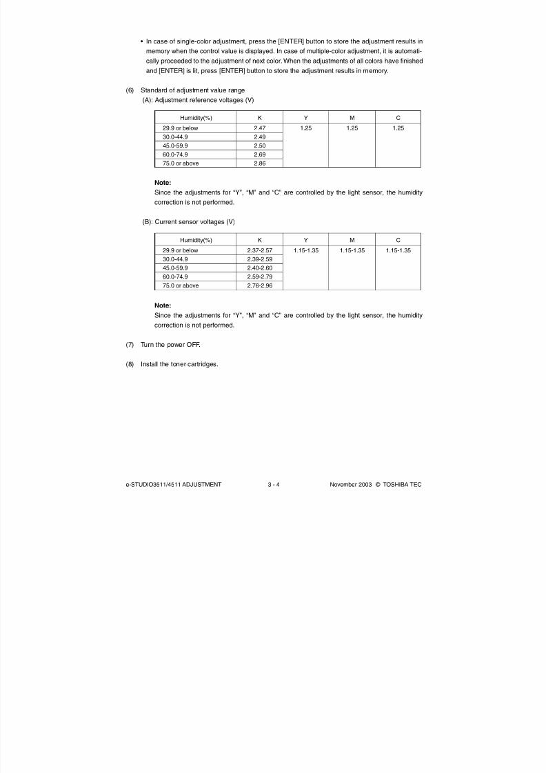
8/2/2019 ES-3511 Service Handbook
http://slidepdf.com/reader/full/es-3511-service-handbook 194/543
e-STUDIO3511/4511 ADJUSTMENT 3 - 4 November 2003 © TOSHIBA TEC
Humidity(%)
29.9 or below
30.0-44.9
45.0-59.9
60.0-74.9
75.0 or above
K
2.47
2.49
2.50
2.69
2.86
Note:
Since the adjustments for “Y”, “M” and “C” are controlled by the light sensor, the humiditycorrection is not performed.
(B): Current sensor voltages (V)
• In case of single-color adjustment, press the [ENTER] button to store the adjustment results in
memory when the control value is displayed. In case of multiple-color adjustment, it is automati-
cally proceeded to the adjustment of next color. When the adjustments of all colors have finished
and [ENTER] is lit, press [ENTER] button to store the adjustment results in memory.
(6) Standard of adjustment value range
(A): Adjustment reference voltages (V)
Y
1.25
M
1.25
C
1.25
Note:
Since the adjustments for “Y”, “M” and “C” are controlled by the light sensor, the humidity
correction is not performed.
(7) Turn the power OFF.
(8) Install the toner cartridges.
Humidity(%)
29.9 or below
30.0-44.9
45.0-59.9
60.0-74.9
75.0 or above
K
2.37-2.57
2.39-2.59
2.40-2.60
2.59-2.79
2.76-2.96
Y
1.15-1.35
M
1.15-1.35
C
1.15-1.35

8/2/2019 ES-3511 Service Handbook
http://slidepdf.com/reader/full/es-3511-service-handbook 195/543
November 2003 © TOSHIBA TEC 3 - 5 e-STUDIO3511/4511 ADJUSTMENT
3.3 Performing Image Quality Control
(1) When unpacking
Prior to image dimensional adjustment, perform the “Automatic initialization of image quality
control (05-396)” procedure.
(2) When any of the following parts is replaced, be sure to perform the “Automatic initialization of
image quality control (05-396)” procedure.
• Photoconductive drum • Developer material • Laser optical unit
• Image quality sensor • Transfer belt • 1st transfer roller
• 2nd transfer roller • Main charger • Main charger grid
• Drum cleaning blade • Drum cleaner brush
Note:
When performing "Automatic gamma adjustment" in addition, “Automatic initialization of image
quality control (05-396)” should be done first.
(3) When performing "Automatic gamma adjustment" in cases no parts written above are replaced,
do the “Forced performing of image quality closed-loop control (05-395)” procedure before
"Automatic gamma adjustment".
Code
395
396
Contents
<Procedure>
(1) While pressing [0] and [5] simultaneously, turn the power ON.
→ Adjustment Mode
(2) Key in [395] and press the [START] button.
(3) "WAIT" is displayed.(4) When the adjustment finishes normally, the equipment
returns to the initial state of Adjustment Mode.
If an error has occurred, take appropriate action by referring
to “5. TROUBLESHOOTING”.
<Procedure>
(1) While pressing [0] and [5] simultaneously, turn the power ON.
→ Adjustment Mode
(2) Key in [396] and press the [START] button.
(3) "WAIT" is displayed.
(4) When the adjustment finishes normally, the equipment will
return to initial state of the Adjustment Mode.If an error has occurred, take appropriate action by referring
to “5. TROUBLESHOOTING”.
Item to be adjusted
Forced performing of
image quality closed-loop
control
Automatic initialization of
image quality control
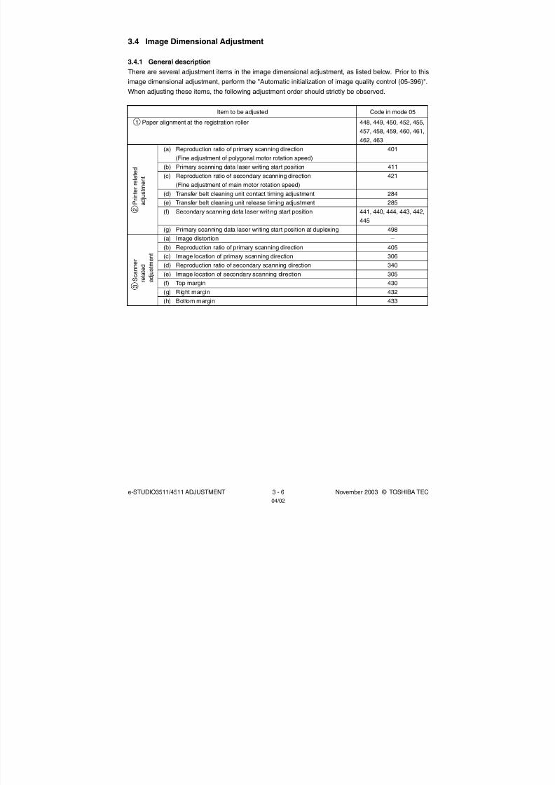
8/2/2019 ES-3511 Service Handbook
http://slidepdf.com/reader/full/es-3511-service-handbook 196/543
e-STUDIO3511/4511 ADJUSTMENT 3 - 6 November 2003 © TOSHIBA TEC
3.4 Image Dimensional Adjustment
3.4.1 General description
There are several adjustment items in the image dimensional adjustment, as listed below. Prior to this
image dimensional adjustment, perform the "Automatic initialization of image quality control (05-396)".
When adjusting these items, the following adjustment order should strictly be observed.
Item to be adjusted
1 Paper alignment at the registration roller
(a) Reproduction ratio of primary scanning direction
(Fine adjustment of polygonal motor rotation speed)
(b) Primary scanning data laser writing start position
(c) Reproduction ratio of secondary scanning direction
(Fine adjustment of main motor rotation speed)
(d) Transfer belt cleaning unit contact timing adjustment(e) Transfer belt cleaning unit release timing adjustment
(f) Secondary scanning data laser writing start position
(g) Primary scanning data laser writing start position at duplexing
(a) Image distortion
(b) Reproduction ratio of primary scanning direction
(c) Image location of primary scanning direction
(d) Reproduction ratio of secondary scanning direction
(e) Image location of secondary scanning direction
(f) Top margin
(g) Right margin(h) Bottom margin
Code in mode 05
448, 449, 450, 452, 455,
457, 458, 459, 460, 461,
462, 463
401
411
421
284285
441, 440, 444, 443, 442,
445
498
–
405
306
340
305
430
432433
2
P r i n
t e r r e l a t e d
a d j u
s t m e n t
3
S c a n n e r
r e l a t e d
a d j u s t m e n t
04/02

8/2/2019 ES-3511 Service Handbook
http://slidepdf.com/reader/full/es-3511-service-handbook 197/543
November 2003 © TOSHIBA TEC 3 - 7 e-STUDIO3511/4511 ADJUSTMENT
[Procedure to key in adjustment values]
In accordance with the procedure described below, make adjustment of each adjustment item so that
the measured values obtained from test copies satisfy the specification. By pressing the [FAX] button,
immediately after starting the Adjustment Mode (05), single-sided test copying can be performed
(normal copy mode).
0
1
5
POWER
ENTER
INTERRUPT
FAX
Digital keys
START
: Key in codes.
<Operation keys> <Display>Varies with the code “XXX” keyed in.
Current adjustment value
Adjustment value newly keyed in.
(If no entering, YYY is displayed.)
Power OFF/ON : Exit the Adjustment Mode.
Test copy
Digital keys
START
: Key in adjustment
values.
Value ZZZ is stored
replacing values YYY.
If the test copy does not
satisfy the specified values,
return to step 1 and
repeat the adjustment
procedure.
or
( CLEAR Use to make corrections)
100% A A3
TEST MODE
100% A A3
TEST MODE
100% A A3
Wait Warming Up
100% A A3
COPYING
Code No.
100%
YYY ZZZ
XXX A3
TEST MODE

8/2/2019 ES-3511 Service Handbook
http://slidepdf.com/reader/full/es-3511-service-handbook 198/543
e-STUDIO3511/4511 ADJUSTMENT 3 - 8 November 2003 © TOSHIBA TEC
( )
3.4.2 Paper alignment at the registration roller
The aligning amount is adjusted by using the following codes in Adjustment Mode (05).
Sub-code
(*1) 0: Long size 1: Middle size 2: Short size
(*2) 0: Long size 1: Middle size 2: Short size 3: Post card
(*3) 0: Long size of thick paper 2 1: Middle size of thick paper 2
2: Short size of thick paper 2 3: Long size of thick paper 3
4: Middle size of thick paper 3 5: Short size of thick paper 3
6: Long size of OHP film 7: Middle size of OHP film
8: Short size of OHP film 9: Post card
(*4) 0: Long size 1: Middle size 2: Short size 1 3: Short size 2
Notes:
1. Long size: 330 mm or longer (13.0 inches or longer)
Middle size: 220-329 mm (8.7-12.9 inches)
Short size: 219 mm or shorter (8.6 inches or shorter)
Short size 1: 205-219 mm (8.1-8.6 inches or shorter)
Short size 2: 204 mm or shorter (8.0 inches or shorter)
2. The adjustment of “Post card” is for Japan only.
<Procedure>
Paper
type
Plain
paper
Thick
paper 1
Thick
paper 2
Thick
paper 3
OHP film
Weight
64-80 g/m2
17-20 lb.
81-105 g/m2
21-28 lb.
106-163 g/m2
29-43 lb.
164-209 g/m2
44-55 lb.
-
Upper
drawer
450 (*4)
469 (*4)
-
-
-
Lower
drawer
452 (*4)
470 (*4)
-
-
-
PFP upper
drawer
448 (*4)
471 (*4)
-
-
-
PFP lower
drawer
449 (*4)
472 (*4)
-
-
-
LCF
457
473
-
-
-
ADU
455 (*1)
474 (*1)
-
-
-
Bypass feed
Black Color
458 (*1)
460 (*1)
461 (*1) 475 (*3)
462 (*2) 475 (*3)
463 (*1) 475 (*3)
[0] [5]
[Power]
Current valuedisplayed
Enter new
value
[POWER]
OFF/ON
(Exit)
(Not necessary for LCF)
[Drawer selection](*5) + [FAX]
(Test print)
[SET] or
[INTERRUPT]
Stores in memory
[START](Code) (Sub-code) [START] ( )
04/05
8/2/2019 ES-3511 Service Handbook
http://slidepdf.com/reader/full/es-3511-service-handbook 199/543
November 2003 © TOSHIBA TEC 3 - 9 e-STUDIO3511/4511 ADJUSTMENT
(*5) 1: Single-sided grid pattern in Black Mode
3: Double-sided grid pattern in Black Mode
55: Grid pattern of thick paper 2 in Full Color Mode
56: Grid pattern of thick paper 3 in Full Color Mode
57: Grid pattern of OHP film in Full Color Mode
58: Single-sided grid pattern of thick paper 2 in Black Mode
59: Single-sided grid pattern of thick paper 3 in Black Mode
60: Single-sided grid pattern of OHP film in Black Mode
Note:
If the aligning amount is too large, abnormal noise (paper-folding noise) or actual paper folding may
occur during paper feeding. If the aligning amount is too small, on the other hand, a skew, an image
dislocation in feeding direction or a paper exit jam (E010) may occur. Pay attention to the above
and select the appropriate value.

8/2/2019 ES-3511 Service Handbook
http://slidepdf.com/reader/full/es-3511-service-handbook 200/543
e-STUDIO3511/4511 ADJUSTMENT 3 - 10 November 2003 © TOSHIBA TEC
3.4.3 Printer related adjustment
(a) Reproduction ratio of primary scanning direction (Fine adjustment of polygonal motor
rotation speed (Printer))
1. While pressing [0] and [5] simultaneously, turn the power ON. → (Adjustment Mode)
2. Press [1]→ [FAX]. (A grid pattern with 10 mm squares is printed out. Use A3/LD from the
lower drawer.)
3. Measure the distance A from the 1st line to the 21st line of the grid pattern.
4. Check if the distance A is within 200±0.5 mm.
5. If not, use the following procedure to change values and measure the distance A again.
<Procedure> (Adjustment Mode)→ (Key in the code [401]) → [START]
→ (Key in a value (acceptable values: 0 to 255))
→ [ENTER] or [INTERRUPT] (Stored in memory)
→ "100% A" is displayed.
→ Press [1]→ [FAX]→ (A grid pattern is printed out.)
** The larger the adjustment value is, the longer the distance A becomes (approx.
0.05 mm/step).
(b) Primary scanning data laser writing start position (Printer)
1. While pressing [0] and [5] simultaneously, turn the power ON.→ (Adjustment Mode)
2. Press [1]→ [FAX]. (A grid pattern with 10 mm squares is printed out. Use A3/LD from the lower
drawer.)
3. Measure the distance B from the left edge of the paper to the 6th line of the grid pattern.
4. Check if the distance B is within 52±0.5 mm.
5. If not, use the following procedure to change values and measure the distance B again.
<Procedure> (Adjustment Mode)→ (Key in the code [411]) → [START]
→ (Key in a value (acceptable values: 0 to 255))
→ [ENTER] or [INTERRUPT] (Stored in memory)
→ "100% A" is displayed
→ Press [1]→ [FAX]→ (A grid pattern is printed out.)
* The larger the adjustment value is, the longer the distance B becomes (approx.
0.04 mm/step).
6. After the adjustment for the code 411 is completed, apply the same adjustment value for the
code 410.
<Procedure> (Adjustment Mode)→ (Key in the code [410]) → [START]
→ (Key in the same value in the step 5 above)
→ [ENTER] or [INTERRUPT] (Stored in memory)
Note:
Make sure the 1st line of the grid pattern is printed out since the line is occasionally vanished.
04/09

8/2/2019 ES-3511 Service Handbook
http://slidepdf.com/reader/full/es-3511-service-handbook 201/543
November 2003 © TOSHIBA TEC 3 - 11 e-STUDIO3511/4511 ADJUSTMENT04/09
(c) Reproduction ratio of secondary scanning direction (Fine adjustment of main motor rotation
speed (Printer))
1. While pressing [0] and [5] simultaneously, turn the power ON. → (Adjustment Mode)
2. Press [1] → [FAX]. (A grid pattern with 10mm squares is printed out. Use A3/LD from the lower
drawer.)
3. Measure the distance C from the 2nd line at the leading edge of the paper to the 22nd line of
the grid pattern.
* Normally, the 1st line of the grid pattern is not printed.
4. Check if the distance C is within 200±0.5 mm.
5. If not, use the following procedure to change values and measure the distance C again.
<Procedure> (Adjustment Mode) → (Key in the code [426]) → [START]
* Confirm that the input value is [153]. If not, key in [153].
→ (Key in [153])
→ [ENTER] or [INTERRUPT] (Stored in memory)
→ (Key in the code [421]) → [START]
→ (Key in a value (recommended values: 110 to 140 / acceptable values: 0 to 255))→ [ENTER] or [INTERRUPT] (Stored in memory)
* When the value is not within the recommended values, the trailing edge area of
the image may be out of position for the paper length or the density at the trailing
edge area of the image may become lower. Perform the adjustment confirming
the image.
→ “100% A” is displayed
→ Press [1]→ [FAX]→ (A grid pattern is printed out.)
** The larger the adjustment value is, the longer the distance C becomes
(approx. 0.5 mm/6 steps).
(d) Transfer belt cleaning unit contact timing adjustment
This adjustment has to be performed after “Adjustment of secondary scanning direction reproduction
ratio (421)”. Acceptable values are 88 to 168. The larger the value is, the later the transfer belt
cleaning unit contact timing becomes.
1. While pressing [0] and [5] simultaneously, turn the power ON.→ (Adjustment Mode)
2. According to the input value for “Adjustment of secondary scanning direction reproduction ratio
(421)”, key in the value shown in the following table.
* Be sure to key in the correct value because incorrect value may reduce the cleaning efficiency of
the transfer belt.
Adjustment (code)
Adjustment of secondary scanning direction
reproduction ratio (421)
Transfer belt cleaning unit contact timing
adjustment (284)
110
147
111-120
143
121-130
141
131-140
137
Input value
<Procedure> (Adjustment Mode) → (Key in the code [284]) → [START]
→ (Key in a value)
→ [ENTER] or [INTERRUPT] (Stored in memory)

8/2/2019 ES-3511 Service Handbook
http://slidepdf.com/reader/full/es-3511-service-handbook 202/543
e-STUDIO3511/4511 ADJUSTMENT 3 - 12 November 2003 © TOSHIBA TEC
Code
441
440444/443
442
445
Order for
adjustment
1
23
4
5
Paper
source
Lower drawer
Upper drawerPFP or LCF
Bypass feed
Duplexing
Acceptable
value
0 to 80
0 to 400 to 40
0 to 40
0 to 40
Paper
size
A3/LD
A4/LTA4/LT
A4/LT
A3/LD
Remarks
Paper fed from the lower drawer
1. While pressing [0] and [5] simultaneously, turn the power ON. → (Adjustment Mode)
2. Press [1] ([3] for duplexing)→ [FAX]. (A grid pattern with 10mm squares is printed out.)
3. Measure the distance D from the leading edge of the paper to the 6th line of the grid pattern.
* Normally, the 1st line of the grid pattern is not printed.
* At the duplexing, measure it on the top side of the grid pattern.
4. Check if the distance D is within 52±0.5 mm.
5. If not, use the following procedure to change values and measure the distance D again.
<Procedure> (Adjustment Mode) → (Key in the code shown above) → [START]
→ (Key in an acceptable value shown above)
→ [ENTER] or [INTERRUPT] (Stored in memory)
→ "100% A" is displayed
→ Press [1] ([3] for duplexing)
→ [FAX]→ (A grid pattern is printed out.)
* The larger the adjustment value is, the longer the distance D becomes (approx.
0.2 mm/step).
(e) Transfer belt cleaning unit release timing adjustment
This adjustment has to be performed after “Adjustment of secondary scanning direction reproduction
ratio (421)” Acceptable values are 88 to 168. The larger the value is, the later the transfer belt
cleaning unit release timing becomes.
1. While pressing [0] and [5] simultaneously, turn the power ON.→ (Adjustment Mode)
2. According to the input value for “Adjustment of secondary scanning direction reproduction ratio
(421)”, key in the value shown in the following table.
* Be sure to key in the correct value because incorrect value may reduce the cleaning efficiency of
the transfer belt.
Adjustment (code)
Adjustment of secondary scanning direction
reproduction ratio (421)
Transfer belt cleaning unit release timing
adjustment (285)
110
147
111-120
143
121-130
141
131-140
137
Input value
<Procedure> (Adjustment Mode)→ (Key in the code [285]) → [START]
→ (Key in a value)→ [ENTER] or [INTERRUPT] (Stored in memory)
(f) Secondary scanning data laser writing start position
This adjustment has to be performed for each paper source.
The following table shows the order of the paper source to be adjusted, code, paper size and
acceptable values.
04/09

8/2/2019 ES-3511 Service Handbook
http://slidepdf.com/reader/full/es-3511-service-handbook 203/543
November 2003 © TOSHIBA TEC 3 - 13 e-STUDIO3511/4511 ADJUSTMENT
(g) Primary scanning data laser writing start position at duplexing
Note:
Make sure the first line of the grid pattern is printed out since the line is occasionally vanished.
(g-1) Adjustment for long-sized paper
1. While pressing [0] and [5] simultaneously, turn the power ON. → (Adjustment Mode)
2. Press [3]→ [FAX]. (A grid pattern with 10 mm squares is printed out. Use A3/LD from the lower
drawer.)
3. Check the grid pattern on the test print and measure the distance E from the left edge of the
paper to the 6th line of the grid pattern.
4. Check if the distance E is within 52±0.5 mm.
5. If not, use the following procedure to change values and measure the distance E again.
<Procedure> (Adjustment Mode) → (Key in the code [498]) → [START]→ [0] → [START]
→ (Key in a value (acceptable values: 0 to 255))
→ [ENTER] or [INTERRUPT] (Stored in memory)
→ "100% A" is displayed.
→ Press [3]→ [FAX]→ (A grid pattern is printed out.)
** The larger the adjustment value is, the longer the distance E becomes (approx.
0.04 mm/step).
(g-2) Adjustment for short-sized paper
1. While pressing [0] and [5] simultaneously, turn the power ON. → (Adjustment Mode)
2. Press [3]→ [FAX]. (A grid pattern with 10 mm squares is printed out. Use A4/LT from the upper
drawer.)
3. Check the grid pattern on the test print and measure the distance E from the left edge of the
paper to the 6th line of the grid pattern.
4. Check if the distance E is within 52±0.5 mm.
5. If not, use the following procedure to change values and measure the distance E again.
<Procedure> (Adjustment Mode)→ (Key in the code [498]) → [START]→ [1]→ [START]
→ (Key in a value (acceptable values: 0 to 255))
→ [ENTER] or [INTERRUPT] (Stored in memory)
→ "100% A" is displayed
→ Press [3]→ [FAX]→ (A grid pattern is printed out.)
* The larger the adjustment value is, the longer the distance E becomes (approx.
0.04 mm/step).
04/02

8/2/2019 ES-3511 Service Handbook
http://slidepdf.com/reader/full/es-3511-service-handbook 204/543
e-STUDIO3511/4511 ADJUSTMENT 3 - 14 November 2003 © TOSHIBA TEC
A21
6
1
B, E
D
C
6
2
2 2
F e e d i n g d i r e c t i o n
[Grid pattern]
Fig. 3-401
<Adjustment order>
[0] [5] [Power ON]→ [1] ([3](05-445, 498) for duplexing) → [FAX]
A: 05-401 (Lower drawer, A3/LD) → 200±0.5 mm (0.05 mm/step)
B: 05-411 (Lower drawer, A3/LD) → 52±0.5 mm (0.04 mm/step)
→ Key in the same value for 05-410.C: 05-421 (Lower drawer, A3/LD) → 200±0.5 mm (0.5 mm/6 steps)
D: 05-440 (Upper drawer, A4/LT) → 52±0.5 mm (0.2 mm/step),
441 (Lower drawer, A3/LD),
442 (Bypass feed, A4/LT),
443 (LCF, A4/LT), 444 (PFP, A4/LT),
445 (Duplexing, A3/LD)
E: 05-498-0 (Lower drawer, A3/LD), → 52±0.5 mm (0.04 mm/step)
498-1 (Upper drawer, A4/LT)
04/09

8/2/2019 ES-3511 Service Handbook
http://slidepdf.com/reader/full/es-3511-service-handbook 205/543
November 2003 © TOSHIBA TEC 3 - 15 e-STUDIO3511/4511 ADJUSTMENT
3.4.4 Scanner related adjustment
(a) Image distortion
1. While pressing [0] and [5] simultaneously, turn
the power ON.
2. Press [FAX] to make a copy of any image on a
sheet of A3/LD paper.
3. Key in [308] and press the [START] button to
move the carriage to the adjustment position.
4. Make an adjustment in the order of step 1 and 2.
Step 1
In case of A:
Tighten the mirror-3 adjustment screw (CW).
In case of B:
Loosen the mirror-3 adjustment screw (CCW).
Step 2
In case of C:Tighten the mirror-1 adjustment screw (CW).
In case of D:
Loosen the mirror-1 adjustment screw (CCW).
5. Apply the screw locking agents to the adjustment
screws. (2 areas)
- Recommended screw lock agent
Manufacturer: Three Bond
Product name: 1401E
A B
Feeding direction
Feeding direction
Step 1
Step 2
C D
Adjustment screw for the mirror-3
(Rear)
Carriage-2
Adjustment screw for the mirror-1
(Rear)
Carriage-1
Fig. 3-402
Fig. 3-403
Fig. 3-404
04/09

8/2/2019 ES-3511 Service Handbook
http://slidepdf.com/reader/full/es-3511-service-handbook 206/543
e-STUDIO3511/4511 ADJUSTMENT 3 - 16 November 2003 © TOSHIBA TEC
The following adjustments (b) to (e) should be performed with Test Chart No. TCC-1. (Refer to page 3-19.)
(b) Reproduction ratio adjustment of primary scanning direction
1. While pressing [0] and [5] simultaneously, turn the power ON.→ (Adjustment Mode)
2. Place Test Chart No. TCC-1 on the original glass (with the arrow positioned at the left rear side).
3. Press [FAX]→ [START] to make a copy at the mode of A4/LT, 100%, Black and Text/Photo.
4. Measure the distance A between M1 and M2 on the copy with a ruler.
5. Check if the distance A is within 200±0.5 mm.
6. If not, use the following procedure to change values and repeat step 3. to 5. above.
<Procedure> (Adjustment Mode)→ (Key in the code [405]) → [START]
→ (Key in a value (acceptable values : 0 to 255) with digital keys)
→ [ENTER] or [INTERRUPT] (Stored in memory)
* The larger the adjustment value is, the longer the distance A becomes (approx.
0.1 mm/step).
(c) Image location of primary scanning direction
1. While pressing [0] and [5] simultaneously, turn the power ON.→ (Adjustment Mode)
2. Place Test Chart No. TCC-1 on the original glass (with the arrow positioned at the left rear side).
3. Press [FAX]→ [START] to make a copy at the mode of A4/LT, 100%, Black and Text/Photo.
4. Measure the distance B from the left paper edge to the 5 mm line of left grid pattern on the
copy with a ruler.
5. Check if the distance B is within 5±0.5 mm.
6. If not, use the following procedure to change values and repeat step 3. to 5. above.
<Procedure> (Adjustment Mode)→ (Key in code [306]) → [START]
→ (Key in a value (acceptable values : 0 to 255))
→ [ENTER] or [INTERRUPT] (Stored in memory)
* The larger the adjustment value is, the longer the distance B becomes (approx.
0.04 mm/step).
(d) Reproduction ratio of secondary scanning direction
1. While pressing [0] and [5] simultaneously, turn the power ON.→ (Adjustment Mode)
2. Place Test Chart No. TCC-1 on the original glass (with the arrow positioned at the left rear side).
3. Press [FAX]→ [START] to make a copy at the mode of A4/LT, 100%, Black and Text/Photo.
4. Measure the distance C between M3 and M4 on the copy with a ruler.
5. Check if the distance C is within 150±0.5 mm.
6. If not, use the following procedure to change values and repeat step 3. to 5. above.
<Procedure> (Adjustment Mode)→ (Key in the code [340]) → [START]
→ (Key in a value (acceptable values : 0 to 255))
→ [ENTER] or [INTERRUPT] (Stored in memory)
* The larger the adjustment value is, the longer the distance C becomes (approx.
0.3 mm/step).

8/2/2019 ES-3511 Service Handbook
http://slidepdf.com/reader/full/es-3511-service-handbook 207/543
November 2003 © TOSHIBA TEC 3 - 17 e-STUDIO3511/4511 ADJUSTMENT
(e) Image location of secondary scanning direction
1. While pressing [0] and [5] simultaneously, turn the power ON.→ (Adjustment Mode)
2. Place Test Chart No. TCC-1 on the original glass (with the arrow positioned at the left rear
side).
3. Press [FAX] → [START] to make a copy at the mode of A4/LT, 100%, Black and Text/Photo.
4. Measure the distance D from the top paper edge to the 10 mm line of top grid pattern on the
copy with a ruler.
5. Check if the distance D is within 10±0.5 mm.
6. If not, use the following procedure to change values and repeat step 3. to 5. above.
<Procedure> (Adjustment Mode) → (Key in the code [305]) → [START]
→ (Key in a value (acceptable values : 92 to 164))
→ [ENTER] or [INTERRUPT] (Stored in memory)
* The larger the adjustment value is, the longer the distance D becomes (approx.
0.14 mm/step).
(f) Top margin
1. While pressing [0] and [5] simultaneously, turn the power ON.→ (Adjustment Mode)
2. Open the platen cover or RADF.
3. Press [FAX] → [START] to make a copy at the mode of A3/LD, 100%, Black, Text/Photo and
lower drawer.
4. Measure the blank area E at the leading edge of the copied image.
5. Check if the blank area E is within the range of 3±0.5 mm.
6. If not, use the following procedure to change values and repeat the steps 3. to 5. above.
<Procedure> (Adjustment Mode) → (Key in the code [430]) → [START]
→ (Key in a value (acceptable values : 0 to 255))
→ [ENTER] or [INTERRUPT] (Stored in memory)
→ (“100% A” is displayed.)
* The larger the adjustment value is, the wider the blank area becomes (approx.
0.04 mm/step).
E
Feeding direction
Fig. 3-405

8/2/2019 ES-3511 Service Handbook
http://slidepdf.com/reader/full/es-3511-service-handbook 208/543
e-STUDIO3511/4511 ADJUSTMENT 3 - 18 November 2003 © TOSHIBA TEC
(h) Bottom margin
1. While pressing [0] and [5] simultaneously, turn the power ON.→ (Adjustment Mode)
2. Open platen cover or RADF.
3. Press the [FAX] → [START] to make a copy at the mode of A3/LD, 100%, Black, Text/Photo
and lower drawer.
4. Measure the blank area G at the trailing edge of the copied image.
5. Check if the blank area G is within the range of 2±0.5 mm.
6. If not, use the following procedure to change values and repeat the steps 2. to 4. above.
<Procedure> (Adjustment Mode)→ (Key in the code [433]) → [START]
→ (Key in value (acceptable values : 0 to 255))
→ [ENTER] or [INTERRUPT] (stored in memory)
→ (“100% A” is displayed.)
* The larger the adjustment value is, the wider the blank area at the trailing edge
becomes (approx. 0.04 mm/step).
Feeding direction
G
Fig. 3-407
(g) Right margin
1. While pressing [0] and [5] simultaneously, turn the power ON.→ (Adjustment Mode)
2. Open the platen cover or RADF.
3. Press [FAX]→ [START] to make a copy at the mode of A3/LD, 100%, Black, Text/Photo and
lower drawer.
4. Measure the blank area F at the right side of the copied image.
5. Check if the blank area F is within the range of 2+1 mm, 2-0.5 mm.6. If not, use the following procedure to change values and repeat the steps 3. to 5. above.
<Procedure> (Adjustment Mode)→ (Key in the code [432]) → [START]
→ (Key in a value (acceptable values : 0 to 255))
→ [ENTER] or [INTERRUPT] (Stored in memory).
→ (“100% A” is displayed.)
* The larger the adjustment value is, the wider the blank area at the right side
becomes (approx. 0.04 mm/step).
F
Feeding direction
Fig. 3-406

8/2/2019 ES-3511 Service Handbook
http://slidepdf.com/reader/full/es-3511-service-handbook 209/543
November 2003 © TOSHIBA TEC 3 - 19 e-STUDIO3511/4511 ADJUSTMENT
C
D
B
A
Fig. 3-408 Chart TCC-1
<Adjustment order>
[0] [5] [Power ON] → (Chart TCC-1) → [FAX] → [START] (A4/LT, 100%, Black and Text/Photo)
A: 05-405→ 200±0.5 mm (0.1 mm/step)
B: 05-306→ 5±0.5 mm (0.04 mm/step)
C: 05-340→ 150±0.5 mm (0.3 mm/step)
D: 05-305→ 10±0.5 mm (0.14 mm/step)
F e e d i n g d i r e c t i o n

8/2/2019 ES-3511 Service Handbook
http://slidepdf.com/reader/full/es-3511-service-handbook 210/543
e-STUDIO3511/4511 ADJUSTMENT 3 - 20 November 2003 © TOSHIBA TEC
[1]
[2] [2][3] [3]
[3]
[4]
[5]
[6] [6]
[8]
[8][9][10]
[11]
[12]
[13]
[14]
[7]
[7]
[7][7]
TOSHIBA COLOR CHARTNo.TCC-1
[2]
[2]
[1]
[1]
[1]
Fig. 3-409
[1] Grid patterns : For adjusting margin (void) and scanner section
[2] YMCK patches : For checking uniformity
[3] Resolution patterns : For checking resolution
[4] Gradation pattern : Gradation pattern of seven colors (Y, M, C, R, G, B and K)
Coverage: 10-100%
For adjusting the halftone reproduction and gray balance
[5] Color registration pattern : For checking color registration
[6] Pictures : For checking color reproduction and moire
[7] Magnification lines : For checking the magnification error of primary and
secondary scanning directions
[8] Center lines : Center lines for A4/LT sizes
[9] Arrow : A mark for placing the chart properly onto the original glass(place it to the left rear corner of the original glass.)
[10] Halftone band : For checking uniformity
[11] White text on the black solid : For checking the reproduction of white text on black solid
[12] Text : For checking reproduction of text
[13] Thin lines : For checking reproduction of the thin lines (line width:
100µm)
[14] Note area : For recording the date, conditions, etc.

8/2/2019 ES-3511 Service Handbook
http://slidepdf.com/reader/full/es-3511-service-handbook 211/543
November 2003 © TOSHIBA TEC 3 - 21 e-STUDIO3511/4511 ADJUSTMENT
(2) When any of the following parts are replaced or adjusted, make a copy and check the image to
determine if adjustment is necessary:
• 2nd transfer roller
Notes:
1. Be sure that this adjustment be made after performing the image adjustment in "3.3 Adjust-
ment of Image Quality Control" and "3.4 Image Dimensional Adjustment".
2. Normally, only the adjustment of color/black integrated pattern is needed. When the adjust-
ment of "3.5.12 Beam level conversion setting" is made, color pattern and black pattern need
to be adjusted individually.
Contents
<Procedure>
(1) While pressing [0] and [5] simultaneously, turn the power ON.→
Adjustment Mode
(2) Select the A4/LT drawer. Key in the pattern number and press the
[FAX] button to output a “Patch chart for gamma adjustment”.
Pattern No. Pattern Remarks
4 Color/black integrated When performing code 164210* Black When performing code 580
5* Color When performing code 1643
* This adjustment is performed only when "3.5.12 Beam level
conversion setting" is performed. Usually, only the adjustment
with the color/black integrated pattern (05-1642) is performed.
(3) Place the patch chart for adjustment printed in step (2) face down
on the original glass. In the cases of patterns 4 and 5, place the
chart aligning its side with 2 black squares against the original scale.
In the case of pattern 10, place the chart aligning its black side of
the gradation pattern against the original scale.
(4) Key in a code and press the [START] button.
→ The scanner reads the chart automatically and performs
automatic gamma adjustment calculation (approx. 30 sec.).
(5) When the adjustment has finished normally, “ENTER” is shown. Press the
[ENTER] button to have the adjustment results reflected.
(To cancel the reflection of adjustment results, press the [CANCEL] button.)
In the case of an abnormal ending, “ADJUSTMENT ERROR” is shown.
Press the [CANCEL] button to clear the error display. When it is cleared,
the control panel display will return to the ready state. Then, check if the
patch chart on the original glass is placed in the wrong direction or if it is
placed inclined on the original glass, and then repeat step (3) and after-
ward.
3.5 Image Quality Adjustment (Copying Function)
Item to be adjusted
Automatic gamma
adjustment
Code
1642
(1643)
(580)
<Adjustment Mode (05)>
3.5.1 Automatic gamma adjustment
When the reproduction of gradation is not appropriate, the gradation reproducibility of all colors Y, M, C
and K can be corrected by performing this automatic gamma adjustment. In case the gradation
reproduction of the image checked is not satisfactory, make this adjustment as described below at parts
replacement.
(1) When unpacking or any of the following parts has been or replaced, be sure to make this adjustment:• Laser optical unit • Photoconductive drum • Developer material
• Main charger wire • Main charger grid • Transfer belt
• 1st transfer roller • Drum cleaning blade • Drum cleaner brush
• Image guality sensor
04/05

8/2/2019 ES-3511 Service Handbook
http://slidepdf.com/reader/full/es-3511-service-handbook 212/543
e-STUDIO3511/4511 ADJUSTMENT 3 - 22 November 2003 © TOSHIBA TEC
Text/Photo
503
508
505
514
Text
504
510
507
515
Printed Image
1552
1562
1572
1582
Photo
1553
1563
1573
1583
Map
1554
1564
1574
1584
Text/Photo
1550
1560
1570
1580
Text
1551
1561
1571
1581
3.5.2 Density adjustment
The center density and the density variation controlled by density adjustment keys can be adjusted as
follows.
Make a test copy and compare the image obtained with the current settings; if necessary, make
adjustment using the following procedure.
F u l l C o l o r
Color
modeRemarks
The larger the value is, the
darker the image becomes.
Acceptable values: 0 to 255
(Default: 128)
The larger the value is, the
darker the dark side becomes.
Acceptable values: 0 to 255
(Default: 20)
The larger the value is, the
lighter the light side becomes.
Acceptable values: 0 to 255
(Default: 20)
The larger the value is, the
darker the image becomes.
Acceptable values: 0 to 255
(Default: 128)
Item to be
adjusted
Manual density mode
center value
Manual density mode
dark step value
Manual density mode
light step value
Automatic density
mode
B l a c k
Color
mode
Original modeRemarks
The larger the value is, the
darker the image becomes.
Acceptable values: 0 to 255
(Default: 128)
The larger the value is, the
darker the dark side becomes.
Acceptable values: 0 to 255
(Default: 20)
The larger the value is, the
lighter the light side becomes.
Acceptable values: 0 to 255
(Default: 20)
The larger the value is, the
darker the image becomes.
Acceptable values: 0 to 255
(Default: 128)
Item to be
adjusted
Manual density mode
center value
Manual density mode
dark step value
Manual density mode
light step value
Automatic density
mode
Photo
501
509
506
512
<Adjustment Mode (05)>
Original mode
<Adjustment Mode (05)>

8/2/2019 ES-3511 Service Handbook
http://slidepdf.com/reader/full/es-3511-service-handbook 213/543
November 2003 © TOSHIBA TEC 3 - 23 e-STUDIO3511/4511 ADJUSTMENT
Note:
Be sure that this adjustment be made after performing "3.5.1 Automatic gamma adjustment".
<Procedure>
(1) While pressing [0] and [5] simultaneously, turn the power ON.
(2) Key in a code and press the [START] button.
(3) Key in an adjustment value (acceptable values: 0 to 255).
(To correct the value once keyed in , press the [CLEAR] button.)
(4) Press the [ENTER] or [INTERRUPT] button to store the value.→ The equipment goes back to
the ready state.
(5) Press the [FAX] button and then press the [START] button to make a test copy.
(6) If the desired image has not been attained, repeat step (2) to (5).

8/2/2019 ES-3511 Service Handbook
http://slidepdf.com/reader/full/es-3511-service-handbook 214/543
e-STUDIO3511/4511 ADJUSTMENT 3 - 24 November 2003 © TOSHIBA TEC
Text/Photo
1779-0
1779-1
1779-2
1784-0
1784-1
1784-2
1789-0
1789-1
1789-2
1794-0
1794-1
1794-2
3.5.3 Color balance adjustment
The color balance is adjusted by adjusting the density of each color at the Full Color Mode. The adjustment
is performed by selecting its density area from the following: low density, medium density and high
density.
Make a test copy and compare the image obtained with the current settings; if necessary, make
adjustment using the following procedure.
Note:
Be sure that this adjustment be made after performing “3.5.1 Automatic gamma adjustment”.
<Procedure>
(1) While pressing [0] and [5] simultaneously, turn the power ON.
(2) Key in the code of the mode to be adjusted (color and original mode) and press the [START]
button.
(3) Select the density area to be adjusted with digital keys (0, 1 or 2), and press the [START] button.
0 : Low density (L) 1 : Medium density (M) 2 : High density (H)
(4) Key in an adjustment value.
(To correct the value once keyed in, press the [CLEAR] button.)
(5) Press the [ENTER] or [INTERRUPT] button to store the value in memory.→ The equipment goes
back to the ready state.
(6) For resetting the value, repeat step (2) to (5).
(7) Press the [FAX] button and then press the [START] button to make a test copy.
(8) If the desired image has not been attained, repeat step (2) to (7).
Color
Yellow
Magenta
Cyan
Black
Original mode
Remarks
The larger the value is,
the darker the color to be
adjusted becomes.
Acceptable values: 0 to
255. (Default: 128)
Item to be
adjusted
Low density
Medium density
High density
Low density
Medium density
High density
Low density
Medium density
High density
Low density
Medium density
High density
Text
1780-0
1780-1
1780-2
1785-0
1785-1
1785-2
1790-0
1790-1
1790-2
1795-0
1795-1
1795-2
Printed Image
1781-0
1781-1
1781-2
1786-0
1786-1
1786-2
1791-0
1791-1
1791-2
1796-0
1796-1
1796-2
Photo
1782-0
1782-1
1782-2
1787-0
1787-1
1787-2
1792-0
1792-1
1792-2
1798-0
1798-1
1798-2
Map
1783-0
1783-1
1783-2
1788-0
1788-1
1788-2
1793-0
1793-1
1793-2
1798-0
1798-1
1798-2
<Adjustment Mode (05)>

8/2/2019 ES-3511 Service Handbook
http://slidepdf.com/reader/full/es-3511-service-handbook 215/543
November 2003 © TOSHIBA TEC 3 - 25 e-STUDIO3511/4511 ADJUSTMENT
Text/Photo
590-0
590-1
590-2
3.5.4 Gamma balance adjustment
The density adjustment at the Black Mode is performed by selecting its density area from the
following: low density, medium density and high density.
Make a test copy and compare the image obtained with the current settings; if necessary, make
adjustment using the following procedure.
Note:
Be sure that this adjustment be made after performing “3.5.1 Automatic gamma adjustment”.
<Procedure>
Procedure is same as that of “3.5.3 Color balance adjustment”.
Color
mode
Black
Original modeRemarks
The larger the value is, the density
of the item to be adjusted becomes
darker.
Acceptable values: 0 to 255.
(Default: 128)
Item to be
adjusted
Low density
Medium density
High density
Text
591-0
591-1
591-2
Photo
592-0
592-1
592-2
<Adjustment Mode (05)>
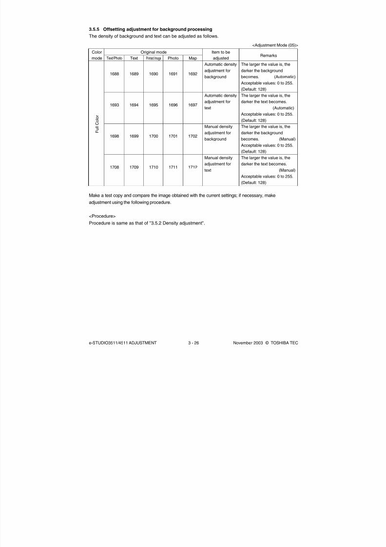
8/2/2019 ES-3511 Service Handbook
http://slidepdf.com/reader/full/es-3511-service-handbook 216/543
e-STUDIO3511/4511 ADJUSTMENT 3 - 26 November 2003 © TOSHIBA TEC
Remarks
The larger the value is, the
darker the background
becomes. (Automatic)
Acceptable values: 0 to 255.
(Default: 128)
The larger the value is, the
darker the text becomes.
(Automatic)
Acceptable values: 0 to 255.
(Default: 128)
The larger the value is, the
darker the background
becomes. (Manual)
Acceptable values: 0 to 255.
(Default: 128)
The larger the value is, the
darker the text becomes.
(Manual)
Acceptable values: 0 to 255.
(Default: 128)
Item to be
adjusted
Automatic density
adjustment for
background
Automatic density
adjustment for
text
Manual density
adjustment for
background
Manual density
adjustment for
text
Printed Image
1690
1695
1700
1710
Photo
1691
1696
1701
1711
Map
1692
1697
1702
1712
Text/Photo
1688
1693
1698
1708
Text
1689
1694
1699
1709
3.5.5 Offsetting adjustment for background processing
The density of background and text can be adjusted as follows.
Make a test copy and compare the image obtained with the current settings; if necessary, make
adjustment using the following procedure.
<Procedure>
Procedure is same as that of "3.5.2 Density adjustment".
F u l l C o l o r
Color
mode
Original mode
<Adjustment Mode (05)>

8/2/2019 ES-3511 Service Handbook
http://slidepdf.com/reader/full/es-3511-service-handbook 217/543
November 2003 © TOSHIBA TEC 3 - 27 e-STUDIO3511/4511 ADJUSTMENT
3.5.6 Judgment threshold for ACS
The judgment level is adjusted for the automatic identification of whether the original set on the glass
is black or color. Namely, this is to adjust the judgment level used when “Auto Color” is selected at a
color mode. The adjustment is available for each of the manually-set original and the original used
with the RADF.
Contents
The larger the value is, the more an original tends to be judged as
black even at the Auto Color Mode. The smaller value is, the more it
tends to be judged as color.
Acceptable values: 0 to 255. (Default: 70)
Code
1675
1676
Item to be adjusted
Judgment threshold
for ACS when original
is set manually
Judgment threshold
for ACS when original
is set on RADF
Make a test copy and compare the image obtained with the current settings; if necessary and make
adjustment.
<Procedure>
Procedure is same as that of "3.5.2 Density adjustment".
3.5.7 Sharpness adjustment
If you want to make copy images look softer or sharper, perform the following adjustment. The adjustment
can be made for each of the color modes and original modes independently.
Make a test copy and compare the image obtained with the current settings; if necessary, make
adjustment.
Note:
You have to make adjustment by balancing between moire and sharpness.
<Procedure>
Procedure is same as that of "3.5.2 Density adjustment".
Code
17371738
1739
1740
1741
604
605
606
1757
Color mode
Full Color
Black
Auto Color
Original mode
Text/PhotoText
Printed Image
Photo
Map
Text/Photo
Text
Photo
Text/Photo
Contents
• The larger the value is, the sharper the image becomes; whilethe smaller the value is, the softer the image becomes.
• The smaller the value is, the less moire tends to appear.
• The acceptable values are 0 to 31.
The center value is 16.
However, 0 is equivalent to the center value.
<Adjustment Mode (05)>
<Adjustment Mode (05)>

8/2/2019 ES-3511 Service Handbook
http://slidepdf.com/reader/full/es-3511-service-handbook 218/543
e-STUDIO3511/4511 ADJUSTMENT 3 - 28 November 2003 © TOSHIBA TEC
3.5.8 Setting range correction
The values of the background peak/text peak in the range correction at the Black Mode can be switched
to "varied" or "fixed" in the following codes.
If they are fixed, the range correction is performed with standard values.
The values of the background peak affects the reproduction of the background density, and the values
of the text peak affects that of the text density.
Make a test copy and compare the image obtained with the current settings; if necessary, make
adjustment.
<Procedure>
Procedure is same as that of "3.5.2 Density adjustment".
Item to be adjusted
Range correction for
original manually set on
the original glass
Range correction for
original set on the RADF
Remarks
The following are the default values set
for each original mode.
Text/Photo: 22, Photo: 12, Text: 22
Each digit stands for:
One's place: Automatic density mode
Ten's place: Manual density mode
The setting conditions possible are as
follows:
Background peak Text peak
1: fixed fixed
2: varied fixed
3: fixed varied
4: varied varied
Text/Photo
570
693
Photo
571
694
Text
572
695
Original mode
<Adjustment Mode (05)>

8/2/2019 ES-3511 Service Handbook
http://slidepdf.com/reader/full/es-3511-service-handbook 219/543
November 2003 © TOSHIBA TEC 3 - 29 e-STUDIO3511/4511 ADJUSTMENT
Make a test copy and compare the image obtained with the current settings; if necessary, make
adjustment.
Note:
Remember the image specifications and life span of the replacing parts may not meet the standard when
the setting value is changed from the default value.
<Procedure>
Procedure is same as that of "3.5.2 Density adjustment".
3.5.9 Setting range correction (Adjustment of background peak)
The levels of the background peak for the range correction at a Black Mode can be set at the following
codes.
Make a test copy and compare the image obtained with the current settings; if necessary, make
adjustment.
<Procedure>
Procedure is same as that of "3.5.2 Density adjustment".
3.5.10 Adjustment of smudged/faint text
The smudge/faint text at a Black Mode can be set at the following codes.
Item to be adjusted
Background peak forrange correction
Remarks
When the value increases, the back-ground (low density area) of the image
is not output.
Acceptable values: 0 to 255.
(Default: Text/Photo: 40, Photo: 16,
Text: 40)
Text/Photo
532
Photo
533
Text
534
Original mode
Item to be adjusted
Adjustment of smudged/
faint text
Remarks
When the value increases, the faint text
is improved. When the value decreases,the smudged text is improved.
Acceptable values: 0 to 255.
(Default: 30)
Text/Photo
648
Original mode
<Adjustment Mode (05)>
<Adjustment Mode (05)>

8/2/2019 ES-3511 Service Handbook
http://slidepdf.com/reader/full/es-3511-service-handbook 220/543
e-STUDIO3511/4511 ADJUSTMENT 3 - 30 November 2003 © TOSHIBA TEC
3.5.11 Adaptation to highlighter
Four modes of one touch adjustment are performed and each mode can be switched into two modes;
highlighter 1 or 2. This adjustment is performed when the reproduction mode for highlighter is needed.
Code
17691770
1771
1772
Remarks
0: Default (Vivid / Clear / Warm / Cool)1: Highlighter 1
2: Highlighter 2
One touch adjustment
VividClear
Warm
Cool
Make a test copy and compare the image obtained with the current settings; if necessary, makeadjustment using the following procedure.
<Procedure>
Procedure is same as that of “3.5.3 Color balance adjustment”.
Notes:
1. When this adjustment is performed, “3.5.1 Automatic gamma adjustment (Black Mode)” (05-580)
needs to be performed since the reproduction of density at Black Mode varies. The result of this
adjustment is not reflected to color/black integrated pattern. Namely, each automatic gamma
adjustment of Black Mode (05-580) or of Color Mode (05-1643) needs to be performed individually
after this adjustment.
2. After this adjustment, set “1” in 08-595 so that the correction result of the Black Mode is not reflected
on “Automatic Calibration”.
3. The setting value must increase as the beam level number (0 to 4) becomes higher. Do not increase
this order when setting the values.
4. Usually, beam level 4 is most effective on all black modes.
Code
667-0
667-1
667-2
667-3
667-4
Remarks
The smaller the value is, the smaller the beam width
becomes. Therefore, the smaller dot is reproduced
accordingly. Acceptable values: 0 to 255.
(Default: Level 0/4: 0, Level 1/4: 63, Level 2/4: 127,
Level 3/4: 191, Level 4/4: 255)
Item to be adjusted
Beam level 0/4
Beam level 1/4
Beam level 2/4
Beam level 3/4
Beam level 4/4
Note:
The color may not always be reproduced precisely due to the characteristics of fluorescent ink.
3.5.12 Beam level conversion setting
The beam level for 4 divided smoothing is set at the Black Mode. This adjustment enables to adjust
the dot size.
<Adjustment Mode (05)>
<Adjustment Mode (05)>

8/2/2019 ES-3511 Service Handbook
http://slidepdf.com/reader/full/es-3511-service-handbook 221/543
November 2003 © TOSHIBA TEC 3 - 31 e-STUDIO3511/4511 ADJUSTMENT
Code
1612
16131614
1615
1616
Remarks
The smaller the value is, the toner amount adhered
decreases of the high density area (ex. prevention offusing offsetting, etc).
Acceptable values : 0 to 255.
(Default: Plain paper: 255, Thick paper 1: 249,
Thick paper 2: 237, Thick paper 3: 237,
OHP film: 249)
Paper type
Plain paper
Thick paper 1Thick paper 2
Thick paper 3
OHP film
Note:
The larger the value is, the more frequently fusing offsetting occurs.
3.5.14 Maximum text density adjustment
The maximum text density of each color at Full Color Mode can be adjusted as follows.
3.5.13 Maximum toner density adjustment to paper type
The maximum toner amount adhering to the paper can be controlled.
Make a test copy and compare the image obtained with the current settings; if necessary, make
adjustment using the following procedure.
Note:
Be sure that this adjustment be made after performing “3.5.1 Automatic gamma adjustment”.
<Procedure>
Procedure is same as that of “3.5.2 Density adjustment”.
Code
1630
1631
1632
1633
Remarks
The larger the value is, the darker the maximum text
density of each color to be adjusted becomes.
Acceptable values: 0 to 10 (Default: 5)
Item to be adjusted
Maximum text density
Color
Yellow
Magenta
Cyan
Black
<Adjustment Mode (05)>
<Adjustment Mode (05)>
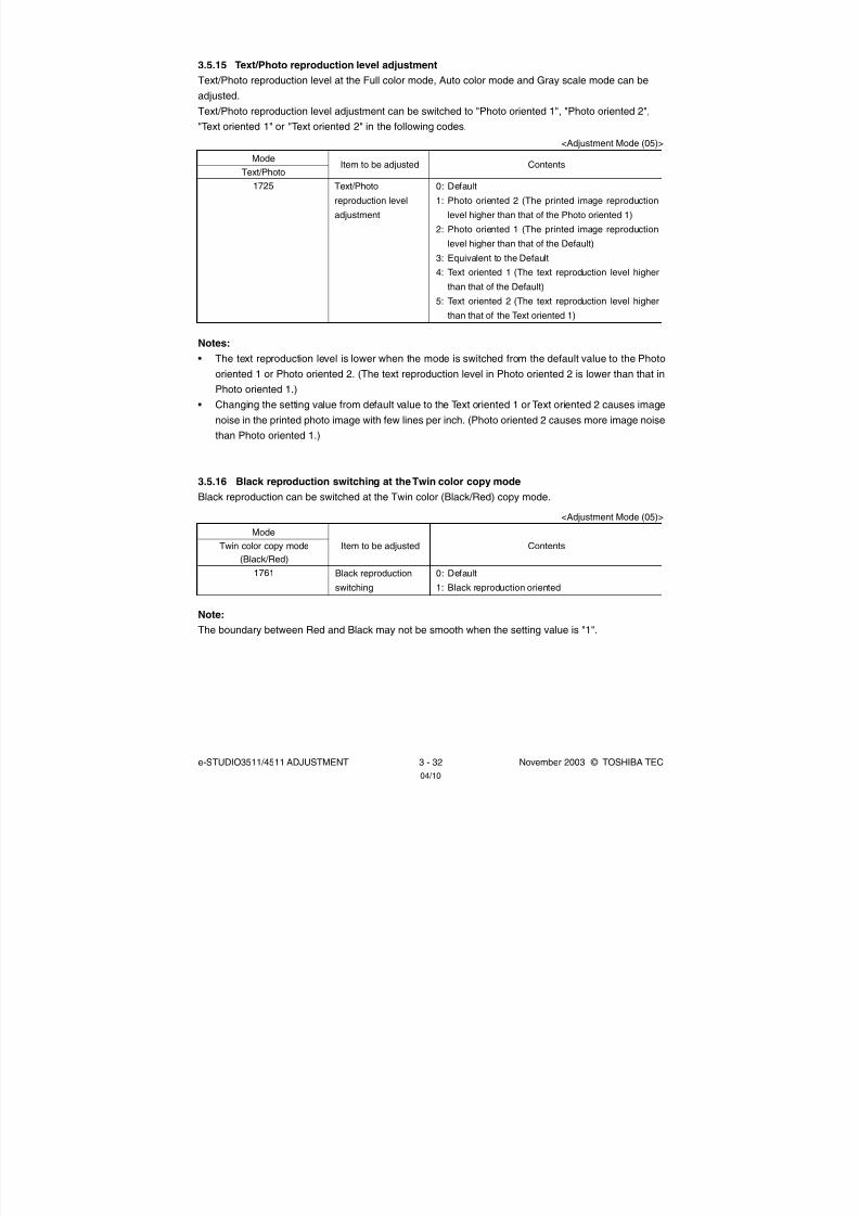
8/2/2019 ES-3511 Service Handbook
http://slidepdf.com/reader/full/es-3511-service-handbook 222/543
e-STUDIO3511/4511 ADJUSTMENT 3 - 32 November 2003 © TOSHIBA TEC04/10
Notes:
• The text reproduction level is lower when the mode is switched from the default value to the Photo
oriented 1 or Photo oriented 2. (The text reproduction level in Photo oriented 2 is lower than that in
Photo oriented 1.)
• Changing the setting value from default value to the Text oriented 1 or Text oriented 2 causes image
noise in the printed photo image with few lines per inch. (Photo oriented 2 causes more image noise
than Photo oriented 1.)
3.5.16 Black reproduction switching at the Twin color copy mode
Black reproduction can be switched at the Twin color (Black/Red) copy mode.
3.5.15 Text/Photo reproduction level adjustment
Text/Photo reproduction level at the Full color mode, Auto color mode and Gray scale mode can be
adjusted.
Text/Photo reproduction level adjustment can be switched to "Photo oriented 1", "Photo oriented 2",
"Text oriented 1" or "Text oriented 2" in the following codes.
Item to be adjusted
Text/Photo
reproduction level
adjustment
Contents
0: Default
1: Photo oriented 2 (The printed image reproduction
level higher than that of the Photo oriented 1)
2: Photo oriented 1 (The printed image reproduction
level higher than that of the Default)
3: Equivalent to the Default
4: Text oriented 1 (The text reproduction level higher
than that of the Default)
5: Text oriented 2 (The text reproduction level higherthan that of the Text oriented 1)
Text/Photo
1725
Mode
<Adjustment Mode (05)>
Item to be adjusted
Black reproduction
switching
Contents
0: Default
1: Black reproduction oriented
Twin color copy mode
(Black/Red)
1761
Mode
<Adjustment Mode (05)>
Note:
The boundary between Red and Black may not be smooth when the setting value is "1".

8/2/2019 ES-3511 Service Handbook
http://slidepdf.com/reader/full/es-3511-service-handbook 223/543
November 2003 © TOSHIBA TEC 3 - 33 e-STUDIO3511/4511 ADJUSTMENT
3.6 Image Quality Adjustment (Printing Function)
3.6.1 Automatic gamma adjustment
When the reproduction of gradation is not appropriate, the gradation reproducibility of all colors Y, M,
C and K can be corrected by performing this automatic gamma adjustment. In case the gradation
reproduction of the image checked is not satisfactory, make this adjustment as described below at
parts replacement.
Contents
<Procedure>
(1) While pressing [0] and [5] simultaneously, turn the power ON.→
Adjustment Mode
(2) Select the A4/LT drawer. Key in the pattern number and press
the [FAX] button to output a “Patch chart for gamma adjustment”.
Pattern No. Language/Resolution Remarks
47 PS/600x600dpi When performing code 100048* PS/1200x600dpi When performing code 1001
49 PCL/600x600dpi When performing code 1002
50* PCL/1200x600dpi When performing code 1003
*Perform the adjustment only when the expansion memory has
been installed.
(3) Place the patch chart for adjustment printed in step (2) face down
on the original glass, with its side, on which two black squares are
present, aligned against the original scale.
(4) Key in a code and press the [START] button.
→ The scanner reads the chart automatically and performs
automatic gamma adjustment calculation (approx. 30 sec.).(5) When the adjustment has finished normally, “ENTER” is shown.
Press the [ENTER] button to have the adjustment results reflected.
(To cancel the reflection of adjustment results, press the [CANCEL]
button.)
In the case of an abnormal ending, “ADJUSTMENT ERROR” is
shown. Press the [CANCEL] button to clear the error display.
When it is cleared, the control panel display will return to the
ready state. Then, check if the patch chart on the original glass
is placed in the wrong direction or if it is placed inclined on the
original glass, and then repeat step (3) and afterward.
Code
1000
1001
1002
1003
Adjustment item
Automatic gamma
adjustment
<Adjustment Mode (05)>
(2) When any of the following parts are replaced or adjusted, make a print and check the image to
determine if adjustment is necessary:
•2nd transfer roller
Note: Be sure that this adjustment be made after performing the image adjustment in "3.3Adjustment of Image Quality Control" and "3.4 Image Dimensional Adjustment".
(1) When unpacking or any of the following parts has been unpacked or replaced, be sure to make
this adjustment:
• Laser optical unit • Photoconductive drum • Developer material
•Main charger wire • Main charger grid • Transfer belt
• 1st transfer roller • Drum cleaning blade • Drum cleaner brush
• Image guality sensor
04/05

8/2/2019 ES-3511 Service Handbook
http://slidepdf.com/reader/full/es-3511-service-handbook 224/543
e-STUDIO3511/4511 ADJUSTMENT 3 - 34 November 2003 © TOSHIBA TEC
3.6.2 Gamma balance adjustment (Black Mode)
The gamma balance is adjusted by adjusting the density at the Black Mode. The adjustment is performed
by selecting its density area from the following: low density, medium density and high density.
<Procedure>
(1) While pressing [0] and [5] simultaneously, turn the power ON.
(2) Key in the codes to be adjusted (language and screen) and press the [START] button.
(3) Key in the value corresponding to the density area to be adjusted (0, 1 or 2) and press the
[START] button.
0: Low density (L) 1: Medium density (M) 2: High density (H)
(4) Key in the adjustment value. (To correct the value once keyed in, press [CLEAR] button.)
(5) Press the [ENTER] or [INTERRUPT] button to store the value in memory.→ The equipment goes
back to the ready state.
(6) For resetting the value, repeat step (2) to (5).
(7) Let the equipment restart and perform printing job.
(8) If the image density has not been attained, repeat step (1) to (7).
Item to be
adjusted
Low density
Medium density
High density
Detail(PCL)
599-0
599-1
599-2
Remarks
The larger the value is, the
density of the item to be
adjusted becomes darker.
Acceptable values: 0 to 255.
(Default: 128)
Smooth(PS)
596-0
596-1
596-2
Detail(PS)
597-0
597-1
597-2
Smooth(PCL)
598-0
598-1
598-2
Language and screenColor
mode
Black
<Adjustment Mode (05)>

8/2/2019 ES-3511 Service Handbook
http://slidepdf.com/reader/full/es-3511-service-handbook 225/543
November 2003 © TOSHIBA TEC 3 - 35 e-STUDIO3511/4511 ADJUSTMENT
Density
Low
Medium
High
Low
Medium
High
Low
Medium
High
Low
Medium
High
Remarks
The larger the
value is, the
darker the color
to be adjusted
becomes.
Acceptable
values: 0 to 255.
(Default: 128)
Smooth
1010-0
1010-1
1010-2
1011-0
1011-1
1011-2
1012-0
1012-1
1012-2
1013-0
1013-1
1013-2
Detail
1014-0
1014-1
1014-2
1015-0
1015-1
1015-2
1016-0
1016-1
1016-2
1017-0
1017-1
1017-2
Smooth
1018-0
1018-1
1018-2
1019-0
1019-1
1019-2
1020-0
1020-1
1020-2
1021-0
1021-1
1021-2
Detail
1022-0
1022-1
1022-2
1023-0
1023-1
1023-2
1024-0
1024-1
1024-2
1025-0
1025-1
1025-2
Smooth
1026-0
1026-1
1026-2
1027-0
1027-1
1027-2
1028-0
1028-1
1028-2
1029-0
1029-1
1029-2
Detail
1030-0
1030-1
1030-2
1031-0
1031-1
1031-2
1032-0
1032-1
1032-2
1033-0
1033-1
1033-2
Smooth
1034-0
1034-1
1034-2
1035-0
1035-1
1035-2
1036-0
1036-1
1036-2
1037-0
1037-1
1037-2
Detail
1038-0
1038-1
1038-2
1039-0
1039-1
1039-2
1040-0
1040-1
1040-2
1041-0
1041-1
1041-2
3.6.3 Color balance adjustment (Color Mode)
The color balance is adjusted by adjusting the density of each color. The adjustment is performed by
selecting its density area from the following: low density, medium density and high density.
Note:
Be sure that this adjustment be made after performing “3.6.1 Automatic gamma adjustment”.
<Procedure>
Procedure is same as that of "3.6.2 Gamma balance adjustment".
Color
Yellow
Magenta
Cyan
Black
PS
600x600dpi 1200x600dpi
PCL
600x600dpi 1200x600dpi
<Adjustment Mode (05)>

8/2/2019 ES-3511 Service Handbook
http://slidepdf.com/reader/full/es-3511-service-handbook 226/543
e-STUDIO3511/4511 ADJUSTMENT 3 - 36 November 2003 © TOSHIBA TEC
3.6.4 Adjustment of smudged/faint text
The smudged/faint text at the Black Mode is adjusted.
<Procedure>
(1) While pressing [0] and [5] simultaneously, turn the power ON.
(2) Key in the codes to be adjusted and press the [START] button.
(3) Key in the adjustment value. (To correct the value once keyed in, press [CLEAR] button.)
(4) Press the [ENTER] or [INTERRUPT] button to store the value in memory.→ The equipment goes
back to the ready state.
(5) For resetting the value, repeat step (2) to (4).
(6) Let the equipment restart and perform printing job.
(7) If the desired image has not been attained, repeat step (1) to (6).
3.6.5 Upper limit value at Toner Saving Mode
The upper limit value is adjusted at the Toner Saving Mode.
PS
654
Remarks
When the value increases, the smudged text is improved.
When the value decreases, the faint text is improved.
Acceptable values: 0 to 9 (Default: 5)
Language
PCL
655
<Procedure>
Procedure is same as that of “3.6.4 Adjustment of smudged/faint text”.
PS
664
PCL
665
PS
1200x600dpi1056
PS
600x600dpi1055
Remarks
The smaller the value is, the lighter
the density of image becomes.
Acceptable values: 0 to 255.
(Default: 176)
PCL
600x600dpi1057
PCL
1200x600dpi1058
Black mode Color mode
<Adjustment Mode (05)>
<Adjustment Mode (05)>

8/2/2019 ES-3511 Service Handbook
http://slidepdf.com/reader/full/es-3511-service-handbook 227/543
November 2003 © TOSHIBA TEC 3 - 37 e-STUDIO3511/4511 ADJUSTMENT
Code
663
Remarks
The smaller the value is, the dot size becomes smaller.
Acceptable values: 0 to 255. (Default: 255)
<Adjustment Mode (05)>
3.6.6 Dot size adjustment in black printing
The dot size is adjusted in primary scanning direction in black printing.
<Procedure>
Procedure is same as that of “3.6.2 Gamma balance adjustment”.
Note:
The larger the value is, the more frequently fusing offsetting occurs.
3.6.8 Image processing: Gamma correction table all clearing
The state of calibration in color printing mode is initialized at the Setting Mode (08-597). This setting is to
be performed when a defect occurs in “Automatic gamma adjustment (05-1000 to 1003)”. The cause of
defect is presumed as an image failure (jittering or uneven image density) at the patch chart for gamma
adjustment.
<Procedure>
Procedure is same as that of “3.6.4 Adjustment of smudged/faint text”.
3.6.7 Maximum toner density adjustment to paper type
The maximum toner amount adhering to the paper can be controlled.
PS1046-0
1047-0
1048-0
1049-0
1050-0
Remarks
The smaller the value is, the toner amount adhered decreases of the
high density area (ex. prevention of fusing offsetting, etc).
Acceptable values: 0 to 255. (Default: Plain paper: 255, Thick paper 1:
255, Thick paper 2: 255, Thick paper 3: 255, OHP film: 200)
PCL1046-1
1047-1
1048-1
1049-1
1050-1
<Adjustment Mode (05)>
Paper type
Plain paper
Thick paper 1
Thick paper 2
Thick paper 3
OHP film
Code

8/2/2019 ES-3511 Service Handbook
http://slidepdf.com/reader/full/es-3511-service-handbook 228/543
e-STUDIO3511/4511 ADJUSTMENT 3 - 38 November 2003 © TOSHIBA TEC
3.7 Image Quality Adjustment (Scanning Function)
3.7.1 Gamma balance adjustment
The gamma balance at the Black Mode is adjusted by adjusting the density. The adjustment is performed
by selecting its density area from the following: low density, medium density and high density.
Remarks
The larger the value is, the densityof the item to be adjusted becomesdarker.Acceptable values: 0 to 255.(Default: 128)
<Procedure>
(1) While pressing [0] and [5] simultaneously, turn the power ON.
(2) Key in the code corresponding to the desired original mode and press the [START] button.
(3) Key in the value corresponding to the density area to be adjusted (0, 1 or 2) and press the
[START] button.
0: Low density (L) 1: Medium density (M) 2: High density (H)
(4) Key in the adjustment value. (To correct the value once keyed in, press [CLEAR] button.)
(5) Press the [ENTER] or [INTERRUPT] button to store the value in memory.→ The equipment goes
back to the ready state.
(6) For resetting the value, repeat step (2) to (5).
(7) Let the equipment restart and perform scanning job.
(8) If the desired image has not been attained, repeat step (1) to (7).
Item to be
adjusted
Low density
Medium density
High density
Black
Text/Photo
880-0
880-1
880-2
Black
Text
881-0
881-1
881-2
Black
Photo
882-0
882-1
882-2
Gray Scale
mode
883-0
883-1
883-2
Original mode<Adjustment Mode (05)>
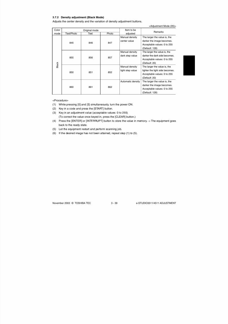
8/2/2019 ES-3511 Service Handbook
http://slidepdf.com/reader/full/es-3511-service-handbook 229/543
November 2003 © TOSHIBA TEC 3 - 39 e-STUDIO3511/4511 ADJUSTMENT
Remarks
The larger the value is, the
darker the image becomes.
Acceptable values: 0 to 255
(Default: 128)
The larger the value is, the
darker the dark side becomes.
Acceptable values: 0 to 255
(Default: 20)
The larger the value is, the
lighter the light side becomes.
Acceptable values: 0 to 255
(Default: 20)
The larger the value is, the
darker the image becomes.
Acceptable values: 0 to 255
(Default: 128)
Item to be
adjusted
Manual density
center value
Manual density
dark step value
Manual density
light step value
Automatic density
Text
846
856
851
861
Photo
847
857
852
862
Text/Photo
845
855
850
860
3.7.2 Density adjustment (Black Mode)
Adjusts the center density and the variation of density adjustment buttons.
<Procedure>
(1) While pressing [0] and [5] simultaneously, turn the power ON.
(2) Key in a code and press the [START] button.
(3) Key in an adjustment value (acceptable values: 0 to 255).
(To correct the value once keyed in, press the [CLEAR] button.)
(4) Press the [ENTER] or [INTERRUPT] button to store the value in memory.→ The equipment goesback to the ready state.
(5) Let the equipment restart and perform scanning job.
(6) If the desired image has not been attained, repeat step (1) to (5).
B l a c k
Color
mode
Original mode
<Adjustment Mode (05)>

8/2/2019 ES-3511 Service Handbook
http://slidepdf.com/reader/full/es-3511-service-handbook 230/543
e-STUDIO3511/4511 ADJUSTMENT 3 - 40 November 2003 © TOSHIBA TEC
Code
848
858
853
<Procedure>
(1) While pressing [0] and [5] simultaneously, turn the power ON.
(2) Key in the codes and press the [START] button.
(3) Key in the adjustment values. Acceptable values : 0 to 255. (To correct the value once keyed in,
press [CLEAR] button.)
(4) Press the [ENTER] or [INTERRUPT] button to store the value in memory.→ The equipment goes
back to the ready state.
(5) Let the equipment restart and perform scanning job.
(6) If the desired image has not been attained, repeat step (1) to (5).
3.7.4 Background adjustment (Color Mode)
The adjustment level of background center value is adjusted. The control value of background
adjustment button is automatically adjusted to the same level as the adjusted center value.
For example, when the control value of background adjustment key ranges from 0 to 6, the
background center value (-2 to +2) is used to be the range from 6 to 14 accordingly.
3.7.3 Background adjustment (Gray Scale Mode)
The adjustment level of background center value and the control of background adjustment button are
adjusted.
Item to be adjusted
Center value
Dark step value
Light step value
Remarks
The larger the value is, the background becomes darker. The smaller the
value is, the background becomes lighter.
Acceptable values: 0 to 255 (Default: 128)
The larger the value is, the image of the “dark” steps becomes darker.
Acceptable values: 0 to 255 (Default: 20)
The larger the value is, the image of the “light” steps becomes lighter.
Acceptable values: 0 to 255 (Default: 35)
Code
1070
1071
1072
Original mode
Text
Printed Image
Photo
Remarks
The larger the value is, the background becomes lighter.
Acceptable values: 0 to 50 (Default: 0)
<Procedure>(1) While pressing [0] and [5] simultaneously, turn the power ON.
(2) Key in the codes and press the [START] button.
(3) Key in the adjustment values. Acceptable values : 0 to 50. (To correct the value once keyed in,
press [CLEAR] button.)
(4) Press the [ENTER] or [INTERRUPT] button to store the value in memory.→ The equipment goes
back to the ready state.
(5) Let the equipment restart and perform scanning job.
(6) If the desired image has not been attained, repeat step (1) to (5).
Before adjustment
After adjustment
0 1 2 3 4 5 6 7 8 9 10 11 12 13 14 15 16 17
+2 +1 0 -1 -2
+2 +1 0 -1 -2
<Adjustment Mode (05)>
<Adjustment Mode (05)>

8/2/2019 ES-3511 Service Handbook
http://slidepdf.com/reader/full/es-3511-service-handbook 231/543
November 2003 © TOSHIBA TEC 3 - 41 e-STUDIO3511/4511 ADJUSTMENT
Note:
You have to make adjustment by balancing between moire and sharpness.
<Procedure>
Procedure is same as that of "3.7.2 Density adjustment (Black Mode)".
<Procedure>
Procedure is same as that of "3.7.2 Density adjustment (Black Mode)".
3.7.6 Sharpness adjustment
If you want to make scan images look softer or sharper, perform the following adjustment. The adjustment
can be made for each of the color modes and original modes independently.
3.7.5 Judgment threshold for ACS
The judgment level is adjusted for the automatic identification of whether the original set on the glass
is black or color. Namely, this is to adjust the judgment level used when “Auto Color” is selected at
color modes. The adjustment is available for both the manually-set original and the original used with
the RADF.
Code
1065
1066
Contents
The larger the value is, the more an original tends to be judged as black
even at the Auto Color Mode. The smaller the value is, the more it tends
to be judged as color.
Acceptable values: 0 to 255 (Default: 70)
Item to be adjusted
Judgment threshold for
ACS when original is set
manually
Judgment threshold for
ACS when original is set
on RADF
Contents
• The larger the value is, the sharper the image becomes; while
the smaller the value is, the softer the image becomes.
• The smaller the value is, the less moire tends to appear.
• The acceptable values are 0 to 31.The center value is 16.
However, 0 is equivalent to the center value.
Original mode
Text
Printed Image
Photo
Text/PhotoText
Photo
-
Code
1086
1087
1088
840841
842
843
Color mode
Full Color
Black
Gray Scale
<Adjustment Mode (05)><Adjustment Mode (05)>
<Adjustment Mode (05)>

8/2/2019 ES-3511 Service Handbook
http://slidepdf.com/reader/full/es-3511-service-handbook 232/543
e-STUDIO3511/4511 ADJUSTMENT 3 - 42 November 2003 © TOSHIBA TEC
<Procedure>
Procedure is same as that of "3.7.2 Density adjustment (Black Mode)".
3.7.8 Setting range correction (Adjustment of background peak)
The levels of the background peak for the range correction at the Black Mode can be set at the following
codes.
<Procedure>
Procedure is same as that of "3.7.2 Density adjustment (Black Mode)".
3.7.7 Setting range correction
The values of the background peak / text peak in the range correction at the Black Mode can be switched
to "varied" or "fixed" in the following codes.
If they are fixed, the range correction is performed with standard values.
The values of the background peak affects the reproduction of the background density and the values
of the text peak affects that of the text density.
Text/Photo
825
830
Remarks
The following are the default values set
for each original mode.
Photo/Text: 12, Text: 12, Photo: 12,
Gray Scale: 12
Each digit stands for:
Ones place: Automatic density mode
Tens place: Manual density mode
The setting conditions possible are asfollows:
Background peak Text peak
1: fixed fixed
2: varied fixed
3: fixed varied
4: varied varied
Text
826
831
Photo
827
832
Gray Scale
828
833
Item to be adjusted
Range correction for
original manually set
on the original glass
Range correction for
original set on theRADF
Black
Original mode
Text/Photo
835
Remarks
When the value increases, the back-
ground (low density section) of the image
is not output.Acceptable vales: 0 to 255
(Default: Text/Photo: 56, Text: 64,
Photo: 48, Gray Scale: 48)
Text
836
Photo
837
Gray Scale
838
Item to be adjusted
Background peak for
range correction
Black
Original mode
<Adjustment Mode (05)>
<Adjustment Mode (05)>

8/2/2019 ES-3511 Service Handbook
http://slidepdf.com/reader/full/es-3511-service-handbook 233/543
November 2003 © TOSHIBA TEC 3 - 43 e-STUDIO3511/4511 ADJUSTMENT
3.7.9 Fine adjustment of black density
The density of black side on scanned image is adjusted at color-scanning.
Note:
Be careful for the value not to be too large since the gradation is reproduced worse in darker side.
<Procedure>
(1) While pressing [0] and [5] simultaneously, turn the power ON.
(2) Key in the codes and press the [START] button.
(3) Key in the adjustment values. Acceptable values : 0 to 4. (To correct the value once keyed in,
press [CLEAR] button.)
(4) Press the [ENTER] or [INTERRUPT] button to store the value in memory. → The equipment
goes back to the ready state.
(5) Let the equipment restart and perform scanning job.
(6) If the desired image has not been attained, repeat step (1) to (5).
3.7.10 RGB conversion method selection
The color space conversion method of image is decided at color-scanning.
Code
1075
1076
1077
Original mode
Text
Printed Image
Photo
Remarks
The larger the value is, the black side of the image becomes darker.
Acceptable values: 0 to 4 (Default: 0)
<Procedure>
(1) While pressing [0] and [5] simultaneously, turn the power ON.
(2) Key in the codes and press the [START] button.
(3) Key in the adjustment values. Acceptable values : 0 to 3. (To correct the value once keyed in,
press [CLEAR] button.)
(4) Press the [ENTER] or [INTERRUPT] button to store the value in memory. → The equipment goes
back to the ready state.
(5) Let the equipment restart and perform scanning job.
(6) If the desired image has not been attained, repeat step (1) to (5).
Code
1080
1081
1082
Original mode
Text
Printed Image
Photo
Remarks
0: sRGB 1: AppleRGB 2: ROMMRGB 3: AdobeRGB
(Default: 0)
<Adjustment Mode (05)>
<Adjustment Mode (05)>

8/2/2019 ES-3511 Service Handbook
http://slidepdf.com/reader/full/es-3511-service-handbook 234/543
e-STUDIO3511/4511 ADJUSTMENT 3 - 44 November 2003 © TOSHIBA TEC
Remarks
When the value increases, the image is zoomed in.When the value decreases, the image is zoomed out.
Acceptable values: 0 to 255 (Default: 128)
* 0.1%/step
Code
884
<Adjustment Mode (05)>
3.7.11 Reproduction ratio of primary scanning direction (black)
The reproduction ratio of primary scanning direction with the resolution other than 600 dpi is adjusted
in Scanning Function for black image.
<Procedure>
Procedure is same as that of “3.7.2 Density adjustment”.
<Procedure>
Procedure is same as that of “3.7.2 Density adjustment”.
3.7.12 Reproduction ratio of primary scanning direction (color)
The reproduction ratio of primary scanning direction with the resolution other than 600 dpi is adjusted
in Scanning Function for color image.
Remarks
When the value increases, the image is zoomed in.
When the value decreases, the image is zoomed out.
Acceptable values: 0 to 255 (Default: 128)
* 0.1%/step
Code
1060
<Adjustment Mode (05)>

8/2/2019 ES-3511 Service Handbook
http://slidepdf.com/reader/full/es-3511-service-handbook 235/543
November 2003 © TOSHIBA TEC 3 - 45 e-STUDIO3511/4511 ADJUSTMENT
3.8 High-Voltage Transformer Setting
3.8.1 General description
The high-voltage transformers (PS-HVT-350) supply high-voltage to the parts related to charging,
development, transfer and drum cleaning.
The high-voltage transformer has the following high-voltage outputs.
CH1: Main charger wire
CH2: Main charger grid bias
CH3: Color developer bias
CH4: Black developer bias
CH5: 1st transfer roller bias
CH6: 2nd transfer roller bias
CH7: Cleaning blade bias
Note:
Make sure not to lose the data sheets which are attached to the high-voltage transformers. Use these
sheets for the following setting.
Never move the fixed volumes of resistors since output adjustment is performed when the devices are
shipped.
3.8.2 Setting at the replacement of high-voltage transformer
After replacing a high-voltage transformer, be sure to enter the data shown on the data sheets (main
charger grid bias, color/black developer bias and 1st/2nd transfer roller bias) noted above according to
the following procedure.
(1) While pressing [0] and [5] simultaneously, turn the power ON.
(2) Key in the adjusting codes in the table below and press the [START] button.
(3) Key in the adjusting value corresponding to each code on the attached sheets, and then press
[ENTER] or [INTERRUPT].
(4) Key in all the codes in the above table by repeating (2) and (3).
(5) Turn the power OFF.
Adjusting code
334
335
338
339
372
373
250
251
252
253
Item to be adjusted
Main charger grid bias lower limit value
Main charger grid bias upper limit value
Color developer bias lower limit value
Color developer bias upper limit value
Black developer bias lower limit value
Black developer bias upper limit value
1st transfer roller bias lower limit value
1st transfer roller bias upper limit value
2nd transfer roller bias lower limit value (+)
2nd transfer roller bias upper limit value (+)
Adjusting value
Refer to the data sheets
<Adjustment Mode (05)>

8/2/2019 ES-3511 Service Handbook
http://slidepdf.com/reader/full/es-3511-service-handbook 236/543
e-STUDIO3511/4511 ADJUSTMENT 3 - 46 November 2003 © TOSHIBA TEC
3.9 Adjustment of the Scanner Section
3.9.1 Carriages
(1) Installing carriage wires
When replacing the carriage wires, refer illustrations below:
Fig. 3-901
Adjustment of the carriage wire tension is not necessary since a certain tension is applied to the
carriage wires by the tension springs.
Note:
Make sure the tension applied to the wire is normal.
Wire pulley
Tension spring
Bracket for carriage-1
Carriage wireCarriage-2
Idler pulley
Hook
Idler pulley
Carriage-2
Carriage wire
Bracket for carriage-1
Hook
Tension spring
Wire pulley
[Front side]
[Rear side]

8/2/2019 ES-3511 Service Handbook
http://slidepdf.com/reader/full/es-3511-service-handbook 237/543
November 2003 © TOSHIBA TEC 3 - 47 e-STUDIO3511/4511 ADJUSTMENT
(2) Adjusting carriages-1 and -2 positions
a. Move the carriage-2 toward the exit side.
b. Loosen the screws fixing the front side pulley bracket, make the sections A and B of the
carriage-2 touch with the inside of the exit side frame and screw them up.
Fig. 3-902
c. Put the carriage-1 on the rail, make the sections C and D of it touch with the inside of the exit
frame and screw up the front/rear side of the bracket to fix it.
Note:
Make sure that the sections A and B of the carriage-2 touch with the exit side frame.
Carriage-2 Pulley bracket
Exit side frame
B A
Carriage-1
Exit side frame
D C
Bracket Bracket
[Rear] [Front]
[Rear] [Front]
Enlarged view of carriage
Enlarged view of carriage
Fig. 3-903

8/2/2019 ES-3511 Service Handbook
http://slidepdf.com/reader/full/es-3511-service-handbook 238/543
e-STUDIO3511/4511 ADJUSTMENT 3 - 48 November 2003 © TOSHIBA TEC
(3) Assembling carriage wires
Winding the wire around the wire pulley:
a. Pull the Ø3 ball terminal located at the center of the wire into a hole on the wire pulley. One
end of the wire with a hook attached comes to the outside.
b. Wind the wires around the wire pulleys of the front and rear sides. The number of turns to be
wound are as follows:
• 2 turns toward the opposite side of the boss
• 4 turns toward the boss side
Notes:
Pay attention to the followings when the wires are wound around the pulleys:
• Do not twist the wire.
• Wind the wires tightly so that they are in complete contact with the surface of the pulleys.
• Each turn should be pushed against the previously wound turn so that there is no space
between them.
No space between turns
4 turns
2 turns
Ball terminal
Hook
Color: Silver
4 turns
2 turns
Ball terminal
Hook
Color: Black
[Rear] [Front]
Fig. 3-904
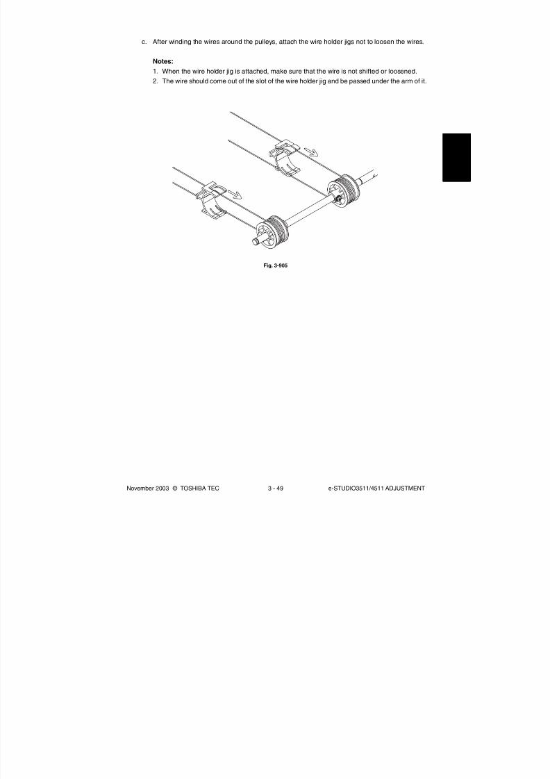
8/2/2019 ES-3511 Service Handbook
http://slidepdf.com/reader/full/es-3511-service-handbook 239/543
November 2003 © TOSHIBA TEC 3 - 49 e-STUDIO3511/4511 ADJUSTMENT
c. After winding the wires around the pulleys, attach the wire holder jigs not to loosen the wires.
Notes:
1. When the wire holder jig is attached, make sure that the wire is not shifted or loosened.
2. The wire should come out of the slot of the wire holder jig and be passed under the arm of it.
Fig. 3-905

8/2/2019 ES-3511 Service Handbook
http://slidepdf.com/reader/full/es-3511-service-handbook 240/543
e-STUDIO3511/4511 ADJUSTMENT 3 - 50 November 2003 © TOSHIBA TEC
3.9.2 Lens unit
(1) Replacing the lens unit
• The lens unit must not be readjusted and some part of its components must not be replaced in
the field since the unit is precisely adjusted. If any of the components is defective, replace the
whole unit.
• When replacing the unit, do not loosen or remove the 4 screws indicated with the arrows.
Fig. 3-906
• Handle the unit with care. Do not hold the lens and adjusted part (hold the unit as shown below).
Fig. 3-907

8/2/2019 ES-3511 Service Handbook
http://slidepdf.com/reader/full/es-3511-service-handbook 241/543
November 2003 © TOSHIBA TEC 3 - 51 e-STUDIO3511/4511 ADJUSTMENT
(2) Installation of lens unit
Follow the procedure below when installing and replacing the lens unit.
<Procedure>
1. Attach the lens unit and fix it temporarily with 2 screws.
2. Match the center scale of the plate in which the unit is to be installed and the rightmost scale
of the adjusting hole on the lens unit plate.
[Front]
Fig. 3-908
3. Tighten 5 screws securely to fix the lens unit while pushing it to the rear side and fix 2 groundwires with the screws.
Screw
[Rear]
[Rear]
[Front]
Fig. 3-909
Screw
Screw
Screw
Ground wire
Screw
Ground wire

8/2/2019 ES-3511 Service Handbook
http://slidepdf.com/reader/full/es-3511-service-handbook 242/543
e-STUDIO3511/4511 ADJUSTMENT 3 - 52 November 2003 © TOSHIBA TEC
3.10 Adjustment of the Paper Feeding System
3.10.1 Sheet sideways deviation caused by paper feeding
<Procedure>
• The center of the printed image shifts to the
front side.→ Move the guide to the front side
(Arrow (A) direction in the lower figure).
• The center of the printed image shifts to the
rear side.→ Move the guide to the rear side
(Arrow (B) direction in the lower figure).
• Bypass feeding • Drawer feeding
Feeding
directionCenter
[Front] [Front]
Feeding
direction
Center
(A) (B)
(A)
(B)
Fig. 3-1001 Fig. 3-1002
Fig. 3-1003 Fig. 3-1004

8/2/2019 ES-3511 Service Handbook
http://slidepdf.com/reader/full/es-3511-service-handbook 243/543
November 2003 © TOSHIBA TEC 3 - 53 e-STUDIO3511/4511 ADJUSTMENT
3.11 Adjustment of the Developer Unit
3.11.1 Doctor-to-sleeve gap (black developer unit)
Adjustment tool to use: Doctor-sleeve jig
Adjusting procedure:
(1) Take off the black developer unit from the
equipment.
(2) Remove 2 screws and take off the developer
material cover. Then discharge the developer
material.
(3) Remove 2 screws and take off the doctor
blade cover.
(4) Loosen 2 doctor blade fixing screws. Insert
the gauge “0.55” of the doctor sleeve jig
between the developer sleeve and doctor
blade to adjust the gap, and tighten the
screws.
Developer
material cover
Screw
Screw
Screw
Doctor blade
cover
Doctor-sleeve
jig
Developer sleeve
Doctor blade
Screw
Fig. 3-1101
Fig. 3-1102
Fig. 3-1103

8/2/2019 ES-3511 Service Handbook
http://slidepdf.com/reader/full/es-3511-service-handbook 244/543
e-STUDIO3511/4511 ADJUSTMENT 3 - 54 November 2003 © TOSHIBA TEC
Notes:
1. When confirming and adjusting the gap between the developer sleeve and the doctor blade, insert
the gauges into the gap after rotating the developer sleeve so that its marking faces the doctor
blade.
2. While reattaching the black developer unit cover, set the latches securely.
3.11.2 Doctor-to-sleeve gap (color developer unit)
Adjustment tool to use : Doctor-sleeve jig
(5) Insert the gauge “0.50” of the doctor-sleeve
jig into the gap between the developer
sleeve and doctor blade and make sure that
the gauge can move smoothly in the front/
rear direction. In addition, confirm that the
gauge “0.60” cannot be inserted into the
gap.
Developer sleeve
Doctor-sleeve
jig
Doctor blade
Adjusting procedure:
(1) Take off the color developer unit from the
equipment.
(2) Remove 2 screws and take off the
developer material cover. Then discharge
the developer material.
ScrewScrew
Developer material cover
(3) Remove 4 screws and the toner-scattering
prevention seal holder.
Screw Toner-scattering prevention
seal holder
Fig. 3-1104
Fig. 3-1105
Fig. 3-1106

8/2/2019 ES-3511 Service Handbook
http://slidepdf.com/reader/full/es-3511-service-handbook 245/543
November 2003 © TOSHIBA TEC 3 - 55 e-STUDIO3511/4511 ADJUSTMENT
Notes:
1. When confirming and adjusting the gap between the developer sleeve and the doctor blade, insert
the gauges into the gap after rotating the developer sleeve so that its marking faces the doctor
blade.2. While reattaching the color developer unit cover, set the latches securely.
(5) Insert the gauge “0.50” of the doctor-sleeve
jig into the gap between the developer
sleeve and doctor blade and make sure that
the gauge can move smoothly in the front/
rear direction. In addition, confirm that the
gauge “0.60” cannot be inserted into the
gap.
(4) Loosen 2 doctor blade fixing screws. Insert
the gauge “0.55” of the doctor-sleeve jig
between the developer sleeve and doctor
blade to adjust the gap, and tighten the
screws.
Doctor-sleeve
jig
Developer sleeve
Doctor blade
Screw
Developer sleeve
Doctor-sleeve
jig
Doctor blade
Fig. 3-1107
Fig. 3-1108

8/2/2019 ES-3511 Service Handbook
http://slidepdf.com/reader/full/es-3511-service-handbook 246/543
e-STUDIO3511/4511 ADJUSTMENT 3 - 56 November 2003 © TOSHIBA TEC
3.12 Adjustment of the RADF (MR-3015)
3.12.1 Adjustment of RADF position
It is mainly performed at the installation. It is also required when the RADF is dislocated for some reason
such as moving the equipment.
Remove the platen sheet during adjustment.
(1) Open the RADF and then attach 2
positioning pins to the equipment.
(The positioning pins have been attached at
the rear of the right-hand hinge of the
RADF.)
(2) Close the RADF to check that the
positioning pins fit smoothly into the holes
on the RADF.
If they do not, adjust them according to the
following procedure.
(3) Loosen the stepped screw 1 turn and 2
screws on the adjustment plate a half turn
(status of temporary fixing). Half turn
1 turn
Positioning
pin
Fig. 3-1201
Fig. 3-1202
Fig. 3-1203

8/2/2019 ES-3511 Service Handbook
http://slidepdf.com/reader/full/es-3511-service-handbook 247/543
November 2003 © TOSHIBA TEC 3 - 57 e-STUDIO3511/4511 ADJUSTMENT
(4) Remove the stepped screw at the rear of
right-hand hinge.
(5) Open the RADF, and then loosen 2 hand
screws 1 turn (status of tentative fixing).
(6) Remove the positioning pin at the front side.
Close the RADF to fit the positioning pin into
the hole at the rear side of the RADF. While
peering inside from the front side, fit thepositions of the pin and hole by moving the
RADF right and left.
(7) Tighten the positioning pin at the front side.
Close the RADF to fit the positioning pin into
the hole at the front side of the RADF. (Forthe front side, adjust the RADF position all
around.)
Screw
Fig. 3-1204
Fig. 3-1205
Fig. 3-1206
Fig. 3-1207

8/2/2019 ES-3511 Service Handbook
http://slidepdf.com/reader/full/es-3511-service-handbook 248/543
e-STUDIO3511/4511 ADJUSTMENT 3 - 58 November 2003 © TOSHIBA TEC
(8) While peering inside from the left side, close
the RADF. Check the positions of the holes
of the RADF and pins and then fit their
positions by moving the RADF back and
forth. (For the front side, also adjust the
RADF position right and left.) Make sure not
to dislocate the positions of the pin and hole
at the rear side.
(9) Open the RADF to tighten 2 hand screws.
Close the RADF and then check again that
the positioning pins fit smoothly into the
holes on the RADF.
(11) Tighten the stepped screw and 2 screws on
the adjustment plate.
Open and close the RADF to check againthat the positioning pins fit smoothly into the
holes on the RADF. Remove the positioning
pins after checking it.
(Replace the positioning pins at the rear of
the right-hand hinge of the RADF.)
(10) Fit the hinge hole into the hole of the
equipment at the rear right of the RADF to
tighten the stepped screw. If they do not fit,
adjust the position of the hole by turning thescrew of the adjustment plate.
Screw
Stepped Screw
Fig. 3-1208
Fig. 3-1209
Fig. 3-1210
Fig. 3-1211

8/2/2019 ES-3511 Service Handbook
http://slidepdf.com/reader/full/es-3511-service-handbook 249/543
November 2003 © TOSHIBA TEC 3 - 59 e-STUDIO3511/4511 ADJUSTMENT
(12) Place the platen sheet on the original glass
with the semi round cutout toward you.
Align the platen sheet against the left and
rear side of the original glass. Close the
RADF slowly. Open the RADF to check that
the platen sheet is correctly attached.
Fig. 3-1212

8/2/2019 ES-3511 Service Handbook
http://slidepdf.com/reader/full/es-3511-service-handbook 250/543
e-STUDIO3511/4511 ADJUSTMENT 3 - 60 November 2003 © TOSHIBA TEC
0 . 5 m m – 0 . 3
0 m m
3.12.2 Adjustment of RADF height
It is mainly performed at the installation. It is also required when the RADF is dislocated for some reason
such as moving the equipment.
Perform the following adjustment by using the screw of the left and right hinge.
Note:
Perform this adjustment after “3.12.1 Adjustment of RADF position”.
Turn the exposure lamp ON during the gap check. (Test Mode: 03-267)
Adjustment standard:
Adjust the height so that the platen guide front holder touches the ADF original glass.
Adjust the height so that the gap between the platen guide rear holder and the ADF original glass
becomes 0.5 mm ± 0.3.
Adjust the height by turning the height adjusting
screw on the right hinge.
Clockwise: The height of the hinge becomes high.Counterclockwise: The height of the hinge becomes
low.
Adjust the height by turning the height adjusting
screw on the left hinge.
Clockwise: The height of the hinge becomes high.
Counterclockwise: The height of the hinge becomeslow.
Platen guide
front holder
ADF original glass
Platen guide
rear holder
Fig. 3-1213
Fig. 3-1214
Fig. 3-1215

8/2/2019 ES-3511 Service Handbook
http://slidepdf.com/reader/full/es-3511-service-handbook 251/543
November 2003 © TOSHIBA TEC 3 - 61 e-STUDIO3511/4511 ADJUSTMENT
3.12.3 Adjustment of skew
When an image skew occurs, adjust it according to the following steps, Step 1 → Step 2→ Step 3.
Note:
Perform this adjustment after confirming that the equipment has been adjusted properly.
Prior to this adjustment, of RADF position and height are needed to be adjusted.
Step 1
Case A: Adjust the aligning adjustment position to the rear side “-” of the original ( Chapter 3.12.5).
Case B: Adjust the aligning adjustment position to the rear side “+” of the original ( Chapter
3.12.5).
White arrow: feeding direction
Step 2
Case C: Loosen the fixing screw and hand screw of the right side hinge and then turn the adjustment
screw counterclockwise.
Case D: Loosen the fixing screw and hand screw of the right side hinge and then turn the adjustment
screw clockwise.
Note:
When adjusting, refer to the hinge position (scribed line) and be sure not to move it from the hinge
position ±0.5 mm or further. Otherwise, image failures such as a jitter may occur.
Paper
Original
Fixing screw
Adjustment screwHand screw
Front side
Paper
Original
Fig. 3-1216
Fig. 3-1217
Fig. 3-1218
RADF
04/05

8/2/2019 ES-3511 Service Handbook
http://slidepdf.com/reader/full/es-3511-service-handbook 252/543
e-STUDIO3511/4511 ADJUSTMENT 3 - 62 November 2003 © TOSHIBA TEC
Step 3
Case E: Adjust the reverse aligning adjustment position to the rear side “-” of the original ( Chapter
3.12.6).
Case F: Adjust the reverse aligning adjustment position to the rear side “+” of the original ( Chapter
3.12.6).
Paper
Original
3.12.4 Automatic adjustment of sensors and initialization of EEPROM
When any of the PC board, original length sensor, read sensor, reverse sensor is replaced with a new
one, make sure to perform the initialization of EEPROM and adjustment of sensors in the Adjustment
Mode (05).
Perform them after removing all originals on the sensor and closing the RADF.
Also, make sure to adjust the tray volume when the initialization of EEPROM and automatic sensor
adjustment have been performed.
Refer to “2.2.4 Adjustment Mode (05)” for the details.
Errors such as paper jamming may occur if the EEPROM is not initialized and the sensors are not
adjusted after the above mentioned parts were replaced.
Fig. 3-1219

8/2/2019 ES-3511 Service Handbook
http://slidepdf.com/reader/full/es-3511-service-handbook 253/543
November 2003 © TOSHIBA TEC 3 - 63 e-STUDIO3511/4511 ADJUSTMENT
+ -
Skew of paper
3.12.5 Adjustment of aligning
Adjust the aligning according to Step 1 of 3.12.3.
Rear side “+” of the original Rear side “-” of the original
Fig. 3-1220

8/2/2019 ES-3511 Service Handbook
http://slidepdf.com/reader/full/es-3511-service-handbook 254/543
e-STUDIO3511/4511 ADJUSTMENT 3 - 64 November 2003 © TOSHIBA TEC
3.12.6 Adjustment of aligning at reversing
Adjust the aligning according to Step 3 of 3.12.3.
-
S k e w o
f p a p e r
+
Fig. 3-1221

8/2/2019 ES-3511 Service Handbook
http://slidepdf.com/reader/full/es-3511-service-handbook 255/543
November 2003 © TOSHIBA TEC 3 - 65 e-STUDIO3511/4511 ADJUSTMENT
3.12.7 Adjustment of reverse solenoid
When operating the reverse solenoid, adjust it if the position of the flapper lever is out of the following
dimension.
Gap between A of the front frame and the flapper lever “C”: 0.5 mm to 2.0 mm
Adjusting procedure
(1) Remove the screw on the left and take off
the plate spring.
(3) While the plunger of the reverse solenoid is
put in the position to be turned ON (by
pressing it in the direction of an arrow),
loosen the screw on the right to adjust the
reverse solenoid so that the gap (C)
between A of the front frame and the flapper
lever is 0.5 mm to 2.0 mm.
(2) Align B of the front frame with the edge of
the reverse solenoid, and temporarily fix the
reverse solenoid with the screw on the right.
C A
B
Plate spring
Fig. 3-1222
Fig. 3-1223
Fig. 3-1224

8/2/2019 ES-3511 Service Handbook
http://slidepdf.com/reader/full/es-3511-service-handbook 256/543
e-STUDIO3511/4511 ADJUSTMENT 3 - 66 November 2003 © TOSHIBA TEC
(4) Fix the plate spring temporarily with the
screw on the left. Then press the plate
spring slightly in the direction of an arrow
and tighten the screw in the position where
the gap (D) between the plunger and the
flapper lever is eliminated.
D D
Plunger
Flapper lever
Fig. 3-1225

8/2/2019 ES-3511 Service Handbook
http://slidepdf.com/reader/full/es-3511-service-handbook 257/543
November 2003 © TOSHIBA TEC 3 - 67 e-STUDIO3511/4511 ADJUSTMENT
3.12.8 Adjustment of RADF opening/closing switch
Adjust the bracket position so that the switch is turned ON when the height A becomes 40-45 mm
(within the empty weight falling limit).
Glass surface
A
Center
Fig. 3-1226

8/2/2019 ES-3511 Service Handbook
http://slidepdf.com/reader/full/es-3511-service-handbook 258/543
e-STUDIO3511/4511 ADJUSTMENT 3 - 68 November 2003 © TOSHIBA TEC
3.12.9 Adjustment of RADF opening/closing sensor
Adjust the bracket position so that the sensor is turned ON when the height A becomes 30-35 mm
(within the empty weight falling limit).
Glass surface
A
Center
Fig. 3-1227

8/2/2019 ES-3511 Service Handbook
http://slidepdf.com/reader/full/es-3511-service-handbook 259/543
November 2003 © TOSHIBA TEC 3 - 69 e-STUDIO3511/4511 ADJUSTMENT
(1) While pressing [0] and [5] simultaneously, turn
the power ON.
(2) Narrow the original guide to the limit.
(3) Input the code "367".
(4) Press the [START] button.
3.12.10 Adjustment of tray volume
Adjust in the adjustment mode (05).
(5) Extend the original guide to the limit.
(6) Input the code "368".
(7) Press the [START] button
(8) Turn the power OFF.
Fig. 3-1228
Fig. 3-1229

8/2/2019 ES-3511 Service Handbook
http://slidepdf.com/reader/full/es-3511-service-handbook 260/543
e-STUDIO3511/4511 ADJUSTMENT 3 - 70 November 2003 © TOSHIBA TEC
3.13 Adjustment of the Finisher (MJ-1022)
3.13.1 Adjusting the jogging plate width
1 2 3 4 5 6 7 8
ON
1 2 3 4 5 6 7 8
ON
Fig. 3-1303
(1) Remove the right inner cover and the rear
cover.
(2) Adjust the front jogging plate to the homeposition.
1 Set SW1 on the finisher controller PC
board as shown in Fig. 3-1301.
2 Press SW2 twice on the finisher
controller PC board.
• The front jogging plate moves to the
home position.
(3) Adjust the rear jogging plate to the home
position.1 Set SW1 on the finisher controller PC
board as shown in Fig. 3-1302.
2 Press SW2 twice on the finisher
controller PC board.
• The rear jogging plate moves to the
home position.
Fig. 3-1301
Fig. 3-1302
Rear jogging plate home position

8/2/2019 ES-3511 Service Handbook
http://slidepdf.com/reader/full/es-3511-service-handbook 261/543
November 2003 © TOSHIBA TEC 3 - 71 e-STUDIO3511/4511 ADJUSTMENT
A B
(7) Adjust the position of the front jogging plate
home position sensor (S6) with reference to
the index.
EX. 1
If the width is 319 mm in step (2), the
difference from the standard is +2 mm, it
requires relocation of the sensor [3] in the
direction of arrow A by 2 mm.
EX. 2
If the width is 316 mm in step (2), the
difference from the standard is -1 mm; it
requires relocation of the sensor [3] in the
direction of arrow B by 1 mm.
Fig. 3-1304
ScrewHome position
sensor plate
Sensor
Fig. 3-1305
(4) Measure the jogging width (standard at 317
mm).
(5) Remove the processing tray.
(6) Loosen the screw on the home position
sensor plate at the front.

8/2/2019 ES-3511 Service Handbook
http://slidepdf.com/reader/full/es-3511-service-handbook 262/543
e-STUDIO3511/4511 ADJUSTMENT 3 - 72 November 2003 © TOSHIBA TEC
3.13.2 Adjusting the angle of the jogging plate
(3) With reference to the rear jogging plate
adjusted in step (2), adjust the front jogging
plate in the same manner.
Screw Rear jogging plate
Fig. 3-1306
Fig. 3-1307
Paper
Butted
0 mm to 0.5 mm
Screw
Rear jogging
plate
(1) Without removing the processing tray unit,
loosen the 2 mounting screws of the rear
jogging plate.
(2) Place several sheets of A4/LT paper on the
processing tray, and adjust the rear jogging
plate. (At this time, adjust the gap between
the paper and the front end of the rear
jogging plate so that it is 0 mm to 0.5 mm.)

8/2/2019 ES-3511 Service Handbook
http://slidepdf.com/reader/full/es-3511-service-handbook 263/543
November 2003 © TOSHIBA TEC 3 - 73 e-STUDIO3511/4511 ADJUSTMENT
3.13.3 Adjusting the overlap of the sensor flag
If the overlap between the sensor and the flag is wrong for some reason, perform the following adjustment.
(3) Tighten the screw so that the overlap between
the flag of the front/rear jogging rack plate and
the sensor is 1.5 mm to 2.0 mm.
Fig. 3-1308
Fig. 3-1309
Jogging plate
adjusting plate Screw
Adjusting plate Screw Jogging plate
adjusting plateAdjusting plate
Sensor Sensor flag
1.5 mm to 2.0 mm
(1) Remove the processing tray unit.
(2) Loosen the mounting screw of the front/rear
jogging plate adjusting plate; then, move the
adjusting plate to the left and the right.

8/2/2019 ES-3511 Service Handbook
http://slidepdf.com/reader/full/es-3511-service-handbook 264/543
e-STUDIO3511/4511 ADJUSTMENT 3 - 74 November 2003 © TOSHIBA TEC
3.13.4 Adjusting the tension of the stack processing motor belt
(3) Loosen the screw on the tension arm plate.
(The tension arm plate will be pulled under
tension by the tension spring.)
Fig. 3-1310
Fig. 3-1311
Screw Grip unit Screw
Screw Tension arm plate
(1) Remove the right inner cover and the rear
cover.
(2) Remove the 2 mounting screws, and detach
the grip unit.

8/2/2019 ES-3511 Service Handbook
http://slidepdf.com/reader/full/es-3511-service-handbook 265/543
November 2003 © TOSHIBA TEC 3 - 75 e-STUDIO3511/4511 ADJUSTMENT
(5) Check to make sure that the returning roller
shaft moves smoothly.
Fig. 3-1312
Fig. 3-1313
Screw
Tension arm
plate
Returning
roller shaft
Returning
roller shaft
(4) Move the returning roller shaft to its lower limit
(the slack of a belt is lightly taken); then,
tighten the screw on the tension arm plate.

8/2/2019 ES-3511 Service Handbook
http://slidepdf.com/reader/full/es-3511-service-handbook 266/543
e-STUDIO3511/4511 ADJUSTMENT 3 - 76 November 2003 © TOSHIBA TEC
3.13.5 Releasing the stack tray guide lever fixing plate
(1) Remove the right inner cover and the rear
cover.
(2) Remove the finisher control PC board, PC
board bracket and sensor PC board.
(3) Remove the stack tray.
(4) Remove the stack tray drive unit.
(5) Place the stack tray guide lever fixing plate
so that it is in view through the hole in the
side plate (front, rear). Then remove the
fixing screw. (Perform the same for the front
and the rear.)
Note:
When removing the mounting screw, be sure to
hold the stack tray guide lever up from below.
Screw
Stack tray guide lever
fixing plate
Fig. 3-1314
Fig. 3-1315
Stack tray
guide lever

8/2/2019 ES-3511 Service Handbook
http://slidepdf.com/reader/full/es-3511-service-handbook 267/543
November 2003 © TOSHIBA TEC 3 - 77 e-STUDIO3511/4511 ADJUSTMENT
3.13.6 Adjustment of the upper tray angle
(1) Remove the front cover.
Fig. 3-1316
Fig. 3-1317
(2) Loosen the screw denoted with the arrow.
Fig. 3-1318
(3) The tension becomes loose.
While pushing the bracket down, hold the tray
and move it up or down, to adjust the angle
so that the tray becomes parallel by a visual
check.

8/2/2019 ES-3511 Service Handbook
http://slidepdf.com/reader/full/es-3511-service-handbook 268/543
e-STUDIO3511/4511 ADJUSTMENT 3 - 78 November 2003 © TOSHIBA TEC
(4) After the height adjustment, tighten the fixing
screw of the bracket.
Note:
If the fixing screw of the bracket is not fixed, the
belt is loosened which may cause a skipped tooth.
Fig. 3-1319

8/2/2019 ES-3511 Service Handbook
http://slidepdf.com/reader/full/es-3511-service-handbook 269/543
November 2003 © TOSHIBA TEC 3 - 79 e-STUDIO3511/4511 ADJUSTMENT
Setting Item
Delivery motor
Stack processing
motor (stack
delivery lever)
Stack processing
motor
(returning roller)
Front jogging plate
motor
Rear jogging plate
motor
Upper stack tray
motor (up)
Upper stack tray
motor (down)
Operation
The delivery roller rotates in a specific
speed.
The stack delivery lever moves to its
home position and stops.
The returning roller moves to the home
position and stops.
When not at the
home position
When at the
home position
When not at the
home position
When at the
home position
The upper stack tray moves up and
stops when the upper stack tray upper
limit sensor turns ON.
The upper stack tray moves down and
stops when the lower stack tray lower
limit sensor turns ON.
To stop
• Press SW2 again.
• Turn OFF the joint
sensor (S4).
• Turn OFF the joint
sensor (S4).
• Turn OFF the joint
sensor (S4).
• Turn OFF the joint
sensor (S4).
• Turn OFF the joint
sensor (S4).
• Turn OFF the joint
sensor (S4).
• Turn OFF the joint
sensor (S4).
• Press SW2 again.
• Turn OFF the joint
sensor (S4).
• Press SW2 again.
• Turn OFF the joint
sensor (S4).
The front jogging plate
moves to its home
position and stops.
The front jogging plate
moves over a specific
position and stops at
the home position.
The rear jogging plate
moves to the home
position and stops.
The rear jogging plate
moves over a specific
distance and stops.
ON
1 2 3 4 5 6 7 8
ON
1 2 3 4 5 6 7 8
ON
1 2 3 4 5 6 7 8
ON
1 2 3 4 5 6 7 8
ON
1 2 3 4 5 6 7 8
ON
1 2 3 4 5 6 7 8
ON
1 2 3 4 5 6 7 8
3.13.7 DIP switch functions
You can simulate various functions by setting the DIP switch (SW1) on the finisher controller PC board
appropriately.
Initiating Operations
1) Remove any obstacles from the area of operation.
2) Set the DIP switch (SW1) as shown, and turn ON the power (so that LED1 will start to blink).
3) Press the pushing switch (SW2) twice to initiate the operation in question. (LED2 will remain on
during operation).

8/2/2019 ES-3511 Service Handbook
http://slidepdf.com/reader/full/es-3511-service-handbook 270/543
e-STUDIO3511/4511 ADJUSTMENT 3 - 80 November 2003 © TOSHIBA TEC
Note:
Perform the shipping position operation when the finisher is packed again.
Setting Item
Lower stack tray
motor (up)
Lower stack tray
motor (down)
Stapler motor
Shipping position
operation
Operation
The lower stack tray moves up and stops
when the lower stack tray upper limit
sensor is turned ON.
The lower stack tray moves down and
stops when the lower stack tray lower
limit sensor is turned ON.The stapler motor stops after the stapling
operation.
The upper and lower stack trays move to
the shipping position and stop.
To stop
• Press SW2 again.
• Turn OFF the joint
sensor (S4).
• Press SW2 again.
• Turn OFF the joint
sensor (S4).• Press the stapler
safety switch (S14).
• Turn OFF the joint
sensor (S4).
• Turn OFF the joint
sensor (S4).
ON
1 2 3 4 5 6 7 8
ON
1 2 3 4 5 6 7 8
ON
1 2 3 4 5 6 7 8
ON
1 2 3 4 5 6 7 8
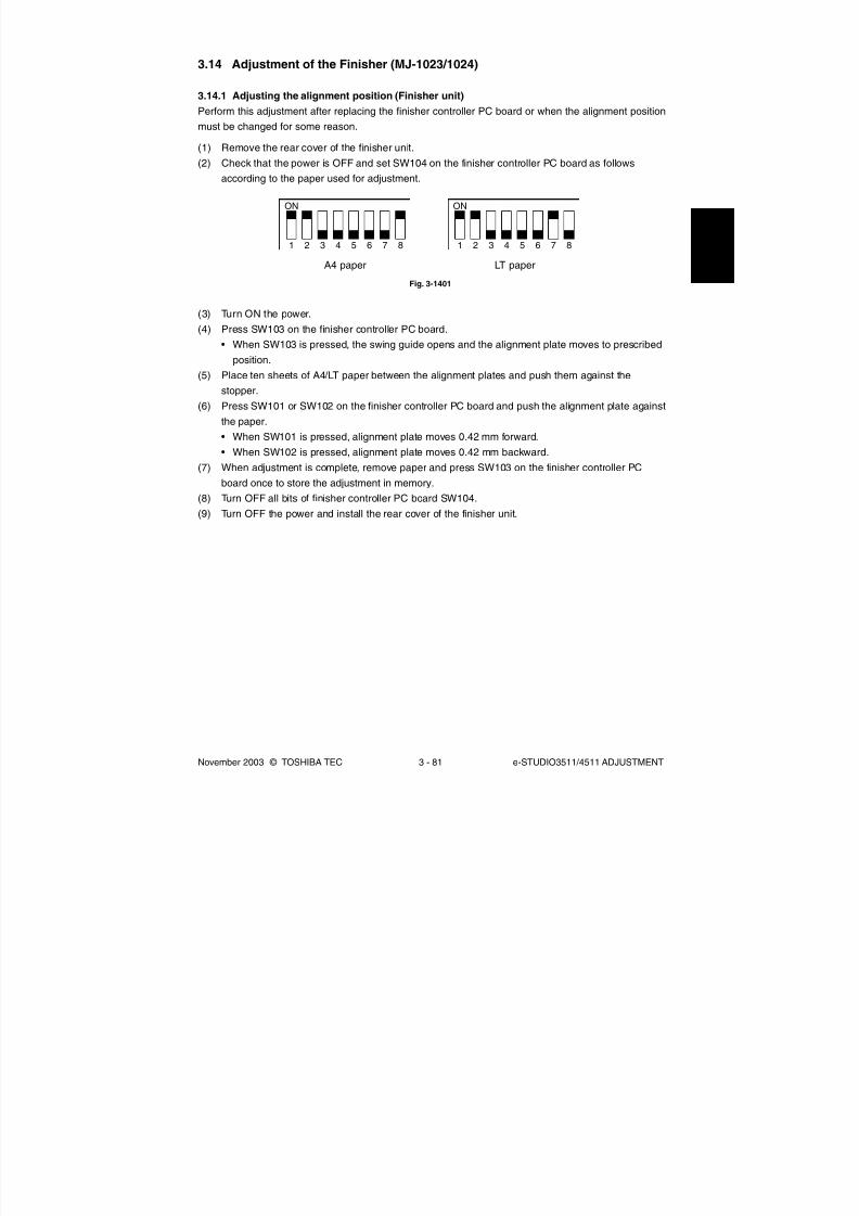
8/2/2019 ES-3511 Service Handbook
http://slidepdf.com/reader/full/es-3511-service-handbook 271/543
November 2003 © TOSHIBA TEC 3 - 81 e-STUDIO3511/4511 ADJUSTMENT
ON
1 2 3 4 5 6 7 8
ON
1 2 3 4 5 6 7 8
A4 paper LT paper
3.14 Adjustment of the Finisher (MJ-1023/1024)
3.14.1 Adjusting the alignment position (Finisher unit)
Perform this adjustment after replacing the finisher controller PC board or when the alignment position
must be changed for some reason.
(1) Remove the rear cover of the finisher unit.(2) Check that the power is OFF and set SW104 on the finisher controller PC board as follows
according to the paper used for adjustment.
Fig. 3-1401
(3) Turn ON the power.
(4) Press SW103 on the finisher controller PC board.
• When SW103 is pressed, the swing guide opens and the alignment plate moves to prescribed
position.
(5) Place ten sheets of A4/LT paper between the alignment plates and push them against the
stopper.
(6) Press SW101 or SW102 on the finisher controller PC board and push the alignment plate against
the paper.
• When SW101 is pressed, alignment plate moves 0.42 mm forward.
• When SW102 is pressed, alignment plate moves 0.42 mm backward.(7) When adjustment is complete, remove paper and press SW103 on the finisher controller PC
board once to store the adjustment in memory.
(8) Turn OFF all bits of finisher controller PC board SW104.
(9) Turn OFF the power and install the rear cover of the finisher unit.

8/2/2019 ES-3511 Service Handbook
http://slidepdf.com/reader/full/es-3511-service-handbook 272/543

8/2/2019 ES-3511 Service Handbook
http://slidepdf.com/reader/full/es-3511-service-handbook 273/543
November 2003 © TOSHIBA TEC 3 - 83 e-STUDIO3511/4511 ADJUSTMENT
(7) Verify the staple position. If any adjustment is needed, proceed to the step 8). If no adjustment is
needed, proceed to the step 9).
(8) Press SW101 or SW102 on the finisher controller PC board to adjust the staple position.
• When SW101 is pressed, the staple position shifts 0.49 mm to the front side.
• When SW102 is pressed, the staple position shifts 0.49 mm to the rear side.
Repeat the steps 5) to 7).(9) After confirming that the staple position is adjusted correctly, place a sheet of paper between the
alignment plates and push it against the stopper and push the rear edge of the paper against the
rear alignment plate. Then press SW103 once. (Stapling is performed and the adjustment value
is stored in memory.)
• The staple position adjustment is completed.
(10) Turn OFF all bits of SW104 on the finisher controller PC board.
(11) Turn OFF the power and install the rear cover of the finisher unit.

8/2/2019 ES-3511 Service Handbook
http://slidepdf.com/reader/full/es-3511-service-handbook 274/543
e-STUDIO3511/4511 ADJUSTMENT 3 - 84 November 2003 © TOSHIBA TEC
3.14.3 Adjusting the folding position (Saddle stitcher unit)
The folding position is adjusted by changing setting of bits 6 through 8 of SW504 on the saddle stitcher
controller PC board to match the stitching position (adjusting the distance over which the paper positioning
plate is moved to the folding position from the stitching position).
If you have replaced the saddle stitcher controller PC board, be sure to set the new SW504 so that the
settings will be the same as those on the old SW504. Perform this adjustment if, for any reason, you
must change the folding position.
(1) Check that the power is OFF and separate the finisher from the host machine.
If the optional puncher unit is installed, remove it from the finisher.
(2) Remove the PC board cover and set bits 1 through 4 of SW504 on the saddle stitcher controller
PC board as follows:
ON
1 2 3 4 5 6 7 8
Do not change bits 5 through 8.Fig. 3-1403
(3) Remove the rear cover, open the inlet cover of the saddle stitcher unit and tape the actuator of
inlet cover sensor (PI9) and inlet door switch (SW1).
(4) Before inserting the paper, mark the top of the paper. You will be using two sheets of A3 or LD
paper.
Mark
A3/LD paper
Insert direction
Fig. 3-1404

8/2/2019 ES-3511 Service Handbook
http://slidepdf.com/reader/full/es-3511-service-handbook 275/543
November 2003 © TOSHIBA TEC 3 - 85 e-STUDIO3511/4511 ADJUSTMENT
(5) Turn ON the power.
(6) Press SW1 on the saddle stitcher controller PC board so that the feed motor (M1) starts to rotate.
(Press SW1 three seconds or more if LD paper is used.)
(7) Open the inlet cover and insert two sheets of paper. Push them in by hand until the front edge of
the sheets push against the paper positioning plate.
(8) Close the inlet cover.
(9) Press SW1 on the saddle stitcher controller PC board.
• The saddle stitcher unit will “stitch” the sheets, and fold and deliver the stack automatically.
(10) Measure the distance (L) between the stitching position and the folding position. Then perform
“positive width adjustment” or “negative width adjustment” to suit the relationship between the
stitching position and the folding position.
• If the stitching position is below the folding position, perform “positive width adjustment.”
• If the stitching position is above the folding position, perform “negative width adjustment.”
Fig. 3-1405
Mark
Folding position
Stitching position
Unit: mm
Example: If L is 1 mm, provide "+1 mm".
Positive Width Adjustment Negative Width Adjustment
Mark
L
L Stitching position
Folding position
Unit: mm
Example: If L is 0.5 mm, provide "-0.5 mm".
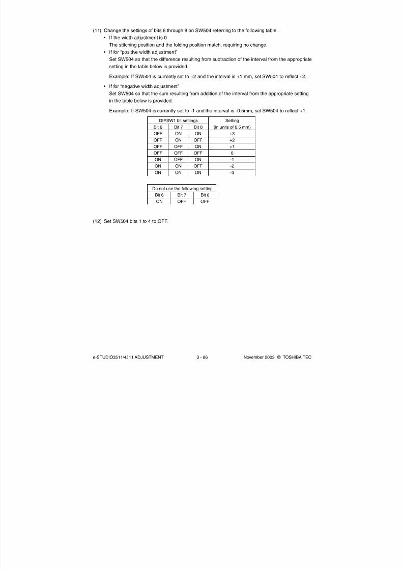
8/2/2019 ES-3511 Service Handbook
http://slidepdf.com/reader/full/es-3511-service-handbook 276/543
e-STUDIO3511/4511 ADJUSTMENT 3 - 86 November 2003 © TOSHIBA TEC
(11) Change the settings of bits 6 through 8 on SW504 referring to the following table.
• If the width adjustment is 0
The stitching position and the folding position match, requiring no change.
• If for “positive width adjustment”
Set SW504 so that the difference resulting from subtraction of the interval from the appropriate
setting in the table below is provided.
Example: If SW504 is currently set to +2 and the interval is +1 mm, set SW504 to reflect - 2.
• If for “negative width adjustment”
Set SW504 so that the sum resulting from addition of the interval from the appropriate setting
in the table below is provided.
Example: If SW504 is currently set to -1 and the interval is -0.5mm, set SW504 to reflect +1.
DIPSW1 bit settings
Bit 6 Bit 7 Bit 8
OFF ON ON
OFF ON OFF
OFF OFF ON
OFF OFF OFF
ON OFF ON
ON ON OFF
ON ON ON
Setting
(in units of 0.5 mm)
+3
+2
+1
0
-1
-2
-3
Do not use the following setting
Bit 6 Bit 7 Bit 8
ON OFF OFF
(12) Set SW504 bits 1 to 4 to OFF.

8/2/2019 ES-3511 Service Handbook
http://slidepdf.com/reader/full/es-3511-service-handbook 277/543
November 2003 © TOSHIBA TEC 3 - 87 e-STUDIO3511/4511 ADJUSTMENT
Fig. 3-1407
(3) Turn ON the power.(4) Press SW602 on the punch controller PC board. Sensor output is adjusted automatically when
the switch is pressed.
• Adjustment is complete if LED601 and LED602 on the punch controller PC board blinks
alternately.
(5) Press SW602 or SW603 on the punch controller PC board to end the adjustment mode and set
all bits of SW601 to OFF.
(6) Turn OFF the power.
ON
1 2 3 4
3.14.5 Sensor output adjustment (Puncher unit)
Perform this adjustment when replacing the punch controller PC board, transmittance sensor (photosensor
PC board/LED PC board), or deflection sensor (scrap full detector PC board unit).
(1) Check that the power is OFF and then remove the rear cover of the puncher.
(2) Set SW601 on the punch controller PC board as shown below.
3.14.4 Fine adjustment of binding/folding position (Saddle stitcher unit)
The binding position/folding position can be adjusted in the following (05) codes.
Code Paper size
468-0 A4-R / LT-R
468-1 B4
468-2 A3 / LD
Remarks
When the value increases, the binding/folding position shifts toward
the right page. (0.25mm/step)
Acceptable values: -14 to 14 (Default: 0)
Increase the adjustment value when the sheet of paper which has exited is "A".
Decrease the adjustment value when the sheet of paper which has exited is "B".
A: When the upper side of the folding
is longer than the lower side
B: When the upper side of the folding is
shorter than the lower side
← Paper feeding direction ← Paper feeding direction
Fig. 3-1406

8/2/2019 ES-3511 Service Handbook
http://slidepdf.com/reader/full/es-3511-service-handbook 278/543
e-STUDIO3511/4511 ADJUSTMENT 3 - 88 November 2003 © TOSHIBA TEC
Number of punch holes LED601/LED602
2 hole (E) Blinks 1 times per cycle
2/3 hole (N) Blinks 2 times per cycle
4 hole (F) Blinks 3 times per cycle
4 hole (S) Blinks 4 times per cycle
Fig. 3-1408
(3) Turn ON the power.
(4) Press SW602 on the punch controller PC board to select the number of punch holes.
• The items in the following table are displayed repeatedly from top to bottom each time SW602is pressed.
3.14.6 Registering the number of punch holes (Puncher unit)
This operation registers which puncher unit is attached to the IC on the punch driver PC board so that
the puncher unit can be identified by the finisher. For this reason, this operation must be performed
when the punch driver PC board has been replaced.
(1) Check that the power is OFF and then remove the rear cover of the puncher.
(2) Set SW601 on the punch controller PC board as shown below.
ON
1 2 3 4
(5) Press SW603 on the punch controller PC board. The number of punch holes is registered to the
punch controller PC board each time the switch is pressed.
• Registration is complete if LED601 and LED602 on the punch controller PC board blinks
alternately.
(6) Press SW602 or SW603 on the punch controller PC board to end the adjustment mode and set
all bits of SW601 to OFF.
(7) Turn OFF the power.

8/2/2019 ES-3511 Service Handbook
http://slidepdf.com/reader/full/es-3511-service-handbook 279/543
November 2003 © TOSHIBA TEC 3 - 89 e-STUDIO3511/4511 ADJUSTMENT
3.15 Key Copy Counter (MU-8, MU-10)
To make a key copy counter available, the following 2 components must be installed to the equipment.
Counter socket
MU-10
Key copy counter
MU-8
<Installation procedure>
(1) Take off the right upper cover.
(2) Open the bypass tray, ADU, jam access
cover and fuser unit cover. Take off the IH
terminal cover.
(3) Take off the right rear cover, and cut open
the window for the key copy counter.
(4) Pull out the harness connector from the hole
of the machine frame, and cut the short
harness of the connector. (Treat the cut
harness properly to avoid it causing a short
circuit with the machine frame.) Then,
disconnect the dummy connector.
Right upper cover
Right rear cover
Dummy connector
Harness connector
Fig. 3-1501
Fig. 3-1502
Fig. 3-1503
IH terminal
cover
04/09

8/2/2019 ES-3511 Service Handbook
http://slidepdf.com/reader/full/es-3511-service-handbook 280/543
e-STUDIO3511/4511 ADJUSTMENT 3 - 90 November 2003 © TOSHIBA TEC
(5) Connect the connector of the counter socket
to the harness connector of the equipment
side.
(6) Install the counter socket to the machine frame
with two M3 screws.
(7) Reattach the covers.
(9) Key in the value “3” in the setting mode (08-
222).
(8) Insert the key copy counter with its arrow mark
pointing the rear side of the equipment.
Screw
Counter socket
Harness connector
Key copy counter
Fig. 3-1504
Fig. 3-1505

8/2/2019 ES-3511 Service Handbook
http://slidepdf.com/reader/full/es-3511-service-handbook 281/543
November 2003 © TOSHIBA TEC 4 - 1 e-STUDIO3511/4511 PREVENTIVE MAINTENANCE
4. PREVENTIVE MAINTENANCE (PM)
4.1 PM Support Mode
4.1.1 General description
The timing for the parts replacement usually depends on the number of output pages / develop counts
after they were replaced before. However, the life span of them changes depending on the general
use of users and the environment in which the equipment is placed. Therefore, it is necessary to
consider not only the number of output pages but also the drive counts when deciding the timing for
the parts replacement in order to utilize the parts and materials effectively.
In addition, the drum rotates 4 times at color modes to transfer the images of 4 colors on the transfer
belt, overlaying one after another. Therefore, the number of output pages is counted as “4” for 1 page
for printing at color mode.
This equipment has the PM support mode, which makes it possible to see the general use of each
part (the number of output pages, develop counts and drive counts) and replacement record and to do
a counter clearing operation more efficiently when replacing.
The replacement record can be printed out in the list printing mode (9S-103).
4.1.2 Operational flow and operational screen
(1) Operational flow
* The screen goes back to the main screen when the counter clear is performed or the [CANCEL] button is
pressed after moving from the main screen, while it goes back to the sub screen after moving from the sub
screen.
Fig. 4-101
PM support mode activated
[6]+[START]+[POWER]ON
Main screen
Main unit list displayed
Sub screen
Sub unit list displayed
Clear screen
Counter clearconfirmation displayed
Counter clear performed
[RETURN]pressed
[CANCEL] pressed
[RETURN] pressed
[CANCEL]pressed
[INITIALIZE]pressed
Sub unit chosen[RESET] pressed
Clear finished
Clear finished
Main unit chosen
[RESET]
Main unit chosen[SUB UNIT] pressed
[2] [START]

8/2/2019 ES-3511 Service Handbook
http://slidepdf.com/reader/full/es-3511-service-handbook 282/543
e-STUDIO3511/4511 PREVENTIVE MAINTENANCE 4 - 2 November 2003 © TOSHIBA TEC
(2) Operational screen
(a) Main screen
Fig. 4-102
Displaying of the main unit name
Back to the PM support mode activation screen
Clearing of the chosen unit counters (all the sub unit (parts) counters belonging to that unit)
All counters are cleared when the unit is not selected
Moving to the sub screen
Moving to the next/previous page
Displaying of the standard number of output pages / develop counts (x1,000) to replace the
unit parts
Displaying of the present drive counts (x1,000)“∗” is displayed next to the present number when the number of drive counts has exceeded
its PM standard number.
Displaying of the standard number of drive counts (x1,000) to replace the unit parts
Displaying of the present number of output pages/develop counts (x1,000)
When there are differences among the sub units (parts), “_” is displayed and “CHECK
SUBUNIT” is displayed at the top
“∗” is displayed next to the present number when the number of output pages or develop
counts has exceeded its PM standard number.
Displaying of the number of output pages / develop counts (Page/D. cnt), drive counts (Cnt.)
and previous replacement date (Chg.) for a chosen unitWhen the replacement date for the sub unit is different, press the [SUB UNIT] button to
move to the sub screen and see each information, otherwise information is not displayed
Notes:
1. “—” is always displayed at the drive counts section for the reversing automatic document
feeder (RADF) and feed unit.
2. “—” is displayed at the numeric section for the paper source which is not installed since the
paper source is different depending on the structure of options.
1
2 3 4 5 6
910
7 8

8/2/2019 ES-3511 Service Handbook
http://slidepdf.com/reader/full/es-3511-service-handbook 283/543
November 2003 © TOSHIBA TEC 4 - 3 e-STUDIO3511/4511 PREVENTIVE MAINTENANCE
1
2 3 4 5 6
9
7 8
(b) Sub screen
Fig. 4-103
Displaying of the sub unit (parts) name
Back to the main screen
Clearing of the chosen sub unit (parts) counters
Moving to the next/previous page
Displaying of the present number of output pages / develop counts (x1,000)
“∗” is displayed next to the present number when the number of output pages or develop
counts has exceeded its PM standard number.
Displaying of the standard number of output pages / develop counts (x1,000) to replace the
sub unit (parts)
Displaying of the present drive counts (x1,000)“∗” is displayed next to the present number when the number of drive counts has exceeded
its PM standard number.
Displaying of the standard number of drive counts (x1,000) to replace the sub unit (parts)
Displaying of the number of output pages, develop counts and drive counts and previous
replacement date for a chosen sub unit

8/2/2019 ES-3511 Service Handbook
http://slidepdf.com/reader/full/es-3511-service-handbook 284/543
e-STUDIO3511/4511 PREVENTIVE MAINTENANCE 4 - 4 November 2003 © TOSHIBA TEC
Main screen Sub screen
Drum/cleaner unit Drum [DRUM]
[CLEANER/DRUM] Drum cleaning blade [DRUM BLADE]Drum cleaner brush [DRUM BRUSH]
Main charger unit Main charger grid [GRID][MAIN CHARGER] Main charger wire [MAIN CHARGER WIRE]
Main charger wire pad [WIRE CLEANING PAD]
Ozone filter Ozone filter [OZONE FILTER][FILTER]
Black developer unit Developer material K [BLACK DEVELOPER][BLACK DEVELOPER]
Color developer unit Developer material Y [YELLOW DEVELOPER][COLOR DEVELOPER] Developer material M [MAGENTA DEVELOPER]
Developer material C [CYAN DEVELOPER]
Transfer belt unit 1st transfer roller [1st TRANSFER ROLLER][1st TRANSFER] Transfer belt [TRANSFER BELT]
Transfer belt cleaning blade [BELT BLADE]
2nd transfer roller unit 2nd transfer roller [2nd TRANSFER ROLLER][2nd TRANSFER]
Fig. 4-104
When the [INITIALIZE] button is pressed, “Present number of output pages/develop counts”
and Present driving counts” are cleared and “Previous replacement date” is updated.
(3) Access tree
Note:
The name inside [ ] is displayed on the LCD screen.
1
(c) Clear screen

8/2/2019 ES-3511 Service Handbook
http://slidepdf.com/reader/full/es-3511-service-handbook 285/543
November 2003 © TOSHIBA TEC 4 - 5 e-STUDIO3511/4511 PREVENTIVE MAINTENANCE
Fuser unit Fuser belt [FUSER BELT][FUSER] Pressure roller [PRESS ROLLER]
Oil roller [OIL ROLLER]Cleaning roller [CLEANING ROLLER]Separation finger [PRESS ROLLER FINGER]Fuser belt guide [BELT GUIDE]
Scraper [PRESS ROLLER SCRAPER]
Upper drawer Pickup roller [PICK UP ROLLER(1st CST.)][1st CST.] Feed roller [FEED ROLLER(1st CST.)]
Separation roller [SEP ROLLER(1st CST.)]
Lower drawer Pickup roller [PICK UP ROLLER(2nd CST.)][2nd CST.] Feed roller [FEED ROLLER(2nd CST.)]
Separation roller [SEP ROLLER(2nd CST.)]
Bypass unit Pickup roller [PICK UP ROLLER(SFB)][SFB] Feed roller [FEED ROLLER(SFB)]
Separation roller [SEP ROLLER(SFB)]
RADF Pickup roller [PICK UP ROLLER(RADF)][RADF] Feed roller [FEED ROLLER(RADF)]
Separation roller [SEP ROLLER(RADF)]
LCF Pickup roller [PICK UP ROLLER(LCF)][LCF] Feed roller [FEED ROLLER(LCF)]
Separation roller [SEP ROLLER(LCF)]
PFP upper drawer Pickup roller [PICK UP ROLLER(3rd CST.)][3rd CST.] Feed roller [FEED ROLLER(3rd CST.)]
Separation roller [SEP ROLLER(3rd CST.)]
PFP lower drawer Pickup roller [PICK UP ROLLER(4th CST.)][4th CST.] Feed roller [FEED ROLLER(4th CST.)]
Separation roller [SEP ROLLER(4th CST.)]
Note:
When the counter value of any of the pickup roller, feed roller and separation roller in each unit is
reset, the value of the feeding retry counter is also reset simultaneously. When the [RESET] button
is pressed after selecting the feed unit in the Main Screen, the value of the feeding retry counter is
also reset simultaneously.
The feeding retry counter:
- Upper drawer Reset the feeding retry counter (08-1390)
- Lower drawer Reset the feeding retry counter (08-1391)
- PFP upper drawer Reset the feeding retry counter (08-1392)
- PFP lower drawer Reset the feeding retry counter (08-1393)
- Bypass unit Reset the feeding retry counter (08-1394)
- LCF Reset the feeding retry counter (08-1395)
04/05

8/2/2019 ES-3511 Service Handbook
http://slidepdf.com/reader/full/es-3511-service-handbook 286/543
e-STUDIO3511/4511 PREVENTIVE MAINTENANCE 4 - 6 November 2003 © TOSHIBA TEC
4.1.3 Work flow of parts replacement
The timing for the parts replacement usually depends on the number of output pages / develop counts
after they were replaced before. However, its drive counts is also to be considered when replacing the
parts. Even if the number of output pages has reached the level of replacement, for instance, the part
may still be usable with its drive counts not reaching the specified drive counts. On the other hand, the
part may need replacement even if the number of output pages has not reached the level of replacement
with its driving time exceeding the specified drive counts. The life span of some parts such as feed rolleris heavily dependent on the number of output pages rather than the drive counts.
The following work flow diagram shows how to judge the timing of replacement with the number of output
pages and the drive counts.
The number of output pages is counted as “4” for 1 page for printing at color modes. This “4” is “develop
counts”.
Example 1:
When the number of output pages has reached the specified level
Fig. 4-105
Example 2:
When the image failure occurred before the number of output pages has reached the specified level
Yes
No
• The parts in RADF
• The parts in feeding system
Replace the part.
•The parts in the drum/cleaner unit
• The parts in the transfer belt unit• The parts in the 2nd transfer unit
• Developer material
• The parts in the fuser unit
Check the drive counts at PM
support mode.
Does it exceed the specified
drive counts?
Replace the part.
The part is still usable.
Replace the part after the drive counts
has reached the specified count.
Check the drive counts of all parts at PM support mode.
Does it exceed the specified drive count?
Check the part and equipment according to the “TROUBLESHOOTING”.
Replace the part.Yes
No
Fig. 4-106

8/2/2019 ES-3511 Service Handbook
http://slidepdf.com/reader/full/es-3511-service-handbook 287/543
November 2003 © TOSHIBA TEC 4 - 7 e-STUDIO3511/4511 PREVENTIVE MAINTENANCE
4.2 General Descriptions for PM Procedure
(1) Preparation
a. Ask the user about the current conditions of the equipment and note them down.
b. Before starting maintenance, make some sample copies and store them.
c. See the replacement record and check the parts to be replaced in the PM support mode (6S-
2) or list printing mode (9S-103).
6S-2 : [6]+[START]+[POWER]ON [2] [START]
9S-103: [9]+[START]+[POWER]ON [103] [START]
PM SUPPORT CODE LIST
10-20-'03 11:28
UNIT OUTPUT PAGES/ PM OUTPUT PAGE/ DRIVE COUNTS PM DRIVE COUNTS
DEVELOP COUNTS DEVELOP COUNTS
DRUM 22220 200000 30948 320000
DRUM BLADE 22220 200000 30948 320000
DRUM BRUSH 22220 200000 30948 320000
GRID 22220 200000 30948 320000
MAIN CHARGER WIRE 22220 200000 30948 320000
WIRE CLEANING PAD 22220 200000 30948 320000
Fig. 4-201
d. Turn OFF the power and make sure to unplug the equipment.
(2) Perform a preventive maintenance using the following checklist and illustrations. Refer to the
Service Manual if necessary.
(3) Plug in the equipment after the maintenance has been finished. Then turn ON the power and
make some copies to confirm that the equipment is working properly.
4.3 Operational Items in Overhauling
Overhaul each equipment with the following timing.
• e-STUDIO3511: When the number of develop counts has reached 360,000 or 2.5 years have passed
form the start of use (Whichever is earlier.)
• e-STUDIO4511: When the number of develop counts has reached 450,000 or 2.5 years have passed
form the start of use (Whichever is earlier.)
(1) Replace all the supplies.
(2) Check the components in the drive section (gears, pulleys, timing belts, etc.). Replace them with
new ones if they are damaged.
(3) Check all the adhesives such as tape and Mylar if they are damaged or have become unstuck.
Replace them with new ones if necessary.
(4) Check the performance of all the switches and sensors. Replace them with new ones if neces-
sary.
(5) Clean inside the equipment thoroughly.

8/2/2019 ES-3511 Service Handbook
http://slidepdf.com/reader/full/es-3511-service-handbook 288/543
e-STUDIO3511/4511 PREVENTIVE MAINTENANCE 4 - 8 November 2003 © TOSHIBA TEC
L Launa 40
Coating
SI Silicon oilW1 White grease
(Molykote X5-6020)
W2 White grease
(Molykote HP-300)
AV Alvania No.2
FL Floil
(GE-334C)
Notes:
1. Perform cleaning and lubricating in every 120,000 output pages for e-STUDIO3511, and every 150,000output pages for e-STUDIO4511. Lubricate the replacement parts following to the replacement cycle.
Exceptionally, the lubrication for the drum unit, main charger, color developer unit and 1st transfer
unit must follow the PM cycle of each unit.
2. Values under “Replacement” indicate the replacement cycle for e-STUDIO3511/e-STUDIO4511.
(KS= x 1,000 sheets, KD= x 1,000 developments)
3. The replacement cycle of the parts for the charge, development and 1st transfer in copying process
is not indicated by the number of output pages (sheet), but the develop counts (development). The
number of output pages is counted as “4 developments” for 1 page for printing at color mode, and “1
development” at black-and-white mode.
4. The replacement cycle of the parts in the feeding section equals to the number of sheets fed from
each paper source.5. Be careful not to put oil on the rollers, belts and belt pulleys when lubricating.
B. Laser unit
Replace-Items to check Cleaning
Lubri-ment
Operation Parts listRemarks
cation (KS) check <P-I>
A1. Original glass or A *a1
A2. ADF original glass *a1
A3. Mirror-1
A4. Mirror-2
A5. Mirror-3
A6. ReflectorA7. Lens
A8. Exposure lamp
A9. Automatic original detection sensor
A10. Slide sheet (front and rear) or A
B1. Slit glass
4.4 Preventive Maintenance Checklist
Symbols used in the checklist
Cleaning Lubrication Replacement Operation check Date
A Clean with alcohol
Clean with soft pad,
cloth or vacuum cleaner
The number of sheets
or developments
consumed beforereplacement
(Value x 1,000)
Replace if deformed
or damaged
After cleaning
or replacement,
confirm there isno problem.
User name
Serial No.
Inspector’sname
Remarks
Replace-Items to check Cleaning Lubri- ment Operation Parts list Remarks
cation (KS) check <P-I>
04/05
[Preventive Maintenance Checklist]
A. Scanner

8/2/2019 ES-3511 Service Handbook
http://slidepdf.com/reader/full/es-3511-service-handbook 289/543
November 2003 © TOSHIBA TEC 4 - 9 e-STUDIO3511/4511 PREVENTIVE MAINTENANCE
D1. Transport roller (upper, middle and A
lower)
D2. One side of the GCB bushing to L
which the shaft is inserted
D3. One side of the plastic bushing W1
to which the shaft is inserted
D4. Paper guide W
E. Bypass feed unit
F. Main charger
E1. Pickup roller 80/80 P22-I26
E2. Feed roller 80/80 P22-I37
E3. Separation roller AV, W2 80/80 P21-I1 *e1
E4. Bypass tray
E5. Drive gear (shaft) W1
E6. GCB bushing bearing L
E7. Transport roller A
Items to check
F1. Main charger case
F2. Main charger wire
F3. Contact point of terminals
F4. Charger wire cleaning pad
F5. Main charger grid
D. Automatic duplexing unit
C. Feed unit
C1. Pickup roller 80/80 P18-I20
C2. Feed roller 80/80 P18-I24
C3. Separation roller AV, V2 80/80 P18-I5 *c1C4. Transport roller A
C5 Paper guide
C6. Drive gear (tooth face and shaft) W1 *c2
C7. GCB bushing bearing L
C8. One side of the plastic bushing to W1
which the shaft is inserted
C9. Registration roller A
C10.Paper dust removal brush *c3
Replace-Items to check Cleaning
Lubri-ment
Operation Parts listRemarks
cation (KS) check <P-I>
Replace-Items to check Cleaning
Lubri-ment
Operation Parts listRemarks
cation (KS) check <P-I>
Replace-Items to check Cleaning Lubri- ment Operation Parts list Remarks
cation (KS) check <P-I>
CleaningReplace-
ment(KD)
160/200
160/200
160/200
Lubri-cation
Operationcheck
Parts list<P-I>
P28-I15
P28-I12
P28-I21
Remarks
*f1
*f1
04/02

8/2/2019 ES-3511 Service Handbook
http://slidepdf.com/reader/full/es-3511-service-handbook 290/543
e-STUDIO3511/4511 PREVENTIVE MAINTENANCE 4 - 10 November 2003 © TOSHIBA TEC
G. Drum/Cleaner related section
Note: Check the color deviation after replacing G1 and G4.
H. Toner bag
I. Black developer unit
Items to check
G1. Photoconductive drum
G2. Drum shaft
G3. Whole cleaner unit
G4. Drum cleaning blade
G5. Drum cleaner brush
G6. Recovery blade
G7. Used toner auger drive section
G8. Discharge LED
G9. Ozone filter
CleaningReplace-
ment(KD)
160/200
160/200
160/200
160/200
Lubri-cation
W1
Operationcheck
Parts list<P-I>
P103-I1
P32-I34
P32-I29
P14-I50
Remarks
Refer to
Chapter 4.8.2.
*g1
*g1
*g2
Items to check
H1. Toner bag
CleaningReplace-
ment(KD)
50/50
Lubri-cation
Operationcheck
Parts list<P-I>
P103-I6
Remarks
Items to check
I1. Whole black developer unit
I2. Black developer unit drive section
I3. Developer material (K)I4. Front shield
I5. Oil seal (6 pcs.)
I6. Guide roller
I7. Toner cartridge drive gear
I8. Side shield
Cleaning
or A
Replace-ment(KS)
120/150
360/450
Lubri-cation
W1
AV
W1
Operationcheck
Parts list<P-I>
P103-I2
P34-I3, 15
Remarks
*i1
*i2
04/10

8/2/2019 ES-3511 Service Handbook
http://slidepdf.com/reader/full/es-3511-service-handbook 291/543
November 2003 © TOSHIBA TEC 4 - 11 e-STUDIO3511/4511 PREVENTIVE MAINTENANCE
Items to check
J1. Whole color developer unit
(Y, M and C)
J2. Color developer unit drive section
(Y, M and C)
J3. Developer material (Y, M, and C)
J4. Front shield (Y, M and C)
J5. Oil seal (6 pcs. for each color)
J6. Guide roller (Y, M and C)
J7. Toner cartridge drive gear
(Y, M and C)
J8. Revolver drive gear
J9. Color auto-toner sensor
J10.Side shield
J11. Polarity adjustment plate
J12. Color toner cartridge sensor
Cleaning
or A
Replace-ment(KS)
30/37.5
360/450
Lubri-cation
W1
AV
W1
W1
AV
FL
Operationcheck
Parts list<P-I>
P103-I3
P33-I12, 14
P36-I104
Remarks
*j1
*j2
*j3
*j4
*j5
Parts list<P-I>
P30-I34
P30-I17
P31-I11
P31-I8
P31-I41
P31-I31
Remarks
*k1
*k1
*k2
*k3
*k4
Operationcheck
Replace-ment(KD)
480/600
480/600
160/200
160/200
160/200
160/200
Lubri-cation
Cleaning
A
A
Items to check
K1. Transfer belt
K2. 1st transfer roller
K3. Transfer belt drive roller 1
K4. Transfer belt drive roller 2
K5. Transfer belt cleaning blade
K6. Image quality sensor
K7. Transfer belt home position sensor
(2 pcs.)
K8. Transfer belt recovery blade
K9. Paper clinging detection sensor
K10. Blade seal (front side)
K11. Blade seal (rear side)
K12. Tape
J. Color developer unit / Revolver unit
K. Transfer belt unit
Note: Check the color deviation after replacing K1, K2 and K5.
L. 2nd transfer roller unit
L1. 2nd transfer roller 240/300 P13-I30
L2. Paper guide *l1
L3. Washer 240/300 P13-I49
Replace-Items to check Cleaning
Lubri-ment
Operation Parts listRemarks
cation (KS) check <P-I>
04/10
Note: Check the color deviation after replacing L1.

8/2/2019 ES-3511 Service Handbook
http://slidepdf.com/reader/full/es-3511-service-handbook 292/543
e-STUDIO3511/4511 PREVENTIVE MAINTENANCE 4 - 12 November 2003 © TOSHIBA TEC
M. Fuser unit
N. RADF (MR-3015)
M1. Fuser belt 120/150 P40-I1
M2. Pressure roller 120/150 P39-I5
M3. Separation finger 120/150 P39-I25 *m1M4. Oil roller 120/150 P40-I34
M5. Cleaning roller 120/150 P40-I23
M6. Thermistor (3 pcs.) A *m2
M7. Fuser unit drive gear W1
M8. Exit roller A
M9. Fuser belt guide 120/150 P41-I18
M10. Separation roller W2 *m3
M11. Scraper 120/150 P39-I55
N1. Pickup roller 120/120 P8-I26
N2. Feed roller 120/120 P8-I25
N3. Separation roller 120/120 P6-I6
N4. Original length sensor
N5. Registration roller A
N6. 1st small roller A
N7. 2nd small roller A
N8. Read sensor
N9. Read guide
N10.Read roller A
N11. 3rd small roller A
N12.4th small roller A
N13.Reverse sensor
N14.Exit roller A
N15.Reverse roller A
N16.Platen sheet or A
Replace-Items to check Cleaning Lubri- ment Operation Parts list Remarks
cation(KS)
check <P-I>
Replace-Items to check Cleaning Lubri- ment Operation Parts list Remarks
cation (KS) check <P-I>
04/02

8/2/2019 ES-3511 Service Handbook
http://slidepdf.com/reader/full/es-3511-service-handbook 293/543
November 2003 © TOSHIBA TEC 4 - 13 e-STUDIO3511/4511 PREVENTIVE MAINTENANCE
O. PFP (KD-1011)
O1. Pickup roller A 160/160 P4-I30
O2. Feed roller A 160/160 P4-I28
O3. Separation roller A 160/160 P5-I12
O4. Drive gear (tooth face) W1
P. LCF (KD-1012)
O1. Pickup roller (upper/lower) A 80/80 P5-I29
O2. Feed roller (upper/lower) A 80/80 P5-I26
O3. Separation roller (upper/lower) A AV, W2 80/80 P5-I12 *o1O4. Drive gear (tooth face) W1
Replace-Items to check Cleaning Lubri- ment Operation Parts list Remarks
cation (KS) check <P-I>
Replace-Items to check Cleaning Lubri- ment Operation Parts list Remarks
cation (KS) check <P-I>
04/02

8/2/2019 ES-3511 Service Handbook
http://slidepdf.com/reader/full/es-3511-service-handbook 294/543
e-STUDIO3511/4511 PREVENTIVE MAINTENANCE 4 - 14 November 2003 © TOSHIBA TEC
Fig. 4-202 Front side
A2 A4 A8 A6 A1
A9
A10A7A3A5
J9
J1J3J4J5J10J11
I1I3I4I5I8
E4
K4 K7K2
G3
M8 M3D1
D1
D1
E1
L1L3
K7
K3
C4
C2
C3C4
C5C1K1G8F1F3
F2F4
F5 B1
C2
C3
E2
E3
C9, C10
E7
M2
D4
L2
G9
M1
G5
G6G1
G7
G4M6
K6
M4
M5
K9
K12K11K10K5
M11
J12
04/05
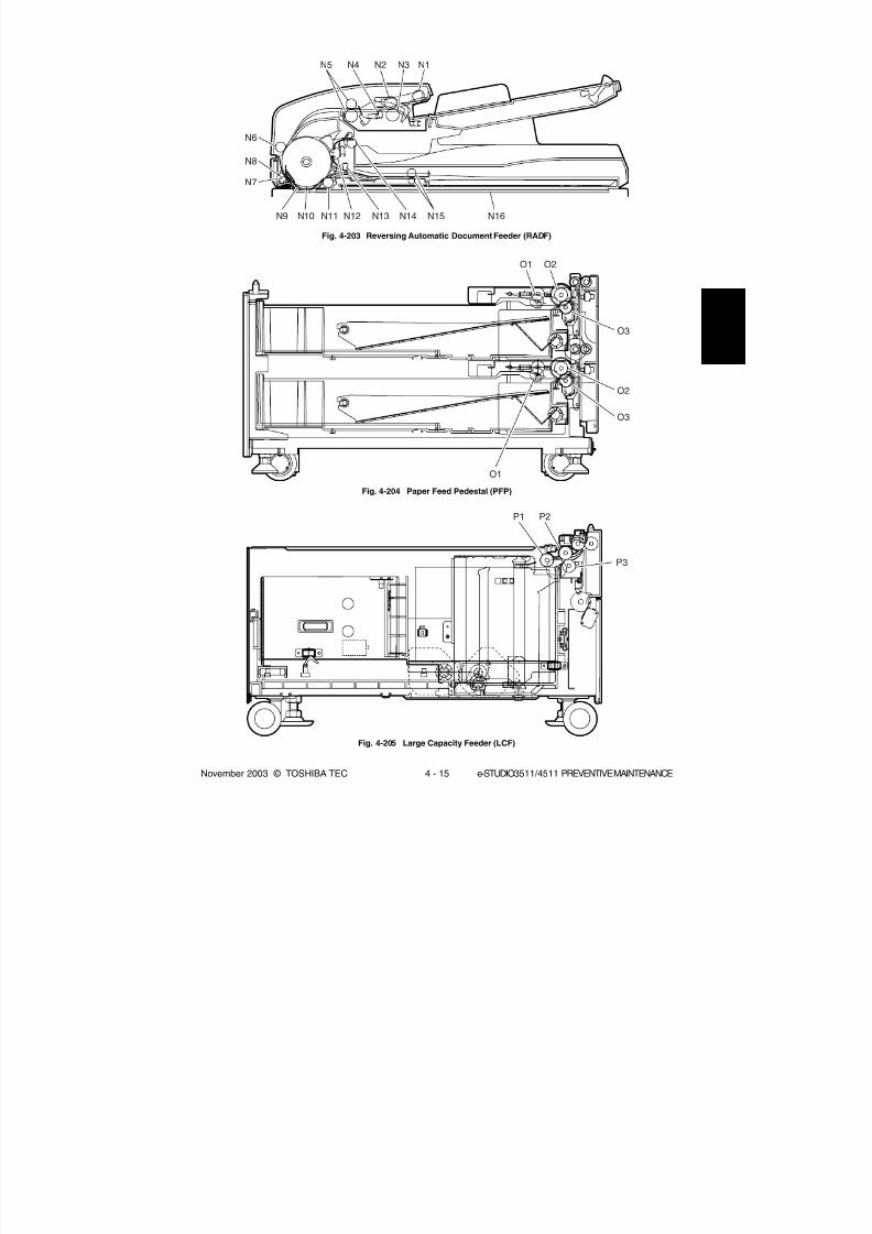
8/2/2019 ES-3511 Service Handbook
http://slidepdf.com/reader/full/es-3511-service-handbook 295/543
November 2003 © TOSHIBA TEC 4 - 15 e-STUDIO3511/4511 PREVENTIVE MAINTENANCE
Fig. 4-203 Reversing Automatic Document Feeder (RADF)
Fig. 4-204 Paper Feed Pedestal (PFP)
Fig. 4-205 Large Capacity Feeder (LCF)
O1 O2
O3
O3
O1
O2
P1 P2
P3
N5 N4
N6
N7
N8
N9 N10 N11 N12 N13 N14 N15 N16
N2 N3 N1

8/2/2019 ES-3511 Service Handbook
http://slidepdf.com/reader/full/es-3511-service-handbook 296/543
e-STUDIO3511/4511 PREVENTIVE MAINTENANCE 4 - 16 November 2003 © TOSHIBA TEC
Apply grease on the
inner surface
Apply white grease
Remarks “*” in the Preventive Maintenance Check List
*a1. Original glass, ADF original glass
Clean both sides of the original glass and ADF original. Make sure that there is no dust on the
mirrors-1, -2, -3 and lens after cleaning. Then install the original glass and ADF original glass.
Note:
Make sure that there is no fingerprints or oil staining on part of the original glass on where the
original scale is mounted since the shading correction plate is located below the scale to be
scanned.
*c1, o1. Separation roller (Feed unit, PFP)
Apply an even coat of grease (Alvania No.2) to all round the inside of the spring.
When replacing the separation roller, apply adequate amount of white grease (Molykote
HP-300) on the places of the holder shown in the figure (4 places).
Note:
Make sure that the grease does not adhere to the roller surface. Wipe it off with alcohol if
adhered.
*c2. Drive gears in the paper feeding section (teeth of gears and shafts)
Apply some white grease (Molykote X5-6020) to the teeth of gears and shafts of the drive gears.
Note:
Make sure that oil is not running over or scattered around as the gear is rotated coming into the
clutch after applying molykote to the gear which is located near the clutch. The quantity of
molycote should be smaller than that to be applied to the other parts.
Fig. 4-206 Fig. 4-207

8/2/2019 ES-3511 Service Handbook
http://slidepdf.com/reader/full/es-3511-service-handbook 297/543
November 2003 © TOSHIBA TEC 4 - 17 e-STUDIO3511/4511 PREVENTIVE MAINTENANCE
Apply grease on the
inner surfaceApply white grease
Fig. 4-208
*e1. Separation roller (SFB)
Apply an even coat of grease (Alvania No.2) to all round the inside of the spring.
When replacing the separation roller, apply adequate amount of white grease (Molykote
HP-300) on the places of the holder shown in the figure (4 places).
Note:
Make sure that the grease does not adhere to the roller surface. Wipe it off with alcohol if
adhered.
Fig. 4-209 Fig. 4-210
*c3. Install the 2nd transfer front guide after the cleaning of the paper dust removal brush.
Push the 2nd transfer front guide to the transfer belt unit and fix it securely as shown in the
figure below.

8/2/2019 ES-3511 Service Handbook
http://slidepdf.com/reader/full/es-3511-service-handbook 298/543
e-STUDIO3511/4511 PREVENTIVE MAINTENANCE 4 - 18 November 2003 © TOSHIBA TEC
Outside
Inside
Developer frame
(Nozzle mixer)
Grease
Oil seal
Fig. 4-211
*f1. Main charger case / Main charger wire
Clean the main charger case and wire with a cloth soaked in water and squeezed tightly, and
then wipe them with a dry cloth.
Note:
Be careful of the following when attaching a new wire (length: 373 mm).
• Insert the wire securely into the V-grooves of the front and rear sides.• Do not twist the wire.
• Do not touch the wire with your bare hand.
*g1. Drum cleaning blade / Drum cleaner brush
Since the edge of the blade is vulnerable and can be easily damaged by factors such as the
adherence of paper dust. Replace the cleaning blade and brush with new ones if poor images
are copied due to the damaged blade regardless of the number of output pages which have
been made.
*g2. Recovery bladeReplace the recovery blade regardless the number of output pages if the edge of the blade get
damaged.
*i1, j1. Developer material
After replacing the developer material, be sure to perform the auto-toner adjustment and then
image quality control initialization ( Chapter 3.2 ).
*i2. Oil seal (Black developer unit)
Mixer unit (Shafts of mixers-1 & -2) 4 pcs.
Developer sleeve 2 pc.
*j2. Oil seal (Color developer unit)
Mixer unit (Shafts of mixers-1 & -2) 4 pcs.
Developer sleeve 2 pc.
Note:
Lubricate the oil seal only when the oil seal is replaced.
During replacement, coat the oil seal with grease (Alvania No.2).
(1) Push in a new oil seal parallel to the mounting hole
section of the developer frame or outside of the nozzle
mixer.
* Pay attention to the direction in which the oil seal is
attached. (See figure on right.)
(2) Apply an even coat of grease to the inside of the oil
seal.
• Amount: About two small drops
(3) Wipe off any grease exuded from the inside.
04/05

8/2/2019 ES-3511 Service Handbook
http://slidepdf.com/reader/full/es-3511-service-handbook 299/543
November 2003 © TOSHIBA TEC 4 - 19 e-STUDIO3511/4511 PREVENTIVE MAINTENANCE
Head of color auto-toner sensor
Color auto-toner
sensor unit Reference plate
Color auto-toner
sensor unit
*j3. Color auto-toner sensor
The head of color auto-toner sensor is to be cleaned with a cotton swab or soft cloth with
sufficient alcohol filled in. The reference plate is to be cleaned by blowing off the adhered toner
with an air-spray type cleaner such as a blower brush or an air duster.
During replacement, coat the shaft of sensor shutter with the grease (Alvania No.2).
Fig. 4-212
Note:
Never clean the reference plate by touching it directly (e.g. brushing away the dust) since the
surface of reference plate will be scratched.
*j4. Polarity adjustment plate
Apply two-rice-grain-amount of FLOIL (GE-334C) to the polarity adjustment plate (feeding ter-
minal).
04/05
Fig. 4-213
*j5. Color toner cartridge sensor
Perform the cleaning of the surface of the color toner cartridge sensor when you replace the
color developer unit (e-STUDIO3511: 30,000 sheets / e-STUDIO4511: 37,500 sheets).

8/2/2019 ES-3511 Service Handbook
http://slidepdf.com/reader/full/es-3511-service-handbook 300/543
e-STUDIO3511/4511 PREVENTIVE MAINTENANCE 4 - 20 November 2003 © TOSHIBA TEC
Fig. 4-215
*k4. Transfer belt recovery blade
Clean the surface of transfer belt recovery blade with a cloth soaked in water and tightly squeezed,
and the wipe it with a dry cloth when replacing the transfer belt cleaning blade.
If the edge of recovery blade is damaged, replace the blade regardless of the number of output
pages.
Fig. 4-214
*k2. Area around image quality sensor
Clean the shutter of the image quality sensor and around it. Do not touch the sensor head inside
the shutter.
*k3. Transfer belt home position sensorClean each surface of transfer belt home position sensors (2 pcs.) with a dry cloth when replac-
ing the transfer belt.
Blot
04/05
*k1. Transfer belt drive roller -1, -2
Fully clean up the toner and such adhered to the roller with alcohol since an image failure may
occur if there are any bolts remaining on the roller.

8/2/2019 ES-3511 Service Handbook
http://slidepdf.com/reader/full/es-3511-service-handbook 301/543
November 2003 © TOSHIBA TEC 4 - 21 e-STUDIO3511/4511 PREVENTIVE MAINTENANCE
Fig. 4-216
Fig. 4-217
*m1. Separation finger
The paper jam may be caused if the tip of the finger is damaged or deformed. If there is any
problem with it, replace the finger with a new one regardless of the number of output pageswhich have been made. Do not damage the tip of the finger during the cleaning. The finger may
be damaged if the toner adhering to the tip of it is scraped off forcibly. Replace the finger if the
toner is sticking to it heavily.
*l1. Paper guide
Clean the surface of the paper guide (denoted in the figure) with a piece of dry cloth.
When cleaning, do not touch the surface of the transfer belt with bare hands.
*k5. Paper clinging detection sensor
Open the ADU and clean the paper clinging detection sensor with a cotton swab, etc.
Note:
Clean the entire area (denoted in the figure below) of the sensor surface.
04/05

8/2/2019 ES-3511 Service Handbook
http://slidepdf.com/reader/full/es-3511-service-handbook 302/543
e-STUDIO3511/4511 PREVENTIVE MAINTENANCE 4 - 22 November 2003 © TOSHIBA TEC
*m2. Thermistor
Clean the thermistor with alcohol if the toner or dirt is sticking to it when the fuser roller is
replaced. Do not deform or damage the thermistor during the cleaning. Replace the thermistor
with a new one if it is damaged or deformed regardless of degree.
*m3. Separation roller
When replacing the transfer belt, apply some White Molykote (HP-300) on both ends of the
separation roller shaft.
Fig. 4-218
04/05

8/2/2019 ES-3511 Service Handbook
http://slidepdf.com/reader/full/es-3511-service-handbook 303/543
November 2003 © TOSHIBA TEC 4 - 23 e-STUDIO3511/4511 PREVENTIVE MAINTENANCE
Part name
BL-3511D
WIRE-CHARGR-373
GRID-220
B-3511
FILTER-OZ-SPB-600
ASYS-PAD-CHARGR-350
D-3511-Y
D-3511-M
D-3511-C
JIG-CLEAN-DOC
BT-3511TR
BL-3511TR
CR-3511TR
SEAL-BLADE-FRT
SEAL-BLADE-RER
TAPE-2191FR
D-3511-K
JIG-CLEAN-DOC
CR-3511TR2
WSH-4P5-8-OP3-PHF850S
BT-3511-FU
HR-3511-L
SCRAPR-FUS-350
SR-3511U
B-3511U
COLAR-HR-IN
ASYB-BRKT-SCRAPR
ROLLER-PICK-AT
K-ROLL-FEED
K-ROLL-SPT
ROL-PICK-UP
ROL-PAPER-FED-F
ROL-PAPER-FED-S
ROL-PICK-UP
ROL-FEED
ROL-SPT-513
Qty.
1
1
1
1
1
1
1
1
1
1
1
1
1
1
1
1
1
1
1
4
1
1
5
1
1
2
1
1
1
1
1
1
1
1
1
1
Item
EPU-KIT-3511
DEV-KIT-3511C
TBU-KIT-3511
DEV-KIT-3511
FR-KIT-3511
ROL-KIT-16CST
ROL-KIT-1010
DF-KIT-3015
Product name
Drum cleaning blade
Main charger wire
Main charger grid
Drum cleaner brush
Ozone filter
Charger wire cleaning pad
Developer material (Y)
Developer material (M)
Developer material (C)
Cleaning jig
Transfer belt
Transfer belt cleaning blade
1st transfer roller
Blade seal (front side)
Blade seal (rear side)
Tape
Developer material (K)
Cleaning jig
2nd transfer roller
Washer
Fuser belt
Pressure roller
Separation finger
Oil roller
Cleaning roller
Fuser belt guide
Scraper
Pick up roller
Feed roller
Separation roller
Pick up roller
Feed roller
Separation roller
Pick up roller
Feed roller
Separation roller
4.5 PM KIT
04/02
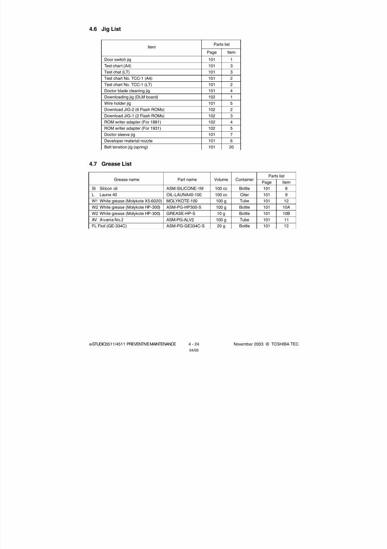
8/2/2019 ES-3511 Service Handbook
http://slidepdf.com/reader/full/es-3511-service-handbook 304/543
e-STUDIO3511/4511 PREVENTIVE MAINTENANCE 4 - 24 November 2003 © TOSHIBA TEC04/05
4.6 Jig List
Item
Door switch jig
Test chart (A4)
Test chat (LT)
Test chart No. TCC-1 (A4)
Test chart No. TCC-1 (LT)
Doctor blade cleaning jig
Downloading jig (DLM board)
Wire holder jig
Download JIG-2 (6 Flash ROMs)
Download JIG-1 (2 Flash ROMs)
ROM writer adapter (For 1881)
ROM writer adapter (For 1931)
Doctor sleeve jig
Developer material nozzle
Belt tenstion jig (spring)
Page
101
101
101
101
101
101
102
101
102
102
102
102
101
101
101
Item
1
3
3
2
2
4
1
5
2
3
4
5
7
6
20
4.7 Grease List
Grease name
SI Sil icon oil
L Launa 40
W1 White grease (Molykote X5-6020)
W2 White grease (Molykote HP-300)
W2 White grease (Molykote HP-300)
AV Alvania No.2
FL Floil (GE-334C)
Page
101
101
101
101
101
101
101
Parts list
Item
8
9
12
10A
10B
11
13
Part name
ASM-SILICONE-1M
OIL-LAUNA40-100
MOLYKOTE-100
ASM-PG-HP300-S
GREASE-HP-S
ASM-PG-ALV2
ASM-PG-GE334C-S
Volume
100 cc
100 cc
100 g
100 g
10 g
100 g
20 g
Container
Bottle
Oiler
Tube
Bottle
Bottle
Tube
Bottle
Parts list

8/2/2019 ES-3511 Service Handbook
http://slidepdf.com/reader/full/es-3511-service-handbook 305/543
November 2003 © TOSHIBA TEC 4 - 25 e-STUDIO3511/4511 PREVENTIVE MAINTENANCE
4.8 Precautions for Storing and Handling Supplies
4.8.1 Precautions for storing TOSHIBA supplies
A. Toner/Developer
Toner and developer should be stored in a place where the ambient temperature is between
10°C to 35°C (no condensation), and should also be protected against direct sunlight during
transportation.
B. Photoconductive drum
Like the toner and developer, photoconductive drum should be stored in a dark place where the
ambient temperature is between 10°C to 35°C (no condensation). Be sure to avoid places where
drums may be subjected to high humidity, chemicals and/or their fumes.
C. Drum cleaning blade / Transfer belt cleaning blade
This item should be stored in a flat place where the ambient temperature is between 10°C to 35°C,
and should also be protected against high humidity, chemicals and/or their fumes.
D. Transfer belt / Transfer roller / Fuser belt / Pressure roller
Avoid places where the rollers may be subjected to high humidity, chemicals and/or their fumes.
E. Oil roller / Cleaning roller
Avoid places where the rollers may be subjected to high humidity, chemicals and/or their fumes.
They should also be stored “horizontally” on a flat surface.
F. Paper
Avoid storing copy paper in places where it may be subjected to high humidity.
After a package is opened, be sure to place and store it in a storage bag.

8/2/2019 ES-3511 Service Handbook
http://slidepdf.com/reader/full/es-3511-service-handbook 306/543
e-STUDIO3511/4511 PREVENTIVE MAINTENANCE 4 - 26 November 2003 © TOSHIBA TEC
4.8.2 Checking and cleaning of photoconductive drum
(1) Use of gloves
If fingerprints or oil adhere to the drum surface, the property of the photosensitive drum may
degrade, affecting the quality of the copy image. So, do not touch the drum surface with bare
hands.
(2) Handling precautions
As the photoconductive drum surface is very sensitive, be sure to handle the drum carefully
when installing and removing it so as not damage its surface.
Be sure to apply “patting powder” (lubricant) to the entire surface of the drum (including both ends
of the drum where OPC is not coated) when replacing the drum. When the drum has been replaced
with a new one, the drum counter (setting mode (08-1150-0, 3, 6 and 7) must be cleared to 0 (zero).
This clearing can be performed in PM support mode.
Notes:
1. Application of the patting powder is for reducing the friction between the drum and cleaning
blade. If the application of patting powder is neglected, the drum and cleaning blade may bedamaged.
2. When paper fibers or dint adhere to the cleaning blade edge, they may reduce the cleaning
efficiency and, in addition, may damage the blade and the drum. Be sure to remove any fibers
found adhering to the blade.
(3) Installation of equipment and storage of drum
Avoid installing the equipment where it may be subjected to high temperature, high humidity,
chemicals and/or their fumes.
Do not place the drum in a location where it is exposed to direct sunlight or high intensity light
such as near a window. Otherwise the drum will fatigue, and will not produce sufficient imagedensity immediately after being installed in the equipment.
(4) Cleaning the drum
At periodic maintenance calls, wipe the entire surface of the drum clean using the designated
cleaning cotton. Use sufficiently thick cleaning cotton (dry soft pad) so as not to scratch the drum
surface inadvertently with your fingertips or nails. Also, remove your rings and wristwatch before
starting cleaning work to prevent accidental damage to the drum.
Do not use alcohol, selenium refresher and other organic solvents or silicon oil as they will have
an adverse effect on the drum.
(5) Scratches on photoconductive drum surface
If the surface is scratched in such a way that the aluminum substrate is exposed, no copy image will
be produced on this area. In addition, the cleaning blade will be damaged so replacement with a
new drum will be necessary.
(6) Collecting used photoconductive drums
Regarding the recovery and disposal of used photoconductive drums, we recommend following the
relevant local regulations or rules.

8/2/2019 ES-3511 Service Handbook
http://slidepdf.com/reader/full/es-3511-service-handbook 307/543
November 2003 © TOSHIBA TEC 4 - 27 e-STUDIO3511/4511 PREVENTIVE MAINTENANCE
4.8.3 Checking and cleaning of drum cleaning blade and transfer belt cleaning blade
(1) Handling precautions
Pay attention to the following points as the cleaning blade life is determined by the condition of its
edge:
• Do not allow hard objects to hit or rub against blade edge.
• Do not rub the edge with a cloth or soft pad.
• Do not leave oil (or fingerprints, etc.) on the edge.
• Do not apply solvents such as paint thinner to the blade.
• Do not allow paper fibers or dirt to contact the blade edge.
• Do not place the blade near a heat source.
(2) Cleaning procedure
Clean the blade edge with a cloth moistened with water and squeezed lightly.
4.8.4 Handling of drum cleaner brush
Do not touch the brush surface with bare hands.
4.8.5 Handling of transfer belt
(1) Do not touch the transfer belt surface with bare hands.
(2) Prevent oil or other foreign matter from adhering to the transfer belt surface.
(3) Do not touch the transfer belt with alcohol or any other organic solvent.
(4) Do not apply external pressure that might scratch the transfer belt.
(5) When replacing the belt and transfer belt cleaning unit, apply patting powder sufficiently and
evenly. Otherwise, it may reduce the cleaning efficiency.
(6) When replacing the transfer belt, clean the drive roller-1 drive roller-2, and tension roller with a
solvent such as alcohol, and then attach the transfer belt.
4.8.6 Checking and cleaning of fuser belt and pressure roller
(1) Handling precautions
Fuser belt
• Do not touch the fuser belt surface with bare hands.
• Prevent oil or other foreign matter from staining the fuser belt surface.
• Do not allow alcohol or any other organic solvent to contact with the fuser belt.
• Do not apply external pressure that might scratch the fuser belt.
Pressure roller
• Do not leave any oil (fingerprints, etc.) on the pressure roller.
• Be careful not to allow any hard object to hit or rub against the pressure roller, or it may be
damaged, possibly resulting in poor cleaning.
04/10

8/2/2019 ES-3511 Service Handbook
http://slidepdf.com/reader/full/es-3511-service-handbook 308/543
e-STUDIO3511/4511 PREVENTIVE MAINTENANCE 4 - 28 November 2003 © TOSHIBA TEC
(2) Checking
• Check for stain and damage on the fuser belt and pressure roller, and clean if necessary.
• Check the separation guide and fingers and check for chipped tips.
• Check the cleaning effect of the cleaning roller.
• Check the thermistors for proper contact with the pressure roller.
• Check the fused and fixed condition of the toner.
• Check the gap between the inlet guide and pressure roller.
• Check the fuser belt for proper transportation.
• Check the pressure roller for proper rotation.
(3) Cleaning procedure
When the fuser belt and pressure roller become dirty, they will cause jamming. If this happens,
wipe the surface clean with a suitable cloth. For easier cleaning, clean the belt and roller while
they are still warm.
Note:
Be careful not to rub the fuser belt and pressure roller surface with your nails or hard objects
because it can be easily damaged. Do not use silicone oil on the fuser belt and pressure roller.
(4) Checking after the assembly of the fuser belt unit
After the assembly, rotate the fuser belt for a round to confirm that the belt is neither folded nor
scratched.
A folded or scratched belt may be broken when it is in use.
4.8.7 Checking and replacing the oil roller and cleaning roller
(1) Handling precautions
Never allow solvents such as paint thinner to touch to the oil/cleaning rollers.
(2) Poor cleaning and corrective treatment
Judgment should be made depending on how much toner has been deposited on the fuser belt
surface. When its surface is stained with toner, check the oil roller and cleaning roller. If toner is
heavily adhered on the oil/cleaning rollers, it means the cleaning performance is declined and the
oil/cleaning rollers should be replaced with new ones.
The oil/cleaning rollers are gradually degraded due to subjection to the heat from the fuser belt
over a long period of time. Replace them after the specified number of output pages have been
made.

8/2/2019 ES-3511 Service Handbook
http://slidepdf.com/reader/full/es-3511-service-handbook 309/543
November 2003 © TOSHIBA TEC 5 - 1 e-STUDIO3511/4511 TROUBLESHOOTING
[E010] Jam not reaching the exit sensor[E020] Stop jam at the exit sensor
Open the jam access cover. Is there any paper on the transport path?
YES Remove the paper.NOIs the paper clinging to the transfer belt entering under the receiving tray?
YES Take an appropriate action according to the countermeasure of [E011] ( Chapter5.1.4).
NOIs the exit sensor working? (Perform the input check: 03-[FAX]OFF/[7]/[H])
NO 1. Check if the connector of the exit sensor is disconnected.2. Check if the connector CN358 on the LGC board is disconnected.3. Check if the connector pins are disconnected or the harnesses are open circuited.4. Check if the conductor pattern on the LGC board is short circuited or open
circuited.5. Replace the exit sensor.6. Replace the LGC board.
YESIs the registration clutch working? (Perform the output check: 03-108/158)
NO 1. Check if the connector of the registration clutch is disconnected.2. Check if the connector CN362 on the LGC board is disconnected.3. Check if the connector pins are disconnected or the harnesses are open
circuited.4. Check if the conductor pattern on the LGC board is short circuited or open
circuited.5. Replace the registration clutch.6. Replace the LGC board.
YESCheck the registration roller. Replace it if it is worn out.
5. TROUBLESHOOTINGWhen any of the PC boards or the HDD requires replacement, refer to “5.3 Replacement of PC
Boards and HDD”.
5.1 Diagnosis and Prescription for Each Error Code5.1.1 Paper transport jam (paper exit section)
04/09
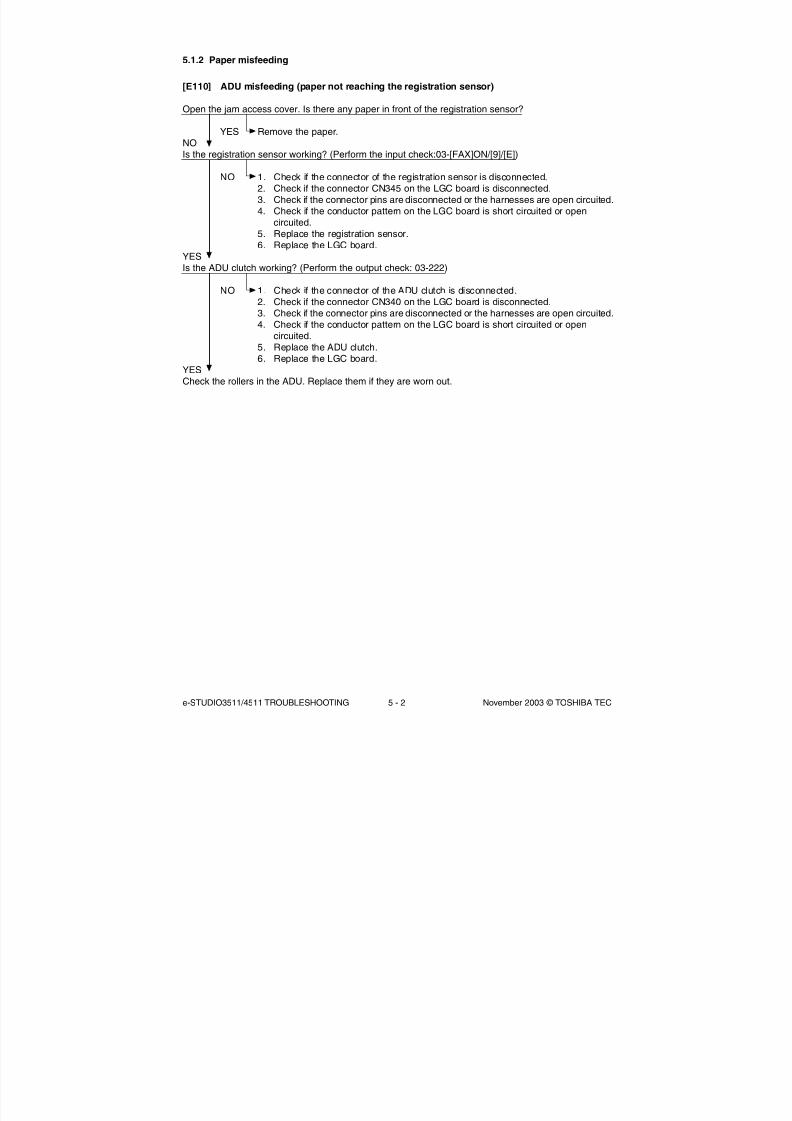
8/2/2019 ES-3511 Service Handbook
http://slidepdf.com/reader/full/es-3511-service-handbook 310/543
e-STUDIO3511/4511 TROUBLESHOOTING 5 - 2 November 2003 © TOSHIBA TEC
5.1.2 Paper misfeeding
[E110] ADU misfeeding (paper not reaching the registration sensor)
Open the jam access cover. Is there any paper in front of the registration sensor?
YES Remove the paper.
NOIs the registration sensor working? (Perform the input check:03-[FAX]ON/[9]/[E])
NO 1. Check if the connector of the registration sensor is disconnected.2. Check if the connector CN345 on the LGC board is disconnected.3. Check if the connector pins are disconnected or the harnesses are open circuited.4. Check if the conductor pattern on the LGC board is short circuited or open
circuited.5. Replace the registration sensor.6. Replace the LGC board.
YESIs the ADU clutch working? (Perform the output check: 03-222)
NO 1. Check if the connector of the ADU clutch is disconnected.2. Check if the connector CN340 on the LGC board is disconnected.3. Check if the connector pins are disconnected or the harnesses are open circuited.4. Check if the conductor pattern on the LGC board is short circuited or open
circuited.5. Replace the ADU clutch.6. Replace the LGC board.
YESCheck the rollers in the ADU. Replace them if they are worn out.

8/2/2019 ES-3511 Service Handbook
http://slidepdf.com/reader/full/es-3511-service-handbook 311/543
November 2003 © TOSHIBA TEC 5 - 3 e-STUDIO3511/4511 TROUBLESHOOTING
[E130] Upper drawer misfeeding (paper not reaching the upper drawer feed sensor)
Open the jam access cover. Is there any paper in front of the upper drawer feed sensor?
YES Remove the paper.NOIs the upper drawer feed sensor working? (Perform the input check: 03-[FAX]ON/[3]/[H])
NO 1. Check if the connector of the upper drawer feed sensor is disconnected.2. Check if the connector CN345 on the LGC board is disconnected.3. Check if the connector pins are disconnected or the harnesses are open circuited.4. Check if the conductor pattern on the LGC board is short circuited or open
circuited.5. Replace the upper drawer feed sensor.6. Replace the LGC board.
YESIs the upper drawer feed clutch working? (Perform the output check: 03-201)
NO 1. Check if the connector of the upper drawer feed clutch is disconnected.2. Check if the connector CN337 on the LGC board is disconnected.3. Check if the connector pins are disconnected or the harnesses are open circuited.4. Check if the conductor pattern on the LGC board is short circuited or open
circuited.5. Replace the upper drawer feed clutch.6. Replace the LGC board.
YESCheck the upper drawer feed roller, separation roller and pickup roller. Replace them if they are wornout.
[E120] Bypass misfeeding (paper not reaching the registration sensor)
Open the jam access cover. Is there any paper in front of the registration sensor?
YES Remove the paper.NOIs the registration sensor working? (Perform the input check: 03-[FAX]ON/[9]/[E])
NO 1. Check if the connector of the registration sensor is disconnected.2. Check if the connector CN345 on the LGC board is disconnected.3. Check if the connector pins are disconnected and the harnesses are open circuited.4. Check if the conductor pattern on the LGC board is short circuited or open
circuited.5. Replace the registration sensor.6. Replace the LGC board.
YESAre the bypass feed clutch and bypass feed sensor working? (Perform the output check: 03-204 and theinput check: 03-[FAX]ON/[9]/[D])
NO 1. Check if the connector of the bypass feed clutch and bypass feed sensor aredisconnected.
2. Check if the connector CN340 on the LGC board is disconnected.3. Check if the connector pins are disconnected and the harnesses are open circuited.4. Check if the conductor pattern on the LGC board is short circuited or open
circuited.5. Replace the bypass feed clutch and bypass feed sensor.6. Replace the LGC board.
YESCheck the bypass transport, feed, separation and pickup rollers. Replace them if they are worn out.

8/2/2019 ES-3511 Service Handbook
http://slidepdf.com/reader/full/es-3511-service-handbook 312/543
e-STUDIO3511/4511 TROUBLESHOOTING 5 - 4 November 2003 © TOSHIBA TEC
[E140] Lower drawer misfeeding (paper not reaching the lower drawer feed sensor)
Open the side cover. Is there any paper in front of the lower drawer feed sensor?
YES Remove the paper.NOIs the lower drawer feed sensor working? (Perform the input check: 03-[FAX]ON/[3]/[G])
NO 1. Check if the connector of the lower drawer feed sensor is disconnected.2. Check if the connector CN345 on the LGC board is disconnected.3. Check if the connector pins are disconnected or the harnesses are open circuited.4. Check if the conductor pattern on the LGC board is short circuited or open
circuited.5. Replace the lower drawer feed sensor.6. Replace the LGC board.
YESIs the lower drawer feed clutch working? (Perform the output check: 03-202)
NO 1. Check if the connector of the lower drawer feed clutch is disconnected.2. Check if the connector CN337 on the LGC board is disconnected.3. Check if the connector pins are disconnected or the harnesses are open circuited.4. Check if the conductor pattern on the LGC board is short circuited or open
circuited.5. Replace the lower drawer feed clutch.6. Replace the LGC board.
YESCheck the lower drawer feed roller, separation roller and pickup roller. Replace them if they are wornout.
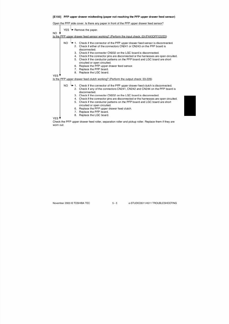
8/2/2019 ES-3511 Service Handbook
http://slidepdf.com/reader/full/es-3511-service-handbook 313/543
November 2003 © TOSHIBA TEC 5 - 5 e-STUDIO3511/4511 TROUBLESHOOTING
[E150] PFP upper drawer misfeeding (paper not reaching the PFP upper drawer feed sensor)
Open the PFP side cover. Is there any paper in front of the PFP upper drawer feed sensor?
YES Remove the paper.NOIs the PFP upper drawer feed sensor working? (Perform the input check: 03-[FAX]OFF/[2]/[D])
NO 1. Check if the connector of the PFP upper drawer feed sensor is disconnected.2. Check if either of the connectors CN241 or CN243 on the PFP board is
disconnected.3. Check if the connector CN332 on the LGC board is disconnected.4. Check if the connector pins are disconnected or the harnesses are open circuited.5. Check if the conductor patterns on the PFP board and LGC board are short
circuited or open circuited.6. Replace the PFP upper drawer feed sensor.7. Replace the PFP board.8. Replace the LGC board.
YESIs the PFP upper drawer feed clutch working? (Perform the output check: 03-226)
NO 1. Check if the connector of the PFP upper drawer feed clutch is disconnected.2. Check if any of the connectors CN241, CN242 and CN244 on the PFP board is
disconnected.3. Check if the connector CN332 on the LGC board is disconnected.4. Check if the connector pins are disconnected or the harnesses are open circuited.5. Check if the conductor patterns on the PFP board and LGC board are short
circuited or open circuited.6. Replace the PFP upper drawer feed clutch.7. Replace the PFP board.8. Replace the LGC board.
YES
Check the PFP upper drawer feed roller, separation roller and pickup roller. Replace them if they areworn out.

8/2/2019 ES-3511 Service Handbook
http://slidepdf.com/reader/full/es-3511-service-handbook 314/543
e-STUDIO3511/4511 TROUBLESHOOTING 5 - 6 November 2003 © TOSHIBA TEC
[E160] PFP lower drawer misfeeding (paper not reaching the PFP lower drawer feed sensor)
Open the PFP side cover. Is there any paper in front of the PFP lower drawer feed sensor?
YES Remove the paper.NOIs the PFP lower drawer feed sensor working? (Perform the input check: 03-[FAX]OFF/[4]/[D])
NO 1. Check if the connector of the PFP lower drawer feed sensor is disconnected.2. Check if either of the connectors CN241 or CN243 on the PFP board is
disconnected.3. Check if the connector CN332 on the LGC board is disconnected.4. Check if the connector pins are disconnected or the harnesses are open circuited.5. Check if the conductor patterns on the PFP board and LGC board are short
circuited or open circuited.6. Replace the PFP lower drawer feed sensor.7. Replace the PFP board.8. Replace the LGC board.
YESIs the PFP lower drawer feed clutch working? (Perform the output check: 03-228)
NO 1. Check if the connector of the PFP lower drawer feed clutch is disconnected.2. Check if any of the connectors CN241, CN242 and CN244 on the PFP board is
disconnected.3. Check if the connector CN332 on the LGC board is disconnected.4. Check if the connector pins are disconnected or the harnesses are open circuited.5. Check if the conductor patterns on the PFP board and LGC board are short
circuited or open circuited.6. Replace the PFP lower drawer feed clutch.7. Replace the PFP board.8. Replace the LGC board.
YES
Check the PFP lower drawer feed roller, separation roller and pickup roller. Replace them if they areworn out.

8/2/2019 ES-3511 Service Handbook
http://slidepdf.com/reader/full/es-3511-service-handbook 315/543
November 2003 © TOSHIBA TEC 5 - 7 e-STUDIO3511/4511 TROUBLESHOOTING
[E190] LCF misfeeding (paper not reaching the LCF feed sensor)
Open the LCF side cover. Is there any paper in front of the LCF feed sensor?
YES Remove the paper.NOIs the LCF feed sensor working? (Perform the input check: 03-[FAX]OFF/[5]/[G])
NO 1. Check if the connector of the LCF feed sensor is disconnected.2. Check if either of the connectors CN100 or CN104 on the LCF board is
disconnected.3. Check if the connector CN332 on the LGC board is disconnected.4. Check if the connector pins are disconnected or the harnesses are open circuited.5. Check if the conductor patterns on the LCF board and LGC board are short
circuited or open circuited.6. Replace the LCF feed sensor.7. Replace the LCF board.8. Replace the LGC board.
YESIs the LCF feed clutch working? (Perform the output check: 03-209)
NO 1. Check if the connector of the LCF feed clutch is disconnected.2. Check if any of the connectors CN100, CN101 and CN103 on the LCF board is
disconnected.3. Check if the connector CN332 on the LGC board is disconnected.4. Check if the connector pins are disconnected or the harnesses are open circuited.5. Check if the conductor patterns on the LCF board and LGC board are short
circuited or open circuited.6. Replace the LCF feed clutch.7. Replace the LCF board.8. Replace the LGC board.
YES
Check the LCF feed roller, separation roller and pickup roller. Replace them if they are worn out.

8/2/2019 ES-3511 Service Handbook
http://slidepdf.com/reader/full/es-3511-service-handbook 316/543
e-STUDIO3511/4511 TROUBLESHOOTING 5 - 8 November 2003 © TOSHIBA TEC
5.1.3 Paper transport jam
[E200] Upper drawer transport jam (not reaching the registration sensor)[E210] Lower drawer transport jam (not reaching the registration sensor)[E300] PFP upper drawer transport jam (not reaching the registration sensor)[E330] PFP lower drawer transport jam (not reaching the registration sensor)[E3C0] LCF transport jam (not reaching the registration sensor)
Open the jam access cover. Is there paper in front of the registration sensor?
YES Remove the paper.NOIs the registration sensor working? (Perform the input check: 03-[FAX]ON/[9]/[E])
NO 1. Check if the connector of the registration sensor is disconnected.2. Check if the connector CN345 on the LGC board is disconnected.3. Check if the connector pins are disconnected or the harnesses are open circuited.4. Check if the conductor pattern on the LGC board is short circuited or open
circuited.
5. Replace the registration sensor.6. Replace the LGC board.
YESAre the upper transport clutches (high/low speed) working? (Perform the output check: 03-439, 440)
NO 1. Check if the connectors of the upper transport clutches (high/low speed) aredisconnected.
2. Check if the connector CN362 on the LGC board is disconnected.3. Check if the connector pins are disconnected or the harnesses are open circuited.4. Check if the conductor pattern on the LGC board is short circuited or open
circuited.5. Replace the upper transport clutches (high/low speed).6. Replace the LGC board.
YES1. Check the condition of the feed roller, separation roller and pickup roller of each paper source, and
replace them if they are worn out.2. Check the transport roller. Replace it if it is worn out.

8/2/2019 ES-3511 Service Handbook
http://slidepdf.com/reader/full/es-3511-service-handbook 317/543
November 2003 © TOSHIBA TEC 5 - 9 e-STUDIO3511/4511 TROUBLESHOOTING
[E220] Lower drawer transport jam (not reaching the upper drawer feed sensor)[E310] PFP upper drawer transport jam (not reaching the upper drawer feed sensor)[E340] PFP lower drawer transport jam (not reaching the upper drawer feed sensor)[E3D0] LCF transport jam (not reaching the upper drawer feed sensor)
Open the jam access cover. Is there paper in front of the upper drawer feed sensor?
YES Remove the paper.NOIs the upper drawer feed sensor working? (Perform the input check: 03-[FAX]ON/[3]/[H])
NO 1. Check if the connector of the upper drawer feed sensor is disconnected.2. Check if the connector CN345 on the LGC board is disconnected.3. Check if the connector pins are disconnected or the harnesses are open circuited.4. Check if the conductor pattern on the LGC board is short circuited or open
circuited.5. Replace the upper drawer feed sensor.6. Replace the LGC board.
YESAre the lower transport clutches (high/low speed) working? (Perform the output check: 03-203, 205)
NO 1. Check if the connectors of the lower transport clutches (high/low speed) aredisconnected.
2. Check if the connector CN337 on the LGC board is disconnected.3. Check if the connector pins are disconnected or the harnesses are open circuited.4. Check if the conductor pattern on the LGC board is short circuited or open
circuited.5. Replace the lower transport clutches (high/low speed).6. Replace the LGC board.
YES1. Check the condition of the feed roller, separation roller and pickup roller of each paper source, and
replace them if they are worn out.
2. Check the transport roller. Replace it if it is worn out.

8/2/2019 ES-3511 Service Handbook
http://slidepdf.com/reader/full/es-3511-service-handbook 318/543
e-STUDIO3511/4511 TROUBLESHOOTING 5 - 10 November 2003 © TOSHIBA TEC
[E320] PFP upper drawer transport jam (not reaching the lower drawer feed sensor)[E350] PFP lower drawer transport jam (not reaching the lower drawer feed sensor)[E3E0] LCF transport jam (not reaching the lower drawer feed sensor)
Open the side cover. Is there paper in front of the lower drawer feed sensor?
YES Remove the paper.
NOIs the lower drawer feed sensor working? (Perform the input check: 03-[FAX]ON/[3]/[G])
NO 1. Check if the connector of the lower drawer feed sensor is disconnected.2. Check if the connector CN345 on the LGC board is disconnected.3. Check if the connector pins are disconnected or the harnesses are open circuited.4. Check if the conductor pattern on the LGC board is short circuited or open
circuited.5. Replace the lower drawer feed sensor.6. Replace the LGC board.
YESAre the lower transport clutches working? (Perform the output check: 03-203, 205)
NO 1. Check if the connectors of the lower transport clutches (high/low speed) aredisconnected.
2. Check if the connector CN337 on the LGC board is disconnected.3. Check if the connector pins are disconnected or the harnesses are open circuited.4. Check if the conductor pattern on the LGC board is short circuited or open
circuited.5. Replace the lower transport clutches (high/low speed).6. Replace the LGC board.
YESWhen the paper fed from the PFP:Is the PFP transport clutch working? (Perform the output check: 03-225)
NO 1. Check if the connector of the PFP transport clutch is disconnected.2. Check if any of the connectors CN241, CN242 and CN244 on the PFP board is
disconnected.3. Check if the connector CN332 on the LGC board is disconnected.4. Check if the connector pins are disconnected or the harnesses are open circuited.5. Check if the conductor patterns on the PFP board and LGC board are short
circuited or open circuited.6. Replace the PFP transport clutch.7. Replace the PFP board.8. Replace the LGC board.
YES1. Check the condition of the feed roller, separation roller and pickup roller of each paper source, and
replace them if they are worn out.2. Check the transport roller. Replace it if it is worn out.

8/2/2019 ES-3511 Service Handbook
http://slidepdf.com/reader/full/es-3511-service-handbook 319/543
November 2003 © TOSHIBA TEC 5 - 11 e-STUDIO3511/4511 TROUBLESHOOTING
[E360] PFP lower drawer transport jam (not reaching the PFP upper drawer feed sensor)
Open the PFP side cover. Is there any paper in front of the PFP upper drawer feed sensor?
YES Remove the paper.NOIs the PFP upper feed sensor working?
(Perform the input check: 03-[FAX]OFF/[2]/[D])
NO 1. Check if the connector of the PFP upper drawer feed sensor is disconnected.2. Check if either of the connectors CN241 or CN243 on the PFP board is
disconnected.3. Check if the connector CN332 on the LGC board is disconnected.4. Check if the connector pins are disconnected or the harnesses are open circuited.5. Check if the conductor patterns on the PFP board and LGC board are short
circuited or open circuited.6. Replace the PFP upper drawer feed sensor.7. Replace the PFP board.8. Replace the LGC board.
YESIs the PFP transport clutch working? (Perform the output check: 03-225)
NO 1. Check if the connector of the PFP transport clutch is disconnected.2. Check if any of the connectors CN241, CN242 and CN244 on the PFP board is
disconnected.3. Check if the connector CN332 on the LGC board is disconnected.4. Check if the connector pins are disconnected or the harnesses are open circuited.5. Check if the conductor patterns on the PFP board and LGC board are short
circuited or open circuited.6. Replace the PFP transport clutch.7. Replace the PFP board.8. Replace the LGC board.
YES1. Check the condition of the feed roller, separation roller and pickup roller of each paper source, and
replace them if they are worn out.2. Check the PFP transport roller. Replace it if it is worn out.

8/2/2019 ES-3511 Service Handbook
http://slidepdf.com/reader/full/es-3511-service-handbook 320/543
e-STUDIO3511/4511 TROUBLESHOOTING 5 - 12 November 2003 © TOSHIBA TEC
[E510] ADU transport stop jam
Open the ADU. Is there any paper in front of the ADU exit sensor?
YES Remove the paper.NOIs the ADU exit sensor working? (Perform the input check: 03-[FAX]OFF/[8]/[H])
NO 1. Check if the connector of the ADU exit sensor is disconnected.2. Check if either of the connectors CN211 or CN213 on the ADU board is
disconnected.3. Check if the connector CN340 on the LGC board is disconnected.4. Check if the connector pins are disconnected or the harnesses are open circuited.5. Check if the conductor patterns on the ADU board and LGC board are short
circuited or open circuited.6. Replace the ADU exit sensor.7. Replace the ADU board.8. Replace the LGC board.
YESIs the ADU clutch working? (Perform the output check: 03-222)
NO 1. Check if the connector of the ADU clutch is disconnected.2. Check if the connector CN340 on the LGC board is disconnected.3. Check if the connector pins are disconnected or the harnesses are open circuited.4. Check if the conductor pattern on the LGC board is short circuited or open
circuited.5. Replace the ADU clutch.6. Replace the LGC board.
YESCheck the rollers in the ADU. Replace them if they are worn out.

8/2/2019 ES-3511 Service Handbook
http://slidepdf.com/reader/full/es-3511-service-handbook 321/543
November 2003 © TOSHIBA TEC 5 - 13 e-STUDIO3511/4511 TROUBLESHOOTING
[E520] Stop jam in the ADU
Open the ADU. Is there any paper in front of the ADU entrance sensor?
YES Remove the paper.NOIs the ADU entrance sensor working? (Perform the input check: 03-[FAX]OFF/[8]/[G])
NO 1. Check if the connector of the ADU entrance sensor is disconnected.2. Check if either of the connectors CN211 or CN214 on the ADU board is
disconnected.3. Check if the connector CN340 on the LGC board is disconnected.4. Check if the connector pins are disconnected or the harnesses are open circuited.5. Check if the conductor patterns on the ADU board and LGC board are short
circuited or open circuited.6. Replace the ADU entrance sensor.7. Replace the ADU board.8. Replace the LGC board.
YESIs the exit motor (rotating in reverse) working? (Perform the output check: 03-121/171)
NO 1. Check if the connector of the exit motor is disconnected.2. Check if the connectors CN437 and J434 on the DRV board is disconnected.3. Check if the connector CN360 on the LGC board is disconnected.4. Check if the connector pins are disconnected or the harnesses are open circuited.5. Check if the conductor patterns on the DRV board and LGC board are short
circuited or open circuited.6. Replace the exit motor.7. Replace the DRV board.8. Replace the LGC board.
YESIs the ADU motor working? (Perform the output check: 03-110/160)
NO 1. Check if the connector of the ADU motor is disconnected.2. Check if any of the connectors CN211, CN212 and CN215 on the ADU board is
disconnected.3. Check if the connector CN340 on the LGC board is disconnected.4. Check if the connector pins are disconnected or the harnesses are open circuited.5. Check if the conductor patterns on the ADU board and LGC board are short
circuited or open circuited.6. Replace the ADU board.7. Replace the LGC board.
YESCheck the rollers in the ADU and the exit roller of the equipment. Replace them if they are worn out.

8/2/2019 ES-3511 Service Handbook
http://slidepdf.com/reader/full/es-3511-service-handbook 322/543
e-STUDIO3511/4511 TROUBLESHOOTING 5 - 14 November 2003 © TOSHIBA TEC
[EB50] Paper remaining on the transport path due to multiple feeding
When the paper is fed from any of the upper drawer, bypass feed unit or ADU:
Open the jam access cover. Is there any paper in front of the registration sensor?
YES Remove the paper.
NOWhen the paper is fed from the upper drawer:Is the upper drawer feed sensor working? (Perform the input check: 03-[FAX]ON/[3]/[H])
NO 1. Check if the connector of the upper drawer feed sensor is disconnected.2. Check if the connector CN345 on the LGC board is disconnected.3. Check if the connector pins are disconnected or the harnesses are open circuited.4. Check if the conductor pattern on the LGC board is short circuited or open
circuited.5. Replace the upper drawer feed sensor.6. Replace the LGC board.
YES
When the paper is fed from the bypass feed unit:Is the bypass feed sensor working? (Perform the input check: 03-[FAX]ON/[9]/[D])
NO 1. Check if the connector of the bypass feed sensor is disconnected.2. Check if the connector CN340 on the LGC board is disconnected.3. Check if the connector pins are disconnected or the harnesses are open circuited.4. Check if the conductor pattern on the LGC board is short circuited or open
circuited.5. Replace the bypass feed sensor.6. Replace the LGC board.
YESWhen the paper is fed from the ADU:Is the ADU exit sensor working? (Perform the input check: 03-[FAX]OFF/[8]/[H])
NO 1. Check if the connector of the ADU exit sensor is disconnected.2. Check if either of the connectors CN211 or CN213 on the ADU board is
disconnected.3. Check if the connector CN340 on the LGC board is disconnected.4. Check if the connector pins are disconnected or the harnesses are open circuited.5. Check if the conductor patterns on the ADU board and LGC board are short
circuited or open circuited.6. Replace the ADU exit sensor.7. Replace the ADU board.8. Replace the LGC board.
YES
Is the registration sensor working? (Perform the input check: 03-[FAX]ON/[9]/[E])
NO 1. Check if the connector of the registration sensor is disconnected.2. Check if the connector CN345 on the LGC board is disconnected.3. Check if the connector pins are disconnected or the harnesses are open circuited.4. Check if the conductor pattern on the LGC board is short circuited or open
circuited.5. Replace the registration sensor.6. Replace the LGC board.
YESCheck the rollers. Replace them if they are worn out.

8/2/2019 ES-3511 Service Handbook
http://slidepdf.com/reader/full/es-3511-service-handbook 323/543
November 2003 © TOSHIBA TEC 5 - 15 e-STUDIO3511/4511 TROUBLESHOOTING
[EB60] Paper remaining on the transport path due to multiple feeding
Open the jam access cover. Is there any paper in front of the registration sensor?
YES Remove the paper.NOIs the registration sensor working? (Perform the input check: 03-[FAX]ON/[9]/[E])
NO 1. Check if the connector of the registration sensor is disconnected.2. Check if the connector CN345 on the LGC board is disconnected.3. Check if the connector pins are disconnected or the harnesses are open circuited.4. Check if the conductor pattern on the LGC board is short circuited or open
circuited.5. Replace the registration sensor.6. Replace the LGC board.
YESCheck the rollers. Replace them if they are worn out.
When the paper is fed from any of the lower drawer, PFP or LCF:
Open the jam access cover. Is there any paper in front of the upper drawer feed sensor?
YES Remove the paper.NOAre the upper/lower drawer feed sensors working?
(Perform the input check: 03-[FAX]ON/[3]/[H], /[3]/[G])
NO 1. Check if the connectors of the upper/lower drawer feed sensors are disconnected.2. Check if the connector CN345 on the LGC board is disconnected.3. Check if the connector pins are disconnected or the harnesses are open circuited.4. Check if the conductor pattern on the LGC board is short circuited or open
circuited.5. Replace the upper/lower drawer feed sensors.6. Replace the LGC board.
YESCheck the rollers. Replace them if they are worn out.

8/2/2019 ES-3511 Service Handbook
http://slidepdf.com/reader/full/es-3511-service-handbook 324/543
e-STUDIO3511/4511 TROUBLESHOOTING 5 - 16 November 2003 © TOSHIBA TEC
5.1.4 Other paper jam
[E011] Paper jam caused by clinging to the transfer belt
Open the jam access cover. Is the paper clinging to the transfer belt?Is the paper clinging to the transfer belt entering under the receiving tray?
YES 1. Remove the paper.2. Use the paper within the specification if the thin paper being used is out of
specification.Notes:
1. If the paper is remaining under the receiving tray, a scratched image occurs atprinting in the color modes.
2. The paper smaller than B5 may easily enter under the receiving tray.NOIs there any stain or poor cleaning area on the transfer belt?
YES 1. Clean the transfer belt.2. Check the installation and operation of the transfer belt cleaner.
NOIs the paper clinging detection sensor working? (Perform the input check: 03-[FAX]OFF/[9]/[H])
NO 1. Is the detection area of the paper clinging detection sensor dirty?2. Check if the connector of the paper clinging detection sensor and joint
connectors (3 pcs.) are disconnected.3. Check if the connector CN331 of the LGC board is disconnected.4. Check if the harness is open circuited or the connector pin is disconnected.5. Replace the paper clinging detection sensor.6. Replace the LGC board.
YESReplace the LGC board.

8/2/2019 ES-3511 Service Handbook
http://slidepdf.com/reader/full/es-3511-service-handbook 325/543
November 2003 © TOSHIBA TEC 5 - 17 e-STUDIO3511/4511 TROUBLESHOOTING
[E030] Power-ON jam
Open the cover of the unit/area whose picture is flashing on the control panel. Is there any paper on thetransport path? (Refer to the following table)
YES Remove the paper.NO
Is the sensor in the jamming area working? (Perform the input check: Refer to the following table.)
NO 1. Check if the connector of the sensor is disconnected.2. Check if any of the connectors on the LGC board is disconnected.3. Check if the connector pins are disconnected or the harnesses are open circuited.4. Check if the conductor pattern on the LGC board is short circuited or open
circuited.5. Replace the sensor.6. Replace the LGC board.
YESReplace the LGC board.
Relation between the jamming area and the corresponding sensors/covers(If a jam is occurring in the ADU, LCF or PFP, check the board in each unit.)
[E090] Paper jam by HDD abnormality
(1) Check if the error is cleared by turning the power OFF and then back ON.
(2) Check if the connectors of the HDD are disconnected.
(3) Check if the connector pins are disconnected or the harnesses are open circuited.
(4) Replace the HDD.
(5) Replace the SYS board.
Jamming area
Registration area
Exit area
ADU
Feeding area (equipment)
Bypass unit
LCF
PFP
Bridge unit
Test Mode/Input check
03-[FAX]ON/[9]/[E]
03-[FAX]ON/[3]/[H]
03-[FAX]OFF/[7]/[H]
03-[FAX]OFF/[8]/[H]
03-[FAX]OFF/[8]/[G]
03-[FAX]ON/[3]/[G]
03-[FAX]ON/[9]/[D]
03-[FAX]OFF/[5]/[G]
03-[FAX]OFF/[2]/[D]
03-[FAX]OFF/[4]/[D]03-[FAX]ON/[0]/[C]
03-[FAX]ON/[0]/[A]
Cover
Jam access cover
Fuser cover
ADU
Side cover
Bypass unit
LCF side cover
PFP side cover
Bridge unit
Sensor
Registration sensor
Upper drawer feed sensor
Exit sensor
ADU entrance sensor
ADU exit sensor
Lower drawer feed sensor
Bypass feed sensor
LCF feed sensor
PFP upper drawer feed sensor
PFP lower drawer feed sensorBridge unit transport sensor-1
Bridge unit transport sensor-2

8/2/2019 ES-3511 Service Handbook
http://slidepdf.com/reader/full/es-3511-service-handbook 326/543
e-STUDIO3511/4511 TROUBLESHOOTING 5 - 18 November 2003 © TOSHIBA TEC
[E550] Paper remaining on the transport path
Open the cover of the unit/area whose picture is flashing on the control panel. Is there any paper on thetransport path?
YES Remove the paper.NO
Is the sensor in the jamming area working? (Perform the input check: Refer to the following table)
NO 1. Check if the connector of the sensor is disconnected.2. Check if any of the connectors on the LGC board is disconnected.3. Check if the connector pins are disconnected or the harnesses are open circuited.4. Check if the conductor pattern on the LGC board is short circuited or open
circuited.5. Replace the sensor.6. Replace the LGC board.
YESReplace the LGC board.
Relation between the jamming area and the corresponding sensors/covers(If a jam is occurring in the ADU, LCF or PFP, check the board in each unit.)
Jamming area
Registration area
Exit area
ADU
Bypass unit
Feeding area (equipment)
LCF
PFP
Bridge unit
Finisher
Test Mode/Input check
03-[FAX]ON/[9]/[E]
03-[FAX]ON/[3]/[H]
03-[FAX]OFF/[7]/[H]
03-[FAX]OFF/[8]/[H]
03-[FAX]OFF/[8]/[G]
03-[FAX]ON/[9]/[D]
03-[FAX]ON/[3]/[G]
03-[FAX]OFF/[5]/[G]
03-[FAX]OFF/[2]/[D]
03-[FAX]OFF/[4]/[D]03-[FAX]ON/[0]/[C]
03-[FAX]ON/[0]/[A]
-
Cover
Jam access cover
Fuser cover
ADU
Bypass unit
Side cover
LCF side cover
PFP side cover
Bridge unit
Finisher door
Sensor
Registration sensor
Upper drawer feed sensor
Exit sensor
ADU entrance sensor
ADU exit sensor
Bypass feed sensor
Lower drawer feed sensor
LCF feed sensor
PFP upper drawer feed sensor
PFP lower drawer feed sensorBridge unit transport sensor-1
Bridge unit transport sensor-2
Sensors in the finisher

8/2/2019 ES-3511 Service Handbook
http://slidepdf.com/reader/full/es-3511-service-handbook 327/543
November 2003 © TOSHIBA TEC 5 - 19 e-STUDIO3511/4511 TROUBLESHOOTING
5.1.5 Cover open jam
[E400] Jam access cover open
Is the jam access cover open?
YES Remove paper if there is any, then shut the cover.
NOIs the voltage of 24V being supplied from the power supply unit?(Perform the input check: 03-[FAX] ON/[1]/[H])
NO 1. Check if the connector for 24V power supply is disconnected.2. Check if the connector CN350 on the LGC board is disconnected.3. Check if the connector pins are disconnected or the harnesses are open circuited.4. Check if the conductor pattern on the LGC board is short circuited or open
circuited.5. Replace the LGC board.
YESReplace the LGC board.
[E410] Front cover open jam
Is the front cover open?
YES Shut the cover.NOIs the voltage of 24V being supplied from the power supply unit?(Perform the input check: 03-[FAX] ON/[1]/[H])
NO 1. Check if the connector for 24V power supply is disconnected.2. Check if the connector CN350 on the LGC board is disconnected.
3. Check if the connector pins are disconnected or the harnesses are open circuited.4. Check if the conductor pattern on the LGC board is short circuited or opencircuited.
5. Replace the LGC board.YESIs the front cover opening/closing switch working?(Perform the input check: 03-[FAX]OFF/[7]/[F]
NO 1. Check if the connector of the front cover opening/closing switch is disconnected.2. Check if the connector CN345 on the LGC board is disconnected.3. Check if the connector pins are disconnected or the harnesses are open circuited.4. Check if the conductor pattern on the LGC board is short circuited or open
circuited.5. Replace the front cover opening/closing switch.6. Replace the LGC board.
YESReplace the LGC board.
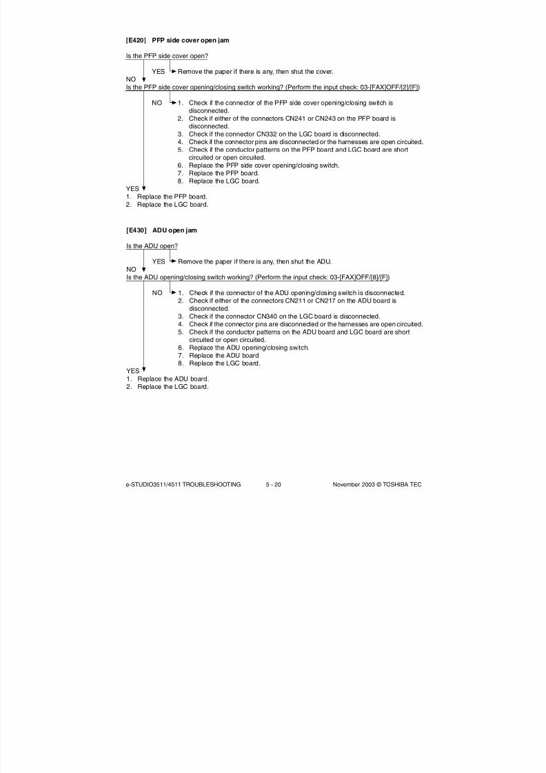
8/2/2019 ES-3511 Service Handbook
http://slidepdf.com/reader/full/es-3511-service-handbook 328/543
e-STUDIO3511/4511 TROUBLESHOOTING 5 - 20 November 2003 © TOSHIBA TEC
[E420] PFP side cover open jam
Is the PFP side cover open?
YES Remove the paper if there is any, then shut the cover.NOIs the PFP side cover opening/closing switch working? (Perform the input check: 03-[FAX]OFF/[2]/[F])
NO 1. Check if the connector of the PFP side cover opening/closing switch isdisconnected.
2. Check if either of the connectors CN241 or CN243 on the PFP board isdisconnected.
3. Check if the connector CN332 on the LGC board is disconnected.4. Check if the connector pins are disconnected or the harnesses are open circuited.5. Check if the conductor patterns on the PFP board and LGC board are short
circuited or open circuited.6. Replace the PFP side cover opening/closing switch.7. Replace the PFP board.8. Replace the LGC board.
YES1. Replace the PFP board.2. Replace the LGC board.
[E430] ADU open jam
Is the ADU open?
YES Remove the paper if there is any, then shut the ADU.NOIs the ADU opening/closing switch working? (Perform the input check: 03-[FAX]OFF/[8]/[F])
NO 1. Check if the connector of the ADU opening/closing switch is disconnected.2. Check if either of the connectors CN211 or CN217 on the ADU board is
disconnected.3. Check if the connector CN340 on the LGC board is disconnected.4. Check if the connector pins are disconnected or the harnesses are open circuited.5. Check if the conductor patterns on the ADU board and LGC board are short
circuited or open circuited.6. Replace the ADU opening/closing switch.7. Replace the ADU board.8. Replace the LGC board.
YES1. Replace the ADU board.
2. Replace the LGC board.

8/2/2019 ES-3511 Service Handbook
http://slidepdf.com/reader/full/es-3511-service-handbook 329/543
November 2003 © TOSHIBA TEC 5 - 21 e-STUDIO3511/4511 TROUBLESHOOTING
[E440] Side cover open jam
Is the side cover open?
YES Remove the paper if there is any, then shut the cover.NOIs the side door switch working?
(Perform the input check: 03-[FAX]OFF/[7]/[E])
NO 1. Check if the connector of the side door switch is disconnected.2. Check if the connector CN345 on the LGC board is disconnected.3. Check if the connector pins are disconnected or the harnesses are open circuited.4. Check if the conductor pattern on the LGC board is short circuited or open
circuited.5. Replace the side door switch.6. Replace the LGC board.
YESReplace the LGC board.
[E450] LCF side cover open jam
Is the LCF side cover open?
YES Remove the paper if there is any, then shut the cover.NOIs the LCF side cover opening/closing switch working?(Perform the input check: 03-[FAX]OFF/[5]/[D])
NO 1. Check if the connector of the LCF side cover opening/closing switch isdisconnected.
2. Check if either of the connectors CN100 or CN106 on the LCF board is
disconnected.3. Check if the connector CN332 on the LGC board is disconnected.4. Check if the connector pins are disconnected or the harnesses are open circuited.5. Check if the conductor patterns on the LCF board and LGC board are short
circuited or open circuited.6. Replace the LCF side cover opening/closing switch.7. Replace the LCF board.8. Replace the LGC board.
YES1. Replace the LCF board.2. Replace the LGC board.

8/2/2019 ES-3511 Service Handbook
http://slidepdf.com/reader/full/es-3511-service-handbook 330/543
e-STUDIO3511/4511 TROUBLESHOOTING 5 - 22 November 2003 © TOSHIBA TEC
[E480] Bridge unit open jam
Is the Bridge unit open?
YES Remove the paper if there is any, then close the unit.NOIs the bridge unit cover opening/closing detection switch working?
(Perform the input check: 03-[FAX]ON/[0]/[B])
NO 1. Check if the connector of the bridge unit cover opening/closing detection switchis disconnected.
2. Check if the connector CN351 on the LGC board is disconnected.3. Check if the connector pins are disconnected or the harnesses are open circuited.4. Check if the conductor pattern on the LGC board is short circuited or open
circuited.5. Replace the bridge unit cover opening/closing detection switch.6. Replace the LGC board.
YESReplace the LGC board.

8/2/2019 ES-3511 Service Handbook
http://slidepdf.com/reader/full/es-3511-service-handbook 331/543
November 2003 © TOSHIBA TEC 5 - 23 e-STUDIO3511/4511 TROUBLESHOOTING
5.1.6 RADF jam
Note:
When performing the RADF related troubleshooting, be sure to perform “Automatic adjustment of RADF sensor and
EEPROM initialization (05-356)” and then "RADF original guide width adjustment (05-367, 368)" at Adjustment
Mode whenever the RADF board, original length sensor, read sensor or reverse sensor has been replaced.
[E711] Jam not reaching the original length sensor[E712] Jam not reaching the registration sensor[E713] Stop jam at the original length sensor
Are the pickup roller, feed roller and separation roller stained or worn out?
YES Clean the rollers or replace them.NOIs the original excessively curled or folded?
YES Flatten and set it again.NOAre the original length sensor and registration sensor working?(Perform the input check: 03-[FAX]ON/[8]/[E], [7]/[H])
NO 1. Check if the connectors of the original length sensor and registration sensor aredisconnected.
2. Check if the connector CN3 on the RADF board is disconnected.3. Check if the connector pins are disconnected or the harnesses are open circuited.4. Check if the conductor pattern on the RADF board is short circuited or open
circuited.5. Replace the original length sensor and registration sensor.6. Replace the RADF board.
YESReplace the RADF board.
[E714] Feed signal reception jam
Is the empty sensor working? (Perform the input check: 03-[FAX]ON/[7]/[B])
NO 1. Check if the lever of empty sensor is working normally.2. Check if the connector of the empty sensor is disconnected.3. Check if the connector CN5 on the RADF board is disconnected.4. Check if the connector pins are disconnected or the harnesses are open circuited.
5. Check if the conductor pattern on the RADF board is short circuited or opencircuited.
6. Replace the empty sensor.7. Replace the RADF board.
YESReplace the RADF board.

8/2/2019 ES-3511 Service Handbook
http://slidepdf.com/reader/full/es-3511-service-handbook 332/543
e-STUDIO3511/4511 TROUBLESHOOTING 5 - 24 November 2003 © TOSHIBA TEC
[E721] Jam not reaching the read sensor
Are the registration roller and read roller stained?
YES Clean the rollers.NOIs the read sensor working? (Perform the input check: 03-[FAX]ON/[7]/[G])
NO 1. Check if the connector of the read sensor are disconnected.2. Check if the connector CN6 on the RADF board is disconnected.3. Check if the connector pins are disconnected or the harnesses are open circuited.4. Check if the conductor pattern on the RADF board is short circuited or open
circuited.5. Replace the read sensor.6. Replace the RADF board.
YESReplace the RADF board.
[E722] Jam not reaching the exit sensor (during scanning)[E723] Jam not reaching the reverse sensor (during scanning)
Is the read roller stained?
YES Clean the roller.NOAre the exit sensor and reverse sensor working? (Perform the input check: 03-[FAX]ON/[7]/[E], [7]/[F])
NO 1. Check if the connectors of the exit sensor and reverse sensor are disconnected.2. Check if the connector CN4 on the RADF board is disconnected.3. Check if the connector pins are disconnected or the harnesses are open circuited.4. Check if the conductor pattern on the RADF board is short circuited or open
circuited.5. Replace the exit sensor and reverse sensor.6. Replace the RADF board.
YESReplace the RADF board.
[E724] Stop jam at the registration sensor
Is the registration roller stained?
YES Clean the roller.
NOIs the registration sensor working? (Perform the input check: 03-[FAX]ON/[7]/[H])
NO 1. Check if the connector of the registration sensor is disconnected.2. Check if the connector CN3 on the RADF board is disconnected.3. Check if the connector pins are disconnected or the harnesses are open circuited.4. Check if the conductor pattern on the RADF board is short circuited or open
circuited.5. Replace the registration sensor.6. Replace the RADF board.
YESReplace the RADF board.

8/2/2019 ES-3511 Service Handbook
http://slidepdf.com/reader/full/es-3511-service-handbook 333/543
November 2003 © TOSHIBA TEC 5 - 25 e-STUDIO3511/4511 TROUBLESHOOTING
[E725] Stop jam at the read sensor
Is the read roller stained?
YES Clean the roller.NOIs the read sensor working? (Perform the input check: 03-[FAX]ON/[7]/[G])
NO 1. Check if the connector of the read sensor is disconnected.2. Check if the connector CN6 on the RADF board is disconnected.3. Check if the connector pins are disconnected or the harnesses are open circuited.4. Check if the conductor pattern on the RADF board is short circuited or open
circuited.5. Replace the read sensor.6. Replace the RADF board.
YESReplace the RADF board.
[E726] Transport/exit signal reception jam
1. If the original is remained in the RADF, remove it.
2. If any paper is remained in the copier, remove it.
3. Turn the power OFF and then back ON. If the jam still occurs, lead the following procedure.
4. Check the connection between the RADF board and SLG board, and the connection between the
RADF board and switching power supply.
- Are the connection of the connectors and joint connectors normal?
- Are the connector pins disconnected or are the harnesses open circuited?
5. Check if the 24V and 5V outputs of the switching power supply are normal.
6. Check if the conductor pattern on the RADF board is short circuited or open circuited.
7. Replace the RADF board.
8. Check if the conductor pattern on the SLG board is short circuited or open circuited.
9. Replace the SLG board.
[E731] Stop jam at the exit sensor
Is the exit roller stained?
YES Clean the roller.NO
Is the exit sensor working? (Perform the input check: 03-[FAX]ON/[7]/[E])
NO 1. Check if the connector of the exit sensor is disconnected.2. Check if the connector CN4 on the RADF board is disconnected.3. Check if the connector pins are disconnected or the harnesses are open circuited.4. Check if the conductor pattern on the RADF board is short circuited or open
circuited.5. Replace the exit sensor.6. Replace the RADF board.
YESReplace the RADF board.

8/2/2019 ES-3511 Service Handbook
http://slidepdf.com/reader/full/es-3511-service-handbook 334/543
e-STUDIO3511/4511 TROUBLESHOOTING 5 - 26 November 2003 © TOSHIBA TEC
[E741] Stop jam at the reverse sensor
Are the read roller and reverse roller stained?
YES Clean the rollers.NOIs the reverse sensor working? (Perform the input check: 03-[FAX]ON/[7]/[F])
NO 1. Check if the connector of the reverse sensor is disconnected.2. Check if the connector CN4 on the RADF board is disconnected.3. Check if the connector pins are disconnected or the harnesses are open circuited.4. Check if the conductor pattern on the RADF board is short circuited or open
circuited.5. Replace the reverse sensor.6. Replace the RADF board.
YESReplace the RADF board.
[E742] Jam not reaching the reverse sensor (feeding in reverse)
Is the reverse roller stained?
YES Clean the roller.NOIs the reverse sensor working? (Perform the input check: 03-[FAX]ON/[7]/[F])
NO 1. Check if the connector of the reverse sensor is disconnected.2. Check if the connector CN4 on the RADF board is disconnected.3. Check if the connector pins are disconnected or the harnesses are open circuited.4. Check if the conductor pattern on the RADF board is short circuited or open
circuited.
5. Replace the reverse sensor.6. Replace the RADF board.
YESReplace the RADF board.
[E743] Jam not reaching the exit sensor (feeding in reverse)
Are the reverse roller and read roller stained?
YES Clean the rollers.NO
Is the exit sensor working? (Perform the input check: 03-[FAX]ON/[7]/[E])
NO 1. Check if the connector of the exit sensor is disconnected.2. Check if the connector CN4 on the RADF board is disconnected.3. Check if the connector pins are disconnected or the harnesses are open circuited.4. Check if the conductor pattern on the RADF board is short circuited or open
circuited.5. Replace the exit sensor.6. Replace the RADF board.
YESReplace the RADF board.

8/2/2019 ES-3511 Service Handbook
http://slidepdf.com/reader/full/es-3511-service-handbook 335/543
November 2003 © TOSHIBA TEC 5 - 27 e-STUDIO3511/4511 TROUBLESHOOTING
[E860] Jam access cover open
Is the jam access cover opened?
YES Remove the original, if any, and close the jam access cover.NOIs the jam access cover switch working? (Perform the input check: 03-[FAX]ON/[7]/[C])
NO 1. Check if the connector of the jam access cover switch is disconnected.2. Check if the connector CN8 on the RADF board is disconnected.3. Check if the connector pins are disconnected or the harnesses are open circuited.4. Check if the conductor pattern on the RADF board is short circuited or open
circuited.5. Replace the jam access cover switch.6. Replace the RADF board.
YESReplace the RADF board.
[E870] RADF open jam
Is the RADF opened?
YES Remove the original, if any, and close the RADF.NOIs the RADF opening/closing sensor adjusted within the specified range?
NO Adjust the RADF opening/closing sensor.YESIs the RADF opening/closing sensor working? (Perform the input check: 03-[FAX]ON/[7]/[D])
NO 1. Check if the connector of the RADF opening/closing sensor is disconnected.
2. Check if the connector CN6 on the RADF board is disconnected.3. Check if the connector pins are disconnected or the harnesses are open circuited.4. Check if the conductor pattern on the RADF board is short circuited or open
circuited.5. Replace the RADF opening/closing sensor.6. Replace the RADF board.
YESReplace the RADF board.

8/2/2019 ES-3511 Service Handbook
http://slidepdf.com/reader/full/es-3511-service-handbook 336/543
e-STUDIO3511/4511 TROUBLESHOOTING 5 - 28 November 2003 © TOSHIBA TEC
5.1.7 Finisher jam
(1) Jam in bridge unit
[E910] Paper not reaching the bridge unit transport sensor-1[E920] Paper stopping at the bridge unit transport sensor-1
[E930] Paper not reaching the bridge unit transport sensor-2[E940] Paper stopping at the bridge unit transport sensor-2
Is there any paper remaining inside the bridge unit?
YES Remove the paper.NOAre the bridge unit transport sensors-1 and -2 working?(Perform the input check:03-[FAX]ON/[0]/[C], /[0]/[A])
NO 1. Check if the connectors of the bridge unit transport sensors-1 and -2 aredisconnected.
2. Check if the connector J510 of the bridge unit is disconnected.3. Check if the connector CN351 on the LGC board is disconnected.4. Check if the connector pins are disconnected or the harnesses are open circuited.5. Check if the conductor pattern on the LGC board is short circuited or open
circuited.6. Replace the bridge unit transport sensors-1 and -2.7. Replace the LGC board.
YESIs the bridge unit gate solenoid working? (Perform the output check: 03-232)
NO 1. Check if the connector J510 of the bridge unit is disconnected.2. Check if the connector CN351 on the LGC board is disconnected.3. Check if the connector pins are disconnected or the harnesses are open circuited.
4. Replace the bridge unit gate solenoid.5. Replace the LGC board.
YESDoes the transport roller of the bridge unit work when the main motor is rotated?(Perform the output check: 03-101/151)
NO Check the drive system of the equipment and bridge unit.YESCheck if the rollers in the bridge unit are worn out.

8/2/2019 ES-3511 Service Handbook
http://slidepdf.com/reader/full/es-3511-service-handbook 337/543
November 2003 © TOSHIBA TEC 5 - 29 e-STUDIO3511/4511 TROUBLESHOOTING
(2) Paper jam in finisher section
[EA10] Paper transport delay jam
MJ-1022
Is there any paper remaining on the transport path in the finisher or equipment?
YES Remove the paper.NOIs the connector J10 on the finisher controller PC board disconnected?Is the harness connecting the finisher controller PC board and inlet sensor (S2) open circuited?
YES Connect the connector securely. Replace the harness.NOIs the inlet sensor working normally? (Check the movement of the actuator.)
NO 1. Connect the connector of the inlet sensor securely.2. Attach the actuator securely if its shaft is out of place.
3. Replace the inlet sensor.YESReplace the finisher controller PC board.
MJ-1023/1024
Is there any paper remaining on the transport path in the finisher or equipment?
YES Remove the paper.NOIs the connector J708 on the finisher controller PC board disconnected?Is the harness connecting the finisher controller PC board and inlet sensor (PI33) open circuited?
YES Connect the connector securely. Replace the harness.NOIs the inlet sensor working properly? (Check the movement of the actuator.)
NO 1. Connect the connector of the inlet sensor securely.2. Attach the actuator securely if its shaft is out of place.3. Replace the inlet sensor.
YESReplace the finisher controller PC board.

8/2/2019 ES-3511 Service Handbook
http://slidepdf.com/reader/full/es-3511-service-handbook 338/543
e-STUDIO3511/4511 TROUBLESHOOTING 5 - 30 November 2003 © TOSHIBA TEC
[EA20] Paper transport stop jam
MJ-1022
Is there any paper remaining on the transport path in the finisher or equipment?
YES Remove the paper.
NOIs the connector J10 on the finisher controller PC board disconnected?Is the harness connecting the finisher controller PC board and inlet sensor (S2) open circuited?
YES Connect the connector securely. Replace the harness.NOIs the inlet sensor working properly? (Check the movement of the actuator.)
NO 1. Connect the connector of the inlet sensor securely.2. Attach the actuator securely if its shaft is out of place.3. Replace the inlet sensor.
YESReplace the finisher controller PC board.
MJ-1023/1024
Is there any paper remaining on the transport path in the finisher or equipment?
YES Remove the paper.NOIs any of the connectors (J707, J708 and J722B) on the finisher controller PC board disconnected?Is the harness between the finisher controller PC board and each sensor (the inlet sensor [PI33], thetransport path sensor [PI34], the processing tray sensor [PI38]) open circuited?
YES Connect the connectors securely. Replace the harnesses.NOIs each of the sensors (the inlet sensor, the transport path sensor and the processing tray sensor)working properly? (Check the movement of the actuator.)
NO 1. Connect the connectors of the sensors securely.2. Attach the actuators securely if their shafts are out of place.3. Replace the sensors.
YESReplace the finisher controller PC board.

8/2/2019 ES-3511 Service Handbook
http://slidepdf.com/reader/full/es-3511-service-handbook 339/543
November 2003 © TOSHIBA TEC 5 - 31 e-STUDIO3511/4511 TROUBLESHOOTING
[EA30] Power-ON jam
MJ-1022
Is there any paper remaining on the transport path in the finisher?
YES Remove the paper.
NOIs the connector J10 on the finisher controller PC board disconnected?Is the harness connecting the finisher controller PC board and inlet sensor (S2) open circuited?
YES Connect the connector securely. Replace the harness.NOIs the inlet sensor working properly? (Check the movement of the actuator.)
NO 1. Connect the connector of the inlet sensor securely.2. Attach the actuator securely if its shaft is out of place.3. Replace the inlet sensor.
YESReplace the finisher controller PC board.
MJ-1023/1024
Is there any paper remaining on the transport path in the finisher?
YES Remove the paper.NOIs any of the connectors J707, J708 and J722B on the finisher controller PC board disconnected?Is the harness between the finisher controller PC board and each sensor (the inlet sensor [PI33], thetransport path sensor [PI34], the processing tray sensor [PI38], open circuited?
YES Connect the connectors securely. Replace the harnesses.NOIs each of the sensors (the inlet sensor, the transport path sensor and the processing tray sensor)working properly?(Check the movement of the actuator.)
NO 1. Connect the connectors of the sensors securely.2. Attach the actuators securely if their shafts are out of place.3. Replace the sensors.
YESReplace the finisher controller PC board.

8/2/2019 ES-3511 Service Handbook
http://slidepdf.com/reader/full/es-3511-service-handbook 340/543
e-STUDIO3511/4511 TROUBLESHOOTING 5 - 32 November 2003 © TOSHIBA TEC
[EA40] Door open jam
MJ-1022
Is there any paper remaining on the transport path in the finisher or equipment?
YES Remove the paper.
NOIs the finisher connected with the equipment?
NO Connect the finisher with the equipment.YESIs the connector J11 on the finisher controller PC board disconnected?Is the harness connecting the finisher controller PC board and joint sensor (S4) open circuited?
YES Connect the connector securely. Replace the harness.NOIs the joint sensor working properly?
NO 1. Connect the connector of the joint sensor securely.2. Replace the joint sensor.
YESReplace the finisher controller PC board.

8/2/2019 ES-3511 Service Handbook
http://slidepdf.com/reader/full/es-3511-service-handbook 341/543
November 2003 © TOSHIBA TEC 5 - 33 e-STUDIO3511/4511 TROUBLESHOOTING
MJ-1023/1024
Is there any paper remaining on the transport path in the finisher or equipment?
YES Remove the paper.NOIs either of the covers upper or front of the finisher closed?
NO Close the door.YESIs any connectors J707 and J708 on the finisher controller PC board disconnected?Is the harness connecting the finisher controller PC board and upper/front cover opening sensors(PI31 and PI32) open circuited?
YES Connect the connector securely. Replace the harness.NOIs the upper/front cover opening sensor working properly?
NO 1. Connect the connector of the upper/front cover opening sensor securely.2. Replace the upper/front cover opening sensor.
YESIs the connector J719 on the finisher controller PC board disconnected?Is the harness connecting the finisher controller PC board and front cover switch (MS31) open circuited?
YES Connect the connector securely. Replace the harness.NOIs the front cover switch working properly?
NO 1. Connect the connector of the front cover switch securely.2. Replace the front cover switch.
Is the connector J5 on the punch controller PC board disconnected?
Is the harness connecting the punch controller PC board and upper door switch (MSW61) open circuited?Is the harness connecting the punch controller PC board and front door switch (MSW62) open circuited?
YES Connect the connector securely. Replace the harness.NOAre the upper and front door switches working properly?
NO 1. Connect the connectors of the upper and front door switches securely.2. Replace the upper/front door switches.
YESReplace the finisher controller PC board.

8/2/2019 ES-3511 Service Handbook
http://slidepdf.com/reader/full/es-3511-service-handbook 342/543
e-STUDIO3511/4511 TROUBLESHOOTING 5 - 34 November 2003 © TOSHIBA TEC
[EA50] Stapling jam
MJ-1022
Is there any paper remaining on the transport path in the finisher or equipment or on the stapling tray?
YES Remove the paper.
NOIs the jam cleared by taking off the staple cartridge from the finisher and removing the staple sheet slidfrom the staple case?
YES End.NOIs the connector J8 on the finisher controller PC board disconnected?Is the harness connecting the finisher controller PC board and stapling home position sensor (S17)open circuited?
YES Connect the connector securely. Replace the harness.NOIs the stapling home position sensor working properly?
NO 1. Connect the connector of the stapling home position sensor securely.2. Replace the stapling home position sensor.
YESReplace the finisher controller PC board.
MJ-1023/1024
Is there any paper remaining on the transport path in the finisher or equipment or on the stapling tray?
YES Remove the paper.
NOIs the jam cleared by taking off the staple cartridge from the finisher and removing the staple sheet slidfrom the staple case?
YES End.NOIs the connector J721B on the finisher controller PC board disconnected?Is the harness connecting the finisher controller PC board and staple home position sensor (PI40)open circuited?
YES Connect the connector securely. Replace the harness.NO
Is the staple home position sensor working properly?
NO 1. Connect the connector of the staple home position sensor securely.2. Replace the staple home position sensor.
YESReplace the finisher controller PC board.

8/2/2019 ES-3511 Service Handbook
http://slidepdf.com/reader/full/es-3511-service-handbook 343/543
November 2003 © TOSHIBA TEC 5 - 35 e-STUDIO3511/4511 TROUBLESHOOTING
[EA60] Early arrival jam
MJ-1022
Is there any paper remaining on the transport path in the finisher or equipment?
YES Remove the paper.
NOIs the connector J10 on the finisher controller PC board disconnected?Is the harness connecting the finisher controller PC board and inlet sensor (S2) open circuited?
YES Connect the connector securely. Replace the harness.NOIs the inlet sensor working properly? (Check the movement of the actuator.)
NO 1. Connect the connector of the inlet sensor securely.2. Attach the actuator securely if its shaft is out of place.3. Replace the inlet sensor.
YESReplace the finisher controller PC board.
MJ-1023/1024
Is there any paper remaining on the transport path in the finisher or equipment?
YES Remove the paper.NOIs the connector J708 on the finisher controller PC board disconnected?Is the harness connecting the finisher controller PC board and inlet sensor (PI33) open circuited?
YES Connect the connector securely. Replace the harness.
NOIs the inlet sensor working properly? (Check the movement of the actuator.)
NO 1. Connect the connector of the inlet sensor securely.2. Attach the actuator securely if its shaft is out of place.3. Replace the inlet sensor.
YESReplace the finisher controller PC board.

8/2/2019 ES-3511 Service Handbook
http://slidepdf.com/reader/full/es-3511-service-handbook 344/543
e-STUDIO3511/4511 TROUBLESHOOTING 5 - 36 November 2003 © TOSHIBA TEC
[EA70] Stack delivery jam
MJ-1022
Is there any paper remaining on the transport path in the finisher or equipment?
YES Remove the paper.
NOIs the connector J9 on the finisher controller PC board disconnected?Is the harness connecting the finisher controller PC board and stack delivery lever home position sensor(S8) open circuited?
YES Connect the connector securely. Replace the harness.NOIs the stack delivery lever home position sensor working properly?
NO 1. Connect the connector of the stack delivery lever home position sensorsecurely.
2. Replace the stack delivery lever home position sensor.
YESReplace the finisher controller PC board.
[EAF0] Stack return jam
MJ-1022
Is there any paper remaining on the transport path in the finisher or equipment?
YES Remove the paper.NOIs the connector J10 on the finisher controller PC board disconnected?
Is the harness connecting the finisher controller PC board and returning roller home position sensor (S3)open circuited?
YES Connect the connector securely. Replace the harness.NOIs the returning roller home position sensor working properly?
NO 1. Connect the connector of the returning roller home position sensor securely.2. Replace the returning roller home position sensor.
YESReplace the finisher controller PC board.

8/2/2019 ES-3511 Service Handbook
http://slidepdf.com/reader/full/es-3511-service-handbook 345/543
November 2003 © TOSHIBA TEC 5 - 37 e-STUDIO3511/4511 TROUBLESHOOTING
(3) Paper jam in saddle stitcher section
[EA80] Stapling jam
MJ-1024
Is there any paper remaining on the transport path or the stapling tray in the finisher, saddle stitcher
section or equipment?
YES Remove the paper.NOIs the jam cleared by taking off the staple cartridge from the finisher and removing the staples stuck inthe stapling unit?
YES End.NOIs the connector J8 on the saddle stitcher controller PC board disconnected?Is the harness connecting the saddle stitcher controller PC board and stitcher home position switch(rear: SW5, front: SW7 open circuited?
YES Connect the connector securely. Replace the harness.NOAre the stitcher home position switches working properly?
NO 1. Connect the connectors of the stitcher home position switches securely.2. Replace the stitcher home position switches.
YESReplace the saddle stitcher controller PC board.
[EA90] Door open jam
MJ-1024
Is there any paper remaining on the transport path in the finisher, saddle stitcher section or equipment?
YES Remove the paper.NOIs the saddle stitcher door closed?
NO Close the door.YESIs either of the connectors J10 or J11 on saddle stitcher controller PC board disconnected?Are the harnesses between the saddle stitcher controller PC board and cover opening sensors (delivery
cover sensor [PI3], inlet cover sensor [PI9]) open circuited?
YES Connect the connector securely. Replace the harness.NOIs each of the sensors (delivery cover sensor, inlet cover sensor) working properly?
NO 1. Connect the connectors of the each sensor securely.2. Replace the sensors.
YESReplace the finisher controller PC board.

8/2/2019 ES-3511 Service Handbook
http://slidepdf.com/reader/full/es-3511-service-handbook 346/543
e-STUDIO3511/4511 TROUBLESHOOTING 5 - 38 November 2003 © TOSHIBA TEC
[EAA0] Power-ON jam
MJ-1024
Is there any paper remaining on the transport path in the finisher or saddle stitcher section?
YES Remove the paper.
NOIs any of the connectors J9, J10 and J13 on the saddle stitcher controller PC board disconnected?Is the harness between the saddle stitcher controller PC board and each sensor (No.1 paper sensor[PI18], No.2 paper sensor [PI19], No.3 paper sensor [PI20], the vertical path paper sensor [PI17]and the delivery sensor[PI11]) open circuited?
YES Connect the connectors securely. Replace the harnesses.NOIs each of the sensors (No.1 paper sensor, No.2 paper sensor, No.3 paper sensor, the vertical pathpaper sensor, and the delivery sensor) working properly?(Check the movement of the actuator.)
NO 1. Connect the connectors of the sensors securely.2. Attach the actuators securely if their shafts are out of place.3. Replace the sensors.
YESReplace the saddle stitcher controller PC board.
[EAB0] Paper transport stop jam
MJ-1024
Is there any paper remaining on the transport path in the finisher, saddle stitcher section or equipment?
YES Remove the paper.NOIs the connector J708 on finisher controller PC board disconnected?Is the harness between the finisher controller PC board and inlet sensor [PI33] open circuited?Is either of the connectors J9 or J10 on the saddle stitcher controller PC board disconnected?Is the harness between the saddle stitcher controller PC board and each sensor (No.1 paper sensor[PI18], No.2 paper sensor [PI19], No.3 paper sensor [PI20] and the delivery sensor [PI11])open circuited?
YES Connect the connectors securely. Replace the harnesses.NOIs each of the sensors (the inlet sensor, No.1 paper sensor, No.2 paper sensor, No.3 paper sensor and
the delivery sensor) working properly?(Check the movement of the actuator.)
NO 1. Connect the connectors of the sensors securely.2. Attach the actuators securely if their shafts are out of place.3. Replace the sensors.
YESReplace the saddle stitcher controller PC board.

8/2/2019 ES-3511 Service Handbook
http://slidepdf.com/reader/full/es-3511-service-handbook 347/543
November 2003 © TOSHIBA TEC 5 - 39 e-STUDIO3511/4511 TROUBLESHOOTING
[EAC0] Transport delay jam
MJ-1024
Is there any paper remaining on the transport path in the finisher, saddle stitcher section or equipment?
YES Remove the paper.
NOIs the connector J708 on the finisher controller PC board disconnected?Is the harness connecting the finisher controller PC board and inlet sensor (PI33) open circuited?
YES Connect the connector securely. Replace the harness.NOIs the inlet sensor working properly? (Check the movement of the actuator.)
NO 1. Connect the connector of the sensor securely.2. Attach the actuator securely if its shaft is out of place.3. Replace the sensor.
YESReplace the finisher controller PC board.
(4) Paper jam in puncher unit
[E9F0] Punching jam
MJ-1023/1024
Is there any paper remaining on the transport path in the finisher or equipment?
YES Remove the paper.
NOIs the connector J605A on the punch controller PC board disconnected?Is the harness connecting the punch controller PC board and punch home position sensor (PI63)open circuited?
YES Connect the connector securely. Replace the harness.NOIs the punch home position sensor working properly?
NO 1. Connect the connector of the punch home position sensor securely.2. Replace the punch home position sensor.
YES
Replace the punch controller PC board.
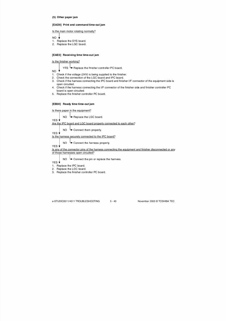
8/2/2019 ES-3511 Service Handbook
http://slidepdf.com/reader/full/es-3511-service-handbook 348/543
e-STUDIO3511/4511 TROUBLESHOOTING 5 - 40 November 2003 © TOSHIBA TEC
[EB30] Ready time time-out jam
Is there paper in the equipment?
NO Replace the LGC board.
YESAre the IPC board and LGC board properly connected to each other?
NO Connect them properly.YESIs the harness securely connected to the IPC board?
NO Connect the harness properly.YESIs any of the connector pins of the harness connecting the equipment and finisher disconnected or anyof those harnesses open circuited?
NO Connect the pin or replace the harness.YES1. Replace the IPC board.2. Replace the LGC board.3. Replace the finisher controller PC board.
(5) Other paper jam
[EAD0] Print end command time-out jam
Is the main motor rotating normally?
NO
1. Replace the SYS board.2. Replace the LGC board.
[EAE0] Receiving time time-out jam
Is the finisher working?
YES Replace the finisher controller PC board.NO1. Check if the voltage (24V) is being supplied to the finisher.2. Check the connection of the LGC board and IPC board.
3. Check if the harness connecting the IPC board and finisher I/F connector of the equipment side isopen circuited.
4. Check if the harness connecting the I/F connector of the finisher side and finisher controller PCboard is open circuited.
5. Replace the finisher controller PC board.

8/2/2019 ES-3511 Service Handbook
http://slidepdf.com/reader/full/es-3511-service-handbook 349/543
November 2003 © TOSHIBA TEC 5 - 41 e-STUDIO3511/4511 TROUBLESHOOTING
5.1.8 Drive system related service call
[C010] Main motor abnormality
Is the main motor working? (Perform the output check: 03-101/151)
NO 1. Check if the connector J581 of the main motor is disconnected.
2. Check if the connector CN347 on the LGC board is disconnected.3. Check if the connector pins are disconnected or the harnesses are open
circuited.4. Check if the conductor patterns on the main motor board and LGC board are
short circuited or open circuited.5. Replace the main motor.6. Replace the LGC board.
YES1. Check if the PLL lock signal CN347-8 pin output from the LGC board is always level “L”.2. Check if the voltage supplied to the ASIC input terminal IC38-152 pin is always “L”.3. Replace the LGC board.
[C020] Developer motor abnormality
Is the developer unit motor working? (Perform the output check: 03-112/162)
NO 1. Check if the connector J578 of the developer motor is disconnected.2. Check if the connector CN348 on the LGC board is disconnected.3. Check if the connector pins are disconnected or the harnesses are open
circuited.4. Check if the conductor patterns on the developer motor board and LGC board
are short circuited or open circuited.5. Replace the developer motor.6. Replace the LGC board.
YES1. Check if the PLL lock signal CN348-B6 pin output from the LGC board is always level “L”.2. Check if the voltage supplied to the ASIC input terminal IC38-150 pin is always “L”.3. Replace the LGC board.
[C030] Transport motor abnormality
Is the transport motor working? (Perform the output check: 03-123/173)
NO 1. Check if the connector J582 of the transport motor is disconnected.2. Check if the connector CN348 on the LGC board is disconnected.3. Check if the connector pins are disconnected or the harnesses are open
circuited.4. Check if the conductor patterns on the transport motor board and LGC board
are short circuited or open circuited.5. Replace the transport motor.6. Replace the LGC board.
YES1. Check if the PLL lock signal CN348-A7 pin output from the LGC board is always level “L”.2. Check if the voltage supplied to the ASIC input terminal IC38-149 pin is always “L”.3. Replace the LGC board.

8/2/2019 ES-3511 Service Handbook
http://slidepdf.com/reader/full/es-3511-service-handbook 350/543
e-STUDIO3511/4511 TROUBLESHOOTING 5 - 42 November 2003 © TOSHIBA TEC
5.1.9 Paper feeding system related service call
[C040] PFP motor abnormality
Is the PFP motor working? (Perform the output check: 03-109/159)
NO 1. Check if the signal line connector CN503 of the PFP motor is disconnected.
2. Check if the power line connector CN502 of the PFP motor is disconnected.3. Check if the connector CN246 on the PFP board is disconnected.4. Check if the signal line connector CN241 on the PFP board is disconnected.5. Check if the power line connector CN242 on the PFP board is disconnected.6. Check if the connector CN332 on the LGC board is disconnected.7. Check if the connector pins are disconnected or the harnesses are open circuited.8. Check if the conductor patterns on the PFP motor board, PFP board and LGC
board are short circuited or open circuited.9. Replace the PFP motor.10. Replace the PFP board.11. Replace the LGC board.
YES
Is the LED on the PFP motor board lit without flashing?
NO 1. Check if the connector pins are disconnected or the harnesses are open circuited.2. Check if the conductor patterns on the PFP motor board, PFP board and LGC
board are short circuited or open circuited.3. Replace the PFP motor.4. Replace the PFP board.5. Replace the LGC board.
YES1. Check if the PLL lock signal CN246-8 pin output from the PFP board is always “L” level.2. Check if the voltage supplied to the microcomputer input terminal IC5-17 pin is always “L” level.3. Replace the PFP board.4. Replace the LGC board.

8/2/2019 ES-3511 Service Handbook
http://slidepdf.com/reader/full/es-3511-service-handbook 351/543
November 2003 © TOSHIBA TEC 5 - 43 e-STUDIO3511/4511 TROUBLESHOOTING
[C130] Upper drawer tray abnormality[C140] Lower drawer tray abnormality
Does the tray go up? (Perform the output check: 03-242, 243)
NO 1. Check if the connector of the tray-up motor is disconnected.2. Check if the connector CN337 on the LGC board is disconnected.3. Check if the connector pins are disconnected or the harnesses are open circuited.4. Check if the conductor pattern on the LGC board is short circuited or open
circuited.5. Replace the LGC board.
YESIs the tray-up sensor working?(Perform the input check: 03-[FAX]OFF/[6]/[H], /[6]/[G])
NO 1. Check if the connector of the sensor is disconnected.2. Check if the connector CN337 on the LGC board is disconnected.3. Check if the slit reaches the sensor.4. Check if the connector pins are disconnected or the harnesses are open circuited.5. Check if the conductor pattern on the LGC board is short circuited or open
circuited.
6. Replace the LGC board.YES1. Check if the conductor pattern on the LGC board is short circuited or open circuited.2. Replace the LGC board.
[C150] PFP upper drawer tray abnormality[C160] PFP lower drawer tray abnormality
Does the tray go up? (Perform the output check: 03-278, 280)
NO 1. Check if the connector of the tray-up motor is disconnected.2. Check if any of the connectors CN241, CN242 and CN244 on the PFP board is
disconnected.3. Check if the connector CN332 on the LGC board is disconnected.4. Check if the connector pins are disconnected or the harnesses are open circuited.5. Check if the conductor patterns on the PFP board and LGC board are short
circuited or open circuited.6. Replace the PFP board.7. Replace the LGC board.
YESIs the tray-up sensor working?(Perform the input check: 03-[FAX]OFF/[2]/[H], /[4]/[H])
NO 1. Check if the connector of the sensor is disconnected.2. Check if any of the connectors CN241, CN247 and CN248 on the PFP board is
disconnected.3. Check if the connector CN332 on the LGC board is disconnected.4. Check if the slit reaches the sensor.5. Check if the connector pins are disconnected or the harnesses are open circuited.6. Check if the conductor patterns on the PFP board and LGC board are short
circuited or open circuited.7. Replace the PFP board.8. Replace the LGC board.
YES1. Check if the conductor pattern on the LGC board is short circuited or open circuited.2. Replace the LGC board.

8/2/2019 ES-3511 Service Handbook
http://slidepdf.com/reader/full/es-3511-service-handbook 352/543
e-STUDIO3511/4511 TROUBLESHOOTING 5 - 44 November 2003 © TOSHIBA TEC
[C180] LCF tray motor abnormality
Does the tray move? (Perform the output check: 03-271)
NO 1. Check if the connector of the LCF tray motor is disconnected.2. Check if any of the connectors CN100, CN101 and CN103 on the LCF board is
disconnected.
3. Check if the connector CN332 on the LGC board is disconnected.4. Check if the connector pins are disconnected or the harnesses are open circuited.5. Check if the conductor patterns on the LCF board and LGC board are short
circuited or open circuited.6. Replace the LCF board.7. Replace the LGC board.
YESAre the LCF tray-up sensor and LCF tray bottom sensor working?(Perform the input check: 03-[FAX]OFF/[5]/[F], /[3]/[A])
NO 1. Check if the connectors of the sensors are disconnected.2. Check if any of the connectors CN100, CN104 and CN105 on the LCF board is
disconnected.3. Check if the connector CN332 on the LGC board is disconnected.4. Check if the slit reaches the sensors.5. Check if the connector pins are disconnected or the harnesses are open circuited.6. Check if the conductor patterns on the LCF board and LGC board are short
circuited or open circuited.7. Replace the LCF board.8. Replace the LGC board.
YES1. Check if the conductor pattern on the LGC board is short circuited or open circuited.2. Replace the LGC board.

8/2/2019 ES-3511 Service Handbook
http://slidepdf.com/reader/full/es-3511-service-handbook 353/543
November 2003 © TOSHIBA TEC 5 - 45 e-STUDIO3511/4511 TROUBLESHOOTING
[C1A0] LCF end fence motor abnormality
Is the LCF end fence motor working? (Perform the output check: 03-207)
NO 1. Check if the connector of the LCF end fence motor is disconnected.2. Check if any of the connectors CN100, CN101 and CN103 on the LCF board is
disconnected.
3. Check if the connector CN332 on the LGC board is disconnected.4. Check if the connector pins are disconnected or the harnesses are open circuited.5. Check if the conductor patterns on the LCF board and LGC board are short
circuited or open circuited.6. Replace the LCF board.7. Replace the LGC board.
YESAre the LCF end fence home/stop position sensors working?(Perform the input check: 03-[FAX]OFF/[5]/[A], /[5]/[B])
NO 1. Check if the connectors of the sensors are disconnected.2. Check if either of the connectors CN100 or CN107 on the LCF board is
disconnected.3. Check if the connector CN332 on the LGC board is disconnected.4. Check if the slit reaches the sensors.5. Check if the connector pins are disconnected or the harnesses are open circuited.6. Check if the conductor patterns on the LCF board and LGC board are short
circuited or open circuited.7. Replace the LCF board.8. Replace the LGC board.
YES1. Check if the conductor pattern on the LGC board is short circuited or open circuited.2. Replace the LGC board.
[C1B0] LCF transport motor abnormality
Is the LCF transport motor working? (Perform the output check: 03-122/172)
NO 1. Check if the connector CN112 of the LCF transport motor is disconnected.2. Check if the connector CN102 on the LCF board is disconnected.3. Check if the signal line connector CN100 on the LCF board is disconnected.4. Check if the power line connector CN101 on the LCF board is disconnected.5. Check if the connector CN332 on the LGC board is disconnected.6. Check if the connector pins are disconnected or the harnesses are open circuited.7. Check if the conductor patterns on the LCF transport motor board, LCF board
and LGC board are short circuited or open circuited.8. Replace the LCF transport motor.
9. Replace the LCF board.10. Replace the LGC board.
YES1. Check if the connector pins are disconnected or the harnesses are open circuited.2. Check if the conductor patterns on the LCF transport motor board, LCF board and LGC board are
short circuited or open circuited.3. Check if the PLL lock signal CN102-3 pin output from the LCF board is always “L” level.4. Check if the voltage supplied to the microcomputer input terminal IC103-17 pin is always “L” level.5. Replace the LCF transport motor.6. Replace the LCF board.7. Replace the LGC board.

8/2/2019 ES-3511 Service Handbook
http://slidepdf.com/reader/full/es-3511-service-handbook 354/543
e-STUDIO3511/4511 TROUBLESHOOTING 5 - 46 November 2003 © TOSHIBA TEC
5.1.10 Scanning system related service call
[C260] Peak detection error
Does the exposure lamp light? (Perform the output check: 03-267)
YES 1. Check if the connectors on the CCD and SLG boards are disconnected.
2. Check if the shading correction plate is dirty.3. Check if the conductor pattern on the CCD board is short circuited or open
circuited.4. Check if the conductor pattern on the SLG board is short circuited or open
circuited.5. Replace the lens unit.6. Replace the SLG board.
NO1. Check if the connectors of the exposure lamp and inverter are disconnected.2. Check the SLG board if the connector pin CN21 is disconnected or the harness is short circuited
or open circuited.3. Check if the conductor pattern on the SLG board is short circuited or open circuited.
4. Replace the SLG board.5. Replace the inverter.6. Replace the exposure lamp.
[C270] Carriage home position sensor not going OFF within a specified time[C280] Carriage home position sensor not going ON within a specified time
Remove the original glass and move the carriages to the paper feeding side. Turn ON the power andcheck the following items.
[C270] Are the carriages slightly moved to the feeding direction?/Are the carriages staying at a positionother than home position?
YES Check if the circuits of the SLG and SDV boards are abnormal.NO1. Check if the connector pin is disconnected or the harness is short circuited or open circuited.2. Check if the conductor pattern on the SDV board is short circuited or open circuited.3. Check if the conductor pattern on the SLG board is short circuited or open circuited.4. Replace the SDV board.5. Replace the SLG board.
[C280] Do the carriages make a big noise after they arrive at the home position?
YES The carriage home position sensor is not turned ON.
1. Check if the connector of the sensor is disconnected.2. Check if the circuits of the SDV and SLG boards are abnormal.NOThe carriages are stopped at the home position and do not move.1. Check if the connector pins are disconnected or the harnesses are short circuited or open
circuited.2. Check if the conductor pattern on the SDV board is short circuited or open circuited.3. Check if the conductor pattern on the SLG board is short circuited or open circuited.4. Replace the SDV board.5. Replace the SLG board.

8/2/2019 ES-3511 Service Handbook
http://slidepdf.com/reader/full/es-3511-service-handbook 355/543
November 2003 © TOSHIBA TEC 5 - 47 e-STUDIO3511/4511 TROUBLESHOOTING
5.1.11 Fuser unit related service call
Be sure to turn OFF the power and unplug the power cable beforehand when checking the IH control
circuit and IH coil.
The fuser unit itself or the part of the unit remains heated and the capacitors are still charged after a
while the power cable is unplugged. So make sure the unit is cooled down enough before checking.
[C410] Thermistor or heater abnormality at power ON
1. Check the thermistors(1) Check if the connectors are disconnected.(2) Check if the main, sub and front edge thermistors are in contact with the surface of the fuser belt
properly?(3) Check if the harnesses of the main, sub and front edge thermistors are open circuited.
2. Check the IH control board and IH coil(1) Check if the IH coil is broken.(2) Check if the connector of the IH coil is disconnected.
(3) Check if the thermostats are blown.(4) Check if the connectors on the IH control board are disconnected (AC input connectors CN450,
451 and LGC I/F connectors CN455, 456).(5) Check if the IH control board or the switching power supply unit is abnormal.
3. Check the LGC board(1) Check if the connector CN358 is disconnected.(2) Check if the conductor pattern on the LGC board is short circuited or open circuited.(3) Replace the LGC board.
4. Clear the status counterAfter repairing the matter which caused the error [C410], perform the following:
(1) Turn ON the power while [0] and [8] are pressed simultaneously.(2) Key in “400”, then press the [START] button.(3) Change the current status counter value “1” or “2” to “0”, then press the [ENTER] button or
[INTERRUPT] button (to cancel [C410]).(4) Turn the power OFF and then back ON. Make sure that the equipment enters the normal ready state.
[C430] Thermistor abnormality after abnormality judgment[C440] Heater abnormality after abnormality judgment
1.2.3. Check the thermistors, IH control board, IH coil and LGC boardCheck the above components following the procedure 1, 2 and 3 for [C410].
4. Clear the status counterChange the current status counter value (08-400) “4” to “0” for [C430] and “5”, “7” or “9” to “0” for[C440], taking the same procedure as that for [C410].
* The status counter value is as follows in the following cases. Change them to "0" respectively.• The error occurred during warming-up : "4" or "5"• The error occurred after the equipment has become ready: "7"• The temperature detected by the main thermistor is 230°C or higher: "9"• The temperature detected by the sub thermistor is 230°C or higher: "9"
CAUTION:CAUTION:

8/2/2019 ES-3511 Service Handbook
http://slidepdf.com/reader/full/es-3511-service-handbook 356/543
e-STUDIO3511/4511 TROUBLESHOOTING 5 - 48 November 2003 © TOSHIBA TEC
[C450] Thermistor abnormality during printing
1. Check the front edge thermistor(1) Check if the connector is disconnected.(2) Check if the front edge thermistor is in contact with the surface of the fuser belt properly.(3) Check if the harness of the front edge thermistor is open circuited.
2. Check the LGC board(1) Check if the connector CN358 is disconnected.(2) Check if the conductor pattern on the board is short circuited or open circuited.(3) Replace the LGC board.
3. Clear the status counterChange the current status counter value (08-400) “6” to “0”.
[C470] IH initialization or IH power voltage abnormality
1. Check the AC input voltageCheck if the AC input voltage is within the specified range.(especially when the heater becomes ON after the power is turned ON [the equipment is warming up])
2. Check the thermostatsCheck if the thermostats are blown.
3. Check the IH control board(1) Check if the AC input connectors CN450, 451 on the IH control board or the LGC I/F connectors
CN455, 456 are disconnected?(2) Check if the fuse on the IH control board has blown.(3) Replace the IH control board.
4. Check the LGC board
(1) Check if the connector CN358 is disconnected.(2) Check if the conductor pattern on the board is short circuited or open circuited.(3) Replace the LGC board.
5. Clear the status counterChange the values “10”, “11”, “14” or “17” of the status counter (08-400) to “0”.
* The status counter value is as follows in the following cases. Change them to "0" respectively.• The error occurred immediately after the power was turned ON: "10"• The error occurred before the temperature of the fuser roller reaches 40°C: "11"• The error occurred before the equipment has become ready: "14"• The error occurred when the equipment is in the ready state: "17"

8/2/2019 ES-3511 Service Handbook
http://slidepdf.com/reader/full/es-3511-service-handbook 357/543
November 2003 © TOSHIBA TEC 5 - 49 e-STUDIO3511/4511 TROUBLESHOOTING
[C480] Overheating of IGBT
1. Check the operation of the IH control board cooling fanCheck if the IH control board cooling fan is rotating normally. (Is the connector securely connected?)
2. Check the IH board(1) Check if the IGBT or IGBT radiation plate is normal. (Is the radiation plate securely attached?)
(2) Check if the conductor pattern on the board is short circuited or open circuited.(3) Replace the IH board.
3. Clear the status counterChange the values “12”, “15” or “18” of the status counter (08-400) to “0”.
* The status counter value is as follows in the following cases. Change them to "0" respectively.• The error occurred before the temperature of the fuser roller reaches 40°C: "12"• The error occurred before the equipment has become ready: "15"• The error occurred when the equipment is in the ready state: "18"
(When the only one side of IH coil is energized continuously for 15 seconds)
[C490] IH control circuit or IH coil abnormality
1. Check the IH board(1) Check if the conductor pattern on the board is short circuited or open circuited.(2) Replace the IH board.
2. Check the IH coil(1) Check if the coil is broken or short out.(2) Replace the IH coil.
3. Clear the status counterChange the values “13”, “16” or “19” of the status counter (08-400) to “0”.
* The status counter value is as follows in the following cases. Change them to "0" respectively.• The error occurred before the temperature of the fuser roller reaches 40°C: "13"• The error occurred before the equipment has become ready: "16"• The error occurred when the equipment is in the ready state: "19"
When the problem is solved, [C470], [C480] and [C490] can be cleared by turning OFF andON the main switch so the status counter does not have to be changed to "0".The value of the status counter remains the same until the next service call overwrites the value.

8/2/2019 ES-3511 Service Handbook
http://slidepdf.com/reader/full/es-3511-service-handbook 358/543
e-STUDIO3511/4511 TROUBLESHOOTING 5 - 50 November 2003 © TOSHIBA TEC
5.1.12 Communication related service call
[C550] RADF I/F error
(1) Check if the harness connecting the RADF board and SLG board is disconnected or opencircuited.
(2) Check if the conductor pattern on the RADF board is short circuited or open circuited.
(3) Check if the conductor pattern on the SLG board is short circuited or open circuited.(4) Replace the RADF board.(5) Replace the SLG board.
[C570] Communication error between Engine-CPU and IPC board
(1) Check if the LGC board and IPC board are connected properly.(2) Check if the conductor pattern on the IPC board is short circuited or open circuited.(3) Check if the conductor pattern on the LGC board is short circuited or open circuited.(4) Replace the IPC board.
(5) Replace the LGC board.
[C580] Communication error between IPC board and finisher
(1) Check if the specified finisher is attached.(2) Check if the harness connecting the IPC board and the finisher controller PC board is
disconnected or open circuited.(3) Check if the conductor pattern on the IPC board is short circuited or open circuited.(4) Check if the conductor pattern on the finisher controller PC board is short circuited or open
circuited.(5) Replace the IPC board.(6) Replace the finisher controller PC board.
[F070] Communication error between System-CPU and Engine-CPU
(1) Check if the harness connecting the SYS board and LGC board is disconnected or open circuited.(2) Check the version of the system ROM on the SYS board.(3) Check the version of the engine ROM version on the LGC board.(4) Replace the SYS board.(5) Replace the LGC board.
[F110] Communication error between System-CPU and Scanner-CPU[F111] Scanner response abnormality
(1) Check if the harness connecting the SYS board and SLG board is disconnected or open circuited.(2) Check the version of the system ROM on the SYS board.(3) Check the version of the scanner ROM version on the SLG board.(4) Replace the SYS board.(5) Replace the SLG board.

8/2/2019 ES-3511 Service Handbook
http://slidepdf.com/reader/full/es-3511-service-handbook 359/543
November 2003 © TOSHIBA TEC 5 - 51 e-STUDIO3511/4511 TROUBLESHOOTING
5.1.13 RADF related service call
Note:
When performing the RADF related troubleshooting, be sure to perform “Automatic adjustment of RADF sensor and
EEPROM initialization (05-356)” and then "RADF original guide width adjustment (05-367, 368) at Adjustment Mode
whenever the RADF board, original length sensor, read sensor or reverse sensor has been replaced.
[C730] EEPROM initialization error
(1) Check if the conductor pattern on the RADF board is short circuited or open circuited.(2) Replace the RADF board.
[C810] Fan motor abnormality
(1) Check if the load on the motor shaft is normal.(2) Remove any foreign matter.
(3) Check if the harness connecting the fan motor and RADF board is open circuited.(4) Check if the power is supplied to the pin 1 of the CN9 on the RADF board during the operation.(5) Check if the conductor pattern on the RADF board is short circuited or open circuited.(6) Replace the fan motor.(7) Replace the RADF board.
[C820] Read sensor adjustment error
(1) Check if there is any foreign matter between the read sensor and the reflecting mirror. Check ifthe reflecting mirror is dirty.
(2) Check if the harness connecting the read sensor and the RADF board is open circuited.(3) Check if the conductor pattern on the RADF is short circuited or open circuited.(4) Replace the read sensor.(5) Replace the RADF board.
[C830] Original length sensor adjustment error
(1) Check if there are any foreign objects between the original length sensor and the reflecting mirror.Check if the reflecting mirror is dirty.
(2) Check if the harness connecting the original length sensor and the RADF board is open circuited.(3) Check if the conductor pattern on the RADF board is short circuited or open circuited.(4) Replace the original length sensor.(5) Replace the RADF board.

8/2/2019 ES-3511 Service Handbook
http://slidepdf.com/reader/full/es-3511-service-handbook 360/543
e-STUDIO3511/4511 TROUBLESHOOTING 5 - 52 November 2003 © TOSHIBA TEC
5.1.14 Circuit related service call
[C900] Connection error between the SYS board and the LGC board
(1) Check if the connector CN117 on the SYS board is completely inserted or not disconnected.(2) Check if the connector CN338 on the LGC board is completely inserted or not disconnected.(3) Check if the harness connecting the SYS board (CN117) and the LGC board (CN338) is open
circuited.(4) Check if the conductor pattern on each board is short circuited or open circuited.(5) Replace the SYS board.(6) Replace the LGC board.
[C940] Engine-CPU abnormality
Does service call still occur even after turning OFF the main switch then back ON?
NO Leave it for a while and see how.
YES1. Check if the conductor pattern between the Engine-CPU and FROM is short circuited or open
circuited.2. Replace the LGC board if it frequently occurs.
[C950] Memory of the LGC board abnormality, ID abnormality
(1) Check if the connectors CN360 and CN 331 on the SYS board are completely inserted or notdisconnected.
(2) Check if the connector J434 on the DRV board is completely inserted or not disconnected.(3) Check if the conductor pattern on each board is short circuited or open circuited.(4) Replace the NVRAM.(5) Replace the LGC board.(6) Replace the DRV board.(7) Replace the SYS board.(8) Ask a specialist for a repair (Abnormal ID).

8/2/2019 ES-3511 Service Handbook
http://slidepdf.com/reader/full/es-3511-service-handbook 361/543
November 2003 © TOSHIBA TEC 5 - 53 e-STUDIO3511/4511 TROUBLESHOOTING
[C960] Connection error between the LGC board and the DRV board, ID abnormality
(1) Check if the connectors CN360 and CN331 on the LGC board are completely inserted or notdisconnected.
(2) Check if the connector J434 on the DRV board is completely inserted or not disconnected.(3) Check if the harness connecting the DRV board (J434) and the LGC board (CN360) is open
circuited.
(4) Check if the harness connecting the LGC board (CN331) and the high-voltage transformer (J480)is open circuited.
(5) Check if the conductor pattern on each board is short circuited or open circuited.(6) Replace the DRV board.(7) Replace the LGC board.(8) Ask a specialist for a repair (Abnormal ID).
[C9E0] Connection error between the SLG board and the SYS board
(1) Check if the connector CN18 of the SLG board is completely inserted or not disconnected.(2) Check if the connector CN102 of the SYS board is completely inserted or not disconnected.(3) Check if the harness connecting the SLG board (CN18) and the SYS board (CN102) is open
circuited.(4) Check if the conductor pattern on each board is short circuited or open circuited.(5) Replace the SLG board.(6) Replace the SYS board.
[F090] SRAM abnormality on the SYS board
(1) Turn the power OFF and start up the Setting Mode (08).(2) When the message “SRAM ERROR DOES IT INITIALIZE?” is displayed on the LCD, press the
[INITIALIZE] button. (SRAM is cleared.)(3) Turn the power OFF and then back ON. If the error is not recovered, replace the SYS board.

8/2/2019 ES-3511 Service Handbook
http://slidepdf.com/reader/full/es-3511-service-handbook 362/543
e-STUDIO3511/4511 TROUBLESHOOTING 5 - 54 November 2003 © TOSHIBA TEC
[F091] NVRAM abnormality on the SYS board
(1) Turn the power OFF and start up the Setting Mode (08).(2) When the message “NVRAM ERROR DOES IT INITIALIZE?” is displayed on the LCD, press the
[INTERRUPT] or [INITIALIZE] button. (NVRAM is initialized.)(3) Perform the panel calibration (08-692).
Note:When the NVRAM is initialized, the scanner and image processing related adjustments are alsoinitialized. Readjust them after the NVRAM initialization.
(4) Turn the power OFF and then back ON. If the error is not recovered, replace the NVRAM on theSYS board.
[F092] SRAM/NVRAM abnormality on the SYS board
(1) Turn the power OFF and start up the Setting Mode (08).(2) When the message “NVRAM/SRAM ERROR DOES IT INITIALIZE?” is displayed on the LCD,
press the [INTERRUPT] or [INITIALIZE] button. (SRAM is cleared and NVRAM is initialized.)(3) Perform the panel calibration (08-692).
Note:When the NVRAM is initialized, the scanner and image processing related adjustments are alsoinitialized. Readjust them after the NVRAM initialization.
(4) Turn the power OFF and then back ON. If the error is not recovered, replace the NVRAM on theSYS board.
[F350] SLG board abnormality
(1) Check if the conductor pattern on the SLG board is short circuited or open circuited.(2) Replace the SLG board.
04/10

8/2/2019 ES-3511 Service Handbook
http://slidepdf.com/reader/full/es-3511-service-handbook 363/543
November 2003 © TOSHIBA TEC 5 - 55 e-STUDIO3511/4511 TROUBLESHOOTING
5.1.15 Laser optical unit related service call
[CA10] Polygonal motor abnormality
Is the polygonal motor rotating?
NO 1. Check if the connector CN352 on the LGC board is disconnected.2. Check if the harness is open circuited or the connector pin is disconnected.3. Check if the conductor pattern on the LGC board is short circuited or open
circuited.4. Replace the laser optical unit.5. Replace the LGC board.
YESIs the printed image distorted?
YES 1. Check if the connector CN352 on the LGC board is almost disconnected.2. Check if the harness is almost open circuited or the connector pin is almost
disconnected.3. Check if the conductor pattern on the LGC board is short circuited or open
circuited.4. Check if the laser unit cooling fan is stopped.5. Check if the suction area of laser unit cooling fan is plugged up.6. Replace the laser optical unit.7. Replace the LGC board.
NO1. Check if the conductor pattern on the LGC board is short circuited or open circuited.2. Check if the units with high-voltage (developer unit, transfer belt unit and 2nd transfer roller unit)
are securely grounded.3. Check if the bias supply joints of the units with high-voltage are securely connected or they are not
stained.4. Check if the plate in paper transport system is securely grounded.5. Check if the equipment is grounded.
6. Check if the laser unit cooling fan is stopped.7. Check if the suction area of laser unit cooling fan is plugged up.8. Replace the laser optical unit.9. Replace the LGC board.
[CA20] H-Sync detection error
Is the cable (flexible flat type) between the connector (CN334) on the LGC board and connector (CN201)on the LDR board open circuited, broken or disconnected?
YES 1. Reconnect the cable.2. Check if the connector on the LGC board hold the cable securely.
3. Replace the laser optical unit.NO
1. Check if the units with high-voltage (developer unit, transfer belt unit and 2nd transfer roller unit) aresecurely grounded.
2. Check if the bias supply joints of the units with high-voltage are securely connected or they are notstained.
3. Check if the plate in paper transport system is securely grounded.4. Check if the equipment is grounded.5. Check if the conductor pattern is short circuited or open circuited.6. Replace the LGC board.7. Replace the laser optical unit.

8/2/2019 ES-3511 Service Handbook
http://slidepdf.com/reader/full/es-3511-service-handbook 364/543
e-STUDIO3511/4511 TROUBLESHOOTING 5 - 56 November 2003 © TOSHIBA TEC
5.1.16 Finisher related service call
[CB20] Delivery motor abnormality
MJ-1022
Rotate the delivery roller by hand. Does it rotate smoothly?
NO Fix the mechanism.YESIs the wiring between the finisher controller PC board and delivery motor (M1) correct?
NO Correct the wiring.YESIs the delivery motor clock sensor (S1) working properly?
NO Replace the sensor.YES1. Replace the delivery motor.
2. Replace the finisher controller PC board.
[CB30] Tray 1/2 shift motor abnormality
MJ-1023/1024
Are the tray 1 shift area sensors 1-3 and tray 2 shift area sensors 1-3 normal?
NO Replace the tray 1/2 shift area sensor boards.YESAre the wirings between the finisher controller PC board and the tray 1/2 shift motors
(M37/M38) correct?
NO Correct the wirings.YESIs there any problem with the tray lift mechanism?
NO Fix the lift mechanism.YES1. Replace the tray 1/2 shift motors.2. Replace the finisher controller PC board.

8/2/2019 ES-3511 Service Handbook
http://slidepdf.com/reader/full/es-3511-service-handbook 365/543
November 2003 © TOSHIBA TEC 5 - 57 e-STUDIO3511/4511 TROUBLESHOOTING
[CB60] Stapler unit shift motor abnormality
MJ-1023/1024
Is the stapler shift home position sensor (PI40) working normally?
NO Replace the sensor.YESIs the wiring between the finisher controller PC board and the stapler shift motor (M35) correct?
NO Correct the wiring.YES
Is there any mechanical problem with the stapler stand motion path?
YES Fix the mechanism.NO1. Replace the stapler shift motor.2. Replace the finisher controller PC board.
[CB40] Rear aligning plate motor abnormality
MJ-1023/1024
Is the rear aligning plate home position sensor (PI37) normal?
NO Replace the sensor.
YESIs the wiring between the finisher controller PC board and the rear aligning plate motor (M34) correct?
NO Correct the wiring.YESIs there any mechanical problem with the path of aligning plate?
NO Fix the mechanism.YES1. Replace the rear aligning plate motor.2. Replace the finisher controller PC board.
[CB50] Staple motor abnormality
MJ-1022/1023/1024
Is the wiring between the stapler and finisher controller PC board correct?
NO Correct the wiring.YES1. Replace the stapler.2. Replace the finisher controller PC board.

8/2/2019 ES-3511 Service Handbook
http://slidepdf.com/reader/full/es-3511-service-handbook 366/543
e-STUDIO3511/4511 TROUBLESHOOTING 5 - 58 November 2003 © TOSHIBA TEC
[CB80] Backup RAM data abnormality
MJ-1023/1024
Is the problem solved by turning the power of the equipment OFF and ON?
YES End.
NO1. Replace the finisher controller PC board.2. Replace the punch controller PC board.
[CB90] Paper pushing plate motor abnormality
MJ-1024
Are the paper pushing plate home position sensor (PI14), paper pushing plate top position sensor(PI15) and paper pushing plate motor clock sensor (PI1) working normally?
NO Replace the sensor.YESIs the paper pushing plate drive mechanism normal?
NO Fix the mechanism.YES1. Replace the paper pushing plate motor (M8).2. Replace the saddle stitcher controller PC board.
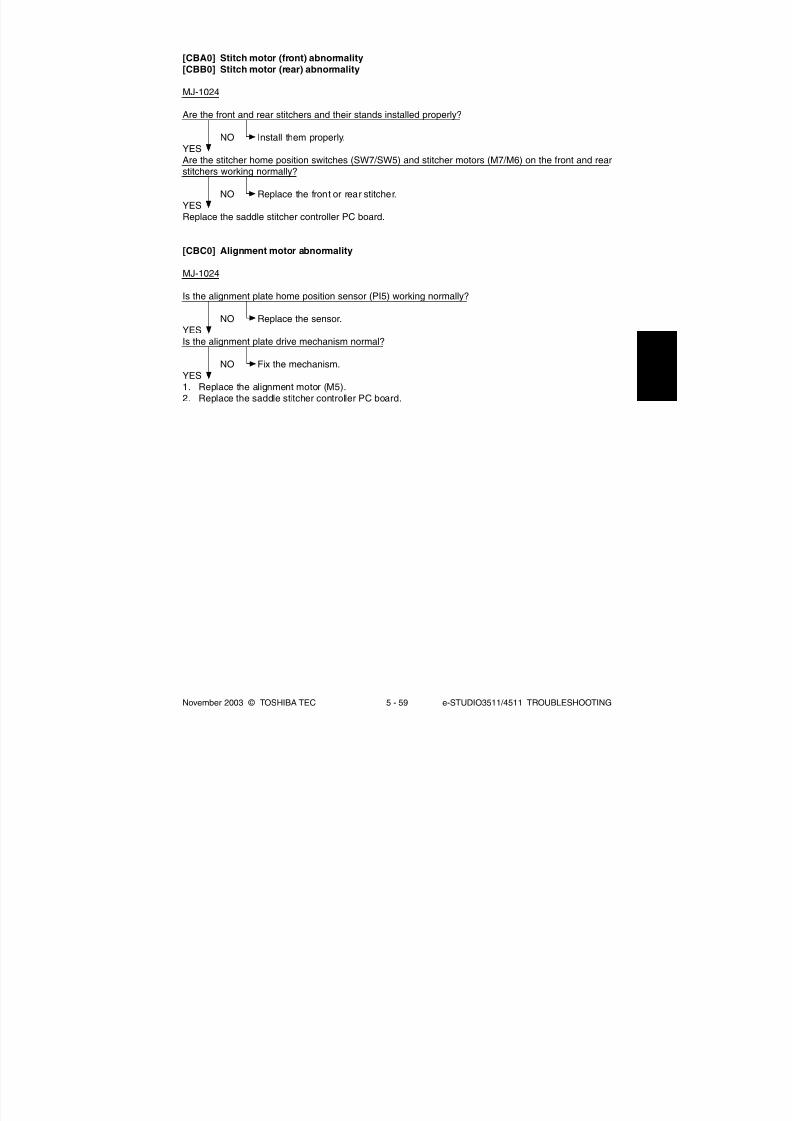
8/2/2019 ES-3511 Service Handbook
http://slidepdf.com/reader/full/es-3511-service-handbook 367/543
November 2003 © TOSHIBA TEC 5 - 59 e-STUDIO3511/4511 TROUBLESHOOTING
[CBA0] Stitch motor (front) abnormality[CBB0] Stitch motor (rear) abnormality
MJ-1024
Are the front and rear stitchers and their stands installed properly?
NO Install them properly.YESAre the stitcher home position switches (SW7/SW5) and stitcher motors (M7/M6) on the front and rearstitchers working normally?
NO Replace the front or rear stitcher.YESReplace the saddle stitcher controller PC board.
[CBC0] Alignment motor abnormality
MJ-1024
Is the alignment plate home position sensor (PI5) working normally?
NO Replace the sensor.YESIs the alignment plate drive mechanism normal?
NO Fix the mechanism.YES1. Replace the alignment motor (M5).2. Replace the saddle stitcher controller PC board.

8/2/2019 ES-3511 Service Handbook
http://slidepdf.com/reader/full/es-3511-service-handbook 368/543
e-STUDIO3511/4511 TROUBLESHOOTING 5 - 60 November 2003 © TOSHIBA TEC
[CBD0] Guide motor abnormality
MJ-1024
Is the guide home position sensor (PI13) working normally?
NO Replace the sensor.
YESIs the guide plate drive mechanism normal?
NO Fix the mechanism.YES1. Replacing the guide motor (M3).2. Replace the saddle stitcher controller PC board.
[CBE0] Paper folding motor abnormality
MJ-1024
Are the paper folding motor clock sensor (PI4) and paper folding home position sensor (PI21)working normally?
NO Replace the sensors.YESIs the paper folding roller drive mechanism normal?
NO Fix the mechanism.YES1. Replacing the paper folding motor (M2).2. Replace the saddle stitcher controller PC board.
[CBF0] Paper positioning plate motor abnormality
MJ-1024
Is the paper positioning plate home position sensor (PI7) working normally?
NO Replace the sensor.YESIs the paper positioning plate drive mechanism normal?
NO Fix the mechanism.
YES1. Replacing the paper positioning plate motor (M4).2. Replace the saddle stitcher controller PC board.
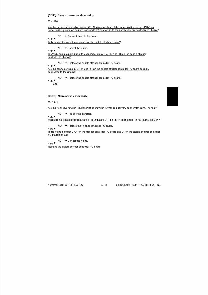
8/2/2019 ES-3511 Service Handbook
http://slidepdf.com/reader/full/es-3511-service-handbook 369/543
November 2003 © TOSHIBA TEC 5 - 61 e-STUDIO3511/4511 TROUBLESHOOTING
[CC10] Microswitch abnormality
MJ-1024
Are the front cover switch (MS31), inlet door switch (SW1) and delivery door switch (SW3) normal?
NO Replace the switches.YESMeasure the voltage between J704-1 (+) and J704-2 (-) on the finisher controller PC board. Is it 24V?
NO Replace the finisher controller PC board.YESIs the wiring between J704 on the finisher controller PC board and J1 on the saddle stitcher controllerPC board correct?
NO Correct the wiring.YES
Replace the saddle stitcher controller PC board.
[CC00] Sensor connector abnormality
MJ-1024
Are the guide home position sensor (PI13), paper pushing plate home position sensor (PI14) andpaper pushing plate top position sensor (PI15) connected to the saddle stitcher controller PC board?
NO Connect them to the board.YESIs the wiring between the sensors and the saddle stitcher correct?
NO Correct the wiring.YESIs 5V DC being supplied from the connector pins J9-7, -10 and -13 on the saddle stitchercontroller PC board?
NO Replace the saddle stitcher controller PC board.YESAre the connector pins J9-8, -11 and -14 on the saddle stitcher controller PC board correctlyconnected to the ground?
NO Replace the saddle stitcher controller PC board.YES
End.
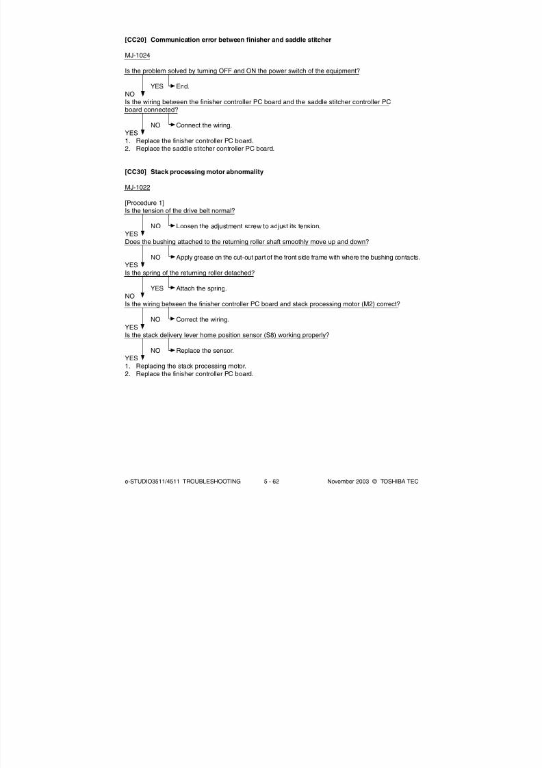
8/2/2019 ES-3511 Service Handbook
http://slidepdf.com/reader/full/es-3511-service-handbook 370/543
e-STUDIO3511/4511 TROUBLESHOOTING 5 - 62 November 2003 © TOSHIBA TEC
[CC20] Communication error between finisher and saddle stitcher
MJ-1024
Is the problem solved by turning OFF and ON the power switch of the equipment?
YES End.
NOIs the wiring between the finisher controller PC board and the saddle stitcher controller PCboard connected?
NO Connect the wiring.YES1. Replace the finisher controller PC board.2. Replace the saddle stitcher controller PC board.
[CC30] Stack processing motor abnormality
MJ-1022
[Procedure 1]Is the tension of the drive belt normal?
NO Loosen the adjustment screw to adjust its tension.YESDoes the bushing attached to the returning roller shaft smoothly move up and down?
NO Apply grease on the cut-out part of the front side frame with where the bushing contacts.YESIs the spring of the returning roller detached?
YES Attach the spring.NOIs the wiring between the finisher controller PC board and stack processing motor (M2) correct?
NO Correct the wiring.YESIs the stack delivery lever home position sensor (S8) working properly?
NO Replace the sensor.YES1. Replacing the stack processing motor.2. Replace the finisher controller PC board.

8/2/2019 ES-3511 Service Handbook
http://slidepdf.com/reader/full/es-3511-service-handbook 371/543
November 2003 © TOSHIBA TEC 5 - 63 e-STUDIO3511/4511 TROUBLESHOOTING
[Procedure 2]Does the bushing attached to the returning roller shaft smoothly move up and down?
NO Apply grease on the cut-out part of the front side frame with where the bushing contacts.YESIs the spring of the returning roller detached?
YES Attach the spring.NOIs the tension of the stack processing motor drive belt normal?
NO Loosen the adjustment screw to adjust its tension.YESIs the returning roller home position sensor (S3) working properly?
NO Replace the sensor.YES1. Replace the stack processing motor.2. Replace the finisher controller PC board.
[CC40] Swing motor abnormality
MJ-1023/1024
Is the swing unit home position sensor (PI35) normal?
NO Replace the sensor.YESIs the wiring between the finisher controller PC board and the swing motor (M36) correct?
NO Correct the wiring.YESIs the swing mechanism normal?
NO Fix the mechanism.YES1. Replace the swing motor.2. Replace the finisher controller PC board.

8/2/2019 ES-3511 Service Handbook
http://slidepdf.com/reader/full/es-3511-service-handbook 372/543
e-STUDIO3511/4511 TROUBLESHOOTING 5 - 64 November 2003 © TOSHIBA TEC
[CC50] Horizontal registration motor abnormality
MJ-1023/1024 (when MJ-6004 is installed)
Is the horizontal registration home position sensor (PI61) working normally?
NO Replace the sensor.
YESIs the wiring between the horizontal registration home position sensor and finisher controllerPC board correct?
NO Correct the wiring.YESIs the horizontal registration mechanism normal?
NO Fix the mechanism.YES1. Replace the horizontal registration motor (M62).2. Replace the punch controller PC board.3. Replace the finisher controller PC board.
[CC60] Punch motor abnormality
MJ-1023/1024 (when MJ-6004 is installed)
Are the punch home position sensor (PI63) and punch motor clock sensor (PI62) working normally?
NO Replace the sensors.YESIs the wiring between the sensors and finisher controller PC board correct?
NO Correct the wiring.YESIs the punching mechanism normal?
NO Fix the mechanism.YES1. Replace the punch motor (M61).2. Replace the punch controller PC board.3. Replace the finisher controller PC board.

8/2/2019 ES-3511 Service Handbook
http://slidepdf.com/reader/full/es-3511-service-handbook 373/543
November 2003 © TOSHIBA TEC 5 - 65 e-STUDIO3511/4511 TROUBLESHOOTING
[CC80] Front jogging motor abnormality/Front aligning plate motor abnormality
MJ-1022 (Front jogging motor abnormality)
Is the front jogging plate home position sensor (S6) working properly?
NO Replace the sensor.
YESIs the wiring between the finisher controller PC board and front jogging motor (M3) correct?
NO Correct the wiring.YESHas the rack run over the stopper of the roll?
YES Fix it.NO1. Replace the front jogging motor.2. Replace the finisher controller PC board.
MJ-1023/1024 (Front aligning plate motor abnormality)
Is the front aligning plate home position sensor (PI36) normal?
NO Replace the sensor.YESIs the wiring between the finisher controller PC board and the front aligning plate motor (M33) correct?
NO Correct the wiring.YESIs there any mechanical problem with the path of aligning plate?
NO Fix the mechanism.YES1. Replace the front aligning plate motor.2. Replace the finisher controller PC board.

8/2/2019 ES-3511 Service Handbook
http://slidepdf.com/reader/full/es-3511-service-handbook 374/543
e-STUDIO3511/4511 TROUBLESHOOTING 5 - 66 November 2003 © TOSHIBA TEC
[CC90] Upper stack tray lift motor abnormality
MJ-1022
Is the wiring between the finisher controller PC board and upper stack tray lift motor (M5) correct?
NO Correct the wiring.
YESAre the front and rear sides of the upper stack tray leveled?
NO Level them.YESIs the upper stack tray lift motor clock sensor (S19) working properly?
NO Replace the sensor.YESIs the stack tray paper height sensor (S10) working properly?
NO Replace the sensor.YESAre the upper stack tray upper limit sensor (S25), upper stack tray full sensor (S23) and stackprocessing safety switch (S26) working properly?
NO Replace the sensor or sensor controller PC board.YESDoes the voltage between the pins J14-1 and -2 on the finisher controller PC board become 24V whenthe upper stack tray lift motor starts rotating?
NO Replace the finisher controller PC board.YESCheck the wiring between the upper stack tray lift motor and finisher controller PC board. If there is noproblem, replace the upper stack tray lift motor.

8/2/2019 ES-3511 Service Handbook
http://slidepdf.com/reader/full/es-3511-service-handbook 375/543
November 2003 © TOSHIBA TEC 5 - 67 e-STUDIO3511/4511 TROUBLESHOOTING
[CCA0] Lower stack tray lift motor abnormality
MJ-1022
Is the wiring between the finisher controller PC board and lower stack tray lift motor (M7) correct?
NO Correct the wiring.
YESAre the front and rear sides of the lower stack tray leveled?
NO Level them.YESIs the lower stack tray lift motor clock sensor (S9) working properly?
NO Replace the sensor.YESIs the stack tray paper height sensor (S10) working properly?
NO Replace the sensor.YESAre the lower stack tray upper limit sensor (S13) and lower stack tray full sensor (S23) working properly?
NO Replace the sensor or sensor controller PC board.YESDoes the voltage between the pins J3-1 and -2 on the finisher controller PC board become 24V when thelower stack tray lift motor starts rotating?
NO Replace the finisher controller PC board.YESCheck the wiring between the upper stack tray lift motor and finisher controller PC board. If there is noproblem, replace the motor.
[CCB0] Rear jogging motor abnormality
MJ-1022
Is the rear jogging plate home position sensor (S7) working properly?
NO Replace the sensor.YESIs the wiring between the finisher controller PC board and rear jogging motor (M4) correct?
NO Correct the wiring.
YESHas the rack run over the stopper of the roll?
YES Fix it.NO1. Replace the rear jogging motor.2. Replace the finisher controller PC board.

8/2/2019 ES-3511 Service Handbook
http://slidepdf.com/reader/full/es-3511-service-handbook 376/543
e-STUDIO3511/4511 TROUBLESHOOTING 5 - 68 November 2003 © TOSHIBA TEC
[CCD0] Stack ejection motor abnormality
MJ-1023/1024
Is the shutter home position sensor (PI45) normal?
NO Replace the sensor.
YESAre the wirings between the finisher controller PC board and the stack ejection motor (M32)/shutterclutch (CL31) correct?
NO Correct the wirings.YESIs there any problem with the shutter mechanism?
YES Fix the shutter mechanism.NO1. Replace the stack ejection motor and shutter clutch.2. Replace the finisher controller PC board.
[CCE0] Rear end assist motor abnormality
MJ-1023/1024
Is the rear end assist guide home position sensor (PI39) normal?
NO Replace the sensor.YESIs the wiring between the finisher controller PC board and the rear end assist motor (M39) correct?
NO Correct the wiring.
YESIs there any problem with the rear end assist mechanism?
YES Fix the rear end assist mechanism.NO1. Replace the rear end assist motor.2. Replace the finisher controller PC board.

8/2/2019 ES-3511 Service Handbook
http://slidepdf.com/reader/full/es-3511-service-handbook 377/543
November 2003 © TOSHIBA TEC 5 - 69 e-STUDIO3511/4511 TROUBLESHOOTING
[CCF0] Gear change motor abnormality
MJ-1023/1024
Is the gear change home position sensor (PI49) normal?
NO Replace the sensor.
YESIs the wiring between the finisher controller PC board and the gear change motor (M40) correct?
NO Correct the wiring.YESIs there any problem with the gear change mechanism?
YES Fix the gear change mechanism.NO1. Replace the gear change motor.2. Replace the finisher controller PC board.
[CE00] Communication error between finisher and puncher unit
MJ-1023/1024 (When MJ-6004 is installed)
Is the problem solved by turning OFF and ON the power of the equipment?
YES End.NOIs the wiring between the finisher controller PC board and punch controller PC board correct?
NO Correct the wiring.YES
1. Replace the finisher controller PC board.2. Replace the punch controller PC board.

8/2/2019 ES-3511 Service Handbook
http://slidepdf.com/reader/full/es-3511-service-handbook 378/543
e-STUDIO3511/4511 TROUBLESHOOTING 5 - 70 November 2003 © TOSHIBA TEC
5.1.17 Image control related service call
(1) Based on the procedure of [CE10], [CE20] and [CE40] described below, check the status and take
appropriate actions. And then perform the forced performing of image quality closed-loop control
according to the following procedure.
1. While pressing [0] and [5] simultaneously, turn ON the power.
2. Key in [395], and then press the [START] button. Confirm that the image quality control has
finished normally.
(2) After confirming the items in (1), clear the abnormal detection counter of image quality control.
1. While pressing [0] and [8] simultaneously, turn ON the power.
2. Key in [573], and then press the [START] button.
3. Rewrite the displayed status counter from "1" - "16" to "0", and then press the [ENTER] or
[INTERRUPT] button.
4. Key in [574], and then press the [START] button.
5. Rewrite the displayed status counter from "1" - "16" to "0", and then press the [ENTER] or
[INTERRUPT] button.
6. Key in [575], and then press the [START] button.
7. Rewrite the displayed status counter from "1" - "16" to "0", and then press the [ENTER] or
[INTERRUPT] button.
8. Key in [576], and then press the [START] button.
9. Rewrite the displayed status counter from "1" - "16" to "0", and then press the [ENTER] or
[INTERRUPT] button.
[CE10] Image quality sensor abnormality (OFF level)
Is the connector of the image quality sensor, or the connector CN345 on the LGC board disconnected?Is the harness between the LGC board and the image quality sensor, or the harness between the LGCboard and the switching power supply open circuited?
YES Connect the connector securely. Replace the harness.
NOIs the output voltage from the 12V-power supply normal?
NO Check the power supply system and replace the switching power supply.
YES1. Replace the image quality sensor.2. Replace the LGC board.

8/2/2019 ES-3511 Service Handbook
http://slidepdf.com/reader/full/es-3511-service-handbook 379/543
November 2003 © TOSHIBA TEC 5 - 71 e-STUDIO3511/4511 TROUBLESHOOTING
[CE20] Image quality sensor abnormality (no pattern level)
1. Check if the transfer belt or transfer belt unit are securely installed.2. Check for any abnormal stain caused by poor cleaning, large flaw or break on the transfer belt
surface.3. Check if the drum and the transfer belt are rotating. If any abnormality is found, correct any
mechanical problem.
Is the connectors CN345 on the LGC board disconnected?Is the connector of the image quality sensor disconnected or the surface of the sensor stained?Is the harness between the LGC board and the image quality sensor open circuited?Is the shutter of image quality sensor opening and closing normally? Is the shutter damaged?
<Procedure>1. Take off the transfer belt unit so that the image quality sensor unit can be easily
seen.2. While pressing the digital keys [0] and [3] simultaneously, turn the power ON.3. Key in “430”.4. The shutter is opened and closed repeatedly by pressing the [START] button
repeatedly.
YES Connect the connector securely. Replace the harness. Clean the sensor.Replace the shutter if it is damaged.Replace the shutter solenoid if its operation is defective.
NOIs the output voltage from the 12V-power supply normal?
NO Check the power supply system, and replace the switching power supply.
YES1. Replace the image quality sensor.2. Replace the LGC board.

8/2/2019 ES-3511 Service Handbook
http://slidepdf.com/reader/full/es-3511-service-handbook 380/543
e-STUDIO3511/4511 TROUBLESHOOTING 5 - 72 November 2003 © TOSHIBA TEC
[CE40] Image quality control test pattern abnormality
(1) Use "Image quality control abnormal detection counter Y to K display/0 clearing (08-573 to 576)"to check the abnormal occurring condition for each color.
(2) Check “Output value display of image quality sensor / Low-density pattern (05-391-0 to 3)” tocheck if the low-density pattern abnormality occurs for each color. The values under 320 for Y, M
and C, and under 220 for K are defined as low-density pattern abnormality.
Under 320 (Y, M and C)Under 220 (K)
Low-density pattern abnormalityCheck the transfer belt. If the cleaning is poor, correct the transfer beltaround its cleaning blade.
320 or above (Y, M and C)220 or above (K) To (9)
(3) Check “Output value display of image quality sensor / High-density pattern (05-390-0 to 3)” tocheck if the high-density pattern abnormality occurs for each color and identify the color whichpattern is abnormal. If the value is 630 or above, it is defined as high-density pattern abnormality.
(4) Set the values of “Image quality closed-loop control / Contrast voltage (08-556)” and “Imagequality closed-loop control / Laser power (08-557)” to “0” (Invalid).
(5) Perform “Enforced performing of image quality open-loop control (05-394)”.
(6) Output the image quality control test pattern (04-270) more than one time and check the patch ofthe color identified in step (3) to see if the image is abnormal (Note).
Abnormal
Correct the items related to the image.
Normal To (9)(7) Replace the image quality sensor.
(8) Set the values of “Image quality closed-loop control / Contrast voltage (08-556)” and “Imagequality closed-loop control / Laser power (08-557)” to “1” (Valid).
(9) Perform “Enforced performing of image quality open-loop control (05-394)” and make sure it iscompleted normally. (Error [CE40] does not appear.) Then perform “Automatic gamma adjustment“ ( Chapter 3.5.1 and 3.6.1).
(10) Clear all "Image quality control abnormal detection counter Y to K display/0 clearing (08-573 to576)".
Note
Abnormal image: Blank print, Solid print, White banding, Color banding, White spots, Poor transfer,
Uneven image density, Faded image (low density), Uneven light distr ibution, Blotched
image
04/05

8/2/2019 ES-3511 Service Handbook
http://slidepdf.com/reader/full/es-3511-service-handbook 381/543
November 2003 © TOSHIBA TEC 5 - 73 e-STUDIO3511/4511 TROUBLESHOOTING
[CE50] Temperature/humidity sensor abnormality
Is the connector CN361 on the LGC board or the connector of the temperature/humidity sensordisconnected?Is the harness between the LGC board and the temperature/humidity sensor disconnected ?
YES Connect the connector securely. Replace the harness.
NO1. Replace the temperature/humidity sensor.2. Replace the LGC board.
[CE90] Drum thermistor abnormality
Is the connector CN361 on the LGC board, or the connector of the drum thermistor disconnected?Is the harness between the LGC board and the drum thermistor disconnected?
YES Connect the connector securely. Replace the harness.NO
1. Replace the drum thermistor.2. Replace the LGC board.

8/2/2019 ES-3511 Service Handbook
http://slidepdf.com/reader/full/es-3511-service-handbook 382/543
e-STUDIO3511/4511 TROUBLESHOOTING 5 - 74 November 2003 © TOSHIBA TEC
5.1.18 Copy process related service call
[C360] Charger cleaner motor abnormality
(1) Check if the main charger is installed normally.(2) Check if the charger wire is broken.(3) Check if any of the connector pins of the charger cleaner front/rear position detection switch is
disconnected.(4) Check if the cleaning pads are damaged or removed.(5) Check if any of the connector pins of the charger cleaner motor is disconnected.(6) Replace the charger cleaner motor.(7) Replace the LGC board.
[C970] High-voltage transformer abnormality
(1) Is the main charger installed securely?(2) Check if the spring of high-voltage supply contact point is deformed.(3) Check if the charger wire is broken or the main charger grid is deformed.(4) Check if any foreign matter is on the charger wire or main charger grid.
[CEA0] Revolver home position detection abnormality
Is the revolver home position sensor working properly? (Perform the input check: 03-[FAX]ON/[2]/[C])
NO 1. Check if the connector or joint connector of the revolver home position sensor isdisconnected.
2. Check if the connector CN361 on the LGC board is disconnected.3. Check if the connector pins are disconnected or the wires of harnesses are
open circuited.
4. Check if the conductor pattern on the LGC board is short circuited or opencircuited.
5. Replace the revolver home position sensor.6. Replace the LGC board.
YES1. Check if the conductor pattern on the LGC board is short circuited or open circuited.2. Replace the LGC board.

8/2/2019 ES-3511 Service Handbook
http://slidepdf.com/reader/full/es-3511-service-handbook 383/543
November 2003 © TOSHIBA TEC 5 - 75 e-STUDIO3511/4511 TROUBLESHOOTING
[CEB0] Black developer unit lifting movement abnormality
Is the black developer lifting clutch working properly? (Perform the output check: 03-433)
NO 1. Check if the connector of the black developer lifting clutch is disconnected.2. Check if the connector CN362 on the LGC board is disconnected.3. Check if the connector pins are disconnected or the wires of harnesses are open
circuited.4. Check if the conductor pattern on the LGC board is short circuited or open
circuited.5. Replace the black developer lifting clutch.6. Replace the LGC board.
YESAre the black developer contact position detection sensor and black developer contact timingdetection sensor working properly? (Perform the input check: 03-[FAX]ON/[1]/[C], /[1]/[B]
NO 1. Check if the connectors of the black developer contact position detection sensoror black developer contact timing detection sensor are disconnected.
2. Check if the connector CN361 on the LGC board is disconnected.3. Check if the connector pins are disconnected or the wires of harnesses are open
circuited.4. Check if the conductor pattern on the LGC board is short circuited or open
circuited.5. Replace the black developer contact position detection sensor and black devel-
oper contact timing detection sensor.6. Replace the LGC board.
YES1. Check if the conductor pattern on the LGC board is short circuited or open circuited.2. Replace the LGC board.

8/2/2019 ES-3511 Service Handbook
http://slidepdf.com/reader/full/es-3511-service-handbook 384/543
e-STUDIO3511/4511 TROUBLESHOOTING 5 - 76 November 2003 © TOSHIBA TEC
[CEC0] 2nd transfer roller position detection abnormality
Is the 2nd transfer roller contact clutch working properly? (Perform the output check: 03-435)
NO 1. Check if the connector or joint connectors of the 2nd transfer contact clutch aredisconnected.
2. Check if the connector CN345 on the LGC board is disconnected.
3. Check if the connector pins are disconnected or the wires of harnesses are opencircuited.
4. Check if the conductor pattern on the LGC board is short circuited or opencircuited.
5. Replace the 2nd transfer roller contact clutch.6. Replace the LGC board.
YESIs the 2nd transfer roller position detection sensor working properly? (Perform the input check:03-[FAX]ON/[1]/[A])
NO 1. Check if the connector or joint connectors of the 2nd transfer roller position detec-tion sensor are disconnected.
2. Check if the connector CN345 on the LGC board is disconnected.3. Check if the connector pins are disconnected or the wires of harnesses are open
circuited.4. Check if the conductor pattern on the LGC board is short circuited or open
circuited.5. Replace the 2nd transfer roller position detection sensor.6. Replace the LGC board.
YES1. Check if the conductor pattern on the LGC board is short circuited or open circuited.2. Replace the LGC board.

8/2/2019 ES-3511 Service Handbook
http://slidepdf.com/reader/full/es-3511-service-handbook 385/543
November 2003 © TOSHIBA TEC 5 - 77 e-STUDIO3511/4511 TROUBLESHOOTING
[CEE0] Transfer belt position detection abnormality (Normal speed)[CEE1] Transfer belt position detection abnormality (When decelerating)
If the error [CEE0] has occurred, check the transfer belt home position sensor-1. If the error [CEE1]
has occurred, check the transfer belt home position sensor-2.
Is there any stain or scratch on the reflection tape inside the transfer belt?
YES Clean the transfer belt or replace it.Replace the cleaning pad if it is excessively stained.
NOAre the transfer belt home position sensors-1 and -2 stained?
YES Clean them.NOAre the transfer belt home position sensors-1 and -2 working properly? (Perform the input check:03-[FAX]ON/[9]/[H])
NO 1. Check if the connectors or joint connectors of the transfer belt home position
sensors-1 and -2 are disconnected.2. Check if the connector CN361 on the LGC board is disconnected.3. Check if the connector pins are disconnected or the wires of harnesses are open
circuited.4. Check if the conductor pattern on the LGC board is short circuited or open
circuited.5. Replace the transfer belt home position sensor-1 and -2.6. Replace the LGC board.
YES1. Check if the conductor pattern on the LGC board is short circuited or open circuited.2. Replace the LGC board.
[CEF0] Revolver motor abnormality
Is the revolver motor working? (Perform the output check: 03-450)
NO 1. Check if the connector of the revolver motor is disconnected.2. Check if the connectors CN435 and J434 on the DRV board are disconnected.3. Check if the connector CN360 on the LGC board is disconnected.4. Check if the connector pins are disconnected or the harnesses are open circuited.5. Check if the conductor patterns on the DRV board and LGC board are short
circuited or open circuited.6. Replace the revolver motor.7. Replace the DRV board and LGC board.
YES1. Check if the conductor patterns on the DRV board and LGC board are short circuited or open
circuited.2. Replace the DRV board and LGC board.

8/2/2019 ES-3511 Service Handbook
http://slidepdf.com/reader/full/es-3511-service-handbook 386/543
e-STUDIO3511/4511 TROUBLESHOOTING 5 - 78 November 2003 © TOSHIBA TEC
5.1.19 Toner density control related service call
[CF20] Toner density detection voltage abnormality
(1) Specify the developer unit with the abnormality by checking the setting values of 08-824-0 to 08-824-2. (When the value is “1”, an abnormality occurs.)
(2) Correct the defective section of the unit specified in (1) with the following procedure.
Is the developer material transported properly? Is the form of magnetic brush is normal?
NO 1. Check if the amount of the developer material is normal or any foreign matter ismixed in.
2. Correct the transport mechanism of developer material.3. Check the polar position and correct if necessary.
YESIs the color auto-toner sensor stained?
YES Clean it.
NOIs the color auto-toner sensor shutter solenoid working normally? (Perform the output check: 03-125/ 175)Is the color auto-toner sensor working?
NO 1. Check if the connectors or joint connectors of the color auto-toner sensor shuttersolenoid and color auto-toner sensor are disconnected.
2. Check if the connector CN356 on the LGC board is disconnected.3. Check if the connector pins are disconnected or the harnesses are open circuited.4. Replace the color auto-toner sensor shutter solenoid.5. Check if the conductor pattern on the LGC board is short circuited or open
circuited.6. Replace the LGC board.7. Replace the color auto-toner sensor and perform “Enforced correction of color
auto-toner sensor light amount (05-208)”.YESIs the color auto-toner sensor shutter opening position correct? (Perform the output check: 03-125/175)
NO Adjust the install position of solenoid so that the sensor holder will touch and facethe positioning component when opening the shutter.
YES1. Check if the conductor pattern on the LGC board is short circuited or open circuited.2. Replace the LGC board.
(3) When the correction is completed, reset the values of 08-824-0 to 08-824-2 from “1” to “0” to clear
the abnormality.

8/2/2019 ES-3511 Service Handbook
http://slidepdf.com/reader/full/es-3511-service-handbook 387/543
November 2003 © TOSHIBA TEC 5 - 79 e-STUDIO3511/4511 TROUBLESHOOTING
[CF30] Reference plate detection voltage abnormality
Are the reference plate and color auto-toner sensor stained?
YES Clean them.NOIs the color auto-toner sensor shutter solenoid working normally? (Perform the output check: 03-125/
175)Is the color auto-toner sensor working?
NO 1. Check if the connectors or joint connectors of the color auto-toner sensor shuttersolenoid and color auto-toner sensor are disconnected.
2. Check if the connector CN356 on the LGC board is disconnected.3. Check if the connector pins are disconnected or the harnesses are open circuited.4. Replace the color auto-toner sensor shutter solenoid.5. Check if the conductor pattern on the LGC board is short circuited or open circuited.6. Replace the LGC board.7. Replace the color auto-toner sensor and perform “Enforced correction of color
auto-toner sensor light amount (05-208)”.YESIs the color auto-toner sensor shutter closing position correct? (Perform the output check: 03-125/175)
NO Adjust the install position of solenoid so that the gap between the sensor holder andstopper will be 1.0 mm when closing the shutter.
YES1. Replace the LGC board.2. Replace the reference plate and perform “Initialization of color auto-toner sensor light amount
correction target value (05-207)”.

8/2/2019 ES-3511 Service Handbook
http://slidepdf.com/reader/full/es-3511-service-handbook 388/543
e-STUDIO3511/4511 TROUBLESHOOTING 5 - 80 November 2003 © TOSHIBA TEC
[CF40] Light amount correction voltage abnormality
(1) Specify the developer unit with the abnormality by checking the setting values of 08-823-0 to 08-823-2. (When the value is “1”, an abnormality occurs.)
(2) Correct the defective section of the unit specified in (1) with the following procedure.
Is the developer unit inserted properly?
NO Insert it properly.YESIs the developer material transported properly? Is the form of magnetic brush is normal?
NO 1. Check if the amount of the developer material is normal or any foreign matter ismixed in.
2. Correct the transport mechanism of developer material.3. Check the polar position and correct if necessary.
YESIs the color auto-toner sensor stained?
YES Clean it.NOIs the color auto-toner sensor shutter solenoid working normally? (Perform the output check: 03-125/ 175)Is the color auto-toner sensor working?
NO 1. Check if the connectors or joint connectors of the color auto-toner sensor shuttersolenoid and color auto-toner sensor are disconnected.
2. Check if the connector CN356 on the LGC board is disconnected.3. Check if the connector pins are disconnected or the harnesses are open circuited.4. Replace the color auto-toner sensor shutter solenoid.5. Check if the conductor pattern on the LGC board is short circuited or open
circuited.6. Replace the LGC board.7. Replace the color auto-toner sensor and perform “Enforced correction of color
auto-toner sensor light amount (05-208)”.YESIs the color auto-toner sensor shutter opening position correct? (Perform the output check: 03-125/175)
NO Adjust the install position of solenoid so that the sensor holder will touch and facethe positioning component when opening the shutter.
YES1. Replace the LGC board.2. Replace the reference plate and perform “Initialization of color auto-toner sensor light amount
correction target value (05-207)”.
(3) When the correction is completed, reset the values of 08-823-0 to 08-823-2 from “1” to “0” to clearthe abnormality.

8/2/2019 ES-3511 Service Handbook
http://slidepdf.com/reader/full/es-3511-service-handbook 389/543
November 2003 © TOSHIBA TEC 5 - 81 e-STUDIO3511/4511 TROUBLESHOOTING
[CF50] Color auto-toner sensor abnormality
Are the connector of color auto-toner sensor, joint connector and connector CN356 on the LGC boardconnected normally?
NO 1. Reconnect the connectors.2. Correct or replace if the connector pins are disconnected or harnesses are open
circuited.YESAre the color auto-toner sensor and reference plate stained?
YES Clean them.NOIs the color auto-toner sensor shutter solenoid working normally?(Perform the output check: 03-125/175)
NO 1. Check if the connectors or joint connectors of the color auto-toner sensor shuttersolenoid and color auto-toner sensor are disconnected.
2. Check if the connector CN356 on the LGC board is disconnected.3. Check if the connector pins are disconnected or the harnesses are open circuited.4. Check if the conductor pattern on the LGC board is short circuited or open
circuited.5. Replace the color auto-toner sensor shutter solenoid.6. Replace the LGC board.
YESIs the color auto-toner sensor shutter closing position correct? (Perform the output check: 03-125/175)
NO Adjust the install position of solenoid so that the gap between the sensor holder andstopper will be 1.0 mm when closing the shutter.
YES1. Check if the conductor pattern on the LGC board is short circuited or open circuited.2. Replace the LGC board.
3. Replace the reference plate and perform “Initialization of color auto-toner sensor light amountcorrection target value (05-207)”.
4. Replace the color auto-toner sensor and perform “Enforced correction of color auto-toner sensorlight amount (05-208)”.

8/2/2019 ES-3511 Service Handbook
http://slidepdf.com/reader/full/es-3511-service-handbook 390/543
e-STUDIO3511/4511 TROUBLESHOOTING 5 - 82 November 2003 © TOSHIBA TEC
5.1.20 Other service call
[F100] HDD format error
(1) Check if the HDD is mounted.(2) Check if the specified HDD is mounted.(3) Check if the connector pins of the HDD are bent.
(4) Check if the connectors CN112, CN113 on the SYS board is disconnected.(5) Replace the harness.(6) Format the HDD. (Key in "2" at 08-690.)(7) Replace the HDD.(8) Replace the SYS board.
[F101] HDD unmounted[F102] HDD start error[F103] HDD transfer time-out[F104] HDD data error[F105] HDD other error
(1) Check if the connectors of the HDD are disconnected.(2) Check if the connector pins are disconnected or the wires of harnesses are open circuited.(3) Perform the bad sector check (08-694). If the check result is OK, recover the data in the HDD. If
the check result is failed, replace the HDD.(4) Replace the SYS board.
[F106] Point and Print partition damage
(1) Turn the power OFF and start up the Setting Mode (08).(2) Key in “662” and press the [START] button. (Partition clearing is performed.)(3) Restart the equipment.(4) Access TopAccess. Click the [Administration] tab, and then click the Maintenance Menu to open.
Then install the “Point and Print” driver.
[F107] / SHR partition damage
Initialize the Electronic Filing using the Setting Mode (08-666).
[F108] /SHA partition damage
Initialize the shared folder using the Setting Mode (08-667).
[F120] Database abnormality
(1) Rebuild the databases. (Perform 08-684.)(2) If the error is not recovered, initialize the HDD. (Enter “2” at 08-690.)
* When “Rebuilding all databases (08-684)” is performed, all data in the Address Book and Mailboxare deleted. Make sure to back up these data in advance of rebuilding and restore the data afterrebuilding.

8/2/2019 ES-3511 Service Handbook
http://slidepdf.com/reader/full/es-3511-service-handbook 391/543
November 2003 © TOSHIBA TEC 5 - 83 e-STUDIO3511/4511 TROUBLESHOOTING
5.1.21 Error in Internet FAX / Scanning Function
Notes:
1. When initializing the Electronic Filing (Setting Mode (08-666)), all data in the Electronic Filing
are erased. Back up the data in the Electronic Filing by using the Electronic Filing Function of
TopAccess before the initialization.
2. When initializing the shared folder (Setting Mode (08-667)), all data in the shared folder are
erased. Back up the data in the shared folder by using Explorer before the initialization.
3. When formatting the HDD (Setting Mode (08-690)), all data in the shared folder, Electronic
Filing, Address Book, template, etc. are erased. Back up these data before the initialization.
Note that some of data cannot be backed up ( Page 5-1).
(1) Internet FAX related error
[1C10] System access abnormality[1C32] File deletion failure
Turn the power OFF and then back ON. Perform the job in error again.If the error still occurs, first, check if there are no jobs existing and then perform the HDD formatting(08-690).
[1C11] Insufficient memory
When there are running jobs, perform the job in error again after the completion of the running jobs.If the error still occurs, turn the power OFF and then back ON, and perform the job again.
[1C12] Message reception error[1C13] Message transmission error
Turn the power OFF and then back ON. Perform the job in error again.
[1C14] Invalid parameter
When a template is used, form the template again.If the error still occurs, turn the power OFF and then back ON, and perform the job again.
[1C15] Exceeding file capacity
Reset and extend the "Maximum send to E-mail/iFAX size" or reduce the number of pages andperform the job again.

8/2/2019 ES-3511 Service Handbook
http://slidepdf.com/reader/full/es-3511-service-handbook 392/543
e-STUDIO3511/4511 TROUBLESHOOTING 5 - 84 November 2003 © TOSHIBA TEC
[1C20] System management module access abnormality[1C21] Job control module access abnormality[1C22] Job control module access abnormality
Turn the power OFF and then back ON. Perform the job in error again.Check if there are no other running jobs and perform the HDD formatting (08-690).If the recovery is still not completed, replace the SYS board.
[1C30] Directory creation failure[1C31] File creation failure[1C33] File access failure
Check if the access privilege to the storage directory is writable.Check if the server or local disk has a sufficient space in disk capacity.
[1C40] Image conversion abnormality
Turn the power OFF and then back ON. Perform the job in error again.Replace the main memory and perform the job again.
[1C60] HDD full failure during processing
Reduce the number of pages of the job in error and perform the job again.Check if the server or local disk has a sufficient space in disk capacity.
[1C61] Address Book reading failure
Turn the power OFF and then back ON. Perform the job in error again.Reset the data in the Address Book and perform the job again.
[1C62] Memory acquiring failure
Check if there is any job being performed and perform the job in error again.Turn the power OFF and then back ON. Perform the job in error again.Replace the main memory and perform the job again.
[1C63] Terminal IP address unset
Reset the Terminal IP address.Turn the power OFF and then back ON. Perform the job in error again.

8/2/2019 ES-3511 Service Handbook
http://slidepdf.com/reader/full/es-3511-service-handbook 393/543
November 2003 © TOSHIBA TEC 5 - 85 e-STUDIO3511/4511 TROUBLESHOOTING
[1C64] Terminal mail address unset
Reset the Terminal mail address.Turn the power OFF and then back ON. Perform the job in error again.
[1C65] SMTP address unset
Reset the SMTP address and perform the job.Turn the power OFF and then back ON. Perform the job in error again.
[1C66] Server time time-out error
Check if the SMTP server is operating properly.
[1C67] NIC time time-out error[1C68] NIC access error[1C6D] System error
Turn the power OFF and then back ON. Perform the job in error again.If the error still occurs, replace the NIC board.
[1C69] SMTP server connection error
Reset the login name or password of SMTP server and perform the job again.Check if the SMTP server is operating properly.
[1C6A] HOST NAME error
Check if there is an illegal character in the device name.Delete the illegal character and reset the appropriate device name.
[1C6B] Terminal mail address error
Check if there is an illegal character in the Terminal mail address.Delete the illegal character and reset the appropriate Terminal mail address, then perform the jobagain.
[1C6C] Destination mail address error
Check if there is an illegal character in the Destination mail address.Delete the illegal character and reset the appropriate Destination mail address, then perform the jobagain.

8/2/2019 ES-3511 Service Handbook
http://slidepdf.com/reader/full/es-3511-service-handbook 394/543
e-STUDIO3511/4511 TROUBLESHOOTING 5 - 86 November 2003 © TOSHIBA TEC
[1C70] SMTP client OFF
Set the SMTP valid and perform the job again.
[1C80] Internet FAX transmission failure when processing E-mail job received
Reset the "Received InternetFax Forward".
[1C81] Onramp Gateway transmission failure
Reset the mail box.
[1C82] Internet FAX transmission failure when processing FAX job received
Reset the "Received Fax Forward".
[1CC1] Power failure
Check if the power cable is connected properly and it is inserted securely.Check if the power voltage is unstable.

8/2/2019 ES-3511 Service Handbook
http://slidepdf.com/reader/full/es-3511-service-handbook 395/543
November 2003 © TOSHIBA TEC 5 - 87 e-STUDIO3511/4511 TROUBLESHOOTING
(2) RFC related error
[2500] HOST NAME error (RFC: 500) / Destination mail address error (RFC: 500) / Terminalmail address error (RFC: 500)
[2501] HOST NAME error (RFC: 501) / Destination mail address error (RFC: 501) / Terminalmail address error (RFC: 501)
Check if the Terminal mail address and Destination mail address are correct.Check if the mail server is operating properly.Turn the power OFF and then back ON. Perform the job in error again.
[2503] Destination mail address error (RFC: 503)[2504] HOST NAME error (RFC: 504)[2551] Destination mail address error (RFC: 551)
Check if the mail server is operating properly.Turn the power OFF and then back ON. Perform the job in error again.
If the error still occurs, replace the NIC board.
[2550] Destination mail address error (RFC: 550)
Check the state of the mail box in the mail server.
[2552] Terminal/Destination mail address error (RFC: 552)
Turn the power OFF and then back ON. Perform the job in error again.
If the error still occurs, replace the NIC board.
[2553] Destination mail address error (RFC: 553)
Check if there is an illegal character in the mail box in the mail server.

8/2/2019 ES-3511 Service Handbook
http://slidepdf.com/reader/full/es-3511-service-handbook 396/543
e-STUDIO3511/4511 TROUBLESHOOTING 5 - 88 November 2003 © TOSHIBA TEC
(3) Electronic Filing related error
[2B10] No applicable job error in Job control module[2B11] JOB status abnormality[2B20] File library function error[2B30] Insufficient disk space in /SHR partition[2BC0] Fatal failure occurred
[2BC1] System management module resource acquiring failure
Erase some data in the Electronic Filing and perform the job in error again (in case of [2B30]).Turn the power OFF and then back ON. Perform the job in error again.Check if there are no other running jobs and perform the HDD formatting (08-690).If the recovery is still not completed, replace the SYS board.
[2B50] Image library error[2B90] Insufficient memory capacity
Turn the power OFF and then back ON. Perform the job in error again.If the error still occurs, replace the main memory.Perform the job in error again.Check if there are no other running jobs and initialize the Electronic Filing using the Setting Mode (08-666).
[2B31] Status of specified Electronic Filing or folder is undefined or being created/deleted
Check if the specified Electronic Filing or folder exists. (If no, this error would not occur.)Delete the specified Electronic Filing or folder.Perform the job in error again.
If the specified Electronic Filing or folder can not be deleted, initialize the Electronic Filing using theSetting Mode (08-666).
[2B32] Electronic Filing printing failure: Specified document can not be printed because ofclient's access (being edited, etc.)
Check if the specified document exists. (If no, this error would not occur.)Delete the specified document.Perform the job in error again.If the specified document can not be deleted, initialize the Electronic Filing using the Setting Mode(08-666).
8/2/2019 ES-3511 Service Handbook
http://slidepdf.com/reader/full/es-3511-service-handbook 397/543
November 2003 © TOSHIBA TEC 5 - 89 e-STUDIO3511/4511 TROUBLESHOOTING
[2B51] List library error
Check if the Function List can be printed out.If it can be printed out, perform the job in error again.If it can not be printed out, replace the main memory.If the recovery is still not completed, perform the HDD formatting (08-690).
[2BA0] Invalid Box password
Check if the password is correct.Reset the password.When this error occurs when printing the data in the Electronic Filing, perform the printing with theadministrator's password.If the recovery is still not completed or in case of invalid password for the operation other than printing(opening the file, etc.), initialize the Electronic Filing using the Setting Mode (08-666).
[2BB1] Power failure[2BD0] Power failure occurred during restoring of Electronic Filing
Check if the power cable is connected properly and it is inserted securely.Check if the power voltage is unstable.
[2BE0] Machine parameter reading error
Turn the power OFF and then back ON. Perform the job in error again.
[2BF0] Exceeding maximum number of pages
Reduce the number of inserting pages and perform the job again.
[2BF1] Exceeding maximum number of documents
Backup the documents in the box or folder to PC or delete them.
[2BF2] Exceeding maximum number of folders
Backup the folders in the box or folder to PC or delete them.
04/05

8/2/2019 ES-3511 Service Handbook
http://slidepdf.com/reader/full/es-3511-service-handbook 398/543
e-STUDIO3511/4511 TROUBLESHOOTING 5 - 90 November 2003 © TOSHIBA TEC
(4) E-mail related error
[2C10] System access abnormality[2C32] File deletion failure
Turn the power OFF and then back ON. Perform the job in error again.If the error still occurs, first, check if there are no jobs existing and then perform the HDD formatting
(08-690).
[2C11] Insufficient memory
When there are running jobs, perform the job in error again after the completion of the running jobs.If the error still occurs, turn the power OFF and then back ON, and perform the job again.
[2C12] Message reception error[2C13] Message transmission error
Turn the power OFF and then back ON. Perform the job in error again.
[2C14] Invalid parameter
When a template is used, form the template again.If the error still occurs, turn the power OFF and then back ON, and perform the job again.
[2C15] Exceeding file capacity
Reset and extend the "Maximum send to E-mail/iFAX size" or reduce the number of pages andperform the job again.
[2C20] System management module access abnormality[2C21] Job control module access abnormality[2C22] Job control module access abnormality
Turn the power OFF and then back ON. Perform the job in error again.Check if there are no other running jobs and perform the HDD formatting (08-690).
If the recovery is still not completed, replace the SYS board.
[2C30] Directory creation failure[2C31] File creation failure[2C33] File access failure
Check if the access privilege to the storage directory is writable.Check if the server or local disk has a sufficient space in disk capacity.

8/2/2019 ES-3511 Service Handbook
http://slidepdf.com/reader/full/es-3511-service-handbook 399/543
November 2003 © TOSHIBA TEC 5 - 91 e-STUDIO3511/4511 TROUBLESHOOTING
[2C40] Image conversion abnormality[2C62] Memory acquiring failure
Turn the power OFF and then back ON. Perform the job in error again.Replace the main memory and perform the job again.
[2C60] HDD full failure during processing
Reduce the number of pages of the job in error and perform the job again.Check if the server or local disk has a sufficient space in disk capacity.
[2C61] Address Book reading failure
Turn the power OFF and then back ON. Perform the job in error again.Reset the data in the Address Book and perform the job again.
[2C63] Terminal IP address unset
Reset the Terminal IP address.Turn the power OFF and then back ON. Perform the job in error again.
[2C64] Terminal mail address unset
Reset the Terminal mail address.Turn the power OFF and then back ON. Perform the job in error again.
[2C65] SMTP address unset
Reset the SMTP address and perform the job.Turn the power OFF and then back ON. Perform the job in error again.
[2C66] Server time time-out error
Check if the SMTP server is operating properly.
[2C67] NIC time time-out error[2C68] NIC access error[2C6D] NIC system error
Turn the power OFF and then back ON. Perform the job in error again.If the error still occurs, replace the NIC board.

8/2/2019 ES-3511 Service Handbook
http://slidepdf.com/reader/full/es-3511-service-handbook 400/543
e-STUDIO3511/4511 TROUBLESHOOTING 5 - 92 November 2003 © TOSHIBA TEC
[2C69] SMTP server connection error
Reset the login name and password of SMTP server and perform the job again.Check if the SMTP server is operating properly.
[2C6A] HOST NAME error (No RFC error)
Check if there is an illegal character in the device name.Delete the illegal character and reset the appropriate device name.
[2C6B] Terminal mail address error
Check if there is an illegal character in the Terminal mail address.Delete the illegal character and reset the appropriate Terminal mail address, then perform the jobagain.
[2C6C] Destination mail address error (No RFC error)
Check if there is an illegal character in the Destination mail address.Delete the illegal character and reset the appropriate Destination mail address, then perform the jobagain.
[2C70] SMTP client OFF
Set the SMTP valid and perform the job again.
[2C80] E-mail transmission failure when processing E-mail job received
Reset the "Received InternetFax Forward".
[2C81] Process failure of FAX job received
Reset the setting of the mail box or "Received InternetFax Forward".
[2CC1] Power failure
Check if the power cable is connected properly and it is inserted securely.Check if the power voltage is unstable.

8/2/2019 ES-3511 Service Handbook
http://slidepdf.com/reader/full/es-3511-service-handbook 401/543
November 2003 © TOSHIBA TEC 5 - 93 e-STUDIO3511/4511 TROUBLESHOOTING
(5) File sharing related error
[2D10] System access abnormality[2D32] File deletion failure[2DA6] File deletion failure[2DA7] Resource acquiring failure
Delete some files in the shared folder by using Explorer because of automatic/manual file deletionfailure (in case of [2DA6])Turn the power OFF and then back ON. Perform the job in error again.If the error still occurs, first, check if there are no jobs existing and then perform the HDD formatting(08-690).
[2D11] Insufficient memory
When there are running jobs, perform the job in error again after the completion of the running jobs.If the error still occurs, turn the power OFF and then back ON, and perform the job again.
[2D12] Message reception error[2D13] Message transmission error
Turn the power OFF and then back ON. Perform the job in error again.
[2D14] [2D61] Invalid parameter
When a template is used, form the template again.
If the error still occurs, turn the power OFF and then back ON, and perform the job again.
[2D15] Exceeding document number
Delete some documents in the folder, and then perform the job in error again.
[2D20] System management module access abnormality[2D21] Job control module access abnormality[2D22] Job control module access abnormality
[2D60] File library access abnormality
Turn the power OFF and then back ON. Perform the job in error again.Check if there are no other running jobs and perform the HDD formatting (08-690).If the recovery is still not completed, replace the SYS board.

8/2/2019 ES-3511 Service Handbook
http://slidepdf.com/reader/full/es-3511-service-handbook 402/543
e-STUDIO3511/4511 TROUBLESHOOTING 5 - 94 November 2003 © TOSHIBA TEC
[2D30] Directory creation failure[2D31] File creation failure[2D33] File access failure
Check if the access privilege to the storage directory is writable.Check if the server or local disk has a sufficient space in disk capacity.
[2D40] Image conversion abnormality
Turn the power OFF and then back ON. Perform the job in error again.Replace the main memory and perform the job again.If the error still occurs, first, check if there are no jobs existing and then initialize the shared folderusing the Setting Mode (08-667).
[2D62] File server connection error
Check the IP address or path of the server.Check if the server is operating properly.
[2D63] Invalid network path
Check the network path.If the path is correct, turn the power OFF and then back ON, and perform the job again.
[2D64] Login failure
Reset the login name and password. Perform the job.Check if the account of the server is properly set up.
[2D65] Exceeding documents in folder: Creating new document is failed
Delete some documents in the folder.
[2D66] HDD full failure during processing
Reduce the number of pages of the job in error and perform the job again.Check if the server or local disk has a sufficient space in disk capacity.

8/2/2019 ES-3511 Service Handbook
http://slidepdf.com/reader/full/es-3511-service-handbook 403/543
November 2003 © TOSHIBA TEC 5 - 95 e-STUDIO3511/4511 TROUBLESHOOTING
[2D67] FTP service not available
Check if the setting of FTP service is valid.
[2D68] File sharing service not available
Check if the setting of SMB is valid.
[2DC1] Power failure
Check if the power cable is connected properly and it is inserted securely.Check if the power voltage is unstable.

8/2/2019 ES-3511 Service Handbook
http://slidepdf.com/reader/full/es-3511-service-handbook 404/543
e-STUDIO3511/4511 TROUBLESHOOTING 5 - 96 November 2003 © TOSHIBA TEC
(6) E-mail reception related error
[3A10] [3A11] [3A12] E-mail MIME error
The format of the mail is not corresponding to MIME 1.0.Request the sender to retransmit the mail in the format corresponding to MIME 1.0.
[3A20] [3A21] [3A22] E-mail analysis error[3B10] [3B11] [3B12] E-mail format error[3B40] [3B41] [3B42] E-mail decode error
These errors occur when the mail data is damaged from the transmission to the reception of the mail.Request the sender to retransmit the mail.
[3A30] Partial mail time-out error
The partial mail is not received in a specified period of time.Request the sender to retransmit the partial mail, or set the time-out period of the partial mail longer.
[3A40] Partial mail related error
The format of the partial mail is not corresponding to this equipment.Request the sender to remake and retransmit the partial mail in RFC2046 format.
[3A50] [3A51] [3A52] Insufficient HDD capacity error
[3A60] [3A61] [3A62] Warning of insufficient HDD capacity
These errors occur when the HDD capacity is not sufficient for a temporary concentration of the jobs,etc.Request the sender to retransmit after a certain period of time, or divide the mail into more than one.Insufficient HDD capacity error also occurs when printing is disabled for no printing paper.In this case, supply the printing paper.
[3A70] Warning of partial mail interruption
This error occurs when the partial mail reception setting becomes OFF during the partial mail reception.Reset the partial mail reception setting ON and then request the sender to retransmit the mail.
[3A80] [3A81] [3A82] Partial mail reception setting OFF
Reset the partial mail reception setting ON and then request the sender to retransmit the mail.

8/2/2019 ES-3511 Service Handbook
http://slidepdf.com/reader/full/es-3511-service-handbook 405/543
November 2003 © TOSHIBA TEC 5 - 97 e-STUDIO3511/4511 TROUBLESHOOTING
[3B20] [3B21] [3B22] Content-Type error
The format of the attached file is not supported by this equipment (TIFF-FX).Request the sender to retransmit the file in TIFF-FX.
[3B30] [3B31] [3B32] Charset error
These errors occur when the standard of the Charset is other than ISO-8559-1 or ISO-8559-2.Request the sender to reformat the Charset into either of the standards described above and thenretransmit the mail.
[3C10] [3C11] [3C12] [3C13] TIFF analysis error
These errors occur when the mail data is damaged from the transmission to the reception of the mail,or when the format of the attached file is not supported by this equipment (TIFF-FX).Request the sender to retransmit the mail.
[3C20] [3C21] [3C22] TIFF compression error
The compression method of the TIFF file is not acceptable for this equipment. (Acceptable: MH/MR/ MMR/JBIG)Request the sender to retransmit the file in the acceptable compression method.
[3C30] [3C31] [3C32] TIFF resolution error
The resolution of the TIFF file is not acceptable for this equipment. (Acceptable: 200 x 100, 200 x 200,200 x 400, 400 x 400, 300 x 300 or equivalent)Request the sender to retransmit the file in the acceptable resolution.
[3C40] [3C41] [3C42] TIFF paper size error
The paper size of the TIFF file is not acceptable for this equipment. (Acceptable: A4, B4, A3, B5, LT,LG, LD or ST)Request the sender to retransmit the file in the acceptable paper size.
[3C50] [3C51] [3C52] Offramp destination error
These errors occur when the FAX number of the offramp destination is incorrect.Request the sender to correct the FAX number of offramp destination and then retransmit the mail.

8/2/2019 ES-3511 Service Handbook
http://slidepdf.com/reader/full/es-3511-service-handbook 406/543
e-STUDIO3511/4511 TROUBLESHOOTING 5 - 98 November 2003 © TOSHIBA TEC
[3C60] [3C61] [3C62] Offramp security error
These errors occur when the FAX number of the offramp destination is not on the Address Book.Check if the FAX number of the offramp destination is correctly entered or the number has not beenchanged.
[3C70] Power failure error
Check if the mail is recovered after turning ON the power again.Request the sender to retransmit the mail if it is not recovered.
[3D10] Destination address error
Check if the setting of the server or DNS is correct. Correct if any of the setting is incorrect.When the content of the setting is correct, confirm the sender if the destination is correct.
[3D20] Offramp destination limitation error
Inform the sender that the transfer of the FAX data over 40 is not supported.
[3D30] FAX board error
This error occurs when the FAX board is not installed or the FAX board has an abnormality.Check if the FAX board is correctly connected.
[3E10] POP3 server connection error
Check if the IP address or domain name of the POP3 server set for this equipment is correct, or checkif POP3 server to be connected is operating properly.
[3E20] POP3 server connection time-out error
Check if POP3 server to be connected is operating properly.Check if the LAN cable is correctly connected.
[3E30] POP3 login error
Check if the POP3 server login name and password set for this equipment are correct.
[3F00] [3F10] [3F20] [3F30] [3F40] File I/O error
These errors occur when the mail data is not transferred properly to the HDD.Request the sender to retransmit the mail.Replace the HDD if the error still occurs after retransmission.

8/2/2019 ES-3511 Service Handbook
http://slidepdf.com/reader/full/es-3511-service-handbook 407/543
November 2003 © TOSHIBA TEC 5 - 99 e-STUDIO3511/4511 TROUBLESHOOTING
[402F] Page memory size error
This error occurs when the expansion memory is not installed or the expansion memory has anabnormality.Check if the expansion memory exists or not, or it is correctly installed.
[4031] HDD full failure during printing
Reduce the number of pages of the job in error and perform the job again.Check if the server or local disk has a sufficient space in disk capacity.
[A221] Print job cancellation
This message appears when deleting the job on the screen.
[A222] Print job power failure
When there are running jobs, perform the job in error again after the completion of the running jobs.If the error still occurs, turn the power OFF and then back ON, and perform the job again.
04/05

8/2/2019 ES-3511 Service Handbook
http://slidepdf.com/reader/full/es-3511-service-handbook 408/543
e-STUDIO3511/4511 TROUBLESHOOTING 5 - 100 November 2003 © TOSHIBA TEC
Step
1
2
3
4
5
Main
Classification
Drum rotation
Main motor
rotation speed
Drum coupling
Transfer belt
Transfer belt
home position
sensor
Drive roller
Large driving
load
Grounding
(transfer belt
unit)
Reflection
mirror warp
fθ lens charac-
teristic defect
High-voltage
supply terminal
(1st/2nd
transfer rollers)
Section
Drum drive system
Transfer belt
system
Laser optical unit
High-voltage
transformer
Check Item
Output the built-in pattern on A3/LD.
Check main motor operation in the
Test Mode (03).
Check main motor operation in the
Test Mode (03).
Recheck values set for main motor
rotation speed.
Check the grid pattern.
Check the grid pattern.
Check the condition of transfer belt
edge.
Check the grid pattern.
Check the condition of roller surface.
Check the installing of the transfer belt
unit.
Check the grid pattern.
Check the grid pattern.
Check the connection of the terminal.
Phenomena
Color
deviation
White void
Color
deviation
Original mode
All modes
Text Mode
Text/Photo Mode
Photo Mode
Map Mode
Location
Color blurred in outline of
white text or illustration
on a colored backgroundOutline in black text on a
colored background
Color blurred in outline of
line or text
Specific
Classification
Motor abnormal
Control circuit
abnormal
Adjustment
error
Stain
Damage
Stain
Peeling
Sub
Classification
Unstable
Inadequate
Loose coupling
Damage
Deformation
Deformation or
damage
Reflection tape
Stain
Slipping
Cleaning blade
A B CA B C
A B C
A B CA B C
A B C
5.2 Troubleshooting of Image
(1) Color deviation
<Symptoms>
▲
▲
▲
Cause
Fig. 5-201

8/2/2019 ES-3511 Service Handbook
http://slidepdf.com/reader/full/es-3511-service-handbook 409/543
November 2003 © TOSHIBA TEC 5 - 101 e-STUDIO3511/4511 TROUBLESHOOTING
Criteria
Perform following procedures from 2 and after.
Is the value significantly different from the default value
128?
Is the misalignment of the secondary scanning direction
varied?
Is the belt edge damaged or folded?
Is there any stain on the reflection tape?
Is the reflection tape damaged?
Is lens section of the sensor stained?
Is the misalignment of the primary scanning direction
varied?
Is there any stain?
Is the transfer belt unit installed normally? (Is the unit
normally grounded?
Are the lines of the primary scanning direction warped?
Are the lines of the primary scanning direction warped?
Is the terminal loosened?
Measures
Replace the main motor.
Reconnect the connectors. Replace the harnesses.
Replace the LGC board.
Reset main motor speed to 128.
Tighten the screws.
Replace the couplings.
Replace the couplings.
Replace the belt (troubleshoot the transfer belt).
Clean the reflection tape or replace the transfer belt.
Replace the transfer belt.
Clean the lens section or replace the sensor.
Clean it.
Replace the cleaning blade.
Check/correct the installing.
Replace the unit.
Replace the unit.
Check/reconnect the terminal.
* If the desired image has not been obtained with the above measures or the more qualified image is needed,
correct the “deviation amount” in the Adjustment Mode (05). (Refer to the next page.)

8/2/2019 ES-3511 Service Handbook
http://slidepdf.com/reader/full/es-3511-service-handbook 410/543
e-STUDIO3511/4511 TROUBLESHOOTING 5 - 102 November 2003 © TOSHIBA TEC
<Color Deviation Correction Procedure>
There are 2 methods to correct a color deviation; using the "Test pattern 63" (correction method 1)
and using the "Test pattern 64" (correction method 2). Correct in either way of these methods.
Correction method 1
(1) While pressing the digital keys [0] and [5] simultaneously, turn the power ON.→ (Adjustment Mode)
(2) Print out the test pattern and correct the deviation amount of the 1st page. Use the image position
of magenta (M) as a reference for correction. The image positions of yellow (Y), cyan (C) and black
(K) must be corrected with this reference.
a. Select A3/LD size. Key in “63” and then press the [FAX] button.→ 2 pages of test pattern are
printed out.
b. Check the image of the 1st page and specify the color to be corrected.
c. Key in the code “417” and press the [START] button.
d. Key in the sub code of the color to be corrected and press the [START] button.
Sub code 0: Black (K) 1: Cyan (C) 3: Yellow (Y)
e. Key in the adjustment value and press the [ENTER] or [INTERRUPT] button.
Notes:
1. When the value increases by “1”, the image shifts toward the trailing edge of the paper by
0.0423 mm.
2. Adjust the image positions of black (B), cyan (C) and yellow (Y) to align the leading/trailing
edge of each image. If both leading and trailing edges are not aligned, adjust to uniform the
deviation amount of each edge.
(3) Print out the test pattern and correct the deviation amount of the 2nd page. Use the image position
of magenta (M) as a reference for correction. The image positions of yellow (Y), cyan (C) and black
(K) must be corrected with this reference.
a. Select A3/LD size. Key in “63” and then press the [FAX] button.→ 2 pages of test pattern are
printed out.
b. Check the image of the 2nd page and specify the color to be corrected.
c. Key in the code “418” and press the [START] button.
d. Key in the sub code of the color to be corrected and press the [START] button.
Sub code 0: Black (K) 1: Cyan (C) 3: Yellow (Y)
e. Key in the adjustment value and press the [ENTER] or [INTERRUPT] button.
Notes:
1. When the value increases by “1”, the image shifts toward the trailing edge of the paper by
0.0423 mm.
2. Adjust the image positions of black (B), cyan (C) and yellow (Y) to align the leading/trailing
edge of each image. If both leading and trailing edges are not aligned, adjust to uniform the
deviation amount of each edge.
(4) Turn the power OFF.
03/12

8/2/2019 ES-3511 Service Handbook
http://slidepdf.com/reader/full/es-3511-service-handbook 411/543
November 2003 © TOSHIBA TEC 5 - 103 e-STUDIO3511/4511 TROUBLESHOOTING
F e e d i n g
d i r e c t i o n
A
B
[Details of adjustment area]
Fig. 5-202
[Test pattern]
Details of A
Details of B
Use the image position of M as a
reference and align the image positions of
Y, C and K with this reference.

8/2/2019 ES-3511 Service Handbook
http://slidepdf.com/reader/full/es-3511-service-handbook 412/543
e-STUDIO3511/4511 TROUBLESHOOTING 5 - 104 November 2003 © TOSHIBA TEC
Correction method 2
(1) While pressing the digital keys [0] and [5] simultaneously, turn the power ON.→ (Adjustment Mode)
(2) Print out the test pattern and correct the deviation amount of the 1st page. Use the image position
of magenta (M) as a reference for correction. The image positions of yellow (Y), cyan (C) and black
(K) must be corrected with this reference.
a. Select A3/LD size. Key in "64" and then press the [FAX] button.→ 2 pages of the test pattern
are printed out.
b. Check the image of the 1st page and specify the color to be corrected.
c. Key in the code "417" and press the [START] button.
d. Key in the sub code of the color to be corrected and press the [START] button.
Sub code 0: Black (K) 1: Cyan (C) 3: Yellow (Y)
e. Key in the adjustment value and press the [ENTER] or [INTERRUPT] button.
Notes:
1. When the value increases by "1", the image shifts toward the trailing edge of the paper by0.0423 mm.
2. Adjust the image positions of black (K), cyan (C) and yellow (Y) so that the colors do not
overlap.
3. If the patterns of the leading and trailing edge sides are not aligned, adjust to uniform the
deviation amount of each side. (The top gap of the pattern on the leading edge side and
bottom gap of the pattern on the trailing edge side should be the same. The bottom gap of the
pattern on the leading edge side and top gap of the pattern on the trailing edge side should be
the same.)
(3) Print out the test pattern and correct the deviation amount of the 2nd page. Use the image positionof magenta (M) as a reference for correction. The image positions of yellow (Y), cyan (C) and black
(K) must be corrected with this reference.
a. Select A3/LD size. Key in "64" and then press the [FAX] button.→ 2 pages of the test pattern
are printed out.
b. Check the image of the 2nd page and specify the color to be corrected.
c. Key in the code "418" and press the [START] button.
d. Key in the sub code of the color to be corrected and press the [START] button.
Sub code 0: Black (K) 1: Cyan (C) 3: Yellow (Y)
e. Key in the adjustment value and press the [ENTER] or [INTERRUPT] button.
Notes:
1. When the value increases by "1", the image shifts toward the trailing edge of the paper by
0.0423 mm.
2. Adjust the image positions of black (K), cyan (C) and yellow (Y) so that the colors do not
overlap.
04/10

8/2/2019 ES-3511 Service Handbook
http://slidepdf.com/reader/full/es-3511-service-handbook 413/543
November 2003 © TOSHIBA TEC 5 - 105 e-STUDIO3511/4511 TROUBLESHOOTING
3. If the patterns of the leading and trailing edge sides are not aligned, adjust to uniform the
deviation amount of each side. (The top gap of the pattern on the leading edge side and
bottom gap of the pattern on the trailing edge side should be the same. The bottom gap of the
pattern on the leading edge side and top gap of the pattern on the trailing edge side should be
the same.)
(4) Turn the power OFF.
Adjust the image positions of K, C and Y so that the colors do not overlap.
[Details of adjustment area]
Fig. 5-202B
Pattern on the leading edge side
Pattern on the trailing edge side
Equal gap between the image
positions of each color is the
optimal condition.
Optimal condition
[Test pattern]
C MK
KY CY
C MK
C MK
KY CY
C MK
C MK
KY CY
C MK
04/10
F e e d i n g
d i r e
c t i o n
The colors overlap
(Adjustment is needed).
The colors are allowed to con-
tact each other.Acception
Rejection
Gap: approx. 0.169 mm

8/2/2019 ES-3511 Service Handbook
http://slidepdf.com/reader/full/es-3511-service-handbook 414/543
e-STUDIO3511/4511 TROUBLESHOOTING 5 - 106 November 2003 © TOSHIBA TEC
Step
1
2
3
4
5
6
(2) Uneven pitch and jitter image
<Symptoms> Feeding
direction
Check Item
Output the built-in halftone and grid
patterns on A3/LD.
Check the halftone pattern.
Check the drum surface.
Check the drum surface.
Check main motor operation in Test
Mode (03).
Check main motor operation in Test
Mode (03).
Recheck values set for main motor
rotation speed.
Check the halftone pattern.
Check the halftone pattern.
Check the halftone pattern.
Check the condition of transfer belt edge.
Check the halftone pattern.
Check the condition of roller surface.
Check the halftone pattern.
Specific
Classification
Damage
Attached
foreign matter
Motor abnormal
Control circuit
abnormal
Adjustment
error
Tension
looseness
Stain
Peeling
Deformation
Main
Classification
Drum
Drum rotation
Main motor
rotation speed
Drum coupling
Drive unit
Transfer belt
Drive roller
Large driving
load
Polygonal
mirror
Sub
Classification
Surface
condition
Unstable
Inadequate
Loose coupling
Damage
Deformation
Timing belt
Deformation ordamage
Slipping
Cleaning blade
Surface inclined
Section
Drum drive system
Transfer belt
system
Laser optical unit
Cause
Phenomena
Uneven
pitch
Original mode
All modes
Location
Occurs cyclically at right
angles to paper feeding
direction
Fig. 5-203

8/2/2019 ES-3511 Service Handbook
http://slidepdf.com/reader/full/es-3511-service-handbook 415/543
November 2003 © TOSHIBA TEC 5 - 107 e-STUDIO3511/4511 TROUBLESHOOTING
Criteria
Perform following procedures from 2 and after.
Are there uneven pitches approx. 283 mm?
Is there any damage?
Is there any attached foreign matter?
Is the value significantly different from the default value
128?
Are there uneven pitches approx. 2.5 mm in the whole
image?
Are there uneven pitches approx. 75 mm in the wholeimage?
Is the belt edge damaged or folded?
Are there uneven pitches approx. 75 mm in the whole
image?
Is there any stain?
Are there uneven pitches approx. 0.3 mm in the whole
image?
Measures
Replace the drum.
Replace the drum.
Clean or replace the drum.
Replace the main motor.
Reconnect the connectors. Replace the harnesses.
Replace the LGC board.
Reset main motor rotation speed to 128.
Retighten the screws.
Replace the couplings.
Replace the couplings.
Retighten the screws to fix the tension arm.
Replace the transfer belt.
Clean it.
Replace the cleaning blade.
Replace the unit.

8/2/2019 ES-3511 Service Handbook
http://slidepdf.com/reader/full/es-3511-service-handbook 416/543
e-STUDIO3511/4511 TROUBLESHOOTING 5 - 108 November 2003 © TOSHIBA TEC
Remarks
See step 5 if
defect occurs.
Cause/Section
Density / Color
reproduction / Gray
balance
Printer density
Scanner
Parameter
adjustment value
Printer output image
abnormal
Step
1
2
3
4
5
Check items
Check the image density / color
reproduction / gray balance.
Check the density of printer
output image.
Check if the original glass,
mirrors or lens is dirty.
Check the image processing
parameters.
Is there any faded image (low
density)?
Is there any fog in the back-
ground?
Is there any blotch image?
Is there any poor transfer?
Is there any poor cleaning of the
transfer belt?
(Check inside the equipment.)
Measures
Perform the enforced performing
of image quality closed-loop
control (05-395) and then
automatic gamma adjustment.
Output the test patterns and
check them.
Color: using 04-231 for eachcolor
Black:using 04-113Clean it.
Adjust the color balance (color).
Adjust the image density.
Perform the troubleshooting
procedures against the faded
image.
Perform the troubleshooting
procedures against the back-
ground fogging.
Perform the troubleshooting
procedures against the blotchimage.
Perform the troubleshooting
procedures against the poor
transfer.
Correct the transfer belt area.
(Refer to Service Manual)
Check color reproduction.
Check image density.Check gray balance.
(3) Poor image density, color reproduction and gray balance
Fig. 5-204
* If the trouble is not solved at the step 1 and the step 2 or followings (excluding the parameter adjustment) are
performed, make sure to perform “Enforced performing of image quality closed-loop control” and then “Automatic
gamma adjustment” after taking a measure.
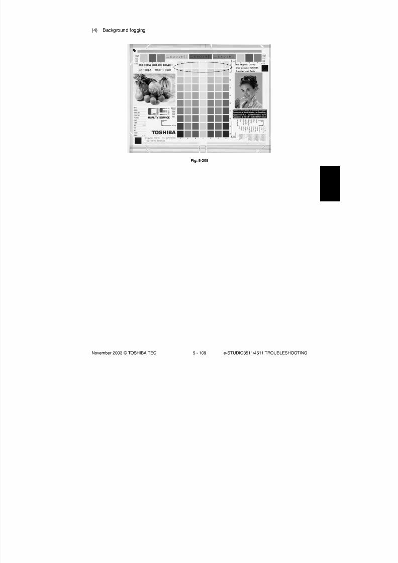
8/2/2019 ES-3511 Service Handbook
http://slidepdf.com/reader/full/es-3511-service-handbook 417/543
November 2003 © TOSHIBA TEC 5 - 109 e-STUDIO3511/4511 TROUBLESHOOTING
(4) Background fogging
Fig. 5-205

8/2/2019 ES-3511 Service Handbook
http://slidepdf.com/reader/full/es-3511-service-handbook 418/543
e-STUDIO3511/4511 TROUBLESHOOTING 5 - 110 November 2003 © TOSHIBA TEC
Remarks
See step 6 if
defects occur.
Cause/Section
Density reproduction
Printer section
Scanner
Parameter
adjustment value
Cover
Auto-toner
Main charger output
Developer biasDeveloper unit
Developer material/
Toner/Drum
Drum cleaning blade
Transfer belt cleaning
blade
Toner dusting
Step
1
2
3
4
5
6
7
8
9
1011
12
13
14
15
16
17
18
Check items
Check the gradation reproduction.
Check the printer output image.
Check if the original glass,
mirrors or lens is dirty.
Check the image processing
parameters.
Adjust the image processing
parameters.
Is the cover installed properly?
(Is the drum exposed to the
external light?)
Is the auto-toner sensor normal?
Is the toner supply operating
constantly?
Is the main charger output
normal?
Is the developer bias proper?Is the contact between the drum
and developer material proper?
Using the specified developer
material, toner and drum?
Have the developer material and
drum reached their PM life?
Is the storage environment of the
toner cartridge 35oC or less
without dew?
Is the drum cleaned properly?
Is the transfer belt cleaning blade
contacted and released properly?
Is the transfer belt cleaning blade
in proper contact with the transfer
belt?
Is the toner accumulated on the
seals of the developer unit?
Measures
Perform the forced performing of
image quality closed-loop control
(05-395) and then automatic
gamma adjustment.
Output the test patterns and
check them.
Color: using 04-231 for eachcolor
Black:using 04-113
Clean it.
Check the value of offsetting
adjustment for background
processing (color) and back-
ground peak adjustment for
range correction (black).
While checking the above
encircled image, adjust the
reproduction level by the offset-
ting adjustment for backgroundprocessing (color) and back-
ground peak adjustment for
range correction (black).
Correct it.
Check the operation of auto-
toner sensor and readjust.
Check the motor and circuits.
Check the circuits.
Check the circuits.Check the doctor-to-sleeve gap
and pole position.
Use the specified developer
material, toner and drum.
Replace the developer material
and drum.
Use the toner cartridge stored in
the environment within specifica-
tion.
Check the drum cleaning blade
pressure.
Check if the spring of the transfer
belt cleaner clutch is removed orif any connector is disconnected.
Otherwise replace the clutch.
Check if the blade pressure
spring is installed.
Remove the toner and clean the
seals.
* If the trouble is not solved at the step 1 and the step 2 or followings (excluding the parameter adjustment) are
performed, make sure to perform “Enforced performing of image quality closed-loop control” and then “Automatic
gamma adjustment” after taking a measure.

8/2/2019 ES-3511 Service Handbook
http://slidepdf.com/reader/full/es-3511-service-handbook 419/543
November 2003 © TOSHIBA TEC 5 - 111 e-STUDIO3511/4511 TROUBLESHOOTING
A
B(5) Moire/lack of sharpness
Fig. 5-206

8/2/2019 ES-3511 Service Handbook
http://slidepdf.com/reader/full/es-3511-service-handbook 420/543
e-STUDIO3511/4511 TROUBLESHOOTING 5 - 112 November 2003 © TOSHIBA TEC
Moire
Remarks
When defects occur,
perform the
corresponding
troubleshooting
procedures.
Cause/Section
Density reproduction
Parameter
adjustment value
Printer section
Step
1
2
3
4
Check items
Check the gradation
reproduction.
Check the image
processing parameters.
Adjust the image
processing parameters.
Check the printer output
image.
Measures
Perform the forced performing
of image quality closed-loop
control (05-395) and thenautomatic gamma adjustment.
Check the sharpness adjust-
ment value.
While checking the above
encircled images A and B,
decrease moire by sharpness
adjustment.
Output the test patterns and
check them.
Color: using 04-231 for each
color
Black:using 04-113
Lack of sharpness
RemarksCause/Section
Density reproduction
Parameter
adjustment value
Step
1
2
3
Check items
Check the gradation
reproduction.
Check the image
processing parameters.
Adjust the image process-
ing parameters.
Measures
Perform the forced performing
of image quality closed-loop
control (05-395) and then
automatic gamma adjustment.
Check the sharpness adjust-
ment value.
While checking the above
encircled image A, increase
sharpness by sharpness
adjustment.
* If the trouble is not solved at the step 1 and the step 2 or followings (excluding the parameter adjustment) are
performed, make sure to perform “Enforced performing of image quality closed-loop control” and then “Automatic
gamma adjustment” after taking a measure.

8/2/2019 ES-3511 Service Handbook
http://slidepdf.com/reader/full/es-3511-service-handbook 421/543
November 2003 © TOSHIBA TEC 5 - 113 e-STUDIO3511/4511 TROUBLESHOOTING
(6) Toner offset
Approx.
173 mm
Black solid
Toner offset (Shadow image appears approx. 173 mm behind the high density image.)
F e e d i n g
d i r e c t i o n
Shadow image
Remarks
When defects
occur, perform
the
corresponding
troubleshooting
procedures.
Cause/Section
Fuser unit
Paper
Developer material
Scanner
Image quality control
Density
Printer density
Step
1
2
3
4
5
6
7
8
9
10
11
12
Check items
Is the pressure between the fuser
belt and pressure roller proper?
Is the thermostat in contact?
Is there scratch on the fuser belt
or pressure roller surface?
Has the fuser belt or pressureroller reached its PM life?
Is the fuser roller temperature
proper?
Is the paper type corresponding
to its mode?
Using recommended paper?
Is the specified developer used?
Are the mirrors, original glass or
lens dirty?
Is the control activated?
Is the density too high?
Check the density of printer
output image.
Measures
Check the pressure removal
parts and pressure mechanism.
Establish its contact.
Replace the fuser belt or the
pressure roller.
Replace the fuser belt or thepressure roller.
Check and correct the control
circuit.
Use the proper type of paper or
select the proper mode.
Use the recommended paper.
Use the specified developer and
toner.
Clean them.
Check the image quality control
related codes.
Perform the forced performing of
image quality closed-loop control
(05-395) and then automatic
gamma adjustment.
Output the test patterns and
check them.
Color: using 04-231 for each
color
Black:using 04-113
Fig. 5-207

8/2/2019 ES-3511 Service Handbook
http://slidepdf.com/reader/full/es-3511-service-handbook 422/543
e-STUDIO3511/4511 TROUBLESHOOTING 5 - 114 November 2003 © TOSHIBA TEC
(7) Blurred image
F e e d i n g
d i r e c t i o n
Cause/Section
Scanner
Drum
Ozone exhaust
Step
1
2
3
4
Check items
Is the scanner bedewed?
Is the drum bedewed or dirty?
Is the ozone exhaust fan operating
properly?
Is the ozone filter stained or damaged?
Measures
Clean it.
Wipe the drum with dry cloth.
* Be sure never use alcohol or other
organic solvents because they have
bad effect on the drum.
Check the connection of the connector.
Replace it.
Fig. 5-208
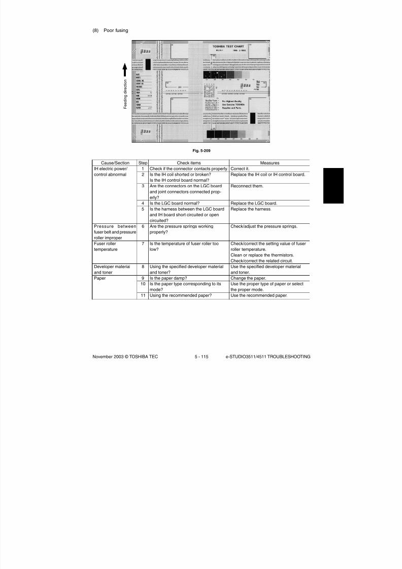
8/2/2019 ES-3511 Service Handbook
http://slidepdf.com/reader/full/es-3511-service-handbook 423/543
November 2003 © TOSHIBA TEC 5 - 115 e-STUDIO3511/4511 TROUBLESHOOTING
(8) Poor fusing
F e e d i n g
d i r e c t i o n
Cause/Section
IH electric power/
control abnormal
Pressure between
fuser belt and pressure
roller improper
Fuser roller
temperature
Developer material
and toner
Paper
Step
1
2
3
4
5
6
7
8
9
10
11
Check items
Check if the connector contacts properly.
Is the IH coil shorted or broken?
Is the IH control board normal?
Are the connectors on the LGC board
and joint connectors connected prop-
erly?
Is the LGC board normal?
Is the harness between the LGC board
and IH board short circuited or opencircuited?
Are the pressure springs working
properly?
Is the temperature of fuser roller too
low?
Using the specified developer material
and toner?
Is the paper damp?
Is the paper type corresponding to itsmode?
Using the recommended paper?
Measures
Correct it.
Replace the IH coil or IH control board.
Reconnect them.
Replace the LGC board.
Replace the harness.
Check/adjust the pressure springs.
Check/correct the setting value of fuser
roller temperature.
Clean or replace the thermistors.
Check/correct the related circuit.
Use the specified developer material
and toner.
Change the paper.
Use the proper type of paper or selectthe proper mode.
Use the recommended paper.
Fig. 5-209

8/2/2019 ES-3511 Service Handbook
http://slidepdf.com/reader/full/es-3511-service-handbook 424/543
e-STUDIO3511/4511 TROUBLESHOOTING 5 - 116 November 2003 © TOSHIBA TEC
(9) Blank print
F e e d i n g
d i r e c t i o n
Fig. 5-210

8/2/2019 ES-3511 Service Handbook
http://slidepdf.com/reader/full/es-3511-service-handbook 425/543
November 2003 © TOSHIBA TEC 5 - 117 e-STUDIO3511/4511 TROUBLESHOOTING
Cause/Section
High-voltage
transformer
(1st/2nd transfer roller
and developer bias)
Developer unit
Drum
Transfer unit
Switching power
supply
Harnesses for SLG,
SYS, LGC and LDR
boards
Laser optical unit
Step
1
2
3
4
5
6
7
8
9
10
11
12
13
14
15
16
Check items
Is the high-voltage transformer output
defective?
Are the connector of the high-voltage
harness securely connected? Is the
harness open circuited?
Is the developer unit installed securely?
Do the developer sleeve and mixer
rotate?
Is the developer material properly
transported?
Is there any magnetic brush phase
error?
Is the doctor sleeve gap incorrect?
Is the drum rotating?
Is the drum grounded?
Is the transfer belt in proper contact with
the drum?
Is the transport of the transfer belt
normal?
Is the releasing movement of the
transfer belt cleaner is normal? (Does
the cleaning blade stay in contact?)
Is the 2nd transfer roller contacted and
released properly?
Is the power supply output (5.1VD)
normal?
Are the connectors securely connected?
Is any harness between the boards open
circuited?
Was the protection seal of slit removed
when replacing the unit?
Measures
Adjust the output and correct the circuit,
or replace the transformer.
Reconnect the harness securely.
Replace the high-voltage harness.
Check/correct the developer sleeve
coupling engaging.
Check/correct the developer drive
system.
Remove foreign matter from the devel-
oper material, if any.
Check the developer pole position.
Adjust the gap with the doctor-sleeve
jig.Check that the drum shaft is inserted.
Check the drum drive system.
Check the contact of the grounding
plate.
Check if the contact releasing lever is at
releasing position. Check the installation
of the transfer belt.
Check the installation of the transfer belt
or transport mechanism.
Check the installation of the transfer belt
cleaning blade. Check the operation of
the transfer belt cleaner clutch.
Check the connection of the connector
of 2nd transfer roller contact clutch and
open circuit of harness.
Replace the switching power supply.
Reconnect the connectors securely.
Replace the harness.
Remove the protection seal.

8/2/2019 ES-3511 Service Handbook
http://slidepdf.com/reader/full/es-3511-service-handbook 426/543
e-STUDIO3511/4511 TROUBLESHOOTING 5 - 118 November 2003 © TOSHIBA TEC
(10) Solid print
F e e d i n g
d i r e c t i o n
Cause/Section
Exposure lamp
Inverter
Main charger
High-voltage
transformer
(main charger wire/ grid bias)
Harnesses for SLG,
SYS and LGC boards
Scanner
Bedewing of scanner
and drum
Step
1
2
3
4
5
6
7
8
Check items
Does the exposure lamp light?
Is the main charger securely installed?
Is the main charger wire open circuited?
Is the high-voltage transformer output
defective?
Are the connector of the high-voltage
harness securely connected? Is the
harness open circuited?
Are the connectors securely connected?
Is any harness between the boards open
circuited ?
Is there foreign matter in the optical
path?
Is the scanner or the drum bedewed?
Measures
Check the contact of the inverter
connector.
If the inverter does not work, replace it.
If the lamp does not work, replace it.
Reinstall it securely.
Replace it.
Adjust the output and correct the circuit,
or replace the high-voltage transformer.
Reconnect the harness securely.
Replace the high-voltage harness.
Reconnect the connectors securely.
Replace the harness.
Remove it.
Clean the mirrors, lens and drum.
Keep the power cord plugged so that the
damp heater can work.
Fig. 5-211

8/2/2019 ES-3511 Service Handbook
http://slidepdf.com/reader/full/es-3511-service-handbook 427/543
November 2003 © TOSHIBA TEC 5 - 119 e-STUDIO3511/4511 TROUBLESHOOTING
(11) White banding (in feeding direction)
F e e d i n g
d i r e c t i o n
Cause/Section
Laser optical unit
Main charger grid
Developer unit
Drum
Transfer unit
Transport path
Discharge lamp
Scanner
Step
1
2
3
4
5
6
7
8
9
10
11
12
13
14
Check items
Is there foreign matter or dust on the slit
glass?
Is there foreign matter on the charger
grid?
Is there foreign matter inside the doctor
blade?
Is there foreign matter on the drum
seal?
Is the drum seal of developer unit inproper contact with the drum?
Is there scratch or foreign matter on the
drum surface?
Is there scratch or foreign matter on the
transfer belt surface?
Are the harness or foreign matters in
contact with the transfer belt surface?
Is the transfer belt cleaning blade
contacted and released properly?
Is the transfer belt cleaning blade in
proper contact with the transfer belt?
Is there any scratch or hole on the 1st/
2nd transfer roller?
Does the toner image touch foreign
matter after transfer, before entering the
fuser unit?
Has any LED of discharge lamp gone
out?
Is there foreign matter or dust in the
optical path?
Measures
Clean the slit glass.
Remove foreign matter.
Remove foreign matter.
Remove foreign matter.
Modify the position of drum seal orreplace it.
Replace the drum.
Replace the transfer belt.
Correct or remove them.
Check if the spring of the transfer belt
cleaner clutch is removed or if any
connector is disconnected. Otherwise
replace the clutch.
Check if the blade pressure spring is
installed.
Replace the 1st/2nd transfer roller.
Remove foreign matter.
Replace the discharge lamp.
Clean the lens and mirrors.
Fig. 5-212

8/2/2019 ES-3511 Service Handbook
http://slidepdf.com/reader/full/es-3511-service-handbook 428/543
e-STUDIO3511/4511 TROUBLESHOOTING 5 - 120 November 2003 © TOSHIBA TEC
(12) White banding (at right angles to feeding direction)
F e e d i n g
d i r e c t i o n
Cause/Section
Main charger
Drum
Discharge lamp
Developer unit
Drive systems
High-voltage
transformer
(main charger wire/
grid, 1st/2nd transfer
roller and developer
bias)
Step
1
2
3
4
5
6
7
8
9
Check items
Is there foreign matter on the charger?
Is the terminal contact poor?
Is there any abnormalities on the drum
surface?
Is the drum grounded?
Is the discharge lamp lighting properly?
Is the developer sleeve rotating cor-rectly? Is there any abnormalities on the
sleeve surface?
Is the connection of developer bias
supply terminal normal?
Is the drum, scanner or transfer belt
jittery?
Is the high-voltage transformer output
defective?
Measures
Remove foreign matter.
Clean or adjust the terminals.
Replace the drum.
Check the contact of the grounding
plate.
Replace the discharge lamp or clean
terminals.
Check the developer drive system, orclean the sleeve surface.
Correct it.
Check each drive system.
Check/correct any electric leakage and
related circuits.
If the high-voltage transformer does not
work, replace it.
Fig. 5-213

8/2/2019 ES-3511 Service Handbook
http://slidepdf.com/reader/full/es-3511-service-handbook 429/543
November 2003 © TOSHIBA TEC 5 - 121 e-STUDIO3511/4511 TROUBLESHOOTING
(13) Skew (slantwise copying)
F e e d i n g
d i r e c t i o n
Cause/Section
Drawer/LCF
Paper feed roller
Rollers
Aligning amount
Registration roller
Pre-registration guide
2nd transfer front
guide
RADF
Step
1
2
3
4
5
6
7
8
9
10
11
Check items
Is the drawer or LCF properly installed?
Is too much paper loaded in the drawer
or LCF?
Is the paper corner folded?
Are the drawer or LCF side guides
properly set?
Is the surface of paper feed roller dirty?
Is each roller improperly fixed to theshaft?
Is the aligning amount proper?
Is the registration roller spring removed?
Is the pre-registration guide improperly
installed?
Is the 2nd transfer front guide installed
properly?
Is the RADF installed and adjusted
properly?
Measures
Reinstall the drawer or LCF properly.
Reduce paper to 550 sheets or less.
(2500 sheets or less/stack for LCF)
Change the paper direction and reinsert it.
Adjust the side guides.
Clean the roller surface with alcohol, or
replace the roller.
Check and reinstall E-rings, pins, clipsand setscrews.
Increase the aligning amount.
Mount the spring correctly. Clean the
roller if it is dirty.
Correct it.
Correct it.
Reinstall and readjust it.
Fig. 5-214
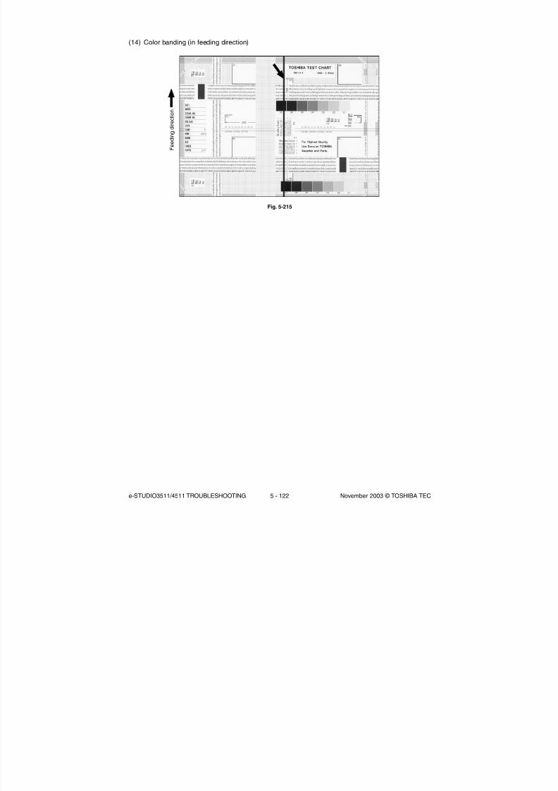
8/2/2019 ES-3511 Service Handbook
http://slidepdf.com/reader/full/es-3511-service-handbook 430/543
e-STUDIO3511/4511 TROUBLESHOOTING 5 - 122 November 2003 © TOSHIBA TEC
(14) Color banding (in feeding direction)
F e e d i n g
d i r e c t i o n
Fig. 5-215

8/2/2019 ES-3511 Service Handbook
http://slidepdf.com/reader/full/es-3511-service-handbook 431/543
November 2003 © TOSHIBA TEC 5 - 123 e-STUDIO3511/4511 TROUBLESHOOTING
Cause/Section
Scanner
Main charger
Cleaner
Transfer unit
Fuser unit
Drum
Laser optical unit
Step
1
2
3
4
5
6
7
8
9
10
11
12
13
14
15
16
17
18
19
Check items
Is there foreign matter in the optical
path?
Is there dust or stain on the shading
correction plate or ADF original glass?
Is there foreign matter on the charger
grid?
Is the charger grid dirty or deformed?
Is there foreign matter on the main
charger?
Is the charger wire dirty or deformed?
Is there foreign matter inside the
charger case?
Is the inner surface of charger case
dirty?
Are the pads of charger wire cleaner
stopping at the position other than their
home position?Is there paper dust on the cleaning
blade edge?
Is the cleaning blade contact improper?
Is toner recovery defective?
Are the harness or foreign matters in
contact with the transfer belt surface?
Is there paper dust on the edge of
transfer belt cleaning blade?
Is the transfer belt cleaning blade
contacted and released properly?
Is the transfer belt cleaning blade in
proper contact with the transfer belt?
a. Is there dirt or scratches on the fuser
belt and pressure roller surface?
b. Is the thermistor dirty?
Are there scratches on the drum
surface?
Is there foreign matter or dust on the slit
glass?
Measures
Clean the slit, lens and mirrors.
Clean it.
Remove foreign matter.
Clean or replace the charger grid.
Remove foreign matter.
Clean or replace the charger wire.
Remove foreign matter.
Clean inside.
Correct the position.
Clean or replace the paper dust removal
brush for the registration roller.
Clean or replace the cleaning blade.
Correct it.
Clean the toner recovery auger section.
Correct or remove them.
Clean or replace it.
Check if the spring of the transfer belt
cleaner clutch is removed or if any
connector is disconnected. Otherwise
replace the clutch.
Check if the blade pressure spring is
installed.
a.Clean or replace them.
b.Clean the thermistor.
Replace the drum.
Remove foreign matter or dust.

8/2/2019 ES-3511 Service Handbook
http://slidepdf.com/reader/full/es-3511-service-handbook 432/543
e-STUDIO3511/4511 TROUBLESHOOTING 5 - 124 November 2003 © TOSHIBA TEC
(15) Color banding (at right angles to feeding direction)
F e e d i n g
d i r e c t i o n
Cause/Section
Main charger
Fuser unit
High-voltage
transformer
(main charger wire/grid
and transfer roller bias)
Drum
2nd transfer roller
Scanner
Step
1
2
3
4
5
6
7
8
9
Check items
Is the charger wire dirty or deformed?
Is the fuser belt, pressure roller or oil
roller dirty?
Is the high-voltage transformer output
defective?
Is each joint of high-voltage output
loosened? (Check if any electric leakageis causing noise.)
Is there deep scratch on the drum
surface?
Are there fine scratches on the drum
surface (drum pitting)?
Is the drum grounded?
Is the 2nd transfer roller rotating
normally?
Is there foreign matter on the carriage
rail?
Measures
Clean or replace the charger wire.
Clean them.
Check the circuit and replace the high-
voltage transformer if not working.
Reconnect each joint.
Replace the drum, especially if the
scratch has reached the aluminum
base.
Check and correct the contact of
cleaning blade and recovery blade.
Check the contact of the grounding
plate.
Clean the roller area or replace the
roller.
Remove foreign matter.
Fig. 5-216

8/2/2019 ES-3511 Service Handbook
http://slidepdf.com/reader/full/es-3511-service-handbook 433/543
November 2003 © TOSHIBA TEC 5 - 125 e-STUDIO3511/4511 TROUBLESHOOTING
(16) White spots
F e e d i n g
d i r e c t i o n
Cause/Section
Developer unit/Toner
cartridge
Developer material/
Toner/Drum
Transfer unit
Main charger
High-voltage
transformer
(main charger wire/
grid, developer 1st/
2nd transfer roller
bias)
Paper
Step
1
2
3
4
5
6
7
8
9
10
1112
13
14
Check items
Is the toner density of developer material
proper?
Is the doctor-sleeve gap proper?
Using the specified developer material,
toner and drum?
Have the developer material and drum
reached their PM life?Is the storage environment of the toner
cartridge 35oC or less without dew?
Is there any dent on the surface of the
drum?
Is there any film forming on the drum?
Is the drum bedewed?
Is there foreign matter on the transfer
belt surface?
Is there foreign matter on the transfer
belt drive roller?
Is there foreign matter on the charger?Is the charger wire dirty or deformed?
Is the high-voltage transformer output
defective?
Is the paper type corresponding to its
mode?
Measures
Check and correct the auto-toner sensor
and toner supply operation.
Check if the amount of toner is sufficient
in the toner cartridge.
Adjust the gap.
Use the specified developer material,
toner and drum.
Replace the developer material and
drum.Use the toner cartridge stored in the
environment within specification.
Replace the drum.
Clean or replace the drum.
Wipe the drum surface with a piece of
dry cloth.
Remove foreign matter.
Clean the transfer belt unit.
Remove it.Clean or replace the charger wire.
Adjust the output.
Use the proper type of paper or select
the proper mode.
Fig. 5-217

8/2/2019 ES-3511 Service Handbook
http://slidepdf.com/reader/full/es-3511-service-handbook 434/543
e-STUDIO3511/4511 TROUBLESHOOTING 5 - 126 November 2003 © TOSHIBA TEC
(17) Poor transfer
F e e d i n g
d i r e c t i o n
Cause/Section
Transfer unit
Paper
Registration roller
High-voltage
transformer
(1st/2nd transfer
roller bias)
Step
1
2
3
4
5
6
7
8
9
Check items
Is the transfer belt or 1st/2nd transfer
rollers dirty?
Is the transfer belt in proper contact with
the drum ?
Is the 2nd transfer roller in proper
contact with the transfer belt?
Is there any deformation or abnormali-
ties on the transfer belt?
Is paper in the drawer or LCF curled?
Is paper in the drawer or LCF damp?
Is the registration roller malfunctioning?
Is the high-voltage transformer output
defective?
Are the high-voltage harness and
terminals in proper contact?
Measures
Clean it.
Correct it.
Correct it.
Replace the belt.
Reinsert paper with reverse side up orchange paper.
Change paper.
* Avoid storing paper in damp place.
Clean the roller, remount the spring, or
replace defective clutch-related parts.
Check the circuit and adjust the trans-
former output.
Correct them if loosened.
Fig. 5-218

8/2/2019 ES-3511 Service Handbook
http://slidepdf.com/reader/full/es-3511-service-handbook 435/543
November 2003 © TOSHIBA TEC 5 - 127 e-STUDIO3511/4511 TROUBLESHOOTING
(18) Uneven image density
F e e d i n g
d i r e c t i o n
Cause/Section
Main charger
Transfer unit
Laser optical unit
Discharge lamp
Developer unit
Scanner section
Step
1
2
3
4
5
6
7
8
9
10
11
12
Check items
Is the main charger dirty?
Is the transfer belt or 1st/2nd transfer
rollers dirty?
Is the transfer belt in proper contact with
the drum?
Is 2nd transfer roller in proper contact
with the transfer belt?
(Is the roller tilted?)
Is there any abnormalities or deforma-tion on the transfer belt?
Is there foreign matter or dust on the slit
glass?
Is the discharge lamp dirty?
Has any LED of discharge lamp gone
out?
Is the magnetic brush in proper contact
with the drum?
Is the developer unit pressure mecha-
nism malfunctioning?
Is the transport of developer material
poor?a.Is the platen cover or RADF open?
b.Is the original glass, mirrors, or lens
dirty?
Measures
Clean it or replace the charger wire.
Clean the belt.
Correct it.
Correct it.
Replace the transfer belt.
Clean the slit glass.
Clean it.
Replace it.
Adjust the doctor-sleeve gap.
Check the mechanism.
Remove foreign matter if any.
a.Close the platen cover or RADF.
b.Clean them.
Fig. 5-219

8/2/2019 ES-3511 Service Handbook
http://slidepdf.com/reader/full/es-3511-service-handbook 436/543
e-STUDIO3511/4511 TROUBLESHOOTING 5 - 128 November 2003 © TOSHIBA TEC
(19) Faded image (low density)
F e e d i n g
d i r e c t i o n
Cause/Section
Toner empty
Auto-toner circuit
Toner motor
Toner cartridge
Developer material
Developer unit
Main charger
Drum
Transfer unit
High-voltage
transformer(developer bias)
Step
1
2
3
4
5
6
7
8
9
10
11
12
13
Check items
Is the “ADD TONER” symbol blinking?
Is there enough toner in the cartridge?
Is the toner density of developer
material too low?
Is the toner motor malfunctioning?
Are there any abnormalities in the toner
cartridge?
Has the developer material reached itsPM life?
Is the magnetic brush in proper contact
with the drum?
Is the main charger dirty?
Is there film forming on the drum
surface?
Has the drum reached its PM life?
Has the transfer belt, 1st or 2nd transfer
roller reached its PM life?
Is the high-voltage transformer output
settings improper?Are the connector of the high-voltage
harness securely connected? Is the
harness open circuited?
Measures
Replace the toner cartridge.
Check the auto-toner circuit function.
Check the motor drive circuit.
Replace the toner cartridge.
Replace developer material.
Check the developer unit installation.
Check the doctor-sleeve gap and pole
position.
Clean it or replace the charger wire.
Clean or replace the drum.
Replace the drum.
Replace the transfer belt, 1st or 2nd
transfer roller.
Adjust the high-voltage transformer
output.Reconnect the harness securely.
Replace the high-voltage harness.
Fig. 5-220

8/2/2019 ES-3511 Service Handbook
http://slidepdf.com/reader/full/es-3511-service-handbook 437/543
November 2003 © TOSHIBA TEC 5 - 129 e-STUDIO3511/4511 TROUBLESHOOTING
(20) Image dislocation in feeding direction
F e e d i n g
d i r e c t i o n
Cause/Section
Adjustment error of
scanner or printer
section
Registration roller
Paper feed clutch
Pre-registration guide
Transfer belt
Step
1
2
3
4
5
6
7
8
Check items
Is same dislocation on every copy?
Is the registration roller dir ty, or is the
spring removed?
Is the registration motor malfunctioning?
Is the registration roller clutch operating
normally? (Is the timing of operationdelaying?)
Is the paper feed clutch malfunctioning?
Is the pre-registration guide improperly
installed?
Is there any stain or scratch on the
reflection tape?
Is the lens of the transfer belt home
position sensor stained?
Measures
Adjust the scanner/printer using the
Adjustment Mode.
Clean the roller with alcohol.
Reinstall the spring.
Adjust or replace the gears, etc. if they
are not engaged properly.
Replace the registration roller clutch.
Check the circuit or the clutch and
replace them if necessary.
Reinstall the guide.
Clean or replace it.
Clean or replace it.
Fig. 5-221

8/2/2019 ES-3511 Service Handbook
http://slidepdf.com/reader/full/es-3511-service-handbook 438/543
e-STUDIO3511/4511 TROUBLESHOOTING 5 - 130 November 2003 © TOSHIBA TEC
(21) Image jittering
F e e d i n g
d i r e c t i o n
Cause/Section
—
Registration roller
Transfer unit
Fuser unit
Drum
Scanner
Drum drive system
Step
1
2
3
4
5
6
7
8
9
10
11
Check items
Is the toner image on the drum proper?
Is the registration roller rotating normally?
Is the transfer belt or 2nd transfer roller
operating normally?
Are the fuser roller and pressure roller
rotation proper?Is the fuser belt transportation proper?
Is there large scratch on the drum?
Is the slide sheet defective?
Are there any abnormalities on the
carriage feet?
Is the tension of timing belt
inappropriate?
Is the carriage drive system
malfunctioning?
Are any mirrors loosely installed?
Is the drum drive system malfunctioning?
Measures
If proper, perform step 1 to 3; otherwise
perform step 4 and after.
Check the registration roller section and
its springs.
Check the drive system and replace the
transfer belt or 2nd transfer roller if
necessary.
Check the drive system.
Replace the fuser belt, fuser roller andpressure roller if necessary.
Replace the drum.
Replace it.
Replace the feet.
Correct the tension.
Check the carriage drive system.
Install them properly.
Check the drum drive system.
Clean or replace the belts, pulleys,bushings if they have dirt or scratches.
Fig. 5-222

8/2/2019 ES-3511 Service Handbook
http://slidepdf.com/reader/full/es-3511-service-handbook 439/543
November 2003 © TOSHIBA TEC 5 - 131 e-STUDIO3511/4511 TROUBLESHOOTING
(22) Poor cleaning
F e e d i n g
d i r e c t i o n
Note: Poor cleaning may occur in feeding direction.
Fig. 5-223
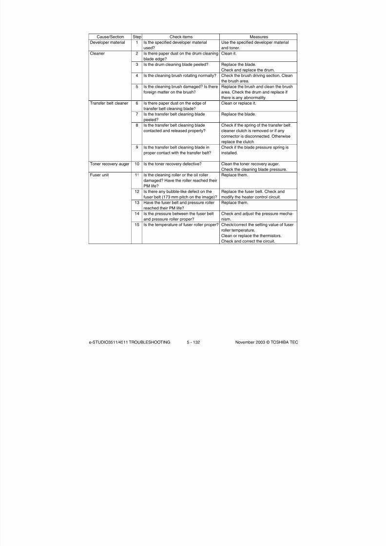
8/2/2019 ES-3511 Service Handbook
http://slidepdf.com/reader/full/es-3511-service-handbook 440/543
e-STUDIO3511/4511 TROUBLESHOOTING 5 - 132 November 2003 © TOSHIBA TEC
Cause/Section
Developer material
Cleaner
Transfer belt cleaner
Toner recovery auger
Fuser unit
Step
1
2
3
4
5
6
7
8
9
10
11
12
13
14
15
Check items
Is the specified developer material
used?
Is there paper dust on the drum cleaning
blade edge?
Is the drum cleaning blade peeled?
Is the cleaning brush rotating normally?
Is the cleaning brush damaged? Is there
foreign matter on the brush?
Is there paper dust on the edge of
transfer belt cleaning blade?
Is the transfer belt cleaning blade
peeled?
Is the transfer belt cleaning blade
contacted and released properly?
Is the transfer belt cleaning blade in
proper contact with the transfer belt?
Is the toner recovery defective?
Is the cleaning roller or the oil roller
damaged? Have the roller reached their
PM life?
Is there any bubble-like defect on the
fuser belt (173 mm pitch on the image)?
Have the fuser belt and pressure roller
reached their PM life?
Is the pressure between the fuser belt
and pressure roller proper?
Is the temperature of fuser roller proper?
Measures
Use the specified developer material
and toner.
Clean it.
Replace the blade.
Check and replace the drum.
Check the brush driving section. Clean
the brush area.
Replace the brush and clean the brush
area. Check the drum and replace if
there is any abnormality.
Clean or replace it.
Replace the blade.
Check if the spring of the transfer belt
cleaner clutch is removed or if any
connector is disconnected. Otherwisereplace the clutch.
Check if the blade pressure spring is
installed.
Clean the toner recovery auger.
Check the cleaning blade pressure.
Replace them.
Replace the fuser belt. Check and
modify the heater control circuit.
Replace them.
Check and adjust the pressure mecha-
nism.
Check/correct the setting value of fuser
roller temperature.
Clean or replace the thermistors.
Check and correct the circuit.

8/2/2019 ES-3511 Service Handbook
http://slidepdf.com/reader/full/es-3511-service-handbook 441/543
November 2003 © TOSHIBA TEC 5 - 133 e-STUDIO3511/4511 TROUBLESHOOTING
(23) Uneven light distribution
F e e d i n g
d i r e c t i o n
Cause/Section
Original glass
Main charger
Discharge lamp
Scanner
Exposure lamp
Step
1
2
3
4
5
6
Check items
Is the original glass dirty?
Are the main charger wire, grid and case
dirty?
Is the discharge lamp dirty?
Are the reflector, exposure lamp,
mirrors, lens, etc. dirty?
Is the exposure lamp tilted?
Is the lamp discolored or degraded?
Measures
Clean the glass.
Clean or replace them.
Clean it.
Clean them.
Adjust the installed position of the lamp.
Replace it.
Fig. 5-224

8/2/2019 ES-3511 Service Handbook
http://slidepdf.com/reader/full/es-3511-service-handbook 442/543
e-STUDIO3511/4511 TROUBLESHOOTING 5 - 134 November 2003 © TOSHIBA TEC
(24) Blotched image
F e e d i n g
d i r e c t i o n
Cause/Section
Paper
Transfer unit
High-voltage
transformer
(1st/2nd transfer
roller bias)
Step
1
2
3
4
5
6
Check items
Is the paper type corresponding to its
mode?
Is paper too dry?
Is the transfer belt in proper contact with
the drum?
Is the 2nd transfer roller in proper
contact with the transfer belt?
Are there any abnormalities on the
transfer belt?Is the high-voltage transformer output
abnormal?
Measures
Check the paper type and mode.
Change paper.
Correct it.
Correct it.
Clean or replace the transfer belt.
Adjust the output. Replace the trans-
former, if necessary.
Fig. 5-225

8/2/2019 ES-3511 Service Handbook
http://slidepdf.com/reader/full/es-3511-service-handbook 443/543
November 2003 © TOSHIBA TEC 5 - 135 e-STUDIO3511/4511 TROUBLESHOOTING
(25) Stain on the paper back side
F e e d i n g
d i r e c t i o n
Fig. 5-226
F e e d i n g
d i r e c t i o n
The edge of image
cut off.
Printing side of 1st page
Back side of 2nd page
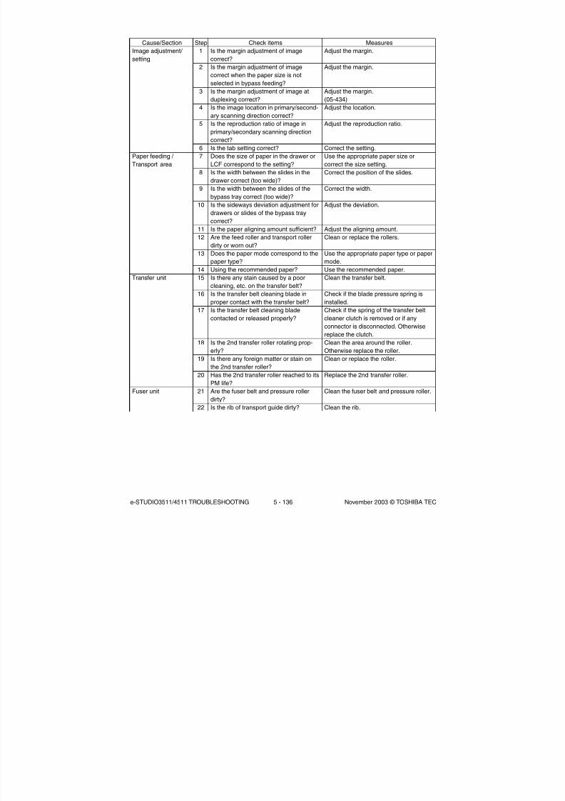
8/2/2019 ES-3511 Service Handbook
http://slidepdf.com/reader/full/es-3511-service-handbook 444/543
e-STUDIO3511/4511 TROUBLESHOOTING 5 - 136 November 2003 © TOSHIBA TEC
Cause/Section
Image adjustment/
setting
Paper feeding /
Transport area
Transfer unit
Fuser unit
Step
1
2
3
4
5
6
7
8
9
10
11
12
13
14
15
16
17
18
19
20
21
22
Check items
Is the margin adjustment of image
correct?
Is the margin adjustment of image
correct when the paper size is not
selected in bypass feeding?
Is the margin adjustment of image at
duplexing correct?Is the image location in primary/second-
ary scanning direction correct?
Is the reproduction ratio of image in
primary/secondary scanning direction
correct?
Is the tab setting correct?
Does the size of paper in the drawer or
LCF correspond to the setting?
Is the width between the slides in the
drawer correct (too wide)?
Is the width between the slides of the
bypass tray correct (too wide)?
Is the sideways deviation adjustment for
drawers or slides of the bypass tray
correct?
Is the paper aligning amount sufficient?
Are the feed roller and transport roller
dirty or worn out?
Does the paper mode correspond to the
paper type?
Using the recommended paper?
Is there any stain caused by a poor
cleaning, etc. on the transfer belt?
Is the transfer belt cleaning blade in
proper contact with the transfer belt?Is the transfer belt cleaning blade
contacted or released properly?
Is the 2nd transfer roller rotating prop-
erly?
Is there any foreign matter or stain on
the 2nd transfer roller?
Has the 2nd transfer roller reached to its
PM life?
Are the fuser belt and pressure roller
dirty?Is the rib of transport guide dirty?
Measures
Adjust the margin.
Adjust the margin.
Adjust the margin.
(05-434)Adjust the location.
Adjust the reproduction ratio.
Correct the setting.
Use the appropriate paper size or
correct the size setting.
Correct the position of the slides.
Correct the width.
Adjust the deviation.
Adjust the aligning amount.
Clean or replace the rollers.
Use the appropriate paper type or paper
mode.
Use the recommended paper.
Clean the transfer belt.
Check if the blade pressure spring is
installed.Check if the spring of the transfer belt
cleaner clutch is removed or if any
connector is disconnected. Otherwise
replace the clutch.
Clean the area around the roller.
Otherwise replace the roller.
Clean or replace the roller.
Replace the 2nd transfer roller.
Clean the fuser belt and pressure roller.
Clean the rib.

8/2/2019 ES-3511 Service Handbook
http://slidepdf.com/reader/full/es-3511-service-handbook 445/543
November 2003 © TOSHIBA TEC 5 - 137 e-STUDIO3511/4511 TROUBLESHOOTING04/09
5.3 Replacement of PC Boards and HDD
<CAUTION IN REPLACING PC BOARDS>
The ID for each equipment is registered on the LGC board, the DRV board, the SYS board and the
SLG board. So, if their replacement is required, be sure to replace only one board at a time
If more than one of the LGC board, the DRV board and the SYS board require replacement, replace
them in the following procedure.
1. First, replace one of the board to be replaced.
2. Turn the power ON and confirm that "READY" is displayed.
3. Turn the power OFF.
4. Replace another board that requires replacement.
5. Repeat steps 2 to 4.
The LGC board and DRV board can be replaced without other settings.
When the HDD requires replacement, see “5.3.1 Replacing HDD”.
When the SYS board requires replacement, see “5.3.2 Replacing SYS board”.
When the SLG board requires replacement, see “5.3.3 Replacing SLG board”.
When NVRAM requires replacement or clearing, see “5.3.4 NVRAM replacing and clearing”.
5.3.1 Replacing HDD
<CAUTION IN REPLACING HDD>
When the HDD is replaced, it is necessary to back up the data in the HDD before replacing and to
recover them after replacing.
Notes:
1. To maintain the security, ask users to perform the backup/restore for users’ data/information in the
HDD. The service technician can perform them only when users permit it.
2. Some data in the HDD cannot be backed up and can be kept only on the paper.
The procedure for replacing the HDD is as follows.
(1) Ask users to back up the data in the HDD. See the following for the item of data, and the
possibility and the measure of the backup.
1) Image data in the Electronic Filing
- Archive them in the “e-Filing” of TopAccess.
2) F-code information, Template registration information, Address book
- Back them up in the “Administrator” menu of TopAccess.
3) Department management data
- Export them in “Administrator” menu of TopAccess.
4) Log data (Print, Scan, FAX (Transmission/Reception))
- Export them in the “Administrator” menu of TopAccess. (Import cannot be performed.)
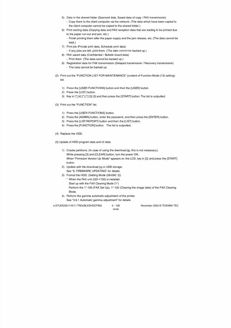
8/2/2019 ES-3511 Service Handbook
http://slidepdf.com/reader/full/es-3511-service-handbook 446/543
e-STUDIO3511/4511 TROUBLESHOOTING 5 - 138 November 2003 © TOSHIBA TEC04/09
5) Data in the shared folder (Scanned data, Saved data of copy / FAX transmission)
- Copy them to the client computer via the network. (The data which have been copied to
the client computer cannot be copied to the shared folder.)
6) Print waiting data (Copying data and FAX reception data that are waiting to be printed due
to the paper run-out and jam, etc.)
- Finish printing them after the paper supply and the jam release, etc. (The data cannot be
kept.)
7) Print job (Private print data, Schedule print data)
- If any jobs are left, print them. (The data cannot be backed up.)
8) FAX saved data (Confidential / Bulletin board data)
- Print them. (The data cannot be backed up.)
9) Registration data for FAX transmission (Delayed transmission / Recovery transmission)
- The data cannot be backed up.
(2) Print out the “FUNCTION LIST FOR MAINTENANCE” (content of Function Mode (13) setting)
list.
1) Press the [USER FUNCTIONS] button and then the [USER] button.
2) Press the [LIST] button.
3) Key in [*] [#] [*] [*] [3] [3] and then press the [START] button. The list is outputted.
(3) Print out the “FUNCTION” list.
1) Press the [USER FUNCTIONS] button.
2) Press the [ADMIN] button, enter the password, and then press the [ENTER] button.
3) Press the [LIST/REPORT] button and then the [LIST] button.
4) Press the [FUNCTION] button. The list is outputted.
(4) Replace the HDD.
(5) Update of HDD program data and UI data.
1) Create partitions. (In case of using the download jig, this is not necessary.)
While pressing [3] and [CLEAR] button, turn the power ON.
When “Firmware Version Up Mode” appears on the LCD, key in [3] and press the [START]
button.
2) Update with the download jig or USB storage.
See “6. FIRMWARE UPDATING” for details.
3) Format the HDD. (Setting Mode (08-690: 2))
* When the FAX unit (GD-1150) is installed.
Start up with the FAX Clearing Mode (1*)
Perform the 1*-100 (FAX Set Up), 1*-102 (Clearing the image data) of the FAX Clearing
Mode.
4) Perform the gamma automatic adjustment of the printer.
See “3.6.1 Automatic gamma adjustment” for details.

8/2/2019 ES-3511 Service Handbook
http://slidepdf.com/reader/full/es-3511-service-handbook 447/543
November 2003 © TOSHIBA TEC 5 - 139 e-STUDIO3511/4511 TROUBLESHOOTING04/09
(6) Ask users to reset the user’s setting items and to restore the data/information. See the following
for the reset and the restore.
1) Printer driver
- Upload them in the “Administrator” menu of TopAccess.
2) F-code information, Template registering information, Address book
- Restore them in the “Administrator” menu of TopAccess
3) Department management data
- Import them in the “Administrator” menu of TopAccess.
4) Image data in the Electronic Filing
- Upload them in the “e-Filing” of TopAccess.
(7) Referring to the “FUNCTION LIST FOR MAINTENANCE” list which was printed beforehand,
perform the re-setting.
1) Print out the “FUNCTION LIST FOR MAINTENANCE” list after the formatting. (Refer to the
procedure of (2).)
2) While pressing [1] and [3] simultaneously, turn the power ON. (Function Mode)
3) Compare the lists which were printed before and after the formatting to check the setting
items having the different setting values. Set the value which was set before the formatting.
4) Turn the power OFF.
(8) Referring to the “FUNCTION” list which was printed beforehand, perform the re-setting of the
default setting of the FAX function.
1) Press the [USER FUNCTIONS] button.
2) Press the [ADMIN] button, enter the password, and then press the [ENTER] button.
3) Press the [FAX] button and then the [TERMINAL ID] button to set each item.
4) Press the [INITIAL SETUP] button to set each item.
5.3.2 Replacing SYS board
<<CAUTION IN REPLACING the SYS board>>
The procedure for replacing the SYS board is as follows.
<After replacing the SYS board>
(1) Install DIMM (main memory) to the new SYS board (from the old SYS board).
(2) Install NVRAM to the new SYS board (from the old SYS board).
(3) Install NIC board to the new SYS board (from the old SYS board).

8/2/2019 ES-3511 Service Handbook
http://slidepdf.com/reader/full/es-3511-service-handbook 448/543
e-STUDIO3511/4511 TROUBLESHOOTING 5 - 140 November 2003 © TOSHIBA TEC
(4) Update the version of system ROMs (System Firmware, OS data, UI data) (The ROMs had been
used for the old SYS board).
* See “6. FIRMWARE UPDATING” for the details of System ROM update.
(5) Turn the power OFF and start up with the Setting Mode (08).
(6) When the message “SRAM ERROR DOES IT INITIALIZE?” is displayed on the LCD, press the
[INITIALIZE] button.
* SRAM is cleared
* If SRAM is not performed, F090 error occurs when starting up.
Notes:
• When SRAM is cleared, following items need to be re-set, so make sure the contents of
settings are kept as a record.
<FAX settings>
Terminal IDDefault setting of fax
<E-mail settings>
Setting of properties for E-mail message
<Internet Fax>
Setting of properties for Internet Fax
• When SRAM is cleared, the toner cartridge consumed count of Automatic ordering function of
supplies becomes 0, however, it cannot be re-set.
(7) [If a scrambler board has already been installed]Perform 08-698 (Entering the key code for scrambler board). Have the user enter the key code.
(8) Perform 08-200 (date and time setting) to set Date/Time.
(9) Turn the power OFF.
* If the FAX board has not been installed, skip to step (13).
(10)Start up with the FAX Clearing Mode (1*)
(11)Perform 1*-102 (Clearing the image data).
Note:
Following image data are deleted when 1*-102 is performed.
- Images of fax polling transmission
- Images of fax Mailbox and box information
- Images of fax transmission
- Images of fax reception
04/09

8/2/2019 ES-3511 Service Handbook
http://slidepdf.com/reader/full/es-3511-service-handbook 449/543
November 2003 © TOSHIBA TEC 5 - 141 e-STUDIO3511/4511 TROUBLESHOOTING04/09
(12)Turn the power OFF.
(13)Turn the power ON.
(14)Set the dial type. [USER FUNCTIONS]→ [ADMIN]→ [FAX]→ [INITIAL SETUP]
5.3.3 Replacing SLG board
<CAUTION IN REPLACING SLG BOARD>
When the SLG board has been replaced, “Data transfer of characteristic value of scanner / SYS board
→ SLG board (05-363)” must be performed.
5.3.4 NVRAM replacing and clearing
<CAUTION IN REPLACING AND CLEARING NVRAM>
When NVRAM has been replaced or cleared (”System all clearing (08-669)”), the following adjustments
must be performed.
1. Perform “Data transfer of characteristic value of scanner / SLG board→ SYS board (05-364)”.
2. Perform “Image quality control initialization (05-396)” ( Chapter 3.3), and then perform
“Automatic gamma adjustment (05-1642, 1000 and 1002)” consecutively ( Chapters 3.5.1
and 3.6.1).

8/2/2019 ES-3511 Service Handbook
http://slidepdf.com/reader/full/es-3511-service-handbook 450/543
e-STUDIO3511/4511 TROUBLESHOOTING 5 - 142 November 2003 © TOSHIBA TEC

8/2/2019 ES-3511 Service Handbook
http://slidepdf.com/reader/full/es-3511-service-handbook 451/543
November 2003 © TOSHIBA TEC 6 - 1 e-STUDIO3511/4511 FIRMWARE UPDATING
6. FIRMWARE UPDATING
In this equipment, following firmware is written on the ROM on each board.
Firmware
Master data (HDD program data, UI data)
System ROM (System firmware, OS data, UI data)Engine ROM (Machine firmware)
Scanner ROM (Scanner firmware)
NIC ROM (NIC firmware)
RADF ROM (RADF firmware)
Finisher ROM (Finisher firmware)
Finisher ROM (Saddle stitcher firmware)
FAX ROM (FAX firmware)
Stored
Hard disk
System control PC board (SYS board)Logic PC board (LGC board)
Scanning section control PC board (SLG board)
NIC board
RADF control PC board (MR-3015)
Finisher control PC board (MJ-1023/ MJ-1024)
Finisher control PC board (MJ-1024)
FAX board (GD-1150)
When you want to update the firmware above or the equipment becomes inoperative status due to
some defectives of the firmware, updating the firmware is available by the following actions.
Updating with the download jig
6.1 Firmware Updating with Download Jig
• Updating with PC connected
6.2 Firmware Updating with FSMS (Field Service Manager)
• Updating with the USB Storage Device
6.3 Firmware Updating with USB Storage Device
Notes:
• Written firmware varies depending on the kinds of the boards provided as service parts. For updating,
only the minimum firmware is installed on the system control PC board, logic PC board, and scanning
section control PC board. No firmware is installed on the NIC board and FAX board. The latest version
of the firmware at the delivery is written on the RADF control PC board and finisher control PC board.
When any of above boards is replaced with a new one in the field, confirm the other firmware version
used with and then write the suitable version of the firmware.
• The firmware (master data) is not installed on the hard disk provided as a service part. When the hard
disk is replaced with a new one, confirm the other firmware version used with and then write the suitable
version of the firmware.

8/2/2019 ES-3511 Service Handbook
http://slidepdf.com/reader/full/es-3511-service-handbook 452/543
e-STUDIO3511/4511 FIRMWARE UPDATING 6 - 2 November 2003 © TOSHIBA TEC
6.1 Firmware Updating with Download Jig
In this equipment, it is feasible to update the firmware automatically by connecting the download jig
using the dedicated connector and turning ON the equipment.
The download jig consists of the ROM, in which the program is written, and the jig board. And three
types of the download jigs are available for each type of the firmware.
For updating the firmware, in addition to the current ways such as updating each firmware individually,
the batch update of the firmware of the equipment is available (except the hard disk and the option).
Firmware
Master data
System ROM
Engine ROM
Scanner ROM
NIC ROM
RADF ROM
Finisher ROM
(Finisher firmware)
Finisher ROM
(Saddle stitcher
firmware)FAX ROM
Stored
Hard disk
System control PC board
(SYS board)
Logic PC board
(LGC board)
Scanning section controlPC board
(SLG board)
NIC board
RADF control PC board
(MR-3015)
Finisher control PC board
(MJ-1023/MJ-1024)
Finisher control PC board
(MJ-1024)
FAX board (GD-1150)
Individual update
PWA-DWNLD-350-JIG2
(48 MB)
PWA-DWNLD-350-JIG1
(16 MB)
K-PWA-DLM-320
or
PWA-DWNLD-350-JIG1
(16 MB)
K-PWA-DLM-320or
PWA-DWNLD-350-JIG1
(16 MB)
PWA-DWNLD-350-JIG1
(16 MB)
K-PWA-DLM-320
K-PWA-DLM-320
K-PWA-DLM-320
K-PWA-DLM-320
Batch update
—
PWA-DWNLD-350-JIG1
(16 MB)
—
—
—
—
Download jig
Refer to the following for the details to update with each download jig.
6.1.1 PWA-DWNLD-350-JIG2 (48 MB)
6.1.2 PWA-DWNLD-350-JIG1 (16 MB)
6.1.4 K-PWA-DLM-320
04/05

8/2/2019 ES-3511 Service Handbook
http://slidepdf.com/reader/full/es-3511-service-handbook 453/543
November 2003 © TOSHIBA TEC 6 - 3 e-STUDIO3511/4511 FIRMWARE UPDATING
[Jig board: PWA-DWNLD-350-JIG2 (48 MB)] [Jig board: PWA-DWNLD-350-JIG1 (16 MB)]
Important:
• The download jig (PWA-DWNLD-350-JIG) has two types having different ROM capacity. ROM capacity
for each jig is as follows.
* “PWA-DWNLD-350-JIG2 (48 MB)” is substitutable for “PWA-DWNLD-350-JIG1 (16 MB)”
• The download jig (PWA-DWNLD-350-JIG) is different from the existing jigs. The ROM is installed on
the board directly. Therefore, ROM writer adapter (PWA-DL-ADP-350) is required to write the data to
these ROMs. Refer to the following to write the data.
6.1.3 Writing the data to the download jig (PWA-DWNLD-350-JIG)
Download jigPWA-DWNLD-350-JIG2 (48 MB)
PWA-DWNLD-350-JIG1 (16 MB)
ROM capacity8 MB x 6
8 MB x 2
ApplicationUpdating the master data
Updating the system ROM, engine ROM,
scanner ROM, NIC ROM
Connector
(for SYS board
connection)
Connector
(for ROM writer
adapter connection)
ROM4
ROM5
ROM6
ROM1
ROM2
ROM3
ROM1
ROM2
Connector
ROM
LED
Connector
(for SYS board
connection)
Connector
(for ROM writer
adapter connection)
Mark for ROM installation direction
[Jig board:K-PWA-DLM-320]
Important:
Pay attention to the direction of the ROM.

8/2/2019 ES-3511 Service Handbook
http://slidepdf.com/reader/full/es-3511-service-handbook 454/543
e-STUDIO3511/4511 FIRMWARE UPDATING 6 - 4 November 2003 © TOSHIBA TEC
6.1.1 PWA-DWNLD-350-JIG2 (48 MB)
The master data written on the hard disk can be updated by using PWA-DWNLD-350-JIG2 (48 MB).
Update the master data according to the need such as the case of replacing the hard disk.
The data to be overwritten are as follows.
• HDD program data (RIP data, list data, Web data, filing box control data)
• UI data (fixed section data, common section data, the language 1 to 7 data, the language 1 to 6 data
for Web)
(a) Update procedure
Important:
• Use the download jig “PWA-DWNLD-350-JIG2 (48 MB)”.
• Turn OFF the power before installing and removing the download jig.
• Do not turn OFF the power during the update. The data could be damaged and not be operated
properly.
(1) Write the data to the download jig.
6.1.3 Writing the data to the download jig (PWA-DWNLD-350-JIG)
(2) Turn OFF the power of the equipment.
(3) Take off connector cover.
Connector cover

8/2/2019 ES-3511 Service Handbook
http://slidepdf.com/reader/full/es-3511-service-handbook 455/543
November 2003 © TOSHIBA TEC 6 - 5 e-STUDIO3511/4511 FIRMWARE UPDATING
(4) Remove the cover plate.
(5) Connect the download jig with the jig connector (CN100) on the SYS board.
(6) Turn ON the power.
Downloading starts automatically and the processing status is displayed on LCD screen.
Cover plate
Connector

8/2/2019 ES-3511 Service Handbook
http://slidepdf.com/reader/full/es-3511-service-handbook 456/543
e-STUDIO3511/4511 FIRMWARE UPDATING 6 - 6 November 2003 © TOSHIBA TEC
(7) “Update Completed!!” is displayed at the bottom of the LCD screen after the updating is completed
properly.
“Update Failed.” is displayed at the bottom of the LCD screen when the updating is not completed
properly. Turn OFF the power, and then check the following items. After confirming and clearing the
problems, restart updating from the beginning.
• Is the download jig connected properly?
• Is the updating data written to the download jig properly?
• Do the download jig and the equipment operate properly?
(8) Turn OFF the power, and then remove the download jig.
(9) Perform the “Updating System ROM” continuously.
6.1.2 PWA-DWNLD-350-JIG1 (16 MB) <Updating System ROM>

8/2/2019 ES-3511 Service Handbook
http://slidepdf.com/reader/full/es-3511-service-handbook 457/543
November 2003 © TOSHIBA TEC 6 - 7 e-STUDIO3511/4511 FIRMWARE UPDATING
(b) Confirmation of the updated data
After the updating is completed, check each data version in the Setting Mode (08) to confirm that
the data was overwritten properly.
08-900: System ROM version
08-920: FROM basic section software version
08-921: FROM internal program version
08-922: UI data fixed section version
08-923: UI data common section version
08-924: Version of UI data language 1 in HDD
08-925: Version of UI data language 2 in HDD
08-926: Version of UI data language 3 in HDD
08-927: Version of UI data language 4 in HDD
08-928: Version of UI data language 5 in HDD
08-929: Version of UI data language 6 in HDD
08-931: Version of UI data language 7 in HDD
08-930: Version of UI data in FROM displayed at power ON
08-933: HDD unit data version
08-934: Version of Web UI data language 1 in HDD
08-935: Version of Web UI data language 2 in HDD
08-936: Version of Web UI data language 3 in HDD
08-937: Version of Web UI data language 4 in HDD
08-938: Version of Web UI data language 5 in HDD
08-939: Version of Web UI data language 6 in HDD

8/2/2019 ES-3511 Service Handbook
http://slidepdf.com/reader/full/es-3511-service-handbook 458/543
e-STUDIO3511/4511 FIRMWARE UPDATING 6 - 8 November 2003 © TOSHIBA TEC
(c) Display during the update
The processing status is displayed as follows on the LCD screen during the update.
Turn ON the power.
The device check starts.
When the device check completes,
copying the data to HDD starts.
Copied Total files
When copying all the files completes,
the backup of the RIP font starts.

8/2/2019 ES-3511 Service Handbook
http://slidepdf.com/reader/full/es-3511-service-handbook 459/543
November 2003 © TOSHIBA TEC 6 - 9 e-STUDIO3511/4511 FIRMWARE UPDATING
* If an error occurs, the following error message is displayed and the update is interrupted.
Error message
When the backup of the RIP font completes,
the update completes with the following screen.

8/2/2019 ES-3511 Service Handbook
http://slidepdf.com/reader/full/es-3511-service-handbook 460/543
e-STUDIO3511/4511 FIRMWARE UPDATING 6 - 10 November 2003 © TOSHIBA TEC
6.1.2 PWA-DWNLD-350-JIG1 (16 MB)
The firmware of the equipment except the hard disk and the option can be updated individually or in a
batch by using PWA-DWNLD-350-JIG1 (16 MB). Update the ROM data written on each board
according to the need such as the case of replacing the system control PC board, logic PC board,
scanning section control PC board, or NIC board.
The data to be overwritten by this update are as follows.
<Updating System ROM>
• System firmware (System firmware data, FROM internal program data)
• OS data (FROM basic section software)
• UI data (fixed section data, common section data, UI data in FROM displayed at power ON)
<Updating Engine ROM>
Engine ROM data
<Updating Scanner ROM>
Scanner ROM data
<Updating NIC ROM>
NIC ROM data
(a) Update procedure
Important:
• Use the download jig “PWA-DWNLD-350-JIG1 (16 MB)”.
(“PWA-DWNLD-350-JIG2 (48 MB)” is substitutable.)
• Turn OFF the power before installing and removing the download jig.
• Do not turn OFF the power during the update. The data could be damaged and not be operated
properly.
(1) Write the ROM data to be updated to the download jig.
> 6.1.3 Writing the data to the download jig (PWA-DWNLD-350-JIG)
(2) Turn OFF the power of the equipment.

8/2/2019 ES-3511 Service Handbook
http://slidepdf.com/reader/full/es-3511-service-handbook 461/543
November 2003 © TOSHIBA TEC 6 - 11 e-STUDIO3511/4511 FIRMWARE UPDATING
(3) Take off the connector cover.
(4) Remove the cover plate.
(5) Connect the download jig with the jig connector (CN100) on the SYS board.
Connector cover
Cover plate
Connector

8/2/2019 ES-3511 Service Handbook
http://slidepdf.com/reader/full/es-3511-service-handbook 462/543
e-STUDIO3511/4511 FIRMWARE UPDATING 6 - 12 November 2003 © TOSHIBA TEC
(6) Turn ON the power while [8] button and [9] button are pressed simultaneously.
The screen for selecting the items to be updated is displayed. “*” is displayed next to the items to
be updated. (All items are selected in the default settings.)
(7) Select the item with the digital keys.“*” is displayed next to the selected item. Display or delete the “*” by pressing the number of the
item. All items are selected in the default settings.
• Select all items to update the firmware of the equipment in a batch.
• Select items as follows to update it individually.
<Updating System ROM>
Select “1. OS Update”, “2. UI Update”, and “3. System Firmware”.
<Updating Engine ROM>
Select “6. Machine Firmware Update” only.
<Updating Scanner ROM>
Select “5. Scanner Firmware Update” only.
<Updating NIC ROM>
Select “4. NIC Firmware Update” only.
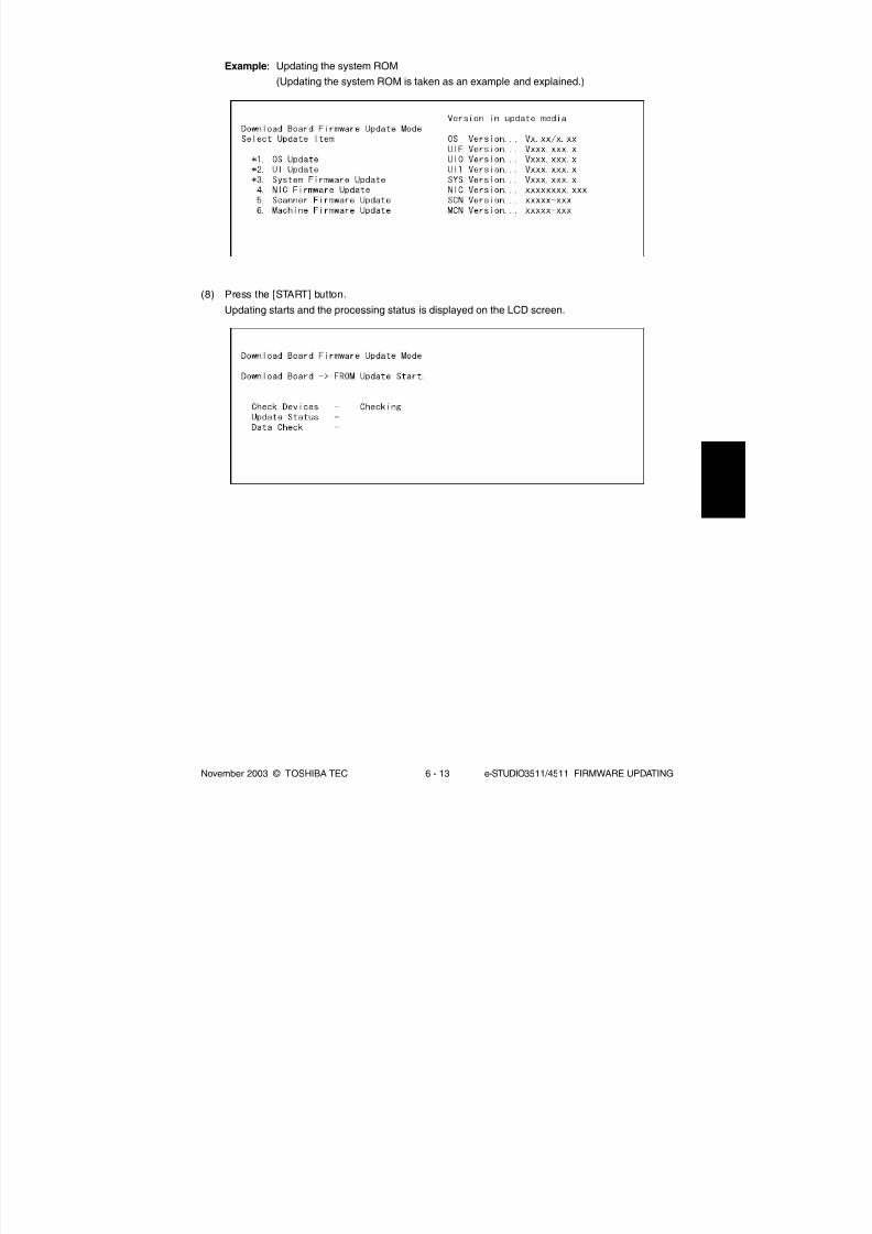
8/2/2019 ES-3511 Service Handbook
http://slidepdf.com/reader/full/es-3511-service-handbook 463/543
November 2003 © TOSHIBA TEC 6 - 13 e-STUDIO3511/4511 FIRMWARE UPDATING
Example: Updating the system ROM
(Updating the system ROM is taken as an example and explained.)
(8) Press the [START] button.
Updating starts and the processing status is displayed on the LCD screen.

8/2/2019 ES-3511 Service Handbook
http://slidepdf.com/reader/full/es-3511-service-handbook 464/543
e-STUDIO3511/4511 FIRMWARE UPDATING 6 - 14 November 2003 © TOSHIBA TEC
(9) “Update Completed!!” is displayed at the bottom of the LCD screen after the updating is
completed properly.
“Update Failed.” is displayed at the bottom of the LCD screen when the updating is not com-
pleted properly. Turn OFF the power, and then check the following items. After confirming and
clearing the problems, restart updating from the beginning.
• Is the download jig connected properly?
• Is the updating data written to the download jig properly?
• Do the download jig and the equipment operate properly?

8/2/2019 ES-3511 Service Handbook
http://slidepdf.com/reader/full/es-3511-service-handbook 465/543
November 2003 © TOSHIBA TEC 6 - 15 e-STUDIO3511/4511 FIRMWARE UPDATING
NIC error message
NIC Error Message
NIC UPDATE FAILED 1
NIC UPDATE FAILED 2
NIC UPDATE FAILED 3
NIC UPDATE FAILED 4
NIC UPDATE FAILED 5
NIC UPDATE FAILED 6
NIC UPDATE FAILED 7
Error Contents
NIC initialization time-out
ATA driver initialization error
HDD partition mount error
NIC setting information
backup error
NIC firmware transfer error
NIC firmware writing error
NIC status time-out
Prescription
The IP address may not be assigned
correctly.
• Is the IP address assigned correctly?
• Does the IP address conflict with the other
system?
If the error still occurs, replace the NIC
board because it may be destroyed.
The HDD cable may be disconnected.
• Is the HDD cable connected correctly?
If the HDD cable is connected correctly,
replace the SYS board because it may be
destroyed.
Replace the HDD because it may be
destroyed.
Replace the HDD because it may be
destroyed.
Replace the NIC board because it may be
destroyed.
Replace the NIC board because it may bedestroyed.
Replace the NIC board because it may be
destroyed.
04/10
* When the updating of the NIC firmware is failed, an error message is displayed as the figure
below. Turn OFF the power and then check the above-mentioned items. After confirming them,
select only “4. NIC Firmware Update” and restart updating from the beginning. This may
complete the updating properly.
If the updating of the NIC firmware is still failed, check the prescription corresponding to the error
message. After confirming and clearing the problem, restart updating from the beginning.
Notes:
If the updating of the NIC firmware is not completed properly, wait 5 minutes or more from the
beginning of the updating before turning OFF the power, and then restart updating from the
beginning. If you turn OFF the power within 5 minutes, HDD may be destroyed.

8/2/2019 ES-3511 Service Handbook
http://slidepdf.com/reader/full/es-3511-service-handbook 466/543
e-STUDIO3511/4511 FIRMWARE UPDATING 6 - 16 November 2003 © TOSHIBA TEC
(b) Confirmation of the updated data
After the updating is completed, check each data version in the Setting Mode (08) to confirm that
the data was overwritten properly.
<Updating System ROM>
08-900: System ROM version
08-920: FROM basic section software version
08-921: FROM internal program version08-922: UI data fixed section version
08-923: UI data common section version
08-930: Version of UI data in FROM displayed at power ON
<Updating Engine ROM>
08-903: Engine ROM version
<Updating Scanner ROM>
08-905: Scanner ROM version
<Updating NIC ROM>
08-916: NIC ROM version
04/10
(10) Turn OFF the power, remove the download jig and install the cover plate and the connector
cover.
(11) Perform the initialization of the updating data (NVRAM updating).
a. Turn ON the power while [0] button and [8] button are pressed simultaneously.
b. Key in “947”, and then press the [START] button.
c. Press the [INITIALIZE] button.

8/2/2019 ES-3511 Service Handbook
http://slidepdf.com/reader/full/es-3511-service-handbook 467/543
November 2003 © TOSHIBA TEC 6 - 17 e-STUDIO3511/4511 FIRMWARE UPDATING
(c) Display during the update
The processing status is displayed as follows on the LCD screen during the update.
(As an example, the display for updating the system ROM is explained below.)
Press [START] button after selecting the item to
be updated. The device check starts.
When the device check completes, erasing the
data in the ROM of the equipment starts.
When erasing the data completes, copying the
data to the ROM of the equipment starts.
Turn ON the power while [8] button and [9] button are pressed simultaneously.
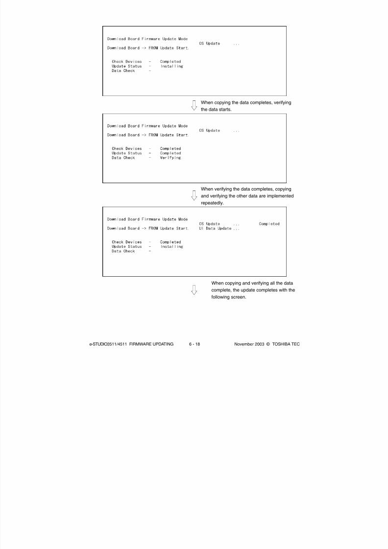
8/2/2019 ES-3511 Service Handbook
http://slidepdf.com/reader/full/es-3511-service-handbook 468/543
e-STUDIO3511/4511 FIRMWARE UPDATING 6 - 18 November 2003 © TOSHIBA TEC
When copying the data completes, verifying
the data starts.
When verifying the data completes, copying
and verifying the other data are implemented
repeatedly.
When copying and verifying all the data
complete, the update completes with the
following screen.

8/2/2019 ES-3511 Service Handbook
http://slidepdf.com/reader/full/es-3511-service-handbook 469/543
November 2003 © TOSHIBA TEC 6 - 19 e-STUDIO3511/4511 FIRMWARE UPDATING
* If an error occurs, the following error message is displayed and the update is interrupted.
Error message

8/2/2019 ES-3511 Service Handbook
http://slidepdf.com/reader/full/es-3511-service-handbook 470/543
e-STUDIO3511/4511 FIRMWARE UPDATING 6 - 20 November 2003 © TOSHIBA TEC
6.1.3 Writing the data to the download jig (PWA-DWNLD-350-JIG)
The download jig (PWA-DWNLD-350-JIG) differs from the existing jigs in that the Flash ROM is mounted
on the board of the jig directly. The ROM writer adapter (PWA-DL-ADP-350) is required to write data to
these Flash ROMs. Connect the download jig with the ROM writer via ROM writer adapter to write data.
For the procedure to write data, refer to the download procedure, instruction manual of each ROM writer,
or others.
Note:
There are two types of the ROM writer adapter. Use the proper one according to the ROM writer to be
used. Applicable type of the adapter for the ROM writer can be confirmed by the model name indicated on
the board. Confirm that the adapter is available for the ROM writer to be used before connecting them. If
an unapplied adapter is connected, the application of the ROM writer judges it as an error and writing the
data cannot be implemented. Applicable combinations of the ROM writer and adapter are as follows.
ROM writer
Minato Electronics MODEL 1881XP
(or equivalent)
Minato Electronics MODEL 1893/1895/1931/1940
(or equivalent)
[PWA-DL-ADP-350-1881]
ROM writer adapter
PWA-DL-ADP-350-1881
(model 1881)
PWA-DL-ADP-350-1931
(model 1931)
[PWA-DL-ADP-350-1931]
model 1931
(LV650)
model 1881model 1931
(LV650)
model 1881
PC
Download jig
(PWA-DWNLD-350-JIG)
ROM writer adapter
(PWA-DL-ADP-350)
ROM writer

8/2/2019 ES-3511 Service Handbook
http://slidepdf.com/reader/full/es-3511-service-handbook 471/543
November 2003 © TOSHIBA TEC 6 - 21 e-STUDIO3511/4511 FIRMWARE UPDATING
6.1.4 K-PWA-DLM-320
The firmware of the equipment (engine ROM, scanner ROM) and the option (RADF ROM, Finisher
ROM, FAX ROM) can be updated individually by using K-PWA-DLM-320. Update the ROM data
written on each board according to the need such as the case of replacing the board.
The data to be overwritten by this update are as follows.
<Updating Engine ROM>
Engine ROM data
<Updating Scanner ROM>
Scanner ROM data
<Updating RADF ROM>
RADF ROM data
<Updating Finisher ROM>
• Finisher firmware
• Saddle stitcher firmware
<Updating FAX ROM>
FAX ROM data
(a) Precaution when writing the data
• Set the writing voltage (VID) to 3.3 V.
• When writing the data, set the address from 0 to 3FFFFF. The data may not be written cor-
rectly if it is not set.
• The Flash ROM in which the data will be written, on the download jig is selected by switching
the rotary switch on the adapter. Be sure to switch the rotary switch on the adapter depend-
ing on the data (file) to be written.
Rotary
Switch
1
2
3
4
5
6
Master Data
(PWA-DWNLD-350-JIG2)
ROM. bin
1
2
3
4
N/A
System, Engine, Scanner and NIC data
(PWA-DWNLD-350-JIG1)
ROM. bin
Sysfirm. bin
N/A
N/A
N/A
N/A
Flash ROM
ROM1
ROM2
ROM3
ROM4
ROM5
ROM6
File Name
Note:
Be sure not to confuse different ROM Versions since the file name is identical although the ROM version
is different.
04/07
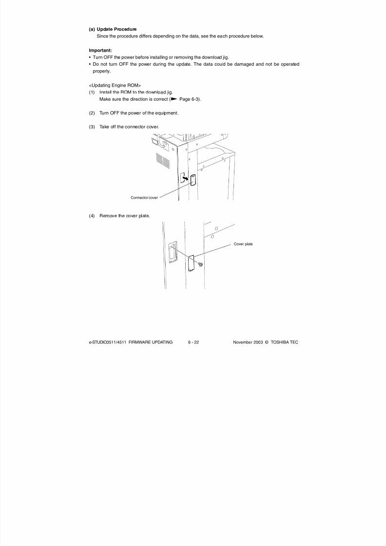
8/2/2019 ES-3511 Service Handbook
http://slidepdf.com/reader/full/es-3511-service-handbook 472/543
e-STUDIO3511/4511 FIRMWARE UPDATING 6 - 22 November 2003 © TOSHIBA TEC
(a) Update Procedure
Since the procedure differs depending on the data, see the each procedure below.
Important:
• Turn OFF the power before installing or removing the download jig.
• Do not turn OFF the power during the update. The data could be damaged and not be operated
properly.
<Updating Engine ROM>
(1) Install the ROM to the download jig.
Make sure the direction is correct ( Page 6-3).
(2) Turn OFF the power of the equipment.
(3) Take off the connector cover.
Connector cover
Cover plate
(4) Remove the cover plate.

8/2/2019 ES-3511 Service Handbook
http://slidepdf.com/reader/full/es-3511-service-handbook 473/543
November 2003 © TOSHIBA TEC 6 - 23 e-STUDIO3511/4511 FIRMWARE UPDATING
(5) Connect the download jig with the jig connector (CN344) on the logic PC board (LGC board).
(6) Turn ON the power while [0] button and [8] button are pressed simultaneously.
Updating starts automatically and the LED on the download jig lights.
(7) When the update is completed properly, the LED on the download jig blinks. The LED starts
blinking in approx. 20 sec. since the update starts. It is assumed that the update is failed if it does
not start blinking even though 1 min. has passed. In this case, turn OFF the power and check the
following items. Then, clear the problem and restart updating from the beginning.
• Is the download jig connected properly?
• Is the ROM installed to the download jig properly?
• Is the updating data written on the ROM of the download jig properly?
• Do the download jig and the equipment operate properly?
(8) Turn OFF the power, remove the download jig and install the cover plate and the connector cover.
Connector
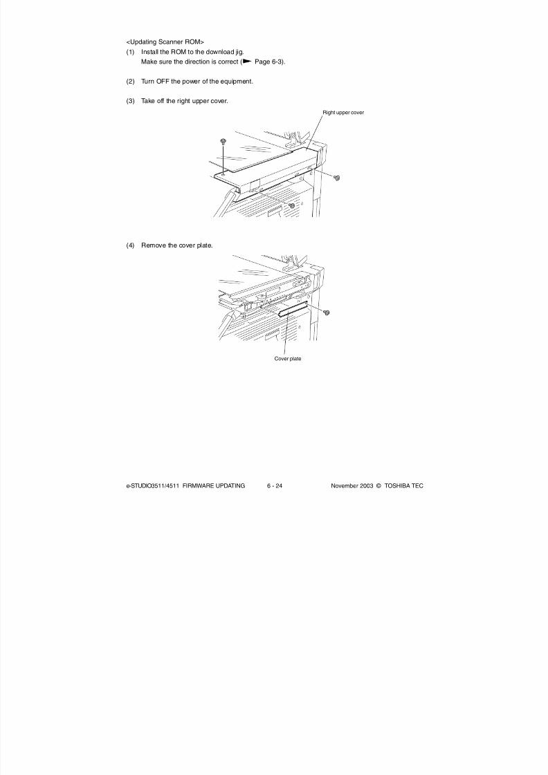
8/2/2019 ES-3511 Service Handbook
http://slidepdf.com/reader/full/es-3511-service-handbook 474/543
e-STUDIO3511/4511 FIRMWARE UPDATING 6 - 24 November 2003 © TOSHIBA TEC
<Updating Scanner ROM>
(1) Install the ROM to the download jig.
Make sure the direction is correct ( Page 6-3).
(2) Turn OFF the power of the equipment.
(3) Take off the right upper cover.
(4) Remove the cover plate.
Right upper cover
Cover plate

8/2/2019 ES-3511 Service Handbook
http://slidepdf.com/reader/full/es-3511-service-handbook 475/543
November 2003 © TOSHIBA TEC 6 - 25 e-STUDIO3511/4511 FIRMWARE UPDATING
(5) Connect the download jig with the jig connector (CN16) on the scanning section control PC
board (SLG board).
(6) Turn ON the power while [0] button and [8] button are pressed simultaneously.
Updating starts automatically and the LED on the download jig lights.
(7) After the update is completed properly, the LED on the download jig blinks. The LED starts blink-
ing in approx. 20 sec. since the update starts. It is assumed that the update is failed if it does not
start blinking even though 1 min. has passed. In this case, turn OFF the power and check the
following items. Then, clear the problem and restart updating from the beginning.
• Is the download jig connected properly?
• Is the ROM installed to the download jig properly?
• Is the updating data written on the ROM of the download jig properly?
• Do the download jig and the equipment operate properly?
(8) Turn OFF the power, remove the download jig and install the cover plate and the right upper
cover.
Connector

8/2/2019 ES-3511 Service Handbook
http://slidepdf.com/reader/full/es-3511-service-handbook 476/543
e-STUDIO3511/4511 FIRMWARE UPDATING 6 - 26 November 2003 © TOSHIBA TEC
<Updating RADF ROM>
(1) Install the ROM to the download jig.
Make sure the direction is correct ( Page 6-3).
(2) Turn OFF the power of the equipment.
(3) Take off the RADF rear cover.
(4) Connect the download jig with the jig connector (CN14) on the RADF control PC board.
(5) Turn ON the power while [0] button and [8] button are pressed simultaneously.
Updating starts automatically and the LED on the download jig lights.
RADF rear cover
Connector

8/2/2019 ES-3511 Service Handbook
http://slidepdf.com/reader/full/es-3511-service-handbook 477/543
November 2003 © TOSHIBA TEC 6 - 27 e-STUDIO3511/4511 FIRMWARE UPDATING
(6) After the update is completed properly, the LED on the download jig blinks. The LED starts
blinking in approx. 15 sec. since the update starts. It is assumed that the update is failed if it does
not start blinking even though 1 min. has passed. In this case, turn OFF the power and check
the following items. Then, clear the problem and restart updating from the beginning.
• Is the download jig connected properly?
• Is the ROM installed to the download jig properly?
• Is the updating data written on the ROM of the download jig properly?
• Do the download jig and the equipment operate properly?
(7) Turn OFF the power, remove the download jig and install the RADF rear cover.

8/2/2019 ES-3511 Service Handbook
http://slidepdf.com/reader/full/es-3511-service-handbook 478/543
e-STUDIO3511/4511 FIRMWARE UPDATING 6 - 28 November 2003 © TOSHIBA TEC
* Connect the finisher interface cable with the equipment after removing the finisher rear cover.
(4) Connect the download jig with the jig connector on the finisher control PC board.
[MJ-1023] [MJ-1024]
Finisher rear cover Finisher rear cover
Connector
<Updating Finisher ROM>
Finisher firmware (MJ-1023/1024) and saddle stitcher firmware (MJ-1024 only) are written on the
finisher ROM. These two kinds of firmware can be updated individually by installing the download jig
to the finisher control PC board.
Tip:
The following updates are needed according to the finisher model.
• MJ-1023 (Console type):
Only the update of “Finisher firmware” is needed.
• MJ-1024 (Console type with the saddle stitcher):
Two kinds of update “Finisher firmware” and “Saddle stitcher firmware” are needed.
(1) Install the ROM to the download jig.
Make sure the direction is correct ( Page 6-3).
(2) Turn OFF the power of the equipment.
(3) Take off the finisher rear cover.

8/2/2019 ES-3511 Service Handbook
http://slidepdf.com/reader/full/es-3511-service-handbook 479/543
November 2003 © TOSHIBA TEC 6 - 29 e-STUDIO3511/4511 FIRMWARE UPDATING
(5) Change the setting of the DIP switch on the finisher contorol PC board.
Change the setting of the DIP switch as follows according to the firmware to be updated.
Note:
Record the current settings of the DIP switch before changing them. After the updating is
completed, return the DIP switch to the status as record.
<Updating Finisher Firmware>
Change all the setting of the DIP switch (1-8) to OFF.
<Updating Saddle Stitcher Firmware>
Change the setting of the DIP switch 1-6 to OFF and 7-8 to ON.
(6) Turn ON the power while [0] button and [8] button are pressed simultaneously.
Updating starts automatically and the LED on the download jig lights.
Tip:
The processing status can be confirmed by the lighting of the LED (LED 101-103) on the finisher
control board.
Processing status
0% or above
15% or above
30% or above
45% or above
60% or above
75% or above
90% or above
LED103
OFF
OFF
OFF
ON
ON
ON
ON
LED102
OFF
ON
ON
OFF
OFF
ON
ON
LED101
ON
OFF
ON
OFF
ON
OFF
ON
LED

8/2/2019 ES-3511 Service Handbook
http://slidepdf.com/reader/full/es-3511-service-handbook 480/543
e-STUDIO3511/4511 FIRMWARE UPDATING 6 - 30 November 2003 © TOSHIBA TEC
(7) After the update is completed properly, the LED on the download jig blinks slowly (at interval of
0.8 sec). The LED starts blinking in approx. 30 sec. (finisher section) or 2 min. 30 sec. (saddle
stitcher section) since the update starts. It is assumed that the update is failed if it does not start
blinking even though 1 min. has passed (finisher section) or 3 min. (saddle stitcher section), or
LED flashes fast (at interval of 0.1 sec.). In this case, turn OFF the power and check the following
items. Then, clear the problem and restart updating from the beginning.
• Is the download jig connected properly?
• Is the ROM installed to the download jig properly?
• Is the updating data written on the ROM of the download jig properly?
• Do the download jig and the equipment operate properly?
• Is the DIP switch on the finisher control PC board set properly according to the download
section (finisher or saddle stitcher)?
(8) Turn OFF the power, remove the download jig and return the DIP switch to the status before updating.
(9) Install the finisher rear cover.

8/2/2019 ES-3511 Service Handbook
http://slidepdf.com/reader/full/es-3511-service-handbook 481/543
November 2003 © TOSHIBA TEC 6 - 31 e-STUDIO3511/4511 FIRMWARE UPDATING
<Updating FAX ROM>
Important:
• Before updating the FAX ROM, make sure to print out the current Function list for maintenance,
Function list (ADMIN), Phone book number information and Group number information. In case the
updating is failed and the registered information of the users is lost for some reason, re-register the
user information referring to the lists and recover it.
• Confirm the following items before turning OFF the power of the equipment. Turning OFF the power
may clear the data below.
• Confirm that the “MEMORY RX” LED is OFF and there are no memory reception data.
• Print the “Mailbox/Relay box report” and then confirm that there are no F code data.
• Press the [JOB STATUS] button to display the screen and then confirm that there are no memory
transmission data.
(1) Install the ROM to the download jig.
Make sure the direction is correct ( Page 6-3).
(2) Turn OFF the power of the equipment.
(3) Take off the connector cover.
Connector cover

8/2/2019 ES-3511 Service Handbook
http://slidepdf.com/reader/full/es-3511-service-handbook 482/543
e-STUDIO3511/4511 FIRMWARE UPDATING 6 - 32 November 2003 © TOSHIBA TEC
(4) Remove the cover plate.
(5) Connect the download jig with the jig connector (CN602) on the FAX board.
(6) Turn ON the power while [0] button and [8] button are pressed simultaneously.
Updating starts automatically and the LED on the download jig lights.
(7) After the update is completed properly, the LED on the download jig blinks. The LED starts
blinking in approx. 30 sec. since the update starts. It is assumed that the update is failed if it does
not start blinking even though 1 min. has passed. In this case, turn OFF the power and check
the blinking items. Then, clear the problem and restart updating from the beginning.
• Is the download jig connected properly?• Is the ROM installed to the download jig properly?
• Is the updating data written on the ROM of the download jig properly?
• Do the download jig and the equipment operate properly?
(8) Turn OFF the power, remove the download jig and install the cover plate and the connector cover.
Cover plate
Connector

8/2/2019 ES-3511 Service Handbook
http://slidepdf.com/reader/full/es-3511-service-handbook 483/543
November 2003 © TOSHIBA TEC 6 - 33 e-STUDIO3511/4511 FIRMWARE UPDATING
(9) In the FAX Clearing Mode, perform the “FAX Set Up”.
a. Confirm the destination setting is correct in the Setting Mode (08).
08-201: Destination setting of the equipment
08-701: Destination setting of the FAX machine
b. Turn ON the power while [1] button and [*] button are pressed simultaneously.
c. Key in “100”.
d. Press the [START] button.
Note:
If the equipment does not work properly after the operation (9), follow the procedure below and
then perform the “Clearing the image data” in the FAX Clearing Mode to erase the image data in
the memory.
a. Confirm the destination setting is correct in the Setting Mode (08).
08-201: Destination setting of the equipment
08-701: Destination setting of the FAX machine
b. Turn ON the power while [1] button and [*] button are pressed simultaneously.
c. Key in “102”.
d. Press the [START] button.

8/2/2019 ES-3511 Service Handbook
http://slidepdf.com/reader/full/es-3511-service-handbook 484/543
e-STUDIO3511/4511 FIRMWARE UPDATING 6 - 34 November 2003 © TOSHIBA TEC
(b) Confirmation of the updated data
After the updating is completed, check each data version in Setting Mode (08) to confirm that the
data was overwritten properly.
<Updating Engine ROM>
08-903: Engine ROM version
<Updating Scanner ROM>
08-905: Scanner ROM version
<Updating RADF ROM>
08-907: RADF ROM version
<Updating Finisher ROM>
08-908: Finisher ROM version
<Updating FAX ROM>
08-915: FAX ROM version

8/2/2019 ES-3511 Service Handbook
http://slidepdf.com/reader/full/es-3511-service-handbook 485/543
November 2003 © TOSHIBA TEC 6 - 35 e-STUDIO3511/4511 FIRMWARE UPDATING
OS:
Windows 98
Windows Me
Windows NT4.0
Windows 2000
Windows XP
Connecting cable:
USB cable or
RS-232C cable
PC:
IBM PC/AT or compatible machine
(USB port or RS-232C port is needed)
The official name of Windows 98 is Microsoft Windows 98 Operating System.
• The official name of Windows Me is Microsoft Windows Millennium Edition Operating System.
• The official name of Windows 2000 is Microsoft Windows 2000 Operating System.
• The official name of Windows XP is Microsoft Windows XP Operating System.
• Microsoft, Windows and the brand names and product names of other Microsoft products are trademarks or
registered trademarks of US Microsoft Corporation in the US and other countries.
• IBM PC/AT is a registered trademark of US International Business Machines Corporation.
6.2 Firmware Updating with FSMS (Field Service Manager)
In this equipment, it is feasible to update the downloaded firmware from the PC connected with the
equipment by using the utility software ”FSMS (Field Service Manager)”. Firmware can be also down-
loaded through USB, in addition to an existing serial transfer through RS-232C.
This chapter explains only the firmware downloading method with FSMS. Refer to the Field Service
Manager Operator’s Manual for the details about installation method and functions of FSMS.
Important:
• Updating with USB connection is more recommended since the data transfer speed is lower and it
takes more time to update in the serial connection with RS-232C cable.
Example: Updating time for system ROM (sysfirm.tz : Approx. 8 MB)
RS-232C connection: Approx. 1 hour and 20 minutes
USB connection: Approx. 10 minutes
* The updating time noted above is a reference. It may vary depending on the performance
of the PC used.
• Updating through USB is not feasible for Windows NT4.0 since this operating system does not support
USB. When this system is used, update in the serial connection with RS-232C cable.
• When updating through USB (using FSMS), a printer driver needs to be installed in the PC in advance.
Refer to the Printing Guide about the installation method of the printer driver.

8/2/2019 ES-3511 Service Handbook
http://slidepdf.com/reader/full/es-3511-service-handbook 486/543
e-STUDIO3511/4511 FIRMWARE UPDATING 6 - 36 November 2003 © TOSHIBA TEC
The types of firmware which can be updated with this method are as follows in the table below.
Firmware
Master data
System ROM
Engine ROM
Scanner ROM
NIC ROM
Data file name
uidata2.tz, uidata3.tz, uidata4.tz, uidata5.tz, uidata6.tz,
uidata7.tz, webdata1.tz, webdata2.tz, webdata3.tz,
webdata4.tz, webdata5.tz, webdata6.tz, all.tz
sysfirm.tz, uidataF.tz, uidata0.tz, uidata1.tz
mfirm.tz
scnfirm.tz
nicfirm.tz
Stored
Hard disk
System control PC board
(SYS board)
Logic PC board
(LGC board)
Scanning section control PC board
(SLG board)
NIC board
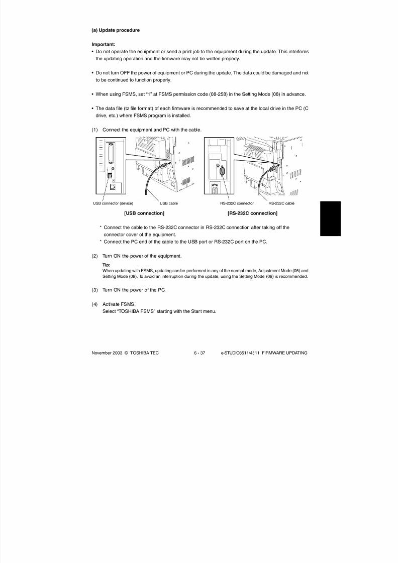
8/2/2019 ES-3511 Service Handbook
http://slidepdf.com/reader/full/es-3511-service-handbook 487/543
November 2003 © TOSHIBA TEC 6 - 37 e-STUDIO3511/4511 FIRMWARE UPDATING
(a) Update procedure
Important:
• Do not operate the equipment or send a print job to the equipment during the update. This interferes
the updating operation and the firmware may not be written properly.
• Do not turn OFF the power of equipment or PC during the update. The data could be damaged and not
to be continued to function properly.
• When using FSMS, set “1” at FSMS permission code (08-258) in the Setting Mode (08) in advance.
• The data file (tz file format) of each firmware is recommended to save at the local drive in the PC (C
drive, etc.) where FSMS program is installed.
(1) Connect the equipment and PC with the cable.
[USB connection] [RS-232C connection]
* Connect the cable to the RS-232C connector in RS-232C connection after taking off the
connector cover of the equipment.
* Connect the PC end of the cable to the USB port or RS-232C port on the PC.
(2) Turn ON the power of the equipment.
Tip:
When updating with FSMS, updating can be performed in any of the normal mode, Adjustment Mode (05) and
Setting Mode (08). To avoid an interruption during the update, using the Setting Mode (08) is recommended.
(3) Turn ON the power of the PC.
(4) Activate FSMS.
Select “TOSHIBA FSMS” starting with the Star t menu.
USB connector (device) USB cable RS-232C connector RS-232C cable

8/2/2019 ES-3511 Service Handbook
http://slidepdf.com/reader/full/es-3511-service-handbook 488/543
e-STUDIO3511/4511 FIRMWARE UPDATING 6 - 38 November 2003 © TOSHIBA TEC
(5) Enter the login password and click the [OK] button.
* Set the login password at the installation of FSMS.
(6) Click the [F/W Download] button.
(7) Select the model name of the equipment to be updated from the drop-down menu and click the
[OK] button.

8/2/2019 ES-3511 Service Handbook
http://slidepdf.com/reader/full/es-3511-service-handbook 489/543
November 2003 © TOSHIBA TEC 6 - 39 e-STUDIO3511/4511 FIRMWARE UPDATING
(8) Click the [OFFLINE] button.
(9) Select the transmit media and click the [OK] button.
In case of RS-232C connection: Select “Serial”
In case of USB connection: Select “USB”
* The connection status between the printer driver installed in the PC and the equipment to be
connected is displayed only when “USB” is selected. Select the equipment to be updated and
click the [Activate FSMS] button.
Tip:
The content of ”Status” display can be renewed to the latest status by clicking the [Refresh] button. When the
status is displayed as “Disconnected” because the start up of the equipment is delayed, the status can be
renewed to “Connected” by clicking this.

8/2/2019 ES-3511 Service Handbook
http://slidepdf.com/reader/full/es-3511-service-handbook 490/543
e-STUDIO3511/4511 FIRMWARE UPDATING 6 - 40 November 2003 © TOSHIBA TEC
(10) Check the firmware to be updated and click the [OK] button.
Tip:
The relation between the types of firmware to be updated and items to check is as follows in the table below.
Item
Program
UI Data
Common UI Data
1st Language UI Data
MROM
Scan ROMNIC ROM
Generic
Data file name to update
sysfirm.tz
uidataF.tz
uidata0.tz
uidata1.tz
mfirm.tz
scnfirm.tznicfirm.tz
uidata2.tz, uidata3.tz, uidata4.tz, uidata5.tz, uidata6.tz,
uidata7.tz, webdata1.tz, webdata2.tz, webdata3.tz,
webdata4.tz, webdata5.tz, webdata6.tz, all.tz
Firmware
System ROM
Engine ROM
Scanner ROMNIC ROM
Master data

8/2/2019 ES-3511 Service Handbook
http://slidepdf.com/reader/full/es-3511-service-handbook 491/543
November 2003 © TOSHIBA TEC 6 - 41 e-STUDIO3511/4511 FIRMWARE UPDATING
(11) Select the data file to be updated and click the [OK] button.
There are two data filing methods: Selecting the multiple data files in a batch (select the folder
where the files are saved) and selecting each data file individually.
• Selecting the multiple data files in a batch
a. Select “Download File Folder”.
b. Click the [Browse] button and select the folder where the files are saved.
• Selecting each data file individually
a. Select “File Name Conversion”.b. Click the [Browse] button of each data and select the file. When “Generic Driver” is used,
check the checkbox of the file to be selected.
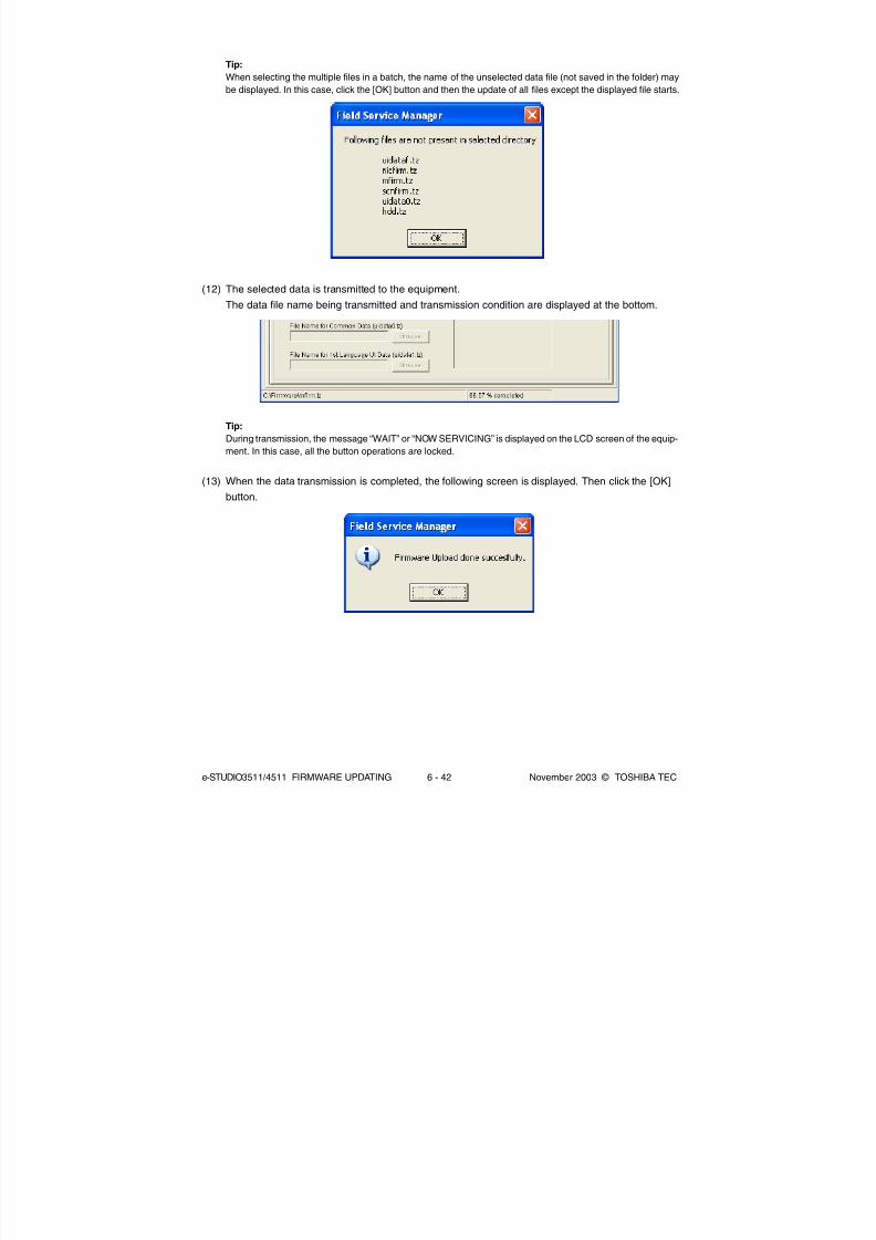
8/2/2019 ES-3511 Service Handbook
http://slidepdf.com/reader/full/es-3511-service-handbook 492/543
e-STUDIO3511/4511 FIRMWARE UPDATING 6 - 42 November 2003 © TOSHIBA TEC
Tip:
When selecting the multiple files in a batch, the name of the unselected data file (not saved in the folder) may
be displayed. In this case, click the [OK] button and then the update of all files except the displayed file starts.
(12) The selected data is transmitted to the equipment.
The data file name being transmitted and transmission condition are displayed at the bottom.
Tip:
During transmission, the message “WAIT” or “NOW SERVICING” is displayed on the LCD screen of the equip-
ment. In this case, all the button operations are locked.
(13) When the data transmission is completed, the following screen is displayed. Then click the [OK]
button.

8/2/2019 ES-3511 Service Handbook
http://slidepdf.com/reader/full/es-3511-service-handbook 493/543
November 2003 © TOSHIBA TEC 6 - 43 e-STUDIO3511/4511 FIRMWARE UPDATING
(14) The equipment restarts automatically and the items to be updated and processing status are
displayed on the LCD screen.
(15) “Update Completed!!” is displayed at the bottom of the LCD screen after the updating is com-
pleted properly.
04/10

8/2/2019 ES-3511 Service Handbook
http://slidepdf.com/reader/full/es-3511-service-handbook 494/543
e-STUDIO3511/4511 FIRMWARE UPDATING 6 - 44 November 2003 © TOSHIBA TEC
“Update Failed!!” is displayed at the bottom of the LCD screen when the updating is not com-
pleted properly. Turn OFF the power, and then check the following items. After confirming and
clearing the problems, restart updating from the beginning.
• Are the equipment and PC properly connected?
• Is the selected data file proper?
• Do the cable, equipment and PC operate properly?
• Are FSMS and printer driver properly installed?
* When the updating of the NIC firmware is failed, an error message is displayed as the figure
below. Turn OFF the power and then check the above-mentioned items. After confirming them,
select only ”NIC ROM” (6. NIC Firmware Update) and restart updating from the beginning. This
may complete the updating properly.
NIC error message
04/10

8/2/2019 ES-3511 Service Handbook
http://slidepdf.com/reader/full/es-3511-service-handbook 495/543
November 2003 © TOSHIBA TEC 6 - 45 e-STUDIO3511/4511 FIRMWARE UPDATING
Notes:
If the updating of the NIC firmware is not completed properly, wait 5 minutes or more from the
beginning of the updating before turning OFF the power, and then restart updating from the
beginning. If you turn OFF the power within 5 minutes, HDD may be destroyed.
(16) Turn OFF the power of the equipment.
(17) Perform the initialization of the updating data (NVRAM updating).
a. Turn ON the power while [0] button and [8] button are pressed simultaneously.
b. Key in “947”, and then press the [START] button.
c. Press the [INITIALIZE] button.
NIC Error Message
NIC UPDATE FAILED 1
NIC UPDATE FAILED 2
NIC UPDATE FAILED 3
NIC UPDATE FAILED 4
NIC UPDATE FAILED 5
NIC UPDATE FAILED 6
NIC UPDATE FAILED 7
Error Contents
NIC initialization time-out
ATA driver initialization error
HDD partition mount error
NIC setting information
backup errorNIC firmware transfer error
NIC firmware writing error
NIC status time-out
Prescription
The IP address may not be assigned
correctly.
• Is the IP address assigned correctly?
• Does the IP address conflict with the
other system?
If the error still occurs, replace the NIC
board because it may be destroyed.
The HDD cable may be disconnected.
• Is the HDD cable connected correctly?
If the HDD cable is connected correctly,
replace the SYS board because it may be
destroyed.
Replace the HDD because it may be
destroyed.
Replace the HDD because it may be
destroyed.Replace the NIC board because it may be
destroyed.
Replace the NIC board because it may be
destroyed.
Replace the NIC board because it may be
destroyed.
04/10
If the updating of the NIC firmware is still failed, check the prescription corresponding to the error
message. After confirming and clearing the problem, restart updating from the beginning.

8/2/2019 ES-3511 Service Handbook
http://slidepdf.com/reader/full/es-3511-service-handbook 496/543
e-STUDIO3511/4511 FIRMWARE UPDATING 6 - 46 November 2003 © TOSHIBA TEC
(b) Confirmation of the updated data
After the updating is completed, check each data version in the Setting Mode (08) to confirm that
the data was overwritten properly.
<Updating Master data>
08-925: Version of UI data language 2 in HDD
08-926: Version of UI data language 3 in HDD
08-927: Version of UI data language 4 in HDD
08-928: Version of UI data language 5 in HDD
08-929: Version of UI data language 6 in HDD
08-931: Version of UI data language 7 in HDD
08-933: HDD data unit version
08-934: Version of Web UI data language 1 in HDD
08-935: Version of Web UI data language 2 in HDD
08-936: Version of Web UI data language 3 in HDD
08-937: Version of Web UI data language 4 in HDD
08-938: Version of Web UI data language 5 in HDD
08-939: Version of Web UI data language 6 in HDD
<Updating System ROM>
08-900: System ROM version
08-922: UI data fixed section version
08-923: UI data common section version
08-924: Version of UI data language 1 in HDD
08-930: Version of UI data in FROM displayed at power ON
<Updating Engine ROM >
08-903: Engine ROM version
<Updating Scanner ROM>
08-905: Scanner ROM version
<Updating NIC ROM>
08-916: NIC ROM version

8/2/2019 ES-3511 Service Handbook
http://slidepdf.com/reader/full/es-3511-service-handbook 497/543
November 2003 © TOSHIBA TEC 6 - 47 e-STUDIO3511/4511 FIRMWARE UPDATING
Data file name
1, 2, 3 ... n
* The file name should be consecutive numbers from 1
to “n” without file extension. The capacity of each file
is approx. 8 MB. However, the file capacity of “n” (last
number) may be less than 8 MB.
sysfirm.bin, ROM.bin
ROM.bin
Stored
Hard disk
System control PC board
(SYS board)
Logic PC board
(LGC board)
Scanning section control PC board
(SLG board)
NIC board
6.3 Firmware Updating with USB Storage Device
In this equipment, it is feasible to update the firmware by connecting the USB storage device on which
the firmware data is written to the USB connector mounted on the system control PC board and turning
ON the power.
The type of firmware to be updated can be selected on the LCD screen in this method. This allows to
update only the necessary firmware individually or to update all firmware in a batch.
The type of firmware which can be updated with this method are as follows in the table below. Also, the
data file of each firmware can be used commonly in the updating methods with USB storage device and
Download jig.
Firmware
Master data
System ROM
Engine ROM
Scanner ROM
NIC ROM

8/2/2019 ES-3511 Service Handbook
http://slidepdf.com/reader/full/es-3511-service-handbook 498/543
e-STUDIO3511/4511 FIRMWARE UPDATING 6 - 48 November 2003 © TOSHIBA TEC
Important:
• The following USB storage devices are recommended for updating.
• MELCO ClipDrive (RUF-C128M)
• Lexar Media JumpDrive (RD128-231)
• Iomega Mini USB Drive (Mini 128MB USB Drive)
• Only the USB storage device which meets the following conditions should be used for updating. Be
careful since updating with any device other than the above is never guaranteed.
• A combination USB storage device with a flash memory (to be connected directly to the USB port)
and its capacity is 64 MB or more
• A USB storage device which is complied with the following standards regulated by USB-IF (USB
Implementers Forum)
Class number: 8 (=08h) (Mass-storage class)
Sub-class number: 6 (=06h) (SCSI transfer command set)
Protocol number: 80 (=50h) (Bulk-Only)
* Most common USB storage devices are complied with the specification above and can be used
for updating. However, the operation in this equipment is not always guaranteed since the most
of these devices are developed based on the use in PC environment (Windows or Macintosh).
Therefore, confirm thoroughly that the device is operational in this equipment when purchasing
the device.
• The USB storage device complied with USB1.1 and USB2.0 can be used for updating. However, the
update is performed in the speed of USB1.1 when the device complied with USB2.0 is used.
• Do not update the firmware by any storage device other than a flash memory (such as a USB connectiontype memory card reader, CD/DVD drive or hard disk) since it is never guaranteed.

8/2/2019 ES-3511 Service Handbook
http://slidepdf.com/reader/full/es-3511-service-handbook 499/543
November 2003 © TOSHIBA TEC 6 - 49 e-STUDIO3511/4511 FIRMWARE UPDATING
(4) Connect the USB storage device to the USB connector (host) on the SYS board.
Cover plate
USB connector (host)
USB storage device
(a) Update procedure
Important:
• The file system of USB storage device should be formatted in FAT format. Be careful since the devices
formatted in FAT32 or NTFS format will not be operated. The file system can be confirmed on the
properties in applications such as Explorer of Windows.
• Do not turn OFF the power during the update. The data could be damaged and not to be operated
properly.
(1) Connect the USB storage device to the PC and write the data file.
• Confirm the data file name before writing ( Page 6-44).
• The file system of USB storage device should be formatted in FAT format.
• Windows 95 and NT do not support USB. Be careful since the data can not be written on the
devices in the PCs with these operating systems.
(2) Turn OFF the power of equipment.
(3) Take off the cover plate.

8/2/2019 ES-3511 Service Handbook
http://slidepdf.com/reader/full/es-3511-service-handbook 500/543
e-STUDIO3511/4511 FIRMWARE UPDATING 6 - 50 November 2003 © TOSHIBA TEC
Note:The display of items on this screen varies depending on the types of data written on the USB
storage device. Each item is displayed only when each data file is written on the USB storage
device in the following conditions.
Item Condition
0. OS Update ROM.bin is written.
1. HDD Update All master data files (1, 2, 3 ... n) are written.
2. UI Data Update ROM.bin is written.
3. System Firmware Update sysfirm.bin and ROM.bin are written.
4. NIC Firmware Update ROM.bin is written.
5. Scanner Firmware Update ROM.bin is written.
6. Machine Firmware Update ROM.bin is written.
If the USB storage device is not recognized properly, the following message is displayed. In this
case, turn OFF the power of the equipment and connect the device properly. Then repeat the
procedure from (5).
(5) Turn ON the power while [4] button and [9] button are pressed simultaneously.
The screen for selecting the items to be updated is displayed after 3 minutes. “*” is displayed
next to the items to be updated. (All items other than "0. OS Update" are selected in the default
settings.)
04/10

8/2/2019 ES-3511 Service Handbook
http://slidepdf.com/reader/full/es-3511-service-handbook 501/543
November 2003 © TOSHIBA TEC 6 - 51 e-STUDIO3511/4511 FIRMWARE UPDATING
(6) Select the item with the digital keys.
“*” is displayed next to the selected item. Display or delete the “*” by pressing the number of the
item. All items are selected in the default settings.
• Select all items to update the firmware of the equipment in a batch.
• Select items as follows to update individually.
<Updating Master data>Select “1. HDD Update” only.
<Updating System ROM>
Select “2. UI Data Update” and “3. System Firmware Update”.
<Updating Engine ROM>
Select “6. Machine Firmware Update” only.
<Updating Scanner ROM>
Select “5. Scanner Firmware Update” only.
<Updating NIC ROM>
Select “4. NIC Firmware Update” only.
Example: Updating the master data and system ROM
(Updating the master data and system ROM is taken as an example and explained.)
04/10

8/2/2019 ES-3511 Service Handbook
http://slidepdf.com/reader/full/es-3511-service-handbook 502/543
e-STUDIO3511/4511 FIRMWARE UPDATING 6 - 52 November 2003 © TOSHIBA TEC
(7) Press the [START] button.
Updating starts and the processing status is displayed on the LCD screen. When the multiple
items are selected, updating starts in order of item number.
(8) “Update Completed.” is displayed at the bottom of the LCD screen after the updating is
completed properly.
Tip:
Updating can be continued with another USB storage device on which the firmware data is written in the follow-
ing procedure when the updating is completed.
a. Confirm the message “Please Connect Next Storage Key. Push ‘START’ Button!!” is displayed at the bottom
of the LCD screen.
b. Replace the USB storage device while the power is left ON.
c. Press the [START] button.
d. The screen for selecting the items to be updated is displayed. Continue the updating from procedure (6).
However, the items already updated are not displayed on the screen.

8/2/2019 ES-3511 Service Handbook
http://slidepdf.com/reader/full/es-3511-service-handbook 503/543
November 2003 © TOSHIBA TEC 6 - 53 e-STUDIO3511/4511 FIRMWARE UPDATING
“Update Failed.” is displayed at the bottom of the LCD screen when the updating is not
completed properly. Turn OFF the power, and then check the following items. After confirming
and clearing the problems, restart updating from the beginning.
• Does the USB storage device meet the conditions to be used for updating ( Page 6-45)?
• Is the data file written properly on the USB storage device?
• Is the USB storage device installed properly?
• Do the USB storage device and equipment operate properly?
* When the updating of the NIC firmware is failed, an error message is displayed as the figure
below. Turn OFF the power and then check the above-mentioned items. After confirming them,
select only “4. NIC Firmware Update” and restart updating from the beginning. This may
complete the updating properly.
04/10
NIC error message

8/2/2019 ES-3511 Service Handbook
http://slidepdf.com/reader/full/es-3511-service-handbook 504/543
e-STUDIO3511/4511 FIRMWARE UPDATING 6 - 54 November 2003 © TOSHIBA TEC
NIC Error Message
NIC UPDATE FAILED 1
NIC UPDATE FAILED 2
NIC UPDATE FAILED 3
NIC UPDATE FAILED 4
NIC UPDATE FAILED 5
NIC UPDATE FAILED 6
NIC UPDATE FAILED 7
Error Contents
NIC initialization time-out
ATA driver initialization error
HDD partition mount error
NIC setting information
backup errorNIC firmware transfer error
NIC firmware writing error
NIC status time-out
Prescription
The IP address may not be assigned
correctly.
• Is the IP address assigned correctly?
• Does the IP address conflict with the
other system?
If the error still occurs, replace the NIC
board because it may be destroyed.
The HDD cable may be disconnected.
• Is the HDD cable connected correctly?
If the HDD cable is connected correctly,
replace the SYS board because it may be
destroyed.
Replace the HDD because it may be
destroyed.
Replace the HDD because it may be
destroyed.Replace the NIC board because it may be
destroyed.
Replace the NIC board because it may be
destroyed.
Replace the NIC board because it may be
destroyed.
Notes:
If the updating of the NIC firmware is not completed properly, wait 5 minutes or more from the
beginning of the updating before turning OFF the power, and then restart updating from thebeginning. If you turn OFF the power within 5 minutes, HDD may be destroyed.
(9) Turn OFF the power, remove the USB storage device and install the connector cover.
(10) Perform the initialization of the updating data (NVRAM updating).
a. Turn ON the power while [0] button and [8] button are pressed simultaneously.
b. Key in “947”, and then press the [START] button.
c. Press the [INITIALIZE] button.
04/10
If the updating of the NIC firmware is still failed, check the prescription corresponding to the error
message. After confirming and clearing the problem, restart updating from the beginning.

8/2/2019 ES-3511 Service Handbook
http://slidepdf.com/reader/full/es-3511-service-handbook 505/543
November 2003 © TOSHIBA TEC 6 - 55 e-STUDIO3511/4511 FIRMWARE UPDATING
(b) Confirmation of the updated data
After the updating is completed, check each data version in the Setting Mode (08) to confirm that
the data was overwritten properly.
<Updating Master data>
08-924: Version of UI data language 1 in HDD
08-925: Version of UI data language 2 in HDD
08-926: Version of UI data language 3 in HDD
08-927: Version of UI data language 4 in HDD
08-928: Version of UI data language 5 in HDD
08-929: Version of UI data language 6 in HDD
08-931: Version of UI data language 7 in HDD
08-933: HDD unit data version
08-934: Version of Web UI data language 1 in HDD
08-935: Version of Web UI data language 2 in HDD
08-936: Version of Web UI data language 3 in HDD
08-937: Version of Web UI data language 4 in HDD
08-938: Version of Web UI data language 5 in HDD
08-939: Version of Web UI data language 6 in HDD
<Updating System ROM>
08-900: System ROM version
08-922: UI data fixed section version
08-923: UI data common section version
08-930: Version of UI data in FROM displayed at power ON
<Updating Engine ROM>
08-903: Engine ROM version
<Updating Scanner ROM>
08-905: Scanner ROM version
<Updating NIC ROM>
08-916: NIC ROM version
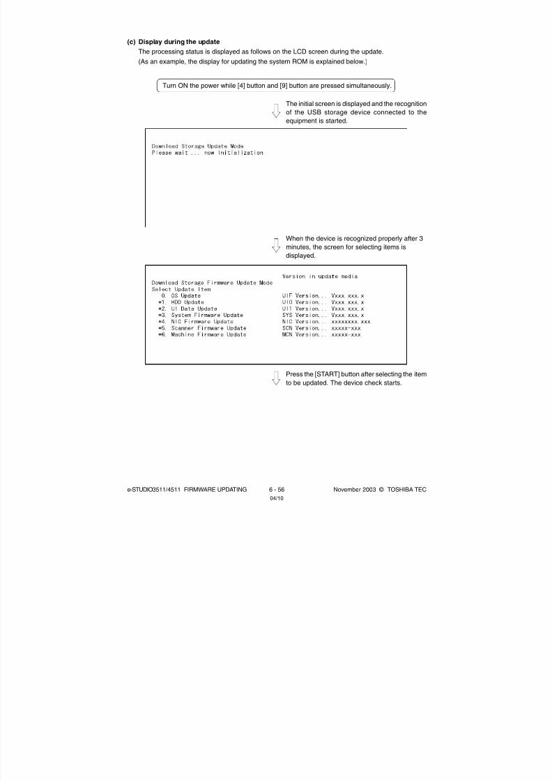
8/2/2019 ES-3511 Service Handbook
http://slidepdf.com/reader/full/es-3511-service-handbook 506/543
e-STUDIO3511/4511 FIRMWARE UPDATING 6 - 56 November 2003 © TOSHIBA TEC
The initial screen is displayed and the recognition
of the USB storage device connected to the
equipment is started.
Turn ON the power while [4] button and [9] button are pressed simultaneously.
When the device is recognized properly after 3
minutes, the screen for selecting items is
displayed.
Press the [START] button after selecting the item
to be updated. The device check starts.
04/10
(c) Display during the update
The processing status is displayed as follows on the LCD screen during the update.
(As an example, the display for updating the system ROM is explained below.)

8/2/2019 ES-3511 Service Handbook
http://slidepdf.com/reader/full/es-3511-service-handbook 507/543
November 2003 © TOSHIBA TEC 6 - 57 e-STUDIO3511/4511 FIRMWARE UPDATING
When the device check completes, copying the
data to the HDD starts.
Copied
File name of master dataTotal files
When all files have been copied, the backup of
RIP font starts.
When the backup of RIP font is completed, the
following screen is displayed. Updating the master
data is completed.

8/2/2019 ES-3511 Service Handbook
http://slidepdf.com/reader/full/es-3511-service-handbook 508/543
e-STUDIO3511/4511 FIRMWARE UPDATING 6 - 58 November 2003 © TOSHIBA TEC
Updating the system ROM starts subsequently.
The device check starts.
When the device check completes, copying the
data to the ROM of the equipment starts.
When copying the data completes, copying the
other data are implemented repeatedly.

8/2/2019 ES-3511 Service Handbook
http://slidepdf.com/reader/full/es-3511-service-handbook 509/543
November 2003 © TOSHIBA TEC 6 - 59 e-STUDIO3511/4511 FIRMWARE UPDATING
When copying all the data complete, the update
completes with the following screen.
* If the USB storage device is not recognized properly, the following message is displayed and the
update is interrupted.
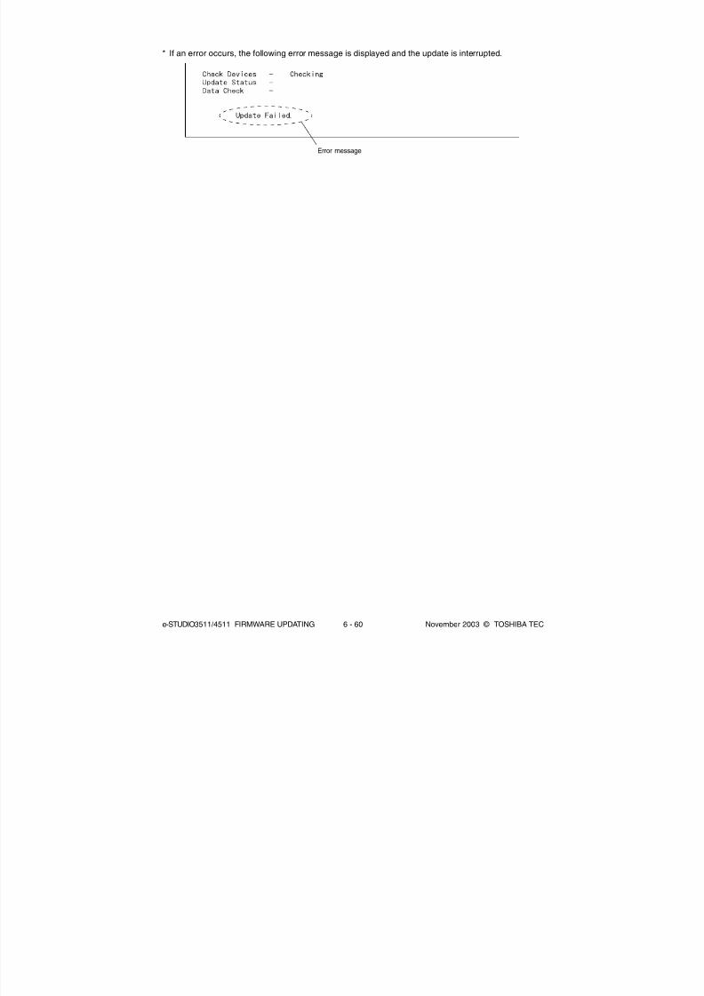
8/2/2019 ES-3511 Service Handbook
http://slidepdf.com/reader/full/es-3511-service-handbook 510/543
e-STUDIO3511/4511 FIRMWARE UPDATING 6 - 60 November 2003 © TOSHIBA TEC
Error message
* If an error occurs, the following error message is displayed and the update is interrupted.

8/2/2019 ES-3511 Service Handbook
http://slidepdf.com/reader/full/es-3511-service-handbook 511/543
November 2003 © TOSHIBA TEC 6 - 61 e-STUDIO3511/4511 FIRMWARE UPDATING
<Appendix> Assist Mode
This equipment has the Assist Mode to enable the following functions.
(1) NVRAM flag clearing (“Clear NvRAM flags.”)
Even if the firmware downloading has been completed normally, the Recovery Mode may
accidentally start up when the power is turned ON again. In this case, clear the NVRAM flags usedin the download process with this function.
(Normally, the flags are automatically cleared in the download process.)
Also in the case the Recovery Mode accidentally starts up after the replacement of NVRAM on the
SYS board, the flags are cleared with this function.
(2) Data storage partition formatting (“Format UID rom PRF PR2 SMS Partition.”)
When a defection occurs on the UI data, etc. which are stored in the HDD, the partition with the
stored UI data, etc. is formatted with this function.
(Do not use this function since it is not normally necessary.)
(3) HDD partition creation (“All Partition delete and create UID rom PRF PR2 SMS Partition.”)
When the HDD is replaced or UI data, etc. are downloaded using the FSMS or USB storage, it is
necessary to format a partition in the HDD before downloading. In this case, the partition is
created in the HDD with this function.
Notes:
1. When downloading with a download jig, it is not necessary to format a partition in advance.
2. Perform the HDD partition formatting only when a new HDD and scrambler board are installed
since all data in the current HDD are erased by this operation.
Operating Procedure of Assist Mode
(1) Turn ON the power while [3] button and [CLEAR] button are pressed simultaneously.
• The following screen is displayed.
(2) Select the item with the digital keys and press the [START] button.
04/10

8/2/2019 ES-3511 Service Handbook
http://slidepdf.com/reader/full/es-3511-service-handbook 512/543
e-STUDIO3511/4511 FIRMWARE UPDATING 6 - 62 November 2003 © TOSHIBA TEC

8/2/2019 ES-3511 Service Handbook
http://slidepdf.com/reader/full/es-3511-service-handbook 513/543
November 2003 © TOSHIBA TEC 7 - 1 e-STUDIO3511/4511 POWER SUPPLY UNIT
7. POWER SUPPLY UNIT
7.1 Output Channel
The followings are four output channels which are not linked with the door switch.
(1) +3.3V
+3.3VA : CN464 Pins 13, 14, 15 and 16Output to the SYS board
+3.3VB : CN464 Pins 19 and 20
Output to the SYS board
+3.3VB : CN466 Pin 3
Output to the LGC board
+3.3VB : CN467 Pins 17 and 18
Output to the SLG board
(2) +5.1V
+5.1VA : CN464 Pins 24 and 26
Output to the SYS board+5.1VB : CN464 Pin 25
Output to the SYS board
+5.1VB : CN466 Pin 1
Output to the LGC board, CCL board (via LGC board), PFP/LCF (via LGC
board), Bridge unit (via LGC board)
+5.1VB : CN467 Pins 5 and 6
Output to the RADF
+5.1VB : CN467 Pins 21 and 22
Output to the SLG board
+5.1VB : CN468 Pin 1Output to the finisher
+5.1VB : CN469 Pin 5
Output to the FIL board or FUS board
(3) +12V
+12VA : CN464 Pin 7
Output to the SYS board
+12VB : CN464 Pin 5
Output to the SYS board
+12VB : CN466 Pin 16 (*NAD/SAD/TWD models only)
Output to the LGC board(4) -12V
-12VA : CN464 Pin 9
Output to the SYS board
-12VB : CN464 Pin 3
Output to the SYS board

8/2/2019 ES-3511 Service Handbook
http://slidepdf.com/reader/full/es-3511-service-handbook 514/543
e-STUDIO3511/4511 POWER SUPPLY UNIT 7 - 2 November 2003 © TOSHIBA TEC
The followings are two output channels which are linked with the door switch.
(1) +5.1V
+5.1VD : CN466 Pins 11 and 12
Output to the LGC board
(2) +24V
+24VD1 : CN465 Pins 1 and 2
Output to the LGC board, CCL board (via LGC board), Bridge unit (via LGC
board)
+24VD1 : CN469 Pins 1 and 2
Output to the PFP/LCF
+24VD1 : CN470 Pin 1
Output to the power supply cooling fan
+24VD2 : CN465 Pins 5 and 6
Output to the DRV board
+24VD3 : CN467 Pins 1 and 2
Output to the RADF
+24VD4 : CN467 Pin 9
Output to the SDV board
+24VD4 : CN467 Pins 11 and 13
Output to the SLG board
+24VD5 : CN468 Pin 3
Output to the finisher
<<Output connector>>
Not linked with the door switch
CN464 For the SYS board
CN466 For the LGC board, FAX board, CCL board (via LGC board), PFP/LCF (via
LGC board), Bridge unit (via LGC board)
CN467 For the SLG board, RADF
CN468 For the finisher
CN469 For the FIL board / FUS board
Linked with the door switch
CN465 For the LGC board, DRV board, CCL board (via LGC board), Bridge unit
(via LGC board)
CN466 For the LGC board
CN467 For the SLG board, SDV board, RADF
CN468 For the finisher
CN469 For the PFP/LCF
CN470 For the power supply cooling fan

8/2/2019 ES-3511 Service Handbook
http://slidepdf.com/reader/full/es-3511-service-handbook 515/543
November 2003 © TOSHIBA TEC 7 - 3 e-STUDIO3511/4511 POWER SUPPLY UNIT
Voltage Board/Unit Part Fuse type
+24VD1 LGC Polygonal motor F3:8A (Semi time-lag)
Tray-up motor
ADU motor
Main motor
Developer motor
Transport motor
Drum cleaner brush motor
Transfer belt cleaner auger motor
Toner motor
Laser unit cooling fan
2nd transfer roller contact clutch
Bypass feed clutch
Registration clutch
Upper transport clutch (high speed)Upper transport clutch (low speed)
Lower transport clutch (high speed)
Lower transport clutch (low speed)
Upper drawer feed clutch
Lower drawer feed clutch
ADU clutch
Color developer toner supply clutch
Color developer drive clutch
Black developer drive clutch
Black developer lifting clutch
Transfer belt cleaner contact clutch
Bypass pickup solenoidImage quality sensor shutter solenoid
Color auto-toner sensor shutter solenoid
Discharge LED
Key copy counter / Copy key card
CCL Carge cleaner motor
Power supply Power supply cooling fan
PFP/LCF
Bridge unit
+24VD2 DRV Revolver motor F4:5A (Semi time-lag)
Exit motor
IH control board cooling fan
Ozone exhaust fan
Internal cooling fan
+24VD3 RADF F5:4A (Semi time-lag)
+24VD4 SLG Exposure lamp (lamp inverter) F6:4A (Semi time-lag)
CCD drive circuit (CCD board)
SLG board cooling fan
Scanner unit cooling fan
SDV Scan motor
+24VD5 Finisher F7:5A (Semi time-lag)
7.2 FuseWhen the power supply secondary fuse is blown out, confirm that there is no abnormally with each part
using the following table.
04/05

8/2/2019 ES-3511 Service Handbook
http://slidepdf.com/reader/full/es-3511-service-handbook 516/543
e-STUDIO3511/4511 POWER SUPPLY UNIT 7 - 4 November 2003 © TOSHIBA TEC
7.3 Configuration of Power Supply Unit
I H F 1
F 2
R e g .
R e g .
+ 2 4 V D 1 C N 4 7 0
P o w e r s u p p l y c o o l i n g f a n
+ 2 4 V D 4 C N 4 6 7
S L G b o a r d , S D V b o a r d
+ 5 . 1 V D
C N 4 6 6
L G C b o a r d
+ 3 . 3 V A
C N 4 6 4
S Y S b o a r d
+ 5 . 1 V A
C N 4 6 4
S Y S b o a r d
+ 1 2 V B
C N 4 6 6
L G C b o a r d
+ 1 2 V A
C N 4 6 4
S Y S b o a r d
+ 2 4 V D 5 C N 4 6 8
F i n i s h e r
+ 2 4 V D 3 C N 4 6 7
R A D F
+ 1 2 V B
C N 4 6 4
S Y S b o a r d
+ 2 4 V D 2 C N 4 6 5
D R V b o a r d
+ 3 . 3 V B
C N 4 6 4
S Y S b o a r d
+ 3 . 3 V B
C N 4 6 6
L G C b o a r d
+ 3 . 3 V B
C N 4 6 7
S L G b o a r d
+ 5 . 1 V B
C N 4 6 4
S Y S b o a r d
+ 5 . 1 V B
C N 4 6 6
L G C b o a r d , C C L b o a r d ( v i a L G C b o a r d ) ,
P F P / L C F ( v i a L G C b
o a r d ) ,
B r i d g e u n i t ( v i a L G C
b o a r d )
+ 5 . 1 V B
C N 4 6 7
S L G b o a r d , R A D F
+ 5 . 1 V B
C N 4 6 8
F i n i s h e r
+ 5 . 1 V B
C N 4 6 9
F I L b o a r d o r F U S b o
a r d
+ 2 4 V D 1 C N 4 6 5
L G C b o a r d , C C L b o a r d ( v i a L G C b o a r d ) ,
B r i d g e u n i t ( v i a L G C
b o a r d )
+ 2 4 V D 1 C N 4 6 9
P F P / L C F
- 1 2 V A
C N 4 6 4
S Y S b o a r d
A C M A I N
A C D O O
R
A C I N
C N 4 6 0 C N 4 6 0
L i v e
M a i n s w i t c h
D o o r s w i t c h
S w i t c h i n g
p o w e r s u p p l y
N o i s e
f i l t e r
N o i s e
f i l t e r
N o i s e
f i l t e r
N e u t r a l
B r e a k e r
- 1 2 V B
C N 4 6 4
S Y S b o a r d
F 5 F 7 F 4 F 3 F 6
F
I L b o a r d
F
U S b o a r d
* A S D / A U D / C
N D m o d e l s : S t a n d a r d
* M J D m o d e l : O p t i o n
* N A D / S A D / T W
D m o d e l s : S t a n d a r d
I C P 1

8/2/2019 ES-3511 Service Handbook
http://slidepdf.com/reader/full/es-3511-service-handbook 517/543
November 2003 © TOSHIBA TEC 8 - 1 e-STUDIO3511/4511 REMOTE SERVICE
8. REMOTE SERVICE
There are following functions as Remote Service.
(1) Auto Supply Order
Automatically orders the toner and used toner container by FAX or E-mail.
(2) Service Notification
Notifies the status of the equipment to the service technician by E-mail.
8.1 Auto Supply Order
8.1.1 Outline
Automatically orders the toner and used toner container.
(1) Placing an Order
There are two ways to place an order.
(1-1)FAX
Installation of the FAX board is required.
If the FAX board has not been installed, it is regarded as OFF setting.
(1-2) E-mail (E-mail body + TIFF image)
(2) Order Intervals
When the toner empty occurs, the number of occurrences is counted. And when it reaches the
specified number for CONDITION, the order is placed automatically.
With regard to the used toner container, it is done according to the number of the used toner
container full detection.
The number of the CONDITION can be set respectively for the toner and used toner container.
(3) If Order Failure Occurs
If some problems occur and the order cannot be placed after registering an order as a job, refer to
the standard countermeasure for the FAX/E-mail transmission failure.
04/05

8/2/2019 ES-3511 Service Handbook
http://slidepdf.com/reader/full/es-3511-service-handbook 518/543
e-STUDIO3511/4511 REMOTE SERVICE 8 - 2 November 2003 © TOSHIBA TEC
7
8.1.2 Setting Item
To enable Auto Supply Order, the following settings are required.
Note: When selecting E-mail to place an order, it is required that sending and receiving E-mails are
available. Confirm the details to the administrator.
(1) Self-diagnosis (08) Setting
As the default setting, the Auto Supply Order setting screen is not displayed on the touch panel.
To display it, switching the Valid/Invalid setting (08-765) is required.
0: Valid (FAX/Internet FAX)
1: Valid (FAX/Internet FAX/HTTP)*
2: Invalid (Default)
When changing the setting value from "2" (default) to "0", the Auto Supply Order setting screen is
displayed. (* HTTP has not been supported yet.)
(2) Touch Panel Setting
Each item is set from the Auto Supply Order screen on the touch panel.
Entering the password and customer information is required because the setting is made from the
ADMIN screen. Setting it with the administrator is a must.
(2-1)Basic setting
[ADMIN] > [SERVICE] > [SUPPLY ORDER SETUP] > [ORDER INFORMATION]
AUTO SUPPLY ORDER
FAX NUMBER
CUSTOMER
NAME
TEL NUMBER
ADDRESS
SUPPLIER
NAME
ADDRESS
SERVICE TECNICIAN
NUMBER
NAME
TEL NUMBER
Ordered by: [FAX], [MAIL], [HTTP] (*1)
FAX number of supplier (*2)
E-mail address of supplier (*3)
Customer information
Supplier information
Service technician information
*1 HTTP has not been supported yet.
*2 Even when "FAX" is selected, the order is not placed without entering the FAX number.
*3 Even when "MAIL" is selected, the order is not placed without entering the E-mail address.
04/05

8/2/2019 ES-3511 Service Handbook
http://slidepdf.com/reader/full/es-3511-service-handbook 519/543
November 2003 © TOSHIBA TEC 8 - 3 e-STUDIO3511/4511 REMOTE SERVICE
(2-2)Detailed setting for the order
[ADMIN] > [SERVICE] > [SUPPLY ORDER SETUP] > [TONER ORDERING]
***** TONER ORDER
PART NUMBER
CONDITIOIN
QUANTITY
AUTO ORDER
Order information (TONER /USED TONER CONTAINER)
Part number to be ordered
The number of conditions (*1)
The quantity to be ordered
ON/OFF setting of order for each part
*1 The order is placed when the number of replacement reaches the number specified for the CONDITION.
(2-3) FAX number of this equipment (common information)
[ADMIN] > [FAX] > [TERMINAL ID]
ID NAME
FAX NUMBER
ID name of this equipment
FAX number of this equipment
(2-4) E-mail information of this equipment (common information)
[ADMIN] > [E-MAIL]
FROM ADDRESS
FROM NAME
E-mail address of this equipment (*1)
E-mail username of this equipment
*1 When sending an E-mail, validity of the address is checked. If the address is invalid, it is not sent.
(3) Output of setting list of the Auto Supply Order Keying in the following buttons and keys prints the
setting list.
[USER FUNCTIONS] [USER] [LISTS] [*] [#] [*] [*] [3] [8] [START]

8/2/2019 ES-3511 Service Handbook
http://slidepdf.com/reader/full/es-3511-service-handbook 520/543
e-STUDIO3511/4511 REMOTE SERVICE 8 - 4 November 2003 © TOSHIBA TEC
7
8.1.3 Setting procedure
(1) Start up the self-diagnosis setting mode 08-765, and then change the setting value to "0".
(2) Turn the power OFF, and then ON.
(3) Press the [USER FUNCTIONS] button to enter the user function screen.
(4) Press the [ADMIN] button.
- When the Admin Password has been set, ADMINISTRATOR PASSWORD screen is displayed.
(5) Key in the Admin Password (6-digit), and then press the [ENTER] button.
* Confirm the password to the administrator.
(6) Press the [SERVICE] button in the ADMIN screen.

8/2/2019 ES-3511 Service Handbook
http://slidepdf.com/reader/full/es-3511-service-handbook 521/543
November 2003 © TOSHIBA TEC 8 - 5 e-STUDIO3511/4511 REMOTE SERVICE
(7) The SERVICE screen is displayed.
(8) Press the [SUPPLY ORDER SETUP] button.
(9) Press the [ORDER INFORMATION] button.
(10) The ORDER INFORMATION screen is displayed.

8/2/2019 ES-3511 Service Handbook
http://slidepdf.com/reader/full/es-3511-service-handbook 522/543
e-STUDIO3511/4511 REMOTE SERVICE 8 - 6 November 2003 © TOSHIBA TEC
7
(11) Press the buttons on the screen of ORDER INFORMATION to set the required item.
[FAX]/[MAIL] /[OFF] -- Select the [FAX] or the [MAIL] button for the transmitting way of order.
(HTTP has not been supported yet.)
[OFF]: Turn off the AUTO SUPPLY ORDER function.
[FAX NUMBER] ------- Input the FAX number of supplier.
(To transmit by FAX, the order cannot be placed automatically if you do not
input the number.)
[E-MAIL] ----------------- Input the E-mail address of supplier.
(To transmit by E-mail, the order cannot be placed automatically if you do
not input the address.)
(12) Press the [NEXT] button.
(Press the [ENTER] button to register, and then the screen returns to the (7) SERVICE screen.
Press the [CANCEL] button to cancel this register, and then the screen returns to the (7) SERVICE
screen.)
(13) The CUSTOMER/SUPPLIER screen is displayed.
(14) Press the buttons of the screen of CUSTOMER/SUPPLIER to set the required item.
CUSTOMER
[NAME] ------------- Input the name of customer.[TEL NUMBER]--- Input the telephone number of customer.
[E-MAIL] ------------ Input the E-mail address of customer.
[ADDRESS] ------- Input the address of customer.
SUPPLIER
[NAME] ------------- Input the name of supplier.
[ADDRESS] ------- Input the address of supplier.

8/2/2019 ES-3511 Service Handbook
http://slidepdf.com/reader/full/es-3511-service-handbook 523/543
November 2003 © TOSHIBA TEC 8 - 7 e-STUDIO3511/4511 REMOTE SERVICE
(15) Press the [NEXT] button.
(16) The SERVICE TECHNICIAN/ RESULT PRINTING screen is displayed.
(17) Press a button on the screen of SERVICE TECHNICIAN/ RESULT PRINTING to set the requireditem.
SERVICE TECHNICIAN
[NUMBER] --------- Input the number of SERVICE TECHNICIAN.
[NAME] ------------- Input the name of SERVICE TECHNICIAN.
[TEL NUMBER]--- Input the telephone number of SERVICE TECHNICIAN.
[E-MAIL] ------------ Input the E-mail address of SERVICE TECHNICIAN.
[DESCRIPTION] - Input the remarks if you want to register.
RESULT PRINTING
[OFF] / [ALWAYS] / [ON ERROR]
--- Whichever you press, the result list is printed. (These buttons have not been valid yet.)
(18) Press the [ENTER] button to register and complete the order information setting.

8/2/2019 ES-3511 Service Handbook
http://slidepdf.com/reader/full/es-3511-service-handbook 524/543
e-STUDIO3511/4511 REMOTE SERVICE 8 - 8 November 2003 © TOSHIBA TEC
7
(19) The SERVICE screen is returned.
(20) Press the [SUPPLY ORDER SETUP] button.
(21) Press the [TONER ORDERING] button.
(22) The TONER ORDERING screen is displayed.
(23) Press the [YELLOW(Y)] button. (Select the part to be ordered.)
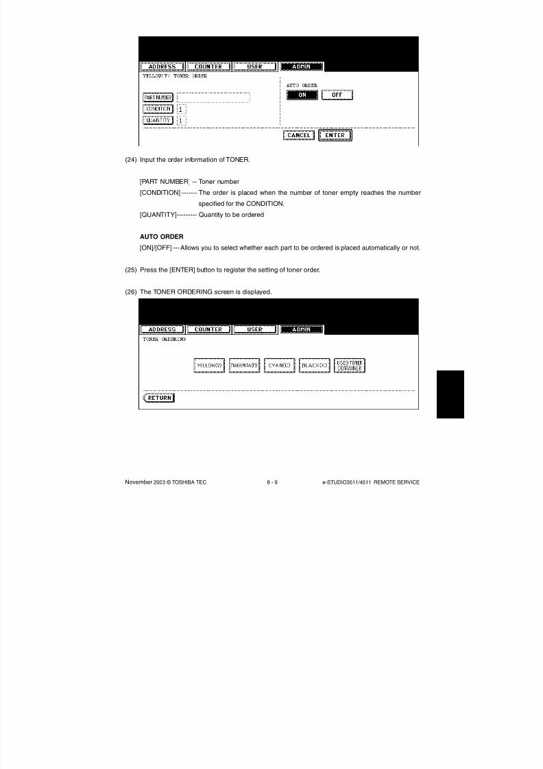
8/2/2019 ES-3511 Service Handbook
http://slidepdf.com/reader/full/es-3511-service-handbook 525/543
November 2003 © TOSHIBA TEC 8 - 9 e-STUDIO3511/4511 REMOTE SERVICE
(24) Input the order information of TONER.
[PART NUMBER] -- Toner number
[CONDITION] ------- The order is placed when the number of toner empty reaches the number
specified for the CONDITION.
[QUANTITY]--------- Quantity to be ordered
AUTO ORDER
[ON]/[OFF] ---Allows you to select whether each part to be ordered is placed automatically or not.
(25) Press the [ENTER] button to register the setting of toner order.
(26) The TONER ORDERING screen is displayed.

8/2/2019 ES-3511 Service Handbook
http://slidepdf.com/reader/full/es-3511-service-handbook 526/543
e-STUDIO3511/4511 REMOTE SERVICE 8 - 10 November 2003 © TOSHIBA TEC
7
(28) Press the [ENTER] button to register the order information.(29) The screen returns to the TONER ORDERING.
(30) Press the [USER FUNCTION] button to be switched from the ADMIN screen on touch panel and
returned to the BASIC screen, so that the setting of Auto Supply Order is finished.
Note: Auto Supply Order setting is also available from the following setting mode (08).
(27) Press the [MAGENTA(M)] / [CYAN(C)] / [BLACK(K)] / [USED TONER CONTAINER] button, and
then input the order information in the same way.
The transmitting way of order
[FAX]/[MAIL] /[OFF]
SUPPLIER
[FAX NUMBER]
SUPPLIER
[E-MAIL]
CUSTOMER
[NAME]
CUSTOMER
[TEL NUMBER]
CUSTOMER
[E-MAIL]
CUSTOMER
[ADDRESS]
SUPPLIER
[NAME]
SUPPLIER
[ADDRESS]
732
733
734
738
739
740
741
746
747
0: Ordered by FAX
1: Ordered by E-mail
2: Ordered by HTTP
3: OFF
Maximum 32 digits
Maximum 192 letters
Maximum 50 letters
Maximum 32 digits
Maximum 192 letters
Maximum 100 letters
Maximum 50 letters
Maximum 100 letters
Items 08 code Contents
04/09

8/2/2019 ES-3511 Service Handbook
http://slidepdf.com/reader/full/es-3511-service-handbook 527/543
November 2003 © TOSHIBA TEC 8 - 11 e-STUDIO3511/4511 REMOTE SERVICE
Items 08 code Contents
SERVICE TECHNICIAN
[NUMBER]
SERVICE TECHNICIAN
[NAME]
SERVICE TECHNICIAN
[TEL NUMBER]
SERVICE TECHNICIAN
[E-MAIL]
Remarks
[DESCRIPTION]
RESULT PRINTING
[OFF] / [ALWAYS] / [ON ERROR]
YELLOW(Y) TONER
[PART NUMBER]YELLOW(Y) TONER
[CONDITION]
YELLOW(Y) TONER
[QUANTITY]
MAGENTA(M) TONER
[PART NUMBER]
MAGENTA(M) TONER
[CONDITION]
MAGENTA(M) TONER
[QUANTITY]CYAN(C) TONER
[PART NUMBER]
CYAN(C) TONER
[CONDITION]
CYAN(C) TONER
[QUANTITY]
BLACK(K) TONER
[PART NUMBER]
BLACK(K) TONER
[CONDITION]BLACK(K) TONER
[QUANTITY]
USED TONER CONTAINER
[PART NUMBER]
USED TONER CONTAINER
[CONDITION]
USED TONER CONTAINER
[QUANTITY]
742
743
744
745
748
764
755
757
756
752
754
753
749
751
750
758
760
759
761
763
762
Maximum 5 digits
Maximum 50 letters
Maximum 32 digits
Maximum 192 letters
Maximum 128 letters
0: OFF
1: Always
2: ON Error
Maximum 20 digits
1-99
1-99
Maximum 20 digits
1-99
1-99
Maximum 20 digits
1-99
1-99
Maximum 20 digits
1-99
1-99
Maximum 20 digits
1-99
1-99

8/2/2019 ES-3511 Service Handbook
http://slidepdf.com/reader/full/es-3511-service-handbook 528/543
e-STUDIO3511/4511 REMOTE SERVICE 8 - 12 November 2003 © TOSHIBA TEC
7
8.1.4 Order Sheet Format
The sample of order sheet is as follows.
(1) FAX (This format is the same as that of TIFF image attached E-mail.)
*1 Part not to be ordered is not output. (Less space between the lines)
DATE & TIME :99-99-'99 99:99
CUSTOMER NUMBER :XXX
CUSTOMER NAME :XXXXXXXXXXXXXXXXXXXXXXXXXXXXXXXXXXX
CUSTOMER ADDRESS :XXXXXXXXXXXXXXXXXXXXXXXXXXXXXXXXXXX
CUSTOMER TEL NUMBER :XXXXXXXXXXXXXXXXXXXXXXXXXXXXXXXXXXX
CUSTOMER E-MAIL ADDRESS :XXXXXXXXXXXXXXXXXXXXXXXXXXXXXXXXXXX
SERVICE TECHNICIAN TEL NUMBER :XXXXXXXXXXXXXXXXXXXXXXXXXXXXXXXXXXX
SERVICE TECHNICIAN E-MAIL :XXXXXXXXXXXXXXXXXXXXXXXXXXXXXXXXXXX
SUPPLIER NAME :XXXXXXXXXXXXXXXXXXXXXXXXXXXXXXXXXXX
SUPPLIER ADDRESS :XXXXXXXXXXXXXXXXXXXXXXXXXXXXXXXXXXX
PART NUMBER QUANTITY
TONER CARTRIDGE
CYAN : XXXXXXXXXXXX 99
MAGENTA : XXXXXXXXXXXX 99
YELLOW : XXXXXXXXXXXX 99
BLACK : XXXXXXXXXXXX 99
USED TONER CONTAINER : XXXXXXXXXXXX 99
DESCRIPTION AREA ..............................................
.................................................................
DEVICE DESCRIPTION :XXXXXXXXXXXXXXXXXXXXXXX
SERIAL NUMBER :XXXXXXXXXXXXXXXXXXXXXXX
DEVICE FAX NUMBER :XXXXXXXXXXXXXXXXXXXXXXX
DEVICE E-MAIL ADDRESS :XXXXXXXXXXXXXXXXXXXXXXX
TOTAL BLACK TWIN COLOR FULL COLOR
PRINT COUNTER 999999999 999999999 999999999 999999999
SCAN COUNTER 999999999 999999999 999999999 999999999
(*1)
(2) E-MAIL (TIFF image attached with the E-mail is the same format with that of the FAX order sheet.)
SUBJECT: SUPPLY ORDER REQUEST
*1 Part not to be ordered is not output. (Less space between the lines)
Date&Time: '03-09-12 00:17
Customer Number: S01 MachineName: TOSHIBA e-STUDIO4511
SerialNumber: 1234567890
Device FAX Number:Device Email: [email protected]
OrderInformation:
YELLOW PartNumber: YELLOW-03 Quantity:17
CounterInformation:
PrintCounter(Small) FullColor: 0 TwinColor: 0 Black: 141
PrintCounter(Large) FullColor: 0 TwinColor: 0 Black: 0
ScanCounter FullColor: 0 TwinColor: 0 Black: 7
(*1)

8/2/2019 ES-3511 Service Handbook
http://slidepdf.com/reader/full/es-3511-service-handbook 529/543
November 2003 © TOSHIBA TEC 8 - 13 e-STUDIO3511/4511 REMOTE SERVICE
(3) Result list
ORDER XXXXXXXXX
DATE & TIME :99-99-'99 99:99
CUSTOMER NUMBER :XXX
CUSTOMER NAME :XXXXXXXXXXXXXXXXXXXXXXXXXXXXXXXXXXX
CUSTOMER ADDRESS :XXXXXXXXXXXXXXXXXXXXXXXXXXXXXXXXXXX
CUSTOMER TEL NUMBER :XXXXXXXXXXXXXXXXXXXXXXXXXXXXXXXXXXX
CUSTOMER E-MAIL ADDRESS :XXXXXXXXXXXXXXXXXXXXXXXXXXXXXXXXXXX
SERVICE TECHNICIAN
TEL NUMBER :XXXXXXXXXXXXXXXXXXXXXXXXXXXXXXXXXXX
SERVICE TECHNICIAN E-MAIL :XXXXXXXXXXXXXXXXXXXXXXXXXXXXXXXXXXX
SUPPLIER NAME :XXXXXXXXXXXXXXXXXXXXXXXXXXXXXXXXXXX
SUPPLIER ADDRESS :XXXXXXXXXXXXXXXXXXXXXXXXXXXXXXXXXXX
PART NUMBER QUANTITY
TONER CARTRIDGE
CYAN : XXXXXXXXXXXX 99
MAGENTA : XXXXXXXXXXXX 99
YELLOW : XXXXXXXXXXXX 99
BLACK : XXXXXXXXXXXX 99
USED TONER CONTAINER : XXXXXXXXXXXX 99
DESCRIPTION AREA ..............................................
.................................................................
DEVICE DESCRIPTION :XXXXXXXXXXXXXXXXXXXXXXX
SERIAL NUMBER :XXXXXXXXXXXXXXXXXXXXXXX
DEVICE FAX NUMBER :XXXXXXXXXXXXXXXXXXXXXXX
DEVICE E-MAIL ADDRESS :XXXXXXXXXXXXXXXXXXXXXXX
TOTAL BLACK TWIN COLOR FULL COLOR
PRINT COUNTER 999999999 999999999 999999999 999999999
SCAN COUNTER 999999999 999999999 999999999 999999999
(*1)
*1 Part not to be ordered is not output. (Less space between the lines)

8/2/2019 ES-3511 Service Handbook
http://slidepdf.com/reader/full/es-3511-service-handbook 530/543
e-STUDIO3511/4511 REMOTE SERVICE 8 - 14 November 2003 © TOSHIBA TEC
7
8.2 Service Notification
8.2.1 Outline
This function automatically notifies the status of the equipment to the service technician by E-mail. The
following three are the items to be notified.
- Total Counter Transmit
When this function is effective, it notifies each counter information periodically (on the set date and
time every month).
- Service Call Transmit
When this function is effective, it notifies the corresponding error code and such at a service call error.
- PM Counter Transmit
When this function is effective, it notifies that the PM timing has come when the present PM count has
reached to its setting value, or the present PM driving count has reached to its setting value.
8.2.2 Setting
8.2.2.1 Preparation
Note: When using this function, it is required that sending and receiving E-mails are available. Confirm
the details to the administrator.
The screen to set this function is not displayed at the default setting.
Set this screen to be displayed with the following code (08).
08-774 Setting of notification display
0: Invalid (Default)
1: Valid
04/05

8/2/2019 ES-3511 Service Handbook
http://slidepdf.com/reader/full/es-3511-service-handbook 531/543
November 2003 © TOSHIBA TEC 8 - 15 e-STUDIO3511/4511 REMOTE SERVICE
8.2.2.2 Setting procedure
1) Press the [USER FUNCTIONS] button and select the [ADMIN] button. Then enter the password
and press the [ENTER] button.
• Confirm the password to the administrator.
2) Press the [SERVICE] button.
3) Press the [SERVICE NOTIFICATION] button.
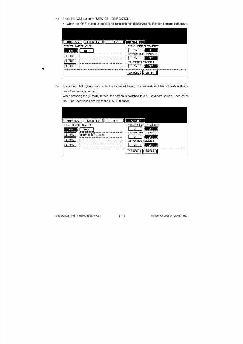
8/2/2019 ES-3511 Service Handbook
http://slidepdf.com/reader/full/es-3511-service-handbook 532/543
e-STUDIO3511/4511 REMOTE SERVICE 8 - 16 November 2003 © TOSHIBA TEC
7
4) Press the [ON] button in "SERVICE NOTIFICATION".
• When the [OFF] button is pressed, all functions related Service Notification become ineffective.
5) Press the [E-MAIL] button and enter the E-mail address of the destination of this notification. (Maxi-
mum 3 addresses are set.)
When pressing the [E-MAIL] button, the screen is switched to a full keyboard screen. Then enter
the E-mail addresses and press the [ENTER] button.

8/2/2019 ES-3511 Service Handbook
http://slidepdf.com/reader/full/es-3511-service-handbook 533/543
November 2003 © TOSHIBA TEC 8 - 17 e-STUDIO3511/4511 REMOTE SERVICE
6) Press the [ON] button to notify or [OFF] button not to notify of each item.
When the Total Count Transmit is set ON, the screen to set the notification date is displayed. Then
set the notification date with the following procedure. (The information is notified on the set date
and time every month.)
6-1) Key in the date (acceptable values: 1-31) in "Date" and press the [SET] button. (Correct the value
by pressing the [CLEAR] button if the [SET] button is not yet pressed. Correct the value by pressing
the [RESET] button to move the cursor back to the digit to be corrected if the [SET] button is already
pressed.)
6-2) Key in the time (acceptable values: 00:00-23:59) in "Time".
Key in the time in the hour column of "Time", press the [SET] button, key in the time in the minute
column of "Time" and press the [SET] button. (Correct the value by pressing the [CLEAR] button if
the [SET] button is not yet pressed. Correct the value by pressing the [RESET] button to move the
cursor back to the digit to be corrected if the [SET] button is already pressed.)
6-3) Press the [ENTER] button to set all. The display returns to the screen at procedure 5).
7) Press the [ENTER] button. The setting completes.

8/2/2019 ES-3511 Service Handbook
http://slidepdf.com/reader/full/es-3511-service-handbook 534/543
e-STUDIO3511/4511 REMOTE SERVICE 8 - 18 November 2003 © TOSHIBA TEC
7
Service Notification setting
E-mail address 1
E-mail address 2
E-mail address 3
Total Counter Transmit setting
Total counter transmission interval
setting (days)
Total counter transmission interval
setting
(Hour/Hour/Minute/Minute)
Service Call Transmit setting
PM Counter Transmit setting
767
768
777
778
769
770
776
775
771
0: OFF (Invalid) 1: ON (Valid)
Maximum 192 letters
Maximum 192 letters
Maximum 192 letters
0: OFF (Invalid) 1: ON (Valid)
1 to 31 days
00:00-23:59
0: OFF (Invalid) 1: ON (Valid)
0: OFF (Invalid) 1: ON (Valid)
Items 08 code Contents
Note:
Service Notification setting is also available from the following setting mode (08).

8/2/2019 ES-3511 Service Handbook
http://slidepdf.com/reader/full/es-3511-service-handbook 535/543
November 2003 © TOSHIBA TEC 8 - 19 e-STUDIO3511/4511 REMOTE SERVICE
8.2.3 Items to be notified
The items of E-mail to be notified are shown below.
1) Total Counter Transmit / PM Counter Transmit (XML file attached to E-mail has also the same
format.)
Subject: Counter Notification
(In case of the PM Counter Transmit, it is shown as "Periodical Maintenance Notification".)
3
7
8
11
12
13
15
1617
18
19
20
21
22
23
2
4
1
56
9
10
14
24
25
26
27
28
Date : 10/20/2003 13:47Machine Model : TOSHIBA e-STUDIO4511SerialNumber : 1234567890Total Counter : 00004787 ChargeCounterFormat:
LargeSizeChargeCount 1LargeSizeChargePaperDefinition 1
PMCounterFormat:
LargeSizePMCount 1LargeSizePMPaperDefinition 0
Charge Counter:
Large Small
<Print Counter>Full Color -------------------------------------
Copy 00000000 00000000Print 00000000 00000000
Twin Color ------------------------------------
Copy 00000000 00000000Black ------------------------------------------
Copy 00000000 00000000Print 00000000 00000000List 00000000 00000000
FAX 00000000 00000000
<Scan Counter>Full Color -------------------------------------
Copy Scan 00000000 00000000Net Scan 00000000 00000000Twin Color ------------------------------------
Copy Scan 00000000 00000000Black ------------------------------------------
Copy Scan 00000000 00000000
FAX Scan 00000000 00000000Net Scan 00000000 00000000
<FAX Counter>Transmit 00000000 00000000
Receive 00000000 00000000 Periodical Maintenance Counter:
Set PM 00150000
Current PM 00004787Set PMTime 00000000CurrentPMTime 00000000
Printer Error History:
Date Time ErrorCode-----------------------------------------------10/18/2003 16:44 F11010/15/2003 22:28 F110
10/15/2003 22:23 F11009/15/2003 22:23 F11008/25/2003 11:12 F110
(*1)
04/10

8/2/2019 ES-3511 Service Handbook
http://slidepdf.com/reader/full/es-3511-service-handbook 536/543
e-STUDIO3511/4511 REMOTE SERVICE 8 - 20 November 2003 © TOSHIBA TEC
7
1 Date
2 Machine model name
3 Serial number
4 Total counter value
5 Count setting of large-sized paper (Fee charging system counter)
6 Definition setting of large-sized paper (Fee charging system counter)
7 Count setting of large-sized paper (PM)
8 Definition setting of large-sized paper (PM)
9 Number of output pages in the Copier Function (FULL COLOR)
10 Number of output pages in the Printer Function (FULL COLOR)
11 Number of output pages in the Copier Function (TWIN COLOR)
12 Number of output pages in the Copier Function (BLACK)
13 Number of output pages in the Printer Function (BLACK)
14 Number of output pages at the List Print Mode (BLACK)
15 Number of output pages in the FAX Function (BLACK)
16 Number of scanning pages in the Copier Function (FULL COLOR)
17 Number of scanning pages in the Network Scanning Function (FULL COLOR)
18 Number of scanning pages in the Copier Function (TWIN COLOR)
19 Number of scanning pages in the Copier Function (BLACK)
20 Number of scanning pages in the FAX Function (BLACK)
21 Number of scanning pages in the Network Scanning Function (BLACK)
22 Number of transmitted pages in the FAX Function (BLACK)
23 Number of received pages in the FAX Function (BLACK)
24 PM count setting value
25 PM count present value
26 PM driving count setting value
27 PM driving count present value
28 History of error
*1 The latest 20 errors are displayed.
04/10

8/2/2019 ES-3511 Service Handbook
http://slidepdf.com/reader/full/es-3511-service-handbook 537/543
November 2003 © TOSHIBA TEC 8 - 21 e-STUDIO3511/4511 REMOTE SERVICE
45
6
1
2 3
7
8
Date: 10/20/2003 13:47
Machine Name: e-STUDIO4511 SerialNumber:1234567890
Function: PrintSeverity: Error
ErrorCode: XXXX
Message:
XXXXXXXXXXXXXXXXXXXXXXXXXXXXXXXXXXXXXXXXXXXXXXXXXXXX
Printer Error History:
Date Time ErrorCode
------------------------------------------
10/18/2003 16:44 F110
10/15/2003 22:28 F110
10/15/2003 22:23 F110
09/15/2003 22:23 F110
08/25/2003 11:12 F110
(*1)
1 Date (When an error occurs)
2 Machine model name
3 Serial number
4 Function: Fixed at "Print"
5 Severity: Fixed at "Error"6 Error code
7 Error message: The content of error is displayed.
8 History of error
*1 The latest 20 errors are displayed.
2) Service Call Transmit
Subject: Service Call Notification
04/10
8/2/2019 ES-3511 Service Handbook
http://slidepdf.com/reader/full/es-3511-service-handbook 538/543
e-STUDIO3511/4511 REMOTE SERVICE 8 - 22 November 2003 © TOSHIBA TEC
7

8/2/2019 ES-3511 Service Handbook
http://slidepdf.com/reader/full/es-3511-service-handbook 539/543
November 2003 © TOSHIBA TEC 9 - 1 e-STUDIO3511/4511 WIRE HARNESS CONNECTION DIAGRAMS
9. WIRE HARNESS CONNECTION DIAGRAMS
9.1 AC Wire Harness
1 2
1 2
1 2
1 2
R Y
P W A - F - F I L
S C A N N E R
T H E R M O - S C N - D H
1
1
2
2
S C N - L - D H
S C N - R - D H
1
2
3
1
2
3
J 6 5 2
J 6 5 7
J 4 3 3
J 5 9 5
J 6 5 6
J 6 6 2
J 6 5 5
J 6 5 3
J 6 2 2
J 4 3 1
J 4 3 2
J 6 0
J 6 3
J 6 4
J 6 1
J 6 2
A C ( N : S C N )
S G
+ 5 . 1
V B
A C ( N )
A C ( L )
A C ( L : S C N )
T H E R M O - D R M - D H
T H E R M O - F S R
+ 5 . 1 V B
S G
+ 5 . 1
V B
S G
I H - C O I L
P S - A C C
F U S E R
P W A - F - F U S
M A I N - S W
( M A I N - S W I T C H )
N S - F I L T E R
( N O I S E F I L T E R )
B R E A K
E R
I N L E T
( A C I N ) M
A I N
G N D F
G
C O V - I N T L C K - S W
A S D , A
U D , S
A D ,
T W D , C
N D M O D E L S :
S T A N D A R D
N A D , M
J D M O D E L S :
O P T I O N
2 1
D R M - N
( D C L I N E )
D R M - L
A C ( N : M A I N )
A C ( N : O U T )
A C ( G N D )
A C ( L : O U T )
A C ( L : M A I N )
A C ( N : M A I N )
A C ( L : M A I N )
A C ( N )
A C ( L )
A C ( N : M A I N )
A C ( L : M A I N )
A C ( N : D O O R )
A C ( L : D O O R )
A C - I N - Y H M ( N )
A C - I N - Y H M ( N )
A C - I N - Y H M ( N )
A C - I N
( L )
J 6 5 0
+ 5 V
A C A D A P T E R
D R M - D H
P S - I H
A C - D C
D C
N F
A C - D C
D C
N F
4 5 6 1
1
2
2
3 3
4 2
3 1
2 4
1 2 3 6
6 5 4 3 2 1
1 4
1 3
2 1
3 4
R Y
J 4 6 9
J 6 4 7
J 4 6 0
J 5 4 6
J 6 4 3
J 6 4 2
J 6 4 4
J 6 4 4
C
N 4 5 3
F 1
F 2
C
N 4 5 2
C N 4 5 1
C N 4 5 0
C
N 4 5 4
3
A B
1
3
2
2 1
3 1
3
2
2 1
3
A
G
F
B C
4
1 2
N F
N G N D
L
( O P T I O N )
W I R E L E S S L A N
( C O V E R O
P E N I N G / C L O S I N G )
I N T E R L O C K S W I T C H
D H - S C N - L
D H - S C N - N
A S D , A
U D , C
N D M O D E L S :
S T A N D A R D
M J D M O D E L :
O P
T I O N
S A D , T W D N A D , M
O D E L S :
S T A N D
A R D
1
2
3
J 6 5 0
J 4 9 4 1 2 3 4
J 4 9 3
A C ( N )
A C ( L )
S G
1 3 2
J 4 9 5
+ 5 . 1
V B
3 4
A C ( N )
A C ( L )
2 1
J 4 3 3
J 4 3 2
4 5 6 1 2 3 3 2 1
L O A D
8/2/2019 ES-3511 Service Handbook
http://slidepdf.com/reader/full/es-3511-service-handbook 540/543
e-STUDIO3511/4511 WIRE HARNESS CONNECTION DIAGRAMS 9 - 2 November 2003 © TOSHIBA TEC
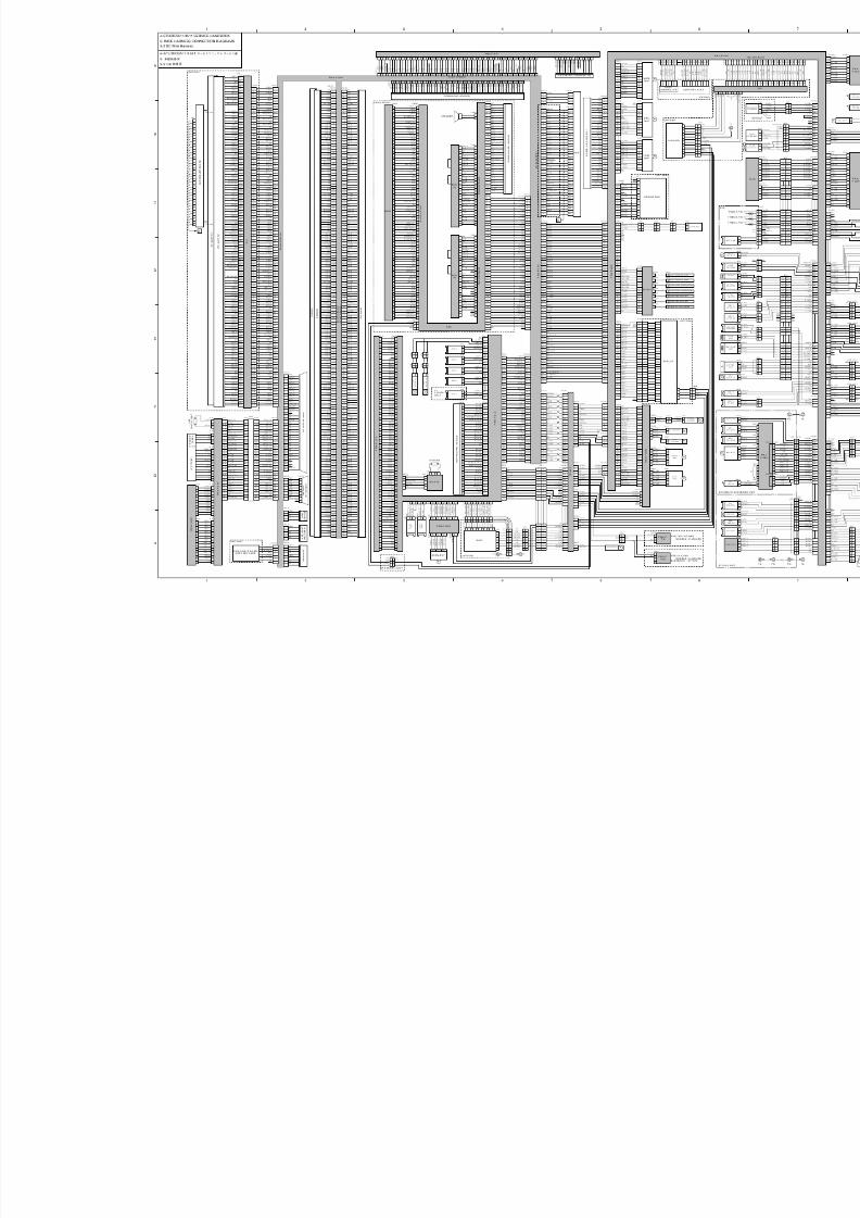
8/2/2019 ES-3511 Service Handbook
http://slidepdf.com/reader/full/es-3511-service-handbook 541/543

8/2/2019 ES-3511 Service Handbook
http://slidepdf.com/reader/full/es-3511-service-handbook 542/543

8/2/2019 ES-3511 Service Handbook
http://slidepdf.com/reader/full/es-3511-service-handbook 543/543