Embed Size (px)
Citation preview

SCHAKO | Ferdinand Schad KG Phone +49 (0) 7463-980-0 Steigstraße 25-27 Fax +49 (0) 7463-980-200 D-78600 Kolbingen www.SCHAKO.de | [email protected]
USABILITY CERTIFICATES
• Performance Reliability Certificate 0761 – CPR – 0506
• Declaration of Performance DoP-ERK-SO-2016-07-01
CLASSIFICATION AND STANDARDS
• Classification according to EN 13501-4 is EI 90 (vedw, how i↔o) S 1000 C10000 MA multi, depending on the mounting situation
• Product standard EN 12101-8
• Test standards EN 1366-2 and EN 1366-10
PERFORMANCE DATA
• For ventilating smoke in smoke extraction systems and for providing the necessary sup-ply air within the smoke extraction installa-tion
• For use in solid walls, ceilings and smoke ex-traction lines
• For automatic (AA) or manual (MA) triggering SPECIAL FEATURES
• Thermally insulated actuator housing • The installation position does not depend on
the air flow direction or the position of the damper blade axle
• Reversible OPEN/CLOSED actuator with 24 V AC/DC or 230 V AC s upply voltage
• Optional actuator with Powerline SLC bus technology possible. In conjunction with additional communication devices it is possible to retrieve further data, for example indication of end position, keep-ing timeframe (<60 s) or torque monitoring.
ERK-SOSmoke extraction damper
TECHNICAL DOCUMENTATION with installation, mounting and operating instructions

Smoke extraction damper ERK-SO TECHNICAL DOCUMENTATION Table of Contents |
Construction subject to change No return possible Version: 2017-11-28 | Page 2
TABLE OF CONTENTS
Description ..................................................................... 3 Models and dimensions ................................................. 4 Installation details ......................................................... 8
Installation in solid walls ............................................ 8
Installation directly on solid walls............................ 14
Installation in solid ceilings ...................................... 17
Vertical installation on solid ceilings ........................ 20
Connection to smoke extraction ducts ........................ 21 Connection options on or in horizontal smoke extraction ducts ....................................................... 21
Connection options on horizontal smoke extraction ducts in accordance with EN 12101-7, tested according to EN 1366-8 ........................................... 22
Connection instructions for smoke extraction duct made of sheet metal ................................................ 23
Suspensions and weights ............................................. 24 Minimum distances and projecting ends..................... 28 Technical data .............................................................. 29 Design data .................................................................. 30 Accessories .................................................................. 31 Technical data - Actuators ........................................... 32 Add-on parts ................................................................ 34 Legend ......................................................................... 35 Order code ................................................................... 36 Specification texts ........................................................ 37 CE marking ................................................................... 38 Service ......................................................................... 39 Sample of functional test protocol .............................. 40 Foreign branch offices ................................................. 42 Lists .............................................................................. 43

Smoke extraction damper ERK-SO TECHNICAL DOCUMENTATION Description |
Construction subject to change No return possible Version: 2017-11-28 | Page 3
DESCRIPTION
The smoke extraction damper ERK-SO conforms to EN 12101-8, EN 13501-4, EN 1366-2 and EN 1366-10. The ERK-SO has been tested according to EN 1366-2 and EN 1366-10 in ac-cordance with the Declaration of Performance No. DoP-ERK-SO-2016-07-01. It is in possession of the Performance Relia-bility Certificate according to EU-BauPVO 0761 - CPR - 0506. Its classification according to EN 13501-4, depending on the mounting situation is: EI 90 (vedw, how i↔o) S 1000 C10000 MA multi.
Smoke extraction dampers are intended for ventilating smoke in smoke extraction systems and for providing necessary sup-ply air within the smoke extraction installation. The smoke extraction dampers are driven by a reversible OPEN / CLOSE actuator with 24 V AC/DC or 230 V AC supply voltage. It is located in a thermally insulated actuator housing to ensure correct opening and closing of the smoke extrac-tion damper under fire conditions.
Optionally, the ERK-SO can be equipped with the EK12 (SEL 1.90 SLC, 24 V AC/DC) / EK14 (EK12 + SPMa-1SR) actuator. Each smoke extraction damper is connected only with one two-wire line by means of the SLC technology, thus allowing detection or reporting of short-circuit or line break of the SLC lines through constant monitoring. The function of the actua-tor EK12 is only active when an additional required communi-cation device (e.g. EK14 = EK12 + SPMa-1SR) is connected.
Suitable communication devices, for example SPMa1SR or SPLM-4S 0SD Mod. allow retrieving data, such as indication of end position, keeping timeframe (<60 s) or torque monitor-ing.
For use in solid walls and ceilings for supplying air or ventilat-ing smoke, also in combination with smoke extraction lines in compliance with EN 121017 which have been tested accord-ing to EN 13668 or EN 13669.
The national standards and guidelines must be observed in connection with this technical documentation, installation, mounting and operating instructions.
For functional test, service, retrofitting, etc., inspection open-ings must be provided on site in suspended ceilings, shaft walls, connected ventilation ducts etc., if necessary. They must be built in sufficient numbers and size and must not im-pair the functioning of the smoke extraction dampers.
o Housing and damper blade made of silicate struc-tural panel,optionally (at an extra charge):• SR internal impregnation (ex works only) for
protection against aggressive mediao With circumferential stop bar seals to meet the cold
and hot leakage requirementso Horizontal or vertical position of the damper blade
axle (axle made of stainless steel)o The installation position does not depend on the air
flow directiono The connection to smoke extraction ducts made of
wall boards is done according to inspected duct-spe-cific constructions. The connection to the testedsheet steel lines or flexible spigots is carried out viathe profile connection frame type PAR. Smoke ex-traction systems with mechanical vents require a se-cure power supply in case of fire. A power supplyabove the public supply, through a power producinginstallation (replacement power) depends on eachcase of public and legal requirements.
ATTENTION
Building systems have to be arranged, installed and main-tained in such a way that they prevent fire and propagation of fire and smoke (fire propagation) and allow evacuation of persons and animals as well as efficient fire extinguishing work.

Smoke extraction damper ERK-SO TECHNICAL DOCUMENTATION Models and dimensions |
Construction subject to change No return possible Version: 2017-11-28 | Page 4
MODELS AND DIMENSIONS
Dimensions
1-- ERK-SO housing (consisting of 2 x 25 mm silicate structural
panels) 2-- Profile connection frame PAR (optional) 3-- Damper blade (consisting of 3 x 20 mm silicate structural
panels) 4-- Stop bar (40 x 20 mm with milled recess for the seal) 5-- Actuator housing incl. cover 6-- Actuator 7-- Stop bar seal (to meet the cold and hot leakage require-
ments)
Min. damper length
Detail A
Figure 1 - Dimensions ERK-SO
Smoke extraction damper ERK-SO TECHNICAL DOCUMENTATION Models and dimensions |
Construction subject to change No return possible Version: 2017-11-28 | Page 5
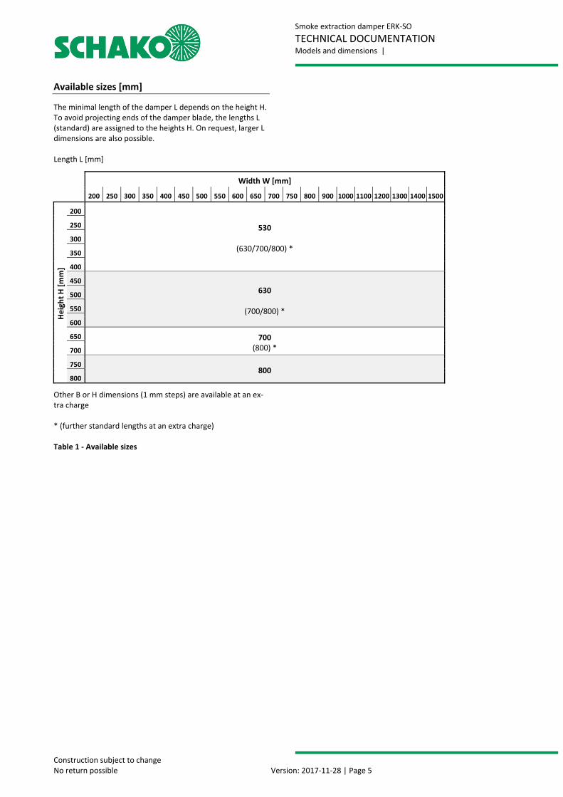
Available sizes [mm]
The minimal length of the damper L depends on the height H. To avoid projecting ends of the damper blade, the lengths L (standard) are assigned to the heights H. On request, larger L dimensions are also possible. Length L [mm]
Other B or H dimensions (1 mm steps) are available at an ex-tra charge * (further standard lengths at an extra charge) Table 1 - Available sizes
Width W [mm]
200 250 300 350 400 450 500 550 600 650 700 750 800 900 1000 1100 1200 1300 1400 1500
Heig
ht H
[mm
]
200
530
(630/700/800) *
250
300
350
400
450 630
(700/800) *
500
550
600
650 700 (800) * 700
750 800
800

Smoke extraction damper ERK-SO TECHNICAL DOCUMENTATION Models and dimensions |
Construction subject to change No return possible Version: 2017-11-28 | Page 6
ERK-SO shown without profile connection frame PAR
Table 2 - Dimensions of the actuator housing 1 -- Housing of ERK-SO (shown without profile connection
frame PAR) 27-- Actuator 21/22/23 -- Actuator housing (consisting of the actuator cas-
ing and the cover with seal made of Insulfrax paper) 19/20/24 -- Fastening set for the inspection of the actuator
(by loosening the hexagon screws M6 x 100 mm)
H L a (BS) b (MS) ** 200 ≤ H ≤ 400 530 65 75 401 ≤ H ≤ 565 630 65 175 566 ≤ H ≤ 634 630 50 190 635 ≤ H ≤ 711 700 85 255 712 ≤ H ≤ 800 800 135 275
Detail B of the actuator housing Standard motor installation is horizontal as shown, vertical design is also possible on request
Min. damper length
Figure 2 - Actuator housing
Picture showing an enlargement of the actuator enclosure (ex-works only) * The enlargement (in 25 mm steps) depends on
the existing requirement
** A housing extension of the b side (MS) is only possible by a dimen-sion resulting in a maximum total housing length (L) of 800 mm (in exceptional cases 1000 mm).

Smoke extraction damper ERK-SO TECHNICAL DOCUMENTATION Models and dimensions |
Construction subject to change No return possible Version: 2017-11-28 | Page 7
Use
The smoke extraction damper type ERK-SO can be fitted as shown in the following table.
1) when installed next to each other 2) when installed on top of each other 3) in connection with mounting brackets WE-S and on-
site suspensions and horizontal damper blade axle Table 3 - Usability General information
o During mounting or installation, there is a risk of in-juries. To avoid injuries, personal protective equip-ment (PPE) must be worn.
o Smoke extraction dampers must be installed such that external forces do not impair their functioning. During mounting it may be required to provide rein-forcements for the housing or the like. The require-ment of statically load-bearing lintels may have to be taken into consideration.
o Improper transport/handling may result in dam-age/functional impairment. In addition to that, the film of the transport packaging must be removed and the delivery inspected for completeness.
o In storage, smoke extraction dampers must be pro-tected from dust, dirt, moisture and the effects of extreme temperatures. They must not be exposed to direct effects of the weather.
4) in connection with ceiling frame DR-S 5) in connection with on-site suspensions 6) in connection with on-site fastening frames and suspen-
sions
o The smoke extraction dampers must be protected from dirt and damage. After installation is complete, any dirt must be removed immediately.
o Enough space must be provided for installation, mor-tar lining, etc.
o Carry out a functional check of the smoke extraction damper before and after mounting and ensure ready access.
o Electrical installations or work on electrical compo-nents may only be carried out by skilled electricians. The supply voltage must be switched off when per-forming this work.
o Always check whether the housing needs to be ex-tended on the b side (MS) for the corresponding in-stallation situations (e.g. the thickness of the sup-porting structure and a possible connection to the smoke extraction duct must be considered).
Use Instal-lation Material/Model
Mini-mum
thickness [mm]
Minimum distance of two ERK-SO
from one another [mm]
Fire resistance class
For no-tes, see
page
WAL
L
solid Apparent density
≥ 450 kg/m³
in
for example, concrete, masonry ac-cording to EN 1996 or DIN 1053; solid plaster wall boards according to EN 12859 or DIN 18163
100 0 (4)1)
2002)
EI 90(vew,i↔o)S 1000 C10000 MA multi
8
on3)
for example, concrete, masonry ac-cording to EN 1996 or DIN 1053; solid plaster wall boards according to EN 12859 or DIN 18163
100 200 EI 90(vew,i↔o)S 1000 C10000 MA multi
14
CEIL
ING
solid Apparent density
≥ 650±200 kg/m³
in3) for example, concrete, aerated con-crete 150 200 EI 90(how,i↔o)S
1000 C10000 MA multi 17
to4) for example, concrete, aerated con-crete 150 200 EI 90(how,i↔o)S
1000 C10000 MA multi 20
SMO
KE E
XTRA
CTIO
N
DUCT
horizontal Apparent density
≥ 520 kg/m³
in5) in accordance with EN 12101-7, tested according to EN 1366-8 35 200 EI 90(ved,i↔o)S
1000 C10000 MA multi 21
on5) in accordance with EN 12101-7, tested according to EN 1366-8 35 200 EI 90(ved,i↔o)S
1000 C10000 MA multi 21
to6) in accordance with EN 12101-7, tested according to EN 1366-8 35 200 EI 90(ved,i↔o)S
1000 C10000 MA multi 22

Smoke extraction damper ERK-SO TECHNICAL DOCUMENTATION Installation details |
Construction subject to change No return possible Version: 2017-11-28 | Page 8
INSTALLATION DETAILS
Installation in solid walls
o Installation in solid walls (shaft walls, shafts, ducts and fire walls) made of, for example, concrete, ma-sonry according to EN 1996 or DIN 1053; solid plas-ter wall boards according to EN 12859 or DIN 18163; apparent density ≥ 450 kg/m³ and wall thickness W ≥ 100 mm.
o Distance to the bearing adjacent components (wall / solid ceiling) is minimum 75 mm.
Wet installation o Circumferential gaps "s" must be completely filled
with mortar of category M2.5 to M15 in accordance with EN 998-2 (previously: MG II to III according to DIN 1053) or fire protection mortar of suitable grades. The minimum gap size smin is 10 mm; maxi-mum gap size smax ≤ 60 mm. The mortar lining must be executed such that it is permanent and, for exam-ple no mortar breaks occur. The information given by the mortar manufacturer must be observed.
o If the smoke extraction damper is installed during the construction of the wall, the gaps "s" can be omitted. The mortar bed depth must be executed in the minimum wall thickness and may not be less than 100 mm. When performing a mortar lining or direct installation, make sure that the housing is not pressed toward the inside (reinforcement). If neces-sary, a statically active lintel must be provided.
o In case of dry installation next to each other, the smoke extraction dampers (max. 2 pieces) can be in-stalled without clearance.
o In case of wet installation on top of each other, the distance between the smoke extraction dampers must be at least 200 mm.
Dry installation
o Circumferential gaps "s" must be completely filled with mineral wool (non-flammable EN 13501-1, ap-parent/packing density approx. 100 kg/m³, melting point ≥ 1000 °C) and secured with a circumferential frame made of silicate structural panels. The mini-mum gap size smin is 10 mm; maximum gap size smax ≤ 20 mm.
o In case of dry installation, the distance of the smoke extraction dampers to one another must be at least 200 mm.
Figure 3 - Opening dimensions of the solid wall * Please note Fill circumferential gaps "s" approx. 15 ±5 mm with mineral wool (in case of wall installation only) (non-flammable EN 13501-1, apparent/packing density approx. 100 kg/m³, melt-ing point ≥ 1000 °C) or mortar (at least 10 to ≤ 60 mm) of cat-egory M2.5 to M15 in accordance with EN 998-2 (previously: MG II to III according to DIN 1053) or fire protection mortar of suitable grades.
Figure 4 - Air flow direction
Opening dimension
Ope
ning
dim
en-
Plung

Smoke extraction damper ERK-SO TECHNICAL DOCUMENTATION Installation details |
Construction subject to change No return possible Version: 2017-11-28 | Page 9
Please note If H ≤ 400 mm, the housing must be extended for this arrangement. If the wall thickness is > 100 mm, always check whether the housing needs to be extended on the b side (MS) - see page 6 Table 2 - (the available wall thickness and a possible connection to the smoke extraction duct must be taken into account).
Wet installation Dry installation
Detail A Mortar of category M2.5 to M15 in accordance with EN 998-2 (previously: MG II to III according to DIN 1053) or fire protection mortar of suitable grades. Gap ≥ 10 ≤ 60 mm
* the dimensions of the threaded rods and the U-steel can be found on pages 24 - 27.
Suspension *
Detail B Mineral wool A1, melting point ≥ 1000 °C / gap 15±5 mm
In the lower gap, place (only in case of filling with mineral wool) 2 spacers made of sili-cate structural panel (di-mens. W = 20 mm x L = 50 mm x H = gap height 10 – 20 mm) each approx. 50 mm from the outer housing of the ERK-SO.
Wall
Wall
Circumferential frame 40 x 40 made of silicate structural panel at a distance of 150 mm screwed to the ERK-SO hous-ing with Spax screws 5 x 80 and glued with water glass glue (SBK 2000).
Detail C
Profile connection frame PAR
Installation example with profile connection frame PAR when con-nected with a continuation smoke extraction duct made of sheet metal for use within the fire area from which smoke is to be ex-tracted.
Figure 5 - Installation in solid walls

Smoke extraction damper ERK-SO TECHNICAL DOCUMENTATION Installation details |
Construction subject to change No return possible Version: 2017-11-28 | Page 10
Installation positions
Arrangement of the ERK-SO when installed next to each other without clearance With this arrangement, an additional accessory package is required for the connection to the smoke extraction dampers as a function of the dimension
vertical position of the damper blade axle (independent of the actuator position)
horizontal position of the damper blade axle
vertical position of the damper blade axle
horizontal position of the damper blade axle
Arrangement of the ERK-SO when installed on top of each other with a clearance of 200 m
Figure 6 - Minimum distances of the ERK-SO in solid wall

Smoke extraction damper ERK-SO TECHNICAL DOCUMENTATION Installation details |
Construction subject to change No return possible Version: 2017-11-28 | Page 11
Please note If H ≤ 400 mm, the housing must be extended for this arrangement. If ERK-SO are arranged next to each other with horizontal axis, the heads of hexagon screws must be countersunk. The ERK-SO must always be filled with mortar. If the wall thickness is > 100 mm, always check whether the housing needs to be extended on the b side (MS) - see page 6 Table 2 - (the available wall thickness and a possible connection to the smoke extraction duct must be taken into account).
Mortar of category M2.5 to M15 in ac-cordance with EN 998-2 (previously: MG II to III according to DIN 1053) or fire pro-tection mortar of suit-able grades. Gap ≥ 10 ≤ 60 mm
U-steel
B ve
rtic
al a
xle
1500
Mortar of category M2.5 to M15 according to EN 998-2 (previously: MG II to III ac-cording to DIN 1053) or fire protec-tion mortar of suitable grades. Gap ≥ 10 ≤ 60 mm
Connection of the two smoke extraction dampers (on site) with hexagon head screws with shaft similar to DIN 931 (ISO 4014) M8 x 100 mm U-washers according to DIN 125 (ISO 7089) int. Ø 8.4 / out. Ø 16 / 1.6 mm thick Drive-in nut M8 with 4 prongs (galvanized steel) d2 = 22, d3 = 10, h = 15
SECTION A-A DETAIL B
Insulfrax paper 5 mm thick (glued ex works to the ERK-SO over the entire surface with water glass glue.)
ERK-SO housing
Bores Ø 10 mm
Figure 7 - Installation in solid wall without clearance
Installation of the ERK-SO directly next to one another in solid walls (additional accessory package required)
Plunge View
View

Smoke extraction damper ERK-SO TECHNICAL DOCUMENTATION Installation details |
Construction subject to change No return possible Version: 2017-11-28 | Page 12
Accessory package for installation next to each other without clearance The suitable accessory package for installation of the ERK-SO without clearance next to each other must be determined as a function of the dimension and the position of dampler blade axle as specified in the tables below (Table 4or Table 5).
The accessory package consists of the corresponding amount of Insulfrax paper, water glass glue and the number of re-quired screw connections. Except for the application of the Insulfrax paper ex works (ap-plied using water glass glue), the work must be carried out on site.
When ordering, please specify connection side (B or H side).
Vertical position of the damper blade axle For the connection on the side (vertical position of the damper blade axle), the position of the actuators (operation) must be additionally specified.
Table 4 - Accessory packages for vertical damper blade axle po-sition
200 225 250 275 300 325 350 375 400 450 500 550 600 650 700 750 800 900 1000 1100 1200 1300 1400 1500200 I I I I I I I I I I I I I II II II II III III III III III III III225 I I I I I I I I I I I I I II II II II III III III III III III III250 I I I I I I I I I I I I I II II II II III III III III III III III275 I I I I I I I I I I I I I II II II II III III III III III III III300 I I I I I I I I I I I I I II II II II III III III III III III III325 I I I I I I I I I I I I I II II II II III III III III III III III350 I I I I I I I I I I I I I II II II II III III III III III III III375 I I I I I I I I I I I I I II II II II III III III III III III III400 I I I I I I I I I I I I I II II II II III III III III III III III440 I I I I I I I I I I I I I II II II II III III III III III III III450 I I I I I I I I I I I I I II II II II III III III III III III III500 I I I I I I I I I I I I I II II II II III III III III III III III550 I I I I I I I I I I I I I II II II II III III III III III III III600 I I I I I I I I I I I I I II II II II III III III III III III III650 II II II II II II II II II II II II II II II II II III III III III III III III700 II II II II II II II II II II II II II II II II II III III III III III III III750 II II II II II II II II II II II II II II II II II III III III III III III III800 II II II II II II II II II II II II II II II II II III III III III III III III
Heig
ht H
Width W
Accessory package I I
Accessory package II II
Accessory package III III

Smoke extraction damper ERK-SO TECHNICAL DOCUMENTATION Installation details |
Construction subject to change No return possible Version: 2017-11-28 | Page 13
Horizontal position of the damper blade axle For the connection on the H sides (horizontal position of the damper blade axle), the heads of the hexagon screws must be countersunk.
Table 5 - Accessory packages for horizontal damper blade axle position
200 225 250 275 300 325 350 375 400 450 500 550 600 650 700 750 800 900 1000 1100 1200 1300 1400 1500200 I I I I I I I I I I I I I II II II II II II II II II II II225 I I I I I I I I I I I I I II II II II II II II II II II II250 I I I I I I I I I I I I I II II II II II II II II II II II275 I I I I I I I I I I I I I II II II II II II II II II II II300 I I I I I I I I I I I I I II II II II II II II II II II II325 I I I I I I I I I I I I I II II II II II II II II II II II350 I I I I I I I I I I I I I II II II II II II II II II II II375 I I I I I I I I I I I I I II II II II II II II II II II II400 I I I I I I I I I I I I I II II II II II II II II II II II440 I I I I I I I I I I I I I II II II II II II II II II II II450 I I I I I I I I I I I I I II II II II II II II II II II II500 I I I I I I I I I I I I I II II II II II II II II II II II550 I I I I I I I I I I I I I II II II II II II II II II II II600 I I I I I I I I I I I I I II II II II II II II II II II II650 II II II II II II II II II II II II II II II II II II II II II II II II700 II II II II II II II II II II II II II II II II II II II II II II II II750 II II II II II II II II II II II II II II II II II II II II II II II II800 II II II II II II II II II II II II II II II II II II II II II II II II
Heig
ht H
Width W
Accessory package I I
Accessory package II II

Smoke extraction damper ERK-SO TECHNICAL DOCUMENTATION Installation details |
Construction subject to change No return possible Version: 2017-11-28 | Page 14
Installation directly on solid walls
o Installation in solid walls (shaft walls, shafts, ducts and fire walls) made of, for example, concrete, ma-sonry according to EN 1996 or DIN 1053; solid plas-ter wall boards according to EN 12859 or DIN 18163; apparent density ≥ 450 kg/m³ and wall thickness W ≥ 100 mm.
o Installation with horizontal damper blade axle only o The distance to load-bearing, adjacent components
(wall / solid ceiling) is (due to the construction) at least 100 mm.
o Additional suspension required with U-steel (pole brace).
Wal
l ope
ning
=
Housing length
Threaded rod (s. p. 16 - Table 8)
Smoke extraction duct made of silicate structural panel (in accordance with EN 12101-7, tested according to EN 1366-8) or smoke extraction duct made of sheet steel tested according to EN 13669
U-steel (U50/38) Suspension (Dimensioning according to EN 1366-1 with the max. suspension length of 1500 mm, for distance between solid ceiling and pole brace support, see pages 24 - 27
Aerated concrete wall
WE-S with bonded Insulfrax paper
Figure 8 - Installation on solid walls

Smoke extraction damper ERK-SO TECHNICAL DOCUMENTATION Installation details |
Construction subject to change No return possible Version: 2017-11-28 | Page 15
Picture showing mounting bracket WE-S on ERK-SO and solid wall
1 -- Housing made of silicate structural panels (t=50 mm) I -- Mounting bracket type WE-S
(galvanised steel 100 x 100 x 160 mm long) II -- Seal (bonded) made of Insulfrax paper
(100 x 160 x 5 mm dick) III -- Hexagon head screw to DIN 931 (e.g. M 10 x 30 mm) IV -- U-washers DIN 125-A V -- Fire protection dowels, e.g. type KMU-F10 (with rein-
forced concrete walls only) or threaded rods (on site) VI -- Seal bonded to ERK-SO (front side to the wall
made of Insulfrax paper 50 x 5 mm thick) Number and arrangement of mounting brackets WE-S
Proposed installation ERK-SO in front of the concrete wall with suspension. The brackets are fastened to the reinforced con-crete wall as a function of the dimension (s. + ) with, for example, fire protection dowels type KMU-F10 . On solid walls (e.g. aerated concrete), continuous threaded rods must be used for fastening. Damper length L depends on W x H.
Please note The exact arrangement and number of mounting brackets WE-S and U-steel are defined by SCHAKO according to the ERK-SO dimensions and can be found in the following tables!
U-washer DIN 9021, e.g. (10.5/30/2.5 mm
2x threaded rod, e.g. M10
Nut, e.g. M10
Insulfrax paper 5 mm thick
Hexagon head screw M10x55
Figure 9 - Fastening WE-S on ERK-SO and solid wall
U-washer (11/30/1.5 mm thick)
M10 H16x25 drive-in nut

Smoke extraction damper ERK-SO TECHNICAL DOCUMENTATION Installation details |
Construction subject to change No return possible Version: 2017-11-28 | Page 16
Number of mounting brackets type WE-S
Table 6 - Number of mounting brackets WE-S for installation on solid wall Number with specification of the arrangement and wall fastening
Total number of WE-S (as a function of dimensions) 2 2 4 5 4 5 6 7
Positioning of the WE-S brack-ets
Top B side 1 1 2 3 1 2 2 3
Bottom B side 1 1 2 2 1 1 2 2
Left H side - - - - 1 1 1 1
Right H side - - - - 1 1 1 1
On-site wall fastening per WE-S bracket with 2 units ...... M12 M10 M10 M10 M12 M10 M10 M10
Table 7 - Arrangement of WE-S and wall fastening for installation on solid wall Dimensioning of the suspension (threaded rods) for U-steel
Table 8 - Suspension (threaded rods) for U-steel for installation on solid wall
Länge L
200 225 250 275 300 325 350 375 400 450 500 550 600 650 700 750 800 900 1000 1100 1200 1300 1400 1500 [mm]200 M8 M8 M8 M8 M8 M8 M8 M8 M8 M8 M8 M8 M8 M8 M8 M8 M10 M10 M10 M10 M10 M10 M10 M12225 M8 M8 M8 M8 M8 M8 M8 M8 M8 M8 M8 M8 M8 M8 M8 M10 M10 M10 M10 M10 M10 M10 M12 M12250 M8 M8 M8 M8 M8 M8 M8 M8 M8 M8 M8 M8 M8 M8 M8 M10 M10 M10 M10 M10 M10 M10 M12 M12275 M8 M8 M8 M8 M8 M8 M8 M8 M8 M8 M8 M8 M8 M8 M10 M10 M10 M10 M10 M10 M10 M12 M12 M12300 M8 M8 M8 M8 M8 M8 M8 M8 M8 M8 M8 M8 M8 M8 M10 M10 M10 M10 M10 M10 M10 M12 M12 M12325 M8 M8 M8 M8 M8 M8 M8 M8 M8 M8 M8 M8 M8 M10 M10 M10 M10 M10 M10 M10 M12 M12 M12 M12350 M8 M8 M8 M8 M8 M8 M8 M8 M8 M8 M8 M8 M8 M10 M10 M10 M10 M10 M10 M10 M12 M12 M12 M12375 M8 M8 M8 M8 M8 M8 M8 M8 M8 M8 M8 M10 M10 M10 M10 M10 M10 M10 M10 M12 M12 M12 M12 M12400 M8 M8 M8 M8 M8 M8 M8 M8 M8 M8 M8 M10 M10 M10 M10 M10 M10 M10 M10 M12 M12 M12 M12 M12450 M8 M8 M8 M8 M8 M8 M8 M10 M10 M10 M10 M10 M10 M10 M10 M10 M10 M12 M12 M12 M12 M12 M12 M12500 M8 M8 M8 M8 M8 M10 M10 M10 M10 M10 M10 M10 M10 M10 M10 M10 M12 M12 M12 M12 M12 M12 M12 M14550 M8 M8 M8 M10 M10 M10 M10 M10 M10 M10 M10 M10 M10 M10 M10 M12 M12 M12 M12 M12 M12 M12 M14 M14600 M8 M10 M10 M10 M10 M10 M10 M10 M10 M10 M10 M10 M10 M10 M12 M12 M12 M12 M12 M12 M12 M14 M14 M14650 M8 M10 M10 M10 M10 M10 M10 M10 M10 M10 M10 M10 M12 M12 M12 M12 M12 M12 M12 M12 M14 M14 M14 M14700 M10 M10 M10 M10 M10 M10 M10 M10 M10 M10 M10 M12 M12 M12 M12 M12 M12 M12 M12 M14 M14 M14 M14 M14750 M10 M10 M10 M10 M10 M10 M10 M12 M12 M12 M12 M12 M12 M12 M12 M12 M12 M12 M14 M14 M14 M14 M14 M14800 M10 M10 M10 M10 M10 M12 M12 M12 M12 M12 M12 M12 M12 M12 M12 M12 M12 M14 M14 M14 M14 M14 M14 M16
530
Höhe
H [m
m]
630
700
800
Breite B [mm]Width W [mm]
Heig
ht H
[mm
]
Length L
[mm]
Länge L
200 225 250 275 300 325 350 375 400 450 500 550 600 650 700 750 800 900 1000 1100 1200 1300 1400 1500 [mm]200 2 2 2 2 2 2 2 2 2 4 4 4 4 4 4 4 4 4 4 4 4 5 5 5225 2 2 2 2 2 2 2 2 2 4 4 4 4 4 4 4 4 4 4 4 4 5 5 5250 2 2 2 2 2 2 2 2 2 4 4 4 4 4 4 4 4 4 4 4 4 5 5 5275 2 2 2 2 2 2 2 2 2 4 4 4 4 4 4 4 4 4 4 4 4 5 5 5300 2 2 2 2 2 2 2 2 2 4 4 4 4 4 4 4 4 4 4 4 4 5 5 5325 2 2 2 2 2 2 2 2 2 4 4 4 4 4 4 4 4 4 4 4 4 5 5 5350 2 2 2 2 2 2 2 2 2 4 4 4 4 4 4 4 4 4 4 4 4 5 5 5375 2 2 2 2 2 2 2 2 2 4 4 4 4 4 4 4 4 4 4 4 4 5 5 5400 2 2 2 2 2 2 2 2 2 4 4 4 4 4 4 4 4 4 4 4 4 5 5 5450 4 5 5 5 5 5 5 5 5 6 6 6 6 6 6 6 6 6 7 7 7 7 7 7500 4 5 5 5 5 5 5 5 5 6 6 6 6 6 6 6 6 6 7 7 7 7 7 7550 4 5 5 5 5 5 5 5 5 6 6 6 6 6 6 6 6 6 7 7 7 7 7 7600 4 5 5 5 5 5 5 5 5 6 6 6 6 6 6 6 6 6 7 7 7 7 7 7650 4 5 5 5 5 5 5 5 5 6 6 6 6 6 6 6 6 6 7 7 7 7 7 7700 4 5 5 5 5 5 5 5 5 6 6 6 6 6 6 6 6 6 7 7 7 7 7 7750 4 6 6 6 6 6 6 6 6 6 6 6 6 7 7 7 7 7 7 7 7 7 7 7800 4 6 6 6 6 6 6 6 6 6 6 6 6 7 7 7 7 7 7 7 7 7 7 7
Höhe
H [m
m]
530
630
700
800
Breite B [mm]Width W [mm]Length
L [mm]
Heig
ht H
[mm
]

Smoke extraction damper ERK-SO TECHNICAL DOCUMENTATION Installation details |
Construction subject to change No return possible Version: 2017-11-28 | Page 17
Installation in solid ceilings
o Installation in solid ceilings made, for example, of concrete, aerated concrete, apparent density ≥ 650±200 kg/m³ and ceiling thickness D ≥ 150 mm.
o Installation with complete mortar lining: Circumferential gaps "s" must be completely filled with mortar of category M2.5 to M15 in accordance with EN 998-2 (previously: MG II to III according to DIN 1053) or fire protection mortar of suitable grades. The minimum gap size smin is 10 mm; maxi-mum gap size smax ≤ 60 mm. The mortar lining must be executed such that it is permanent and, for example no mortar breaks oc-cur. The information given by the mortar manufac-turer must be observed. If the smoke extraction damper is installed during the construction of the ceiling, the gaps "s" can be omitted. The mortar bed depth must be executed in the minimum ceiling thickness and may not be less than 150 mm. When performing a mortar lining or direct installation, make sure that the housing is not pressed toward the inside (reinforcement). For load carrying when installed in solid ceilings (ver-tical/suspended), additional mounting brackets WE-S are required.
o The distance of the smoke extraction dampers to one another must be at least 200 mm.
o The distance to load-bearing, adjacent components (wall) is at least 75 mm.
Figure 10 - Opening dimensions of the solid ceiling * Please note Circumferential gaps "s" (at least 10 to ≤ 60 mm) must be filled with mortar of category M2.5 to EN 998-2 (previously: MG II to III according to DIN 1053) or fire protection mortar of suitable grades.
Opening dimension
Ope
ning
dim
ensio
n

Smoke extraction damper ERK-SO TECHNICAL DOCUMENTATION Installation details |
Construction subject to change No return possible Version: 2017-11-28 | Page 18
Suspended/vertical installation in solid ceilings
For the correct number and positioning of the mounting brack-ets, the installation situation ((suspended/vertical) must be specified when ordering.
suspended
vertical in
Wet installation Mortar gap ≥ 10 ≤ 60 mm
Wet installation Mortar gap ≥ 10 ≤ 60 mm
Mortar of category M2.5 to M15 in ac-cordance with EN 998-2 (previously: MG II to III according to DIN 1053) or fire protection mortar of suitable grades.
Mortar of category M2.5 to M15 in accord-ance with EN 998-2 (previously: MG II to III according to DIN 1053) or fire protection mortar of suitable grades.
Figure 11 - Installation in solid ceilings
Remarks: When installed suspended in solid ceilings, the mount-ing brackets WE-S must usually be positioned and mounted on site. Otherwise, if installed ex works, the ERK-SO could not be inserted into the ceiling recess.

Smoke extraction damper ERK-SO TECHNICAL DOCUMENTATION Installation details |
Construction subject to change No return possible Version: 2017-11-28 | Page 19
Example of load carrying in solid ceilings
Top view
Number of mounting brackets WE-S for installation in solid ceiling
Table 9 - Number of mounting brackets WE-S for installation in solid ceiling
Please note The exact arrangement and number of mounting brackets WE-S are defined by SCHAKO according to the ERK-SO dimensions! (s. table below). When installing in solid ceilings, always check whether the housing needs to be extended on the b side (MS) - see page 6 Table 2 - [the available ceiling thickness, the WE-S brackets for load carrying, especially for suspended installation (opera-tion from below), and a possible connection to the smoke extraction duct must be taken into account].
Fastening the WE-S on ERK-SO with 2 x M10 ERK-SO housing
/ Depending on the type of ceiling, fixed with, for example, Spax / concrete
Figure 12 - Arrangement of WE-S when installed in solid ceilings
200 225 250 275 300 325 350 375 400 450 500 550 600 650 700 750 800 900 1000 1100 1200 1300 1400 1500200 2 2 2 2 2 2 2 2 2 2 2 2 4 4 4 4 4 4 4 4 4 4 4 4225 2 2 2 2 2 2 2 2 2 2 2 2 4 4 4 4 4 4 4 4 4 4 4 4250 2 2 2 2 2 2 2 2 2 2 2 2 4 4 4 4 4 4 4 4 4 4 4 4275 2 2 2 2 2 2 2 2 2 2 2 2 4 4 4 4 4 4 4 4 4 4 4 4300 2 2 2 2 2 2 2 2 2 2 2 2 4 4 4 4 4 4 4 4 4 4 4 4325 2 2 2 2 2 2 2 2 2 2 2 2 4 4 4 4 4 4 4 4 4 4 4 4350 2 2 2 2 2 2 2 2 2 2 2 2 4 4 4 4 4 4 4 4 4 4 4 4375 2 2 2 2 2 2 2 2 2 2 2 2 4 4 4 4 4 4 4 4 4 4 4 4400 2 2 2 2 2 2 2 2 2 2 2 2 4 4 4 4 4 4 4 4 4 4 4 4440 2 2 2 2 2 2 2 2 2 2 2 2 4 4 4 4 4 4 4 4 4 4 4 4450 2 2 2 2 2 2 2 2 2 2 2 2 4 4 4 4 4 4 4 4 4 4 4 4500 2 2 2 2 2 2 2 2 2 2 2 2 4 4 4 4 4 4 4 4 4 4 4 4550 2 2 2 2 2 2 2 2 2 2 2 2 4 4 4 4 4 4 4 4 4 4 4 4600 4 4 4 4 4 4 4 4 4 4 4 4 4 4 4 4 4 4 4 4 4 4 4 4650 4 4 4 4 4 4 4 4 4 4 4 4 4 4 4 4 4 4 4 4 4 4 4 4700 4 4 4 4 4 4 4 4 4 4 4 4 4 4 4 4 4 4 4 4 4 4 4 4750 4 4 4 4 4 4 4 4 4 4 4 4 4 4 4 4 4 4 4 4 4 4 4 4800 4 4 4 4 4 4 4 4 4 4 4 4 4 4 4 4 4 4 4 4 4 4 4 4
Width W [mm]
Heig
ht H
[mm
]

Smoke extraction damper ERK-SO TECHNICAL DOCUMENTATION Installation details |
Construction subject to change No return possible Version: 2017-11-28 | Page 20
Figure 13 - Vertical installation on solid ceiling
Vertical installation on solid ceilings
o Vertical installation on solid ceilings made, for exam-ple, of concrete, aerated concrete, apparent density ≥ 650±200 kg/m³ and ceiling thickness D ≥ 150 mm.
o The required ceiling breakthrough must correspond to the nominal dimensions (WxH) of the ERK-SO. The installation is possible only in connection with the ceiling frame DR-S (accessories).
o The distance of the smoke extraction dampers to one another must be at least 200 mm.
o The distance to load-bearing, adjacent components (wall) is (due to the construction) at least 100 mm.
Mounting information
o Adjust connection between ERK-SO and ceiling with water glass glue (SBK 2000).
o Additional mounting brackets made of steel (2 pieces) are required up to dimensions W and H = 500 mm (included in accessories of ceiling frame DR-S).
Ceiling breakthrough =
Fastening the ceiling frame DR-S on aerated concrete ceilings Hexagon head screw M8 x 70 U-washer DIN 125 M8 Dowel FTP M8
Fastening the ceiling frame DR-S on reinforced concrete ceilings Concrete screw FBS 8 x 70 Mudguard washer galvanised steel i. Ø 10.5 / o. Ø 30 / 1.25 mm thick
Detail B
Insulfrax paper 5 mm
Dry wall screw 4x40 mm, on site
Steel dowel M8 and screw M8, on site
Mounting brackets made of steel required up to dimensions W and H = 500 m.
Ceiling frame DR-S

Smoke extraction damper ERK-SO TECHNICAL DOCUMENTATION Connection to smoke extraction ducts |
Construction subject to change No return possible Version: 2017-11-28 | Page 21
CONNECTION TO SMOKE EXTRACTION DUCTS
Connection options on or in horizontal smoke extraction ducts in accordance with EN 12101-7, tested according to EN 1366-
Connection to horizontal smoke extraction duct 8
Smoke extraction ducts (to EN 12101-7, tested to EN 1366-8)
Min. damper
Optionally smoke extraction duct or finishing protective grating ASG-E
Smoke extraction duct to EN 12101-7, tested to EN 1366-8
Suspension according to pages 24 - 27
Figure -
Figure 14 - Connection in horizontal smoke extraction duct
Figure 15 - Examples of connection to smoke extraction duct
Examples of connection to smoke extraction duct
(suspension not shown)
flush outside (optionally) flush inside
Details and design as specified by duct manufacturer.

Smoke extraction damper ERK-SO TECHNICAL DOCUMENTATION Connection to smoke extraction ducts |
Construction subject to change No return possible Version: 2017-11-28 | Page 22
Figure 16 - Connection on horizontal smoke extraction duct
Connection options on horizontal smoke extraction ducts in accordance with EN 12101-7, tested according to EN 1366-8
Arrangement of the duct reinforcement in the smoke extraction duct. The arrangement depends on the size of the ERK-SO and the smoke extraction duct.
Detail B Detail A
Circumferential fastening frame (on site) for connecting the ERK-SO with the smoke extraction duct used.
Spax screws at a distance of ≤ 120 mm, countersunk, (incl. water glass glue (SBK 2000) between ERK-SO or smoke ex-traction duct and fastening frame. (on site)
countersunk
ERK-SO suspension: Dimensioning according to pages 24 - 27
Suspension of the smoke ex-traction duct used
Top view: Installation of the ERK-SO in smoke extraction duct

Smoke extraction damper ERK-SO TECHNICAL DOCUMENTATION Connection to smoke extraction ducts |
Construction subject to change No return possible Version: 2017-11-28 | Page 23
Connection instructions for smoke extraction duct made of sheet metal
Use is allowed only within the fire area from which smoke is to be extracted.
Please note For suspensions from fire-resistant smoke extraction ducts, ob-serve the specifications of the associated usability certificate (e.g. abP, ETA, etc.).
Smoke extraction duct made of silicate struc-tural panel (in accordance with EN 12101-7, tested accord-ing to EN 1366-8) Smoke extraction duct made of sheet steel
(in accordance with EN 12101-7, tested accord-ing to EN 1366-9)
Flexible connection spigot FS-E with flange strengthener and screw bolt (in accordance with EN 12101-7, tested according to EN 1366-9)
Suspension (Dimensioning according to EN 1366-1 with the max. suspension length of 1500 mm, for distance between ceiling and pole brace support, see pages 24 - 27)
Min. damper
Detail A
flush outside
Detail B (optional)
flush inside
Figure 17 - Connection to smoke extraction duct made of sheet metal

Smoke extraction damper ERK-SO TECHNICAL DOCUMENTATION Suspensions and weights |
Construction subject to change No return possible Version: 2017-11-28 | Page 24
SUSPENSIONS AND WEIGHTS
Fire safety dowels with European technical approval ETA-04/0026 for suspending the smoke extraction dampers M8 to M12
M16 and M20
Group of 2 Group of 4
Core bore diam-eter
is always 6 mm
It is recommended to secure threaded rods screwed into the screw sockets by means of counter nuts.
Figure 18 - Suspension fastening M8 to M12
Figure 19 - Suspension fastenings M16 and M20
for M16 for M20 l
U-weight: 5.8 kg/m
U-weight: 8.9 kg/m
U-washer M8 nut Counter nut Threaded rod
TYPE
Conc
rete
cei
-lin
g

Smoke extraction damper ERK-SO TECHNICAL DOCUMENTATION Suspensions and weights |
Construction subject to change No return possible Version: 2017-11-28 | Page 25
Suspensions
The uncovered threaded rods must be dimensioned such that the calculated tension of 6 N/mm2 is not exceeded (this ap-plies to a max. length of 1.5 m). The suspending brackets must be guided in U-shape around the duct (EN 13661).
Table 10 - Suspensions * Stressed cross-sections of threaded rods with metric ISO thread to DIN 13, part 28 Weight table ERK-SO [kg]
Table 11 - Weight table
Note regarding steel dowels with general building supervi-sory approval: The suspending brackets must be fastened using expansion dowels M8 made of steel. The dowels must be installed ac-cording to the specifications of the valid approval notifica-tions of the Institute of Structural Engineering and, in addi-tion, the installation length must be twice as deep as required in the approval notification unless stated otherwise in the ap-proval notification; the calculated tensile load per dowel must not exceed 500 N. Special dowels with a maximum tensile load of 700 N can be also used.
Nominal dimension Rod weight [kg/m]
* Stress cross-section [mm²]
Load at 6 N/mm² per threaded rod
[N] [KP] M6 0.18 20.1 120.6 12.29 M8 0.32 36.6 219.6 22.38
M10 0.50 58.0 348.0 35.47 M12 0.73 84.3 505.8 51.55 M14 0.97 115.0 690.0 70.33 M16 1.35 157.0 942.0 96.02 M20 2.08 245.0 1470.0 149.84 M24 3.00 353.0 2118.0 215.90 M30 4.75 561.0 3366.0 343.11
Width W [mm] Length L
200 250 300 350 400 450 500 550 600 650 700 750 800 900 1000 1100 1200 1300 1400 1500 [mm]
Heig
ht H
[mm
]
200 44 48 50 54 57 60 64 68 72 74 77 81 84 89 96 104 113 118 123 129
530
250 47 50 54 58 61 65 69 71 75 78 81 85 88 95 102 110 116 122 129 137
300 51 54 59 63 65 69 72 76 80 83 87 90 93 101 108 117 122 130 137 143
350 54 58 63 65 69 72 76 80 83 87 90 94 98 105 112 121 130 138 143 150
400 58 61 65 70 72 78 81 84 88 91 95 99 102 111 118 126 137 142 149 157
450 67 72 76 80 84 88 94 97 102 106 110 114 117 128 137 146 155 164 172 181
630 500 71 75 80 85 89 94 98 104 107 112 116 120 125 134 143 153 163 173 180 189
550 74 79 84 89 93 97 103 107 113 118 121 124 127 139 149 160 166 177 187 195
600 79 84 90 93 97 102 108 113 120 123 126 131 135 145 156 164 175 182 193 201
650 83 90 97 100 106 112 117 122 126 132 137 140 143 154 164 176 182 196 205 213700
700 92 97 103 108 113 118 123 128 134 140 146 151 155 165 177 187 198 209 220 230
750 103 109 115 120 125 131 136 143 149 155 161 167 173 184 196 207 219 231 244 255800
800 109 115 121 128 133 139 145 151 157 163 169 176 181 193 206 219 230 242 254 266

Smoke extraction damper ERK-SO TECHNICAL DOCUMENTATION Suspensions and weights |
Construction subject to change No return possible Version: 2017-11-28 | Page 26
Covered suspending brackets - suspension height > 1.5 m ≤ M12
The uncovered threaded rods must be dimensioned such that the calculated tension of 6 N/mm² is not exceeded (this ap-plies to a max. length of 1.5 m). The max. extension when ex-posed to temperature according to ETK (approx. 1000 °C) for 90 min. with regard to threaded rods with a length of 1.5 m is 40 mm. Due to larger extension, suspensions with a length of more than 1.5 m must be covered to provide safe fire protection. Certified to: EN 1366-1
Figure 20 - Covered suspending brackets ≤ M12
Figure 21 - Dimensions of the suspension covering
Table 12 - Suspension coverings Please note: The weights of the suspension covering must be added to the weights of the smoke extraction damper, pole brace and threaded rods.
Field of application Weights of the suspension covering for each 0.5 m
NW 71 up to max. suspen-sion height of 2.5 m
approx. 3.6 kg
NW 80 up to max. suspen-sion height of 3 m
approx. 4.9 kg
NW 90 up to max. suspen-sion height of 4 m
approx. 5.9 kg
other lengths on request.
Water glass glue (SBK 2000)
Susp
ensio
n
Minimum gap width of 10 mm
ERK-SO
Suspending bracket
Continuation duct made of sheet metal or L90
Classified smoke extraction duct
View A
Nominal size ød
Outer dimen.
øD 71 75 80 85 90 95
Actuator housing
+2 - 0
(All dimensions in mm)

Smoke extraction damper ERK-SO TECHNICAL DOCUMENTATION Suspensions and weights |
Construction subject to change No return possible Version: 2017-11-28 | Page 27
Covered suspending brackets - suspension height > 1.5 m from M14 to M20
Figure 22 - Covered suspending brackets M14 to M20
Mounting instructions
The suspension coverings consist of a pipe made of sheet steel with internal fireproof lining. In the centre of it, there is an at least 21 mm large bore for mounting the threaded rod. Starting form suspension M14, the connection sleeve for two threaded rods cannot be lo-cated in the area of the suspension covering any more, there-fore a connection sleeve covering as shown opposite must be mounted. Example of dimensioning
Given: ERK-SO with the dimensions W = 800 mm H = 400 mm Suspension height = 4 m The following weights must be added:
ERK-SO according to table on page 25 102 kg U-pole brace (U 80), see page 24 12 kg Threaded rod M20 2 x (L = 4 m) see page 25
33.5 kg
Covering Ø 90 16 x 5.9 kg see page 26
94.5 kg
Ʃ=242 kg : 2 = 121 kg ≙ M20 according to table on page 25
Order example (only accessories for covering) 16 units Suspension covering NW 90, L = 0.5 m 2 pieces connection sleeve covering (depending on the di-mensions of the threaded rods used on site)
Concrete ceiling Minimum gap width of 10 mm
Suspension covering type ABB
Fire safety dowels orcontinuous threaded rod
Water glass glue (SBK 2000)
Counter nut (recommended)
Connection sleeve type VMB
Connection sleeve covering in-ternal diameter = 35 mm
U-washer Nut U-pole brace
+2 - 0

Smoke extraction damper ERK-SO TECHNICAL DOCUMENTATION Minimum distances and projecting ends |
Construction subject to change No return possible Version: 2017-11-28 | Page 28
MINIMUM DISTANCES AND PROJECTING ENDS
The dimensions given must be considered an installation rec-ommendation for the ERK-SO and may differ, depending on the local situation. The smoke extraction damper must be in-stalled in accordance with the technical documentation, in-stallation, mounting and operating instructions. For functional test, service, retrofitting, etc., inspection open-ings must be provided on site in suspended ceilings, shaft walls, connected ventilation ducts etc., if necessary. They must be built in sufficient numbers and size and must not im-pair the functioning of the smoke extraction dampers; they may lead to increasing the distances.
1) The distance between smoke extraction damper and load-
carrying component (wall/ceiling) must be determined ac-cording to the particular installation situation or adjusted to the dimensions of the projecting ends (actuator hous-ing) and is at least 75 mm.
2) The distance between two smoke extraction dampers de-pends on the particular installation situation and is de-scribed in the corresponding installation situations. (p. 7 and the following pages).
Ceiling
Wal
l
Figure 23: Minimum distances to walls and ceilings and ERK-SO to one another

Smoke extraction damper ERK-SO TECHNICAL DOCUMENTATION Technical data |
Construction subject to change No return possible Version: 2017-11-28 | Page 29
TECHNICAL DATA
Pressure loss ∆pt [Pa] and noise level LWA [dB (A)]
Diagram 1 - Design diagram
Correction table for octave weighting [dB/Oct] fm
[Hz] 63 125 250 500 1000 2000 4000 8000
KFO
[dB] -4 -2 0 -1 -4 -9 -15 -21
Sound power per octave (LW = LWA + KFO) fm
[Hz] 63 125 250 500 1000 2000 4000 8000
LW
[dB] 37 39 41 40 37 33 26 20
CALCULATION EXAMPLE Given: Solution from dimension table W = 900 mm FQmin = 0.247 m² H = 400 mm ζ = 0.328 V = 6000 m³/h Find: Solution from diagram ∆pt = ? vstirn = 6.6 m/s LWA = ? ∆pt = 8.5 Pa LW = ? LWA = 39 dB (A)
ζ [ ]
Δpt [
Pa]
FQm
in [m
²]
Vstirn [m/s]

Smoke extraction damper ERK-SO TECHNICAL DOCUMENTATION Design data |
Construction subject to change No return possible Version: 2017-11-28 | Page 30
DESIGN DATA
Height (mm)
Width (mm)
200 250 300 350 400 450 500 550 600 650 700 750 800 900 1000 1200 1300 1400 1500
200
0.014 0.018 0.023 0.027 0.032 0.036 0.041 0.045 0.050 0.054 0.059 0.063 0.068 0.077 0.086 0.104 0.113 0.122 0.131 FQmin
1.356 1.232 1.158 1.085 1.017 0.915 0.848 0.821 0.780 0.740 0.700 0.660 0.633 0.599 0.565 0.537 0.509 0.480 0.452 ζ
0.040 0.050 0.060 0.070 0.080 0.090 0.100 0.110 0.120 0.130 0.140 0.150 0.160 0.180 0.200 0.240 0.260 0.280 0.300 FQK
250
0.021 0.028 0.035 0.042 0.049 0.056 0.063 0.070 0.077 0.084 0.091 0.098 0.105 0.119 0.133 0.161 0.175 0.189 0.203 FQmin
1.209 1.085 0.961 0.836 0.757 0.735 0.678 0.658 0.629 0.599 0.569 0.540 0.520 0.486 0.452 0.429 0.407 0.384 0.362 ζ
0.050 0.063 0.075 0.088 0.100 0.113 0.125 0.138 0.150 0.163 0.175 0.188 0.200 0.225 0.250 0.300 0.325 0.350 0.375 FQK
300
0.029 0.038 0.048 0.057 0.067 0.076 0.086 0.095 0.105 0.114 0.124 0.133 0.143 0.162 0.181 0.219 0.238 0.257 0.276 FQmin
1.062 0.938 0.836 0.735 0.667 0.644 0.588 0.570 0.543 0.517 0.490 0.464 0.446 0.418 0.396 0.373 0.350 0.328 0.305 ζ
0.060 0.075 0.090 0.105 0.120 0.135 0.150 0.165 0.180 0.195 0.210 0.225 0.240 0.270 0.300 0.360 0.390 0.420 0.450 FQK
350
0.036 0.048 0.060 0.072 0.084 0.096 0.108 0.120 0.132 0.144 0.156 0.168 0.180 0.204 0.228 0.276 0.300 0.324 0.348 FQmin
0.915 0.791 0.712 0.633 0.576 0.554 0.497 0.482 0.458 0.435 0.412 0.388 0.373 0.350 0.339 0.316 0.294 0.271 0.249 ζ
0.070 0.088 0.105 0.123 0.140 0.158 0.175 0.193 0.210 0.228 0.245 0.263 0.280 0.315 0.350 0.420 0.455 0.490 0.525 FQK
400
0.044 0.058 0.073 0.087 0.102 0.116 0.131 0.145 0.160 0.174 0.189 0.203 0.218 0.247 0.276 0.334 0.363 0.392 0.421 FQmin
0.836 0.712 0.644 0.576 0.542 0.475 0.452 0.439 0.420 0.401 0.382 0.363 0.350 0.328 0.294 0.280 0.266 0.251 0.237 ζ
0.080 0.100 0.120 0.140 0.160 0.180 0.200 0.220 0.240 0.260 0.280 0.300 0.320 0.360 0.400 0.480 0.520 0.560 0.600 FQK
450
0.051 0.068 0.085 0.102 0.119 0.136 0.153 0.170 0.187 0.204 0.221 0.238 0.255 0.289 0.323 0.391 0.425 0.459 0.493 FQmin
0.757 0.644 0.582 0.520 0.486 0.452 0.429 0.415 0.394 0.373 0.352 0.331 0.316 0.294 0.283 0.266 0.249 0.232 0.215 ζ
0.090 0.113 0.135 0.158 0.180 0.203 0.225 0.248 0.270 0.293 0.315 0.338 0.360 0.405 0.450 0.540 0.585 0.630 0.675 FQK
500
0.059 0.078 0.098 0.117 0.137 0.156 0.176 0.195 0.215 0.234 0.254 0.273 0.293 0.332 0.371 0.449 0.488 0.527 0.566 FQmin
0.701 0.610 0.542 0.475 0.429 0.418 0.407 0.393 0.371 0.350 0.329 0.308 0.294 0.283 0.249 0.237 0.226 0.215 0.203 ζ
0.100 0.125 0.150 0.175 0.200 0.225 0.250 0.275 0.300 0.325 0.350 0.375 0.400 0.450 0.500 0.600 0.650 0.700 0.750 FQK
550
0.066 0.088 0.110 0.132 0.154 0.176 0.198 0.220 0.242 0.264 0.286 0.308 0.330 0.374 0.418 0.506 0.550 0.594 0.638 FQmin
0.678 0.596 0.527 0.458 0.417 0.404 0.390 0.377 0.357 0.337 0.318 0.298 0.284 0.270 0.239 0.228 0.217 0.206 0.195 ζ
0.110 0.138 0.165 0.193 0.220 0.248 0.275 0.303 0.330 0.358 0.385 0.413 0.440 0.495 0.550 0.660 0.715 0.770 0.825 FQK
600
0.074 0.098 0.123 0.147 0.172 0.196 0.221 0.245 0.270 0.294 0.319 0.343 0.368 0.417 0.466 0.564 0.613 0.662 0.711 FQmin
0.644 0.575 0.504 0.432 0.398 0.383 0.364 0.353 0.335 0.317 0.302 0.284 0.269 0.251 0.224 0.213 0.203 0.193 0.182 ζ
0.120 0.150 0.180 0.210 0.240 0.270 0.300 0.330 0.360 0.390 0.420 0.450 0.480 0.540 0.600 0.720 0.780 0.840 0.900 FQK
650
0.081 0.108 0.135 0.162 0.189 0.216 0.243 0.270 0.297 0.324 0.351 0.378 0.405 0.459 0.513 0.621 0.675 0.729 0.783 FQmin
0.610 0.554 0.480 0.407 0.379 0.362 0.339 0.328 0.313 0.297 0.286 0.270 0.254 0.232 0.209 0.199 0.189 0.179 0.170 ζ
0.130 0.163 0.195 0.228 0.260 0.293 0.325 0.358 0.390 0.423 0.455 0.488 0.520 0.585 0.650 0.780 0.845 0.910 0.975 FQK
700
0.089 0.118 0.148 0.177 0.207 0.236 0.266 0.295 0.325 0.354 0.384 0.413 0.443 0.502 0.561 0.679 0.738 0.797 0.856 FQmin
0.576 0.533 0.457 0.381 0.359 0.340 0.314 0.304 0.290 0.276 0.266 0.252 0.239 0.213 0.194 0.185 0.176 0.166 0.157 ζ
0.140 0.175 0.210 0.245 0.280 0.315 0.350 0.385 0.420 0.455 0.490 0.525 0.560 0.630 0.700 0.840 0.910 0.980 1.050 FQK
750
0.096 0.128 0.160 0.192 0.224 0.256 0.288 0.320 0.352 0.384 0.416 0.448 0.480 0.544 0.608 0.736 0.800 0.864 0.928 FQmin
0.542 0.511 0.434 0.356 0.340 0.319 0.288 0.280 0.268 0.256 0.246 0.234 0.225 0.194 0.179 0.171 0.162 0.153 0.144 ζ
0.150 0.188 0.225 0.263 0.300 0.338 0.375 0.413 0.450 0.488 0.525 0.563 0.600 0.675 0.750 0.900 0.975 1.050 1.125 FQK
800
0.104 0.138 0.173 0.207 0.242 0.276 0.311 0.345 0.380 0.414 0.449 0.483 0.518 0.587 0.656 0.794 0.863 0.932 1.001 FQmin
0.520 0.497 0.418 0.339 0.328 0.305 0.271 0.264 0.254 0.243 0.232 0.222 0.215 0.181 0.170 0.161 0.153 0.144 0.136 ζ
0.160 0.200 0.240 0.280 0.320 0.360 0.400 0.440 0.480 0.520 0.560 0.600 0.640 0.720 0.800 0.960 1.040 1.120 1.200 FQK
Table 13 - Design data

Smoke extraction damper ERK-SO TECHNICAL DOCUMENTATION Accessories |
Construction subject to change No return possible Version: 2017-11-28 | Page 31
ACCESSORIES
available at an extra charge o Housing and damper blade model with additional SR
internal impregnation (ex works only) for protection against aggressive media.
o Enlargement of the actuator housing (ex works only) o Actuator types
EK11 (SEL2.90; 230 V AC) EK12 (SEL1.90 SLC; 24 V AC/DC) EK14 (EK12 + SPMa-1SR) EK20 (BE24; 24 V AC/DC) EK21 (BE230; 230 V AC)
o Communication devices for actuator EK12 / EK14 e.g. SPMa1SR (part of EK14) or SPLM-4S 0SD Mod
o Profile connection frame type PAR o Security grille type ASG-E o Flexible connection spigot type FS-E o Mounting bracket type WE-S o Ceiling frame type DR-S o Fire safety dowels M8, M10 and M12 type KMU-L(F) o Suspension plate incl. dowels, F = 850 N type P-K 6 L o Suspension plate incl. dowels, F = 1500 N type PQ-K
6 L o Drill bit for dowels ø 6 mm
(for suspension M8) type SDS-2 o Drill bit set for dowels ø 6 mm
(for suspension M10-M12) type SDS-DUO o Setting tool of size 8 to 12 type SMU-H

Smoke extraction damper ERK-SO TECHNICAL DOCUMENTATION Technical data - Actuators |
Construction subject to change No return possible Version: 2017-11-28 | Page 32
TECHNICAL DATA - ACTUATORS
The following actuator types are available EK10 (SEL1.90; 24 V AC/DC - standard actuator) / EK11 (SEL2.90; 230 V AC) / EK20 (BE24; 24 V AC/DC) / EK21 (BE230; 230 V AC). The actu-ator EK12 (SEL1.90 SLC; 24 V AC/DC) / EK14 (EK12 + SPMa-1SR ) is connected via the so-called 2-wire technology, the corresponding communication devices (e.g. SPMa-1SR or SPLM-4S 0SD Mod; please order separately) can be used to retrieve data, for example signalling of end position, keeping timeframe (< 60 s) and monitoring of the torque.
The function of the actuator EK12 is only active when an addi-tional required communication device (e.g. EK14 = EK12 + SPMa-1SR) is connected. Please note All electrical connections between actuator and power supply must be made according to the valid VDE guidelines.
Technical data
Table 14 - Technical data of actuators
Actuator type EK10 (SEL 1.90) EK11 (SEL 2.90) EK12 (SEL 1.90 SLC) / EK14 (EK12 + SPMa-1SR)
Rated voltage [V] AC/DC 24 AC 230 In connection with SPMa or SPLM
Power consumption during operation [W] 7 12 7
Power consumption end position [W] 0.7 3.7 0.7
Dimensioning [VA] 13 13 8
Degree of protection IEC/EN IP54
Protection class IEC/EN II protective insulation
Torque at least [Nm] 40
Running time [s] < 60
Sound power level [dB(A)] approx. 50
Angle of rotation 93°
Switching capacity of auxiliary switch 3 (1.5) A, 230 V SLC is omitted
Maintenance maintenance-free
Weight [kg] ̴ 2.6 ̴ 2.7 ̴ 2.6
Actuator type EK20 (BE24) EK21 (BE230)
Rated voltage [V] AC/DC 24 AC 230 Power consumption during operation [W] 12 8
Power consumption end position [W] 0.5
Dimensioning [VA] 18 15
Degree of protection IEC/EN IP54
Protection class IEC/EN Safety extra low voltage III II protective insulation
Torque at least [Nm] 40
Running time [s] < 60
Sound power level [dB(A)] maximum 62
Angle of rotation 100°
Switching capacity of auxiliary switch 2 x EPU, 6 (3) A, AC 250 V
Maintenance maintenance-free
Weight [kg] ̴ 2.7

Smoke extraction damper ERK-SO TECHNICAL DOCUMENTATION Technical data - Actuators |
Construction subject to change No return possible Version: 2017-11-28 | Page 33
Actuator arrangement and cable routing
Connection diagram for actuator types EK10 (SEL 1.90; 24 V AC/DC) and EK11 (SEL 2.90; 230 V AC) 2-point or 1-wire con-trol (7-strand)
Picture showing OPEN
Connection diagram for actuator types EK20 (BE24; 24 V AC/DC) and EK21 (BE230; 230 V AC) 2-wire control
Connection diagram for actuator type EK12 (SEL 1.90 SLC; 24 V AC/DC) / EK14 (EK12+SPMa-1SR) 2-wire technology (2-strand)
see safety communication modules power line system SLC, type SPMa-1SR or SPLM-4S 0SD Mod.
Cover of actuator housing
Actuator
Please note The E90 or E30 cable is passed through the side wall of the actuator housing (L90) by means of a bore ex-actly fitting the connection cable (bore = outer diameter of E90 or E30 cable)
ERK-SO housing
Damper
Actuator End position h
Indication of the end positions S1 + S2 = CLOSED S4 + S6 = OPEN
SECTION A-A
Figure 24 - Actuator arrangement and cable routing
E90 or E30 cable connection and cable routing according to DIN

Smoke extraction damper ERK-SO TECHNICAL DOCUMENTATION Add-on parts |
Construction subject to change No return possible Version: 2017-11-28 | Page 34
ADD-ON PARTS
Profile connection frame type PAR
The profile connection frame type PAR can be fitted on one or two sides. Model: galvanised sheet steel. Please specify separately, when ordering:
o mounted ex works (recommended), on one side (op-erating side [BS] (PAR1) or wall side [MS] (PAR2)) or on both sides (PAR3).
o delivered loose: 1 piece (PAR4) 2 pieces (PAR5).
Figure 25 - Profile connection frame type PAR Security grille ype ASG-E
The security grille type ASG-E can be fitted on one or two sides. Model: galvanised sheet steel. Please specify separately, when ordering:
o mounted ex works (recommended), on one side (op-erating side [BS] (ASG1) or wall side [MS] (ASG2) or on both sides (ASG3).
o delivered loose: 1 piece (ASG4) 2 pieces (ASG5)
Figure 26 - Security grille type ASG-E Recommendation: Mounting of the ASG-E in connection with the PAR with W or H > 700 mm.
Flexible connection spigot type FS-E
The flexible spigot type FS-E has a temperature resistance of 600°C and is supplied loose as an accessory. Expansion of at least 100 mm when installed must be provided. For mounting of the FS-E on the smoke extraction damper type ERK-SO, the profile connection frame PAR is required.
o PAR mounted ex works (recommended) + FS-E loose, on one side (operating side [BS] (PFS1) or wall side [MS] (PFS2)) or on both sides (PFS3).
o delivered loose: 1 piece each (PFS4) 2 pieces each (PFS5).
1.) The required installation dimension is 155 mm. 2.) clearance of clamping flange Figure 27 - Flexible connection spigot type FS-E Flange dimensions / Drill pattern
2.) clearance of clamping flange Figure 28 - FS-E flange dimensions/drill pattern
DIN 1017 – 30x6 (galvanised)
1.) 2.)
2.)
2.)
2.)

Smoke extraction damper ERK-SO TECHNICAL DOCUMENTATION Legend |
Construction subject to change No return possible Version: 2017-11-28 | Page 35
LEGEND
Δpt [Pa] = Pressure loss vstirn [m/s] = Intake velocity, blower stream velocity,
outflow velocity, relative to Astirn V [m³/h] [l/s] = Volumetric flow LWA [dB (A)] = A-weighted sound power level LW [dB] = Sound power level / octave (LW = LWA + KFO) B [mm] = Width H [mm] = Height L [mm] = Length FQmin [m²] = Smallest flow cross-section inside the smoke extraction damper FQK [m²] = Duct connection cross-section ζ = Resistance coefficient (duct installation) fm [Hz] = Octave centre frequency KFO [dB] = Octave correction value ρ [kg/m³] = Density BS = Operating side MS = Wall side

Smoke extraction damper ERK-SO TECHNICAL DOCUMENTATION Order code |
Construction subject to change No return possible Version: 2017-11-28 | Page 36
ORDER CODE
01 02 03 04 05 06 07 08 09
Type model Width Height Length Housing Actuator Accessories Extra bracket/frame
Example
ERK -SO -1500 -750 -800 -0 -EK10 -PSG1 -WES
EXAMPLE ERK-SO-1500-750-800-0-EK10-PSG1-WES Smoke extraction damper type ERK | model -SO | width = 1500 mm | height = 750 mm | length = 800 mm | housing without SR internal impregnation | with actuator EK10 = type SEL 1.90 (24 V AC/DC) | with accessory PSG1 (corresponds to PAR+ASG-E, mounted ex works on the operating side BS) | with extra bracket WES (number according installation situation and dimension)
ORDER DETAILS 01 - TYPE
ERK 02 – MODEL
-SO 03 - WIDTH
0200 - 0250 - 0300 - 0350 - 0400 - 0450 - 0500 - 0550 - 0600 - 0650 - 0700 - 0750 - 0800 - 0850 - 0900 - 0950 - 1000 - 1050 - 1100 - 1150 - 1200 - 1250 - 1300 - 1350 - 1400 - 1450 - 1500 in mm - always four digits 04 - HEIGHT
200 - 250 - 300 - 350 - 400 - 450 - 500 - 550 - 600 - 650 - 700 - 750 - 800 in mm - always three digits 05 - LENGTH
530 = 530 (630/700/800) mm (for 200 ≤ H ≤ 400) 630 = 630 (700/800) mm (for 401 ≤ H ≤ 600) 700 = 700 (800) mm (for 601 ≤ H ≤ 700) 800 = 800 mm (for 701 ≤ H ≤ 800) Remark: To avoid projecting ends of the damper blade, the lengths L (standard) are assigned to the heights H. At an extra charge, other lengths (bracket values) are possible upon request. 06 - HOUSING
0 = without SR internal impregnation 1 = enlargement of the actuator housing 2 = with SR internal impregnation 3 = enlargement of the actuator housing and with SR internal impregnation
07 - ACTUATOR
EK10 = SEL 1.90 (24 V AC/DC; STANDARD ACTUATOR) EK11 = SEL 2.90 (230 V AC) EK12 = SEL 1.90 SLC (24 V AC/DC; additional communication de-vice required; please order separately)
EK14 = EK12 including additional required communication
device SPMa-1SR EK20 = BE24 (24 V AC/DC) EK21 = BE230 (230 V AC) 08 - ACCESSORIES
ZU00 = without accessories
ASG1 = ASG-E - mounted ex works on operating side BS ASG2 = ASG-E - mounted ex works on wall side MS ASG3 = ASG-E - mounted ex works on both sides ASG4 = ASG-E - 1 piece - loose - with fastening screws ASG5 = ASG-E - 2 pieces - loose - with fastening screws
PSG1 = PAR + ASG-E - mounted ex works on operating side BS PSG2 = PAR + ASG-E - mounted ex works on wall side MS PSG3 = PAR + ASG-E - mounted ex works on both sides PSG4 = PAR + ASG-E - 1 piece each - loose - with fastening screws PSG5 = PAR + ASG-E - 2 pieces each - loose - with fastening screws
PFS1 = PAR mounted ex works on operating side BS + FS-E loose PFS2 = PAR mounted ex works on wall side MS + FS-E loose PFS3 = PAR on both sides - mounted ex works + FS-E (2 pieces) loose PFS4 = PAR + FS - 1 piece each - loose - with fastening screws PFS5 = PAR + FS-E - 2 pieces each - loose - with fastening screws
PAR1 = PAR mounted ex works on operating side BS PAR2 = PAR mounted ex works on wall side PAR3 = PAR - mounted ex works on both sides PAR4 = PAR - 1 piece - loose - with fastening screws PAR5 = PAR - 2 piece - loose - with fastening screws 09 – EXTRA BRACKET/FRAME
ZU0 = without extra bracket/frame WES = mounting bracket WE-S required for installation
on solid walls and in solid ceilings (delivery in loose form loose; number according to installation situation and di-mension)
DRS = ceiling frame DR-S - required for vertical installation on solid ceilings (delivery in loose form)

Smoke extraction damper ERK-SO TECHNICAL DOCUMENTATION Specification texts |
Construction subject to change No return possible Version: 2017-11-28 | Page 37
SPECIFICATION TEXTS
The smoke extraction damper ERK-SO conforms to EN 12101-8, EN 13501-4, EN 1366-2 and EN 1366-10. The ERK-SO has been tested according to EN 1366-2 and EN 1366-10 in accordance with the Declaration of Performance No. DoP-ERK-SO-2016-07-01. It is in possession of the Performance Reliability Certificate according to EU-BauPVO 0761 - CPR - 0506. Its classification ac-cording to EN 13501-4 is EI 90 (vedw, how i↔o) S 1000 C10000 MA multi, depending on the mounting situation.
Smoke extraction dampers are intended for ventilating smoke in smoke extraction systems and for providing supply air within the smoke extraction installation.
Housing and damper blade are made of abrasion-resistant, min-eral silicate structural panels. Damper blade axle made of stainless steel is mounted in maintenance-free bronze bushes. The smoke extraction dampers are driven by a reversible OPEN / CLOSE actuator with 24 V AC/DC or 230 V AC supply voltage. It is located in a thermally insulated actuator housing to ensure correct opening and closing of the smoke extraction damper under fire conditions. With circumferential stop bar seals. Can be used with damper blade axle in horizontal or vertical po-sition. Any accessories that may be required for the respective mount-ing situation are listed in separate positions of the bill of quanti-ties.
Installation o in solid walls (when installed next to each other with-
out gap; when installed on top of each other 200 mm) o on solid walls (in connection with fastening brackets
WE-S and on-site suspensions) o in solid walls (in connection with fastening brackets
WE-S and on-site suspensions) o on solid walls (in connection with ceiling frame DR-S) o in and on horizontal smoke extraction ducts (in con-
nection with on-site suspensions) and on horizontal smoke extraction ducts (in connection with on-site fas-tening frames and suspensions)
Product: SCHAKO type ERK-SO Declaration of Performance No. DoP-ERK-SO-2016-07-01 Dimensions: Width (B): .................... mm Height (H): ..................... mm Length (L): …………………. mm
Unless stated otherwise, the actuator EK10 (24 V AC/DC) will be delivered. Moreover, the standard length will be assigned to the height H.
Alternative models or accessories (at an extra charge) ("Select as desired")
• Housing and damper blade with additional SR internal impreg-nation (ex works) for protection against aggressive media.
• Enlargement of the actuator housing (ex works)
• Actuators with integrated limit switches for indication of the damper end positions o EK11 (SEL 2.90; actuator 230 V AC) o EK20 (BE 24; actuator 24 V AC / DC) o EK21 (BE 230; actuator 230 V AC)
• Actuator with SLC technology for activating and monitoring smoke extraction dampers. The smoke extraction damper is connected with one two-wire line by means of the SLC tech-nology, detecting and reporting short-circuit or line break of the SLC lines by constant monitoring. o EK12 (SEL 1.90 SLC; actuator 24 V AC/DC; without
additional required communication device) Suitable communication devices, for example SPMa1SR (part of EK14) or SPLM-4S 0SD Mod. allow retrieving data, such as indication of end position, keeping timeframe (<60 s) or torque monitoring. The function of the actuator EK12 is only active when an additional required communication device is connected. o EK14 (EK12; actuator 24 V AC/DC;
including communication device SPMa-1SR)
Security grille type ASG-E, made of galvanised sheet steel, mesh size ≤ 20 mm; the damper blade must move freely when damper blade is open, consider elongation of the housing, if re-quired. Recommendation: Mounting of the ASG-E in connection with the PAR with W or H > 700 mm. o mounted ex works (recommended), on one side (operating
side [BS] (ASG1) or wall side [MS] (ASG2) or on both sides (ASG3).
o delivered loose: 1 piece (ASG4) 2 pieces (ASG5)
Product: SCHAKO type ASG-E Dimensions: Width (W): ................. mm Height (H): ..................... mm
Flexible spigot type FS-E, in accordance with EN 12101-7, tested according to EN 1366-9; with flange strengthener and screw bolt. Expansion of at least 100 mm when installed The smoke extraction damper must not be subject to mechani-cal stress under any circumstances. Temperature-resistant up to 600°C. For connection to smoke extraction duct made of sheet steel. Profile connection frame PAR is required for mounting. o PAR mounted ex works (recommended) + FS-E loose,
on one side (operating side [BS] (PFS1) or wall side [MS] (PFS2)) or on both sides (PFS3).
o delivered loose: 1 piece each (PFS4) 2 pieces each (PFS5)
Product: SCHAKO type FS-E Dimensions: Width (W): .................... mm Height (H): ..................... mm

Smoke extraction damper ERK-SO TECHNICAL DOCUMENTATION CE marking |
Construction subject to change No return possible Version: 2017-11-28 | Page 38
Profile connection frame type PAR, made of galvanised sheet steel, for connecting flexible spigot type FS-E or security grille ASG-E. o mounted ex works (recommended), on one side (operat-
ing side [BS] (PAR1) or wall side [MS] (PAR2)) or on both sides (PAR3).
o delivered loose: 1 piece (PAR4) 2 pieces (PAR5)
Product: SCHAKO type PAR Dimensions: Width (W): .................... mm Height (H): ..................... mm Mounting bracket type WE-S, made of galvanised sheet steel, dimensions 100 x 100 x 160 mm. Required for installation on solid walls and in solid ceilings. The exact arrangement and number of mounting brackets WE-S must be selected according to the ERK-SO dimensions. Product: SCHAKO Mounting bracket type WE-S Dimensions (W/H according to the damper dimension) Width (B): .................... mm Height (H): .................... mm The mounting brackets WE-S (loose) are delivered only if they have been explicitly ordered and according to specifications for the mounting situation. Ceiling frame type DR-S, made of silicate structural panels, di-mensions 100x40 mm. Required for vertical installation on solid ceilings. Up to dimensions W and H = 500 mm, additional mounting brackets made of steel (2 pieces) are required for ERK-SO. The ceiling frame DR-S is pressed circumferentially against ERK-SO and solid ceiling and screwed to the ceiling. If it is necessary due to the size, the mounting brackets made of steel must be additionally screwed to the ERK-SO housing and ceiling with DR-S. The connection between ERK-SO and solid ceiling must be ad-justed beforehand using water glass glue (SBK 2000) or estab-lished. Product: SCHAKO Ceiling frame type DR-S Dimensions (W/H according to the damper dimension) Width (B): .................... mm Height (H): .................... mm The ceiling frame DR-S (loose) is delivered only if it has been ex-plicitly ordered and according to specifications for the mount-ing situation.
CE MARKING
Figure 29 - CE marking
16
0761
SCHAKO Klima-Luft Ferdinand Schad KG
Werk SO / Weidenäcker 9 D-88605 Meßkirch
2016
DoP-ERK-SO-2016-07-01
EN 12101-8:2011
Smoke extraction damper
Multi compartment
Type/version
ERK-SO
Nominal conditions of activation/response sensitivity:
Opening/closing during the the test at the right time and within the allowed time period
MA - passed
Response delay/ closing time:
MA - passed
Operational safety:
10,000 switch cycles - passed
Fire resistance: - Fire integrity - E - Heat insulation - I - Smoke tightness - S - Mechanical dimensional stability (under E) - Maintaining the cross-section (under E)
EI 90 (vedw, how, i↔o) S 1000 C10000
MA multi
Durability of:- the response delay - the operational safety
passed passed

Smoke extraction damper ERK-SO TECHNICAL DOCUMENTATION Service |
Construction subject to change No return possible Version: 2017-11-28 | Page 39
SERVICE
CHECKING THE FUNCTION, CLEANING, REPAIR
Installation information The assembly must be made in a way that the inner viewing, cleaning and maintenance of the smoke damper is possible. To this end, suitable inspection openings must be provided in the connected smoke extraction ducts, if required. The connection to smoke extraction ducts made of wall boards is done accord-ing to inspected duct-specific constructions. The connection to inspected sheet steel ducts or flexible connection pieces is done via the profiled mounting frame type PAR. Regulations for use and maintenance - The operator of the smoke extraction installation must en-
sure that smoke extraction dampers are always kept in a ready-to-operate state and are maintained.
- Smoke extraction dampers must undergo maintenance at a six-month interval. If two consecutive inspections do not show any malfunctions, the maintenance interval of the smoke extraction dampers can be reduced to once a year.
- An inspection report must be produced, and the documents must be kept by the operator of the smoke extraction instal-lation.
o The smoke extraction dampers must be installed in ac-
cordance with the technical documentation, installa-tion, mounting and operating instructions.
o The work must be carried out by specialised compa-nies only.
o Observe general accident prevention regulations. o The smoke extraction dampers must be installed such
that they are accessible. o For internal inspection and cleaning of the smoke ex-
traction dampers, install inspection openings in the continuation connection lines.
o The cover of the temperature-resistant actuator hous-ing can be dismounted for electrical wiring and must be properly remounted (screwed) once the wiring is completed; the actuator itself is maintenance-free.
o The electrical line installation must be at least E30, ac-cording to DIN 4102-12.
o All electrical connections between actuator and power supply must be made according to the valid VDE guide-lines.
o Observe the general guidelines for service according to DIN 31051 and EN 13306.
o For and after commissioning, the function of the entire smoke extraction system (interaction of all compo-nents) must be regularly checked and documented in writing.
o The owner or operator must check whether the mini-mum requirement for his operation is met.
o The function can be checked from the central unit. o Repair work can be carried out only after consultation
with the manufacturer.
1 - Inspection for commissioning on site
o Check the smoke extraction damper for damage. o The smoke extraction damper must be installed in ac-
cordance with the technical documentation, installa-tion, mounting and operating instructions.
o Dismount the cover of the temperature-resistant actu-ator housing.
o The electrical wiring is done by a skilled electrician. Ca-ble is inserted via a bore of exact fit = ø E90 or ø E30 cable through the side wall of the temperature-re-sistant actuator housing.
o Damper is in closed position, damper blade "CLOSED". o Connection to electric circuit o *Motors EK10 (SEL 1.90; 24 V AC/DC) / EK11 (SEL 2.90; 230
V AC): 2-point activation of the smoke extraction damper. o *Motors EK12 (SEL 1.90 SLC; 24 V AC/DC) / EK14 (EK12
+ SPMa-1SR): activation via 2-wire connection (SLC sys-tem) only in connection with communication device e.g. SPLM-4S 0SD Mod / SPMa-1SR (component of EK14).
o From the switch cabinet, give pulse for open position (smoke extraction) or closed position (fire).
o Damper blade moves to open/closed position; the movement is controlled by motor.
o Limit switches integrated in the actuator indicate the open/closed positions.
o Open / close running time < 60 sec. o *Torque monitoring: SLC system at least 40 Nm. o Screw the cover of the temperature-resistant actuator
housing again. 2 - Service for commissioning on site
o Remove / clean dirt / soiling detected during inspec-tion.
3 - Inspection after commissioning – every 6 months / once a year
o See Inspection for commissioning. o Functional test of the smoke extraction damper on
site. o Functional test by external monitoring.
4 - Service after commissioning depending on system equip-ment and operating conditions
o Internal inspection o Remove / clean system-specific dirt / soiling which af-
fects safety function.
Measures to be implemented for service must be docu-mented in writing and provide proof.
5 - Repair
o Repair work must be carried out after consultation with the manufacturer.

Smoke extraction damper ERK-SO TECHNICAL DOCUMENTATION Sample of functional test protocol |
Construction subject to change No return possible Version: 2017-11-28 | Page 40
SAMPLE OF FUNCTIONAL TEST PROTOCOL
SCHAKO Ferdinand Schad KG Steigstrasse 25-27 D-78600 Kolbingen Phone: +49- (0)7463 / 980-0 Fax: +49- (0)7463 / 980-200 E-mail: [email protected] Web: www.schako.de
SAMPLE Functional test protocol for smoke extraction dampersCons. No. ____________________ Smoke extraction dam-per No.: Declaration of perfor-mance no.: Series: Actuator:
The following functional steps have been carried out according to the documents installation, mounting and operating instructions
before commissioning
next functional check in: _____________
next functional test in: _____________
next functional test in: _____________
next functional test in: _____________
External check: System: _____________________ Item: _______________________ Internal check:
System: _____________________ Item: _______________________ Additional check: System: _____________________ Item: _______________________ without defects Date / tester
with defects (see back) Date / tester
without defects Date / tester

Smoke extraction damper ERK-SO TECHNICAL DOCUMENTATION Sample of functional test protocol |
Construction subject to change No return possible Version: 2017-11-28 | Page 41
SCHAKO Ferdinand Schad KG Steigstrasse 25-27 D-78600 Kolbingen Phone: +49- (0)7463 / 980-0 Fax: +49- (0)7463 / 980-200 E-mail: [email protected] Web: www.schako.de
SAMPLE Functional test protocol for smoke extraction dampers Cons. No. ____________________ Defects found during the test on: ________________________________________ Sluggishness due to soiling. Any remaining mortar must be removed. Defects found during the test on: ________________________________________ Defects found during the test on: ________________________________________ Defects found during the test on: ________________________________________

Smoke extraction damper ERK-SO TECHNICAL DOCUMENTATION Foreign branch offices |
Construction subject to change No return possible Version: 2017-11-28 | Page 42
FOREIGN BRANCH OFFICES Belgium Denmark England France SCHAKO S.A.R.L. Venti AS SCHAKO Ltd. SCHAKO s.a.r.l. 165, rue des Pommiers Banevænget 3 Index House 16 Boulevard de la Croix Rousse L-2343 Luxembourg 8362 Hørning St Georges Lane, Ascot F-69001 Lyon Phone: +352 / 403 157 1 Phone: +45 / 86 92 22 66 SL5 7EU Berkshire Phone: +33 / 4 / 78 34 97 34 Fax: +352 / 403 157 66 Fax: +45 / 86 92 22 26 Phone: +44 / 13 44 63 63 89 Fax: +33 / 4 / 78 34 97 31 [email protected] [email protected] Fax: +44 / 13 44 87 46 58 [email protected] www.schako.be www.venti.dk [email protected] www.schako.fr www.schako.co.uk Greece Israel Italy Croatia EUROPERSIS Insupco Industrial Supply Ltd. SCHAKO Italia S.r.l. Intel Trade Odisea Androutsou 2 40 Hayarkon St. Via XXV Aprile, 17 Dr. Ante Mandica 10 GR-56224 Evosmos/Tessaloniki Yavne 811 00 20097 S.Donato Milanese-MI HR-51410 Opatija Phone: +30 / 310 / 68 57 79 Phone: +972 / 8 / 94 20 080 Phone: +39 / 02 / 51 64 02 01 Phone: +385 / 51 741 100 Fax: +30 / 310 / 75 76 13 Fax: +972 / 8 / 94 20 311 Fax: +39 / 02 / 51 62 09 46 Fax: +385 / 51 701 470 [email protected] [email protected] [email protected] [email protected] www.europersis.gr www.insupco.com www.schako.it www.intel-trade.hr Luxembourg Netherlands Austria Poland SCHAKO S.A.R.L. SCHAKO S.A.R.L. SCHAKO Vertriebs GmbH SCHAKO Polska Sp. z o.o 165, rue des Pommiers 165, rue des Pommiers Mariahilfer Straße 103/1/TOP 12 ul. Pulawska 38 L-2343 Luxembourg L-2343 Luxembourg A-1060 Wien PL-05-500 Piaseczno Phone: +352 / 403 157 1 Phone: +352 / 403 157 1 Phone: +43 / 1 / 890 24 62 Phone: +48 / 22 / 7263570 Fax: +352 / 403 157 66 Fax: +352 / 403 157 66 Fax: +43 / 1 / 890 24 62 50 Fax: +48 / 22 / 7263571 [email protected] [email protected] [email protected] [email protected] www.schako.lu www.schako-nederland.nl www.schako.at www.schako.pl Romania Sweden Switzerland Serbia & Montenegro SCHAKO Klima Luft SRL EXOTHERM AB SCHAKO Suisse SA TERMOMEHANIKA d.o.o. Str. Elena Caragiani nr.21 Box 60036 Rue Jean-Prouvé 28 Koste Glavinica 2 014212 Bucuresti, 21610 Limhamn 1762 Givisiez RS-11000 BEOGRAD Phone: +40 / 0 / 21 / 232 13 75 Phone: +46 / 40 / 631 61 16 Phone: +41 / 26 / 460 88 00 Phone: +381 / 11 / 369 99 93 Fax: +40 / 0 / 21 / 232 13 75 Fax: +46 / 40 / 15 60 95 Fax: +41 / 26 / 460 88 05 Fax: +381 / 11 / 369 09 93 [email protected] [email protected] [email protected] [email protected] www.schako.ro www.exotherm.se www.schako.ch www.termomehanika.rs Slovakia Spain Czech Republic Turkey SCHAKO SK s.r.o. SCHAKO IBERIA S.L. SCHAKO s.r.o. EMO-SCHAKO Klima Modrová 187 Departamento de Ventas Pred Skalkami II. 184/5 Havalandirma 91635 Modrová Pol. Ind. Río Gállego, CZ-10600 Praha 10-Zabehlice San. ve Tic. Ltd. Sti. Phone: +421 / 337 / 774 1843 Calle B, nave 3 Phone: +42 / 02 / 727 680 43 Pursaklar Sanayi Sitesi, Fax: +421 / 337 / 774 1843
50840 San Mateo de Gállego / Zaragoza
Fax: +42 / 02 / 727 693 94 Karacaören Mah.1638.Cad. No:98
[email protected] Phone: +34 / 976 / 531 999 [email protected] 06145 Altindag - Ankara www.schako.sk Fax: +34 / 976 / 690 709 www.schako.cz Phone: +90 / 312 527 16 05 [email protected] Fax: +90 / 312 527 16 08 www.schako.es [email protected] www.emo-schako.com.tr Hungary SCHAKO Kft. Tó Park 6 H-2045 Törökbálint Phone: +36 / 23 / 445670 Fax: +36 / 23 / 445679 [email protected] www.schako.hu

Smoke extraction damper ERK-SO TECHNICAL DOCUMENTATION Lists |
Construction subject to change No return possible Version: 2017-11-28 | Page 43
LISTS
LIST OF FIGURES Figure 1 - Dimensions ERK-SO .................................................................................................................................................................4 Figure 2 - Actuator housing .....................................................................................................................................................................6 Figure 3 - Opening dimensions of the solid wall ......................................................................................................................................8 Figure 4 - Air flow direction .....................................................................................................................................................................8 Figure 5 - Installation in solid walls ..........................................................................................................................................................9 Figure 6 - Minimum distances of the ERK-SO in solid wall ....................................................................................................................10 Figure 7 - Installation in solid wall without clearance ...........................................................................................................................11 Figure 8 - Installation on solid walls ......................................................................................................................................................14 Figure 9 - Fastening WE-S on ERK-SO and solid wall..............................................................................................................................15 Figure 10 - Opening dimensions of the solid ceiling ..............................................................................................................................17 Figure 11 - Installation in solid ceilings ..................................................................................................................................................18 Figure 12 - Arrangement of WE-S when installed in solid ceilings .........................................................................................................19 Figure 13 - Vertical installation on solid ceiling .....................................................................................................................................20 Figure 14 - Connection to horizontal smoke extraction duct ................................................................................................................21 Figure 15 - Connection in horizontal smoke extraction duct .................................................................................................................21 Figure 16 - Examples of connection to smoke extraction duct ..............................................................................................................21 Figure 17 - Connection on horizontal smoke extraction duct ................................................................................................................22 Figure 18 - Connection to smoke extraction duct made of sheet metal ...............................................................................................23 Figure 19 - Suspension fastening M8 to M12 ........................................................................................................................................24 Figure 20 - Suspension fastenings M16 and M20 ..................................................................................................................................24 Figure 21 - Covered suspending brackets ≤ M12 ...................................................................................................................................26 Figure 22 - Dimensions of the suspension covering ..............................................................................................................................26 Figure 23 - Covered suspending brackets M14 to M20 .........................................................................................................................27 Figure 24: Minimum distances to walls and ceilings and ERK-SO to one another .................................................................................28 Figure 25 - Actuator arrangement and cable routing ............................................................................................................................33 Figure 26 - Profile connection frame type PAR ......................................................................................................................................34 Figure 27 - Security grille type ASG-E ...................................................................................................................................................34 Figure 28 - Flexible connection spigot type FS-E ...................................................................................................................................34 Figure 29 - FS-E flange dimensions/drill pattern ...................................................................................................................................34 Figure 30 - CE marking ...........................................................................................................................................................................38 LIST OF TABLES Table 1 - Available sizes ...........................................................................................................................................................................5 Table 2 - Dimensions of the actuator housing .........................................................................................................................................6 Table 3 - Usability ....................................................................................................................................................................................7 Table 4 - Accessory packages for vertical damper blade axle position ..................................................................................................12 Table 5 - Accessory packages for horizontal damper blade axle position .............................................................................................13 Table 6 - Number of mounting brackets WE-S for installation on solid wall .........................................................................................16 Table 7 - Arrangement of WE-S and wall fastening for installation on solid wall ..................................................................................16 Table 8 - Suspension (threaded rods) for U-steel for installation on solid wall .....................................................................................16 Table 9 - Number of mounting brackets WE-S for installation in solid ceiling .......................................................................................19 Table 10 - Suspensions ..........................................................................................................................................................................25 Table 11 - Weight table .........................................................................................................................................................................25 Table 12 - Suspension coverings ............................................................................................................................................................26 Table 13 - Design data ...........................................................................................................................................................................30 Table 14 - Technical data of actuators ...................................................................................................................................................32 LIST OF DIAGRAMS Diagram 1 - Design diagram ..................................................................................................................................................................29