Embed Size (px)
Citation preview

ERD
C/CE
RL
TR-0
7-2
1
DoD Corrosion Prevention and Control Program
Demonstration of Pipe Corrosion Sensors at Fort Bragg, NC Final Report on Project AR-F-317 for FY05
Vicki L. Van Blaricum, Vincent F. Hock, James Bushman, and Bopinder Phull
June 2007
Con
stru
ctio
n E
ngi
nee
rin
g R
esea
rch
Lab
orat
ory
Approved for public release; distribution is unlimited.

DoD Corrosion Prevention and Control Program
ERDC/CERL TR-07-21 June 2007
Demonstration of Pipe Corrosion Sensors at Fort Bragg, NC Final Report on Project AR-F-317 for FY05
Vicki L. Van Blaricum and Vincent F. Hock
Construction Engineering Research Laboratory U.S. Army Engineer Research and Development Center 2902 Newmark Drive Champaign, IL 61822
James Bushman and Bopinder Phull
Bushman & Associates, Inc PO Box 425 Medina, OH 44258
Final report
Approved for public release; distribution is unlimited.
Prepared for Office of the Secretary of Defense (OUSD(AT&L)) 3090 Defense Pentagon Washington, DC 20301-3090
Under Military Interdepartmental Purchase Request MIPR5CCERB1011 and MIPR5CROBB1012

ERDC/CERL TR-07-21 ii
Abstract: This Office of the Secretary of Defense Corrosion Prevention and Control Program project demonstrated the use of sensors that are permanently installed in the potable water distribution system to monitor water chemistry/corrosivity and corrosion rates. One water chemistry sen-sor and one corrosion-rate sensor were installed at four locations in the potable water distribution system at Fort Bragg, NC, and were interfaced with the supervisory control and data acquisition (SCADA) system in place for the installation’s water and wastewater distribution systems. This re-port describes project objectives, equipment acquisition, setup, and sys-tem initialization. Preliminary observations of operation and lessons learned are discussed.
DISCLAIMER: The contents of this report are not to be used for advertising, publication, or promotional purposes. Citation of trade names does not constitute an official endorsement or approval of the use of such commercial products. All product names and trademarks cited are the property of their respective owners. The findings of this report are not to be construed as an official Department of the Army position unless so designated by other authorized documents. DESTROY THIS REPORT WHEN NO LONGER NEEDED. DO NOT RETURN IT TO THE ORIGINATOR.
DISCLAIMER: The contents of this report are not to be used for advertising, publication, or promotional purposes. Citation of trade names does not constitute an official endorsement or approval of the use of such commercial products. All product names and trademarks cited are the property of their respective owners. The findings of this report are not to be construed as an official Department of the Army position unless so designated by other authorized documents. DESTROY THIS REPORT WHEN NO LONGER NEEDED. DO NOT RETURN IT TO THE ORIGINATOR.

ERDC/CERL TR-07-21 iii
Contents List of Figures and Tables .....................................................................................................................iv
Introduction ............................................................................................................................................vi
Executive Summary .............................................................................................................................viii
1 Background..................................................................................................................................... 1 Corrosion-rate sensors............................................................................................................. 2 Water chemistry sensors ......................................................................................................... 5
2 Lessons Learned............................................................................................................................. 7 Site selection lessons .............................................................................................................. 7 SCADA interface lessons.......................................................................................................... 8 Maintenance and calibration................................................................................................... 9
3 Technical Investigation................................................................................................................10 Problem statement.................................................................................................................10 Approach.................................................................................................................................10 Probe installation ...................................................................................................................11 Probe transmitter calibration and onsite training ................................................................ 17 Results .................................................................................................................................... 17
4 Metrics...........................................................................................................................................32
5 Economic Summary .....................................................................................................................33 Costs and assumptions .........................................................................................................33 Projected return on investment (ROI)....................................................................................33
6 Recommendation.........................................................................................................................34
7 Implementation ............................................................................................................................35
8 Conclusion.....................................................................................................................................36
Appendix A: Project Management Plan for CPC Project AR-F-317 ...............................................A1
Appendix B: CORRATER User’s Manual ............................................................................................B1
Appendix C: Hach PipeSonde Product Manuals ..............................................................................C1
Appendix D: Contractor Planning and Safety Documents ..............................................................D1
Appendix E: Corrosion and Data Interpretation Primer...................................................................E1
Appendix F: Updated Return on Investment (ROI) Projection ........................................................F1

ERDC/CERL TR-07-21 iv
List of Figures and Tables
Figures
Figure 1. Rohrback Cosasco CORRATER probe....................................................................................... 2 Figure 2. Electrodes on corrosion rate probe. ......................................................................................... 3 Figure 3. CORRATER transmitter............................................................................................................... 4 Figure 4. Hach PipeSonde probe............................................................................................................12 Figure 5. Sensors in the raw water line at the water plant...................................................................13 Figure 6. Sensors in the treated (finished) water line at the water treatment plant. ........................13 Figure 7. New vault and SCADA box at Simmons Army Airfield............................................................ 14 Figure 8. Sensors in Simmons vault before pouring of concrete floor................................................ 14 Figure 9. Corrosion sensor in new vault at Tank Hill. ............................................................................15 Figure 10. Orientation of corrosion sensor LPR electrodes. ................................................................ 15 Figure 11. Typical SCADA box at Fort Bragg........................................................................................... 16 Figure 12. Representative corrosion rate data. ....................................................................................18 Figure 13. Representative corrosion imbalance data. .........................................................................18 Figure 14. Representative pH data. .......................................................................................................19 Figure 15. Representative dissolved oxygen (DO) data........................................................................20 Figure 16. Representative ORP data......................................................................................................20 Figure 17. Representative conductivity data.......................................................................................... 21 Figure 18. Representative turbidity data. .............................................................................................. 21 Figure 19. Representative pressure data. .............................................................................................22 Figure 20. Tabular display of data on SCADA terminal in DPW office.................................................22 Figure 21. As-removed appearance of LPR probe electrodes from the raw water location..............26 Figure 22. As-removed appearance of LPR probe electrodes from the treated water location......................................................................................................................................................26 Figure 23. As-removed appearance of LPR probe electrodes from Simmons Army Airfield. ........... 27 Figure 24. As-removed appearance of LPR probe electrodes from Tank Hill..................................... 27 Figure 25. After-cleaning appearance of LPR probe electrodes from the raw water location (item C is freely corroding electrode)......................................................................................................29 Figure 26. After-Cleaning Appearance of LPR Probe Electrodes from the treated water location (item C is freely corroding electrode) .......................................................................................29 Figure 27. After-cleaning appearance of LPR probe electrodes from the Simmons Army Airfield (item C is freely corroding electrode).........................................................................................30 Figure 28. After-cleaning appearance of LPR probe electrodes from Tank Hill (item C-is freely corroding electrode).......................................................................................................................30

ERDC/CERL TR-07-21 v
Tables
Table 1. Field data obtained from PipeSonde at Tank Hill. .................................................................. 24 Table 2. Field data obtained from PipeSonde at Simmons Army Airfield. .......................................... 24 Table 3. Field data obtained from PipeSonde on raw water line at WTP. ........................................... 24 Table 4. Field data obtained from PipeSonde on treated water line at WTP. .....................................25 Table 5. Fort Bragg mass loss data for LPR electrodes........................................................................28 Table 6. Direct costs for sensor procurement and installation............................................................33
ERDC/CERL TR-07-21 vi
Introduction
This demonstration was performed for the Office of the Secretary of De-fense (OSD) under Department of Defense (DoD) Corrosion Control and Prevention Project AR-F-317, “Pipe Corrosion Sensors at Fort Bragg”; Military Interdepartmental Purchase Requests MIPR5CCERB1011 and MIPR5C6AG3CPC1, dated 15 December 2005. The proponent was the U.S. Army Office of the Assistant Chief of Staff for Installation Management (ACSIM), and the stakeholder was the U.S. Army Installation Management Command (IMCOM). The technical monitors were Daniel J. Dunmire (OUSD(AT&L)Corrosion), Paul M. Volkman (IMPW-E), and David N. Purcell (DAIM-FDF).
The work was performed by the Engineering and Materials Branch (CEERD-CF-M), Facilities Division (CF), U. S. Army Engineer Research and Development Center – Construction Engineering Research Laboratory (ERDC-CERL), Champaign, IL. The ERDC-CERL project managers were Ms. Vicki Van Blaricum and Mr. Vincent Hock. Significant portions of this work were performed by Mr. James Bushman and Dr. Bopinder Phull of Bushman & Associates, Inc., Medina, OH. The contributions of subcon-tractors David Franklin, MSE-TA Applications; and Terry Wamsley, Hach Corporation, are also acknowledged.
The following Fort Bragg personnel are gratefully acknowledged for their support and assistance in this project:
• Ms. Judi Hudson – Deputy Director of Public Works, Fort Bragg, NC • Mr. Jason Lyons – Acting Chief, Facility Maintenance Division, DPW,
Fort Bragg, NC • Ms. Brenda Audette – Water Resources Chief, Fort Bragg, NC • Mr. Robert Mullen – FMD, DPW, Chief of Utilities.
This project entailed the demonstration of two types of commercial sen-sors each at four locations in the Fort Bragg potable water distribution sys-tem. The multi-parameter water chemistry sensor, called PipeSonde, is manufactured by HACH Corporation (Loveland, CO). The instantaneous corrosion-rate sensor, called CORRATER, is manufactured by Rohrback-Cosasco Systems (Santa Fe Springs, CA). Data from sensors were collected

ERDC/CERL TR-07-21 vii
automatically by a Supervisory Control and Data Acquisition (SCADA) sys-tem for analysis.
At the time this report was published, the Chief of the ERDC-CERL Mate-rials and Structures Branch was Vicki L. Van Blaricum (CEERD-CF-M), the Chief of the Facilities Division was L. Michael Golish, (CEERD-CF), and the Technical Director for Installations was Martin J. Savoie (CEERD-CV-ZT). The Deputy Director of ERDC-CERL was Dr. Kirankumar To-pudurti and the Director was Dr. Ilker Adiguzel.
COL Gary E. Johnston was the Commander and Executive Director of ERDC, and Dr. James R. Houston was the Director.

ERDC/CERL TR-07-21 viii
Executive Summary
This OSD Corrosion Prevention and Control project demonstrated the use of sensors that are permanently installed in a potable water distribution system to monitor water chemistry, corrosivity, and corrosion rates. One water chemistry sensor and one corrosion-rate sensor were installed at four locations in the Fort Bragg potable water distribution system and were interfaced with the supervisory control and data acquisition (SCADA) system in place for the installation’s water and wastewater distribution systems. The SCADA system polls the sensors every 15 minutes and dis-plays the data in the Directorate of Public Works (DPW) utilities operation and maintenance office. The system also stores the data for future refer-ence and analysis. These data, when analyzed over time, provide an em-pirical basis for quantifying the effectiveness of the water treatment pro-gram. The data also help plant operators gain a deeper understanding of the distribution system operation, helping them to fine-tune the treatment program to control corrosion under varying conditions.
This report documents sensor installation and configuration, and the first 6 months of sensor calibration and operation data. As expected, the data indicated that the raw, untreated water had higher acidity (i.e., a lower pH) and associated higher corrosion rate than the finished water. Also, water corrosivity at locations several miles from the treatment plant was found to be higher than that of the newly finished water but lower than that of the raw water. This result is also to be expected because corrosion inhibitors are typically consumed as water flows through the distribution system.
Lessons learned related to acquisition, installation of sensors, and inter-facing with a SCADA system are presented. With the calibration of sensors and data processing algorithms for the required level of precision, the ac-curacy of the water chemistry sensors will be validated over the next 12 months. This will be accomplished through the collection and analysis of in-system water samples, using industry-standard metal mass loss and wa-ter chemistry tests, for comparison with the sensor data.
ERDC/CERL TR-07-21 1
1 Background
Water distribution systems are a critical part of the infrastructure needed to support fire suppression, troop deployment to arid regions, and soldier welfare at military installations. Water distribution systems and water storage tanks should have a service life of 50 to 75 years. Internal corro-sion of water distribution piping can result in costly leaks and failures, in-ability of the system to meet fire flow requirements, and/or poor water quality for occupants.
There are several alternatives for dealing with corrosion in water systems, but before corrective actions can be undertaken, the problems must be de-tected and characterized. Because the piping system is buried below ground, problems are often difficult to detect until widespread failures have occurred. The routine water quality testing that is conducted at the treatment plant will not detect remote or localized corrosion or water cor-rosivity problems. Pipes can be inspected through the use of internal video cameras or leak detection devices, but these techniques are expensive for large systems and give only a one-time “snapshot” of system condition. Such inspections would have to be performed periodically to monitor dete-rioration over time.
The first line of defense against internal water piping corrosion is an effec-tive water treatment program. However, the quality of water tends to de-grade as it flows from the treatment plant to the consumer. Water that stays in the distribution system for many hours or days can become corro-sive or stagnant as the corrosion inhibitors and disinfectants are con-sumed. Piping and consumers that are located far away from the treatment plant or that are located in areas where water consumption is low may re-ceive water that is very different from the high-quality water that leaves the plant. Localized corrosion problems can occur in those places.
Fort Bragg, NC, obtains its potable water from a surface source and treats it at an on-post water treatment plant. The distribution system consists of several hundred miles of piping encompassing various metallic and non-metallic materials. Corrosion control has been difficult to maintain in some areas of the distribution system, particularly those areas located far away from the treatment plant.

ERDC/CERL TR-07-21 2
For this project, one water chemistry sensor and one corrosion-rate sensor were installed at each of the four locations in the water distribution system in order to investigate the effectiveness of two different types of sensor — corrosion-rate sensors and multi-parameter water chemistry sensors — for real-time inline monitoring of corrosion factors in water distribution sys-tems. The Project Management Plan (PMP) is included in Appendix A.
Corrosion-rate sensors
The commercial corrosion-rate sensors demonstrated in this project were designed to measure instantaneous corrosion rates quantitatively in terms of general metal thickness loss; and qualitatively in terms of pitting corro-sion tendency. The sensors are based on the well established linear polari-zation resistance (LPR) electrochemical technique that indicates instanta-neous corrosion rates based on the assumption that attack is relatively uniform. They are covered by ASTM Standard G-96-2001, Standard Guide for On-Line Monitoring of Corrosion in Plant Equipment (Electrical and Electrochemical Methods). Corrosion rates are typically reported in mils per year (mpy; where 1 mil = 0.001 inch). The parameter describes the rate at which metal thins due to general or uniform corrosion.
The commercial sensor purchased for this project, shown in Figure 1, is commonly known as the CORRATER, manufactured by Rohrback Cosasco Corporation, Santa Fe Springs, CA. It consists of a stainless steel tubular probe body that allows mounting of electrodes on one end. The device is immersed into the electrolyte (water) whose corrosivity is to be monitored. In piping and vessel applications, the probe is typically introduced through an access fitting on the exterior; and usually through a full-port ball valve that allows the probe to be installed or removed under pressure (i.e., with-out shutting the system down).
Figure 1. Rohrback Cosasco CORRATER probe.
ERDC/CERL TR-07-21 3
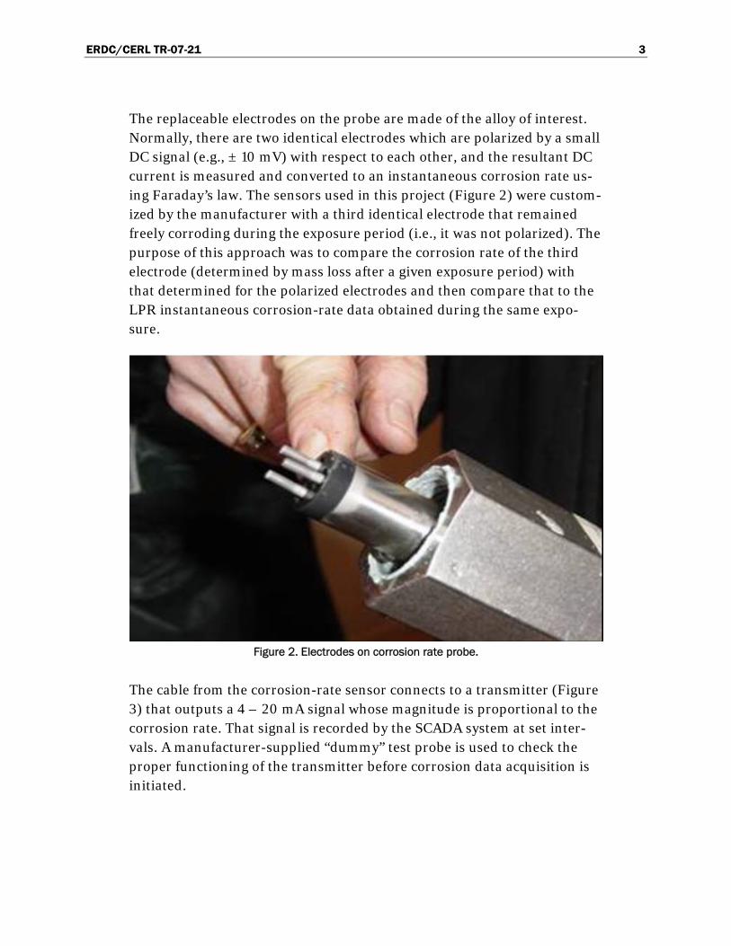
The replaceable electrodes on the probe are made of the alloy of interest. Normally, there are two identical electrodes which are polarized by a small DC signal (e.g., ± 10 mV) with respect to each other, and the resultant DC current is measured and converted to an instantaneous corrosion rate us-ing Faraday’s law. The sensors used in this project (Figure 2) were custom-ized by the manufacturer with a third identical electrode that remained freely corroding during the exposure period (i.e., it was not polarized). The purpose of this approach was to compare the corrosion rate of the third electrode (determined by mass loss after a given exposure period) with that determined for the polarized electrodes and then compare that to the LPR instantaneous corrosion-rate data obtained during the same expo-sure.
Figure 2. Electrodes on corrosion rate probe.
The cable from the corrosion-rate sensor connects to a transmitter (Figure 3) that outputs a 4 – 20 mA signal whose magnitude is proportional to the corrosion rate. That signal is recorded by the SCADA system at set inter-vals. A manufacturer-supplied “dummy” test probe is used to check the proper functioning of the transmitter before corrosion data acquisition is initiated.

ERDC/CERL TR-07-21 4
Figure 3. CORRATER transmitter.
In addition to measuring the instantaneous corrosion rate quantitatively, the CORRATER also measures “imbalance,” which the manufacturer claims is a qualitative indication of pitting tendency. Imbalance is the “gal-vanic” current flow between the two otherwise nominally identical elec-trodes due to an electrical potential difference created by the random pos-sibility that one electrode will undergo (more) pitting compared with the other. The electrodes are not subjected to externally applied polarization during the imbalance measurements. In contrast, during the LPR (instan-taneous corrosion-rate) measurements, the electrodes are polarized by an external DC signal. If the instantaneous corrosion rate is greater than the imbalance reading, general or uniform corrosion is indicated. Conversely, if the imbalance reading is greater than the instantaneous corrosion rate, localized (pitting) corrosion is indicated.
Rohrback’s CORRATER manual, illustrating the transmitter module, specifications, wiring, installation, operation, verification, and the imbal-ance function, is included in Appendix B.
The preweighed CORRATER electrodes for this project were also pur-chased from Rohrback and reportedly fabricated from pipe-grade carbon

ERDC/CERL TR-07-21 5
steel (UNS K03005). The initial weights of the electrodes and mass loss after a certain exposure period are detailed in Chapter 3 under “Results.”
Water chemistry sensors
The commercial water chemistry sensor used in this project is depicted in Figure 4 and is commonly known as the PipeSonde In-Pipe Probe, manu-factured by the Hach Corporation of Loveland, CO. The PipeSonde is based on well established instrumentation methods for measuring water chemistry parameters: pH, oxidation/reduction potential (ORP), conduc-tivity, dissolved oxygen (DO), turbidity, pressure, and temperature. It con-sists of a stainless steel tubular body that contains the sensors at the front end, protected by a metal guard sleeve. The signal conditioner and trans-mitter module is contained in the probe body. (In some models there is also a self-contained data-logger in the body.) The probe is installed into the system through a long, internally-threaded stainless steel sleeve (corp adapter). Removable handles are provided to facilitate insertion and re-moval of the probe.
The measurement parameters, principles, and units for the sensors in the PipeSonde probe are summarized as follows:
1. pH – measured using a small pH-glass electrode to indicate acid or base; units pH scale 0 to 14
2. ORP – potential of a small platinum electrode (band) versus a sil-ver/silver-chloride/saturated potassium-chloride (Ag/AgCl/sat. KCl) ref-erence electrode; units millivolts (mV) converted to the standard hydrogen scale (SHE)
3. conductivity – current to voltage ratio between two electrodes in a conduc-tivity cell of a fixed geometry; units micro-Siemens, µS; or milli-Siemens, mS
4. dissolved oxygen – measured using a new, solid-state, luminescent dis-solved oxygen (LDO) sensor based on optical fluorescence – replaces the older polarographic/galvanic membrane sensor; units milligrams per liter (mg/L), i.e., parts per million (ppm); or % saturation
5. turbidity – measured by amount of light scattering (e.g., due to dissolved and suspended solids) over a defined angular range; units Nephelometric Turbidity Units (NTU)
6. pressure – measured by a pressure transducer; units pounds per square inch (psi)

ERDC/CERL TR-07-21 6
7. temperature – measured by a thermocouple; units degrees Farenheit or degrees Celsius.
The PipeSonde sensors are calibrated using standard solutions and manu-facturer-supplied software. The PipeSonde user’s manual and probe-calibration software manual are included in Appendix C.

ERDC/CERL TR-07-21 7
2 Lessons Learned
The project team learned several valuable lessons that will be useful to DoD installations wishing to implement pipe corrosion and water corro-sivity sensors with a SCADA interface.
Site selection lessons
Manufacturer guidance should be followed carefully when selecting loca-tions for the installation of sensors. Each manufacturer will generally have several site selection criteria that must be met to ensure proper sensor in-stallation and performance. If the sensors are to be interfaced with a SCADA system, there will be additional criteria to consider. Typical crite-ria will include:
1. Space and sensor orientation requirements. The location that is selected must be able to physically accommodate the sensor in its proper orienta-tion, along with any launchers or installers. Adjacent walls, floors, equip-ment, or other pipes may make this challenging, especially in underground vaults where space is limited. Sensors and their accessories should be placed so that they do not create a tripping hazard or other safety hazard to personnel.
2. Required pipe size and flow. The sensors used in this project could only be installed in pipes that were 8 inches or larger in diameter. This may vary for other sensors. “Dead-end” pipes and abandoned pipes should generally be avoided.
3. Environment. Although these sensors are intended for field use, they are not designed to be buried in soil or submerged in water. For best results, sensors that are being installed below ground should be placed in a prop-erly sized and well drained concrete vault with a concrete floor.
4. Location of SCADA Remote Terminal Units (RTUs). If the sensors are to be interfaced with a SCADA system, they generally must be placed within a certain maximum distance from the SCADA RTUs to ensure accurate transmission of signals. The SCADA system contractor or responsible per-son should be contacted to determine what this distance is for the specific system.
5. Availability of electric power. All of these sensors require electric power to operate. Each site should be checked to ensure that electric power at the correct voltage is available nearby.

ERDC/CERL TR-07-21 8
Sensor installation lessons
At the time of this writing, it is generally recommended that the Hach PipeSonde water chemistry sensors (or other sensors of similar complex-ity) be installed by the manufacturer. It is also recommended that the manufacturer be required to supply all of the components for installation, including the sensor, adapter, pipe saddle, access valve, and pipe nipple. The manufacturer also should perform a final quality control check of each complete probe assembly at the factory by fully inserting the probe into its designated corp* adapter and removing it to check for any problems with jamming, binding, or sticking. Although this requirement may add to first costs, it would avoid several major problems and delays that occurred dur-ing this demonstration.
SCADA interface lessons
If the sensors are going to be interfaced with a SCADA or other data acqui-sition system, it is critical to involve the SCADA system experts (contrac-tors and/or installation personnel) as early in the process as possible. Be very clear — explicitly clear — about what is to be done and what the end results (such as data displays) are to look like.
Ask the SCADA experts to review the sensor specifications before work be-gins. Discuss exactly how and where all of the system components are go-ing to be connected. Do not leave anything to chance in this area. Identify any additional interface boards, adapters, enclosures, wires/cables, etc., that are needed. Make sure the SCADA experts understand the signals that the sensors are going to produce, and make sure the SCADA system can process them. If not, determine what kinds of adapters or converters are needed. Have the SCADA expert talk with the sensor manufacturer if nec-essary. Complicated and expensive interface and communication problems can be avoided by addressing these issues before implementation begins.
Make sure that the SCADA programmers understand how to translate the unprocessed sensor data into information that is meaningful to the user of the data. It is very easy to make mistakes in this area. For example, in the current demonstration, the corrosion-rate sensors produce a 4 – 20 mA signal. However, the users at the DPW office are interested in the instan-
* Corp: common term for corporation stop, which is a threaded valve that can be added to a water main without interrupting water service. It allows the connection or disconnection of a service line without shutting off water flow at the main, and is a convenient way to install sensors on a distribution network.

ERDC/CERL TR-07-21 9
taneous corrosion rate, percentage of metal loss, and thickness loss ex-pressed in mils per year. Signal conversion is done through programming, so errors in programming will cause the data to be interpreted and dis-played incorrectly, and the water treatment plant operator will be basing decisions based erroneous information.
Maintenance and calibration
The project team learned that it is critical to keep the sensors cleaned and calibrated after they are installed. The required frequency for this will vary depending upon site-specific conditions such as water chemistry and flow rates. A 6 month interval for cleaning was found to be too long for water conditions at Fort Bragg; during that amount of time the sensors became so badly fouled with deposits and debris that they were no longer produc-ing accurate data.
Follow the manufacturer’s recommendations about sensor calibration fre-quency to help ensure that accurate data are continually provided. Some manufacturers (such as Hach) offer field service programs in which an en-gineer will make periodic site visits to calibrate, clean, and maintain the sensors. Service programs are usually purchased on an annual basis. Such programs are especially recommended for installations that do not have enough personnel to perform the calibrations.

ERDC/CERL TR-07-21 10
3 Technical Investigation
Problem statement
Severe general or localized internal corrosion can significantly shorten the service life of potable water distribution systems. The first line of defense against internal pipe corrosion is a good water treatment program. Raw water chemistry tends to fluctuate over time, and the quality of water tends to degrade after it leaves the treatment plant and flows through the distribution system. These changes in chemistry typically are not evident to treatment plant personnel during routine grab sampling. Furthermore, corrosion problems within the distribution network often remain unde-tected until a leak or failure occurs. Corrosion rate and water quality sen-sors in the distribution system could provide valuable information that would allow the treatment plant operator to fine-tune the chemical treat-ment program. However, the effectiveness of such sensors in a field appli-cation had not previously been verified.
Approach
The contractor developed work, communications, and data collection plans as well as a safety manual. Those documents are included in Appen-dix D.
An initial site visit to Fort Bragg was conducted to select the locations for the installation of the sensors. Discussions between water-plant personnel, DPW, and ERDC-CERL led to the selection of the following four monitor-ing locations:
1. Tank Hill – closest to water-storage tank and SCADA box 2. Water plant – raw water (nearest clearwell V-3510) 3. Water plant – finished water; outside high-pressure pump house 4. Simmons Army Airfield.
These locations were selected to reflect a range of conditions in the water system. They also met the sensor manufacturers’ criteria for site selection. At the water plant, clearwell V-3510 represented raw (untreated) water to serve as a baseline. The nearby high-pressure pump house location repre-sented finished water (i.e., after chlorination and addition of corrosion and
ERDC/CERL TR-07-21 11
scale inhibitors). Thus, those locations provided a direct comparison be-tween raw and finished water in the pipe system. The Simmons Army Air-field represented a distant downstream location that would help to deter-mine conditions within the system such as dissipation of the water treatment chemicals. Finally, the Tank Hill location was selected because it was believed to represent “average” distribution system conditions.
Probe installation
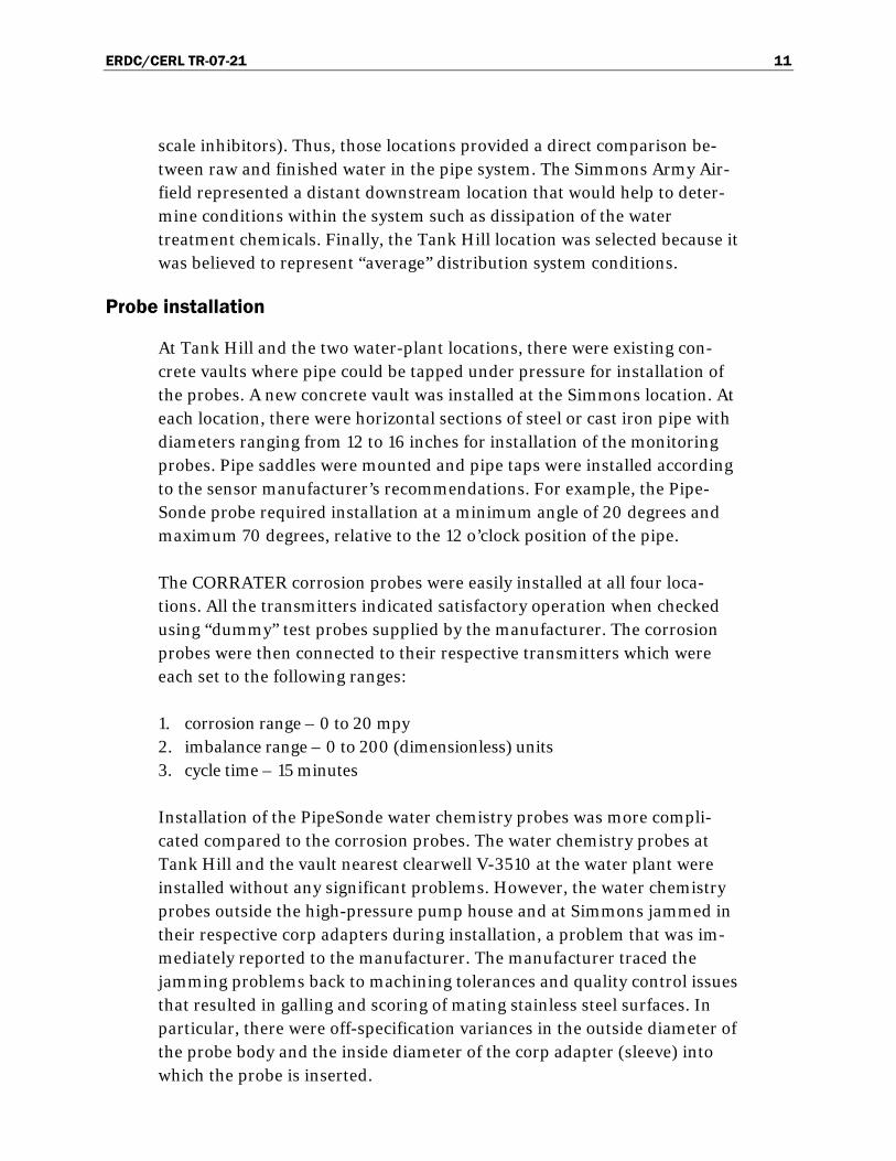
At Tank Hill and the two water-plant locations, there were existing con-crete vaults where pipe could be tapped under pressure for installation of the probes. A new concrete vault was installed at the Simmons location. At each location, there were horizontal sections of steel or cast iron pipe with diameters ranging from 12 to 16 inches for installation of the monitoring probes. Pipe saddles were mounted and pipe taps were installed according to the sensor manufacturer’s recommendations. For example, the Pipe-Sonde probe required installation at a minimum angle of 20 degrees and maximum 70 degrees, relative to the 12 o’clock position of the pipe.
The CORRATER corrosion probes were easily installed at all four loca-tions. All the transmitters indicated satisfactory operation when checked using “dummy” test probes supplied by the manufacturer. The corrosion probes were then connected to their respective transmitters which were each set to the following ranges:
1. corrosion range – 0 to 20 mpy 2. imbalance range – 0 to 200 (dimensionless) units 3. cycle time – 15 minutes
Installation of the PipeSonde water chemistry probes was more compli-cated compared to the corrosion probes. The water chemistry probes at Tank Hill and the vault nearest clearwell V-3510 at the water plant were installed without any significant problems. However, the water chemistry probes outside the high-pressure pump house and at Simmons jammed in their respective corp adapters during installation, a problem that was im-mediately reported to the manufacturer. The manufacturer traced the jamming problems back to machining tolerances and quality control issues that resulted in galling and scoring of mating stainless steel surfaces. In particular, there were off-specification variances in the outside diameter of the probe body and the inside diameter of the corp adapter (sleeve) into which the probe is inserted.

ERDC/CERL TR-07-21 12
After troubleshooting and several iterations, a design change was imple-mented by the manufacturer to increase the bore size of the corp adapter and insert a PVC sleeve between the corp and the probe body. The PVC sleeve serves as a bushing to separate the two mating stainless steel sur-faces and prevent galling and scoring. It is noted that correction of this jamming problem delayed the project by several months before the probes could successfully be installed outside the high-pressure pump house at the water plant and in the Simmons’ vault.
The probes installed at the four monitoring locations are shown in Figure 5 through Figure 9. The corrosion probe was installed upstream of the wa-ter chemistry probe at all locations. The corrosion probe’s freely-corroding (i.e., unpolarized) electrode was always oriented downstream of the polar-ized electrode pair, as illustrated in Figure 10.
Figure 4. Hach PipeSonde probe.

ERDC/CERL TR-07-21 13
Figure 5. Sensors in the raw water line at the water plant.
Figure 6. Sensors in the treated (finished) water line at the water treatment plant.

ERDC/CERL TR-07-21 14
Figure 7. New vault and SCADA box at Simmons Army Airfield
Figure 8. Sensors in Simmons vault before pouring of concrete floor.

ERDC/CERL TR-07-21 15
Figure 9. Corrosion sensor in new vault at Tank Hill.
Figure 10. Orientation of corrosion sensor LPR electrodes.

ERDC/CERL TR-07-21 16
Data acquisition
The existing SCADA subcontractor at Fort Bragg, MSE-TA, was retained under contract to interface the corrosion and water chemistry probes at all four locations and program the system for data acquisition. MSE-TA in-stalled conduits and cables from the probes to existing SCADA boxes at three locations. At Simmons, MSE-TA installed a new SCADA box outside the new vault. The interior of a typical SCADA box at Fort Bragg is shown in Figure 11.
Figure 11. Typical SCADA box at Fort Bragg.

ERDC/CERL TR-07-21 17
The probes at Tank Hill and Simmons were successfully interfaced to their respective SCADA boxes for data acquisition. However, some problems were encountered in interfacing the two water chemistry probes at the wa-ter plant to the existing, single SCADA box located in the pump house. Af-ter considerable troubleshooting, the problem was attributed to RS-485 network communications difficulties when the two probes were connected to a single programmable logic controller (PLC) in the SCADA box. The probe manufacturer’s regional service manager eventually resolved the problem by installing an “Adams module,” which converts the RS-485 to an RS-232 communication protocol.
Probe transmitter calibration and onsite training
After successful installation, the water chemistry probes were calibrated one at a time in the water-plant laboratory using standard solutions of known value for pH, conductivity, turbidity, etc. On-site training during calibration was provided by the probe manufacturer’s regional service manager to designated plant personnel. Calibration was performed using the probe manufacturer’s software program in a laptop computer.
The corrosion probes themselves do not require calibration, according to the manufacturer. The sensor transmitters should be checked for correct operation periodically by using the manufacturer-provided test (dummy) probes. With the transmitter module set to a corrosion range of 20 mpy, imbalance to 20 units, cycle time to 5 minutes, and alloy multiplier to 1.00, the test probe should give a value of 5 mpy (which is equivalent to electrical current of 8.00 ± 0.25 mA for the 4 – 20 mA loop), verifying cor-rect instrument operation. These checks were made in-situ for the subject probes at Fort Bragg one at a time; all four transmitters were found to be functioning properly.
Results
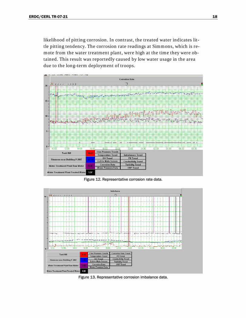
Representative data from the CORRATERs for instantaneous corrosion rate and corrosion imbalance are depicted in Figure 12 and Figure 13. These data were captured from the SCADA terminal in the DPW office. A primer on corrosion and basic data interpretation is presented in Appen-dix E. An appreciable reduction (> 80%) in the general corrosion rate of steel due to water treatment (reported to contain corrosion inhibitors) is indicated immediately (compare raw versus treated water). Also, signifi-cant spikes in the raw water imbalance readings periodically indicate the
ERDC/CERL TR-07-21 18
likelihood of pitting corrosion. In contrast, the treated water indicates lit-tle pitting tendency. The corrosion rate readings at Simmons, which is re-mote from the water treatment plant, were high at the time they were ob-tained. This result was reportedly caused by low water usage in the area due to the long-term deployment of troops.
Figure 12. Representative corrosion rate data.
Figure 13. Representative corrosion imbalance data.

ERDC/CERL TR-07-21 19
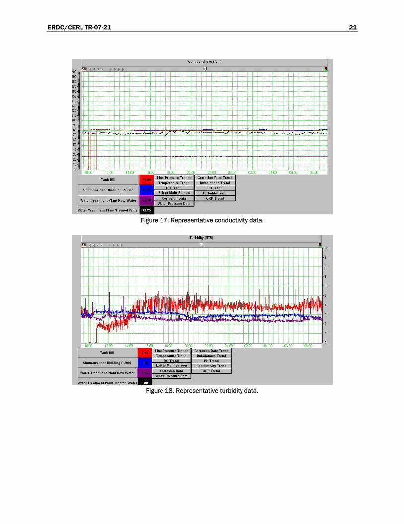
Representative water chemistry data from the PipeSondes are illustrated graphically in Figure 14 through Figure 18. These data were captured from the SCADA terminal in the DPW office. (The spikes in the Tank Hill data between 10 and 11 A. M. occurred because the sensors were briefly re-moved and disconnected during the training of DPW personnel.) A primer on water chemistry parameters and basic data interpretation is presented in Appendix E. The data in Figure 14 indicate that the pH of treated water is nearly 3 units higher (i.e., less acidic) than that of untreated water. Figure 15 shows that the dissolved oxygen content was almost the same at all locations. The pH trend correlates well with the preliminary corrosion data discussed above. The higher oxidation/reduction potential (ORP) values for treated water compared with untreated water (Figure 16) could be attributed to the chlorination that is used for disinfection. Figure 17 shows that the conductivity of the raw water is much lower than that of the treated water.
Figure 14. Representative pH data.

ERDC/CERL TR-07-21 20
Figure 15. Representative dissolved oxygen (DO) data.
Figure 16. Representative ORP data.
ERDC/CERL TR-07-21 21
Figure 17. Representative conductivity data.
Figure 18. Representative turbidity data.

ERDC/CERL TR-07-21 22
Figure 19. Representative pressure data.
The turbidity of treated water (Figure 18) is lower, as is normally expected, compared with that of untreated water. Turbidity appears to increase as water passes through the system. This may indicate the presence of dis-solved corrosion products at the Tank Hill and Simmons locations, which is consistent with the higher corrosion rates noted previously. Figure 19 shows the pressure variations.
The data from the SCADA system are displayed on a monitor in the DPW office, either graphically as shown in the preceding figures, or as a table (Figure 20).
Figure 20. Tabular display of data on SCADA terminal in DPW office.

ERDC/CERL TR-07-21 23
PipeSonde and grab sample data
Comparison of PipeSonde data with the analysis results for water samples obtained at the sensor locations is ongoing and will continue through the end of Fiscal Year 2007 (FY07). Water sample dissolved oxygen, dissolved carbon dioxide, and pH are measured in the field immediately after the samples are obtained. The samples are then sent to the Illinois State Water Survey, Champaign, IL, for comprehensive laboratory analysis.
An earlier attempt to validate sensor accuracy was made approximately 6 months after the sensors were installed. The results of the laboratory analysis were significantly different than the sensor readings. This finding prompted the team to remove and inspect the sensors to determine the source of the discrepancy. The sensor tips were found to be severely scaled and fouled, and the manufacturer indicated that they would be incapable 0f making accurate readings in that condition. The manufacturer recom-mended more frequent (quarterly) cleaning and calibration. Such a pro-gram has been implemented.
A malfunction in the SCADA system was also discovered during the earlier attempt to validate sensor accuracy. The malfunction was causing the data from the sensors to be reported inaccurately. The problem was not discov-ered immediately because the values being reported by the SCADA system were still within reasonable ranges. The problem was repaired and the ac-curacy of data transmission was validated.
Preliminary field results obtained after correction of the issues described above are shown in Table 1 through Table 4. Direct sensor interrogation readings were measured directly off of the PipeSonde using a Hach Sur-veyor 4a handheld data logger. SCADA reading was obtained from the SCADA system terminal in the DPW office within 5 minutes of the direct interrogation. (It should be noted that it is not possible to obtain the SCADA and direct sensor readings at exactly the same time because the sensor must be temporarily disconnected from the SCADA during the di-rect interrogation.) Grab sample field analysis was conducted using a portable pH meter and a portable dissolved oxygen test kit.

ERDC/CERL TR-07-21 24
Table 1. Field data obtained from PipeSonde at Tank Hill.
Parameter Direct sensor interrogation
SCADA Reading
Grab sample field analysis
pH (Time: 1050) 8.00 8.07
pH (Time: 1235) 7.56 7.60
ORP (mV) 600.00 600.07 N/A
Temperature (F) 74.80 74.60 79.7
DO (mg/l) 7.87 7.92 4.8
Conductivity (µS) 80.00 80.70 Lab
Pressure (psi) 34.00 33.82 N/A
Turbidity (NTU) 0.70 1.96 Lab
Table 2. Field data obtained from PipeSonde at Simmons Army Airfield.
Parameter Direct sensor interrogation
SCADA Reading
Grab sample analysis
pH 7.6 7.63 7.18
ORP (mV) 649 649.07 N/A
Temperature (F) 75.4 75.06 Not obtained
DO (mg/l) 6.6 6.57 5.2
Conductivity (µS) 86.3 81.53 Lab
Pressure (psi) 66.15 66.89 N/A
Turbidity (NTU) 2.6 3.35 Lab
Table 3. Field data obtained from PipeSonde on raw water line at WTP.
Parameter Direct sensor interrogation
SCADA Reading
Grab sample analysis
pH 5.88 5.87 5.66
ORP (mV) 482 479.02 N/A
Temperature (F) 74.3 74.25 75.9
DO (mg/l) 7.34 7.36 6.4
Conductivity (µS) 28 27.07 Lab
Pressure (psi) 11.46 11.39 N/A
Turbidity (NTU) 2.2 2.39 Lab

ERDC/CERL TR-07-21 25
Table 4. Field data obtained from PipeSonde on treated water line at WTP.
Parameter Direct sensor interrogation
SCADA Reading
Grab sample analysis
pH 7.17 7.16 7.38
ORP (mV) 671 664.56 N/A
Temperature (F) 74.7 74.67 76.2
DO (mg/l) 7.17 7.15 5.28
Conductivity (µS) 75.7 71.29 Lab
Pressure (psi) 113.4 111.33 N/A
Turbidity (NTU) 0 0 Lab
Comparison of the grab sample pH, dissolved oxygen, and temperature testing results with the sensor interrogation results indicates acceptable sensor accuracy. It should be noted that the dissolved oxygen concentra-tions in the grab samples are expected to be lower than the sensor readings because dissolved oxygen begins dissipating the instant the sample is re-moved from the pipe.
Comparison of the direct interrogation data and the SCADA reading indi-cates that the SCADA system continues to report data accurately.
Complete field and laboratory results will be presented in the final report on this demonstration project.
Mass loss measurements
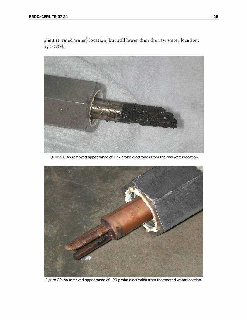
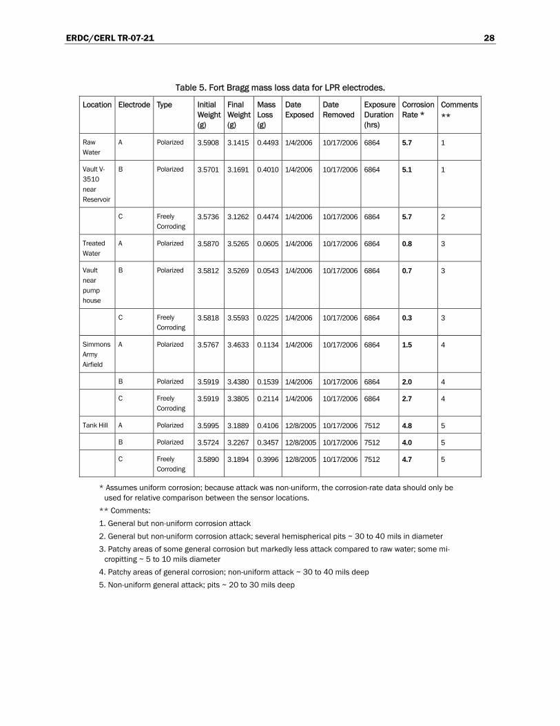
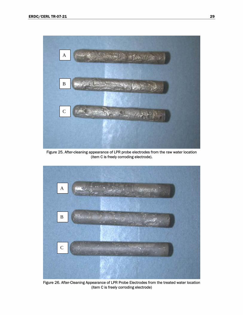
The electrodes from the corrosion sensors were recovered for examination and mass loss determination. The appearance of the as-removed elec-trodes is shown in Figure 21 through Figure 24. The electrodes were chemically cleaned in Clarke’s solution (inhibited hydrochloric acid) ac-cording to ASTM Standard G-1 to remove the corrosion products. The af-ter-cleaning appearance of the electrodes is shown in Figure 25 through Figure 28. The mass-loss corrosion data are summarized in Table 5. It is apparent that the highest corrosion rates were exhibited for the raw water and Tank Hill locations. The concentration of corrosion products fouling the electrode surfaces was also highest for these locations. In contrast, the mass loss for the treated water location was markedly lower, indicating the highly effective nature of the water treatment. The degree of corrosion products on the LPR electrodes is also minimal compared with the raw water location. The mass loss at Simmons was higher than at the water
ERDC/CERL TR-07-21 26
plant (treated water) location, but still lower than the raw water location, by > 50%.
Figure 21. As-removed appearance of LPR probe electrodes from the raw water location.
Figure 22. As-removed appearance of LPR probe electrodes from the treated water location.

ERDC/CERL TR-07-21 27
Figure 23. As-removed appearance of LPR probe electrodes from Simmons Army Airfield.
Figure 24. As-removed appearance of LPR probe electrodes from Tank Hill.
ERDC/CERL TR-07-21 28
Table 5. Fort Bragg mass loss data for LPR electrodes.
Location Electrode Type Initial Weight (g)
Final Weight (g)
Mass Loss (g)
Date Exposed
Date Removed
Exposure Duration (hrs)
Corrosion Rate *
Comments **
Raw Water
A Polarized 3.5908 3.1415 0.4493 1/4/2006 10/17/2006 6864 5.7 1
Vault V-3510 near Reservoir
B Polarized 3.5701 3.1691 0.4010 1/4/2006 10/17/2006 6864 5.1 1
C Freely Corroding
3.5736 3.1262 0.4474 1/4/2006 10/17/2006 6864 5.7 2
Treated Water
A Polarized 3.5870 3.5265 0.0605 1/4/2006 10/17/2006 6864 0.8 3
Vault near pump house
B Polarized 3.5812 3.5269 0.0543 1/4/2006 10/17/2006 6864 0.7 3
C Freely Corroding
3.5818 3.5593 0.0225 1/4/2006 10/17/2006 6864 0.3 3
Simmons Army Airfield
A Polarized 3.5767 3.4633 0.1134 1/4/2006 10/17/2006 6864 1.5 4
B Polarized 3.5919 3.4380 0.1539 1/4/2006 10/17/2006 6864 2.0 4
C Freely Corroding
3.5919 3.3805 0.2114 1/4/2006 10/17/2006 6864 2.7 4
Tank Hill A Polarized 3.5995 3.1889 0.4106 12/8/2005 10/17/2006 7512 4.8 5
B Polarized 3.5724 3.2267 0.3457 12/8/2005 10/17/2006 7512 4.0 5
C Freely Corroding
3.5890 3.1894 0.3996 12/8/2005 10/17/2006 7512 4.7 5
* Assumes uniform corrosion; because attack was non-uniform, the corrosion-rate data should only be used for relative comparison between the sensor locations.
** Comments:
1. General but non-uniform corrosion attack
2. General but non-uniform corrosion attack; several hemispherical pits ~ 30 to 40 mils in diameter
3. Patchy areas of some general corrosion but markedly less attack compared to raw water; some mi-cropitting ~ 5 to 10 mils diameter
4. Patchy areas of general corrosion; non-uniform attack ~ 30 to 40 mils deep
5. Non-uniform general attack; pits ~ 20 to 30 mils deep
ERDC/CERL TR-07-21 29
Figure 25. After-cleaning appearance of LPR probe electrodes from the raw water location
(item C is freely corroding electrode).
Figure 26. After-Cleaning Appearance of LPR Probe Electrodes from the treated water location
(item C is freely corroding electrode)
A
B
C
A
B
C

ERDC/CERL TR-07-21 30
Figure 27. After-cleaning appearance of LPR probe electrodes from the Simmons Army Airfield
(item C is freely corroding electrode).
Figure 28. After-cleaning appearance of LPR probe electrodes from Tank Hill
(item C-is freely corroding electrode).
A
B
C
A
B
C

ERDC/CERL TR-07-21 31
Mass loss from the freely corroding electrode at each location was similar to that from the polarized electrodes. This result demonstrates that a two-electrode probe would be adequate for LPR measurements as well as mass loss. Corrosion attack was general, but not uniform at all locations. Vary-ing degrees of pitting attack was observed on all the LPR electrodes.

ERDC/CERL TR-07-21 32
4 Metrics
The baseline measure of corrosion rate in the potable water system at Fort Bragg was obtained by installing a CORRATER corrosion-rate sensor on the pipe that conveys raw (untreated) water into the water treatment plant. This sensor measures the rate at which a steel pipe exposed to un-treated Fort Bragg water would be expected to corrode. This rate was then compared with the corrosion rate measured by CORRATERs located in pipes that convey treated water at various locations in the distribution sys-tem. The comparison provides a quantitative measure of the effectiveness of the water treatment program.
A pipe coupon test rack is being used to measure the corrosion rate of various metals exposed to the treated water at the water treatment plant. The metric is ASTM D2688-05, Standard Test Methods for Corrosivity of Water in the Absence of Heat Transfer (Weight Loss Methods). The re-sults of this testing will be presented in the final report.
Additionally, the instantaneous corrosion-rate data provided by each CORRATER will be integrated over time to measure total electrode mass loss. Those data will be compared with the corrosion rate obtained by con-ducting mass loss measurements on a non-polarized, freely corroding elec-trode installed in the system. The mass loss metric is ASTM G1-03, Stan-dard Practice for Preparing, Cleaning, and Evaluating Corrosion Test Specimens. The results will be presented in the final report.
Comparison of PipeSonde data with the analysis results of water samples obtained at the sensor locations is ongoing and will be presented in the fi-nal report.
ERDC/CERL TR-07-21 33
5 Economic Summary
Costs and assumptions
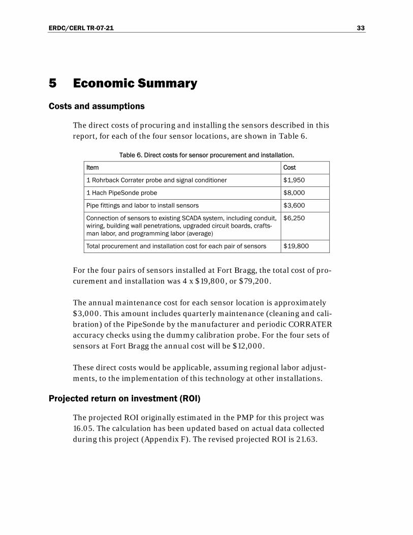
The direct costs of procuring and installing the sensors described in this report, for each of the four sensor locations, are shown in Table 6.
Table 6. Direct costs for sensor procurement and installation.
Item Cost
1 Rohrback Corrater probe and signal conditioner $1,950
1 Hach PipeSonde probe $8,000
Pipe fittings and labor to install sensors $3,600
Connection of sensors to existing SCADA system, including conduit, wiring, building wall penetrations, upgraded circuit boards, crafts-man labor, and programming labor (average)
$6,250
Total procurement and installation cost for each pair of sensors $19,800
For the four pairs of sensors installed at Fort Bragg, the total cost of pro-curement and installation was 4 x $19,800, or $79,200.
The annual maintenance cost for each sensor location is approximately $3,000. This amount includes quarterly maintenance (cleaning and cali-bration) of the PipeSonde by the manufacturer and periodic CORRATER accuracy checks using the dummy calibration probe. For the four sets of sensors at Fort Bragg the annual cost will be $12,000.
These direct costs would be applicable, assuming regional labor adjust-ments, to the implementation of this technology at other installations.
Projected return on investment (ROI)
The projected ROI originally estimated in the PMP for this project was 16.05. The calculation has been updated based on actual data collected during this project (Appendix F). The revised projected ROI is 21.63.

ERDC/CERL TR-07-21 34
6 Recommendation
It is recommended that the managers of U.S. military installations fully consider utilizing corrosion rate and water quality/corrosivity sensors to monitor select points within the water distribution system. The data ob-tained can be used to tailor water treatment to local conditions and inhibit the corrosion of distribution system components.
The lessons learned documented in Chapter 2 of this report should be fol-lowed carefully to help ensure an accurate and trouble-free implementa-tion.
ERDC/CERL TR-07-21 35
7 Implementation
This technology may be implemented in DoD policy through inclusion in the applicable Unified Facilities Criteria (UFC) and Technical Manuals (TM). The primary implementation documents would be:
1. UFC 3-230-08A, Design: Water Supply: Water Treatment 2. Army TM 5-813-3, Water Supply, Water Treatment 3. Army TM 5-813-5, Water Supply, Water Distribution 4. UFC 3-401-01FA, Design: Utility Monitoring and Control Systems 5. UFGS-33-11-00, Water Distribution 6. UFGS-02-51-3, Precipitation/Coagulation/Flocculation Water Treat-
ment.

ERDC/CERL TR-07-21 36
8 Conclusion
The corrosion and water chemistry sensors installed at four locations in the potable water system at Fort Bragg are providing real-time data.
The instantaneous corrosion-rate data generated by the Rohrback Cosasco CORRATER probe, when integrated over time, will be compared with mass loss as measured over the same time period using ASTM G1-03.
With proper calibration and maintenance of the probes, the sensor data can reveal important trends in water chemistry and corrosion conditions. Data collected over an extended period will reveal historical trends that can serve as baseline data for ongoing correlation and interpretation to op-timize potable water treatment.

ERDC/CERL TR-07-21 A1
Appendix A: Project Management Plan for CPC Project AR-F-317

TRISERVICE PROGRAM ARMY FACILITIES
CORROSION PREVENTION AND CONTROL PROJECT PLAN
Pipe Corrosion Sensors at Fort Bragg
14 July 2004
Submitted By:
Vincent F. Hock
U. S. Army Engineer Research & Development Center (ERDC) Construction Engineering Research Laboratory (CERL)
Comm: 217-373-6753
______________________________ (Project Number to be assigned by OSD when approved)

CORROSION PREVENTION AND CONTROL PROJECT PLAN Pipe Corrosion Sensors at Fort Bragg
2
1. STATEMENT OF NEED
PROBLEM STATEMENT: Army and DoD facilities managers have identified water distribution systems as a critical part of the infrastructure needed to support fire suppression, troop deployment to arid regions, and soldier welfare. Many DoD water systems are over 50 years old and are plagued with widespread and costly corrosion-induced leaks and failures. For example, annual operation and maintenance costs for Fort Bragg’s water system have been estimated at $2.6 million. Badly-needed water system capital improvement projects (such as replacement of failed piping) costing approximately $1.5 million per year have also been identified. In addition to the high maintenance and capital replacement costs, a corroded and leaking water distribution system often loses as much as 20 to 25% of the water it conveys. At a large installation this can amount to over 1 million gallons of wasted water per day. Severe internal corrosion of unlined steel, cast iron, or ductile iron pipes usually results in poor water quality for occupants—water containing dissolved corrosion products (“rust”) is frequently discolored and may have an unpleasant taste and/or odor. In some cases the water may exceed the maximum contaminant level for iron of 0.3 mg/l as specified in the Environmental Protection Agency’s National Secondary Drinking Water Regulations. The worst case is an unexpected catastrophic failure that occurs when the piping system is under stress due to high usage or environmental conditions, such as during firefighting, deployment, or severely cold weather. Failure of a critical water main during a firefighting situation can result in loss of lives and property. Failure of a critical water main during deployment can cause unacceptable delays that compromise the mission. There are several industry-accepted alternatives for dealing with corrosion in water systems. The service life of piping that is new to moderately deteriorated can be dramatically extended by installing an internal lining, or by applying system-wide and/or localized water treatment. The only alternative for a badly deteriorated water main may be replacement. However, before we can take corrective action, we must (1) detect that there is a problem, (2) determine where the problem is, and (3) characterize the nature and severity of the problem. Because the piping system is buried in the ground, it is very difficult to detect, locate, and characterize corrosion problems until widespread failures have occurred. Even the routine water quality testing that is conducted at the treatment plant will not detect remote and/or localized corrosion or water corrosivity problems. Pipes can be inspected manually through the use of internal video cameras or leak detection devices, but these techniques are expensive (especially for systems such as Fort Bragg’s that are several hundred miles long) and only give a one-time “snapshot” of the system’s condition.
CORROSION PREVENTION AND CONTROL PROJECT PLAN Pipe Corrosion Sensors at Fort Bragg
3
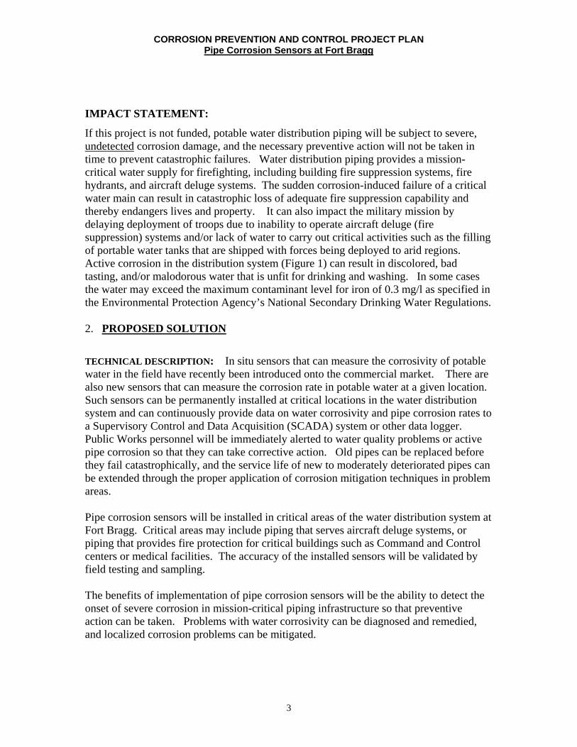
IMPACT STATEMENT:
If this project is not funded, potable water distribution piping will be subject to severe, undetected corrosion damage, and the necessary preventive action will not be taken in time to prevent catastrophic failures. Water distribution piping provides a mission-critical water supply for firefighting, including building fire suppression systems, fire hydrants, and aircraft deluge systems. The sudden corrosion-induced failure of a critical water main can result in catastrophic loss of adequate fire suppression capability and thereby endangers lives and property. It can also impact the military mission by delaying deployment of troops due to inability to operate aircraft deluge (fire suppression) systems and/or lack of water to carry out critical activities such as the filling of portable water tanks that are shipped with forces being deployed to arid regions. Active corrosion in the distribution system (Figure 1) can result in discolored, bad tasting, and/or malodorous water that is unfit for drinking and washing. In some cases the water may exceed the maximum contaminant level for iron of 0.3 mg/l as specified in the Environmental Protection Agency’s National Secondary Drinking Water Regulations.
2. PROPOSED SOLUTION
TECHNICAL DESCRIPTION: In situ sensors that can measure the corrosivity of potable water in the field have recently been introduced onto the commercial market. There are also new sensors that can measure the corrosion rate in potable water at a given location. Such sensors can be permanently installed at critical locations in the water distribution system and can continuously provide data on water corrosivity and pipe corrosion rates to a Supervisory Control and Data Acquisition (SCADA) system or other data logger. Public Works personnel will be immediately alerted to water quality problems or active pipe corrosion so that they can take corrective action. Old pipes can be replaced before they fail catastrophically, and the service life of new to moderately deteriorated pipes can be extended through the proper application of corrosion mitigation techniques in problem areas. Pipe corrosion sensors will be installed in critical areas of the water distribution system at Fort Bragg. Critical areas may include piping that serves aircraft deluge systems, or piping that provides fire protection for critical buildings such as Command and Control centers or medical facilities. The accuracy of the installed sensors will be validated by field testing and sampling. The benefits of implementation of pipe corrosion sensors will be the ability to detect the onset of severe corrosion in mission-critical piping infrastructure so that preventive action can be taken. Problems with water corrosivity can be diagnosed and remedied, and localized corrosion problems can be mitigated.
CORROSION PREVENTION AND CONTROL PROJECT PLAN Pipe Corrosion Sensors at Fort Bragg
4
Implementation of this technology at Fort Bragg is projected to have an ROI of 16.05, and a total savings of $4,011,604. Technology Maturity:
Industry has introduced several new water quality and corrosivity sensors onto the market within the last 2 years. Dramatic improvements in sensor technology for the water industry have been largely driven by the security concerns following 9/11. Water utilities have demanded the capability for better monitoring of water quality, and industry has delivered. One type of in situ sensor that will be installed at Fort Bragg is a water quality and corrosivity sensor (Figure 2) that can measure pH, conductivity, turbidity, dissolved oxygen, oxidation-reduction potiential (ORP), pressure, and temperature. These measurements allow the water’s corrosivity to be assessed so that additional water treatment can be added if needed. Many water quality sensors can only be used in the laboratory, however, this sensor is especially designed for long-term field use and is water and debris-tight. Sensor readings can be fed directly to the existing SCADA system. The other type of in situ sensor that will be installed measures linear polarization resistance, allows the calculation of the actual corrosion rate. Changes in the corrosion rate can be detected within minutes so that problems can be pinpointed and mitigated. The sensor also allows the effectiveness of corrosion mitigation programs to be closely monitored.
In addition, recent advances in engineering analysis software have enabled “live” sensor data to be automatically fed directly into dynamic hydraulic and water quality models. The models provide the water system operator with a complete, near real-time picture of system status based on the data from a small number of sensing locations. Such a model can alert the operator to problems and emergencies in the water system, in addition to improving the efficiency its operation.

CORROSION PREVENTION AND CONTROL PROJECT PLAN Pipe Corrosion Sensors at Fort Bragg
5
Figure 1. a. Water is vital to Army readiness; b. Severely corroded water distribution pipe.
Figure 2. a. Water quality/corrosivity sensor b. Fort Bragg water distribution network

CORROSION PREVENTION AND CONTROL PROJECT PLAN Pipe Corrosion Sensors at Fort Bragg
6
RISK ANALYSIS: This is a low risk project, as the sensors are available commercially, and have been successfully field tested in similar applications. Also, the sites for implementation of this project at Fort Bragg and plans for implementation of this project have been coordinated with Mr. Ted Kientz and Mr. Jason Lyons, (Civil Infrastructure Program Managers). The project will not be parsed into phases. EXPECTED DELIVERABLES AND RESULTS/OUTCOMES: The industry has recently developed cost effective water quality and pipe corrosion sensors that are able to continuously and automatically monitor water distribution systems for evidence of corrosion and improper water quality. The corrosion and water quality monitoring needs of critical/high priority water mains at Fort Bragg will be assessed. Specifications for corrosion and water quality monitoring systems will be developed, and the systems will be constructed and installed. The efficacy of the sensors systems will be determined. It is expected that they will prevent corrosion on the interior tank surfaces and that it will not be damaged by icing conditions. Immediate attention to improper water quality and accelerated corrosion problems can extend the life of a piping system to its design life of 50 to 75 years. PROGRAM MANAGEMENT: The Project Manager will be: Mr. Vincent Hock. The Associate Project Manager will be: Ms. Vicki Van Blaricum. Mr. Martin Savoie is Chief, ERDC/CERL Materials & Structures Branch. The stakeholders are: the Installation DPW POC, Ted Kientz and Jason Lyons (Civil Infrastructure Program Managers, Fort Bragg), Mr. Steve Jackson (IMA-SERO), Mr. Paul Volkman (HQ-IMA), Mr. David Purcell, (HQ-ACSIM), as well as Triservices WIPT representatives, Ms. Nancy Coleal (AFCESA/CESM), and Mr. Tom Tehada (NFESC). The customer is: Mr. Ted Kientz, Civil Infrastructure Program Manager, Fort Bragg. The technology has been requested by Fort Bragg to help improve corrosion control of their critical systems. HQ IMA has provided matching funding in the amount of $100K for this project. (See attached Memorandum from ACSIM Director for Facilities and Housing in Appendix 2). Coordination with the Army Corrosion Program Office will be through Mr. Hilton Mills (AMC). This is a TriService Project. Funds have been requested for Air Force and Navy representatives to participate in the evaluation of technology implementation. The approach for project performance will include use of Type I –In house, organic capabilities, and Type II Existing Contact. A Type II Existing Contractual Agreement is expected to be utilized for this project two months after receipt of funds. 3. COST/BENEFITS ANALYSIS

CORROSION PREVENTION AND CONTROL PROJECT PLAN Pipe Corrosion Sensors at Fort Bragg
7
a. Funding ($K):
Funding Source OSD HQIMA Matching Labor 40 -- Materials 80 100 Travel 10 -- Report 10 -- Air Force/Navy Participation 10 - TOTAL ($K) 150 100
Development Project Budget
The $200K budget is realistic and adequate for the project scope. This budget has been developed based on a detailed needs assessment for the water distribution system in cooperation with the Fort Bragg DPW Office, including Mr. Ted Kientz and Mr. Jason Lyons, Civil Infrastructure Program Managers. HQ IMA plans to provide $100K in matching funds for FY05. ERDC-CERL has conducted a market survey to validate the costs for this project, which have also been extrapolated from ERDC-CERL’s extensive previous experience in the area of water quality analysis and instrumentation.
This project has a high potential ROI>10 (16.05) as well as a significant cost savings of $4,011,604 as shown below. b. Return-On-Investment Computation
1) Projected Useful Life Savings (ULS) is equal to the “Net Present Value (NPV) of Benefits and Savings” calculated from the Spreadsheet shown in Appendix 1 that is based on Appendix B of OMB Circular A94.
ULS= $4,011K (from OMB Spreadsheet in Appendix 1. Assumptions for this calculation are also given in Appendix 1).
2) Project Cost (PC) is shown as “Investment Required” in OMB Spreadsheet in
Appendix 1; PC= $250,000
ULS $4,011K Potential ROI = ------------ = ------------- = 16.05 PC $ 250K
The calculated ROI for this project, which is based on current best practices, projected maintenance and rehab cost, has the potential to increase over the multiple year implementation due to reduction in down time, which will result in increased indirect savings.

CORROSION PREVENTION AND CONTROL PROJECT PLAN Pipe Corrosion Sensors at Fort Bragg
8
c. Mission Criticality: The operational benefits of implementation of this technology for these mission critical systems are: (1) enhanced safety and reliability for water systems due to reduced probability of failure, (2) increased reliability of fire suppression systems including aircraft deluge systems, (3) life extension for mission-critical infrastructure and reduced maintenance and repair.
4. SCHEDULE
MILESTONE CHART
EVENT
TIME (months after
receipt of funds) Award Contract 2 Determine locations for sensors at Fort Bragg 4 Design monitoring system 6 Install sensors and monitoring system 8 Complete Documentation (includes Final Report, Procurement Specification, Ad Fliers 16 Complete potential ROI validation 18
a. Note: If project is approved, bi-monthly status reports will be submitted (i.e.
starting the first week of the second month after contract award and every two months thereafter until final report is completed). These reports will be submitted to the DoD CPC Policy & Oversight office. These reports will include project number, progress summary (and/or any issues), performance goals and metrics and upcoming events.
b. Examples of performance goals and metrics: include achieving specific
milestones, showing positive trend toward achieving the forecasted ROI, reaching specific performance quality levels, meeting test and evaluation parameters, or successfully demonstrating a new system prototype.
Development Project Schedule This project to implement pipe corrosion sensors will be completed, including final report, within 18 months. The goals of the project are: detection of severe corrosion problems and corrosive water in the water distribution system so that the reliability of mission-critical water infrastructure is increased and its service life is extended. Detailed milestones are given in the schedule section. Implementation of the sensors will be provided by Contractors. ERDC-CERL will provide overall management, contract monitoring and provide bi-monthly reports. Existing contract mechanisms, such as IDIQ and BAA will be used. ERDC-CERL will be able to award the contracts within 60 days of receipt of funds. The schedule has been coordinated with the Fort Bragg DPW. Potential contractors have been identified. 5. IMPLEMENTATION

CORROSION PREVENTION AND CONTROL PROJECT PLAN Pipe Corrosion Sensors at Fort Bragg
9
a. Transition approach: Where applicable, Unified Facilities Guide Specifications (UFGS), Engineering Instructions (EI), Technical Instructions (TI), and Technical Manuals (TM), including updates, along with a final report describing the details of the project, will be developed and posted to the OSD Corrosion Exchange website under “Spec & Standards” and “Facilities SIG.” In addition, the guidance will be ERDC-CERL Corrosion Prevention and Control Program (CPCP) website. Coordination with potential users will be an essential part of the transition of the technology.
It is the intent of the Project Management Plan (PMP) to implement this corrosion prevention and control technology at multiple regions and installations over the next 4 years, according to the schedule shown below. Where applicable, the UFGS, EIs, TIs, and TMs, including updates to existing guidance documents, developed for Army-wide implementation during the FY05 project, will be utilized to facilitate the planned implementation over the next 4 years.
FY OSD Funds HQ-IMA Matching Planned Regions Planned Installations 06 250 250 NERO Fort Drum 07 250 250 NWRO Fort Lewis 08 500 500 SWRO Fort Carson; Fort Hood 09 350 350 PARO Fort Shafter
b. Potential ROI validation: Potential ROI will be validated by comparison of operational and maintenance requirements of water systems with corrosion sensors, versus existing systems without corrosion sensors. The calculated ROI for this project, which is based on current best practices, projected maintenance and rehab cost, has the potential to increase over the multiple year implementation due to reduction in water losses, which will result in increased indirect savings. The ROI will be validated by impartial water distribution system experts at the American Water Works Association Research Foundation (AWWARF) such as Mr. Frank Blaha.
c. Final Report: A final report will be written 60 days after the project is completed. The report will reflect the project plan format as implemented and will include lessons learned.
Projected Benefits: These sensors are projected to provide the benefits of extending the life of aging and mission-critical water distribution system piping, including fire suppression piping. They will do this by alerting DPW personnel to the onset of severe corrosion in these systems so that preventive action can be taken immediately.
Operational Readiness All of the system components are commercially available and ready for implementation as solutions to the corrosion problems of the water distribution system at Fort Bragg.

CORROSION PREVENTION AND CONTROL PROJECT PLAN Pipe Corrosion Sensors at Fort Bragg
10
Based on previous experience, this project will enhance the performance, reliability and safety of the water distribution system at Fort Bragg. This technology will support the military mission by helping ensure that (1) aircraft deluge systems and other fire suppression systems are functioning properly and (2) safe, clean drinking water is readily available to fill portable tanks for soldiers who are deploying to arid regions. Management Support This project enjoys the support of the Fort Bragg DPW Office, specifically, Mr. Ted Kientz and Mr. Jason Lyons. Signatures have been obtained from representatives of the Fort Bragg DPW, IMA-SERO Region, HQ-IMA, HQ-ACSIM supporting this project, as shown on the coordination sheet. Moreover, the Army (HQ-IMA) has planned to provide matching funds ($100K) for FY05. See attached Memorandum from ACSIM Director for Facilities and Housing in Appendix 2.

11
TRI SERVICE PROGRAM ARMY FACILITIES
CORROSION PREVENTION AND CONTROL PROJECT PLAN
Pipe Corrosion Sensors at Fort Bragg
6. COORDINATION SHEET ORGANIZATION SIGNATURE DATE Project Manager See attached ______
ERDC/CERL Branch Chief See attached__ ______
Installation DPW POC See attached__ ______
Installation Environmental POC See attached__ ______
IMA Region See attached__ ______
HQ IMA See attached__ ______
HQ ACSIM See attached__ ______
HQ AMC Hilton Mills approved; signature is
being sent under separate cover.
Tri Service Facilities WIPT Chair See attached__ ______
This is a TriService Project. Funds have been requested for Air Force and Navy representatives to
participate in the evaluation of technology implementation.

TRI SERVICE PROGRAM ARMY FACILITIES
CORROSION PREVENTION AND CONTROL PROJECT PLAN
Pipe Corrosion Sensors at Fort Bragg
6. COORDINATION SHEET
ORGANIZATION
Project Manager
ERDC/CERL Branch Chief
Installation DPW POC
Installation Environmental POC
IMA Region
HQIMA
HQACSIM
HQAMC
Tri Service Facilities WIPT Chair
See attached_
See attached_
See attached_
See attached
See attached
See attached_
This is a TriService Project. Funds have been requested for Air Force and Navy representatives to
participate in the evaluation of technology implementation.

TRI SERVICE PROGRAM ARMY FACILITIES
CORROSION PREVENTION AND CONTROL PROJECT PLAN
Pipe Corrosion Sensors at Fort Bragg
6. COORDINATION SHEET
ORGANIZATION
Project Manager
ERDC/CERL Branch Chief
Installation DPW POC
Installation Environmental POC
IMA Region
HQIMA
HQACSIM
HQAMC
Tri Service Facilities WIPT Chair
SIGNATlJRE DATE
This is a TriService Project. Funds have been requested for Air Force and Navy
representatives to participate in the evaluation of technology implementation.

TRI SERVICE PROGRAM ARMY FACILITIES
CORROSION PREVENTION AND CONTROL PROJECT PLAN
Pipe Corrosion Sensors at Fort Bragg
6. COORDINATION SHEET
ORGANIZATION
Project Manager
ERDCICERL Branch Chief
Installation DPW POC
Installation Environmental POC
IMA Region (SG: ) HQIMA
HQACSIM
HQAMC
Tri Service Facilities WIPT Chair
SIGNATURE DATE
This is a TriService Project. Funds have been requested for Air Force and Navy
representatives to participate in the evaluation of technology implementation.
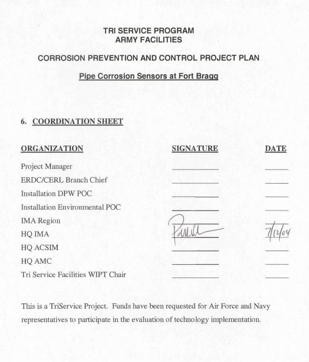
TRI SERVICE PROGRAM ARMY FACILITIES
CORROSION PREVENTION AND CONTROL PROJECT PLAN
Pipe Corrosion Sensors at Fort Bragg
6. COORDINATION SHEET
ORGANIZATION SIGNATURE
Project Manager
ERDC/CERL Branch Chief
Installation DPW POC
Installation EnviroIllllental POC
IMA Region
~.~ HQIMA
HQACSIM
HQAMC
Tri Service Facilities WIPT Chair
DATE
7~ft(
This is a TriService Project. Funds have been requested for Air Force and Navy
representatives to participate in the evaluation of technology implementation.

TRI SERVICE PROGRAM ARMY FACILITIES
CORROSION PREVENTION AND CONTROL PROJECT PLAN
Pipe Corrosion Sensors at Fort Bragg
6. COORDINATION SHEET
ORGANIZATION SIGNATURE
Project Manager
ERDC/CERL Branch Chief
Installation DPW POC
Installation Environmental POC
IMARegion
HQIMA
HQACSIM
HQAMC
\ ilvYfl~ Jdv(t:V,-Tri Service Faci lities WIPT Chair
DATE
7/1/Z1t4-
This is a TriService Project. Funds have been requested for Air Force and Navy
representatives to participate in the evaluation oftechnology implementation.

12
TRI SERVICE PROGRAM
ARMY FACILITIES
CORROSION PREVENTION AND CONTROL PROJECT PLAN
Pipe Corrosion Sensors at Fort Bragg
6. COORDINATION SHEET ORGANIZATION SIGNATURE DATE Project Manager ____________ ______
ERDC/CERL Branch Chief ____________ ______
Installation DPW POC ______ ______
Installation Environmental POC _____ ______ ______
IMA Region ______ ______
HQ IMA ______ ______
HQ ACSIM ______ ______
HQ AMC ______ ______
Tri Service Facilities WIPT Chair ____________ ______
This is a TriService Project. Funds have been requested for Air Force and Navy
representatives to participate in the evaluation of technology implementation.
CORROSION PREVENTION AND CONTROL PROJECT PLAN Pipe Corrosion Sensors at Fort Bragg
6. APPENDICES
Appendix 1. Potential ROI Calculations Based on OMB Circular A94
Pipe Corrosion Sensors at Fort Bragg
Assumptions: Alternative 1: A study completed at Fort Bragg in 2002 (“U. S. Army Corps of Engineers Government ‘Should-Cost’ Model for Privatization of Water-Wastewater Utility System”) identified annual water system operation and maintenance costs of approximately $2.6 million. This study also identified annual capital improvement costs of approximately $1.5 million that are needed in order to ensure that the system continues to provide adequate quantities of safe, high quality drinking water. This capital improvement figure is used as an annual baseline cost in the ROI spreadsheet. Alternative 2: In alternative 2, corrosivity sensors are installed, and corrosion prevention measures are implemented. A 2001 report published by the National Association of Corrosion Engineers (NACE) and the Federal Highway Adminstration (“Corrosion Cost and Preventive Strategies in the United States”) estimates that proper water treatment can reduce corrosion damage in water systems by 20% to 50%. The conservative 20% figure was chosen for this analysis and was split evenly between capital costs (10%) and operation/maintenance costs (10%). Therefore at Fort Bragg, it is estimated that the annual capital costs (Column D) will be reduced by 10% and will total $1.35 million. It is also estimated that Fort Bragg’s annual water system operation and maintenance costs will be reduced by 10% to $2.34 million. The pipe sensor is a diagnostic tool and does not prevent corrosion by itself, thus time must be allowed for corrosion prevention measures to be designed and implemented once the sensor has pinpointed the problems. It is therefore conservatively assumed that the cost reductions will begin to occur in Year 4 and will continue throughout the analysis period. Comparing the two alternatives, the potential return-on-investment for Alternative 2 is projected to be 16.05.

CORROSION PREVENTION AND CONTROL PROJECT PLAN Pipe Corrosion Sensors at Fort Bragg
14
• F., ... Y . ..
Return on Investment Calculation
Investment Required !~~'l'!"!'"l"!"!1 Return on Investment Ratiol 1i5.O!!i l Percentl 1~1
Net Present Value of Costs and Benefrts!S1IIIings 46,864,066 50,875,6701 l;Dll;sG11
C D E F Ii H B....... N •• S.... .. N •• s.... .. P .... n'VoIvo P .... n'V.'.. Tot .. P .... n'
B. n. m. ,s •• ;n Co... B.n.,~.IS.";" 01 Co... 01 S.,.;",. V., •• .. ..

CORROSION PREVENTION AND CONTROL PROJECT PLAN Pipe Corrosion Sensors at Fort Bragg
15
ROI Details

CORROSION PREVENTION AND CONTROL PROJECT PLAN Pipe Corrosion Sensors at Fort Bragg
16
APPENDIX 2

CORROSION PREVENTION AND CONTROL PROJECT PLAN Pipe Corrosion Sensors at Fort Bragg
17
MEMORANDUM FOR DIRECTOR. INSTALLATION MANAGEMENT AGENCY. 2511 JEFFERSON DAVIS HIGtM'AY. ARLINGTON VA 22202-3926
SUBJECT: FY 05 A.mrt Corro$ion ConttC>l Program
I OSO has buclgelecl a Iotal of $27101 in maiming ImdlIot imp~ of eom>sion ~ion and cootroil"oje<:ts lot eQl,Jiprnunt and facilities In FY 05. The Army's . rn..-. to< /acililielil $3.\105M for l!Ie projects on 1he _ list To take ad""nIa\IO of OSO'. fuoIding .ugmentation. HQ IIoIA wiI ", ... rvoe S3.005M to be relealled 10 ERDC-CERL upon confm\iltion by this atIiort thai OSO INItd1ing f..:>d •• '" ""iii..,... Furtheflnstruclion. on Ihe actual distr1bution offIJntIs -...iI11OI1ow at Ihat tim8
2. POe lor Ihis action is Mr. ee.id N. Purr::el . I)( (703) 601·0371. Oavid.Pun;eI@h<!dU""l'.miI
3 Quality FaciWtles lor Qualify SoIdie<s1
FOR TH E ASSISTANT CHIEF OF STAFF FOR INSTALLATION IMNAGEMENT
~~ER 1 -Dir<'!dOr. FlIocilibes and Housing

CORROSION PREVENTION AND CONTROL PROJECT PLAN Pipe Corrosion Sensors at Fort Bragg
18
,
1 I

ERDC/CERL TR-07-21 B1
Appendix B: CORRATER User’s Manual

Serial Number ____ _
MODEL 9020 & 9020-0EM CORRA TER® TRANSMITTER
USER MANUAL
ROHRBACK COSASCO SYSTEMS, INC. 11841 East Smith Avenue Santa Fe Springs, CA 90670 Tel: (562) 949-0123
(800) 635-6898 Fax: (562) 949-3065 PIN 710900-Manual Rev. D
11/04

© 2002 Rohrback Cosasco Systems, Inc. All rights reserved.
CORRA TER is a registered trademark of Rohrback Cosasco Systems, Inc.
No part of this manual may be reproduced or transmitted in any form or by any means, electronic or mechanical, including photocopying and recording, for any purpose, without the express written permission of Rohrback Cosasco Systems, Inc.

Contents
Chapter 1 Introduction ............................................................................................. 1
Chapter 2 Specifications ............................................................................................. 3
Chapter 3 Installation ................................................................................................. 5
Chapter 4 Operation ................................................................................................. 11
Appendix A Probe Multiplier Values ......................................................................... 13
AppendixB Imbalance Measurement Function of CORRA.TER@ Instruments .................................................................... 15

ii

Chapter 1 Introduction
1
The Model 9020 CORRA TER® Transmitter and 9020-0EM Transmitter Module are twowire CORRA TER transmitters which are designed to be directly connected to an industrial plant Distributed Control System (DCS) or other 4-20 milliamp receiver for the purpose of monitoring corrosion rates and imbalance currents from 2-electrode CORRA TER probes mounted in water systems. Please note that the Model 9020 has no temperature measurement capability and therefore should not be used with CORROTEMp® CORRA TER probes.
The Model 9020-0EM (Figure 1) is a complete transmitter module for mounting in a customer provided secondary enclosure while the Model 9020 (Figure 2) consists of the transmitter module mounted in a NEMA-4X (IP-66) weatherproof enclosure suitable for field mounting. Either is supplied with a five-foot cable with connector which is compatible with any CORRA TER probe.
The transmitter module is capable of monitoring corrosion rate or imbalance current using a single loop, or both measurements can be made by powering both transmitter loops.
---~..;;;.---...;.;.;...---
CORAOSlON AA E
IM8At.A OE RANGE
4 -20 mA lOOP CORRATER
0" 5 mil 1- to ,n., 3" 20fnn 2- 5rm
AUOYMUlTtPU R 0.20 to 2. •
Figure 1 - Photograph of 9020-0EM Transmitter Module

2 CORRATER® Transmitter User Manual
Figure 2 - Photograph of 9020 Transmitter in Enclosure
Connection to the CORRA TER probe to be monitored is made with the six-foot (twometer) cable supplied with the instrument. A 5 MPY (mil per year) test probe is provided with the instrument for the purpose of verifying proper instrument operation.

Chapter 2 Specifications
ELECTRICAL:
-Corrosion Rate Ranges:
-Imbalance Ranges:
-Measurement Cycle Time:
-Resolution:
-Alloy Multiplier Range:
-Ambient Temperature Range:
-Supply Voltage Range:
MECHANICAL:
-Enclosure:
-Weight:
-Cable:
Model 9020-0EM Model 9020
MISCELLANEOUS:
0-2, 0-20 and 0-200 MPY
0-2,0-20 and 0-200 Imbalance Units
5, 10, 15 and 20 minutes
0.1 % of Full Scale
0.2 to 2.99
16-32 VDC at 20 mAo
16 Ga. Aluminum Box NEMA4X,IP66
2 Ibs. (1 Kg.)
Six-foot (Two-meter) with Type B connector
-Compatibility: All 2-electrode and 3-electrode CORRA TER® probes

4 CORRATER® Transmitter User Manual 5.62
(142.8 mm)
o 0 I r---------------------------- I o MODEL 9020 CORRATER@ TRANSMITIER 0 I
CORROSION 0 = no meos 1 = 2 m RANGE 3 - 200 mpy 2 20 mpy
IMBALANCE 0 = no meos 1 = 2 unils RANGE 3 200 Ufllts 2 20 units
CYCLE TIME 0 = 5 min 1 = 10 min 3.87 RANGE 3 - 20 mm 2 - 15 m,n
(98.3 mm) + ~ ALLOY MULTIPLIER
L ~~ 0.20\0299
:0 L __ _
4-20 mA OUT ~8AlANc[ CORROSION
~~ I +- +- 0:
Figure 3 - Dimensioned Drawing of 9020-0EM
6 .50 (165.1 mm)
o o o
o
o
f---------- 6.50 ---------., (165.1 mm)
Model 9020 CORRATER® Transmitter
Figure 4 - Dimensioned Drawing of 9020

Chapter 3 Installation
Unpacking
Check to make sure that the package contains the following items: • Model 9020-0EM or Model 9020 CORRA TER® transmitter • Six-foot probe-to-instrument cable with Type B connector • PIN 710920 Test Probe (to verify 9020 instrument operation only) • User Manual
Note: All 9020-0EM and 9020 system components are carefully tested, inspected and packaged prior to shipment. Before proceeding with the installation of the instrument, please inspect all items for shipping damage and retain any damaged materials to support any claim against the freight carrier should this become necessary.
Installation Procedure
Installation of the 9020-0EM and 9020 consists of three tasks:
Mechanical mounting of the transmitter Electrical connections to the transmitter and probe Verification of instrument operation Selection of parameters for corrosion rate monitoring
Mechanical Mounting
The Model 9020-0EM is intended to me mounted in a customer supplied secondary enclosure using four #10 machine screws through the mounting feet. Dimensions for the mounting holes are shown in Figure 5.

6 CORRATER® Transmitter User Manual --_ .. _---_ ..... _ .. _ .. _ ..... _ .... _. __ ._-- _ .......... __ ...... ---_ .................. . f--------- 5.62
(142 .8 mm)
.69 --ir----t------ 4.25 ---------1 .219 DIA
(555 mm) 4 PLACES (17 .5 mm) (108 mm)
3.87 (98.3 mm)
r----------------------------i
MODEL 9020 CORRATER® TRANSMITIER 0: CORROSION RANGE
IMBALANCE RANGE
o ~ no meas 1 ~ 2 m
.3 - 200 mpy 2 -20 mpy
o = no meas 1 = 2 units .3 - 200 unils 2 - 20 unils
CYCLE TIME 0 ~ 5 min 1 ~ 10 min RANGE .3 - 20 min 2 - 15 min
+ Q Q ALLOY MULTIPLIER .Y"\7 0.20 to 2.99
PROBE I 2 .3 4
GROUND
1
1
1
1 I 1
1
I 1
1 4-20 mA OUT 1
IMBAlANCE CORROSION I
1
9
1
9
1 1
9
1
9
1 1 +- +_ QI
4.25 (108 mm)
- \..2:J I 1 -----~-----------~ --L
.19 (4 .8 mm)
Figure 5 - Dimensioned drawing showing mounting holes.
The Model 9020 is intended to be field mounted on a panel, wall or other vertical surface. The NEMA 4X enclosure is mounted using four #1/4" machine screws through the mounting feet. Dimensions for the mounting holes are shown in Figure 6.

o
o 7 .00 0
(177.8 mm) 6.50
(165.1 mm)
o o
.22 5.6 mm
f--------6.50 ----------1 (165.1 mm)
---+---- 4 .00 -------I (101.6 mm)
Model 9020 CORRATER
fIl
Transmitter
I
I
~ ----*---cr cr o u
.31 X .50 SLOT (7.9 mm X 12.7 mm) 4 PLACES
Figure 6 - Dimensioned drawing showing mounting holes.
Electrical Connections
7
The electrical connections are the same for either the 9020-0EM or the 9020 with the exception that the probe and 4-20 mAo loop cables enter the 9020 enclosure through sealing glands.
Both the 9020-0EM and the 9020 are provided with six-foot CORRA TER probe-to-instrument cables which are already terminated on the instrument. If for some reason the cable must be removed and reconnected, the individual conductors in the cable should be terminated to the instrument in accordance with Figure 7.

8 CORRATER® Transmitter User Manual ----_._----
PROBE 234
8888
'------rr---'---l&~" ~ '--------I) ~ cUrnUIW
Figure 7 - Drawing showing termination of cable to Probe terminal strip including wire colors and termination of shield to the ground lug.
If possible, the 9020-0EM and 9020 should be grounded to the system ground in order to maximize noise immunity. For the 9020-0EM, the ground lead should be connected to the SHIELD stud where the cable shield is terminated. For the 9020, a separate ground stud is located directly adjacent to the probe cable gland on the bottom of the enclosure.
A two-conductor cable with shield is recommended for wiring to the 4-20 rnA. connections. If only corrosion rate measurement is required, the connections are made to the two- position terminal strip labeled CORROSION. If only imbalance measurements are required, the connections are made to the two-position terminal strip labeled IMBALANCE. If both measurements are required, connect to both two-position terminal strips as described above.
It is recommended that the shield for the 4-20 mAo loop(s) be grounded at the receiving end, but left un-terminated at the transmitter end.

Verification of Instrument Operation
To verify the proper operation of the 9020-0EM or 9020 instrument, the PIN 710920 Test Probe is used. The test probe should be connected to the connector on the end of the probe cable and the switches on the transmitter set in accordance with the following:
Switch Position Value
CORROSION RANGE 2 20 MPY
IMBALANCE RANGE 2 20 Imbalance Units
CYCLE TIME RANGE 0 5 Minutes
ALLOY MULTIPLIER 1,0,0 1.00
STANDARD/FLUSH STANDARD
Apply power to the 4-20 mAo loop and observe the loop current after the measurement cycle has been completed (approximately 5 minutes). The CORROSION RATE loop current should be 8.00 ±0.25 mA. and/or the IMBALANCE loop current should be 4.00 ±0.1 mAo
Note that the above settings include the switch settings for the transmitter used for monitoring both CORROSION RATE and IMBALANCE, however it is not necessary to power the second loop in order to complete the verification testing.
Selection of Parameters for Corrosion Rate Monitoring
To place the transmitter into operation, disconnect the Test Probe and connect the cable to the CORRATER® probe to be monitored.
Set the CORROSION RANGE switch to the position that exceeds the maximum corrosion rate to be expected, i.e. Position 2 (20 MPY) if the maximum expected rate is 12 MPY. Set the IMBALANCE RANGE to 0 (No Measurement) if this function is not used.
Set the IMBALANCE RANGE switch to the position that exceeds the maximum imbalance reading that is expected. The scale factor for this measurement is 0.5 microamperes (fJA.) per square centimeter of electrode area. Standard electrodes are 5 square centimeters in surface area, therefore one imbalance unit is 2.5 J1,A.
Set the CYCLE TIME RANGE for the desired measurement cycle time. For water with conductivities greater than 100 j.lS., any cycle time of 5 minutes or more should be satisfactory. For lower conductivity water, or when filming type inhibitors are in use, it is recommended that the 20 minute cycle time be selected first. After consistent readings are

10 CORRATER@ Transmitter User Manual
obtained, then a shorter time cycle can be selected as long as the readings do not increase substantially (>5%) over the readings taken with a 20 minute cycle.
Set the ALLOY MULTIPLIER switches to the appropriate multiplier value for the metal or alloy of the electrodes as shown in the chart of Appendix 1. The switches represent the three digits of the multiplier with the left-hand switch selecting the units value (0, 1 or 2); the center switch selecting the 1/10's value (0.0-0.9); and the right-hand switch selecting the 1/100's value 0.00-0.09).
Set the STANDARD/FLUSH toggle switch for STANDARD if using a probe with protruding 5.0 square centimeter electrodes or select FLUSH if using a probe with flush 0.5 square centimeter electrodes.
Enable the power to the loop and after the initial measurement cycle has been completed, the loop current will be continuously updated to the new value at the end of each measurement cycle.

Chapter 4 Operation
After the initial measurement cycle is completed, the transmitter will update the loop current at the completion of each measurement cycle. If logging this data, it is not necessary to sample the loop current more often than once each measurement cycle.
To convert the 4-20 rnA. signal into CORROSION RATE in mils per year (MPy), the conversion formula is as follows:
CORROSION RATE (MPY) = {(IL - 4)/16} X CORROSION RANGE (selected)
To convert the 4-20 mAo Signal into IMBALANCE UNITS, the conversion formula is as follows:
IMBALANCE (2.5 JjA.lunit) = {(IL - 4)/16} X IMBALANCE RANGE (selected)
The constant of 2.5 JjA. per IMBALANCE UNIT is equivalent to a current density of 0.5 JjA. per square centimeter of electrode area and has been determined empirically so that the magnitude of the imbalance measurement can be compared with the corrosion rate in mils per year. For a more detailed description of the imbalance measurement function, please refer to Appendix B.

12 CORRATER® Transmitter User Manual

Appendix A Alloy Multipliers
13
NOTE: These factors are recommended for use with the 9020 instrument when setting the MULTIPLIER value, as described in Chapter 3. They are based upon use of CORRATER@ electrodes which have surface areas of 5cm2 for "standard" probes and 0.5 cm2 for "flush" probes.
UNS Code Material Multiplier UNS Code Material Multiplier
K03005 Pipe Grade Carbon Steel 1.00 N08800 Incolloy 800 0.89
A91l00 Aluminum 1100-0 0.94 N08825 Incolloy 825 0.88
A92024 Aluminum 2024 0.88 NI0276 HasteUoy C276 0.86
CI1000 Copper 11 0 ETP Comm. Pure 2.00 RS0400 ASTM 8-348 Grades 2-4 Titanium 0.75
C443 00 CDA 443 Arsenical Admiralty 1.67 S30400 AlSI 304 Stainless Steel 0.89
C44500 CDA 445 Phosphorized Adm. 1.68 S31600 AlSI 316 Stainless Steel 0.90
C64200 CDA 642 Al Silicon Bronze 1.48 S31603 AlSI 316L Stainless Steel 0.90
C68700 CDA 687 Alum. Brass Arsenical 1.62 S31803 2205 Duplex Stainless Steel 0.89
C70610 CDA 706 90110 CopperlNickel 1.80 S32750 2507 Duplex Stainless Steel 0.88
C71500 CDA 715 70/30 CopperlNickel 1.50 Zl7001 Grades lA, 1, 2,3, or 5 Zinc 1.29
G41300 AlSI 4130 Alloy Steel 1.00
L50045 Lead 2.57
N04400 Monel 400 Nickel 1.13
N05500 Monel K-500 Nickel 1.04
N06022 Hastelloy C22 0.85
N06600 Inconel 600 Nickel 0.95
N08020 Carpenter 20 CB3 SST 0.98

14 CORRATER® Transmitter User Manual

Appendix B IMBALANCE MEASUREMENT FUNCTION OF CORRATER@INSTRUMENTS
Metal surfaces, no matter how uniform they may appear, have numerous microscopic imperfections. Metals such as iron alloys are crystalline in structure and surface imperfections such as small intergranular cavities will tend to grow, especially in liquids that have large concentrations of dissolved oxygen.
The corrosion processes (iron oxidation) for iron alloys can be described by the following anodic reaction:
which, in an oxygen rich environment can be "driven" by the following cathodic reaction:
When large amounts of oxygen are available at a portion of a metal surface, oxygen not only maintains this cathodic reaction, but it promotes the reaction. At other locations on the metal surface where oxygen is less available, the anodic reaction proceeds to balance the cathodic reaction.
A small intergranular cavity would represent an excellent site for the anodic reaction to take place because there is less available oxygen. In the case of an iron alloy, the reaction causes the rapid localized conversion of iron atoms to ferrous ions since a small anodic area can be supported by the larger cathodic area. As this iron oxidation proceeds, the small cavity grows which in turn exposes a larger iron surface that is essentially void of oxygen causing it to be a very active anode. This process which has the natural tendency to accelerate describes the growth of a corrosion pit.
Since susceptible pitting sites tend to be randomly distributed and generally are not too numerous on a metal surface, there is a high probability that on two seemingly identical metal electrodes, one of the electrodes will have a greater number of susceptible pitting sites than the other electrode. If these two electrodes are the electrodes of a twoelectrode CORRA TER® probe and they are submersed in a conductive solution which tends to promote pitting, one electrode will exhibit a more positive corrosion potential (Ecorr) than the other. The polarity of the open-circuit potential difference (Eoc) will indicate which electrode has the greater pitting tendency. That electrode will be the more negative of the two.
If these electrodes are electrically connected through a zero-resistance ammeter (ZRA), the measured short-circuit current is a measure of the pitting tendency of the electrode

16 CORRATER® Transmitter User Manual
material in the aqueous environment. This is the measurement technique that it is utilized in CORRATER® instruments to provide a qualitative measure of pitting tendency.
In CORRATER® instruments, the imbalance (or pitting) units have been established to be 2.5 microamperes (~a.) which scales to a current density of O.5~a.lcm2 (the CORRATER® electrode surface area is 5 cm2).
The scale factor above was established from empirical data so that the relative magnitudes of corrosion rates in mils per year (MPY) and imbalance readings could be compared. At this scale factor, the dominant corrosion mechanism is the one which exhibits the greater magnitude (Le. corrosion rate > imbalance indicates more general corrosion and imbalance> corrosion rate indicates more pitting activity).

ERDC/CERL TR-07-21 C1
Appendix C: Hach PipeSonde Product Manuals
Catalog Number 007160
WDM PipeSonde™ In-Pipe Probe
USER MANUAL
02/04 1ed

Visit http: //www.hach.com
Catalog Number 007160
WDM PipeSonde™ In-Pipe Probe
USER MANUAL
© Hach Company, 2004. All rights reserved. Printed in the U.S.A.eac/ls 02/04 1ed

Visit http: //www.hach.com

Table of Contents
Safety Precautions.................................................................................................................................................... 5
Specifications............................................................................................................................................................ 7
Section 1 Introduction ........................................................................................................................................ 9
INSTALLATION .................................................................................................................................................... 11
Section 2 Installation......................................................................................................................................... 13
2.1 Unpacking the Instrument ................................................................................................................................. 13
2.2 Pipe Installation................................................................................................................................................. 13
2.3 Inserting the PipeSonde In-Pipe Probe............................................................................................................. 15
2.4 Removing the PipeSonde In-Pipe Probe .......................................................................................................... 18
2.5 Connecting Power to the PipeSonde In-Pipe Probe ......................................................................................... 182.5.1 Solar Power Connections ........................................................................................................................ 19
2.5.1.1 Mounting the Units ...................................................................................................................... 192.5.1.2 Mounting the Solar Panel ........................................................................................................... 232.5.1.3 Wiring the Solar Panel to the Regulator ..................................................................................... 232.5.1.4 Setting Up a PipeSonde Probe (Only) ........................................................................................ 242.5.1.5 Setting Up a Sigma 900 MAX Series Sampler with a PipeSonde Probe.................................... 26
2.6 Using the SDI-12 Adapter Cable to Connect to a Datalogger........................................................................... 28
2.7 Using the Optional RS232 to RS485 Converter Kit........................................................................................... 28
2.8 Connecting a TOC Analyzer to the PipeSonde Probe ...................................................................................... 28
2.9 Connecting a Sigma 900 MAX Series Sampler to the PipeSonde Probe ......................................................... 30
OPERATION ......................................................................................................................................................... 33
Section 3 Operation........................................................................................................................................... 35
3.1 Parameter Setup ............................................................................................................................................... 353.1.1 Using the Surveyor 4a for Parameter Setup ............................................................................................ 353.1.2 Using Hydras 3 LT for Parameter Setup .................................................................................................. 363.1.3 Specific Conductance Parameter Setup.................................................................................................. 373.1.4 Dissolved Oxygen Parameter Setup........................................................................................................ 383.1.5 pH Parameter Setup ................................................................................................................................ 383.1.6 Turbidity Parameter Setup ....................................................................................................................... 38
3.2 Calibration ......................................................................................................................................................... 383.2.1 Calibrating the Sensors Using Hydras 3 LT............................................................................................. 383.2.2 Calibrating the Sensors Using the Surveyor 4a....................................................................................... 393.2.3 Calibration Preparation............................................................................................................................ 403.2.4 Temperature Sensor Calibration.............................................................................................................. 413.2.5 Specific Conductance Calibration............................................................................................................ 413.2.6 Dissolved Oxygen Sensor Calibration ..................................................................................................... 41
3.2.6.1 DO %Saturation Calibration Standard (Saturated-Air Method)................................................... 413.2.6.2 DO mg/L Calibration Standard (Known Concentration Method) ................................................. 41
3.2.7 Pressure Sensor Calibration.................................................................................................................... 413.2.8 Turbidity Sensor Calibration..................................................................................................................... 423.2.9 pH/ORP Calibration ................................................................................................................................. 42
Page 3Table of Contents

Table of Contents
MAINTENANCE ................................................................................................................................................... 43
Section 4 Maintenance ..................................................................................................................................... 45
4.1 General Maintenance........................................................................................................................................ 454.1.1 Cleaning the WDM PipeSonde™ In-Pipe Probe ..................................................................................... 454.1.2 Cable Maintenance.................................................................................................................................. 454.1.3 Replacing Nitrile O-rings.......................................................................................................................... 45
4.2 Sensor Maintenance ......................................................................................................................................... 45
4.3 Temperature Sensor Maintenance .................................................................................................................... 46
4.4 Specific Conductance Sensor Maintenance ..................................................................................................... 46
4.5 Dissolved Oxygen %Saturation and mg/L Maintenance ................................................................................... 46
4.6 Pressure Sensor Maintenance.......................................................................................................................... 47
4.7 Turbidity Sensor Maintenance........................................................................................................................... 47
4.8 pH/ORP and Standard Reference Sensor Maintenance................................................................................... 474.8.1 pH Sensor Maintenance .......................................................................................................................... 474.8.2 ORP Sensor Maintenance....................................................................................................................... 474.8.3 Standard Reference Maintenance........................................................................................................... 48
Appendix A External Communications ................................................................................................................ 49SDI-12 Interface ............................................................................................................................................... 49Modbus Interface.............................................................................................................................................. 49
GENERAL INFORMATION ................................................................................................................................ 51
Parts and Accessories ............................................................................................................................................ 53
How to Order........................................................................................................................................................... 55
Repair and Service ................................................................................................................................................. 56
Warranty ................................................................................................................................................................. 57
Page 4Table of Contents

Safety Precautions
Please read this entire manual before unpacking, setting up, or operating this instrument.
Pay particular attention to all danger and caution statements. Failure to do so could result in serious injury to the operator or damage to the equipment.
Do not use or install this equipment in any manner other than that which is specified in this manual.
Use of Hazard InformationIf multiple hazards exist, this manual will use the signal word (Danger, Caution, Note) corresponding to the greatest hazard.
DANGERIndicates a potentially or imminently hazardous situation which, if not avoided, could result in death or serious injury.
CAUTIONIndicates a potentially hazardous situation that may result in minor or moderate injury.
NOTEInformation that requires special emphasis.
Precautionary LabelsRead all labels and tags attached to the instrument. Personal injury or damage to the instrument could occur if not observed.
This symbol, when noted on the instrument, references the instruction manual for operation and/or safety information.
This symbol, when noted on a product enclosure or barrier, indicates that a risk of electrical shock and/or electrocution exists and indicates that only individuals qualified to work with hazardous voltages should open the enclosure or remove the barrier.
This symbol, when noted on the product, identifies the location of a fuse or current limiting device.
This symbol, when noted on the product, indicates that the marked item can be hot and should not be touched without care.
This symbol, when noted on the product, indicates the presence of devices sensitive to Electro-static Discharge and indicates that care must be taken to prevent damage to them.
This symbol, when noted on the product, identifies a risk of chemical harm and indicates that only individuals qualified and trained to work with chemicals should handle chemicals or perform maintenance on chemical delivery systems associated with the equipment.
This symbol, when noted on the product, indicates the need for protective eye wear.
This symbol, when noted on the product, identifies the location of the connection for Protective Earth (ground).
Page 5Safety Precautions

Safety Precautions
Confined Space Entry The following information is provided to guide users of the PipeSonde Probe on the dangers and risks associated with entry into confined spaces.
DANGERAdditional training in Pre-Entry Testing, Ventilation, Entry Procedures, Evacuation/Rescue Procedures and Safety Work Practices is necessary to ensure against the loss of life in confined spaces.
On April 15, 1993, OSHA's final ruling on CFR 1910.146, Permit Required Confined Spaces, became law. This standard directly affects more than 250,000 industrial sites in the United States and was created to protect the health and safety of workers in confined spaces.
Definition of Confined SpaceA Confined Space is any location or enclosure that presents or has the immediate potential to present one or more of the following conditions:
• An atmosphere with less than 19.5% or greater than 23.5% oxygen and/or more than 10 ppm Hydrogen Sulfide (H2S).
• An atmosphere that may be flammable or explosive due to gases, vapors, mists, dusts, or fibers.
• Toxic materials which upon contact or inhalation, could result in injury, impairment of health, or death.
Confined spaces are not designed for human occupancy. They have restricted entry and contain known or potential hazards.
Examples of confined spaces include manholes, stacks, pipes, vats, switch vaults, and other similar locations.
Standard safety procedures must always be followed prior to entry into confined spaces and/or locations where hazardous gases, vapors, mists, dusts, or fibers may be present. Before entering any confined space check with your employer for procedures related to confined space entry.
Page 6Safety Precautions

Specifications
Specifications are subject to change without notice.
General
Dimensions (see Figure 1 on page 9 and Figure 2 on page 10)
540.6 mm (21.3 in.) height above corporation stop (when mounted)604 mm (23.8 in.) diameter with handles181 mm (7.2 in.) diameter without handles42.8 mm (1.7 in.) diameter of inserted probe140 mm (5.5 in.) insertion depth of probe
838 mm (33 in.) overall length
Weight 13.6 kg (30 lb)
Materials316 stainless steel body and insertion device, Teflon Corporation Stop seal, Buna N O-ring, 6061 Aluminum lanyard brackets.
Pipe Size minimum 8" diameter
Power Requirements External 12 V dc power/ ac power with adapter
Ambient Temperature Range
–5 to 50 °C (23 to 122 °F)
Pressure Rating 300 psig
Sampler/TOC Hook-ups ¼” NPT
Cables 3 meters long with ac power input
Data CommunicationsMODBUS; computer interface: RS232, SDI-12 (RS422 and RS485 options available with a converter)
Sensors Specific conductance, pH, dissolved oxygen, ORP, pressure, turbidity, temperature
pH Sensor
Range 0 to 14 units
Accuracy ± 0.2 units
Resolution 0.01 units
ORP Sensor
Range –999 to 999 mV
Accuracy ± 20 mV
Resolution 1 mV
Specific Conductance Sensor
Range 0 to 100 mS/cm (0 to 0.1 µS/cm)
Accuracy ± 0.001 mS/cm or ±1% of reading
Resolution 4 digits
Dissolved Oxygen Sensor
Range 0 to 50 mg/L
Accuracy ± 0.2 mg/L
Resolution 0.01 mg/L
Page 7Specifications

Specifications
Turbidity Sensor
Range 0 to 100 NTU
Accuracy ± 5% of range
Resolution 0.1 NTU
Line Pressure Sensor
Range 0 to 300 psig
Accuracy ± 0.5 psi
Resolution 0.1 psi
Temperature Sensor
Range –5 to 50 °C (23 to 122 °F)
Accuracy ± 0.10 °C
Resolution 0.01 °C
Page 8Specifications

Section 1 Introduction
The WDM PipeSonde™ In-pipe Probe parameters include pH, ORP, Conductivity, Dissolved Oxygen, Turbidity, Pressure, and Temperature.
The PipeSonde Probe is designed for Direct In-pipe installations.
Communication options include direct communication with a SCADA system using MODBUS via RS232 (RS485 and RS422 with adapter) or SDI-12.
Figure 1 WDM PipeSonde In-pipe Probe Dimensions
540.6 mm(21.3 in.)
604 mm(22.8 in.)
181 mm(7.2 in.)
42.8 mm(1.7 in.)
140 mm(5.5 in.)
838 mm(33 in.)
Page 9Introduction
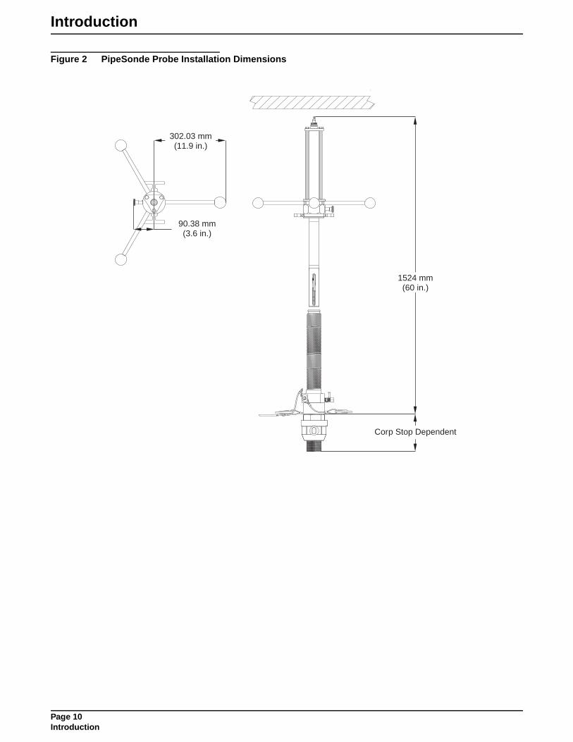
Introduction
Figure 2 PipeSonde Probe Installation Dimensions
Corp Stop Dependent
90.38 mm(3.6 in.)
302.03 mm(11.9 in.)
1524 mm(60 in.)
Page 10Introduction

INSTALLATION
Page 11INSTALLATION
DANGERSome of the following manual sections contain information in the form of warnings, cautions and notes that require special attention. Read and follow these instructions carefully to avoid personal injury and damage to the instrument. Only personnel qualified to do so, should conduct the installation/maintenance tasks described in this portion of the manual.
DANGERCertains des chapitres suivants de ce mode d’emploi contiennent des informations sous la forme d’avertissements, messages de prudence et notes qui demandent une attention particulière. Lire et suivre ces instructions attentivement pour éviter les risques de blessures des personnes et de détérioration de l’appareil. Les tâches d’installation et d’entretien décrites dans cette partie du mode d’emploi doivent être seulement effectuées par le personnel qualifié pour le faire.
PELIGROAlgunos de los capítulos del manual que presentamos contienen información muy importante en forma de alertas, notas y precauciones a tomar. Lea y siga cuidadosamente estas instrucciones a fin de evitar accidentes personales y daños al instrumento. Las tareas de instalación y mantenimiento descritas en la presente sección deberán ser efectuadas únicamente por personas debidamente cualificadas.
GEFAHREinige der folgenden Abschnitte dieses Handbuchs enthalten Informationen in Form von Warnungen, Vorsichtsmaßnahmen oder Anmerkungen, die besonders beachtet werden müssen. Lesen und befolgen Sie diese Instruktionen aufmerksam, um Verletzungen von Personen oder Schäden am Gerät zu vermeiden. In diesem Abschnitt beschriebene Installations- und Wartungsaufgaben dürfen nur von qualifiziertem Personal durchgeführt werden.
PERICOLOAlcune parti di questo manuale contengono informazioni sotto forma d’avvertimenti, di precauzioni e di osservazioni le quali richiedono una particolare attenzione. La preghiamo di leggere attentivamente e di rispettare quelle istruzioni per evitare ogni ferita corporale e danneggiamento della macchina. Solo gli operatori qualificati per l’uso di questa macchina sono autorizzati ad effettuare le operazioni di manutenzione descritte in questa parte del manuale.

Section 2 Installation
2.1 Unpacking the InstrumentRemove PipeSonde Probe from its shipping carton and inspect it for any visible damage. Contact Hach Customer Service at 1-800-604-3493 if any items are missing or damaged.
2.2 Pipe Installation
DANGERAll plumbing connections should be made by a qualified professional.
A space of approximately 60 inches is required from the pipe to the nearest wall/ceiling for proper installation of the adapter and insertion of the PipeSonde Probe (see Figure 2 on page 10).
DANGERDo not use the PipeSonde Probe in applications where pressures can exceed 300 PSI.
1. Install the 2-inch Corporation Stop into the water main pipe (minimum pipe size is 8 in. diameter). See Table 1 for recommended Corporation Stops. The manufacturer recommends using a Ford Series Tapping Saddle (S90, S70, 202B, 202BS, F202, FC202, or equivalent) when installing the Corporation Stop (Figure 3). Select a tapping saddle with a wide band or strap for extra support for high loads.
2. Install the Corporation stop between 20 degrees down from vertical and 20 degrees from horizontal to ensure the probe is properly inserted into the water stream when the pipe is not completely full (Figure 4).
3. Apply the supplied Loc-tite high-strength sealant (Cat.No. 007187) to the threads on the Corporation Stop.
4. Make sure the Teflon Seal is seated on the Corporation Adapter and screw the Corporation Adapter to the Corporation Stop. The manufacturer supplies multiple Teflon Seals for different Corporation Stop brands, see Parts and Accessories on page 53. Use a torque wrench to tighten the Corporation Adapter to approximately 20 ft/lb of torque. Do not overtighten or damage to the seal may occur.
Table 1 Recommended Corporation Stops
Corporation Stop Part Number
Ford FB600-7 or FB7007-7
AY McDonald 4701A-2 or 4704B-2
Mueller B25025
Page 13Installation

Installation
Figure 3 Attaching the Corporation Adapter
Figure 4 Pipe Installation
1. Corporation Adapter 5. Tapping Saddle
2. Teflon Seal 6. Relief Valve
3. Apply Loctite 7. Corporate Stop Valve
4. Corporation Stop
1
2
3
4
5
7
6
20°
20°
AcceptablePlacement
20°
20°
AcceptablePlacement
Page 14Pipe Installation

Installation
2.3 Inserting the PipeSonde In-Pipe Probe
DANGERFailure to properly attach the lanyard cable may result in serious injury.
1. Attach all three handles to the PipeSonde Probe (Figure 5).
2. Remove the calibration cup from the Sonde and attach the sensor guard (see Figure 23 on page 40). Keep the calibration cup for later use during maintenance and calibration.
Note: Make sure the turbidity sensor has a clear optical path through one of the slots in the sensor guard.
3. Open the relief valve (Figure 3).
4. Make sure the inside of the corporation adapter and the probe is clean before insertion. Remove any debris with a clean cloth.
5. Insert the sensor-end of the Sonde into the Corporation Adapter until the Nut on the Sonde reaches the top of the Corporation Adapter threads (Figure 6).
6. Attach both lanyard cables to the aluminum lanyard bracket (Figure 6).
7. Insert the PipeSonde Probe into the pipe by rotating the handles clockwise. After approximately 5 rotations the locking pin will engage (clicking sound) preventing the Sonde from rotating.
8. Close the relief valve (Figure 3).
CAUTIONAttempting to continue installation of the probe without opening the Corporation valve may cause serious damage to the sensor, adapter, and valve.
9. Open the Corporation Stop Valve to prevent the sensors from hitting the closed valve and becoming damaged.
10. Pull the Locking Knob (Figure 5) and continue rotating the handles clockwise for approximately half a rotation. This disengages the Locking Pin and allows continuation of the insertion process.
11. Continue rotating the handles until the Nut reaches the bottom of the Corporation Adapter threads.
12. Align the nut flat to allow the insertion of the Quick Connect Pin into the hole on the Corporation Adapter to prevent the Nut from disengaging (Figure 7).
13. Attach the Data Cable to the end of the Sonde.
14. Remove the handles to prevent tampering.
Page 15Inserting the PipeSonde In-Pipe Probe

Installation
Figure 5 Inserting the Sonde
1. Data and Battery Cable Connection 6. Lanyard
2. PipeSonde Probe 7. Handles (3)
3. Aluminum Lanyard Bracket 8. Locking Knob
4. Sensor Guard 9. Nut
5. Corporation Adapter 10. Relief Valve
1
2
4
5
7
8
3
6
9
10
Page 16Inserting the PipeSonde In-Pipe Probe

Installation
Figure 6 Attaching the Lanyard Cables
Figure 7 Inserting the Quick-connect Pin
1. PipeSonde Probe 3. Attach lanyard cables to the lanyard bracket.
2. Lanyard Bracket 4. Make sure lanyard cables are locked in place
1. Nut 2. Quick-connect Pin 3. Corporation Adapter 4. Lanyard Cable
2
1
3 4
1
2
3
4
Page 17Inserting the PipeSonde In-Pipe Probe

Installation
2.4 Removing the PipeSonde In-Pipe Probe
DANGERFailure to properly attach the lanyard cables may result in serious injury.
1. Make sure the Lanyard Cables are securely connected to the Nut.
2. Remove the Data Cable from the end of the PipeSonde Probe.
3. Attach all three handles to the PipeSonde Probe, if not already installed.
4. Remove the Quick Connect Pin from the hole on the Corporation Adapter.
5. Rotate the handles counter-clockwise until the Locking Pin is engaged (clicking sound).
DANGERIf water sprays out through the top, the valve is not closed. Close the valve. Failure to close the valve may cause serious injury.
6. Close the Corporation Stop Valve.
7. Open the relief valve (Figure 5).
8. Pull the Locking Knob and continue rotating the handles counterclockwise for approximately half a rotation.
9. Rotate the handles until the Nut reaches the top of the Corporation Adapter threads.
10. Make sure the Corporation Stop Valve is turned off, and remove the Lanyard Cables from the lanyard bracket.
11. Pull the Sonde away from the base of the Corporation Adapter.
2.5 Connecting Power to the PipeSonde In-Pipe Probe1. Attach the data and power cable connector (Cat. No. 007185) to the end
of the Sonde (Figure 5). Align the cable connector indicator dot to the largest pin on the Sonde connector. The Sonde will beep to indicate a proper connection. Do not force the connection or damage to the connector pins may occur.
2. Connect the 4-pin female connector to the external battery pack or ac adapter.
Table 2 Power Supply Options
Power Supply Catalog Number
115 V ac Adapter 013450
110 V Battery Pack 011050
Battery Adapter Cable 011530HY
Solar Power Configuration See Parts and Accessories on page 53
Page 18Removing the PipeSonde In-Pipe Probe

Installation
Figure 8 Battery Supply Options
2.5.1 Solar Power Connections
2.5.1.1 Mounting the Units
Note: To maintain the integrity of the NEMA rated enclosure, seal empty knockouts or through-holes using NEMA approved strain reliefs and strain relief plugs (Cat. No. 9711300 or 9711400).
Mount the regulator and/or junction box near a PipeSonde Probe or a 900 MAX Series Sampler. The enclosures are rated NEMA 4X (IP66) and designed to mount easily to a wall, pole, or panel. Allow at least one inch of clearance on the top sides and a minimum of six inches on the bottom. Disassembly is not required for pole or wall mounting, and minimal disassembly is required for panel mounting.
A mounting bracket is supplied for securing the enclosure to a horizontal or vertical pole (or similar structure) or to a wall. The pole must have an outside diameter of ¾- to 2-inches and must be capable of supporting at least five (5) pounds.
Make sure all necessary knock-outs are removed before mounting the junction box.
Page 19Connecting Power to the PipeSonde In-Pipe Probe

Installation
Figure 9 Mounting Bracket Dimensions
Figure 10 Mounting Bracket
Page 20Connecting Power to the PipeSonde In-Pipe Probe

Installation
Pole Mounting 1. Obtain two ¼–20 x 2.843 U-bolts and nuts (Cat. No. 5141000).
2. Remove knock-outs if necessary.
3. Press the back of the mounting bracket against a pole in the proper mounting position, either vertically or horizontally.
4. Place the curve of one U-bolt behind the pole, and insert the threaded ends of the bolt through two of the center holes on the mounting bracket (see Figure 11).
5. Secure the two nuts with a wrench, and repeat steps 1–3 on the opposite end of the bracket.
Figure 11 Pole Mounting
Wall Mounting1. Remove knock-outs if necessary.
2. Remove the mounting bracket from the back of the enclosure.
3. Use the bracket as a template or use the dimensions shown in Figure 9 to mark positions on the wall for four of the eight screw holes.
4. Reconnecting the mounting bracket to the device is necessary (Figure 10).
5. Drill pilot holes in the marked positions for four ¼-inch screws.
6. Use four ¼-inch, hex-head or pan-head screws to secure the bracket and device to the wall.
Panel Mounting1. Remove knock-outs if necessary.
2. Use a Phillips-head screwdriver to remove the four screws holding the mounting bracket onto the back of the junction box. The wall mount bracket is not needed for panel mounting.
3. Use a flat-blade screwdriver to loosen the screws on the enclosure face.
4. Lift the face off the junction box and set it aside.
5. Measure the panel hole using the dimension information given in Figure 12. Mark the panel for placement of three #10 pan-head screws.
6. Cut out the panel hole and drill three pilot holes for the screws (see Figure 13).
Page 21Connecting Power to the PipeSonde In-Pipe Probe

Installation
7. Fit the enclosure into the panel hole and secure it with three #10 pan-head screws.
8. Ensure the gasket is properly seated in the enclosure cover and tighten the screws (10 in.-lb (1.1 n-m) maximum). Do not overtighten the screws.
Figure 12 Panel Mount Dimensions (For Reference Only, Not to Scale)
V-Holes for #1 0 Pan-head screws
3 Places
0.16" (4.06 mm)-~_ I" i
r--------------~~~-------------~
I 7.30"
(185.42 mm)
........................ (1) .. CUI-OUI
3.65" (92.71 mm)
I
-~
3.65" (92.71 mm) ---J - ..................................................... 7.30" (185.42 mm)-
L O.2B' (7.11 mm) 2 Places
Page 22Connecting Power to the PipeSonde In-Pipe Probe

Installation
Figure 13 Panel Mounting
2.5.1.2 Mounting the Solar Panel Refer to the manufacturer’s guidelines for solar panel installation and mounting instructions.
2.5.1.3 Wiring the Solar Panel to the Regulator1. Attach two spade connectors (Cat. No. 4129700) to the bare leads of the
15 ft. cable attached to the solar panel.
2. Feed the cable through the strain relief on the bottom of the regulator.
3. Connect to the screw terminals as shown in Figure 14.
Figure 14 Wiring the Solar Panel to the Regulator
To Solar PanelTo Thermal Protection Sensor
Red (+)positive
Fuse Informationand wiring label
Black (–)negative
Page 23Connecting Power to the PipeSonde In-Pipe Probe

Installation
2.5.1.4 Setting Up a PipeSonde Probe (Only)The table below lists the cables used to set up a PipeSonde Probe (only):
1. Open the regulator enclosure.
2. Wire the solar panel unit to the regulator, refer to Figure 14.
Note: Positive wires are red or white and negative wires are black. Always connect wires to the properly labeled polarity.
3. Connect the PipeSonde Probe Solar Power cable connector to the PipeSonde Probe.
4. Remove the plug from the fourth hole in the regulator enclosure.
5. Remove the nut from the PipeSonde Probe Solar Power cable strain relief and feed the cable through the fourth hole on the regulator. Thread the nut over the wires and tighten to secure. Connect the spade terminals to the screw terminals as shown in Figure 15.
CAUTIONDeep cycle batteries must be housed in a ventilated enclosure to ensure that combustible gases that occur during charging operations are released.
6. Attach the pre-wired Thermal Protection Sensor to the side of the battery source (Cat. No. 1414 or customer-supplied deep cycle battery) with the supplied adhesive-backed foam tape. The Thermal Protection Sensor continually controls the battery temperature and charge threshold and shuts down the regulator in the event of overheating.
Note: Do not attach the thermal protection sensor to damaged batteries.
7. Remove the nut on the battery cable strain relief and feed the battery cable through the third hole on the regulator. Thread the nut over the wires and tighten to secure. Connect spade terminals to the screw terminals. Refer to Figure 15.
8. Connect the appropriate end of the battery cable to the appropriate battery type. Figure 15 shows a PipeSonde Probe with a 1414 gel battery.
9. Locate the two fuse holders and unscrew to open. Place an 8 amp, 125 V, 5x20 mm fuse (Cat. No. 8711100) into each holder and screw the holders back together.
10. Close the regulator enclosure with the gasket and cover properly seated and tighten all strain relief fittings.
Cable DescriptionPart
Number
1414 Battery CableStrain relief and a two-conductor wire with spade terminals on one end and a connector on the other end.
8710700
Deep Cycle Battery Cable Strain relief and a two-conductor wire with spade terminals on both ends. 8710900
PipeSonde Probe Solar Power Cable
Strain relief fitting and a two-conductor wire with spade terminals on one end and a connector on the other end.
007191
Page 24Connecting Power to the PipeSonde In-Pipe Probe

Installation
Figure 15 Setting up the a PipeSonde Probe with Gel Battery (Cat. No. 1414)
1414 Gel Battery
WARNING
USE OF IMPROPER CHARGER MAYDAMAGE THE BATTERY AND/ORRESULT IN PERSONAL INJURY.
Solar Panel(Panel Brackets
Mounting Hardware)
Regulator
Thermal Protection Sensor
Red and White to PositiveBlack to Negative
Page 25Connecting Power to the PipeSonde In-Pipe Probe

Installation
2.5.1.5 Setting Up a Sigma 900 MAX Series Sampler with a PipeSonde ProbeThe table below lists the cables needed to set up a Sigma 900 MAX Series Sampler and a PipeSonde Probe.
1. Open the regulator enclosure.
2. Wire the solar panel unit to the regulator, refer to Figure 14 on page 23.
Note: Positive wires are red or white and negative wires are black. Always connect wires to the properly labeled polarity.
3. Attach the pre-wired Thermal Protection Sensor to the side of the battery source with adhesive-backed foam tape. The Thermal Protection Sensor continually controls the battery temperature and charge threshold and shuts down the regulator in the event of overheating.
Note: Do not attach the thermal protection sensor to damaged batteries.
CAUTIONDeep cycle batteries must be housed in a ventilated enclosure to ensure that combustible gases that occur during charging operations are released.
4. Connect the sampler cable connector to the 900 MAX Series sampler and connect the sampler cable ring lugs to the deep cycle battery.
5. Remove the nut on the battery cable strain relief and feed battery cable wires through the third hole on the regulator. Thread the nut over the wire and tighten to secure. Connect the spade terminals to the screw terminals. Refer to Figure 16.
6. Connect the battery cable ring lugs to the deep cycle battery.
7. Connect the PipeSonde Probe Solar Power cable connector to the PipeSonde Probe.
8. Remove the plug from the fourth hole on the regulator.
9. Remove the nut from the PipeSonde Probe Solar Power cable strain relief and feed the PipeSonde Probe Solar Power cable wires through the fourth hole on the regulator. Thread the nut over the wires and tighten to secure. Connect the spade terminals to the screw terminals as shown in Figure 16.
10. Locate the two fuse holders and unscrew to open. Place an 8 amp, 125 V, 5x20 mm fuse (Cat. No. 8711100) into each fuse holder and screw the holders back together.
11. Close the regulator enclosure with the gasket and cover properly seated and tighten all strain relief fittings.
Cable DescriptionPart
Number
Deep Cycle Battery CableStrain relief and a two-conductor wire with spade terminals on one end and ring lugs on the other end.
8710900
PipeSonde Probe Solar Power Cable
Strain relief fitting and a two-conductor wire with spade terminals on one end and a connector on the other end.
007191
Sampler Cable Ring lugs on one end, two-conductor wire and connector on the other end. 8711000
Page 26Connecting Power to the PipeSonde In-Pipe Probe
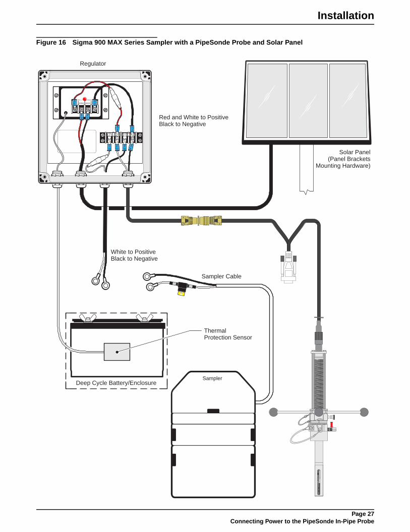
Installation
Figure 16 Sigma 900 MAX Series Sampler with a PipeSonde Probe and Solar Panel
Deep Cycle Battery/Enclosure
Solar Panel(Panel Brackets
Mounting Hardware)
Sampler Cable
ThermalProtection Sensor
Sampler
White to PositiveBlack to Negative
Regulator
Red and White to PositiveBlack to Negative
Page 27Connecting Power to the PipeSonde In-Pipe Probe

Installation
2.6 Using the SDI-12 Adapter Cable to Connect to a DataloggerSDI-12 is an industry-originated, serial digital interface bus designed to allow an operator to connect a wide variety of transducers (meteorological, hydrological, water quality, etc.) to a single SDI-12 datalogger with a single cable bus.
The PipeSonde In-Pipe Probe is compatible with SDI-12 V1.2. A copy of the specification can be found at www.sdi-12.org. The optional SDI-12 Interface Adapter is required to operate the PipeSonde Probe with an SDI-12 Datalogger.
Note: All four wires (two grounds) must be connected for correct SDI-12 operation.
A label on the SDI-12 Interface Adapter shows the pinout in Figure 17.
1. Connect the data cable to the SDI-12 Interface Adapter connector.
2. Disconnect power from the PipeSonde Probe.
3. Connect the bare wires at the end of the SDI-12 Interface Adapter to the appropriate connections on the SDI-12 datalogger. Follow the label on the SDI-12 Interface Adapter.
Figure 17 SDI-12 Cable
Consult the SDI-12 datalogger manual for information on how to connect the SDI-12 Interface Adapter. Refer to Appendix A on page 49 for the SDI-12 command summary.
2.7 Using the Optional RS232 to RS485 Converter KitAn optional RS232 to RS485 converter is available for the PipeSonde Probe. This option allows the PipeSonde Probe to connect to a 2-wire or 4-wire RS485 bus. For more information refer the instructions supplied with the RS232 to RS485 Converter Kit.
2.8 Connecting a TOC Analyzer to the PipeSonde ProbeRefer to Figure 18 and the following steps for a pressurized sampling with a Hach TOC Analyzer.
1. Remove the plug on the PipeSonde Sampler/TOC port.
2. Connect pressure regulator to the Sampler/TOC port using a nipple.
3. Connect the sampler tubing to the compression fitting (Figure 18).
Table 3 SDI-12 Pinouts
Pin Number Wire Color*
* Wire color is valid only for this cable (Cat. No 007139).
SDI-12 Function
1 Brown +12 V dc
2 Red Ground
3 Orange SDI-12 Data
Shield Yellow SDI-12 Ground
YellowOrangeRedBrown
Page 28Using the SDI-12 Adapter Cable to Connect to a Datalogger

Installation
Figure 18 Connecting TOC Analyzer
1. Corporation Adapter 5. Pressure Regulator
2. Nipple 6. 1/8-in. Compression Fitting
3. NPT Adapter (only with certain regulators) 7. ¼-in. OD Tubing
4. NPT Adapter (only with certain regulators)
CAUTIONTHIS UNIT USES
SODIUM PERSULPHATE ANDPHOSPHORIC ACID. EXERCISE
APPROPRIATE SKIN ANDEYE PRECAUTIONS WHEN
OPERATING.
THIS UNIT USESSODIUM PERSULPHATE AND
PHOSPHORIC ACID. EXERCISEAPPROPRIATE SKIN AND
EYE PRECAUTIONS WHENOPERATING.
WARNINGTHE UV LAMPS IN THISASSEMBLY OPERATE AT UPTO 3000 VAC. ISOLATE THEINCOMING POWER SUPPLYBEFORE SERVICING.
THE UV LAMPS IN THISASSEMBLY OPERATE AT UPTO 3000 VAC. ISOLATE THEINCOMING POWER SUPPLYBEFORE SERVICING.
DO NOT LOOK DIRECTLY ATLAMPS WHILE OPERATING. THEYCAN PERMANENTLY DAMAGEEYES AND SKIN.
DO NOT LOOK DIRECTLY ATLAMPS WHILE OPERATING. THEYCAN PERMANENTLY DAMAGEEYES AND SKIN.
THE LAMPS OBTAIN MERCURY.EXERCISE EXTREME CAUTIONIN HANDLING.
THE LAMPS OBTAIN MERCURY.EXERCISE EXTREME CAUTIONIN HANDLING.
OLD LAMPS MUST BE DISPOSEDOF IN AN APPROPRIATEMANNER IF LAMPS BREAK,TAKE ALL PRECAUTIONSAPPROPRIATE TO A MERCURYSPILL.
OLD LAMPS MUST BE DISPOSEDOF IN AN APPROPRIATEMANNER IF LAMPS BREAK,TAKE ALL PRECAUTIONSAPPROPRIATE TO A MERCURYSPILL.
Escape
Program ModeProgram Mode
CtrlEnterEnter
A1 A2 F
1 2 3
5
Drain
4
6 7
Page 29Connecting a TOC Analyzer to the PipeSonde Probe

Installation
2.9 Connecting a Sigma 900 MAX Series Sampler to the PipeSonde Probe
CAUTIONFailure to reduce pressure to less than 10 psi will result in the damage of the sampler.
Pressurized sampling uses a 3-way solenoid valve to draw a sample and then drains the sample by purging.
When the 3-way solenoid valve is at rest, the solenoid valve is closed and samples can drain from the sampler to the floor drain. During the purge cycle the solenoid valve is closed and the pump purges to drain the line from the sampler. During a sample cycle the 3-way solenoid valve opens to allow the sample to be taken from the pipe. See Figure 19 for an example of valve functions.
Figure 19 Valve Functions
The sampler can be located away from the main pipe, but distance is limited by the 25-ft solenoid cable length.
Refer to Figure 21 and the following steps for pressurized sampling with a Sigma 900 MAX Series Sampler:
1. Remove the plug on the PipeSonde Sampler/TOC port.
2. Connect pressure regulator to the PipeSonde Sampler/TOC port using a nipple.
3. Connect the 3-way valve normally closed port to the ¼-in. NPT pressure regulator output using a nipple (Figure 20).
4. Connect the 3-way valve input port to the 3/8-in. sampler tubing(Figure 21).
5. Connect the 3-way valve normally open port to a 3/8-in. tubing running to the floor drain. (Figure 20 and Figure 21).
6. Solder and heat shrink the solenoid cable wires to the 3-way solenoid valve wires.
7. Connect the solenoid output cable to the sampler.
Figure 20 3-way Valve Ports (Cat. No. 007150)
A B C
To DrainTo Drain
From SamplerPump
From SamplerPump
From SamplerPump
Reset Purge Sample
1
2
3
Port 1 = NCPort 2 = INPort 3 = NO
Page 30Connecting a Sigma 900 MAX Series Sampler to the PipeSonde Probe

Installation
Figure 21 Connecting a Sigma Sampler
1. Corporation Adapter 4. NPT Adapter (only with certain regulators)
7. Pressure Regulator with Pressure Gauge
2. Nipple 5. 3-way valve 8. Nipple
3. NPT Adapter (only with certain regulators)
6. Barb Fitting 9. 3/8-in. Tubing
21 9
7 8
Sampler
Solenoid Output Cable
Drain
3/8 -in. Tubing
Black
Clear
3
4 5 6
Page 31Connecting a Sigma 900 MAX Series Sampler to the PipeSonde Probe

Visit http: //www.hach.com

OPERATION
Page 33OPERATION
DANGERHandling chemical samples, standards, and reagents can be dangerous. Review the necessary Material Safety Data Sheets and become familiar with all safety procedures before handling any chemicals.
DANGERLa manipulation des échantillons chimiques, étalons et réactifs peut être dangereuse. Lire les Fiches de Données de Sécurité des Produits (FDSP) et se familiariser avec toutes les procédures de sécurité avant de manipuler tous les produits chimiques.
PELIGROLa manipulación de muestras químicas, estándares y reactivos puede ser peligrosa. Revise las fichas de seguridad de materiales y familiarícese con los procedimientos de seguridad antes de manipular productos químicos.
GEFAHRDas Arbeiten mit chemischen Proben, Standards und Reagenzien ist mit Gefahren verbunden. Es wird dem Benutzer dieser Produkte empfohlen, sich vor der Arbeit mit sicheren Verfahrensweisen und dem richtigen Gebrauch der Chemikalien vertraut zu machen und alle entsprechenden Materialsicherheitsdatenblätter aufmerksam zu lesen.
PERICOLOLa manipolazione di campioni, standard e reattivi chimici può essere pericolosa. La preghiamo di prendere conoscenza delle Schede Techniche necessarie legate alla Sicurezza dei Materiali e di abituarsi con tutte le procedure di sicurezza prima di manipolare ogni prodotto chimico.

Section 3 Operation
The WDM PipeSonde™ In-pipe Probe uses Hydras 3 LT or a Surveyor 4a to set up parameters and calibrate the sensors.
Figure 22 Operations Setup
3.1 Parameter Setup
3.1.1 Using the Surveyor 4a for Parameter SetupFor more information on the Surveyor 4a, refer to the User Manual (Cat. No. 00719618).
1. Attach the power and data cable to the Sonde. Attach the 9-pin connector to the Surveyor 4a.
2. Turn on the Surveyor 4a. Wait approximately 10 seconds for initialization.
3. Press SETUP/CAL. Press SETUP. Press SONDE.
4. Highlight Parameters and press SELECT.
5. Use the up and down arrow keys to highlight the appropriate parameter and press SELECT.
6. Highlight the appropriate function and press SELECT. A configuration screen will be displayed. Depending on the application, use the ARROW keys to change the function, press SELECT and DONE to finish.
Surveyor 4aWindows 98, NT, 2000, XP
Calibration cable
To Power Supply
Page 35Operation
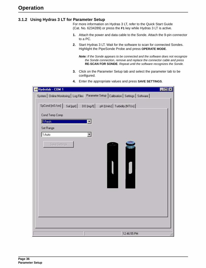
Operation
3.1.2 Using Hydras 3 LT for Parameter SetupFor more information on Hydras 3 LT, refer to the Quick Start Guide (Cat. No. 6234289) or press the F1 key while Hydras 3 LT is active.
1. Attach the power and data cable to the Sonde. Attach the 9-pin connector to a PC.
2. Start Hydras 3 LT. Wait for the software to scan for connected Sondes. Highlight the PipeSonde Probe and press OPERATE MODE.
Note: If the Sonde appears to be connected and the software does not recognize the Sonde connection, remove and replace the connector cable and press RE-SCAN FOR SONDE. Repeat until the software recognizes the Sonde.
3. Click on the Parameter Setup tab and select the parameter tab to be configured.
4. Enter the appropriate values and press SAVE SETTINGS.
Page 36Parameter Setup

Operation
3.1.3 Specific Conductance Parameter SetupFor specific conductance set the following functions using Hydras 3 LT or the Surveyor 4a:
• Select the function to use to compute specific conductance (1:Fresh, 2:Salt, 3:StdMth, 4:None, or 5:Custom).
• Fresh (default) is based on the manufacture’s freshwater temperature compensation. This function is derived from 0.01N KCI: f(T) = c1T5 + c2T4 + c3T3 + c4T2 + c5T + c6, where c1= 1.4326 x 10⁻⁹, c2= –6.0716 x 10⁻⁸, c3= –1.0665 x 10⁻⁵, c5= –5.3091 x 10⁻², c6= 1.8199.
• Salt is based on the manufacturer’s saltwater compensation. f(T) = c1T7 + c2T6 + c3T5 + c4T4 + c5T3 + c6T2 + c7T + c8 where c1=1.2813 x 10⁻¹¹, c2 = –2.2129 x 10⁻⁹, c3 = 1.4771 x 10⁻⁷, c4 = –4.6475 x 10⁻⁶, c5 = 5.6170 x 10⁻⁵, c6 = 8.7699 x 10⁻⁴, c7 =–6.1736 x 10⁻², c8 =1.9524.
• StdMth will remove any temperature compensation, so the readings are equivalent to conductivity: f(T)=1.
• Custom will provide a compensation function that the user can define according to the following function: f(T)= aT7 + bT6 + cT5 + dT4 + eT3 + fT2 + gT + h.
• Select the Set Range (1:Auto, 2:High, 3:Mid, or 4:Low).
• Auto (default) allows the multiprobe to automatically select the most appropriate range to measure conductivity. The multiprobe will dynamically change the range based on the current measurement conditions over 0–100 mS/cm. The resolution of the displayed data will also change to accommodate the current range in use.
• High, Mid, and Low force the multiprobe to measure conductivity using a fixed range. If low range is selected, the readings will indicate an over-ranged condition for values above 1.5 mS/cm. The Mid range will over-range at 15 mS/cm. These choices also force the displayed readings to a fixed point or constant resolution format primarily only needed for certain SDI-12 data loggers. Otherwise, it is best to always select the Auto choice as this gives the best accuracy and performance for the conductivity sensor.
• Select the computation method for salinity (1:2311 or 2:StdMth).
• 2311 (default): salinity will be computed using an algorithm adapted from the United States Geological Survey Water-Supply Paper 2311 titled “Specific Conductance: Theoretical Considerations and Application to Analytical Quality Control”. This salinity function is only defined from salinities in the 30 to 40 ppt range (mild concentrations and dilutions of sea water). This salinity function uses specific conductance values C in mS/cm compensated.
Salinity = c1C4 + c2C3 + c3C2 + c4C + c5 where c1 = 5.9950 x 10⁻⁸, c2= –2.3120 x 10⁻⁵, c3 = 3.4346 x 10⁻³, c4 = 5.3532 x 10⁻¹, c5 = –1.5494 x 10⁻².
Page 37Parameter Setup

Operation
• StdMth: salinity will be computed using the Practical Salinity Scale (1978). This algorithm is defined for salinities ranging from 2 to 42 ppt and uses conductivity values corrected to 15 °C, regardless of the compensation function selected for specific conductance. This algorithm is described in section 2520B of “Standard Methods for the Examination of Water and Wastewater”, 18th edition.
3.1.4 Dissolved Oxygen Parameter SetupFor dissolved oxygen, set the following functions using Hydras 3 LT or the Surveyor 4a:
• Enable or Disable Salinity Compensation.
3.1.5 pH Parameter SetupFor pH, set the following functions using Hydras 3 LT or the Surveyor 4a:
• Select either 2 or 3 calibration points.
3.1.6 Turbidity Parameter SetupFor Turbidity, set the following functions using Hydras 3 LT or the Surveyor 4a:
• Select the Set Range (1:Auto, 2:High, 3:Low). Select Auto to report turbidity values from 0 to 1000. Samples over 1000 will indicate an overange. If the turbidity reading is less than 100.0, then one decimal point of accuracy is displayed. If the turbidity reading is more than 100.0 then the decimal point is removed from the displayed results. Select low range to report turbidity values from 0 to 100. Low range will always display the decimal point and samples over 100 will indicate an over-range. Select High to report turbidity values from 0 to 1000. The decimal point precision will be removed and samples over 1000 will indicate an over-range error.
3.2 Calibration
3.2.1 Calibrating the Sensors Using Hydras 3 LTFor more information on Hydras 3 LT, refer to the Quick Start Guide (Cat. No. 6234289) or press the F1 key while Hydras 3 LT is active.
1. Attach the power and data cable to the Sonde. Attach the 9-pin connector to a PC.
2. Start Hydras 3 LT. Wait for the software to scan for connected Sondes. Highlight PipeSonde Probe and press OPERATE MODE.
Note: If the Sonde appears to be connected and the software does not recognize the Sonde connection, remove and replace the connector cable and press RE-SCAN FOR SONDE. Repeat until the software recognizes the Sonde.
3. Click on the Calibration Tab and click on the parameter to be calibrated.
4. Enter the calibration values and click CALIBRATE.
Page 38Calibration

Operation
3.2.2 Calibrating the Sensors Using the Surveyor 4aFor more information on the Surveyor 4a, refer to the User Manual (Cat. No. 00719618).
1. Attach the power and data cable to the Sonde. Attach the 9-pin connector to the Surveyor 4a.
2. Turn on the Surveyor 4a. Wait approximately 10 seconds for initialization.
3. Press SETUP/CAL. Press CALIBRATION. Press SONDE.
4. Use the up and down arrow keys to highlight the appropriate parameter and press SELECT.
5. Highlight the function to program and press SELECT. A configuration screen will be displayed. Depending on the application, use the ARROW keys to change the function, press SELECT, and DONE to finish the configuration.
Page 39Calibration
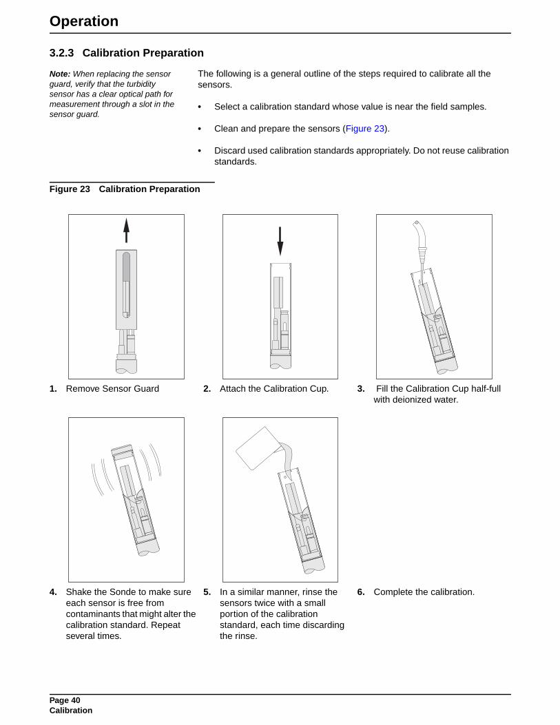
Operation
3.2.3 Calibration Preparation
Note: When replacing the sensor guard, verify that the turbidity sensor has a clear optical path for measurement through a slot in the sensor guard.
The following is a general outline of the steps required to calibrate all the sensors.
• Select a calibration standard whose value is near the field samples.
• Clean and prepare the sensors (Figure 23).
• Discard used calibration standards appropriately. Do not reuse calibration standards.
Figure 23 Calibration Preparation
1. Remove Sensor Guard 2. Attach the Calibration Cup. 3. Fill the Calibration Cup half-full with deionized water.
4. Shake the Sonde to make sure each sensor is free from contaminants that might alter the calibration standard. Repeat several times.
5. In a similar manner, rinse the sensors twice with a small portion of the calibration standard, each time discarding the rinse.
6. Complete the calibration.
Page 40Calibration

Operation
3.2.4 Temperature Sensor CalibrationThe temperature sensor is factory-set and does not require recalibration.
3.2.5 Specific Conductance Calibration Specific conductance requires a two-point calibration. Calibrate the sensor to zero and then to the slope buffer.
1. Pour the specific conductance standard to within a centimeter of the top of the Calibration Cup.
2. Make sure there are no bubbles in the measurement cell of the specific conductance sensor.
3. Enter the SpCond standard for mS/cm or µS/cm using Hydras 3 LT software or a Surveyor 4a.
3.2.6 Dissolved Oxygen Sensor Calibration
3.2.6.1 DO %Saturation Calibration Standard (Saturated-Air Method)
Note: Calibration of DO %Saturation also calibrates DO mg/L.
1. Fill the Calibration Cup with deionized or tap water (specific conductance less than 0.5 mS/cm) until the water is just below the membrane O-ring.
2. Carefully remove any water droplets from the membrane with the corner of a tissue.
Note: DO can also be calibrated in a well-stirred bucket of temperature-stable, air-saturated water. This situation more closely resembles the actual field measurement conditions, but is more difficult to accomplish reliably.
3. Turn the black calibration cup cover upside down (concave upward) and lay it over the top of the Calibration Cup.
4. Determine the barometric pressure for entry as the calibration standard.
5. Enter the barometric pressure in millimeters of Mercury (mmHg) at the site using Hydras 3 LT software or a Surveyor 4a.
3.2.6.2 DO mg/L Calibration Standard (Known Concentration Method)
Note: Calibration of DO mg/L also calibrates DO %Saturation.
1. Immerse the sensor in a water bath for which the DO concentration in mg/L is known (for instance, by Winkler titration). This calibration method is more difficult to perform than the saturated-air method but can yield a higher accuracy if the "known" DO concentration is highly accurate.
2. Enter the barometric units (mmHg) using Hydras 3 LT or a Surveyor 4a.
3. Enter the DO units in mg/L using Hydras 3 LT or a Surveyor 4a.
Note: If there is a change in barometric pressure after calibration (for instance, if barometric pressure drops as you move the calibrated Transmitter to a higher elevation for deployment), the readings for DO %Saturation will not be correct. You must enter a new barometric pressure. However, the readings for DO mg/L will be correct regardless of changes in barometric pressure.
3.2.7 Pressure Sensor Calibration
Note: The density of water varies with its specific conductance. Pressure readings are corrected for specific conductance.
1. Enter zero for the standard when located near the pipe using Hydras 3 LT or a Surveyor 4a.
Page 41Calibration

Operation
3.2.8 Turbidity Sensor Calibration
Note: DO NOT SHAKE the StableCal solutions prior to calibration as this will introduce air bubbles which will impact the calibration.
Hach recommends calibrating the turbidity sensor in a vessel with at least a 2-inch clearance between the vessel wall and the optical path of the lenses. It is not recommended to use the calibration cup for calibration.
Calibration consists of setting the zero point using low-turbidity water and setting the slope using a solution of known turbidity. The slope standard should be close to the expected NTU value of the deployment site.
2-point CalibrationFor standard applications, the NTU Calibration can use any 2-points between 0 and 20 NTU to create a single zone of linear interpolation. Hach StableCal standards of <0.1, 1, 10, and 20 NTU are available to create a linear interpolation zone as desired.
1. Rinse the sensor and the vessel with low-turbidity water (prepared by running distilled water through a 0.2-micron filter) several times and dry with a lint-free cloth or compressed air. Any residue or fluids left behind will affect the calibration accuracy.
2. Fill the vessel with StablCal standard, starting with the <0.1 NTU solution. To prevent excess bubbles, slowly pour the standard down the side of the vessel.
Note: For the “zero” point, the Hach StablCal standard is listed at <0.1 NTU, which is true for controlled laboratory environments. Enter a value between 0.3–0.6 for the “zero” point, depending on the cleanliness of the environment and cup.
3. Wait for the NTU values to stabilize, 30 seconds minimum, and enter the value of the turbidity standard used.
4. Calibrate using turbidity standards from low to high NTU values, for example <0.1, 1, 10, and then 20 NTU. Rinse the vessel and the sensor twice with low-turbidity water between each calibration point. Dry the vessel and the sensor using a lint-free cloth or compressed air. Any residue left behind will affect the calibration accuracy.
3.2.9 pH/ORP Calibration1. Pour the pH or ORP standard to within a centimeter of the top of the cup.
2. Enter the units for pH or ORP using Hydras 3 LT or a Surveyor 4a.
Note: pH is a two-point or three-point calibration. A pH standard between 6.8 and 7.2 is treated as the “zero” and all other values are treated as the “slope”. First calibrate “zero”, then calibrate “slope”.
Page 42Calibration

MAINTENANCE
Page 43MAINTENANCE
DANGERSome of the following manual sections contain information in the form of warnings, cautions and notes that require special attention. Read and follow these instructions carefully to avoid personal injury and damage to the instrument. Only personnel qualified to do so, should conduct the installation/maintenance tasks described in this portion of the manual.
DANGERCertains des chapitres suivants de ce mode d’emploi contiennent des informations sous la forme d’avertissements, messages de prudence et notes qui demandent une attention particulière. Lire et suivre ces instructions attentivement pour éviter les risques de blessures des personnes et de détérioration de l’appareil. Les tâches d’installation et d’entretien décrites dans cette partie du mode d’emploi doivent être seulement effectuées par le personnel qualifié pour le faire.
PELIGROAlgunos de los capítulos del manual que presentamos contienen información muy importante en forma de alertas, notas y precauciones a tomar. Lea y siga cuidadosamente estas instrucciones a fin de evitar accidentes personales y daños al instrumento. Las tareas de instalación y mantenimiento descritas en la presente sección deberán ser efectuadas únicamente por personas debidamente cualificadas.
GEFAHREinige der folgenden Abschnitte dieses Handbuchs enthalten Informationen in Form von Warnungen, Vorsichtsmaßnahmen oder Anmerkungen, die besonders beachtet werden müssen. Lesen und befolgen Sie diese Instruktionen aufmerksam, um Verletzungen von Personen oder Schäden am Gerät zu vermeiden. In diesem Abschnitt beschriebene Installations- und Wartungsaufgaben dürfen nur von qualifiziertem Personal durchgeführt werden.
PERICOLOAlcune parti di questo manuale contengono informazioni sotto forma d’avvertimenti, di precauzioni e di osservazioni le quali richiedono una particolare attenzione. La preghiamo di leggere attentivamente e di rispettare quelle istruzioni per evitare ogni ferita corporale e danneggiamento della macchina. Solo gli operatori qualificati per l’uso di questa macchina sono autorizzati ad effettuare le operazioni di manutenzione descritte in questa parte del manuale.

Section 4 Maintenance
4.1 General Maintenance
4.1.1 Cleaning the WDM PipeSonde™ In-Pipe ProbeIn addition to sensor maintenance, clean the probe with soap and water. If stubborn mineral deposits have accumulated, refer to Table 4 for acceptable cleaning solutions. During storage or transportation, always use the calibration cup filled with ¼ in. of tap water to protect the sensors from damage and drying out. Never deploy the sensor without the guard protecting the sensors. Always rinse the probe with clean water after deployment.
4.1.2 Cable MaintenanceProtect the cable from abrasion, unnecessary tension, repetitive flexure (fatigue), and bending over sharp corners.
4.1.3 Replacing Nitrile O-ringsReplace the Nitrile O-rings yearly or as needed.
4.2 Sensor Maintenance
Figure 24 Sensors
Table 4 Cleaning Solutions for Mineral Deposits
Mineral Deposit Cleaning Solution
Calcium Vinegar
IronRoVer® Rust Remover (Cat. No. 30001)
Manganese
1. Dissolved Oxygen/Conductivity 3. Reference 5. Pressure (behind reference)
2. Turbidity 4. pH/ORP 6. Temperature
1
2
3
4
5
4
3
1
2
6
Page 45Maintenance

Maintenance
4.3 Temperature Sensor MaintenanceUse soap or rubbing alcohol to remove grease, oil, or biological growth and rinse with water.
4.4 Specific Conductance Sensor Maintenance Clean the oval measurement cell on conductivity/DO sensor with a small, non-abrasive brush or cotton swab. Soap and rubbing alcohol may be used to remove grease, oil, or biological material. Rinse with water.
4.5 Dissolved Oxygen %Saturation and mg/L Maintenance
1. Remove the O-ring securing the DO membrane. Shake out the old electrolyte and rinse with fresh DO electrolyte. Remove the old membrane.
2. Refill with fresh DO electrolyte until there is a perceptible meniscus of electrolyte rising above the entire electrode surface of the sensor. Make sure there are no bubbles in the electrolyte.
3. Hold one end of a new membrane against the body of the DO sensor with your thumb and with a smooth, firm motion, stretch the other end of the membrane over the sensor surface and hold it in place with your index finger.
4. Secure the membrane with the O-ring. Make sure there are no wrinkles in the membrane or bubbles in the electrolyte.
5. Trim away the excess membrane extending below the O-ring.
6. Let the sensor soak a minimum of 4 hours (90% relaxed). Ideally, the sensor should soak for 24 hours.
Page 46Temperature Sensor Maintenance

Maintenance
4.6 Pressure Sensor Maintenance 1. If calcium deposits are forming in the port, squirt vinegar into the pressure
sensor port with a syringe and soak overnight.
2. Soap or rubbing alcohol may be used to remove grease, oil, or biological material. Rinse with water.
4.7 Turbidity Sensor Maintenance
Note: When attaching the sensor guard, make sure one of the three slots on the guard is centered over the optical path of the sensor lenses.
Turbidity sensor maintenance is required when any of the optical lenses have a visible coating or a zero check using Hach StablCal <0.1 reads >0.9 NTU.
To determine the frequency of maintenance, monitor the rate and type of fouling and the deployment technique used at the deployment site.
Note: The turbidity sensor is sensitive to ambient light.
1. Rinse the turbidity sensor with water directed at the optical lenses to remove any large, caked deposits and loose residue.
2. Use a soft-bristle brush to remove any additional residue such as biofilm or grit. Be careful not to scratch the optical surfaces.
3. Wet the cloth with methanol and wipe the optical lenses.
4. Rinse the sensor and lenses with deionized water. Repeat.
4.8 pH/ORP and Standard Reference Sensor Maintenance
4.8.1 pH Sensor MaintenanceIf the pH sensor is coated with oil, sediment, or biological growth, clean the glass with a very clean, soft, wet non-scratching cloth or cotton ball with mild soap. Rinse with tap water.
4.8.2 ORP Sensor MaintenanceIf the platinum band on the ORP sensor gets dirty and/or discolored, polish it with a clean cloth and a very mild abrasive, such as toothpaste; or use a fine polishing strip. Rinse with water. Soak the sensor overnight in tap water to allow the platinum surface to restabilize.
Page 47Pressure Sensor Maintenance

Maintenance
4.8.3 Standard Reference Maintenance
1. Gently pull the entire reference sleeve away from the Transmitter. Discard the old electrolyte from the reference sleeve.
2. Drop two KCl salt pellets (Cat. No. 005376HY) into the reference sleeve.
3. Refill the sleeve to the top with reference electrolyte.
Note: The porous Teflon®Reference Junction is the most important part of the pH and ORP performance. Make sure it is clean and passes electrolyte readily. If not, replace it with the spare provided in the maintenance kit. Replacement Reference Junctions are Cat. No. 000548HY.
Note: When seating the reference sleeve, trapped air and excess electrolyte are purged. This purging flushes and cleans the porous Teflon® Reference Junction.
4. With the Transmitter sensors pointed toward the floor, push the full reference sleeve back onto its mount until the sleeve has just covered the o-ring located on the mount (just behind the silver electrode).
5. Turn the Transmitter so that the sensors point toward the ceiling and push the sleeve the rest of the way onto its mount. Rinse with tap water.
Page 48pH/ORP and Standard Reference Sensor Maintenance

Appendix A External Communications
SDI-12 Interface
SDI-12 Command Summary
Note: Parameters enabled for display in terminal mode will be reported as SDI-12 data in the order presented on the display.
The following table is a summary of the SDI-12 user commands supported by the PipeSonde Probe. For more details on correct use, consult the SDI-12 V1.2 specification.
Modbus InterfaceThe PipeSonde Probe has been configured to respond to Modbus command 3 (Read Holding Registers) in RTU mode through the RS232 communications port.
All data is returned in IEEE Floating Point Format.
The Byte order is High Byte First.
The Word order is Low Word First.
Command* Response Description
a! a<CR><LF> Address Acknowledge
aI!a12HydrolabMS4a_Serial Number <CR><LF>
Identify
aAb! b<CR><LF> Change address from a to b
aM! adddn<CR><LF> Measure n values in ddd seconds
aDx! aSvalueSvalue...<CR><LF> Report Data
aRx! aSvalueSvalue...<CR><LF> Report continuous Data
aC! adddnn<CR><LF> Concurrent Measure: nn values in ddd seconds
aX1! aX1<CR><LF>Enable continuous mode. Sensors will remain on between measurements. Warm-up is not required which reduces the measurement time to 5 seconds.
aX0! aX0<CR><LF> Disable Continuous Mode
* The 'a' used in the SDI-12 commands is the SDI-12 address. The Transmitter's factory default SDI-12 address is '0'.
Register Parameter
40401—40402 Temperature in °C
40403—40404 Temperature in °F
40405—40406 pH units
40407—40408 ORP
40409—40410 Specific conductance mS/cm
40411—40412 Specific conductance µS/cm
40413—40414 Salinity ppt
40415—40416 DO %Sat
40417—40418 DO mg/L
40419—40420 Turbidity Non-shuttered
40421—40422 PSI
40423—40424 Turbidity self-clean (if equipped)
40425—40426 Chlorine Voltage (if equipped)
40427—40428 Chlorine ppm (if equipped)
Page 49External Communications

Visit http: //www.hach.com

GENERAL INFORMATION
At Hach Company, customer service is an important part of every product we make.
With that in mind, we have compiled the following information for your convenience.
Page 51GENERAL INFORMATION

Parts and Accessories
Description Part Number900 MAX All Weather Refrigerated Sampler with interface to PipeSonde Probe ........................................... 007184900 MAX Portable Sampler with interface to PipeSonde Probe ..................................................................... 007182900 MAX Refrigerated Sampler with interface to PipeSonde Probe............................................................... 007183astroTOC 1950 plus TOC analyzer
(contact regional sales consultant to properly configure instrument for specific needs)astro TOC Hook-up Kit.................................................................................................................................... 007181Tubing, Vinyl, 25 ft, Intake 3/8 in. ........................................................................................................................... 920Tubing, Vinyl, 100 ft, Intake 3/8 in. ......................................................................................................................... 923Tubing, Vinyl, 500 ft, Intake 3/8 in. ......................................................................................................................... 924Corporation Stop Kit, CC includes:
Ford 2-inch Corporation Stop with CC thread and Teflon seal ................................................................. 007176Corporation Stop Kit, NPT includes:
Ford 2-inch corporation stop with NPT thread and Teflon® seal............................................................... 007175Corporation Stop, Ford NPT ........................................................................................................................... 007177Corporation Stop, Ford, CC ............................................................................................................................ 007178Cable, Data and Power ................................................................................................................................... 007185Cable, Solar Power ......................................................................................................................................... 007191Cable, S4 to PC Adapter................................................................................................................................. 013150Cable, Calibration, MS/DS4 ............................................................................................................................ 013470Cable, S4 Recharge........................................................................................................................................ 013160Handle, Bar Only............................................................................................................................................. 007161Hydras 3 LT Software CD Kit ........................................................................................................................ 6234200Hydras 3 LT Instruction Sheet....................................................................................................................... 6234289Knob, Handle .................................................................................................................................................. 007141Lanyard Assembly........................................................................................................................................... 007123Lanyard Bracket .............................................................................................................................................. 007121Lanyard Bolt .................................................................................................................................................... 007146Lanyard Washer .............................................................................................................................................. 007126Maintenance Kit .............................................................................................................................................. 007172PipeSonde Probe Housing.............................................................................................................................. 007131Plug, 6PF ........................................................................................................................................................ 000362RoVer® Rust Remover, 454 g ........................................................................................................................... 30001Sensor Guard.................................................................................................................................................. 007130Surveyor 4a..................................................................................................................................................... 007196Surveyor 4a Hand Strap.................................................................................................................................. 013250Surveyor 4a User Manual ........................................................................................................................... 00719618Surveyor 4, Battery, DR30 .............................................................................................................................. 002673Teflon Corporation Stop Seal:
For Ford 2" corporation stop w/ flared copper outlet (Ford p/n FB600-7 or FB700-7) .............................. 007147For AY McDonald 2" corporation stop w/ flared copper outlet (AY McDonald p/n 4701B-2" or 4704B-2")007144For Mueller 2-inch corporation stop w/ flared copper outlet (Mueller p/n B25025)................................... 007179
Teflon Junction ........................................................................................................................................... 000548HYWDM PipeSonde™ In-pipe Probe Manual...................................................................................................... 007160
SensorsConductivity SensorConductivity Standard Solution, 0.100 mS/cm, 1L..................................................................................... 013610HYConductivity Standard Solution, 0.5 mS/cm, 1L......................................................................................... 013770HYConductivity Standard, 1.412 mS/cm, 1L................................................................................................... 013620HYDissolved OxygenElectrolyte, DO 59 mL................................................................................................................................ 000537HYMembrane Pack, DO Standard .................................................................................................................. 002589HYO-ring, 568-110 (DO Membrane)............................................................................................................... 000498HYDO Maintenance Kit ................................................................................................................................... 013430HY
Page 53Parts and Accessories

Parts and Accessories
pH SensorpH 4.0 Buffer Kit......................................................................................................................................... 000681HYpH 7.0 Buffer Kit......................................................................................................................................... 000535HYpH 10.0 Buffer Kit....................................................................................................................................... 000534HYCalibration Standard, pH 4.00 Red, 500 mL .............................................................................................. 013660HYCalibration Standard, pH 7.00 Yellow, 500 mL........................................................................................... 013670HYCalibration Standard, pH 10.00 Blue, 500 mL............................................................................................ 013680HYKCI Salt Pellets, 20 pellets per bottle ......................................................................................................... 005376HYpH Reference Electrolyte, Standard KCl/AgCl, 100 mL ............................................................................. 005308HYStandard pH Maintenance Kit .................................................................................................................... 014660HYORPORP Standard Solution, Zobell’s Solution, 500 mL ................................................................................... 013860HYTurbidity SensorStablCal Solution, <0.1 NTU, 500 mL ........................................................................................................... 2659749StablCal Solution, 1.0 NTU, 500 mL ............................................................................................................. 2659849StablCal Solution, 10 NTU, 500 mL .............................................................................................................. 2659949StablCal Solution, 20 NTU, 500 mL .............................................................................................................. 2660149
Battery Supply Options110 V ac, 12 V dc Power Adapter ................................................................................................................... 013450Battery Adapter .......................................................................................................................................... 011530HYData and Power Cable .................................................................................................................................... 007185External Battery Pack, 12 V dc with 115 V ac charger.................................................................................... 011050Solar Panel Options
Solar Panel Regulator............................................................................................................................. 8710000Solar Panel Junction Box........................................................................................................................ 8720000Solar Modules10 W, with 15 ft cable and mounting bracket .......................................................................................... 871170020 W, with 15 ft cable and mounting bracket .......................................................................................... 871180030 W, with 15 ft cable and mounting bracket .......................................................................................... 871190040 W, with 15 ft cable and mounting bracket .......................................................................................... 871200050 W, with 15 ft cable and mounting bracket .......................................................................................... 871210060 W, with 15 ft cable and mounting bracket .......................................................................................... 871220075 W, with 15 ft cable and mounting bracket .......................................................................................... 8712300BatteriesGel Electrolyte Battery, 6 amp hour.............................................................................................................. 1414Gel Battery, 12 volt, 12 amp hour ........................................................................................................... 8712400Gel Battery, 12 volt, 26 amp hour ........................................................................................................... 8712500Gel Battery, 12 volt, 40 amp hour ........................................................................................................... 8712600Gel Battery, 12 volt, 74 amp hour ........................................................................................................... 8712700Gel Battery, 12 volt, 98 amp hour ........................................................................................................... 8712800Gel Battery, 12 volt, 210 amp hour ......................................................................................................... 8712900Battery EnclosuresAluminum Enclosure for (1) gel battery (12–210 amp hour)................................................................... 8713000Aluminum Enclosure for (2) gel batteries (12–210 amp hours) .............................................................. 8713100CablesRegulator/Junction Box to PipeSonde Probe, 10 ft .................................................................................. 007191Regulator to 1414 Battery, 10 ft .............................................................................................................. 8710700Regulator to Deep Cycle Battery, 10 ft ................................................................................................... 8710900Sampler to Deep Cycle Battery, 10 ft ..................................................................................................... 8711000Regulator to Junction Box w/ strain relief, 10 ft....................................................................................... 8711300AccessoriesSealed Strain Relief Bushing Kit for user supplied cable, fits 0.20–0.35 cable O.D................................ 9711400Sealed Strain Relief Bushing Kit for user supplied cable, fits 0.23–0.47 cable O.D................................ 9711300
Page 54Parts and Accessories

How to Order
U.S.A. Customers
By Telephone:6:30 a.m. to 5:00 p.m. MSTMonday through Friday(800) 604-3493
By Fax:(970) 669-2932
By Mail:Hach CompanyP.O. Box 389Loveland, Colorado 80539-0389 U.S.A.Ordering information by e-mail: [email protected]
Information Required
Technical and Customer Service (U.S.A. only)Hach Technical and Customer Service Department personnel are eager to answer questions about our products and their use. Specialists in analytical methods, they are happy to put their talents to work for you.
Call 1-800-604-3493 or e-mail [email protected]
• Hach account number (if available) • billing address
• Your name and phone number • Shipping address
• Purchase order number • Catalog number
• Brief description or model number • Quantity
Page 55How to Order

Repair and Service
Authorization must be obtained from Hach Company before sending any items for repair. Please contact the Hach Service Center serving your location.
In the United States:Hach CompanyLoveland ServiceNorth Dock5600 Lindbergh DriveLoveland, CO 80539-0389(800)635-4567(970)461-3924
Page 56Repair and Service

Warranty
Hach Company warrants this product to the original purchaser against any defects that are due to faulty material or workmanship for a period of one year from date of shipment.
In the event that a defect is discovered during the warranty period, Hach Company agrees that, at its option, it will repair or replace the defective product or refund the purchase price, excluding original shipping and handling charges. Any product repaired or replaced under this warranty will be warranted only for the remainder of the original product warranty period.
This warranty does not apply to consumable products such as chemical reagents; or consumable components of a product, such as, but not limited to, lamps and tubing.
Contact Hach Company or your distributor to initiate warranty support. Products may not be returned without authorization from Hach Company.
LimitationsThis warranty does not cover:
• Damage caused by acts of God, natural disaster, labor unrest, acts of war (declared or undeclared), terrorism, civil strife or acts of any governmental jurisdiction
• Damage caused by misuse, neglect, accident or improper application or installation
• Damage caused by any repair or attempted repair not authorized by Hach Company
• Any product not used in accordance with the instructions furnished by Hach Company
• Freight charges to return merchandise to Hach Company
• Freight charges on expedited or express shipment of warranted parts or product
• Travel fees associated with on-site warranty repair
This warranty contains the sole express warranty made by Hach Company in connection with its products. All implied warranties, including without limitation, the warranties of merchantability and fitness for a particular purpose, are expressly disclaimed.
Some states within the United States do not allow the disclaimer of implied warranties and if this is true in your state the above limitation may not apply to you. This warranty gives you specific rights, and you may also have other rights that vary from state to state.
This warranty constitutes the final, complete, and exclusive statement of warranty terms and no person is authorized to make any other warranties or representations on behalf of Hach Company.
Limitation of RemediesThe remedies of repair, replacement or refund of purchase price as stated above are the exclusive remedies for the breach of this warranty. On the basis of strict liability or under any other legal theory, in no event shall Hach Company be liable for any incidental or consequential damages of any kind for breach of warranty or negligence.
Page 57Warranty


ERDC/CERL TR-07-21 D1
Appendix D: Contractor Planning and Safety Documents

BUSHMAN & ASSOCIATES SAFETY MANUAL – Draft 1.0
PD84 04/11/07
CONSTRUCTION SAFETY PROGRAM TABLE OF CONTENTS PAGE
General Information.............................................................................................................. 1
Safety and Health Responsibilities...................................................................................... 3
Management Supervisors
Employees Personal Work Rules............................................................................................................. 5
General Safety Rules............................................................................................................. 6
Safety Disciplinary Policy.................................................................................................... 8
Ladders/Training Safety Rules........................................................................................... 9
Fall Protection Rules and Training Guide.......................................................................... 12
Scaffold Safety Rules............................................................................................................. 19
Motorized Vehicles and Equipment Safety Rules.............................................................. 20
Trenching and Excavating Safety Rules.............................................................................. 21
Hazard Communication Program........................................................................................ 22
Purpose/Procedure........................................................................................................ 22
Container Labeling.......................................................................................................... 22
Material Safety Data Sheets..........................................................................................Addendum 1
Hazard Communication Checklist...................................................................................... 24
Employee Orientation Checklist – Hazardous Substances.............................................. 25
First Aid Training, Kits, and Posters................................................................................... 26
Safety Bulletin Board............................................................................................................. 26
First Aid Procedures in Construction Safety Policy.......................................................... 27
Procedure for Injury or Illness on the Job........................................................................... 27
Occupational Injury and Illness Recordkeeping................................................................ 29
Accident Investigation and Reporting................................................................................ 30
How to Hold a Good Safety Meeting................................................................................. 31
Crew Leader Meetings......................................................................................................... 32
Appendixes............................................................................................................................ 33
Emergency Procedures.........................................................................................................Addendum 2

PD84 Page 1 04/11/07
GENERAL INFORMATION OVERVIEW Industrial injury accidents create a no-win situation for everyone involved. Employees experience pain, suffering and incapacitation while the company suffers from the loss of the injured person's contributions. This document provides information and guidance for the establishment and maintenance of an accident-free work environment. PROCEDURES The appendixes to this directive contain guidance for safety procedures to be followed, and forms to be used. Supervisors are expected to integrate the procedures into the appropriate work activity and employees are expected to apply them on the job. The sample forms are to be used if they apply to the job concerned. A copy of this statement will be issued to all supervisory and management personnel. A copy of the policy statement will be given to each employee. REGULATIONS A copy of the following documents will be maintained on each job site:
Bushman & Associates Safety Manual
OSHA Safety and Health Standards (29 CFR 1926 - Construction and 29 CFR 1910 – General Industry)

PD84 Page 2 11/2/02
SAFETY AND HEALTH POLICY The purpose of this policy is to develop a high standard of safety throughout all operations of Bushman & Associates and to provide guidelines so employees are not required to work under conditions that are hazardous or unsanitary. Employees have the right to derive personal satisfaction from their jobs. The prevention of occupational injury or illness is central to this belief that it will be given top priority at all times. It is Bushman & Associates’ goal to initiate and maintain complete accident prevention and safety training programs. Each individual is responsible for the safety and health of those persons in their charge and co-workers around them. By accepting mutual responsibility to operate safely, we will all contribute to the well being of personnel.
_____________________________________ James B. Bushman, President

PD84 Page 3 11/2/02
SAFETY AND HEALTH RESPONSIBILITIES Responsibility for safety and health include the establishment and maintenance of an effective communication system between workers, supervisors and management. To this end, all personnel are responsible to make sure that their messages are received and understood by the intended receiver. Specific safety and health responsibilities for personnel are as follows: MANAGEMENT OFFICIALS: Active participation in and support of safety and health programs is essential. Managers will display interest in safety and health matters. At least one manager (as designated) will participate in project safety and health meetings, accident investigations and job site inspections. Each manager will establish realistic goals for accident reduction in his/her area of responsibility and will establish the necessary implementing instructions for meeting the goals. Goals and implementing instructions shall be within the framework established by this document. SUPERVISORS: The safety and health of the employees they supervise is a primary responsibility of supervisors. To accomplish this obligation, supervisors will: Conduct pre-job safety orientations with all workers to outline safety and health
rules, regulations and policies. Review rules as the job or conditions change or as required.
Require the proper care and use of all required protective equipment.
Identify and eliminate job hazards through job safety analysis procedures.
Inform and train all employees on the hazardous chemicals they MAY encounter
under normal working conditions or during an emergency situation. Conduct crew/leader meetings the first five minutes of each work shift to discuss
safety matters and work plans for the work day. Receive and take initial action on employee suggestions, awards or disciplinary
measures. Train all employees in the safe and efficient methods of accomplishing each job or
task. Review accident trends and establish prevention measures.
Attend safety meetings and actively participate in the proceedings.

PD84 Page 4 11/2/02
Participate in investigations and inspections on safety and health related matters.
Promote employee participation in the safety and health program.
Actively follow the progress of injured workers and display an interest in their
rapid recovery and return to work. The Department of Labor & Industries can assist you in developing a program to effectively follow and manage injury claims.
EMPLOYEES: Observe the items of responsibility established in this document as well as job safety rules, which may apply to specific task assignments.
EMPLOYEE SAFETY AND HEALTH RESPONSIBILITIES
Report all on the job injuries promptly.
Report all equipment damage to your supervisor immediately.
Don’t take chances – use your safety equipment as directed.
Follow instructions – ask questions of your supervisor if required.
Observe and comply with all safety signs and regulations.
Report all unsafe conditions or situations that are potentially hazardous.
Operate only equipment you are qualified to operate. When in doubt, ask for directions.
Talk to management about problems that affect your safety or work conditions.
The most important part of this program is the individual employee – You! Without your cooperation, the most stringent program can be ineffective. Protect yourself and your fellow worker by following the rules. Remember: Work safely so you can go home to your family and friends. Don’t take chances – THINK SAFETY FIRST!

PD84 Page 5 11/2/02
PERSONAL WORK RULES Report every injury, no matter how slight, to your supervisor immediately.
Horseplay, fighting, gambling, possession of firearms and possession or use of
alcoholic beverages or drugs, except as prescribed by a qualified physician, are strictly forbidden.
Running on any construction site is strictly prohibited except in extreme
emergencies. Wear clothing suitable for the weather and your work. Torn, loose clothing, cuffs,
sleeves, etc., are hazardous and could cause accidents. Jewelry (rings, bracelets, neck chains, etc.) shall not be worn.
Hard hats must be worn in all required areas.
Proper eye protection must be worn where you are exposed to flying objects, dust,
harmful rays, chemicals, flying particles, etc. Proper footwear must be worn on all construction sites; safety boots are highly
recommended. The wearing of sport shoes, sandals, dress shoes and similar footwear is strictly prohibited.
Always use gloves, aprons or other protective clothing when handling rough
materials, chemicals, and hot or cold objects. When spray painting, finish spraying, burning, exposed to large quantities of dust,
or to other toxic hazards, always wear the correct respirators as required. Special safety equipment is for your protection. Use it when required. Keep it in
good condition and report loss or damage of it immediately. 1. Hard hats will be provided for visitors to used when entering areas
designated as “Hard Hat Area.” They will be kept in the construction site office and to be returned when leaving.
2. Safety Glasses will be provided for visitors. They will be kept in the construction site office and to be returned when leaving.
3. Ear Protection 4. Subcontractors on site will be required to have their own equipment and use
it as required for safety.

PD84 Page 6 11/2/02
GENERAL SAFETY RULES
♦ Always store materials in a safe manner. Tie down or support piles if necessary to
prevent falling, rolling or shifting. ♦ Fall protection gear shall be used whenever working at 6 feet or higher above the
ground/floor in a space that is not properly protected by guardrails and kick plates. If in question, review situation with Supervisor before proceeding with work.
Shavings, dust, scraps, oil or grease should not be allowed to accumulate. Good
housekeeping is a part of the job. Refuse piles must be removed as soon as possible. Refuse is a safety and fire
hazard. Remove or clinch nails in lumber that has been used or removed from a structure.
Immediately remove all loose materials from stairs, walkways, ramps, platforms,
etc. Do not block aisles, traffic lanes, fire exits, gangways or stairs.
Avoid shortcuts – use ramps, stairs, walkways, ladders, etc.
Standard guardrails must be erected around all floor openings and excavations
must be barricaded. Contact your supervisor for the correct specifications. Get help with heavy or bulky materials to avoid injury to you or damage to
material. Keep all tools and materials away from the edges of scaffolding, platforms, shaft
openings, etc. Do not use tools with split, broken or loose handles, burred or mushroomed heads.
Keep cutting tools sharp and carry all tools in a container. Know the correct use of hand and power tools. Use the right tool for the job.
All electrical power tools (unless double insulated), extension cords and
equipment shall be properly grounded.

PD84 Page 7 11/2/02
All electrical power tools and extension cords shall be properly insulated. Damaged cords shall be replaced.
Know the location/use of fire extinguishing equipment and the procedure for
sounding an alarm. Flammable liquids shall be used only in small amounts at the work site, in
approved safety cans. Proper guards or shields must be installed on all power tools before use. Do not
use any tools without the guards in their proper working condition. No “homemade” handles or extensions (cheaters) will be used!
Do not operate any power tool or equipment unless you are trained in its
operation and authorized by your firm to do so. Use tools only for their designed purpose.
Do not remove, deface or destroy any warning, danger sign or barricade, or
interfere with any form of accident prevention device or practice provided for your use or that is being used by other workmen.
All electrical power equipment and tools must be grounded or double insulated.
Use tools only for their designed purpose.
WALK-AROUND SAFETY INSPECTIONS Walk-around safety inspections will be conducted at the beginning of each job and at
least weekly thereafter. • The inspections will be conducted jointly by one member of management and one
employee, elected by the employees, as their authorized representative. • The inspections will be documented and the documentation will be made available
for inspection by representatives of the Department of Labor and Industries.

PD84 Page 8 11/2/02
• The records of the walk-around inspections will be maintained until the completion of the job.
SAFETY DISCIPLINARY POLICY Bushman & Associates believes that a safety and health accident prevention program is unenforceable without some type of disciplinary policies. In order to maintain a safe and healthy workplace, employees must be aware of all company, State, and Federal safety and health regulations as they apply to specific job duties. The following disciplinary policy will be applied to all safety or health violations. The following steps will be followed unless the seriousness of the violation would dictate going directly to Step 2 or Step 3. 1. A first time violation will be discussed orally between a manager and the
employee under his/her supervision. This will be done as soon as possible. The purpose will be to educate the employee.
2. A second time offense will be followed up in written form and a copy of this
written documentation entered into the employee's personnel folder. 3. A third time violation will result in time off or possible termination, depending
upon the seriousness of the violation. This is per the personnel policy manual.
SAFETY DISCIPLINARY POLICY FOR SUBCONTRACTORS AND THEIR EMPLOYEES
The following steps will be followed unless the seriousness of the violation would dictate going directly to Step 2 or Step 3.
1. A first time violation will be discussed orally between site construction manager and
subcontractor/subcontractor employee to educate him/her on the safety issue. A note in the Daily Report is to be made. Subcontractor’s site manager to be informed for their safety meeting.
2. A second time offense by same subcontractor—a verbal reprimand followed up in
writing to the Subcontractor and noted in the Daily Report. This action is dependent upon the severity of the offence.
3. A third time violation for a major offence – the worker will be requested to leave the
job site and a call to the Subcontractor requiring this person to be replaced or not to return until permission is granted by Bushman & Associates .

PD84 Page 9 11/2/02
LADDER SAFETY RULES GENERAL
Inspect for physical defects before use.
Ladders are not to be painted except for numbering purposes.
Do not use ladders for skids, braces, workbenches for any purpose other than climbing.
When you are ascending or descending a ladder, do not carry objects that will prevent you from grasping the ladder with both hands.
Always face the ladder when ascending or descending.
If you must place a ladder over a doorway, barricade the door to prevent its use and post a warning sign.
Only one person is allowed on a ladder at a time.
Always keep both feet on the ladder rungs. Do not step laterally from a ladder onto another object.
Do not jump from a ladder when descending.
All joints between steps, rungs and side rails shall be tight.
Safety feet shall be in good working order and in place.
Rungs shall be free of grease and/or oil.
Fall protection gear shall be used whenever working at 6 feet or higher above the ground/floor in a space that is not properly protected by guardrails and kick plates. If in question, review situation with Supervisor before proceeding with work.
STRAIGHT TYPE OR EXTENSION LADDERS
PD84 Page 10 11/2/02
All straight or extension ladders must be at least three feet beyond the supporting object when used as an access to an elevated work area.
After raising the extension portion of a two or more stage ladder to the desired height, check to be sure that the safety dogs or latches are engaged.
All extension or straight ladders must be secured or tied off at the top.
All ladders must be equipped with safety (non-skid) feet.
Portable ladders shall be used at such a pitch that the horizontal distance from the top support to the foot of the ladder is about one-quarter of the working length of the ladder.
STEPLADDERS
Do not place tools or materials on the steps or platform of a stepladder.
Do not use the top two steps or ladder cap of a stepladder as a step or stand.
Always level all four feet and lock spreaders in place.
Do not use a stepladder as a straight ladder.

PD84 Page 11 11/2/02
• All ladders must be equipped with safety (non-skid) feet.
• Portable ladders must be used at such a pitch that the horizontal distance from
the top support to the foot of the ladder is about one-quarter of the working length of the ladder.

PD84 Page 12 11/2/02
Fall Protection Safety Rules Falls from elevation are a major cause of injuries and deaths in the construction industry. We at Bushman & Associates . are committed to eliminating injuries caused by fall hazards by instituting a program of 100% fall protection for all fall hazards 10 feet or greater. All work sites with fall hazards of 6 feet or more will have a site-specific fall protection work plan completed before any employees begin work. The employees on that specific job will be trained in the fall hazards and the method used to implement fall protection. The attached training guide will be used to train employees in the inspection and maintenance of their fall protection equipment, as well as fall protection selection criteria. All employees will use fall protection when there is exposure to a fall hazard of 6 feet or more. Employees who fail to follow this policy are subject to disciplinary action, up to and including dismissal. The evaluation of the jobsite and the completion of the fall protection work plan will be done by a designated “competent person,” who has an understanding of OSHA fall protection requirements, the fall protection systems available for use, and has the authority to take corrective action to eliminate employee exposure to fall hazards. Fall protection will be provided either through the use of a fall arrest system or a fall restraint system as shown below and thoroughly described in the fall protection work plan available on site for review.

PD84 Page 13 11/2/02
Fall Protection Fall Restraint
Restrained from falling
Fall Arrest
Stopped after the fall
Guardrails
Safety belt/harness
Warning line system
OR
Warning line system and
Safety monitor
Full-body harness
Safety nets
Catch platforms

PD84 Page 14 11/2/02
FALL PROTECTION TRAINING GUIDE FOR EMPLOYEES Safety Belt, Harness and Lanyard Inspection and Maintenance I. ANSI Classification: Class I Body belts – used to restrain a person from falling. Class II Chest harness – used for restraint purposes (NOT for vertical free fall hazards). Class III Full body harness – used for fall arrest purposes. Can also be used for fall restraint. Class IV
Suspension/position belt – used to suspend or support the worker. If a fall arrest hazard exists this must be supplemented by use of a safety harness.
II. Inspection Guidelines: To maintain their service life and high performance, all belts and harnesses must be inspected prior to
each use for mildew, wear, damage and other deteriorations. Visual inspection before each use is just common sense. Periodic tests by a trained inspector for wear, damage or corrosion should be part of the safety program. Inspect your equipment daily and replace it if any of the defective conditions in this manual are found.
Belt inspection:
1. Beginning at one end, holding the body side of the belt toward you, grasp the belt with your hands
six to eight inches apart. Bend the belt in an inverted “U” . The resulting surface tension makes damaged fibers or cuts easier to see.
2. Follow this procedure the entire length of the belt or harness. Watch for frayed edges, broken fibers, pulled stitches, cuts, or chemical damage.
3. Special attention should be given to the attachment of buckles and Dee Rings to webbing. Note any unusual wear, frayed or cut fibers, or distortion of the buckles or Dees.
4. Inspect for frayed or broken strands. Broken webbing strands generally appear as tufts on the webbing surface. Any broken, cut, or burned stitches will be readily seen.
5. Rivets should be tight and immovable with fingers. Body side rivet base and outside rivet burr should be flat against the material. Bent rivets will fail under stress. Especially note condition of Dee Ring rivets and Dee Ring metal wear pads (if any). Discolored, pitted or cracked rivets indicate chemical corrosion.
6. The tongue, or billet, of the belt receives heavy wear from repeated buckling and unbuckling. Inspect for loose, distorted, or broken grommets. Belts using punched holes without grommets should be checked for torn or elongated holes, causing slippage of the buckle tongue.
7. Tongue Buckle:
Buckle tongues should be free of distortion in shape and motion. They should overlap the buckle frame and move freely back and forth in their socket. Roller should turn freely on frame. Check for distortion or sharp edges.
8. Friction Buckle: Inspect the buckle for distortion. The outer bars and center bars must be straight. Pay special attention to corners and attachment to points of the center bar.
9. Sliding Bar Buckle: Inspect buckle frame and sliding bar for cracks, distortions, or sharp edges. Sliding bar should move freely. Knurled edge will slip if worn smooth. Pay special attention to corners and ends of sliding bar.

PD84 Page 15 11/2/02
FALL PROTECTION TRAINING GUIDE FOR EMPLOYEES Safety Belt, Harness and Lanyard Inspection and Maintenance cont’d
Lanyard inspection:
When inspecting lanyards, begin at one end and work to the opposite end. Slowly rotate the lanyard so that the entire circumference is checked. Spliced ends require particular attention. Hardware should be examined under procedures also detailed below, i.e., Snaps, Dee Ring, and Thimbles. 1. Steel
While rotating the steel lanyard, watch for cuts, frayed areas, or unusual wearing patterns on the wire. Broken strands will separate from the body of the lanyards.
2. Webbing While bending webbing over a pipe or mandrel, observe each side of the webbed lanyard. This will reveal any cuts or breaks. Swelling, discolorations, cracks, and charring are obvious signs of chemical or heat damage. Observe closely for any breaks in stitching.
3. Rope Rotation of the rope lanyard while inspecting from end to end will bring to light any fuzzy, worn, broken, or cut fibers. Weakened areas from extreme loads will appear as a noticeable change in original diameter. The rope diameter should be uniform throughout, following a short break-in-period.
FFaallll PPrrootteeccttiioonn SSyysstteemm CCoonnssiiddeerraattiioonnss Below are guidelines for worker protection where fall arrest or fall restraint systems are used. 1. Selection and use considerations:
The kind of personal fall arrest system selected should match the particular work situation, and any possible free fall distance should be kept to a minimum. Consideration should be given to the particular work environment. For example, the presence of acids, dirt, moisture, oil, grease, etc., and their effect on the system, should be evaluated. Hot or cold environments may also have an adverse affect on the system. Wire rope should not be used where an electrical hazard is anticipated. As required by the standard, the employer must plan to have means available to promptly rescue an employee should a fall occur, since the suspended employee may not be able to reach a work level independently. Where lanyards, connectors, and lifelines are subject to damage by work operations such as welding, chemical cleaning, and sandblasting, the component should be protected, or other securing systems should be used. The employer should fully evaluate the work conditions and environment (including seasonal weather changes) before selecting the appropriate personal fall protection system. Once in use, the system's effectiveness should be monitored. In some cases, a program for cleaning and maintenance of the system may be necessary.
2. Testing considerations: Before purchasing or putting into use a personal fall arrest system, an employer should obtain from the supplier information about the system based on its performance during testing so that the employer can know if the system meets this standard. Testing should be done using recognized test methods. Not all systems may need to be individually tested; the performance of some systems may be based on data and calculations derived from testing of similar systems, provided that enough information is available to demonstrate similarity of function and design. FALL PROTECTION TRAINING GUIDE FOR EMPLOYEES

PD84 Page 16 11/2/02
FFaallll PPrrootteeccttiioonn SSyysstteemm CCoonnssiiddeerraattiioonnss ccoonntt’’dd
3. Component compatibility considerations: Ideally, a personal fall arrest system is designed, tested, and supplied as a complete system. However, it is common practice for lanyards, connectors, lifelines, deceleration devices, and body harnesses to be interchanged since some components wear out before others. The employer and employee should realize that not all components are interchangeable. For instance, a lanyard should not be connected between a body harness and a deceleration device of the self-retracting type since this can result in additional free fall for which the system was not designed. Any substitution or change to a personal fall arrest system should be fully evaluated or tested by a competent person to determine that it meets the standard, before the modified system is put in use.
4. Employee training considerations:
Thorough employee training in the selection and use of personal fall arrest systems is imperative. As stated in the standard, before the equipment is used, employees must be trained in the safe use of the system. This should include the following: Application limits; proper anchoring and tie-off techniques; estimation of free fall distance, including determination of deceleration distance, and total fall distance to prevent striking a lower level; methods of use; and inspection and storage of the system. Careless or improper use of the equipment can result in serious injury or death. Employers and employees should become familiar with this material, as well as manufacturer's recommendations, before a system is used. Of uppermost importance is the reduction in strength caused by certain tie-offs (such as using knots, tying around sharp edges, etc.) and maximum permitted free fall distance. Also, to be stressed are the importance of inspections prior to use, the limitations of the equipment, and unique conditions at the worksite which may be important in determining the type of system to use.
5. Instruction considerations: Employers should obtain comprehensive instructions from the supplier as to the system's proper use and application, including, where applicable:
a. The force measured during the sample force test; b. The maximum elongation measured for lanyards during the force test; c. The deceleration distance measured for deceleration devices during the force test; d. Caution statements on critical use limitations; e. Application limits; f. Proper hook-up, anchoring and tie-off techniques, including the proper dee-ring or other attachment
point to use on the body harness for fall arrest; g. Proper climbing techniques; h. Methods of inspection, use, cleaning, and storage; and i. Specific lifelines that may be used. This information should be provided to employees during training.
6. Inspection considerations:
Personal fall arrest systems must be regularly inspected. Any component with any significant defect, such as cuts, tears, abrasions, mold, or undue stretching; alterations or additions which might affect its efficiency; damage due to deterioration; contact with fire, acids, or other corrosives; distorted hooks or faulty hook springs; tongues unfitted to the shoulder of buckles; loose or damaged mountings; nonfunctioning parts; or wearing or internal deterioration in the ropes must be withdrawn from service immediately, and should be tagged or marked as unusable, or destroyed.
7. Rescue considerations:
When personal fall arrest systems are used, the employer must assure that employees can be promptly rescued or can rescue themselves should a fall occur. The availability of rescue personnel, ladders or other rescue equipment should be evaluated. In some situations, equipment that allows employees to rescue themselves after the fall has been arrested may be desirable, such as devices that have descent capability.

PD84 Page 17 11/2/02
FALL PROTECTION TRAINING GUIDE FOR EMPLOYEES Fall Protection System Considerations cont’d
8. Tie-off considerations:
a. One of the most important aspects of personal fall protection systems is fully planning the system before it is put into use. Probably the most overlooked component is planning for suitable anchorage points. Such planning should ideally be done before the structure or building is constructed so that anchorage points can be incorporated during construction for use later for window cleaning or other building maintenance. If properly planned, these anchorage points may be used during construction, as well as afterwards.
b. Employers and employees should at all times be aware that the strength of a personal fall arrest system is based on its being attached to an anchoring system which does not significantly reduce the strength of the system (such as a properly dimensioned eye-bolt/snap-hook anchorage). Therefore, if a means of attachment is used that will reduce the strength of the system, that component should be replaced by a stronger one, but one that will also maintain the appropriate maximum arrest force characteristics.
c. Tie-off using a knot in a rope lanyard or lifeline (at any location) can reduce the lifeline or lanyard strength by 50 percent or more. Therefore, a stronger lanyard or lifeline should be used to compensate for the weakening effect of the knot, or the lanyard length should be reduced (or the tie-off location raised) to minimize free fall distance, or the lanyard or lifeline should be replaced by one which has an appropriately incorporated connector to eliminate the need for a knot.
d. Tie-off of a rope lanyard or lifeline around an "H" or "I" beam or similar support can reduce its strength as much as 70 percent due to the cutting action of the beam edges. Therefore, a webbing lanyard or wire core lifeline should be used around the beam; or the lanyard or lifeline should be protected from the edge; or free fall distance should be greatly minimized.
e. Tie-off where the line passes over or around rough or sharp surfaces reduces strength drastically.
Such a tie-off should be avoided or an alternative tie-off rigging should be used. Such alternatives may include use of a snap-hook/dee-ring connection, wire rope tie-off, an effective padding of the surfaces, or an abrasion-resistance strap around or over the problem surface.
f. Horizontal lifelines may, depending on their geometry and angle of sag, be subjected to greater loads than the impact load imposed by an attached component. When the angle of horizontal lifeline sag is less than 30 degrees, the impact force imparted to the lifeline by an attached lanyard is greatly amplified. For example, with a sag angle of 15 degrees, the force amplification is about 2:1 and at 5 degrees sag, it is about 6:1. Depending on the angle of sag, and the line's elasticity, the strength of the horizontal lifeline and the anchorages to which it is attached should be increased a number of times over that of the lanyard. Extreme care should be taken in considering a horizontal lifeline for multiple tie-offs. The reason for this is that in multiple tie-offs to a horizontal lifeline, if one employee falls, the movement of the falling employee and the horizontal lifeline during arrest of the fall may cause other employees to also fall. Horizontal lifeline and anchorage strength should be increased for each additional employee to be tied-off. For these and other reasons, the design of systems using horizontal lifelines must only be done by qualified persons. Testing of installed lifelines and anchors prior to use is recommended.
g. The strength of an eye-bolt is rated along the axis of the bolt and its strength is greatly reduced if the force is applied at an angle to this axis (in the direction of shear). Also, care should be exercised in selecting the proper diameter of the eye to avoid accidental disengagement of snap-hooks not designed to be compatible for the connection.

PD84 Page 18 11/2/02
FALL PROTECTION TRAINING GUIDE FOR EMPLOYEES Fall Protection System Considerations cont’d h. Due to the significant reduction in the strength of the lifeline/lanyard (in some cases, as much as a 70
percent reduction), the sliding hitch knot should not be used for lifeline/lanyard connections except in emergency situations where no other available system is practical. The "one-and-one" sliding hitch knot should never be used because it is unreliable in stopping a fall. The "two-and-two," or "three-and-three" knot (preferable), may be used in emergency situations; however, care should be taken to limit free fall distance to a minimum because of reduced lifeline/lanyard strength.
9. Vertical lifeline considerations. As required by the standard, each employee must have a separate lifeline when the lifeline is vertical. The reason for this is that in multiple tie-offs to a single lifeline, if one employee falls, the movement of the lifeline during the arrest of the fall may pull other employees' lanyards, causing them to fall as well.
10. Snap-hook considerations:
a. Required by this standard for all connections, locking snap-hooks incorporate a positive locking mechanism in addition to the spring loaded keeper, which will not allow the keeper to open under moderate pressure without someone first releasing the mechanism. Such a feature, properly designed, effectively prevents roll-out from occurring. The following connections must be avoided (unless properly designed locking snap-hooks are used) because they are conditions which can result in roll-out when a nonlocking snap-hook is used:
b.
• • • •
•
•
Direct connection of a snap-hook to a horizontal lifeline.
Two (or more) snap-hooks connected to one dee-ring.
Two snap-hooks connected to each other.
A snap-hook connected back on its integral lanyard.
A snap-hook connected to a webbing loop or webbing lanyard.
Improper dimensions of the dee-ring, rebar, or other connection point in relation to the snap-
hook dimensions which would allow the snap-hook keeper to be depressed by a turning
motion of the snap-hook.
11. Free fall considerations: The employer and employee should at all times be aware that a system's maximum arresting force is evaluated under normal use conditions established by the manufacturer, and in no case using a free fall distance in excess of 6 feet (1.8 m). A few extra feet of free fall can significantly increase the arresting force on the employee, possibly to the point of causing injury. Because of this, the free fall distance should be kept at a minimum, and, as required by the standard, in no case greater than 6 feet (1.8 m). To help assure this, the tie-off attachment point to the lifeline or anchor should be located at or above the connection point of the fall arrest equipment to harness. (Since otherwise additional free fall distance is added to the length of the connecting means (i.e. lanyard).) Attaching to the working surface will often result in a free fall greater than 6 feet (1.8 m). For instance, if a 6-foot (1.8 m) lanyard is used, the total free fall distance will be the distance from the working level to the body harness attachment point plus the 6 feet (1.8 m) of lanyard length. Another important consideration is that the arresting force that the fall system must withstand also goes up with greater distances of free fall, possibly exceeding the strength of the system.

PD84 Page 19 11/2/02
FALL PROTECTION TRAINING GUIDE FOR EMPLOYEES Fall Protection System Considerations cont’d 12. Elongation and deceleration distance considerations. Other factors involved in a proper tie-off are
elongation and deceleration distance. During the arresting of a fall, a lanyard will experience a length of stretching or elongation, whereas activation of a deceleration device will result in a certain stopping distance. These distances should be available with the lanyard or device's instructions and must be added to the free fall distance to arrive at the total fall distance before an employee is fully stopped. The additional stopping distance may be very significant if the lanyard or deceleration device is attached near or at the end of a long lifeline, which may itself add considerable distance due to its own elongation. As required by the standard, sufficient distance to allow for all of these factors must also be maintained between the employee and obstructions below, to prevent an injury due to impact before the system fully arrests the fall. In addition, a minimum of 12 feet (3.7 m) of lifeline should be allowed below the securing point of a rope grab type deceleration device, and the end terminated to prevent the device from sliding off the lifeline. Alternatively, the lifeline should extend to the ground or the next working level below. These measures are suggested to prevent the worker from inadvertently moving past the end of the lifeline and having the rope grab become disengaged from the lifeline.
13. Obstruction considerations: The location of the tie-off should also consider the hazard of obstructions in the potential fall path of the employee. Tie-offs that minimize the possibilities of exaggerated swinging should be considered.
14. Other considerations: Because of the design of some personal fall arrest systems, additional considerations may be required for proper tie-off. For example, heavy deceleration devices of the self-retracting type should be secured overhead in order to avoid the weight of the device having to be supported by the employee. Also, if self-retracting equipment is connected to a horizontal lifeline, the sag in the lifeline should be minimized to prevent the device from sliding down the lifeline to a position that creates a swing hazard during fall arrest. In all cases, manufacturer's instructions should be followed.

PD84 Page 20 11/2/02
SCAFFOLD SAFETY RULES
General (only qualified and authorized persons may assemble/disassemble scaffolds). � Before starting work on a scaffold, inspect it for the following: � Are guardrails, toe boards and planking in place and secure? � Are locking pins at each joint in place? � Are all wheels on moveable scaffolds locked? � Do not attempt to gain access to a scaffold by climbing on it (unless it is specifically
designed for climbing), always use a ladder. � Scaffolds and their components shall be capable of supporting four times the
maximum intended load. � Any scaffold including accessories such as braces, brackets, trusses, screw legs,
ladders, etc., damaged or weakened in any way shall be immediately repaired or replaced.
� Scaffold planks shall extend over their end supports not less than six inches or
more than 12 inches, unless otherwise specifically required. � Scaffold platforms shall not be less than 18 inches wide unless otherwise
specifically required or exempted. � Where persons are required to work or pass under the scaffold, scaffolds shall be
provided with a screen between the toe board and guardrail, extending along the entire opening, of No. 18 gauge U.S. Standard wire 1/2 inch mesh or equivalent protection.
� All scaffolds must be erected level and plumb, and on a solid footing. � Do not change or remove scaffold members unless authorized. � Do not allow workmen to ride on a rolling scaffold when it is being moved.
Remove or secure all materials and tools on deck before moving. � Do not alter any scaffold member by welding, burning, cutting, drilling or bending.

PD84 Page 21 11/2/02
MOTORIZED VEHICLES AND EQUIPMENT SAFETY RULES
� Do not ride on motorized vehicles or equipment unless a proper seat is provided
for each rider. � Always be seated when riding authorized vehicles (unless they are designed for
standing.) � Always use your seat belts in the correct manner. � Obey all speed limits and other traffic regulations. ٱ Always be aware of pedestrians and give them the right-of-way. ٱ Always inspect your vehicle or equipment before and after daily use. ٱ Never mount or dismount vehicles or equipment while they are still in motion. ٱ Do not dismount any vehicle without first shutting down the engine, setting the parking brake, and securing the load. ٱ Do not allow other persons to ride the hook or block, dump box, forks, bucket, or shovel of any equipment. ٱ Each operator must be knowledgeable of all hand signals and obey them. Any
equipment used on site needing communication with another for operation – all parities operating the equipment to review the hand signals to be used and meanings of each prior to using the equipment
ٱ Each operator is responsible for the stability and security of their load.

PD84 Page 22 11/2/02
TRENCHING AND EXCAVATING SAFETY RULES 1. The determination of the angle of repose and design of the supporting system shall
be based on careful evaluation of pertinent factors such as:
2. Depth and/or cut/soils.
3. Possible variation in water content of the material while excavation is open.
4. Anticipated changes in materials from exposure to air, sun, water or freezing.
5. Loading imposed by structures, equipment, overlaying material or stored material.
6. Vibration from equipment, blasting, traffic or other sources.
For sloping of sides of excavations The presence of ground water requires special treatment
Solid rock and compact shale (90°)
Type A Cohesive and cemented soils. Unconfined compressive strength of 1.5 tsf* or greater.
¾ :1 (63°26’)
Type B Non-cohesive Granular soils. Unconfined compressive strength >0.5 tsf but <1.5 tsf*. 1:1 (45°)
Type C Compacted sharp sand. Unconfined compressive strength of 0.5 tsf* or less. 1 ½:1 (33°41’)
Well rounded loose sand 2:1 (26°34’)
Original ground line *tsf = ton per square foot
7. Walkways or bridges with standard railings shall be provided when employees or equipment are required to cross over excavations. 8. The walls and faces of all excavations in which employees are exposed to danger
from moving ground shall be guarded by a shoring system, sloping of the ground or some other equivalent means.
9. No person shall be permitted under loads handled by power shovels, derricks or hoists.
10. All employees shall be protected with personal protective equipment for the protection of the head, eyes, respiratory system, hands, feet and other parts of the body.

PD84 Page 23 11/2/02
HAZARD COMMUNICATION PROGRAM PURPOSE: The purpose of the Hazard Communication Program is to evaluate the hazards of all chemicals produced or imported by chemical manufacturers or importers. Information concerning their hazards shall be transmitted to affected employers and employees before they use the products. The code specifically requires employers to train employees in the protective practices implemented in their workplace, the labeling system used, how to obtain and use MSDSs, the physical and health hazards of the chemicals, and the recognition, avoidance and prevention of accidental entrance of hazardous chemicals into the work environment. PROCEDURE: � Inventory Lists - Know the hazardous chemicals in your workplace that are a
potential physical or health hazard. Make an inventory list of these hazardous chemicals; this list is part of Bushman & Associates ~SE’s written program.
� MSDS - Make sure there is a material safety data sheet (MSDS) for each chemical
and that the inventory list and labeling system reference the corresponding MSDS for each chemical.
� Labeling System - Each container entering the workplace must be properly labeled
with the identity of the product, the hazardous warning, and the name and address of the manufacturer.
� Information and Training – Determine appropriate ways in which to inform and
train employees on the specific chemicals in your workplace and their hazards. � Written Program - Develop, implement and maintain a comprehensive written
hazard communication program that includes provisions for container labeling, material safety data sheets, and an employee training program.
CONTAINER LABELING
Containers received for use will be clearly labeled as to the contents, include the appropriate hazard warning, and list the name and address of the manufacturer.
The supervisor in each section will label all secondary containers with either an extra copy of the original manufacturer’s label or with labels that have the identity and the appropriate hazard warning. For help with labeling, see the office manager or area supervisor.

PD84 Page 24 11/2/02
NOTE: If written alternatives to in-plant container labeling are used, add a description of the system used. MATERIAL SAFETY DATA SHEETS (MSDS) The Office Manager or Human Resources Manager is responsible for establishing and monitoring Bushman & Associates ~SE’s MSDS program. He/she will make sure procedures are developed to obtain the necessary information and will review incoming MSDSs for new or significant health and safety information. He/she will see that any new information is passed on to affected employees. If an MSDS is not available, please let him/her know. NOTE: If an alternative to printed material safety data sheets is used (such as computer data) provide a description of the format. The Office Manager or Human Resources Manager is responsible for Bushman & Associates ~SE’s employee training program. He/she will see that all program elements specified below are carried out. Prior to starting work, each new employee will attend a health and safety orientation that includes the following information and training: � An overview of the requirements contained in the Hazard Communications Program. � Hazardous chemicals present at his/her workplace. � Physical and health risk of the hazardous chemical. � The symptoms of overexposure. Procedures to follow if employees are
overexposed to hazardous chemicals. � How to determine the presence or release of hazardous chemicals in his/her work area. � How to reduce or prevent exposure to hazardous chemicals through use of control
procedures, work practices and personal protective equipment. � Steps the company has taken to reduce or prevent exposure to hazardous
chemicals. � Location of the MSDS file and written hazard communication program Prior to introducing a new chemical hazard into any section of this company, each employee in that section will be given information and training as outlined above for the new chemical hazard.

PD84 Page 25 11/2/02
MATERIAL SAFETY DATA SHEETS (MSDS) HAZARDOUS NON-ROUTINE TASKS Periodically, employees are required to perform hazardous non-routine tasks. Some examples of non-routine tasks are: confined space entry, operation of compressed air equipment, working next to the edge of the roof. Prior to starting work on such projects, each affected employee will be given information by the manager about the hazardous chemicals he or she may encounter during such activity. This information will include specific chemical hazards, and protective and safety measures the employee can use. Also included will be steps Bushman & Associates ~SE is using to reduce hazards, including ventilation, respirators, presence of another employee and emergency procedures. MULTI-EMPLOYER WORKPLACES It is the responsibility of the manager to provide other employers, with employees at the work site, copies of MSDSs (or make them available at a central location) for any hazardous chemicals that the employee may be exposed to. The manager will also inform other employers of any precautionary measures that need to be taken to protect employees during normal operating conditions or in foreseeable emergencies, and provide an explanation of the labeling system that is used at the work site. LIST OF HAZARDOUS CHEMICALS The following is a list of all known hazardous chemicals used by our employees. Further information on each chemical may be obtained by reviewing MSDSs located in Addendum 1 (Tab 11 of Appendix).

PD84 Page 26 11/2/02
MATERIAL SAFETY DATA SHEETS (MSDS) (continued)
EMPLOYEE ORIENTATION CHECKLIST - HAZARDOUS SUBSTANCES Employee Name: Title: Date: ___________ This checklist is to inform employees of Bushman & Associates ~SE’s Hazard Communication Program. Place a check in each box to indicate that the subject has been covered. ο The purpose of the Hazard Communication Program is to require chemical
manufacturers or importers to assess the hazards of chemicals they produce or import. All employers must provide information to their employees about the hazardous chemicals to which they may be exposed.
Employees must be informed about the Hazard Communication Program; labels, and other forms of warning; material safety data sheets; and they must have training on the hazardous substances they may encounter.
ο The supervisor has reviewed the hazardous chemical list with the employee. ο The supervisor has shown the employee the:
ο Location of hazardous chemicals within the employee's worksite. ο Location of the written Hazard Communication Program. ο Location of the material safety data sheets for all hazardous chemicals in the
employee's assigned work area. ο Location of the list of persons trained and authorized to handle the hazardous chemicals.
The signatures below document that the appropriate elements have been discussed to the satisfaction of both the supervisor and employee and that both accept responsibility for maintaining a safe and healthful work environment. ______________________ _______________________________________________ Date signed Employee Signature ______________________ ________________________________________________ Date signed Supervisor Signature NOTE TO SUPERVISOR: If this employee is expected to actually handle chemicals, please provide for training before employee begins actual work.

PD84 Page 27 11/2/02

PD84 Page 28 11/2/02
FIRST AID TRAINING, KITS, AND POSTER PURPOSE: To afford employees immediate and effective attention should an injury result, Bushman & Associates ~SE will attempt to have at least one first aid certified employee available. To meet these objectives, the following procedures will be followed: � All supervisors or persons in charge of crews will be trained in first aid unless
their duties require them to be away from the job site, whereby other persons will be designated as the recognized first aid trained employee.
� Other persons will be trained as designated by management in order to augment
or surpass the standard requirements. � Valid first aid cards are recognized as those that include both first aid and
cardiopulmonary resuscitation (CPR) and have not reached the expiration date. First aid kits will be in accordance with OSHA requirements and will be located at convenient locations. Posters listing emergency numbers, procedures, etc., will be strategically located, such as on the first aid kits, at telephones, etc.
SAFETY BULLETIN BOARD PURPOSE: The Safety Bulletin Board is an important vehicle to increase employee awareness of safety and health policy and communicate management's safety message. PROCEDURE: � The Safety Bulletin Board is located in the job site office and will be maintained by
the Safety Committee Representative in each office. � Posters, Safety Committee minutes, and other information that becomes dated or
worn should be changed periodically. � The following items are required to be posted: � Industrial Insurance Poster LI-210-191 � Notice (to report all injuries) LI-416-80 � Citation and Notice (as appropriate) � OSHA-200 Summary (specifically during the month of February)

PD84 Page 29 11/2/02
FIRST AID PROCEDURES IN CONSTRUCTION First aid at the job site is done on a Good Samaritan basis. If employees are involved in a situation involving blood, they should: � Avoid skin contact with blood/OPIM (other potentially infectious materials) by
letting the victim help as much as possible, and using gloves provided in first aid kit.
� Remove clothing, etc., with blood on it after rendering help. � Wash thoroughly with soap and water to remove blood. A 10% chlorine bleach
solution is good for disinfecting the area contaminated with blood (spills, etc.). � Report such first aid incidents within the shift to supervisors (time, date, blood
presence, exposure, those helping). The employee should receive full Hepatitis B vaccinations as soon as possible, but no later than 24 hours, after the first aid incident. If an exposure incident occurs, the following steps should be followed: a post exposure evaluation, follow-up treatment, follow-up as listed in CDC guidelines. Training covering the above information should be conducted at job site safety meetings.
PROCEDURE FOR INJURY OR ILLNESS ON THE JOB Owner or supervisor shall immediately take charge. � Call 911 EMS. � Render Good Samaritan first aid, if possible by a first aid certified employee.
� Arrange for transportation (ambulance, helicopter, company vehicle, etc.),
depending on seriousness. � Notify top management if not already present. Superintendent and/or Project
Administrative Assistant � Do not move anything unless necessary, pending investigation of accident. � Accompany or take injured person to doctor, hospital, home, etc. (depending on extent of injuries).

PD84 Page 30 11/2/02
� Take injured person to family doctor if available. FIRST AID PROCEDURES IN CONSTRUCTION (continued) � Remain with injured until relieved. � When the injured person's immediate family is known by the management or
supervisor, they should properly notify these people, preferably in person, or have an appropriate person do so.
DOCUMENTATION PROCEDURES: � Minor Injuries (requiring doctor/outpatient care): After the employee receives medical attention following an accident, the
immediate supervisor along with any witness to the accident will conduct an investigation. The findings of the investigation shall be documented on accident investigation forms. Copies of the completed investigation reports shall be given to the Managing Principal and the Safety Committee Chairperson.
� Major Injuries (fatality or multiple hospitalization): In addition to the procedures listed for Minor Injuries, the Managing Principal,
Supervisor, and Safety Committee Chairperson are to be notified immediately and begin an investigation.
In the case of a fatality or if two or more employees are hospitalized, the accident
shall be reported to the nearest office of the Department of Labor & Industries, or call the toll-free telephone number, 1-800-423-7233, within 24 hours after the occurrence of the accident. The report shall relate the circumstances, the number of fatalities and the extent of any injuries.
Note: Any equipment involved in an accident resulting in an immediate fatality is
not to be moved until a representative of the Department of Labor & Industries has inspected it. If, however, it is necessary to move the equipment to prevent further accidents or to remove the victim, the equipment may be moved as required.
Near-Misses (likelihood of personal injury or property damage):
To the greatest extent possible, all "near-miss" accidents shall be investigated by the Managing Principal (if situation warrants), supervisor, and Safety Committee Chairperson. Documentation will be made on the firm's accident investigation forms. A near-miss accident is defined as any unplanned event where damage did not result, but the likelihood of personal injury to the employee was great. If the conditions, which permitted the near miss to exist, are not eliminated, they will continue to be potential causes of an accident, which could eventually result in personal injury.

PD84 Page 31 11/2/02
OCCUPATIONAL INJURY AND ILLNESS RECORDKEEPING PURPOSE: In accordance with applicable requirements of OSHA’s standards, Bushman & Associates ~SE’s records will be kept by Engineered Lining Systems, Inc. They will keep the appropriate records as follows: � Maintain a log and Summary of Occupational Injuries and Illness on OSHA 300
forms. Recordable cases include: Every occupational death. Every occupational illness. Every occupational injury that involves: unconsciousness; inability to perform
all phases of the regular job; inability to work full-time on a regular job; temporary assignments to another job; medical treatment other than first aid.
� Keep copies of all reports generated when an employee is injured on the job. � During the month of February, post on the Safety Bulletin Board the completed
summary portion of the OSHA 300 form for the previous year. � Maintain records for five years following the year the injury occurred. � Enter each recordable injury or illness on the log as early as feasible, but no later
than six working days after receiving the information that a recordable case has occurred.
� In addition to the OSHA 300, a supplementary record for each occupational injury
or illness (OSHA 101) will be maintained. Other reports, such as worker's compensation forms, are acceptable alternatives for the OSHA 101 if they contain the information required by the OSHA 101.

PD84 Page 32 11/2/02
ACCIDENT INVESTIGATION AND REPORTING
The purpose of an investigation is to find the cause of an accident and prevent future occurrences, NOT to fix blame. An unbiased approach is necessary to obtain objective findings. A manager/supervisor shall complete an Accident Report (Supervisor) and the employee shall complete an Accident Report (Employee). � Write down all details of the accident immediately, no matter how small or apparently insignificant they may seem. Remember that the longer the time lapse between the accident and the report, the hazier the witnessesʹ memories become and the less accurate the report. � Write down the names and statements of the witnesses. Interview witnesses one
at a time (try to keep witnesses from talking to each other before you interview them). Talk with anyone who has knowledge of the accident, even if they did not actually witness the mishap. Consider taking signed statements in cases where facts are unclear or there is an element of controversy.
� If possible, interview the injured worker at the scene of the accident and "walk"
him/her through a reenactment. Be careful not to actually repeat the act that caused the injury.
� Graphically document details of the accident; area, tools, and equipment. Use
sketches, diagrams and photos as needed, and take measurements when appropriate. Note the object, tool, machine, building detail, or chemical substance associated with the accident.
� Note the condition of the object associated with the accident - was it in a safe or
unsafe condition at the time of the accident? � Identify the type of accident. Give details such as whether the individual fell into
the machinery, was struck by the object, etc. � Indicate any unsafe acts on the part of the person involved which may have
precipitated the accident or been a contributing element. � Incorporate in the report any recommendation for future safety, the date of the
recommendation, and the date of its initial institution. How will you prevent such accidents in the future? Every investigation should include an action plan.
� Focus on causes and hazards. Develop an analysis of what happened, how it
happened and how it could have been prevented. Determine what caused the accident itself, not just the injury.

PD84 Page 33 11/2/02
� If a third party or defective product contributed to the accident, save any evidence. It could be critical to the recovery of the claim costs.

PD84 Page 34 11/2/02
HOW TO HOLD A GOOD SAFETY MEETING � Be certain everyone knows the time and location of the next meeting. � Insist that everyone attend. Before the next meeting, remind those that were late or
failed to attend that attendance is not an option. � Pick an appropriate topic. � Start the meeting on time. � Don't waste time - give the meeting your undivided attention. � Discuss the topic you have chosen and prepared. Don't wait until the meeting to
choose your topic. � Use handouts or posters to illustrate your topic. � Discuss current job safety events, accidents and close calls. � Encourage employees to discuss safety problems as they arise. Do not save safety
concerns for the meetings. Allow some time for employee questions or input at the end of the meeting.
� Invite managers or owners to speak. Ask fellow employees to speak on a safety
topic. � If you prevented one accident, it is time well spent. Your topic may be one that
some employees have heard many times, but there may be one person who is new or has never been told of the safety requirement for the topic. Repeating topics several times during the course of a project is beneficial as long as it applies to the work being done.
� Follow up on employee concerns or questions and get back to them with the
answer before the next meeting. � Be certain to document the attendance and the topics discussed.

PD84 Page 35 11/2/02
CREW LEADER MEETINGS We believe that there is no magic formula for the prevention of accidents - hard work and perseverance are required, with the crew leader being the key to a successful result. � Purpose: To assist in the detection and elimination of unsafe conditions and work
procedures. � Weekly meetings: These meetings should be held in accordance with the various
circumstances involved or when necessity dictates. No set pattern will suit all cases. It is important, however, that the leader talk daily on accident prevention and immediately on witnessing an unsafe act.
� Safety meetings shall be held at least once a week. � The attendance and subjects discussed shall be documented and maintained
on file for one year. � Copies of the minutes should be made available to the employees by posting
or other means. SCOPE OF ACTIVITIES: � Certain employees as may be designated by their supervisors will assist. � Conduct in-house safety inspections with supervisor concerned. � Accident investigation to uncover trends. � Review accident reports to determine means or elimination. � Accept and evaluate employee suggestions. � Review job procedures and recommend improvements. � Monitor the safety program’s effectiveness. � Promote and publicize safety. Documentation: The following form is available to assist in documentation activities of crew/leader meetings: Crew Leader Safety Meeting, Form F411-049-000.

PD84 Page 36 11/2/02
APPENDIXES The following appendixes are intended as aids. They are samples that may be altered or used as you see fit. One exception is the OSHA Record keeping forms. These are required of all firms with more than ten employees. � OSHA Recordkeeping Information and Forms
� Supervisor's Accident Investigation Forms
� Employee Accident Investigation Forms
� Crew Leader Meeting Documentation Forms
� Health & Safety Inspection Checklist
� Safety Inspection Guide
� Barometer of Safety Attitudes - Construction Self-Inspection Guide
� Equipment Safety Inspection Checklist and Sample Form
� Job Safety Analysis Worksheet
� Fall Protection Work Plan, Sample (Site Specific)
MSDS Sheets—Addendum 1
Emergency Procedures – Job / Site Specific
Evacuation Procedure
Emergency Contact List--Employees

PD84 Page 37 11/2/02
OSHA FORM 300 HERE

PD84 Page 38 11/2/02
BUSHMAN & ASSOCIATES ACCIDENT REPORT (SUPERVISOR) Supervisor’s name: _______________________________________ Title: _____________________________ Exact date/time accident reported to you: _______________________ / _____________________________ Injured employee’s name/title: _______________________________ / ______________________________ Who reported it? ____________________________________________________________________________ Names of witnesses: _________________________________________________________________________ Describe the accident (attach additional page(s) if necessary): _____________________________________ ___________________________________________________________________________________________ ___________________________________________________________________________________________ ___________________________________________________________________________________________ Was first aid required? _____________ Did the accident require a doctor’s treatment? ________________ Date/time of next doctor appointment: ____________________________ / __________________________ Was this employee competent and skillful in his/her job? ________________________________________ What were the causes? _______________________________________________________________________ ___________________________________________________________________________________________ ___________________________________________________________________________________________ Will this be a time loss case? __________________________________________________________________ If so, was the employee instructed to keep the company informed of his/her progress? _______________ If not, why? ________________________________________________________________________________ Has this employee had other injuries? _______ If yes, how many? _______________________ EXPLAIN IN DETAIL: What part of the body was injured? ______________________________________ ___________________________________________________________________________________________ ___________________________________________________________________________________________ Other details of the accident: _________________________________________________________________ ___________________________________________________________________________________________ ___________________________________________________________________________________________ Supervisor’s signature: ___________________________________________ Date: _____________________

PD84 Page 39 11/2/02
BUSHMAN & ASSOCIATES ACCIDENT REPORT (EMPLOYEE) Employee’s name: ____________________________________ Title: _______________________________ Exact time of injury: ___________________________ Date of injury: ______________________________ Location where injury occurred: _____________________________________________________________ Name of person to whom this incident was reported: __________________________ Time: ___________ Names of witnesses: _______________________________________________________________________ Summarize what you think happened: _______________________________________________________ __________________________________________________________________________________________ __________________________________________________________________________________________ What could have been done to avoid this accident? _____________________________________________ __________________________________________________________________________________________ __________________________________________________________________________________________ EXPLAIN IN DETAIL: What part of your body was injured? BE SPECIFIC ________________________ __________________________________________________________________________________________ __________________________________________________________________________________________ Is this an original injury or a re-injury? ________________________________________________________ If a re-injury, who was the employer? ______________________________ Claim number _____________ Would you be willing to perform light-duty work during your recovery? __________________________ Date/time you sought medical attention ________________________________ / ____________________ Whom did you see? ____________________________ Office/hospital: _____________________________ Employee signature: ______________________________________________ Date: ___________________
This form is to be returned to your employer as soon as possible. Signature / date of person receiving report _________________________________ / ________________

PD84 Page 40 11/2/02
BUSHMAN & ASSOCIATES CREW LEADER SAFETY MEETING MINUTES Project: Project No.: Minutes of Meeting No.: Date: Location:
Present Y/N Attendees (Name) Company Phone Number
Item Description Status Opened Due Action By
The preceding is presumed to be a complete and correct record of the significant items and actions agreed upon at the above meeting. Work is proceeding on the basis of this record. Please advise the writer immediately of any additions or corrections to these minutes.
Prepared by: Bushman & Associates ~SE, Inc.
Signed:
Dated:

PD84 Page 41 11/2/02
Attachments:

PD84 Page 42 11/2/02
Safety and Health Inspection Check List
Office _______________________________________________ Date ____________________ This format is intended only as a reminder to look for unsafe practices, accidents, potential and/or near miss accidents, and then report them to the Safety Committee. (S) indicates satisfactory (U) indicates unsatisfactory Date of Inspection / walk around
Machinery Point of operations guard Belts, pulleys, gears, shafts, etc. Oiling, cleaning, and adjusting Maintenance and oil leaks Pressure equipment Steam equipment Air Receivers and Compressors Gas cylinders and hoses Unsafe practices Excessive speed of vehicles Improper lifting Smoking in dangerous areas Horseplay Running in aisles or on stairs Improper use of air hoses Removing machine or other guards Working under suspended loads Working on machines in motion First Aid First aid kits and rooms Stretchers and fire blankets Emergency showers Eyewash Stations All injuries and illness reported Hazard Communications Acids and caustics Solvents Dust, vapors, or fumes Radiation New chemicals / processes

PD84 Page 43 11/2/02
Safety and Health Inspection Check List Page 2 (date of inspection / walk around)
Tools Power tools, wiring, and grounding Hand tools (condition) Use and storage of tools Personal Protective Equipment Goggles or face shield Safety shoes Hard hats Gloves Respirators or gas masks Protective clothing Fire protection Extinguishing equipment Standpipes, hoses, sprinkler heads, valves Exits, stairs, and signs Storage of flammable materials Material handling equipment Ladders and scaffolds Power trucks, hand trucks Elevators Cranes and hoists Conveyors Cables, ropes, chains, slings Housekeeping Aisles, stairs, and floors Storage and piling of material Wash and locker rooms Light and ventilation Disposal of waste Yards and parking lots Bulletin boards Only safety and health materials posted Neat and attractive Display regularly changed Well-illuminated

PD84 Page 44 11/2/02
SAFETY INSPECTION GUIDE A - Adequate at the time of the inspection B - Needs immediate attention A B JOB SITE INFORMATION ο ο OSHA and other job site warning posters posted ο ο Scheduled safety meetings held and documented ο ο Adequate employee training - general and specific ο ο Medical services, first aid equipment, stretchers, and a qualified first aid certified
employee ο ο Emergency telephone numbers, such as police department, fire department, doctor,
hospital and ambulance, posted HOUSEKEEPING AND SANITATION ο ο Working areas generally neat ο ο Waste and trash regularly disposed ο ο Enclosed chute provided when material dropped outside of building from over 20 feet ο ο Lighting adequate for all work tasks ο ο Projecting nails removed or bent over ο ο Oil and grease removed from walkways and stairs ο ο Waste containers provided and used ο ο Passageways and walkways clear ο ο Sanitary facilities adequate and clean ο ο Potable water available for drinking ο ο Disposable drinking cups and containers for used cups provided
FIRE PREVENTION
ο ο Fire protection program developed ο ο Fire instructions provided to employees ο ο Adequate fire extinguishers, identified, checked and accessible ο ο Phone number of fire department posted ο ο Hydrants clear, access open ο ο Good housekeeping in evidence ο ο NO SMOKING signs posted and enforced (where needed) ο ο Temporary heating devices safe; adequate ventilation provided ο ο Proper fire extinguishers provided
ELECTRICAL INSTALLATIONS ο ο Adequate wiring, well insulated, grounded, protected from damage ο ο Assured Grounding program followed ο ο (or) Ground fault circuit interceptors used ο ο Terminal boxes equipped with required covers HAND TOOLS ο ο Proper tools being used for each job ο ο Safe carrying practices used ο ο Company and employees' tools regularly inspected and maintained

PD84 Page 45 11/2/02
SAFETY INSPECTION GUIDE (continued) POWER TOOLS ο ο Good housekeeping where tools are used ο ο Tools and cords in good condition ο ο Proper grounding of all tools ο ο Proper instruction in use provided ο ο All mechanical safeguards in use ο ο Tools neatly stored when not in use ο ο Right tool being used for the job at hand ο ο Wiring properly installed POWER-ACTIVATED TOOLS ο ο All operators licensed ο ο Tools and charges protected from unauthorized use ο ο Competent instruction and supervision provided ο ο Tools used only on recommended materials ο ο Safety goggles or face shields worn ο ο Flying hazards checked by backing up, removal of personnel, or use of captive stud tool
LADDERS ο ο Ladders inspected and in good condition ο ο Ladders properly secured to prevent slipping, sliding or falling ο ο Side rails extended 36" above the top of the landing ο ο Job-built ladders properly constructed ο ο Stepladders fully open when in use ο ο Metal ladders not used around electrical hazards ο ο Ladders not painted ο ο Ladders properly stored ο ο Ladder safety feet in use SCAFFOLDING ο ο Erection properly supervised ο ο All structural members meet safety factors ο ο All connectors secure ο ο Scaffold tied to the structure when required ο ο Working areas free of debris, snow, ice and grease ο ο Foot sills and mud sills provided ο ο Workers protected from falling objects ο ο Scaffold plumb and square, with cross-bracing ο ο Guard rails, intermediate rails and toeboards in place ο ο Adequate, sound planking provided ο ο Scaffold equipment in good working order ο ο Ropes and cables in good condition HEAVY EQUIPMENT ο ο Inspection and maintenance records up to date ο ο Lights, brakes, warning signals operative ο ο Wheels chocked when necessary ο ο Haul roads well maintained and properly laid out ο ο Equipment is properly secured when not in use ο ο Shut off devices on hose air lines, in case of hose failure ο ο Noise arresters in use ο ο ROPS in place

PD84 Page 46 11/2/02
SAFETY INSPECTION GUIDE (continued)
MOTOR VEHICLES ο ο Floor and wall openings planked over or barricaded ο ο Roadways or walkway hazards effectively barricaded ο ο Barricades illuminated or reflectorized at night ο ο Traffic control devices used when appropriate ο ο Inspection and maintenance records up to date ο ο Operators qualified for vehicle in use ο ο Local and state vehicle laws and regulations observed ο ο Brakes, lights, warning devices operative ο ο Weight limits and load sizes controlled ο ο Personnel transported in a safe manner ο ο All glass in good condition ο ο Back-up signals provided ο ο Fire extinguishers installed where required ο ο SLOW MOVING VEHICLE signs used when required
REPAIR SHOPS AND GARAGES ο ο Fire hazards eliminated ο ο Fuels and lubricants dispensed in a safe location ο ο Good housekeeping maintained ο ο Lighting adequate for work tasks ο ο Carbon monoxide vented to outside and adequate ventilation provided inside ο ο All fuels and lubricants in proper containers HOISTS, CRANES AND DERRICKS ο ο Cables and sheaves regularly inspected ο ο Slings and chains, hooks and eyes inspected before each use ο ο Equipment firmly supported ο ο Outriggers used if needed ο ο Power lines inactivated, removed, or at a safe distance ο ο Proper loading for capacity at lifting radius. Rated load capacities posted? ο ο All equipment properly lubricated and maintained ο ο Signalmen where needed ο ο Signals posted, understood and observed ο ο Inspection and maintenance logs maintained ο ο Hazard signs posted and visible to operator BARRICADES ο ο Floor and wall openings planked over or barricaded ο ο Roadways or walkway hazards effectively barricaded ο ο Barricades illuminated or reflectorized at night ο ο Traffic control devices used when appropriate HANDLING AND STORAGE OF MATERIALS ο ο Materials properly stored or stacked ο ο Passageways clear ο ο Stacks on firm footing, not too high ο ο Materials protected against weather conditions ο ο Trash chutes safeguarded and properly used ο ο Dust protection observed ο ο Traffic controlled in the storage area

PD84 Page 47 11/2/02
SAFETY INSPECTION GUIDE (continued) EXPLOSIVES ο ο Qualified operators and supervision during all explosives operations ο ο Proper transport vehicles as required by DOT and OSHA ο ο State and local laws and regulations observed ο ο Storage magazines constructed per regulations ο ο Cases opened ONLY with wooden tools ο ο NO SMOKING signs posted and observed where appropriate ο ο Detonators tested before each shot ο ο All personnel familiar with signals; signals properly used at all times ο ο Inspection after each shot ο ο Proper protection and accounting for all explosives at all times ο ο Proper disposition of wrappings, waste and scrap ο ο Nearby residents advised of blasting cap danger ο ο Radio frequency hazards checked FLAMMABLE GASES AND LIQUIDS ο ο All containers approved and clearly identified ο ο Proper storage practices observed ο ο Fire hazards checked ο ο Proper types and number of extinguishers nearby ο ο Proper method for moving cylinders used WELDING AND CUTTING ο ο Operators qualified ο ο Screens and shields used when needed ο ο Goggles, welding helmets, gloves, clothing used as required ο ο Equipment in safe operating condition ο ο Electrical equipment grounded ο ο Power cables and hoses protected and in good repair ο ο Fire extinguishers of proper type nearby ο ο Surrounding area inspected for fire hazards ο ο Flammable materials protected or removed ο ο Gas cylinders secured upright ο ο Cylinder caps in use
EXCAVATION AND SHORING ο ο Adjacent structures properly shored ο ο Excavation shored or cutback (angle of repose) as required ο ο Roads and sidewalks supported and protected ο ο Material stored away from excavations ο ο Excavation barricades and fighting adequate ο ο Equipment a safe distance from edge of excavation ο ο Ladders provided ο ο Equipment ramps adequate ο ο Observer provided during trenching operations
DEMOLITION ο ο Written Demolition Plan ο ο Protection of adjacent structures ο ο Material chutes used; floor openings for material disposal barricaded ο ο Sidewalk and other public protection provided ο ο Clear opening space for trucks and other vehicles ο ο Adequate access ladders or stairs maintained

PD84 Page 48 11/2/02
SAFETY INSPECTION GUIDE (continued) PILE DRIVING ο ο Stored piles properly secured ο ο Unloading only by properly instructed workers ο ο Steam lines, slings, etc., in safe operating condition ο ο Piledriving rigs properly supported ο ο Cofferdams maintained and inspected ο ο Adequate pumping available STEEL ERECTION ο ο Fall protection provided with safety nets, planked floors or personnel resistant devices ο ο Hard hats worn as required ο ο Tools and materials secured from falling ο ο Fire hazards at rivet, forge and welding operations eliminated ο ο Floor openings covered or barricaded ο ο Ladders, stairs, or other safe access provided ο ο Daily inspection of hoisting apparatus ο ο Employees prohibited from riding the ball or loads HIGHWAY RIGHT OF WAY CONSTRUCTION ο ο Laws and ordinances observed ο ο Competent flaggers properly instructed, dressed, area posted ο ο Adequate traffic control devices used through construction area ο ο Equipment cleared from right-of-way ο ο Adequate marking and maintenance of detours approaching construction area ο ο Dust controlled ο ο Adequate lighting for night crews CONCRETE CONSTRUCTION ο ο Forms properly installed and braced ο ο Adequate shoring, plumbed and cross-braced ο ο Shoring remains in place until strength is attained ο ο Proper curing period and procedures followed ο ο Heating devices checked for fire safety ο ο Mixing and transport equipment supported; traffic planned and routed ο ο Adequate runways and ramps provided for concrete placement equipment ο ο Employees protected from cement dust ο ο Hard hats, boots, gloves, eye protection, and skin protection worn at all times ο ο Nails bent over or removed and stripped material removed from area
MASONRY
ο ο Scaffolding procedures meet at least minimum requirements ο ο Masonry saws equipped and grounded, dust protection provided ο ο Hoisting equipment in safe operating condition and used by qualified personnel ο ο Limited access zone established ο ο Walls over 8 feet in height adequately braced
BACK SAFETY ο ο Team lifting used for heavy or awkward loads ο ο Mechanical lifting devices used when appropriate ο ο Back care training provided to all employees ο ο Bent-knee lifting used by workers ο ο Back support belts worn when appropriate ο ο Work hardening program used for returning time-loss employees ο ο Employees do "warm-up" exercises before strenuous work

PD84 Page 49 11/2/02
SAFETY INSPECTION GUIDE (continued) PERSONAL PROTECTIVE EQUIPMENT MONITORED BY SUPERVISOR ο ο Eye protection ο ο Face shields ο ο Written respirator program; respirators fit tested; replaced cartridges; cleaning and
maintenance ο ο Helmets and hoods ο ο Foot protection ο ο Rubber or plastic gloves, aprons, and sleeves for chemical protection ο ο Electrician's rubber gloves and protectors HAZARD COMMUNICATION PROGRAM ο ο Chemical inventory list developed and maintained ο ο Containers properly labeled ο ο Material Safety and Data Sheets collected and available ο ο Adequate employee information and training provided ο ο Written program available ο ο Employee training certificates signed CONFINED SPACE ο ο Written Confined Space Program ο ο Competent instruction and supervision provided ο ο Hot work permits obtained if needed prior to entry and work ο ο Evaluation and monitoring; sampling devices adequate, calibrated, used ο ο Adequate ventilation; testing and monitoring during operation ο ο Respirators, standby person, harness/lifeline at the site ο ο Employee training certificates signed Note: Categories or items on this checklist may be added to or eliminated if they do not pertain to your
operation.

PD84 Page 50 11/2/02
BAROMETER OF SAFETY ATTITUDES CONSTRUCTION SELF INSPECTION GUIDE
ο Power lines: Minimum 10' clearance / insulate – de-energize, under 50 kw; over 50 kw.
ο Trench/excavation: Any trench four feet or more must be sloped, shored or braced.
ο Guardrails: Any opening four feet or more above ground level must be guarded.
ο Standard guardrail: Top rail = 36" - 42" above working surface, Mid rail = 18" - 22" with toe board
ο Scaffold/guardrail: Fully planked
ο Flights of stairs: Four or more risers must have handrails
ο Fall protection: Any exposure to the hazard of falling from elevations 6' or greater must be eliminated by the use of safety harness/belt, lanyard or lifeline, horizontal lines, or centenary lines. Positive fall protection must be used at all times.
ο Open belts and pulleys, chains and sprockets and points of operation must be guarded to prevent accidental contact. Air compressors and electric motor pulleys are most common hazards.
ο Radial saws: Cutting head must return easily to start position when released; blade must not extend past the edge of the work table; off/on switch should be at front of operator's position.
ο Table saws: Upper hood guard; anti-kickback, push stick, belt, pulley
ο Circular saws: Blade guard instantly returns to covering position
ο Never wedge or pin a guard
ο Chainsaw: Ballistic nylon leg protection; eye, ear, face protection; hard hat
ο Angle grinders; 180' guard required
ο Ladders: Extend 36" above landing and secure to prevent displacement
ο Articulating boom lift: Safety at all times
ο Floor holes/openings covered, secured; be sure no tripping hazards in area
ο Extension cords/electric power tools, marked/covered by Assured Grounding Program
ο Minimum of short sleeve shirts, long pants and substantial footwear - no recreation shoes
ο Hard hat readily accessible/worn when overhead hazards exist
ο Oxygen/acetylene storage areas chained and separated
ο Personal protective equipment: head, eye, ear respiratory, and leg protection, high visibility vests
ο Housekeeping: Workers responsible for own areas of exposure
ο First aid kit - Fire extinguishers
ο Minimum of one person at all times - first aid and CPR trained
ο Accident prevention program
ο Crew leader meetings: Meetings specifically tailored to each subcontractor ο Chemical hazard communication program

PD84 Page 51 11/2/02
EQUIPMENT SAFETY INSPECTION CHECKLIST
• This form is used as a checklist for equipment coming into a project. • The items to be checked are listed and are required to be checked as a minimum
pre-work inspection. • Any item that needs attention will be corrected before the equipment is put to work
on the project. • The report will be filed at the Field Office for the duration of the project. A copy will
also be sent to the main office. • These forms will be inspected by company safety personnel, as well as
governmental safety representatives. • The Project Manager is responsible for ensuring that the pre-operating safety check
is properly done.

PD84 Page 52 11/2/02
EQUIPMENT SAFETY INSPECTION CHECKLIST
Date:___________________________________________________________ Equipment Number/Name:_______________________________________ Project:__________________________________________________________ All guards and fenders ____________OK ______ Needs Repair Brakes ____________OK ______ Needs Repair Lights—Front, Rear, Side Dash ____________ OK ______ Needs Repair Bakup Alarm – Horn ____________ OK ______ Needs Repair Ladders / Stairs / Hand Holds ____________ OK ______ Needs Repair ROPS ____________ OK ______ Needs Repair Seat Belts ____________ OK ______ Needs Repair Fire Extinguisher ____________ OK ______ Needs Repair Glass ____________ OK ______ Needs Repair Tires ____________ OK ______ Needs Repair Other Items Checked: Oil – Level & Leaks _______ OK ______ Needs Repair _____Add _____Change Antifreez – Level
& Leaks _______ OK ______ Needs Repair _____Add _____Change Fuel – Level & Leaks_______ OK ______ Needs Repair _____Add _____Change Hydraulic Oil Level & Leaks ________ OK _______ Needs Repair _____Add _____Change First Aid Kit ________ OK _______ Needs Repairs _____Add _____Change Checked By:__________________________________________________________________ Date Repaired By:__________________________________________________________________
Date

PD84 Page 53 11/2/02
JOB SAFETY ANALYSIS WORKSHEET
TITLE OF JOB OPERATION________________________________________Date_______________
Position/Tile of person who does job ______________________________________________ Employee Observed ________________________Location____________________________ Analysis made by _______________________Analysis approved by_____________________ Sequence of basic job steps Potential accidents or hazards Recommended safe job procedure Personal protective equipment required:

PD84 Page 54 11/2/02
FALL PROTECTION WORK PLAN
SITE SPECIFIC
Job Name ______________________ Date Prepared ________________________ Person approving plan ____________________ Title Job Superintendent Activities: Inspection and coordination of work performed or being performed. Identify hazards in the work area: Uneven surfaces, debris, holes, overhead structural members, electrical, piping, and/or other installed systems. Check methods of fall restraint or arrest to be used: ___ Standard guardrail ___ Double lanyard system ___ Safety net(s) top, middle & toe board ___ Full body harness ___ Float ___ Horizontal lifeline ___ Tie off point capable ___ Restraint line ___ Secured to existing strut of 5,000 lb. load ___ Beam seat ___ Shock absorber lanyard ___ Retractable lanyard ___ Scissor lift ___ Drop line-rope grab ___ Scaffold-with guardrail and toe boards ___ Boom lift ___ Other (specify) Lanyard Describe procedures for assembly, maintenance, inspection and disassembly system (attach separate sheet if more space is needed). Describe procedures for handling and securing tools and equipment, and providing overhead protection for employees (attach separate sheet if more space is needed).

PD84 Page 55 11/2/02
FALL PROTECTION WORK PLAN
SITE SPECIFIC (continued) Describe method for prompt, safe removal of an injured employee(s). Provide stick drawings of system configuration I certify that I received fall protection orientation including the material covered in this plan. Employee(s) signature and date: ___________________________________________ ________________________ ___________________________________________ ________________________ ___________________________________________ ________________________ ___________________________________________ ________________________ This plan has been prepared as a general guideline.

PD84 Page 56 11/2/02
Fall Protection Work Plan Overview
Job Name: ____________________________________ Date: _______________ Site Address: __________________________________ Fall Hazards Type of Fall Protection Specific Location Structural Steel Connection ____________________ _____________________ Bolting ____________________ _____________________ Decking ____________________ _____________________ Welding ____________________ _____________________ Acetylene Burning ____________________ _____________________ Crane Supported Platforms ____________________ _____________________ Boom Lift ____________________ _____________________ Scissor Lift ____________________ _____________________ Perimeter ____________________ _____________________ Roof ____________________ _____________________ Stairwells ____________________ _____________________ Ladders ____________________ _____________________ Scaffolds over 10 feet ____________________ _____________________ Rolling Scaffolds ____________________ _____________________ Exterior Scaffolds ____________________ _____________________ Elevator Shafts ____________________ _____________________ Wall Openings ____________________ _____________________ Upper Floor material ____________________ _____________________ Loading/unloading area ____________________ _____________________
Check Fall Protection to be used A – Standard guardrail G – Double lanyard system L – Safety net(s) Top, middle & toe board H – Full body harness M – Float B – Horizontal lifeline I - Tie off point capable N – Restraint line C – Secured to existing strut of 5,000 lb. Load O – Beam seat D – Shock absorber lanyard J – Retractable lanyard P – Scissor lift E – Drop line – rope grab K – Scaffold w/guardrail Q – Other F – Boom lift

PD84 Page 57 11/2/02
Fall Protection Work Plan Overview (continued)
Daily Inspection A visual inspection of all safety equipment shall be done daily or prior to each use. Defective equipment is to be tagged and removed from use immediately. The manufactures’ recommendations for maintenance, inspection and for assemble and disassembly of equipment must be followed. Overhead Protection Hardhats are required on all job sites and shall be worn. Warning signs, barricades and/or warning tape must be used to caution workers of existing hazards whenever present. Floor openings must be covered with wood or metal. In some cases debris nets or covered walkways may be used if the hazards warrant additional protection. Tools and Materials Equipment is to be stored in tool shed or some other means of lock and key area each night and handed out daily, as needed. Power tools and cords shall be unplugged and locked up at night. Ladders may be secured to the existing structures when conditions impose a hazard. All materials are to be stored in a neat and orderly manner to avoid causing hazards blocking access and egress. All materials and equipment must be secured to restrict mobility from adverse weather conditions. Removal of an injured worker First aid procedures should be performed as the situation requires. If the area is safe for entry first aid procedures should be started. Summon additional help, as needed, ambulance, fire or medical aid.
Dial 9-1-1
Telephone Location ____________________________ Job Site Address ____________________________ First Aid Kit Location ____________________________ Training and Instruction Program All new employees are given instruction on the proper use and care of fall-protection devices before they begin work and must sign a training form stating that they have received this training. This site-specific fall-protection program will be reviewed before work begins on the job site. The employee’s attendance record will be signed and fall protection equipment use will be reviewed on a regular basis.
SIGNED OFF BY: ______________________________________ (Project Supervisor) DATE: __________________________

DRAFT 1.0
Bushman & Associates, Inc. ACCIDENT PREVENTION PLAN
Ft. Bragg, NC
Prepared By: Bushman & Associates, Inc.
Medina, OH 44256
May 5, 2005

ACCIDENT PREVENTION PLAN This document represents Bushman & Associates’ (B&A) Accident Prevention Plan. It is supplemented with B&A’s Policies and Procedures Manual, which is under separate cover. This plan is submitted in outline form and follows Document No. EM 385-1-1, dated 3 Nov 03, which was provided by the US Army Corp of Engineers. 1) Signature Sheet:
a) The plan was prepared by James B. Bushman who is President of Bushman & Associates, Inc. and is authorized by B&A’s management which is evidenced by the signature of James B. Bushman, President shown below:
James B. Bushman, President
2) Background Information:
a) Contractor: Bushman & Associates, Inc. b) Contract Number: 5014-BUSH-003 c) Project Name: Furnish & Install Corrosion Sensors at Ft. Bragg, NC d) Project Description: The objective is to install three (3) each pipe corrosion rate
and water chemistry sensors in 3 critical areas of the water distribution system at Fort Bragg (6 sensors total), to evaluate their accuracy and performance and their synergistic capabilities for evaluating effectiveness of any corrosion mitigation procedures used.
e) B&A’s EMR is 1.08. f) B&A knows of no AHA implications on this job.
3) Statement of Safety and Health Policy: B&A’s Policies and Procedures Manual is provided under separate cover.
4) Responsibilities and Lines of Authorities: a) James B. Bushman is responsible for the identification and accountability of the
APP at the corporate level. Dr. Bopinder S. Phull is responsible for the identification and accountability of the APP at the project level.
b) The reporting and authority sequence is as follows: James B. Bushman – President, Dr. Bopinder S. Phull, Project Manager, Sub-Contractor Project Manager.
5) Subcontractors and Suppliers: a) The sub-contractors that will be used on this job are:
i) Hach Company, of 5600 Lindbergh Drive, Loveland, Colorado 80539 -- Water Chemistry Sensor Technology Sub-contractor
ii) Rohrback Cosasco Systems, 11841 E. Smith Avenue, Santa Fe Springs, CA 90670 – Corrosion Rate Measurement Instrumentation Sub-contractor
iii) MSE Technology Applications, Inc., 103A Sleepy Drive, Spring Lake, NC 28390 – SCADA Communications Systems Sub-contractor

b) B&A will control all sub-contractors along with their respective construction managers. Subcontractors will be required to follow all procedures previously agreed with B&A; any deviations/modifications will require approval by B&A.
c) All sub-contractors will be responsible for their own personnel’s safety, including conducting weekly safety meetings.
6) Training a) The following subjects will be discussed with employees in their safety
indoctrination: i) Housekeeping at Ft. Bragg ii) Contractor equipment handling and storage while at Ft. Bragg iii) Ft. Bragg’s Management iv) Ft. Bragg’s Health and Safety Facilities v) Project Scope
b) There are no mandatory training and/or certifications that are applicable to this project.
c) There is no emergency response training that is required by this project. d) The initial safety meeting will be conducted by either Dr. Bopinder Phull, Project
Manager for B&A or James B. Bushman, President, B&A. All subsequent safety meetings will be conducted by the Dr. Bopinder Phull, Project Manager in conjunction with each subcontractor’s project manager involved with the project.
7) Safety and Health Inspections: a) The Project Manager for B&A will conduct routine safety inspections when
visiting the job site at Ft. Bragg and record them in the project notebook. b) There are no external inspections/certifications that are required by this project.
8) Safety and Health Expectations, Incentive Programs, and Compliance a) B&A’s Policies and Procedures Manual is provided. b) B&A does not have a Safety incentive program. c) This is included in item “a” above. d) This is included in item “a” above.
9) Accident Reporting: a) Exposure Data: Man-hours worked will be collected by B&A’s Project Manager,
and sent weekly to James B. Bushman who will in turn include the information in B&A’s Monthly Report which will be prepared by Dr. Phull and reviewed by Mr. Bushman.
b) Accident Investigations, reports and logs: This information will be collected by B&A’s Project Manager. It will be sent weekly to James B. Bushman who will in turn include the information in B&A’s Monthly Report, which will be prepared by Dr. Phull and reviewed by Mr. Bushman.
c) Immediate notification of major accidents: In the event of a major accident, ???????????? (Fort Bragg Person) will be immediately notified along with any appropriate governing agency. After the fact, this information will also be communicated to Marcia Meekins with the US Army Corp of Engineers and James B. Bushman with B&A.
10) Medical Support: B&A and their sub-contractors will provide their own first aid services on job site. For life threatening and/or serious injury, it is our understanding that we may use the emergency services of the Ft. Bragg Hospital. The Construction

Manager for each company is responsible for seeing that medical support is available for his employees.
11) Personal Protective Equipment: The Construction Manager for each company involved with this project is responsible for their employee’s PPE. This is to include but not limited to hard hats, safety glasses, gloves, hearing protection, safety shoes, body harnesses, and lanyards. B&A’s Project Manager will submit a weekly written report to James B. Bushman stating that they verified that each employee was in possession and was using their PPE. These reports will be attached to the Monthly Reports.
12) Plans (Programs, Procedures) Required by the Safety Manual: a) Layout plans: There are none associated with this project. b) Emergency response plans: There are none associated with this project.
i) Procedures and tests: There are none associated with this project. ii) Spill plans: There are none associated with this project. iii) Firefighting plan: There is none associated with this project. iv) Posting of emergency telephone numbers: A list of Ft. Bragg and local
telephone numbers will be printed and provided to the construction Managers associated with this project.
v) Wild land fire prevention plan: There is none associated with this project. vi) Man overboard/abandon ship: There is none associated with this project.
c) Hazard communication program: While no hazardous materials are planned for use on this project, if such is incorporated into the project, B&A’s Project Manager will maintain MSDS sheets for any and all hazardous material brought on site. This is to include an inventory of those items along with the amounts of each item brought to Ft. Bragg. If a product requires special training, the Construction Manager who is responsible for that product(s) will have in his possession copies of the appropriate employee training certificates involved with handling the product(s).
d) Respiratory protection plan: There is none associated with this project. e) Health hazard control program: There is none associated with this project. f) Lead abatement plan: There is none associated with this project. g) Asbestos abatement plan: There is none associated with this project. h) Abrasive blasting: There is none associated with this project. i) Confined space: There is none associated with this project. j) Hazardous energy control plan: There is none associated with this project. k) Critical lift procedures: There are none associated with this project. l) Contingency plan for severe weather: Outside work activities will cease in the
presence of high winds, heavy rain and/or lightning. Work activities will not resume until conditions are favorable.
m) Access and haul road plan: There is none associated with this project. n) Demolition plan: There is none associated with this project. o) Emergency rescue (tunneling): There is none associated with this project. p) Underground construction fire prevention and protection plan: There is none
associated with this project. q) Compressed air plan: There is none associated with this project.

r) Formwork and shoring erection and removal plans: There are none associated with this project.
s) Jacking plan (lift) slab plans: There are none associated with this project. t) Safety and health plan: Please refer to B&A’s Policies and Procedures Manual. u) Blasting plan: There is none associated with this project. v) Diving plan: There is none associated with this project. w) Plan for prevention of alcohol and drug abuse: There is none associated with this
project. x) Fall protection plan: There is none associated with this project. y) Steel erection plan: There is none associated with this project. z) Night operations plan: There is none associated with this project. aa) Site sanitation plan: All subcontractor crews are very small, with the largest being
four people. It is our plan to use either the sanitation facilities at Ft. Bragg or use available facilities off post.
bb) Fire Prevention plan: All contractor and sub-contractor trucks will have fire extinguishers in them.
13) Contractor Information: B&A will provide a Monthly Report, which will address and provide the information required that the requirements of the APP are being met. The distribution of this report will be to Marcia Meekins, Brenda Audette and Dave Stephenson.
14) Site-Specific hazards and Controls: There are none associated with this project.
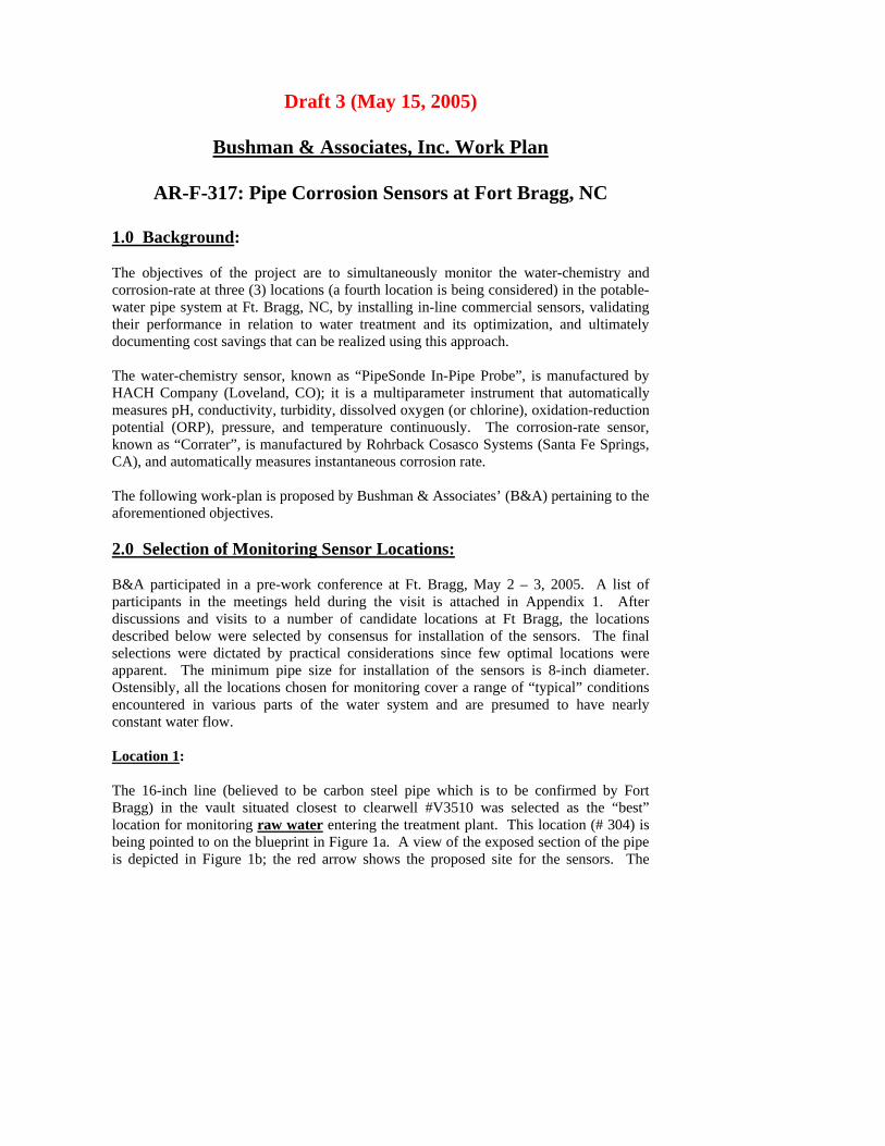
Draft 3 (May 15, 2005)
Bushman & Associates, Inc. Work Plan
AR-F-317: Pipe Corrosion Sensors at Fort Bragg, NC
1.0 Back
ground:
Th t are to simultaneously monitor the water-chemistry and co tions (a fourth location is being considered) in the potable-wathedo ThHA tically measu ction poknCA Thafo 2.0 Se
e objectives of the projecsion-rate at three (3) locarro
ter pipe system at Ft. Bragg, NC, by installing in-line commercial sensors, validating ir performance in relation to water treatment and its optimization, and ultimately cumenting cost savings that can be realized using this approach.
e water-chemistry sensor, known as “PipeSonde In-Pipe Probe”, is manufactured by CH Company (Loveland, CO); it is a multiparameter instrument that automa
res pH, conductivity, turbidity, dissolved oxygen (or chlorine), oxidation-redutential (ORP), pressure, and temperature continuously. The corrosion-rate sensor, own as “Corrater”, is manufactured by Rohrback Cosasco Systems (Santa Fe Springs, ), and automatically measures instantaneous corrosion rate.
e following work-plan is proposed by Bushman & Associates’ (B&A) pertaining to the rementioned objectives.
lection of Monitoring Sensor Locations: B&pa uring the visit is attached in Appendix 1. After dis d visits to a number of candidate locations at Ft Bragg, the locations des sors. The final sel al locations were apOsenco Lo
A participated in a pre-work conference at Ft. Bragg, May 2 – 3, 2005. A list of rticipants in the meetings held dcussions ancribed below were selected by consensus for installation of the sen
tions were dictated by practical considerations since few optimecparent. The minimum pipe size for installation of the sensors is 8-inch diameter. tensibly, all the locations chosen for monitoring cover a range of “typical” conditions countered in various parts of the water system and are presumed to have nearly nstant water flow.
cation 1:
e 16-inch line (believed to be carbon steel pipe which is to be confirmed by Fort agg) in the vault situated closest to clearwell #V3510 was selected as the “best” ation for monitoring raw water
ThBrloc entering the treatment plant. This location (# 304) is
ng pointed to on the bluepbei rint in Figure 1a. A view of the exposed section of the pipe is picted in Figure 1b; the red arrow shows the proposed site for the sensors. The de

distance between the wall and the flange is ~ 16 inches. The water pressure in this line is rep
ortedly ~ 140 psig.
1a. Proposed monitoring Location No. 1 pointed out on blueprint
Figure
Figure 1b. Pipe view at proposed monitoring Location No. 1

Location 2: Th inch line (believed to be carbon steel pipe which is to be confirmed by Fort Br#3
e 12-agg) in the vault situated near the high-lift pump house (containing valves #325 and 27) was selected as the “best” location for monitoring finished water entering the atment plant. The red arrow on the blueprint in Figure 2a indicates the proposed nitoring location. The exposed section of pipe for the sensor installation is indicated
the arrow in Figure 2b. The water pressure in this line is to be confirmed by Ft Bragg.
tremoby
2a. Proposed monitoring Location No. 2 arrowed on blueprint
Figure
gure 2b. Pipe view at proposed monitoring Location No. 2 Fi

Location 3: Th -inch line (believed to be ductile iron pipe which is to be confirmed by Fort Bragg) in mo
e 12the vault situated closest to the SCADA box at Tank Hill tank was selected as a “good” nitoring location representative of the water distribution system. This location is icted in Figure 3. The water pressure in this line is to be confirmed by Ft Bragg. dep
Figure 3. Proposed test location No. 3
tion 4
Potential Loca : CERL has proposed installing ld, which purportedly represents a high priori em. This ad onal activity is outside the present scope of work in the contract awarded to B&A. Fu not visited because the pipe is buried and no access was av y 2 – 3 visit. However, it was reported that the pipe can be un ered at a suitable location and a prefabricated vault installed to facilitate installation of sui 3.0
a fourth set of sensors at Simmons Fiety “problem” location in the water syst
diti rthermore, this location was ailable at the time of the Macovthe sensors. A contractor would have to be obtained to excavate the pipe and install a table vault to provide easy access for installation and operation of the two sensors.
Sensor Acquisition:
mediately after the work plan detailed in this document is approved, purchase orders ll be placed for three (3) PipeSonde water-chemistry sensors and three (3) Corrater rrosion-rate sensors with their respective manufacturers. The anticipated delivery
Imwicotim s are 4-6 weeks after ordering. The sensors will be delivered directly to the e

designated POC at Ft. Bragg where they will be inspected by B&A within 3 days after arr 4.0 Sensor Installation:
ival.
Th t time frame for installation of the sensors at Ft. Bragg is August, 2005. Ho ever, before the sensors can be installed, the pipes at the selected monitoring locintplueacinc
e targewations will need to be hot-tapped. Hot-tapping, which consists of providing access o the pipe interior without interruption of water flow, will be performed by a local mbing contractor that has provided this service previously; and paid for by CERL. At h monitoring location, it will be necessary to furnish and install two (2) pipe taps, luding saddles as required, incorporating a 2-inch ball valve for the water-chemistry ACH) sensor; and a 1-inch ball valve(H for the corrosion-rate (RCS) sensor. It is derstood that others will arrange for installation of these hot taps with saddles and ball lves prior to the scheduled installation of the probes. Location of these taps will have be coordinated with the sensor manufacturers and B&A to ensure correct size and entation for insertion and operation of the probes.
cording to the manufacturer, the water-chemistry sensor should be mounted at a clock sition between 700 and 200 with respect to the top of the pipe (which is 12 o’clock) to nimize risk of air-bubble entrapment under the sensing elem
unvato ori Acpomi ents’ protective shield. Th rrosion-rate sensor can be mounted at any angle. However, it is essential that for botim Thlearemdis ove) with oversight by the designated Ft. Bragg personnel. The corrosion sensor electrodes (carbon steel alloy UNS K03005; supplied by the sensor manufacturer) wimobepode 5.0
e coth types of sensors the sensing elements be completely immersed in the water at all es.
e first set of sensors will be installed with the designated Ft. Bragg personnel and at st the water-chemistry sensor manufacturer’s representative present on site. The aining sensor sets will be installed by B&A (through pre-furnished valves, as
cussed ab
ll be degreased and weighed individually to a precision of ± 0.1 mg before being unted on the corrosion-rate probes. The location of each electrode on the probe will
noted. Each probe will consist of 3 electrodes; i.e. 2 for performing the linear-larization resistance measurements (from which instantaneous, on-line corrosion rate is termined) and 1 freely-corroding, unpolarized, control “electrode”.
Sensor Wiring and Data Acquisition System:
e designated Ft. Bragg personnel will insure that a reliable 120V, 60 Hz, 1 Phase AC 24V supply is available for powering the sensors before they are installed. The total rrent requirements for both sensors at each location, including data acquisition,
Thor cumeasurement will be less than 1 amp. Appropriate metallic conduit and signal wiring are

also to be furnished by Ft. Bragg to protect the wiring between the sensors and the SC Th ensors will be connected to a Supervisory Control and Data Acquisition (SCADA) SywisystheSCMSwi Bouse checks. The co ion-rate senor uses a manufacturer-supplied solid-state “dummy cell” based on a Ra 6.0
ADA system; as well as for the power supply.
e sstem. There are two (2) SCADA systems at Ft. Bragg. The sensors will be interfaced th the SCADA #2 system that is presently used for monitoring pressures in the water tem. MSE is the on-site contractor (POC David Franklin) that set up and maintains SCADA #2 system. A contract will have to be awarded to MSE to perform the ADA interface work, data storage and visual display for use by Ft. Bragg personnel. E will also have to tranmit this data on a bi-weekly basis to B&A. B&A will work
th MSE to interface the sensors to the SCADA #2 system.
th sensors will be checked for calibration periodically. The water-chemistry sensor s several manufacturer-supplied “standard” solutions for calibration
rrosndles circuit, consisting of resistors and capacitors.
Data Acquisition and Analysis: Al eSonde) sensor are monitored l the parameters of the water-chemistry (Pipsim BUS via 2 wires, which would be interfaced to the SCADA system. The manufacturer recommends a data by the SCADA system at 15-minute intervals. For the corrosion-rate (Corrater) sensor, the output is 4-20 mAdatwawia Mdis DachmewiCE es will be ex ined, photographed, cleaned carefully to remove corrosion products, dried, and rewThtheelerepele
ultaneously and continuously. The output is MOD
which will be interfaced to the SCADA system; this manufacturer also recommends a collection every 15 minutes. The data collection frequencies can be modified if so rranted after review of the initial data obtained, e.g. during the first 2 weeks. MSE ll send the collected data to B&A on discs at regular intervals, e.g. every two weeks, as
icrosoft EXCEL spread sheets. B&A will analyze the data, graph it as necessary, and tribute it to designated personnel in monthly status reports.
ta analysis will consist of reviewing and comparing the data collected from the water-emistry sensors and corrosion-rate sensors to determine variations in the parameters asured and correlations between the data from the two sensors at each location. Data ll be compared to “grab” sample analysis, which will be conducted periodically by RL. At the conclusion of the testing, the corrosion sensor electrod
ameighed to a precision of ± 0.1 mg and the corrosion rate calculated from mass loss.
is will be compared with the integrated corrosion-rate versus time data obtained from sensor (linear polarization resistance) measurements made previously on the same ctrodes. Data from the third, freely-corroding, unpolarized, control “electrode” will resent an independent “calibration” check for the pair of corrosion-rate measuring ctrodes.
7.0 Reporting: B&A will provide electronic monthly progress reports in Microsoft Word, via e-mail. Thdaanthe Wifin uide Specification documenting the new sensing system, incGo Drapby ontact award for Government review. AnGo 8.0
e reports will document progress made during the preceding month, summary of any ta collected and analyzed, outline plans for the next reporting period, and recommend y changes in water treatment or other modifications to improve corrosion mitigation in water system.
thin 12 months of contract award, B&A will submit an electronic draft copy of the l Unified Facilities Ga
luding all information necessary to procure and interface pipe corrosion sensors for vernment review.
aft design, operation, and maintenance guidance suitable for incorporation into the plicable Technical Manuals, Technical and Engineering Instructions will be submitted
within 13 months of c B&A
electronic copy of the final report documenting all work, and incorporating vernment comments will be submitted by B&A within 15 months of contract award.
Meetings: B&A will attend a one-day interim project review meeting at CERL in Champaign, IL, aft all the sensors have been installed and at least 2 months of data have been collected. B& final wrap-up meeting at CERL in Champaign, IL, at the co
er
A will attend a one-dayf the project. nclusion o

Appendix 1
Personnel present at various meetings held du . Bragg, NC, May 2 –3, 2005. Contact phone numbers shown in parenthesis. Vi Vi James Bushman – President, Bushman & Associates (330-310-9099) “Bop” Phull – Corrosion Consultant, subcontractor Bushman & Associates (91 Jason Ly Ro es Engineer, FMD, DPW (910-396-4634) Te 0-396-1619) Ge Br da Audette – Water Resources Chief, DPW, FMD, (910-396-2022) Ke Gray – Area Engineer (910-396-1211) Ma Jud Da E Technology Applications (910-496-0038)
ring the visit to Ft
nce Hock – Project Area Leader, CERL (217-373-6753)
cki Van Blaricum – General Engineer/Project Manager, CERL (217-373-6771)
0-686-2516)
ons – Acting Chief, FMD, DPW (910-432-6010)
bert Mullen – Utiliti
d Kientz – COE Installation Support Manager, Savannah District (91
orge Whitby – Engineer, DPW (910-396-3702)
en
n
rcia Meekins – Resident Engineer (910-396-1211 ext 245)
i Hudson – Deputy Director, DPW (910-396-7202)
vid Franklin – Contractor SCADA maintenance, MS
Draft 1.0
Bushman & Associates, Inc. Communications Plan
AR-F-317: Pipe Corrosion Sensors at Fort Bragg, NC
1.0 Background: The objectives of the project are to simultaneously monitor the water-chemistry and corrosion-rate at four (4) locations in the potable-water pipe system at Ft. Bragg, NC, by installing in-line commercial sensors, validating their performance in relation to water treatment and its optimization, and ultimately documenting cost savings that can be realized using this approach. The water-chemistry sensor, known as “PipeSonde In-Pipe Probe”, is manufactured by HACH Company (Loveland, CO); it is a multiparameter instrument that automatically measures pH, conductivity, turbidity, dissolved oxygen (or chlorine), oxidation-reduction potential (ORP), pressure, and temperature continuously. The corrosion-rate sensor, known as “Corrater”, is manufactured by Rohrback Cosasco Systems (Santa Fe Springs, CA), and automatically measures instantaneous corrosion rate. The following is Bushman & Associates’ (B&A) communications plan for this project
Primary Client contact: Bushman & Associates, Inc. (B&A) primary contact will be with Ms. Vicki VanBlaricum [Office: (217) 373-6771], Project Manager (CERL). All contractual manners will be directed to her for handling. At Ft. Bragg, our primary contact will be ???? plus office and cell phone numbers. All communications dealing with scheduling and work activities will be routed through her and/or her designated Plant Managers. A monthly activities report will be prepared and sent to Ms. Vicki VanBlaricum at the first of each month until the project is completed, with a copy being sent to ??????. All communications dealing with this project from interested parties outside of B&A should be directed to the Primary contractor contact:
James B. Bushman, Project Administrator and Officer for B&A PO Box 425 Medina, OH 44258 Shipping Address: 6395 Kennard Road

Medina, OH 44256
Phone Office: 330-769-3694 Phone Cell: 330-310-9099 Fax: 330-769-2197 Email: [email protected]
Alternate contact:
Dr. Bopinder S. Phull, Project Manager and Corrosion Consultant (sub-contractor to B&A) 308 Humphrey Drive Wilmington, NC 28411
Phone Office: (910) 686-2516 Phone Cell: (910) 352-9030 Fax: (910) 686-2516 Email: [email protected]

Draft 1
Bushman & Associates Data Collection Plan
AR-F-317: Pipe Corrosion Sensors at Fort Bragg, NC
1.0 Background: The objectives of the project are to simultaneously monitor the water-chemistry and corrosion-rate at four (4) locations in the potable-water pipe system at Ft. Bragg, NC, by installing in-line commercial sensors, validating their performance in relation to water treatment and its optimization, and ultimately documenting cost savings that can be realized using this approach. The water-chemistry sensor, known as “PipeSonde In-Pipe Probe”, is manufactured by HACH Company (Loveland, CO); it is a multiparameter instrument that automatically measures pH, conductivity, turbidity, dissolved oxygen (or chlorine), oxidation-reduction potential (ORP), pressure, and temperature continuously. The corrosion-rate sensor, known as “Corrater”, is manufactured by Rohrback Cosasco Systems (Santa Fe Springs, CA), and automatically measures instantaneous corrosion rate. The following data collection plan is proposed by Bushman & Associates (B&A) for this project.
2.0 Data Collection The Supervisory Control And Advisory Data Acquisition (SCADA) system at Ft. Bragg will be used for collecting the raw data from three (3) water-chemistry and three (3) corrosion-rate sensors. This system was set up and is maintained by a contractor, MSE Technology Applications (POC David Franklin). MSE will interface the outputs from the sensors to the SCADA system. Each sensor will have a 2-wire output. The water-chemistry sensor output will be MODBUS; and the corrosion-rate sensor output will be 4-20 mA. Both sensors have real-time, continuous outputs. Manufacturers of both sensors have suggested a data collection frequency of once every 15 minutes by the SCADA system. After review of initial data (e.g. first week) by all interested parties, this frequency of data collection can be changed if necessary. 3.0 Data Transmission The data collected by the SCADA system will be downloaded to a disc in Microsoft EXCEL spreadsheet format and transmitted to B&A every 2 weeks by MSE. B&A will review the data, graph it as necessary and transmit it to the client, CERL (POC Vicki Van Blaricum), in monthly status reports. As agreed, the data will be shared with the

designated Ft. Bragg personnel as well as the sensor manufacturers for review and comment.

ERDC/CERL TR-07-21 E1
Appendix E: Corrosion and Data Interpretation Primer

Corrosion Primer by B&A
Corrosion Rate Measurement
Basics:
Aqueous corrosion is an electrochemical process, which involves charge transfer at
anodic and cathodic areas or sites. For example, for carbon steel and cast iron, the
following oxidation (metal loss or corrosion) reaction occurs at anodic areas by
loss of electrons:
Fe - 2e- Fe
2+
The electrons flow in the metal to cathodic areas where they are consumed by
some cathodic reaction(s):
For example, in deoxygenated acidic environments, the principal cathodic reaction
is hydrogen evolution:
2H+ + 2e
- H2
In aerated, neutral-pH environments (e.g. potable waters), the principal cathodic
reaction is reduction of dissolved oxygen to hydroxyl ions:
½ O2 + H2O + 2e- 2OH
-
The by-products of the anodic and cathodic reaction combine to precipitate the
familiar hydrated iron oxide or red rust.
Fe2+
+ 2OH- Fe(OH)2 + O2 Fe(OH)3
Thus, in neutral-pH environments, the corrosion rate of carbon steel is often
controlled by the dissolved oxygen concentration and its transport to the cathodic
areas. In systems open to the atmosphere, the dissolved oxygen content varies
inversely with temperature. Thus, transport of oxygen to the metal surface is
influenced by temperature, flow velocity and presence of any corrosion products or
other deposits, and various other factors.

Measurement:
Weight loss is a common method for determining corrosion rates. Replicate test
specimens are weighed, exposed to the environment of interest for a certain period,
cleaned to remove corrosion products and then re-weighed. If the corrosion
morphology is uniform or general in nature, the weight loss, specimen exposure
area, exposure time, and material density are used to compute a corrosion rate –
which is typically reported as material “thinning” or thickness loss in mils per
year (mpy; where 1 mil = 0.001 inch); or other customary units (e.g. micrometers
per year - µm/yr). The weight loss method indicates the average corrosion rate
over the exposure period.
The weight loss method does not provide any information on instantaneous
corrosion rate changes, e.g. due to variations in flow, temperature, oxidants or
inhibitor additions, etc. An alternative technique known as the Linear Polarization
Resistance (LPR) method is more appropriate for monitoring instantaneous
corrosion rates and lends itself ideally for on-line measurements. In the LPR
method, two, nominally identical electrodes of the test material are subjected to a
small DC voltage perturbation, e.g. ±10 mV with respect to each other. LPR is
computed from the ratio of this voltage to the current flow between the two
electrodes, normalized for surface area and corrected for solution resistivity. LPR
is inversely proportional to corrosion rate.
The Electrical Resistance (ER) technique is another method for determining
corrosion rate in which changes in the electrical resistance of a sensing element are
monitored (using a Kelvin-Wheatstone bridge instrument) as a function of time.
However, compared to the LPR method, the response time of ER method is not
instantaneous.
Commercial LPR Instrumentation:
The CORRATER is a commercial instrument that has been widely used by many
industries over the past 50+ years. It is covered by ASTM Standard G-96-2001:
Standard Guide for On-Line Monitoring of Corrosion in Plant Equipment
(Electrical and Electrochemical Methods). Instantaneous corrosion rates are
indicated in mpy for “standardarized” electrodes made from the material of
interest. Bare test electrodes are mounted on the front end of a probe that is
exposed to the test environment. The probe can be either be fixed type or
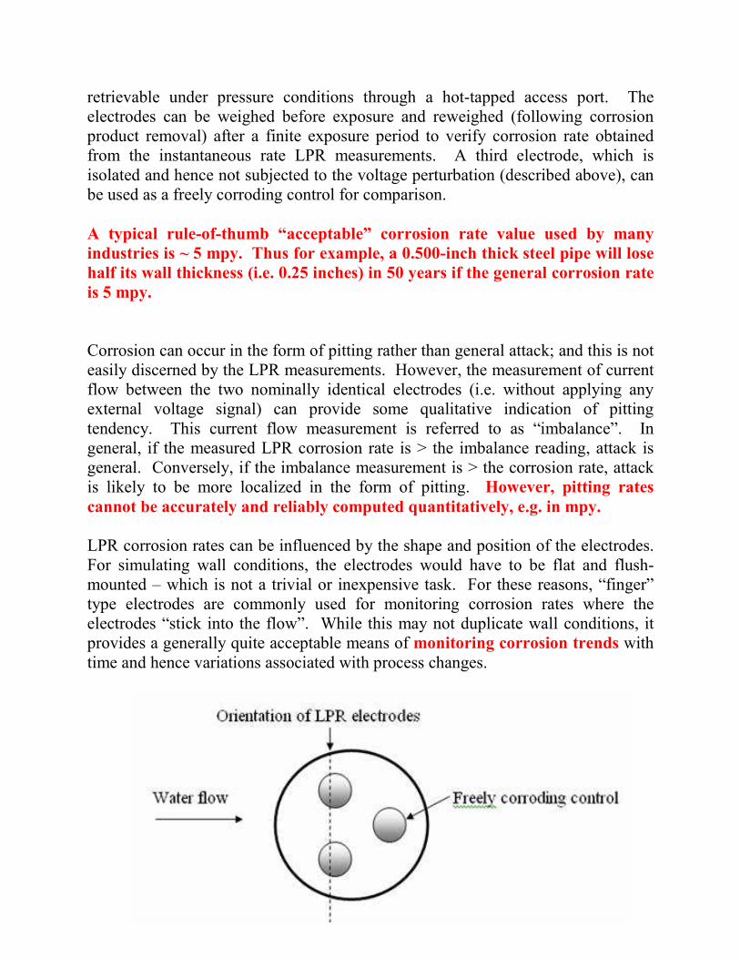
retrievable under pressure conditions through a hot-tapped access port. The
electrodes can be weighed before exposure and reweighed (following corrosion
product removal) after a finite exposure period to verify corrosion rate obtained
from the instantaneous rate LPR measurements. A third electrode, which is
isolated and hence not subjected to the voltage perturbation (described above), can
be used as a freely corroding control for comparison.
A typical rule-of-thumb “acceptable” corrosion rate value used by many
industries is ~ 5 mpy. Thus for example, a 0.500-inch thick steel pipe will lose
half its wall thickness (i.e. 0.25 inches) in 50 years if the general corrosion rate
is 5 mpy.
Corrosion can occur in the form of pitting rather than general attack; and this is not
easily discerned by the LPR measurements. However, the measurement of current
flow between the two nominally identical electrodes (i.e. without applying any
external voltage signal) can provide some qualitative indication of pitting
tendency. This current flow measurement is referred to as “imbalance”. In
general, if the measured LPR corrosion rate is > the imbalance reading, attack is
general. Conversely, if the imbalance measurement is > the corrosion rate, attack
is likely to be more localized in the form of pitting. However, pitting rates
cannot be accurately and reliably computed quantitatively, e.g. in mpy.
LPR corrosion rates can be influenced by the shape and position of the electrodes.
For simulating wall conditions, the electrodes would have to be flat and flush-
mounted – which is not a trivial or inexpensive task. For these reasons, “finger”
type electrodes are commonly used for monitoring corrosion rates where the
electrodes “stick into the flow”. While this may not duplicate wall conditions, it
provides a generally quite acceptable means of monitoring corrosion trends with
time and hence variations associated with process changes.

Water-Chemistry Primer by B&A
Water Chemistry Measurements (HACH PipeSonde Probe)
Parameter Units Description Typical Range
pH - Measures hydrogen ion activity, [H+]; measurement affected by
temperature, hence pH meters include temp compensation.
Corrosion rates of carbon steels and unalloyed cast irons in
potable waters are relatively insensitive to pH changes in the
near-neutral (6 - 9) range. Dissolved oxygen, CO2, temperature
and flow rate have greater effects on corrosion in this pH range.
pH influences formation of scale (e.g. CaCO3), which may be
protective.
6.5 – 8.5
ORP millivolts (mV) Oxidation Reduction Potential; also known as Redox
potential. Measure of water system’s ability to either
release electrons (oxidation) or gain electrons
(reduction) in chemical reactions. ORP generally
measured as potential of a Pt electrode vs. a reference
electrode and converted to standard hydrogen electrode
(SHE) scale.
Redox reactions control behavior of many chemical constituents.
Reactivity and solubility of critical elements in living matter
Theoretically –2000 to
+2000 mV
More typically 150 –
400 max.
> 400 can be harmful to
aquatic life;
>700 for disinfecting
water in swimming
pools.

strongly influenced by redox reaction conditions. ORP also
indicative of aerobic conditions (higher +ve values) and
anaerobic conditions (-ve values), which is also related to
bacterial activity. ORP can be used to indicate effectiveness of
treatment (e.g. chlorination) to “sanitize” water.
Very high ORP values
can also lead to
accelerated corrosion.
Conductivity micro-Siemens
per centimeter,
(µS/cm);
Often abbreviated
as µS
Measures ability of water to conduct electricity via ions; hence
indication of purity pertaining to dissolved solids.
Total dissolved solids (TDS) in mg/L ≈ 0.5 x conductivity
(µS/cm). Conductivity increases with temperature. In general,
corrosion rate increases with conductivity but other factors such
as dissolved oxygen, temperature, flow rate dominate.
900 max.
Potable waters
much lower,
typically < 100 µS
ditto
milli-Siemens
per centimeter,
(mS/cm)
1 mS = 1000 µS 0.9 max.
Salinity
Parts per
Thousand (ppt)
≈ 0.5 x conductivity (µS/cm) ÷ 1000; usually pertains to chloride-
dominant dissolved salts. Corrosion generally increases with
increasing chloride content, but other factors such as dissolved
oxygen, temperature, flow rate dominate.
e.g. seawater is ~
35 ppt; potable
waters much lower
Total
Dissolved
Solids (TDS)
Milligrams per
liter (mg/L)
Total sum of concentrations of all dissolved ions.
No simple/general correlation between TDS and corrosion
because some ions can be corrosive (e.g. chloride) while others,
e.g. calcium can contribute to protective scales.
500 max.
(250 max chloride;
250 max sulfate)

Dissolved
Oxygen (DO)
Milligrams per
liter (mg/L)
In open systems, DO varies inversely with temperature and
directly with barometric pressure. DO plays very significant role
in corrosion of carbon steels and passivation of stainless steels.
Corrosion of carbon steels and unalloyed cast irons increases with
DO concentration. Higher temperatures increase corrosion rate
although DO content may be lower. Flow rate also increases
corrosion by enhancing DO diffusion to the metal surface.
4 – 14
ditto Percent saturation
(%)
60 - 110
Turbidity
NTU
Measures of the cloudiness of water. Used to indicate water
quality and filtration effectiveness (e.g., whether disease-causing
organisms are present). Higher turbidity levels are often
associated with higher levels of disease-causing microorganisms
such as viruses, parasites and some bacteria. May indicate
sloughing/scouring of corrosion products, red-water.
No simple correlation between turbidity and corrosion.
5 max.
1 max for filtered
systems
Temperature
0C ,
0F,
0K, etc
In the absence of scale formation, corrosion rate increases with
temperature due to enhanced diffusion of DO (although DO
content decreases with temperature). Scale formation (e.g.
CaCO3 more favorable with increasing temperature.
Pressure
psi, bar, kPa, etc
Higher pressures can increase concentration of dissolved gases
(e.g. O2, CO2) and hence corrosion; no simple/general correlation
between corrosion and hydraulic pressure.

ERDC/CERL TR-07-21 F1
Appendix F: Updated Return on Investment (ROI) Projection
Method
OMB Circular A94, Appendix E is used for this updated return on invest-ment (ROI) projection.
Updated corrosion reduction rate
The ROI estimate that appeared in the project PMP prepared in 2004 (Appendix A) estimated that the corrosion rate would be reduced by 20% due to the application of proper water treatment. This was based on a 2001 report published by NACE International and the Federal Highway Administration.
Actual corrosion rates (summarized in Table F1) have been measured dur-ing this project.
Table F1. Summary of Actual Corrosion Rates Measured.
Location Is the water treated?
What the data represents General Corrosion Rate (mils/yr)
Water treatment plant (WTP) raw wa-ter inlet
No Expected corrosion rate for pipes exposed to untreated water
5.7
WTP finished water Yes Expected corrosion rate for pipes near the WTP
0.3
Simmons Army Air-field
Yes Expected corrosion rate for pipes at the most distant points of the water distribu-tion system (farthest from the WTP)
2.7
Tank Hill Yes Expected corrosion rate for pipes at an average distance away from the WTP.
4.7
This data indicates that the water treatment program at Fort Bragg is al-ready quite good. It is interesting to note, however, that the corrosion rate at the distant location (2.7 mils/yr) is significantly (42%) lower than the corrosion rate at the average location (4.7 mils/yr). Since the distant loca-tion usually represents the worst case conditions, it is reasonable to as-

ERDC/CERL TR-07-21 F2
sume that 2.7 mils/yr is attainable for the average location as well. This assumption will be used in the revised ROI projection.
Sensor maintenance and replacement cost
This project revealed the need for the pipe sensors to be regularly cleaned, maintained, and calibrated. As explained in Chapter 5, the sensors at Fort Bragg require quarterly maintenance by the manufacturer at a total cost of $12,000.
Assumptions for revised ROI calculation
Alternative 1: Baseline
A study completed at Fort Bragg in 2002 (“U. S. Army Corps of Engineers Government ‘Should-Cost’ Model for Privatization of Water-Wastewater Utility System”) identified annual water system operation and mainte-nance costs of approximately $2.6 million. This study also identified an-nual capital improvement costs of approximately $1.5 million that are needed in order to ensure that the system continues to provide adequate quantities of safe, high quality drinking water.
This capital improvement figure is used as an annual baseline cost in the ROI spreadsheet.
Alternative 2: Sensors installed
Data collected during this project has shown that Fort Bragg’s water treatment is already quite good. However, it is assumed that the corrosion rate of 2.7 mils/yr measured at the location farthest from the treatment plant (typically the worst case condition) should be attainable at all loca-tions, including the average location where the measured rate was 4.7 mils/yr. This is a reduction of 42%. It is also assumed that the average lo-cation represents 1/3 of the water distribution system, and that it is there-fore responsible for generating 1/3 of the capital costs ($500,000) and 1/3 of the operation/maintenance costs ($866,667). A 42% reduction in those costs amounts to an annual $210,000 reduction in capital costs and an annual $364,000 reduction in operation/maintenance costs.
Maintenance of the sensors costs $12,000 annually, and we assume that they will need to be replaced every 10 years at a cost of $80,000 for the 4 sets. Note that the pipe sensor is a diagnostic tool and does not prevent

ERDC/CERL TR-07-21 F3
corrosion by itself, thus time must be allowed for corrosion prevention measures to be designed and implemented once the sensor has pinpointed the problems. It is therefore conservatively assumed that the cost reduc-tions will begin to occur in Year 4 and will continue throughout the analy-sis period.
Comparing the two alternatives, the potential return-on-investment for Alternative 2 is projected to be 21.63.
250,000
21.63 Percent 2163%
45,469,400 50,875,670 5,406,270
A B C D E F G HFuture Year
Baseline Costs Baseline Benefits/Savings
New System Costs
New System Benefits/Savings
Present Value of Costs
Present Value of Savings
Total Present Value
1 4,100,000 4,112,000 3,843,075 3,831,860 -11,2152 4,100,000 4,112,000 3,591,421 3,580,940 -10,4813 4,100,000 4,112,000 3,356,626 3,346,830 -9,7964 4,100,000 3,538,000 2,699,140 3,127,890 428,7505 4,100,000 3,538,000 2,522,594 2,923,300 400,7066 4,100,000 3,538,000 2,357,369 2,731,830 374,4617 4,100,000 3,538,000 2,203,113 2,553,070 349,9578 4,100,000 3,538,000 2,059,116 2,386,200 327,0849 4,100,000 3,538,000 1,924,318 2,229,990 305,672
10 4,100,000 3,606,000 1,832,930 2,084,030 251,10011 4,100,000 3,538,000 1,680,904 1,947,910 267,00612 4,100,000 3,538,000 1,570,872 1,820,400 249,52813 4,100,000 3,538,000 1,468,270 1,701,500 233,23014 4,100,000 3,538,000 1,372,036 1,589,980 217,94415 4,100,000 3,538,000 1,282,171 1,485,840 203,66916 4,100,000 3,538,000 1,198,321 1,388,670 190,34917 4,100,000 3,538,000 1,120,131 1,298,060 177,92918 4,100,000 3,538,000 1,046,894 1,213,190 166,29619 4,100,000 3,538,000 978,257 1,133,650 155,39320 4,100,000 3,606,000 931,790 1,059,440 127,65021 4,100,000 3,538,000 854,427 990,150 135,72322 4,100,000 3,538,000 798,527 925,370 126,84323 4,100,000 3,538,000 746,164 864,690 118,52624 4,100,000 3,538,000 697,340 808,110 110,77025 4,100,000 3,538,000 651,700 755,220 103,52026 4,100,000 3,538,000 609,244 706,020 96,77627 4,100,000 3,538,000 569,264 659,690 90,42628 4,100,000 3,538,000 532,115 616,640 84,52529 4,100,000 3,538,000 497,443 576,460 79,01730 4,100,000 3,606,000 473,828 538,740 64,912
Return on Investment Calculation
Net Present Value of Costs and Benefits/Savings
Return on Investment Ratio
Investment Required

ERDC/CERL TR-07-21 F4
Year
MaintenanceCapital Improvement Total
Cost Avoidance Maintenance
Capital Improvement Total
1 2,600,000 1,500,000 4,100,000 2,612,000 1,500,000 4,112,0002 2,600,000 1,500,000 4,100,000 2,612,000 1,500,000 4,112,0003 2,600,000 1,500,000 4,100,000 2,612,000 1,500,000 4,112,0004 2,600,000 1,500,000 4,100,000 2,248,000 1,290,000 3,538,0005 2,600,000 1,500,000 4,100,000 2,248,000 1,290,000 3,538,0006 2,600,000 1,500,000 4,100,000 2,248,000 1,290,000 3,538,0007 2,600,000 1,500,000 4,100,000 2,248,000 1,290,000 3,538,0008 2,600,000 1,500,000 4,100,000 2,248,000 1,290,000 3,538,0009 2,600,000 1,500,000 4,100,000 2,248,000 1,290,000 3,538,000
10 2,600,000 1,500,000 4,100,000 2,316,000 1,290,000 3,606,00011 2,600,000 1,500,000 4,100,000 2,248,000 1,290,000 3,538,00012 2,600,000 1,500,000 4,100,000 2,248,000 1,290,000 3,538,00013 2,600,000 1,500,000 4,100,000 2,248,000 1,290,000 3,538,00014 2,600,000 1,500,000 4,100,000 2,248,000 1,290,000 3,538,00015 2,600,000 1,500,000 4,100,000 2,248,000 1,290,000 3,538,00016 2,600,000 1,500,000 4,100,000 2,248,000 1,290,000 3,538,00017 2,600,000 1,500,000 4,100,000 2,248,000 1,290,000 3,538,00018 2,600,000 1,500,000 4,100,000 2,248,000 1,290,000 3,538,00019 2,600,000 1,500,000 4,100,000 2,248,000 1,290,000 3,538,00020 2,600,000 1,500,000 4,100,000 2,316,000 1,290,000 3,606,00021 2,600,000 1,500,000 4,100,000 2,248,000 1,290,000 3,538,00022 2,600,000 1,500,000 4,100,000 2,248,000 1,290,000 3,538,00023 2,600,000 1,500,000 4,100,000 2,248,000 1,290,000 3,538,00024 2,600,000 1,500,000 4,100,000 2,248,000 1,290,000 3,538,00025 2,600,000 1,500,000 4,100,000 2,248,000 1,290,000 3,538,00026 2,600,000 1,500,000 4,100,000 2,248,000 1,290,000 3,538,00027 2,600,000 1,500,000 4,100,000 2,248,000 1,290,000 3,538,00028 2,600,000 1,500,000 4,100,000 2,248,000 1,290,000 3,538,00029 2,600,000 1,500,000 4,100,000 2,248,000 1,290,000 3,538,00030 2,600,000 1,500,000 4,100,000 2,316,000 1,290,000 3,606,000
O&M CostsNew System CostsOld System Costs

REPORT DOCUMENTATION PAGE Form Approved
OMB No. 0704-0188 Public reporting burden for this collection of information is estimated to average 1 hour per response, including the time for reviewing instructions, searching existing data sources, gathering and maintaining the data needed, and completing and reviewing this collection of information. Send comments regarding this burden estimate or any other aspect of this collection of information, including suggestions for reducing this burden to Department of Defense, Washington Headquarters Services, Directorate for Information Operations and Reports (0704-0188), 1215 Jefferson Davis Highway, Suite 1204, Arlington, VA 22202-4302. Respondents should be aware that notwithstanding any other provision of law, no person shall be subject to any penalty for failing to comply with a collection of information if it does not display a currently valid OMB control number. PLEASE DO NOT RETURN YOUR FORM TO THE ABOVE ADDRESS.
1. REPORT DATE (DD-MM-YYYY) June 2007
2. REPORT TYPE Final
3. DATES COVERED (From - To)
5a. CONTRACT NUMBER
5b. GRANT NUMBER
4. TITLE AND SUBTITLE
Demonstration of Pipe Corrosion Sensors at Fort Bragg, NC: Final Report on Project AR-F-317 for FY05
5c. PROGRAM ELEMENT NUMBER
5d. PROJECT NUMBER
5e. TASK NUMBER MIPR5CCERB1011, MIPR5CROBB1012
6. AUTHOR(S) Vicki L. Van Blaricum, Vincent F. Hock, James Bushman, Bopinder Phull
5f. WORK UNIT NUMBER
7. PERFORMING ORGANIZATION NAME(S) AND ADDRESS(ES) U.S. Army Engineer Research and Development Center Construction Engineering Research Laboratory P.O. Box 9005 Champaign, IL 61826-9005
8. PERFORMING ORGANIZATION REPORT NUMBER
ERDC/CERL TR-07-21
10. SPONSOR/MONITOR’S ACRONYM(S)
9. SPONSORING / MONITORING AGENCY NAME(S) AND ADDRESS(ES)
U.S. Army Installation Management Command Engineering Office, Directorate of Public Works (IMPW-E) 2511 Jefferson Davis Hwy. Arlington, VA 22202
11. SPONSOR/MONITOR’S REPORT NUMBER(S)
OSD CPC AR-F-317 12. DISTRIBUTION / AVAILABILITY STATEMENT
Approved for public release; distribution is unlimited.
13. SUPPLEMENTARY NOTES
14. ABSTRACT This Office of the Secretary of Defense Corrosion Prevention and Control Program project demonstrated the use of sensors that are permanently installed in the potable water distribution system to monitor water chemistry/corrosivity and corrosion rates. One water chemistry sensor and one corrosion-rate sensor were installed at four locations in the potable water distribution system at Fort Bragg, NC, and were interfaced with the supervisory control and data acquisition (SCADA) system in place for the installation’s water and wastewater distribution systems. This report describes project objectives, equipment acquisition, setup, and system initialization. Pre-liminary observations of operation and lessons learned are discussed.
15. SUBJECT TERMS Fort Bragg, NC; corrosion prevention; remote sensors; potable water distribution systems; water chemistry; public works
16. SECURITY CLASSIFICATION OF: 17. LIMITATION OF ABSTRACT
18. NUMBER OF PAGES
19a. NAME OF RESPONSIBLE PERSON
a. REPORT
Unclassified
b. ABSTRACT
Unclassified
c. THIS PAGE
Unclassified 237 19b. TELEPHONE NUMBER (include area code)
Standard Form 298 (Rev. 8-98) Prescribed by ANSI Std. 239.18