Embed Size (px)
Citation preview

ERA-GLONASS Conformance andPerformance TestingApplication Note
Products:
● R&S®CMW500
● R&S®CMW-KA094
● R&S®CMW-KA095
● R&S®SMBV100A
● R&S®SMBV-K360
Emergency Road Assistance (ERA-GLONASS) is a service provided in the Russian Federation with thegoal of reducing response times for accidents or other emergencies on the roadways. This applicationnote briefly describes the technology behind ERA-GLONASS and presents conformance tests for ERA-GLONASS using the R&S®CMW500 RF tester and the R&S®SMBV100A vector signal generator. A Testsoftware for ERA-GLONASS makes it quick and easy to perform these tests with the GSM or WCDMAwireless communications standard. It also shows a test solution for GNSS performance tests for ERA-GLONASS using the R&S®SMBV100A vector signal generator and the option R&S®SMBV-K360 togetherwith CMWrun.
Note:
The eCall Conformance and Performance Testing is described in Application Note 1MA241.
Visit our homepage for the most recent version of this application note (www.rohde-schwarz.com/appnote/1MA251).
This document is complemented by software. The software may be updated even if the version of thedocument remains unchanged.
Appli
catio
n Note
ERA_GLONASS ─ 1MA251_3e (01/2018)
Bern
hard
Sch
ulz

Contents
2Application Note ERA_GLONASS ─ 1MA251_3e (01/2018)
Contents1 Introduction............................................................................................ 3
2 What is ERA-GLONASS ?......................................................................6
3 Conformance Testing of IVS...............................................................14
4 GNSS Performance Testing................................................................ 59
5 Appendix...............................................................................................64
6 Rohde & Schwarz.................................................................................71

Introduction
3Application Note ERA_GLONASS ─ 1MA251_3e (01/2018)
1 IntroductionERA-GLONASS is a service provided in the Russian Federation with the goal of reduc-ing response times for accidents or other emergencies on the roadways. The Russiangovernment has enacted a law requiring integrated ERA modules on all new automo-bile models. ERA is harmonized with the European eCall system. It uses the sameprincipals and protocols, but provides further features like a redundant channel (SMS)for MSD transfer and is designed for services like, e.g., fleet management, a toll roadsystem or digital tachographs.
Although ERA-GLONASS can not prevent accidents, when accidents do occur, a callis placed automatically (e.g. when the airbag deploys) to the emergency number 112.Essential information (including the vehicle's current location) is transmitted in a stan-dard data format. The in-vehicle system (IVS) collects the data and transmits it via aGSM or WCDMA voice call to the public safety answering point (PSAP).

Introduction
4Application Note ERA_GLONASS ─ 1MA251_3e (01/2018)
Figure 1-1: ERA-GLONASS system: In an emergency situation, the car makes a cellular (GSM orWCDMA) emergency call to emergency services. The car automatically transmitsessential data, including its location. After that, an emergency services operator canspeak directly with the vehicle's occupants, e.g. to request additional information.
Performance and Conformance Tests
The application note describes the principles behind ERA-GLONASS and explainsboth, tests of the GNSS performance and tests of the IVS conformance.
The GNSS performance tests are for evaluation of the GNSS receiver of the IVS withtests for parameters like GNSS receiver sensitivity or the position accuracy.
The IVS conformance tests are for evaluation of the whole IVS, such as the correcttransmission of the whole data (MSD) via mobile networks (GSM or WCDMA) includinga valid vehicle position.

Introduction
5Application Note ERA_GLONASS ─ 1MA251_3e (01/2018)
IVS Conformance Tests
This application note describes the conformance testing of the IVS using the test solu-tion offered by Rohde & Schwarz.
The provided PC software and the test solution make it easier for the user to concen-trate on the actual test tasks:● Simulation of the PSAP and control of the ERA-GLONASS emergency calls via
GSM or WCDMA● Measurement of times and decoding of the minimum set of data (MSD)● Display of the exchanged protocol messages● An in-depth understanding of the specifications for wireless communications and
GNSS is not necessary● Deep familiarity with the operation of the test instrument is likewise unnecessary● All relevant GSM or WCDMA cellular network parameters can be modified● This allows reproducible measurement results● A true emergency call using the emergency number 112 is possible
GNSS Performance Tests
This application note describes the GNSS performance testing of the IVS using the testsolution offered by Rohde & Schwarz.
The provided PC software (CMWrun) and the test solution make it easier for the userto concentrate on the actual test tasks:● The test suite controls the test equipment via SCPI and the IVS via vendor-specific
commands.● The test cases are performed fully automatic, without user interaction.● An in-depth understanding of the specifications for GNSS is not necessary● Deep familiarity with the operation of the test instrument is likewise unnecessary● All relevant GNSS parameters can be modified● This allows reproducible measurement results
The following abbreviations are used in this Application Note for Rohde & Schwarz testequipment:● The R&S®CMW500 radio communication tester is referred to as the CMW.● The R&S®SMBV100A vector signal generator is referred to as the SMBV.

What is ERA-GLONASS ?
6Application Note ERA_GLONASS ─ 1MA251_3e (01/2018)
2 What is ERA-GLONASS ?
2.1 ERA-GLONASS: System and Concepts
ERA-GLONASS is a service provided in the Russian Federation with the goal of reduc-ing response times for accidents or other emergencies on the roadways. The Russiangovernment has enacted a law requiring integrated ERA modules on all new automo-bile models. ERA is harmonized with the European eCall system. It uses the sameprincipals and protocols, but provides further features like a redundant channel (SMS)or additional data services.
Table 2-1: Features and differences ERA/eCall
Feature eCall ERA-GLONASS
Radio Access Networks GSM(2G) / UMTS(3G)(optional) GSM(2G) / UMTS(3G)
GNSS GPS GLONASS (mandatory), GPS
In-Band Modem yes yes ( same to pan-EuropeaneCall)
secondary (redundant) channel no SMS
MSD MSD MSD (like the MSD in eCall, butoptional additional fields)
additional (packet) data channel no yesfor location-based services like● fleet management● insurance telematics● toll collection● recovery of stolen vehicles● digital tachygraphy
Although ERA-GLONASS can not prevent accidents, when accidents do occur, a callis placed automatically (e.g. when the airbag deploys) to the emergency number 112.Essential information (including the vehicle's current location) is transmitted in a stan-dard data format. In addition to the automatic call, ERA can also be used to place a callmanually (e.g. in another type of emergency).
See Chapter 1, "Introduction", on page 3 for an overview.
An in-vehicle system (IVS) is integrated as a key element into every automobile (Fig-ure 2-1). The primary components of the IVS are a GNSS receiver (GLONASS, typi-cally in combination with GPS) to determine the current position and a cellular module(GSM and/or WCDMA) to permit transmission of the minimum set of data (MSD) via acellular network to a public safety answering point (PSAP). The data is transmittedover a voice channel on the cellular network because voice channels coverage is bet-ter, e.g in rural areas. Pure data channels are not available in every base station,depending on the configuration. However, because voice channels are used, the datamust be specifically adapted to the speech coder. This is done by means of a special-ized modulation in a so called in-band modem.
ERA-GLONASS: System and Concepts
What is ERA-GLONASS ?
7Application Note ERA_GLONASS ─ 1MA251_3e (01/2018)
Figure 2-1: Key components of ERA-GLONASS: The IVS prepares essential data and transmits it viathe voice channel over the air interface.
The public safety answering point (PSAP, e.g. police, fire, EMT) answers the call (andreceives the data) and initiates the appropriate response (e.g. dispatching an ambu-lance). The voice connection can then be used to request additional information.
The IVS transmits the data to the PSAP as standardized MSD.
Table 2-2: MSD data fields (version 2). The most critical data is the vehicle's location (blocks 7...11)
Block Name Necessity Description
1 Format version Mandatory MSD format version; set to 2 for the current format EN15722:2015
2 Message identifier Mandatory Session specific counter; starts at 1 and is incrementedwith every retransmission
3 Control Mandatory Conveys the following information:
Automatic or manual activation test call (TRUE/FALSE)
Test call (TRUE/FALSE)
Position can be trusted (TRUE/FALSE)
Vehicle class
4 Vehicle ID Mandatory VIN (vehicle identification number) according to ISO3779
5 Propulsion type (energystorage)
Mandatory Gasoline, diesel, hydrogen, electric, etc. (TRUE/FALSE)
6 Timestamp Mandatory Timestamp of incident event
7 Vehicle location Mandatory Last known vehicle position. Latitude and longitude (ISO6709) in milliarcseconds
8 Vehicle direction Mandatory Deviation from the direction to the magnetic north pole in 2degrees steps
9 Recent vehicle locationn-1
Optional Change in latitude and longitude compared to the lastMSD transmission
10 Recent vehicle locationn-2
Optional Change in latitude and longitude compared to the last butone MSD transmission
ERA-GLONASS: System and Concepts
What is ERA-GLONASS ?
8Application Note ERA_GLONASS ─ 1MA251_3e (01/2018)
11 No. of passengers Optional Number of occupants in the vehicle according to availableinformation.
12 Optional additional data Optional Optional information for the emergency rescue service(103 bytes, ASN.1 encoded); may also point to anaddress, where this information is located
In-Band modem: primary MSD transmission
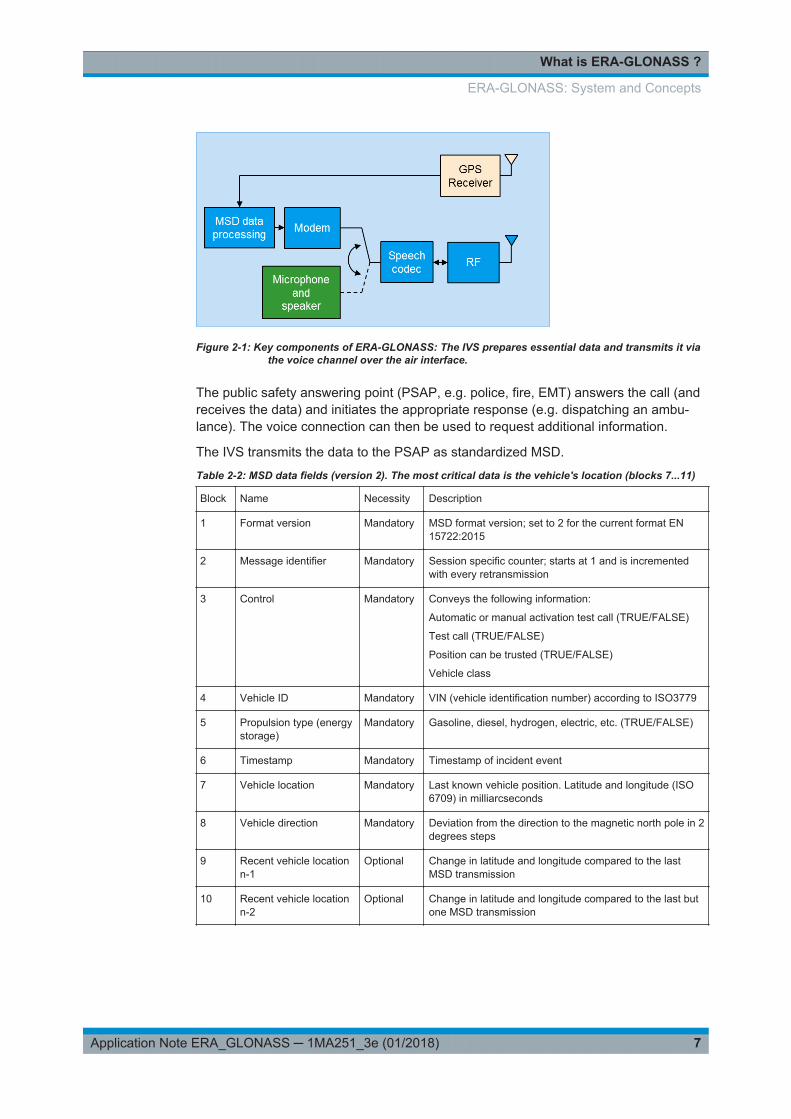
The MSD consists of 140 bytes and 28 CRC bits, making it a total of 1148 bits inlength. After the coding for the forward error correction, the MSD is 1380 bits in length.An MSD consists of a prefixed synchronization frame and three data parts. Betweenthe individual parts, the signal is muted (Figure 2-2).
Figure 2-2: The MSD consists of a sync frame and three individual MSD parts (uplink data parts). Inbetween the parts, the signal is muted. An excerpt from an example audio file (wav for-mat) is shown at the bottom of the figure.
The MSD data is bipolar pulse position modulated (BPPM). A basic pulse (pUL(n)) isoffset either in the positive or negative direction (Figure 2-3). In total, three bits arepacked into a symbol, and eight different symbols are available. There are two modes,fast and robust. In robust mode, the symbols are transmitted at double the spacingcompared to fast mode. This makes it easier for the receiver to recognize the symbolsin situations where the channel conditions are poor.
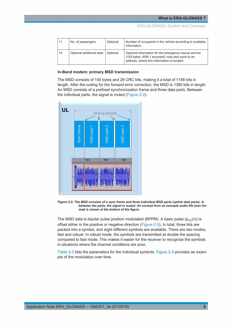
Table 2-3 lists the parameters for the individual symbols. Figure 2-4 provides an exam-ple of the modulation over time.
ERA-GLONASS: System and Concepts

What is ERA-GLONASS ?
9Application Note ERA_GLONASS ─ 1MA251_3e (01/2018)
Figure 2-3: The basic BPPM pulse (pUL (n)) (shown here in fast mode as an example).
Table 2-3: Symbol modulation mapping (according to [2]) wUL(n) = q (p(n) -> k)
Symbol Uplink waveform
(fast mode: n = 0,1,...,15)
Uplink waveform
(robust mode: n = 0,1,...,31))
d b sign q cyclic shift k sign q cyclic shift k
0 000 1 0 1 0
1 001 1 4 1 8
2 010 1 8 1 16
3 011 1 12 1 24
4 100 –1 12 –1 24
5 101 –1 8 –1 16
6 110 –1 4 –1 8
7 111 –1 0 –1 0
ERA-GLONASS: System and Concepts
What is ERA-GLONASS ?
10Application Note ERA_GLONASS ─ 1MA251_3e (01/2018)
Figure 2-4: Overview of the pulses in one frame. Robust mode is shown at the top and fast mode atthe bottom [2].
secondary channel: SMS
As a backup method, in ERA-GLONASS SMS can be used to transmit the MSD. Thisis the secondary possibility in order to increase the probability of the MSD reception.The SMS transmission can be requested by the PSAP, if the voice connection hasbeen established successfully but the correct MSD reception fails. It also can be usedby the IVS if the voice channel cannot be established successfully.
additional data channel
As a basic service, data channels can be used for additional location-based services(see Table 2-1). Here the packet data channel possibilities already provided by GSMlike (E)GPRS or WCDMA like HSPA(+) are used.
2.2 Sequences
The following figure uses a typical scenario to illustrate communications over the time.
Sequences

What is ERA-GLONASS ?
11Application Note ERA_GLONASS ─ 1MA251_3e (01/2018)
Figure 2-5: Typical ERA-GLONASS sequence. Transmission of the MSD is an iterative process. If thePSAP does not understand the MSD, it transmits NACK and the IVS resends the MSDwith a different redundancy version (RV0....7). If the MSD is received successfully, thePSAP sends an ACK.
Figure 2-6: The call sequence as seen in the audio file (IVS at the top, PSAP at the bottom).
1. When an emergency occurs, the IVS automatically sets up a connection (emer-gency call) to the PSAP over GSM or WCDMA ("Establish Call"). START mes-sages are then sent continuously (maximum of 5 times, "Initiation").
2. As soon as the PSAP receives the Call and has recognized the START signal, ittransmits the SEND-MSD command to the IVS.
Sequences

What is ERA-GLONASS ?
12Application Note ERA_GLONASS ─ 1MA251_3e (01/2018)
3. Once the IVS has successfully decoded the SEND-MSD ('Downlink Start') com-mand, it transmits one SYNC frame followed by the actual MSD with redundancyversion RV0 ("MSD").
4. (Only in Figure 2-6): In the example, the PSAP does not understand MSD RV0 andtherefore responds with a NACK ("MSD").
5. (Only in Figure 2-6 ): The IVS recognizes the NACK and resends the MSD withRV1 to the PSAP ("MSD").
6. The PSAP successfully decodes the MSD RV1 (CRC check), and transmits LL-ACK as feedback. The IVS stops transmitting the MSD.
7. The PSAP transmits AL-ACK, which indicates that the eCall is successfully com-pleted and the data in the MSD is understood. The connection then switches backto voice. A PSAP operator can now speak with the vehicle occupants, for example.Finally, the GSM or WCDMA connection is cleared down ("Release Call")
2.3 Standards
ERA-GLONASS is defined by a number of different standards by the Russian FederalAgency on Technical Regulating and Metrology (GOST) (Please note that this list isnot complete):
General● GOST 33465-2015: Global Navigation Satellite System. EMERGENCY
RESPONSE SYSTEM IN CASE OF ACCIDENTS. The data exchange protocol ofthe device/system of calling emergency services with the infrastructure of emer-gency response system in case of accidents.
● GOST 33464-2015: Global Navigation Satellite System. EMERGENCYRESPONSE SYSTEM IN CASE OF ACCIDENTS. The device/system of callingemergency services. General technical requirements.
Compliance Testing● GOST 33467-2015: Global Navigation Satellite System. EMERGENCY
RESPONSE SYSTEM IN CASE OF ACCIDENTS. Methods of functional testing ofthe device/system of calling emergency services and data transfer protocols.
● GOST 33468-2015: Global Navigation Satellite System. EMERGENCYRESPONSE SYSTEM IN CASE OF ACCIDENTS. Test methods of the device/system of calling emergency services for compliance with the requirements forloudspeaker communication quality in a vehicle cabin.
● GOST 33470-2015: Global Navigation Satellite System. EMERGENCYRESPONSE SYSTEM IN CASE OF ACCIDENTS. Test methods of wireless com-munication modules in the device/system of calling emergency services.
● GOST 33471-2015: Global Navigation Satellite System. EMERGENCYRESPONSE SYSTEM IN CASE OF ACCIDENTS. Test methods for navigationmodule of the device/system of calling emergency services.
Standards

What is ERA-GLONASS ?
13Application Note ERA_GLONASS ─ 1MA251_3e (01/2018)
Please note that the numbering of the standards differ in Russia and the Eurasian Cus-toms Union.
Table 2-4: Different Names of Standards
Eurasian Customs Union Russia
General
GOST 33465-2015 GOST R 54619-2011
GOST 33464-2015 GOST R 54620-2011
GOST R 54721-2011
GOST R 55524-2013
Compliance Testing
GOST 33467-2015 GOST R 55530-2013
GOST 33468-2015 GOST R 55531-2013
GOST 33470-2015 GOST R 55533-2013
GOST 33471-2015 GOST R 55534-2013:
ERA-GLONASS is harmonized with eCall, thus standards used by eCall also applyFigure 2-7 shows these standards.
Figure 2-7: Overview of the most important standards.
The solution from Rohde & Schwarz presented here fulfills all requirements from thesestandards. It ensures that the end-to-end conformance test complies with GOST33465-2015 [1] and the GNSS performance tests with GOST 33471-2015 [6], as dis-cussed in the next chapters.
Standards

Conformance Testing of IVS
14Application Note ERA_GLONASS ─ 1MA251_3e (01/2018)
3 Conformance Testing of IVS
3.1 Why test in the lab?
Testing of ERA-GLONASS devices is necessary at various levels:
● Module level (board)– R&D, design verification– Production– Maintenance
● Device level (IVS)– R&D, design verification– Coexistence– Conformance testing– Acceptance testing– Production– Repair / maintenance
● System level (car)– Radiated performance– Vehicle body specific– Coexistence– Desensitization– Outdoor, indoor
The solution presented here is intended for tests at the module level and at the devicelevel. This solution permits all basic parameters of the GSM or WCDMA network set-tings, such as channel or level, to be managed directly. As a result, measurements arefully reproducible. A true emergency call using the emergency number 112 in shieldedenvironment is additionally possible. The effects of uncontrolled settings, such as thosemade by network operators, is avoided.
3.2 Test Setup
The test solution presented here covers the conformance test for ERA-GLONASS inline with GOST 33465-2015 [1]. Figure 3-1 shows the simplified test setup without anexternal sound card, Figure 3-2with external sound card.
Select the wanted test setup in the PSAP settings (see Figure 3-6)
Test Setup
Conformance Testing of IVS
15Application Note ERA_GLONASS ─ 1MA251_3e (01/2018)
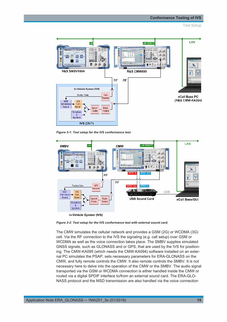
Figure 3-1: Test setup for the IVS conformance test.
Figure 3-2: Test setup for the IVS conformance test with external sound card.
The CMW simulates the cellular network and provides a GSM (2G) or WCDMA (3G)cell. Via the RF connection to the IVS the signaling (e.g. call setup) over GSM orWCDMA as well as the voice connection takes place. The SMBV supplies simulatedGNSS signals, such as GLONASS and or GPS, that are used by the IVS for position-ing. The CMW-KA095 (which needs the CMW-KA094) software installed on an exter-nal PC simulates the PSAP, sets necessary parameters for ERA-GLONASS on theCMW, and fully remote controls the CMW. It also remote controls the SMBV. It is notnecessary here to delve into the operation of the CMW or the SMBV. The audio signaltransported via the GSM or WCDMA connection is either handled inside the CMW orrouted via a digital SPDIF interface to/from an external sound card. The ERA-GLO-NASS protocol and the MSD transmission are also handled via the voice connection
Test Setup

Conformance Testing of IVS
16Application Note ERA_GLONASS ─ 1MA251_3e (01/2018)
between the CMW and the IVS. The end-to-end conformance test runs between thePSAP simulator installed on the external PC and the IVS under test.
3.2.1 CMW Radio Communication Tester
The CMW is the all-in-one test solution for radiocommunications applications such asmobile radio or wireless connectivity. It supports all essential standards, including:
● 2G– GSM, EGPRS, EGPRS2, EGDE Evolution and VAMOS
● 3G– W-CDMA with HSDPA, HSUPA and HSPA+
– TD-SCDMA
– CDMA2000 and 1xEV-DO Rev A/B● 4G
– LTE (FDD and TDD), LTE-A incl. MIMO● Wireless Connectivity
– Bluetooth
– WLAN
– WiMAX
The CMW tests all OSI layers, ranging from the physical layer to end-to-end tests,including both RF tests and protocol tests.
The additional packet data channels can be tested with the CMW standalone withoutthe ERA-GLONASS software KA095.
Test Setup

Conformance Testing of IVS
17Application Note ERA_GLONASS ─ 1MA251_3e (01/2018)
3.2.2 SMBV Vector Signal Generator
In its role as signal generator, the SMBV supports various wireless communicationsstandards as well as other radio standards. It serves as a specialist for GNSS signalsand generates the GNSS signals for ERA-GLONASS.
A brief overview of the GNSS characteristics:
● GPS, Glonass, Galileo, BeiDou, QZSS● Up to 24 satellites can be simulated● Automatic satellite handover for unlimited simulation time is supported● The sky view section displays the current position and state (active or inactive) of
the satellites.● Multipath scenarios such as observed in dense cities (LOS + echoes)● Moving scenarios simulate the motion of a receiver along a user-defined trajectory
such as observed in a moving car (waypoint formats supported such as KML,NMEA files)
● The map view section shows the current position of the receiver, which means thatthe receiver trajectory can be observed
Test Setup

Conformance Testing of IVS
18Application Note ERA_GLONASS ─ 1MA251_3e (01/2018)
Figure 3-3: Example for a satellite configuration in the SMBV.
Figure 3-4: The Sky View shows the distribution of the satellites above the local horizon
Test Setup

Conformance Testing of IVS
19Application Note ERA_GLONASS ─ 1MA251_3e (01/2018)
Needed GNSS options
Following options of the SMBV are needed for eCall / ERA-GLONASS:
Table 3-1: GNSS Scenarios
Scenario OptionSMBV
Configuration Satellites
GPS - City K44 static, selectable city fixed satellite constellation
GLONASS - City K94 static, selectable city fixed satellite constellation
GPS - Atlanta K65 static, Atlanta location fixed satellite constellation
GPS - Melbourne K65 static, Melbourne location fixed satellite constellation
GPS - Melbourne moving K65 moving, Melbourne loca-tion
fixed satellite constellation
GPS - Atlanta Individual Power K65 static, Atlanta location variable satellite constellation
GPS - Melbourne Individual Power K65 static, Melbourne location variable satellite constellation
GPS - Melbourne moving, Individual Power K65 moving, Melbourne loca-tion
variable satellite constellation
GPS - Santa Cruz Individual Power K65 static, Santa Cruz location variable satellite constellation
GPS - Santa Cruz moving, Individual Power K65 moving, Santa Cruz loca-tion
variable satellite constellation
GPS - Atlanta Individual Power (3GPP TS51.010.1V7.7.0)
K65 static, Atlanta location variable satellite constellation
GPS - Tokyo Individual Power K65 static, Tokyo location variable satellite constellation
GPS - Barcelona moving K65 moving, Barcelona loca-tion
fixed satellite constellation
The GPS City and GLONASS City scenarios both support following cities:
● New York● Sydney● Munich● Moscow● Tokyo● Seoul
Test Setup

Conformance Testing of IVS
20Application Note ERA_GLONASS ─ 1MA251_3e (01/2018)
3.2.3 KA095 PSAP Simulator Software (ERA-GLONASS Test Software)
The CMW-KA095 software runs on an external PC and serves as the PSAP simulator.It also remotely controls (e.g. via LAN) the CMW and the SMBV. The SW runs the end-to-end conformance test. The MSD is decoded and the measurement results are dis-played:
● PSAP simulation for ERA-GLONASS over GSM or WCDMA● MSD transmission time● Time since call establishment● Time since start trigger (from PSAP)● MSD decoding according to CEN EN 15722:2015 and GOST R 54620-2011 A1 for
every redundancy version and uplink data part● Optional recording of un-decoded signal from IVS● Details on PUSH and SYNC indications
– Timing– Count
● SMS protocol with more than 200 SMS commands based on GOST R 54619-2011● Optional: Fixed position GPS/GLONASS simulation / GPS moving scenario
3.3 The First ERA-GLONASS Measurement: Basic Opera-tion
The following sections describe the general process for setting up an ERA-GLONASS.The procedures guide you through the test system preparation and an ERA-GLONASSwith MSD transfer from the IVS to the simulated PSAP.
Use the test setup shown in Figure 3-2.
The IVS to be tested is connected via an RF cable to a CMW that simulates a GSM orWCDMA cell. Via this connection, the IVS establishes a GSM emergency call and
The First ERA-GLONASS Measurement: Basic Operation

Conformance Testing of IVS
21Application Note ERA_GLONASS ─ 1MA251_3e (01/2018)
transfers an MSD to the CMW. The GNSS signal is provided via an RF cable to theIVS.
The audio signal transported via the GSM or WCDMA connection is routed via a digitalSPDIF interface to/from an external sound card.
The ERA-GLONASS application base and GUI are installed on a PC. The applicationsimulates a PSAP, controls the CMW via the LAN and accesses the sound card via aUSB connection.
3.3.1 Preparing the Test Setup
The following steps prepare the test setup and start the ERA-GLONASS application.
1. Prepare the test setup shown in :
a) Connect the PC to the LAN.b) Connect the "LAN REMOTE" connector on the rear panel of the CMW to the
LAN.c) Connect the "LAN" connector on the rear panel of the SMBV to the LAN.d) Connect the GSM RF connector of the IVS to "RF 1 COM" on the front panel of
the CMW.e) Connect the GPS RF connector of the IVS to "RF" on the front panel of the
SMBV.f) (optional for use of external soundcard (CMW-Z94): Connect the rear panel of
the sound card to the rear panel of the CMW:
The cables are delivered together with the sound card (CMW-Z94).g) Connect the sound card via a USB cable to the PC.
2. Set up the PC. The required steps are described in detail in the CMW-KA095 UserManual, section "Preparing the Test System for Use".
The following list gives an overview:● Install the ERA-GLONASS application software.● Install the .NET Framework 4.0.● Install a VISA library with development support for .NET Framework 4.0.● Install the sound card driver and configure the sound card.● Configure the sound device settings of the PC.
The First ERA-GLONASS Measurement: Basic Operation

Conformance Testing of IVS
22Application Note ERA_GLONASS ─ 1MA251_3e (01/2018)
● Make the license CMW-KA095 (and for the CMW-KA094) available, for exam-ple by attaching a smart card with the license.
3.3.2 SIM Card (UICC)
The Subscriber Identity Modul (SIM-Card) allows mobile devices (UE) identificationand authentication in a mobile network. Typically the network providers hand out SIM-Cards to the endusers to allow access to the provider's mobile network. Whenswitched on, the UE searches for basestaions with certain codes (Mobile NetworkCode - MNC). With the registration the UE transmits the IMSI (International MobileSubscriber Identity), which is stored on the SIM card. Additionally, certain codes andalgorithm saved on the SIM-Card allow ciphering of signaling data and user data. E.g.in WCDMA, a certain authentication code is needed to register to the network and tosetup a connection successfully.
Rohde & Schwarz provides special SIM-Cards for testing UE's with the CMW. With theuse of these SIM-cards, the UE registers to the network provided by the CMW. Thusthe UE does not register to 'real' mobile networks.
3.3.3 Starting and Configuring the ERA-GLONASS Test Software (KA095)
The following steps start the eCall test software and adapt the settings to the testsetup.
The procedure explains the required steps, starting from the default settings. If youhave already modified settings, you may reset the settings to their default values bydeleting or renaming the following configuration file before starting the application:%APPDATA%\Rohde-Schwarz\CMW-KA09x_GUI\<version>\user.config. TheeCall test software consists of two parts:
1. Start the ERA-GLONASS test software base:"Windows Start" menu > "All Programs" > "R&S CMW-KA09x" > "KA09x Applica-tion Base"
A console window opens. A successful start is indicated as "Startup done!".
The First ERA-GLONASS Measurement: Basic Operation

Conformance Testing of IVS
23Application Note ERA_GLONASS ─ 1MA251_3e (01/2018)
2. Start the ERA-GLONASS test software GUI:"Windows Start" menu > "All Programs" > "R&S CMW-KA09x" > "KA09x Appl Soft-ware GUI"
The "CMW-KA09x GUI" window opens.
3. Connect the GUI to the base:"Base" menu > "Connect"After a successful connection, the GUI looks as follows.
The First ERA-GLONASS Measurement: Basic Operation

Conformance Testing of IVS
24Application Note ERA_GLONASS ─ 1MA251_3e (01/2018)
The status bar indicates the base state "Idle".
4. Select the CMW as RAN simulator:"Device Setup" menu > "RAN Simulator" > "CMW"
5. Select the SMBV as GNSS simulator:"Device Setup" menu > "GNSS Simulator" > "SMBV"
6. Display the CMW settings:"Device Setup" menu > "RAN Simulator" > "Edit configuration"
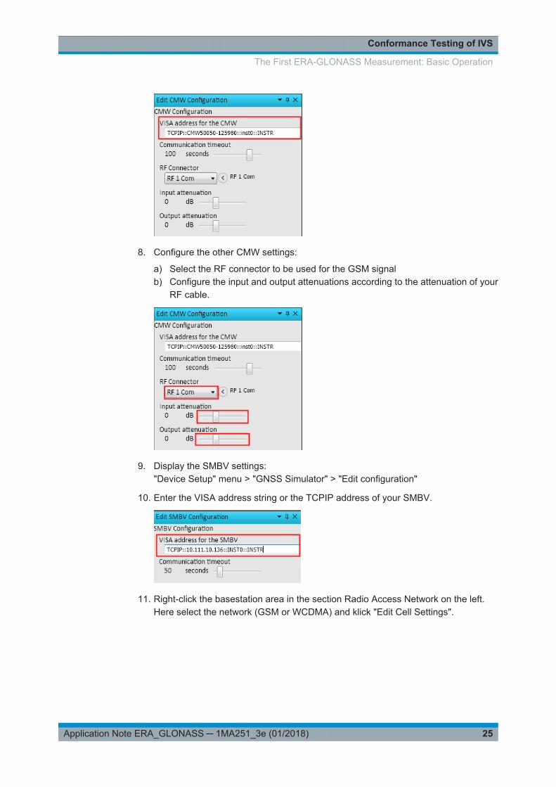
7. Enter the VISA address string or the TCPIP address of your CMW.
The First ERA-GLONASS Measurement: Basic Operation
Conformance Testing of IVS
25Application Note ERA_GLONASS ─ 1MA251_3e (01/2018)
8. Configure the other CMW settings:
a) Select the RF connector to be used for the GSM signalb) Configure the input and output attenuations according to the attenuation of your
RF cable.
9. Display the SMBV settings:"Device Setup" menu > "GNSS Simulator" > "Edit configuration"
10. Enter the VISA address string or the TCPIP address of your SMBV.
11. Right-click the basestation area in the section Radio Access Network on the left.Here select the network (GSM or WCDMA) and klick "Edit Cell Settings".
The First ERA-GLONASS Measurement: Basic Operation

Conformance Testing of IVS
26Application Note ERA_GLONASS ─ 1MA251_3e (01/2018)
The cell settings (GSM or WCDMA) are displayed on the right. Please note that inWCDMA the Connection Configuration must be set to "Voice" always.
The First ERA-GLONASS Measurement: Basic Operation

Conformance Testing of IVS
27Application Note ERA_GLONASS ─ 1MA251_3e (01/2018)
12. Check that the cell settings are compatible to your IVS.If required, modify the settings, for example the band, the channel number and thepower levels.Special settings for SIM-Cards can be handled via "Use custom network securitysettings"
The First ERA-GLONASS Measurement: Basic Operation

Conformance Testing of IVS
28Application Note ERA_GLONASS ─ 1MA251_3e (01/2018)
Figure 3-5: Important settings for SIM-Cards. Left: WCDMA; right: GSM
If you subsequently modify settings after the initial configuration, click "UpdateConfiguration" at the bottom to apply the changes.
13. Right-click the PSAP area in the section Radio Access Network on the left. Hereselect the PSAP simulation "ERA-GLONASS"
14. To use GLONASS, right-click SMx area on the left. Here select the "GLONASS -City Scenario"
The First ERA-GLONASS Measurement: Basic Operation
Conformance Testing of IVS
29Application Note ERA_GLONASS ─ 1MA251_3e (01/2018)
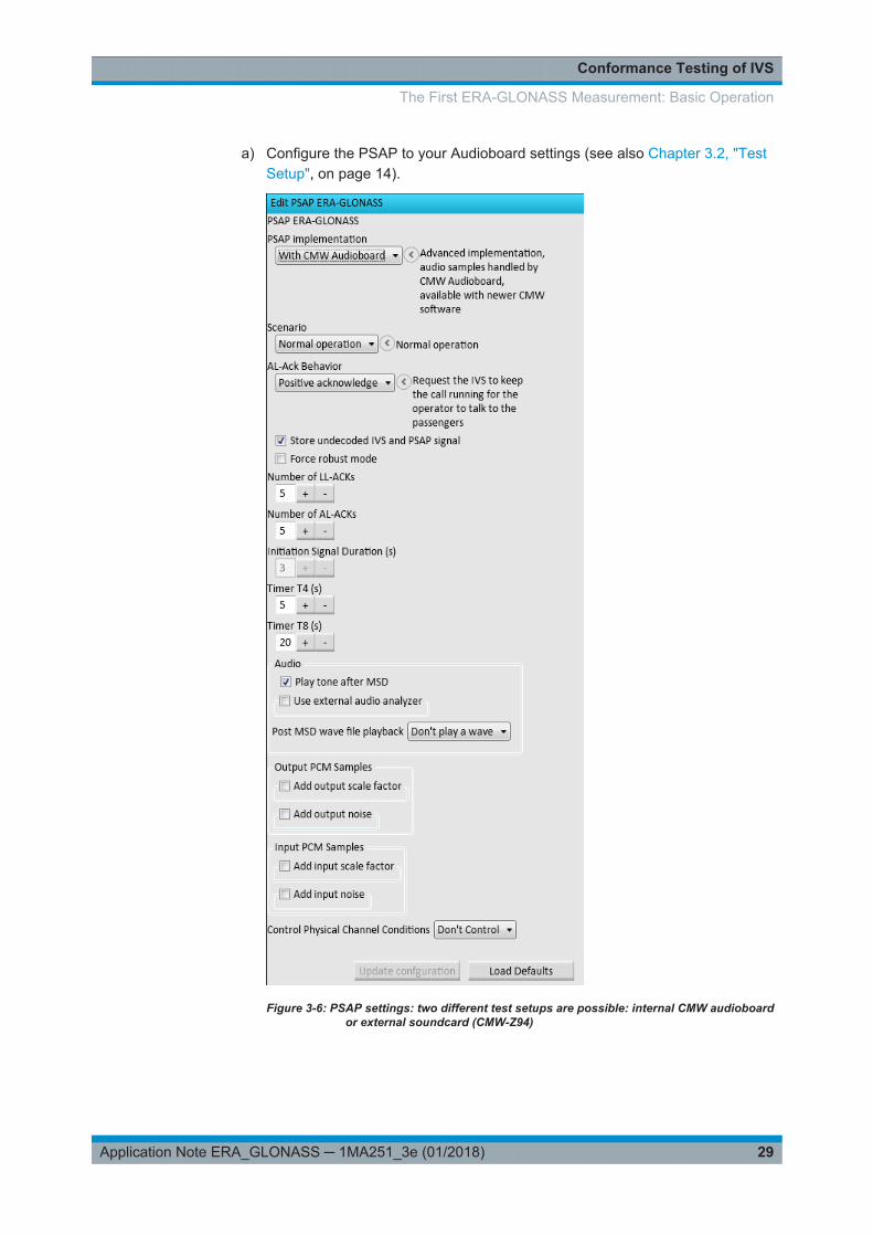
a) Configure the PSAP to your Audioboard settings (see also Chapter 3.2, "TestSetup", on page 14).
Figure 3-6: PSAP settings: two different test setups are possible: internal CMW audioboardor external soundcard (CMW-Z94)
The First ERA-GLONASS Measurement: Basic Operation

Conformance Testing of IVS
30Application Note ERA_GLONASS ─ 1MA251_3e (01/2018)
3.3.4 Performing an ERA-GLONASS call
The steps in this section set up a GSM emergency call, transfer an MSD from the IVSto the ERA-Glonass application and analyze the MSD.
The following figure shows the related ERA-GLONASS application states. The start isin "Idle" state, goes through the entire state machine to "Measurement Running" andends up in state "Datachannel Established".
1. On the right, select the "Control" view.
2. Click "Initial Config".The application validates the settings and configures the CMW and the SMBV.This may take some time, especially if you perform this action for the first time afterbooting the instruments.After a successful initial configuration, the state in the "Control" view changes from"Idle" to "Configured".
The First ERA-GLONASS Measurement: Basic Operation
Conformance Testing of IVS
31Application Note ERA_GLONASS ─ 1MA251_3e (01/2018)
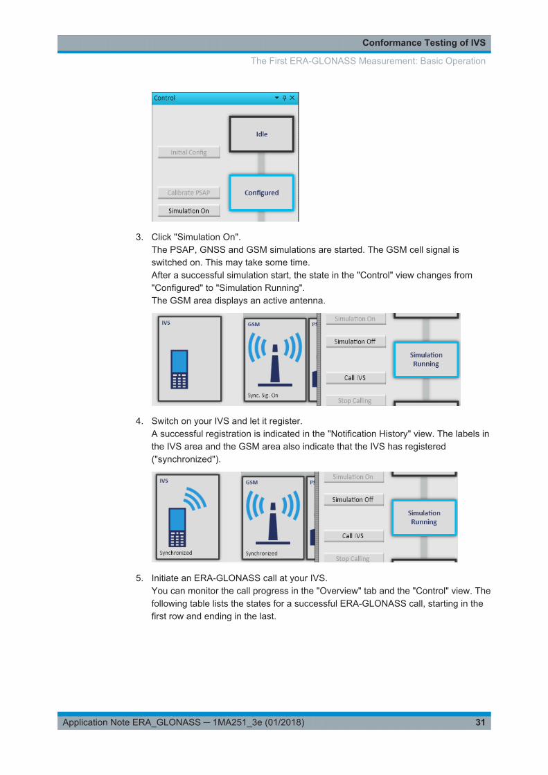
3. Click "Simulation On".The PSAP, GNSS and GSM simulations are started. The GSM cell signal isswitched on. This may take some time.After a successful simulation start, the state in the "Control" view changes from"Configured" to "Simulation Running".The GSM area displays an active antenna.
4. Switch on your IVS and let it register.A successful registration is indicated in the "Notification History" view. The labels inthe IVS area and the GSM area also indicate that the IVS has registered("synchronized").
5. Initiate an ERA-GLONASS call at your IVS.You can monitor the call progress in the "Overview" tab and the "Control" view. Thefollowing table lists the states for a successful ERA-GLONASS call, starting in thefirst row and ending in the last.
The First ERA-GLONASS Measurement: Basic Operation

Conformance Testing of IVS
32Application Note ERA_GLONASS ─ 1MA251_3e (01/2018)
IVS State GSM State PSAP State Control State Explanation
Synchronized Synchronized PSAP initialized1) SimulationRunning
IVS registered and synchronized
Connecting Connecting Call setup in progress
Call Established Call Established Ready for ERA-GLO-NASS call
Data ChannelEstablished
Data channel between IVS and PSAP estab-lished, no MSD transmission
Sending Start MeasurementRunning
PSAP requests MSD from IVS
Receiving 1st MSD part PSAP receives first MSD part
Sending NACK MSD part received
Sending LL-ACK MSD reassembled and sent to higher layers
Sending HL-ACK MSD decoded at application layer
Ready for ERA-GLO-NASS call
Data ChannelEstablished
Call still established, no MSD transmission
Sine tone transmission to the IVS
1) For the first ERA-GLONASS call, no state is indicated
6. Select the "Results Overview" view on the left.
7. Double-click the row "Decoded MSD message".
The "Detailed Results" view is automatically displayed on the right. It lists the MSDmessage contents. Here the additional data of ERA-GLONASS is shown.
The First ERA-GLONASS Measurement: Basic Operation

Conformance Testing of IVS
33Application Note ERA_GLONASS ─ 1MA251_3e (01/2018)
8. The ERA-GLONASS test software records two raw wav files for each call, one forthe uplink signal from the IVS and one for the downlink signal from the PSAP."Detailed results" displays the tracks under the tab "Wave". The following exampleshows the IVS part on top and the PSAP part on bottom. For more detailed explan-ation refer to Figure 2-2.
The First ERA-GLONASS Measurement: Basic Operation

Conformance Testing of IVS
34Application Note ERA_GLONASS ─ 1MA251_3e (01/2018)
The files are stored additionally in the installation directory of the ERA base appli-cation, for example at%PROGRAMFILES(X86)%\Rohde-Schwarz\CMW-KA09x\Complementary.To check the file contents, open the files with an external audio editor.
The First ERA-GLONASS Measurement: Basic Operation

Conformance Testing of IVS
35Application Note ERA_GLONASS ─ 1MA251_3e (01/2018)
a) The ERA software shows the recorded position under the tab "Map"
Please note that the software needs an online connection to show the map.
3.3.5 SMS commands with ERA-GLONASS
ERA-GLONASS provides the possibility to communicate between the PSAP and theIVS with the help of SMS, e.g. for sending configuration (change or query parameters)or to transmit e.g. the MSD via SMS.
Right-click the PSAP area in the section Radio Access Network on the left. Here selectthe "ERA-GLONASS SMS commands"
The settings are diplayed on the right under tab "ERA-GLONASS SMS commands"
The First ERA-GLONASS Measurement: Basic Operation

Conformance Testing of IVS
36Application Note ERA_GLONASS ─ 1MA251_3e (01/2018)
MSD via SMS
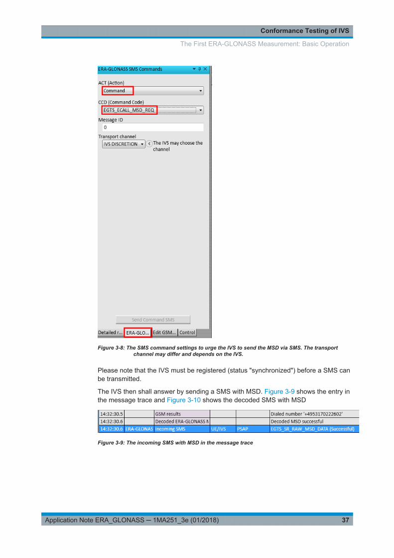
To command the IVS to tranmsit the MSD via SMS, the PSAP has to transmit a com-mand under ACTion.
Figure 3-7: Different command codes
The command code (CCD) "EGTS_ECALL_MSD_REQ" tells the IVS to transmit theMSD. The transport channel depends on the used IVS, e.g. set to "SMS"
The First ERA-GLONASS Measurement: Basic Operation
Conformance Testing of IVS
37Application Note ERA_GLONASS ─ 1MA251_3e (01/2018)
Figure 3-8: The SMS command settings to urge the IVS to send the MSD via SMS. The transportchannel may differ and depends on the IVS.
Please note that the IVS must be registered (status "synchronized") before a SMS canbe transmitted.
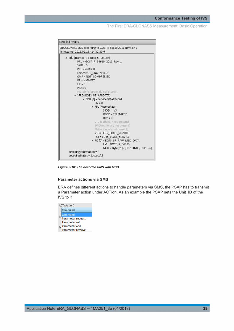
The IVS then shall answer by sending a SMS with MSD. Figure 3-9 shows the entry inthe message trace and Figure 3-10 shows the decoded SMS with MSD
Figure 3-9: The incoming SMS with MSD in the message trace
The First ERA-GLONASS Measurement: Basic Operation
Conformance Testing of IVS
38Application Note ERA_GLONASS ─ 1MA251_3e (01/2018)
Figure 3-10: The decoded SMS with MSD
Parameter actions via SMS
ERA defines different actions to handle parameters via SMS, the PSAP has to transmita Parameter action under ACTion. As an example the PSAP sets the Unit_ID of theIVS to '1'
The First ERA-GLONASS Measurement: Basic Operation

Conformance Testing of IVS
39Application Note ERA_GLONASS ─ 1MA251_3e (01/2018)
Figure 3-11: Different command codes to set parameters
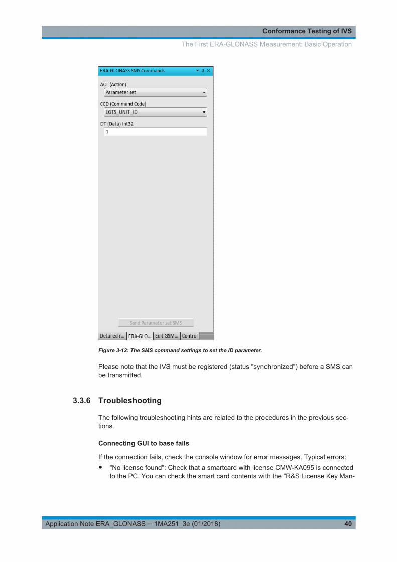
The command code (CCD) "EGTS_UNIT_ID" tells the IVS to set the unit ID (in thiscase to '1').
The First ERA-GLONASS Measurement: Basic Operation
Conformance Testing of IVS
40Application Note ERA_GLONASS ─ 1MA251_3e (01/2018)
Figure 3-12: The SMS command settings to set the ID parameter.
Please note that the IVS must be registered (status "synchronized") before a SMS canbe transmitted.
3.3.6 Troubleshooting
The following troubleshooting hints are related to the procedures in the previous sec-tions.
Connecting GUI to base fails
If the connection fails, check the console window for error messages. Typical errors:● "No license found": Check that a smartcard with license CMW-KA095 is connected
to the PC. You can check the smart card contents with the "R&S License Key Man-
The First ERA-GLONASS Measurement: Basic Operation

Conformance Testing of IVS
41Application Note ERA_GLONASS ─ 1MA251_3e (01/2018)
ager", see Windows Start menu. Close the license key manager before youattempt a connect.
● "Client register with <URL> failed": Check that the URLs in the "Base" menu arecorrect. The default settings assume that the base and the GUI are installed on thesame PC and the port 8085 is free.
Initial config fails
If the transition from state "Idle" to state "Configured" fails, check the "Notification His-tory" view. Typical errors:● "Base rejected CMW... viOpen failed...": Opening a remote control connection to
the CMW failed.– Check that you can reach the CMW via the LAN. For example send a ping
request from the PC to the CMW.– Check the VISA address string entered in on page .
● "GSM bcch number invalid for band..." or similar: Check the GSM cell settings.
Registration fails
If the registration of the IVS to the GSM or WCDMA cell fails, check the following:● Is the IVS switched on?● Is the RF cabling between the IVS and the CMW ok?● Is the correct RF connector configured in the CMW settings?
For CMW settings, see on page .● Are all GSM or WCDMA cell settings compatible to your IVS? For cell settings, see
on page .
MSD transfer fails
If the transfer of an MSD to the PSAP fails, consider the following hints for trouble-shooting:● Observe the IVS and GSM states in the overview. Is the state "Call Established"
reached or does the call setup fail?● If the call is established, monitor the PSAP state in the overview. Which is the high-
est reached state? Is an MSD part received but cannot be decoded or is no MSDreceived at all?
● If an MSD is received, but cannot be decoded, you can check the raw MSD data.In the "Results Overview" double-click the row "Raw MSD".
● For further hints, check the "Message Trace" view. It displays the exchanged eCallprotocol messages.Or check the "Log" view. If it is not visible, activate it via the "View" menu > "Show"> "Log".
The First ERA-GLONASS Measurement: Basic Operation

Conformance Testing of IVS
42Application Note ERA_GLONASS ─ 1MA251_3e (01/2018)
3.4 Measurements in Line with Specification
The conformance tests for an IVS are specified in GOST R 55530-2013 [1], chapter 6"Methods used in tests of conformity to functional requirements". These tests are listedin Table 3-2.
To perform a specific test with the ERA test software, configure the PSAP settings asindicated in the table. To access the settings, right-click the PSAP area on the left andclick "Edit PSAP Settings". The "Edit PSAP" view opens on the right.
Measurements in Line with Specification

Conformance Testing of IVS
43Application Note ERA_GLONASS ─ 1MA251_3e (01/2018)
Figure 3-13: Default PSAP settings.
If "Use external audio analyzer" is enabled, the audio signal is automatically switchedat the end of the MSD transmission to the analog audio in/out 1 connector of the CMW(instead of S/PDIF in/out). This allows the connection of an external audio analyzer likethe UPV, a handset like the CMW-Z50 or artificial heads like need for tests accordingto ITU-T specification [5] .
Measurements in Line with Specification

Conformance Testing of IVS
44Application Note ERA_GLONASS ─ 1MA251_3e (01/2018)
Table 3-2: Conformance tests
Number Name PSAP Settings Check / Pass Condition
6.1 Checking MSD transfer in automatic mode
6.1.1 Checking MSD transfer using in-band modem Default Check MSD contents: "Auto-matic activation = True", "Testcall = False"
6.1.2 Checking MSD transfer SMS Use ERA-GLONASS SMScommand: "Action= com-mand", "Command code =EGTS_ECALL_MSD_REQ","Transport channel = SMS"
Check MSD contents: "Auto-matic activation = True", "Testcall = False"
6.2 Checking MSD transfer in manual mode
6.2.1 Checking MSD transfer using in-band modem Default Check MSD contents: "Auto-matic activation = False","Test call = False"
6.2.2 Checking MSD transfer SMS Use ERA-GLONASS SMScommand: "Action= com-mand", "Command code =EGTS_ECALL_MSD_REQ","Transport channel = SMS"
Check MSD contents: "Auto-matic activation = False","Test call = False"
6.3 Checking that transferred MSD contains last knownvehicle location as for detection time of RTA event
Default Check MSD contents: "lastknown vehicle loacation deter-mined by GNSS (parametervehicle_location)"
6.4 Checking that transferred MSD contains expectedlast known vehicle location as for detection time ofRTA event
Default Check MSD contents: noinformation on the last knownvehicle location but "expectedlast known vehicle loaca-tion(parameter Recent_vehi-cle_location_n-1)
6.5 Checking that transferred MSD contains valid vehi-cle location data
Default Check MSD contents: "infor-mation on geographic loaca-tion of the vehicle (coordinatesdetermined by GNSS)"
6.6 Checking that transferred MSD contains vehiclemovement direction data
Default Check MSD contents: "infor-mation on geographic loaca-tion of the vehicle (coordinatesdetermined by GNSS), infor-mation on movement directionof the vehicle (parameterVehicleDirection)"
6.7 Checking that loud voice communication is possibleduring emergency calls
Default check duplex voice communi-cation during call
6.8 Checking IVS status indicators (for IVS in auxiliaryequipment configuration)
not available / out of scope
6.9 Checking IVS operation in Test mode Default Check MSD contents:"ECALL_TEST_NUMBER*
6.10 Checking IVS operation in "Service Station" mode(for IVS in auxiliary equipment configuration)
Default Check MSD contents
Measurements in Line with Specification

Conformance Testing of IVS
45Application Note ERA_GLONASS ─ 1MA251_3e (01/2018)
Number Name PSAP Settings Check / Pass Condition
6.11 Checking IVS operation in "Software Downloading"mode (for IVS in auxiliary equipment configuration
not available / out of scope
6.12 Checking UIM (for IVS in auxiliary equipment con-figuration)
not available / out of scope
6.13 Checking internal memory of IVS not available / out of scope
6.14 Checking operation of IVS backup battery andpower supply
not available / out of scope
6.15 Checking IVS registration in network Default Cell Status: Registered("synchronized")
6.16 Checking electric power supply and power con-sumption requirements (for IVS in auxiliary equip-ment configuration)
not available / Out of Scope
Table 3-3: Conformance tests
Number Name PSAP Settings Check / Pass Condition
6.17 Checking transfer of SMS command for settingSMS transmission number when SMS is used as aredundant data channel
Use ERA-GLONASS SMScommand: "Action= Parameterset", "Command code =EGTS_UNIT_ID",set wanted ID(1) and specify SMS number
check new SMS number viadiagnostic software
6.18 Checking transfer of SMS command for settingemergency call number used in tests
Use ERA-GLONASS SMScommand: "Action= Parameterset", "Command code =EGTS_UNIT_ID",set wanted ID(1) and specify test call number
check new test call numbervia diagnostic software
6.19 Checking transfer of SMS command for initiation oftest emergency call
Use ERA-GLONASS SMScommand: "Action= command","Command code =EGTS_ECALL_MSD_REQ","Transport channel = VOICE"
Check MSD contents: "Auto-matic activation = False","Test call = True"
6.20 Checking transfer of SMS command for repeatedMSD transfer in regard to RTA event recorded ear-lier
Use ERA-GLONASS SMScommand 2 times: "Action=command", "Command code =EGTS_ECALL_MSD_REQ","Transport channel = SMS"
receive 2 MSD's: Check MSDcontents are teh sameexcept: location and time
6.21 Checking packet transmission of firmware dataspecific to a given IVS type (for IVS in auxiliaryequipment configuration)'
not available / Out of Scope
6.22 Checking that emergency call button is protectedfrom accidental pressing
not available / Out of Scope
6.23 Checking that backlighting of emergency call buttonis available
not available / Out of Scope
Measurements in Line with Specification
Conformance Testing of IVS
46Application Note ERA_GLONASS ─ 1MA251_3e (01/2018)
3.5 Automated tests: remote control
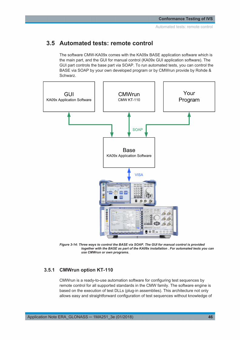
The software CMW-KA09x comes with the KA09x BASE application software which isthe main part, and the GUI for manual control (KA09x GUI application software). TheGUI part controls the base part via SOAP. To run automated tests, you can control theBASE via SOAP by your own developed program or by CMWrun provide by Rohde &Schwarz.
Figure 3-14: Three ways to control the BASE via SOAP. The GUI for manual control is providedtogether with the BASE as part of the KA09x installation . For automated tests you canuse CMWrun or own programs.
3.5.1 CMWrun option KT-110
CMWrun is a ready-to-use automation software for configuring test sequences byremote control for all supported standards in the CMW family. The software engine isbased on the execution of test DLLs (plug-in assemblies). This architecture not onlyallows easy and straightforward configuration of test sequences without knowledge of
Automated tests: remote control
Conformance Testing of IVS
47Application Note ERA_GLONASS ─ 1MA251_3e (01/2018)
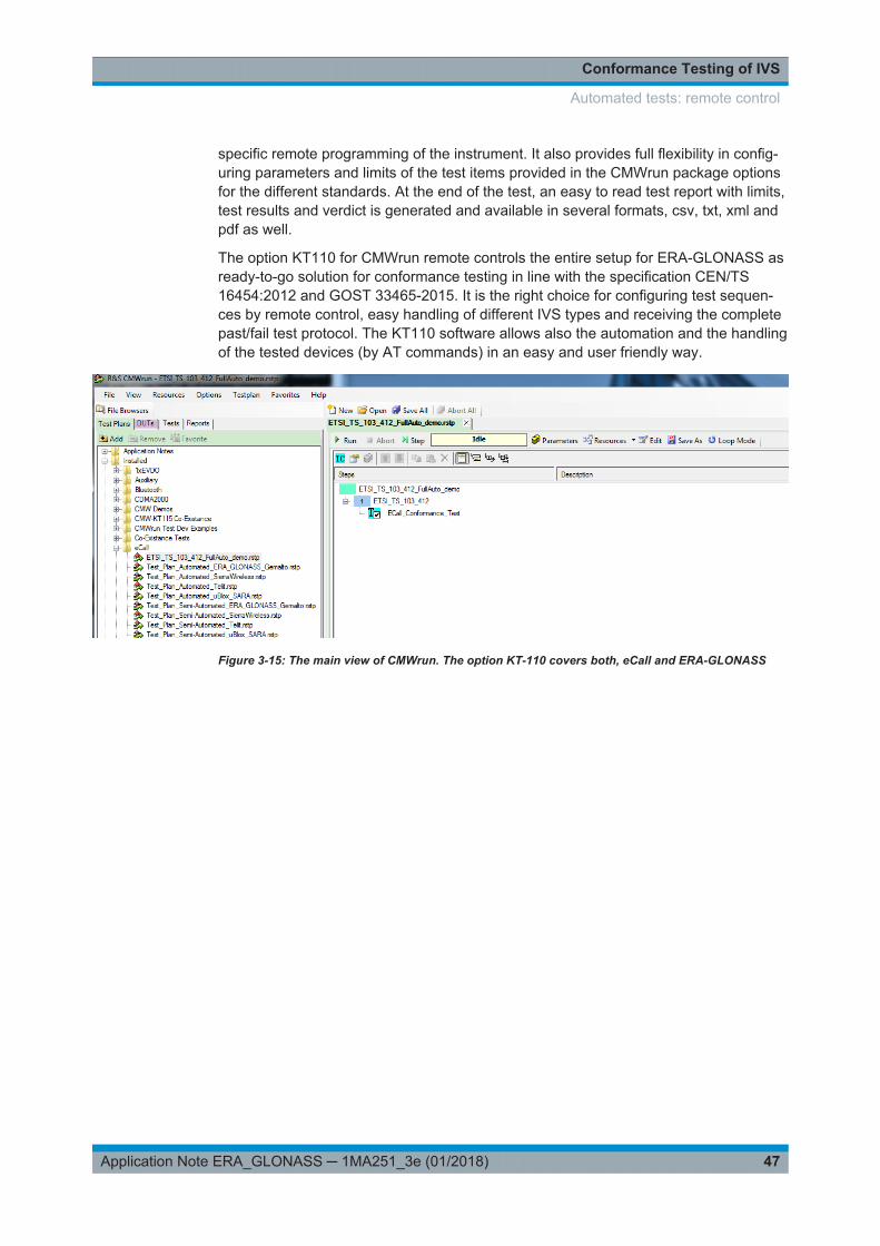
specific remote programming of the instrument. It also provides full flexibility in config-uring parameters and limits of the test items provided in the CMWrun package optionsfor the different standards. At the end of the test, an easy to read test report with limits,test results and verdict is generated and available in several formats, csv, txt, xml andpdf as well.
The option KT110 for CMWrun remote controls the entire setup for ERA-GLONASS asready-to-go solution for conformance testing in line with the specification CEN/TS16454:2012 and GOST 33465-2015. It is the right choice for configuring test sequen-ces by remote control, easy handling of different IVS types and receiving the completepast/fail test protocol. The KT110 software allows also the automation and the handlingof the tested devices (by AT commands) in an easy and user friendly way.
Figure 3-15: The main view of CMWrun. The option KT-110 covers both, eCall and ERA-GLONASS
Automated tests: remote control
Conformance Testing of IVS
48Application Note ERA_GLONASS ─ 1MA251_3e (01/2018)
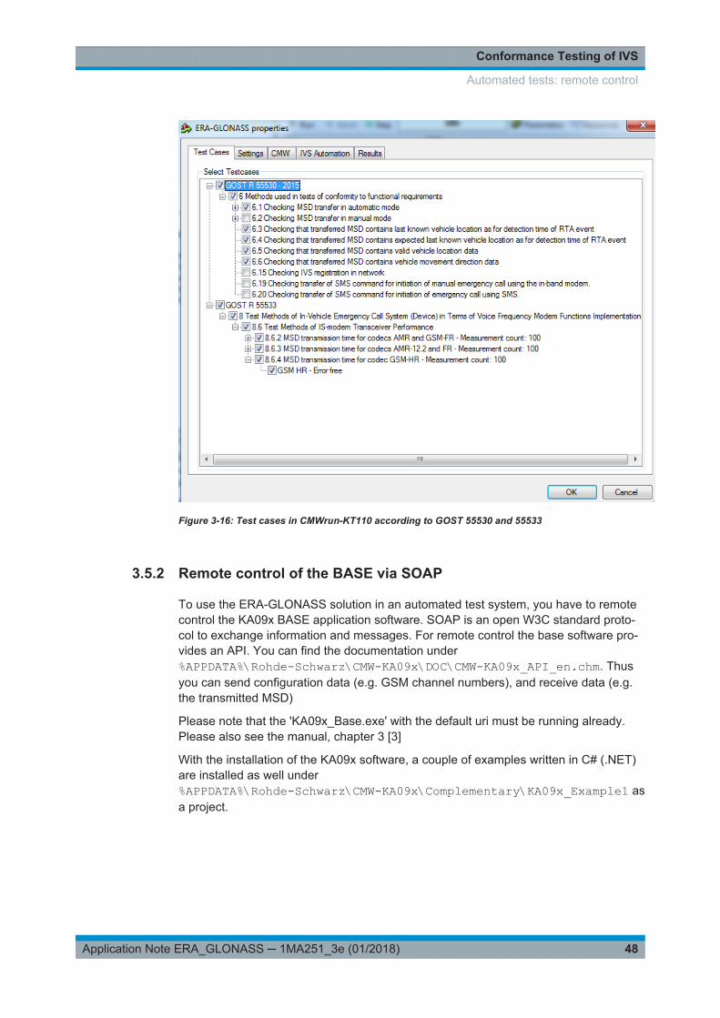
Figure 3-16: Test cases in CMWrun-KT110 according to GOST 55530 and 55533
3.5.2 Remote control of the BASE via SOAP
To use the ERA-GLONASS solution in an automated test system, you have to remotecontrol the KA09x BASE application software. SOAP is an open W3C standard proto-col to exchange information and messages. For remote control the base software pro-vides an API. You can find the documentation under%APPDATA%\Rohde-Schwarz\CMW-KA09x\DOC\CMW-KA09x_API_en.chm. Thusyou can send configuration data (e.g. GSM channel numbers), and receive data (e.g.the transmitted MSD)
Please note that the 'KA09x_Base.exe' with the default uri must be running already.Please also see the manual, chapter 3 [3]
With the installation of the KA09x software, a couple of examples written in C# (.NET)are installed as well under%APPDATA%\Rohde-Schwarz\CMW-KA09x\Complementary\KA09x_Example1 asa project.
Automated tests: remote control
Conformance Testing of IVS
49Application Note ERA_GLONASS ─ 1MA251_3e (01/2018)
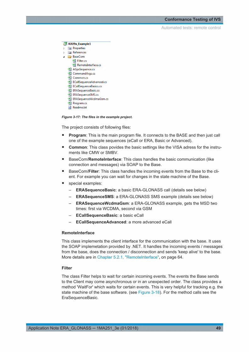
Figure 3-17: The files in the example project.
The project consists of following files:
● Program: This is the main program file. It connects to the BASE and then just callone of the example sequences (eCall or ERA, Basic or Advanced).
● Common: This class povides the basic settings like the VISA adress for the instru-ments like CMW or SMBV.
● BaseCom/RemoteInterface: This class handles the basic communication (likeconnection and messages) via SOAP to the Base.
● BaseCom/Filter: This class handles the incoming events from the Base to the cli-ent. For example you can wait for changes in the state machine of the Base.
● special examples:– ERASequenceBasic: a basic ERA-GLONASS call (details see below)– ERASequenceSMS: a ERA-GLONASS SMS example (details see below)– ERASequenceWcdmaGsm: a ERA-GLONASS example, gets the MSD two
times: first via WCDMA, second via GSM– ECallSequenceBasic: a basic eCall– ECallSequenceAdvanced: a more advanced eCall
RemoteInterface
This class implements the client interface for the communication with the base. It usesthe SOAP implemetation provided by .NET. It handles the incoming events / messagesfrom the base, does the connection / disconnection and sends 'keep alive' to the base.More details are in Chapter 5.2.1, "RemoteInterface", on page 64.
Filter
The class Filter helps to wait for certain incoming events. The events the Base sendsto the Client may come asynchronous or in an unexpected order. The class provides amethod 'WaitFor' which waits for certain events. This is very helpful for tracking e.g. thestate machine of the base software. (see Figure 3-18). For the method calls see theEraSequenceBasic.
Automated tests: remote control

Conformance Testing of IVS
50Application Note ERA_GLONASS ─ 1MA251_3e (01/2018)
Figure 3-18: The different states of the base. In remote control the appstate can be queried. Everystate change creates an event 'NewState' which can be handled in the control software.
Common
The class common provides basic settings of the used instruments common to allexamples and which are independent of the used RAN's or GNSS settings, like theVISA address or the used connector.
To talk to the instruments and simulations, certain ID's are defined:
Some global configuration is done in the class Config:
Automated tests: remote control
Conformance Testing of IVS
51Application Note ERA_GLONASS ─ 1MA251_3e (01/2018)
As an example, the configuration of the CMW is shown. The call is done in theSequence:
1. Send event 'CfgCmw' to the Base with attributes ID, Connector and VISA name
2. Wait for result (event = 'CfgResult')
Program
This is the main program. It connects to the Base via SOAP and selects the wantedsequence.
First it creates a new object named "r" of type Remoteinterface and a new objectnamed "f" of type filter.
Automated tests: remote control

Conformance Testing of IVS
52Application Note ERA_GLONASS ─ 1MA251_3e (01/2018)
It connects to the base via the method 'connect' of "r". The default URL of the base isused. Then it just calls the wanted sequence.
ERASequenceBasic
This sequence executes the ERA basic example. It has following steps:
1. ResetBase
2. InitialConfig
3. DoConfiguration
4. SimOn
5. WaitForCall
6. Waiting for the MSD transfer and show the MSD
7. Waiting for ACK
● Reset of the Base (Call Common.resetBase(f,r);)
Automated tests: remote control

Conformance Testing of IVS
53Application Note ERA_GLONASS ─ 1MA251_3e (01/2018)
1. Send the event 'ResetBase'2. Wait until the reset is done with a timeout of 10 s (event = 'BaseDidReset')
● The basic configuration is done in 'InitialConfig'
– Configuration of the setup (used instruments)
Send event 'CfgSetup' to the Base with attributes defined in 'common'– Which CMW and SMBV is used (defined in common)
– Configuration of a GNSS scenario (GLONASS: City Scenario Moscow)
1. Send event 'CfgGlonassCity' to the Base with attributes 'Moscow'2. Wait for result (event = 'CfgResult')
– Configuration of the GSM cell settings
1. Send event 'CfgGSM' to the Base with attributes 'GsmBand and Channels'2. Wait for result (event = 'CfgResult')
– Configuration of the PSAP settings
Automated tests: remote control

Conformance Testing of IVS
54Application Note ERA_GLONASS ─ 1MA251_3e (01/2018)
1. Send event 'CfgEraGlonassPsap' to the Base with different attributes2. Wait for result (event = 'CfgResult')
● Execute all configurations (including a license check and settings of all used instru-ments) and wait until everything is done (Call Common.DoConfiguration(f,r);)
1. After configuring with InitialConfig, send the event 'DoConfiguration'2. Wait for a state transition with a timeout (common.TimeOut.IDLE_TO_CFG)(event = 'NewState')3. Ceck if the current state is 'CONFIGURED' otherwise something went wrong
● Start the simulation (Call Common.simOn(f,r);)
1. Switch on the simulation by the event 'SimulationOn'2. Wait for a state transition (event = 'NewState', TimeOut.CFG_TO_SIMON)3. Ceck if the current state is 'SIMULATION_STARTED' otherwise something wentwrong
● Wait for the ERA-GLONASS call (Call Common.waitForCall(f,r);)
1. No event from the client to send, the call has to be initialized by the IVS2. Wait for a state transition (event = 'NewState', default timeout)3. Ceck if the current state is 'DATACH_ESTABLISHED' otherwise something wentwrong
● Receive the MSDThe receiving of the MSD is done in three parts:– Wait for the start of the transmission of the MSD
Automated tests: remote control

Conformance Testing of IVS
55Application Note ERA_GLONASS ─ 1MA251_3e (01/2018)
1. Wait for a state transition (event = 'NewState', default timeout)2. Ceck if the current state is 'MEASUREMENT_RUNNING' (the MSD transferis in progress), otherwise something went wrong
– Wait until the whole MSD is successfully received (Call Common.waitForSuc-cessfullRawMSD(f,r);)
1. The IVS may transmit the MSD in different redundancy versions at a maxi-mum of eight times. This is handled by the program with the do-while loop.2. Wait for state 'RawMsdVoice' with a timeout of 10 seconds)3. If the PSAP is able to receive the MSD successfully, the 'rawMsd.msd' is dif-ferent from NULL, return to mainprogram, otherwise stay in the loop
– Output the decoded MSD part
1. Wait for event 'DecodedEraGlonassMsdV1'2. Output the decoded MSD (V1 is expected, depends on the IVS)3. Check for additional data (DecodedEraGlonassExtV1)
● Wait for ACKs
Automated tests: remote control

Conformance Testing of IVS
56Application Note ERA_GLONASS ─ 1MA251_3e (01/2018)
1. No event from the client to send, the PSAP sends the ACK's to IVS after suc-cessful decoding of the MSD.2. Wait for a state transition (event = 'NewState', timeout 10 seconds)3. Ceck if the current state is 'DATACH_ESTABLISHED' otherwise something wentwrong
ERASequenceSMS
This sequence executes the ERA SMS example with a MSD request.
Please note that the first steps are the same like in the ERASequenceBasic:
● Reset of the Base● The basic configuration is done in 'InitialConfig'● Execute all configurations (including a license check and settings of all used instru-
ments) and wait until everything is done● Start the simulation
The additional steps for the SMS are
● Wait for the registration of the IVS to the network
1. In a do...while loop the status of the Cell is queried (Wait for event 'GsmCell-SignalStateCmw')2. If the status is 'SYNC', exit the loop
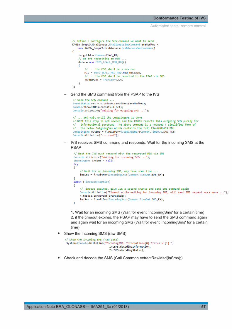
● Request a SMS with a MSD (Call Common.requestMsdViaEgtsEcallMsdReq(f,r);).This contains three parts:– Configure the wanted SMS command
Automated tests: remote control
Conformance Testing of IVS
57Application Note ERA_GLONASS ─ 1MA251_3e (01/2018)
– Send the SMS command from the PSAP to the IVS
– IVS receives SMS command and responds. Wait for the incoming SMS at thePSAP
1. Wait for an incoming SMS (Wait for event 'IncomingSms' for a certain time)2. if the timeout expires, the PSAP may have to send the SMS command againand again wait for an incoming SMS (Wait for event 'IncomingSms' for a certaintime)
● Show the Incoming SMS (raw SMS)
● Check and decode the SMS (Call Common.extractRawMsd(inSms);)
Automated tests: remote control
Conformance Testing of IVS
58Application Note ERA_GLONASS ─ 1MA251_3e (01/2018)
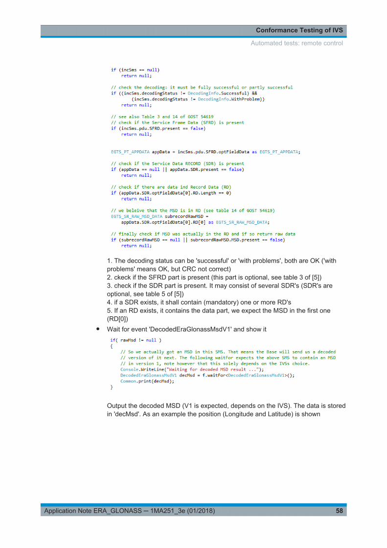
1. The decoding status can be 'successful' or 'with problems', both are OK ('withproblems' means OK, but CRC not correct)2. ckeck if the SFRD part is present (this part is optional, see table 3 of [5])3. check if the SDR part is present. It may consist of several SDR's (SDR's areoptional, see table 5 of [5])4. if a SDR exists, it shall contain (mandatory) one or more RD's5. If an RD exists, it contains the data part, we expect the MSD in the first one(RD[0])
● Wait for event 'DecodedEraGlonassMsdV1' and show it
Output the decoded MSD (V1 is expected, depends on the IVS). The data is storedin 'decMsd'. As an example the position (Longitude and Latitude) is shown
Automated tests: remote control

GNSS Performance Testing
59Application Note ERA_GLONASS ─ 1MA251_3e (01/2018)
4 GNSS Performance TestingThe standard GOST-33471-2015 (55534) [6] defines test methods for the navigationmodule of the ERA IVS.
The required tests include:● Position accuracy● Tracking sensitivity● Acquisition accuracy● Time to first fix (TTFF)
The solution presented here is intended for tests at the module level and at the devicelevel. This solution features the software CMWrun for a fully automatic test configura-tion, scheduling, DUT configuration, data analysis and test report generation. Theoption SMBV-K360 for CMWrun controls remotely the SMBV and permits all basicparameters settings, such as vehicle simulation, GNSS simulation or level, to be man-aged directly. As a result, measurements are fully reproducible. The solution coverstest cases TC 5.1 to TC 5.15 of the specification.
4.1 Test Setup
Figure 4-1 shows the test setup.
Figure 4-1: Test setup for the GNSS performance test
Test Setup

GNSS Performance Testing
60Application Note ERA_GLONASS ─ 1MA251_3e (01/2018)
The SMBV simulates GNSS signals, such as GLONASS and or GPS, that are used bythe IVS for positioning. The CMWrun software installed on an external PC sets neces-sary parameters for ERA-GLONASS tests on the SMBV (which needs the SMBV-K360) and fully remote controls the SMBV (via LAN). CMWrun also controls the IVSvia serial interface. It is not necessary here to delve into the operation of the SMBV.For more details on the SMBV see Chapter 3.2.2, "SMBV Vector Signal Generator",on page 17.
Needed GNSS options
Following software options of the SMBV are needed for ERA-GLONASS performancetests:
Table 4-1: Options and test cases
Software configuration Option SMBV Comments
Minimum requirements
GPS K44
GLONASS K94
GNSS enhanced K92
Extension to 12 satellite K91
Extension to 24 satellite K96
To add for full coverage
SBAS K110 for TC 5.5
Antenna pattern K102 for TC 5.8
Test automation
ERA -Glonass test suite K360 with CMWrun
4.2 Performance Tests
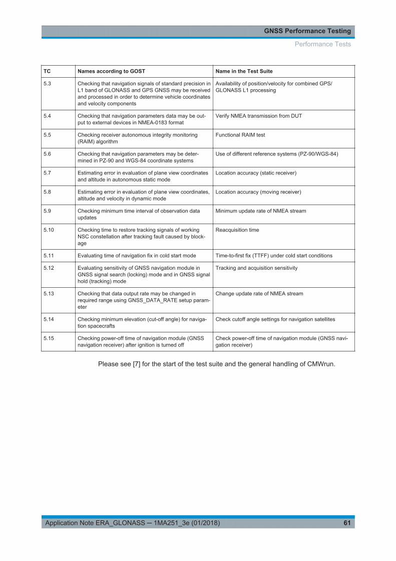
The Test Suite SMBV-K360 together with CMWrun supports following test according toGOST-55534 / 33471:
Table 4-2: Covered test cases
TC Names according to GOST Name in the Test Suite
5.1 Checking that navigation signals of standard precision inL1 band of GLONASS GNSS may be received and pro-cessed in order to determine vehicle coordinates and itsvelocity components
Availability of position/velocity for GLONASS L1
5.2 Checking that navigation signals of standard precision inL1 band of GPS GNSS may be received and processedin order to determine vehicle coordinates and velocitycomponents
Availability of position/velocity for GPS L1
Performance Tests
GNSS Performance Testing
61Application Note ERA_GLONASS ─ 1MA251_3e (01/2018)
TC Names according to GOST Name in the Test Suite
5.3 Checking that navigation signals of standard precision inL1 band of GLONASS and GPS GNSS may be receivedand processed in order to determine vehicle coordinatesand velocity components
Availability of position/velocity for combined GPS/GLONASS L1 processing
5.4 Checking that navigation parameters data may be out-put to external devices in NMEA-0183 format
Verify NMEA transmission from DUT
5.5 Checking receiver autonomous integrity monitoring(RAIM) algorithm
Functional RAIM test
5.6 Checking that navigation parameters may be deter-mined in PZ-90 and WGS-84 coordinate systems
Use of different reference systems (PZ-90/WGS-84)
5.7 Estimating error in evaluation of plane view coordinatesand altitude in autonomous static mode
Location accuracy (static receiver)
5.8 Estimating error in evaluation of plane view coordinates,altitude and velocity in dynamic mode
Location accuracy (moving receiver)
5.9 Checking minimum time interval of observation dataupdates
Minimum update rate of NMEA stream
5.10 Checking time to restore tracking signals of workingNSC constellation after tracking fault caused by block-age
Reacquisition time
5.11 Evaluating time of navigation fix in cold start mode Time-to-first fix (TTFF) under cold start conditions
5.12 Evaluating sensitivity of GNSS navigation module inGNSS signal search (locking) mode and in GNSS signalhold (tracking) mode
Tracking and acquisition sensitivity
5.13 Checking that data output rate may be changed inrequired range using GNSS_DATA_RATE setup param-eter
Change update rate of NMEA stream
5.14 Checking minimum elevation (cut-off angle) for naviga-tion spacecrafts
Check cutoff angle settings for navigation satellites
5.15 Checking power-off time of navigation module (GNSSnavigation receiver) after ignition is turned off
Check power-off time of navigation module (GNSS navi-gation receiver)
Please see [7] for the start of the test suite and the general handling of CMWrun.
Performance Tests
GNSS Performance Testing
62Application Note ERA_GLONASS ─ 1MA251_3e (01/2018)
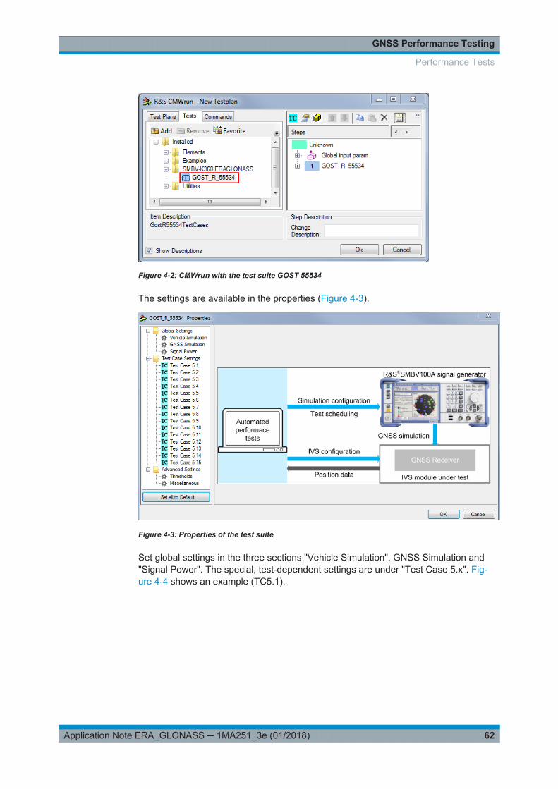
Figure 4-2: CMWrun with the test suite GOST 55534
The settings are available in the properties (Figure 4-3).
Figure 4-3: Properties of the test suite
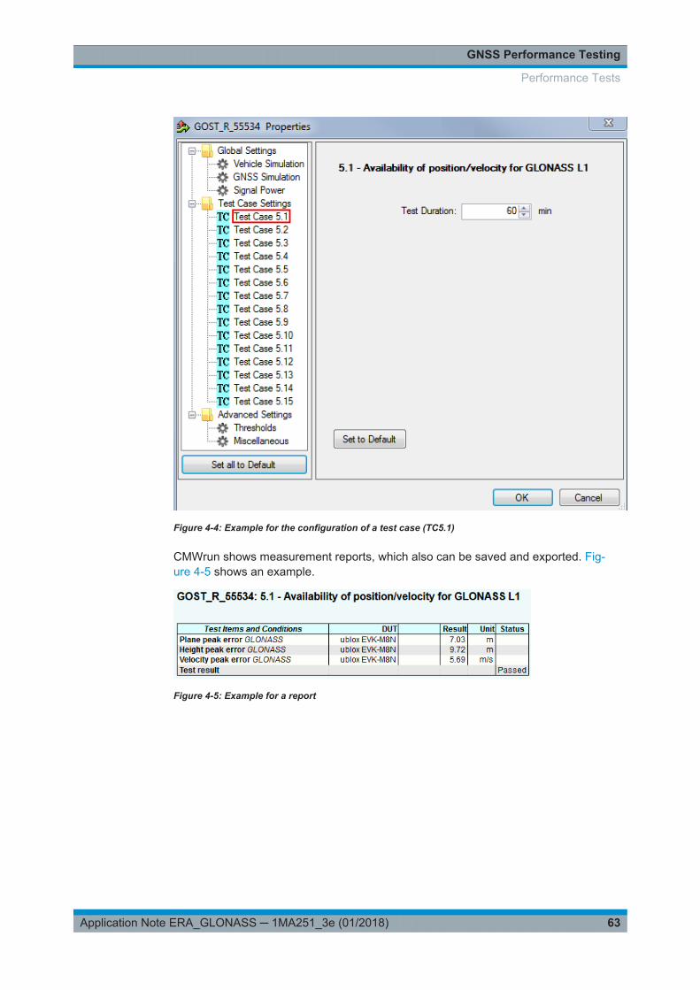
Set global settings in the three sections "Vehicle Simulation", GNSS Simulation and"Signal Power". The special, test-dependent settings are under "Test Case 5.x". Fig-ure 4-4 shows an example (TC5.1).
Performance Tests
GNSS Performance Testing
63Application Note ERA_GLONASS ─ 1MA251_3e (01/2018)
Figure 4-4: Example for the configuration of a test case (TC5.1)
CMWrun shows measurement reports, which also can be saved and exported. Fig-ure 4-5 shows an example.
Figure 4-5: Example for a report
Performance Tests
Appendix
64Application Note ERA_GLONASS ─ 1MA251_3e (01/2018)
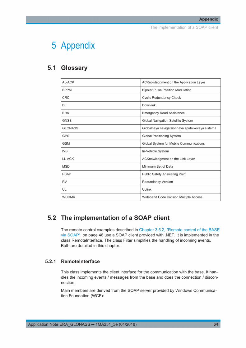
5 Appendix
5.1 Glossary
AL-ACK ACKnowledgment on the Application Layer
BPPM Bipolar Pulse Position Modulation
CRC Cyclic Redundancy Check
DL Downlink
ERA Emergency Road Assistance
GNSS Global Navigation Satellite System
GLONASS Globalnaya navigatsionnaya sputnikovaya sistema
GPS Global Positioning System
GSM Global System for Mobile Communications
IVS In-Vehicle System
LL-ACK ACKnowledgment on the Link Layer
MSD Minimum Set of Data
PSAP Public Safety Answering Point
RV Redundancy Version
UL Uplink
WCDMA Wideband Code Division Multiple Access
5.2 The implementation of a SOAP client
The remote control examples described in Chapter 3.5.2, "Remote control of the BASEvia SOAP", on page 48 use a SOAP client provided with .NET. It is implemented in theclass RemoteInterface. The class Filter simplifies the handling of incoming events.Both are detailed in this chapter.
5.2.1 RemoteInterface
This class implements the client interface for the communication with the base. It han-dles the incoming events / messages from the base and does the connection / discon-nection.
Main members are derived from the SOAP server provided by Windows Communica-tion Foundation (WCF):
The implementation of a SOAP client

Appendix
65Application Note ERA_GLONASS ─ 1MA251_3e (01/2018)
Figure 5-1: 'host' is the the main member of the SOAP implementation via DOT.NET. eventSender oftype 'IToBase32' handles the events to send to the base
Figure 5-2: Basic communications in SOAP
1. The Base is in idle status and listens to incoming events
2. First thew client side starts its service ('StartClientService')
3. The client has to register at the Base with his own URL
4. The base answers with a 'Welcome'
5. Both, base and client, have to send 'KeepAlive' in certain intervals, otherwise thebase severs the connection
The implementation of a SOAP client
Appendix
66Application Note ERA_GLONASS ─ 1MA251_3e (01/2018)
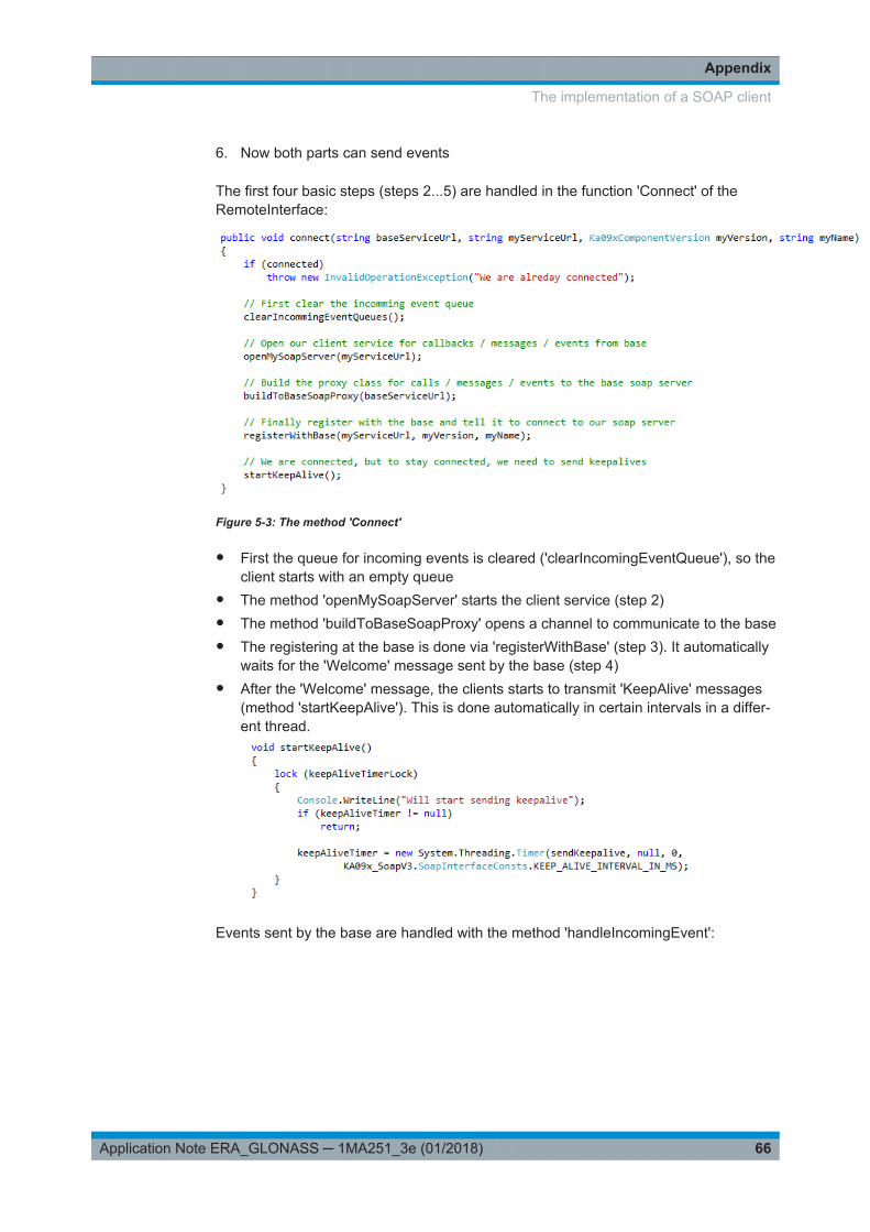
6. Now both parts can send events
The first four basic steps (steps 2...5) are handled in the function 'Connect' of theRemoteInterface:
Figure 5-3: The method 'Connect'
● First the queue for incoming events is cleared ('clearIncomingEventQueue'), so theclient starts with an empty queue
● The method 'openMySoapServer' starts the client service (step 2)● The method 'buildToBaseSoapProxy' opens a channel to communicate to the base● The registering at the base is done via 'registerWithBase' (step 3). It automatically
waits for the 'Welcome' message sent by the base (step 4)● After the 'Welcome' message, the clients starts to transmit 'KeepAlive' messages
(method 'startKeepAlive'). This is done automatically in certain intervals in a differ-ent thread.
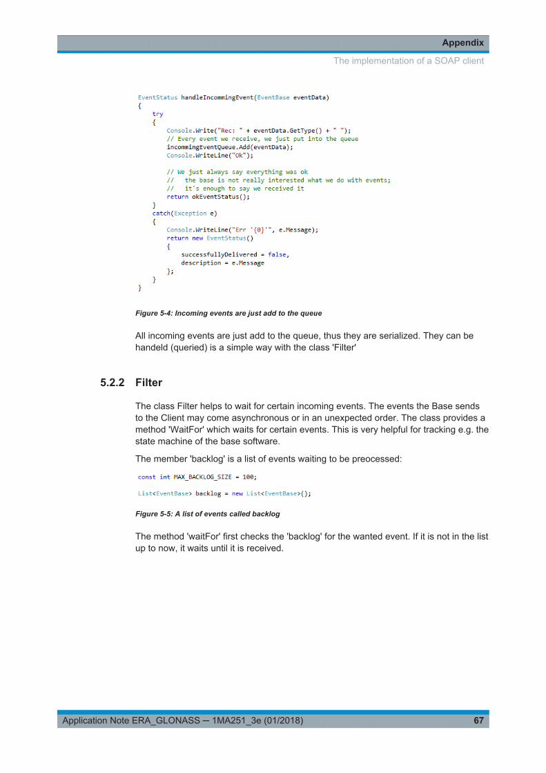
Events sent by the base are handled with the method 'handleIncomingEvent':
The implementation of a SOAP client
Appendix
67Application Note ERA_GLONASS ─ 1MA251_3e (01/2018)
Figure 5-4: Incoming events are just add to the queue
All incoming events are just add to the queue, thus they are serialized. They can behandeld (queried) is a simple way with the class 'Filter'
5.2.2 Filter
The class Filter helps to wait for certain incoming events. The events the Base sendsto the Client may come asynchronous or in an unexpected order. The class provides amethod 'WaitFor' which waits for certain events. This is very helpful for tracking e.g. thestate machine of the base software.
The member 'backlog' is a list of events waiting to be preocessed:
Figure 5-5: A list of events called backlog
The method 'waitFor' first checks the 'backlog' for the wanted event. If it is not in the listup to now, it waits until it is received.
The implementation of a SOAP client

Appendix
68Application Note ERA_GLONASS ─ 1MA251_3e (01/2018)
Figure 5-6: The method 'waitFor'
To provide a more convenient way, a generic method is also provided as a wrapper:
Figure 5-7: The generic wrapper 'waitFor'
5.3 References
[1] CEN: CEN/TS 16454:2015: Intelligent transport systems - ESafety - ECall endto end conformance testing, September 2015
References

Appendix
69Application Note ERA_GLONASS ─ 1MA251_3e (01/2018)
[2] 3GPP: TS26.267 :Technical Specification Group Services and SystemAspects; eCall Data Transfer; In-band modem solution; General descriptionV12.0.0., December 2012
[3] User Manual: Test Software for eCall, CMW-KA094,Rohde & Schwarz, 2015
[4] GOST R 55530-2013: Road Accident Emergency Response System: Func-tional test methods of IVS and data transfer protocols
[5] GOST R 54619-2011: Road Accident Emergency Response System: Protocolof Data Transmission from In-Vehicle Emergency Call System/Device to Emer-gency Response System Infrastructure
[6] GOST R 55534-2013: Road Accident Emergency Response System: Testmethods for navigation modules of in-vehicle emergency call systems
[7] User Manual: ERA-GLONASS Test Suite, SMBV-K360,Rohde & Schwarz, 2017
5.4 Additional Information
Please send your comments and suggestions regarding this white paper to
5.5 Ordering Information
Please contact your local Rohde & Schwarz sales office for further assistance.
CMW500 Radio Communication Tester
Base Unit CMW500
CMW500 Mainframe 03 CMW-PS503 1208.7154.02
Front Panel with Display H600B CMW-S600B 1201.0102.03
BB Flexible Link H550B CMW-S550B 1202.4801.03
RF Frontend (Basic) H590A CMW-S590A 1202.5108.02
Signaling Unit Universal B200A CMW-B200A 1202.6104.02
GSM Signaling option CMW-B210A 1202.6204.02
Signaling Unit Wideband, B300B CMW-B300B 1202.6304.03
Audio Analyzer/Generator H400B CMW-B400B 1207.8457.02
Speech codec H405A CMW-B405A 1207.8257.02
GSM GPRS EDGE Rel. 6, Basicsignaling
CMW-KS200 1203.0600.02
GSM GPRS EDGE R6, advancedsignaling
CMW-KS210 1203.9759.02
Ordering Information
Appendix
70Application Note ERA_GLONASS ─ 1MA251_3e (01/2018)
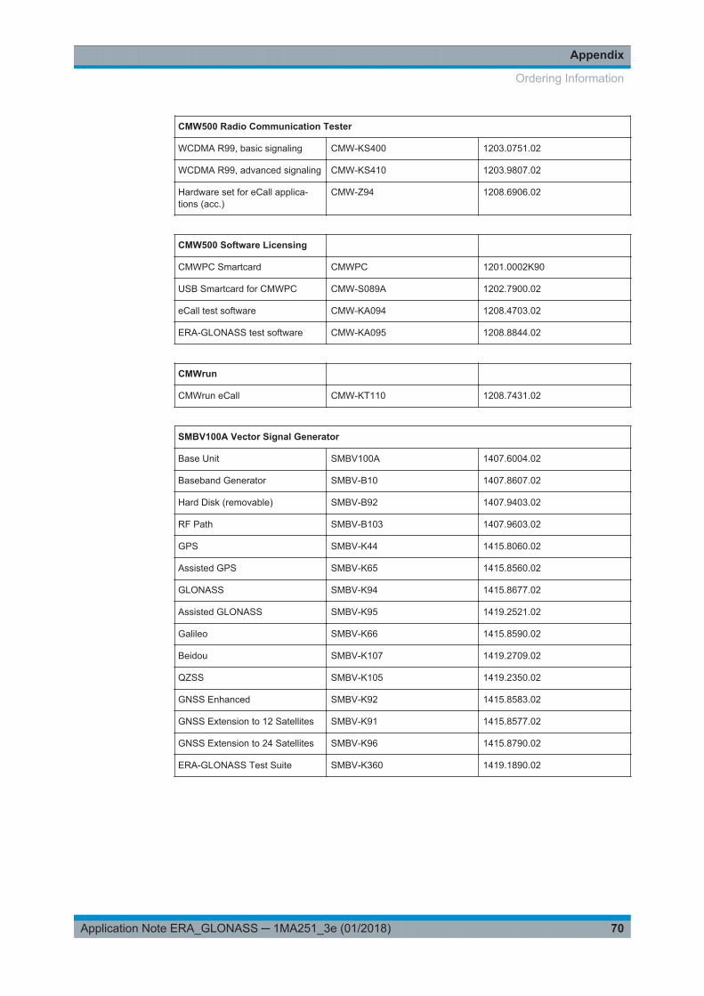
CMW500 Radio Communication Tester
WCDMA R99, basic signaling CMW-KS400 1203.0751.02
WCDMA R99, advanced signaling CMW-KS410 1203.9807.02
Hardware set for eCall applica-tions (acc.)
CMW-Z94 1208.6906.02
CMW500 Software Licensing
CMWPC Smartcard CMWPC 1201.0002K90
USB Smartcard for CMWPC CMW-S089A 1202.7900.02
eCall test software CMW-KA094 1208.4703.02
ERA-GLONASS test software CMW-KA095 1208.8844.02
CMWrun
CMWrun eCall CMW-KT110 1208.7431.02
SMBV100A Vector Signal Generator
Base Unit SMBV100A 1407.6004.02
Baseband Generator SMBV-B10 1407.8607.02
Hard Disk (removable) SMBV-B92 1407.9403.02
RF Path SMBV-B103 1407.9603.02
GPS SMBV-K44 1415.8060.02
Assisted GPS SMBV-K65 1415.8560.02
GLONASS SMBV-K94 1415.8677.02
Assisted GLONASS SMBV-K95 1419.2521.02
Galileo SMBV-K66 1415.8590.02
Beidou SMBV-K107 1419.2709.02
QZSS SMBV-K105 1419.2350.02
GNSS Enhanced SMBV-K92 1415.8583.02
GNSS Extension to 12 Satellites SMBV-K91 1415.8577.02
GNSS Extension to 24 Satellites SMBV-K96 1415.8790.02
ERA-GLONASS Test Suite SMBV-K360 1419.1890.02
Ordering Information

Rohde & Schwarz
71Application Note ERA_GLONASS ─ 1MA251_3e (01/2018)
6 Rohde & SchwarzThe Rohde & Schwarz electronics group offers innovative solutions in the followingbusiness fields: test and measurement, broadcast and media, secure communications,cybersecurity, monitoring and network testing. Founded more than 80 years ago, theindependent company has an extensive sales and service network with locations inmore than 70 countries.
The electronics group ranks among the world market leaders in its established busi-ness fields. The company is headquartered in Munich, Germany. It also has regionalheadquarters in Singapore and Columbia, Maryland, USA, to manage its operations inthese regions.
Sustainable product design
● Environmental compatibility and eco-footprint● Energy efficiency and low emissions● Longevity and optimized total cost of ownership
Certified Quality Management
ISO 9001Certified Environmental Management
ISO 14001
Contact us
● Europe, Africa, Middle East | [email protected]+49 89 4129 12345
● North America | [email protected] (1-888-837-8772)
● Latin America | [email protected]+1-410-910-7988
● Asia Pacific | [email protected]+65 65 13 04 88
● China | [email protected]+86-800-810-8228 / +86-400-650-5896
Rohde & Schwarz GmbH & Co. KG
Mühldorfstraße 15 | D - 81671 München
+ 49 89 4129 - 0 | Fax + 49 89 4129 – 13777
www.rohde-schwarz.com
This application note and the supplied programs may only be used subject to observance of the conditionsof use set forth in the download area of the Rohde & Schwarz website.
R&S® is a registered trademark of Rohde & Schwarz GmbH & Co. KG. Trade names are trademarks oftheir owners.