Embed Size (px)
Citation preview

PRODUCT
APPLICATIONNOTE 183
23.06.2020 DFF-FO_0284 Page 1 von 15
Equivalent DC-current in FAULHABER SC and MC
Summary
The datasheets of FAULHABER motors specify different currents such as the no-load current and
the rated current expressed as DC or equivalent DC-currents.
Measuring these currents of a motor connected to either a SpeedController (SC) or MotionController
(MC) can be confusing. So here is which currents and voltages can be measurend and how to
interprete them.
Applies To
All FAULHABER MCs and SCs.
Motor drivers using a PWM power stage.
Description
When configuring a FAULHABER SC or MC any current value – the rated, continuous and the peak-
currents are expected to be the current at the motor, expressed either as a DC-current for a brushed
DC-motor or an equivalent DC-current for a brushless DC-motor (BLDC).
Especially for the brushless ones it is however difficult to acutally measure these currents.
The general setup typically is like in Figure 1.
Either a brushed DC or a brushless DC motor is connected to a driver which is connected to a power supply.
Imotor
Umotor
Idriver
Udriver
P = Idriver x Udriver = Imotor x Umotor
Figure 1 Currents and voltages at a motor driver

Faulhaber Product Application Note 183 Page 2 von 15
Currents and voltages at a brushed DC-motor
The driver typically reduces the supply voltage Udriver by means of PWM to the required voltage at the motor Umotor.
The resulting voltage is required to compensate the EMF of the motor and to drive the necessary current across the winding resistance.
equivalent circuit of a brushed DC-motor current and voltages at a brushed DC-motor
Figure 2 Description of a brushed DC-motor
In coreless motors the inductive part of the winding can be ignored for this calculation. So for a given working point the equation would be:
≈ + = + (1)
Where RA is the terminal resistance of the motor, iA is the motor current, n the speed and kE the back-EMF constant. At any given voltage the voltage is divided into a part which is lost at the ter-minal resistance and a part which compensates the back-EMF.
ui(t)
RLiA(t)
)()()(
tutRidt
tdiLU
iA
A
S
t
Us
ui(t)
iA(t)
RA iA
n kE
T, iA
n
Us
Figure 3 Working diagram of a coreless DC-motor

Faulhaber Product Application Note 183 Page 3 von 15
There are additional losses e.g. at the brushes of a copper-graphite commutated mo-
tor but these will be neglected here.
In reality ui is not constant, not even at a constant speed because the voltage generated in the winding is commutated by the mechanic commutator having a finite number of segments – see Figure 2. So the equation (1) holds for the mean value of the voltages and currents only. But that’s how the kE is determined.
So for a brushed DC-motor the voltage and the current can easily be measured using a multimeter in between the driver and the motor using the DC-measuring range1.
Using a multimeter in RMS mode might lead to wrong values.
1 The effective power of a motor connected to a DC supply can be calculated by = . US is a constant voltage whereas iA is not constant but periodic. iA can be expressed by a Fourrier series and using this Pmotor can be expressed as = + ∑ cos + sin #$%& #. As the mean values of any constant voltage with the harmonics of the currents equals 0 in any signal period the harmonic parts do contribute to the reactive power only but don’t actually contribute to the effective power.

Faulhaber Product Application Note 183 Page 4 von 15
Example
Let’s use a 2342S024 CR brushed DC motor having copper-graphite brushes.
Relevant parameters of the 12V and the 24V version are:
2342S012 CR 2342S024 CR Unit
Terminal resistance R 1.9 7.1 Ω
Back-EMF constant kE 1.4 2.73 mV / min-1
Torque constant kM 18.57 37.83 mNm/A
Rated torque 17 17 mNm
Rated current 1.5 0.78 A
Rated speed 6090 6470 min-1
So if the motor would be conneted to a driver which is supplied with 24V and operated at a speed of 5000 min-1 @ 10mNm the operating point would be:
2342S012 CR 2342S024 CR Unit
motor current: iA = T / kM 0.74 0.38 A
Back-EMF: ui = kE x n 7.0 13.65 V
motor voltage Us = RA iA + n kE 8.4 16.4 V
duty cycle d 35.1 68.2 %
Idriver 0.26 0.26 A
Figure 4 Operating area of the 2342S CR motor

Faulhaber Product Application Note 183 Page 5 von 15
To generate the US out of the Udriver the driver applies a PWM with the ratio
' = ()*
100%
Vice versa the supply current is reduced by the same factor compared to the motor current:
= ' ()* (2)
.()* = .' = ' (3)
Using a different voltage version of the motor results in a diffent motor voltage and motor current. The actual power values however don’t change which can easily be confirmed at the mechanic side, where the indentical working point (speed / torque) has been selected or at the supply side, where the consumed current at the same supply voltage is identical too.
This behavior is referred to as a so called variable DC-transformer as the DC values at the input side are transformed into DC-values (voltage / current) at the motor side by the ratio d.
But – obviously – the motor current can’t be measurend at the supply side of the driver.
As the motor current is reduced by a variable factor depending on the actual
duty-cycle, a motor used at different working points can’t be protected by a
fuse at the supply side of the driver which can be easily confirmed in the ex-
ample. A rated motor current of 1.4A for the 12V version results in:
Idriver = 168mA @ d=12% - holding at n=0
Idriver = 700mA @ d=50%
Idriver = 1400mA @ d=100%
The motor driver can measure the real motor current and therefore can limit
the actual current to the configured values. So even when only operating a
DC-motor, using a motor driver can offer some additional protection for the
motor which otherwise could easily be overloaded.

Faulhaber Product Application Note 183 Page 6 von 15
Currents and voltages at a brushless DC-motor (BLDC)
While at a brushed DC-motor at a steady state voltages and currents are constant and can be measured using a multimeter the situation is a little more complex at a BLDC-motor.
In a brushed DC-motor the mechanic commutator will commutate the current into the parts of the winding where the magnetic field generated by the current is offset to the magnetic field of the per-manent magnet by 90°to generate the maximum torque/current.
In a BLDC-motor the magnet is the moving part of the motor and the the electronic commutation has to rotate the magnetic field generated by the three currents synchronously and relative to the magnet to generate the required torque.
So in addition to the reduction of the supply voltage by means of PWM the current is to be moved around the winding system by the electronics.
FAULHABER BLDC motors generate a sinusoidal back EMF. As with the brushed DC-motors the amplitude of the generated voltage is proportional to the speed of the motor.
The motor constants in the data sheet however are not given in per phase quantities but consider-ing the motor being connected to an ideal B6-rectifier. The three sinusoidal voltages with a phase offset of 120° each are rectified into a 6-puls DC-voltage according to Figure 5.
rectifier and motor rectified DC-voltage ui
Figure 5 BLDC motor connected to an ideal rectifier
Here Ud and Id are the rectified DC-voltage and -current whereas US and IS are the phase voltages and currents2.
The resulting voltage of such a motor when driven externaly is very similar to the generated volt-age of a brushed DC-motor. The pulse-count is 6 per magnetic pole pair and again a DC-voltage can be used to qualify the back-EMF of the motor. In fact that is how the kE of a FAULHABER BLDC motor is determined.
2 (and .(are the theoretical rectified values oft he motor connected to the rectifier. Their relation to ()* and .()* are explained in Figure 8.
BLDC-
motor
US = UA,B,C
IS = IA,B,C
Id
Ud
ideal rectifier /
commutator t
ui(t)n kE

Faulhaber Product Application Note 183 Page 7 von 15
kE is given as the DC-voltage Ud per speed of the motor. The resulting voltage can be expressed as a phase voltage too:
= ( = 2 31 √2,*44 sin 1
35 ≈ 2.34,*44&8√9
(4)
Depending on the type of the driver BLDC-motors can either be operated using trapezoidal com-mutation – typically when connected to a SpeedController – or using sinusoidal commutation when connected to a MotionController.
Trapzoidal commutation
Using trapezoidal commutation is operating the BLDC motor very similar to the brushed DC. There is a single scalar voltage amplitude which is controlled to generate the required current and thus torque and there is the commutation which step by step applies the voltage to two of the phases. In such a pattern each of the phases is either connected to the positive voltage or to GND for 120° of one signal sequence and is switched off for the 60° in between. Therefore the current in trapezoidal commutation is passing exactly one of the upper legs into a phase and one of the lower legs of the power stage at any time (Figure 6). These currents could either be observed us-ing a current probe and an oscilloscope or using the built-in recorder of a motor driver.
If these currents would pass an ideal rectifier as in Figure 5 an enevelope of the current could be observed (Figure 7).
-200
-150
-100
-50
0
50
100
150
200
0 20 40 60 80 100 120
curr
en
ts I
/Ira
ted
time ms
motor currents
IA IB IC
Figure 6 Phase currents of a BLDC-motor in trapezoidal commutation
Faulhaber Product Application Note 183 Page 8 von 15
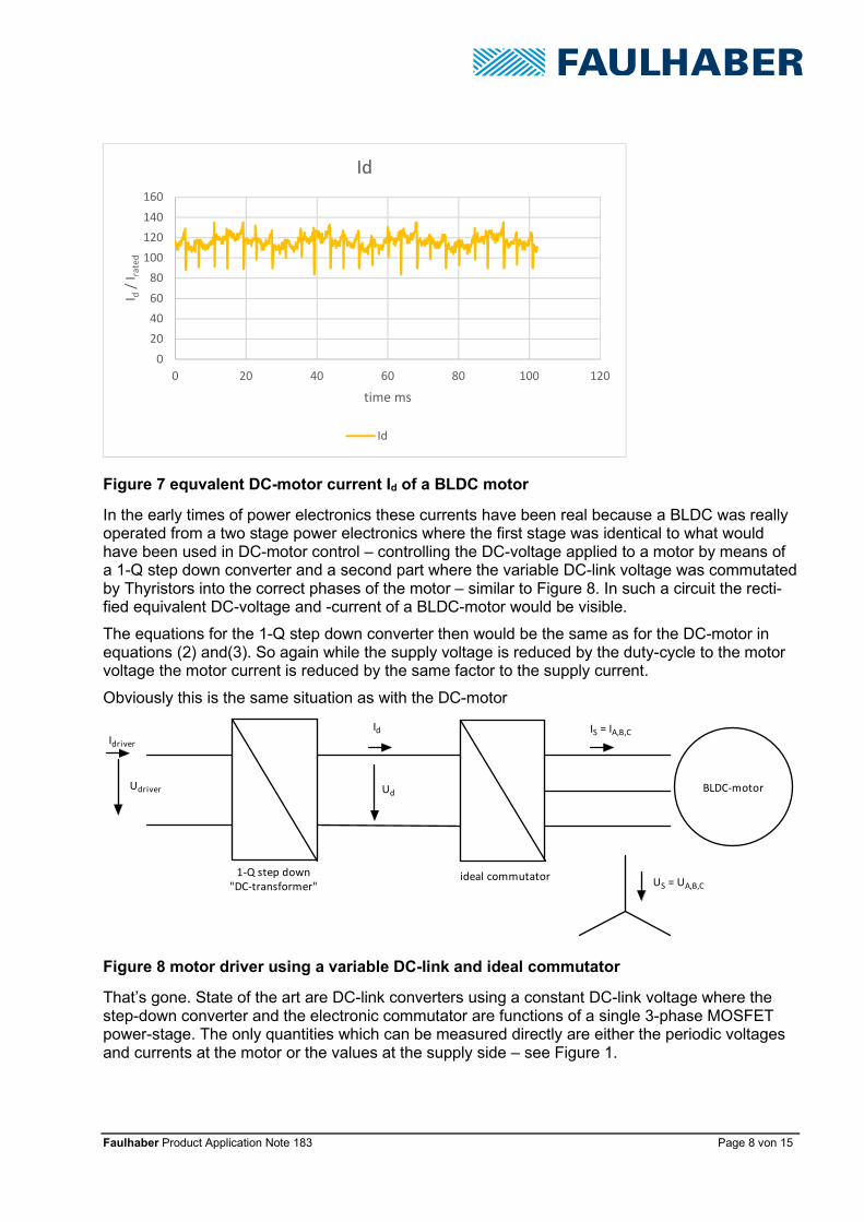
In the early times of power electronics these currents have been real because a BLDC was really operated from a two stage power electronics where the first stage was identical to what would have been used in DC-motor control – controlling the DC-voltage applied to a motor by means of a 1-Q step down converter and a second part where the variable DC-link voltage was commutated by Thyristors into the correct phases of the motor – similar to Figure 8. In such a circuit the recti-fied equivalent DC-voltage and -current of a BLDC-motor would be visible.
The equations for the 1-Q step down converter then would be the same as for the DC-motor in equations (2) and(3). So again while the supply voltage is reduced by the duty-cycle to the motor voltage the motor current is reduced by the same factor to the supply current.
Obviously this is the same situation as with the DC-motor
That’s gone. State of the art are DC-link converters using a constant DC-link voltage where the step-down converter and the electronic commutator are functions of a single 3-phase MOSFET power-stage. The only quantities which can be measured directly are either the periodic voltages and currents at the motor or the values at the supply side – see Figure 1.
0
20
40
60
80
100
120
140
160
0 20 40 60 80 100 120
I d/
I ra
ted
time ms
Id
Id
BLDC-motorUdriver
Idriver
US = UA,B,C
IS = IA,B,CId
Ud
1-Q step down
"DC-transformer"ideal commutator
Figure 7 equvalent DC-motor current Id of a BLDC motor
Figure 8 motor driver using a variable DC-link and ideal commutator
Faulhaber Product Application Note 183 Page 9 von 15
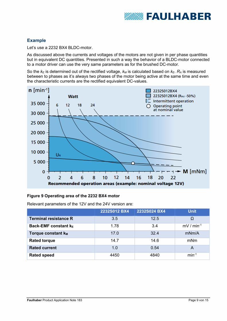
Example
Let’s use a 2232 BX4 BLDC-motor.
As discussed above the currents and voltages of the motors are not given in per phase quantities but in equivalent DC quantities. Presented in such a way the behavior of a BLDC-motor connected to a motor driver can use the very same parameters as for the brushed DC-motor.
So the kE is determined out of the rectified voltage, kM is calculated based on kE. RA is measured between to phases as it’s always two phases of the motor being active at the same time and even the characteristic currents are the rectified equivalent DC-values.
Relevant parameters of the 12V and the 24V version are:
2232S012 BX4 2232S024 BX4 Unit
Terminal resistance R 3.5 12.5 Ω
Back-EMF constant kE 1.78 3.4 mV / min-1
Torque constant kM 17.0 32.4 mNm/A
Rated torque 14.7 14.6 mNm
Rated current 1.0 0.54 A
Rated speed 4450 4840 min-1
Figure 9 Operating area of the 2232 BX4 motor

Faulhaber Product Application Note 183 Page 10 von 15
So if the motor would be conneted to a driver which is supplied with 24V and controls the motor at a speed of 3000 min-1 @ 10mNm the operating point would be:
2342S012 CR 2342S024 CR Unit
motor current: iA = T / kM 0.59 0.31 A
Back-EMF: ui = kE x n 5.34 10.18 V
motor voltage Us = RA iA + n kE 7.4 14.1 V
duty cycle d 30.8 58.6 %
Idriver 0.18 0.18 A
Again the motor voltage is controlled by the driver to fit equation (1) for both variants. The motor current for the 12V version is roughly twice the motor current of the 24V version but the current into the driver is the same in both situations. Obviously again at the supply side of the driver can’t protect the motor, the driver however can.
As the motor current is reduced by a variable factor depending on the actual
duty cycle, a motor used at different working points can’t be protected by a
fuse at the supply side of the driver which can be easily confirmed in the ex-
ample. A rated motor current of 1.0A for the 12V version results in:
Idriver = 146mA @ d=15% - holding at n=0
Idriver = 500mA @ d=50%
Idriver = 1000mA @ d=100%
FAULHABER SpeedControllers and MotionControllers measure the phase currents and calculate the equivalent DC-current of the motor. Any limiting paramters are expected in these quantities.
Faulhaber Product Application Note 183 Page 11 von 15
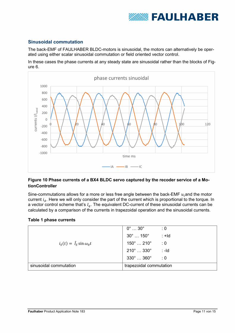
Sinusoidal commutation
The back-EMF of FAULHABER BLDC-motors is sinusoidal, the motors can alternatively be oper-ated using either scalar sinusoidal commutation or field oriented vector control.
In these cases the phase currents at any steady state are sinusoidal rather than the blocks of Fig-ure 6.
Sine-commutations allows for a more or less free angle between the back-EMF and the motor current . Here we will only consider the part of the current which is proportional to the torque. In a vector control scheme that’s .:. The equivalent DC-current of these sinusoidal currents can be calculated by a comparison of the currents in trapezoidal operation and the sinusoidal currents.
# = .; sin
0° … 30° : 0
30° … 150° : +Id
150° … 210° : 0
210° … 330° : -Id
330° … 360° : 0
sinusoidal commutation trapezoidal commutation
-1000
-800
-600
-400
-200
0
200
400
600
800
1000
0 20 40 60 80 100 120
curr
en
ts I
/Ira
ted
time ms
phase currents sinuoidal
IA IB IC
Figure 10 Phase currents of a BX4 BLDC servo captured by the recoder service of a Mo-
tionController
Table 1 phase currents

Faulhaber Product Application Note 183 Page 12 von 15
The currents can be considered to be equivalent, if the same torque is generated. As the back-EMF of the motors is sinusoidal too a Fourrier series can again be used to calculate the generated effective power.
In each of the phases the power at any time can be expressed as:
= . = < sin × > cos + sin #$
%&
Over a complete period of the signals only components having the same frequency as the back-EMF # = < sin contribute to the effective power. So the block-wise currents of the trape-zoidal commutation and the sinusoidal currents are considered equal if their fundamental compo-nents are equal.
The two currents generate the same torque if:
.( = 12√3 .; ≈ 0.91 .; ≈ 1.29 . (5)
.; = 2√31 .( ≈ 1.1 .( (6)
Here .;is the amplitude of the phase current, .is the effective (RMS) phase current and .(is the equivalent DC-current which also equals the amplitude of the trapezoidal phase currents (see Fig-ure 6).
So the equvivalent DC-current of the sinusoidal phase currents can be calculated from the ampli-tude of the phase currents multiplied by 0.91.
It is to be noted that the two different current shapes doen’t generate the same losses. Current losses are caused by the ohmic losses in the winding which are proportional to 8. The RMS of the two currents wave forms is to be taken into account in the ohmic case.
-1,5
-1
-0,5
0
0,5
1
1,5
0 50 100 150 200 250 300 350 400 450
angle °
phase currents
Sine Trapezoidal
Figure 11 comparison of sine and trapezoidal currents

Faulhaber Product Application Note 183 Page 13 von 15
Comparing two currents generating the same torque results in
.,@A,*44
.,*,*44=
.(B2 3C
.( √6 1C = 13 ≈ 1.05
Where here the subscript eff explicitly denotes the RMS values of the current waveforms.
Summary
The actual motor current can not be measured on the supply side of any driver, therefore a fuse cannot provide thermal motor protection. A properly configured driver however can.
In FAULHABER BLDC motor datasheets any current is not expressed in rms phase cur-rents, but in a DC-equivalent current Id. Same for the motor parameters kE or kM, ex-pressed in DC-equivalent too.
The DC-equivalent current Id equals the current amplitude of the phase currents when us-ing trapezoidal commutation.
This Id can be used to calculate the motor torque F = G.( To generate the same torque, sinusoidal currents will have about 10% plus in amplitude
compared to the block currents of trapezoidal commutation (Figure 11). Compared with sinusoidal currents, the block currents of trapezoidal commutation will gen-
erate additional 5% losses at the same torque
Differences in efficiency between trapezoidal commutation and sine commu-tations can hardly be observed in any application as there are in fact addi-tional losses due to encoder errors or finite sampling times.

Faulhaber Product Application Note 183 Page 14 von 15
Rechtliche Hinweise
Urheberrechte. Alle Rechte vorbehalten. Ohne vorherige ausdrückliche schriftliche Zustimmung der Dr. Fritz
Faulhaber & Co. KG darf diese Application Note oder Teile dieser unabhängig von dem Zweck insbesondere
nicht vervielfältigt, reproduziert, gespeichert (z.B. in einem Informationssystem) oder be- oder verarbeitet wer-
den.
Gewerbliche Schutzrechte. Mit der Veröffentlichung, Übergabe/Übersendung oder sonstigen Zur-Verfü-
gung-Stellung dieser Application Note werden weder ausdrücklich noch konkludent Rechte an gewerblichen
Schutzrechten, übertragen noch Nutzungsrechte oder sonstige Rechte an diesen eingeräumt. Dies gilt ins-
besondere für gewerbliche Schutzrechte, die mittelbar oder unmittelbar den beschriebenen Anwendungen
und/oder Funktionen dieser Application Note zugrunde liegen oder mit diesen in Zusammenhang stehen.
Kein Vertragsbestandteil; Unverbindlichkeit der Application Note. Die Application Note ist nicht Vertrags-
bestandteil von Verträgen, die die Dr. Fritz Faulhaber GmbH & Co. KG abschließt, und der Inhalt der Appli-
cation Note stellt auch keine Beschaffenheitsangabe für Vertragsprodukte dar, soweit in den jeweiligen Ver-
trägen nicht ausdrücklich etwas anderes vereinbart ist. Die Application Note beschreibt unverbindlich ein
mögliches Anwendungsbeispiel. Die Dr. Fritz Faulhaber GmbH & Co. KG übernimmt insbesondere keine
Gewährleistung oder Garantie dafür und steht auch insbesondere nicht dafür ein, dass die in der Application
Note illustrierten Abläufe und Funktionen stets wie beschrieben aus- und durchgeführt werden können und
dass die in der Application Note beschriebenen Abläufe und Funktionen in anderen Zusammenhängen und
Umgebungen ohne zusätzliche Tests oder Modifikationen mit demselben Ergebnis umgesetzt werden kön-
nen. Der Kunde und ein sonstiger Anwender müssen sich jeweils im Einzelfall vor Vertragsabschluss infor-
mieren, ob die Abläufe und Funktionen in ihrem Bereich anwendbar und umsetzbar sind.
Keine Haftung. Die Dr. Fritz Faulhaber GmbH & Co. KG weist darauf hin, dass aufgrund der Unverbindlich-
keit der Application Note keine Haftung für Schäden übernommen wird, die auf die Application Note und deren
Anwendung durch den Kunden oder sonstigen Anwender zurückgehen. Insbesondere können aus dieser
Application Note und deren Anwendung keine Ansprüche aufgrund von Verletzungen von Schutzrechten Drit-
ter, aufgrund von Mängeln oder sonstigen Problemen gegenüber der Dr. Fritz Faulhaber GmbH & Co. KG
hergeleitet werden.
Änderungen der Application Note. Änderungen der Application Note sind vorbehalten. Die jeweils aktuelle
Version dieser Application Note erhalten Sie von Dr. Fritz Faulhaber GmbH & Co. KG unter der Telefonnum-
mer +49 7031 638 688 oder per Mail von [email protected].
Legal notices
Copyrights. All rights reserved. This Application Note and parts thereof may in particular not be copied,
reproduced, saved (e.g. in an information system), altered or processed in any way irrespective of the purpose
without the express prior written consent of Dr. Fritz Faulhaber & Co. KG.
Industrial property rights. In publishing, handing over/dispatching or otherwise making available this Appli-
cation Note Dr. Fritz Faulhaber & Co. KG does not expressly or implicitly grant any rights in industrial property
rights nor does it transfer rights of use or other rights in such industrial property rights. This applies in particular
to industrial property rights on which the applications and/or functions of this Application Note are directly or
indirectly based or with which they are connected.

Faulhaber Product Application Note 183 Page 15 von 15
No part of contract; non-binding character of the Application Note. The Application Note is not a constit-
uent part of contracts concluded by Dr. Fritz Faulhaber & Co. KG and the content of the Application Note does
not constitute any contractual quality statement for products, unless expressly set out otherwise in the re-
spective contracts. The Application Note is a non-binding description of a possible application. In particular
Dr. Fritz Faulhaber & Co. KG does not warrant or guarantee and also makes no representation that the pro-
cesses and functions illustrated in the Application Note can always be executed and implemented as de-
scribed and that they can be used in other contexts and environments with the same result without additional
tests or modifications. The customer and any user must inform themselves in each case before concluding a
contract concerning a product whether the processes and functions are applicable and can be implemented
in their scope and environment.
No liability. Owing to the non-binding character of the Application Note Dr. Fritz Faulhaber & Co. KG will not
accept any liability for losses arising from its application by customers and other users. In particular, this
Application Note and its use cannot give rise to any claims based on infringements of industrial property rights
of third parties, due to defects or other problems as against Dr. Fritz Faulhaber GmbH & Co. KG.
Amendments to the Application Note. Dr. Fritz Faulhaber & Co. KG reserves the right to amend Application
Notes. The current version of this Application Note may be obtained from Dr. Fritz Faulhaber & Co. KG by
calling +49 7031 638 688 or sending an e-mail to [email protected].