Embed Size (px)
Citation preview

COMMISSION OF THE EUROPEAN COMMUNITIES
Equitable Testing and Evaluation of Marine Energy E xtraction Devices in terms of Performance, Cost and Environme ntal Impact
Grant agreement number: 213380
Deliverable D5.2 Device classification template
DRAFT

Grant Agreement number: 213380
Project acronym: EQUIMAR
Project title: Equitable Testing and Evaluation of Marine Energy Extraction Devices in terms of Performance, Cost and Environmental Impact
Deliverable D5.2
Device classification template
L.E. Myers, A.S. Bahaj University of Southampton
F. Gardner Team work Technology
C. Bittencourt, J. Flinn Det Norske Veritas
July 2009 Summary This document describes a process to classify wave and tidal energy conversion devices herein referred to as wave and tidal energy devices. The classification recommends a “layered” structure to describe various elements of a wave or tidal energy device.
The top layer includes information that will allow the user to verify the basic form of the device providing information on the method of energy extraction, and the characterisation of the physical form and motion paths of the hydrodynamic subsystem. Layer 2 offers information concerning the power take-off system, whilst layer 3 addresses how the device is kept in place in the marine environment and how key aspects of the device are controlled. The device classification template is designed to be compact in nature whilst conveying sufficient information to allow the form and function of the device to be quantified. It is expected to be of significant importance to funding and non-technical organisations.
The wave energy device section of this document (section 4) will be submitted in due course.

Institution
Logo
Institution
Logo

Workpackage 5 EquiMar D5.2
i
CONTENTS
1. INREODUCTION................................................................................................................................................................. 2 1.1 MOTIVATION FOR DEVICE CLASSIFICATION.......................................................................................................................... 2 1.2 OBJECTIVE AND SCOPE OF THIS REPORT............................................................................................................................... 2
2. METHODOLOGY................................................................................................................................................................ 3 2.1 SUBSYSTEMS OF WAVE AND TIDAL ENERGY DEVICES............................................................................................................... 3 2.2 DEVICE CLASSIFICATION LAYER DESCRIPTION.......................................................................................................................... 4
3. TIDAL ENERGY DEVICE CLASSIFICATION ................. ............................................................................................. 4 3.1 TIDAL ENERGY DETAILED DEVICE CLASSIFICATION.................................................................................................................. 4 3.2 TIDAL ENERGY BRIEF DEVICE CLASSIFICATION................................................................................................................... 3—1
4. WAVE ENERGY DEVICE CLASSIFICATION.................. ....................................................................................... 4—1

Workpackage 5 EquiMar D5.2
2
1. INTRODUCTION
1.1 MOTIVATION FOR DEVICE CLASSIFICATION This report falls under the auspices of “EquiMar”; Equitable Testing and Evaluation of Marine Energy Extraction Devices in terms of Performance, Cost and Environmental Impact. The EquiMar project is funded by the European Commission as part of its 7th Framework programme. It is a collaborative research and development project involving a consortium of 23 partners from 11 member states, representing nearly all aspects of the marine energy sector from universities and developers through to certification agencies. The need for a method to classify wave and tidal energy conversion devices is required through Deliverable 5.2 that falls under objective 1 of WP5:
1. Produce protocols for the classification of devices and the quantification of performance in the context of multi megawatt arrays or farms.
1.2 OBJECTIVE AND SCOPE OF THIS REPORT Wave and tidal energy conversion devices are at an early development stage with only a handful of prototype and commercial demonstrators deployed in the seas around the world. Present concepts and methods for extracting energy from the marine environment vary widely which has lead to an extensive range of device types, power take-off and mooring/anchoring requirements.
The overall aim of this document is to provide a classification template that will allow a user to characterise the basic form and function of the various sub-elements that make up the wave or tidal energy device. For wave and tidal technologies the device will be classified at several levels:
1. The uppermost level will give information regarding the basic functionality of the device. E.g. how it harnesses energy from the marine environment and converts this into motion that is more suitable for energy extraction.
2. The second level addresses the power take off sub system where mechanical work is converted into a more useful form of energy ready for conveyance to the shore.
3. The third level characterises the method in which the device ‘holds station’ or is fixed in position in the marine environment. This encompasses mooring/anchoring systems. Certain elements of control are also included in this layer.
This method of device classification will be of benefit to a variety of stakeholders. Funding bodies and organisations frequently have to assess novel devices with information gaps in the supplied data. This classification will allow them to identify the method of operation, device efficiency claims and compare it to similar existing devices.
It is the aim that the classification can be expanded to accommodate new novel devices. Whilst the levels and areas of characterisation will remain it will be possible to add new descriptors when appropriate to the classification. The device classification template does not include financial data or issues relating to installation and maintenance. For commercial demonstrator and first-generation devices these issues are likely to be highly variable with respect to distance along the device development path.
Workpackage 5 EquiMar D5.2
3
2. METHODOLOGY
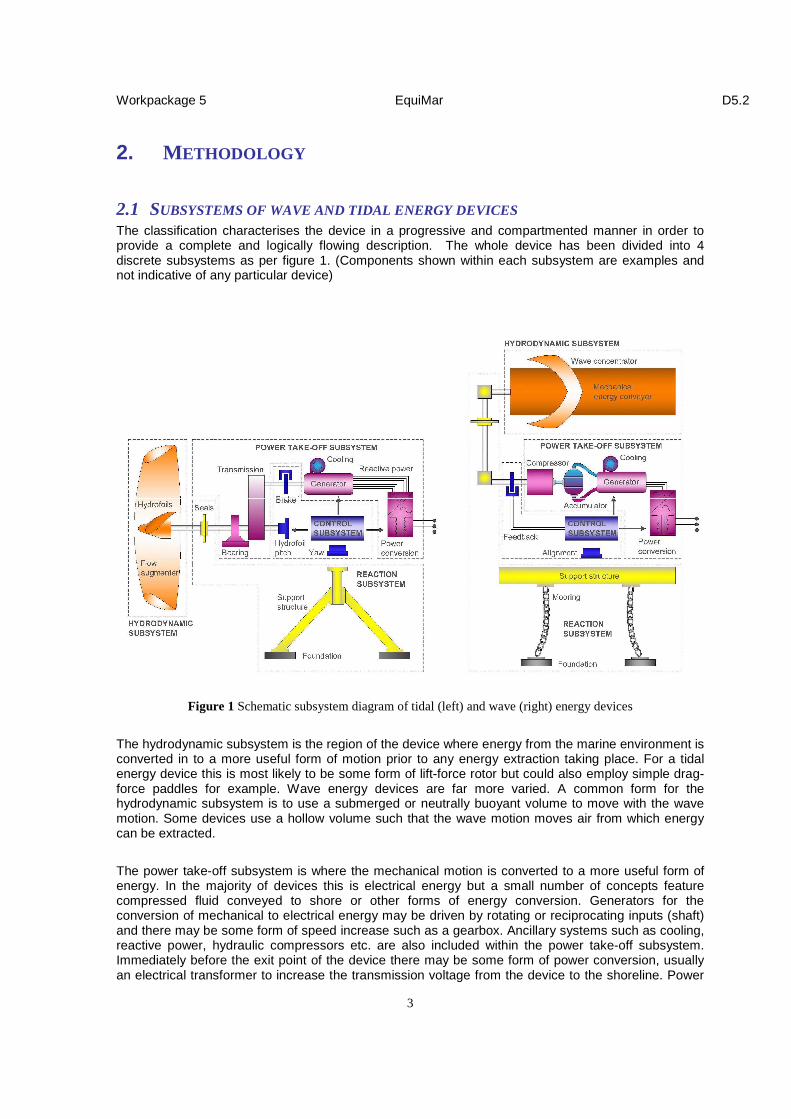
2.1 SUBSYSTEMS OF WAVE AND TIDAL ENERGY DEVICES The classification characterises the device in a progressive and compartmented manner in order to provide a complete and logically flowing description. The whole device has been divided into 4 discrete subsystems as per figure 1. (Components shown within each subsystem are examples and not indicative of any particular device)
Figure 1 Schematic subsystem diagram of tidal (left) and wave (right) energy devices
The hydrodynamic subsystem is the region of the device where energy from the marine environment is converted in to a more useful form of motion prior to any energy extraction taking place. For a tidal energy device this is most likely to be some form of lift-force rotor but could also employ simple drag-force paddles for example. Wave energy devices are far more varied. A common form for the hydrodynamic subsystem is to use a submerged or neutrally buoyant volume to move with the wave motion. Some devices use a hollow volume such that the wave motion moves air from which energy can be extracted.
The power take-off subsystem is where the mechanical motion is converted to a more useful form of energy. In the majority of devices this is electrical energy but a small number of concepts feature compressed fluid conveyed to shore or other forms of energy conversion. Generators for the conversion of mechanical to electrical energy may be driven by rotating or reciprocating inputs (shaft) and there may be some form of speed increase such as a gearbox. Ancillary systems such as cooling, reactive power, hydraulic compressors etc. are also included within the power take-off subsystem. Immediately before the exit point of the device there may be some form of power conversion, usually an electrical transformer to increase the transmission voltage from the device to the shoreline. Power

Workpackage 5 EquiMar D5.2
4
conditioning may also be included to ensure the electrical output from the device is of a suitable quality to be fed into the main electrical grid system.
The control subsystem encapsulates components used to control the device in terms of station-keeping, power capture from the marine environment and safety systems. For a tidal energy device this will include means to control rotor speeds and their alignment to the tidal flow. Control for a wave device may include strategies to optimise power capture from different sea states.
The reaction subsystem is composed of the device support structure and foundations. These aspects of the device ensure that it maintains its spatial position within the marine environment. There are several methods of anchoring or fixing the device to the seabed or shoreline including tubular piles, anchor chains and gravity foundations. The support structure may take almost any form dependant upon the device and the nature of its components.
2.2 DEVICE CLASSIFICATION LAYER DESCRIPTION
Layer 1 addresses the general form of the device. For both wave and tidal devices this is regarded as the characterisation/specification of the hydrodynamic subsystem. This system converts the wave/tidal motion into a more useful mechanical form suitable for extraction of power. The form and motion paths of this subsystem provide the most meaningful method of classifying the type of device.
Layer 2 addresses the power take off subsystem. Here, the converted mechanical motion from the hydrodynamic subsystem is converted into electrical power. There are a variety of different methods to generate electricity in terms of principle motion and operational speed. Often there is a gearbox or some means to increase the speed of motion between the hydrodynamic subsystem and the generator. Layer 2 also quantifies the ‘edge of device’ electrical power output allowing estimates of efficiency to be made by the user.
Layer 3 addresses the reaction and control subsystem, principally the method of keeping the device ‘at station’ in the water and characterising how the hydrodynamic subsystem is aligned to the waves/tidal current.
Due to the large differences between wave and tidal energy devices (principally for the hydrodynamic and power take-off subsystems) each has been addressed with a separate classification template.
3. TIDAL ENERGY DEVICE CLASSIFICATION
In all layer descriptions a category of NOT APPLICABLE can be applied if the predetermined categories do not apply to the device that is being characterised.
Descriptor to be used in classification
N/A
3.1 TIDAL ENERGY DETAILED DEVICE CLASSIFICATION
Layer 1 – Overarching device description

Workpackage 5 EquiMar D5.2
5
1.1 Description – Primary method of energy conversi on used in hydrodynamic subsystem Lift force rotor (LIFT) works in much the same way as that of a wind turbine or aircraft wing. The blade shape causes a pressure difference across its surface as fluid flows over it. By creating high and low pressure regions the blade or lifting structure moves towards the low pressure region.
Drag force (DRAG) structures rely on the momentum of the fluid flow to push on the element forcing it in a certain direction.
Venturi (VENTURI) devices use a tapered tube-like structure to accelerate the fluid flow. This faster moving flow is used to move air above the water surface and energy is extracted from this as opposed to the water. Thus the energy from the tidal stream is extracted indirectly. Descriptors
LIFT
DRAG
VENTURI
LIFT DRAG VENTURI
1.2 Description – Principal motion of hydrodynamic subsystem
A linear oscillating (LIN-OSC) system encompasses a component that moves back and forwards in the water, sweeping a rectangular area and extracting energy from the flow. The most common form is a hydrofoil blade working on the LIFT phenomenon detailed in the previous level.
A rotational (ROT) system encompasses a hydrodynamic subsystem that rotates about a fixed axis.
A linear (LIN) system moves in one direction. In the case of tidal energy sytems this has been defined as moving in a linear direction for each tidal cycle direction. In most cases during a tidal cycle (lasting approximately 12 hours) the flow changes direction once flowing ‘in’ and ‘out’ of a site.
Descriptors
LINEAR-OSC
ROTATION
LINEAR
Workpackage 5 EquiMar D5.2
6
LINEAR OSCILLATING ROTATION LINEAR
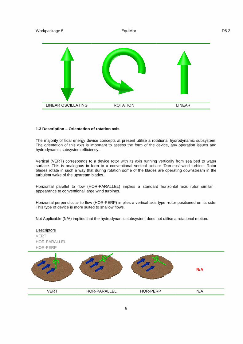
1.3 Description – Orientation of rotation axis
The majority of tidal energy device concepts at present utilise a rotational hydrodynamic subsystem. The orientation of this axis is important to assess the form of the device, any operation issues and hydrodynamic subsystem efficiency.
Vertical (VERT) corresponds to a device rotor with its axis running vertically from sea bed to water surface. This is analogous in form to a conventional vertical axis or ‘Darrieus’ wind turbine. Rotor blades rotate in such a way that during rotation some of the blades are operating downstream in the turbulent wake of the upstream blades.
Horizontal parallel to flow (HOR-PARALLEL) implies a standard horizontal axis rotor similar I appearance to conventional large wind turbines.
Horizontal perpendicular to flow (HOR-PERP) implies a vertical axis type -rotor positioned on its side. This type of device is more suited to shallow flows.
Not Applicable (N/A) implies that the hydrodynamic subsystem does not utilise a rotational motion.
Descriptors
VERT
HOR-PARALLEL
HOR-PERP
N/A
VERT HOR-PARALLEL HOR-PERP N/A

Workpackage 5 EquiMar D5.2
7
1.4 Description - Number of hydrodynamic subsystems per device
This level description quantifies the number of hydrodynamic subsystems per device. To be counted each hydrodynamic subsystem should have a separate drive train. The descriptor for this level is simply a number corresponding to the description above.
Descriptors
Numerical value
1 2 3
1.5 Description – Number of lift or drag elements p er hydrodynamic subsystem
This level description defines the number of lift and/or drag elements for each hydrodynamic subsystems. Most commonly the elements are referred to as ‘blades’. The number of blades can influence the rotational speed, efficiency of energy capture and cost of the device. For a Venturi type device (see 1.1) N/A should be entered as a value for this descriptor.
Descriptors
Numerical value
1.6 Description – Incorporation of free stream velo city augmentation
This level description provides information as to whether the undisturbed FREE stream flow is AUGMENTED (accelerated) onto the swept area of the hydrodynamic subsystem. For the purpose of this device classification the definition of an augmentation structure is:
A structure that alters the flow (in a beneficial manner) over the cross-sectional area occupied by the hydrodynamic subsystem from that which existed a short distance upstream of the device.
Thus augmentation can be via a full duct (as shown) or via guiding surfaces, a ramp-like structure mounted on the sea bed etc. This descriptor is important for the quantification of device efficiency. It can be combined with information provided in layer 3 to assess the effect of any flow augmentation.
Descriptors

Workpackage 5 EquiMar D5.2
8
AUGMENTED
FREE
AUGMENTED AUGMENTED FREE
1.7 Description - Capture area of hydrodynamic subs ystem(s)
This is defined by the extents of the area of the tidal stream intercepted or swept by the hydrodynamic subsystem(s) of the device. It does encompass any area associated with structures designed to augment the tidal stream as the extents of any augmentation structure may not be easily defined. The submitted value is the area expressed in square meters (m2).
Descriptors
Numerical value, units of m2
100 100 300

Workpackage 5 EquiMar D5.2
9
Layer 2 – Specification of Power take off 2.1 Description – Rated electrical power of device
This is the rated power output of the device as designated by the device developer. It is also referred to as the ‘nameplate’ or ‘nominal’ output. The location of this rating is at the exit of the individual device thus losses within an array of devices due to electrical conversion and/or conveyance to shore is not included. The figure quoted must be in Kilo Watts (kW) electrical. The N/A designation is applicable for devices not generating electrical power at the exit of the device.
Descriptors
Numerical value, units of kW
2.2 Description – Rated flow speed (m/s)
This is the flow speed at the centre of the capture area corresponding to the device rated power as defined in 2.1. Information given in 1.5, 1.6, 2.1 and 2.2 are essential for assessment of device capture efficiency and the suitability for installation at different tidal energy sites.
Descriptors
Numerical value, units of ms-1
2.3 Description – Generator type
In the overwhelming majority of devices mechanical motion will be converted to electricity via a generator. 2.3 defines the type of generator that is utilised within the device.
Singly-fed asynchronous generators (S-F ASYNCH) are commonly represented by the squirrel cage generator. This is fixed to frequency speed generator with a single set of electrical winding within which a magnetic field is induced via the feeding in of electrical energy. There is a limited amount of speed control that can be applied, typically ±1% of the rated generator rotational speed.
Singly-fed synchronous generators (S-F SYNCH) operate in a similar manner mechanically rotating a permanent magnet assembly. A common form is the brushless DC permanent magnet generator.
A doubly-fed generator uses two sets of windings feeding power back into the generator. The principle advantage is reduced costs and a good degree of speed variation compared to asynchronous generators. Typically rotational speeds can vary up to ±30% of the nominal synchronous speed. They are available in both asynchronous (D-F ASYNCH) and synchronous (D-F SYNCH) versions as above.
With a linear generator (LINEAR) the stator is not circular so there is no rotation involved but the motion is one that reciprocates in a linear fashion.
Descriptors

Workpackage 5 EquiMar D5.2
10
S-F ASYNCH
S-F SYNCH
D-F ASYNCH D-F SYNCH
LINEAR
2.4 Description – Gearbox/differential specificatio n
This defines any fixed ratio increase in mechanical speed between the generator and the mechanical motion from the hydrodynamic subsystem. In the majority of cases both sets of motion will be rotational. If the motion paths are not the same then any mechanical advantage (lever) ratio should be specified. Hydraulic fluid can also be used to provide power transmission and this is also included in this descriptor.
Descriptors First part - second part
GEARBOX - Enter ratio of output to input speeds. X:X
LEVER
HYDRAULIC
For example, a mechanical gearbox (1 rotor revolution = 10 generator revolutions) would be defined as: GEARBOX - 10:1
2.5 Description – Electrical/energy conversion and output
This description defines the characteristics of any electrical conversion carried out between the generator and the exit of the device.
The first part of the descriptor details the input to the power conversion from the generator or similar. This can be DC electricity (DC) AC electricity (AC) or some from of pressurised hydraulic fluid (HYD). The second part describes the type of output from the power conversion. The third part of the descriptor defines the electrical voltage output from the tidal energy device in kV. There is also the option to specify other outputs such as pressurised hydraulic fluid although it is accepted that the vast majority of tidal energy devices will output electricity at the edge of the device.
Descriptors
First part - second part - third part
DC - DC Enter electrical output in kV
AC - AC HYD
HYD - HYD
Example outputs:
DC - AC - 33kV
AC - AC - 33kV
HYD - AC - 11kV
DC - HYD - HYD

Workpackage 5 EquiMar D5.2
11
Layer 3 – Specification of reaction and control sub systems
3.1 Description - Basic form of foundation/anchor
3.1 describes how the device is anchored to the sea bed. A single category has been included should shoreline anchoring be possible but in the vast majority of cases the tidal energy device will be ultimately secured to the sea bed using a variety of interface methods described below.
A pile foundation is most commonly a hollow cylindrical structure that is drilled / impacted into the seabed to enable the tidal stream energy converter to hold station in the flow. Any overturning motion is resisted via the length of embedded pile and the friction between the pile casing and the sea bed material. Pile foundation can consist of a single pile (MONOPILE) or several often smaller multiple piles (MULTI-PILE).
A Gravity base (GRAVITY BASE) is a large mass deployed at the base of the structure. The force of the base is calculated to be sufficient to resist any overturning moment applied to the structure via the tidal stream and/or any additional forces.
An anchor foundation can utilise a variety of methods to provide a fixing to the seabed. For the purpose of this classification all anchors are defined as being sea bed piercing. Typical examples include claw-type anchors that are dragged into the bed material and screw anchors which as the name suggests are screwed into the sea bed. Tidal energy devices can be attached to the sea bed by single (SINGLE-POINT ANCHOR) or multiple anchors (MULTI-POINT ANCHOR).
A device may be suspended beneath a buoyant pontoon (PONTOON). In this case the pontoon will need to be held in position typically via a gravity base or sea bed anchor foundations. In this case more than one foundation/support descriptor should be specified.
Descriptors
MONOPILE
MULTI-PILE
SINGLE-POINT ANCHOR
MULTI-POINT ANCHOR
GRAVITY BASE
PONTOON

Workpackage 5 EquiMar D5.2
12
MONOPILE GRAVITY BASE MULTI-POINT ANCHOR
MULTI-PILE SINGLE-POINT ANCHOR PONTOON
3.2 Description – Working water depth range of devi ce
3.2 will enable the user of the device classification to assess clearances between the hydrodynamic subsystem and the sea bed / water surface. It will also have implications for installation and maintenance. The description should specify the working water depth of the device in meters, the first part is the minimum working depth and the second part is the maximum working depth.
Descriptors
First part (minimum depth) - second part
Enter numerical value, -Enter numerical value,
units of m units of m
Example outputs:
30 - 35m
3.3 Description – Alignment mechanism for hydrodyna mic subsystem
This describes both the inclusion of and the operation of any mechanism used to align the hydrodynamic subsystem to the incoming flow. The first part of the description confirms whether an alignment mechanism for the hydrodynamic subsystem is present (YES/NO) whilst the second part defines whether it is an ACTIVE or PASSIVE system. An active system will utilise a mechanical reaction to the tidal environment in order to align the hydrodynamic subsystem at the optimum orientation to the tidal flow. A Passive system will utilise external forces (those of the tidal environment) to alter the alignment. The type of system has implications for device complexity, efficiency of energy conversion, structural loading and cost.

Workpackage 5 EquiMar D5.2
13
Descriptors
First part - second part
YES - ACTIVE
NO - PASSIVE
Example outputs:
YES – ACTIVE
NO - N/A
YES - PASSIVE
3.4 Description – Power regulation
This describes the form (if any) used to regulate energy extracted from the tidal stream flow. It is likely that nearly all tidal energy devices will regulate extracted power as peak forces will be strong in tidal sites. The method employed for power regulation has implications upon system reliability and cost. For the majority of devices power regulation will be employed at the point of energy conversion within the hydrodynamic subsystem e.g. blades.
Descriptors
First part - second part
YES - ACTIVE
NO - PASSIVE
Example outputs:
YES – ACTIVE
NO - N/A
YES - PASSIVE

Workpackage 5 EquiMar D5.2
3—1
3.2 TIDAL ENERGY BRIEF DEVICE
CLASSIFICATION
Layer 1 – Overarching device description 1.1 Description – Primary method of energy conversion used in hydrodynamic subsystem
Descriptors Submitted value
LIFT
DRAG
VENTURI
1.2 Description – Principal motion of hydrodynamic subsystem
Descriptors Submitted value
LINEAR-OSC
ROTATION
LINEAR
1.3 Description – Orientation of rotation axis
Descriptors Submitted value
VERT
HOR-PARALLEL
HOR-PERP
1.4 Description – Number of hydrodynamic subsystems per device
Descriptors Submitted value
Enter numeric value
1.5 Description – Number of lift or drag elements per hydrodynamic subsystem
Descriptors Submitted value
Enter numeric value
1.6 Description – Incorporation of free stream velocity augmentation?
Descriptors Submitted value
FREE
AUGMENTED
1.7 Description – Capture area of hydrodynamic subsystem(s)
Descriptors Submitted value
Enter numeric value. Units of m2
Layer 2 – Specification of Power take off 2.1 Description – Rated electrical power of device
Descriptors Submitted value
Enter numeric value. Units of MW
2.2 Description – Rated flow speed
Descriptors Submitted value
Enter numeric value. Units of ms-1
2.3 Description – Generator type
Descriptors Submitted value
S-F ASYNCH
S-F SYNCH
D-F ASYNCH
D-F SYNCH
LINEAR
2.4 Description – Gearbox/differential specification
Descriptors
First part - Second part
GEARBOX
LEVER
HYDRAULIC
-
Enter ratio of output to input speeds. X:X
Submitted value
-
2.5 Description – electrical/energy conversion and output
Descriptors
INPUT - OUTPUT 1 - OUTPUT 2
DC DC
AC AC
Value of elec. output in kV
HYD
-
HYD
-
HYD Submitted value
- -

Workpackage 5 EquiMar D5.2
3—2
Layer 3 – Specification of reaction and control sub systems
3.1 Description - Basic form of foundation/anchor
Descriptors Submitted value(s)
MONOPILE
MULTI-PILE
SINGLE-POINT ANCHOR
MULTI-POINT ANCHOR
GRAVITY BASE
PONTOON
3.2 Description – Working water depth range of device
Descriptors
Minimum depth - Maximum depth
Enter numerical value. Units of (m)
- Enter numerical value. Units of (m)
Submitted value
-
3.3 Description – Alignment mechanism for hydrodynamic subsystem
Descriptors
First part - Second part
YES ACTIVE
NO -
PASSIVE Submitted value
-
3.4 Description – Power regulation
Descriptors
First part - Second part
YES ACTIVE
NO -
PASSIVE Submitted value
-

Workpackage 5 EquiMar D5.2
4—1
4. WAVE ENERGY DEVICE CLASSIFICATION To be populated