Embed Size (px)
Citation preview

EPS 6000 150 to 750 kVAUninterruptiblePower System
User’s Guide

IMPORTANT SAFETY INSTRUCTIONSAVE THESE INSTRUCTIONS — This manual contains important instructions for EPS 6000inverters that must be followed during installation, operation and maintenance of theequipment.
This equipment generates, uses, and can radiate radio frequency energy and, i f not instal led and used in accordance with instruction manual, may c a u s e h a r m f u l i n t e r f e r e n c e t o r a d i o communications. Operation of this equipment in a res ident ia l a rea is l ike ly to cause harmfu l interference in which case the user wil l be required to correct the interference at his own expense.
NOTE
As standards, speci f icat ions, and designs are subject to change, please ask for confirmation of the information given in t ihs publicaion.
This manual is a controlled document, pages should not individually be removed from this binder.
WARNING
OPENING ENCLOSURES EXPOSES HAZARDOUS VOLTAGES. ALWAYS REFER SERVICE TO QUALIFIED PERSONEL ONLY
WARNING
For service call1-800-438-7373
86-130033-00 B00 11/96Copyright © 1996 MGE UPS Systems, Inc.. All rightsreserved. Printed in U.S.A.
MGE UPS Systems1660 Scenic AvenueCosta Mesa, CA 92626(714) 557-1636
prepared for:
EPS 6000 150 to 750 kVA
Uninterruptible Power System
User’s Guide

WarrantySeller warrants to the Ultimate Purchaser (the purchaser who buys for use, and not for resale) that all products
furnished under this order and which are manufactured by Seller will conform to final specifications, drawings, samplesand other written descriptions approved in writing by Seller, and will be free from defects in materials and workmanship.These warranties shall remain in effect for period of twelve (12) months after delivery to the Ultimate Purchaser. But if theSeller installs the equipment or supplies technical direction of installation by contract, said one year shall run from thecompletion of installation, provided installation is not unreasonably delayed by Ultimate Purchaser. Parts replaced orrepaired in the warrant period shall carry the unexpired portion of the original warranty. A unit placed with the Purchaseron consignment and then later purchased will be warranted for twelve (12) months from the time the Seller receives notifi-cation of the Purchaser’s intent to purchase said consigned item. The foregoing in its entirety is subject to the provisionthat in no case will the total warranty period extend beyond 18 months from date Seller ships equipment from point ofmanufacture.
The liability of Seller hereunder is limited to replacing or repairing at Seller’s factory or on the job site at Seller’soption, any part or parts which have been returned to the Seller and which are defective or do not conform to such speci-fications, drawings or other written descriptions; provided that such part or parts are returned by the Ultimate Purchaserwithin ninety (90) days after such defect is discovered. The Seller shall have the sole right to determine if the parts are tobe repaired at the job site or whether they are to be returned to the factory for repair or replacement. All items returned toSeller for repair or replacement must be sent freight prepaid to its factory. Purchaser must obtain Seller’s Return GoodsAuthorization prior to returning items. The above conditions must be met if warranty is to be valid. Seller will not be liablefor any damage done by unauthorized repair work, unauthorized replacement parts, from any misapplication of the item,or for damage due to accident, abuse, or Act of God.
In no event shall the Seller be liable for loss, damage, or expense directly or indirectly arising from the use of theunits, or from any other cause, except as expressly stated in this warranty. Seller makes no warranties, express orimplied, including any warranty as to merchantability or fitness for a particular purpose or use. Seller is not liable for andPurchaser waives any right of action it has or may have against Seller for any consequential or special damages arisingout of any breach of warranty, and for any damages Purchaser may claim for damage to any property or injury or death toany person arising out of its purchase of the use, operation or maintenance of the product. Seller will not be liable for anylabor subcontracted or performed by Purchaser for preparation of warranted item for return to Seller’s factory or forpreparation work for field repair or replacement. Invoicing of Seller for labor either performed or subcontracted byPurchaser will not be considered as a liability by the Seller.
This warranty shall be exclusive of any and all other warranties express or implied and may be modified only by awriting signed by an officer of the Seller. This warranty shall extend to the Ultimate Purchaser but to no one else.Accessories supplied by Seller, but manufactured by others, carry any warranty the manufacturers have made to Sellerand which can be passed on to Ultimate Purchaser.
Seller makes no warranty with respect to whether the products sold hereunder infringe any patent, U.S. or foreign,and Buyer represents that any specially ordered products do not infringe any patent. Buyer agrees to indemnify and holdSeller harmless from any liability by virtue of any patent claims where Buyer has ordered a product conforming to Buyer’sspecifications, or conforming to Buyer’s specific design.
Buyer has not relied and shall not rely on any oral representation regarding the Product sold hereunder and any oralrepresentation shall not bind Seller and shall not be part of any warranty.
There are no warranties which extend beyond the description on the face hereof. In no event shall MGE UPSSystems, Inc. be responsible for consequential damages or for any damages except as expressly stated herein.
Service and Factory Repair - Call 1 - 800 - 438 - 7373Direct questions about the operation, repair, or servicing of this equipment to MGE UPS Systems, Inc. Customer
Support Services. Include the part number, assembly number, and serial number of the unit in any correspondence.Should you require factory service for your equipment, contact MGE UPS Systems, Inc. Customer Support Services andobtain a Return Goods Authorization (RGA) prior to shipping your unit. Never ship equipment to MGE UPS Systems, Inc.without first obtaining an RGA.
Proprietary Rights StatementThe information in this manual is the property of MGE UPS Systems, Inc., and represents a proprietary article in
which MGE UPS Systems, Inc., retains any and all patent rights, including exclusive rights of use and/or manufactureand/or sale. Possession of this information does not convey any permission to reproduce, print, or manufacture the articleor articles shown herein. Such permission may be granted only by specific written authorization, signed by an officer ofMGE UPS Systems, Inc.
IBM, PC-AT, ES/9000, and AS/400 are trademarks of International Business Machines Corporation. MGE and MGEUPS Systems are trademarks of MGE UPS Systems, Inc. Other trademarks that may be used herein are owned by theirrespective companies and are referred to in an editorial fashion only.
Revision HistoryEPS 6000 Uninterruptible Power System Installation Manual86-130033-00 Copyright © 1996 MGE UPS Systems. All rights reserved. Printed in U.S.A.Revision: B00 11/96
EPS 6000 150 to 750 kVAUninterruptible Power System
User’s Guide

Section I Introductionsection description page number1.0 . . . . . . . . . . . . . . . Scope 1 — 11.1 . . . . . . . . . . . . . . . General Description 1 — 11.2 . . . . . . . . . . . . . . . Description of UPS Module
Major Internal Components 1 — 61.2.1 Rectifier/Battery Charger 1 — 61.2.2 Inverter 1 — 61.2.3 Inverter Transformer 1 — 61.2.4 Static Switch 1 — 61.2.5 Battery System 1 — 6
1.3 . . . . . . . . . . . . . . . Options 1 — 141.4 . . . . . . . . . . . . . . . Specifications, UPS Modules 1 — 16
1.4.1 Electrical 1 — 161.4.2 Mechanical 1 — 171.4.3 Environmental 1 — 17
Section II Operation2.0 . . . . . . . . . . . . . . . Scope 2 — 12.1 . . . . . . . . . . . . . . . System Operation Overview 2 — 1
2.1.1 Normal Operation 2 — 12.1.2 On-Battery Operation 2 — 1
2.2 . . . . . . . . . . . . . . . Indicators and Controls 2 — 22.2.1 Front Panel 2 — 32.2.2 Alphanumeric Display
and Controls 2 — 52.2.3 Hidden Panel 2 — 82.2.4 Circuit Breakers
and Contactors 2 — 112.3 . . . . . . . . . . . . . . . Using the
Alphanumeric Display 2 — 192.3.1 Settings 2 — 202.3.2 Alarms 2 — 212.3.3 Measurements 2 — 222.3.3.1 Voltage Measurements 2 — 232.3.3.2 Current Measurements 2 — 242.3.3.3 Power and
Frequency Measurements 2 — 252.3.3.4 Battery Measurements 2 — 26
iii
Contents
section description page number2.4 . . . . . . . . . . . . . . . Normal Operating Procedures 2 — 26
2.4.1 Checks Before Start-up 2 — 262.4.2 Start-up 2 — 272.4.3 Checks After Start-up 2 — 282.4.4 Shut-down 2 — 282.4.4.1 Emergency Shut-down
Using EPO 2 — 282.4.4.2 Normal Shut-down 2 — 292.4.5 Isolation for Maintenance 2 — 292.4.5.1 Without Maintenance Bypass 2 — 292.4.5.2 With Maintenance Bypass 2 — 302.4.6 Forced Transfers 2 — 312.4.6.1 Uninterrupted Transfer
Conditions 2 — 312.4.6.2 Forced Transfer From
Bypass AC Input Source to Inverter 2 — 31
2.4.6.3 Forced Transfer From Inverter to Bypass AC Input 2 — 31
2.5 . . . . . . . . . . . . . . . LCD Messages 2 — 32
Section III Maintenance and Service3.0 . . . . . . . . . . . . . . . Scope 3 — 13.1 . . . . . . . . . . . . . . . Safety Instructions 3 — 13.2 . . . . . . . . . . . . . . . Preventive Maintenance 3 — 13.3 . . . . . . . . . . . . . . . Replacement Parts 3 — 23.4 . . . . . . . . . . . . . . . Troubleshooting and
MGE Servicing 3 — 2
Glossary . . . . . . . . . . . . . . . . . . . . . . . . . . . . . . . . . . . . . . . . . . g — 1
iv Contents
EPS 6000 150 to 750 kVA Uninterruptible Power System

Illustrationsfigure description page number1-1 . . . . . . . . . . . . . . . EPS 6000 UPS
150 - 375 kVA Pictorial 1 — 31-2 . . . . . . . . . . . . . . . Typical Single-line Diagram:
EPS 6000 480 VAC Input/Output Single-Module 225 kVA UPS With Battery Cabinet 1 — 3
1-3 . . . . . . . . . . . . . . . EPS 6000 UPS 500 kVA Pictorial 1 — 4
1-4 . . . . . . . . . . . . . . . Typical Single-Line Diagram:EPS 6000 480 VAC Input/Output Single Module 500 kVA UPS With Battery Cabinet 1 — 4
1-5 . . . . . . . . . . . . . . . EPS 6000 UPS 750 kVA Pictorial 1 — 5
1-6 . . . . . . . . . . . . . . . Typical Single-Line Diagram:EPS 6000 480 VAC Input/Output Single Module 750 kVA UPS With Battery Cabinet 1 — 5
1-7 . . . . . . . . . . . . . . . EPS 6000 Major Internal Components, Single-Module UPS 150 - 225 kVA 1 — 7
1-8 . . . . . . . . . . . . . . . EPS 6000 Major Internal Components, Single-Module UPS 300/375 kVA 1 — 8
1-9 . . . . . . . . . . . . . . . EPS 6000 Major Internal Components 500kVA UPS Cabinet 1 — 9
1-10 . . . . . . . . . . . . . . EPS 6000 Major Internal Components 500 kVA Input/Output Cabinet 1 — 10
1-11 . . . . . . . . . . . . . . EPS 6000 Major Internal Components 750 kVA UPS Cabinet 1 1 — 11
1-12 . . . . . . . . . . . . . . EPS 6000 Major Internal Components 750 kVA UPS Cabinet 2 1 — 12
1-13 . . . . . . . . . . . . . . EPS 6000 Major Internal Components 750 kVA UPS Cabinet 3 1 — 13
2-1 . . . . . . . . . . . . . . . Power Flow, Normal Operation 2 — 12-2 . . . . . . . . . . . . . . . Power Flow,
On-battery Operation 2 — 22-3 . . . . . . . . . . . . . . . Power Flow, Bypass Operation 2 — 22-4 . . . . . . . . . . . . . . . EPS 6000
Controls and Indicators 2 — 3
vContents
User’s guide

figure description page number2-5 . . . . . . . . . . . . . . . EPS 6000 Front Panel 2 — 32-6 . . . . . . . . . . . . . . . Alphanumeric
Display and Controls 2 — 62-7 . . . . . . . . . . . . . . . Hidden Panel 2 — 82-8 . . . . . . . . . . . . . . . EPS 6000
Major Internal Components, Single-Module UPS 150 - 225 kVA 2 — 12
2-9 . . . . . . . . . . . . . . . EPS 6000 Major Internal Components, Single-Module UPS 300/375 kVA 2 — 13
2-10 . . . . . . . . . . . . . . Single EPS 6000 500 kVA Major Internal Components UPS Cabinet 2 — 14
2-11 . . . . . . . . . . . . . . Single EPS 6000 500 kVA Major Internal Components Input/Output Cabinet 2 — 15
2-12 . . . . . . . . . . . . . . Single EPS 6000 500 kVA Major Internal Components UPS Cabinet 1 2 — 16
2-13 . . . . . . . . . . . . . . Single EPS 6000 500 kVA Major Internal Components UPS Cabinet 2 2 — 17
2-14 . . . . . . . . . . . . . . Single EPS 6000 500 kVA Major Internal Components UPS Cabinet 3 2 — 18
2-15 . . . . . . . . . . . . . . Location of Circuit Breakers and Switches Within the Electrical Path of the UPS Cabinet 2 — 19
2-16 . . . . . . . . . . . . . . Alphanumeric Display 2 — 192-17 . . . . . . . . . . . . . . General Display Configuration 2 — 202-18 . . . . . . . . . . . . . . Display Settings Display 2 — 212-19 . . . . . . . . . . . . . . Displaying Alarm Messages 2 — 222-20 . . . . . . . . . . . . . . Location of Sensors
Within the EPS 6000 UPS 2 — 222-21 . . . . . . . . . . . . . . Voltage Measurements 2 — 232-22 . . . . . . . . . . . . . . Current Measurements 2 — 242-23 . . . . . . . . . . . . . . Power and Frequency
Measurements 2 — 252-24 . . . . . . . . . . . . . . Battery Measurements 2 — 26
Tablestable description page number1-1 . . . . . . . . . . . . . . . EPS 6000 Model Numbers,
Single-Module UPS Modules 1 — 2
vi Contents
EPS 6000 150 to 750 kVA Uninterruptible Power System

This manual is designed for ease of use and easy locationof information.
To quickly find the meaning of terms used within the text, look in the Glossary.
This manual uses Noteboxes to convey important information. Noteboxes come in fourvarieties:
A WARNING notebox indicates informat ion provided to protect the user and ser v ice personnel against safety hazards and/or possible equipment damage
WARNINGA C AU T I O N n o t e b ox i n d i c a t e s i n fo r m a t i o n prov ided to p ro tec t the u s e r a n d s e r v i c e p e r s o n n e l a g a i n s t p o s s i b l e e q u i p m e n t damage.
CAUTION
An IMPORTANT notebox indicates informat ion provided as an operating instruction, or as an operating tip.
IMPORTANTA N OT E n o t e b ox i n d i c a t e s i n fo r m a t i o n p r o v i d e d a s a n o p e ra t i n g t i p o r a n equ ipment fea ture.
NOTE
How to use this manual
vii
User’s guide

(this page left blank intentionally)
EPS 6000 150 to 750 kVA Uninterruptible Power System

This manual provides technical information required foroperation and maintenance of the single EPS 6000 uninter-
ruptible power system (UPS). Please read this manual before operating the EPS 6000equipment. Please retain this manual for future reference.
The manual is divided into three sections:
Section I — General DescriptionThis section introduces the EPS 6000 family of uninterruptible power systems, including ageneral description of the system and its internal components, a description of availableoptions, and system specifications.
Section II — OperationThis section describes operating information for EPS 6000 UPS single-module systems,including an overview of the system, its components, and their functions; a description ofthe indicators and controls and their functions; and operational sequences to be followedfor all conditions of normal, emergency, and maintenance operation.
Section III — Maintenance and ServiceThis section describes maintenance of the EPS 6000 UPS, including safety instructions,preventive maintenance, information about replacement parts, and customer service.
A Glossary in the rear of this manual provides definitions of terms used within the text. Aseparate manual, the EPS 6000 UPS Installation Manual, (MGE part number 86-130035-00)provides detailed installation instructions.
EPS 6000 is a family of compact, high-efficiency uninter-ruptible power systems, available in power ratings for
single-module systems from 150 to 500 kVA. EPS 6000 UPS are optimized for compatibilitywith non-linear computer-type loads. Computer-aided UPS diagnostics and modular construc-tion assures that any required service on the UPS can be identified and completed rapidly.Remote system monitoring, remote annunciation of UPS performance signals, and telecom-munication capabilities allow total control of the UPS by the user.
The EPS 6000 UPS, battery, and all auxiliary equipment is listed for safety by Underwriter’sLaboratories, Inc. (UL) under UL Standard 1778 and under Canadian Standards Association(CSA) standard C22.107.
Major components of the EPS 6000 UPS family include:
• EPS 6000 UPS module
• EPS 6000 auxiliary cabinet
• EPS 6000 battery cabinet
1.1 General Description
1.0 Scope
1 — 1
Introduction

Each of these cabinets is described below. Figure 1-1, 1-3 and 1-5 show an EPS 6000 single-module UPS. Figure 1-2, 1-4 and 1-6 show single-line diagrams of typical single-moduleinstallations (one UPS module, and one battery). Table 1-1 identifies single-module EPS 6000UPS model numbers.
Table EPS 6000 Model Numbers, Single-Module UPS Modules
1-1LEDOM
REBMUN
TUPNIEGATLOV
)CAV(
TUPTUOEGATLOV
)CAV(
TUPTUOGNITAR
)Wk/AVk(
TUPNIBC
)spmA(
LATOTHTDIW)ni/mm(
LATOTTHGIEW
)bl/gk(
TAEHSSOL
)rh/utB(
RIAWOLF
m/MFC( 3 )mm/
0516SPE
66,22/0516-SPE 802 802 021/051 004 131/523,3 446,6/310,3 494,04 07/0052
66,24/0516-SPE 084 802 021/051 004 79/064,2 678,4/466,2 818,03 07/0052
66,44/0516-SPE 084 084 021/051 004 5.36/016,1 805,4/440,2 306,52 07/0052
5226SPE
66,22/5226-SPE 802 802 081/522 004 131/523,3 446,6/310,3 797,94 07/0052
66,24/5226-SPE 084 802 081/522 004 79/064,2 678,5/566,2 722,64 07/0052
66,44/5226-SPE 084 084 081/522 004 5.36/016,1 805,4/440,2 202,93 07/0052
0036SPE
66,22/0036-SPE 802 802 042/003 006 261/511,4 518,9/154,4 693,66 07/0052
66,24/0036-SPE 084 802 042/003 006 311/078,2 973,8/008,3 636,16 07/0052
-SPE 66,44/0036 084 084 042/003 006 5.36/016,1 345,5/415,2 962,25 07/0052
5736SPE
66,22/5736-SPE 802 802 003/573 007 261/511,4 44,01/637,4 0 599,28 07/0052
66,24/5736-SPE 084 802 003/573 007 311/078,2 638,8/700,4 540,77 07/0052
66,44/5736-SPE 084 084 003/573 007 5.36/016,1 216,5/545,2 633,56 07/0052
0056SPE
66,44/0056-SPE 084 084 004/005 0001 311/565,2 112,7/442,4 354,97 59/0043
0576SPE
6-SPE 66,44/057 084 084 006/057 0061 591/059,4 6,31/002,6 00 1,31 000 561/0095
:SETON
.1 .stellapgnidulcxetubstenibacyrailixuagnidulcnipu-enilmetsysroferassoltaehdna,thgiew,htdiwlatoT
.2 .tnempiuqeruoyhtiwdeilppussgniwardnoitallatsniehtotrefer;atadyrettabedulcnitonseodataD
.3 ehttlusnoC.tnempiuqelanoitpohtiwegnahcyamatad;snoitarugifnocdradnatsrofsidedivorpnoitamrofnI.tnempiuqeruoyhtiwdedivorpsgniwardnoitallatsni
1 — 2 Introduction
EPS 6000 150 to 750 kVA Uninterruptible Power System

1 — 3
Figure EPS 6000 UPS 150 - 375 kVA Pictor ia l
1-1
Figure Typical Single- l ine Diagram: EPS 6000 480 VAC Input /Output
1-2 Single-Module 225 kVA UPS With Battery Cabinet
Q1
RECTIFIER/CHARGER
INVERTER
BACKFEEDPROTECTION
STATIC SWITCH Q3BP(OPTIONAL)
Q5N(OPTIONAL)
TOATTACHEDLOAD
QF1
BYPASSAC INPUT/
MAINS 2
MAIN AC INPUT/
MAINS 1 INPUTFUSES
OUTPUTFUSES
EPS 6000 UPS CABINET
EPS 6000BATTERYCABINET(S)
K3N
K4S
Introduction
User’s guide

Figure EPS 6000 UPS 500 kVA Pictor ia l
1-3
Figure Typical Single-Line Diagram: EPS 6000 480 VAC Input /Output
1-4 Single Module 500 kVA UPS With Battery Cabinet
Q1
RECTIFIER/CHARGER
INVERTER
BACKFEEDPROTECTION
STATIC SWITCH Q3BP(OPTIONAL)
Q5N(OPTIONAL)
TOATTACHEDLOAD
QF1
BYPASSAC INPUT/
MAINS 2
MAIN AC INPUT/
MAINS 1 INPUTFUSES
OUTPUTFUSES
I/O CABINET
EPS 6000BATTERYCABINET(S)
K3N
Q4S
UPS CABINET
UPS CABINET
I/O CABINET
1 — 4 Introduction
EPS 6000 150 to 750 kVA Uninterruptible Power System
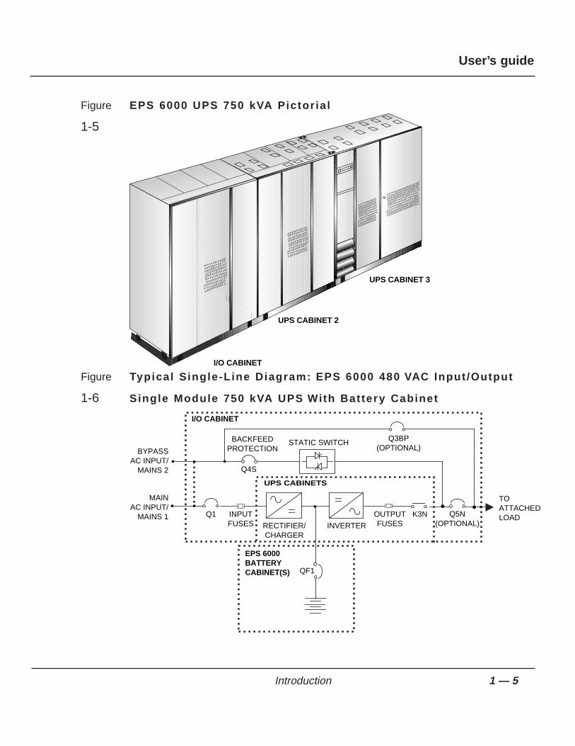
Figure EPS 6000 UPS 750 kVA Pictor ia l
1-5
Figure Typical Single-Line Diagram: EPS 6000 480 VAC Input /Output
1-6 Single Module 750 kVA UPS With Battery Cabinet
Q1
RECTIFIER/CHARGER
INVERTER
BACKFEEDPROTECTION
STATIC SWITCH Q3BP(OPTIONAL)
Q5N(OPTIONAL)
TOATTACHEDLOAD
QF1
BYPASSAC INPUT/
MAINS 2
MAIN AC INPUT/
MAINS 1 INPUTFUSES
OUTPUTFUSES
I/O CABINET
EPS 6000BATTERYCABINET(S)
K3N
Q4S
UPS CABINETS
UPS CABINET 3
I/O CABINET
UPS CABINET 2
1 — 5Introduction
User’s guide
Following is a description of the EPS 6000 UPS majorinternal components. Refer to the single-line diagramprovided in Figures 1-2, 1-4 and 1-6, and the componentlocators provided in Figure 1-7 through Figure 1-13.
The rectifier/battery charger converts the AC input voltagefrom the utility source into a DC voltage, supplying theinverter and regulating the charge of the battery system. Acapacitor bank filters the DC voltage.
The inverter chops the DC voltage supplied from either therectifier/battery charger or the battery system into a three-
phase AC voltage. An AC output filter is used to achieve a computer-grade sinewave outputvoltage waveform, with a total harmonic distortion of less than 2% under linear-load conditions.
During normal operation, the inverter transformer providescomplete electrical isolation between the UPS output to theattached load and the utility power source input as well asthe UPS battery source.
The static switch transfers the load between the inverteroutput and the bypass AC source without interrupting the
supply of power to the load, allowing the load to continue operation while the UPS is beingmaintained, or in the event of a UPS fault. The static switch circuit assures that voltage fromthe UPS output cannot feed back to the utility input lines.
The battery system stores energy for use by the inverter.The stored energy is utilized in the event that the AC input
power from the utility source fails, or falls outside of acceptable tolerance.
The battery system may be an MGE battery cabinet designed for operation with the EPS 6000UPS, or a customer-supplied battery installation. MGE-supplied EPS 6000 battery cabinetsmay be a provided as stand-alone enclosures, or as enclosures designed to be mountedadjacent to the EPS 6000 UPS module.
The EPS 6000 comes with a special battery ambient temperature sensor which allows theoptimization of the DC voltage level as a function of the temperature, ensuring that the batteryis properly charged and preserving its longevity.
1.2.5 Battery System
1.2.4 Static Switch
1.2.3 Inverter
Transformer
1.2.2 Inverter
1.2.1 Rectifier/Battery
Charger
1.2 Description of UPS
Module Major
Internal
Components
1 — 6 Introduction
EPS 6000 150 to 750 kVA Uninterruptible Power System

Figure EPS 6000 Major Internal Components,
1-7 Single-Module UPS 150 - 225 kVA
FRONT VIEW, DOORS AND COVERS REMOVED
TOP VIEW, COVER REMOVED
INVERTERS
ARUZ PCA (BEHIND MTG. PLATE)
MAINTENANCE BYPASSCIRCUIT BREAKERS(OPTIONAL)
NEUTRAL CONNECTION(BEHIND BYPASS & OUTPUT)
OUTPUT XFMR(BEHIND BREAKERS)
ACOZ PCA K3NZ PCA
ACUZ PCA
RAUZ PCA DC CAPACITORS
OUTPUT FUSES F7, F8, F9
120V AC OUTLET(FOR MGE USE ONLY)
(BEHIND EACH INVERTER)OBEZ PCA
IBEZ PCA
FANTRANSFORMER
FB9
1- GTCZ PCA2- SRIZ PCA3- CRIZ PCA4- CROZ / DO6Z PCA5- AROZ PCA6- ALEZ PCA
CARD CAGE:
ALBZ
CHARGER, STATIC SW,
INPUTCONNECTIONS
GROUNDCONNECTIONS
BYPASSCONNECTIONS
BATTERYCONNECTIONS
OUTPUTCONNECTIONS
Q4S
K4S
K3N
1
C3B3A3
BAIZ & TREZ(BEHIND PLATE)
EPOZ
INPUT FUSES F1, F2, F3
FUSES F16, F17F18, F19
FUSES F4, F5, F6FUSES F20, F21, F22
FB1 TO FB8
F10,F11 RATED 2A,500VDC
AC CAPACITORASSEMBLY
FANS(x 6)
6543
1 2
FB4FB3FB2FB1
FB8FB7FB6FB5
C4B4A4C5B5A5+
2 3 4 5 6
INVERTER FUSES (BEHIND)
Q1 Q3BP Q5N
1 — 7Introduction
User’s guide

Figure EPS 6000 Major Internal Components,
1-8 Single-Module UPS 300/375 kVA
FRONT VIEW, DOORS AND COVERS REMOVED
TOP VIEW, COVER REMOVED
INVERTERS (x6)
ARUZ PCA (BEHIND MTG. PLATE)
MAINTENANCE BYPASSCIRCUIT BREAKERS(OPTIONAL)
NEUTRAL CONNECTION(BEHIND BYPASS & OUTPUT)
OUTPUT XFMR(BEHIND BREAKERS)
ACOZ PCA K3NZ PCA
ACUZ PCA
RAUZ PCA DC CAPACITORS
OUTPUT FUSES F7, F8, F9
120V AC OUTLET(FOR MGE USE ONLY)
(BEHIND EACH INVERTER)OBEZ PCA
IBEZ PCA
FANTRANSFORMER
FB9
1- GTCZ PCA2- SRIZ PCA3- CRIZ PCA4- CROZ / DO6Z PCA5- AROZ PCA6- ALEZ PCA
CARD CAGE:
ALBZ
CHARGER, STATIC SW,
INPUTCONNECTIONS
GROUNDCONNECTIONS
BYPASSCONNECTIONS
BATTERYCONNECTIONS
OUTPUTCONNECTIONS
Q4S
K4S
K3N
1
C3B3A3
BAIZ & TREZ(BEHIND PLATE)
EPOZ
INPUT FUSES F1, F2, F3
FUSES F16, F17F18, F19
FUSES F4, F5, F6FUSES F20, F21, F22
FB1 TO FB8
F10,F11 RATED 2A,500VDC
AC CAPACITORASSEMBLY
FANS(x 6)
6
6
54321
543
1 2
FB4FB3FB2FB1
FB8FB7FB6FB5
C4B4A4C5B5A5+
2 3 4 5 6
INVERTER FUSES (BEHIND)F24,F26,F28,F30,F32,F34
Q1 Q3BP Q5N
1 — 8 Introduction
EPS 6000 150 to 750 kVA Uninterruptible Power System

F igure EPS 6000 Major Internal Components
1-9 500kVA UPS Cabinet
FRONT VIEW, DOORS AND COVERS REMOVED
TOP VIEW, COVER REMOVED
AC CAP ASSY.
K1
BATTERYCONNECTION(OPTIONAL)
F10,F11,F18,F19
F12,F13
ALBZ
ACPZ
INVERTERS (x6)
DC CAPACITERS(BEHIND EACH INVERTER)
RAUZ
OBEZ
IBEZ
FANTRANSFORMER
OUTPUT FUSESF7, F8, F9
K3N
STATIC SWITCH
K3NZ
1- GTCZ PCA2- SRIZ PCA3- CRIZ PCA4- CROZ / DO6Z PCA5- AROZ PCA6- ALEZ PCA
CARD CAGE:
AC OUTPUTCAPACITORS
CHARGER & TREZ(BEHIND PLATE)
EPOZ
FB1 TO FB8
AC CAPACITORASSEMBLY
FANS(x 8)
6
6
5
NEUTRAL
4321
1 2 3 4 5 6
543
7 81 2
1 — 9Introduction
User’s guide

Figure EPS 6000 Major Internal Components
1-10 500 kVA Input /Output Cabinet
Q1
A3 B3 C3
INPUTCONNECTIONS
Q4S
A5 B5 C5
BYPASSCONNECTIONS
Q3BP
A4 B4 C4
OUTPUTCONNECTIONS
BATTERYCONNECTIONS
Q5N(OPTIONAL) (OPTIONAL)
FRONT VIEW, DOORS AND COVERS REMOVED
TOP VIEW, COVERS REMOVED
A12 B12 C12
A2
C1B1A1
N12
C2
B2
GROUND CONNECTION
BONDINGJUMPER
SHUNT
L2
CURRENT XFMRS
BAIZ
ACUZARUZ
SSSZ
STATIC SWITH
L4
AC CAPACITORS
NEUTRAL CONNECTION
GROUNDCONNECTION
INPUT FUSESF1,F2,F3
FUSES F14,F15
FUSES F16,F17
L3
F20,F21,F22
1 — 10 Introduction
EPS 6000 150 to 750 kVA Uninterruptible Power System

Figure EPS 6000 Major Internal Components
1-11 750 kVA UPS Cabinet 1
DIYFConnection
Ground
Capacitors
Connection
PowerInterconnect CT (6ea)
SSSZ
ARUZ
ACUZ
Fuses
Relay
BatteryConnections
OutputConnections
BypassInput
Connections
Q4S Q3BP(optional)
Q5N(optional)
InputConnections
Bondingjumper
Shunt
CT (4ea)
Induction Filter(2 ea) one on
other side
AC capacitors(2ea) one on
other side
Induction filter(2ea) one on
other side
Cooling fans(2ea)
BAIZ
XFMER
Fuses
Input fusesF1, F2, F3
Resistors
NeutralConnection Choke
GroundConnection
( - )
( + )
Front view, doors, cover and some components removed for clarity.
Static Switch
Q1
A3 B3 C3 A5 B5 C5 A4 B4 C4 (+) (-)
Side View
Top view
1 — 11Introduction
User’s guide

Figure EPS 6000 Major Internal Components
1-12 750 kVA UPS Cabinet 2
FRONT VIEW, DOORS AND COVERS REMOVED
TOP VIEW, COVER REMOVED
INVERTERS (x6)
AC OUTPUTCAPACITOR ASSY
ALBZ
K3N
K3NZ
DC CAPACITORS(BEHIND EACH INVERTER)
FANTRANSFORMERFB9
OUTPUT FUSES
FB1 TO FB8
AC CAPACITORASSEMBLY
FANS(x 8)
6
6
54321
543
7 8
1 2
FB4FB3FB2FB1
FB8FB7FB6FB5
INVERTER FUSES (BEHIND)F24,F26,F28,F30,F32,F34
F10,F11
NEUTRAL
1 — 12 Introduction
EPS 6000 150 to 750 kVA Uninterruptible Power System

Figure EPS 6000 Major Internal Components
1-13 750 kVA UPS Cabinet 3
FRONT VIEW, DOORS AND COVERS REMOVED
TOP VIEW, COVER REMOVED
INVERTERS (x6)
AC OUTPUTCAPACITOR ASSY
ALBZ
DOUZ
RAUZ PCA DC CAPACITORS(BEHIND EACH INVERTER)
OBEZ PCA
IBEZ PCA
FANTRANSFORMER
FB9
1- GTCZ PCA2- SRIZ PCA3- CRIZ PCA4- CROZ / DO6Z PCA5- AROZ PCA6- ALEZ PCA
CARD CAGE:
OUTPUT FUSES
POWERINTERCONNECT
1
EPOZ
FB1 TO FB8
AC CAPACITORASSEMBLY
FANS(x 8)
6
6
54321
543
1 2
FB4FB3FB2FB1
FB8FB7FB6FB5
2 3 4 5 6
INVERTER FUSES (BEHIND)F24,F26,F28,F30,F32,F34
F10,F11
ACOZ
1 — 13Introduction
User’s guide

This section describes options available for the EPS 6000UPS. Some configurations do not support some options.
Most options must be specified at the time of equipment order; some options can be installedin the field. Contact your MGE dealer for complete information.
Electrical room package The electrical room package option allows configuration of all input and output cables, orselected cables, through the top of the enclosures. It features separate main AC input(mains 1) and bypass AC input (mains 2) feeder support. The electrical room package isstandard on all EPS 6000 modules configured for shared systems.
Computer room package The computer room package option allows configuration of the EPS 6000 UPS using asingle utility AC source for both main AC input (mains 1) and bypass AC input voltage(mains 2). The computer room option includes additional filtering, making the EPS 6000UPS fully compliant with the requirements of FCC part 15, subpart J, class A, and theNational Electrical Code (NEC) article 645, Electronic Computer/Data ProcessingEquipment
Additional battery cabinetsUp to a maximum of four battery cabinets can be supplied for a single EPS 6000 UPSmodule, making additional back-up time available during power outages.
Input filter An input harmonic current filter is available for the EPS 6000 UPS. For some power levels,the input filter is installed within the UPS enclosure. For others, the input filter is installedin an auxiliary cabinet.
Input or output transformersThe single-module EPS 6000 UPS can be equipped with an isolation or autotransformeron both the input and output. The transformer provides battery isolation or voltage step-upor step-down as required for the particular installation.
High interrupting capacity circuit breakersThe EPS 6000 UPS module is normally equipped with circuit breakers rated at 30 kAIC.As an option, these breakers can be provided with a rating of 65 kAIC.
Maintenance bypass The maintenance bypass option provides a direct bypass AC input source (mains 2) thatcan be used to supply the load while the UPS module is being serviced.
Output distribution cabinetSome single-module EPS 6000 systems can be provided with a output distribution cabinet,with up to four output circuit breakers.
Remote alarm status panel (RASP)A remote alarm status panel (RASP) is available. The RASP allows the following statusindications to be viewed from a remote location:• UPS on line
1.3 Options
1 — 14 Introduction
EPS 6000 150 to 750 kVA Uninterruptible Power System

• UPS on battery
• UPS on bypass
• UPS on maintenance bypass
• Low battery shutdown
• Charger on
• Overload
• Charger fault
• Inverter fault
• Transfer lockout
• Summary alarm
Additionally, the RASP contains an audible alarm and two pushbuttons:• UPS test/reset pushbutton
• Audio reset pushbutton
Remote summary alarm panel (RSAP)A remote summary alarm panel (RSAP) is available. The RSAP allows the following statusindications to be viewed from a remote location:• UPS summary alarm
• UPS on battery
Additionally, the RSAP contains an audible alarm and two pushbuttons:• Alarm test/reset pushbutton
• Audio reset pushbutton
ES/9000 interfaceAn interface to an IBM ES/9000 mainframe computer is available. This option providesfour (4) sets of normally-open, isolated dry contacts, connected to a 9-pin DB-9 femaleconnector, located on the inside cable entry point of the EPS 6000 UPS enclosure. Thefour sets of contacts indicate:• UPS on line
• UPS on bypass
• UPS on battery
• Low battery, shutdown imminent
The interface is provided with a 15-foot long 9-pin cable that connects the EPS 6000 to theIBM ES/9000 computer.
Active RS-232/RS-485A communications port is available that allows the UPS to be monitored from a remoteterminal or computer. For detailed information on the communication features, contactyour MGE dealer.
1 — 15Introduction
User’s guide

Specifications provided refer to an EPS 6000 UPS moduleand any required auxiliary cabinets.
AC input ratingsVoltage: 208 or 480 VAC, +10%, -15%Frequency: 60 Hz, ± 10%Phases: 3 Ø (phase sequence must be A, B, C)Wires: 3 or 4 wires plus groundCurrent:
Power factor: Up to 0.9 lagging; 0.95 with optional input harmonic filter
AC output ratingsVoltage: 480 VAC ± 0.5% (steady-state conditions)
480 VAC ± 5% (transient conditions from 0% to 100% or 100% to 0%)
Frequency: 60 Hz ± 0.1% (free-running)Phases: 3 Ø (phase sequence must be A, B, C)Wires: 4 wires plus groundCurrent:
Power factor: 0.8 laggingTotal harmonic distortion (THD): < 2% (linear load)
< 4% (for 100% non-linear load with a crest factor of up to 3.5)
Dynamic regulation: ± 0.5% for balanced load± 2.5% for 100% unbalanced load
Dynamic response: ± 5% for 100% step load changeOverload: 125% of rated load for 10 minutes
150% of rated load for 1 minute
AVknignitar 051 522 003 573 005 057
CAV802@serepmA 614 526 338 140,1 A/N A/N
CAV084@serepmA 081 172 163 154 106 209
AVknignitar 051 522 003 573 005 057
CAV802@serepmA 064 086 009 001,1 A/N A/N
CAV084@serepmA 002 003 004 094 207 089
1.4.1 Electrical
1.4 Specifications, UPS
Modules
1 — 16 Introduction
EPS 6000 150 to 750 kVA Uninterruptible Power System

DC ratingsBattery voltage: 545 VDC float
480 VDC nominal390 VDC minimum
Height: 1,905 mm (75”)Depth: 815 mm (32”)Width: See Table 1-1Weight: See Table 1-1Finish: MGE light gray
Recommended environment: 20° to 25° C (68° to 77° F.); 50% relative humidity;
computer room or other temperature- and humidity-controlled environment
Operating temperature: 0° to 40° C (32° to 104° F.) except batteryStorage: -20° to 50° C (-4° to 122° F.)Humidity: up to 90% non-condensing (operating)Altitude: sea level to 1,000 meters (sea level to 3,280 feet)
without derating; 1,000 to 2,000 meters (3,280 to 6,560feet): derate operating temperature to a maximum of 28°C (82° F)
Acoustic noise:
AVknignitar 051 522 003 573 005 057
detartaesioncitsuoccAteef5taABdnidaol
fotnorfehtmorfeludomSPUeht 27 27 27 27 57 87
1.4.3 Environmental
1.4.2 Mechanical
AVknignitar 051 522 003 573 005 057
tnerrucyrettabmumixaM)CDA(egatlovffo-tucta
323 584 746 908 470,1 026,1
1 — 17Introduction
User’s guide

(this page left blank intentionally)
EPS 6000 150 to 750 kVA Uninterruptible Power System
This section presents operating information for the singleEPS 6000 UPS module, including an overview of the
system, its components, and their function; a description of the indicators and controls andtheir function; and operational sequences to be followed for all conditions of normal,emergency, and maintenance operation.
This section presents an overview of the system operation.
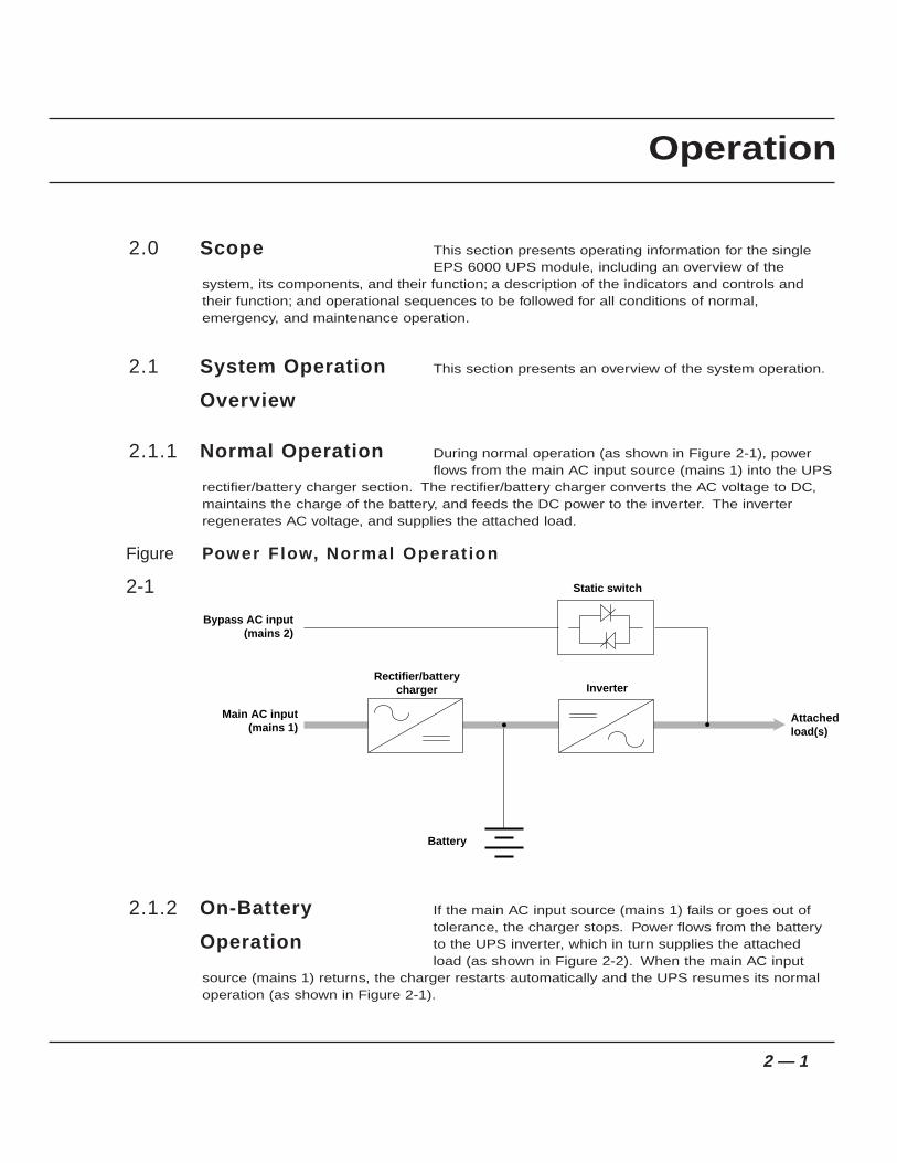
During normal operation (as shown in Figure 2-1), powerflows from the main AC input source (mains 1) into the UPS
rectifier/battery charger section. The rectifier/battery charger converts the AC voltage to DC,maintains the charge of the battery, and feeds the DC power to the inverter. The inverterregenerates AC voltage, and supplies the attached load.
Figure Power Flow, Normal Operat ion
2-1
If the main AC input source (mains 1) fails or goes out oftolerance, the charger stops. Power flows from the batteryto the UPS inverter, which in turn supplies the attachedload (as shown in Figure 2-2). When the main AC input
source (mains 1) returns, the charger restarts automatically and the UPS resumes its normaloperation (as shown in Figure 2-1).
2.1.2 On-Battery
Operation
Bypass AC input(mains 2)
Main AC input(mains 1)
Rectifier/batterycharger Inverter
Battery
Static switch
Attachedload(s)
2.1.1 Normal Operation
2.1 System Operation
Overview
2.0 Scope
2 — 1
Operation

If the battery becomes depleted before the main AC input source (mains 1) returns, theinverter stops and the attached load is transferred to the bypass AC input source (mains 2) if itis available (as shown in Figure 2-3).
Figure Power Flow, On-battery Operat ion
2-2
Figure Power Flow, Bypass Operat ion
2-3
Indicators and controls are located in three places on theUPS cabinet: on the front panel, behind a drop-down coverjust below the front panel, and inside the cabinet doors, asshown in Figure 2-4. In battery cabinets and auxiliarycabinets, the controls are located behind the cabinet doors.
2.2 Indicators and
Controls
Bypass AC input(mains 2)
Main AC input(mains 1)
Rectifier/batterycharger Inverter
Battery
Static switch
Attachedload(s)
Bypass AC input(mains 2)
Main AC input(mains 1)
Rectifier/batterycharger Inverter
Battery
Static switch
Attachedload(s)
2 — 2 Operation
EPS 6000 150 to 750 kVA Uninterruptible Power System
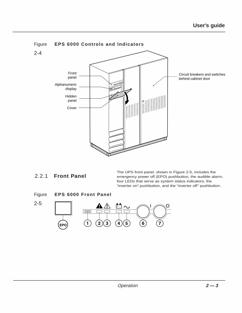
Figure EPS 6000 Controls and Indicators
2-4
The UPS front panel, shown in Figure 2-5, includes theemergency power off (EPO) pushbutton, the audible alarm,four LEDs that serve as system status indicators, the“inverter on” pushbutton, and the “inverter off” pushbutton.
Figure EPS 6000 Front Panel
2-5
2.2.1 Front Panel
Circuit breakers and switchesbehind cabinet door
Frontpanel
Hiddenpanel
Cover
Alphanumericdisplay
2 — 3Operation
User’s guide

Emergency power off (EPO)
On the left side of the front panel, an emergency power off (EPO) pushbutton isprovided, with a protective cover to guard against inadvertent operation. Thispushbutton, when activated, disconnects the main AC input (mains 1), bypass ACinput (mains 2), and battery power to the UPS, and disconnects output power tothe attached load.
Audible alarm (Figure 2-5, item 1)The audible alarm provides an audible warning to the operator by sounding apulsed “beep” when any of the following conditions occur:
• Load transferred to bypass (mains 2)
• Load supplied via battery
• Operating problem
During minor alarm conditions, the alarm sounds at a slow rate and a low soundlevel. When the battery approaches the low-voltage shutdown level, the alarmsounds louder and at an increased rate. If the inverter shuts down, the alarmsounds loudly and continuously.
An audible alarm reset is located on the hidden panel (see Figure 2-7). Pressing itwill silence the alarm. Should a higher-level alarm condition occur after the resethas been activated, the audible alarm will sound the new alarm condition.
¡ Load not protected LED (2)This red LED turns on when any of these conditions occur:
• The load is no longer protected following an inverter shutdown, or theopening of the isolation circuit breaker (Q5N)
• The battery circuit breaker QF1 is open, making battery power unavailable
Pressing the EPO disconnects the attached load. The emergency power of f (EPO) is to be used during emergency situations only, where a hazard to personnel or equipment exists, such as during a f ire . DO NOT USE THE EPO TO TURN THE UPS ON OR OFF; fo l low the procedures l is ted in th is section for turning on and off the inver ter.
CAUTION
2 — 4 Operation
EPS 6000 150 to 750 kVA Uninterruptible Power System

⁄ Operating problem LED (3)This orange LED turns on when an operating problem exists, such as fan failure;static switch power supply fault; battery temperature fault; overload fault; or bypassAC input (mains 2) out of tolerance. The UPS continues to protect the attachedload.
ı Battery operation LED (4)This orange LED turns on to indicate that the attached load is being partially orcompletely supplied by the battery. When the main AC input (mains 1) fails or isoutside tolerance, stored battery energy is supplied to the inverter, which in turnsupplies the load.
Í Load protected LED (5)This green LED indicates that the attached load is supplied by the inverter andprotected by the battery. During normal operation, this LED is the only one that ison.
Inverter on (6)This green pushbutton is used to start the inverter. When it is pushed, the green “loadprotected” LED flashes for three seconds, indicating that the start command has beenreceived. When the inverter has synchronized with the bypass AC input (mains 2) source,the static switch transfers the load to the inverter output.If the inverter cannot synchronize to the bypass AC input (mains 2) source, the load mustbe forced to transfer using the hidden panel (see Section 2.4.6, Forced Transfers).
Inverter off (7)This gray pushbutton is used to stop the inverter. When it is pressed for 3 seconds, theinverter stops and the load is transferred to the bypass AC input (mains 2) source. If theuninterrupted transfer conditions are not met, this pushbutton has no effect and theinverter can be stopped only from the hidden panel (see Section 2.4.6, Forced Transfers).
The alphanumeric display is located on the hidden panel,directly below the front panel, behind the hinged cover, asshown in Figure 2-4. For complete instructions, refer toSection 2.3, Using the Alphanumeric Display. A briefdescription of the display and controls follows:
Two-line alphanumeric display (Figure 2-6)This 40-character, two line LCD displays general status of the UPS continuously,and displays measurements of UPS operating parameters as selected with thecontrol pushbuttons.
2.2.2 Alphanumeric
Display and
Controls
2 — 5Operation
User’s guide
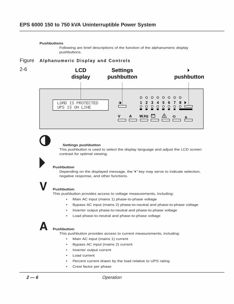
PushbuttonsFollowing are brief descriptions of the function of the alphanumeric displaypushbuttons.
Figure Alphanumeric Display and Controls
2-6
ø Settings pushbuttonThis pushbutton is used to select the display language and adjust the LCD screencontrast for optimal viewing.
˘ PushbuttonDepending on the displayed message, the “˘” key may serve to indicate selection,negative response, and other functions.
◊ PushbuttonThis pushbutton provides access to voltage measurements, including:
• Main AC input (mains 1) phase-to-phase voltage
• Bypass AC input (mains 2) phase-to-neutral and phase-to-phase voltage
• Inverter output phase-to-neutral and phase-to-phase voltage
• Load phase-to-neutral and phase-to-phase voltage
Å PushbuttonThis pushbutton provides access to current measurements, including:
• Main AC input (mains 1) current
• Bypass AC input (mains 2) current
• Inverter output current
• Load current
• Percent current drawn by the load relative to UPS rating
• Crest factor per phase
LCDdisplay
Settingspushbutton
˘pushbutton
87654321
+ – !W.HzAV *
LOAD IS PROTECTEDUPS IS ON LINE
2 — 6 Operation
EPS 6000 150 to 750 kVA Uninterruptible Power System

„ PushbuttonThis pushbutton provides access to power and frequency measurements, including:
• Main AC input (mains 1) frequency
• Bypass AC input (mains 2) frequency
• Inverter frequency
• Power drawn by the load (in kW and kVA)
• Load power factor
ı Battery pushbuttonThis pushbutton provides access to battery measurements, including:
• Battery voltage
• Battery current
• Battery ambient temperature
• Battery time available
• Battery time remaining
⁄ Alarms pushbutton
This pushbutton is used to display current alarms, or to display stored alarms.
If the alarm key is pressed repeatedly, the display will scroll through the storedalarm record, returning to the latest after the oldest is shown.
If a blinking character (!) appears in the display, the user may press the Alarmpushbutton again to scroll through additional useful information.
ØOn/off pushbuttonThis pushbutton is reserved for future use.
° PushbuttonDepending on the displayed message, this pushbutton may serve to indicate confir-mation, positive response, and other functions.
Numbered lightsDuring normal operation, the green LED #1 will be on, indicating that the UPS corecontroller communicates with the display. If there is an alarm condition, the red LED #1will turn on.
2 — 7Operation
User’s guide

The hidden panel is located directly below the front panel,behind the hinged cover, as shown in Figure 2-4. The
hidden panel includes the following controls and indicators as shown in figure 2-7:
Figure Hidden Panel
2-7
Alphabetical lightsFourteen alphabetically labeled LEDs provide detailed information on UPS statusas follows:
A: Emergency shutdown
This red LED indicates that the emergency power off (EPO) or remote emergencypower off (REPO) has been activated (see Section 2.4.4.1, Emergency power off).
B: Rectifier/charger on
This green LED indicates that the rectifier/battery charger is on.
C: Rectifier/charger fault
This red LED indicates an alarm condition within the rectifier/battery charger. itindicates the presence of one of the following fault conditions:
• Input circuit breaker Q1 open
• Input power protection fuse blown
• Rectifier/battery charger over-temperature
• Battery charge overcurrent
• Battery overvoltage
Test connector
Clear faults
Alarm reset
Battery charge cycle
Return to float voltage
Security
Inverter sync/desync
Forced transfer
Forced shutdown
Emergency shutdown
Rectifier/charger on
Rectifier/charger fault
Input outside tolerance
Battery temp. outside tolerance
Battery charging
Inverter fault
Low batt. shutdown imminent
Inverter desynchronized
Transfer fault
Overload
Bypass outside tolerance
Maintenance position
NMLKJIHGFEDCBA
1 2 3 4 5fault
2.2.3 Hidden Panel
2 — 8 Operation
EPS 6000 150 to 750 kVA Uninterruptible Power System
• Rectifier/battery charger control board fault
• Power supply board fault
D: Main AC input (mains 1) outside tolerance
This orange LED indicates that the main AC input (mains 1) source is outsidetolerance (voltage and/or frequency too high or too low).
E: Reserved for future use.
F: Battery temperature outside tolerance
This orange LED indicates that the ambient temperature of the battery is too highor too low.
G: Battery charging
This orange LED indicates that the battery is being recharged. This LED functionsonly when the connected battery is of the vented lead-acid type (sealed lead-acidbatteries will not activate this signal).
H: Inverter fault
This red LED indicates an alarm condition in the inverter, which may be one ormore of the following conditions:
• Inverter shutdown due to output voltage out of tolerance
• Inverter output protection fuse blown
• Inverter leg fault
• Inverter output transformer over-temperature
• Inverter leg over-temperature
• Internal clock fault
• Inverter control board fault
• Power supply board fault
I: Battery discharged
This orange LED indicates that the battery has reached the end of its autonomy,shutting down the inverter.
J: Inverter desynchronized
This orange LED indicates that the inverter is not synchronized with the bypass ACinput (mains 2).
K: Transfer fault
This red LED indicates a transfer fault, which may be one or more of the followingconditions:
• Inverter output contactor K3N fault
• Static switch over-temperature
• Static switch power supply fault
• Transfer control board fault
• Power supply board fault
2 — 9Operation
User’s guide

L: Overload
This orange LED indicates an alarm condition resulting from one or more of thefollowing conditions:
• Inverter current above rating
• Output current above rating
• Inverter and/or static switch shutdown due to excessive load current
M: Bypass AC input (mains 2) outside tolerance
This orange LED indicates that the bypass AC input (mains 2) voltage and/orfrequency are too high or too low.
N: Maintenance position
This orange LED indicates that circuit breakers QF1, Q4S, Q5N, or Q3BP are setto the maintenance position. The UPS is not available for load protection.
Test connector (Figure 2-8)This 9-pin connector is reserved for service. It is used to connect the cabinet to acomputer, allowing system calibration, personalization, and computer-aideddiagnostics.
PushbuttonsFollowing are brief descriptions of the function of the hidden panel pushbuttons,shown in Figure 2-8.
Clear fault log Pressing this pushbutton clears the alarms stored in memory, allowing the unit torestart. Memorized alarms cannot be cleared until the condition causing the alarmhas been corrected.
Audible alarm resetPressing this pushbutton stops the audible alarm. Should a new fault condition ata higher alarm level occur, the alarm will sound again.
Battery charge cycle (pushbutton #1)Pressing this pushbutton begins a battery charging cycle. After the cycle iscomplete, the rectifier/battery charger returns to float charge levels on the battery.The battery charge cycle is not applicable to sealed lead-acid battery installations.
Return to float voltage (pushbutton #2)This pushbutton can be used during a battery charge cycle to force therectifier/battery charger back to the float voltage level.
Security pushbutton (key)This pushbutton must be pressed simultaneously with any of the following threepushbuttons. This helps guard against inadvertent transfer of the load with inter-ruption.
2 — 10 Operation
EPS 6000 150 to 750 kVA Uninterruptible Power System
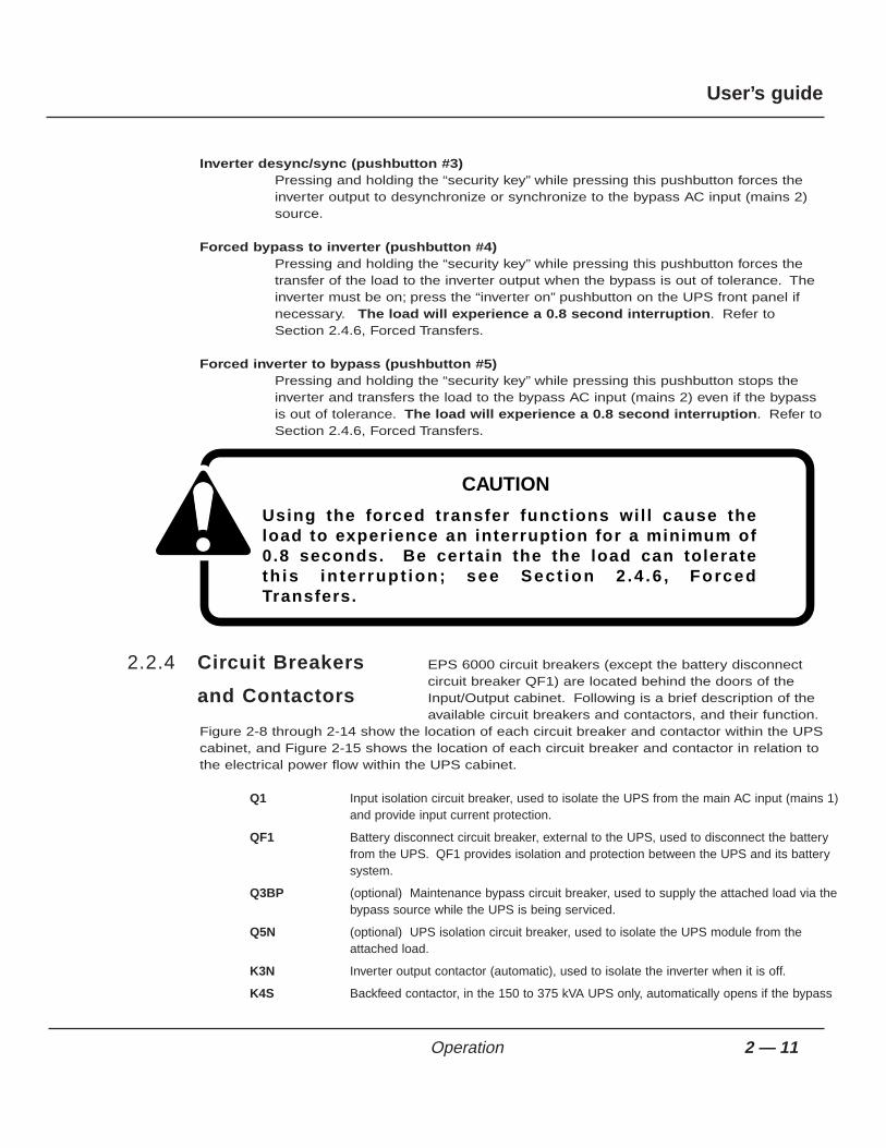
Inverter desync/sync (pushbutton #3)Pressing and holding the “security key” while pressing this pushbutton forces theinverter output to desynchronize or synchronize to the bypass AC input (mains 2)source.
Forced bypass to inverter (pushbutton #4)Pressing and holding the “security key” while pressing this pushbutton forces thetransfer of the load to the inverter output when the bypass is out of tolerance. Theinverter must be on; press the “inverter on” pushbutton on the UPS front panel ifnecessary. The load will experience a 0.8 second interruption. Refer toSection 2.4.6, Forced Transfers.
Forced inverter to bypass (pushbutton #5)Pressing and holding the “security key” while pressing this pushbutton stops theinverter and transfers the load to the bypass AC input (mains 2) even if the bypassis out of tolerance. The load will experience a 0.8 second interruption. Refer toSection 2.4.6, Forced Transfers.
EPS 6000 circuit breakers (except the battery disconnectcircuit breaker QF1) are located behind the doors of theInput/Output cabinet. Following is a brief description of theavailable circuit breakers and contactors, and their function.
Figure 2-8 through 2-14 show the location of each circuit breaker and contactor within the UPScabinet, and Figure 2-15 shows the location of each circuit breaker and contactor in relation tothe electrical power flow within the UPS cabinet.
Q1 Input isolation circuit breaker, used to isolate the UPS from the main AC input (mains 1)and provide input current protection.
QF1 Battery disconnect circuit breaker, external to the UPS, used to disconnect the batteryfrom the UPS. QF1 provides isolation and protection between the UPS and its batterysystem.
Q3BP (optional) Maintenance bypass circuit breaker, used to supply the attached load via thebypass source while the UPS is being serviced.
Q5N (optional) UPS isolation circuit breaker, used to isolate the UPS module from theattached load.
K3N Inverter output contactor (automatic), used to isolate the inverter when it is off.
K4S Backfeed contactor, in the 150 to 375 kVA UPS only, automatically opens if the bypass
2.2.4 Circuit Breakers
and Contactors
Using the forced transfer functions wil l cause the load to experience an interruption for a minimum of 0.8 seconds. Be cer tain the the load can tolerate th is in ter rupt ion; see Sect ion 2 .4 .6 , Forced Transfers.
CAUTION
2 — 11Operation
User’s guide

upstream power is removed.
Q4S In the 150 to 375 kVA UPS, it is a control circuit breaker; it controls the function of thebackfeed contactor K4S. When Q4S is open, K4S is always open. When Q4S is closed,K4S functions automatically to provide backfeed protection.
Q4S In the 500 and 750 kVA UPSs, it is a power circuit breaker; it is used to isolate the UPSfrom the bypass input (mains 2) source and provide backfeed protection.
Figure EPS 6000 Major Internal Components,
2-8 Single-Module UPS 150 - 225 kVA
FRONT VIEW, DOORS AND COVERS REMOVED
TOP VIEW, COVER REMOVED
INVERTERS
ARUZ PCA (BEHIND MTG. PLATE)
MAINTENANCE BYPASSCIRCUIT BREAKERS(OPTIONAL)
NEUTRAL CONNECTION(BEHIND BYPASS & OUTPUT)
OUTPUT XFMR(BEHIND BREAKERS)
ACOZ PCA K3NZ PCA
ACUZ PCA
RAUZ PCA DC CAPACITORS
OUTPUT FUSES F7, F8, F9
120V AC OUTLET(FOR MGE USE ONLY)
(BEHIND EACH INVERTER)OBEZ PCA
IBEZ PCA
FANTRANSFORMER
FB9
1- GTCZ PCA2- SRIZ PCA3- CRIZ PCA4- CROZ / DO6Z PCA5- AROZ PCA6- ALEZ PCA
CARD CAGE:
ALBZ
CHARGER, STATIC SW,
INPUTCONNECTIONS
GROUNDCONNECTIONS
BYPASSCONNECTIONS
BATTERYCONNECTIONS
OUTPUTCONNECTIONS
Q4S
K4S
K3N
1
C3B3A3
BAIZ & TREZ(BEHIND PLATE)
EPOZ
INPUT FUSES F1, F2, F3
FUSES F16, F17F18, F19
FUSES F4, F5, F6FUSES F20, F21, F22
FB1 TO FB8
F10,F11 RATED 2A,500VDC
AC CAPACITORASSEMBLY
FANS(x 6)
6543
1 2
FB4FB3FB2FB1
FB8FB7FB6FB5
C4B4A4C5B5A5+
2 3 4 5 6
INVERTER FUSES (BEHIND)
Q1 Q3BP Q5N
2 — 12 Operation
EPS 6000 150 to 750 kVA Uninterruptible Power System

Figure EPS 6000 Major Internal Components,
2-9 Single-Module UPS 300/375 kVA
FRONT VIEW, DOORS AND COVERS REMOVED
TOP VIEW, COVER REMOVED
INVERTERS (x6)
ARUZ PCA (BEHIND MTG. PLATE)
MAINTENANCE BYPASSCIRCUIT BREAKERS(OPTIONAL)
NEUTRAL CONNECTION(BEHIND BYPASS & OUTPUT)
OUTPUT XFMR(BEHIND BREAKERS)
ACOZ PCA K3NZ PCA
ACUZ PCA
RAUZ PCA DC CAPACITORS
OUTPUT FUSES F7, F8, F9
120V AC OUTLET(FOR MGE USE ONLY)
(BEHIND EACH INVERTER)OBEZ PCA
IBEZ PCA
FANTRANSFORMER
FB9
1- GTCZ PCA2- SRIZ PCA3- CRIZ PCA4- CROZ / DO6Z PCA5- AROZ PCA6- ALEZ PCA
CARD CAGE:
ALBZ
CHARGER, STATIC SW,
INPUTCONNECTIONS
GROUNDCONNECTIONS
BYPASSCONNECTIONS
BATTERYCONNECTIONS
OUTPUTCONNECTIONS
Q4S
K4S
K3N
1
C3B3A3
BAIZ & TREZ(BEHIND PLATE)
EPOZ
INPUT FUSES F1, F2, F3
FUSES F16, F17F18, F19
FUSES F4, F5, F6FUSES F20, F21, F22
FB1 TO FB8
F10,F11 RATED 2A,500VDC
AC CAPACITORASSEMBLY
FANS(x 6)
6
6
54321
543
1 2
FB4FB3FB2FB1
FB8FB7FB6FB5
C4B4A4C5B5A5+
2 3 4 5 6
INVERTER FUSES (BEHIND)F24,F26,F28,F30,F32,F34
Q1 Q3BP Q5N
2 — 13Operation
User’s guide

Figure Single EPS 6000 500 kVA Major Internal Components
2-10 UPS Cabinet
FRONT VIEW, DOORS AND COVERS REMOVED
TOP VIEW, COVER REMOVED
AC CAP ASSY.
K1
BATTERYCONNECTION(OPTIONAL)
F10,F11,F18,F19
F12,F13
ALBZ
ACPZ
INVERTERS (x6)
DC CAPACITERS(BEHIND EACH INVERTER)
RAUZ
OBEZ
IBEZ
FANTRANSFORMER
OUTPUT FUSESF7, F8, F9
K3N
STATIC SWITCH
K3NZ
1- GTCZ PCA2- SRIZ PCA3- CRIZ PCA4- CROZ / DO6Z PCA5- AROZ PCA6- ALEZ PCA
CARD CAGE:
AC OUTPUTCAPACITORS
CHARGER & TREZ(BEHIND PLATE)
EPOZ
FB1 TO FB8
AC CAPACITORASSEMBLY
FANS(x 8)
6
6
5
NEUTRAL
4321
1 2 3 4 5 6
543
7 81 2
2 — 14 Operation
EPS 6000 150 to 750 kVA Uninterruptible Power System
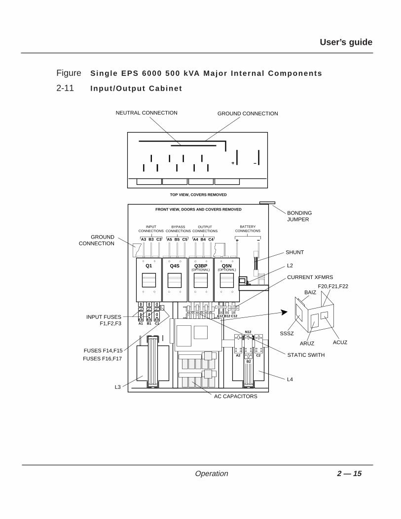
Figure Single EPS 6000 500 kVA Major Internal Components
2-11 Input /Output Cabinet
Q1
A3 B3 C3
INPUTCONNECTIONS
Q4S
A5 B5 C5
BYPASSCONNECTIONS
Q3BP
A4 B4 C4
OUTPUTCONNECTIONS
BATTERYCONNECTIONS
Q5N(OPTIONAL) (OPTIONAL)
FRONT VIEW, DOORS AND COVERS REMOVED
TOP VIEW, COVERS REMOVED
A12 B12 C12
A2
C1B1A1
N12
C2
B2
GROUND CONNECTION
BONDINGJUMPER
SHUNT
L2
CURRENT XFMRS
BAIZ
ACUZARUZ
SSSZ
STATIC SWITH
L4
AC CAPACITORS
NEUTRAL CONNECTION
GROUNDCONNECTION
INPUT FUSESF1,F2,F3
FUSES F14,F15
FUSES F16,F17
L3
F20,F21,F22
2 — 15Operation
User’s guide

Figure Single EPS 6000 500 kVA Major Internal Components
2-12 UPS Cabinet 1
DIYFConnection
Ground
Capacitors
Connection
PowerInterconnect CT (6ea)
SSSZ
ARUZ
ACUZ
Fuses
Relay
BatteryConnections
OutputConnections
BypassInput
Connections
Q4S Q3BP(optional)
Q5N(optional)
InputConnections
Bondingjumper
Shunt
CT (4ea)
Induction Filter(2 ea) one on
other side
AC capacitors(2ea) one on
other side
Induction filter(2ea) one on
other side
Cooling fans(2ea)
BAIZ
XFMER
Fuses
Input fusesF1, F2, F3
Resistors
NeutralConnection Choke
GroundConnection
( - )
( + )
Front view, doors, cover and some components removed for clarity.
Static Switch
Q1
A3 B3 C3 A5 B5 C5 A4 B4 C4 (+) (-)
Side View
Top view
2 — 16 Operation
EPS 6000 150 to 750 kVA Uninterruptible Power System

Figure Single EPS 6000 500 kVA Major Internal Components
2-13 UPS Cabinet 2
FRONT VIEW, DOORS AND COVERS REMOVED
TOP VIEW, COVER REMOVED
INVERTERS (x6)
AC OUTPUTCAPACITOR ASSY
ALBZ
K3N
K3NZ
DC CAPACITORS(BEHIND EACH INVERTER)
FANTRANSFORMERFB9
OUTPUT FUSES
FB1 TO FB8
AC CAPACITORASSEMBLY
FANS(x 8)
6
6
54321
543
7 8
1 2
FB4FB3FB2FB1
FB8FB7FB6FB5
INVERTER FUSES (BEHIND)F24,F26,F28,F30,F32,F34
F10,F11
NEUTRAL
2 — 17Operation
User’s guide

Figure Single EPS 6000 500 kVA Major Internal Components
2-14 UPS Cabinet 3
FRONT VIEW, DOORS AND COVERS REMOVED
TOP VIEW, COVER REMOVED
INVERTERS (x6)
AC OUTPUTCAPACITOR ASSY
ALBZ
DOUZ
RAUZ PCA DC CAPACITORS(BEHIND EACH INVERTER)
OBEZ PCA
IBEZ PCA
FANTRANSFORMER
FB9
1- GTCZ PCA2- SRIZ PCA3- CRIZ PCA4- CROZ / DO6Z PCA5- AROZ PCA6- ALEZ PCA
CARD CAGE:
OUTPUT FUSES
POWERINTERCONNECT
1
EPOZ
FB1 TO FB8
AC CAPACITORASSEMBLY
FANS(x 8)
6
6
54321
543
1 2
FB4FB3FB2FB1
FB8FB7FB6FB5
2 3 4 5 6
INVERTER FUSES (BEHIND)F24,F26,F28,F30,F32,F34
F10,F11
ACOZ
2 — 18 Operation
EPS 6000 150 to 750 kVA Uninterruptible Power System
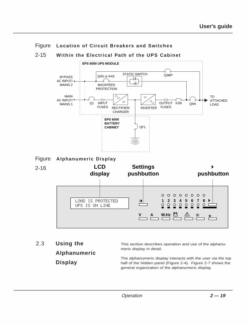
Figure Locat ion of Circuit Breakers and Switches
2-15 Within the Electr ical Path of the UPS Cabinet
Figure Alphanumeric Display
2-16
This section describes operation and use of the alphanu-meric display in detail.
The alphanumeric display interacts with the user via the tophalf of the hidden panel (Figure 2-4). Figure 2-7 shows thegeneral organization of the alphanumeric display.
2.3 Using the
Alphanumeric
Display
LCDdisplay
Settingspushbutton
˘pushbutton
87654321
+ – !W.HzAV *
LOAD IS PROTECTEDUPS IS ON LINE
Q1
RECTIFIER/CHARGER
INVERTER
BACKFEEDPROTECTION
STATIC SWITCH Q3BP
Q5N
TOATTACHEDLOAD
QF1
BYPASSAC INPUT/
MAINS 2
MAIN AC INPUT/
MAINS 1 INPUTFUSES
OUTPUTFUSES
EPS 6000 UPS MODULE
EPS 6000BATTERYCABINET
K3N
Q4S or K4S
2 — 19Operation
User’s guide

Figure General Display Configurat ion
2-17
During normal operation, when there are no alarm conditions present and the load is suppliedby the UPS inverter output, the display will present the general status message:
LOAD IS PROTECTEDUPS IS ON LINE
When there are alarm conditions, the display will present a general alarm message, and theuser can use the “alarm” pushbutton (!) to determine the exact cause of the alarm condition(see Section 2.3.2, Alarms).
The following sections present detailed operating instructions for the alphanumeric display.
The settings selection screens allow the user to configurethe display language and set the contrast of the LCDdisplay.
To access the settings selection screen, press the settings pushbutton, and follow the steps asindicated in Figure 2-18.
2.3.1 Settings
General status screen.This is the default display. It automatically reappearsif the control panel has not been used for ten minutes.
Alarm display
Voltage measurements
Current measurements
Frequency and power measurements
Battery measurements
Reserved for future use (on/off controls)
Language and screen contrast settings
V
+ –
!
A
W.Hz
°≥toset
toconfirm
toconfirm
*
2 — 20 Operation
EPS 6000 150 to 750 kVA Uninterruptible Power System

Figure Display Sett ings Display
2-18
In the event of an alarm condition, the general statusscreen shows an alarm message. To determine the specific
condition causing the alarm, press the alarm key on the front panel, as shown in Figure 2-7.
If there is a flashing exclamation mark (!) in the displayed message, there is additionalinformation to be viewed. Follow the steps as indicated in Figure 2-19.
Most alarm messages are self-explanatory; see Section 2.5 for a listing of the most commonalarm messages.
The most serious alarms are stored in the fault log, and may be viewed by following the stepsshown in Figure 2-19. To reset the alarms, press the “clear fault log” pushbutton (see Section2.2.3).
2.3.2 Alarms
Select ENGLISH U.S. as the display language to match the displays as presented in this manual.
IMPORTANT
LANGUAGE = ENGLISH U.S.≥=SELECT *=CONFIRM.
general status screen
DISPLAY CONTRAST≥=SELECT *=CONFIRM.
°
ø
°
Press the settings pushbutton to access the language selection menu.
Select the display language: French, English (U.K.), Spanish, Dutch, Italian, Swedish, Portugese, English (U.S.), German, or Finnish
Press the ° pushbutton to confirm the language selection and access the contrast selection menu.
Set the display contrast by pressing the ≥ pushbutton until the desired contrast is reached.
Press the ° pushbutton to confirm the contrast selection and return to the general status screen.
2 — 21Operation
User’s guide

Figure Displaying Alarm Messages
2-19
The LCD can display comprehensive information aboutUPS performance through its monitoring functions.
Figure 2-20 shows the location of measuring sensors within the UPS.
Figure Locat ion of Sensors Within the EPS 6000 UPS
2-20
Q1
RECTIFIER/CHARGER
INVERTER
STATIC SWITCH
Q5N TOATTACHEDLOAD
QF1
BYPASSAC INPUT/
MAINS 2
MAIN AC INPUT/
MAINS 1
EPS 6000 UPS MODULE
EPS 6000BATTERYCABINET
K3N
Q4S or K4S
CHARGERV, A, Hz
BATTERYV, A
INVERTERV, Hz, A, W LOAD
V, A, Hz, W
BYPASSV, Hz
Q3BP
2.3.3 Measurements
.
ALARM. . . !
⁄
⁄
⁄
(ALARM MESSAGE NUMBER 1)!
(LAST ALARM MESSAGE)
general status screen
This message on the general status screen indicates an alarm condition. The flashing exclamation mark ( ! ) indicates that there are alarm messages to view. To view them, press the "alarm" pushbutton.
The last alarm message is not followed by an exclamation mark ( ! ). When the "alarm" pushbutton is pressed again, the display will return to the general status screen.
2 — 22 Operation
EPS 6000 150 to 750 kVA Uninterruptible Power System

To display voltage measurements, press the “V” key on thekeyboard, as shown in Figure 2-21.
F igure Voltage Measurements
2-21 Select voltage measurements by
pressing the ◊ pushbutton
INPUT VAB VBC VCAV RMS
BYPASS VAN VBN VCNV RMS
BYPASS VAB VBC VCAV RMS
INV. VAN VBN VCNV RMS
INV. VAB VBC VCAV RMS
LOAD VAN VBN VCNV RMS
LOAD VAB VBC VCAV RMS
◊
◊
◊
◊
◊
◊
◊
◊
Main input (mains 1) phase-to-phase voltages in VAC RMS.
Bypass input (mains 2) phase-to-neutral voltages in VAC RMS.
Bypass input (mains 2) phase-to- phase voltages in VAC RMS.
Inverter output phase-to-neutral voltages in VAC RMS.
Inverter output phase-to-phase voltages in VAC RMS.
Load phase-to-neutral voltages in VAC RMS.
Load phase-to-phase voltages in VAC RMS.
2.3.3.1 Voltage
Measurements
2 — 23Operation
User’s guide

To display current measurements, press the “A” key on thekeyboard, as shown in Figure 2-22.
F igure Current Measurements
2-22 Select current measurements by pressing the Å pushbutton
INPUT I1 I2 I3A RMS
BYPASS I1 I2 I3A RMS
I LOAD / IN=
Å
Å
Å
Å
Å
Å
Å
INV. I1 I2 I3A RMS
LOAD I1 I2 I3A RMS
% (IN = A)
LOAD I1 I2 I3CREST F.
Main input (mains 1) currents in AAC RMS.
Bypass input (mains 2) currents in AAC RMS.
Inverter output currents in AAC RMS.
Load currents in AAC RMS.
Highest current drawn by a load phase, relative to the current rating of the UPS module or SSC (IN).
Load crest factor for each phase.
2.3.3.2 Current
Measurements
2 — 24 Operation
EPS 6000 150 to 750 kVA Uninterruptible Power System

To display power or frequency measurements, press the“W.Hz” key on the keyboard, as shown in Figure 2-23.
F igure Power and Frequency Measurements
2-23Select power and frequency measurements
by pressing the „ pushbutton.
FREQ. INP. BYP. INV.HZ
LOAD P1 P2 P3KW
P. TOTAL P.KW P.KVALOAD
POWER FACTORLOAD P.F. =
P LOAD / Pn= %
LOAD P1 P2 P3KVA
(PN= KW)
„
„
„
„
„
„
„
Frequency in Hertz for the main input (mains 1), bypass input (mains 2), and inverter output.
Real power drawn by the load in kilowatts, for each phase.
Percentage of real power drawn by the load, relative to the rated output of the UPS module or SSC.
Apparent power in kVA drawn by the load for each phase.
Total real power (in kW) and apparent power (in kVA) drawn by the load.
Load power factor (real power divided by apparent power)
2.3.3.3 Power and
Frequency
Measurements
2 — 25Operation
User’s guide
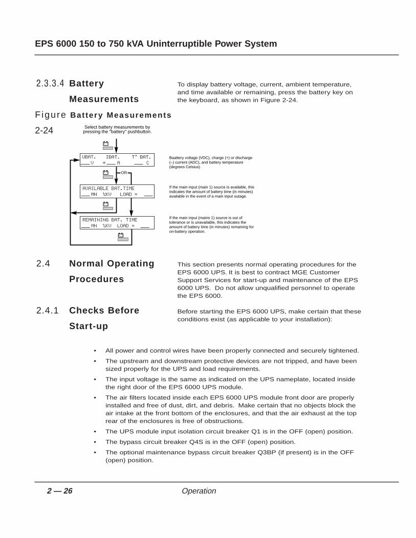
To display battery voltage, current, ambient temperature,and time available or remaining, press the battery key onthe keyboard, as shown in Figure 2-24.
F igure Battery Measurements
2-24
This section presents normal operating procedures for theEPS 6000 UPS. It is best to contract MGE CustomerSupport Services for start-up and maintenance of the EPS6000 UPS. Do not allow unqualified personnel to operatethe EPS 6000.
Before starting the EPS 6000 UPS, make certain that theseconditions exist (as applicable to your installation):
• All power and control wires have been properly connected and securely tightened.
• The upstream and downstream protective devices are not tripped, and have beensized properly for the UPS and load requirements.
• The input voltage is the same as indicated on the UPS nameplate, located insidethe right door of the EPS 6000 UPS module.
• The air filters located inside each EPS 6000 UPS module front door are properlyinstalled and free of dust, dirt, and debris. Make certain that no objects block theair intake at the front bottom of the enclosures, and that the air exhaust at the toprear of the enclosures is free of obstructions.
• The UPS module input isolation circuit breaker Q1 is in the OFF (open) position.
• The bypass circuit breaker Q4S is in the OFF (open) position.
• The optional maintenance bypass circuit breaker Q3BP (if present) is in the OFF(open) position.
2.4.1 Checks Before
Start-up
2.4 Normal Operating
Procedures
Select battery measurements by pressing the "battery" pushbutton.
UBAT. V
AVAILABLE BAT.TIME MN %KV LOAD =
IBAT.* A
T BAT. °
C
OR
REMAINING BAT. TIME MN %KV LOAD =
ı
ı
ı
ı
Baattery voltage (VDC), charge (+) or discharge (–) current (ADC), and battery temperature (degrees Celsius).
If the main input (main 1) source is available, this indicates the amount of battery time (in minutes) available in the event of a main input outage.
If the main input (mains 1) source is out of tolerance or is unavailable, this indicates the amount of battery time (in minutes) remaining for on-battery operation.
2.3.3.4 Battery
Measurements
2 — 26 Operation
EPS 6000 150 to 750 kVA Uninterruptible Power System

• The optional UPS isolation circuit breaker Q5N (if present) is in the OFF (open)position.
• The battery disconnect circuit breaker QF1 is in the OFF (open) position.
The following start-up procedure should be performedduring the initial start-up following installation of the system,and this sequence should be followed any time that the
EPS 6000 UPS is being restarted from an off condition (i.e., after the UPS has been powereddown by removing the upstream AC input power and opening all the circuit breakers of theUPS).
a. Apply power to Q4S by closing the upstream circuit breaker supplying Q4S.
b. Apply power to the UPS input by closing the upstream circuit breaker supplying themain AC input (mains 1).
c. Close the optional maintenance bypass circuit breaker Q3BP (if present). Power isnow available at the UPS output (the load is energized) via the bypass source.
d. Close the control or bypass circuit breaker Q4S. The static switch will come on-line; the fans will start.
e. Close the output isolation circuit breaker Q5N (if present).
f. Open the maintenance bypass circuit breaker Q3BP (if present). The load is nowsupplied via the bypass source.
Note that if your UPS configuration does not include the maintenance bypass option, start-up requires only closing Q4S to supply the bypass source to the attached load.g. Close the input isolation circuit breaker Q1. Verify that the following conditions
exist:
• The red “load not protected” LED is on
• The rectifier/battery charger automatically starts
If either condition is not present, there is a fault. Open Q1 and contact MGE CustomerSupport Services.h. Close the battery disconnect circuit breaker QF1. The batteries are now connected
to the rectifier/battery charger, and have begun charging.
i. If the UPS is not programmed for automatic restart, press the “inverter on”pushbutton. The green “load protected” LED will flash for about 3 seconds,indicating that the inverter is starting.
j. The UPS will automatically transfer the load to the UPS inverter output. The green“load protected” LED will turn on and remain on.
Because it is standard for the UPS module to be programmed for automatic restar t , the inver ter wil l automat ical ly star t a f ter the bat tery d isconnect circuit breaker QF1 has been closed.
IMPORTANT
2.4.2 Start-up
2 — 27Operation
User’s guide

k. Close the optional output distribution circuit breakers (if present).
After initial start-up of the system, normal operation shouldbe tested. At the minimum, the following tests should beperformed, as applicable to your installation:
• Emergency power off (EPO) test.
• Remote emergency power off (REPO) test (if applicable).
• Inverter start and stop.
• Battery transfer test.
• Maintenance bypass procedure.
This section presents procedures for shutting down theUPS cabinet under normal, emergency, overload, andmaintenance conditions.
During an emergency situation, such as a fire in the computer or electrical room, the UPS andall downstream devices can be instantly shut down by pressing the “emergency power off”(EPO) pushbutton on the front panel of the UPS cabinet, or by pressing the “remoteemergency power off” (REPO) optional pushbutton located within the room.
Pressing the EPO disconnects the attached load. The emergency power of f (EPO) is to be used during emergency situations only, where a hazard to personnel or equipment exists, such as during a f ire . DO NOT USE THE EPO TO TURN THE UPS ON OR OFF; fo l low the procedures l is ted in th is section for turning the inver ter on and off.
CAUTION
2.4.4.1 Emergency Shut-
down Using EPO
2.4.4 Shut-down
2.4.3 Checks After
Start-up
I f the transfer condit ions are not satisfied (bypass AC input sources is out of tolerance, or some other reason) , a forced transfer is required. Refer to Section 2.4.6, Forced Transfers.
NOTE
2 — 28 Operation
EPS 6000 150 to 750 kVA Uninterruptible Power System

The EPO or REPO pushbuttons should not be used for normal shutdown of the equipment;when activated, ground paths may be broken (depending on installation) and sensitive loadsattached to the UPS may lose safety ground connection.
To shut down the UPS, press the “inverter off” pushbuttonon the module front panel for 3 seconds. To restart, pressthe “inverter on” pushbutton. Note that the transfer will occur
only if the inverter is synchronized to the bypass; otherwise, a forced transfer is needed (seeSection 2.4.6).
To isolate the UPS for maintenance, or to transfer the loadto the bypass AC input source (if present), follow theprocedure that applies to your configuration.
This procedure assumes that the UPS is operatingnormally, with the attached load supplied via the UPSinverter.
1. Stop the inverter by pressing the “inverter off” pushbutton on the UPS front panelfor 3 seconds. The audible alarm will sound; silence the alarm by pressing theaudible alarm reset pushbutton on the hidden panel (see Section 2.2.3). If thetransfer conditions are not satisfied (bypass out of tolerance or other reason), aforced transfer is required; refer to Section 2.4.6, Forced Transfers.
2. Open the circuit breaker Q4S.
3. Open the battery disconnect circuit breaker(s) QF1.
4. Open the input isolation circuit breaker Q1.
The UPS is now isolated for maintenance. For complete protection, the upstream circuitbreaker(s) supplying the UPS should be opened, locked, and tagged while the UPS is beingserviced.
To restart the UPS after maintenance:
1. Close the input isolation circuit breaker Q1.
2. Close the circuit breaker Q4S. The UPS fans will start and the attached load willbe supplied via the bypass source.
Opening Q4S with the inver ter stopped in a UPS without maintenance bypass wi l l d isconnect the attached load.
CAUTION
2.4.5.1 Without
Maintenance
Bypass
2.4.5 Isolation for
Maintenance
2.4.4.2 Normal Shut-down
2 — 29Operation
User’s guide
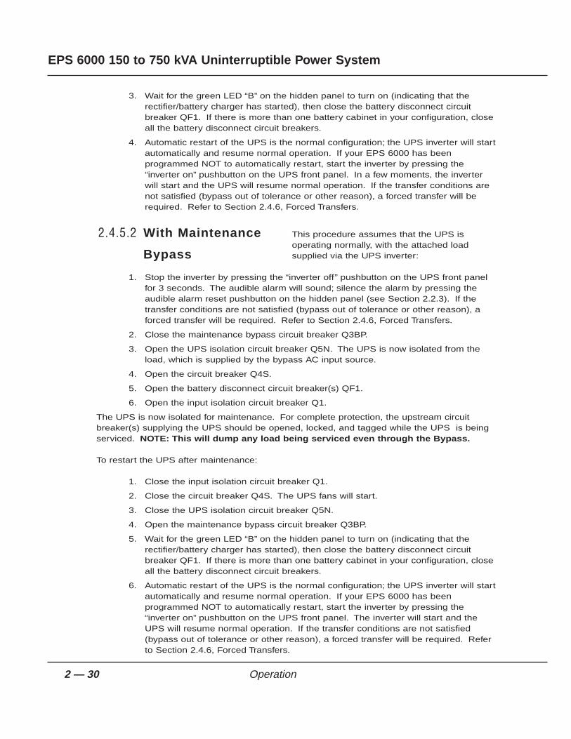
3. Wait for the green LED “B” on the hidden panel to turn on (indicating that therectifier/battery charger has started), then close the battery disconnect circuitbreaker QF1. If there is more than one battery cabinet in your configuration, closeall the battery disconnect circuit breakers.
4. Automatic restart of the UPS is the normal configuration; the UPS inverter will startautomatically and resume normal operation. If your EPS 6000 has beenprogrammed NOT to automatically restart, start the inverter by pressing the“inverter on” pushbutton on the UPS front panel. In a few moments, the inverterwill start and the UPS will resume normal operation. If the transfer conditions arenot satisfied (bypass out of tolerance or other reason), a forced transfer will berequired. Refer to Section 2.4.6, Forced Transfers.
This procedure assumes that the UPS isoperating normally, with the attached loadsupplied via the UPS inverter:
1. Stop the inverter by pressing the “inverter off” pushbutton on the UPS front panelfor 3 seconds. The audible alarm will sound; silence the alarm by pressing theaudible alarm reset pushbutton on the hidden panel (see Section 2.2.3). If thetransfer conditions are not satisfied (bypass out of tolerance or other reason), aforced transfer will be required. Refer to Section 2.4.6, Forced Transfers.
2. Close the maintenance bypass circuit breaker Q3BP.
3. Open the UPS isolation circuit breaker Q5N. The UPS is now isolated from theload, which is supplied by the bypass AC input source.
4. Open the circuit breaker Q4S.
5. Open the battery disconnect circuit breaker(s) QF1.
6. Open the input isolation circuit breaker Q1.
The UPS is now isolated for maintenance. For complete protection, the upstream circuitbreaker(s) supplying the UPS should be opened, locked, and tagged while the UPS is beingserviced. NOTE: This will dump any load being serviced even through the Bypass.
To restart the UPS after maintenance:
1. Close the input isolation circuit breaker Q1.
2. Close the circuit breaker Q4S. The UPS fans will start.
3. Close the UPS isolation circuit breaker Q5N.
4. Open the maintenance bypass circuit breaker Q3BP.
5. Wait for the green LED “B” on the hidden panel to turn on (indicating that therectifier/battery charger has started), then close the battery disconnect circuitbreaker QF1. If there is more than one battery cabinet in your configuration, closeall the battery disconnect circuit breakers.
6. Automatic restart of the UPS is the normal configuration; the UPS inverter will startautomatically and resume normal operation. If your EPS 6000 has beenprogrammed NOT to automatically restart, start the inverter by pressing the“inverter on” pushbutton on the UPS front panel. The inverter will start and theUPS will resume normal operation. If the transfer conditions are not satisfied(bypass out of tolerance or other reason), a forced transfer will be required. Referto Section 2.4.6, Forced Transfers.
2.4.5.2 With Maintenance
Bypass
2 — 30 Operation
EPS 6000 150 to 750 kVA Uninterruptible Power System
This section describes the normal transfer conditions andthe procedures to be followed when issuing forcedtransfers.
To transfer the load between the UPS module output andthe bypass AC input (mains 2) source without interruption,the following conditions must be satisfied:
• inverter output and bypass AC input phases must be in sync
• Bypass AC input voltage must be within 10% of nominal
• Bypass AC input frequency must be within a certain programmable tolerance ofnominal
Provided that both the UPS module output and bypass AC input sources meet theseconditions, uninterrupted transfers can take place. If these conditions are not met, transferscannot take place without interruption. A forced transfer is required.
Forced transfers require a power interruption to the load of 0.8 seconds. Before issuing aforced transfer command, be certain that the attached load can tolerate the brief outage. Thefollowing paragraphs describe the forced transfer procedures.
Start the inverter by pressing the “inverter on” button on thefront panel.
On the hidden panel, press the “security” key (Figure 2-7, )and hold it while pressing the “forced bypass to inverter” key(pushbutton #4). The load will be disconnected for 0.8seconds, then connected to the inverter.
On the hidden panel, press the “security” key (Figure 2-7)and hold it while pressing the “forced inverter to bypass” key(pushbutton #5). The inverter will stop and the load will bedisconnected for 0.8 seconds; then the load will beconnected to the bypass AC input source.
2.4.6.3 Forced Transfer
From Inverter to
Bypass AC Input
2.4.6.2 Forced Transfer
From Bypass AC
Input Source to
Inverter
2.4.6.1 Uninterrupted
Transfer Conditions
Opening Q4S with the inver ter stopped in a UPS without maintenance bypass wi l l d isconnect the attached load.
CAUTION
2.4.6 Forced Transfers
2 — 31Operation
User’s guide

2 — 32
EPS 6000 150 to 750 kVA Uninterruptible Power System
This section presents the most common alarm messagesthat appear on the LCD (the alphanumeric section of the“hidden” panel), and explains their meaning.
LOAD IS PROTECTEDUPS IS ON LINE
This is the normal display message. There are no alarms or problems, and the load is beingsupplied by the UPS inverter.
General alarms
LOW LEVEL ALARMUPS OK !
This message indicates that a problem requiring action has occurred. The load is still suppliedby the inverter. The problem is listed in the secondary alarm message (see below), asindicated by the flashing exclamation mark (!). The alarm message may be viewed bypressing the “alarm” pushbutton (!).
UPS INPUT FAILURELOAD ON BATTERY !
This message indicates that the main AC input (mains 1) has failed or is outside of tolerance,and power to the inverter is being supplied from the UPS battery system. The load is stillsupplied via the inverter.
REMAINING BAT. TIME__ MN %KW LOAD = __
This message is automatically displayed every five seconds when the UPS is on battery. Italternates with the previous message. The message provides an estimate of the availableremaining time on battery, based on the percentage of full rated load being supplied, the typeof battery, the battery temperature, and the battery age.
UPS LOW BATTERYSHUTDOWN IMMINENT !
This message indicates that the batteries have reached the “low battery shutdown” warninglevel. The user must take steps to prepare the load for shutdown (load shedding, file savingand computer shutdown, etc.). This message replaces the previous two messages when thebatteries are nearly depleted. When this message appears, there are only a few minutes ofbattery back-up time remaining.
UPS ALARMCALL SERVICE !
This indicates that the battery disconnect circuit breaker QF1 has been open or the inverterhas stopped and that service is required. The problem is listed in the secondary alarm
2.5 LCD Messages
Operation

message (see below), as indicated by the flashing exclamation mark (!). The secondary alarmmessage may be viewed by pressing the “alarm” pushbutton (!).
Secondary alarmsThe presence of these alarms is indicated by a flashing exclamation mark (!) on the generalalarm message. Press the “alarm” pushbutton to view these messages.
EMERGENCY SHUTDOWNREPO ON !
This message indicates that the UPS has been shut down because a remote emergencypower off (REPO) pushbutton has been pressed and is still closed.
LOAD ONBYPASS !
This message indicates that the load has been transferred to the bypass AC input (mains 2)source. The load is no longer protected.
BYPASS PROBLEMCHECK FREQUENCY !
This message indicates that the bypass AC input (mains 2) source is out of frequencytolerance. The inverter has switched to free-running mode. Transfer of the load from theinverter output to the bypass AC input source requires an interruption of power to the load.
BYPASS PROBLEMCHECK VOLTAGE !
This message indicates that the bypass AC input (mains 2) source is out of voltage tolerance.The inverter has switched to free-running mode. Transfer of the load from the inverter outputto the bypass AC input source requires an interruption of power to the load.
INDEPENDENT INVERTERFREQ. COMMAND ON !
This message indicates that the inverter has been set to free-running mode. The inverter isnot synchronized to the bypass AC input (mains 2) power source. Transfer of the load from theinverter output to the bypass AC input source requires an interruption of power to the load.
BYPASS TRANSFERLOCKOUT COMMAND ON !
This message indicates that the UPS has been set not to transfer from the inverter to thebypass AC input (mains 2) source. In the event of an inverter shutdown, the load will bedisconnected.
2 — 33Operation
User’s guide

BATTERY CABINETOVERTEMP. !
This message indicates that the ambient temperature of the battery is out of tolerance.
UPS INPUT PROBLEMCHECK FREQUENCY !
This message indicates that the main AC input (mains 1) frequency is out of tolerance. Therectifier/battery charger has shut down and the inverter is operating from its battery source.
UPS INPUT PROBLEMCHECK VOLTAGE !
This message indicates that the main AC input (mains 1) voltage is out of tolerance. therectifier/battery charger has shut down and the inverter is operating from its battery source.
CHARGER SHUTDOWNCOMMAND ON !
This message indicates that the rectifier/battery charger has been instructed to shut down, forexample during progressive (stepped) transfer to a motor-generator set.
INPUT KVA LIMITEDCOMMAND ON !
This message indicates that the rectifier/battery charger has been instructed to limit the powerdrawn from the main AC input (mains 1) source. This condition occurs, for example, when theload is being supplied by an undersized motor-generator set; the UPS battery source is calledupon to make up the difference.
BATTERY CURRENTLIMIT COMMAND ON !
This message indicates that the rectifier/battery charger has been instructed to limit thecharge current to the battery. Normal charge current to the battery will be supplied when thecommand is released. This condition occurs, for example, when the load is being supplied byan undersized motor-generator set.
QF1 BATTERY BREAKEROPEN !
This message indicates that the battery circuit breaker QF1 has been opened or has tripped.the load is no longer protected, since battery power is unavailable.
LOW BATTERY. . . !
This message indicates that the inverter has shut down, due to depletion of the battery’sstored energy.
2 — 34
EPS 6000 150 to 750 kVA Uninterruptible Power System
Operation

CHARGER OFF. . . !
This message indicates that the rectifier/battery charger has shut down.
CHARGER FAULTCALL SERVICE !
This message indicates that a fault has occurred in the rectifier/battery charger, and thatservice is required.
Q1 UPS INPUT CBOPEN !
This message indicates that the input isolation circuit breaker is open or has tripped. It mustbe closed for rectifier/battery charger start-up.
INVERTER OVERLOADCHECK P.F. AND KW
This message indicates that the inverter is in an overload condition, usually due to excessivereal power (kW) being drawn by the load. The flashing “KW” indicates that the operator shouldcheck the load real power. The inverter will keep supplying the load for a certain amount oftime depending on the overload level.
INVERTER FAULTCALL SERVICE !
This message indicates that a fault has occurred in the inverter, and that service is required.
INVERTER SHUTDOWNOVERLOAD > I MAX!
This message indicates that an overload greater than 1.5 times the full power rating of theinverter has occurred, and that the inverter has shut down.
INVERTER SHUTDOWNTHERMAL OVERLOAD A
This message indicates that an overload below 1.5 times the full power rating of the inverterhas occurred and that the inverter has shut down. The flashing “A” indicates that the operatorshould check the load current.
I LOAD > INCHECK LOAD A
This message indicates that the load power being drawn is greater than the UPS full loadrating. The flashing “A” indicates that the operator should check the load current. The inverteror static switch will keep supplying the load for a certain amount of time depending on theoverload level.
2 — 35Operation
User’s guide

TRANSFER FAULTCALL SERVICE !
This message indicates that a fault has occurred that affects the transfer of the load betweenthe inverter and the bypass source. Service is required.
PH OUT OF TOLERANCE !
This message indicates that there is an out of tolerance condition between the inverter andbypass AC input (mains 2) sources. Transfer of the load between the inverter and bypass ACinput will result in an interruption of load power.
Q4S BYPASS SWITCHOPEN !
This message indicates that the circuit breaker Q4S is open. Transfer of the load from theinverter to the bypass source is not possible.
Q5N UPS OUTPUT ISOL.SWITCH OPEN !
This message indicates that the optional UPS isolation circuit breaker Q5N is open. The loadis not supplied unless the maintenance bypass circuit breaker Q3BP is closed.
Q3BP MAINT. BYPASSSWITCH CLOSED !
This message indicates that the optional maintenance bypass circuit breaker Q3BP is closed.The system is set to maintenance bypass, and the load is supplied by the bypass AC inputsource (mains 2).
STATIC SWITCH O.L.EMERGENCY OFF !
This message indicates that the static switch has shut down following an overload condition,disconnecting the load.
BATTERY CHARGING !
This message indicates that the battery is being recharged.
INDEPENDENT INVERTERFREQUENCY !
This message indicates that the inverter is operating in free-running mode, and is no longersynchronous with the bypass AC input source (mains 2). Inverter frequency is stable within0.1 Hz, but transfer of the load to the bypass AC input source is not possible without an inter-ruption of power to the load.
2 — 36 Operation
EPS 6000 150 to 750 kVA Uninterruptible Power System
UPSTRANSFER LOCKOUT !
This message indicates that the load cannot be transferred from the inverter to the bypass ACinput (mains 2) source without interruption because the conditions for transfer without interrup-tion are not met (see Section 2.4.6.1), or because the inverter is operating in free-runningmode or in current limit, or because the UPS has been commanded not to transfer withoutinterruption, or because of an internal fault.
FAN FAILURECALL SERVICE !
This message indicates that a fan has failed, and that service is required. Because the fans ofthe rectifier/battery charger and the inverter are redundant, the load is still supplied by theinverter.
AUXILIARY CABINET FAULTCALL SERVICE !
This message indicates that there is a fault in an auxiliary cabinet, and that service is required.
CALL SERVICE FORBATTERY PM !
This message indicates that the battery may have reached its end of life (based on the ratedlifetime and the conditions of use).
MODULE NUMBER 1UNAVAILABLE
This message indicates that the core controller of the UPS is not sending data to the alphanu-meric display. The status of the UPS is still correctly indicated by the LEDs of the visible panel(see Section 2.2.1) and the hidden panel (see Section 2.2.3).
MODULE NUMBER 1FAULT
This message indicates that the core controller of the UPS is sending invalid data to thealphanumeric display. The status of the UPS is still correctly indicated by the LEDs of thevisible panel (see Section 2.2.1) and the hidden panel (see Section 2.2.3).
DISPLAY NUMBER 1UNAVAILABLE
This message indicates that the alphanumeric display is not operating properly. The status ofthe UPS is still correctly indicated by the LEDs of the visible panel (see Section 2.2.1) and thehidden panel (see Section 2.2.3).
2 — 37Operation
User’s guide

(this page left blank intentionally)
EPS 6000 150 to 750 kVA Uninterruptible Power System

This section describes maintenance of the EPS 6000 UPS,including safety instructions, preventive maintenance,
descriptions of replacement parts kits, and service.
IMPORTANT SAFETY INSTRUCTIONS FOR SERVICING BATTERIESA. Servicing of batteries should be performed or supervised by personnel knowledge-
able of batteries and the required precautions. Keep unauthorized personnel awayfrom batteries.
B. When replacing batteries, use the same model and manufacturer of batteries.
C. CAUTION — Do not dispose of battery or batteries in a fire. The battery mayexplode.
D. CAUTION — Do not open or mutilate the battery or batteries. Released electrolyteis harmful to the skin and eyes. It may be toxic.
E. CAUTION — A battery can present a risk of electrical shock and high short-circuitcurrent. The following precautions should be observed when working withbatteries:
1. Remove watches, rings, or other metal objects.
2. Use tools with insulated handles.
3. Wear rubber gloves and boots.
4. Do not lay tools or metal parts on top of batteries.
5. Disconnect charging source prior to connecting or disconnecting batteryterminals.
6. Determine if the battery is inadvertently grounded. If inadvertentlygrounded, remove the source of ground. Contact with any part of agrounded battery can result in electrical shock. The likelihood of suchshock will be reduced if such grounds are removed during installation andmaintenance.
The following preventive maintenance routines should beconsidered as the minimum requirements; your installationand site may require additional preventive maintenance toassure optimal performance from your installed EPS 6000
UPS and associated equipment. These routines should be performed twice a year (more oftenif required). we strongly recommend contracting MGE Customer Support Services forpreventive and remedial maintenance.
3.2 Preventive
Maintenance
3.1 Safety Instructions
3.0 Scope
3 — 1
Maintenance and Service

The technician or electrician performing preventive maintenance on the UPS must be familiarwith the indicators, controls, and operation of the UPS, as described in this manual.
a. Isolate and de-energize all EPS 6000 UPS equipment for all maintenanceoperations.
b. Ensure that all equipment is clean and free of loose dust, dirt, and debris. Theexterior of all enclosures may be cleaned with a mild solution of soap and water,lightly applied with a lint-free cloth.
c. Inspect the air intake and exhaust plates and clean as required. Verify that airflows freely through the equipment. Clean the air intake and exhaust plates, andthe enclosure interior, with a vacuum cleaner.
d. The EPS 6000 UPS is equipped with air filters that should be changed at regularintervals. Inspect the filters regularly to determine how long the filters will last inyour installation.
e. Initiate the start-up procedure, as described in Section 2.4.1.
f. Test the main operating sequences as applicable to your equipment configurationand installation.
There are no user replaceable parts inside the EPS 6000 UPS.
Three levels of replacement parts are available for the EPS 6000 UPS. The three levels aredesignated A, B, and C. The level that you should keep on hand for your installation will varydepending on the type of maintenance planned on site, and the configuration of your UPSsystem. Having replacement parts on hand will prevent any unacceptable delays (due to timeinvolved obtaining spare parts) during critical periods, such as system start-up. Any itemsused during start-up will be replaced by MGE at no charge. Contact MGE Customer SupportServices for specific recommendations. A description of each level is provided below:
Level Description
A This level of replacement parts consists of consumable items, specifically fuses and airfilters. It is recommended to have these items on hand during installation of the UPSsystem, including initial start-up.
B This level of replacement parts is recommended when the user can tolerate short-dura-tion UPS down-time to obtain replacement parts in the event of a major UPS failure. Thislevel of replacement parts consists of consumable items, specifically fuses, air filters, aninverter leg, and the most critical circuit board assemblies.
C This level of replacement parts is recommended when the user can tolerate only a mini-mum of down-time in the event of a major UPS failure. This level of replacement partsconsists of consumable items, specifically fuses, air filters, an inverter leg, and a com-plete set of circuit board assemblies.
Should you encounter a problem in the operation of a UPSand need MGE UPS Systems, Inc. to service your product,please take into account the following recommendations.
3.4 Troubleshooting
and MGE Servicing
3.3 Replacement Parts
3 — 2 Maintenance and Service
EPS 6000 150 to 750 kVA Uninterruptible Power System

To the extent that you feel comfortable with the unit, leave it in its current state, make a recordof the display lights and alarm messages and call either your local MGE Field Engineer orMGE’s Customer Support Services at 1-800-438-7373 for assistance. Leaving the unit in itscurrent state will enable MGE’s field engineers to troubleshoot your product and bring it backon line more easily.
If you are not comfortable with the current status of the unit, you may want to take thefollowing actions (listed by order of increasing impact on ease of troubleshooting):
1. If the audible alarm is active, reset it by pressing the audible alarm reset button(the second button from the left on the lower hidden panel as shown in Figure 2-7).
2. Stop the inverter (see Section 2.4.4.2 for normal shutdown and Section 2.4.6.3 forforced shut down).
3. Put the load on maintenance bypass by closing the maintenance bypass circuitbreaker Q3BP, opening the isolation circuit breaker Q5N, and opening the circuitbreaker Q4S.
4. Open the battery circuit breaker(s) QF1.
5. Reset the alarms by pressing the fault log clear button (the left most button on thelower hidden panel as shown in Figure 2-7).
6. Open the input isolation circuit breaker Q1 or the upstream circuit breaker feedingQ1. NOTE: This will dump all loads serviced by a single-feed UPS withmaintenance bypass.
After taking these steps, make a record of the display lights and alarm messages and call yourlocal MGE Field Engineer or call 1-800-438-7373 for assistance.
3 — 3Maintenance and Service
User’s guide

(this page left blank intentionally)
EPS 6000 150 to 750 kVA Uninterruptible Power System

Symbols
¶ Used to reference paragraph headings that are listed in the table ofcontents.
/ Used to represent “and/or.”
% Percent; of each hundred.
° F. Degrees Fahrenheit.
° C Degrees Celsius.
@ At.
± Plus or minus.
# Number.
Ø Phase.
Ω Ohms.
2nd Second.
A, B, C Normal sequence of phases (clockwise) in three-phase power.
AC or ac Alternating current.
Alphanumeric display The LCD display above the hidden panel (behind the drop-down cover) on
the UPS module and the SSC.
Ambient air temperature The temperature of the surrounding air.
Ambient noise The noise level of the environment.
Attached load The load attached to the UPS output, such as a computer system ormanufacturing system.
Audible alarm A buzzer, located behind the front panel on the UPS module and the SSC,that sounds when alarm conditions occur.
AWG American Wire Gauge, formerly Brown & Sharp gauge.
g — 1
Glossary

B or BAT.or BATT. Battery.
Breaker Circuit breaker.
British Thermal Unit A unit of heat equal to 252 calories (see BTU).
BTU or Btu British thermal unit. Defined as the amount of energy required to raise thetemperature of 1 pound of water by 1° F.
BYP Bypass.
BYPASS Maintenance bypass; wrap-around manual maintenance bypass using theoptional bypass circuit breaker Q3BP in conjunction with circuit breakerQ4S and isolation circuit breaker Q5N.
Bypass AC input Mains 2.
Calorie A unit of heat. One calorie is the amount of energy required to raise thetemperature of one gram of water by one degree Celsius.
Carrier The company or individual responsible for delivering goods from one areato another.
CB Circuit breaker.
Conduit A flexible or rigid tube surrounding electrical conductors.
C.S.S. Customer Support Services.
CT Current transformer.
Curr. Current.
Current rating The maximum current that a piece of electrical equipment is designed tocarry.
DC or dc Direct current.
Earth ground A ground circuit that has contact with the earth.
Electrician Refers to an installation electrician qualified to install heavy-duty electricalcomponents in accordance with local codes and regulations. Notnecessarily qualified to maintain or repair electrical or electronic equipment.Compare to technician.
EPO Emergency power off.
g — 2 Glossary
EPS 6000 150 to 750 kVA Uninterruptible Power System

Free running Indicates that the inverter frequency is stable and independent of thebypass AC input (mains 2) frequency.
FREQ Frequency.
Fusible Capable of being melted with heat.
GND Ground
Hz Hertz, a measure of frequency; one cycle per second equals one Hertz.
I Current.
Input branch circuit The input circuit from the building power panel to the equipment.
Inverter An electrical circuit that generates an AC sinewave output from a DC input.
kVA Kilovolt-Ampere; a measure of apparent power.
kW Kilowatt; a measure of real power.
LCD Liquid-crystal display.
LED Light-emitting diode.
LEG or Leg Inverter leg.
Load protected The attached load is being supplied by the UPS module inverter output,and the battery is available in the event that incoming (utility) power is lost.
Load not protected The attached load is being supplied, but the battery system is unavailable.
Low battery shutdown The battery has reached the lowest permitted operating voltage, and the
inverter has shut down (disconnecting the load) to protect the battery fromdamage due to further discharge.
Mains or mains 1 Main AC input source.
Mains 2 Bypass AC input source.
MAX Maximum.
MBC Optional maintenance bypass cabinet that attaches to the SSC (in sharedsystems).
g — 3Glossary
User’s guide

MCM Thousand circular mil; standard wire sizes for multiple stranded conductorsover 4/0 AWG in diameter. M is from the Roman numeral system; it is thesymbol for 1,000.
MG Motor-generator set.
MGE MGE UPS Systems, Inc.
module Refers to an EPS 6000 UPS module (rectifier/battery charger, inverter, andattached battery cabinet).
MOV Metal-oxide varistor.
NEC National electrical code.
NFPA National fire protection association.
NO. or No. Part number.
OSHA Occupational safety and health act.
OF Over-frequency.
On-battery operation The attached load is being supplied by the stored energy in the battery
system.
OV Over-voltage.
Packing list The list of articles included in a given shipment.
P.F. Power factor.
Q1 UPS input isolation circuit breaker.
Q3BP Optional maintenance bypass circuit breaker (in single-module UPSsystem); optional maintenance bypass circuit breaker in MBC cabinet (inshared systems).
Q4S Control or bypass circuit breaker (in single-module UPS systems); user-supplied bypass AC input circuit breaker supplying the SSC (in sharedsystems).
Q5N Optional UPS isolation circuit breaker (in single-module UPS systems);UPS module isolation circuit breaker (in shared systems); optional SSCisolation circuit breaker (in MBC).
QF1 Battery disconnect circuit breaker.
g — 4 Glossary
EPS 6000 150 to 750 kVA Uninterruptible Power System
Remote emergency power off A switch used for shutting down electrical equipment from a location away
from the equipment.
REPO Remote emergency power off.
SCR Silicon-controlled rectifier.
Security bypass (key) Pushbutton on the hidden panel (UPS modules and SSC) allowing forced
transfers and other commands to be issued. The security key pushbuttonmust be held down while the desired function is executed.
SEQ Sequence.
Shipping damage Any damage done to an article while it is in transit.
Shipping pallet A platform on which articles are fixed for shipping.
Specific gravity The ratio of the weight of a given volume of substance (such as electrolyte)to that of an equal volume of another substance (such as water) used as areference.
SSC Static switch cabinet (in shared systems).
Sync or synch Synchronization.
Technician Refers to an electronic technician qualified to maintain and repair electronicequipment. Not necessarily qualified to install electrical wiring. Comparewith electrician.
Test connector DB-9 type connector on the hidden panel (UPS modules and SSC) allowingan MGE Customer Support Services technician to access programmableand diagnostic features of the system.
U Voltage.
UF Under frequency.
UL Underwriters Laboratories, Inc.
UPS Uninterruptible power system.
UV Under voltage.
VAC Volts of Alternating current.
Vb Battery voltage (in volts DC).
g — 5Glossary
User’s guide

VDC Volts of direct current.
Via By way of.
VPC Volts per cell, the measure of the electrical potential of a storage cell, suchas a battery.
XFMR Transformer.
g — 6 Glossary
EPS 6000 150 to 750 kVA Uninterruptible Power System

Reorder form
to order additional copies of this document, or to report any errors,omissions, or other problems you have experienced.
NAME ______________________________________________________________________
COMPANY __________________________________________________________________
STREET ADDRESS ___________________________________________________________
CITY __________________________________ STATE ___________ ZIP ______________
I would like to order ________ (quantity @ $50.00 each) additional copies of the:
EPS 6000 UPS150 to 750 kVA User’s Guide
86-130033-00
I would like to report the following problems with this document:
____________________________________________________________________________
____________________________________________________________________________
____________________________________________________________________________
____________________________________________________________________________
____________________________________________________________________________
____________________________________________________________________________
____________________________________________________________________________
____________________________________________________________________________
Use this form
1660 Scenic Avenue
Costa Mesa, CA 92626


Nothing will stop you now ™
1660 Scenic Avenue, Costa Mesa, California 92626 • (714) 557-1636 • www.mgeups.com