Embed Size (px)
Citation preview
I
I
1
I
I
1
MIL-HDBK-2164A19 June 1996SUPERSEDINGMIL-HDBK-2164(SH)16 January 1996
DEPARTMENT OF DEFENSEHANDBOOK
ENVIRONMENTM-J STRESS SCREENINGPROCESS
FOR
ELECTRONIC EQUIPMENT
THIS HANDBOOK IS FOR GUIDANCE ONLY. DO NOT CITE THIS DOCUMENT
AS A REQUIREMENT.
AMSC NIA AREA RELI
,., .._. -.. —..
MIL-HDBK-2164A
FOREWORD
1. This handbook is approved for use by all Departments and Agencies
of the Department of Defense (DoD)
2. This handbook is for guidance only. This handbook cannot be
cited as a requirement. If it is, the contractor does not have to comply.
3. The current emphasis on quality, reliability and hardware design
integrity has resulted in efforts to provide a sound and inherently
reliable design. The increased complexity and density of packaging of
contemporary electronic equipment amplifies the ever present problems of
detecting and correcting latent manufacturing defects. The occurrence of a
malfunction incurs extremely high maintenance costs after the equipment has
been deployed. It is also important that laboratory testing be extensive
enough to prevent failure that would result in loss of life or mission.
4. This handbook provides guidelines that will help in the
Environmental Strese Screening (ESS) of electronic equipment so that latent
defects may be located and eliminated before the equipment is accepted. It
has been written in compliance with the DoD Acquisition Reform Initiatives
(ARI), Single PrOCeSe Initiative (sPI), and the latest series of DoD
acquisition directives.
5. Beneficial connnents (recommendations, additions, deletionfi) and
any pertinent data which may be of use in improving thie document should be
addressed to: Commander, Naval Sea Systems Conmnand, SEA 03R42, 2531
Jeff erson Davis Highway, l+rlington, VA 22242-5160, by using the self-
addressed Standardization Document Improvement Proposal (DD Fonn 1426)
appearing at the end of this document or by letter.
. .
ii

. .
MIL-HDBK-2164A
cONTENTS
~ . . . . . . . . . . . . . . . . . . . . . . . . . . . . . . . . . . . . . . . . . . . . . . .
1.
1.1 Purpose ............................................
1.2 Application to products ............................
1.2.1 Large, heavy items .................................
1 .2.2 Contractual responsibility considerations. .........
2.
2.1 General ............................................
2.2 Government documents ...............................
2 .2.1 Specif icat ions, standarda, and handbooks ............
2.2.2 Other Government documents, drawings, and
publications .......................................
2.3 Non-Governm6nt publications ........................
2.4 Order of precedence ................................
3.
3.1 De finitions ........................................
3.2 Acronyms used in this handbook. ....................
4.
4.1
4.2
4 .2.1
4 .2.1.1
4.2. 1.2
4.2.1.3
4.2 .1.4
4 .2.1.5
4 .2.2
4.3
4 .3.1
4.3.2
4 .3.3
4.4
4.5
4.5.1
4 .5.1.1
4 .5.2
General ............................................
Screening conditions ...............................
General environmental guidelines. ..................
Standard ambient ...................................
Controlled ambient .................................
Thermal screening tolerances .......................
Vibration screening tolerances. ....................
Time ...............................................
Accuracy of screening instrumentation calibration. .
Screening facilities ...............................
Screening chamber ..................................
Vibration apparatus ................................
Quality of air for supplementary cooled equipment. .
General instrumentation guidelines. ................
Vibration screening guidelines. .............. ....
Screening fixture ..................................
.Fixture checkout ...................................
Control excitation ........................”.........
iii
EAGE
ii
1
1
1
2
2
3
3
3
3
4
4
4
4
4
6
-7
7
7’
9
9
9
9
10..
10
10
10
10
11
11
11
12
12
13
13
_. .._,
MIL-HDBK-2164A
CONTENTS
4.6
4.7
4 .7.1
4 .7.2
4 .7.3
4.8
Performance monitoring guidelines. ................
Failure reporting, analysis, and correction action
system (FRACAS )....................................
Failure during pre defect-free screening. .........
Failures during defect-free screening. ............
Rescreening .......................................
Sampling ..........................................
5.
5.1
5.1.1
5. 1.1.1
5.1.2
5. 1.2.1
5. 1.2.1.1
5 .1.2.1.2
5.1.2.2
5. 1.2.2.1
5.1.2 .2.2
5.2
5.2.1
5.2.2
5.2 .2.1
5.2 .2.2
5.2.3
5.2.3.1
5.2 .3.1.1
5.2 .3.1.2
5.2 .3.2
5.3
Environmental stresses. ...........................
Random vibration spectrum. ........................
Applied axis detemination. .......................
Temperature cycling ...............................
Thermal survey ....................................
Procedure for ambient-cooled equipment. ...........
Procedure for supplementally cooled equipment. .....
Thermal screening ...................................
Ambient cooled equipment.. ........................
Supplementally cooled equipment. ..................
Total ESS program .................................
Documentation ................................. ....
Individual tests ..................................
Examination of product. ........................ ..
Initial operational test ..........................
Environmental Screening. ..........................
Fixed duration pre defect-free (PDF) screening. ...
Vibration .........................................
Thermal cycling ...................................
Defect-free (DF) screening ........................
Final functional operational tefit.................
6. ~
6.1 Intended use ......................................
6.2 Subject term (keyword) listing ...................
1. Screen Development Process. .......................
2. Environmental Stress Screening Constituents. ......
3. Random Vibration Spectrum. ........................
PAGE
13
13
13
13
14
14
14
14
14
14
15
17
17
18
19
19
19
20
20
20
20
21
21
21
21
21
22
22
22
22
22
2
8
15
iv
4
A-1
A-I.
A-II.
c-I.
A
B
c
MIL-HDBK-2164A .
CONTE~S
Temperature Cycling Profile for Ambient Cooled and
Supplementary Cooled Equipment. ...................
ESS Characteristics Curve .........................
Values of PA for Various a and TPDF = TDF. .........
Probability of Rejections Due to Random Failure
fOr VariOus Values Of El~..........................
ESSBenefits to Management ........................
ESS screening duration, reduced screening and
sampling ..........................................
ESS troubleshooting plan. .........................
Navy program management guidance. :.. ..............
PAGE
16
25
28
28
35
23
30
32
v
..—.— —___
MIL-HDBK-2164A
1. SCOPE
1.1 OlzQcEe. This handbook provides guidelines for Environmental
Stress Screening (ESS) of electronic equipment, including environmental
screening conditions, durations of exposure, procedures, equipment
operation, actions taken upon detection of defects, and screening
documentation. These guidelines provide for a uniform ESS process that may
be utilized for effectively disclosing manufacturing defects in electronic
equipment caused by poor workmanship and faulty or marginal parts. It will
also identify design problems if the design is inherently fragile or if
qualification and reliability growth tests were too benign or not
accomplished. The most common stimuli used in ESS are temperature cycling
and random vibration. A viable ESS prcgram” must be dynamic; the screening
program must be actively managed, and tailored to the particular
characteristics of the equipment being screened. It should be noted that
there are no universal screens applicable to all equipment.
ESS is part of a viable engineering development, manufacturing corrective
action and overhaul process rather than a test in the normal accept/reject
8ense. Guidance in developing a screen can be found in figure 1. Those
participating in the effort, including the contractor should never be led
to believe that a “failure” is bad and’would be held against them. ESS is
intended to stimulate defects, not to simulate the operating environment,
and therefore, factory failures are encouraged. The root causea of ESS
failures need to be found and corrected before there is a complete process.
This handbook cannot be cited as a requirement. If it ia, the contractor
does not have to comply.
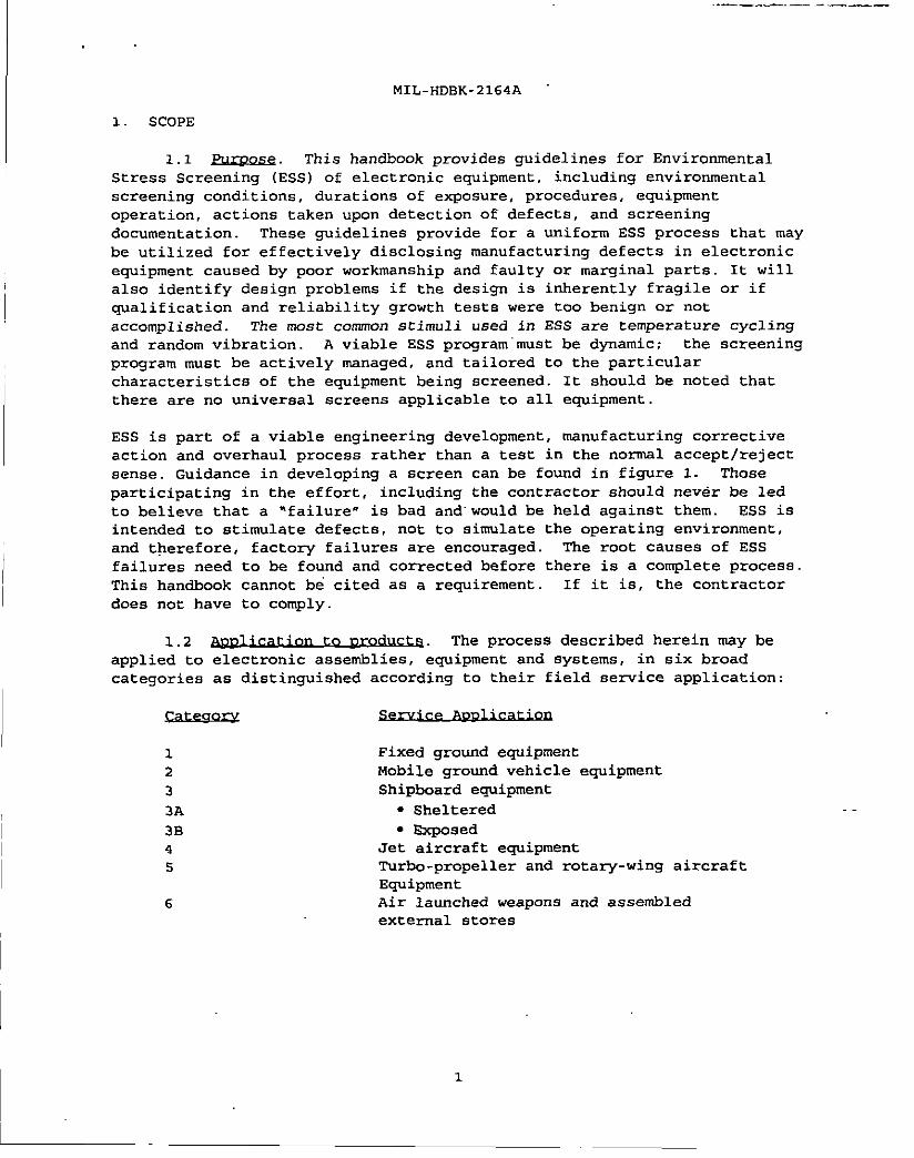
1.2 The process described herein msy be
aPPlied to electronic assemblies, eqUiPment and systems, in six broad
categories as distinguished according to their field service application:
1
2
3
3A
3B
4
5
6
Fixed ground equipment
Mobile ground vehicle equipment
Shipboard equipment
● Sheltered
● Exposed
Jet aircraft equipment
Turbo-propeller and rotary-wing aircraft
Equipment
Air launched weapons and assembled
external stores
1

.- .— .-. . . . ..-— -— ——.
MIL-HDBK-2164A “
FEEDBACK
START r I
I t I
@li=l-i=l-@’l
B&REBUILDOR RUN SCREEN INCREASE
NEW MULTIPLE SCREENPRODUCT TIMES SEVERITY
1.2.1 when applying these guidelines to large,
heavy items, the following should be considered:
. Potential fatigue of the item
● Adequate environmental inputs
. Availability of suitable environmental generation
facilities
. Technical validity of screening at lower assembly levels, i.e. ,
drawers, chassis
1.2.2 Navy-approved
detailed screening procedures are used to verify contractual requirements
2
. . . . .
. .
MIL-HDBK-2164A
I
Acquisition authorities are cautioned from advising contractors on how to
obtain desired results. They should confine the contractual requirements
to performance requirements, rather than dictating the manufacturing
method. Appendix A contains guidance concerning screening duration,
reduced screening and sampling. Appendix B covers some considerations
useful in formulating a troubleshooting plan to address ESS failures, while
Appendix C contains guidance. that will assist the Navy program manager in
understanding Environmental Stress Screening, including the Department of
the Navy Single Process Initiative, and provides guidance in the
preparation of contractual acquisition documentation.
2. APPLICABLE DOCUNSNTS
2.1 General. The documents listed below are not necessarily all of
the documents referenced hexein, but are the ones needed in order to fully
understand the informat ion provided by this handbook.
2 .2.1 and The f01lowing
standard and handbook form a part of this document to the extent’ specified
herein. Unless otherwise specified, the issues of these documents are
those listed in the issue of the Department of Defense Index of
Specifications and Standards (DODISS) and supplement thereto.
STANDARD
DEPARTMENT OF DEFENSE
klIL-STD-1235 - Single- and Multi-Level Continuous
Sampling Procedures and Tables for
Inspection by Attributea Functional
Curves of the Continuous Sampling Plans
HANDBOOK
DEPARTMENT OF DEFBNSE
MIL-H32BK-781 - Reliability Test Methods, Plans, and
Environments for Engineering
Development, Qualification, and
Product ion
(Unless otherwise indicated, copies of federal and military
specifications, standards, and handbooks are available from the
Standardization Documents Order Desk, Bldg. 4D, 700 Robbins Avenue,
Philadelphia, PA 19111-5094. )
3

MIL-HDBK-2164A
2 .2.2 Qtb.er GOV~ . and The
following other Government documents, drawings, and publications form a
part of this document to the extent specified herein.
TRI-SERVICE TECHNICAL BRIEF 002-93-08 - Environmental Stress
Screening Guidelines
(Application for copies should be addressed to The Office of the
Assistant Secretary of the Navy (Research, Development, and Acquisition)
Product Integrity, 2211 Jefferson Davis Highway, Arlington, VA 22244. )
2.3 ~. The following document (s) form a
part of this document to the extent E.pecified herein. Unless otherwise
specified, the issues of the documents which are DoD adopted are those
listed in the issue of the DoDISS, and supplement thereto.
AMERICAN NATIONAL STANDARDS INSTITUTE
ANSI/NCSL Z540-1 - General Requirements for Calibration
Laboratories and Measuring Test Equipment
(Application for copies should be addressed to the Institute of
Electrical and Electronics Engineers, Inc. , 445 Hoes Lane,
P.O. Box 1331, Piscataway, NJ 08855-1331. )
.,. s,.LUIE ur ILL. vuw,.mm.iau =GLm. w7,a i.c.a,
Environmental Stress Screening Guidelines, 1981
Environmental Stress Screening Guidelines for
Assemblies, March 1990
Environmental Stress Screening Guidelines for
Parts, September 1985
(ADDlication for couies should be addressed to the Institute of. .Environmental Sciences, 940 East Northwest Highway, Mt. Prospect, IL 60056-
3444)
2.4 ~. In the event of a conflict between the
text of this document and the references cited herein, the text of this
document takes precedence. Nothing in this document, however, eupersedee
aPPliC?dIle lawS and regulations unless a specific exemption has been
obtained.
3. DEFINITIONS AND ACRONYMS
3.1 ~. Definitions appl cable to this handbook are:
4
.,.
MIL-HDBK-2164A
Assembly/Module -
Chamber
Defect
Environmental -
Stress Screening
ESS failure
A number of parts joined together to perform a
specific function and capable of disassembly,
e.g. , a printed circuit board.
Cabinet in which hardware is placed in order to
apply stress to it.
The causative element that results in a failure.
ESS of a product is a process which involves
the application of one or more specific types of
environmental stresses for the purpose of
precipitating to hard failure, latent,
intermittent, or incipient defects or flaws which
would otherwise cause product failure in the use
environment. The stress may be applied either in
combination or in sequence on an accelerated
basis, but within product design capabilities.
Failures occurring in the defect-free screening
that cannot be classified as non-ESS failures as
defined below. ESS failurea include those due to
defective manufacturing processes and defective
components.
Nfyr.E: In the event that several component parts of the same type fail
during the screening, each one sliould be considered a separate ESS failure,
unless it can be shown
Latent Defect
that one failure caused one or more of the others.
k inherent or induced weakness, not detectable
by ordinary mesns, which will either be
precipitated to early failure under environmental
stress screening conditions or eventually fail in
the intended use environment.
Levels of product Definitions relating to levels of product are as
specified:
a. h item which can be
removed and replaced within the end item,
such as a weapon replaceable assembly (NRA)
or line replaceable unit (LRU)
b. Sy,aLQU. A ‘group of electronic LiIIits,
interconnected, which provide a specific
funct ion, for example, a radar system or
navigation system.
Non-ESS failure - The following failures are non-ESS failures:
— ..
,!
Part
Thermal Survey -
Vibration Survey
a.
b.
c.
d.
e.
f.
9.
MIL-HDBK-2164A .
Failures directly attributable to improper
installation in the screening facility.
Failures of screening instrumentation or
monitoring eguipment (other than the Built
In Test (BIT) function) , except where it is
part of the delivered item.
Failures resulting from operator error in
setting up, or in screening the equipment.
Failures attributable to an error in, or
interpretation of, the screening procedures.
Dependent failures.
Failures occurring during repair.
Failures clearly attributable to the
environmental generation screening equipment
overstress condition.
One piece, or two or more pieces joined tngether
which are not normally subject to disassembly
without destruction of designed use. Parts,
components, and devices are synonymous
The measurement of thermal response
characteristics at points of interest within an
equipment when temperature extremes are applied
to the equipment.
The measurement of vibration response
characteristics at points of interest within an
ecluiPment when vibration excitation is applied to
the equipment.
3.2
a.
b.
c.
d.
e.
f.
9.
h.
1.
j.k.
1.
ARI
BIT
COTS
ESS
FAR
FRACAS
IRIG
LRu
MTBF
NDI
SPC
Acquisition Reform Initiatives
Built In Test
Commercial-Off -The-Shelf
Environmental Stress Screening
Federal Acquisition Regulations
Failure Reporting and Corrective Action System
Inter-Range Instrument Group
Line Replaceable Unit
Mean Time Between Failure
Nondevelopmental Item
Pre Defect-Free
Statistical Process Control
. .
6

.—. .— . ..-____ _—
MIL-HDBK-2164A
m. WRA Weapon Replaceable Assembly
4. GENERAL GUIDELINES
4.1 Qencral. ESS screenings are usually accomplished
with the guidelines of MIL-WDBK-781 to ensure that hardware
in accordance
is free of
manufacturing defects Design and manufacturing practice calls for the
application of environmental stress screening to,
● All material acquisitions that include electrical, electronic,
electro-optical, electromechanical or electro-chemical
component in program definition and risk reduction,
engineering and manuf act uring development, and production,
fielding/deployment, and operational phaSeB
● Reprocurements and to the procurement of spare and repair parts
where the cost of ESS implementation can be amortized
economically
. Depot overhaul programs where opportunities exiBt for
substantial cost Bavings
. Nondevelopmental items such as commercial-off-the-shelf (NDI-
COTS) snd domestic or foreign military (NDI-Military) items
only to the extent ESS was implemented and documented during
the previous product ion
. Systems, equipment, and spares that have been specifically
designed to receive ESS
4.2 The following conditions should be
required for all ESS :
a. ESS may be applied at any manufacturing level, from piece parts
to end items. It is intended to screen defectB in a manner that is not
harmful to properly manufactured material. Hardware proven to be too
fragile may be excluded because screening environments may be too harmful,
but rationale for exclusion should be included in appropriate documental ion --
such as a stress screening plan.
b. All screening should be accomplished in accordance with the
applicable guidelines specified herein.
c. There should be evidence of quality control acceptance of all
reguired inspection or test activity prior to the start of any contractual
environmental stress screening, and at each time maintenance is performed.
d. All testing should be completed prior to packaging the equipment.
-1
-— .- . ..- -, .--— —- . . . . . . . .. . . . ——— . . .
. .
MIL-HOBK-2164A
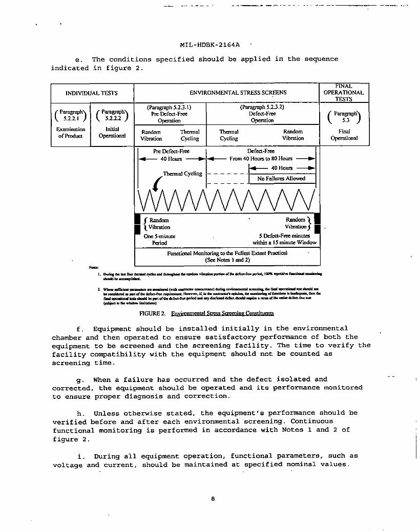
e. The conditions specified should be applied in the sequence
indicated in figure 2.
FfNN.INDIVIDUALTESTS ENVIRONMENTALSTRESSSCREENS OPERATIONAL
lTiSTS
(p=’) (p=’) ‘~?!g%~)
(-’ 5.2.2.2)Dercd-Fme
m. (pF’)Ikmninalio. Mid
Rondo. Themal Tlmmml REndom FindofF70d”ct op@iOn@J
vibration cycling Cydiig Vibmdon Opcmliomd
IIPmOefti-Fme
-1
Oefed-Fmz
~ 40Hours ~ Fmm 40Hounto80How
& 40HoumAII I------===l
‘rhR’mnlcycling––––––-
/
f. Equipment should be installed initially in the environmental
chamber and then operated to ensure satisfactory performance of both the
equipment to be screened and the screening facility. The time to verify the
facility compatibility with the equipment should not be counted as
screening time.
9. When a failure has occurred and the defect isolated and..
corrected, the equipment should be operated and its performance monitored
to ensure proper diagnosis and correction.
h. Unless otherwise stated, the equipment’s performance should be
verified before and after each environmental screening. Continuous
functional monitoring is performed in accordance with Notes 1 and 2 of
figure 2.
i. During all equipment operation, functional parameters, such as
voltage and current, should be maintained at specified nominal values
MIL-H13BK-2164A
j. The BIT capabilities of the equipment should be
maximum extent to aid in the performance monitoring. BIT
sole means of monitoring performance.
utilized to the
should not be the
k. Anticipation of failure should not be justification for
maintenance; for example, if an output is observed to be degrading but is
still within specification limits, no replacement or adjustment may be
permitted unless such adjustments are normally made manually.
1. Failures detected during screening should be counted as if they
occurred in the defect-free period if the equipment used to monitor the
performance characteristics during the screening was not capable of
detecting that failure. Refer to figure 2, Notes 1 and 2.
4 .2.1 Unless otherwise specified,
measurements and screenings should be made at the conditions in 4 .2.1.1
through 4.2.1.5.
4 .2.1.1 Ambient measurement and checks (e.g.,
pre - and post-screening) are conducted at room ambient conditions as
follows :
Temperature: 250C i 10°C (77°F i 18°F)
Relative humidity: Uncontrolled room ambient
Atmospheric prefisure: Uncontrolled site pressure
4 .2.1.2 Nhen the ambient conditions must be
closely controlled, the following should be maintained:
Temperature: 23°C f 2°C (73°F * 3.6°F)
Relative humidity: 50 percent * 5 percent
Atmospheric Pressure: Ideal: 96.45kPa (Range 86.45-162.45)
Ideal: 725 mmHg (Range 655-775)
Ideal: 28.5 inHg (Range 25.5-30.5)
4 .2.1.3 The screened item should be
totally surrounded by an envelope of air except at necessary support
points. The temperature gradient throughout this envelope, which is
measured close to the screened item, should be within + 2°C (*3.6“F) of the
screening temperature and not exceed 1‘C per meter or a maximum of 2.2 “C
total with equipment nonoperating.
9
.—
. .
MIL-HDBK-2164A
4 .2.1.4 ~. The acceleration power
spectral density of the screening control signal should not deviate from
the specified guidelines by more than *3 d33over the entire test frequency
range between 20 Hz and 1,000 Hz and should not deviate by more than i6 dB
in the screening frequency range between 1,000 and 2,000 Hz. However,
deviations of -6 dB in the screening control signal may be granted for
frequencies greater than 500 Hz due to fixture resonance, screened item
re50nance, or facility limitations. The cumulative bandwidth over which the
reductions are allowed cannot be greater than 100 Hz between 500 Hz and
1,000 Hz and 300 Hz between 1,000 Hz and 2,000 Hz. In no case should the
acceleration power spectral density be more than -6 dB below the specified
guidelines No deviation should be granted for frequencies below 500 Hz.
Tolerance levels in terms of dB are defined “as:
wCU3.1010CJ ,0-.-.!
w,where
WI - measured acceleration power spectral density in g2/Hz units
V/. - specified level in g2/Hz units
Confirmation of these tolerances should be made by the use of an analysis
system with the following characteristic:
20 to 200 Hz 25 HZ
200 to 1000 Hz 50 Hz
1000 to 2000 Hz 100 Hz
4.2 .1.5 Xi.OE. Elapsed time should be measured with an accuracy of
*1 percent.
4 .2.2 The
accuracy of instruments and screening equipment used to control or monitor
the screening parameters should be calibrated in predetermined intervals
and then verified prior to and following each screening. Xi 1 instruments.
and screening equipment used in conducting the screenings specified herein
should be calibrated to national standards, such as ANSI/NCSL Z540-1.
4.3 Screening facilities and apparatus used
in conducting the screenings contained in this handbook should be capable
of meeting the conditions specified.
4 .3.1 The screening chamber should conform to
the following:
a. “The screened item should be as recommended ii 4.2.1.3.
10
MIL-HDBK-2164A
b. The heat source of the screening facility should be so located
that radiant heat from the source will not fall directly on the screened
item.
c. Unless otherwise suggested, thermocouples or equivalent
temperature sensors utilized to determine or control the chamber
temperature should be located centrally within the chamber, in the supply
airstream, or in the return airstream, whichever provides the specified
screening conditions at the item to be screened. The thermocouples or
temperature sensors should be baffled or otherwise protected against
radiation effects.
d. The conditioned air flow should be suitably baffled to provide
uniform air flow around the item. If multiple items are screened, they
should be so spaced as to provide free circ~llation between the items and
the chamber walls.
4 .3.2 ~. *Y vibration generating machinery
capable of satisfying the random vibration guidelines contained herein is
acceptable. The equipment should be capable of maintaining the input as
defined herein throughout the duration of the exposure.
4 .3.3 Qualdtv of a-ix for ~. The
successful implementation of the rapid thermal cycle for supplementary
cooled equipment is in part dependent upon the close control of certain
parameters associated with the cooling air. The two most critical of these
parameters are absolute moisture content and the temperature of the air.
As the air temperature ia specified, the only uncontrolled parameter is the
absolute moisture content.
The chamber is cycled between -54°C and +71oC for moat electronic
equipment. As the chamber is programmed to fall below room ambient
(approximately +25”C) , the probability of reaching the dew point of
unconditioned, room ambient air is very high. This condition is not
acceptable as it represents a non-identifiable damage potential which
provides no benefits in terms of detecting workmanship defects.
The air used for supplementary rooling must be temperature
conditioned and dried to the point where its dew point is below -54”C. If
this absolute humidity condition is not met, moisture will condense out of
the cooling air and remain within the equipment as either free water or ice
depending upon the chamber temperature. A closed loop system is
recommended. This system recirculates the same dry air through a
temperature conditioning unit into the equipment.
4.4 Instrumentation should
in accordance with the following guidelines:
be
a. Real time on line data should be obtained for all critical
performance parameters.
11
. .
MIL-HOBK-2164A .
b. Continuous permanent records of all environmental screening
conditions should be provided.
c. Transducer installation should be in accordance with the
following:
(1) Location should be selected to permit
of the screened article env~ronment.
~(2) The transducer characteristics should
screened article.
accurate measurement
not affect the
(3) Control accelerometers should be mounted mechanically.
(4) Response accelerometer attachment methods should be
compatible with the maximum levels and frequencies expected during the
screening.
d. ml instrumentation should be calibrated prior to supplying power
to environmental screening equipment.
e. To permit as complete an evaluation as possible of specific
scre’ened item performance under the various specified screening conditions,
Iall relevant critical screening signals should be recorded. This will
permit post-screening analysis to supplement the real-time monitoring and
can allow the accumulation of trend data on critical screening parameters.
f. Screening records should be maintained for the screened item.
All discrepancies, including those attributed to screening equipment, input
power, and procedural errors, including their disposition, should be
included in the records.
4.5 ~.. .
The following guidelines,
tolerances and data handling techniques should be applied to vibration
screening.
4 .5.1 . Screening fixtures should be designed to ..
eliminate or minimize fixture resonances in the frequency range up to 2,000
Hz. The fixture characteristics should be verified using sinusoitil
vibration to establish resonance and transmissibility factors. Only one
such evaluation is necesaav for a given fixture and equipment combination.
Sinusoidal transmissibility should be such that the vibration input in the
axis of applied vibration at any specimen mounting point should be within
*3 .0 da of that specified over the entire frequency band from 10-2,000 Hz.
Sinusoidal crosstalk (vibration input in either sxis orthogonal to the axis
of applied vibration) should not exceed the input. Resonances whose total
accumulation bandwidth do not exceed 300 Hz may be allowed in the band from
500 to 2,000 Hz provided they do not deviate ,more than *6 dB from the input
level.
12

MIL-HDBK-2164A
. .
4 .5.1.1 ~. During fixture checkout a dynamic
mockup should be used to avoid accumulation of stress cycles on the
equipment. If actual ecpipment is used, the vibration input should be
limited to low levels
4 .5.2 The vibration input should be controlled
at one or more points by accelerometers located on the equipment at a point
or points as near as possible to the fixture and eguipment or fixture and
support structure interface ~ Exact locations of control accelerometers
must be carefully considered. The control accelerometer (s) should be
attached with positive mechanical fastening (bolt or stud) , not using
cement alone. The accelerometer’s sensitive axie should be directed
parallel to the direction of excitation.
4.6 The overall effectiveness of
ESS is dependent upon the completeness of the performance monitoring
before, during and after the environmental exposures. Prior to the
environment al exposure, al1 functional parameters should be verified and,
to the extent possible, quantified. This benchmark data is utilized
throughout the subsequent screening phases to identify failures ar degraded
performance. The successful application of this technique depends upon the
accurate assessment of equipment performance in terms of both permanent and
intermittent failures.
4.7 ~ and~
J.UQCAQ. A closed loop system that collects data on, analyses, and
records timely corrective action is recommended for all failures that occur
during ESS. The FRACAS should cover all screening items, interfaces
between items, instrumentation, facilities, screening procedures, screening
personnel, and operating instructions. ESS is an essential tie to the
design and manufacturing processes during development and to statistical
process control (SPC) of the manufacturing processes during production and
depot repair.
4 .7.1 ~ nre If an equipment
failure occure during the pre defect-free screening, correction msy be
accomplished immediately or deferred until the end of the period. However, ..
if the failure adversely affects the ability to monitor the equipment’s
operation, then correct ion should be msde immediately.
4 .7.2 ~t-free If a failure occurs
during the first 40 hours of the defect-free screening, corrective action
should be taken. However, if a failure occurs after 40 hours of screening
have elapsed, the screening should be terminated and the equipment not be
submitted for ESS compliance until a positive corrective action plan is
developed (see 4 .7).
13
. .
MIL-HDBK-2164A
4 .7.3 Rescreening of failed equipment should be
initiated only after adequate investigative analysis and correction have
been accomplished.
4.8 Initially, ESS is applied to 100% of the units
manufactured, including repaired units. By using a closed loop feedback
system, determination will be possible to determine if the screening
program should be modified.
5. DETAILED ENVIRONMENTS
5.1 Gil strew. The environmental stresses defined
herein have been selected based on their proven effectiveness in screening
manufacturing defects. The levels and durations of exposure have been
established to assure adequate stimulation without incurring fatigue damage
or degradation of good equipment.
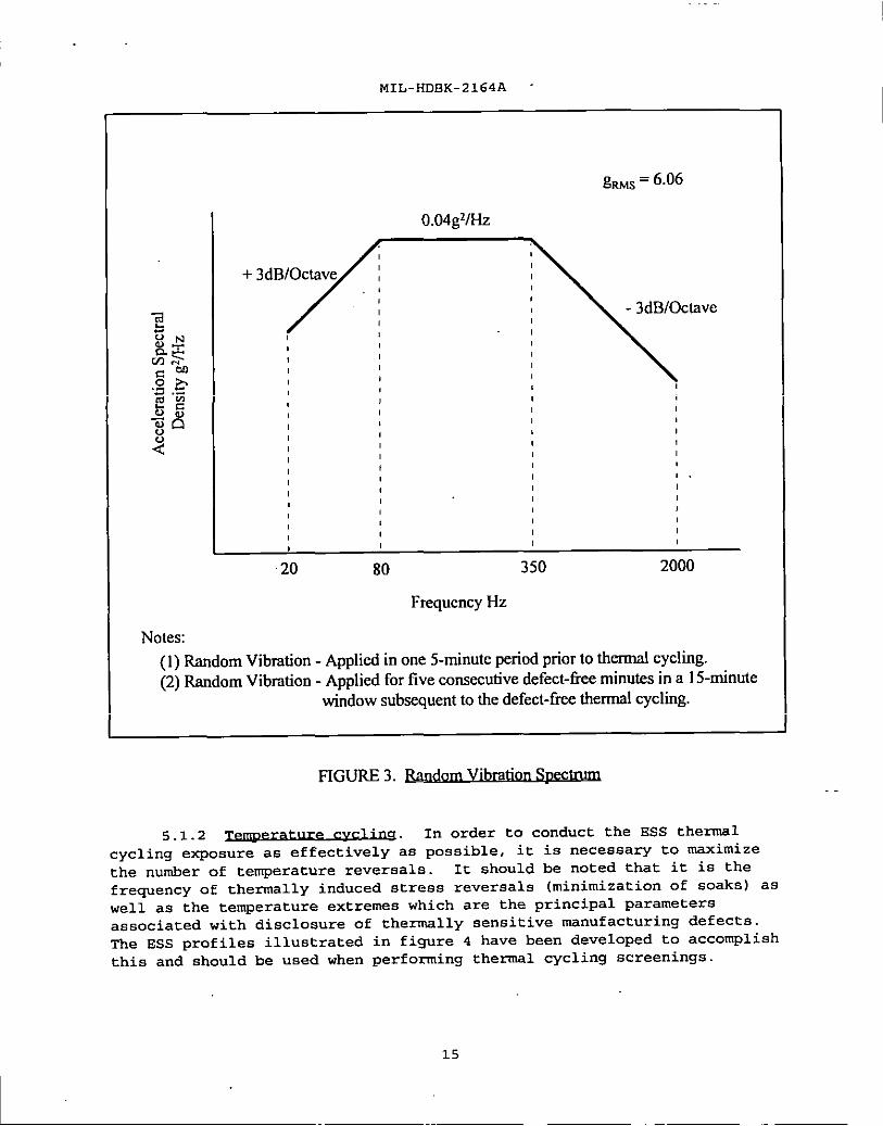
5.1.1 Figure 3 depictB a typiCal
random vibration spectrum that should be applied, as an input, to the
equipment to be screened with the equipment hard mounted to the screening
fixture and shaker system. In order to avoid any potential fatigue or peak
level damage due to resonances, it may.be necessary to notch the spectmm
at points of severe (Q z 10) resonant frequencies. These resonances should
be obtained from data accumulated during development screenings, or by
condu”cting a low level time sweep. This spectrum could severely overstress
good hardware. Vibration parameters should be tailored to the response
CharaCteKiStiCB of the item being screened.
5.1.1.1 Generally, random vibration
applied in a single axis effectively screens defects found in electronic
equipment. Crosstalk (vibration set up in the two axes not directly being
excited) dOeB in fact also provide some stimulation of defects sensitive or
unique to a particular axis. In certain cases it may be necesaaq to apply
vibration in more than one axis to provide adequate screening.
The selection of a single axis or multiple axes is dependent upon the
physical constmction and component layout as well as the susceptibility or
sensitivity to vibration of the hardware. The following guidelines should
be employed in defining which axis will be selected:
● If the electronic equipment contains printed circuit cards and
these cards are arranged predominant ly parallel to each other,
then the vibration input should be perpendicular to the plane of
the cards to assure maximum deflection and stimulation.
. .
. Vibration screenings are conducted during the development program.
The acquired data should be reviewed to determine the axis of
major resonances and transmissibilities (Q) values.
14
MIL-HDBK-2164A
gw~ = 6.06
I o.04gvH2
(
,
,( I
, ,
((
I(
I,
,
0(
If
,
, , 1.I
I, I
I (
,
I
,, , I
I,
20 80 350 2000
FrequencyHz
Notes:
(1)Random Vibration-Appliedinone 5-minuteperiodpriortothermalcycling.
(2)Random Vibration-Appliedforthe consecutivedefect-fleeminutesina 15-minute
window subsequenttothedefect-freethermalcycling.
FIGURE 3. Random V]brationSpcc~. .
5.1.2 In order to conduct the ESS thermal
cycling exposure as effectively as possible, it is necessary to maximize
the number of temperature reversals. It should be noted that it is the
frequency of thermally induced stress reversals (minimization of soaks) as
well as the temperature extremes which are the principal parameters
associated with disclosure of thermally sensitive manufacturing defects.
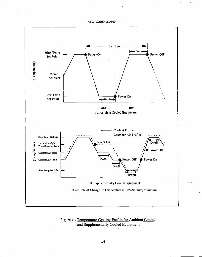
The ESS profiles illustrated in figure 4 have been developed to accomplish
this and should be used when performing thermal cycling screenings.
15
MIL-HDBK-2164A
* ‘“’’c’’”+HighTemp
*WI
SetPoint
@~
i?$
,
Room,
& Ambient
!,!,\,\
Low Temp,
SetPoint
,
l+Wll !
Time _
A. AmbientCooledEquipment
— CoolantPmtik
K@ TunPW Pd.,_ .-_. ---- Chamber AirProfile ~— . . .
,
G TtitickHi@ \
~ Tcmp@cra!in8limit
E: want H@ Ttmp —
& Golan!l.awTanP
b TmP SclPoiotW
B,SupplementallyCooledEquipment
Note ItnteofChangeofTemperatureis10“C/minute,minimum
Figure4- bture ~ Coolede
md SupgJementallyCooled ~ e
16
MIL-HDBK-2164A
A minimum of ten thermal cycles should be performed in order to eliminate
most latent workmanship defects in complex electronic equipment. The
applicable equipment specification will dictate chamber air temperature
extremes (high and low set points)
5. I.z.1 ~. The thermal survey establishes inputs for
the thermal cycling profile of the equipment, and varies slightly according
to the method by which the equipment is cooled.
5 .1.2.1.1 e for Steps a through k
should be followed for thermal surveys of ambient cooled equipment.
a. Attach thermocouples to components identified by thermal analysis
of the equipment as being representative of the various types and locations
within the equipment. Replace all equipment covers and properly seal, if
applicable.
b. Install the item to be screened in the temperature chamber at
room ambient temperature. Verify equipment operation and then turn the
equipment power off
c. After turning the equipment power back on, set the chamber
temperature to the equipment high temperature limit (high set point - see
paragraph 5.1.2) , and allow the chamber air temperature to increase to the
high ‘set point at an average rate of 10°C per minute, minimum. If the
chamber cannot provide the rate of temperature change required, auxiliary
heating mesns should be employed. The average rate should be computed for
the total chamber temperature excursion.
d. TUM off the equipment power when the chamber air reaches the
high temperature operating limit, and continue heating the chamber air
until the high temperature set point is reached. If the operating limit is
the same as the high set point, leave the equipment power on.
e. Maintain the chamber temperature at the high set point until 2/3
of the thermocouples reach within 10”C of the maximum operating
temperature. Record the time between the chamber reaching tbe high
operating temperature set point and 2/3 of the thermocouples reaching
within 100C of the msximum operating temperature (high temperature dwel 1
time) .
f. TUrn off the equipment power if left on in step d.
9. Set the chamber to the equipment low temperature limit (low set
point) (see 5.1. 2) and reduce the chamber temperature at an average rate of
10°C per minute. If the chamber is not capable of an average rate of 10°C
per minute, minimum, auxiliary cooling means should be employed. The
average rate should be computed for the total chamber temperature
excursion.
17

I
MIL-HDBK-2164A
h. Maintain the chamber air at the low set point until 2/3 of the
thermocouples reach within 10oC of the low set point. Record the low
temperature dwell time.
i. Repeat steps c through h, then repeat steps c, d and e. These
steps will result in three high temperature dwells and two low temperature
dwel 1s. The average of the last two high temperature dwells and the
average of the two low temperature dwells are the recommended dwell
periods
]. Turn off the equipment power if on, and lower the chamber air
temperature to room ambient Allow the equipment to stabilize at room
ambient temperature.
k. Set up the chamber automatic controls with the temperature-time
profile determined in steps c through j Repeat two cycles to verify
repeatability of the profile. Note that the time for one cycle should be
three hours and 20 minutes. In the event that the cycle duration exceeds
this, the increased time should be added to the low temperature dwell time.
5.1.2 .1.2 Steps a
through k should be followed for thermal surveys of supplementally cooled
eqipment (refer to Figure 4B)
a. Attach thermocouples to components identified by thermal analysis
of the equipment as being representative of the various types and locations
within the equipment. Replace all equipment covers and properly seal, if
applicable.
b. Install the equipment in the temperature chamber at room ambient
temperature. Verify proper operation of the article to be screened and the
supplementary cooling system. If the coolant specifications permit, the
equipment power should remain on for the next step.
c. Set the chamber temperature to the equipment high temperature
limit (high temperature set point) and increase the chamber ambient
temperature at am average rate of 10°C per minute, minimum. Simult aneoualy
raise the coolant temperature with the chamber ambient temperature until
the high temperature set point is reached. The equipment should be powered
until the high temperature operating limit is reached, and then the
screened article power should then be turned off
d. Continue to raiae the chamber ambient and coolant temperatures
until the high temperature set point is reached. Maintain this temperature
until 2/3 of the thermocouples are within 10”C of the equipment high
temperature limit. The time period between when the chamber reaches the
high temperature set point and when 2/3 of the thermocouples indicate
within loot of the equipment high temperature limit is the high temperature
dwell time.
18
1“
MIL-HDBK-2164A
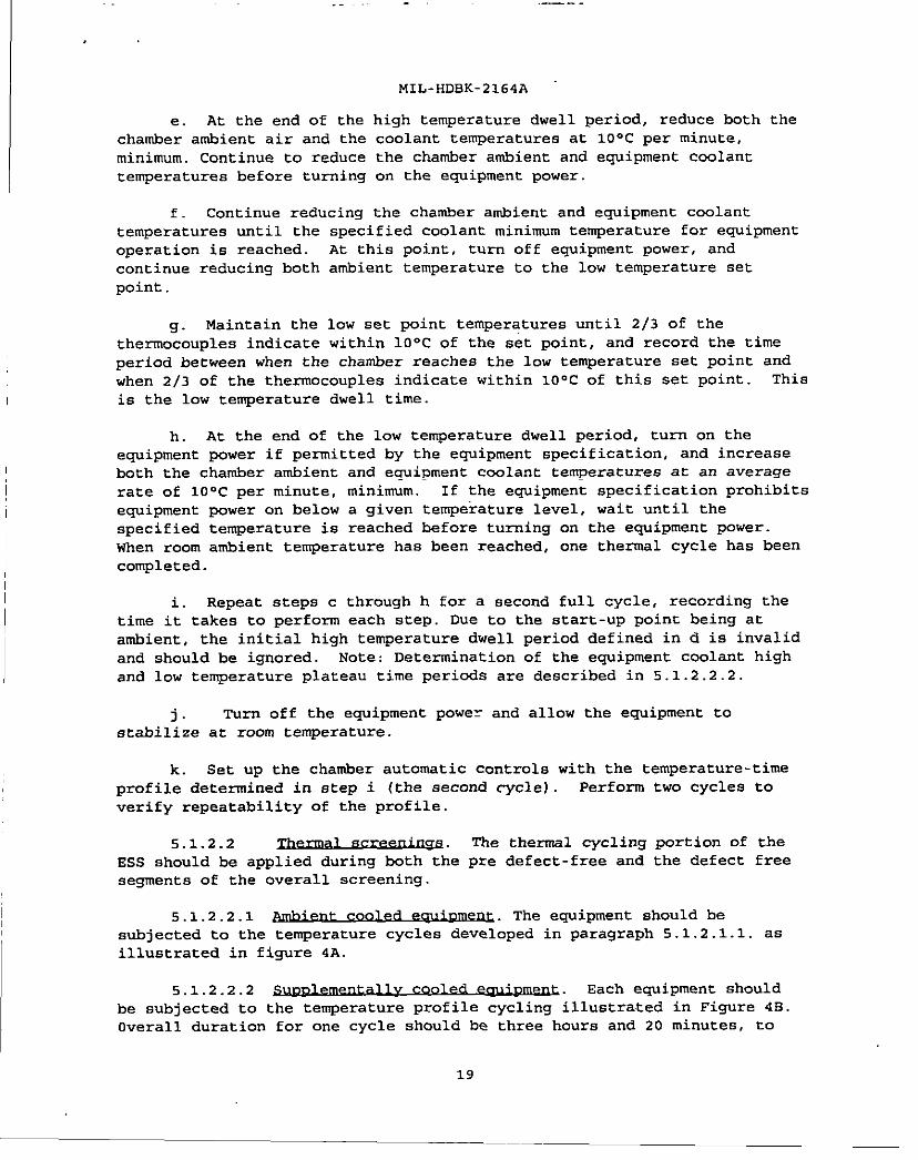
e. At the end of the high temperature dwell period, reduce both
chamber ambient air and the coolant temperatures at 10”C per minute,
minimum. Continue to reduce the chamber ambient and equipment coolant
temperatures before turning on the equipment power.
f. Cent inue reducinq the chamber ambient and equipment coolant
the
temperatures until the specified coolant minimum temperature for equipment
operation is reached. At this point, turn off equipment power, and
continue reducing both ambient temperature to the low temperature set
point.
9. Maintain the low set point temperatures until 2/3 of the
thermocouples indicate within 10”C of the set point, and record the time
period between when the chamber reaches tbe low temperature set point and
when 2/3 of the thermocouples indicate witbin 10°C of this set point. Thi8
is the low temperature dwell time.
h. At the end of the low temperature dwell period, turn on the
equipment power if permitted by the equipment specification, and increase
both tbe chamber ambient and equipment coolant temperatures at an average
rate of 10°C per minute, minimum. If the equipment specification prohibits
equipment power on below a given temperature level, wait until the
specified temperature is reached before turning on the equipment power.
when room ambient temperature has been reached, one thermsl cycle has been
completed.
i. Repeat steps c through h for a second full cycle, recording the
time it takes to perform each step. Due to the start-up point being at
ambient, the initial high temperature dwell period defined in d is invalid
and should be ignored. Note: Determination of the equipment coolant high
and low temperature plateau time periods are described in 5.1.2.2.2.
]. ‘rum off the equipment powe~ and allow the equipment to
stabi 1ize at room temperature.
k. Set up the chamber automatic controls with the temperature-time
profile determined in step i (the second rycle) . Perform two cycles to
verify repeatability of the profile.
5.1.2.2 The thermal cycling port ion of tbe
ESS should be applied during both tbe pre defect-free and the defect free
segments of the overall screening.
5.1.2 .2.1 ~. The equipment should be
subjected to tbe temperature cycles developed in paragraph 5.1.2.1.1. as
illustrated in figure 4A.
5.1.2 .2.2 v coo~ Each equipment should
be subjected to the temperature profile cycling illustrated in Figure 4B.
Overall duration for one cycle should be three hours and 20 minutes, to
19
—.. . . . .—.. - A., . . -.=
I
MIL-HDBK-2164A
provide at least 12 thermal cycles during each pre defect-free and defect-
free screenings using the results obtained from the thermal survey, (see
paragraph 5.1.2 .1.2) determine the duration of the high temperature
operating dwell. First, subtract the total of the up and down excursion
times and the high and low temperature dwell times from the overall cycle
time. During the remaining time, the equipment should be operated for 10
minutes maximum at the equipment coolant low temperature plateau and the
remainder of the time at the equipment coolant high temperature plateau.
5.2 ~. The total ESS program includes a physical
inspection, functional tests and periods of environmental exposure designed
to stimulate latent defects without incurring equipment fatigue damage.
Figure 2 presents the overall screening flow which should be used to verify
that an equipment is ready for operational use.
5.2.1 Documentation for the data acquisition should
include the following information:
● Screen identification
program name
item name screening section
tape recorder
tape speed
engineer/persOn administering screening
- date/time
excitation system
. Charnel information
accelerometer identification
accelerometer serial number
accelerometer sensitivity
charge amplifier gain
charge amplifier serial number
. Run informat ion
run identification
frequency range and level of excitation
IRIG (Inter-Range Instrument Group) time/tape footage,
beginning and end of run
IRIG time/tape footage, beginning and end of full level
vibration
5.2.2 ~. Each equipment under ESS should be
subjected to:
5.2.2.1 Each equipment should be
examined during appropriate stages of manufacture and assembly to
ensure proper workmanship has been applied.
20

. . .
I
MIL-HDBK-2164A
5.2.2.2 ~. An equipment operational test
should be performed, and data should be recorded. The test procedure
should include measurements required for a quantitative assessment of all
functional parameters including BIT functional performance parameters.
Verification of BIT operational capability should be included to the extent
possible by external equipment adjustment and without insertion of faults.
GO/NO GO evaluation should not be acceptable except for BIT. The record of
pretest data should be retained for use as a reference during subsequent
ESS
5.2.3 Eoy.ix Equipment submitted for screening
should be subjected to a fixed duration pre defect-free screening and
defect- free screening. The equipment operation should be continuously
monitored, and all functional parameters exercised repeatedly. at the
highest rate attainable. The mechanization of the functional check-out and
its speed of repeatability should represent a msjor task in the overall
formulation of the ESS prcgram. All vibration screening should be
conducted with the equipment hard mounted regardless of whether or not it
is to be installed on vibration isolators in its use environment.
5.2.3.1 ~ Each
eWiPment should be exposed to random vibration and” thermal cycling periods
as depicted in figure 2. Since the purpose of this screening is to
eliminate latent manufacturing defects, all defects detected during this
screening should be recorded and repaired, but should not count against the
acceptance of the equipment.
S.2.3 .1.1 ~. With the power on, the equipment should be
emOsed to One fiVe-MinUte burst of random vibration in the ~is deemed
most susceptible to vibratory excitation. Failures occurring during this
five-minute screening should be accrued (if possible) and corrected at the
conclusion of the five-minute period (See Appendix B) . The random
vibration spectrum should be:
20-80 Hz at 3 dB/Octave rise
80-350 Hz at 0.04g2/Hz
350-2,000 Hz at 3 dB/octave rolloff
5.2.3 .1.2 With the power on, the equipment should
be eubjected to a thermal cycling screening for a period of 40 hours in
accordance with the appropriate cycle depicted in figure 4. The required
number of thermal
The thermal
for cycling, are
specifications.
cycles may be interrupted for repair actions.
limits (high and low temperature extremes of chamber air)
those values of temperature defined by the equipment
21
---.-—--- -— .-. . . .—. — —. .. -—.-. —.. . .~. ..-. —— ------- . . . u ----- -.
I
MIL-HDBK-2164A “
Vibration and thermal cycling screenings are not to be applied
concurrently, but can be applied in the sequence defined in figure 2, that
is vibration, then thermal cycling, and again vibration.
5 .2.3.2 e (v,) After completion of the fixed
duration pre defect-free screening, each equipment should undergo a defect-
free screening under the same environmental conditions as in the pre
defect -free screening. The operating equipment (power on) should be
subjected to 40 consecutive defect-free hours under thermal cycling
conditions within an overall screening period of 80 hours maximum. Aft er
completion of the 40-hour defect-free thermal cycling requirement, the
eq~Pment should withstand five continuous minutes of random vibratiOn
without failure within a maximum screening time of 15 minutes An
e~ipment which does not successfully complete the defect -free period
within either allowable window should not be submitted for ESS compliance
and requires corrective action as described in 4 .7.2 and 4.7.3.
5.3 ~. Upon the successful
completion of the defect-free ESS phase, a final functional test should be
performed at room ambient conditions. This functional test should fully
verify the satisfactory operation of the equipment in accordance with the
parameters specified in the prime item specification. Operational
measurements should be compared with those obtained during the benchmark
testing referred to in 4.6, and evaluated based upon the specified
acceptable functional limits.
I 6. NOTES
(This section contains information of a general or explanatory nature that
I may be helpful, but is not mandatory.
6.1 ~. This document provides guidance for establishing,
documenting and implementing an ESS program.
6.2
Random vibration
Temperature cycling
Thermal cycling
Thermal survey
Vibration screening
Custodians:
Navy - SH
Air Force - 17
Preparing activity:
NAVY - SH
(Project RELI-0082)
Review activities:
Air Force - 84
DESC - AS
DLA - ES
22
I
I
MIL-RDBK-2164A
APPENDIX A
ESS DURATION, REDUCED SCREENING AND SAMPLING
A.1 sCOPE
A.l. l -. This appendix describes the approach, ground rules
and assumptions used to optimize the times for pre defect-free (PDF)and
subsequent defect-free (DF) screening under environmental conditions, and
define ground rules and techniques for reduced screening and sampling.
A.1.2 ~. The purpose of this appendix is to present the
background that led to the screening times stipulated in the main
body of the handbook, and define statistical plans for reduced
screening and sampling options.
A .2 APPLICABLE DOCUMENTS
A.2.1 G!2m?al. The documents listed below are not necessarily all
of the documents referenced herein, but are tbe ones needed in order to
fully understand the information provided by this handbook.
.A.2.2.1 and The following
standard and handbook ,form a part of this appendix to the extent apecif ied
herein. Unless otherwise specified, the issues of these documents are
those listed in the issue of the Department of Defense Index of
Specification and Standards (DODISS) snd supplement thereto.
STANDARD
DEPARTMENT OF DEFENSE
MIL-STD-1235 - Single snd Multi-Level Cent inuous
Sampling Procedures and Tsbles for
Inspect ion by Attributes With
Functional Curves of the
COnt inuous Sampling Plans
DEPARTMENT OF DEFENSE
MIL-HOBK-781 - Reliability Test Methods, Plans,
and Environments for Engineering
Development, Qualification, and
Product ion
(Unless otherwise indicated, copies of federal and military
specifications, standards, and handbeoks are available from the
23
~ ..- .- .—
MIL-HDBK-2164A
APPSNDIX A
Standardization Documents Order Desk, Bldg. 4D, 700 Robbins Avenue,
Philadelphia, PA 19111-5094. )
A.3 ASSDNPTIONS
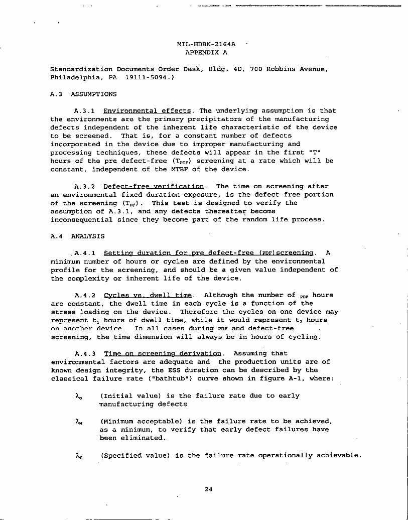
A.3.1 ~. The underlying assumption is that
the environments are the primary precipitators of the manufacturing
defects independent of the inherent life characteristic of the device
to be screened. That is, for a constant number of defects
incorporated in the device due to improper manufacturing and
processing techniques, these defects will appear in the first “T”
hours of the pre defect- free (T,,,)screening at a rate which will be
constant, independent of the MTBF of the device.
A.3.2 The time on screening after
an environmental fixed duration exposure, is the defect free portion
of the screening (TDF). This test is designed to verify the
assumption of A. 3.1, and any defects thereafter become
inconsequential since they become part of the random life process.
A.4 ANALYSIS
.A.4.1 (PDF)S~. A
minimum number of hours or cycles are defined by the environmental
profile for tbe screening, and should be a given value independent of
the complexity or inherent life of the device.
A.4.2 a Vs . Although the number of ~P hours
are constant, the dwell time in each cycle is a function of the
stress loading on the device. Therefore the cycles on one device may
represent tl hours of dwell time, while it would represent t~ hours
on another device. In all cases during PDF and defect-free .
screening, the time dimension wil 1 always be in hours of CYC1 ing.
A.4.3 Z.i.me.
on s~ . Assuming that
environmental factors are adequate and the production units are of
known design integrity, tbe ESS duration can be described by tbe
classical failure rate (“bathtub” ) curve shown in figure A-1, where:
L (Initial value) is the failure rate due to early
manufacturing defects
h (Minimum acceptable) is the failure rate to be achieved,
as a minimum, to verify that early defect failures have
been eliminated.
h (Specified value) is the failure rate operationally achievable.
24
MIL-HDBK-2164A
APPENDIX A
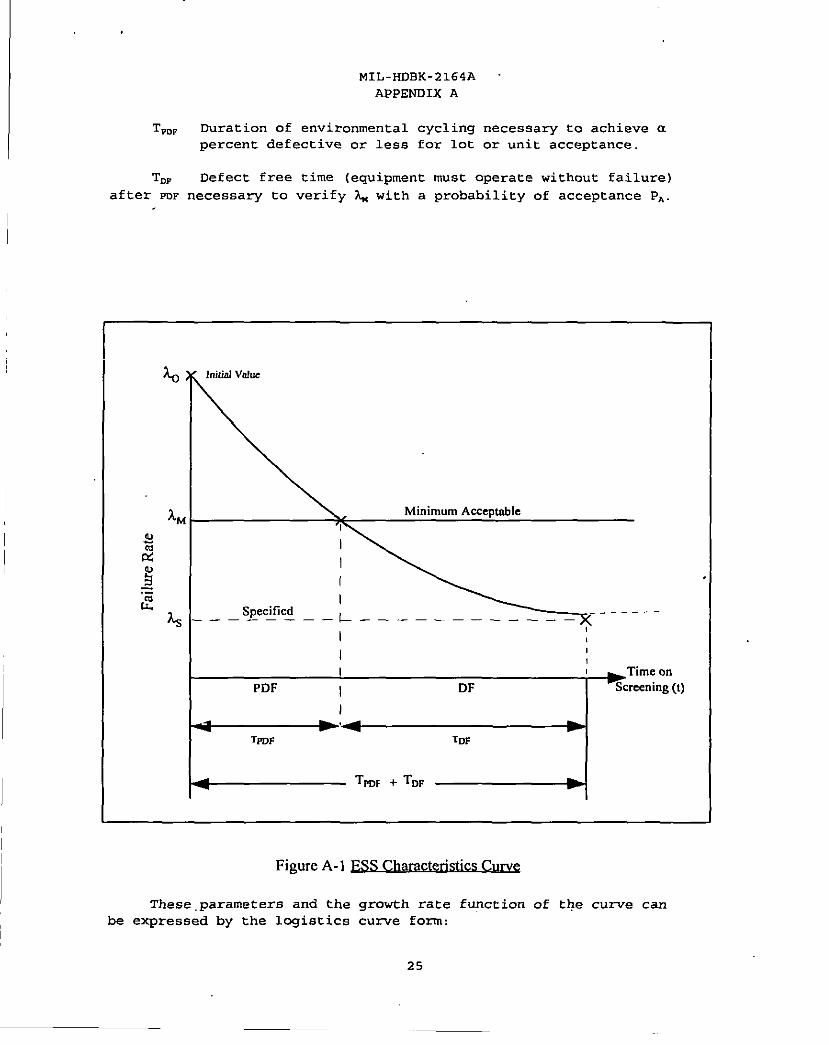
‘rPrw Duration of environmental cycling necessary to achieve a
percent defective or less for lot or unit acceptance.
TDP Defect free time (equipment must operate without failure)
after PDF necessary to verify ~ with a probability of acceptance PA.
AM Minimum Acceptable
~
2
I
3
I
Iq
I,
I T[meon
PDF I DF %creening(t)
I
4 -4 bTFWF TDF
4Tm~ + TD~ b
Figure A-1 E&S Chamteasha cu~e. .
These parameters and the qrowth rate function of the curve can
be expressed by the lcgietics &ne form:
25
.—. —,
MIL-HDBK-2164A
APPENDIX A
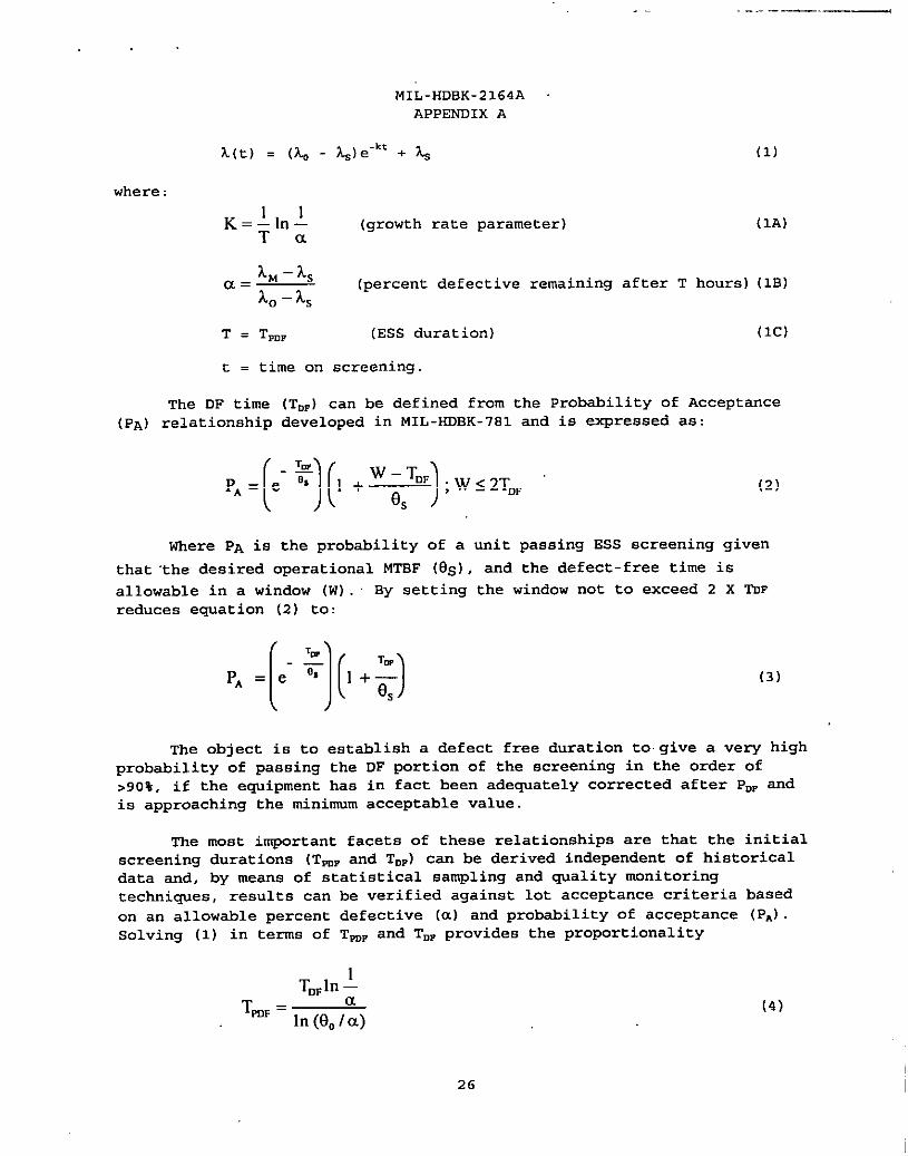
?&e”” + ~ (1)
(growth rate parameter) (1A)
(percent defective remaining after T hours) (lB)
(ESS duration) (lC)
t . time on screening.
The DF time (TDP) can be defined from the Probability of Acceptance
(PA) relationship developed in MIL-HDBK-781 and
PA=[5)(,+*);W.2TDF
ie expressed as:
(2)
Where PA ie the probability of a unit passing ESS ecreening given
that “the desired operational MTBF (es), and the defect-free time is
allowable in a window (W). By setting the window not to exceed 2 X TUF
reduces equation (2) to:
(3)
The object ie to establish a defect free duration to give a very high
probability of passing the DF portion of the screening in the order of
>90%, if the equipment has in fact been adequately corrected after P~~ and
is approaching the minimum acceptable value.
The most important facets of these relationships are that the initial
screening durations (TmF and TD=) can be derived independent of historical
data and, by means of statistical sampling and quality monitoring
techniques, results can be verified against lot acceptance criteria based
on an allowable percent defective (a) and probability of acceptance (PA)
Solving (1) in terms of TmF and TDP provides the proportionality
TDFln~aT,D, = —
In (f30/a)
26
(4)

,.
From the
expressed as a
10
MIL-HDBK-2164A
APPEWDIX A
expression (lB), the initial value eo = (l/&) , can be
function of the percent defective (a):
a
Expressing the minimum acceptable rate (~) in terms of a 2:1
discrimination ratio of specified (~) simplifies (5) to:
Equation (3) can now be transformed to:
(5)
(6)
(7)
This now provides a complete correlation between the time required in
PDF to precipitate manufacturing defects at some rate 90, and the
probability of accepting the device in DF.
A.4.4 ~.,,
A.4.4. I The criteria for screening duration is
that it be fixed for all devices independent of their life characteristics,
and that the TpDF = TE,F. To satisfy the assumptions of A. 3.1 and A.3 .2, eO
for all cases will be relatively small and constmt t -d is esti~ted frOm
evation (4) as 130= 1, when Tmp = TDP.
A.4.4.2 v of The probability
of acceptance for the DF portion of the screening is set at 290% to
ensure a low probability of rejection if, in fact, the defects have
been aderruatelv corrected after PDF. This also minim: zes the chance. .of random failure effects. The DF screening objective is not to
Iverify reliability.
A.4 .4.3 Within the constraint of
the PA, and solving equation (7) for values of a and TmP establishes
that a must be in the range of 1% and TmF . TW in the range of 50
hours or less to satisfy the criteria of A.4.4. 1 and A.4.4 .2, as
shown in table A-I.
1 A.4.5 From the environmental profile
guidelines; paragraph 5.2.1.1, the optimum number of houra of cycling
for all devices will be on the order of Tmr . 40 hours.
I27
..
. .
MIL-HDBK-2164A
APPEWDIX A
,“, ‘l&
Tmp = TDF (H0ur6)
-!L JCL 4.Q- -5!2
1% 96% 95% 91%
2% 88% 81% 74%
3% 78% 68% 57%
4% 66% 55% 43%
5% 58% 43% 31%
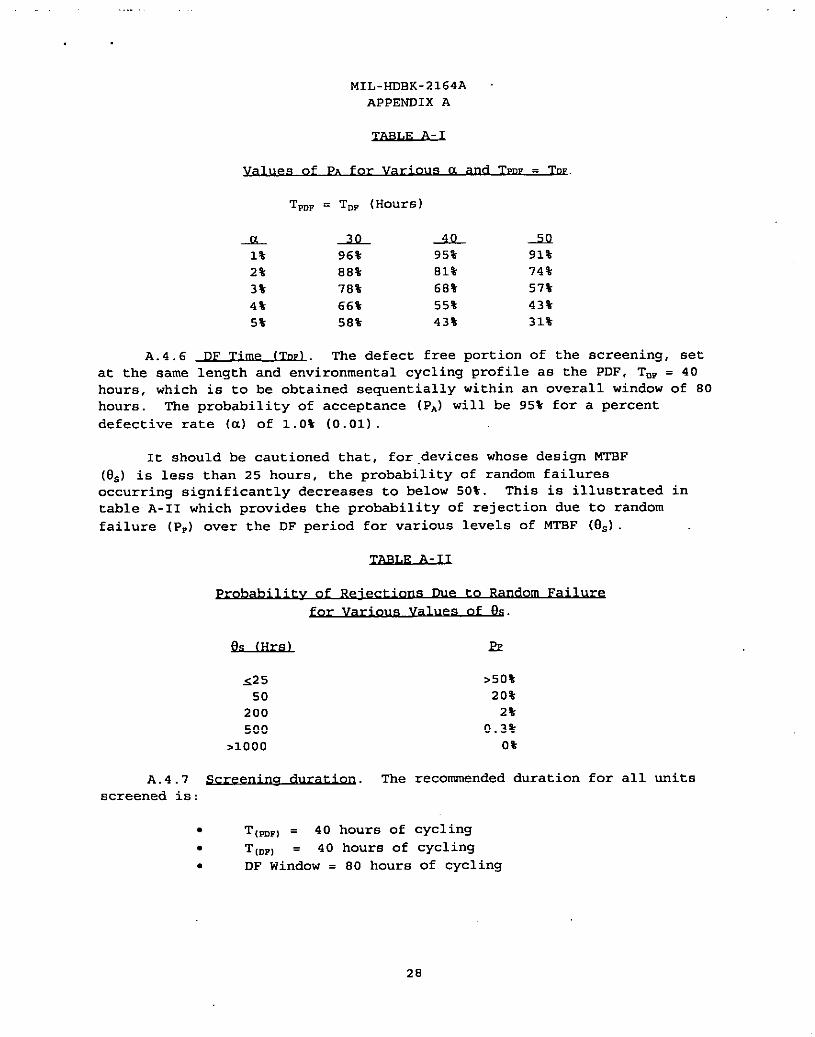
A.4.6 The defect free portion of the screening, set
at the same length and environmental cycling profile aa the PDF, TDP . 40
hours, which is to be obtained sequentially within an overall window of 80
hours. The probability of acceptance (PA) will be 95% for a percent
defective rate (a) of 1.0% (0.01)
It should be cautioned that, for devices whose design MTBF
(es) is less than 25 hours, the probability of random failures
occurring significantly decreases to below 50%. This is illustrated in
table A-II which provides the probability of rejection due to random
failure (P,) over the DF period for various levels of MTBF (9s)
of Due to
ea of es.
E?
<25 >50%
50 20%
200 2%
500 0.3%
>1000 0%
A.4.7 The recommended duration for all units
screened is:
. T,mp) = 40 hours of cycling
. T(DF) = 40 hours of cycling
. DF Window . 80 hours of cycling
28
MIL-HDBK-2164A
APPENDIX A
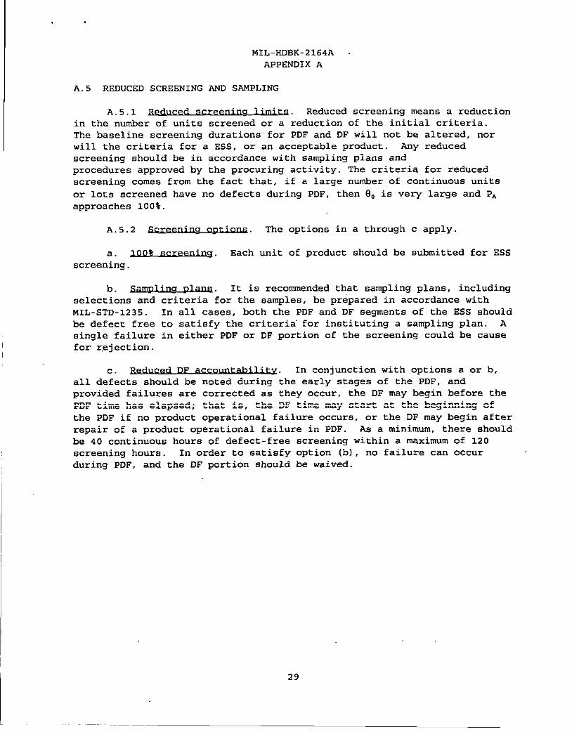
A. 5 REDUCED SCREENING ANE SANPLING
A. 5.1 Reduced screening means a reduction
in the number of units screened or a reduction of the initial criteria.
The baseline screening durations for PDF and DF will not be altered, nor
will the criteria for a ESS, or an acceptable product. tiy reduced
screening should be in accordance with sampling plans and
procedures approved by the procuring activity. The criteria for reduced
screening comes from the fact that, if a large number of continuous units
or lots screened have no defects during PDF, then 90 is very large and PA
approached 10O%.
A. 5.2 The options in a through c apply.
a. 100% sc~ Each unit of product should be submitted for ESS
screening.
b. It is recommended that sampling plans, including
selections and criteria for the samples, be prepared in accordance with
MIL-STD-1235 . In all caaes, both the PDF and DF segments of the ESS should
be defect free to satisfy the criteria” for instituting a sampling plan. A
single failure in either PDF or DF portion of the screening could be cause
for r.ejection.
c. DF In conjunction with options a or b,
all defects should be noted during the early stages of the PDF, and
provided failures are corrected as they occur, the DF msy begin before the
PDF time has elapsed; that is, tbe DF time msy start at the begiming of
the PDF if no product operational failure occurs, or the DF may begin after
repair of a product operational failure in PDF. As a minimum, there should
be 40 continuous hours of defect-free screening within a msximum of 120
screening hours. In order to satisfy option (b), no failure can occur
during PDF, and the DF portion should be waived.
I
29
..- ----- . ..— — . . . . . -—
. .
MIL-HDBK-2164
APPENOIX B
ESS TROUBLESHOOTING PLAN
B .1 SCOPE
B.l. l -. This appendix covers some considerations useful in
formulating a troubleshooting plan to address ESS failures.
B.1.2 B42Q.%e. The purpose of this appendix is to ensure that
adequate planning is accomplished prior to ESS to minimize the
environmental effects on the equipment to be screened during the pre
defect-free and defect free periods.
B .2 APPLICABLE OOCU14ENTS
This section is not applicable to this appendix
B .3 TROUBLESHOOTING CONS IDEATIONS
B.3. I C9nQ.nL. A detailed troubleshooting plan should be formulated
prior to the start of ESS. This plan may be a part of, or a supplement to,
the screening procedure. The plan should be coordinated with the
performance monitoring procedures, utilize Built -In-Test to the fullest
extent possible, and take full advantage of all data resulting from
performance monitoring, including trend data.
B.3.2 In preparing the plan the following should be
cons idered.
B.3 .2.1 Recognizing that failures may degrade the
ability to monitor the performance of the equipment, conventional fault
isolation and identification techniques may not be appropriate. It may be
advantageous or even necessary to perform functional screenings on a module
or a subassembly while exposing it to a specified environment. The
troubleshooting procedures should address this possibility, not only in
terms of powering, operating and monitoring the article, but also in terms
of applying the required environment (s).
B.3 .2.2 ~. Equipment performance should be monitored
during the application of specific environments. Nhen a failure occurs
which would mask other functions, the screening should be stopped and
troubleshooting procedures initiated to identify and cOrrect the defective
item.
B.3 .2.3 e Cvcl..lng. I“fthe failure is intermittent, the
environmental stimuli at the time of the failure should be noted and
troubleshooting procedures relating to the environment followed. Given
that the failure is associated with thermal cycling and the point in the
cycle at which the failure first appeared iB.known, troubleshooting should
be initiated while applying that thermal stress. If the specific failure
30

l-”
I
MIL-HDBK-2164
APPEW221X B
Doint is not known, or if the initial attempt is unsuccessful, complete
thermal cycles may be applied until the failure is reproduced and its
origin identified. It should be noted that, in practical terms, as many
additional thermal cycles as are necesaa~ can be applied without affecting
the equipment’s useful life.
B.3.2.4 ~. Unlike thermal cycling, the maximum time that a
unit can be exposed to the specified spectmm of random vibration, without
significantly affecting it useful life, is severely limited. With the unit
operational and its performance monitored, it should be exposed to the
specified spectrum of random vibration at the lowest gW level which will
cause the noted failure to reappear and allow identification of its origin.
In the event that the failure camot be duplicated at reduced levels, tbe
criticality of the failure should be examined and a judgment made as to the
advisability of continuing the effort, considering the risk of fatigue
damage associated with the application of reasonably high vibration levels
for extended periods of time.
To minimize the accumulation of equivalent random vibration screening
time, during diagnostic screening the vibration should be reduced to the
lowest feasible level. The total equivalent time for all acceptance and
diagnostic vibration screening should not exceed 20 minutes at tbe full
(O.04g2/Hz) level. Equivalent screening time is given by the following
expression:
(“”};AW)
23T
‘z
Where EQUIV is the equivalent g2/Hz level and T is the allowable time
in minutes.
FU4S Level PSD Level Equivalent Screening
(gllMs) (g’/Hz) Time (minutes)
6.0 0.04 20
5.2 0.03 4-I
4.24 0.02 160
3.0 0.01 1280
EXAMPLE:
Scmcniog (g’/Ez) Allowable EXPOSU~ 14stioof Allmvnble Equivalent SmtcningLevel Exposnrc Ttme
k DC,fecI-Free .04 5 minutes 5/20or0,23 5.0 mis”tcs
lkfti-FIu .04 4 ninutcs 4R0or0.20 4.0 times
Dhgmslk .02 20minwcs 2011600r0.125 2.5 minutes
Lwagnmtic .01 20minutes 2011280or.016 .3I minute
F7clkfccs-Fme .04 5 minutes 5/20or0.25 5.0 minutesTdd =0.84I 16,81MillUtM
31
. ..— —— . . .
.
MIL-HDBK-2164A -
APPENDIX C
NAVY PROGRAM MANAGEMENT GUIDANCE
c .1 SCOPE
C.1.1 S.COQ!?. This appendix covers some considerations useful in
I
planning and implement ing ESS for Navy programs.
C.1.2 OuzQsQ. The purpose of this appendix is to assist Navy
program managers in understanding the issues related to, and the
implementation of environmental stress screening. In order to affect
cent inuous process improvement, Navy program managers must tailor the
information in this appendix for the development of solicitation
requirements. Allowance should be made for the implemented processes to
change when warranted and justified by the facts.
C .2 APPLICABLE DOCDTIENTS
C.2..1 @n!?zal. The documents listed below are not necessarily all
of the documents referenced herein, but are the ones that are needed in
order to fully understand the information provided by this handbook.
C.2.2 9tlLPT GOV~.
The
following other Government documents form a part of this appendix to the
extent specified herein.
TRI-SERVICE TECHNICAL BRIEF 002-93-08 - Environmental Stress
Screening Guidelines
(Application for copies should be addressed to The Office of the
Assistant Secretary of the Navy (Research, Development, and Acquis ition)
Product Integrity, 2211 Jefferson Davis Highway, Arlington, VA 22244. )
TEOOO-AB-GTP-020A - Naval Sea Systems Command Environmental Stres6
Screening Requirements and APpl icat ion Manual for
Navy Electronic Equipment
(Application for copies should be addressed to the Standardization
Documents Order Desk, Bldg. 4D, 700 Robbina Avenue, Philadelphia, PA 19111-
5094. )
C.2.2 ~. The following document forms a
part of this document to the extent apecif ied herein. Unless otherwise
epeci fied, the issues of the documents which are DoD adopted are those
listed in the issue of the DoDISS cited in the solicitation. Unless
otherwise specified, the issues of documents not listed in the DoDISS are
the issues of the documents cited in the solicitation.
32
MIL-HDBK-2164A
APPENDIX C
INSTITUTE OF ENVIRONMENTAL SCIENCES (IES)
Environmental Stress Screening Guidelines for Assemblies
(Application for copiee should be addressed to the Institute of
Environmental Sciences, 940 East Northwest Highway, Mount Prospect, IL
60056. )
C .3 ESS APPLICABLE AREAS
Best design and manufacturing practice calls for the application of
environmental stress screening to:
. All material acquiaitiona that include electrical, electronic,
electro-optical, electromechanical or electrochemical components in prcgram
definition & risk reduction, engineering and manufacturing development and
production phases.
. Reprocurements where the cost of ESS implementation can be
amortized economical 1y
. Depot overhaul programs where opportunisties exist for substantial
cost savings
. Nondevelopmental items, such as commercial off-the-shelf (NDI-
COTS) and domestic or foreign military (tJOI-Military) items.
. Systems and equipment that have been specifically designated to
receive ESS.
ESS may be applied at any manufacturing level, from piece part6 to
end items. It is intended to screen defects in a manner that is not
harmful to properly manufactured material. Hardware proven to be too
fragile may be excluded because screening environments may be harmful. For
Navy prcgrams, all ESS requirements may be accomplished at the lowest
feasible level of assemmly in accordance (see Figure 1-1 of NAVS~ TEOOO -
AB-GTP-020A) . fil electrical/electronic parts may be purchased as screened
parts to the minimum quality levelB during Production, Fielding/Deployment,
and Operational Support (see Section 2.2.1 of NAvSEA TEOOO-AB-GTP-020A)
All other active parts may be upgrade screened as specified in Table 2-1
(for integrated circuits) and Table 2-2 (for discrete semiconductors) of
NAVSEA TEOOO-AS-GTP-020A. Al 1 parts meeting the minimum and upgrade
screened quality levels may be subjected to additional part requirements
(see Sections 2.2.1 and 2 .2.2 of NAVSEA TEooO-AB-GTP-020A)
C .4 BENEFITS OF ENVIRONMENTAL ST’RESS SCREENING
Proper application of environmental stress ecreeniig offers several
benefits : Reduced overall life cycle cost, on-time deliveries, improved
33
.- . . ..— —
,,,
MIL-HDBK-2164A
IAPPENDIX C
I performance after delive~, improved user confidence andlor satisfaction,
reduced support costs, and improved readiness.
While these benefits far outweigh the costs of implementation, they
do not come without a penalty. ESS must be implemented early in the
program and closely supervised throughout. The benefits are long term but
the requirements for people and funds occur early in the program.
ESS is normally conducted during the manufacturing process to detect
latent defects in parts and workmanship, but may also disclose design
deficiencies that were not detected during ~alification and engineering
tests. In addition, there are distinct benefits to conducting ESS during
development as well. A considerable percentage of the failures encountered
during a reliability growth (te6t, analyze and fix) test program may be
caused by poor workmanship and defective parts. These non-design related
failures can maak design-related failures, can cause schedule slippage, and
can adversely affect performance. By screening the item prior to this
testing, these adverse effects can be minimized. It is virtually
inmoasible to achieve desiqn reliability without reducing to a minimum the
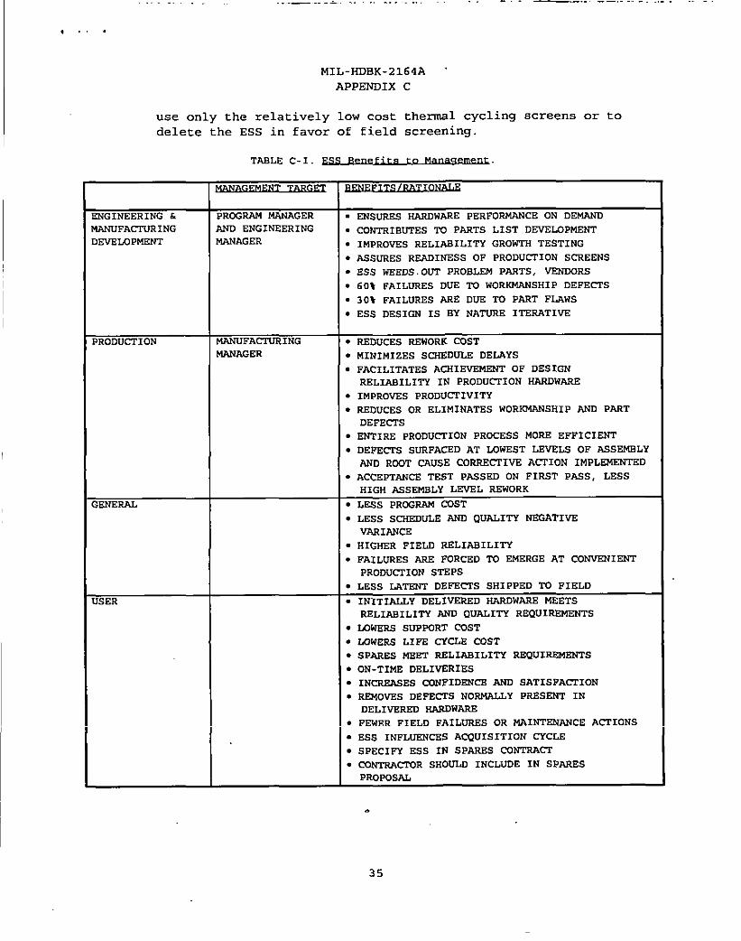
reliability degradation due to screenable flaws Additional benefits are
presented in table C-1.
C .5 PLANNING CONSIDERATIONS
It is important that ESS resources be in place when production
begins. The cost of rework in manufacturing escalates by orders of
magnitude as the assembly process proceeds from piece part level to printed
circuit board/module, unit, system, and to the user. Finding defects at
the lowest possible level of asaembly will tend to minimize rework costs by
reducing correct ive action time. However, some flaw types manifest
themselves only at the higher levels of assembly. Tailoring the screen to
the vibration and thermal characteristics of tbe hardware coupled with
defect population at each level of assembly is essential.
C .6 MANAGEMENT ISSUES
The fol lowing ESS management issues and guidance should be considered
to increase the probability of implementing a viable ESS program:
● How critical are the items proposed fOr Ess ad what level of
quality is required? Criticality would be high if a failure of
the item results in high probability of loss of life or an
inability to complete a mission, high life cycle cOst, Or high
cost of failure.
. The quantity to be procured should be considered. Where smsll
quantities are involved and the item does not qualify as a high
criticality item as given above, then it may be cost effective to
34
. . . .. .. . . . ------- . ..—. . . . . . . . . .
MIL-HOBK-2164A “
APPSTW31X C
use only the relatively low cost thermal cycling screens or to
delete the ESS in faver of field screening.
TAELE C-1.
~ ~
:NGINEERING h PROGRAM NANAGER s ENSURES ~WARE PERFORMANCE ON DEMAND
IANUFACIORING AND ENGINEERING ● CONTRIBUTES lW PARTS LIST DEVEUJPMXNTldW2LOPMENT N?+NAGER
● IMPRovES RELIABILITY GROWTH TESTING
● ASSURES RwINESS OF PRODOCTION SCREENS
● ESS WEEDS OUT PROBLEM PARTS, VENDORS
● 60t FAILURES DUE TO wORKMANSHIP DEFECTS
● 3O* FAILURES ?ftE OUE TQ PART FIAWS
● ESS DESIGN IS EY ~TURE ITERATIVE
BRODUCT 10N MANUFACTURING ● REDUCES REWORK COST
-AGER ● MINIMIZES SCHSDULE OELAYS
● FACILITATES ACHIEVENENT OF DESIGN
REL3AEILITY IN PRODUCTION SARDWARZ
● IMPROVES PRODUCIIVITY
● REOUCES OR ELIMINATES WORKMANSHIP AND PART
DEFECTS
● ENTIRE PRODUCI1ON PROCESS MORE EFFICIENT
● DEPECTS sORFACED AT LOWEST LEVBL2 OF ASSZMELY
m RDOT ~USE CORRECI’lVE ACTION IMPLEMENTED
● ACCEPTANCE TEST PA.SSED ON FIRST PASS, LESS
HIGH ASSENELY LZVEL REWORK
;ENERAL ● LESS PROGRAM COST
● L!3SS s~~ AND QUALITY NEGATIVE
VARIANCE
● HIGHER FIELD RELIAEILITY
● FAILURES ARE FORCED TO EMERGE AT CONVENIENT
PRODUCTION STEPS
● LESS L4TENT DE FIH21S SH1 PPED TO FIELD
JSER ● INITIALLY DELIVERED HMU)WARE MEETS
REL3AE1LITY AND QUALITY REQUIRSMENTS
● LOWERS sw PORT COST
● UiWl?.s LIFE CTCLR COST
. spmzs mm REL3AB1L1TT REQUIREMENTS
● ON-TIME DELIVSRIES
● INcREASES CCUJFIDZNCZ AND SAT1SFACI1ON
● REMOVES DEFECTS NORt4ALLY PRESENT IN
DELIVEREDzyxwvutsrqponmlkjihgfedcbaZYXWVUTSRQPONMLKJIHGFEDCBAlu+ltDW=
● FEWER FIELD FAILORES OR MAINTENANCE AC3’1ONS
● ESS lNFLUZNCZS ACQUISITION CYCLll
● SPECIFY ESS IN SPARES CUNTRACT
● CO_CIQR sHOULD INCLUDE IN SPARES
PRoPOS&
.
35
.
, ,!.
.
MIL-HDBK-2164A
APP~IX C
. Screen levels below those in the example presented in this
document are not recommended. The examples presented are starting
points only. They should be used to develop a screen based
on response surveys andlor tailoring approaches that will optimize
these screening profiles.
● Conduct of ESS at the piece part level should be evaluated to
ensure cost effective means is utilized to meet critical military
requirements.
. The ESS program plan should emphasize the following:
Commitment to and understanding of ESS
Failure report ing and corrective action system (FRACAS) A
FRACAS should be in place and operating.
Planned ESB profile optimization. technique. The Navy
recommends one of four random vibration techniques, and one
of two thermal cycling techniques. Each has both advantages
and disadvantages.
Managerial and technical approaches to ESS. The plan should
include proposed methods for determining initial screening
environment, applicable assembly levels, data collection,
failure analysis and corrective action, and procedures or
methods to be used in altering the prcgram.
Nondevelopmental items (NDI), such as commercial off-the-
shelf and domestic or foreign military items.
. The Navy program manager should also address the following
additional issues:
ESS profile requirements should not be specified in the RFP.
In general, it is better to allow contractors to propose an
6SS profile than to specify a particular profile, unless tbe
cent ract is a reprocurement and the original profile holding
fixtures, vibration machine and chamber capabil itiea are
contained on the drawings and are found to be satisfactory.
(Note: the original profile may have to be modified due to
changes in the production process and component
manufacturing variability. )
The ESS and quality history of the contractor.
The ESS results in rec&t contracts
36
.,
I
MIL-HDBK-2164A
APPENDIX C
When a contractor volunteers to participate in the
single process initiative and proposes an ESS process
change, the Navy program manager with the highest dollar
value contract should designate an individual as the
Department of the Navy ESS expert team member to support the
Navy team leader.
C .7 PROGRAM MANAGEMSN’I CHECKLIST
The following checklist should be used in the development of a
management plan for implementing ESS in each phase of the acquisition
process.
PRO+GF.AM DEFINITION .&RISK REDUCTION
. Establish adequate ESS funding. The basis of this verification
is the development of an historical data base on costs &
i~lement various screens versus return on investment (cost
avoidance )
● Assess the training needs of ESS personnel and develop a plan
to correct any identified training and/or qualification
deficiencies.
. Determine equipment availability, adequacy, capacity,
etc. to perform the intended screens.
. Identify special long lead equipment requirements (e.g. ,
fixtures, racks, etc. )
● Determine appropriate initial profile.
. Establish a PRACAS to report and analyze faults that are
precipitated out during screening.
ENGINEERING & MANUFACTURING DEVELDPH
. Cent inue to tailor, refine, and evaluate the adequacy of the
ESS profile, StriVing fOr an optimum screen. The absence of
fault precipitation during initial production or reprocurement
is an indication of a weak screen that needs further
optimization.
. Establish a FRACAS to report and analyze faults that are
precipitated out during screening.
. .APPIY ESS JUSt prior to the start of the TAAP program, “bile
continuing to strive for an optimum screen.
37
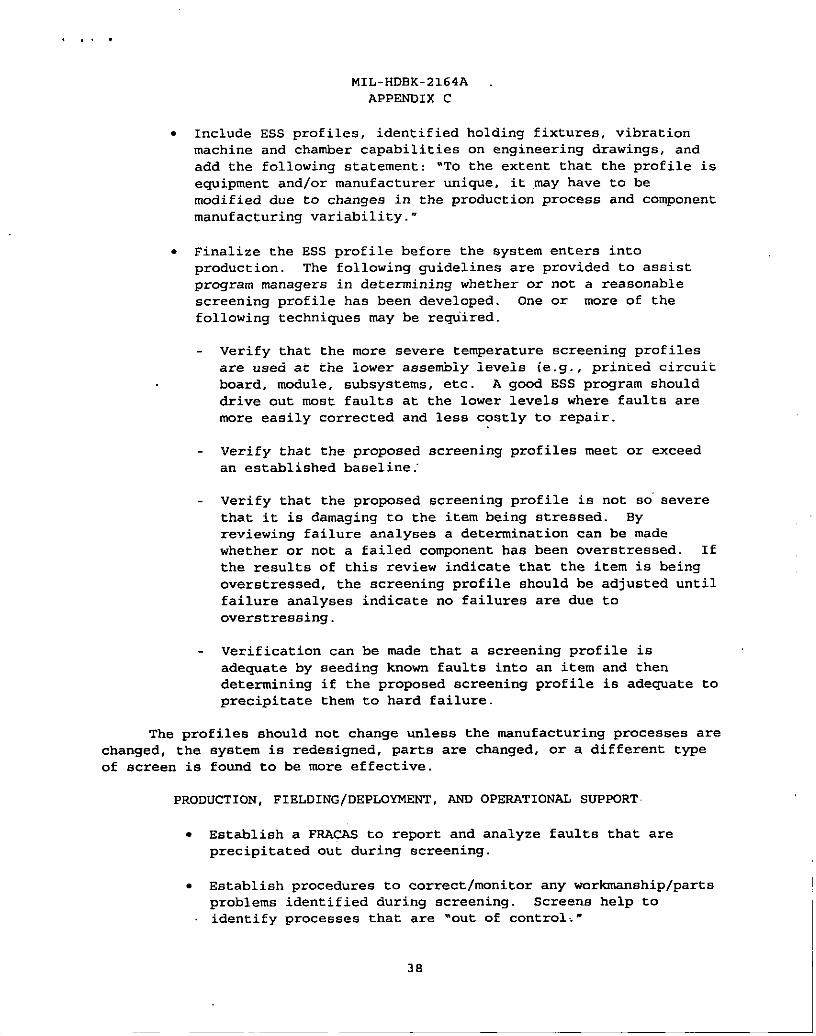
,!.
MIL-HDBK-2164A
APPENOIX C
. Include ESS profiles, identified holding fixtures, vibration
machine and chamber capabilities on engineering drawings, and
add the following statement: “To the extent that the profile is
e~ipment and/Or manufacturer ~iqe, it .~Y have tO be
modified due to changes in the production process and component
manufacturing variability. “
. Finalize the ESS profile before the system enters into
product ion. The following guidelines are provided to assist
program managers in determining whether or not a reasonable
screening profile has been developed. One or more of the
following techni~es may be re~”ired.
Verify that the more severe temperature screening profiles
are used at tbe lower assembly levels (e.g., printed circuit
board, module, subsystems, etc. A good ESS program should
drive out most faults at the lower levels where faults are
more easily corrected and less costly to repair.
Verify that the proposed screening profiles meet or exceed
an established baseline..
Verify that the proposed screening profile is not so”severe
that it is damaging to the item being stressed. By
reviewing failure analyses a determination can be made
whether or not a failed component has been overstressed. If
the results of this review indicate that the item is being
overstressed, the screening profile should be adjusted until
failure analyses indicate no failures are due to
overstressing.
Verification can be msde that a screening profile is
adequate by seeding known faults into an item and then
determining if the proposed screening profile is adequate to
precipitate them to hard failure.
The profiles should not change unless the manufacturing processes are
changed, the system is redesigned, parts are chsnged, or a different type
of screen is found to be more effective.
PRODUCTION , FIELDING/DEPLOYMENT, AND OPERATIONAL SUPPORT
. Establish a FRACAS to report and analyze faults that are
precipitated out during screening.
. Establish procedures to correct/monitor any workmanship/parts
problems identified during screening. Screens help to
identify processes that are “out of control. “
3s

MIL-HDBK-2164A
APPENDIX C
.,. .
● Provide parts failure information to parts manufacturers and
require continuous improvements to reduce these deficiencies.
. Establish procedures to track fielded systems and evaluate
field failure information against the effectiveness of the
current screens wherever possible.
. Establish criteria acceptable to the Government on when and
under what conditions 100% screening should be reduced to
sampling.
REPROCUREMENT AND DEPOT LEVEL OVSRHAUL
● Derive the same benefits of ESS in reprocurement items and
depot overhauled items as initial production environments.
Though the frequency failure may be lower for depot overhaul
items (infant mortality/design updates are already in place
through field use) , poor workmanship and bad replacement parts
are stil1 a problem in the depot overhaul environment.
Note: Numerous applications of ESS may” be harmful to equipment. Depending
on the particular equipment, the ESS program and the frequency of overhaul,
some marginal useful life of the equipment may be consumed.
● Require that all original 1y screened reprocurements be
screened. System level equipment should be screened at the
originally developed screen or equivalent screen. Where
original screens were not developed for replacement modules, a
determination based on criticality and cost should be made to
determine whether or not to develop an appropriate screen.
● Establish a FRACAS whenever there is a screening effort.
C .8 GUIDANCE SUNMARY
Top management’s commitment and attention is the key element in a
successful ESS program. Appendix D of mIES Environmental Stress Screening
Guidelines for Assemblies” contains a sample Environmental Stress Screening
Statement of Work (SOW) that will assist the Navy program msnager in
preparing contractual acquis ition documental ion.
Data Item Descriptions (DIDs) DI-RELI-130249 and DI-ENVR-81014 provide
additional guidance for the program manager in the preparation of ESS
documental ion. These two DIDs are often used for ESS acquisition
contracts. Contract Data Requirements Lists should be prepared in
accordance with local contracting office direction.
39
L
,,. .
STANDARD12ATION 00CUMENT IMPROVEMENT PROPOSAL
7hepreparingacdvilymustcompleteblocks 1.2, 3.and8.Inbl.xk 1. Lmti the comment.UmbaandrevisionIetfershould bw ghmn.
The submitter of this form must complete blocks 4,5,6. and 7.
The preparing acfirity must pmvido a repiy tifhin 30 days from receipt of tfds form.
NOTE This form may not be .SE4 to request cmples of documenfs, nor to request wafwers, or clarification of requirements on current contrads.
Commenfs submitted on fhis form do not cnnslifule or impiy authorization to waive any potion of the referenced document(s) or to amend cnnfracfua!requirements.
I RECOMMEND A CHANGE: 1.DOCUMENT NUMBER 2. DOCUMENT DATE (WMMDD)
MIL-HDBK-2164A 960619
00CUMENF nTLE
!NWRONMENTAL STRESS SCREENING PROCESS FOR ELECTRONIC EQUIPMENT
NATUSE OF CHANGE (identity pnragmph numtir md include propxcd re+rbr.. ifpassibk. Att@ exma sheets as needed.)
;, REASON FOR RJCOMMENDATlON
i, SUBMITTSR
4. NAME (LnsL FM f4ddla Initial) b. 0RGANW4TION
, AODRSSS (lKhldc Zi Code) d, TELSFHONS (Include M Cd.) 7. DATS SUB&UTfED (wMMDD)
(l) Cnmcrcial(2) DSN
(if qdicabk)
L PREPARING ACTIVITY
k NAME Tccluzkal Point ofContact(TPOC) b.TELEPHONE (Include Arm Code)(1) CQmmcxii: DW332-9121, EXI 228
@. DONALD CROSS, SEA 03K21
ADDRESS ALL CORRESPONDENCE AS FOLLOWS: TPDC 703-602-9121,EXT.228
:.ADDSE9S (hrdude Zip Cndc) IF YOU 00 NOT RSCEIVE A RSPLY W2TH2N 45 DAYS. CONTAC’P
COMMANDER, NAVAL SEA SYSTEMS COMMAND
#.’TTN:SEA 03R42Dcknx@diIyandSmntizzadonOfkc
2531JEFFERsON DAVIS HIGHWAY5203 kcsburg Pike, Suite 1403Falls Church, VA 22041-3465
ARLFNGTON, VA 22242-5160 Tdqimne 70?-756-2340 DSN 289-2240. . .
D FORM 1426.OCT 89 Frcvims.xMiomam.bmkw. ,xv.