Embed Size (px)
Citation preview

Applied R&M Manual for Defence Systems Part C – Supporting Theory
CHAPTER 45
ENVIRONMENTAL STRESS SCREENING
CONTENTS
Page
1 Introduction 2
2 Scope 2
3 The Stress Screening Programme 3
4 Background and Cost Effectiveness 7
5 Accelerated Testing Techniques 9
6 The Role of Management in Stress Screening 14
7 Stress Screening Test Plans 16
Version 1.0 Page 1
Chapter 45 Environmental Stress Screening
1. INTRODUCTION
1.1 Stress screening is a process in which imposed vibration, thermal and electrical stresses are applied for sufficient periods of time to precipitate those parts with either design defects and/or early life failure (ELF) characteristics. This stress screening procedure is normally referred to as Environmental Stress Screening (ESS), and is predominantly undertaken on electrical assemblies and software.
1.2 The ESS tests can show a manufacturer the problems that may exist in outstanding designs, and show them up before the item is produced. Testing at the design stage is carried out on all items at stresses exceeding those of the in-service operating envelope. Testing within the production stage is generally carried out at stresses within this envelope.
1.3 Design stage testing ensures a robust design and thus a high likelihood of in-service reliability and Production stage testing precipitates any ELF’s that may be present within the assembly. In this way any substandard assemblies can be removed before going into service. It should be noted that as confidence increases, production stage testing might not necessarily require testing of all 100% of produced items.
1.4 Within the last decade the usefulness of stress screening has become more apparent through the introduction of accelerated testing. Whereas traditional ESS used to replicate the field environment over many months, new screening machinery is able do this within the space of a few days. Naturally there are significant time and cost savings as a result. The main accelerated techniques are known as Highly Accelerated Life Testing (HALT) and Highly Accelerated Stress Screening (HASS).
1.5 ESS does not necessarily improve inherent reliability; it simply shows up design weaknesses in early testing and helps ensure that substandard assemblies are eliminated before field use. Reliability is determined by the design, and not necessarily by ESS testing. ESS ensures the products will be fit to operate in a given work environment. Neither is ESS a substitute for sole reliability testing; it has to be an integrated part of a sound reliability program, conducted through design, development, production and monitoring phases.
1.6 The practice of stress screening is now a widely accepted industry process for cost effectively improving product performance.
2. SCOPE
2.1 An explanation of modern stress screening processes is not complex but can be made simpler by splitting the product development cycle into predominantly two sections, namely Design and Production stages. Whilst the principle of application of ESS is very similar for the two, the way in which it is performed is quite different.
2.2 The traditional ESS tests used to take several weeks, if not months to perform, and were costly as a result. However, focus has now shifted towards highly accelerated means of testing that can replicate either in-service or extreme operating conditions in a matter of days (HALT and HASS). Naturally this is an easier and significantly cheaper option, allowing design flaws to be detected early and ELF’s precipitated quicker. Such accelerated techniques are also aimed at testing individual components, rather than the finished assembled item, as
Page 2 Version 1.0

Applied R&M Manual for Defence Systems Part C – Supporting Theory
previously conducted under older ESS processes. As a rule of thumb, HALT is performed in the Design stages and HASS in the production stages.
2.3 Hence this chapter addresses the design and production stages with reference to HALT and HASS as separate entities.
2.4 The layout to this chapter is as follows:
• The stress screening programme;
• Background and Cost Effectiveness;
• Design, HALT and the testing of software;
• Production and HASS;
• The role of management in stress screening, monitoring and feedback;
• Test Plans.
3. THE STRESS SCREENING PROGRAMME
3.1 Activities
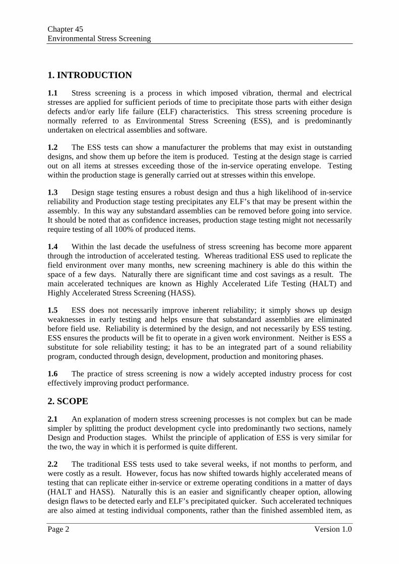
3.1.1 Plans for stress screening procedures are illustrated in Figures 1 and 2. As an overview, a stress screening programme should address the activities described below.
3.1.2 Stress screening will include thermal stress cycling as this is the most effective technique; thermal stressing contributes approximately two thirds more latent failures than vibration testing, which itself is ranked second. The dwell times must be sufficient for temperature stabilisation of the item under test, and importantly the stresses applied should be uniform in distribution. The vibration testing is also performed separately, normally at levels higher than would be for individual components. Having conducted the individual stress testing, the cycles will then be combined. The items under test should be checked for correct operation. For HALT the stresses will exceed those of the projected field environment, and with HASS the item is tested at stresses within the required envelope.
3.1.3 Stress screening tests should be fully developed during the design stage and especially before production, and should be optimised to produce cost effective benefits during production. Initially, the stress screening should be applied to 100% of all items and assembled components. This also includes those to be used as spares. However, as confidence in a particular design increases, the level of testing during design and production could be lowered; this is based upon a Statistical Test Plan. It is still important to remember that the majority of ELF’s are caused by poor workmanship, and so screening of 100% of items prior to delivery can be regarded as essential.
3.1.4 Stress screening should become integrated into the whole test philosophy and be seen as part of the design and production process, and not solely testing reliability. Screening does not necessarily make a product more reliable. The user of the test should be committed to understanding why tested units failed in the first place and indeed the physics of such failures. This is seen as one of the major stumbling blocks of widespread acceptance of stress screening.
Version 1.0 Page 3
Chapter 45 Environmental Stress Screening
Figure 1 - Introduction of Screening Procedures into a Development Programme
Page 4 Version 1.0
Applied R&M Manual for Defence Systems Part C – Supporting Theory
Sub-
Asse
mbl
y Te
st
Spec
ifica
tion
Equi
pmen
t Tes
t Spe
cific
atio
nSt
ress
Scr
eeni
ng T
est P
lan
Sub-
Asse
mbl
y St
ress
Scr
eeni
ng
Spec
ifica
tion
Equi
pmen
t Stre
ss S
cree
ning
Sp
ecifi
catio
nsU
nscr
eene
d C
ompo
nent
s
LEVE
L 2
Sub-
Asse
mbl
y St
ress
Sc
reen
ing
LEVE
L 3
Com
plet
e,
Uni
t,Eq
uipt
. St
ress
Sc
reen
ing
Post
Scr
eeni
ng
Test
and
Ful
l C
ertif
icat
ion
Insp
ectio
n
Post
-Sc
reen
ing
Test
Asse
mbl
y of
Uni
ts
and
Equi
pmen
t
Test
/ In
spec
tion
Proc
edur
es
Test
/ In
spec
tion
Proc
edur
es
Asse
mbl
y of
Pro
d.
Item
s
On-
Rec
eipt
In
spec
t.
LEVE
L 1
Com
pone
nt
Scre
enin
g
Pass
/ Fa
il R
esul
tD
ata
Bank
Pass
/ Fa
il R
esul
t
Dat
a An
alys
is
Tren
d R
epor
ts
Proj
ect
Man
agem
ent
Rec
tify
Scra
p
Engi
neer
ing
/ Qua
lity
Inve
stig
atio
n
Rea
dy
-No
Act
ion
-Rew
ork
Stoc
k
-Con
cess
ion
-Cor
rect
ive
Act
ions
–D
esig
n, P
roce
ss a
nd/o
r Pr
oced
ure
Cha
nges
Sub-
Asse
mbl
y Te
st
Spec
ifica
tion
Equi
pmen
t Tes
t Spe
cific
atio
nSt
ress
Scr
eeni
ng T
est P
lan
Sub-
Asse
mbl
y St
ress
Scr
eeni
ng
Spec
ifica
tion
Equi
pmen
t Stre
ss S
cree
ning
Sp
ecifi
catio
nsU
nscr
eene
d C
ompo
nent
s
LEVE
L 2
Sub-
Asse
mbl
y St
ress
Sc
reen
ing
LEVE
L 3
Com
plet
e,
Uni
t,Eq
uipt
. St
ress
Sc
reen
ing
Post
Scr
eeni
ng
Test
and
Ful
l C
ertif
icat
ion
Insp
ectio
n
Post
-Sc
reen
ing
Test
Asse
mbl
y of
Uni
ts
and
Equi
pmen
t
Test
/ In
spec
tion
Proc
edur
es
Test
/ In
spec
tion
Proc
edur
es
Asse
mbl
y of
Pro
d.
Item
s
On-
Rec
eipt
In
spec
t.
LEVE
L 1
Com
pone
nt
Scre
enin
g
Pass
/ Fa
il R
esul
tD
ata
Bank
Pass
/ Fa
il R
esul
t
Dat
a An
alys
is
Tren
d R
epor
ts
Proj
ect
Man
agem
ent
Rec
tify
Scra
p
Engi
neer
ing
/ Qua
lity
Inve
stig
atio
n
Rec
tify
Scra
p
Engi
neer
ing
/ Qua
lity
Inve
stig
atio
n
Rea
dy
-No
Act
ion
-Rew
ork
Stoc
k
-Con
cess
ion
-Cor
rect
ive
Act
ions
–D
esig
n, P
roce
ss a
nd/o
r Pr
oced
ure
Cha
nges
P
P
ass
F
F
ail
____
H
ardw
are
Mov
emen
t
- - -
-
Dat
a M
ovem
ent
……
...
Doc
umen
tatio
n M
ovem
ent P F
F P
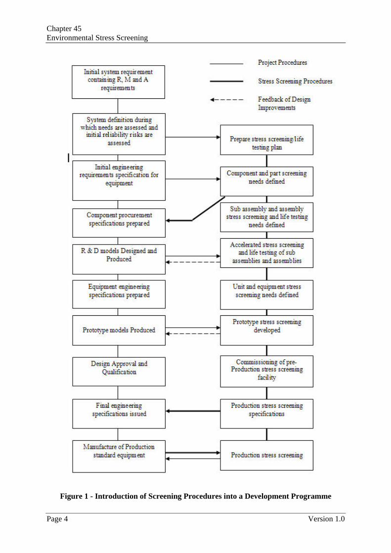
Figure 2 - Introducing a Stress Screening Procedure into the Production Process
Version 1.0 Page 5

Chapter 45 Environmental Stress Screening
3.1.5 Stress screening is a closed-loop process and relies upon information from monitoring to improve processes and screens; that is, it is an iterative process. Only through this can ESS be effective in terms of latent defect removal, and hence be cost effective. The screening process should evolve as manufacturing processes change; this in turn may eliminate latent defects but also introduce new ones.
3.1.6 Stress screening tests should be monitored to a depth which ensures that all failure modes cause an ‘item failure’ indication. In this connection continuous monitoring of items during the test should be undertaken where possible, since certain failures may only appear under stress and not at ambient conditions.
3.1.7 Stress screening tests involve monitoring and functioning and may incur potentially prohibitive costs in cases where specially designed signal generation and monitoring equipment is necessary. These cases will require some elementary means of providing confidence in the functional performance of the items, which will detect failures before and after ELF test, using normal factory test equipment.
3.1.8 In principle, stress screening can be applied at any level of assembly from component to complete equipment. Not all levels of any given project necessarily require individual screening test. Factors which would affect the decision include the quality of the bought-in components, the quality of manufacture and inspection, the risks associated with rework, the quality of that rework, the historical behaviour of similar items or products, etc. The decision as to where in the manufacturing process the screening procedures are best applied is one that requires a specific analysis of the cost effectiveness of screening at various levels. Guidance is given in the accompanying sections on the factors to be considered when making such decisions.
3.2 Documentation
3.2.1 Agreement between MoD and systems or service providers as to the adequacy of an ESS/HALT/HASS programme can be facilitated by a Stress Screening Plan. Such a plan should state to which items and where in the design and production process the screening procedures are to be applied, and the tests to be carried out on selected items from component level to complete equipment. The policy for repeat testing following a failure should also be defined. Repaired items should be re-screened and exceptions to this rule will depend upon several factors. Parts of this document could take the form of flow charts or similar network presentation, but additional textual material is required justifying the tests and procedures proposed in the document. To aid the preparation of this document, Figures 1 and 2 are provided to show where the screening procedures would typically occur in the development cycle.
3.2.2 As a code of practice, a Stress Screening Plan document requires, amongst other things, that specifications be prepared as an annex to the design and production test specifications detailing in quantified terms the test cycles to be applied, the items to which they are to be applied, failure criteria, the actions to be taken when failures occur, etc. These specifications should be entitled ‘Stress Screening Requirements’ and are necessary as the basis for costing the programme and for contractual compliance purposes. The environment to which the product will be subjected in the field must be considered early on, such as in the Design stage, and not as an after-thought. Such examples are safety, operating environment, mode of transport and geographic considerations.
Page 6 Version 1.0

Applied R&M Manual for Defence Systems Part C – Supporting Theory
3.2.3 A suitable Stress Screening Plan will contain:
a) A detailed understanding of the expected field environment the item will face.
b) A schedule of items to be tested.
c) A specification of the functional and environmental stress and the number of test cycles.
d) A specification of functional monitoring procedures and a definition of failure criteria.
e) A policy for repeat testing following a failure and subsequent repair and the procedure for feedback of corrective actions.
3.2.4 Records should be kept of all design defects and ELF failures revealed during stress screening and such records should be kept separately from those for other types of testing.
3.2.5 To enable the cost effectiveness of screening procedures to be monitored and optimised during the progress of a project it is recommended that contractors should, in addition to failures, also record:
a) The cost of rework involved in failure rectification.
b) The environmental conditions pertaining during a screening test.
c) Test durations, e.g. Elapsed Time Indicator readings at start and finish of each test cycle.
d) Number of switching cycles in each test cycle.
3.2.6 Such records will be necessary in any case for analysis of defects and/or ELF’s found by stress screening and in addition can be used to show that contractual requirements have been met.
4. BACKGROUND AND COST EFFECTIVENESS
4.1 General
4.1.1 This section discusses the argument for stress screening and indicates in general terms the cost benefits which accrue from integrating stress screening into the entire design and production phases of the development cycle.
4.2 Background
4.2.1 There is an awareness, supported by firm evidence, that early life failures exist in much equipment supplied to the Ministry of Defence. As a result defence capability is compromised, and ownership costs will be unnecessarily high due to the extra logistic support costs required to test and maintain newly delivered equipment. For example, the introduction of the ‘round of ammunition’ type of guided missile created problems by the fact that latent ELF’s remained in the missile with no possibility of detection by the armed forces. As a result, techniques began to be developed and evaluated for removing ELF’s before delivery. One such technique commonly used is ‘burn in’, where an item is screened at elevated
Version 1.0 Page 7

Chapter 45 Environmental Stress Screening
temperatures, under bias, to precipitate any failures before shipment. It was anticipated that, while this might be expected to increase production costs due to the increased testing involved, these costs would be offset by the reduced field maintenance costs, reduced warranty claims and the less quantifiable benefit to defence capability. In practice it has frequently been found that the application of well planned screening tests on selected components and assemblies can reduce production costs, if only in the reduction of rework by the manufacturer. For example, component screening will reduce rework and scrapping of the units into which the components are assembled, and so on up the manufacturing chain. It follows that modification of a design early in the project development cycle through stress screening will save substantially more money than if a fault is detected whilst in the field.
4.2.2 In recent years, attention has moved onto the accelerated forms of ESS. Traditional ESS tests used to take several weeks, if not months to perform, and were costly as a result. Accelerated means of testing can now replicate either in-service or extreme operating conditions in a matter of days. Naturally this is an easier and significantly cheaper option, allowing design flaws to be detected early and ELF’s precipitated quicker. Such accelerated techniques are also aimed at testing individual components, rather than the finished assembled item, as previously conducted under older ESS processes.
4.2.3 As already mentioned, stress screening is an important part of any product’s development. It has been demonstrated that product reliability has increased fourfold over that of unscreened electronics, and that field failures are now reduced to approximately one part in a million. The HALT and HASS methods have been seen to improve reliability by three orders of magnitude, with several companies achieving a 2500:1 reduction in test times using HALT. No field failures is quickly becoming an industry standard; hence it is considered that ESS methods will continually adapt and improve in order to meet these demands.
4.2.4 The length of screening is dependent upon the projected lifetime of the item within an operating environment. Of course, this totally depends on what the application of the item is; there are no set criteria, it totally depends upon what the user deems satisfactory.
4.3 Cost Effectiveness
4.3.1 The cost savings are undoubtedly one of the main arguments for stress testing, and are even greater when the testing is accelerated. Reducing the number of in-service and early life failures on a piece of equipment will:
• Reduce field expense costs;
• Reduce warranty claims cost;
• Reduce the amount of scrap and rework;
• Lower the unit costs;
• Increase product value and confidence;
• Improve the return on investment.
4.3.2 The earlier that a problem is located and resolved, the lower the cost in doing so. Screening costs are lowest at component level and progressively more costly at each higher level of assembly. For example, it can cost five times more to resolve a failure before
Page 8 Version 1.0

Applied R&M Manual for Defence Systems Part C – Supporting Theory
procurement than at the design phase, 11 times more before production, and approximately 400 times more before shipment. Hence, using stress screening to precipitate failures at the beginning of a project development cycle is far easier and cheaper to perform. It is no good refusing to stress test a design; send it into production and then realising there is a major problem at shipment stage. The costs will be excessive, needless to say the possible consequences.
4.3.3 Naturally there are initial cost penalties. The capital outlay on stress testing equipment will be high, as will the additional production costs, but assuming the test procedures are adequate then this cost will be comfortably exceeded by time and money saved in the long term. Any stress screening procedure will be cost effective when the costs saved through ELF recognition and early warnings of design issues outweigh those of the costs of the screening procedures.
4.3.4 When planning screening tests, the production cost of scrap and rework at various stages is the main parameter in determining where in the project development cycle, and to which items, stress screening should be applied. For example, given an electronic assembly where the components were to be potted, clearly screening should occur before potting so that, on failure, repair could be made. If screening occurred after potting the assembly would have to be scrapped on failure.
4.4 Other Benefits
4.4.1 Thermal stress screening produces an improvement in parametric stability and conversely, marginally stable parameters will often rapidly proceed towards failure after sufficient thermal stress.
4.4.2 The process has been found to be instrumental in promoting reliability growth, particularly when screening is applied during design. Growth will only result from the screening process, however, if defects are thoroughly investigated in engineering terms and the cause of systematic defects eliminated.
4.5 Cautions
4.5.1 It is important to appreciate that stress screening is controversial in certain ways and is an area constantly under review. Whilst the benefits are clear to see, it is argued that cycling a product with applied stresses prior to production/shipment will in fact reduce its strength and hence lifetime, even if the applied stresses are within the operating envelope. Both arguments are still under review and there is no evidence at present to argue that the point made here is valid.
5. ACCELERATED TESTING TECHNIQUES
5.1 General
5.1.1 Traditional methods for stress testing were to test items with electrical, thermal and vibration stresses over a period of several months, in order to predict in-service reliability. As already mentioned, this was a painstaking and costly process.
5.1.2 However, over the past few years UK companies have began to see the benefits of accelerated testing within the design and production stages. Accelerated testing is conducted
Version 1.0 Page 9
Chapter 45 Environmental Stress Screening
for mainly financial reasons. It enables field failures to be reduced to less than one part in a million, which in turn saves expenditure. Military applications, as a high quality, low production industry, have been one of the greatest benefactors of the new accelerated processes. Instead of concentrating too much on the Mean Time Between Failure (MTBF), emphasis is now shifting towards designing for reliability and specifying a durable life. MTBF itself is inherently negative, and support is growing for Maintenance Free Operating Periods (MFOP) and Failure Free Operating Periods (FFOP). Thus, to produce equipment with high reliability, military manufacturers should embrace new techniques that promote reliability, rather than just measure it. Accelerated testing and accelerated stress screening are two such methods; the most common are known as HALT and HASS, as introduced earlier.
5.1.3 For simplicity over the next few subsections, the product development cycle will be split into the two aforementioned areas, design and production. The principle of accelerated stress screening is very similar in both, yet the type of testing is not.
5.2 Design Stage – HALT
5.2.1 The HALT technique uses stress testing to reveal design weaknesses and fixing them before the equipment goes into manufacture. As a result, the design is more rugged and has a higher confidence of surpassing its in-service requirements. The key difference with HALT and traditional ESS methods is that stress factors, such as high temps, are applied directly to components or sub-assemblies and not the entire system. This can greatly speed up the process of precipitating failures.
5.2.2 Tested items were originally only tested in situations that replicated the field environment, which unsurprisingly was costly and timely. HALT uses a positive and negative stress exceeding the projected field environment in order to precipitate ELF’s and design defects. Hence, instead of testing the equipment to a satisfactory level, HALT can raise the confidence levels by defining actual maximum and minimum operating levels.
5.2.3 HALT thus marks a philosophy change from pass the test to find the problems and then fix them. Reliability is then driven into a product and not just a measure of it.
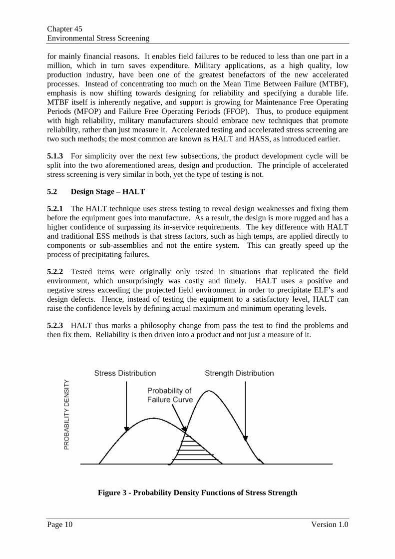
Figure 3 - Probability Density Functions of Stress Strength
Page 10 Version 1.0

Applied R&M Manual for Defence Systems Part C – Supporting Theory
5.2.4 Figure 3 above shows the stress/strength distribution overlap, where the marked region is the probability of failure. By removing failure modes the strength is increased, hence this line’s movement to the right, and hence reduction of the shaded area. However, as time passes, the variation of the strength distribution may increase, and so the shaded area may increase. By increasing the stresses applied during preliminary testing of equipment, HALT moves the stress/strength distributions back together and effectively reveals the time/usage dependent failure modes which would normally only be found after delivery.
5.2.5 As with previous stress screening, the minimum variables are thermal, vibration and electrical cycling. However this is not a finite list and further tests can be undertaken at the operator’s discretion. Such stresses applied are to some extent dependent upon the equipment’s operational environment. Each stress is applied in isolation in order to reveal specific defects for specific types of stresses. These are then combined in order to replicate a more severe environment. Unsurprisingly the combined stresses precipitate a greater number of failure modes.
5.2.6 Thermal stressing exposes ELF’s by imposing mechanical strain at points of stress in the item due to unequal thermal coefficients of expansion and also by exciting latent chemical degradation at high temperature. When a low level vibration stress is added to a thermal stress, the effect of differential thermal expansion is aggravated by vibration stress. When functioning under test is included, differential stressing is further aggravated by electrical stress leading to premature failure of weak items.
5.2.7 It is worth remembering that the larger the item to be tested, the more diverse its components are likely to be and hence larger the number of required thermocouples (for example). These couplings and wires are subject to exactly the same conditions the tested item is, and should be considered when examining HALT test results.
5.2.8 Throughout the HALT process the equipment should have power applied, where applicable, and importantly be monitored so that precise information can be obtained when failure occurs. Electronic equipment especially can have intermittent failures and constant monitoring is essential.
5.2.9 Stresses are applied until the point of failure has been reached; the stresses can then be reduced until operation again and hence the ‘operational limit’ can be ascertained. Stresses are then increased further to demonstrate how far beyond the operational limit the equipment can function whilst still being able to recover. Continuing until the unit does not recover will ascertain the destruct limit. This is where the difference between HALT and traditional ESS is apparent. HALT aims to remedy these causes of failures through design and/or process improvements, and continue this cycling until technological limits have been reached. This of course depends on the nature of the equipment tested, the cost and the time available.
5.2.10 HALT testing maximises the operating margin, provides a design margin beyond the specification, and thus reduces the probability of failure towards zero. A major advantage over traditional ESS methods is that HALT does not require large numbers of units to be tested. As mentioned earlier, the accelerated tests enable a greater level of confidence to be reached as designs are improved from a considerably earlier stage in the development cycle.
Version 1.0 Page 11

Chapter 45 Environmental Stress Screening
5.3 Design Stage – Software
5.3.1 The stress testing of software differs from the testing of hardware (i.e. electronic assemblies) in the fact that testing falls primarily in the design stage rather than production. Since software is a one-off and highly replicated package, its testing needs to performed earlier in the project cycle. For example, a piece of software within electronic hardware needs stress testing during design verification, as it is detrimental and costly to build the assembly and then discover that the software fails.
5.3.2 Hence software stress testing is analogous to HALT rather than traditional ESS strategies, as the stress testing can be applied early on so that there is adequate time to modify the software. In this way, once the software is deemed acceptable for the predicted in-service environment, then it is simply replicated.
5.3.3 Such stress testing of software includes worst case scenario inputs. For example, testing a processor for maximum number of inputs, with a failed server, will enable to designer to modify the design so that the software can be deemed to satisfy an operational limit.
5.3.4 There is little point in traditional stress screening tests prior to production as the software stress testing would determine a ‘successful’ design beforehand. Provided that the process used to replicate the software is identical each time, then there is little reason to suspect a problem prior to production. It also follows that there is no requirement to test the software in every item prior to production. The testing of software must not be confused with the testing of hardware.
5.3.5 It is still worthwhile testing the software (within the completed assembly) prior to shipment to ensure correct working order. This is not so much a form of burn in, rather a test to ensure a confident operation within the field environment. It is expected that any ELF’s found through HASS testing in such a piece of equipment will be as a result of the installed components and not the software.
5.4 Production Stage – HASS
5.4.1 Highly Accelerated Stress Screening (HASS) differs from HALT in that it is applied during the Production stage to precipitate and detect relevant defects. The same testing equipment is used as HALT but the testing is not as rigorous and is initially applied to 100% of items off the production line.
5.4.2 Unlike traditional ESS methods, HASS is not intended to simulate the field environment. The upper and lower limits obtained from the HALT tests are used in HASS to screen the product. The climatic and mechanical stresses used in HASS are also greater than those used in traditional ESS and so the test times are shorter and the tests more effective at eliminating ELF’s. The principle of HASS is to reveal, very quickly, any problems that may be present without altering the fatigue life of any installed components below the expected field life.
5.4.3 One part of HASS testing is known as burn in, which is when an item is screened at elevated temperatures before shipment, in order to prove the item is fit for service. Such testing is for 48 hours and occurs at temperatures (depending on the item) at 125˚C. It should, of course, not be confused with more general ESS.
Page 12 Version 1.0

Applied R&M Manual for Defence Systems Part C – Supporting Theory
5.4.4 Problems located by the HASS tests are corrected and the unit is again tested. Any significant changes may require a re-run of the HALT tests. Once HASS no longer reveals production and/or component failures, the number of tested items can be reduced in accordance with standard statistical test planning criteria, or Highly Accelerated Stress Auditing (HASA).
5.5 Summary
Accelerated testing techniques can be summarised as follows:
a) HALT goes far beyond traditional ESS techniques as it relies upon finding the problems quickly and early by testing to destruction. Thermal, electrical and vibration stresses are cycled in isolation and then in combination. This highlights the design weaknesses and ensures the product will be highly likely to satisfy the demands of the field environment. The unit under test is fully monitored and assessed at all times during the testing phase. HASS is then applied to precipitate any relevant defects which may have been introduced during the production phase, as well as eliminating any ELF’s before the item is shipped.
b) Correct application of HALT and HASS can have a huge influence on improving reliability and durability of Defence equipment. One of the most effective ways of advocating their use is to analyse their effective upon the ‘bathtub curve’ for product reliability. It focuses upon testing for all stages of the curve to push the failure rate to zero. This is illustrated in Figure 4.
Figure 4 - The Effect of HALT and HASS on the Bathtub Curve
c) Although HALT and HASS are methods for ensuring that product reliability is improved, they should not be mistaken for a new method of measuring MTBF, as seen earlier.
d) Cost savings are made since the number of units required for testing is significantly fewer than that for traditional ESS. This in turn vastly reduces the length of time
Version 1.0 Page 13
Chapter 45 Environmental Stress Screening
required for testing; traditional techniques used to take several months, whereas now accelerated testing can perform more functions in several days.
e) Ensuring a product’s reliability also reduces costs by virtually eliminating warranty claims. It is significantly cheaper to catch a problem early than to do so when the unit is shipped (i.e. through a product recall).
f) HALT and HASS are not methods for obtaining reliability assurance, but processes for driving reliability and durability into a design.
g) No field failures are vastly becoming common and so the military market needs to look for new ways to continually ensure high levels of reliability. HALT and HASS are two such new accelerated techniques that have certainly helped push reliability to new levels.
6. THE ROLE OF MANAGEMENT IN STRESS SCREENING
This section discusses the advantages, costs and considerations that management should be aware of in order to implement a successful stress screening programme. There is also a section detailing how stress screening should be integrated to the design and production processes.
6.1 Advantages
6.1.1 The primary advantages to management engendered by stress screening are:
• Improvement in product quality;
• Reduction of rework and scrap rates especially at higher levels of assembly;
• Reduction of warranty claim costs and product recalls;
• Improve market reputation;
• Quicker testing processes;
• Better understanding of product;
• Earlier failure detection;
• More satisfied customers.
6.1.2 An improvement in product quality reduces the total life cycle costs due to the reduced levels of field maintenance, improved product effectiveness and improved service capability. Much the same can be said about the other points as well; this is not an exhaustive list.
6.1.3 The use of stress screening, especially accelerated, can be a powerful tool for promoting reliability growth. The earlier a failure is detected then the cheaper it will be to fix, hence reducing the need for further maintenance costs of some sort or another.
6.2 Incurred Costs
The manufacturer may incur costs associated with the following requirements when implementing a stress screening programme:
Page 14 Version 1.0

Applied R&M Manual for Defence Systems Part C – Supporting Theory
a) Provision of additional environmental stress test facilities to meet production rates.
b) Provision of monitoring and test equipment, especially for new accelerated testing equipment.
c) Possible penalties from the time taken to screen during the production phase. However this cost is being lowered due to accelerated testing. Some of this cost may also be offset by the reductions in rework and scrap.
d) Additional manpower required to operate the test machinery and to be responsible for its monitoring.
e) Naturally the capital costs for purchasing and maintaining new equipment will be of primary concern when introducing stress screening into the design and production stages. However the benefits are considered to far outweigh the initial costs in performing stress screening as early on in the project lifecycle as possible.
f) The costs of screening should also be considered for proposals and tenders; again the benefits are viewed as outweighing such incurred costs.
6.3 Management Procedures
6.3.1 The role of management in any stress screening programme will be one of the key determinants in its success.
6.3.2 The main function of management is to ensure that screening is introduced as early as possible, ideally in the design phases with HALT testing. Any programme should be furnished with adequate support and resources, i.e. manpower, plant and time. It should also be integrated smoothly and with maximum cost effectiveness into the design and production processes. In order to be cost effective it is necessary to apply the screening at stages where it will be most successful in removing design defects and ELF’s, and in minimising the costs of rework and scrap. Figures 1 and 2 showed how and where screening could be incorporated into the project development cycle.
6.3.3 Management should also ensure that all the correct documentation, as previously described, is adhered to. Defect investigation procedures are required, and all design and manufacturing weaknesses should be monitored and reported at the appropriate review and progress meetings so that reliability growth may be achieved and sustained, and the whole screening plan optimised with regard to costs and effectiveness. In connection with the latter point it should be noted that the procedures should be subject to frequent review so that the screening plan may be subject to development changes. Even though HALT testing has reduced the need to test 100% of items at design stage, it can be recommended that the number of items tested under HASS be reduced also below 100%. This of course depends on the confidence levels, itself determined largely by management. After a burn in period all products will be periodically sampled to assure quality.
6.3.4 The managerial and engineering discipline imposed upon the stress screening test facility and its operations is of vital importance. The enforcement of adequate discipline requires that this test facility be under the direct control of a manager with quality assurance responsibility.
Version 1.0 Page 15

Chapter 45 Environmental Stress Screening
6.3.5 Management should ensure that all users of the testing programme have clearly defined roles in order to promote universal acceptance and understanding of the screening process.
6.3.6 An important and perhaps neglected point is that management should promote a paradigm shift within the organisation that stress screening is beneficial and should become a core competence. Screening personnel should realise that there is no such thing as a failure; realising there is a fault early on development cycle is no embarrassment as costs can be reduced as a result. This widespread acceptance of stress screening by all employees is a big concern for management.
6.3.7 In the event of a failure occurring during screening, the following actions should be considered in conjunction with the responsible design department:
a) Establish the direct cause of failure, the physics of failure and implement the necessary corrective action.
b) Determine the implications of failure on the assemblies that may have previously passed the screening test, and on those in line for future testing.
c) Determine whether any different form of screening process could have detected the failure earlier. If the testing was accelerated, consider whether a different combination of stresses and/or levels of stress may have precipitated any failures earlier. The stress screening test should not be used as a substitute for ineffective QA procedures.
d) On failure and rectification, the unit should be subjected to further screening, i.e. a HASS test. This continues until the product satisfies the demands. It may also be worthwhile to subject failed assemblies to a functional test. Failures, which are not confirmed at this test, should be resubmitted to the stress screening environment to confirm the failure and determine the necessary action.
e) Prepare a detailed report in respect of each failure stating the root cause and relevant corrective action. This information should then be held in some form of log or register for future reference, and shared throughout the design/test team to ensure further learning.
6.3.8 For HASS and/or burn in, a failed part or component should be removed to a local bonded store, be suitably identified and held pending investigation or disposal instructions.
7. STRESS SCREENING TEST PLANS
This section recommends the screening requirements to be applied at three levels of project development cycle, i.e. design and production; component level, sub-assembly level, and complete equipment level.
7.1 Test Guidelines
7.1.1 For electronic and electro-mechanical items two general-purpose test profiles are recommended as follows:
Page 16 Version 1.0

Applied R&M Manual for Defence Systems Part C – Supporting Theory
• A high stress profile to meet the requirements of equipment used in a highly exposed environment;
• A low stress profile to meet the requirements of equipment operated in a protected environment.
7.1.2 These test profiles are detailed in Table 2 and illustrated in Figure 5. It must be noted at this point that the test plans laid out are simply recommendations and are not exhaustive. Accelerated means of testing in recent years have evolved some test procedures, yet this section introduces the basic principles behind what the limits are to general stress testing, which are assumed to be based around identical principles to accelerated testing.
7.1.3 The number of test cycles to be included in any individual test plan is dependent upon the design of specific items. Generally speaking the failure rate of items can be expected to reach a sensibly constant level within 30 cycles of the specified test environment.
7.1.4 The selected number of test cycles in the plan should be considered as a minimum test. Items that fail during the test should be repaired and/or modified in terms of design, allowing a continuation of testing until the minimum number of consecutive test cycles is accumulated.
7.1.5 Pass/fail criteria should be determined proportional to the number of stress cycles and should specify the number of failure free cycles at the end of a test. In those cases in which failure occurs during this required failure free period the test should continue beyond the minimum requirement until the criterion for a pass is met.
7.1.6 Items not fulfilling the pass criterion should be subjected to a detailed investigation to establish the cause of failure. Items persistently failing suggest an immature design, poor workmanship or production short fall and in general persistent failures are a cause for concern.
7.1.7 Screening for design issues and ELF’s should be integrated into the manufacturing process following the conventional test/inspection procedures on assembly. A post screening test should also be carried out, to the production test specification. This test normally comprises an examination and functional test which ensures that contract conditions are satisfied, or at sub-assembly level, that incorporation into the next higher level of build is practicable. The purpose of screening will be largely negated if the post screening test involves much dismantling or disturbance of items, thus these influences should be minimised.
7.2 Progressive Screening Plan
As development and manufacturing experience increase and confidence is established in the design of a given item the test plan can be optimised. Depending on the results achieved, i.e. how quickly the failures are removed, the optimisation may involve increasing or decreasing the number of stress cycles. It is recommended, however, that initially during the development programme the number of stress cycles be conservatively large to provide good early data, so that generally there will be a progressive reduction in the numbers of stress cycles per test throughout project development. A progressive screening plan is shown in the following table, but progression to successive stages should be dependent upon a specified number of items, to be agreed with the Project Manager, successfully completing the previous stage by meeting the success/failure criteria within the minimum number of stress cycles.
Version 1.0 Page 17

Chapter 45 Environmental Stress Screening
Programme Stage Minimum Number of Stress Cycles
Success/Failure Criteria (number of consecutive stress cycles to be
failure-free at end of test)
R and D including Prototypes
30 10
Evaluation 20 7
Production 10 5
Table 1 – Example Progressive Screening Plan
7.3 Principal Applications of Stress Testing
The principal applications of stress testing which are recommended at all development stages are:
a) Component Screening: Screening of semi-conductors and micro-electronic devices which may be carried out by the vendor and includes pre-cap (prior to conformal coating) inspection, thermal cycling and of burn-in as specified in the appropriate procedures from BS 9450.
b) Sub-Assembly Stress Screening: Thermal stress screening to be applied to sub-assemblies at an appropriate stress level and for an appropriate number of stress cycles, together with vibration and a functional period with monitoring.
c) Complete Equipment Stress Screening: Vibration stress screening to be applied to assemblies or larger items as a final production screening test, together with appropriate Thermal Stress and equipment functioning and monitoring. The level and duration of vibration to be employed should be related to the structural response of the specific system. Random or Sinusoidal vibration may be used or other means of mechanical or acoustic excitation.
7.4 Component Screening (Semi-Conductor Devices)
7.4.1 These procedures apply to all semi-conductor integrated circuits, microelectronics and hybrid circuits. 7.4.2 Apart from the Pre-cap and Post-cap Visual Inspections and the Hermeticity Check these procedures may be applied either at the pre-cap or post-cap stage as appropriate. Zeners and diodes may be more conveniently tested at the post-cap stage whereas integrated circuit devices and hybrid circuits are more usually tested in the pre-cap stage.
7.4.3 Due to the time and expense involved in the burn-in screen, it is advisable to carry out a functional test prior to burn-in to reduce the cost of processing defective components which failed during previous screening activities.
Page 18 Version 1.0

Applied R&M Manual for Defence Systems Part C – Supporting Theory
Internal Visual Pre-cap Inspection
To BS 9450 Para 1.2.11
Stabilisation Bake
BS 9450 Para 1.2.7.4
> 36 hours duration.
Temperature Cycle
BS 9450 Para 1.2.7.14
Temps > 200˚C ± 5˚C, as specified > 10 cycles.
Acceleration or Shock Test
BS 9450 Para 1.2.7.10 and 1.2.7.7
Electrical Test
BS 9450 Para 1.2.5
Ensure operation at 25˚C
Burn-in
BS 9450 Para 1.2.10.3
168 hours at +125oC
Electrical Test (as above)
Hermeticity (Sealing) Check
BS 9450 Para 1.2.7.15.
External Visual
Post-cap Inspection
BS 9450 Para 1.2.3
Final Electrical Test
BS 9450 Para 1.2.5
100% testing, -55˚C to +125˚C
Figure 5 – Example Component Screening (Semi-Conductor Devices)
Version 1.0 Page 19

Chapter 45 Environmental Stress Screening
7.4.4 In cases of other critical component types not listed above, for which stress screening is considered desirable, specific procedures should be agreed between the component manufacturer and system designer. The procedures should include as a minimum the detailed stress testing process, the pass/fail criteria and the actions in the event of failures. Agreed procedures should be prepared as a clause to the procurement specification in a format acceptable to the master specification officer for the part category concerned.
7.5 Sub-Assembly Screening
7.5.1 These procedures apply to all printed circuit boards, electronic circuit boards, circuit modules, and other similar groups of circuit elements or electro-mechanical devices.
On receipt inspection of components/parts.
Assembly/Manufacturing process including test/inspection of sub-
assembly.
Repetitive Stress Screening with function monitoring in accordance
with stress levels and duration defined in Table 2 and Figure 8.
Post Screening Test.
Figure 6 – Example Sub-Assembly Screening
7.5.2 It is important to ensure that the sub-assembly is mounted in such a manner that unrepresentative modes of vibration are not included in the sub-assembly. Where this cannot be avoided and there is difficulty in adequately supporting the test item the vibration stress should be applied at a higher level of assembly. Remember also that any cables etc. used in screening are subjected to the same stresses as the tested item.
7.5.3 Post screening tests are part of the manufacturing process and comprise of examination and functional tests of sub-assemblies to ensure integration capability at the next higher level of assembly. The purpose of screening will be largely negated if the post screening test involves much dismantling and disturbance of sub-assemblies.
7.6 Complete Equipment Screening
7.6.1 These procedures apply to all assemblies, units or larger elements of equipment and are applied prior to the final certification inspection.
7.6.2 At unit and equipment level the application of thermal stress may not be possible in those cases where the thermal mass of the test item is large and the required rates of change temperature (>6o/min) cannot be achieved. In such cases it is important to apply vibration stressing with functional monitoring as the stress screening test.
Page 20 Version 1.0

Applied R&M Manual for Defence Systems Part C – Supporting Theory
On receipt inspection of components/parts.
Assembly/Manufacturing process including test/inspection of sub-assemblies, assemblies units and
equipment.
Repetitive Stress Screening with function monitoring in accordance
with stress levels and duration defined in Table 2 and Figure 8.
Post screening test and full
certification inspection.
Figure 7 – Example Complete Equipment Screening
7.6.3 Post screening tests are part of the manufacturing process and comprise of examination and functional test of items to ensure that contract requirements are satisfied. The purpose of ELF screening will be largely negated if the post screening test involves much dismantling and disturbance of items.
7.6.4 As a final production screening test of complete equipments at the full certification inspection stage, and ELF employing random vibration stress should be applied prior to delivery. The preferred method of stress screening for complete equipments is to apply bandwidth controlled random vibration in the range 20-2000Hz at a spectral density level chosen to achieve maximum excitation commensurate with minimum structural or functional degradation for a duration representative of an operational profile. Stress levels should be representative of the variations occurring in an operational profile.
7.6.5 Alternatives to random vibration may be permissible, e.g. Sinusoidal vibration at any non-resonant frequency, and requirements for specific projects should be agreed with the Project Manager.
Version 1.0 Page 21

Chapter 45 Environmental Stress Screening
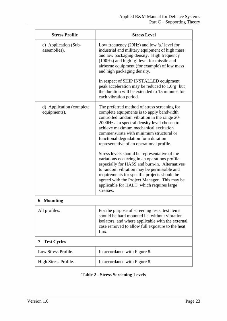
Stress Profile Stress Level
1 Upper Screening Temperature
Low stress profile. +50oC± 3oC.
High stress profile. 5oC below Design Qualification temperature, with a minimum of +65o± 3oC.
2 Lower Screening Temperature
Low stress profile. +20oC± 3oC.
High stress profile. -20oC± 3oC.
3 Temperature Ramp ( )tΔ
Low stress profile. Average of not less than 6oC per minute.
High stress profile. Average of not less than 6oC per minute.
4 Functional Operation
Profile Region ‘A’ Time required for test item to reach thermal equilibrium within the test chamber atmosphere.
Profile Region ‘B1’ Test item functional period with monitoring. Duration 1 hour minimum. Short lifted items to be subject to a functional test at the start and end of period ‘B1’ and ‘B2’ if applicable.
Profile Region ‘B2’ (High stress profile only).
Discretionary test period dependent upon equipment requirement to operate at low temperature, without a preliminary warm-up period.
5 Vibration
Low stress profile. Not obligatory.
High Stress profile.
a) Peak acceleration. %102.2 ±ng to %104.4 ±ng at any non-resonant frequency in the range 20Hz to 100Hz.
b) Duration. Dependent upon frequency, from 5 minutes to 20Hz, decreasing by 1 minute for each 20Hz, rise in frequency to 1 minute at 100Hz.
Page 22 Version 1.0
Applied R&M Manual for Defence Systems Part C – Supporting Theory
Version 1.0 Page 23
Stress Profile Stress Level
c) Application (Sub-assemblies).
Low frequency (20Hz) and low ‘g’ level for industrial and military equipment of high mass and low packaging density. High frequency (100Hz) and high ‘g’ level for missile and airborne equipment (for example) of low mass and high packaging density.
In respect of SHIP INSTALLED equipment peak acceleration may be reduced to 1.0’g’ but the duration will be extended to 15 minutes for each vibration period.
d) Application (complete equipments).
The preferred method of stress screening for complete equipments is to apply bandwidth controlled random vibration in the range 20-2000Hz at a spectral density level chosen to achieve maximum mechanical excitation commensurate with minimum structural or functional degradation for a duration representative of an operational profile.
Stress levels should be representative of the variations occurring in an operations profile, especially for HASS and burn-in. Alternatives to random vibration may be permissible and requirements for specific projects should be agreed with the Project Manager. This may be applicable for HALT, which requires large stresses.
6 Mounting
All profiles. For the purpose of screening tests, test items should be hard mounted i.e. without vibration isolators, and where applicable with the external case removed to allow full exposure to the heat flux.
7 Test Cycles
Low Stress Profile. In accordance with Figure 8.
High Stress Profile. In accordance with Figure 8.
Table 2 - Stress Screening Levels
Chapter 45 Environmental Stress Screening
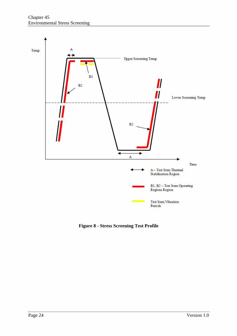
Figure 8 - Stress Screening Test Profile
Page 24 Version 1.0
Applied R&M Manual for Defence Systems Part C – Supporting Theory
LEAFLET C45/0
REFERENCE
1 MIL-HDBK-781A, Handbook for Reliability Test Methods, Plans,
and Environments for Engineering, Development Qualification, and Production. US DoD.
2 British Standard BS 9450 (1998), Specification for Integrated Electronic Circuits and Micro-Assemblies of Assessed Quality (capability approval procedures). BSI.
3 Journal of the RAC, Third Quarter – 2003, A Beginners Guide to HALT, US DoD Reliability Analysis Centre.
4 START, 7(3), 2003, Environmental Stress Screening, US DoD Reliability Analysis Centre.
Version 1.0 Page 1
Chapter 45, Leaflet 0 Environmental Stress Screening
Page 2 Version 1.0