Embed Size (px)
Citation preview

The world’s leading sustainability consultancy
General Electric Aviation
Environmental Monitoring Plan General Electric Plant #2
270 Windcrest Road North Clarendon, Vermont 05759
July 2013
Revised October 2013
www.erm.com

General Electric Aviation
Environmental Monitoring Plan
General Electric Plant #2 270 Windcrest Road North Clarendon, Vermont 05759
July 2013
Revised October 2013
__________________________________
R. Joseph Fiacco, Jr., P.G. Principal –in-Charge
______________________________________
Catherine E. Regan, P.E. Project Manager
Environmental Resources Management One Beacon Street, 5th Floor Boston, MA 02108 T: 617-646-7800 F: 617-267-6447

iii
TABLE OF CONTENTS
1.0 INTRODUCTION 1-1
2.0 GROUNDWATER MONITORING 2-1
2.1 SAMPLE LOCATIONS AND ANALYTICAL PARAMETERS 2-1
2.2 SAMPLE COLLECTION PROCEDURES 2-2
2.3 QUALITY ASSURANCE AND QUALITY CONTROL 2-3
2.3.1 DOCUMENTATION PROCEDURES 2-3
2.3.2 EQUIPMENT MAINTENANCE AND CALIBRATION 2-3
2.3.3 CLEANING AND DECONTAMINATION OF EQUIPMENT 2-3
2.3.4 QUALITY ASSURANCE / QUALITY CONTROL SAMPLES 2-3
3.0 REPORTING 3-1
4.0 POTENTIAL MODIFICATIONS 4-1
LIST OF FIGURES
Figure 1 Site Location Map
Figure 2 Site Layout
LIST OF APPENDICES
APPENDIX A STANDARD OPERATING PROCEDURES

ERM 1-1 GE - OCTOBER 2013
1.0 INTRODUCTION
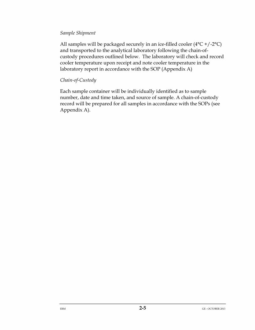
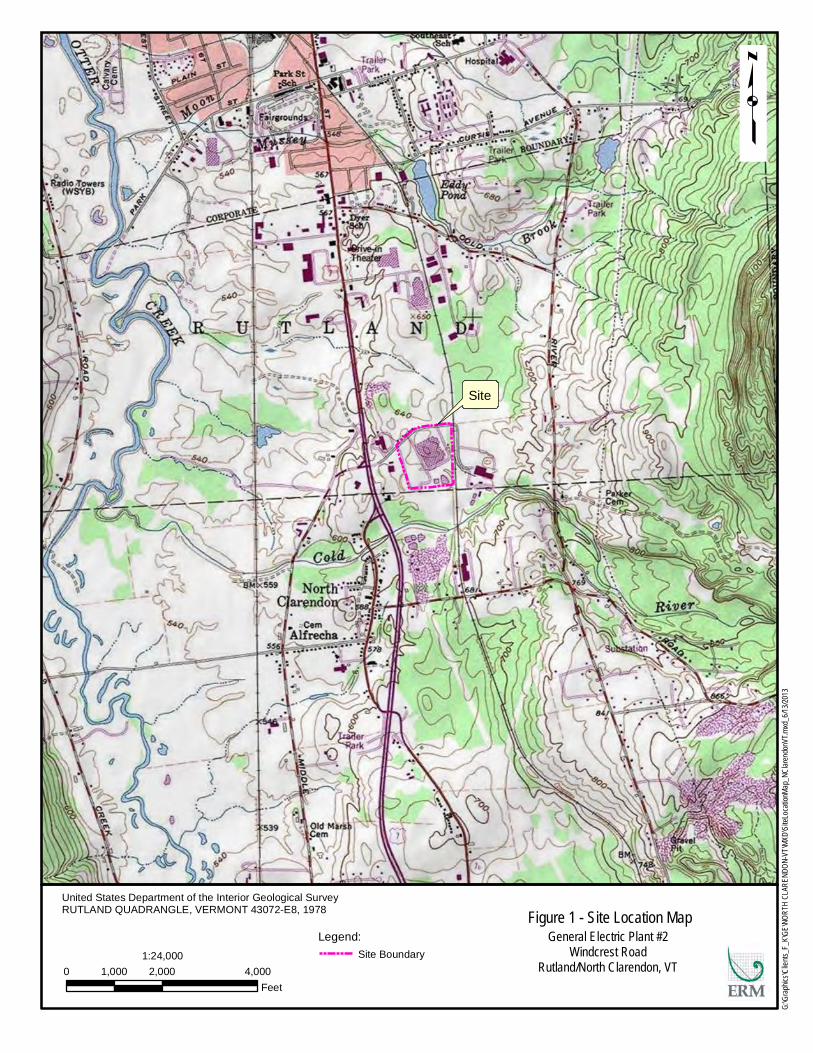
This Environmental Monitoring Plan (EMP) presents the details of the post-closure and corrective action monitoring program for the General Electric Company (GE) facility at Windcrest Road in North Clarendon, Vermont (Site). A Site Location Map is presented as Figure 1 and a Site Layout is presented as Figure 2.
The GE facility manufactures gas turbine engine components, including vanes and blades, and associated tooling from various metal alloys. GE operated a regulated landfill unit (Landfill) at this Site for metal hydroxide sludge generated by this facility from 1976 to 1986. The Landfill received wastes defined as hazardous (i.e., F006 waste) by the Vermont Hazardous Waste Management Regulations (Regulations) under §7-210. The Site is subject to Resource Conservation and Recovery Act (RCRA) corrective action provisions due to the presence of the closed-in-place Landfill, solid waste management units (SWMUs) and areas of concern (AOCs).
This EMP has been prepared to satisfy the requirements of 40 CFR section 264.117 (a)(1)(i) and will serve as guidance for personnel performing groundwater monitoring during the post-closure period. Section 264.117 a (1) (i) states that post-closure care must consist of monitoring and reporting in accordance with relevant subparts F, K, L, M, and N of 40 CFR part 264. These subparts define requirements for Groundwater Protection at Solid Waste Management Units, Surface Impoundments, Waste Piles, Land Treatment, and Landfills, respectively. GE will follow subparts F and N, which are the two subparts applicable to this Site. A groundwater monitoring system is in place and will be utilized to monitor the condition of the groundwater at the point of compliance (POC) in accordance with this EMP.
This EMP describes the monitoring frequencies for each monitoring point, analytical parameters, sampling procedures, recordkeeping and documentation.

ERM 2-1 GE - OCTOBER 2013
2.0 GROUNDWATER MONITORING
The following subsections describe the field activities required to implement the groundwater monitoring program at the Site.
2.1 SAMPLE LOCATIONS AND ANALYTICAL PARAMETERS
GE will continue to monitor groundwater quality in the wells listed in Table 1 and shown in Figure 2. The sampling frequency and analytical parameters to be analyzed are specified in Table 1. Groundwater analytical results will be compared to the Vermont Department of Environmental Conservation (VT DEC) Groundwater Quality Standards (VTGWQS) listed in Table 2.
Table 1 Groundwater Monitoring Schedule
Well ID Sampling Frequency
Analytical Parameters Reported Analytical Method
B-11 Biennially 1,1,-Dichloroethene EPA Method 8260
B-14 Biennially 1,1,-Dichloroethene EPA Method 8260
B-16 Quarterly 1,1,-Dichloroethene EPA Method 8260
Biennially Nickel EPA Method 200.7
B-17S* Quarterly 1,1,-Dichloroethene EPA Method 8260
Biennially Nickel EPA Method 200.7
B-27 Quarterly 1,1,-Dichloroethene EPA Method 8260
B-28 Biennially 1,1,-Dichloroethene EPA Method 8260
Table 2 Vermont Groundwater Quality Standards
Reported Parameter VTGWQS (ug/l)
1,1,-Dichloroethene 7
Nickel 100

ERM 2-2 GE - OCTOBER 2013
2.2 SAMPLE COLLECTION PROCEDURES
Groundwater monitoring will be performed in accordance with the Standard Operating Procedures (SOPs) included in Appendix A.
Prior to sampling, each monitoring well will be gauged relative to the top of casing with an electronic resistivity probe, which measures the groundwater level. Measurements of groundwater elevations will be made to a precision of +/- 0.01 feet. The measuring device will be decontaminated prior to use in each well.
Groundwater samples will typically be collected using passive diffusion bags (PDBs). A PDB is a polyethylene bag filled with distilled water that relies on diffusion of the analytes across the permeable membrane of the bag to achieve a state of equilibrium between water in the PDB and groundwater in the well. Equilibrium occurs within two weeks of PDB deployment, but PDBs can remain in place for longer periods of time. Water samples collected from within the PDB are representative of groundwater quality in the sampled well during the two-week period immediately prior to sampling. For this Site, PDBs will not be deployed for longer than approximately 90 days.
Groundwater samples may also be collected using low-flow or grab sampling techniques if the water column in a monitoring well is not sufficient to fully submerge the PDB and/or when groundwater samples are collected for analysis of nickel. Wells capable of being pumped at a flow rate less than 500 milliliters per minute (ml/min) with no significant decrease to the water table elevation will be sampled using low-flow techniques (see SOP in Appendix A). Wells that cannot sustain a purge rate of less than 500 ml/min will be purged dry using a peristaltic or stainless steel centrifugal pump. Grab samples will be collected when the water levels recover sufficiently to collect the volume of water needed for laboratory analysis. Samples collected for nickel using low-flow sampling techniques (see SOP in Appendix A) will be field filtered if turbidity readings are greater than 10 nephelometric turbidity units (NTUs). If a sample is field filtered then a second non-filtered sample will also be collected and submitted for nickel analysis.
Residual water from PDBs and purge water from wells sampled using low–flow or grab sampling techniques will be collected and stored in a designated location inside the plant building. A sample of the stored water will be collected in conjunction with the biennial sampling event and analyzed for volatile organic compounds (VOCs) via EPA Method 8260 and nickel via EPA Method 200.7. The stored water will then be transported off-site for proper disposal.

ERM 2-3 GE - OCTOBER 2013
2.3 QUALITY ASSURANCE AND QUALITY CONTROL
2.3.1 DOCUMENTATION PROCEDURES
Field Records
Proper management and documentation of field activities is necessary to generate representative data. Field management procedures include effective documentation of field activities, collection of QA/QC samples and following proper chain-of-custody procedures to track a sample from collection through analysis. Field logbook procedures and sampling forms are identified in the SOPs (Appendix A).
Sample Custody
The primary objective of the sample custody procedure is to create an accurate written record that can be used to trace the possession and handling of all samples from the moment of their collection, through analysis, until their final disposition.
Recordkeeping
GE will maintain records at the Site of groundwater sampling activities performed throughout the post-closure period.
2.3.2 EQUIPMENT MAINTENANCE AND CALIBRATION
Routine daily maintenance procedures will be conducted in the field to ensure that the sampling and monitoring equipment is operable and accurate. Groundwater samples collected using a PDB will not require sampling equipment. If groundwater samples are collected using low-flow sampling methods then routine daily maintenance procedures will be followed as documented in the SOPs (Appendix A).
2.3.3 CLEANING AND DECONTAMINATION OF EQUIPMENT
All non-disposable equipment used for the collection, preparation, preservation, and storage of environmental samples will be cleaned prior to initial use and after each subsequent use. Decontamination procedures are detailed in the SOPs (Appendix A).
2.3.4 QUALITY ASSURANCE / QUALITY CONTROL SAMPLES
Analytical data cannot be properly assessed for accuracy and precision unless it is accompanied by quality assurance data. The quality control samples used to measure accuracy and precision are summarized below.

ERM 2-4 GE - OCTOBER 2013
Field internal quality control checks will be utilized during this environmental monitoring program through the application of the following:
• Equipment Rinseate Blank: For non-dedicated sampling equipment, rinseate blanks will be collected to ensure that the sampling equipment is clean and that the potential for cross contamination has been minimized by the equipment decontamination procedures. These blanks will be collected by decontaminating the sampling device and then pouring deionized water over the device. Equipment rinseate blanks will be collected from each sampling device, at a frequency of one per sampling event. Samples will be analyzed and parameters will be reported using the same methods specified for the groundwater monitoring wells during the sampling event. Equipment rinseate blanks will not be needed if samples are collected using PDBs or other dedicated sampling equipment.
• Trip Blank: A clean sample of water will be taken from the laboratory to the Site and transported back to the laboratory without having been exposed to sampling procedures. Analytical methods used and parameters reported for this sample will be the same as the volatile analytical parameters reported for the monitoring wells of the sampling event. Trip blank sampling will assess potential contamination introduced during shipping and field handling procedures. One trip blank will be included for each cooler containing samples.
• Field Duplicate Samples: Field duplicate samples will be collected to allow the determination of analytical and sampling precision. One field duplicate sample will be collected per sampling event and submitted for analyses of the identical parameters as the associated primary sample.
Sample Preservation
All samples that are collected will be poured into laboratory-supplied containers that have been pretreated with the appropriate preservative for the parameter being tested. The preservative for EPA Method 8260 (i.e., 1,1-dichloroethene) will be hydrochloric acid (HCl). The preservative for EPA Method 200.7 (i.e., nickel) is nitric acid (HNO3).
ERM 2-5 GE - OCTOBER 2013
Sample Shipment
All samples will be packaged securely in an ice-filled cooler (4°C +/-2°C) and transported to the analytical laboratory following the chain-of-custody procedures outlined below. The laboratory will check and record cooler temperature upon receipt and note cooler temperature in the laboratory report in accordance with the SOP (Appendix A)
Chain-of-Custody
Each sample container will be individually identified as to sample number, date and time taken, and source of sample. A chain-of-custody record will be prepared for all samples in accordance with the SOPs (see Appendix A).

ERM 3-1 GE - OCTOBER 2013
3.0 REPORTING
Laboratory analytical reports documenting the results of the groundwater sample analyses will be received from the laboratory approximately 30 calendar days after sample collection. Laboratory reports will contain full analytical results for all analytes under EPA Method 8260 and/or EPA Method 200.7 as applicable. Laboratory analytical reports will be submitted to VT DEC via email on a quarterly basis, within 45 calendars days of sample collection.
On an annual basis, within 75 calendar days of completion of the fourth quarter sampling event, GE will submit an annual report, which will summarize the previous calendar year’s data. The submittal will include the following:
• Description of sampling activities and a summary table of analytical results for the reported parameters;
• Sampling logs and field notes as applicable; • Site vicinity and sampling location map; • Inspection logs completed as part of the VT DEC approved Post-
Closure Plan; and, • Documentation of post-closure care activities detailed as part of the
VT DEC approved Post-Closure Plan.
All reports will be submitted electronically via VT DEC’s ftp site and notification will be emailed to the VT DEC Hazardous Sites Project Manager indicating that the report has been submitted. GE will maintain copies of reports at the Site for a period of at least 3 years from the date of each report.

ERM 4-1 GE - OCTOBER 2013
4.0 DATA EVALUATION AND POTENTIAL SAMPLING MODIFICATIONS
The analytical data will be evaluated on a biennial basis to determine if any modifications to the EMP are warranted. In addition, the analytical data will be evaluated on a quarterly basis to determine if any of the conditions in Section 8.6 of the Post-Closure Permit are met, in which case GE will contact VT DEC and proceed to implement the contingency(ies) provided in that section of the permit. If GE believes that changes to the number of wells, sampling techniques, analytical parameters, and/or sampling frequency are warranted, GE will discuss those changes with VT DEC. Any agreed upon changes to the groundwater monitoring program for the Site will be documented in a revised EMP submitted to VT DEC for approval.

Figures
Site
G:\Gra
phics\
Clients
_F_K\G
E\NOR
TH CL
AREN
DON-V
T\MXD
\SiteLo
cation
Map_N
Claren
donVT.
mxd_6
/13/20
13
Figure 1 - Site Location MapGeneral Electric Plant #2
Windcrest RoadRutland/North Clarendon, VT0 2,000 4,0001,000
Feet
1:24,000
United States Department of the Interior Geological SurveyRUTLAND QUADRANGLE, VERMONT 43072-E8, 1978
p
Site Boundary
Legend:

075 15075Scale (1"=150')
300
General Electric Plant #2Windcrest Road
Rutland/North Clarendon, VT
N
G:\G
raph
ics\C
lients
_F_K
\GE\
NORT
H CL
AREN
DON-
VT\C
AD\S
iteFig
ures
.dwg
(07/0
9/201
3 - 3:
37pm
Bos
ton)
Vermont Ortho Imagery (2011) provided by the VermontCenter for Geographic Informationhttp://vcgi.vermont.gov/
Source:
Figure 2 - Site Layout

Appendix A Standard Operating Procedures
ERM A-i GE AVIATION – NORTH CLARENDON, VT OCTOBER 2013
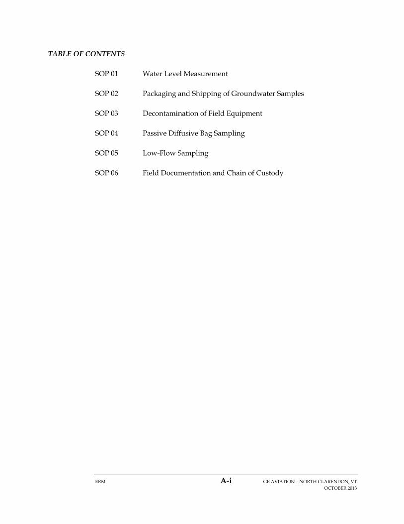
TABLE OF CONTENTS
SOP 01 Water Level Measurement
SOP 02 Packaging and Shipping of Groundwater Samples
SOP 03 Decontamination of Field Equipment
SOP 04 Passive Diffusive Bag Sampling
SOP 05 Low-Flow Sampling
SOP 06 Field Documentation and Chain of Custody

SOP 01
WATER LEVEL MEASUREMENT
ERM A-1 GE AVIATION – NORTH CLARENDON, VT OCTOBER 2013
1.0 PURPOSE
The purpose of this Standard Operating Procedure (SOP) is to describe the procedures to be used to collect groundwater elevation measurements. The measurements will be collected concurrent with the groundwater sampling event and prior to well evacuation and/or sample collection. The static water level will be measured to the nearest 0.01 foot.
2.0 EQUIPMENT AND MATERIALS
The following equipment will likely be used:
Tools for removing well cap;
Key for locking cap, if necessary;
Decontamination equipment (refer to SOP 03);
Water level meter;
Appropriate personal protective equipment (PPE);
Appropriate traffic protection equipment (e.g., traffic cones, barriers);
Field notebook; and
Site-specific Health & Safety Plan (HASP).
3.0 PROCEDURES
1. Clean all water-level measuring equipment using appropriate decontamination procedures.
2. Remove locking well cap, note weather, time of day, and date, etc. in field notebook, or on an appropriate form.
3. Remove well casing cap.
4. Lower water level measuring device into well until the water surface is encountered.
5. Measure depth to water surface from the reference measuring point on well casing, and record in field notebook.
6. Measure total depth of well and record in field notebook or on log form.

SOP 01
WATER LEVEL MEASUREMENT
ERM A-2 GE AVIATION – NORTH CLARENDON, VT OCTOBER 2013
7. Remove all downhole equipment; replace well casing cap and locking steel caps.
8. Calculate elevation of water:
Ew = E – D
Where: Ew = Elevation of water E = Elevation at point of measurement D = Depth to water

SOP 02
PACKAGING AND SHIPPING OF GROUNDWATER SAMPLES
ERM A-3 GE AVIATION – NORTH CLARENDON, VT OCTOBER 2013
1.0 PURPOSE
The purpose of this Standard Operating Procedure (SOP) is to describe the procedures to be used to package and ship all groundwater samples. These procedures are the recommended handling procedures for all sample shipments to minimize the loss of samples associated with breakage and/or being received above the method required temperature.
2.0 EQUIPMENT AND MATERIALS
The following equipment will likely be used:
Duct tape;
Clear packing tape;
Custody seals (provided by lab);
Closable plastic (or equivalent) bags, various sizes;
Packing material (packing peanuts, bubble wrap, etc.);
Ice;
Field notebook;
Mailing labels (in addition to any shipping papers); and
Site-specific Health & Safety Plan (HASP).
3.0 PROCEDURES
3.1 COOLERS
Coolers are the most common package or containment device used to ship samples. Coolers are also used during sampling efforts to store and transport samples prior to shipping. It is very important that samples be placed in an iced cooler immediately after collection. The ice in the cooler used for shipping will last much longer if the sample containers have been pre-chilled. The following procedures shall be used when packing the cooler for shipment:
Secure the drain on the cooler with packing tape or duct tape to prevent accidental opening.

SOP 02
PACKAGING AND SHIPPING OF GROUNDWATER SAMPLES
ERM A-4 GE AVIATION – NORTH CLARENDON, VT OCTOBER 2013
Place each individual sample in a closable plastic bag. Vials that are aliquots from the same sample can be placed in the same bag. It is recommended that the vials be wrapped with bubble wrap or paper towel to prevent excessive contact during shipping.
Place the samples into the cooler. Situate the sample containers so that they do not touch each other. This is very important for aqueous samples in glass containers as they are more prone to break.
Use plastic bubble wrap or packing peanuts as packing or filler material to prevent the samples from breaking during transportation. A thin layer of packing peanuts on the inside bottom of the cooler may help prevent breaking of the sample containers during transport. Avoid using shredded paper as packing material. Only a minimum amount of packing material should be used as these materials insulate the samples and prevent them from being properly chilled. Plastic sample containers or cardboard can be placed between glass containers. Bags of ice may be also be used as packaging material between samples. Sample containers should be snug and not easily moved within the cooler.
Fill the cooler with ice. Ice should be double-bagged in closable plastic bags. Forty to fifty percent of the cooler capacity should contain ice in order to keep the samples cold during transport. If a commercial carrier such as FedEx or UPS is shipping the samples, it is best to use more ice in case delivery is delayed. Less ice may be used if the samples will be delivered by hand.
Place the chain-of-custody (COC) record in a closable plastic bag and tape to the underside of the cooler lid.
Tape the cooler shut to prevent accidental opening or potential leakage. Tape shall be placed around the entire perimeter of the lid and then around the body of cooler. Do not tape down or otherwise restrict access to the cooler handles. Coolers used for shipping should not have any broken or missing handles.
Affix a mailing label with the laboratory’s address on the cooler. Apply clear tape over the address label to prevent accidental loss or damage during shipping. The label should be used in addition to any shipping papers required by carriers.
The temperature of the inside of the cooler will be measured by the laboratory upon receipt of the samples. If the cooler temperature is 4 degrees Celsius +/- 2 degrees Celsius then the cooler will be documented by the lab to have been received at an acceptable temperature. Cooler temperature readings will be noted in the laboratory report.

SOP 02
PACKAGING AND SHIPPING OF GROUNDWATER SAMPLES
ERM A-5 GE AVIATION – NORTH CLARENDON, VT OCTOBER 2013
4.0 DOCUMENTATION
A copy of any applicable shipping papers shall be retained for future reference. Any pertinent shipping information should be recorded in the field notebook.
SOP 03
DECONTAMINATION OF FIELD EQUIPMENT
ERM A-6 GE AVIATION – NORTH CLARENDON, VT OCTOBER 2013
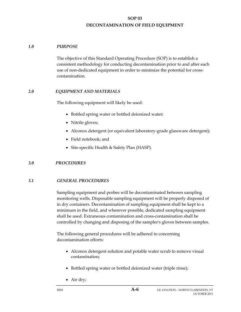
1.0 PURPOSE
The objective of this Standard Operating Procedure (SOP) is to establish a consistent methodology for conducting decontamination prior to and after each use of non-dedicated equipment in order to minimize the potential for cross-contamination.
2.0 EQUIPMENT AND MATERIALS
The following equipment will likely be used:
Bottled spring water or bottled deionized water;
Nitrile gloves;
Alconox detergent (or equivalent laboratory-grade glassware detergent);
Field notebook; and
Site-specific Health & Safety Plan (HASP).
3.0 PROCEDURES
3.1 GENERAL PROCEDURES
Sampling equipment and probes will be decontaminated between sampling monitoring wells. Disposable sampling equipment will be properly disposed of in dry containers. Decontamination of sampling equipment shall be kept to a minimum in the field, and wherever possible, dedicated sampling equipment shall be used. Extraneous contamination and cross-contamination shall be controlled by changing and disposing of the sampler's gloves between samples.
The following general procedures will be adhered to concerning decontamination efforts:
Alconox detergent solution and potable water scrub to remove visual contamination;
Bottled spring water or bottled deionized water (triple rinse);
Air dry;
SOP 03
DECONTAMINATION OF FIELD EQUIPMENT
ERM A-7 GE AVIATION – NORTH CLARENDON, VT OCTOBER 2013
If visual signs (such as discoloration) indicate that decontamination was insufficient, the equipment will again be decontaminated.

SOP 04
PASSIVE DIFFUSION BAG SAMPLING
ERM A-8 GE AVIATION – NORTH CLARENDON, VT OCTOBER 2013
1.0 PURPOSE
The purpose of this Standard Operating Procedure (SOP) is to establish a procedure for the use of polyethylene-based passive diffusion bag (PDB) samplers to obtain groundwater samples for analysis of volatile organic compounds (VOCs). PDBs are an alternative to low-flow and other traditional sampling techniques, accepted by the regulatory agencies. PDBs minimize the time for sampling and also minimize waste.
2.0 EQUIPMENT AND MATERIALS
The following equipment will likely be used:
One PDB per well to be sampled;
One harness per well to be sampled (labeled with well ID, with spool, wing-nuts and clips for securing PDBs set at appropriate locations for sampling depth (commonly, center of PDB is placed in-line with center of the saturated portion of the screen).
Polyethylene sheets (poly).
Water level indicator.
Miscellaneous tools – (e.g., wrench, well key, multi-tool, scissors, decontamination supplies, sample vials, coolers and ice);
Personal protective equipment (PPE);
Site plan showing well locations;
Chain-of-custody documentation;
Field notebook;
Site-specific Health & Safety Plan (HASP).
3.0 DEFINITIONS
Deionized (DI) Water – Water purified by passing through ion-exchange columns to remove all ions
Passive Diffusion Bag (PDB) – Low-density, polyethylene lay-flat tube closed at both ends filled with deionized water.
Well Harness – Used for securing PDB at appropriate depth inside well. Typically constructed using stainless steel (SS) wire with SS weight, SS clips

SOP 04
PASSIVE DIFFUSION BAG SAMPLING
ERM A-9 GE AVIATION – NORTH CLARENDON, VT OCTOBER 2013
secured at appropriate depth with SS wing nuts and plastic safety disc (disc) of greater diameter than well to prevent loss of harness
4.0 PROCEDURES
The following procedures shall be adhered to for groundwater sampling using PDBs.
4.1 PRE-ACTIVITIES – PDB PREPARATION Order pre-filled PDBs for sampling activities. Prior to first PDB sampling event, order well harness set-up with specifications from each monitoring well. Specifications for well harness set up include:
Well Identification;
Well diameter;
Total well depth;
Depth to top of screen;
Depth to bottom of screen; and
Desired depth to PDB.
4.2 PREPARE FOR DEPLOYMENT
Layout PDB, harness, and miscellaneous tools on appropriate sized poly. Open well, measure and record depth to water. Measure total depth and record. Lower the water level indicator slowly to
minimize sediment disturbance at the well bottom. Check well construction summary table to ensure screen has not silted. If screen is partially blocked, confirm with task manager that center of PDB location will need to be adjusted to be in-line with the center of the effective screen. Decontaminate water level indicator (SOP 03).
4.3 DEPLOYMENT Make sure the tether is connected to the spool so there is no chance of the
entire tether falling into the well.

SOP 04
PASSIVE DIFFUSION BAG SAMPLING
ERM A-10 GE AVIATION – NORTH CLARENDON, VT OCTOBER 2013
Securely attach the PBD to the tether using cable ties at the appropriate
depth.
o Stainless steel split rings will be attached to the tether at the depths provided to the vendor. Locate the small (1/2” diameter) stainless steel rings that are attached to the Tether line. The rings will be separated by the approximate length of the sampler. Use a cable-tie through the upper of two adjacent rings and through a section of mesh near the Fill Nozzle on the PDB. Use a second cable-tie through the lower of two adjacent rings and through the handle on the end of the Sampler. Tighten the cable-ties and snip off excess. Continue with each PDB.
Attach a weight to the bottom of the tether. Cut open the top and bottom of the outer plastic wrapper that is covering
the PDB.
Taking hold of PDB, lower harness in well starting with weight, then take hold of the top of PDB and wiring just above and lower continuing with PDB and finally lowering remaining wiring. NOTE: Lower PDB with as little contact with top of well casing or other objects (i.e., ground, roadbox) as possible to prevent contamination and to avoid puncturing bag. Lower set up slowly, especially when PDB comes in contact with and submerges in the water.
When weight touches bottom of well,
o Pull up on wiring to pick up on slack to where bottom of weight just touches the bottom of the well;
o Mark appropriate length on wiring to ensure that weight is not
caught on screen or other object but is at bottom of well. o Attach the top of the suspension cord to a well cap or other secure
location at the top of the well. Tighten expansion plug in place if applicable.
Lower the PDB and harness into the well. Leave the sampler in place for a
time suitable for equilibration (a minimum of 14 days). Attach the top of the suspension cord to a well cap or other secure location at the top of the well.

SOP 04
PASSIVE DIFFUSION BAG SAMPLING
ERM A-11 GE AVIATION – NORTH CLARENDON, VT OCTOBER 2013
4.4 QUALITY CONTROL & QUALITY ASSURANCE
Per recommendation of Interstate Technology Regulatory Council:
Collect duplicate sample from a single PDB sampler at a rate of one set of duplicates from every ten PDB samplers deployed (10%).
When PDBs are retrieved, visually inspect the bags and record observations including deposits, coatings or tears. Report any irregularities to task manager and record in field notebook.

SOP 05
LOW FLOW GROUNDWATER SAMPLING
ERM A-12 GE AVIATION – NORTH CLARENDON, VT OCTOBER 2013
1.0 PURPOSE
The objective of this Standard Operating Procedure (SOP) is to establish consistent methodology for collecting representative groundwater samples from monitoring wells while minimizing the amount of purge water generated. The goal of low-flow sampling is to purge a monitoring well at a similar or lower rate than recharge to the well, thereby obtaining samples that are representative of undisturbed groundwater. This technique involves pumping the groundwater at a low flow rate through a flow cell where water quality parameters are monitored until they stabilize, after which a groundwater sample is collected for laboratory analysis.
2.0 EQUIPMENT AND MATERIALS
The following equipment will likely be used:
Site-specific Health & Safety Plan (HASP);
Miscellaneous tools – (e.g., wrench, well key, multi-tool, scissors, decontamination supplies, sample vials, coolers and ice);
Adjustable-rate, low-flow, peristaltic pump (for water depth less than 28 feet);
Adjustable-rate, low-flow, submersible (for water depth greater than 28 feet);
Silicone tubing for peristaltic pump;
Teflon tubing, if dedicated to the well;
In-line, flow-through cell equipped with pH, oxidation reduction potential (ORP), dissolved oxygen (DO), specific conductivity and temperature electrodes;
Calibration solutions for pH, conductivity and ORP;
LaMotte 2020 Turbidimeter and 10 NTU calibration standard (only for biennial sampling events when sampling for nickel);
“T” fitting for collecting turbidity samples (only for biennial sampling events when sampling for nickel);
Electronic water-level indicator or equivalent (marked in 0.01-foot increments);
Field notebook, low-flow sampling forms and calibration forms;
SOP 05
LOW FLOW GROUNDWATER SAMPLING
ERM A-13 GE AVIATION – NORTH CLARENDON, VT OCTOBER 2013
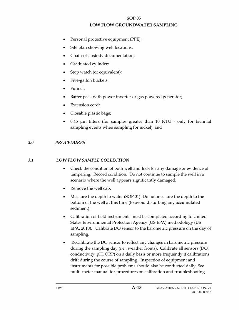
Personal protective equipment (PPE);
Site plan showing well locations;
Chain-of-custody documentation;
Graduated cylinder;
Stop watch (or equivalent);
Five-gallon buckets;
Funnel;
Batter pack with power inverter or gas powered generator;
Extension cord;
Closable plastic bags;
0.45 μm filters (for samples greater than 10 NTU - only for biennial sampling events when sampling for nickel); and
3.0 PROCEDURES
3.1 LOW FLOW SAMPLE COLLECTION
Check the condition of both well and lock for any damage or evidence of tampering. Record condition. Do not continue to sample the well in a scenario where the well appears significantly damaged.
Remove the well cap.
Measure the depth to water (SOP 01). Do not measure the depth to the bottom of the well at this time (to avoid disturbing any accumulated sediment).
Calibration of field instruments must be completed according to United States Environmental Protection Agency (US EPA) methodology (US EPA, 2010). Calibrate DO sensor to the barometric pressure on the day of sampling.
Recalibrate the DO sensor to reflect any changes in barometric pressure during the sampling day (i.e., weather fronts). Calibrate all sensors (DO, conductivity, pH, ORP) on a daily basis or more frequently if calibrations drift during the course of sampling. Inspection of equipment and instruments for possible problems should also be conducted daily. See multi-meter manual for procedures on calibration and troubleshooting

SOP 05
LOW FLOW GROUNDWATER SAMPLING
ERM A-14 GE AVIATION – NORTH CLARENDON, VT OCTOBER 2013
electrodes. Record the following information about each piece of equipment in the field notebook:
o Name of device and/or instrument calibrated;
o Device/instrument serial and/or identification number;
o Frequency of calibration;
o Date of calibration;
o Results of calibration; and
o Name of person performing the calibration.
Pre-measure the length of tubing so that the pump or tubing intake is set at approximately the middle of the screen. Avoid placing the pump intake less than 2 feet above the bottom of the well as this may cause mobilization of sediment present in the bottom of the well.
If using a peristaltic pump, slowly lower tubing into the well to desired pump intake depth. If using a submersible pump, attach and secure safety cable and tubing to the pump. Slowly lower pump into the well ti minimize disturbance of water in the well casing. If anything occurs to cause greater than minimal disturbance of the water column (e.g., slippage of the tubing) do not begin the sampling process. The water in the well must equilibrate before proceeding.
Start purging the well at the lowest possible rate. Avoid surging. Observe air bubbles displaced from discharge tube to assess progress of steady pumping until water arrives at the surface. Record the start time on the low-flow sampling form.
The water level in the well should be monitored during purging every three to five minutes and ideally the purge rate should equal the well recharge rate so that there is little or no drawdown in the well. (The water level should stabilize for the specific purge rate.) There should be at least one foot of water over the pump intake so there is no risk of the pump suction being broken, or entrainment of air in the sample. Record adjustments in the purge rate and changes in depth to water on the low-flow sampling form. Purge rates should, if needed, be decreased to the minimum capabilities of the pump to avoid affecting well drawdown. The well should not be purged dry. If the recharge rate of the well is so low that the well purges dry, the sample should be collected no earlier than two hours after purging and after enough water has recharged the well to fill the necessary sample bottles.

SOP 05
LOW FLOW GROUNDWATER SAMPLING
ERM A-15 GE AVIATION – NORTH CLARENDON, VT OCTOBER 2013
During well purging, use the flow-through cell to monitor the field parameters (temperature, pH, DO, ORP and specific conductivity) every three to five minutes depending on the size of the flow-through cell. The pump’s flow rate must be able to turn over at least one flow-through-cell well volume between measurements. When performing biennial sampling for nickel analysis, collect turbidity samples through the “T” fitting upstream of the flow cell every three to five minutes and record on the low-flow sampling form. Record the field parameters on the low-flow sampling form. Record the water level every three to five minutes. Record any odors and visual observations (i.e., water color) on the low flow form. The color should represent the final color of the water sampled and not the initial water pumped during purging. If the field parameters or drawdown fail to stabilize within two hours, contact the project manager for further instructions.
Monitor the flow-through cell to verify that there is no sediment accumulation and there is no gas bubble entrapment. The flow-through cell should be placed at a 45 degree angle with the port facing upwards to help remove any bubbles from the cell.
A sample should not be collected until the stabilization criteria listed below occur:
o Stabilization is achieved when three consecutive readings, taken at three to five minute intervals, are within the following limits:
Temperature (+/- 3%);
Specific conductance (+/- 3%);
pH (+/- 0.1 unit);
Turbidity (if collected) (< 5 NTU or +/- 10% for values greater than 5 NTU);
DO (<0.5 mg/l or +/- 10% for values greater than 0.5 mg/l);
ORP (+/- 10 millivolts).
o If the well purges dry in a low permeable formation, allow no less than two hours to pass for the well to recharge enough water to fill the necessary sample bottles.

SOP 05
LOW FLOW GROUNDWATER SAMPLING
ERM A-16 GE AVIATION – NORTH CLARENDON, VT OCTOBER 2013
Prior to sampling, disconnect the discharge tubing from the turbidity “T” valve (if used). Water samples should not be collected downstream of the flow-through cell. Continue pumping while flow-through cell is disconnected.
The sampling flow rate should not exceed 250 ml/min. If the pump’s flow rate is too high to collect the VOC samples, collect the other samples first, if any, then lower the pump’s flow rate to a reasonable rate and collect the VOC samples and record the new flow rate.
Samples for nickel analysis should be field filtered only if the final turbidity measurement exceeds 10 NTUs. If field filtering is required, then allow some sample water to pass through the filter before the sample is collected to allow equilibration of the water with the filter. Begin filling the filter with water so that the arrow is pointed upward, thereby displacing any air inside the filter that may affect redox sensitive elements (i.e., metals). After the filter has been conditioned turn the filter and begin collecting filtered samples. Make sure the arrow on the filter is vertically down as specified by the manufacturer. Also, if turbidity exceeds 10 NTUs, then an unfiltered metals sample will be collected along with the filtered sample to facilitate comparison of results.
Duplicate samples should be collected within series (i.e., VOC sample-VOC duplicate).
All sample bottles should be filled by allowing the water from the discharge tube to flow gently down the inside of the bottle with minimal turbulence. Cap each bottle as it is filled. Immediately place samples in a cooler filled with ice. Record sample completion time on the low flow sampling form and chain-of-custody.
The pump and/or tubing assembly should be carefully removed from the well. The tubing should be dedicated and remain in the well or stored in trash bags and properly labeled. Non-dedicated tubing should be disposed of between groundwater sampling events.
Measure and record the depth to the bottom of the well and note any evidence of sediment accumulation in the well.
Close and lock the well.
Battery packs for equipment should be charged overnight or when not in use. Multi-parameter meters should be stored overnight in a secure place near room temperature.
SOP 05
LOW FLOW GROUNDWATER SAMPLING
ERM A-17 GE AVIATION – NORTH CLARENDON, VT OCTOBER 2013
3.2 DECONTAMINATION
Decontaminate non-dedicated sampling equipment prior to use in the first well and following sampling of each subsequent well. The water level meter must be decontaminated. Teflon and silicone tubing dedicated to each well will be pulled out and placed in a separate plastic bags for storage on site. All parts of the equipment coming in contact with groundwater must be decontaminated by scrubbing thoroughly as described in SOP 03.
4.0 REFERENCES
US EPA, 2010. Standard Operating Procedure Calibration of Field Instruments, Quality Assurance Unit, US EPA – Region 1, 19 January 2010.
SOP 06
FIELD DOCUMENTATION AND CHAIN OF CUSTODY
ERM A-18 GE AVIATION – NORTH CLARENDON, VT OCTOBER 2013
1.0 PURPOSE
This Standard Operating Procedure (SOP) is applicable for the proper documentation of field activities and sample custody. All employees recording field notes should be aware that the field notebook is a legal document that can be heavily scrutinized. It is therefore the responsibility of the individual to record accurate and legible notes that permit the re-creation of field activities when the notebook is reviewed by other parties.
2.0 DEFINITIONS
Field Notebook is a legal document designed to track field activities.
Field Lead is the ERM employee assigned the leadership role during field activities.
Field Form is any form created to assist in the consistent collection of field data. The use of field forms must be referenced in the field book. Field forms are merely a supplement to the field book, not a replacement.
3.0 PROCEDURE
Field activities vary widely; however, it is the responsibility of the Field Lead to properly document activities, observations, conversations and any other event that affects field activities. Field notebooks are to be completed in a timely basis by the Field Lead or other designated responsible party.
3.1 General Practice
At the beginning of each field day, at a minimum, the following information must be entered into the field notebook.
o Names of personnel on site (initials are permissible for ERM personnel), names of contractors on site (first and last), and time of arrival and departure.
o A brief summary of the Tailgate Health and Safety Meeting, including attendees, topics covered and any issues or concerns that were raised.
SOP 06
FIELD DOCUMENTATION AND CHAIN OF CUSTODY
ERM A-19 GE AVIATION – NORTH CLARENDON, VT OCTOBER 2013
o A brief summary of anticipated activities for the day including details of any equipment and/or methods to be used.
o Current weather conditions – temperature, cloudiness, wind, precipitation. Note if there has been substantial precipitation in the last 24 hours or so, or if there is standing snow. If relevant to the project, note whether ground is frozen, wet, thickly vegetated, etc. Any changes in the weather conditions throughout the day must also be recorded.
General field notebook practices are as follows:
The first page of each logbook should contain a sign-in page. (Often the “table of contents” page is used.) All persons assigned to document site activities in the field notebook are required to complete this page. The sign-in page shall include a person’s printed name, signature, and initials. This page is completed to permit easier identification of signatures and initials within the field notebook.
Use permanent black ink.
The field notebook is intended for recording observations and recording data. Do not include opinions or interpretations within the field notebook.
There should not be blank pages or blank lines on a page. Use as much of each line and each page as is practical. No lines should be left blank in between field notebook entries. If you reserve a blank page for later use and end up not using it, draw a diagonal line across the page and initial.
If you make a mistake, draw a line through it such that it is still legible, initial the line, and write the correct information next to it (above, below).
Write the name of the client, project name/site, project number and date on top of each page.
Number the pages.
Initial the bottom of each page.
Observations from site walk. Note any changes to site since previous field notebook entry and current site conditions (e.g., damage to wells or equipment, new construction, things added to or removed from work area, evidence of trespassers, etc.).
SOP 06
FIELD DOCUMENTATION AND CHAIN OF CUSTODY
ERM A-20 GE AVIATION – NORTH CLARENDON, VT OCTOBER 2013
Names (first and last) of visitors entering and leaving the site, the times of arrival and departure, and purpose of visit.
Conversations, teleconferences or meetings with project manager, contractors, clients, regulators, etc. Record time, participants in discussion, topics discussed, any decisions made and who made them.
Use tables when practical to summarize and organize field data (e.g., depth to groundwater data).
If instruments are used, document the make, model and specifications and calibration activities (i.e., calibration standard used and instrument response).
Cross-reference any Quality Assurance/Quality Control samples collected (e.g., field duplicates, equipment blanks, trip blanks, etc.).
Beginnings and endings of lunch or breaks.
If field procedures or methods vary from SOPs or are modified on a project or activity basis, record which method is used each time.
4.0 CHAIN OF CUSTODY
A chain of custody (COC) record is the standard document to record important data associated with each individual sample. A COC is used to record three types of information: field information, laboratory information, and each field person who handled the sample.
Each sample container will be individually identified as to sample number, date and time taken, and source of sample. A COC record will be prepared for all samples which will include:
Name of the person collecting the samples;
Identity of each sample;
Source of each sample;
Preservation provisions for each sample;
Analytical requirements for each sample; and
SOP 06
FIELD DOCUMENTATION AND CHAIN OF CUSTODY
ERM A-21 GE AVIATION – NORTH CLARENDON, VT OCTOBER 2013
Name of person accepting the samples.
Custody transfers of samples will be recorded on the COC form by signatures of the relinquisher and the receiver. This procedure will be repeated, as necessary, until final delivery is made to the analytical laboratory.


![ENVIRONMENTAL COMPLIANCE MONITORING PLAN [PROJECT … · ENVIRONMENTAL COMPLIANCE MONITORING PLAN [PROJECT NAME] [RIGHT-OF-WAY GRANT NUMBER] For the [DISTRICT OFFICE NAME] ... ROD](https://img.dokumen.tips/doc/110x75/5eca3529eb69db4a884e10d5/environmental-compliance-monitoring-plan-project-environmental-compliance-monitoring.jpg)