Embed Size (px)
Citation preview

ENT345 Mechanical Components Design
Dr. Haftirman Mechanical Engineering Program School of Mechatronic Engineering Universiti Malaysia Perlis UniMAP Page 1
1) LOAD AND STRESS ANALYSIS
i. Principle stress
ii. The maximum shear stress
iii. The endurance strength of shaft.
1) Problem 3- 71
A countershaft carrying two-V belt pulleys is shown in the figure. Pulley A
receives power from a motor through a belt with the belt tensions shown.
The power is transmitted through the shaft and delivered to the belt on
pulley B. Assume the belt tension on the loose side at B is 15 percent of
the tension on the tight side.
a) Determine the tensions in the belt on pulley B, assuming the shaft is
running at a constant speed.
b) Find the magnitudes of the bearing reaction forces, assuming the
bearings act as simple supports.
c) Draw shear-force and bending moment diagrams for the shaft. If
needed, make one set for the horizontal plane and anther set for the
vertical plane.
d) At the point of maximum bending moment, determine the bending
stress and the torsional shear stress.
e) At the point of maximum bending moment, determine the principal
stresses and the maximum shear stress.
Solution
Assume the belt tension on the loose side at B is 15 percent of the tension on the
tight side. T2 = 0.15 T1

ENT345 Mechanical Components Design
Dr. Haftirman Mechanical Engineering Program School of Mechatronic Engineering Universiti Malaysia Perlis UniMAP Page 2
a) Determine the tensions in the belt on pulley B, assuming the shaft
is running at a constant speed.
∑𝑻 = 𝟎
(𝟑𝟎𝟎 − 𝟒𝟓)𝑵(𝟏𝟐𝟓)𝒎𝒎 + (𝑻𝟐 − 𝑻𝟏)𝑵(𝟏𝟓𝟎)𝒎𝒎 = 𝟎
𝟑𝟏𝟖𝟕𝟓𝑵𝒎𝒎 + (𝟎. 𝟏𝟓𝑻𝟏 − 𝑻𝟏)𝑵(𝟏𝟓𝟎)𝒎𝒎 = 𝟎
𝟑𝟏𝟖𝟕𝟓𝑵𝒎𝒎 − 𝟏𝟐𝟕. 𝟓𝑻𝟏 = 𝟎

ENT345 Mechanical Components Design
Dr. Haftirman Mechanical Engineering Program School of Mechatronic Engineering Universiti Malaysia Perlis UniMAP Page 3
𝑻𝟏 = 𝟐𝟓𝟎𝑵𝒎𝒎 On pulley B
𝑻𝟐 = (𝟎. 𝟏𝟓)𝟐𝟓𝟎𝑵𝒎𝒎 = 𝟑𝟕. 𝟓 𝑵𝒎𝒎
𝑻 = 𝑻𝟏 + 𝑻𝟐 = 𝟐𝟓𝟎 + 𝟑𝟕. 𝟓 = 𝟐𝟖𝟕. 𝟓 𝑵𝒎𝒎
b) Find the magnitudes of the bearing reaction forces, assuming the
bearings act as simple supports.
Y 31.82 N 45 N
31.82N T2=0.15 T1
X 212.132 N 300 N
A 45˚ B
Z 212.132 N
T1
∑𝑀𝑜𝑦 = 0
𝟑𝟒𝟓𝒄𝒐𝒔𝟒𝟓°(𝟑𝟎𝟎) − 𝟐𝟖𝟕. 𝟓(𝟕𝟎𝟎) + 𝑹𝑪𝒛(𝟖𝟓𝟎) = 𝟎
𝑹𝑪𝒛 = −𝟏𝟓𝟎. 𝟕 𝑵
∑𝐹𝑧 = 0
𝑹𝑶𝒛 − 𝟑𝟒𝟓𝒄𝒐𝒔𝟒𝟓° + 𝟐𝟖𝟕. 𝟓 − 𝟏𝟓𝟎. 𝟕 = 𝟎
𝑹𝑶𝒛 = 𝟏𝟎𝟕. 𝟐 𝑵
∑𝑀𝑜𝑧 = 0
𝟑𝟒𝟓𝒔𝒊𝒏𝟒𝟓°(𝟑𝟎𝟎) + 𝑹𝑪𝒚(𝟖𝟓𝟎) = 𝟎
𝑹𝑪𝒚 = −𝟖𝟔. 𝟏𝟎 𝑵

ENT345 Mechanical Components Design
Dr. Haftirman Mechanical Engineering Program School of Mechatronic Engineering Universiti Malaysia Perlis UniMAP Page 4
∑𝐹𝑦 = 0
𝑹𝑶𝒚 + 𝟑𝟒𝟓𝒄𝒐𝒔𝟒𝟓° − 𝟖𝟔. 𝟏𝟎 = 𝟎
𝑹𝑶𝒛 = −𝟏𝟓𝟕. 𝟗 𝑵
y 243.952
O A B C X
300 mm 400 mm 150 mm
-157.9 86.1

ENT345 Mechanical Components Design
Dr. Haftirman Mechanical Engineering Program School of Mechatronic Engineering Universiti Malaysia Perlis UniMAP Page 5
Z 243.952 150.7 N
O A B C X
300 mm 400 mm 150 mm
107.2 287.5
c) Draw shear-force and bending moment diagrams for the shaft. If
needed, make one set for the horizontal plane and anther set for
the vertical plane.
y 243.952
O A B C X
300 mm 400 mm 150 mm
-157.9 86.1
V (N)
86.1
O
-157.9

ENT345 Mechanical Components Design
Dr. Haftirman Mechanical Engineering Program School of Mechatronic Engineering Universiti Malaysia Perlis UniMAP Page 6
M (Nm)
O x
-47.37
Z 243.952 150.7 N
O A B C X
300 mm 400 mm 150 mm
107.2 287.5
V (N)
136.8
O
-107.2 150.7

ENT345 Mechanical Components Design
Dr. Haftirman Mechanical Engineering Program School of Mechatronic Engineering Universiti Malaysia Perlis UniMAP Page 7
M (Nm) 22.56
O x
-32.16
d) At the point of maximum bending moment, determine the bending
stress and the torsional shear stress.
The critical location is at A where both planes have the maximum
bending moment. Combining the bending moments from the two
planes;
𝑀 = √(−47.37)2 + (−32.16)2 = 57.26 𝑁𝑚
The torque transmitted through the shaft from A to B is
𝑇 = (300 − 45)(0.125) = 31.88 𝑁𝑚
The bending stress and the torsional stress are both maximum are on
the outer surface of a stress element.
𝜎 =𝑀𝑐
𝐼=
32𝑀
𝜋𝑑3=
32(57.26)
𝜋(0.020)3= 72.9𝑥106𝑃𝑎 = 72.9𝑀𝑃𝑎
𝜏 =𝑇𝑟
𝐽=
16𝑇
𝜋𝑑3=
16(31.88)
𝜋(0.020)3= 20.3𝑥106𝑃𝑎 = 20.3𝑀𝑃𝑎

ENT345 Mechanical Components Design
Dr. Haftirman Mechanical Engineering Program School of Mechatronic Engineering Universiti Malaysia Perlis UniMAP Page 8
e) At the point of maximum bending moment, determine the principal
stresses and the maximum shear stress.
𝜎1, 𝜎2 =𝜎𝑥
2± √(
𝜎𝑥
2)2
+ (𝜏𝑥𝑦)2
=72.9
2± √(
72.9
2)2
+ (20.3)2 =
𝜎1 = 78.2𝑀𝑃𝑎
𝜎2 = −5.27𝑀𝑃𝑎
𝜏𝑚𝑎𝑥 = √(𝜎𝑥
2)2
+ (𝜏𝑥𝑦)2
= √(72.9
2)2
+ (20.3)2 = 41.7 𝑀𝑃𝑎

ENT345 Mechanical Components Design
Dr. Haftirman Mechanical Engineering Program School of Mechatronic Engineering Universiti Malaysia Perlis UniMAP Page 9
2) Problem 3-73
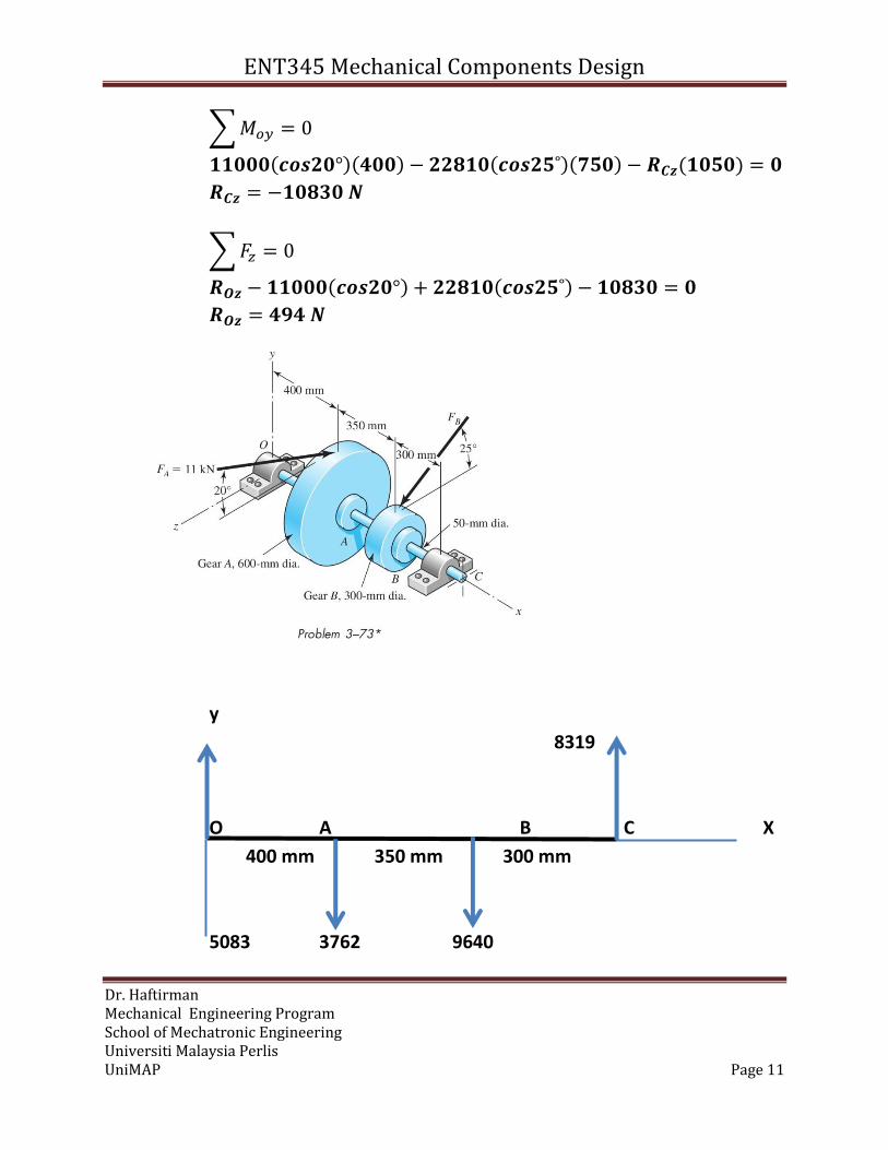
A gear reduction unit uses the countershaft shown in the figure. Gear A
receives power from another gear with the transmitted force FA applied at
the 20˚ pressure angle as shown. The power is transmitted through the shaft
and delivered through gear B through a transmitted force FB at the pressure
angle shown.
a) Determine the force FB, assuming the shaft is running at a constant
speed.
b) Find the magnitudes of the bearing reaction forces, assuming the
bearings act as simple supports.
c) Draw shear-force and bending-moment diagrams for the shaft. If
needed, make one set for the horizontal plane and another set for the
vertical plane.
d) At the point of maximum bending moment, determine the bending
stress and the torsional shear stress.
e) At the point of maximum bending moment, determine the principal
stresses and the maximum shear stress.

ENT345 Mechanical Components Design
Dr. Haftirman Mechanical Engineering Program School of Mechatronic Engineering Universiti Malaysia Perlis UniMAP Page 10
FB
Y FA
20˚ 25˚
Z
a) Determine the force FB, assuming the shaft is running at a constant
speed.
∑𝑻 = 𝟎
−𝟏𝟏𝟎𝟎𝟎(𝒄𝒐𝒔𝟐𝟎°)(𝟑𝟎𝟎) − 𝑭𝑩(𝒄𝒐𝒔𝟐𝟓°)(𝟏𝟓𝟎) = 𝟎
𝑭𝑩 = 𝟐𝟐𝟖𝟏𝟎 𝑵
b) Find the magnitudes of the bearing reaction forces, assuming the
bearings act as simple supports.
∑𝑀𝑜𝑧 = 0
−𝟏𝟏𝟎𝟎𝟎(𝒔𝒊𝒏𝟐𝟎°)(𝟒𝟎𝟎) − 𝟐𝟐𝟖𝟏𝟎(𝒔𝒊𝒏𝟐𝟓˚)(𝟕𝟓𝟎) + 𝑹𝑪𝒚(𝟏𝟎𝟓𝟎)
= 𝟎
𝑹𝑪𝒚 = 𝟖𝟑𝟏𝟗 𝑵
∑𝐹𝑦 = 0
𝑹𝑶𝒚 − 𝟏𝟏𝟎𝟎𝟎(𝒔𝒊𝒏𝟐𝟎°) − 𝟐𝟐𝟖𝟏𝟎(𝒔𝒊𝒏𝟐𝟓˚) + 𝟖𝟑𝟏𝟗 = 𝟎
𝑹𝑶𝒚 = 𝟓𝟎𝟖𝟑 𝑵
ENT345 Mechanical Components Design
Dr. Haftirman Mechanical Engineering Program School of Mechatronic Engineering Universiti Malaysia Perlis UniMAP Page 11
∑𝑀𝑜𝑦 = 0
𝟏𝟏𝟎𝟎𝟎(𝒄𝒐𝒔𝟐𝟎°)(𝟒𝟎𝟎) − 𝟐𝟐𝟖𝟏𝟎(𝒄𝒐𝒔𝟐𝟓˚)(𝟕𝟓𝟎) − 𝑹𝑪𝒛(𝟏𝟎𝟓𝟎) = 𝟎
𝑹𝑪𝒛 = −𝟏𝟎𝟖𝟑𝟎 𝑵
∑𝐹𝑧 = 0
𝑹𝑶𝒛 − 𝟏𝟏𝟎𝟎𝟎(𝒄𝒐𝒔𝟐𝟎°) + 𝟐𝟐𝟖𝟏𝟎(𝒄𝒐𝒔𝟐𝟓˚) − 𝟏𝟎𝟖𝟑𝟎 = 𝟎
𝑹𝑶𝒛 = 𝟒𝟗𝟒 𝑵
y
8319
O A B C X
400 mm 350 mm 300 mm
5083 3762 9640

ENT345 Mechanical Components Design
Dr. Haftirman Mechanical Engineering Program School of Mechatronic Engineering Universiti Malaysia Perlis UniMAP Page 12
Z 10337 10830
O A B C X
400 mm 350 mm 300 mm
494 20673
c) Draw shear-force and bending-moment diagrams for the shaft. If
needed, make one set for the horizontal plane and another set for
the vertical plane.
d)
V (N)
5083
1321
O
-8319
M (Nm)
2496 x
2033
-47.37
V (N) 9843

ENT345 Mechanical Components Design
Dr. Haftirman Mechanical Engineering Program School of Mechatronic Engineering Universiti Malaysia Perlis UniMAP Page 13
O
-494
-10830
M (Nm) 3249
O
-198
d) At the point of maximum bending moment, determine the bending
stress and the torsional shear stress.
The critical location is at B where both planes have the maximum
bending moment. Combining the bending moments from the two
planes;
𝑀 = √(2496)2 + (3249)2 = 4097 𝑁𝑚
The torque transmitted through the shaft from A to B is
𝑇 = 11000(𝑐𝑜𝑠20°)(0.3) = 3101 𝑁𝑚
The bending stress and the torsional stress are both maximum are on
the outer surface of a stress element.

ENT345 Mechanical Components Design
Dr. Haftirman Mechanical Engineering Program School of Mechatronic Engineering Universiti Malaysia Perlis UniMAP Page 14
𝜎 =𝑀𝑐
𝐼=
32𝑀
𝜋𝑑3=
32(4097)
𝜋(0.050)3= 333.9𝑥106𝑃𝑎 = 333.9𝑀𝑃𝑎
𝜏 =𝑇𝑟
𝐽=
16𝑇
𝜋𝑑3=
16(3101)
𝜋(0.050)3= 126𝑥106𝑃𝑎 = 20.3𝑀𝑃𝑎
e) At the point of maximum bending moment, determine the principal
stresses and the maximum shear stress.
𝜎1, 𝜎2 =𝜎𝑥
2± √(
𝜎𝑥
2)2
+ (𝜏𝑥𝑦)2
=333.9
2± √(
333.9
2)2
+ (126.3)2
=
𝜎1 = 376𝑀𝑃𝑎
𝜎2 = −42.4𝑀𝑃𝑎
𝜏𝑚𝑎𝑥 = √(𝜎𝑥
2)2
+ (𝜏𝑥𝑦)2
= √(333.9
2)2
+ (126.3)2 = 209 𝑀𝑃𝑎
f) The endurance strength of the shaft:
Material: AISI 1040 CD with Sut = 590 MPa
Diameter of shaft: d = 50 mm
Machined or cold-drawn a = 4.51 and b = - 0.265
S𝑒′ = 0.5(590) = 295 𝑀𝑃𝑎
𝑘𝑎 = 𝑎𝑆𝑢𝑡𝑏 = (4.51)(590)−0.265 = 0.83157
Surface factor ka =0.83157
The loading situation is rotating bending.
𝑘𝑏 = (𝑑
7.62)−0.107
= (50
7.62)−0.107
= 0.8176
𝑺𝒆 = 𝒌𝒂𝒌𝒃𝑺𝒆′ = (𝟎. 𝟖𝟑𝟏𝟓𝟕)(𝟎. 𝟖𝟏𝟕𝟔)(𝟐𝟗𝟓) = 𝟐𝟎𝟎. 𝟓𝟔𝟖𝑴𝑷𝒂.
The endurance strength is Se = 200.568 MPa

ENT345 Mechanical Components Design
Dr. Haftirman Mechanical Engineering Program School of Mechatronic Engineering Universiti Malaysia Perlis UniMAP Page 15
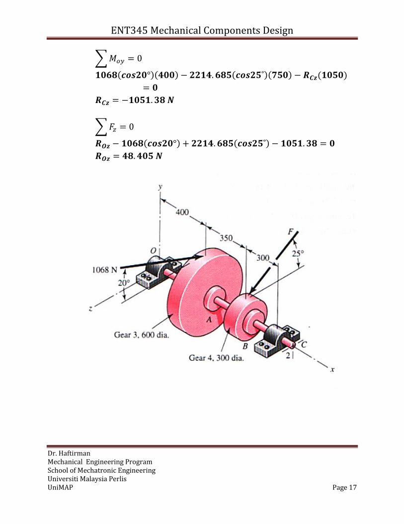
3) Problem 11-34
A gear-reduction unit uses the countershaft depicted in figure.
Find the two bearing reactions. The bearings are to be angular-contact ball
bearings, having a desired life of 40 kh when used at 200 rev/min. Use 1.2
for the application factor and a reliability goal for the bearing pair of 0.95.
Select the bearings from Table 11-2
Solution

ENT345 Mechanical Components Design
Dr. Haftirman Mechanical Engineering Program School of Mechatronic Engineering Universiti Malaysia Perlis UniMAP Page 16
FB
Y FA
20˚ 25˚
Z
b) Determine the force FB, assuming the shaft is running at a constant
speed.
∑𝑻 = 𝟎
−𝟏𝟎𝟔𝟖(𝒄𝒐𝒔𝟐𝟎°)(𝟑𝟎𝟎) − 𝑭𝑩(𝒄𝒐𝒔𝟐𝟓°)(𝟏𝟓𝟎) = 𝟎
𝑭𝑩 = 𝟐𝟐𝟏𝟒. 𝟔𝟖𝟓 𝑵
c) Find the magnitudes of the bearing reaction forces, assuming the
bearings act as simple supports.
∑𝑀𝑜𝑧 = 0
−𝟏𝟎𝟔𝟖(𝒔𝒊𝒏𝟐𝟎°)(𝟒𝟎𝟎) − 𝟐𝟐𝟏𝟒. 𝟔𝟖𝟓(𝒔𝒊𝒏𝟐𝟓˚)(𝟕𝟓𝟎) + 𝑹𝑪𝒚(𝟏𝟎𝟓𝟎)
= 𝟎
𝑹𝑪𝒚 = 𝟖𝟎𝟕. 𝟕𝟎𝟎 𝑵
∑𝐹𝑦 = 0
𝑹𝑶𝒚 − 𝟏𝟎𝟔𝟖(𝒔𝒊𝒏𝟐𝟎°) − 𝟐𝟐𝟏𝟒. 𝟔𝟖𝟓(𝒔𝒊𝒏𝟐𝟓˚) + 𝟖𝟎𝟕. 𝟕𝟎𝟎 = 𝟎
𝑹𝑶𝒚 = 𝟒𝟗𝟑. 𝟓𝟒𝟑 𝑵
ENT345 Mechanical Components Design
Dr. Haftirman Mechanical Engineering Program School of Mechatronic Engineering Universiti Malaysia Perlis UniMAP Page 17
∑𝑀𝑜𝑦 = 0
𝟏𝟎𝟔𝟖(𝒄𝒐𝒔𝟐𝟎°)(𝟒𝟎𝟎) − 𝟐𝟐𝟏𝟒. 𝟔𝟖𝟓(𝒄𝒐𝒔𝟐𝟓˚)(𝟕𝟓𝟎) − 𝑹𝑪𝒛(𝟏𝟎𝟓𝟎)
= 𝟎
𝑹𝑪𝒛 = −𝟏𝟎𝟓𝟏. 𝟑𝟖 𝑵
∑𝐹𝑧 = 0
𝑹𝑶𝒛 − 𝟏𝟎𝟔𝟖(𝒄𝒐𝒔𝟐𝟎°) + 𝟐𝟐𝟏𝟒. 𝟔𝟖𝟓(𝒄𝒐𝒔𝟐𝟓˚) − 𝟏𝟎𝟓𝟏. 𝟑𝟖 = 𝟎
𝑹𝑶𝒛 = 𝟒𝟖. 𝟒𝟎𝟓 𝑵
ENT345 Mechanical Components Design
Dr. Haftirman Mechanical Engineering Program School of Mechatronic Engineering Universiti Malaysia Perlis UniMAP Page 18
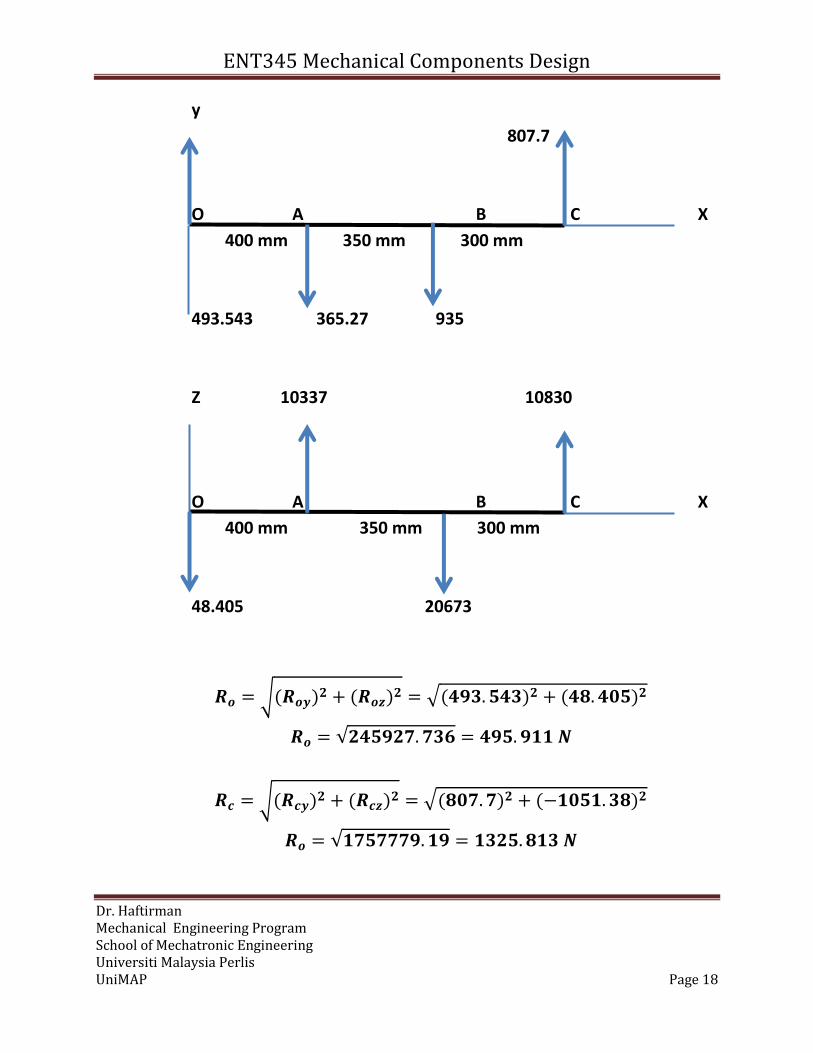
y
807.7
O A B C X
400 mm 350 mm 300 mm
493.543 365.27 935
Z 10337 10830
O A B C X
400 mm 350 mm 300 mm
48.405 20673
𝑹𝒐 = √(𝑹𝒐𝒚)𝟐 + (𝑹𝒐𝒛)
𝟐 = √(𝟒𝟗𝟑. 𝟓𝟒𝟑)𝟐 + (𝟒𝟖. 𝟒𝟎𝟓)𝟐
𝑹𝒐 = √𝟐𝟒𝟓𝟗𝟐𝟕. 𝟕𝟑𝟔 = 𝟒𝟗𝟓. 𝟗𝟏𝟏 𝑵
𝑹𝒄 = √(𝑹𝒄𝒚)𝟐 + (𝑹𝒄𝒛)
𝟐 = √(𝟖𝟎𝟕. 𝟕)𝟐 + (−𝟏𝟎𝟓𝟏. 𝟑𝟖)𝟐
𝑹𝒐 = √𝟏𝟕𝟓𝟕𝟕𝟕𝟗. 𝟏𝟗 = 𝟏𝟑𝟐𝟓. 𝟖𝟏𝟑 𝑵

ENT345 Mechanical Components Design
Dr. Haftirman Mechanical Engineering Program School of Mechatronic Engineering Universiti Malaysia Perlis UniMAP Page 19
𝑭𝑫𝑶 = (𝟏. 𝟐)(𝟒𝟗𝟓. 𝟗𝟏𝟏) = 𝟓𝟗𝟓. 𝟎𝟗𝟑 𝑵
𝑭𝑫𝑪 = (𝟏. 𝟐)(𝟏𝟑𝟐𝟓. 𝟖𝟏𝟑) = 𝟏𝟓𝟗𝟎. 𝟗𝟕 𝑵
𝒙𝑫 =𝑳𝑫𝒏𝑫𝟔𝟎
𝑳𝑹𝒏𝑹𝟔𝟎=
(𝟒𝟎𝟎𝟎𝟎)(𝟐𝟎𝟎)(𝟔𝟎)
(𝟏𝟎𝟔)= 𝟒𝟖𝟎
Realibility for RA and RB are √R = √0.95 = 0.975
(𝐶10)𝑂 = 595.093
[
480
0.02 + 4.439 [𝑙𝑛 (1
0.975)]
11.483
]
13
= 6351.465 𝑁
Bearing Type is angular contact bearing at O, series number 02- 12
Bore : 12 mm
OD : 32 mm
Width : 10 mm
Fillet radius : 0.6 mm
Shoulder diameter: ds = 14.5 mm, dH= 28 mm
(𝐶10)𝑂 = 1590.97
[
480
0.02 + 4.439 [𝑙𝑛 (1
0.975)]
11.483
]
13
= 16980.522 𝑁
Bearing Type is angular contact bearing at C, series number 02- 30
Bore : 30 mm
OD : 62 mm
Width : 16 mm
Fillet radius : 1.0 mm
Shoulder diameter: ds = 35 mm, dH= 55 mm