Embed Size (px)
Citation preview
DR. HAFTIRMAN
School of Mechatronic
UniMAP
ENT345 MECHANICAL COMPONENTS
DESIGN SEM1-2015/2016
1
LECTURE NOTES
ENT345
ROLLING-CONTACT BEARINGS
Lecture 13
10/12/2015
Dr. HAFTIRMAN
MECHANICAL ENGINEEERING PROGRAM
SCHOOL OF MECHATRONIC ENGINEERING
UniMAP
COPYRIGHT©RESERVED 2015

http://goo.gl/forms/dpPWlohs9F
DR. HAFTIRMAN
School of Mechatronic UniMAP
ENT345 MECHANICAL COMPONENTS
DESIGN SEM1-2015/2016
2
Rolling-contact bearings
CO3:
ABILITY TO EVALUATE
MECHANICAL COMPONENTS FOR
SELECTED MECHANICAL SYSTEMS
DR. HAFTIRMAN
School of Mechatronic UniMAP
ENT345 MECHANICAL COMPONENTS
DESIGN SEM1-2015/2016
3
DR. HAFTIRMAN
School of Mechatronic UniMAP
ENT345 MECHANICAL COMPONENTS
DESIGN SEM1-2015/2016
4
Outline
Bearing types
Bearing life
Bearing load life at rated reliability
Bearing survival: reliability versus life
Relating load, life, and reliability
Combined radial and thrust loading.
Variable loading
Selection of ball and cylindrical roller bearings
Selection of tapered roller bearings
Design assessment for selected rolling-contact bearings.
DR. HAFTIRMAN
School of Mechatronic UniMAP
5 ENT345 MECHANICAL COMPONENTS
DESIGN SEM1-2015/2016
DR. HAFTIRMAN
School of Mechatronic UniMAP
6 ENT345 MECHANICAL COMPONENTS
DESIGN SEM1-2015/2016
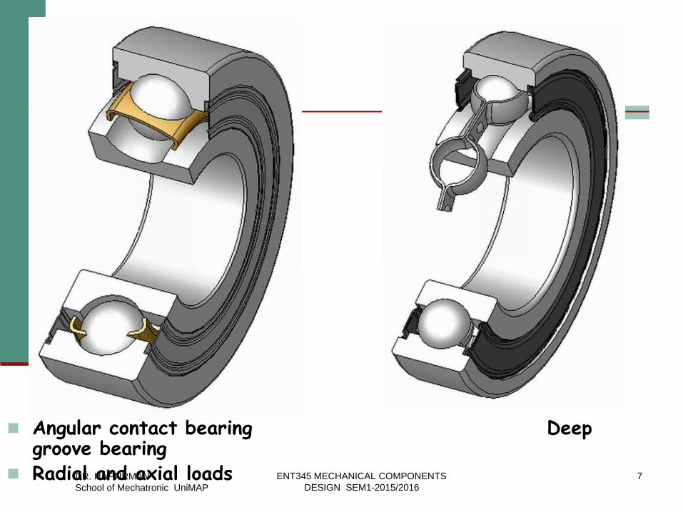
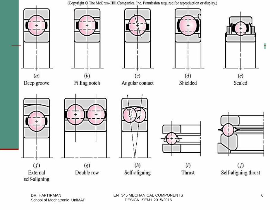
Angular contact bearing Deep
groove bearing Radial and axial loads DR. HAFTIRMAN
School of Mechatronic UniMAP
7 ENT345 MECHANICAL COMPONENTS
DESIGN SEM1-2015/2016
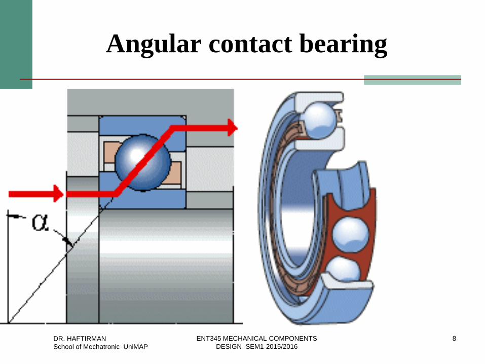
Angular contact bearing
DR. HAFTIRMAN
School of Mechatronic UniMAP
8 ENT345 MECHANICAL COMPONENTS
DESIGN SEM1-2015/2016
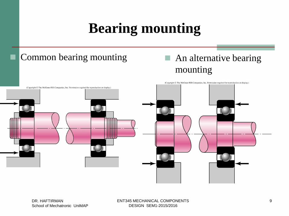
Bearing mounting
Common bearing mounting An alternative bearing
mounting
DR. HAFTIRMAN
School of Mechatronic UniMAP
9 ENT345 MECHANICAL COMPONENTS
DESIGN SEM1-2015/2016
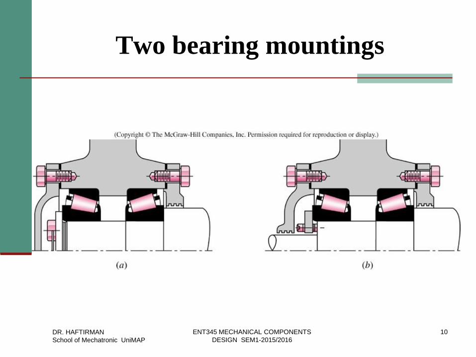
Two bearing mountings
DR. HAFTIRMAN
School of Mechatronic UniMAP
10 ENT345 MECHANICAL COMPONENTS
DESIGN SEM1-2015/2016
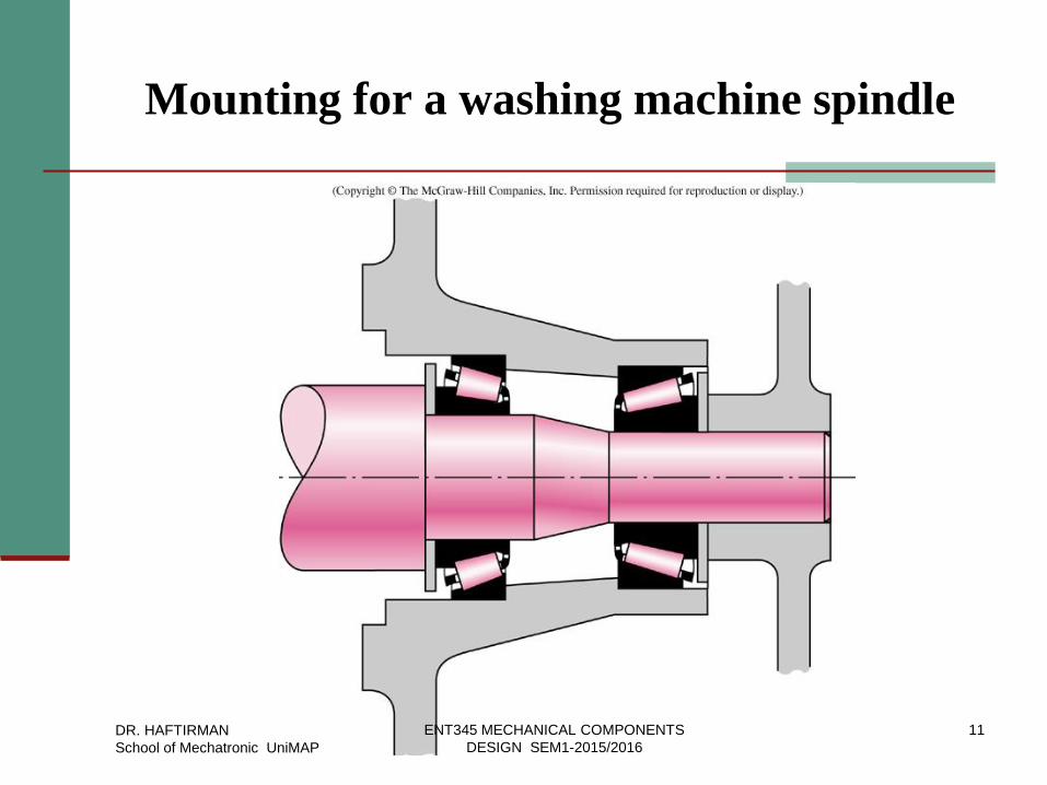
Mounting for a washing machine spindle
DR. HAFTIRMAN
School of Mechatronic UniMAP
11 ENT345 MECHANICAL COMPONENTS
DESIGN SEM1-2015/2016
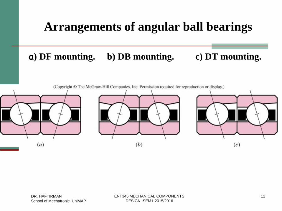
Arrangements of angular ball bearings
a) DF mounting. b) DB mounting. c) DT mounting.
DR. HAFTIRMAN
School of Mechatronic UniMAP
12 ENT345 MECHANICAL COMPONENTS
DESIGN SEM1-2015/2016
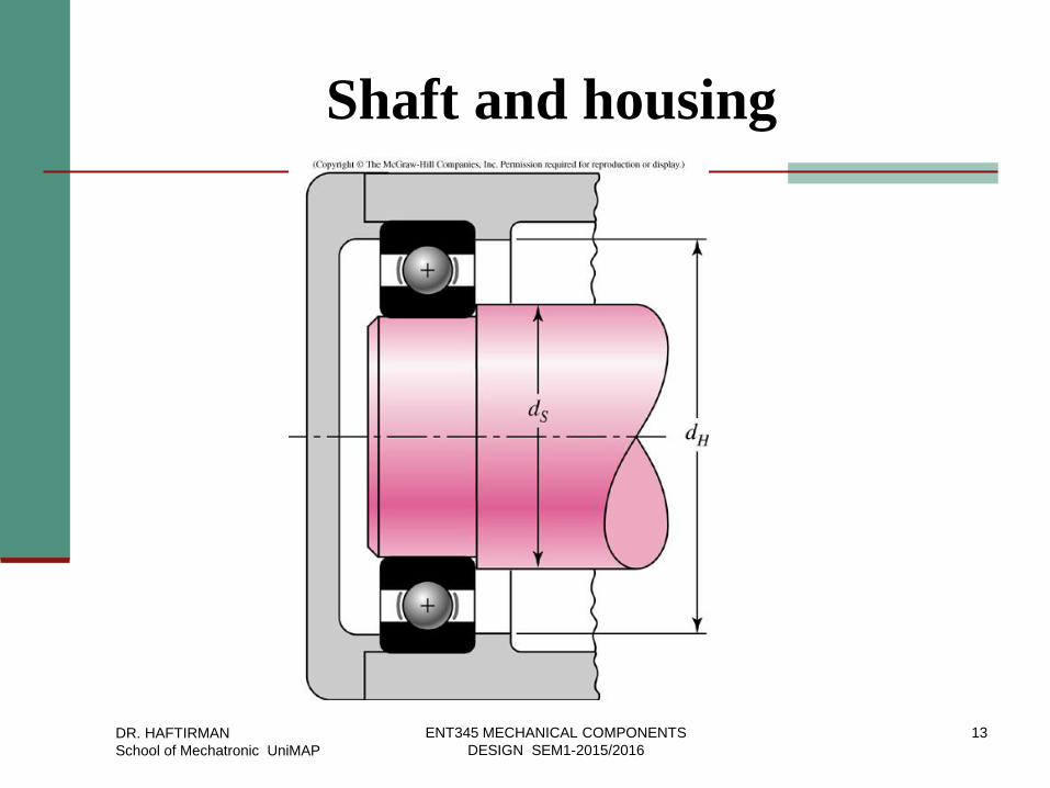
Shaft and housing
DR. HAFTIRMAN
School of Mechatronic UniMAP
13 ENT345 MECHANICAL COMPONENTS
DESIGN SEM1-2015/2016
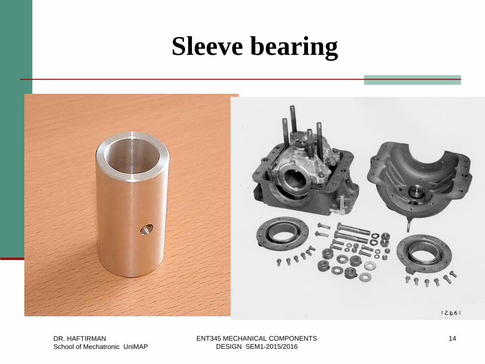
Sleeve bearing
DR. HAFTIRMAN
School of Mechatronic UniMAP
14 ENT345 MECHANICAL COMPONENTS
DESIGN SEM1-2015/2016
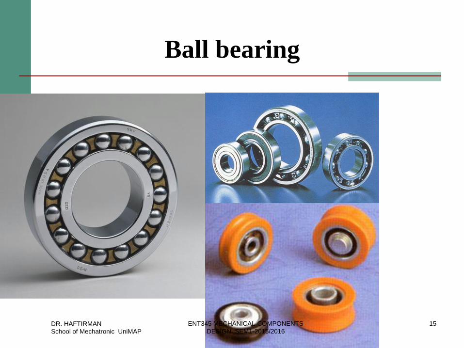
Ball bearing
DR. HAFTIRMAN
School of Mechatronic UniMAP
15 ENT345 MECHANICAL COMPONENTS
DESIGN SEM1-2015/2016
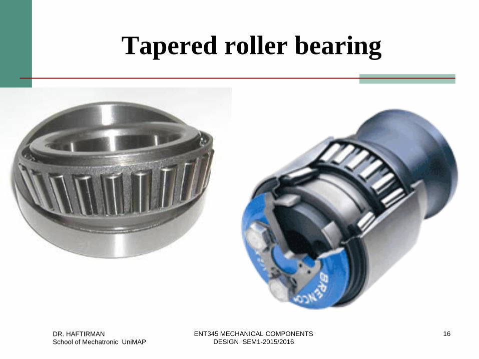
Tapered roller bearing
DR. HAFTIRMAN
School of Mechatronic UniMAP
16 ENT345 MECHANICAL COMPONENTS
DESIGN SEM1-2015/2016
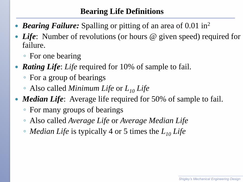
Bearing Life Definitions
Bearing Failure: Spalling or pitting of an area of 0.01 in2
Life: Number of revolutions (or hours @ given speed) required for failure.
◦ For one bearing
Rating Life: Life required for 10% of sample to fail.
◦ For a group of bearings
◦ Also called Minimum Life or L10 Life
Median Life: Average life required for 50% of sample to fail.
◦ For many groups of bearings
◦ Also called Average Life or Average Median Life
◦ Median Life is typically 4 or 5 times the L10 Life
Shigley’s Mechanical Engineering Design
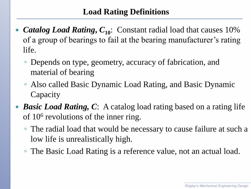
Load Rating Definitions
Catalog Load Rating, C10: Constant radial load that causes 10%
of a group of bearings to fail at the bearing manufacturer’s rating
life.
◦ Depends on type, geometry, accuracy of fabrication, and
material of bearing
◦ Also called Basic Dynamic Load Rating, and Basic Dynamic
Capacity
Basic Load Rating, C: A catalog load rating based on a rating life
of 106 revolutions of the inner ring.
◦ The radial load that would be necessary to cause failure at such a
low life is unrealistically high.
◦ The Basic Load Rating is a reference value, not an actual load.
Shigley’s Mechanical Engineering Design
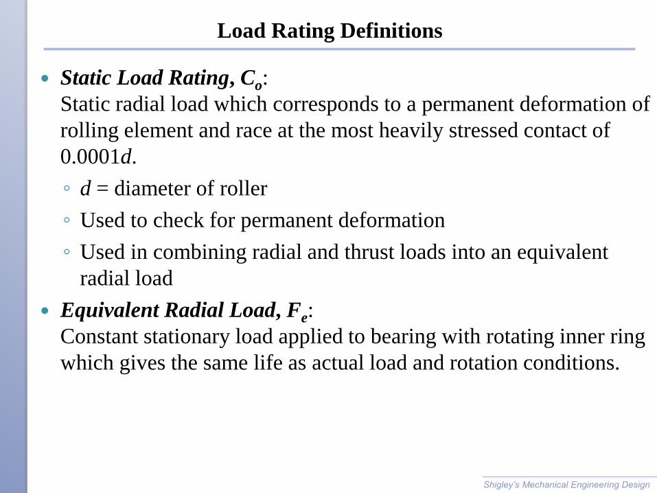
Load Rating Definitions
Static Load Rating, Co:
Static radial load which corresponds to a permanent deformation of
rolling element and race at the most heavily stressed contact of
0.0001d.
◦ d = diameter of roller
◦ Used to check for permanent deformation
◦ Used in combining radial and thrust loads into an equivalent
radial load
Equivalent Radial Load, Fe:
Constant stationary load applied to bearing with rotating inner ring
which gives the same life as actual load and rotation conditions.
Shigley’s Mechanical Engineering Design
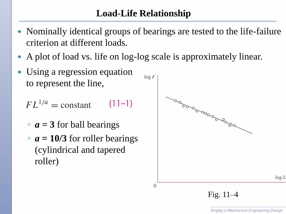
Using a regression equation
to represent the line,
◦ a = 3 for ball bearings
◦ a = 10/3 for roller bearings
(cylindrical and tapered
roller)
Load-Life Relationship
Nominally identical groups of bearings are tested to the life-failure
criterion at different loads.
A plot of load vs. life on log-log scale is approximately linear.
Shigley’s Mechanical Engineering Design
Fig. 11–4
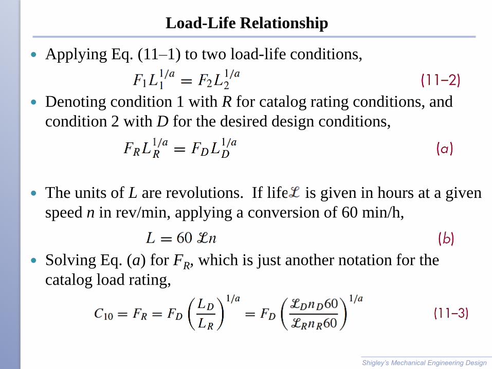
Load-Life Relationship
Applying Eq. (11–1) to two load-life conditions,
Denoting condition 1 with R for catalog rating conditions, and
condition 2 with D for the desired design conditions,
The units of L are revolutions. If life is given in hours at a given
speed n in rev/min, applying a conversion of 60 min/h,
Solving Eq. (a) for FR, which is just another notation for the
catalog load rating,
Shigley’s Mechanical Engineering Design
Load-Life Relationship
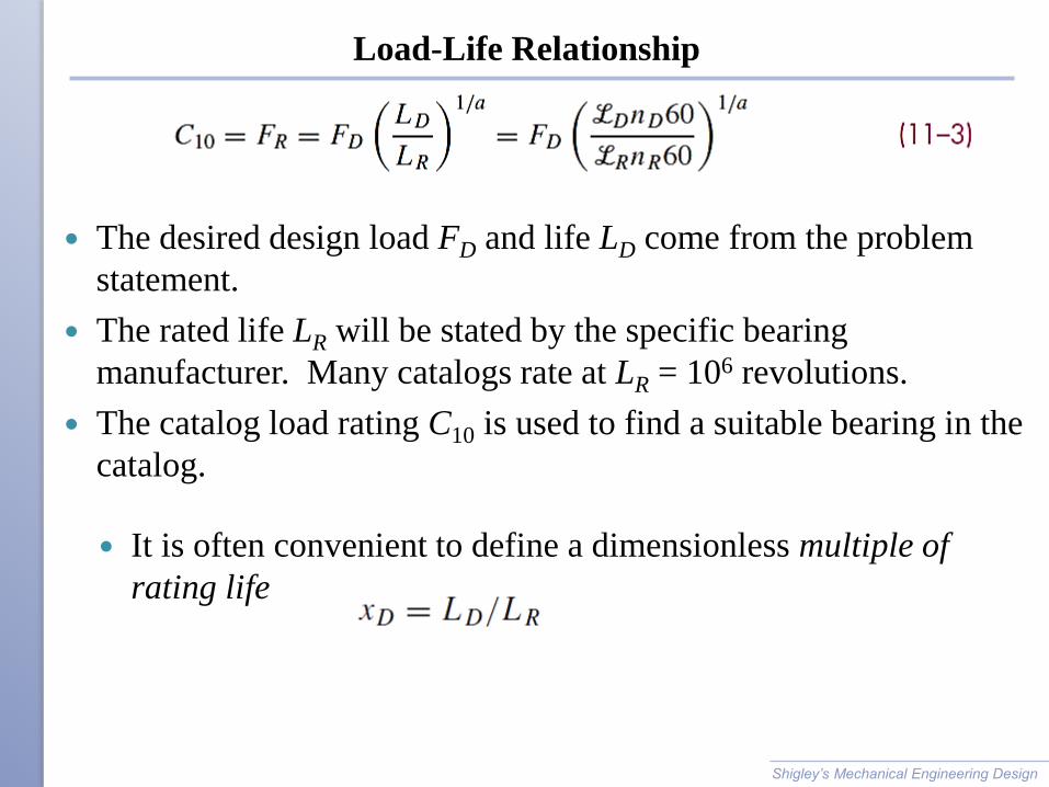
The desired design load FD and life LD come from the problem
statement.
The rated life LR will be stated by the specific bearing
manufacturer. Many catalogs rate at LR = 106 revolutions.
The catalog load rating C10 is used to find a suitable bearing in the
catalog.
Shigley’s Mechanical Engineering Design
It is often convenient to define a dimensionless multiple of
rating life
Example 11-1
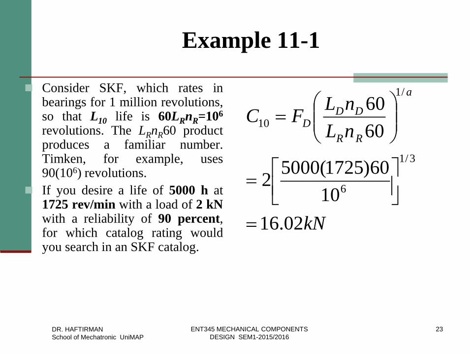
Consider SKF, which rates in bearings for 1 million revolutions, so that L10 life is 60LRnR=106
revolutions. The LRnR60 product produces a familiar number. Timken, for example, uses 90(106) revolutions.
If you desire a life of 5000 h at 1725 rev/min with a load of 2 kN with a reliability of 90 percent, for which catalog rating would you search in an SKF catalog.
kN
nL
nLFC
a
RR
DDD
02.16
10
60)1725(50002
60
60
3/1
6
/1
10
DR. HAFTIRMAN
School of Mechatronic UniMAP
23 ENT345 MECHANICAL COMPONENTS
DESIGN SEM1-2015/2016
Relating Load, Life, and Reliability
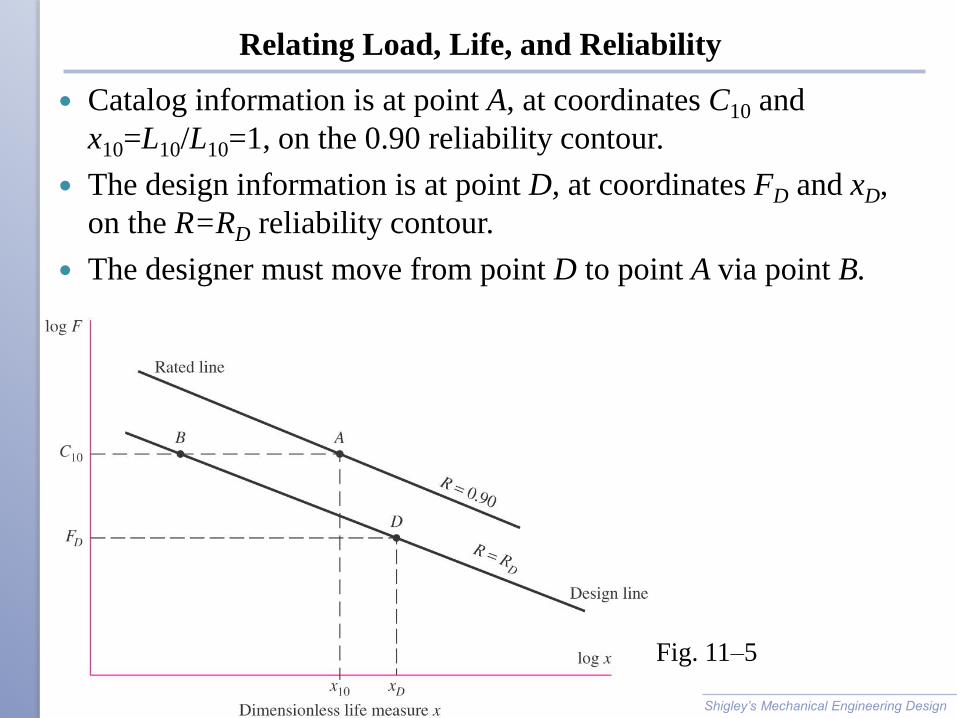
Catalog information is at point A, at coordinates C10 and
x10=L10/L10=1, on the 0.90 reliability contour.
The design information is at point D, at coordinates FD and xD,
on the R=RD reliability contour.
The designer must move from point D to point A via point B.
Shigley’s Mechanical Engineering Design
Fig. 11–5
Relating Load, Life, and Reliability
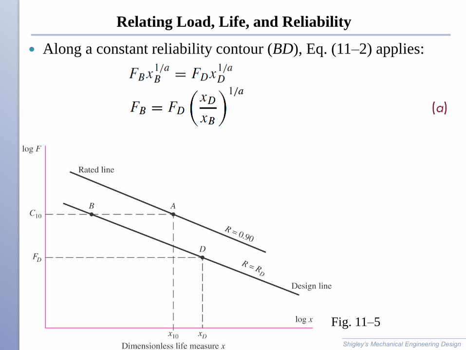
Along a constant reliability contour (BD), Eq. (11–2) applies:
Shigley’s Mechanical Engineering Design
Fig. 11–5
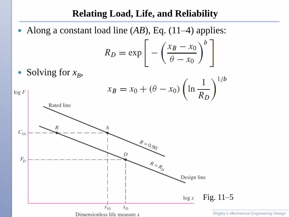
Relating Load, Life, and Reliability
Along a constant load line (AB), Eq. (11–4) applies:
Solving for xB,
Shigley’s Mechanical Engineering Design
Fig. 11–5
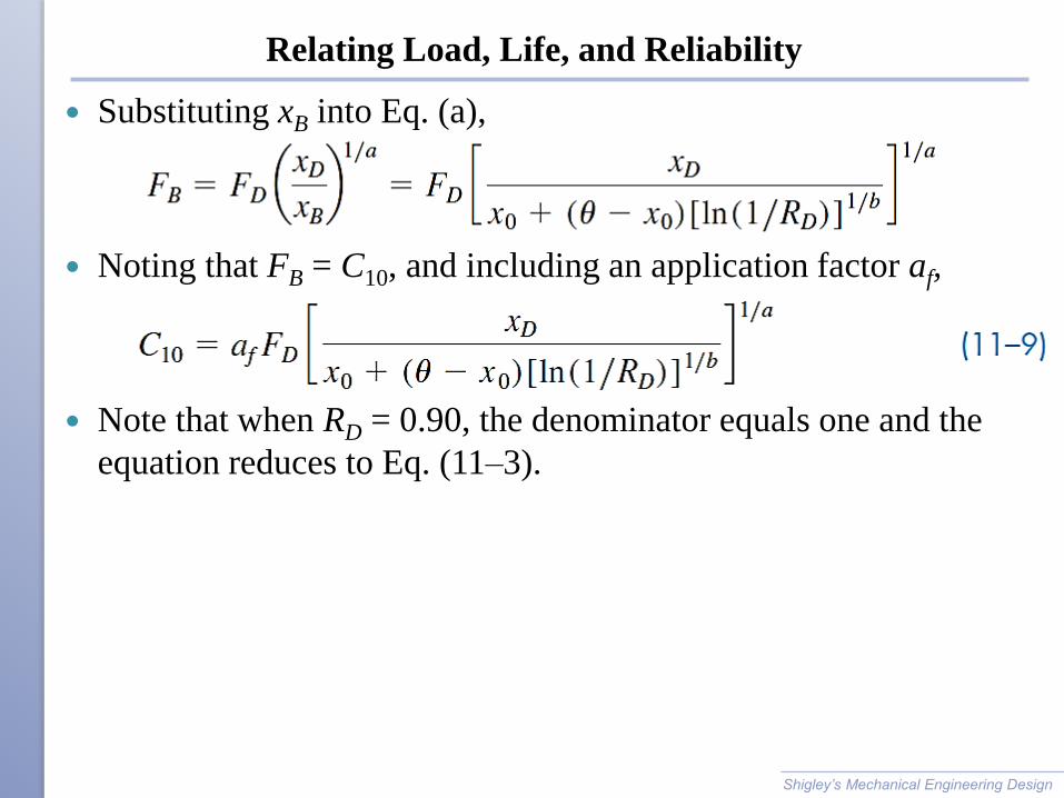
Relating Load, Life, and Reliability
Substituting xB into Eq. (a),
Noting that FB = C10, and including an application factor af,
Note that when RD = 0.90, the denominator equals one and the
equation reduces to Eq. (11–3).
Shigley’s Mechanical Engineering Design
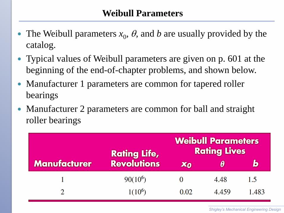
Weibull Parameters
The Weibull parameters x0, q, and b are usually provided by the
catalog.
Typical values of Weibull parameters are given on p. 601 at the
beginning of the end-of-chapter problems, and shown below.
Manufacturer 1 parameters are common for tapered roller
bearings
Manufacturer 2 parameters are common for ball and straight
roller bearings
Shigley’s Mechanical Engineering Design
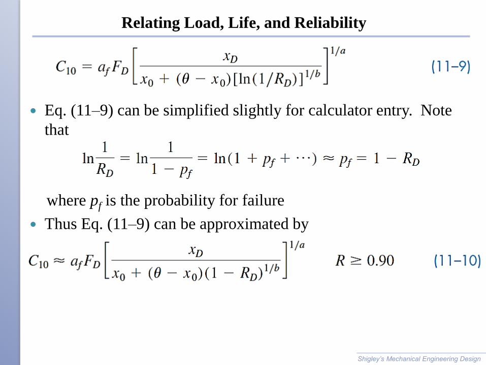
Relating Load, Life, and Reliability
Eq. (11–9) can be simplified slightly for calculator entry. Note
that
where pf is the probability for failure
Thus Eq. (11–9) can be approximated by
Shigley’s Mechanical Engineering Design
Example 11-3
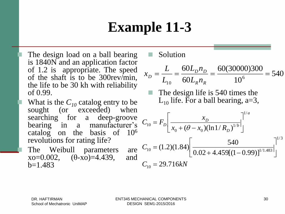
The design load on a ball bearing is 1840N and an application factor of 1.2 is appropriate. The speed of the shaft is to be 300rev/min, the life to be 30 kh with reliability of 0.99.
What is the C10 catalog entry to be sought (or exceeded) when searching for a deep-groove bearing in a manufacturer’s catalog on the basis of 106 revolutions for rating life?
The Weibull parameters are xo=0.002, (θ-xo)=4.439, and b=1.483
Solution
The design life is 540 times the L10 life. For a ball bearing, a=3,
54010
300)30000(60
60
606
10
RR
DDD
nL
nL
L
Lx
kNC
C
Rxx
xFC
a
b
D
DD
716.29
)]99.01[(459.402.0
540)84.1)(2.1(
)/1)(ln(
10
3/1
483.1/110
/1
/1
00
10
q
DR. HAFTIRMAN
School of Mechatronic UniMAP
30 ENT345 MECHANICAL COMPONENTS
DESIGN SEM1-2015/2016
Example
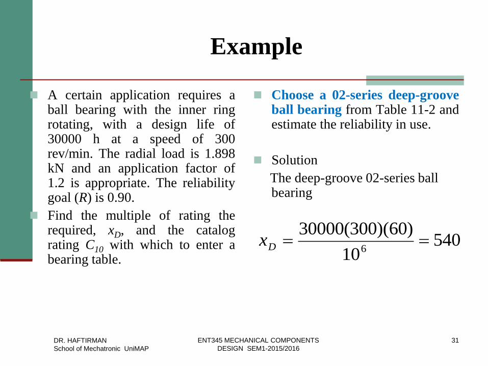
A certain application requires a ball bearing with the inner ring rotating, with a design life of 30000 h at a speed of 300 rev/min. The radial load is 1.898 kN and an application factor of 1.2 is appropriate. The reliability goal (R) is 0.90.
Find the multiple of rating the required, xD, and the catalog rating C10 with which to enter a bearing table.
Choose a 02-series deep-groove ball bearing from Table 11-2 and estimate the reliability in use.
Solution
The deep-groove 02-series ball bearing
54010
)60)(300(300006
Dx
DR. HAFTIRMAN
School of Mechatronic UniMAP
31 ENT345 MECHANICAL COMPONENTS
DESIGN SEM1-2015/2016
Example
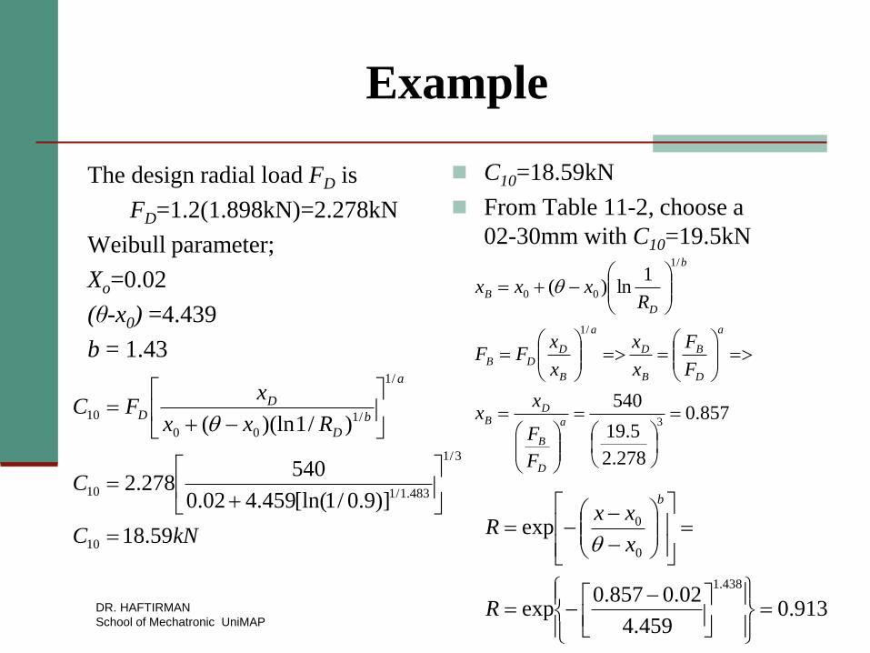
The design radial load FD is
FD=1.2(1.898kN)=2.278kN
Weibull parameter;
Xo=0.02
(θ-x0) =4.439
b = 1.43
C10=18.59kN
From Table 11-2, choose a
02-30mm with C10=19.5kN
kNC
C
Rxx
xFC
a
b
D
DD
59.18
)]9.0/1[ln(459.402.0
540278.2
)/1)(ln(
10
3/1
483.1/110
/1
/1
00
10
q857.0
278.2
5.19
540
1ln)(
3
/1
/1
00
a
D
B
DB
a
D
B
B
D
a
B
DDB
b
D
B
F
F
xx
F
F
x
x
x
xFF
Rxxx q
913.0459.4
02.0857.0exp
exp
438.1
0
0
R
x
xxR
b
q
DR. HAFTIRMAN
School of Mechatronic UniMAP
Example
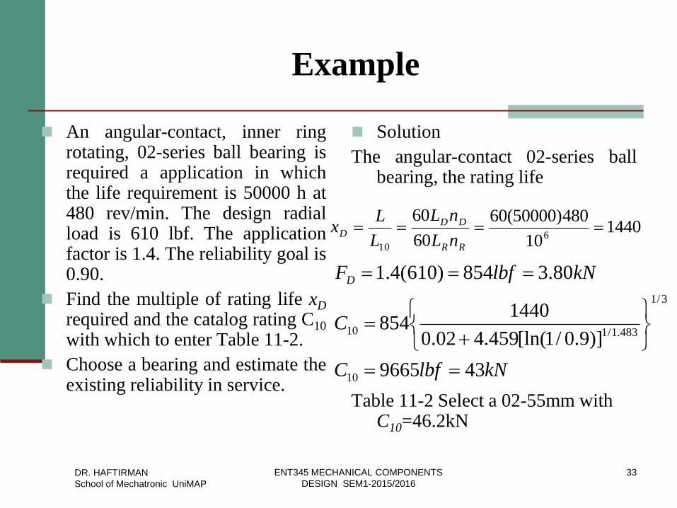
An angular-contact, inner ring rotating, 02-series ball bearing is required a application in which the life requirement is 50000 h at 480 rev/min. The design radial load is 610 lbf. The application factor is 1.4. The reliability goal is 0.90.
Find the multiple of rating life xD required and the catalog rating C10 with which to enter Table 11-2.
Choose a bearing and estimate the existing reliability in service.
Solution
The angular-contact 02-series ball bearing, the rating life
Table 11-2 Select a 02-55mm with C10=46.2kN
144010
480)50000(60
60
606
10
RR
DDD
nL
nL
L
Lx
kNlbfC
C
kNlbfFD
439665
)]9.0/1[ln(459.402.0
1440854
80.3854)610(4.1
10
3/1
483.1/110
DR. HAFTIRMAN
School of Mechatronic UniMAP
33 ENT345 MECHANICAL COMPONENTS
DESIGN SEM1-2015/2016
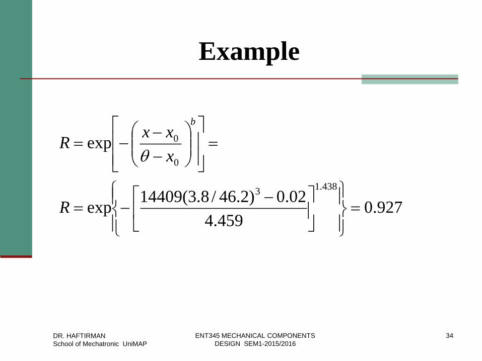
Example
927.0459.4
02.0)2.46/8.3(14409exp
exp
438.13
0
0
R
x
xxR
b
q
DR. HAFTIRMAN
School of Mechatronic UniMAP
34 ENT345 MECHANICAL COMPONENTS
DESIGN SEM1-2015/2016
Combined Reliability of Multiple Bearings
If the combined reliability of multiple bearings on a shaft, or in a
gearbox, is desired, then the total reliability is equal to the
product of the individual reliabilities.
For two bearings on a shaft, R = RARB
If the bearings are to be identical, each bearing should have a
reliability equal to the square root of the total desired reliability.
If the bearings are not identical, their reliabilities need not be
identical, so long as the total reliability is realized.
Shigley’s Mechanical Engineering Design
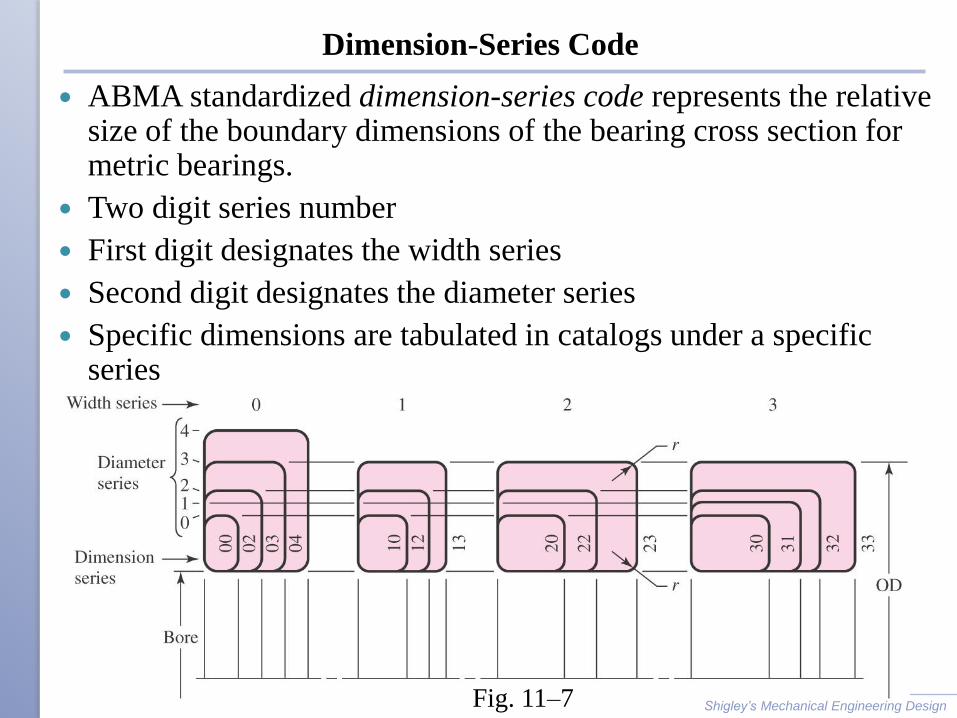
Dimension-Series Code
ABMA standardized dimension-series code represents the relative size of the boundary dimensions of the bearing cross section for metric bearings.
Two digit series number
First digit designates the width series
Second digit designates the diameter series
Specific dimensions are tabulated in catalogs under a specific series
Shigley’s Mechanical Engineering Design Fig. 11–7
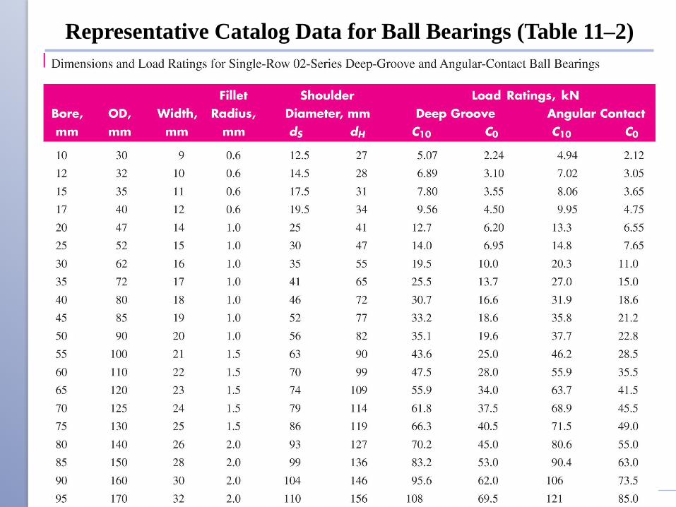
Representative Catalog Data for Ball Bearings (Table 11–2)
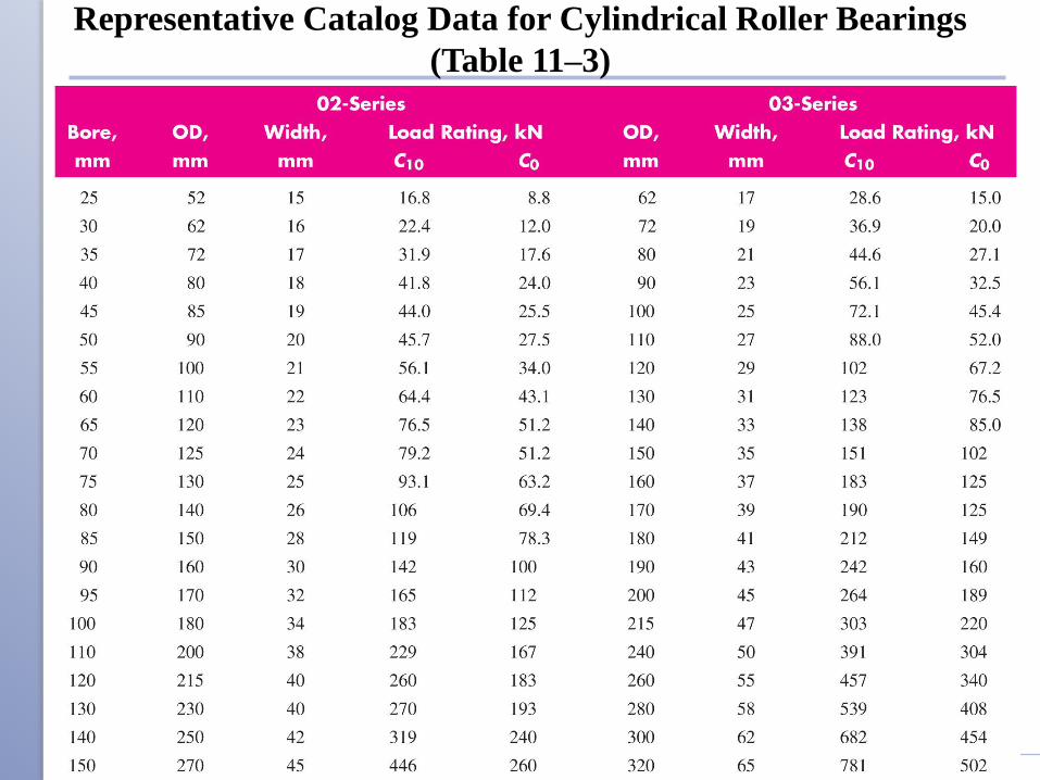
Representative Catalog Data for Cylindrical Roller Bearings
(Table 11–3)
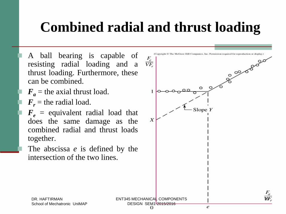
Combined radial and thrust loading
A ball bearing is capable of resisting radial loading and a thrust loading. Furthermore, these can be combined.
Fa = the axial thrust load.
Fr = the radial load.
Fe = equivalent radial load that does the same damage as the combined radial and thrust loads together.
The abscissa e is defined by the intersection of the two lines.
DR. HAFTIRMAN
School of Mechatronic UniMAP
39 ENT345 MECHANICAL COMPONENTS
DESIGN SEM1-2015/2016
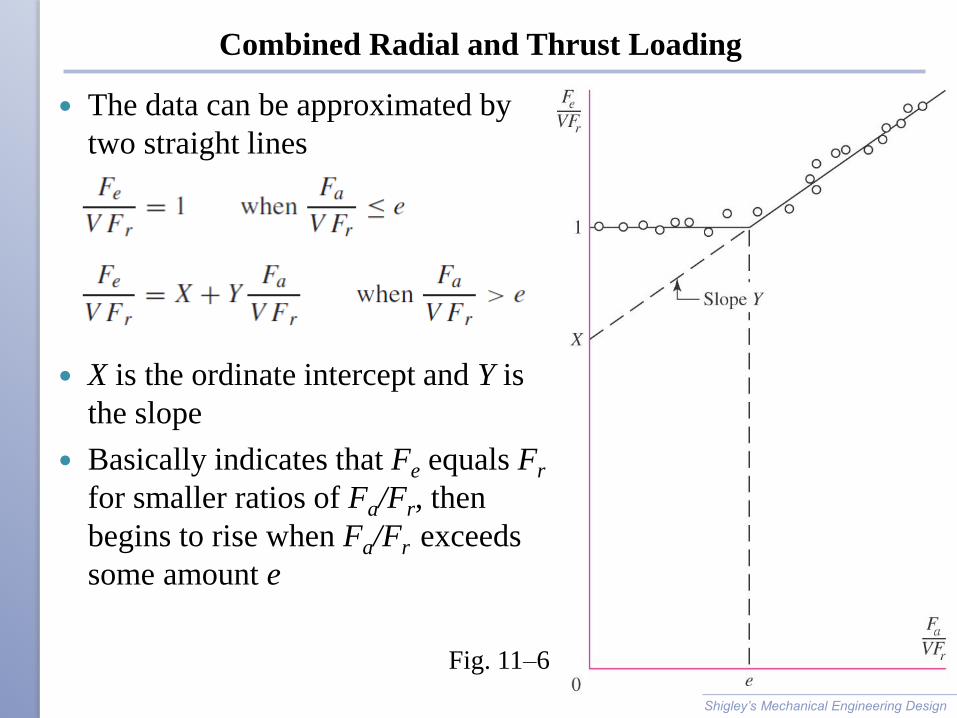
Combined Radial and Thrust Loading
The data can be approximated by
two straight lines
X is the ordinate intercept and Y is
the slope
Basically indicates that Fe equals Fr
for smaller ratios of Fa/Fr, then
begins to rise when Fa/Fr exceeds
some amount e
Shigley’s Mechanical Engineering Design
Fig. 11–6

Combined Radial and Thrust Loading
It is common to express the two
equations as a single equation
where
i = 1 when Fa /(VFr) ≤ e
i = 2 when Fa /(VFr) > e
X and Y factors depend on geometry
and construction of the specific
bearing.
Shigley’s Mechanical Engineering Design
Fig. 11–6
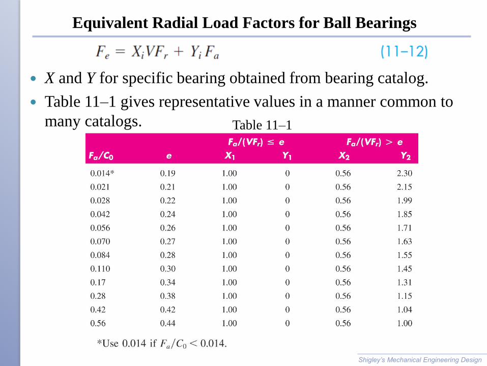
Equivalent Radial Load Factors for Ball Bearings
X and Y for specific bearing obtained from bearing catalog.
Table 11–1 gives representative values in a manner common to
many catalogs.
Shigley’s Mechanical Engineering Design
Table 11–1
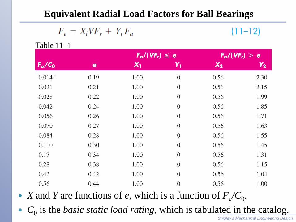
Equivalent Radial Load Factors for Ball Bearings
X and Y are functions of e, which is a function of Fa/C0.
C0 is the basic static load rating, which is tabulated in the catalog.
Shigley’s Mechanical Engineering Design
Table 11–1
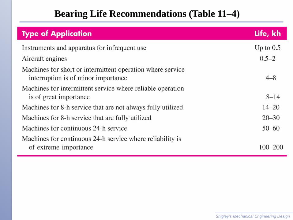
Bearing Life Recommendations (Table 11–4)
Shigley’s Mechanical Engineering Design
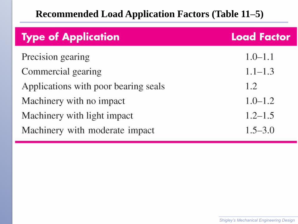
Recommended Load Application Factors (Table 11–5)
Shigley’s Mechanical Engineering Design
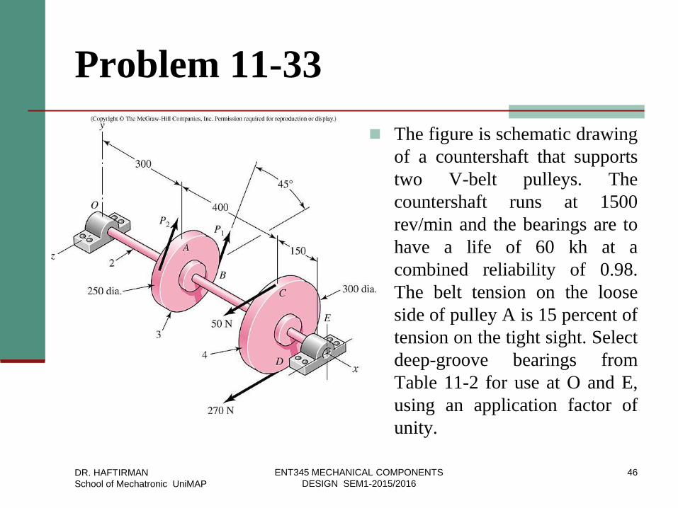
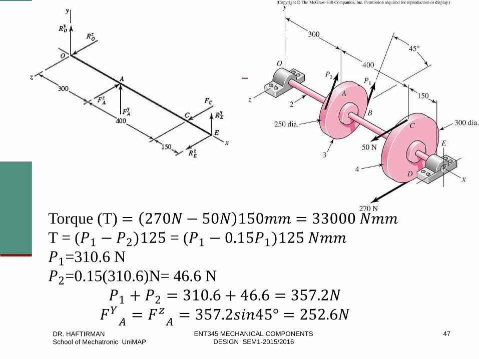
Problem 11-33
The figure is schematic drawing
of a countershaft that supports
two V-belt pulleys. The
countershaft runs at 1500
rev/min and the bearings are to
have a life of 60 kh at a
combined reliability of 0.98.
The belt tension on the loose
side of pulley A is 15 percent of
tension on the tight sight. Select
deep-groove bearings from
Table 11-2 for use at O and E,
using an application factor of
unity.
DR. HAFTIRMAN
School of Mechatronic UniMAP
ENT345 MECHANICAL COMPONENTS
DESIGN SEM1-2015/2016
46
DR. HAFTIRMAN
School of Mechatronic UniMAP
ENT345 MECHANICAL COMPONENTS
DESIGN SEM1-2015/2016
47
Torque (T) = 270𝑁 − 50𝑁 150𝑚𝑚 = 33000 𝑁𝑚𝑚
T = (𝑃1 − 𝑃2)125 = (𝑃1 − 0.15𝑃1)125 𝑁𝑚𝑚
𝑃1=310.6 N
𝑃2=0.15(310.6)N= 46.6 N
𝑃1 + 𝑃2 = 310.6 + 46.6 = 357.2𝑁
𝐹𝑌𝐴 = 𝐹𝑧𝐴 = 357.2𝑠𝑖𝑛45° = 252.6𝑁
DR. HAFTIRMAN
School of Mechatronic UniMAP
ENT345 MECHANICAL COMPONENTS
DESIGN SEM1-2015/2016
48
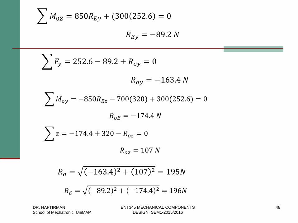
𝑀0𝑍 = 850𝑅𝐸𝑦 + (300 252.6 = 0
𝑅𝐸𝑦 = −89.2 𝑁
𝐹𝑦 = 252.6 − 89.2 + 𝑅𝑜𝑦 = 0
𝑅𝑜𝑦 = −163.4 𝑁
𝑀𝑜𝑦 = −850𝑅𝐸𝑧 − 700(320) + 300(252.6) = 0
𝑅𝑜𝐸 = −174.4 𝑁
𝑧 = −174.4 + 320 − 𝑅𝑜𝑧 = 0
𝑅𝑜𝑧 = 107 𝑁
𝑅𝑜 = −163.4 2 + 107 2 = 195𝑁
𝑅𝐸 = −89.2 2 + −174.4 2 = 196𝑁
DR. HAFTIRMAN
School of Mechatronic UniMAP
ENT345 MECHANICAL COMPONENTS
DESIGN SEM1-2015/2016
49
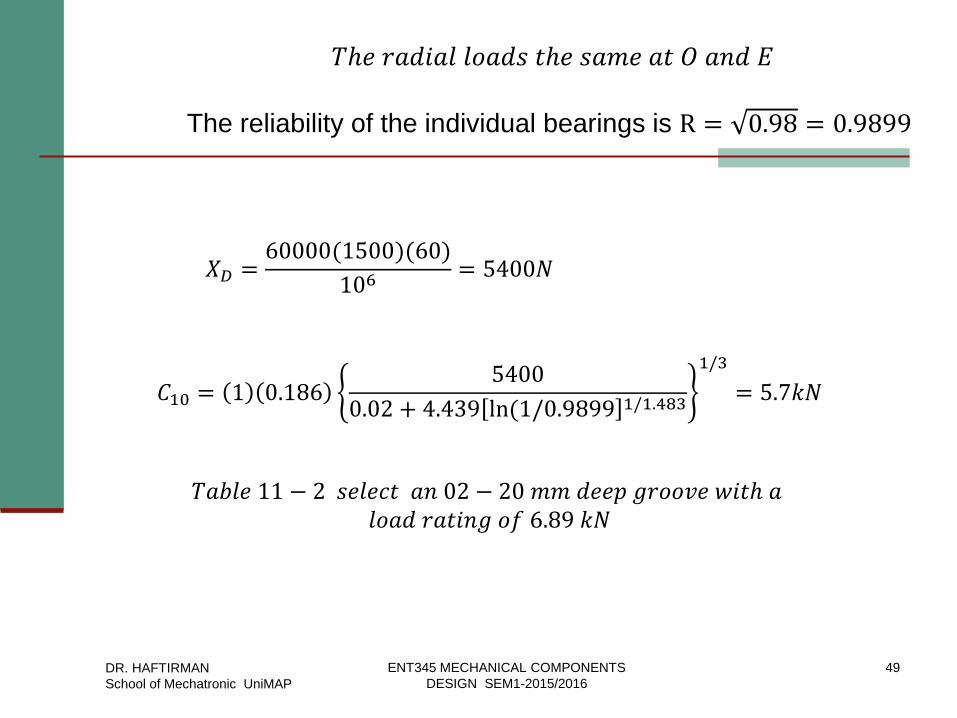
𝑇ℎ𝑒 𝑟𝑎𝑑𝑖𝑎𝑙 𝑙𝑜𝑎𝑑𝑠 𝑡ℎ𝑒 𝑠𝑎𝑚𝑒 𝑎𝑡 𝑂 𝑎𝑛𝑑 𝐸
The reliability of the individual bearings is R = 0.98 = 0.9899
𝑋𝐷 =60000(1500)(60)
106= 5400𝑁
𝐶10 = 1 0.1865400
0.02 + 4.439 ln (1/0.9899 1/1.483
1/3
= 5.7𝑘𝑁
𝑇𝑎𝑏𝑙𝑒 11 − 2 𝑠𝑒𝑙𝑒𝑐𝑡 𝑎𝑛 02 − 20 𝑚𝑚 𝑑𝑒𝑒𝑝 𝑔𝑟𝑜𝑜𝑣𝑒 𝑤𝑖𝑡ℎ 𝑎 𝑙𝑜𝑎𝑑 𝑟𝑎𝑡𝑖𝑛𝑔 𝑜𝑓 6.89 𝑘𝑁
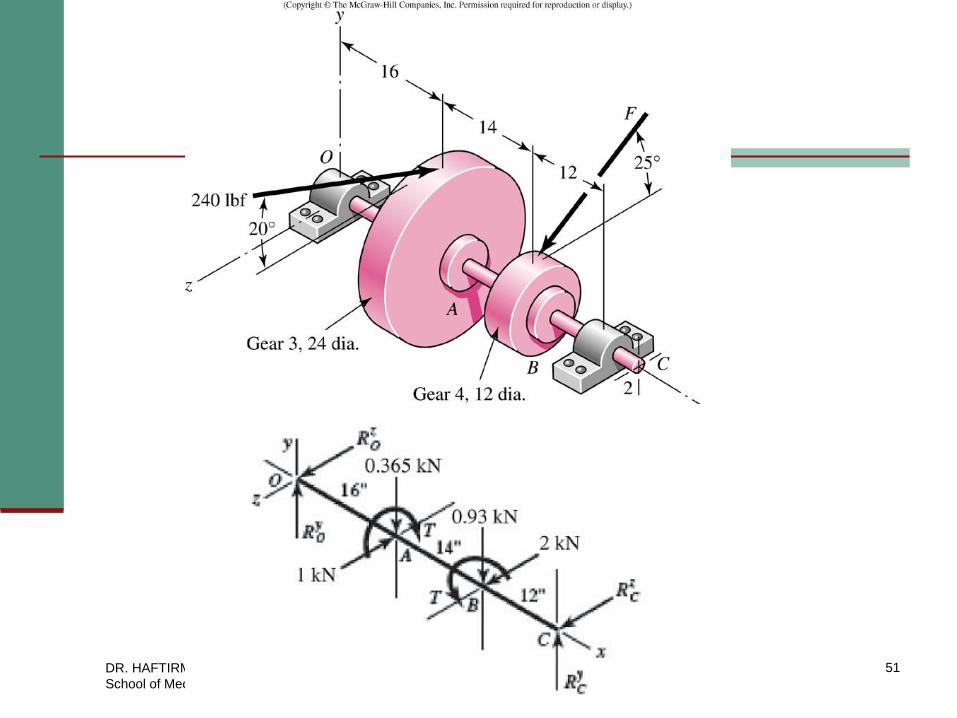
Problem 11-34
A gear reduction unit uses the countershaft depicted
in the figure. Find the two bearing reactions. The
bearings are to be angular-contact ball bearings,
having a desired life of 40 kh when used at 200
rev/min. Use 1.2 for application factor and reliability
goal for the bearing pair of 0.95. Select the bearings
from Table 11-2.
DR. HAFTIRMAN
School of Mechatronic UniMAP
ENT345 MECHANICAL COMPONENTS
DESIGN SEM1-2015/2016
50
DR. HAFTIRMAN
School of Mechatronic UniMAP
ENT345 MECHANICAL COMPONENTS
DESIGN SEM1-2015/2016
51
DR. HAFTIRMAN
School of Mechatronic UniMAP
ENT345 MECHANICAL COMPONENTS
DESIGN SEM1-2015/2016
52
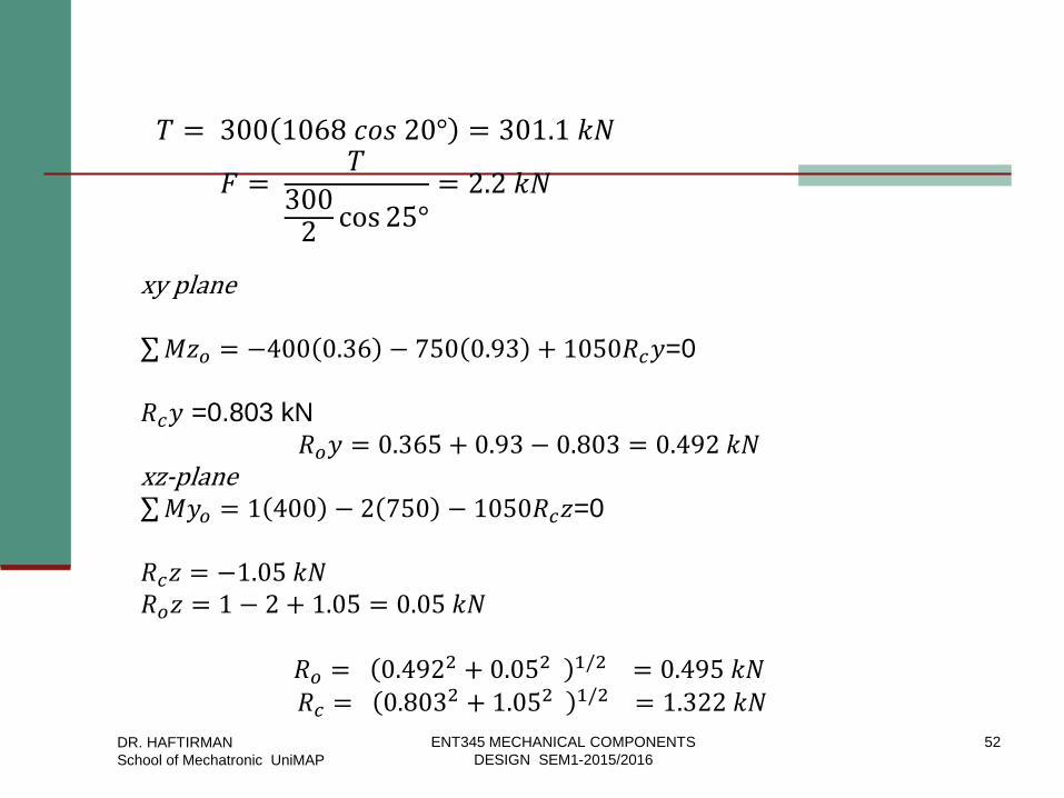
𝑇 = 300 1068 𝑐𝑜𝑠 20° = 301.1 𝑘𝑁
𝐹 = 𝑇
3002cos 25°
= 2.2 𝑘𝑁
xy plane 𝑀𝑧𝑜 = −400 0.36 − 750 0.93 + 1050𝑅𝑐𝑦=0
𝑅𝑐𝑦 =0.803 kN
𝑅𝑜𝑦 = 0.365 + 0.93 − 0.803 = 0.492 𝑘𝑁 xz-plane 𝑀𝑦𝑜 = 1 400 − 2 750 − 1050𝑅𝑐𝑧=0
𝑅𝑐𝑧 = −1.05 𝑘𝑁
𝑅𝑜𝑧 = 1 − 2 + 1.05 = 0.05 𝑘𝑁
𝑅𝑜 = 0.492
2 + 0.052 1/2 = 0.495 𝑘𝑁 𝑅𝑐 = 0.803
2 + 1.052 1/2 = 1.322 𝑘𝑁
DR. HAFTIRMAN
School of Mechatronic UniMAP
ENT345 MECHANICAL COMPONENTS
DESIGN SEM1-2015/2016
53
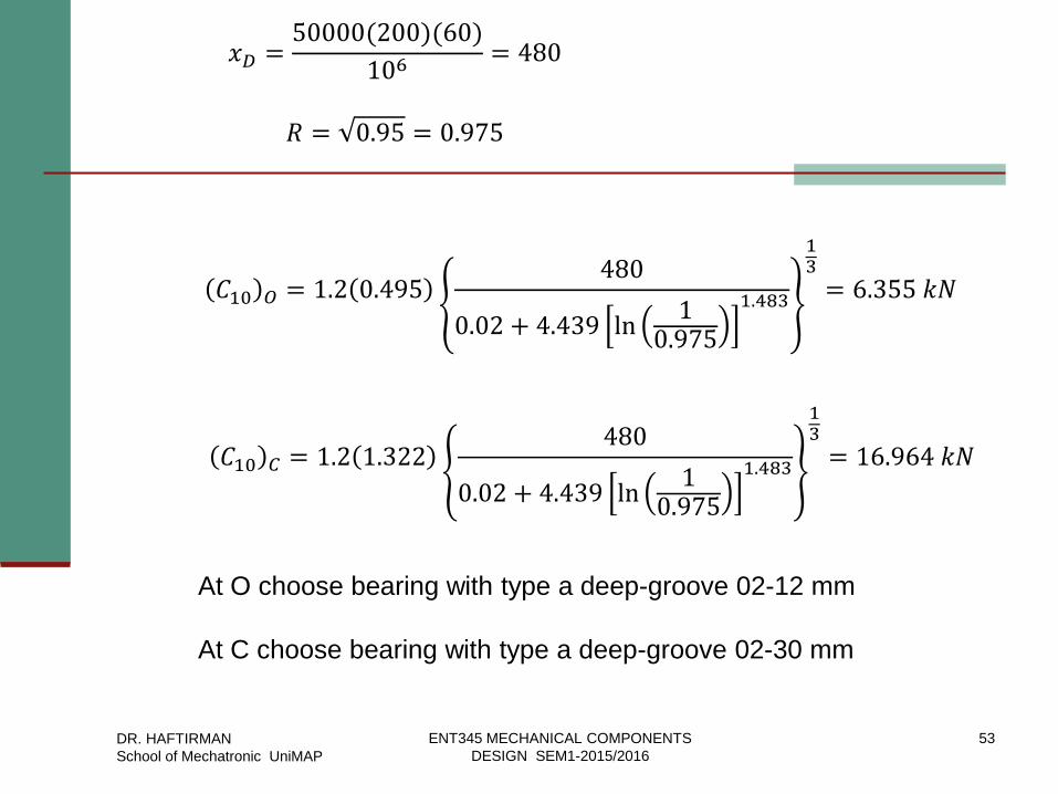
𝑥𝐷 =50000(200)(60)
106= 480
𝑅 = 0.95 = 0.975
𝐶10 𝑂 = 1.2 0.495480
0.02 + 4.439 ln10.975
1.483
13
= 6.355 𝑘𝑁
𝐶10 𝐶 = 1.2 1.322480
0.02 + 4.439 ln10.975
1.483
13
= 16.964 𝑘𝑁
At O choose bearing with type a deep-groove 02-12 mm
At C choose bearing with type a deep-groove 02-30 mm
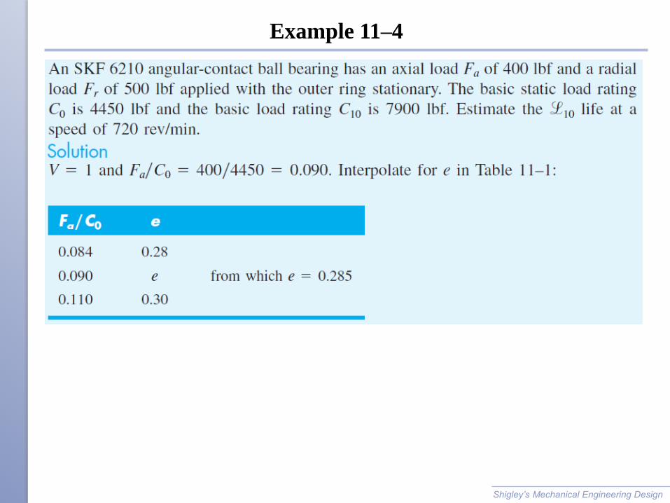
Example 11–4
Shigley’s Mechanical Engineering Design
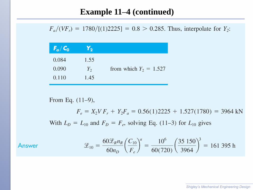
Example 11–4 (continued)
Shigley’s Mechanical Engineering Design
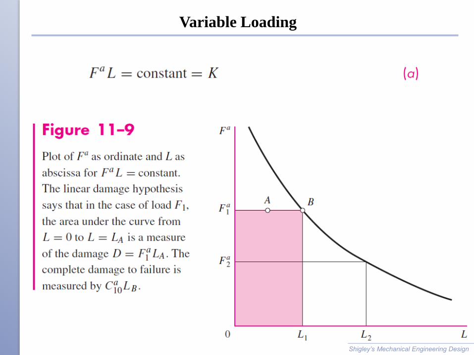
Variable Loading
Shigley’s Mechanical Engineering Design
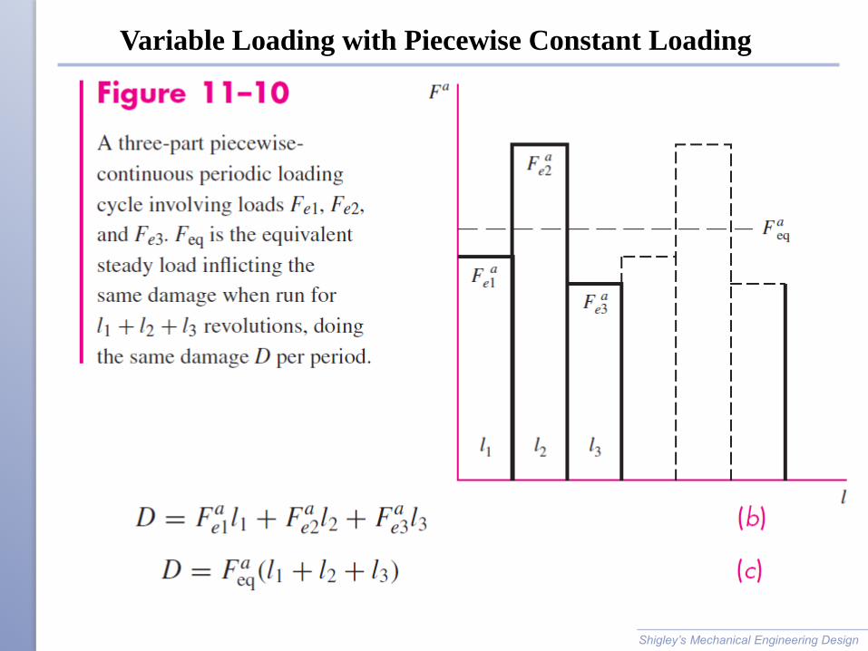
Variable Loading with Piecewise Constant Loading
Shigley’s Mechanical Engineering Design
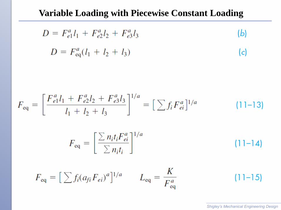
Variable Loading with Piecewise Constant Loading
Shigley’s Mechanical Engineering Design
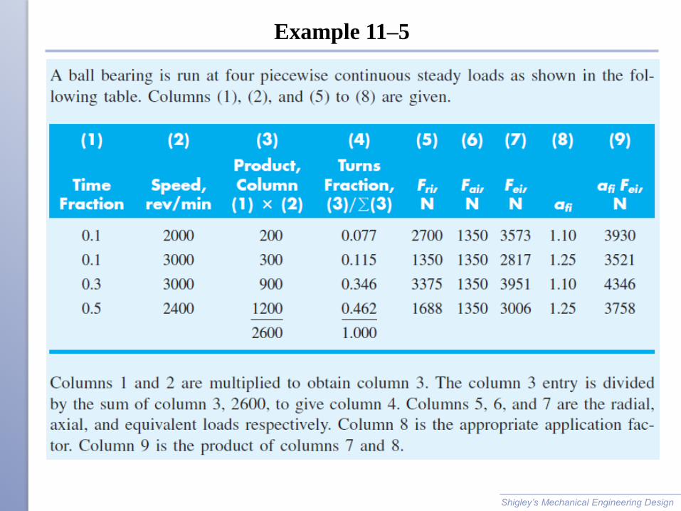
Example 11–5
Shigley’s Mechanical Engineering Design
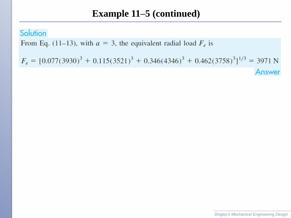
Example 11–5 (continued)
Shigley’s Mechanical Engineering Design
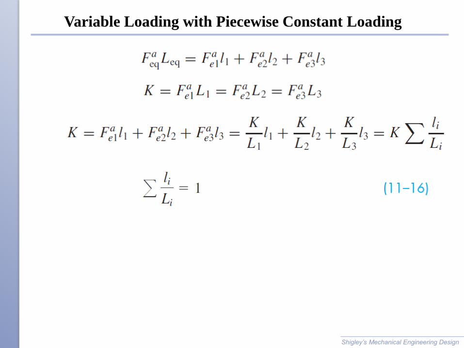
Variable Loading with Piecewise Constant Loading
Shigley’s Mechanical Engineering Design
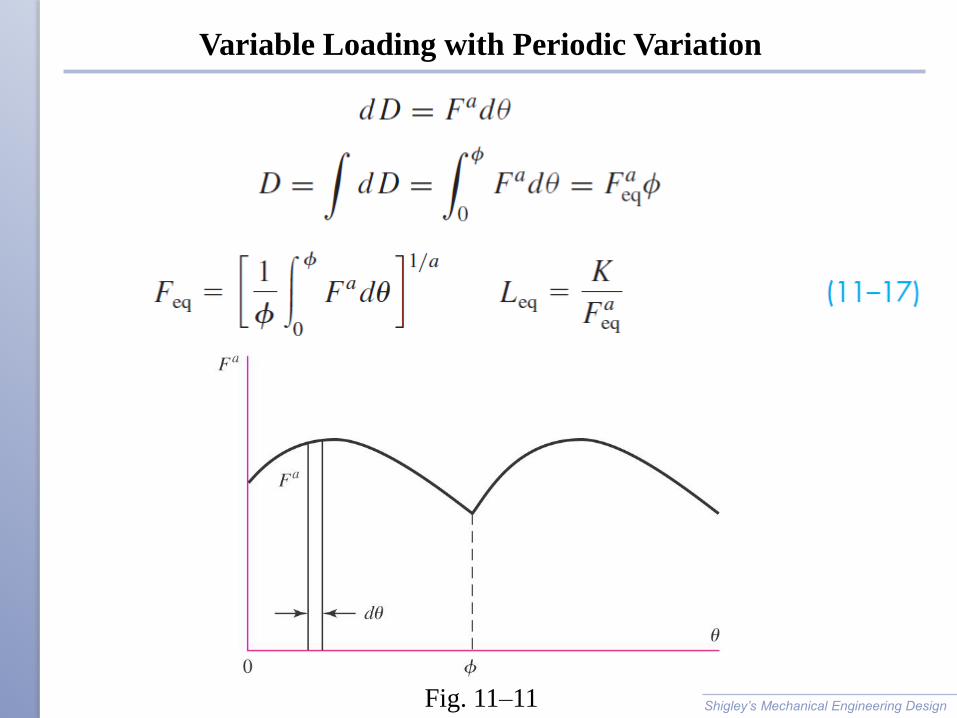
Variable Loading with Periodic Variation
Shigley’s Mechanical Engineering Design
Fig. 11–11
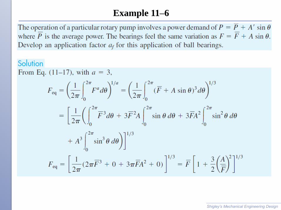
Example 11–6
Shigley’s Mechanical Engineering Design
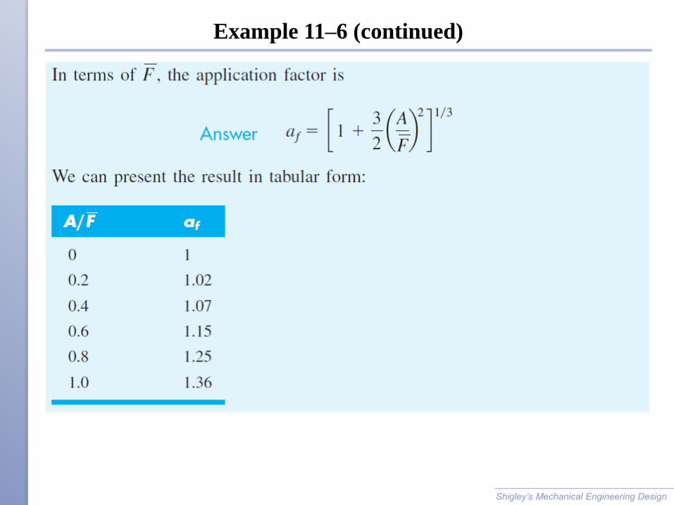
Example 11–6 (continued)
Shigley’s Mechanical Engineering Design
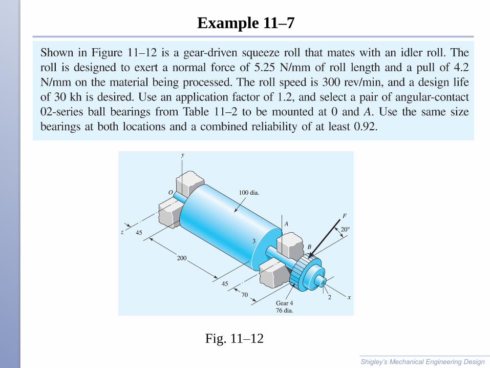
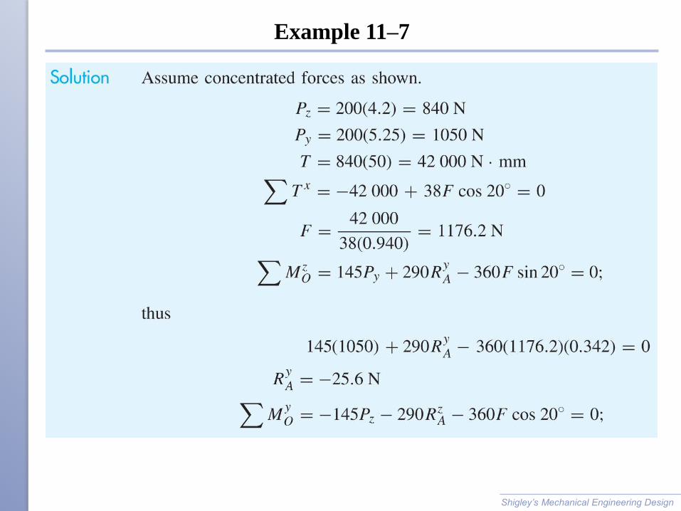
Example 11–7
Shigley’s Mechanical Engineering Design
Fig. 11–12
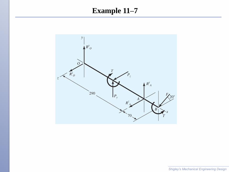
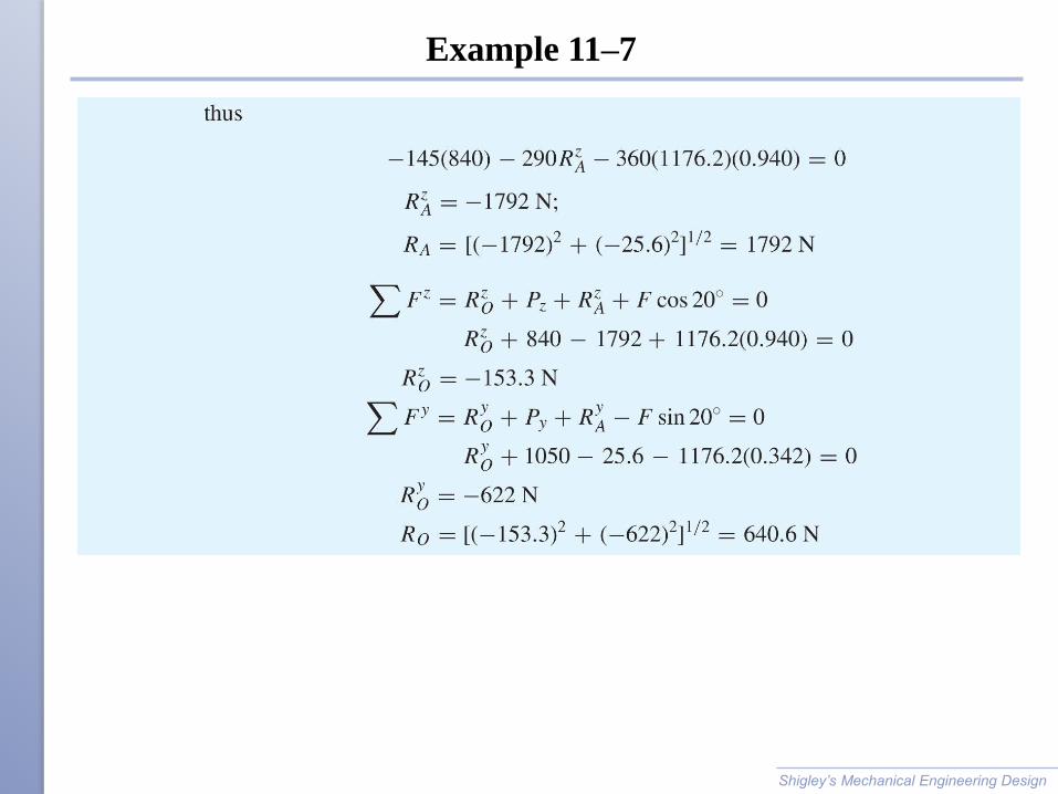
Example 11–7
Shigley’s Mechanical Engineering Design
Example 11–7
Shigley’s Mechanical Engineering Design
Example 11–7
Shigley’s Mechanical Engineering Design
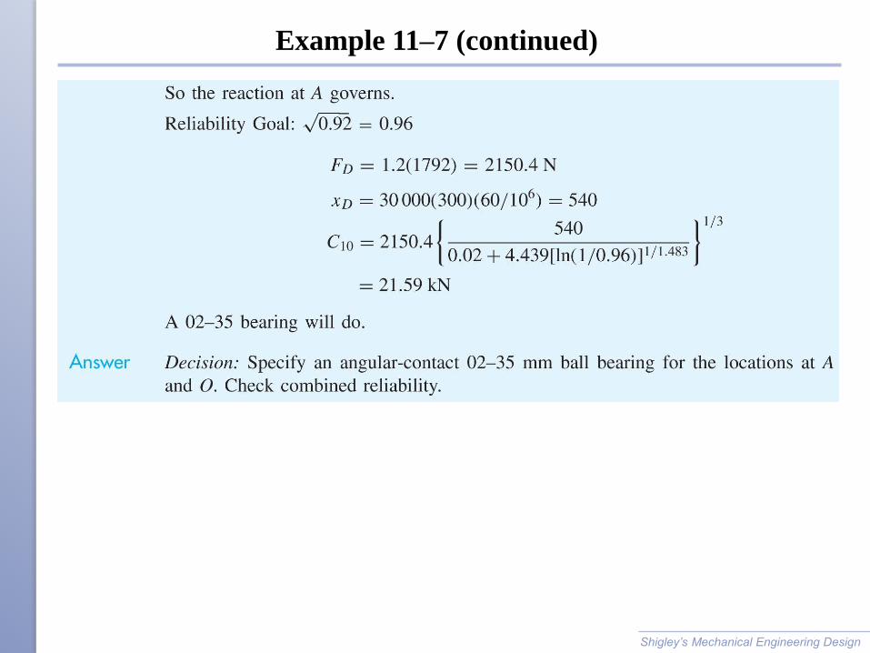
Example 11–7 (continued)
Shigley’s Mechanical Engineering Design
Tapered Roller Bearings
Straight roller bearings can carry large radial loads, but no axial
load.
Ball bearings can carry moderate radial loads, and small axial
loads.
Tapered roller bearings rely on roller tipped at an angle to allow
them to carry large radial and large axial loads.
Tapered roller bearings were popularized by the Timken Company.
Shigley’s Mechanical Engineering Design
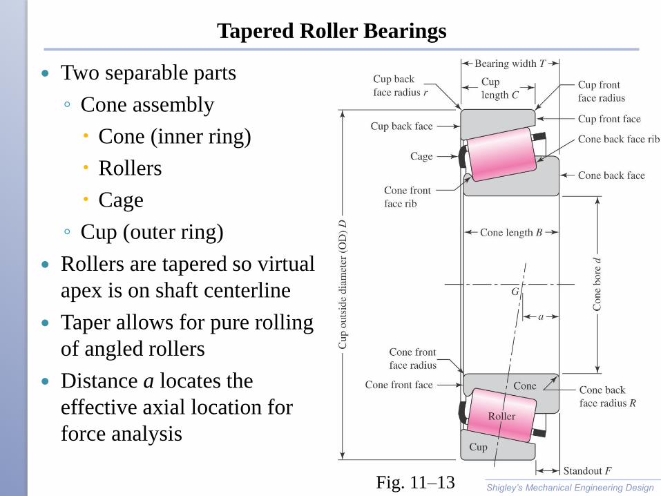
Tapered Roller Bearings
Two separable parts
◦ Cone assembly
Cone (inner ring)
Rollers
Cage
◦ Cup (outer ring)
Rollers are tapered so virtual
apex is on shaft centerline
Taper allows for pure rolling
of angled rollers
Distance a locates the
effective axial location for
force analysis
Shigley’s Mechanical Engineering Design Fig. 11–13
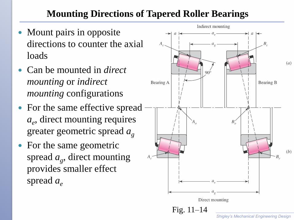
Mounting Directions of Tapered Roller Bearings
Mount pairs in opposite
directions to counter the axial
loads
Can be mounted in direct
mounting or indirect
mounting configurations
For the same effective spread
ae, direct mounting requires
greater geometric spread ag
For the same geometric
spread ag, direct mounting
provides smaller effect
spread ae
Shigley’s Mechanical Engineering Design
Fig. 11–14
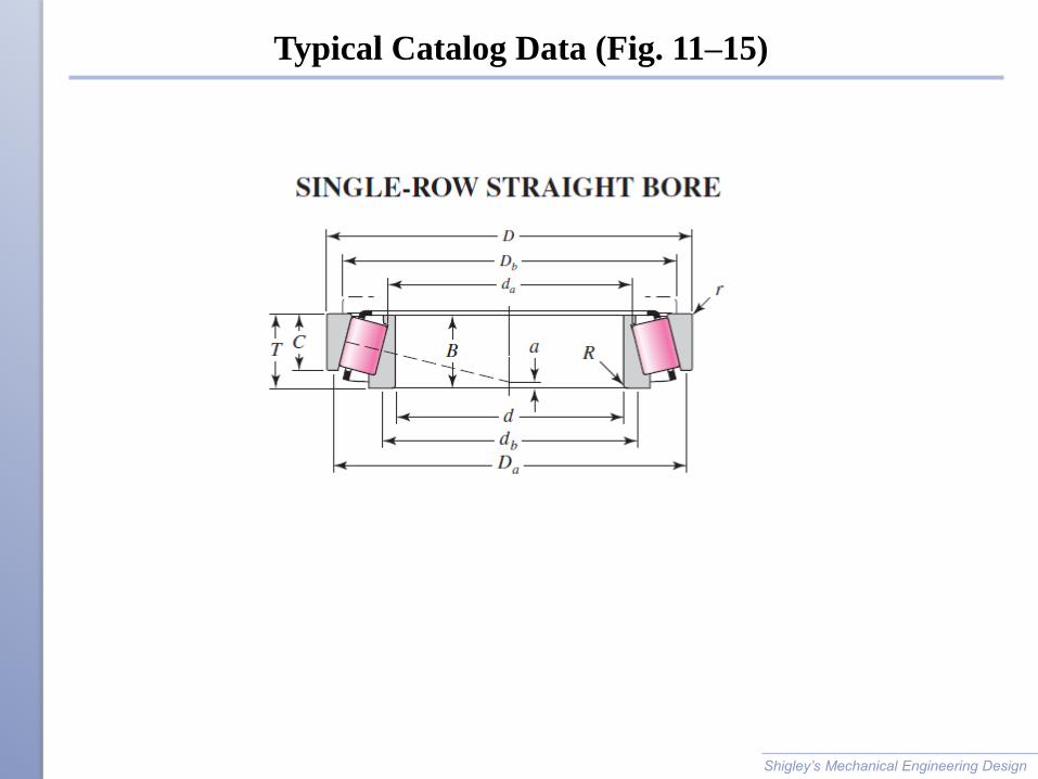
Typical Catalog Data (Fig. 11–15)
Shigley’s Mechanical Engineering Design
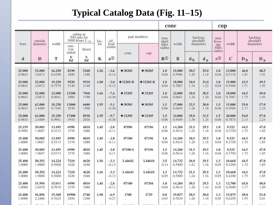
Typical Catalog Data (Fig. 11–15)
Shigley’s Mechanical Engineering Design
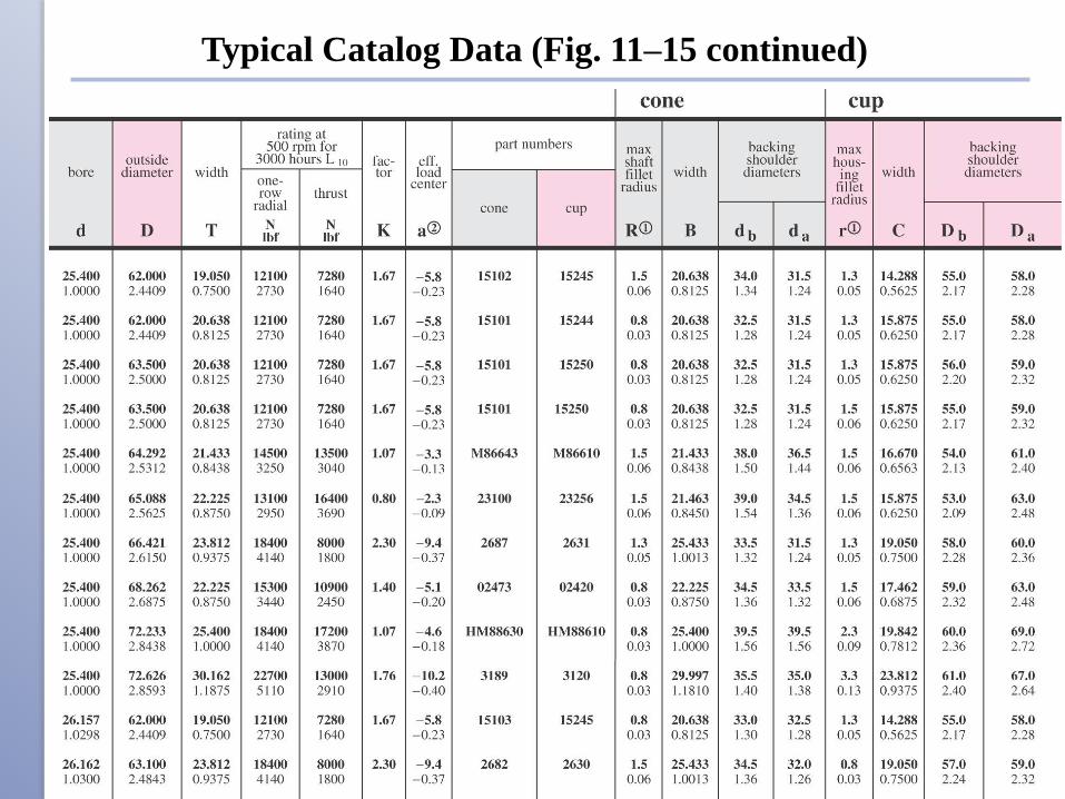
Typical Catalog Data (Fig. 11–15 continued)
Shigley’s Mechanical Engineering Design
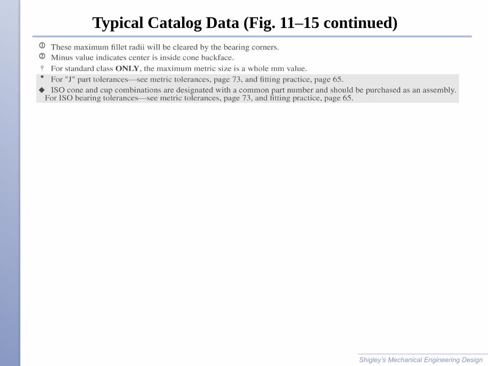
Typical Catalog Data (Fig. 11–15 continued)
Shigley’s Mechanical Engineering Design
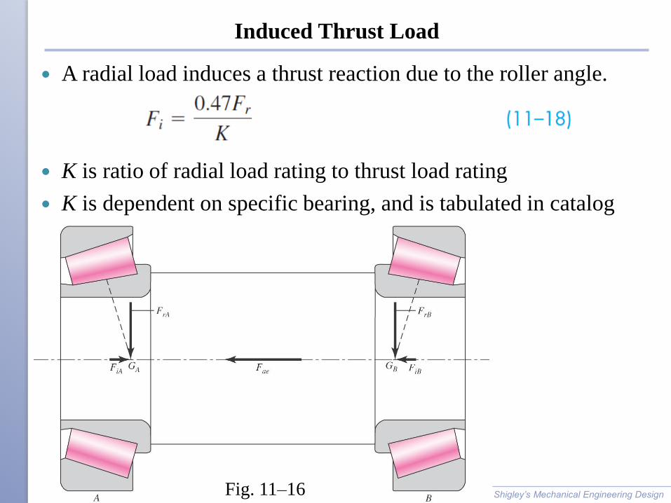
Induced Thrust Load
A radial load induces a thrust reaction due to the roller angle.
K is ratio of radial load rating to thrust load rating
K is dependent on specific bearing, and is tabulated in catalog
Shigley’s Mechanical Engineering Design Fig. 11–16
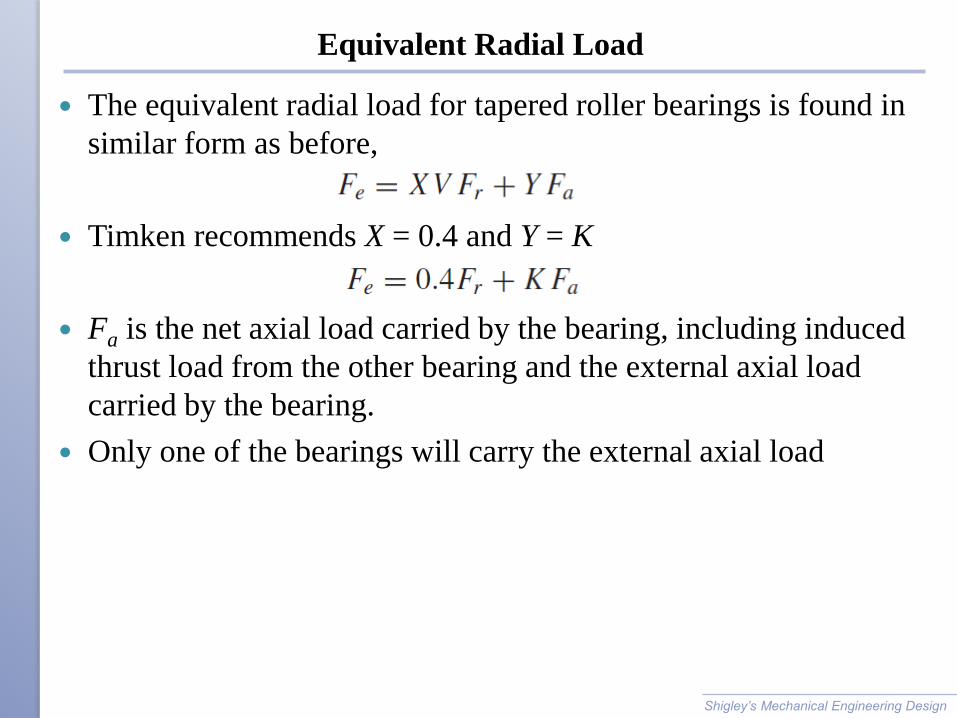
Equivalent Radial Load
The equivalent radial load for tapered roller bearings is found in
similar form as before,
Timken recommends X = 0.4 and Y = K
Fa is the net axial load carried by the bearing, including induced
thrust load from the other bearing and the external axial load
carried by the bearing.
Only one of the bearings will carry the external axial load
Shigley’s Mechanical Engineering Design
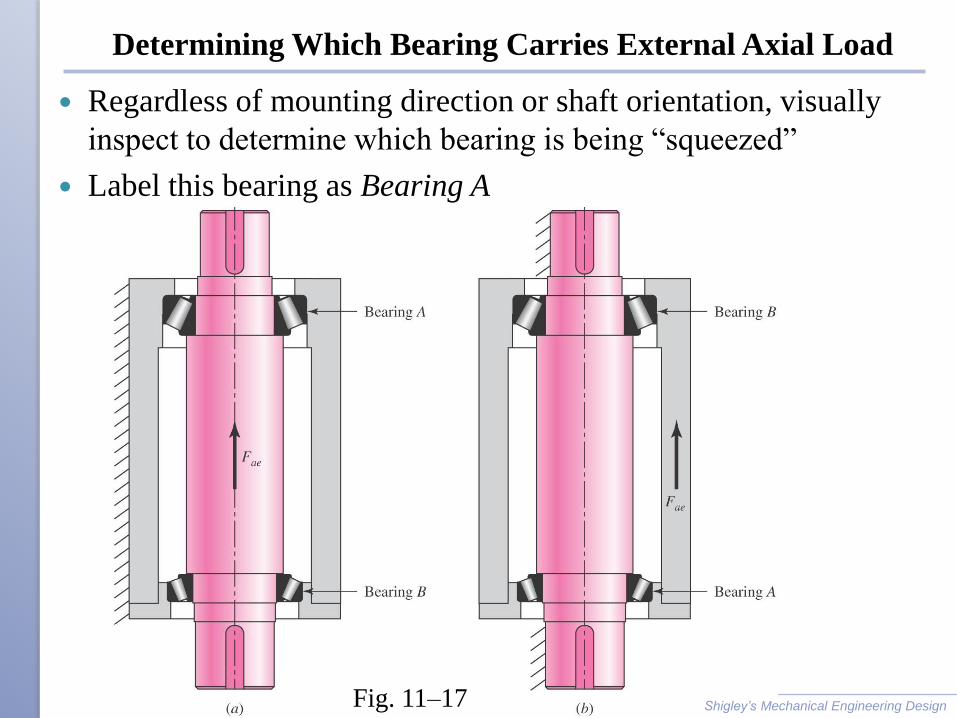
Determining Which Bearing Carries External Axial Load
Regardless of mounting direction or shaft orientation, visually
inspect to determine which bearing is being “squeezed”
Label this bearing as Bearing A
Shigley’s Mechanical Engineering Design Fig. 11–17
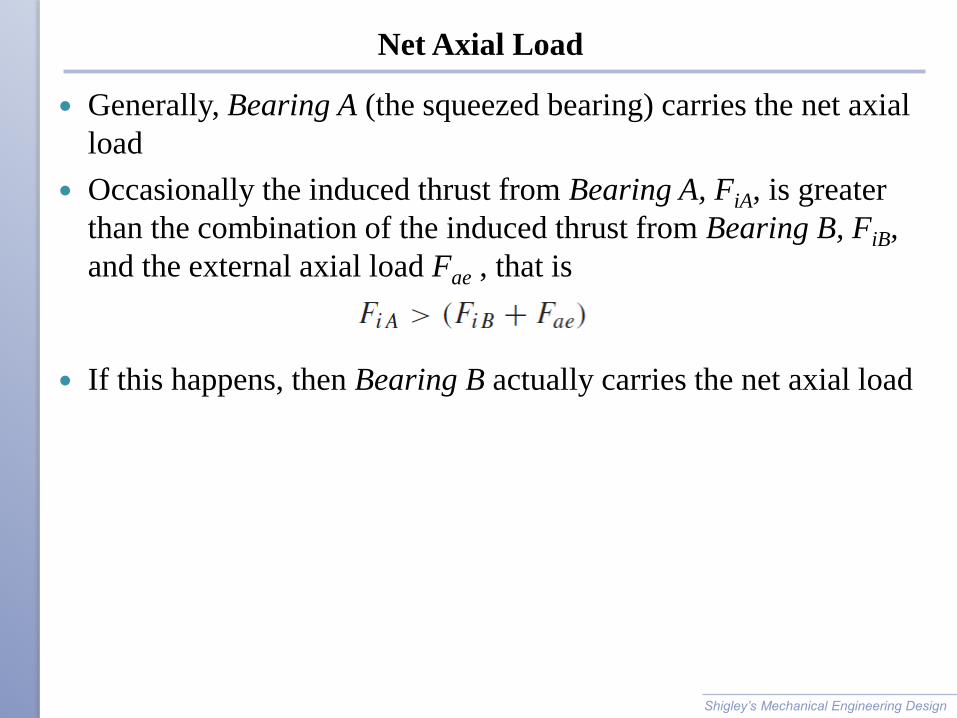
Net Axial Load
Generally, Bearing A (the squeezed bearing) carries the net axial
load
Occasionally the induced thrust from Bearing A, FiA, is greater
than the combination of the induced thrust from Bearing B, FiB,
and the external axial load Fae , that is
If this happens, then Bearing B actually carries the net axial load
Shigley’s Mechanical Engineering Design
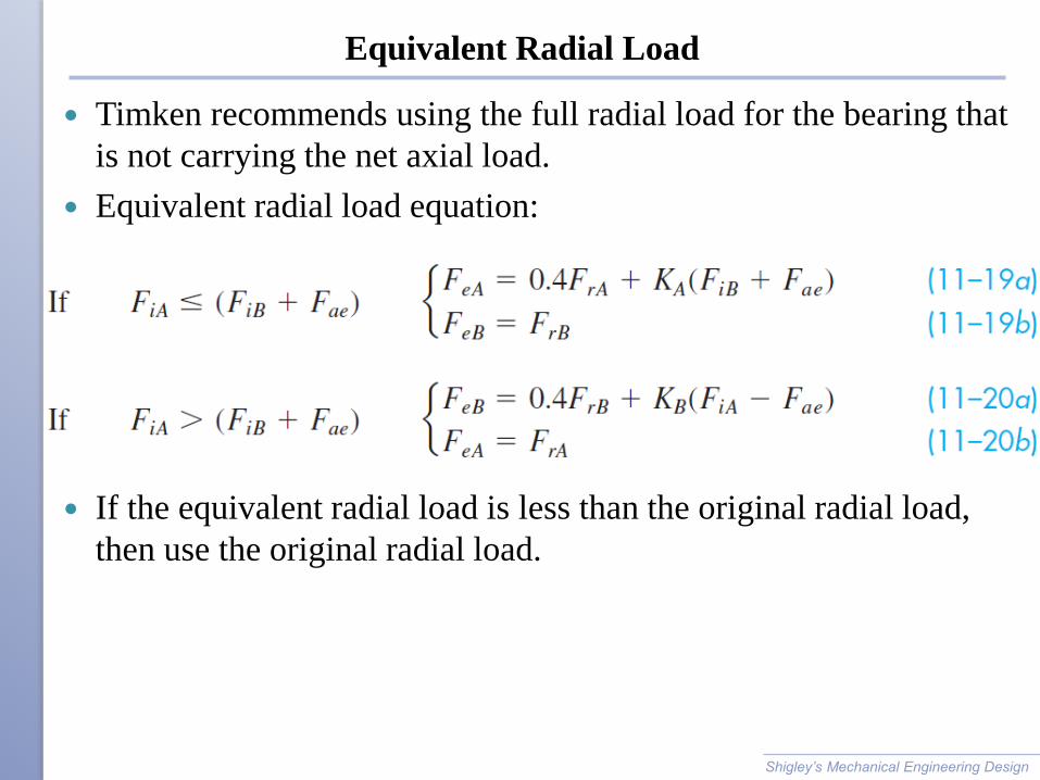
Equivalent Radial Load
Timken recommends using the full radial load for the bearing that
is not carrying the net axial load.
Equivalent radial load equation:
If the equivalent radial load is less than the original radial load,
then use the original radial load.
Shigley’s Mechanical Engineering Design
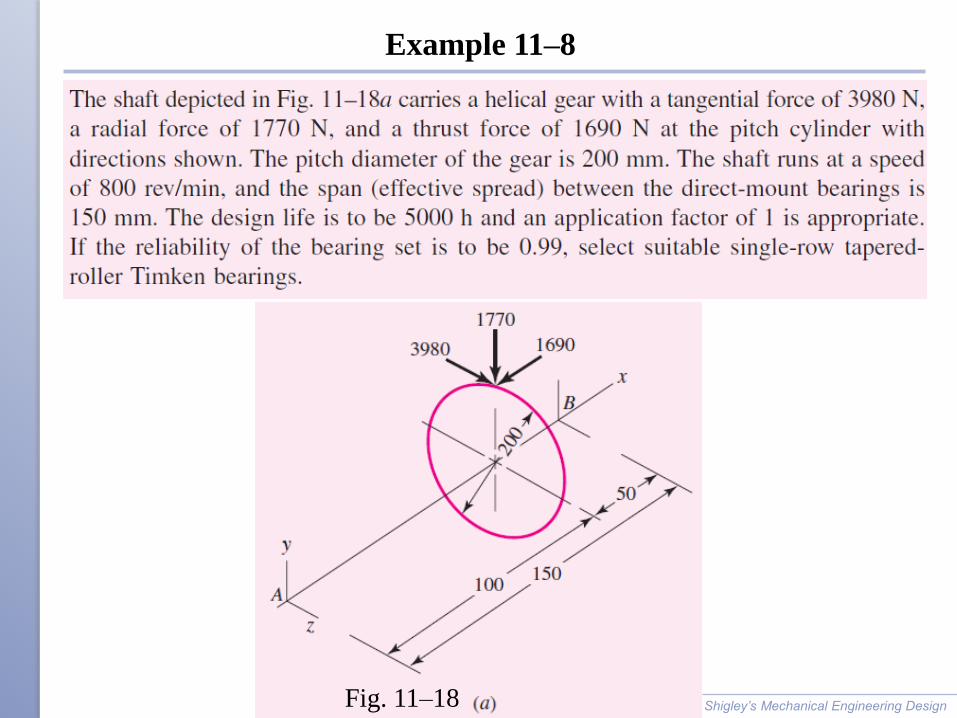
Example 11–8
Shigley’s Mechanical Engineering Design Fig. 11–18
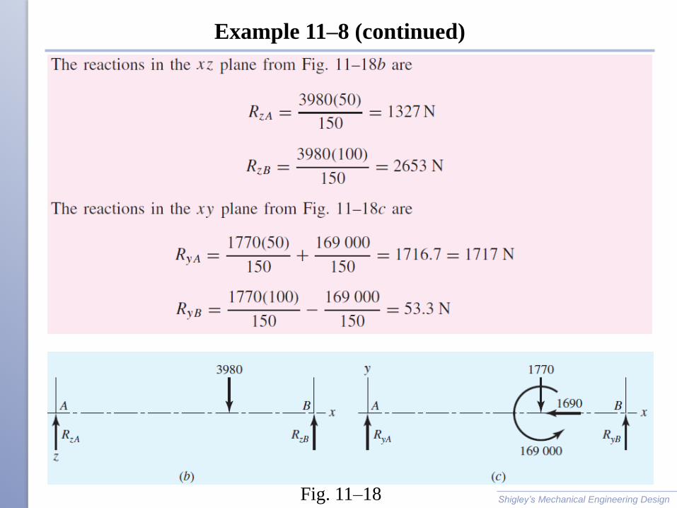
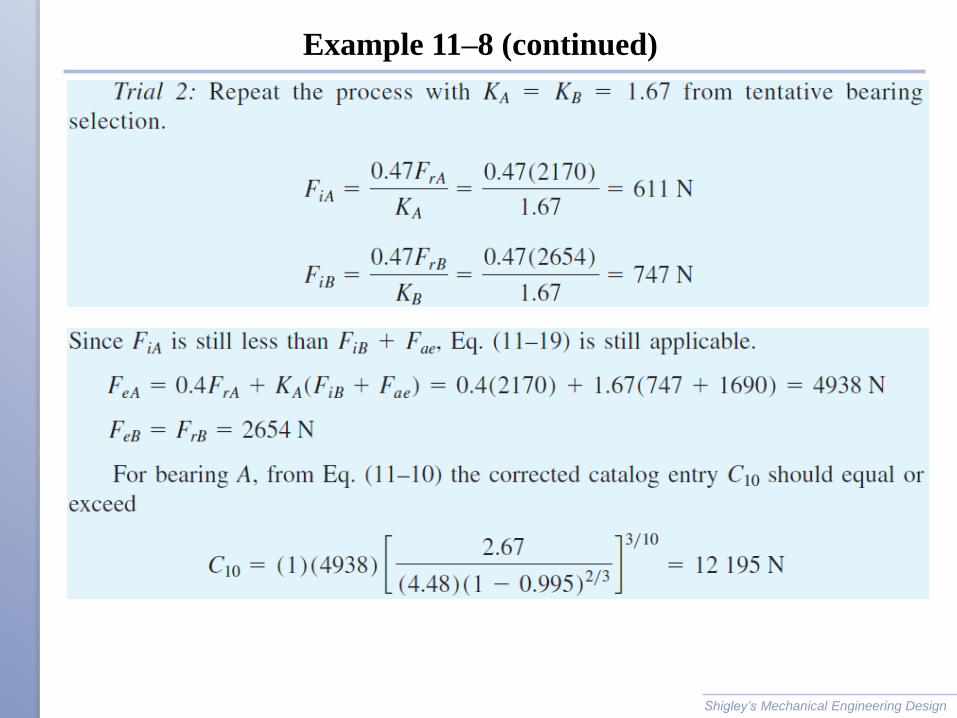
Example 11–8 (continued)
Shigley’s Mechanical Engineering Design Fig. 11–18
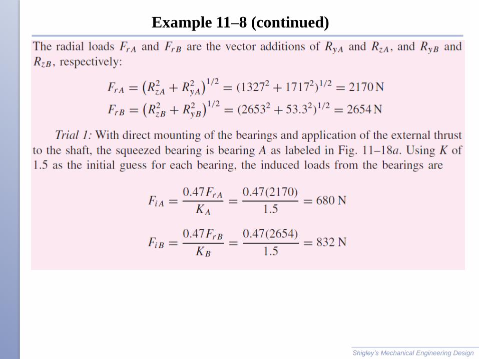
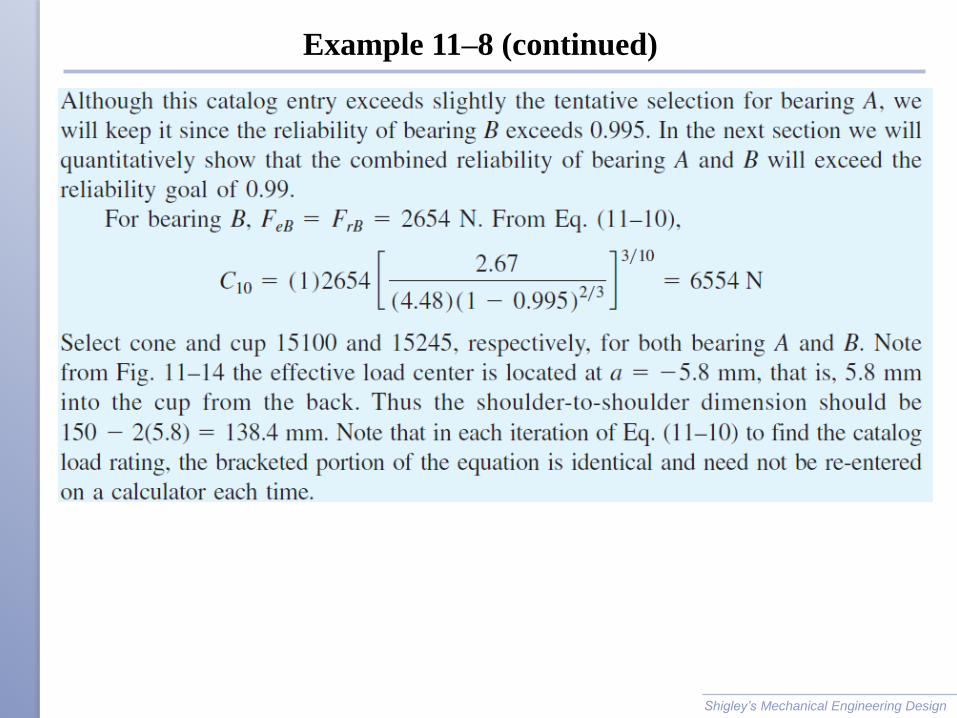
Example 11–8 (continued)
Shigley’s Mechanical Engineering Design
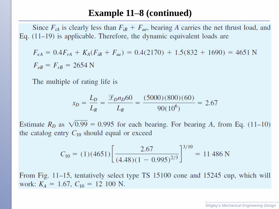
Example 11–8 (continued)
Shigley’s Mechanical Engineering Design
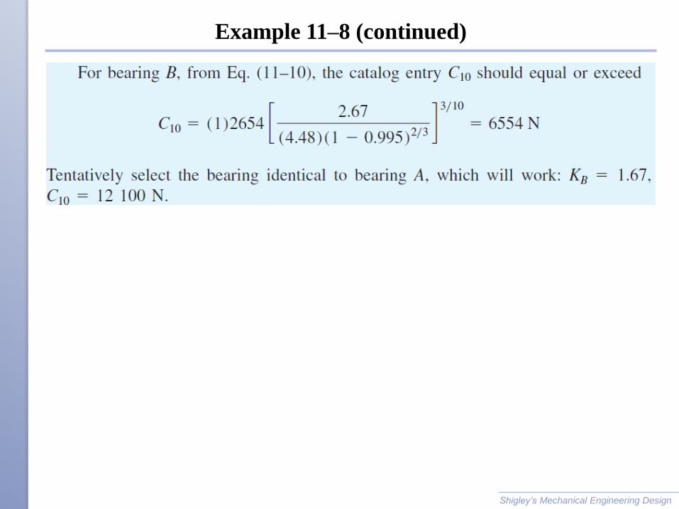
Example 11–8 (continued)
Shigley’s Mechanical Engineering Design
Example 11–8 (continued)
Shigley’s Mechanical Engineering Design
Example 11–8 (continued)
Shigley’s Mechanical Engineering Design
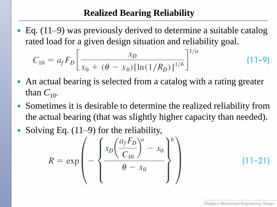
Realized Bearing Reliability
Eq. (11–9) was previously derived to determine a suitable catalog
rated load for a given design situation and reliability goal.
An actual bearing is selected from a catalog with a rating greater
than C10.
Sometimes it is desirable to determine the realized reliability from
the actual bearing (that was slightly higher capacity than needed).
Solving Eq. (11–9) for the reliability,
Shigley’s Mechanical Engineering Design
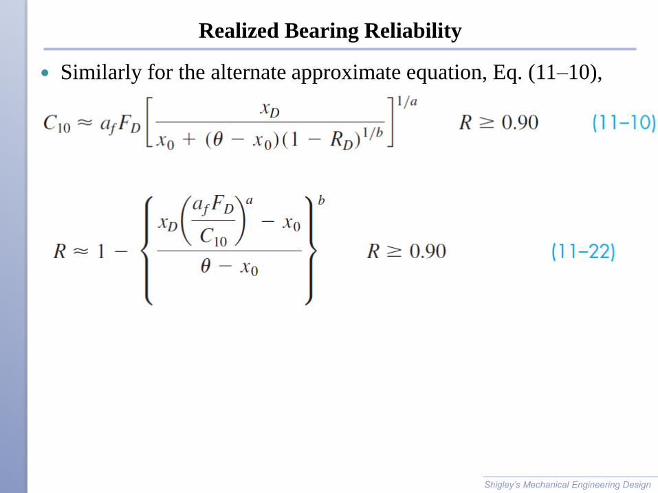
Realized Bearing Reliability
Similarly for the alternate approximate equation, Eq. (11–10),
Shigley’s Mechanical Engineering Design

Example 11–9
Shigley’s Mechanical Engineering Design
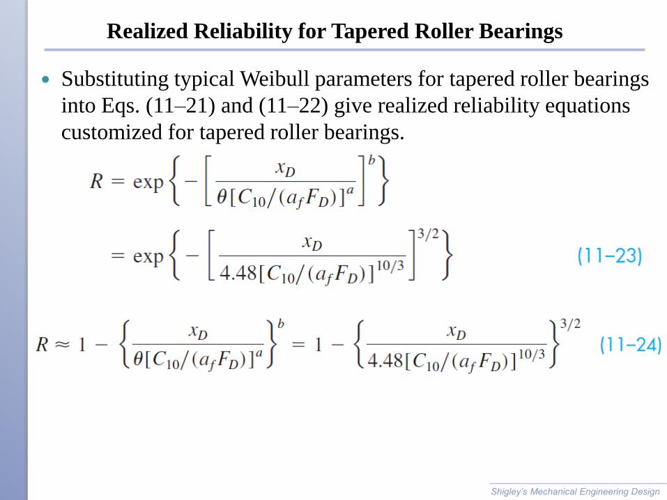
Realized Reliability for Tapered Roller Bearings
Substituting typical Weibull parameters for tapered roller bearings
into Eqs. (11–21) and (11–22) give realized reliability equations
customized for tapered roller bearings.
Shigley’s Mechanical Engineering Design
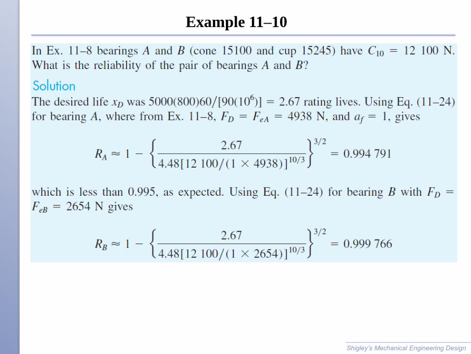
Example 11–10
Shigley’s Mechanical Engineering Design
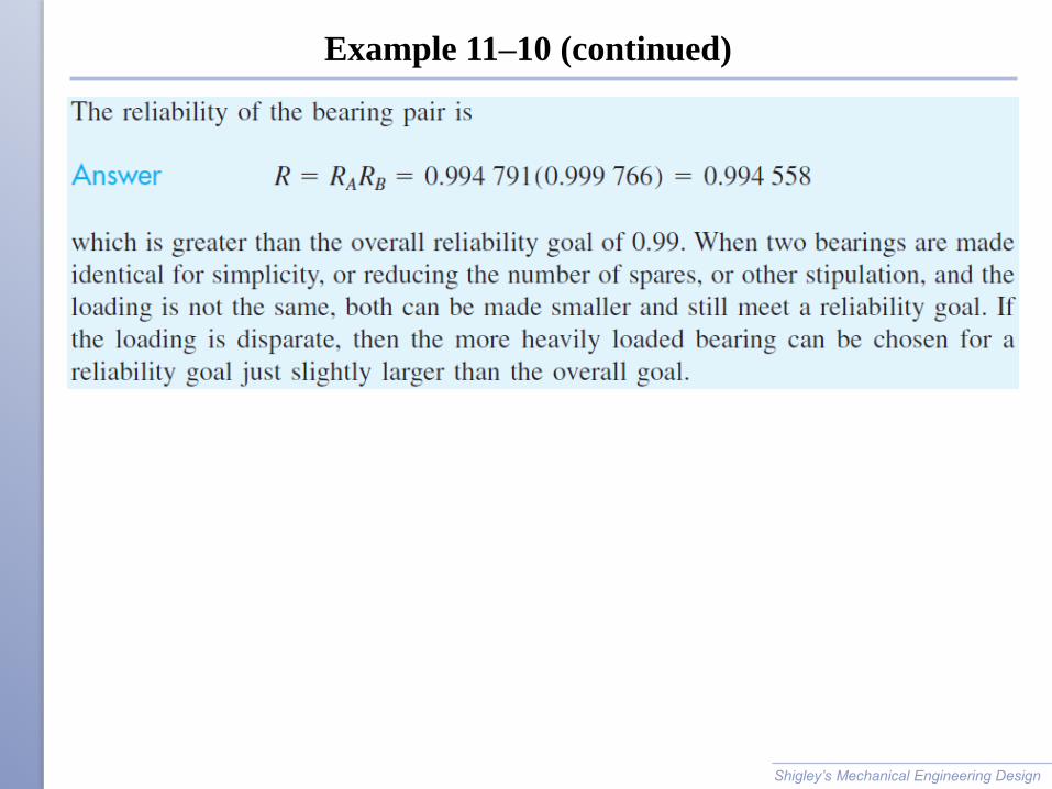
Example 11–10 (continued)
Shigley’s Mechanical Engineering Design
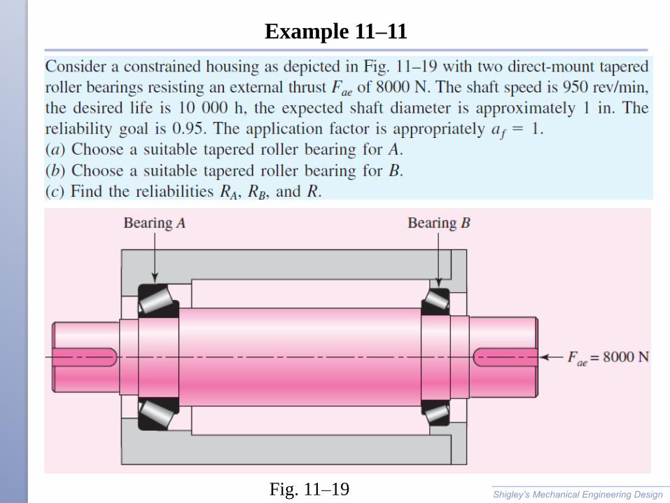
Example 11–11
Shigley’s Mechanical Engineering Design Fig. 11–19
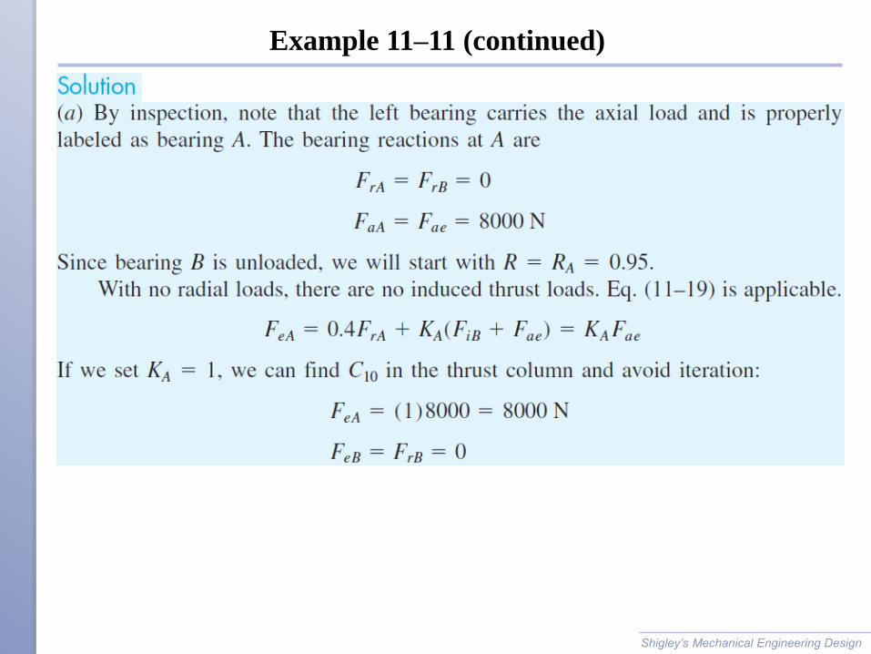
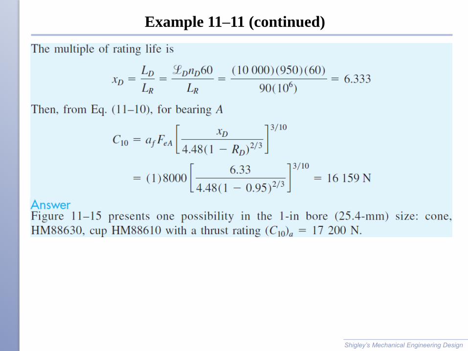
Example 11–11 (continued)
Shigley’s Mechanical Engineering Design
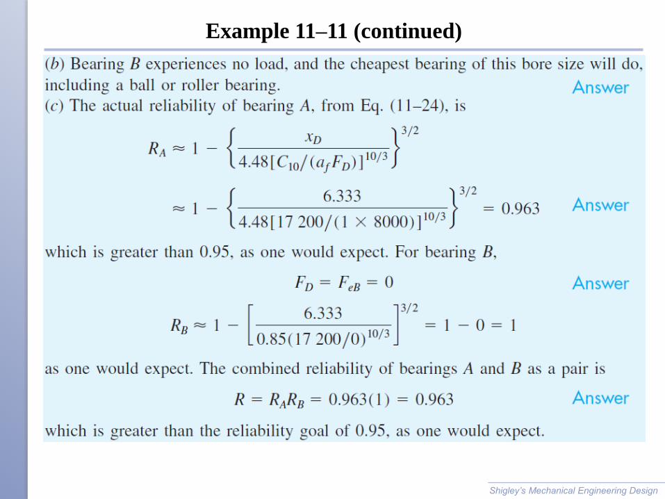
Example 11–11 (continued)
Shigley’s Mechanical Engineering Design
Example 11–11 (continued)
Shigley’s Mechanical Engineering Design
Bearing Lubrication
The purposes of bearing lubrication
◦ To provide a film of lubricant between the sliding and rolling
surfaces
◦ To help distribute and dissipate heat
◦ To prevent corrosion of the bearing surfaces
◦ To protect the parts from the entrance of foreign matter
Shigley’s Mechanical Engineering Design
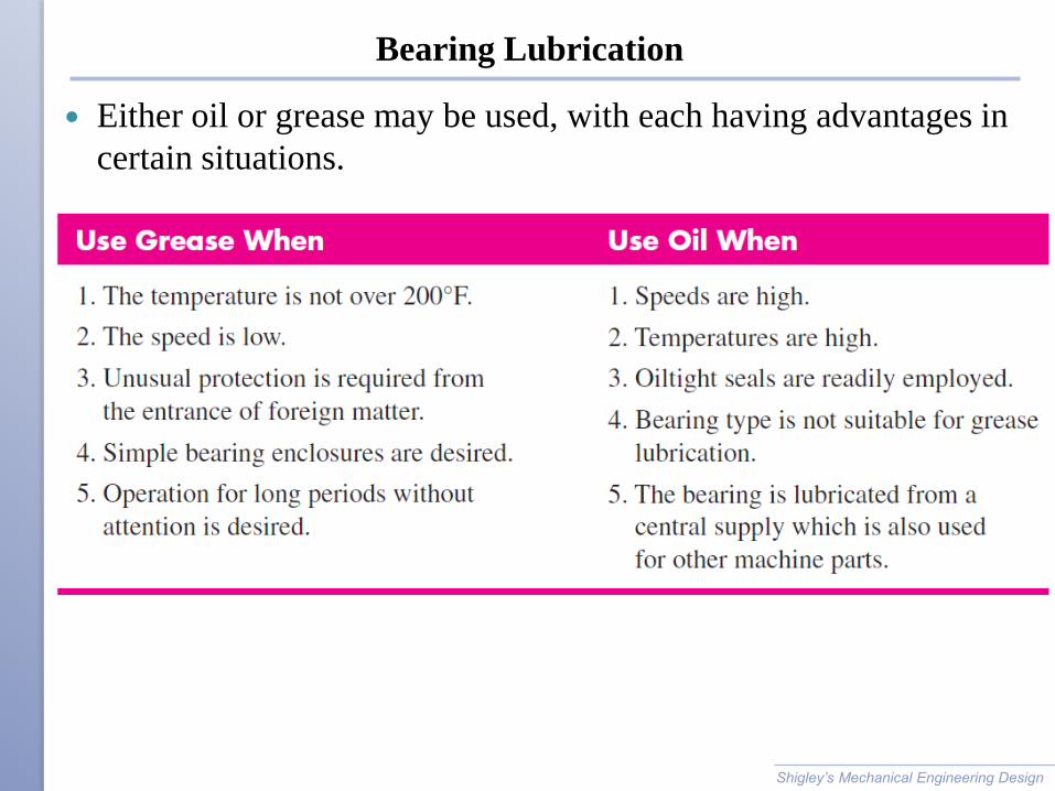
Bearing Lubrication
Either oil or grease may be used, with each having advantages in
certain situations.
Shigley’s Mechanical Engineering Design
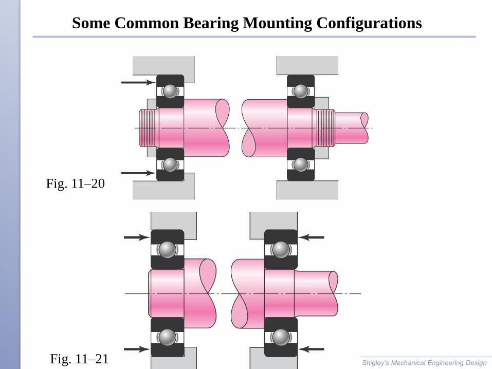
Some Common Bearing Mounting Configurations
Shigley’s Mechanical Engineering Design
Fig. 11–20
Fig. 11–21
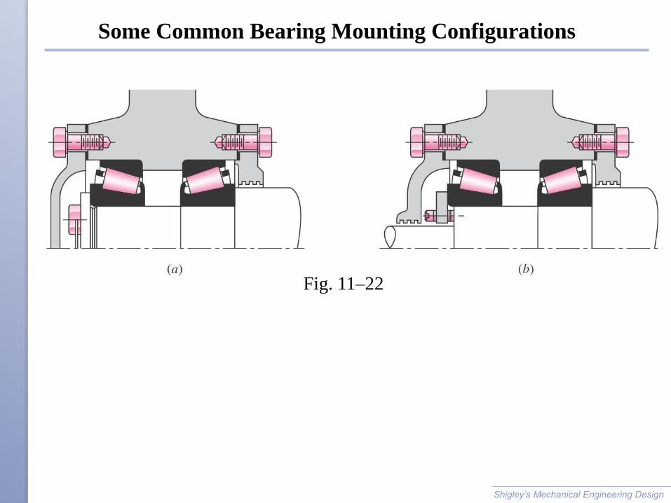
Some Common Bearing Mounting Configurations
Shigley’s Mechanical Engineering Design
Fig. 11–22
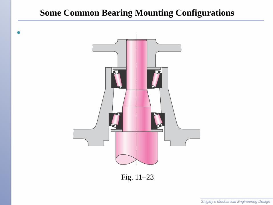
Some Common Bearing Mounting Configurations
Shigley’s Mechanical Engineering Design
Fig. 11–23
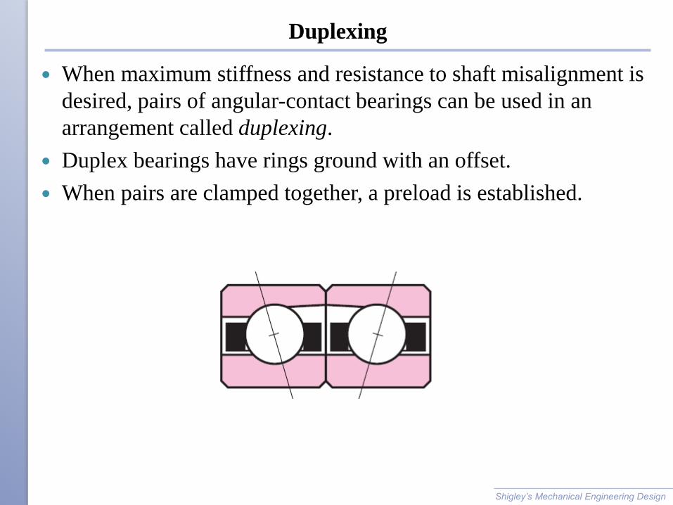
Duplexing
When maximum stiffness and resistance to shaft misalignment is
desired, pairs of angular-contact bearings can be used in an
arrangement called duplexing.
Duplex bearings have rings ground with an offset.
When pairs are clamped together, a preload is established.
Shigley’s Mechanical Engineering Design
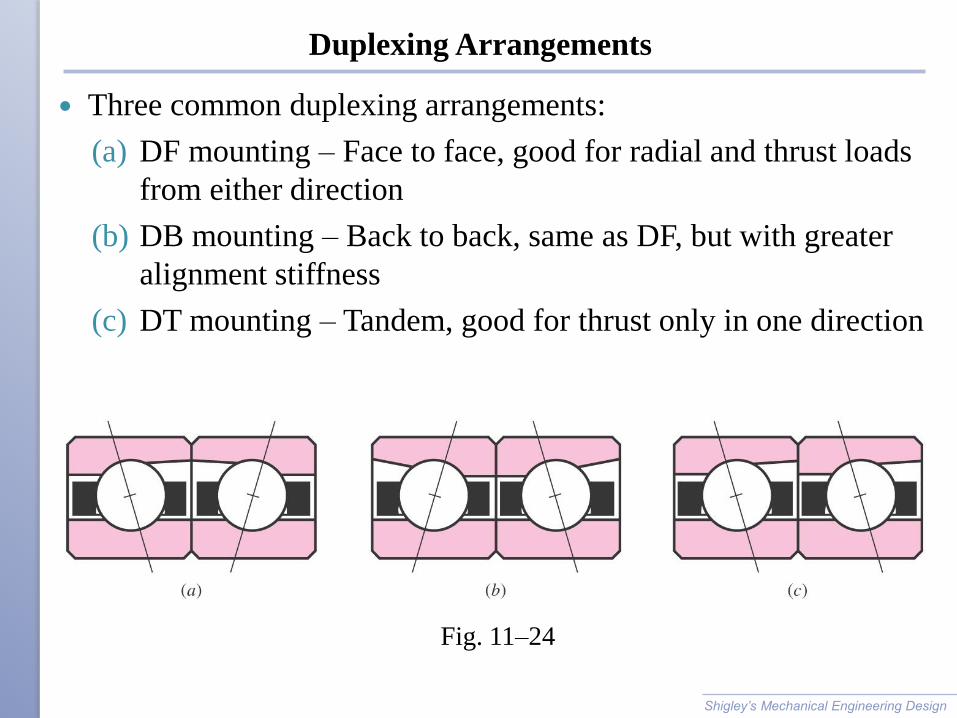
Duplexing Arrangements
Three common duplexing arrangements:
(a) DF mounting – Face to face, good for radial and thrust loads
from either direction
(b) DB mounting – Back to back, same as DF, but with greater
alignment stiffness
(c) DT mounting – Tandem, good for thrust only in one direction
Shigley’s Mechanical Engineering Design
Fig. 11–24
Preferred Fits
Rotating ring usually requires a press fit
Stationary ring usually best with a push fit
Allows stationary ring to creep, bringing new portions into the
load-bearing zone to equalize wear
Shigley’s Mechanical Engineering Design
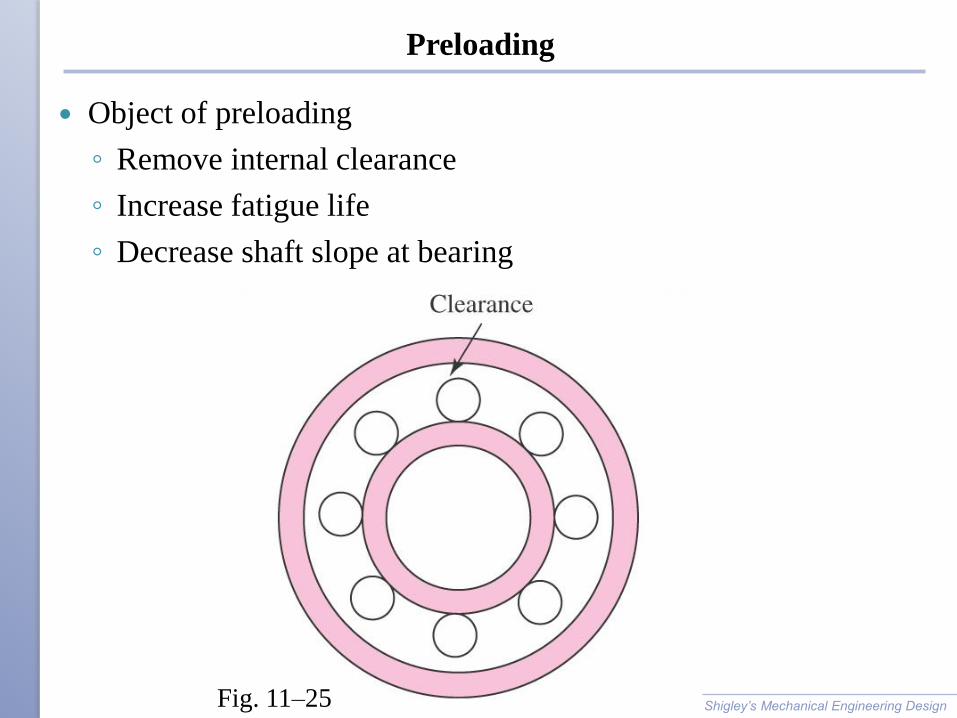
Preloading
Object of preloading
◦ Remove internal clearance
◦ Increase fatigue life
◦ Decrease shaft slope at bearing
Shigley’s Mechanical Engineering Design Fig. 11–25
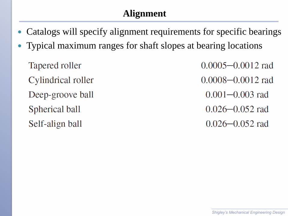
Alignment
Catalogs will specify alignment requirements for specific bearings
Typical maximum ranges for shaft slopes at bearing locations
Shigley’s Mechanical Engineering Design
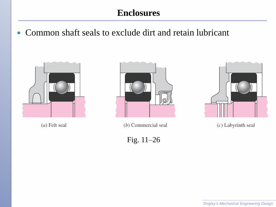
Enclosures
Common shaft seals to exclude dirt and retain lubricant
Shigley’s Mechanical Engineering Design
Fig. 11–26
DR. HAFTIRMAN
School of Mechatronic UniMAP
ENT345 MECHANICAL COMPONENTS
DESIGN SEM1-2015/2016
110
THANK YOU