Embed Size (px)
Citation preview

Diplomarbeit
Enhancing an Open Source UML Editor byContext-Based Constraints for Components
Martin Skinner
12th December 2001
Fachgruppe Computerunterstutzte Informationssysteme (CIS)Institut fur Softwaretechnik und Theoretische Informatik
Fakultat IV Elektrotechnik und InformatikTechnische Universitat Berlin
Betreuer: Felix BublGutachter: Prof. Dr. Herbert Weber, Dr. Ralf-Detlef Kutsche

Hiermit erklare ich an Eides Statt, dass ich die vorliegende Arbeitselbstandig und ohne unerlaubte fremde Hilfe angefertigt, andereals die angegebenen Quellen und Hilfsmittel nicht benutzt und die
den Quellen wortlich oder inhaltlich entnommene Stellen als solchekenntlich gemacht habe.

Abstract:
Before starting a detailed design, a specification model of the component-based sys-tem assists the software developer in early problem detection as soon as possible in thedevelopment process. The Component Constraint Language (CCL) developed by CIS atthe Technical University Berlin enables the developer to add context-based constraints(CoCons) to a component specification model. This produces a model which goes be-yond the simple description of the system’s static structure. At this time, there is notool to integrate the component specification model into the development process. Theprimary goal of this master’s thesis was to design such a tool, thereby supporting theContinuous Software Engineering (CSE) philosophy.
The open source modelling tool ArgoUML serves as a starting point. ArgoUMLis enhanced with a plugin mechanism, transforming the previously monolithic appli-cation into a component-based system, allowing pluggable components (plugins) to bedeveloped independently from the application. This mechanism is then used to extendArgoUML with a plugin supporting the CCL concepts.
Zusammenfassung:
Noch vor der Erstellung eines detaillierten Entwurfs hilft ein Spezifikationsmodelleines komponenten-basierten Systems dabei, Probleme so fruh im Entwicklungsprozeßwie moglich zu entdecken. Die Sprache CCL (‘Component Constraint Language’) wurdebei CIS, Technische Universitat Berlin, entwickelt und erlaubt den Entwickler ‘Context-based Constraints’ dem Spezifikationsmodell hinzuzufugen. Dadurch entsteht ein Mod-ell, das uber die Beschreibung der statischen Struktur des Systems hinausgeht. Zur Zeitexistiert allerdings kein Werkzeug, das das Komponentenspezifikationsmodell in den En-twicklungsprozeß integriert. Ziel dieser Diplomarbeit war der Entwurf eines solchenWerkzeugs, um die Philosophie des Continuous Software Engineering (CSE) zu unter-stutzten.
Das Open-Source Modellierungswerkzeug ArgoUML dient als Ausgangspunkt. Miteinem Plugin-Mechanismus wird ArgoUML von einer monolithischen Applikation ineinem komponenenten-basierten System umgewandelt. Dadurch konnen austauchbareKomponenten (plugins) unabhangig von der Applikation entwickelt werden. DiesesMechanismus wird dann verwendet um ArgoUML mittels eines Plugins um die CCL-Konzepte zu erweitertern.
This document is available online at http://www.cocons.org

Contents
I. Base Technologies and Methods 9
1. Software Components and Context-Based Constraints 101.1. The Component Constraint Language CCL . . . . . . . . . . . . . . . . . 111.2. Component Specification and the Unified Modeling Language . . . . . . . 121.3. Enhanced Global Business Type Diagrams . . . . . . . . . . . . . . . . . . 121.4. Enhanced Component Specification Diagrams . . . . . . . . . . . . . . . . 131.5. Enhanced Interface Specification Diagrams . . . . . . . . . . . . . . . . . 13
2. Integrating the Component Constraint Language in UML 162.1. The Unified Modelling Language . . . . . . . . . . . . . . . . . . . . . . . 162.2. Context Properties in UML . . . . . . . . . . . . . . . . . . . . . . . . . . 172.3. Context-based Constraints in UML . . . . . . . . . . . . . . . . . . . . . . 18
3. Software Design Patterns 193.1. Observer Pattern . . . . . . . . . . . . . . . . . . . . . . . . . . . . . . . . 193.2. Adapter Pattern . . . . . . . . . . . . . . . . . . . . . . . . . . . . . . . . 193.3. Singelton Pattern . . . . . . . . . . . . . . . . . . . . . . . . . . . . . . . . 213.4. Abstract Factory and Factory Method Patterns . . . . . . . . . . . . . . . 213.5. Composite Pattern . . . . . . . . . . . . . . . . . . . . . . . . . . . . . . . 213.6. Model View Controller . . . . . . . . . . . . . . . . . . . . . . . . . . . . . 23
4. XML – The eXtensible Markup Language 254.1. XML and Metadata . . . . . . . . . . . . . . . . . . . . . . . . . . . . . . 25
5. Unit Testing 275.1. The Java Unit Testing Framework JUnit . . . . . . . . . . . . . . . . . . . 28
II. Analysis of ArgoUML 30
6. The UML Metamodel Library NSUML 316.1. Primitives . . . . . . . . . . . . . . . . . . . . . . . . . . . . . . . . . . . . 326.2. Enumerations . . . . . . . . . . . . . . . . . . . . . . . . . . . . . . . . . . 326.3. Datatypes . . . . . . . . . . . . . . . . . . . . . . . . . . . . . . . . . . . . 34
4

6.4. Elements . . . . . . . . . . . . . . . . . . . . . . . . . . . . . . . . . . . . 346.5. Accessing and modifying metaattributes . . . . . . . . . . . . . . . . . . . 356.6. Accessing and modifying metaassociations . . . . . . . . . . . . . . . . . . 356.7. NSUML reflective API . . . . . . . . . . . . . . . . . . . . . . . . . . . . . 376.8. NSUML event notification . . . . . . . . . . . . . . . . . . . . . . . . . . . 386.9. NSUML undo/redo support . . . . . . . . . . . . . . . . . . . . . . . . . . 396.10. Model Persistance . . . . . . . . . . . . . . . . . . . . . . . . . . . . . . . 40
7. The Graph Editing Framework Library GEF 427.1. GEF View Architecture . . . . . . . . . . . . . . . . . . . . . . . . . . . . 427.2. GEF Controller Architecture . . . . . . . . . . . . . . . . . . . . . . . . . 42
7.2.1. GEF command classes . . . . . . . . . . . . . . . . . . . . . . . . . 447.2.2. GEF Editing Modes . . . . . . . . . . . . . . . . . . . . . . . . . . 447.2.3. GEF Selection classes . . . . . . . . . . . . . . . . . . . . . . . . . 46
7.3. Diagram Persistance . . . . . . . . . . . . . . . . . . . . . . . . . . . . . . 47
8. ArgoUML Architecture 498.1. The UML Diagrams . . . . . . . . . . . . . . . . . . . . . . . . . . . . . . 498.2. The Details Pane . . . . . . . . . . . . . . . . . . . . . . . . . . . . . . . . 538.3. The Navigator Pane . . . . . . . . . . . . . . . . . . . . . . . . . . . . . . 548.4. The Design Critics . . . . . . . . . . . . . . . . . . . . . . . . . . . . . . . 568.5. The ArgoUML project . . . . . . . . . . . . . . . . . . . . . . . . . . . . . 57
III. The CCL Modelling Tool 59
9. Extending the ArgoUML Modelling Tool 609.1. Adding a Plugin Mechanism . . . . . . . . . . . . . . . . . . . . . . . . . . 609.2. Avoiding source dependency . . . . . . . . . . . . . . . . . . . . . . . . . . 629.3. Avoiding distribution dependency . . . . . . . . . . . . . . . . . . . . . . . 639.4. Plugin dependencies . . . . . . . . . . . . . . . . . . . . . . . . . . . . . . 669.5. Limits . . . . . . . . . . . . . . . . . . . . . . . . . . . . . . . . . . . . . . 66
10.The CoCons Physical and Object Models 6710.1. Extending the NSML Library . . . . . . . . . . . . . . . . . . . . . . . . . 6710.2. The CoCons CCL Java Library . . . . . . . . . . . . . . . . . . . . . . . . 7110.3. CoCons Model Persistance . . . . . . . . . . . . . . . . . . . . . . . . . . . 72
10.3.1. Extending the UML-Document Type Definition . . . . . . . . . . . 7210.3.2. Writing XMI documents . . . . . . . . . . . . . . . . . . . . . . . . 75
10.4. Object Model Test Cases . . . . . . . . . . . . . . . . . . . . . . . . . . . 7510.4.1. Testing metaattributes . . . . . . . . . . . . . . . . . . . . . . . . . 7510.4.2. Testing metaassociations . . . . . . . . . . . . . . . . . . . . . . . . 7610.4.3. Testing persistance . . . . . . . . . . . . . . . . . . . . . . . . . . . 77
5

11.The CCL Editor Diagrams 7911.1. The Figure Classes . . . . . . . . . . . . . . . . . . . . . . . . . . . . . . . 80
11.1.1. The Context-based Constraint Figure . . . . . . . . . . . . . . . . 8311.1.2. The Context Condition Subfigure . . . . . . . . . . . . . . . . . . . 8411.1.3. The Context Elements Subfigure . . . . . . . . . . . . . . . . . . . 8711.1.4. The Context Property Figure . . . . . . . . . . . . . . . . . . . . . 8711.1.5. The Component Spec and Interface Type Figure . . . . . . . . . . 8811.1.6. The Interface Dependency Figure . . . . . . . . . . . . . . . . . . . 90
11.2. The constraint diagram . . . . . . . . . . . . . . . . . . . . . . . . . . . . 9011.2.1. The Diagram class . . . . . . . . . . . . . . . . . . . . . . . . . . . 9011.2.2. The Graph Model . . . . . . . . . . . . . . . . . . . . . . . . . . . 9211.2.3. The Diagram Renderer . . . . . . . . . . . . . . . . . . . . . . . . 94
11.3. The business type diagram . . . . . . . . . . . . . . . . . . . . . . . . . . 9411.3.1. The Diagram class . . . . . . . . . . . . . . . . . . . . . . . . . . . 9511.3.2. The Graph Model . . . . . . . . . . . . . . . . . . . . . . . . . . . 9611.3.3. The Diagram Renderer . . . . . . . . . . . . . . . . . . . . . . . . 98
11.4. The component specification diagram . . . . . . . . . . . . . . . . . . . . 9811.4.1. The Diagram class . . . . . . . . . . . . . . . . . . . . . . . . . . . 9811.4.2. The Graph Model . . . . . . . . . . . . . . . . . . . . . . . . . . . 9911.4.3. The Diagram Renderer . . . . . . . . . . . . . . . . . . . . . . . . 99
11.5. The interface specification diagram . . . . . . . . . . . . . . . . . . . . . . 9911.5.1. The Diagram class . . . . . . . . . . . . . . . . . . . . . . . . . . . 10011.5.2. The Graph Model . . . . . . . . . . . . . . . . . . . . . . . . . . . 10011.5.3. The Diagram Renderer . . . . . . . . . . . . . . . . . . . . . . . . 101
11.6. The Diagram Actions . . . . . . . . . . . . . . . . . . . . . . . . . . . . . 10111.6.1. Creating Stereotyped Nodes . . . . . . . . . . . . . . . . . . . . . . 10111.6.2. Creating Stereotyped Edges . . . . . . . . . . . . . . . . . . . . . . 10111.6.3. Adding Context Properties . . . . . . . . . . . . . . . . . . . . . . 102
11.7. Integrating the diagrams in ArgoUML . . . . . . . . . . . . . . . . . . . . 102
12.Extending the ArgoUML Workspace 10412.1. Extending the Details Pane . . . . . . . . . . . . . . . . . . . . . . . . . . 104
12.1.1. The Tagged Values Tab . . . . . . . . . . . . . . . . . . . . . . . . 10612.1.2. The Stereotype Property Panel . . . . . . . . . . . . . . . . . . . . 10612.1.3. The Context-based Constraint Property Panel . . . . . . . . . . . 10712.1.4. The Context Condition Property Panel . . . . . . . . . . . . . . . 10812.1.5. The Tag Definition Property Panel . . . . . . . . . . . . . . . . . . 10912.1.6. The ContextProperyTag Property Panel . . . . . . . . . . . . . . . 109
12.2. Extending the Navigator Pane . . . . . . . . . . . . . . . . . . . . . . . . 11012.3. Adding new Design Critics . . . . . . . . . . . . . . . . . . . . . . . . . . . 11112.4. Plugin Initialization . . . . . . . . . . . . . . . . . . . . . . . . . . . . . . 112
13.Conclusion 115
6

A. Necessary Source Modifications 116A.1. Bugfix in package ru.novosoft.uml.undo . . . . . . . . . . . . . . . . . . . 116A.2. Modifications to the ArgoUML sources . . . . . . . . . . . . . . . . . . . . 116
A.2.1. The plugin package . . . . . . . . . . . . . . . . . . . . . . . . . . . 117A.2.2. Accessing the Application Menu Bar . . . . . . . . . . . . . . . . . 118A.2.3. Extendable Property Panels . . . . . . . . . . . . . . . . . . . . . . 118A.2.4. The extended NSUML library . . . . . . . . . . . . . . . . . . . . . 118
7

Introduction
Changing requirements is a major challange to software development. The componentapproach needs to address this issue – by designing for change. Properly done, compo-nents become replaceable with limited impact on the rest on the system.
Before starting detailed design, a specification model of the component-based systemassists the software developer in early problem detection as soon as possible in thedevelopment process. With the use of the Component Constraint Language (CCL), thedeveloper can enrich his specification model with context-based constraints (CoCons),producing a component specification model which goes beyond the simple description ofthe systems static structure.
At this time, there is no tool to integrate the component specification model into thedevelopment process. The goal of this work was to design such an tool. The resultingdesign document should lay the groundwork for the development of a software modellingtool which supports the continuous software engineering (CSE) perspective includinggraphical representation and editing of the component specification model in the visuallanguage CCL and support for verification of CoCons during modifications of the model.In order to avoid ‘re-inventing the wheel’, the open source modelling tool ArgoUML wasselected as a starting point. It contains support for many concepts every modelling toolsrequires.
This work is divided into three main parts. The first part gives a short introductionto the base technologies and methods the reader should be familiar with in order to fullyunderstand this work.
An analysis of the ArgoUML architecture is a prerequisite to extending the ArgoUMLapplication. A detailed, in-depth description of the ArgoUML internals would go beyondthe scope of this work, so the second part focuses on the high-level view of the architectureand goes into a more detailed perspective only when necessary.
The third part is a detailed design document describing how ArgoUML can be mod-ifed to support pluggable components (’plugins’), and how a plugin supporting the newmodelling concepts introduced in CCL can be implemented.
8

Part I.
Base Technologies and Methods
9

1. Software Components andContext-Based Constraints
Software components can be considered as building blocks from which complex systemsare constructed. Components share some of the fundamental principles of object tech-nology:
Unification of data and function each component consists of data values (which formits state) and the functions that access this data.
Encapsulation the client needs no knowledge of the component’s implementation, onlyits specification.
Identity each component is unique identifiable. Two different components could havethe same state (which means they could be considered equal in value) but still havetheir own identities.
But components are not simply objects – some differences include:
Component Infrastructure in order for components to be able to interact, there mustbe some basic standard on which inter-component communication is built. Somereal-world examples are COM+, Enterprise Java Beans (EJB) and CORBA.
Component Interfaces build on the concept of encapsulation by adding another levelof indirection: A client does not depend on a component, but on a component’sinterface. This means that a component can be replaced by another componentoffering a ‘compatible interface’ without having to change the clients.
Interface Specification the notion of a ‘compatible interface’ is dictated by the interfacespecification. Depending on the infrastructure, an exported interface could beconsidered compatible if the services offered are a superset of the services requested.
Component Specification since clients access components only through their interfaces,the specification of a component is reduced to the interfaces it offers (exports) andthe interfaces it uses (imports).
Component Architecture the structual relationships between components and their be-havioral dependencies.
10
Supplier Component
Client Component
Interface
Figure 1.1.: A simple component architecture
This new level of indirection makes components replaceable – and underlines the dif-ferent goals of component-based and object-oriented approaches: while object-orienteddesigns promise the reusablity of its subsystems, component-based architectures promisethe replaceability of individual components. The internals of a component may very wellbe implemented with an object-oriented language. Most component infrastructures en-capsulate the implementation so well as to allow different components to be implementedin different languages – but component implementation is beyond the scope of the work.
1.1. The Component Constraint Language CCL
The specification of components and interfaces can exists on many levels: some formal,some informal. The simplest form of formal specification is the purely syntactical spec-ification: do the function name and parameters the client use match the signature ofthe function offered? The most flexible form is the specification in a natural language:although sometimes unavoidable, this can lead to ambiguity.
Constraints lie somewhere in the middle. An example of a constraint is ‘a customermust have a name’. A constraint is usually expressed in a formal language as an invari-ant which must be fulfilled whenever the system is in a stable state. The above example,expressed in a formal constraint language could be ‘Customer.name->notEmpty’. By us-ing a formal language it becomes possible to automatically check whether all constraintsare fulfilled.
This constraint applies to a single, directly specified model element: Customer. Thecomponent constraint language (CCL) adds a new kind of constraint where it is possibleto specify model elements indirectly. The basic idea is to add context-properties tomodel elements which hold meta-information about the model element. A context-basedconstraint (CoCon) uses these context properties to identify to which model elements it
11

applies. It then becomes possible to specify ‘all model elements with the context-propertyPersonalData are unreadable by the component WebServer’.
1.2. Component Specification and the Unified Modeling
Language
Although the Unified Modelling Language (UML) includes the notion of ‘component’, itis not the same as the component handled here. The UML definition is:
A component type represents a distributable piece of implementation of asystem, including software code (source, binary, or executable) but also in-cluding business documents, etc. in a human system. [...] A componentinstance represents a run-time implementation unit and may be used to showimplementation units that have identity at run-time, including their locationon nodes. [UML1.3, 3.97.1]
Clearly, this is focused on the distribution and deployment of components and hasnothing to do with the specification of components, which is the focus of this work.UML was designed to describe object-oriented analysis and design, and doesn’t describecomponent-based systems very well. One possibility of expressing the specification ofcomponents in a component architecture with UML can be found in [Cheesman+2001].This ‘UML Components’ approach is used in this work, although other approaches arecertainly possible.
In this approach, static structure diagrams (informally known as class diagrams)are used to model component specification. Stereotypes are used to indicate that theclasses represent specification-level entities – these are specification models, not im-plementation models. The following sections describe the various specification modelsused in [Cheesman+2001] and enhance them with the context-properties introduced in[Bubl2001-CCL].
1.3. Enhanced Global Business Type Diagrams
Business type diagrams [Bubl2001-CCL, section 2.2] show the business types which are inthe domain of the system. Business types represent the data objects which are exchangedbetween the components in a system.
Enhanced business type digrams are modeled using a subset of the UML static struc-ture diagrams enhanced with context properties from the CoCons metamodel. Businesstypes are represented by the UML Class metaclass but have less detail – there areno methods and the attributes are not yet fully defined. To set them apart from nor-mal implementation classes, they always have a stereotype such as <<type>> or <<infotype>>. Each business type can have context properties – represented by rectangleswith crossed corners.
12

<<type>>Customer
customerID: Integername: StringlegalForm: String
Workflow: NewContact, NewCustomer
PersonalData: Yes
Figure 1.2.: Enhanced global business type diagram
PersonalData: Yes
<<comp spec>>CustomerManagement ICustomerMgt
IAddressMgt
Figure 1.3.: Enhanced Component Specification Diagram
1.4. Enhanced Component Specification Diagrams
Component specification diagrams show what interfaces components offer (export) andwhat they assume are available (import). This diagram type is not the same as theUML component deployment diagram which is geared towards implementation and de-ployment of components. The focus of this diagram is the specification of components.For this reason, they not modeled using the UML Component metaclass, but with theClass metaclass having the stereotype <<comp spec>>. As with business types dia-grams, components specifications may also have context properties.
The interfaces are also represented by the Class metaclass, but have the stereo-type <<interface type>>. In the diagram they are depicted with the usual ‘lollipop’notation.
1.5. Enhanced Interface Specification Diagrams
These diagram further refine the interfaces used in component specification diagrams.They specify which methods are part of the interface and what business types (or info-mation types1) are required by the methods. Note that the <<interface type>> classes
1according to [Cheesman+2001, 3.8.2], information types are ‘views’ on a business type, containingonly the information a certain interface cares about
13

createCustomer(in customerName, in legalForm, out customerID)
setCustomerAddress(in customerID, in addressID)deleteCustomer(in customerID)
ICustomerMgt<<interface type>>
PersonalData: Yes
<<info type>>Customer
customerID: Integername: StringlegalForm: String
<<info type>>Address
addressID: Integer
Figure 1.4.: Enhanced interface specification diagram
14

in this diagram are the same model elements as the those in the enhanced componentspecification diagram – they are simply rendered differently and in more detail.
15

2. Integrating the Component ConstraintLanguage in UML
The Component Constraint Language is a graphical as well as a textual notatation fordescribing context-based constraints. Although CCL is an independent langauge, it ispossible to combine it with other modelling languages. This chapter describes how CCLcan be integrated in the Unified Modelling Language.
2.1. The Unified Modelling Language
The Unified Modeling Language (UML) provides system architects workingon object analysis and design with one consistent language for specifying,visualizing, constructing, and documenting the artifacts of software systems,as well as for business modeling.[UML1.3, introduction]
The Object Management Group (OMG) describes a four-level metadata architecture[XMI1.1, section 1.2.1] known as the Meta Object Facility (MOF). This is the OMG’sstandard for defining, representing and managing metadata. The MOF-Model (the meta-metamodel) resides on the level with the highest abstraction. This describes the basicbuilding blocks from which metamodels are constructed.
UML is a M2-metamodel – it can be described with MOF-model and can describeuser level (M1) models. UML defines metaclasses such as classes, associations, statesand transitions which the system architect uses to describe his system.
UML 1.3 is the most widely accepted and supported version, and although version 1.4of the specification has been released in September 2001, most of the available modelling
MOF−Model
Metamodels
Models
Data
M3 Level
M2 Level
M0 Level
M1 Level
Figure 2.1.: MOF 4-Level Metadata Architecture
16

Figure 2.2.: Simplified CCL metamodel
tools do not yet support this version.Not all of the CCL concepts can be described with the UML metamodel. For this
reason, the UML 1.4 metamodel has been extended with the elements shown in figure2.2. The following sections describe the semantics of these new elements.
2.2. Context Properties in UML
As described in 1.1, model elements can be enriched with context properites. When usingUML, context properties are modeled using UML 1.4 tagged values. As with all taggedvalues, context properites are defined by their type – which must be a context propertytag. Since ContextPropertyTag is derived from TagDefinition, each context propertytag must be owned by a stereotype1. This means that the stereotype of a model elementdetermines what context properties the model element may have. The context propertytag also has a value validation, a constraint which further defines what combination ofcontext properties are valid. The following example will illustrate these relations:
1. The stereotype <<comp spec>> has the base class ‘class’, so it can only be usedon classes.
1Although the UML 1.4 metamodel allows tag definitions not to have a stereotype, the UML 1.4specification explictly discourages this. Tag definitions not bound to a stereotype are only permittedfor UML 1.3 compatibility reasons.
17

PersonalData: Yes
WebServer
<<comp spec>>
UnreadableByi?
Figure 2.3.: Context-based constraint diagram
2. This stereotype has a defined tag (a context property tag) with name=’Tier’
3. This context property tag has the tagType=’{”Business Process”, ”Internet”, ”un-known”}’ and multiplicity=’*’ (a component may be in more than one tiers).
4. This context property tag also has a value validation which specifies that the value‘unknown’ may not be used in combination with the other possible values (if thetier is unknown, no other value may be specified).
All of this specifies that classes with the stereotype <<comp spec>> (1) may have acontext property ’Tier’ (2). This context property can have any number of values outof {”Business Process”, ”Internet”, ”unknown”} (3), but if the value ‘unknown’ is used,it must be used alone (4).
2.3. Context-based Constraints in UML
CCL introduces a new type of constraint, the context-based constraint (CoCon). EachCoCon consists of constrained elements, scoped elements and a constraint body. Theconstrained elements and the scope elements may either be specified directly (through areference) or indirectly (through a context condition).
Figure 2.3 shows a CoCon which specifies that any model element with the contextproperty ‘Personal Data’ with the value ‘Yes’ may not be readable by the class ’Web-Server’. This example illustrates the power of CoCons: the constrainted elements arespecified indirecty by the context condition ‘Personal Data: Yes’.
Context-based constraints have both a textual and a graphical notation. The de-tails of these notations can be found in [Bubl2001-CCL]. A new type of diagram, theconstraint diagram, shows the context-based constraints in their graphical form.
18
3. Software Design Patterns
All well-structured object-oriented architectures are full of patterns. Indeed,one of the ways that I measure the quality of an object-oriented system is tojudge whether or not its developers have paid careful attention to the commoncollaborations among its objects. Focusing on such mechanisms during asystem’s development can yield an architecture that is smaller, simpler, andfar more understandable than if these pattern are ignored.
Grady Booch [Gamma+95, Forward]
Is this aspect, ArgoUML is no exception, making extensive use of various design patterns.The following sections give short descriptions of some of the design patterns which havebe used in ArgoUML.
The diagrams are not identical to those in [Gamma+95] – they are now in UMLnotation and reflect certain aspects of the Java language (e.g. interfaces).
3.1. Observer Pattern
The observer pattern [Gamma+95, p. 293] is one of the most useful design patterns.It allows one object (the subject, also known as observable) to notify other objects (theobservers, also called listeners) without making assumptions about who these objects areor how many exist. Through this pattern, there is an abstract coupling between subjectand observer – the subject has a set of observers, each realizing a simple interface. Theobservers need no knowledge of each other and the subject is not dependent on theconcrete observers.
The observers have to register themselves with the subject – from this point on (orat least until they are unregistered) they receive notification whenever the state of thesubject changes. Once being notified, the observers may act by inspecting the subjectand reacting accordingly.
3.2. Adapter Pattern
The adapter pattern [Gamma+95, p. 139] can be used to convert the interface of a class(or an entire class library) into another interface the clients expect. This allows classesto work together even if they have incompatible interfaces.
19

subj
+ Unregister(Observer)# Notify()
+ Register(Observer)
{abstract}Subject
+ Update()
Observer
<<interface>>
+ GetState()+ SetState()
ConcreteSubject
0..∗observes0..*
obs
+ Update()
ConcreteObserver
notifies 0..∗0..*
Figure 3.1.: Observer pattern
client
+request()
Adapter
adaptee
Adaptee<<interface>>
+specificRequest()
<<interface>>Target
+request()
Client
Figure 3.2.: Adapter pattern
20

Singelton
+theInstance : Singelton
−Singelton()+op()
static accessor
constructorprivate
Figure 3.3.: Singelton pattern
Clients can thus be used with unforseen classes – avoiding depencendies betweenclient and adapted class (Adaptee). The Adaptor translates and forwards calls from theclient to the Adaptee.
3.3. Singelton Pattern
Sometimes it is important that a class has only one instance. The singelton pattern[Gamma+95, page 127] is a way to ensure that the class is instatiated only once and allclient access this instance from a well-known access point.
This is achieved by declaring the constructor as private, preventing any other classfrom creating instances. The only access to this class is through a static member whichcreates the single instance upon initialization.
3.4. Abstract Factory and Factory Method Patterns
These creational patterns allow objects to be created without their concrete classeshaving to be specified.
A framework could, for example, use interfaces to specify a class hierarchy. Theframework can create new products by using the abstract factory and access these prod-ucts through their interfaces.
The application implements the factory methods to create the concrete products.Although the framework is able to create new products, it needs no knowledge of theapplication-specific classes.
3.5. Composite Pattern
The composite pattern [Gamma+95, p. 163] can be used to represent part-whole hier-archies. Clients can treat individual objects and compositions uniformly.
21

framework
Product_A<<interface>>
Product_B<<interface>>
+Product_A FactoryMethod_A()+Product_B FactoryMethod_B()
<<interface>>AbstractFactory
app
+Product_A FactoryMethod_A()+Product_B FactoryMethod_B()
ConcreteFactory
ConcreteProduct_A ConcreteProduct_B
Figure 3.4.: Abstract factory and factory method patterns
Client
+operation()
Composite
+add(Component)+remove(Component)+getChild(int)
+operation()
Leaf
+operation()+add(Component)+remove(Component)+getChild(int)
Component<<interface>>
child
Figure 3.5.: Composite pattern
22
Model
View
∗
∗
∗ ∗modifysController
updates
1
∗ notifys
interacts
User
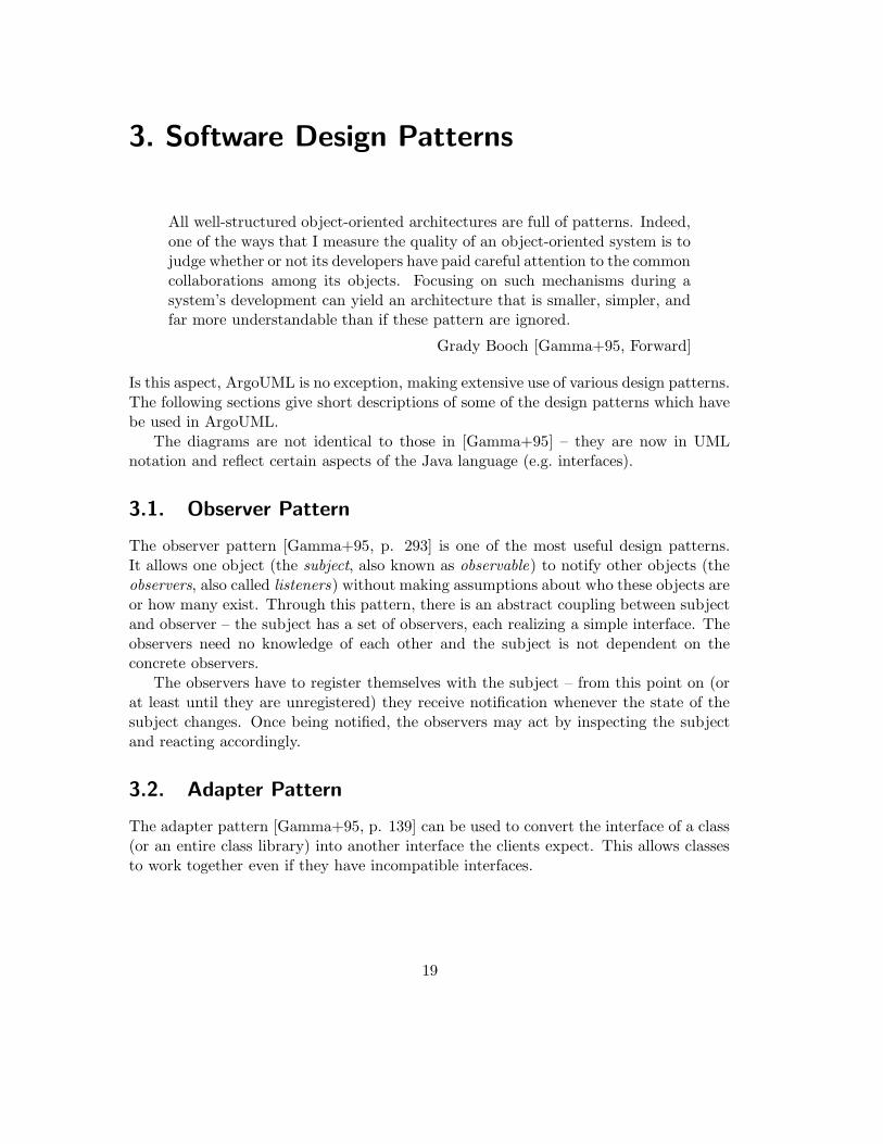
Figure 3.6.: Model-View-Controller pattern
The interface Component represents both single and composite objects. Clients usethe Component interface to interact with objects in the composite structure. If therecipient is a leaf, the call is processed directly. If the recipient is a composite, itrecursivly forwards the call to all its children. If there is some functionality commonto both leaves and compostites, it may be advantageous to implement Component as anabstract class.
3.6. Model View Controller
The Model-View-Controller (MVC) pattern decouples the visual representation of graphsfrom their data stucture. In the MVC pattern, the user interface (view and controller) isseperated from the data to be displayed and manipulated (model). A single model mayhave multiple views associated with it. In the case of a spreadsheet, the model may bea two dimensional array of values. A bar chart, a pie chart and a table with rows andcells are three views visualising the model in three different ways.
Views are associated with controllers that modify the model as necessary when theuser interacts with the view. The controller then calls the model’s mutator methods to
23

modify the model. The model then notifys all views of the change (using the observerpattern) so they always reflect the current state of the model.
24

4. XML – The eXtensible Markup Language
The eXtensbile Markup Language (XML) is the language of choice when describingand encoding structured data. XML is not a ‘fixed’ format like HTML (which is apredefined markup language), but can be considered a ‘meta-language’ which describesand specifies customized markup languages (XML applications, sometimes referred to asdocument types). These definitions are specified by Document Type Definition (DTD)files. There are already thousends of XML applications, some examples are:
XHTML is a modified form of the Hypertext Markup Language (HTML). The modifi-cations are necessary since some of the HTML syntax elements do not conform tothe XML syntax rules
XMI is a set of document types used to describe models. One example of an XMI-DTDis the UML-DTD.
MOF is part of the XMI specification and is used for describing metamodels.
SVG is a format for scalable 2D vector graphics
4.1. XML and Metadata
According to the XML Metadata Specification [XMI1.1], any MOF level 2 metamodel(such as UML) can be encoded in XML with the MOF-DTD. XMI also specifies howto generate a XMI-DTD from a MOF document. The resulting DTD describes how amodel (M1) should be structured when encoding in XMI. One example of this is theUML-DTD, which is included in the XMI specification.
In XMI-DTDs each class, attribute and role in the metamodel is represented byits own XML-element, for example: the attribute name of metaclass ModelElement isspecified as:
<!ELEMENT Foundation.Core.ModelElement.name
(#PCDATA | XMI.reference)*
>
XML−Document XML−DTDdescribes
* 1
Figure 4.1.: Relationship between XML and DTD documents
25

UML: MOF−document MOF−DTD: XML−DTD
UML−DTD: XMI−DTD:UML−document
describes
describes
generates
Figure 4.2.: Relationship between MOF and XMI
This defines a new XML-element named ‘Foundation.Core.ModelElement.name’, whichcontains parsed character data (i.e. text) or an XML-element named ‘XMI.reference’.
In an XML document, elements have a starting tag, their contents, and a closing tag.An XMI document conforming to this DTD could contain:
<Foundation.Core.ModelElement.name>
Customer
</Foundation.Core.ModelElement.name>
In some cases, the DTD makes use of XMI-attributes:
<!ELEMENT Foundation.Core.ModelElement.visibility
EMPTY
>
<!ATTLIST Foundation.Core.ModelElement.visibility
xmi.value ( public | private | protected )
#REQUIRED
>
This specifies that the XML-element should have no contents (EMPTY), but has oneXMI-attribute named ‘xmi.value’ which should have either ’public’, ’private’ or ’pro-tected’ as a value. XML attributes are included in the opening tag. In the XMI-Document, this would be:
<Foundation.Core.ModelElement.visibility
xmi.value="protected" >
</Foundation.Core.ModelElement.visibility>
Since this XML-element is empty, XML allows the opening and closing tag to be com-bined. In this shorthand notation, the above example would be:
<Foundation.Core.ModelElement.visibility
xmi.value="protected" />
26
5. Unit Testing
Extreme Programming (XP) is a relativly new and quite controversial method for devel-oping software. It consists mainly of twelve programming practices which reinforce eachother – the shortcommings of the individual practices are compensated by the strengthsof the others. According to [Beck2000, p. 69]:
‘Any one practice doesn’t stand well on its own (with the possible exceptionof testing). They require the other practices to keep them in balance’
XP relies on automated test routines to detect side-effects that can occur when refactor-ing code. Functional tests are written by (or with the help of) the customer to test therequirements of the system, and unit tests are written by the programmer to satisfy theprogrammer that the software does what he thinks it should do. Some of the criteria ofunit tests are:
• Test cases must be fully automated, requiring no user interaction.
• Each test case must be isolated, having no dependencies on other tests.
• The test cases should be kept simple, avoiding the necessity of debugging the unittest.
• Tests must be boolean, returning either ‘tested passed’ or ‘test failed’
• The unit tests should be called often – as much as once per build cycle. Since theunit tests are fully automated, it takes almost no effort to execute them.
• If a change in code causes a test to fail, the top priority is to fix the code so thatall unit tests pass. A test suite where 99% of the tests pass is still a failure.
• Unit tests which test what a method should do should be written first – then themethod should be implemented so that it passes the test.
• Whenever a bug is discovered which is not caught by a test, a new test shouldbe created which isolates the problem. Only then should the code be corrected topass the test.
Unit tests are traditionally1 used to test application logic, not user interfaces – althoughit is possible to test user interfaces a well [Wake2000].
1it may not be an old tradition, but it is a tradition nonetheless.
27

Test
+void run(TestResult)
<<interface>>
TestSuite
+void run(TestResult)+void addTest(Test)+void run(TestResult)
#void setUp()#void tearDown()
{abstract}TestCase
+void run(TestResult)
ATestCase
#void tearDown()#void setUp()+Test suite()
+void TestA()+void TestB()
TestRunnercalls
Figure 5.1.: JUnit uses the composite pattern
Unit testing can been seen as a pragmatic compromise between a formal proof ofcorrectness and not testing at all. The goal is to create tests which are likely to fail –and then to write the code which passes the test.
5.1. The Java Unit Testing Framework JUnit
JUnit is a simple, yet flexible unit testing framework written for, and in, java. Withthis framework, the developer can concentrate on writing the test cases in a straightfor-word manner – the framework takes care of automatically running the tests and givingimmediate feedback to the developer.
The core of the test case architecture is based in the composite pattern (section 3.5).This allows hierarchies of test suites to built during development of the application.
The developer places the concrete test methods in subclasses of TestCase. Theframework (or more specifically, the TestRunner class) expects a static method suite()
which returns a TestSuite instance containing the individual test cases:
public static Test suite() {
TestSuite suite = new TestSuite();
suite.addTest(new ATestCase("testA"));
suite.addTest(new ATestCase("testB"));
return suite;
}
28

It is recommended practice to create a test suite for each package in the application. Thetest suites in higher-level packages should include all the test suites in their subpackages:
public static Test suite() {
TestSuite suite = new TestSuite();
suite.addTest(new ATestCase("testA"));
suite.addTest(new SubpackageTest.suite());
return suite;
}
The first call to addTest adds a single TestCase to the suite, the second call adds anentire TestSuite. This allows the developer to create a hierarchy of test suites, parallelto the hierarchy of packages.
29
Part II.
Analysis of ArgoUML
30

6. The UML Metamodel Library NSUML
The main domain of ArgoUML is, of course, UML models. ArgoUML uses the NovosoftUML API (NSUML), a java implementation of the Unified Modeling Language 1.3 phys-ical specification [UML1.3, Chapter 6]. This specification simplifies the UML 1.3 meta-model – it contains only bidirectional associations, the association classes have beenremoved, and is more closely aligned to XMI. The following changes were made to theUML 1.3 metamodel:
• spaces in package names changed to underline (e.g. use_cases)
• unnamed association ends are named (e.g. Comment / ModelElement)
• enumeration literals added as attributes of the enumeration classes for enumerationdata types (e.g. VisibilityKind: PRIVATE, PROTECTED and PUBLIC)
• enumeration literal sorted added to data type OrderingKind
• inheritance link from Message to ModelElement added1
• association class ElementOwnership (between Namespace and ModelElement) re-moved. Attributes visibility and isSpecification moved to ModelElement
• association class ElementResidence changed to class ElementResidence, associ-ation between Component and ModelElement changed accordingly2
• association class ElementImport changed to class ElementImport, association be-tween Package and ModelElement changed accordingly
• association class TemplateParameter changed to class TemplateParameter, asso-ciation between ModelElement and ModelElement changed accordingly
The Novosoft UML metamodel follows the UML physical metamodel very closely. Severalchange were necessary to allow the metamodel to be mapped to the Java language – mostof the changes resolve naming conflicts:
1. Renamed partition to partition1 in association contents (ModelElement) /
partition (Partition)
1according to [UML1.3, figure 2-17] Message is already a subclass of ModelElement in the metamodel2according to [UML1.3, figure 2-8], the association class is named Element. In the following text, as well
as in [UML1.3, figure 2-29], it is referred to as ElementOwnership, so figure 2-8 is probably incorrect.
31

2. Renamed collaboration to collaboration1 in association constraingElement
(ModelElement) / collaboration (Collaboration)
3. Renamed classifierRole to classifierRole1 in association availableCon-
texts (ModelElement) / collaboration (Collaboration)
4. Renamed elementImport to elementImport2 in association modelElement (Mod-
elElelemt) / elementImport (ElementImport)
5. Changed multiplicity of binding end of association argument (ModelElement) /
binding (Binding) from 0..1 to *, allowing a ModelElement to be an argumentin several templates3
The Novosoft UML API contains four differerent groups classes representing the UMLtypes and metaclasses:
Primitives are UML data types with the stereotype <<primitive>>. These are mappeddirectly to java classes.
Enumerations are UML data types with the stereotype <<enumeration>>.
Datatypes are UML data types with no stereotypes.
Elements are UML metaclasses constituent of a UML model
The Novosoft UML API also contains auxiliary classes which provide event notificationsupport and undo/redo support.
6.1. Primitives
NSUML maps UML data types with the stereotype <<primitive>> directly to java typesand objects4.
6.2. Enumerations
NSUML realizes UML data types with the stereotype <<enumeration>> as final classeswith only private constructors. The names of the classes correspond to the UML name,prefixed with a capital M.
For each enumeration literal, public static final instances are created on initalization.There will be exactly one (immutable) instance for each literal for the entire lifetime of
3Without this workaround, the templates bindings set<int> and list<int> would not be possible,int being an argument in more than one binding. This will no longer be an issue in UML 1.4[UML1.4draft, Chapter 2] - the UML metamodel will include an additional metaclass TemplateAr-
gument, removing this restriction.4The UML data type Boolean is actually an enumeration ([UML1.3, figure 2-11]). NSUML treats it as
a primitive
32

UML primitives Java Type
Boolean boolean
Name String
Integer int
UnlimitedInteger int
LocationReference String
Geometry String
Table 6.1.: UML primitives and NSUML types
UML enumeration NSUML Class
AggregationKind MAggregationKind
CallConcurrencyKind MCallConcurrencyKind
ChangeableKind MChangeableKind
MessageDirectorKind MMessageDirectorKind
OperationDirectionKind MOperationDirectionKind
OrderingKind MOrderingKind
ParameterDirectionKind MParameterDirectionKind
PseudostateKind MPseudostateKind
ScopeKind MScopeKind
VisibilityKind MVisibility
Table 6.2.: UML enumerations and NSUML classes
33

UML data type NSUML class
Expression MExpression
ActionExpression MActionExpression
ArgListsExpression MArgListsExpression
BooleanExpression MBooleanExpression
IterationExpression MIterationExpression
MappingExpression MMappingExpression
ProcedureExpression MProcedureExpression
TimeExpression MTimeExpression
TypeExpression MTypeExpression
Multiplicity MMultiplicity
MultiplicityRange MMultiplicityRange
Table 6.3.: UML datatypes and NSUML classes
UML element NSUML interface NSUML class
Package MPackage MPackageImpl
Class MClass MClassImpl
Attribute MAttribute MAttributeImpl
... ... ...
Table 6.4.: UML elements, NSUML interfaces and classes
the system5, ensuring that identity comparisons and equality comparisions will alwayshave the same result.
6.3. Datatypes
Datatypes have no stereotype. Each datatype is mapped to exactly one NSUML Javaclass
The class MMultiplicity has four predefined instances for the most common UMLmultiplicities: M0_1, M1_1, M0_N and M1_N. These instances are defined as static classmembers (accessable as MMultiplicity.M0_1, etc.).
6.4. Elements
UML elements are structured in packages (foundation, core, behavior, etc). Each elementis mapped to exactly one NSUML interface and one NSUML class.
The NSUML class MBaseImpl is the abstract superclass of all element classes – like-wise, all NSUML interfaces are derived from the interface MBase.
5this is similar to the singelton pattern (3.3) where a class has exactly one instance
34

+ String getName()
+ MVisibilityKind getVisibility()+ void setVisibility(MVisibilityKind)+ boolean isSpecification()+ void setSpecification(boolean)
+ void setName(String)
<<interface>>MModelElement
+ String getName()
+ MVisibilityKind getVisibility()+ void setVisibility(MVisibilityKind)+ boolean isSpecification()+ void setSpecification(boolean)
+ void setName(String)
# boolean _isSpecification# MVisibilityKind _visibility# String _name
MModelElementImpl
name : Namevisibility : VisibilityKindisSpecification : Boolean
ModelElement
NSUML model
UML physical metamodel
Figure 6.1.: UML metaattributes and their corresponding NSUML methods
An application should always refer to an object by its interface – never directly byits class:
MBase cls0 = new MClassImpl(); // ok
MClass cls1 = new MClassImpl(); // also ok
MClassImpl cls2 = new MClassImpl(); // avoid this!
6.5. Accessing and modifying metaattributes
Element metaclasses contain metaattributes, which can be one of the primitive, enumer-ation or datatype classes.
Each metaattribute is mapped to a member variable and should only be accessedby the corresponding inspector (getAttribute or isAttribute ) and mutator (prefixsetAttribute ) methods.
6.6. Accessing and modifying metaassociations
Two element metaclasses can be linked to each other with metaassociations. Everymetaassociation has a association role at each end. Depending of the multiplicity of therole, different methods are used to access the association
Reference roles have a multiplicity of 0..1 or 1. They are accessed similarily to at-tributes with getRolename and setRolename methods.
Bag roles are unordered with a multiplicity different from 0..1 and 1. The getRoles
method returns a collection of all the references in the role. Note that this collectionis a copy of the internal collection and can not be changed. With setRoles all
35

ModelElement 0..1
+modelElement taggedValue
∗ TaggedValue
+ Collection getTaggedValues()
+ void addTaggedValue(MTaggedValue)+ void removeTaggedValue(MTaggedValue)
+ void setTaggedValues(Collection)
<<interface>>MModelElement
+ MModelElement getModelElement()+ void setModelElement(MModelElement)
<<interface>>MTaggedValue
NSUML model
UML physical metamodel
Figure 6.2.: UML metaassociations and their corresponding NSUML methods
tv: MTaggedValueImpl new: MModelElementImplold: MModelElementImpl
[currentRole != null]internalUnrefTaggedValue(tv)
[newRole != null]internalRefTaggedValue(tv)
set currentRole=newRole
setModelElement(new)
Figure 6.3.: Setting an assocation from the reference role end
the roles can be set at once. The addRole and removeRoll methods allow addingand removing single associations.
List Roles are ordered with a multiplicity different from 0..1 and 1. In addition tothe methods bag roles offer, they also define addRole(int, OppositeRole), re-moveRole(int), setRole(int, OppositeRole) and getRole(int) methods toallow accessing the roles at specific positions in the list.
A link between two objects can be added to removed with a single method call to eitherside. The status of the opposite object is implicitly updated:
MTaggedValue tv;
MModelElement me;
tv = new MTaggedValueImpl;
me = new MModelElementImpl;
tv.setModelElement(me); // (1) adds an association
me.removeTaggedValue(tv); // (2) removes it
In this example, line (1) not only modifies the status of tv, but also of me.When modifying a reference role (with setRole ), the object first checks whether a
link already exists. If this is the case, it tells the existing opposite end to remove the link
36

+ Object reflectiveGetValue(String)+ void reflectiveSetValue(String, Object)+ void reflectiveAddValue(String, Object)+ void reflectiveRemoveValue(String, Object)
MBase<<interface>>
+ Object reflectiveGetValue(String, int)
+ void reflectiveRemoveValue(String, int, Object)+ void reflectiveAddValue(String, int, Object)+ void reflectiveSetValue(String, int, Object)
Figure 6.4.: NSUML reflective API methods
reflective method valid for feature
Object reflectiveGetValue(String) all
void reflectiveSetValue(String, Object) all
void reflectiveAddValue(String, Object) bags and lists
void reflectiveRemoveValue(String, Object) bags and lists
Object reflectiveGetValue(String, int) only lists
void reflectiveSetValue(String, int, Object) only lists
void reflectiveAddValue(String, int, Object) only lists
void reflectiveRemoveValue(String, int, Object) only lists
Table 6.5.: NSUML reflective methods
with a call to internalUnrefRole . If the call to setRole is meant to create a link (asopposed to clearing it by passing null as a parameter), it then tells the (new) oppositeend to create the link with internalRefRole .
When setting a complete bag role or list role the difference between the old set oflinks and new set of links is determined. Any links which are in the old set but not inthe new set are removed – resulting in (possibly) several calls to internalUnrefRole toupdate the state at the opposite end of the association. Then any new links are added(again calling internalRefRole to update the opposite end).
6.7. NSUML reflective API
NSUML offers a orthogonal methods for accessing features (metaattributes and metaas-sociations) by name. These reflective methods are slower than the direct methods, butare often easier to use.
Depending on the type feature, not all reflective methods may be valid:Each implementation class overrides the appropriate reflective methods. If the fea-
ture parameter is known to the class, it reacts to the invocation by setting or gettingthe feature. If the feature is unknown, the call is passed to the superclass for furtherhandling. If, after traversing the hierarchy, no superclass recognized the feature, anIllegalArgumentException is throw by MBaseImpl.
37

event generated MEventListenermethod called
ELEMENT REMOVED removed
ELEMENT RECOVERED recovered
ATTRIBUTE SET propertySet
REFERENCE SET propertySet
BAG ROLE SET propertySet
BAG ROLE ADDED roleAdded
BAG ROLE REMOVED roleRemoved
LIST ROLE SET propertySet
LIST ROLE ADDED roleAdded
LIST ROLE ITEM SET listRoleItemSet
LIST ROLE REMOVED roleRemoved
Table 6.6.: NSUML generated events
6.8. NSUML event notification
NSUML is able to generate events whenever the model is modified. This allows theapplication to react to any changes in the model.
To receive events, the application define a class realizing the MEventListener6 in-terface. MBase defines methods for registering and unregistering observers. MEventLis-tener must be registered with each element to be observed.
Depending on what mutator method was called, different events are sent to differentobserver methods:
These events are also generated by the respective reflective API methods.The generation of events is controlled by the MFactoryImpl class. Initially, no events
are send to the observers. By calling MFactoryImpl.setEventPolicy event generationmay be enabled.
Whenever a mutator method (whether for attributes or roles) changes the state ofan object, it generates an event by one of the followng methods:
• fireAttrSet, fireBagSet, fireListSet when a set* mutator is called
• fireBagAdd, fireListAdd when an add* mutator is called
• fireBagRemove, fireListRemove when a remove* mutator is called
• fireListItemSet, when setting a single link of a list role directly
This does not immediately notify any registered listeners – the events are collected atfirst. Every mutator method begins with operationStarted() and ends with opera-
tionFinished(). In this way, the MFactoryImpl can keep track of the operation nesting
6this conforms to the observer interface in the observer pattern (3.1)
38

: Application : MCheckPointUndoManager
undo(c1)
c2 = getCheckPoint()
c1 = getCheckPoint()
setUndoPolicy(UNDO_POLICY_ENABLED)
redo(c2)
doSomething()
state c1 saved
state c2 saved
state c1 restored
state c2 restored
Figure 6.5.: NSUML undo/redo support
depth. When the depth = 0 (all operations have finished) all collected events are sendto the listeners.
6.9. NSUML undo/redo support
NSUML offers undo/redo support through the use of checkpoints. A call to MCheck-
PointUndoManager.getCheckpoint() creates a MCheckpoint instance, and the currentstate is stored on a stack. A subsequent call to undo (MCheckpoint) restores the modelto its previous state. The undo operation may be revoked with a call to redo (MCheck-
point).Whenever a mutator is called, the operation necessary to restore the original state
of the object (compensation operation) must be saved onto an “undo”-stack. This isachieved by use of the method object (package java.lang.reflect), allowing methodsto by handled as objects.
The compensation methods of each class are stored as private static membersvariables:
Attributes _attribute_setMethod
Reference Roles _role_setMethod
Bag Roles _role_setMethod, _role_addMethod and _role_removeMethod
List Roles _role_listSetMethod in addition to the members specified for Bag Roles
39

N1 N2
N3
N2
reference to N3
N1
N1
N2
reference to N3
reference to N1
reference to N2
N3
N3
Figure 6.6.: A graph may have many equivalent tree representations
Each mutator method then logs the appropriate compensation method and parametersnecessary to undo the operation:
public class TaggedValueImpl {
public void setModelElement(MModelElement new)
{
// ...
logRefSet(_modelElement_setMethod, cur, new);
cur = new;
// ...
}
The call to logRefSet saves the compensation operator onto the stack. The undomanager can use this stack to undo or redo the operation as required.
6.10. Model Persistance
The ability to save and restore the user’s model is a necessary function of any modellingtool. NSUML supports model persistance closely aligned to the OMG’s XML MetadataExchange (XMI) specification.
The class ru.novosoft.uml.xmi.XMIWriter (derived from java.io.Printwriter)is responsible for encoding the UML model as an XMI text stream. XMI documents(and all XML documents) consist of elements which may contain further elements –forming a treelike structure. Since the model is a graph and not necessarily a tree,simply recursivly traversing the model and serialising each (model) element could resultin one element being serialized more than once. This would then result in troublesomeduplicates when the model is restored from the XMI document.
40

To avoid this problem, the XMIWriter must transform the graph into a semanticallyequivalent tree. The method XMIWriter.gen first assigns each element a temporary,unique id (xmiid). The first time an element is serialized, this id, as well as the completestate of the element, is written to the stream. If the same element is encountered againwhile traversing the graph, only a reference to that element (its id) is written. The hashmap processedElements keeps track of which elements have already been serialized.Note that depending on how the model is traversed, different, semantically equivalenttrees may result.7
Parsing the XMI document and recreating the model is done by the ru.novo-
soft.uml.xmi.XMIReader class. The XML tree can simply be traversed and each ele-ment is created and its state restored as required. The ids are again stored in a hashmap, so any ids occuring later in the document can be dereferenced to recreate the entiremodel.
7This must be considered when creating the test cases. Comparing a model with a pre-computed treemay result in a false negative if the traversing algorithem is changed. A better approach would beto transform the model to a tree and then transform the tree back to a model. If both models areequivalent, the test is passed.
41
7. The Graph Editing Framework LibraryGEF
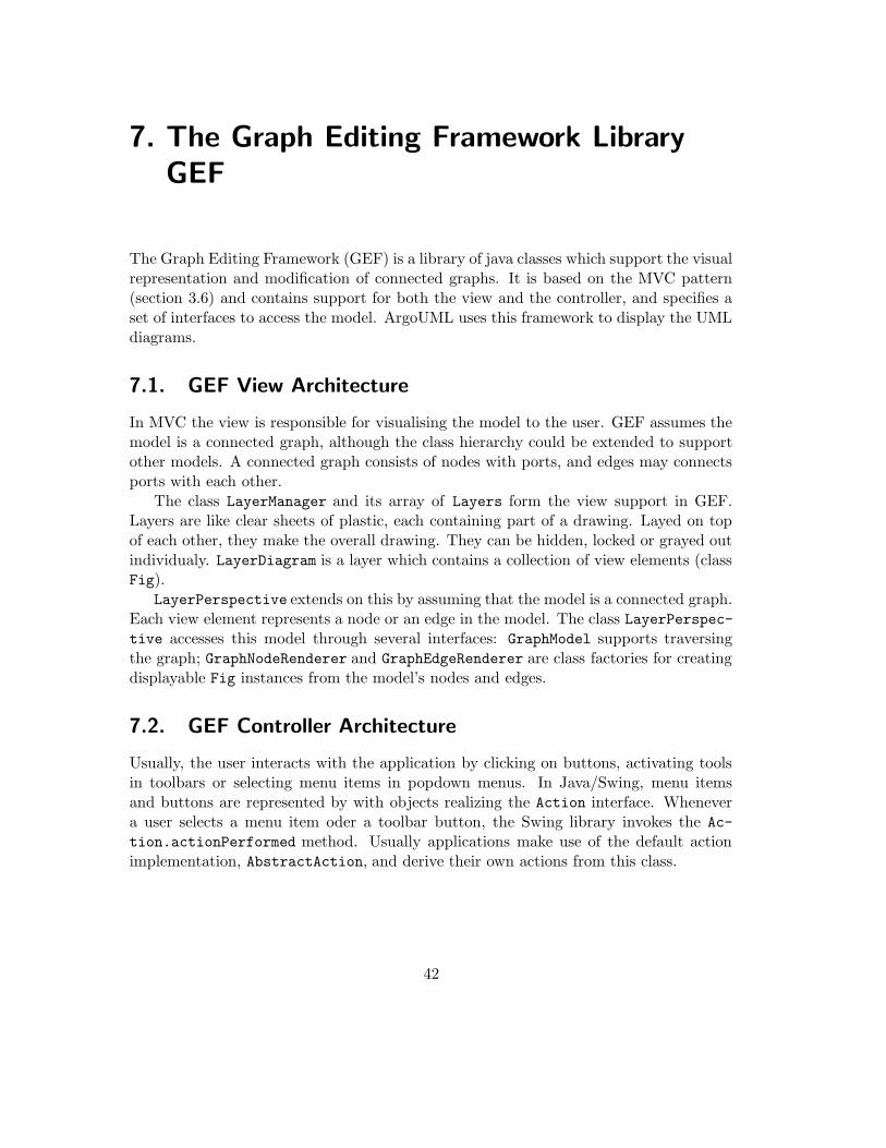
The Graph Editing Framework (GEF) is a library of java classes which support the visualrepresentation and modification of connected graphs. It is based on the MVC pattern(section 3.6) and contains support for both the view and the controller, and specifies aset of interfaces to access the model. ArgoUML uses this framework to display the UMLdiagrams.
7.1. GEF View Architecture
In MVC the view is responsible for visualising the model to the user. GEF assumes themodel is a connected graph, although the class hierarchy could be extended to supportother models. A connected graph consists of nodes with ports, and edges may connectsports with each other.
The class LayerManager and its array of Layers form the view support in GEF.Layers are like clear sheets of plastic, each containing part of a drawing. Layed on topof each other, they make the overall drawing. They can be hidden, locked or grayed outindividualy. LayerDiagram is a layer which contains a collection of view elements (classFig).
LayerPerspective extends on this by assuming that the model is a connected graph.Each view element represents a node or an edge in the model. The class LayerPerspec-tive accesses this model through several interfaces: GraphModel supports traversingthe graph; GraphNodeRenderer and GraphEdgeRenderer are class factories for creatingdisplayable Fig instances from the model’s nodes and edges.
7.2. GEF Controller Architecture
Usually, the user interacts with the application by clicking on buttons, activating toolsin toolbars or selecting menu items in popdown menus. In Java/Swing, menu itemsand buttons are represented by with objects realizing the Action interface. Whenevera user selects a menu item oder a toolbar button, the Swing library invokes the Ac-
tion.actionPerformed method. Usually applications make use of the default actionimplementation, AbstractAction, and derive their own actions from this class.
42

Node Edge
Port
Figure 7.1.: GEF assumes the model is a connected graph
1 1..*
org.tigris.gef.graph
org.tigris.gef.presentation
0..*
1
Fig
<<interface>>GraphEdgeRenderer
<<interface>>GraphNodeRenderer
<<interface>>GraphModel
<<interface>>MutableGraphModel
org.tigris.gef.base
LayerPerspectiveMutable
LayerPerspective
LayerDiagramLagerPageBreaksLayerGrid
Editor Layer{abstract}
LayerManager
Diagram
Figure 7.2.: GEF editor architecture
43

org.tigris.gef.base
javax.swing
AbstractAction{abstract}
<<interface>>Action
Cmd{abstract}
CmdSave CmdShowProperties CmdCreateNode CmdCopy
{incomplete}
Figure 7.3.: Partial Cmd class hierarchy
7.2.1. GEF command classes
The GEF class Cmd is an abstract superclass for all editor commands, adding commandarguments, support for “undo” and an application-global command registry. GEF con-tains over 40 Cmd subclasses, supplying support for load/save commands, cut and pastecommands and commands to add and delete nodes. An application can, of course, addnew Cmd-subclasses as required.
7.2.2. GEF Editing Modes
In order to support visual editing, the editor must keep track of which mode (or modes)it is in. How the editor reacts, for example, when the user clicks on the diagram dependson whether the user previously triggered CmdCreateNode to add a new figure to thediagram (ModePlace) or is selecting a figure in order to move it (ModeSelect followedby ModeModify). The class ModeManager keeps track of which modes are currentlyactive1. Whenever the editor receives an event (e.g. the user clicks on a figure) the topmode on the stack gets a chance to react to the event.
If the mode does not consume the event the next modes in the stack get a chanceto process the event, from top to bottom. This puts all behavior associated with aparticular mode into one object. Since all the behaviors are encapsulated in classesrealizing the FigModifyingMode interface, new application-specific behaviors can easilybe added.
Initialy, the ModeManager’s stack contains three modes: ModeDragScroll, ModeSe-lect and ModePopup. ModeDragScroll allows the user to scroll the editor by clicking
1Note that this architecture is based on the state pattern [Gamma+95], allowing an object (in thiscase, the editor) to alter its behavoir when its internal state changes.
44
Editor
1
ModeManager 1..∗{stack}
<<interface>>FigModifiyingMode
<<interface>>Mode
FigModifiyingModeImpl
ModeImpl
ModeBroom ModeCreate ModeDragScroll ModeModify
ModePlace ModeSelectModePopup
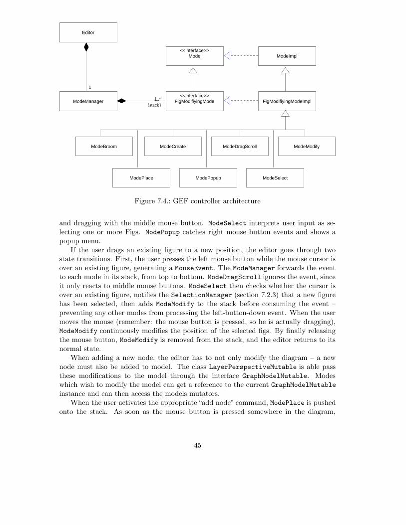
Figure 7.4.: GEF controller architecture
and dragging with the middle mouse button. ModeSelect interprets user input as se-lecting one or more Figs. ModePopup catches right mouse button events and shows apopup menu.
If the user drags an existing figure to a new position, the editor goes through twostate transitions. First, the user presses the left mouse button while the mouse cursor isover an existing figure, generating a MouseEvent. The ModeManager forwards the eventto each mode in its stack, from top to bottom. ModeDragScroll ignores the event, sinceit only reacts to middle mouse buttons. ModeSelect then checks whether the cursor isover an existing figure, notifies the SelectionManager (section 7.2.3) that a new figurehas been selected, then adds ModeModify to the stack before consuming the event –preventing any other modes from processing the left-button-down event. When the usermoves the mouse (remember: the mouse button is pressed, so he is actually dragging),ModeModify continuously modifies the position of the selected figs. By finally releasingthe mouse button, ModeModify is removed from the stack, and the editor returns to itsnormal state.
When adding a new node, the editor has to not only modify the diagram – a newnode must also be added to model. The class LayerPerspectiveMutable is able passthese modifications to the model through the interface GraphModelMutable. Modeswhich wish to modify the model can get a reference to the current GraphModelMutableinstance and can then access the models mutators.
When the user activates the appropriate “add node” command, ModePlace is pushedonto the stack. As soon as the mouse button is pressed somewhere in the diagram,
45

Waiting Modifying
ModeManager stack:
ModeDragScrollModeSelectModePopup
ModeManager stack:
ModeModify
ModePopupModeSelectModeDragScroll
mouse_lbutton_up / pop()
mouse_lbutton_down [cursor on a fig]/select_fig; push (ModeModify)
mouse_move/translate_selection
Figure 7.5.: Moving a figure to a new position
SelectionReshape
SelectionMoveSelectionLowerRight
SelectionResize
SelectionNoop
SelectionRotate
Selection{abstract}
SelectionManager selections
∗
<<interface>>SelectionListener
∗listeners
notifies
Figure 7.6.: GEF selection classes
ModePlace creates the respective Node instance as well as a corresponding Fig. Oncethe mouse button is released, the newly created node is added to the model by callingMutableGraphModel.addNode.
7.2.3. GEF Selection classes
The set of figures which are currently selected is handled by the SelectionManager.Whenever the selection changes, this class also notifies all registered SelectionListen-
ers (observer pattern, section 3.1) of the change. This could allow another window toupdate its contents to stay synchronized with the diagram. The SelectionManager alsoasks the figure whether it has a Selection object. This object contains the behavoir ofa figure in its selected state.
Selection objects handle the display of handles or whatever graphics indicate thatsomething is selected, and they process events to manipulate the selected figure. GEFoffers several Selection subclasses, which can be extended by the application.
46

SelectionMove allows the user to move the figure by dragging it, but not to resize it
SelectionNoop does not allow the user do manipulate the figure.
SelectionReshape draws one handle over each point in the figure. This allows the userto reshape the figure by moving the individual points.
SelectionResize shows the user the figure’s bounding box with handles allowing the userto resize the figure.
SelectionLowerRight is similar to the SelectionResize class, but only allows resizing bydragging the lower right corner of the boudning box.
SelectionRotate allows the user to rotate the figure.
7.3. Diagram Persistance
In addition to saving and restoring the underlying model (which does not fall under theresponsibility of GEF), an application will probably need to save and restore the diagrams– otherwise, the information about what model elements appear in which diagram (atwhat geometric coordinates) will be lost.
The GEF library currently (version 0.9.x) stores its diagrams as Precision GraphicalMarkup Language (PGML) documents. PGML is an XML application designed torespresent 2D scalable graphics. GEF’s graphic primitives are very similar to the PGMLelements with few exceptions:
text objects GEF defines a rectangle with left, right or centered text inside; PGMLdefines an origin and always writes the text left to right from that point.
groups of shapes GEF uses the FigGroup class to represent a group of shapes (com-posite pattern, section 3.5). The nodes in the graph model are represented bysubclasses of FigNode which subclasses from FigGroup. These subclasses couldbe more than simply groups of shapes, with their own behavior for resizing andcomputing text (should the text grow when the shape is expanded or should theline-breaks be recomputed?) PGML does not support this will simply scale thetext along with the shape.
Additionaly, every edge and node in a PGML document has a reference to the modelelement it represents.
The PGML documents are generated by the class OCLExpander. A TEE-document(Templates with Embedded Expressions) contains templates for all the java classes usedin the diagrams, and can contain an OCL-like expression2. The OCLExpander evaluatesthese expression using the current context of the java class being processed, so if theTEE document contains:
2only a very small subset of OCL expressions in the form self.attribute.attribute... are supported
47

OCLExpander PGMLDocument
TEE−File
GraphModel
Figure 7.7.: GEF generation of PGML files
<template class="org.tigris.gef.presentation.FigEdge">
classname="<ocl>self.class.name<ocl>"
</template>
then any FigEdge objects will be encoded as:
classname="org.tigris.gef.presentation.FigEdge"
in the output document.The next major version of GEF will replace PGML with SVG (Scalable Vector Graph-
ics), another XML application, but the template-based approach will probably remain.
48

8. ArgoUML Architecture
The ArgoUML application consists of three main packages (each containing many sub-packages): the Novosoft UML metamodel library (NSUML), the Graph Editing Frame-work (GEF), and of course, ArgoUML itself. NSUML contains all the classes neededto represent and manipulate UML 1.3 models, GEF is responsible for visualising theseUML models as diagrams, and ArgoUML ties all this together and adds the applicationlogic.
The Model-View-Controller architecture is essential for any UML modelling tool.Each project usually contains exactly one UML (user level) model, but contains manyviews on the model. The various UML diagrams, the form-based property panels, eventhe navigator pane (which shows the model in a tree-like structure) are all simply differentviews which visualize the model from different perspectives and in different ways.
In figure 8.2, it should be clear that all three views are views on the same UML model.’P2’ in each diagram represent the same model element, namely the UML package P2.
Figure 8.3 shows the layout of the ArgoUML user interface, which consists of severalpanels. The navigator pane displays the project in one of several perspectives as atree-like structure, enabling easy navigation. The multieditor pane is the main paneof the application containing a diagram-specific toolbar, and of course, the GEF editorpane displaying the active UML diagram. The details pane shows the attributes of thecurrently selected model element. The todo pane displays a list design issues which needthe user’s attention. The application menu bar and status bar perform the obvious tasks.
The main ArgoUML window is the singelton1 ProjectBrowser, containing classesfor each of the windows panes.
8.1. The UML Diagrams
ArgoUML uses the GEF library for the various UML diagram types. As detailed insection 7.1, GEF assumes that the data it visualizes is structured as a graph consistingof nodes and edges.
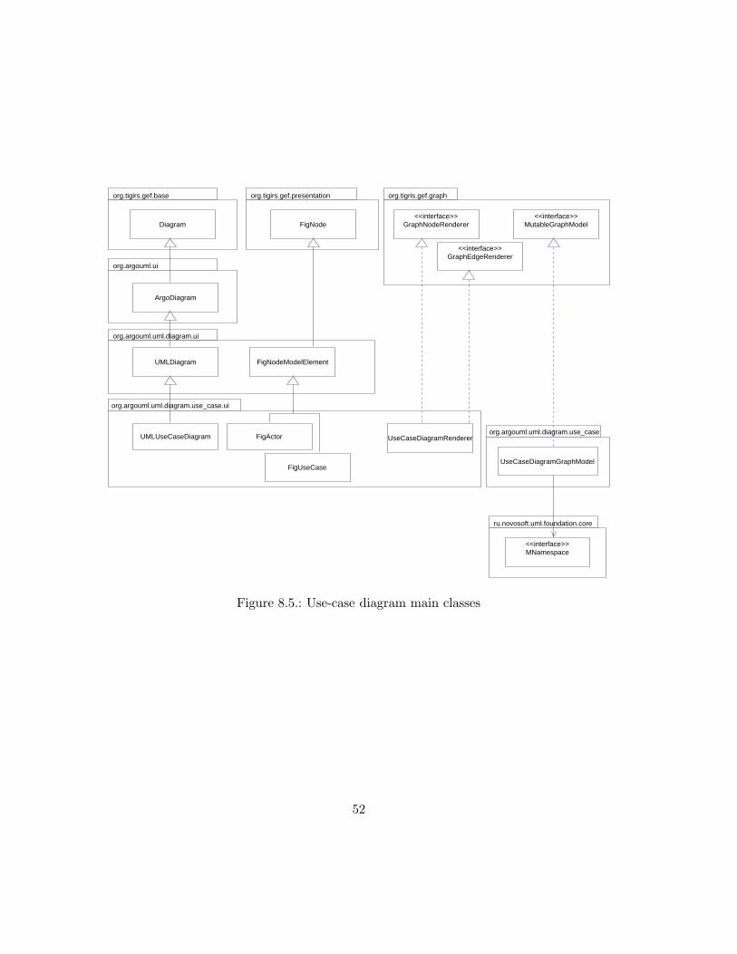
GEF uses the GraphModel interface to access the model. The ArgoUML classeswhich implement this interface must map the UML metamodel to GEF’s node-and-edgestructure. In this section, the UML use-case diagram (one of the simpler diagrams) willserve as an example to illustrate the ArgoUML diagram design.
1the singelton pattern [Gamma+95] is not used here, so it would be possible to create additionalinstances, although this is not recommended
49

org.argouml
org.tigis.gef
javax.swing
ru.novosoft.uml
Figure 8.1.: high-level view of the ArgoUML architecture
P2
C1
P1
P2
P1
P2
C1
Figure 8.2.: Three views of the same model
MultiEditor Pane
Status Bar
Navigator Pane
Menu Bar
ToDo Pane
Details Pane
Figure 8.3.: ArgoUML user interface
50

org.tigris.gef.baseorg.argouml.ui
1Editor
<<singelton>>ProjectBrowser MultiEditorPane
DetailsPane
NavigatorPane
StatusBar
ToDoPane1
1
1
1
1
Figure 8.4.: Major ArgoUML user interface classes
UML metaclass figure class graph element
MActor FigActor node
MUseCase FigUseCase node
MGeneralization FigGeneralization edge
MDependency FigDependency edge
Table 8.1.: UML use-case diagram figures and model elements
A use-case diagram can contain the following model elements: actors, use-cases,dependencies and generalizations. The UseCaseDiagramGraphModel must map thesemetaclasses to GEF figure classes.
As shown in table 8.1, actors and use-cases are considered nodes, since they canexists independently. Generalizations and dependencies are edges which connect thenodes. These figure classes represent the metaclasses graphically in a specific diagram.
Implementing the various UML diagrams (static structure, use-case, sequence, etc.)is suprisingly straightforward. Due to the supporting framework, only a few classes foreach diagram type are necessary. Each UML diagram type requires:
1. a class derived from Diagram. This class should contain member objects for eachcommand (usually Cmd-Subclasses, section 7.2) the user may trigger. ArgoUMLsupplies the classes ArgoDiagram which uses the observer pattern (section 3.1) toadd listener registration support allowing the diagram to react to changes in themodel, as well as the class UMLDiagram which adds support for a UML model (in-terface MNamespace as opposed to the generic MutableGraphModel) and commandscommon to all UML diagrams.
2. a displayable Fig subclass for each UML metamodel element which can be insertedin the diagram.
3. a factory class (section 3.4) realizing the GraphEdgeRenderer and GraphNodeRen-
derer interfaces which can create the necessary Fig instances on demand.
51
org.tigirs.gef.base
Diagram
org.tigris.gef.graphorg.tigirs.gef.presentation
FigNode<<interface>>
GraphNodeRenderer
<<interface>>GraphEdgeRenderer
<<interface>>MutableGraphModel
ru.novosoft.uml.foundation.core
<<interface>>MNamespace
org.argouml.uml.diagram.use_case
UseCaseDiagramGraphModel
org.argouml.uml.diagram.use_case.ui
UMLUseCaseDiagram FigActor
FigUseCase
UseCaseDiagramRenderer
org.argouml.uml.diagram.ui
UMLDiagram FigNodeModelElement
org.argouml.ui
ArgoDiagram
Figure 8.5.: Use-case diagram main classes
52

TabToDo TabDocumentation TabSrc
TabConstraints
TabTaggedValues
TabChecklist
DetailsPane
JPanel(from javax.swing)
TabProps{abstract}
TabStyle
PropPanelModelElement{abstract}
PropPanelDiagram{abstract}
PropPanel{abstract}
Figure 8.6.: ArgoUML details pane classes
4. a adapter class (section 3.2) realizing MutableGraphModel allowing GEF to accessand modify the UML model.
Support for each type of UML diagram is encapsulated in its own subpackage hierarchy.
8.2. The Details Pane
The details pane is below on multieditor pane. It consists of several tabs, each of whichshows details about the currently selected object. This object can be an element in theuser’s model, a diagram or a figure. This allows the user to inspect and edit the object’sattributes in a form-based manner.
ToDo Tab is used by the todo pane to show details about the selected todo item
Properties Tab shows the attibutes and references of the currently selected model el-ement. Its contents is dependent on the metaclass of the element – a class hasdifferent attribues than an actor. These different contents are encapsulated insubclasses of PropPanel.
Documentation Tab allows the user to add textual documentation to individual modelelements. These text strings stored as tagged values in the model.
53

Style Tab allows the user to change appearance of the figures in the diagram. Thisdoes not change the model in any way, only the visual representation of the modelelements.
Source Tab lets the user enter implementation details directly into the model.
Constraint Tab displays the constraints linked to the selected model element.
Tagged Values Tab shows the tagged values of the selected element.
CheckList Tab is used by the cognitive support package.
8.3. The Navigator Pane
The navigator pane is shown to the left of the editor pane. It shows the user’s modelin a tree-like diagram. It is based on the swing class JTree, which requires a classimplementing TreeModel from which it gets the tree’s data.
Since the user’s model is a graph and not necessarily a tree, there are many ways(perspectives) to represent the model in a tree-like structure. One possibility is to startwith the model, branch into the namespaces and packages (and subpackages), branchingfurther into the individual classes and finally to the class attributes and operations (whichare leaves in the tree). This perspective is named ‘package-centric’ and is one instance ofNavPerspective. Another instance is the ’diagram-centric’ perspective, where the rootof the tree is the project, which branches into the various diagrams, which branch intothe diagram’s figures.
The only real difference between the perspectives are the parent-to-child branchingrules. In the above example, the package-centric perspective has the rules ’package-to-subpackage’, ’package-to-class’, ’class-to-attribute’, etc. These rules are implementedin GoParentToChild classes realizing the TreeModelPrereqs interface. All the rulesknown to the system are registered in the static vector NavPerspective.rules.
One interesting class is the GoFilteredChildren class. It does not implement a ruleitself, but is used with another rule, filtering out any children not of a specific type. AGoFilteredChildren instance configured to filter out anything but stereotypes, togetherwith GoModelToElements (which returns all owned elements of a namespace) would makea ’namespace-to-stereotype’ rule.
Each NavPerspective instance serves as the TreeModel for the UI JTree component.Through the use of the composite pattern (section 3.5) each NavPerspective instanceconsists of subtrees, which can be either instances implementing the branching rules orother perspectives. This offers a very flexible system for constructing new perspectives.ArgoUML even allows the user to create new perspectives at run time by combining thevarious rules.
54

<<interface>>TreeModel
(from javax.swing.tree)
TreeModelComposite
<<interface>>TreeModelPrereqs NavPerspective
JTree(from javax.swing.tree)
DisplayTextTree NavigatorPane
GoFilteredChildren GoModelToElements
GoModelToClass GoClassifierToBeh
subTreeModels
∗
∗
∗∗rules
tree1
1
∗
1
renders
{incomplete}
filters
Figure 8.7.: ArgoUML navigator pane classes
55

org.argouml.cognitive
<<singelton>>Designer
ToDoList
critics
<<singelton>>Agency
Critic
CompoundCritic
(from org.argouml.uml.cognitive.critics)CrUML
informs
1
1
manages
*
#critics
*
Figure 8.8.: Design critics major classes
8.4. The Design Critics
The design critics are part of ArgoUML’s cognitive support package which aids thedeveloper in making and documenting the design decisions.
The Designer singelton (section 3.3) constantly observes the user’s model. In abackground thread, it uses the Agency to analyse the model’s structure. SpecializedCritic instances check the user’s model for common design errors (for example, anillegal class name or a state without transitions). Through the use of the compositepattern (section 3.5), complex critics can be constructed from simple critics.
If a concrete Critic discovers an problem in the model, the Designer adds a itemto the ToDoList, which appears in the todo panel. It is then up to the user to decidewhether this issue should be considered or ignored. A critic can also offer a wizard toaid the user in handling the isssue. A wizard could, for example, immediatly show theoffending model element in the properties panel.
56

org.tigris.gef.baseorg.argouml.ui
<<singelton>>ProjectBrowser ArgoDiagram Diagram
_models
1..*1
*
org.argouml.kernel
Project
ru.novosoft.uml.foundation.core
<<interface>>MNamespace
Figure 8.9.: The class Project contains the models and the diagrams
8.5. The ArgoUML project
All of the uml diagrams and models in a project are contained in a single Project
instance2. This class is also responsible for loading and saving diagrams and models.An Argo Project consists of many members, each of which has its own requirements
for persistance. The UML model, the diagrams, and information about the project itselfmust all be saved to a file and, of course, be restored again whenever the user reopensthe project. Since both GEF and NSUML can save and restore XML documents, Argoonly has to invoke the appropriate methods.
The abstract class ProjectMember forms an interface between Argo and the individ-ual member. The concrete classes ProjectMemberDiagram and ProjectMemberModel
override the save and load methods and call the approriate GEF and NSUML meth-ods.
The ActionSaveProject.trySave method (package org.argouml.ui) is invokedwhenever the user click on the appropriate button or selects the ‘Save Project’ menuitem. This method first saves the project information in an argo-specific XML doc-ument. This is done in the same way GEF creates its XML documents: a templatefile (argo.tee) specifies which member variables of the project are to be saved. Uponcompletion, every ProjectMember gets a chance to save its information:
• The ProjectMemberModel.save method creates an XMIWriter instance and gen-erates an XMI document as detailed in section 6.10.
• The ProjectMemberDiagram.save method creates an OCLExpander instance andgenerates a PGML document as detailed in section 7.3.
2ArgoUML has exactly one open project - although the architecture could easily support many simul-taneously opened projects
57

In order to avoid having several, semantically bound documents as separate files, Argopacks them all together into a standard ZIP-file with the extension zargo.
Restoring the state of a project from the XML documents is similar. An XMIReader
is responsible for recreating the model, and OCLExpander instances recreate the projectstatus and the diagrams.
58

Part III.
The CCL Modelling Tool
59

9. Extending the ArgoUML Modelling Tool
The main goal of this work is to create a design for the CCL modelling tool by extend-ing ArgoUML to support the concepts and methods introduced in [Bubl2001-CoCons].The first task was to decide on a general strategy on how to extend ArgoUML whilekeeping the impact on the ArgoUML sources as small as possible. The resulting pluginmechanism is detailed in section 9.1.
The new concepts require a UML 1.3 metamodel with a subset of the UML 1.4 spec-ification in addition to the CoCon metamodel. Since ArgoUML uses the Novosoft UML1.3 java implementation library, it is necessary to extend this library to incorporate thenew metamodel. The design of the metamodel extension library is detailed in chapter 10,which lays the foundation for the CoCons modeling tool.
A high-level view of the package structure is shown in figure 9.1. Brief descriptionsof the package responsibilities follow:
org.cocons.uml contains the java implementation of the CoCons metamodel. The classesimplementing model persistance are in the xmi subpackage.
org.cocons.argo contains the extension to the ArgoUML editor.
org.cocons.argo.plugin contains the classes necessary to support the plugin mechanism.
org.cocons.argo.ui contains the user interface components for the new concepts intro-duced in the CoCons metamodel. This include the property panels which allowthe user to edit the model in a dialog-box manner, instead of visually.
org.cocons.argo.cognitve contains the design critics classes which inform the user whenthe design does not conform to certain semantic rules. One example is a designcritic which tests whether the model conforms to all context-based constraints.
org.cocons.argo.diagram contains the classes which implement the new CCL diagramtypes. This package (and the subpackages) rely heavily on the GEF library.
9.1. Adding a Plugin Mechanism
ArgoUML is not a finished product and its development is advancing at a rapid pace.This poses an interesting challenge for the CCL extensions: since these extensions arenot yet ready for production use it is unlikely that they will be incorporated into themain ArgoUML source trunk. Until this time, a parallel branch will exist. Each time
60

org.argouml
org.tigris.gef
org.cocons.argo
ui plugin
cognitive diagram
ru.novosoft.uml
org.cocons.uml
ccl xmi
Figure 9.1.: The CoCons modeling tool architecture
61

CCL extensions
merge
merge
merge
ArgoUML(trunk)
branch
Figure 9.2.: Branching and merging the sources
the ArgoUML sources are changed, these changes will have to be merged with the CCLbranch in order to profit from any enhancements. Any ArgoUML files which have beenmodified in the trunk (by the Argo developers) as well as in the branch (by the CCLdevelopers) may cause merge conflicts, which have to be resolved manually. Dependingon the number of files which have CCL specific modifications, the merge procedure couldbecome quite tedious. Once the CCL extensions are ready for production use, they wouldhave to be incorporated back into the main trunk, resulting in yet another merge.
Even then, the system (i.e. ArgoUML and the CCL extension) will continue to evolvedue to changes in the environment: newer versions of the unified modeling language willhave to be supported, new technologies will appear, etc. It should be possible to modifiythe system in such a way that a consistent system state is achieved while satisfying anynew requirements. As described in [Große-Rhode+2000], the decompostion of a systeminto components can increase the adaptability of the system by limiting dependencies.By separating the system into an ArgoUML-component and a CCL-component, the firststep is taken to avoid the two of dependencies that can occur: source dependency anddistribution dependency.
9.2. Avoiding source dependency
Source dependency occurs when one package is imported into another package. If aclass in the first package is modified, all dependent packages must be rebuilt. Sourcedependency can be avoided by ensuring that no ArgoUML package imports any CCLpackages – even though ArgoUML must be able to (directly or indirectly) access theCCL classes.
Through the use of java interfaces we can prevent ArgoUML from being dependenton the CCL packages (figure 9.3). The class ProjectBrowser can invoke methods ofCCLPlugin through the ArgoPlugin interface. Implementation details of the CCL ex-tension remain unknown to ArgoUML and ArgoUML is not dependent on the CCLpackage. In this way, ArgoUML can be developed regardless of the extension – reducing
62

org.argouml
0..∗
applicationutil.plugin
<<interface>>ArgoPlugin
org.cocons.argo.plugin
CCLPlugin
Main
Figure 9.3.: Using interfaces to avoid source dependency
the cost of merges considerably.
9.3. Avoiding distribution dependency
In order to keep ArgoUML distribution independent, the CCL-specific modificationsshould be implemented as independently distributable plugins. A generic plugin mech-anism is an important step in isolating the CCL extensions from the ArgoUML dis-tributables. Such a mechanism would allow the development of ArgoUML extensionsrequiring no further modification of ArgoUML classes. Ideally, the plugins would bedistributed as java archives (.jar) and would simply be copied into a plugin directory.They could be developed, deployed, updated or removed independently from ArgoUMLwithout having to reinstall or recompile ArgoUML itself. The user would be able toinstall plugins without having access to the source of ArgoUML or the extension.
This can be achieved through the use of java’s dynamic extension[Venners99]. Java’sarchitecture allows applications to dynamically extend themselves by loading and us-ing classes at runtime – even if the classes did not yet exist when the application wascompiled. The simplest way to load classes at runtime is with the static method for-
Name(String className) from java.lang.Class. The forName method searches theCLASSPATH for the .class file and loads the class dynamically. This class can then beinstantiated with newInstance():
63

ArgoUML
Argo−PluginCCL Extension
<<uses>>
<<depends>>
Figure 9.4.: Using interfaces to avoid distribution dependency
Class c = Class.forName("DynamicClass");
MyInterface i = (MyInterface) c.newInstance();
i.init();
This code dynamically loads the class DynamicClass, creates an instance and calls themethod init(). The class DynamicClass may not even have existed when this code waswritten and compiled – as long as it implements the interface MyInterface. Unfortu-nately, this is not enough to meet the requested requirements: the necessity of havingto set the CLASSPATH to include each plugin prohibits easy installation.
A more flexible way of dynamically loading classes is by writing a custom class loader.Java has two kinds of class loaders – the primordial class loader build into the JVM whichnormally loads all classes and interfaces used by an application, and custom class loaders(also called class loader objects). A custom class loader is not restricted to searching thecurrent CLASSPATH – it can be constructed to load classes from any source: a file, anarchive or even a HTTP stream.
Each java archive plugin is represented by an instance of PluginJarFile. Each in-stance contains a custom class loader able to load the plugin’s classes on demand fromthe .jar file. Archive files are great for distribution, but having to construct a .jar fileand copy it into the plugin directory after every make cycle would complicate the de-velopment process. During development the plugin consists of many .class files. Forthis reason, an alternative loading mechanism is available. Instances of PluginClass-
File (also implementing the PluginSource interface) each represent a plugin and all ofits .class files. The contained FileClassLoader is responsible for dynamically loadingthese .class files. The PluginManager acts as a facade hiding all the details of the pluginmechanism. During construction it builds a collection of all plugins – each representedby an object supporting the PluginSource interface. Once creation is completed, theapplication can request a collection of all plugins by calling getPluginFiles().
In order to actually load the plugin classes, the application must iterate throughthis collection and call PluginSource.loadClass(). The returned classes may then beinstantiated.
64

org.argouml.util.plugin
JarClassLoader
(from java.util)ClassLoader
{abstract}
FileClassLoader
PluginJarFilePluginClassFile
<<interface>>PluginSourcePluginManager ∗
1 1
Figure 9.5.: The plugin mechanism custom class loaders
:Application
:PluginManager
:PluginJarFile
:PluginClassFile
new
* new
scanForJarPlugins()
getPlugins
scanForClassPlugins()
* new
Figure 9.6.: The PluginManager finds the plugin sources
65

Vector pluginSources = pluginManager.getPlugins();
Iterator i = classnames.iterator();
while (i.hasNext())
{
PluginSource pluginSource = (PluginSource) i.next();
Class c = pluginSource.loadClass();
ArgoPlugin i = (ArgoPlugin) c.newInstance();
i.init();
}
Exactly what then happens to these instances is up to the application. The plugin mech-anism makes no assumptions about the classes to be loaded – although the applicationitself will require a specific interface. (ArgoPlugin in the above example).
9.4. Plugin dependencies
With this architecture, the application is no longer dependent on the plugin, and theplugin’s interface is well specified. However, the plugin is heavily dependent on theapplication. Once the plugin is initialized by the application, it uses whatever classesand data structures of the application it needs. If the application is ever changed in afundamental way, it will likely ’break’ any existing plugins.
The next step would therefore be to minimize the plugin’s dependency on the appli-cation by defining a set of interfaces plugins may use1. As ArgoUML evolves, backward-compatible versions of these interfaces should remain available in order to support olderplugins. This would make the application, as well as the plugins, replaceable in regardto the system as a whole.
9.5. Limits
Since version 0.93 ArgoUML is deployable by Java Web Start. When using this loadingmechanism, the application’s distributables are stored on a central http-server. Whenthe application is executed by a client, the distrubutables are downloaded on demandto a client-side cache, where they are then executed. The advantage: no client-sideinstallation of the application is necessary.
The plugin architecture does not account for this variant – although it could beextended to support Web Start. The main issue is where to install the plugins. If theuser is to have control over the plugins, then a client-side plugin directory would benecessary. Additionally, ArgoUML would have to know the location of this directory(perhaps specified by an environment variable). Client-side installation (of the plugins)is then required – which defeats the very purpose of Web Start. A second alternativewould be server-side plugins. A new class implementing PluginSource, analog to thePluginJarFile class, but able to load classes from a http server would be required. Theapplication’s administrator (not the user) would decide which plugins are to be madeavailable to the users.
1as this work was nearing completion, the Argo community started developing a set of plugin-APIs.
66

10. The CoCons Physical and ObjectModels
The CoCons physical model relates to the CoCons metamodel [Bubl2001-CoCons, section3] in the same way the UML physical model relates to the UML metamodel. Thereare fewer changes necessary than with the UML models, since the CoCons metamodelcontains no association classes:
• unnamed association ends are named
• all assocations are bidirectionally navigatable
• metaattributes changed to start with a lowercase letter
• rolenames changed to start with a lowercase letter
• packages names changed to contain only lowercase letters
The CoCons CCL object model contains the changes necessary to implement the CoConsphysical model in Java. The following requirements should be met:
1. The CoCons CCL object model should fully implement the CoCons physical model
2. The CoCons CCL object model should follow the syntatic and semantic conventionsof the NSUML object model
3. All features offered by the NSUML classes should also be offered by the CCL classes(undo/redo, persistance, etc.)
10.1. Extending the NSML Library
The ConCons metamodel extends the UML 1.4 metamodel. Unfortunatly, at the timeof this writing, NSUML only implements the UML 1.3 object model. Future versions ofthe Novosoft libraries will support automatic generation of of an object model from anabstract metamodel specification (NSGEN and NSMDF libraries). This will open newpossibilites for modelling tools. It will then be possible to simply modify the metamodelspecification and re-generate the java library.
Until ArgoUML supports these NSGEN and NSMDF releases, the NSUML librarymust be extended to include the modifications introduced in the UML 1.4 specification.
67

dataValue : String[*]
(from Extension Mechanisms)
TaggedValue
ModelElement
icon : GeometrybaseClass : Name[*]
(from Extension Mechanisms)
Stereotype
Constraint(from Core)
body: BooleanExpression
ContextCondition
query : BooleanExpressionrange: MultiplicitybaseClass: Name
ContextbasedConstraint
tagType : Namemultiplicity : Multiplicity
TagDefinition(from Extension Mechanisms)
ContextPropertyTag
(from Relationships)Attribute
1
+referenceValue
+referenceTag*+taggedValue*
+typedValue *
{ordered} *
*
+constrainedElement +modelElement
(from Core)
0..1+owner0..1
1 +valueValidation
+stereotypeConstraint
* +constraint
*
+restrictedStereotype*
*
+scopeElement
0..1+scopeSet
+scopedConstraint 0..1 0..1
0..1 +constrainedSet
+contextBasedConstraint
+restriction
*
+constrainedStereotype
+scope*
+type
1+definedTag
*
*
+contextPropertyTag
+contextBasedConstraint
0..1 *
+detail
Figure 10.1.: CoCons physical model
68

Since CoCons only relies on a few UML metaclasses, supporting the following subset ofthe UML 1.4 specification is sufficient:
1. multiplicity of ModelElement end of association modelElement (ModelElement)
/ taggedValue (TaggedValue) changed from 0..1 to 1
2. association referenceValue (ModelElement) / referenceTag (TaggedValue)
added
3. TaggedValue attribute value replaced with dataValue – datatype changed fromString to String[*]
4. TaggedValue is now derived from ModelElement – attribute name now inheritedfrom ModelElement
5. datatype of Stereotype attribute baseClass changed from Name to Name[*]
6. multiplicity of ModelElement end of association constrainedElement (ModelEle-
ment) / constaint (Constraint) changed from 1..* to *
7. unnamed association role (Stereotype) / stereotypeConstraint (Constraint)
now named constrainedStereotype(Stereotype) / stereotypeConstraint(Con-straint) 1
8. association requiredTag (TaggedValue) / stereotype (Stereotype) removed
9. metaclass TagDefinition added as subclass of ModelElement
10. association typedValue (TaggedValue) / type (TagDefinition) added
11. association owner (Stereotype) / definedTag (TagDefinition) added
This can be achieved in two ways:
1. By subclassing the necessary NSUML classes and interfaces. A new UML 1.4 class(e.g. CStereotypeImpl)would be derived from the UML 1.3 class (MStereotypeImpl)and override the appropriate methods. Modifying the MFactory class factory (sec-tion 3.4) would then ensure that only the new classes are instantiated. This wouldavoid having to modify any of the NSUML source files, avoiding the brach/mergeproblems described in section 9.1. Problems could occur if ArgoUML instantiatesthe UML 1.3 classes directly without using factory methods.
2. By directly modifying the NSUML sources. There would be no obsolete classes,avoiding the above problem – at the cost of the branch/merge problem.
1in the physical model the role was named constrainedElement2 in UML1.3
69

An analysis of the sources reveals that ArgoUML does not make extensive use of the classfactory – the UML 1.3 classes are instantiated directly. The modifications necessary tomake all ArgoUML sources use the class factory would far outweigh simply modifyingthe NSUML sources. Additionaly, the current version of NSUML (version 0.4.19) seemsto be quite stable – until the next release of the NSGEN/NSMDF packages. Both ofthese reasons favor the second alternative – modification of the NSUML sources:
Modification 1 Since the java object model does not differentiate between the multi-plicities 0..1 and 1 (section 6.6), no modification is necessary
Modification 2 Appropriate bag role (section 6.6) members must be added to MMod-
elElement and MTaggedValue
Modification 3 This array-of-strings datatype did not exists in UML 1.3. In order tosupport this in a way consistent to NSUML, it should be implemented as a Collec-
tion with the appropriate getDataValues, setDataValues, addDataValue andremoveDataValue methods.
Modification 4 The MTaggedValue interface and MTaggedValueImpl class must be changedto be derived from MModelElement and MModelElementImpl. The obsolete in-spector and mutator methods for the UML 1.3 fields tag and value should beimplemented to throw a NoSuchMethodError.
Modification 5 Analog to modification (3): the appropriate getBaseClasses, setBase-Classes, addBaseClass and removeBaseClass methods must be added.
Modification 6 Analog to modification (1): no changes to the list role are necessary.
Modification 7 The *constrainedElement2-members should be renamed to *constrained-Stereotype.
Modification 8 The appropriate bag role methods should be added to MConstraint.
Modification 9 The bag role methods for this association should be removed from bothclasses.
Modification 10 The interface MTagDefintion and implementation class MTagDefinitionImplshould be added (derived from MModelElement and MModelElementImpl, respec-tivly)
Modification 11 The appropriate bag role members should be added to MTagDefinitionand reference role members to MTaggedValue.
Modification 12 The appropriate bag role members should be added to MStereotype
and reference role members to MTagDefinition.
70
In addition to the above modifications, the XMI support classes must also be modifiedto support the new metamodel.
With these modifications, the UML library is effectivly extended to support UML1.4 (at least the subset required by the CoCons metamodel), which can then serve asa foundation for the ConCons CCL object model. If and when NSUML supports UML1.4, these modifications will not longer be necessary and it should take little effort tomodify the CoCons CCL library to use the future NSUML 1.4 classes directly.
10.2. The CoCons CCL Java Library
The CoCons CCL Java library is a direct java implementation of the CoCons CCL objectmodel. In order to be consistent with the NSUML object model, the same conventionsare used:
• Each metaclass is implemented as a java class. Analog to the NSUML namingconvention, the class shoud be named after the metaclass, prefixed with the letter“M” and suffixed by “Impl” (e.g. MContextConditionImpl).
• Each metaclass has an interface specifying the inspector and mutator methods.The interface should be named after the metaclass, prefixed with the letter “M”(e.g. MContextCondition) – the java objects should always be referenced by theirinterfaces – never directly.
• Attributes should never be declared public – the appropriate getAttribute /setAttribute methods must be defined for each attribute.
• Associations must always be implemented in the classes at both ends. Dependingon the multiplicity the role, different inspector and mutator methods are specified:
– reference roles (multiplicity 0..1 or 1) define setRole (OppositeRole) andgetRole() methods
– bag roles (unordered multiplicity other than 0..1 or 1) define setRoles (Col-
lection), getRoles(), addRole (OppositeRole) and removeRole (Oppo-
siteRole) methods
– list roles (ordered multiplicity other than 0..1 or 1) define addRole (int,
OppositeRole), removeRole (int), setRole (int, OppositeRole) andgetRole (int) methods to allow accessing the roles at specific positions inthe list, in addition to the methods defined by bag roles.
• Regardless of the multiplicity, internalRefRole and internalUnrefRole meth-ods must be implemented for each role. These methods must be called by theassociation mutator methods at the opposite end to ensure the state of an associ-ation remains consistent at both ends.
71

• Every class must override the appropriate reflective* methods to allow settingand getting the attributes and roles.
• To support event notification, all mutator methods must begin with an call tooperationStarted() and end with operationFinished(). Whenever the stateis changed, the appropriate fire* method must be called, generating an event.
• To support undo/redo functionality each state change must be logged with theappropriate compensation operation. The necessary compensation methods shouldbe stored as private static member variables:
– attributes specifiy _attribute_setMethod method objects.
– reference roles specify _role_setMethod method objects.
– bag roles specify _role_setMethod, _role_addMethod and _role_removeMethod
method objects.
– list roles specify _role_listSetMethod, in addition to the method objectsspecified by bag roles.
• Every class must be derived from MBaseImpl or one of its subclasses (e.g. MMod-elElementImpl), every interface must be derived from MBase or one of its sub-classes.
• Every instance must have exactly one container2. Subclasses of MModelElement
are already contained by their namespace. If an class can be contained throughanother association (e.g. MConstraint can be contained either by its namespaceor by its stereotype), then the set* and internalRefBy* methods must also callMBase.setElementContainer.
10.3. CoCons Model Persistance
According to the XMI specification, it should be possible to create an XML documentspecifying the metamodel according to the MOF-DTD. With the appropriate tools, aCCL-DTD could then be automatically generated from this MOF document. Sadly, thereis a lack of freely available tools which support this. For this reason, the UML-DTDmust be extended manually to include the new metaclasses and associations of the CCLobject model. This extended DTD (‘CCL10.DTD’), located in the org.cocons.uml.cclpackage, can then be used to validate CCL-XMI documents containing CCL user models.
10.3.1. Extending the UML-Document Type Definition
In the UML-DTD, each metaclass is represented by its own XML-element. This elementcontains subelements for each of its attributes and roles. Additionally, every XML-element representing a metamodel class must define the XML-attributes %XMI.element.att
2the top-level namespace (or model) is the exception to this rule
72

and %XMI.link.att. These XML-attributes are used for resolving references when restor-ing the model from an XMI document.
<!ELEMENT CoCons.Uml.Ccl.ContextCondition (
CoCons.Uml.Ccl.ContextCondition.query?,
CoCons.Uml.Ccl.ContextCondition.range?,
XMI.extension*,
CoCons.Uml.Ccl.ContextCondition.contextPropertyValue*,
CoCons.Uml.Ccl.ContextCondition.restrictedStereotype*,
CoCons.Uml.Ccl.ContextCondition.scopedConstraint?,
CoCons.Uml.Ccl.ContextCondition.contextBasedConstraint?
)?>
<!ATTLIST CoCons.Uml.Ccl.ContextbasedConstraint
%XMI.element.att;
%XMI.link.att;
>
The element ‘XMI.extension’ is a predefined XML-element which is used by some ap-plications to store data in the XMI document which is out of the scope of the XMIspecification. It is should be placed between the attributes and the roles.
The subelements used in the above definition must also be defined:
<!ELEMENT CoCons.Uml.Ccl.ContextCondition.query
(Foundation.Data_Types.BooleanExpression)
>
<!ELEMENT CoCons.Uml.Ccl.ContextCondition.range
(Foundation.Data_Types.Multiplicity)
>
<!ELEMENT CoCons.Uml.Ccl.ContextCondition.contextPropertyValue
(Foundation.Extension_Mechanisms.TaggedValue)
>
...
Note the definition of contextPropertyValue: it contains the element TaggedValue
– this is how references are encoded in XMI. If the referered element has subclasses,they too must be listed in the reference. For example, the role feature of a Classi-
fier refers to the metaclass Feature. It has the subclasses StructuralFeature andBehavioralFeature, which have the subclasses Attribute, Operation and Method andReception. This means that a feature could refer to any of these subclasses. Thereforethe XML-element representing the role is defined as:
<!ELEMENT Foundation.Core.Classifier.feature
(Foundation.Core.Feature |
Foundation.Core.BehavioralFeature |
Behavioral_Elements.Common_Behavior.Reception |
Foundation.Core.Operation |
Foundation.Core.Method |
Foundation.Core.StructuralFeature |
Foundation.Core.Attribute
)* >
73

If the new metaclass is subclass of an existing class, then all the inherited attributes androles must also be included in the XMI-element definition:
<!ELEMENT CoCons.Uml.Ccl.ContextbasedConstraint
(Foundation.Core.ModelElement.name?,
Foundation.Core.ModelElement.visibility?,
Foundation.Core.ModelElement.isSpecification?,
Foundation.Core.Constraint.body?,
CoCons.Uml.Ccl.ContextbasedConstraint.priority?,
XMI.extension*,
Foundation.Core.ModelElement.namespace?,
Foundation.Core.ModelElement.clientDependency*,
Foundation.Core.ModelElement.constraint*,
Foundation.Core.ModelElement.supplierDependency*,
Foundation.Core.ModelElement.presentation*,
Foundation.Core.ModelElement.targetFlow*,
Foundation.Core.ModelElement.sourceFlow*,
Foundation.Core.ModelElement.templateParameter3*,
Foundation.Core.ModelElement.binding*,
Foundation.Core.ModelElement.comment*,
Foundation.Core.ModelElement.elementResidence*,
Foundation.Core.ModelElement.templateParameter2*,
Foundation.Core.ModelElement.stereotype*,
Foundation.Core.ModelElement.behavior*,
Foundation.Core.ModelElement.classifierRole*,
Foundation.Core.ModelElement.collaboration*,
Foundation.Core.ModelElement.partition*,
Foundation.Core.ModelElement.elementImport*,
Foundation.Core.Constraint.constrainedElement*,
Foundation.Core.Constraint.constrainedStereotype?,
Foundation.Core.Constraint.contextPropertyTag*,
Foundation.Core.ModelElement.templateParameter*,
Foundation.Core.ModelElement.taggedValue*,
Foundation.Core.ModelElement.referenceTag*
)? >
Additionally, anywhere one of the superclasses is referenced, the new class must be addedto the list:
<!ELEMENT Foundation.Core.ModelElement.constraint
(Foundation.Core.Constraint |
CoCons.Uml.Ccl.ContextbasedConstraint
)* >
To sum all this up: when adding a new metaclass to the metamodel, the followingchanges to the XMI-DTD must be made:
1. XMI-elements representing the direct (i.e. not inherited) attributes and roles ofthe new metaclass must be defined
2. an XMI-element representing the metaclass must be defined. This XMI-elementmust contain sub-elements representing all (direct and inherited) attribues androles of the metaclass
74

3. any XMI-elements representing roles which refer to any superclass of the newmetaclass must be extended to include the new metaclass
When a new association or attribute is added to an existing metaclass
1. XMI-elements representing the new attributes or roles must be defined
2. the contents of the XMI-elements representing the metaclass to which the attributeor role belongs or any of its subclasses must be extended to contain the new XMI-elements
10.3.2. Writing XMI documents
The class XMIWriter (package ru.novosoft.uml.xmi) is responsible for encoding a givenmodel as a XMI document. It has been refined to allow extensions by subclassing. Thesubclass CCLXMIWriter (in org.cocons.uml.xmi) contains the methods which encodethe CoCons metaclasses.
The classes CCLXMIReader and CCLXMIWriter offer ConCons model persistance byreading and writing CCL10.DTD valid XMI documents. They extend the (modified)NSUML classes XMIWriter and XMIReader by adding support for the metaclasses andassociations introduced in the CoCons metamodel.
10.4. Object Model Test Cases
The UML1.4 metamodel and the CoCons metamodel are both built on the same metaele-ments: they contain metaclasses, the metaclasses are connected by metaassociations andhave metaattributes – in other words, they have the same meta-metamodel. For thisreason, the number of kinds of test cases is quite limited. A simple test suite couldconsist of tests to:
• test the inspector and mutator methods for metaattributes
• test the inspector and mutator methods for metaassociations
• test the undo and redo support
• test loading and saving XMI files
The class MMTestCase (derived from TestCase) contains several auxillary methods whichcan be used when creating test cases.
10.4.1. Testing metaattributes
The method testAttrib perfoms the following operations on a single attribute:
1. the attriute is set to an arbitrary value
75

2. the attribute is set to null
3. the ‘set to null’ operation is undone
4. the ’set to null’ operation is redone
Since some attributes have data types based on collections (e.g. TaggedValue.dataValue),there is also the test method testAttrib_Bag:
1. add two different values to the attribute
2. remove one value from the attribute
3. undo the remove operation
4. redo the remove operation
5. set the attribute to null (removing all elements from the collection)
After each operation the state of the attribute is compared with the expected value.
10.4.2. Testing metaassociations
The metaassociation test methods are similar to the metaattribute methods but alsotest the symmetry of the association. As with the metaassocaition methods, differentmethods are available, depending on the multiplicity of the roles. Both methods performthe following operations:
1. an association is set/added at the far end
2. the association is removed from the near end
3. the remove operation is undone
4. the remove operation is redone
5. the association is added to the near end
6. all associations are cleared at the far end
When writing a test case for associations with the same multiplicity at both ends, itcan’t hurt to call the test method twice, reversing the far and near ends between thecalls.
76

<<persistant>>Employee
lastName : StringfirstName : Stringid : String
{persistant, primaryKey: id}
{legacyTag="1.3"}
Figure 10.2.: The test user model (M1)
10.4.3. Testing persistance
In order to test the XMI methods, the following step are performed:
1. create a test model
2. save the model to an XMI document
3. validate the XMI document to the DTD
4. restore the model from the XMI document
5. compare the restored model to the original test model
The test model must be carefully considered: it should contain as many metamodelfeatures as possible, yet the test code must not become overly complex in order to avoidhaving to debug the test case itself.
For this reason, the user model in figure 10.2 was choosen. Not shown in the diagramis the specification of the stereotype <<persistant>>. This stereotype defines two tagdefinitions: isPersistant, which specifies tags containing a single boolean value, andprimaryKey, which specifies tags referring to at least one attribute in the user model.The class Employee includes both of these tags: isPersistant has the value ‘true’and primaryKey refers to the attribute id. Additionaly, a UML 1.3-compatible tag,legacyTag is also included.
How this user model is represented in the UML 1.4 metamodel is shown in figure10.3. In the class UMLTest this model is built, saved as an XMI document and thenrestored. The objects and links of the restored model are then examined for correctness.
77

# name: "isPersistant"# tagType: "UML::DataTypes::Boolean"# multiplicity: 1..1
td1: TagDefinition
# name: "primaryKey"
# multiplicity: 1..N# tagType: "UML::Foundation::Core::Attribute"
td2: TagDefinition
tv2: TaggedValue
# dataValue: "true"
tv1: TaggedValue
# name: "legacyTag"# tagType: "UML::DataTypes::String"# multiplicity: 1..1
td0: TagDefinition
st1: Stereotype
# baseClass: ["Class"]# name: "persistant"
# dataValue: "1.3"
td0: TaggedValue
c1: Class
# name: "Employee"
theModel: Model
# name: "id"
att1: Attribute
# name: "firstName"
att2: Attribute
# name: "lastName"
att3: Attribute
# name: "String"
cfr1: Classifier
feature
feature
featuretype typedValue
typedValuetype
referenceTag
ownedElement
owner
definedTag
definedTag
type typedValue
owner
namespace
ownedElement
ownedElement
stereotype
extendedElement
referenceValue
ownedElement
modelElement
taggedValue
taggedValue
taggedValue
Figure 10.3.: The test model as a M2 object diagram
78

11. The CCL Editor Diagrams
When modelling, the user will spend most of his time working with the various diagramsrepresenting his model. Therefore it is important to keep the user interface as intuitiveas possible so the user can concentrate on his model, not the modelling tool.
The various diagrams in ArgoUML are implemented using the GEF library. In thisframework, most of the diagram functionality is not in the diagram itself, but in thefigures which make up the diagram. The diagrams are easily extensible and not only theappearance but also the behavior is encapsulated in the individual figures.
Classes specific to a certain diagram are structured in diagram packages. Classeswhich are common to all diagrams are placed in a separated diagram.ui package. Eachdiagram requires the following classes:
DiagramGraphModel derived from MutableGraphSupport and implementing Mutable-
GraphModel. This class forms the adapter between the GEF framework and themetamodel. If a change in the diagram requires a change in the underlying modelthen this class must perform the necessary operations on the model. The base classMutableGraphSupport reacts to changes in the model and notifys the diagram thatit may need to be updated.
DiagramRenderer implementing GraphNodeRenderer and GraphEdgeRenderer. Thisclass is responsible for mapping the model elements to diagram figures.
DiagramDiagram is the main class representing the diagram. It must create the properrenderer and graph model classes. It is responsible for adding the commands theuser may activate to edit the diagram. These classes should be derived from anabstract CoConDiagram class.
The CCLDiagram class (packaged in diagram.ui) extends the UMLDiagram class withfunctionality common to the new CCL diagrams. These diagrams will need, for example,an ‘add context-property’ action which is included in the diagrams toolbar. Anothercommon action could be a ‘filter model elements’ action, which modifies the diagram toshow only the model elements which have certain context properties.
These common actions should be declared as static member variables of the CCLDia-gram class. The subclasses can then add these instances to their toolbars as required.
79

org.argouml
org.tigris.gef
org.cocons.argo.diagram
business_type
ui
component_spec
ui
constraint
ui
interface_spec
ui ui
org.cocons.uml
ccl xmi
ru.novosoft.uml
Figure 11.1.: The CoCons diagram package structure
11.1. The Figure Classes
The GEF library uses figures to graphically represent the nodes and edges in the graphmodel as detailed in section 7.1. As a rule of thumb, FigNode subclasses should be usedif the figure can be used independently, and FigEdge subclasses should be used if thefigure can only be used to join two nodes.
Although GEF supports the concept of ports, the AgroUML diagrams make no useof this feature and simply define each node as a single encompassing port. Determiningwhether two nodes may be connected by an edge is then left up to the class implementingMutableGraphModel.
ArgoUML supplies some auxillary classes which should be used when creating newfigure classes:
FigNodeModelElement should be subclassed if the metaclass to be represented is derivedfrom MModelElementImpl and the figure can be independently placed on a diagram.(e.g. FigClass, FigActor, FigMessage)
FigEdgeModelElement should be subclassed if the metaclass to be represented is de-rived from MModelElementImpl and the figure should connect nodes to each other(e.g. FigGeneralization, FigTransition)
These classes already declare subfigures for the ModelElement.name and ModelEle-
ment.stereotype attributes, but it is up to the subclass to actually add them to the
80

FigGroup
diagram.constraint.ui
FigContextbasedConstraintFigContextConditionFigContextElements
FigNodeModelElement{abstract}
FigEdgeModelElement{abstract}
MElementListener
diagram.component_spec.ui
FigClassSpec FigInterfaceDep
diagram.ui
FigContextPropertyValue
#constrained11
0..1 0..1
#scope
Figure 11.2.: CoCons figure classes
figure.In some cases, figure classes are used which have no corresponding node or edge in the
graph model. One example of this is the FigEdgeNote class which connects a FigNote
(representing a MComment) to its model element figure.
Creational methods
The following methods are called when figures are created:
default constructor in the default constructor any subfigures should be created.
clone creates an exact copy of the figure, including copies of all subfigures.
placeString this text will be displayed while placing a new figure on a diagram. Usually‘new metaclass’.
Style methods
The following methods change the appearance of the figure without modifying the model:
getFillColor return the current color used to fill closed shapes.
81

setFillColor sets the color used to fill new shapes. Should be passed on to any subfigures.
getFilled returns true if the figure fills closed shapes.
setFilled sets whether closed shapes should be filled with the fill color. Should be passedon to any subfigures so the entire figure is drawn in a uniform style.
getLineColor returns the color to draw the lines in the figure.
setLineColor set the color which is used to draw lines in the figure. Should be passedon to any subfigures so the entire figure is drawn in a uniform style.
getLineWidth returns the width (strength) the of lines in the figure.
setLineWidth set the line width which is used to draw lines in the figure. Should bepassed on to any subfigures so the entire figure is drawn in a uniform style.
getMinimumSize returns the minimum size the figure has to be. If the figure is resize-able, the user cannot resize it smaller than this value.
setBounds is called whenever the bounding box is changed. The figure should berescaled and/or rearranged to fill the new bounding box.
isResizeable returns whether the user can resize the figure by dragging the corners ofthe bounding box.
Model Manipulation methods
The following methods access or manipulate the model:
setOwner sets the model element which should be represented by this figure
makeSelection should create a new Selection object
modelChanged is called whenever the model element (the owner) is changed. By over-riding this method a figure can redraw itself to show the new state of the modelelement
updateStereotypeText is called whenever the stereotype of the model element is changed.This should be overridden if the stereotype is to be shown in the figure
The behavoir of selected figures is encapsulated in Selection objects. They are createdby the SelectionManagerwhenever a figure is selected (section 7.2). Every Fig-subclassshould be able to create a selection object, implementing the operations which can beused on this figure (or the model element the figure represents). In addition to theselection classes offered by GEF, ArgoUML also defines the following selection classes:
82

SelectionEdgeClarifiers extends SelectionReshape and assumes it was created by aFigEdgeModelElement, giving this figure a chance to draw handles on the selectedbounding box. The user is still able to change the path of the edge by adding andmoving embedded points.
SelectionNodeClarfiers extends SelectionResize and assumes it was created by aFigNodeModelElement, giving this figure a chance to draw handles on the selectedbounding box. The user is still able to move or resize the figure by moving thecorner handles of the bounding box.
SelectionMoveClarifiers extends SelectionMove and assumes it was created by a FigN-odeModelElement, giving this figure a chance to draw handles on the selectedbounding box. The user is still able to move the figure by dragging the boundingbox.
SelectionWButtons is an abstract class extending SelectionNodeClarifiers. Sub-classes of this class may implement figure-dependent ‘buttons’ which appear whenthe figure is selected.
11.1.1. The Context-based Constraint Figure
The FigContextBasedConstraint class is used to represent an instances of the MCon-
textbasedConstraintImpl class. Since what is represents is both a node (in GEFterms) and a model element (in UML terms) it is derived from FigNodeModelElement.
It contains several primatve sub-figs (the triangle, the arrow, etc.) as well as Fig-
Groups which draw the figure depicting the constrained elements and the scoped ele-ments. Some of these sub-figs do not have a constant size – the text fields expand to thesize of the text and the size of the scope and constrained sub-figs is determinied by thetype of elements they reference. For this reason, the coordinates must be recalculatedwhenever the model elements changes.
Wc is the width of the figure depicting the constrained elements
Wt is the width of the widest of the text fields above and below the arrow
Ws is the width of the figure depicting the scoped elements
Depending of whether the scoped or constrained elements are directly or indirectlydefined, the subfigures are either FigContextElements or FigContextCondition in-stances:
Associated Elements Use Subfigure
scoped constrained scoped constrained
direct direct FigContextElements FigContextElements
direct indirect FigContextElements FigContextCondition
indirect direct FigContextCondition FigContextElements
indirect indirect FigContextCondition FigContextCondition
83

0
10
40
7
2522
30
45
0 Wc+
10
Wc+
16W
c+20
Wc+
Wt+
20
Wc+
Wt+
25
Wc+
Wt+
35
Wc+
Wt+
Ws+
35
Wc
Wc WsWt
Type
Details
Figure 11.3.: The context-based constraint figure layout
Whenever the model is changed, the figures have to be redrawn. If a context-basedconstraint is changed, modelChanged is called. In this method, the new width and heightof the entire figure is calculated, then setBounds is called which actually rearranges thesubfigures to fill out the bounding box. If one of the roles constrainedElements orscopedElements (directly associated elements) has been changed, then the respectivesubfig should also be updated. This class does not have to worry about changes in thecontext condition, since FigContextCondition is notified directy by its owner if themodel changes.
The inherited makeSelection method creates a SelectionNodeClarifier, allowingthe user to move and resize the figure.
11.1.2. The Context Condition Subfigure
This figure is part of the context-based constraint figure and is used to depict an indirectassociation. Note that the FigContextCondition is not derived from FigNodeModelEle-
ment, since the metaclass is represents is not derived from MModelElement. It is also nota node, but a part the context-based constraint, so it should not be derived from FigN-
ode. However, it should also be notified whenever its element in the model changes, soit should implement the interface MElementListener and register itself as an observer.
This figure is a special case: depending on its state, its appearance is different. Ifa baseclass is defined, the figure should draw the icon of the metaclass. Otherwise, itshould draw a question mark. Underneath the icon, the query should be displayed in arectangle with folded corners.
84

:FigContextbasedConstraint
:MContextCondition
:MContextbasedConstraint
1.1: roleAdded
:FigContextElements
1.1.1.1: modelChanged
1: addConstrainedElement
1.1.1: modelChanged
2: setBody
2.1.1: modelChanged
2.1: propertySet
:FigContextCondition
scopeSet
constrainedElements
owner
owner
constrained scope
:MModelElement
Figure 11.4.: When the model is changed, FigContextCondition is notified directly,FigContextElement via its FigContextbasedConstraint
85

0
Ih+Lh
Ih
Ih
Lh
Lw
Iw
0 (Lw
−Iw
)/2
Lw
−(L
w−
Iw)/
2
Lw
range
query
Figure 11.5.: The context condition figure layout
86

type.name:dataValue[*]
Tw
Th
03
3+Th6+Th
3+T
w
30 6+T
w
Figure 11.6.: The context property figure layout
Ih the height of the baseclass icon
Iw the width of the baseclass icon
Lh the height of the label containing the query string
Lw the width of the label containing the query string
11.1.3. The Context Elements Subfigure
This figure is part of the context-based constraint figure and is used to depict a directassociation. Its appearance is dependent on the state of the roles scopeElement orconstrainedElement in MContextbasedConstraint. This figure should appear as thesymbol(s) of the metaclass(es) in these roles.
It is not necessary to implement the MElementListener interface in this figure, sincethe context-based constraint figure to which it belongs will already be notified wheneveran element is added or removed from its roles. The modelChanged method of FigCon-textBasedConstraint should call modelChanged in FigContextElements so that thisfigure will be updated.
11.1.4. The Context Property Figure
This figure depicts a context property. It should display the context property’s name(according to the tagType attribute in the tagged value’s type) as well as the cur-rent values. The figure should be able to automatically resize itself to enclose the dis-played text. Since this figure can appear in a variaty of diagrams, it is placed theorg.cocons.argo.diagram.ui package.
The inherited implementation of makeSelection creates a SelectionNodeClari-
fier instance, allowing the user to move and resize the figure. The contents of the text
87

field should be automatically generated from the field values of the MTaggedValue thisfigure respesents.
The user should be able to the edit context properties of a model element directly inthe diagram. As described in section 2.2, only certain context properties and values maybe added to a model element, depending on its stereotype. Enforcing this in the userinterface could become very complicated. The user must first define the stereotype, thenthe context property tag, and only then add context properties to the model element. Ifthe stereotype definition is later changed, what should happen to the context propertiesalready added? What if a context property tag is deleted? To avoid all of these problems,no valididation will be done by the user interface itself. This allows the user to add acontext property, and later add a matching stereotype. Validating the context propertieswill be left up to a design critic, so errors in the configuration of context properties willnot go unnoticed.
This simplifies the implementation of this class. If the enclosed text is edited, thetextEdited method is invoked. This gives the class a chance to parse the text andupdate model1. If a context property tag with the given name does not already exists,then a new one should be created. If the model element has a stereotype, the newcontext property tag should be added to this stereotype, otherwise, it should be addedto the namespace. If the edited text is not formatted correctly, the model should not bechanged.
11.1.5. The Component Spec and Interface Type Figure
When a model element of type Class is shown in a component specification diagram(section 1.4), it’s appearance is dependent on its stereotype. If the stereotype is <<in-terface type>>, it should be drawn as a lollipop, otherwise as a normal class rectangle,but without any methods or attributes.
Since the GEF framework is based on the assumption that each node is rendered byexactly one figure, it would be very difficult to use two separate figures to render Classnodes (What would happen if the user changes the stereotype of a class? Any figuresrepresenting this class would have to replace themselves with other figures. Not an easytask in java, although the state pattern [Gamma+95, page 305] could be used here).
A more straightforward way to achieve this behavior is to create FigClassSpec, asubclass of FigNodeModelElement which can change its appearance. Whenever mod-
elChanged is invoked, this class should update its appearance depending on the stereo-type of its model element. If the stereotype is <<offers>>, the bottom ‘lollipop’ layoutis used; in all other cases the top default layout is used. Since this figure is only usedby the component specification diagram, it should be placed in the component_spec.ui
package.Since it makes no sense to allow the user to resize this figure, the makeSelection
method should be overriden to return a new SelectionMoveClarifiers instance.
1Compare this to the FigClass.textEdited implementation. This class allows the user to edit at-tributes and methods directly in the class figure.
88

0
1010−Th/2
0 10 25
name Th
Tw
10+Th/220
25+
Tw
Tw
Th
30
3+Th
6+Th
0 3 3+T
w6+
Tw
<<stereotype>>name
interface type class (stereotype <<inteface type>>)
component spec class (any other or no stereotype)
Figure 11.7.: The component spec and interface type layouts of FigClassSpec
89
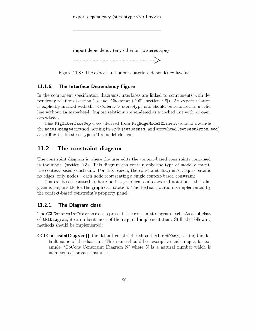
export dependency (stereotype <<offers>>)
import dependency (any other or no stereotype)
Figure 11.8.: The export and import interface dependency layouts
11.1.6. The Interface Dependency Figure
In the component specification diagrams, interfaces are linked to components with de-pendency relations (section 1.4 and [Cheesman+2001, section 3.9]). An export relationis explicitly marked with the <<offers>> stereotype and should be rendered as a solidline without an arrowhead. Import relations are rendered as a dashed line with an openarrowhead.
This FigInterfaceDep class (derived from FigEdgeModelElement) should overridethe modelChangedmethod, setting its style (setDashed) and arrowhead (setDestArrowHead)according to the stereotype of its model element.
11.2. The constraint diagram
The constraint diagram is where the user edits the context-based constraints containedin the model (section 2.3). This diagram can contain only one type of model element:the context-based constraint. For this reason, the constraint diagram’s graph containsno edges, only nodes – each node representing a single context-based constraint.
Context-based constraints have both a graphical and a textual notation – this dia-gram is responsible for the graphical notation. The textual notation is implemented bythe context-based constraint’s property panel.
11.2.1. The Diagram class
The CCLConstraintDiagram class represents the constraint diagram itself. As a subclassof UMLDiagram, it can inherit most of the required implementation. Still, the followingmethods should be implemented:
CCLConstraintDiagram() the default constructor should call setName, setting the de-fault name of the diagram. This name should be descriptive and unique, for ex-ample, ‘CoCons Constraint Diagram N’ where N is a natural number which isincremented for each instance.
90

(from org.tigris.gef.graph)MutableGraphModelSupport
<<interface>>
(from org.tigris.gef.graph)MutableGraphModel
(from org.argouml.uml.diagram.ui)UMLDiagram
(from org.argouml.ui)ArgoDiagram
(from org.tigris.gef.base)Diagram
<<interface>>
(from org.tigris.gef.graph)GraphNodeRenderer
<<interface>>
(from org.tigris.gef.graph)GraphEdgeRenderer
<<interface>>
(from ru.novosoft.uml.foundation.core)MNamespace
org.cocons.argo.diagram
ui
CCLDiagram
constraint
ConstraintGraphModel
ui
ConstraintDiagramRenderer CCLConstraintDiagram
1
#namespace
1
#model
Figure 11.9.: The constraint diagram classes (figure classes not shown)
91

CCLConstraintDiagram(MNamespace n) should call the default constructor and thenset the current model with setNamespace(n).
setNamespace(MNamespace n) is called whenever the model for this diagram is set.Since this method overrides the superclasses method, it should call super.setNamespace(n).Afterwards, it should:
1. create the proper graph model for this instance,
2. set the graph model’s namespace to n,
3. add the graph model to the diagram with setGraphModel,
4. create a new LayerPerspective with the namespace and graph model,
5. add the LayerPerspective to the diagram,
6. create a new diagram renderer,
7. add the diagram renderer as both a node renderer and an edge renderer tothe diagram.
initToolbar should create a new Toolbar instance, setting the _toolbar member inher-ited from Diagram. This toolbar should include, at the very least, a CmdCreateNodeinstance which creates new context-based constraints. Several actions are alreadyinstantiated by UMLDiagram any may also be added to the toolbar.
11.2.2. The Graph Model
The ConstraintDiagramGraphModel class is the adapter between the diagram and theuser’s model. It must implement the GraphModel interface, allowing it to visualize thecurrent model, as well as MutableGraphModel, allowing the user to manipulate the modelby editing the diagram. As a subclass of MutableGraphModelSupport, these interfacesare already partly implemented.
The GraphModel interface should be implemented as follows. Since the graph of thisdiagram does not have any edges, the edge and port methods should return null or emptyvalues.
getNodes() should return all the context-based constraints in the diagram’s graph.
getEdges() return empty vector
getPorts() return empty vector
getOwner(Object port) return null
getInEdges(Object port) return empty vector
getOutEdges(Object port) return empty vector
getSourcePort(Object edge) return null
92

getDestPort(Object edge) return null
addGraphEventListener(GraphListener listener) already implemented in superclass.
removeGraphEventListener(GraphListener listener) already implemented in superclass.
The MutableGraphModel interface should be implemented as follows.
canAddNode(Object node) should return true if the node to be added is a context-based constraint and is not already in the diagram.
addNode(Object node) should add the node to the graph as well as to the model(namespace), if not already present. Should also fire a node-added event.
removeNode(Object node) should remove the node from the graph, but not from themodel. Should also fire a node-removed event.
canAddEdge(Object edge) return false
addEdge(Object edge) do nothing (should never be called – maybe throw an excep-tion?)
removeEdge(Object edge) do nothing (should never be called – maybe throw an ex-ception?)
canConnect(Object fromPort, Object toPort) return false
connect(Object fromPort, Object toPort, Class edgeClass) do nothing (should neverbe called – maybe throw an exception?)
addNodeRelatedEdges(Object node) do nothing
canDragNode(Object node) is already implemented in superclass to always return false,which disables dragging.
dragNode(Object node) is already implemented in superclass to do nothing, which dis-ables dragging.
containsEdge(Object edge) is already implemented in superclass to use getEdges().
containsNode(Object node) is already implemented in superclass to use getNodes().
The other ArgoUML graph model classes also implement the MElementListener andVetoableChangeListener interfaces, although it is unclear whether they are actuallyused. Possibly they will be required for a future feature, so they should also be imple-mented in this graph model. Additionaly, the following methods should be implemented,as they will be called by the diagram class upon creation.
setNamespace(MNamespace m) is called when the namespace (usually the model) isset. Its implementation should register itself as a MElementListener, so it will benotified when the model is changed.
getNamespace() should return the current namespace.
93

(from org.tigris.gef.graph)MutableGraphModelSupport
<<interface>>
(from org.tigris.gef.graph)MutableGraphModel
(from org.argouml.uml.diagram.ui)UMLDiagram
(from org.argouml.ui)ArgoDiagram
(from org.tigris.gef.base)Diagram
<<interface>>
(from org.tigris.gef.graph)GraphNodeRenderer
<<interface>>
(from org.tigris.gef.graph)GraphEdgeRenderer
<<interface>>
(from ru.novosoft.uml.foundation.core)MNamespace
org.cocons.argo.diagram
ui
CCLDiagram
business_type
Business_TypeDiagramGraphModel
ui
Business_TypeDiagramRenderer CCLBusiness_TypeDiagram
1
#namespace
1
#model
Figure 11.10.: The business type diagram classes (figure classes not shown)
11.2.3. The Diagram Renderer
The ConstraintDiagramRenderer class is responsible for creating the proper figurefor any node or edge in the graph. Since the constraint diagram contains only nodesof context-based constraints, only the getFigNodeFor(Object node) must be imple-mented:
getFigNodeFor(Object node) if the node is a context-based constraint, return a newFigContextbasedConstraint representing this node. Otherwise, return null.
getFigEdgeFor(Object edge) return null.
11.3. The business type diagram
This diagram implements the global enhanced business type diagram described in sec-tion 1.3. It is very similar to UML’s static structure diagram, and can contain many ofthe same elements. This diagram is more specialized, however, since the model elementsit contains should be one of the business types (i.e. model elements of metaclass Class,but with one of the predefined business-type stereotypes).
The model elements this diagram can contain and the figures used to render thiselements is shown in the following table:
94

UML metaclass Figure Class Graph Element
MClass FigClass Node
MPackage FigPackage Node
MGeneralization FigGeneralization Edge
MAssociation FigAssociation Edge
MDependency FigDependency Edge
MContextProperty FigContextProperty Node
Table 11.1.: Business type diagram figures and model elements
11.3.1. The Diagram class
The CCLBusiness_TypeDiagram class represents the business type diagram itself. As asubclass of CoConDiagram, it can inherit most of the required implementation. Still, thefollowing methods should be implemented:
CCLBusiness TypeDiagram() the default constructor should call setName, setting thedefault name of the diagram. This name should be descriptive and unique, forexample, ‘Business Type Diagram N’ where N is a natural number which is incre-mented for each instance.
CCLBusiness TypeDiagram(MNamespace n) should call the default constructor andthen set the current model with setNamespace(n).
setNamespace(MNamespace n) is called whenever the model for this diagram is set.Since this method overrides the superclass’s method, it should call super.setNamespace(n).Afterwards, it should:
1. create the proper graph model for this instance,
2. set the graph model’s namespace to n,
3. add the graph model to the diagram with setGraphModel,
4. create a new LayerPerspective with the namespace and graph model,
5. add the LayerPerspective to the diagram,
6. create a new diagram renderer,
7. add the diagram renderer as both a node renderer and an edge renderer tothe diagram.
initToolbar should create a new Toolbar instance, setting the _toolbar member inher-ited from Diagram. This toolbar should include
• CmdCreateNode instances which create classes and packages,
• CmdSetMode instances which switch to the ModeCreatePolyEdgemode, allow-ing the addition of generalization, dependency and association edges to thediagram,
95

• the ActionAddAttribute singelton (from org.argouml.uml.ui), which al-lows the user to add an attribute to the selected class,
• the ActionAddContextProperty instance (inherited from CoConDiagram), whichallows the user to add a context-property to the selected class
Instead of a generic CmdCreateNodewhich adds an empty class to the model, it maybe desirable to use specialized commands which create a class and automaticallyassign it one the business-type stereotypes. The CmdCreateNodeStereotype (fromorg.cocons.argo.ui) class can be used for this.
11.3.2. The Graph Model
The Business_TypeDiagramGraphModel class is the adapter between the diagram andthe user’s model. It must implement the GraphModel interface, allowing it to visualizethe current model, as well as MutableGraphModel, allowing the user to manipulate themodel by editing the diagram. As a subclass of MutableGraphModelSupport, theseinterfaces are already partly implemented.
The GraphModel interface should be implemented as follows.
getNodes() should return all the nodes in the diagram’s graph.
getEdges() should return all the edges in the diagram’s graph.
getPorts() since ArgoUML assumes that each node and each edge is one big port, shouldsimply return all edges and ports in the diagram’s graph.
getOwner(Object port) since ArgoUML assumes that each node and each edge is onebig port, should simple return the object itself.
getInEdges(Object port) should return all edges currently connected with the givennode. Since the graph is not considered directed, should return the same asgetOutEdges().
getOutEdges(Object port) should return all edges currently connected with the givennode. Since the graph in not considered directed, should return the same asgetInEdges().
getSourcePort(Object edge) should return the first node of the given edge. This canbe considered as the child of a generalization, the first end of an association or theclient of a dependency
getDestPort(Object edge) should return the last node of the given edge. This can beconsidered as the parent of a generalization, the last end of an association or thesupplier of a dependency
addGraphEventListener(GraphListener listener) already implemented in superclass.
96

removeGraphEventListener(GraphListener listener) already implemented in superclass.
The MutableGraphModel interface should be implemented as follows.
canAddNode(Object node) should return true if the node is one of the metaclasses intable 11.1 and is not already in the diagram.
addNode(Object node) should add the node to the graph as well as to the model(namespace), if not already present. Should also fire a node-added event.
removeNode(Object node) should remove the node from the graph, but not from themodel. Should also fire a node-removed event.
canAddEdge(Object edge) should return true if the edge is one of the metaclasses intable 11.1, both ends of the edge are MClass nodes and the edge is not already inthe diagram.
addEdge(Object edge) should add the edge to the graph as well as to the model (names-pace), if not already present. Should also fire a edge-added event.
removeEdge(Object edge) should remove the edge from the graph, but not from themodel. Should also fire an edge-removed event.
canConnect(Object fromPort, Object toPort) should return true if both ports areMClass nodes.
connect(Object fromPort, Object toPort, Class edgeClass) should create a new in-stance of edgeClass, setting each end of the edge to fromPort and toPort. De-pending on the edgeClass, this will be the ends of an association, the child andparent of a generalization or the client and supplier of a dependency.
addNodeRelatedEdges(Object node) should add an new edge for each generalization,association and dependency connected to node and not already in the diagram.
canDragNode(Object node) is already implemented in superclass to always return false,which disables dragging.
dragNode(Object node) is already implemented in superclass to do nothing, which dis-ables dragging.
containsEdge(Object edge) is already implemented in superclass to use getEdges().
containsNode(Object node) is already implemented in superclass to use getNodes().
As with the constraint diagram, the unused MElementListener and VetoableChange-
Listener interfaces should be implemented. Additionaly, the following methods shouldbe implemented:
97

UML Metaclass Figure Class Graph Element
MClass FigClassSpec Node
MDependency FigInterfaceDep Edge
MContextProperty FigContextProperty Node
Table 11.2.: Component specification diagram figures and model elements
setNamespace(MNamespace m) is called when the namespace (usually the model) isset. Its implementation should register itself as a MElementListener, so it will benotified when the model is changed.
getNamespace() should return the current namespace.
11.3.3. The Diagram Renderer
The Business_TypeDiagramRenderer class is responsible for creating the proper figurefor any node or edge in the graph. The GraphNodeRenderer and GraphEdgeRenderer
interfaces should be implemented to return the values shown in table 11.1.Since business types typically do not have methods, setOperationVisible(false)
should be called immediatly after creating figures for classes. This will only set thedefault appearance of classes in this diagram – the user can still display the operationsby checking the appropriate box the the class property panel.
11.4. The component specification diagram
This diagram implements the enhanced component specification diagram described insection 1.5. Although the graphical notation used in this diagram is not part of thestandard UML specification, the underlaying model is. As detailed in [Cheesman+2001,section 3.9], the interface ‘lollipops’ are actually classes with the stereotype <<interfacetype>>. The relation between a component specification and an interface specificationis modeled using UML dependencies. Export interfaces are explicitly marked with an<<offers>> stereotype.
As shown in table 11.2, this diagram does not use the normal figure classes to vi-sualize the model elements. The figure classes in this diagram must be able to changetheir appearance when the stereotype of their model element changes. This stereotype-dependent behavior is encapsulated in the respective figure classes.
Since the design of this diagram is very similar to the business type diagram in theprevious section, only the differences will be mentioned here.
11.4.1. The Diagram class
The only difference between the CCLComponent_SpecDiagram class and the CCLBusi-
ness_TypeDiagram class is the contents of the toolbar. This toolbar should contain atleast the following actions:
98

• a CmdCreateNodeStereotype instance which creates a new class with the stereo-type <<comp spec>>.
• a CmdCreateNodeStereotype instance which creates a new class with the stereo-type <<interface type>>.
• a CmdSetMode instance which creates a new dependency without a stereotype,allowing the user to link an interface type to a component specification as animport interface.
• a CmdCreateEdgeStereotype instance which creates a new dependency with thestereotype <<offers>>, allowing the user to link an interface type to a componentspecification as an export interface in one step.
• the ActionAddContextProperty instance which adds a context property to theselected model element.
11.4.2. The Graph Model
The Component_SpecDiagramGraphModel’s methods should be implemented as follows.
canAddNode(Object node) should only return true if the node matches one of theclasses and stereotypes in table 11.2.
canAddEdge(Object edge) should only return true if the edge matches one of theclasses and stereotypes in table 11.2.
canConnect(Object fromPort, Object toPort) should only return true if fromPort isa <<comp spec>> and toPort is an <<interface spec>> class2.
connect(Object fromPort, Object toPort, Class edgeClass) should create a new de-pendency (edgeClass should always be MDependencyImpl), setting the supplier tofromPort and the client to toPort.
11.4.3. The Diagram Renderer
The Component_SpecDiagramRenderer methods should be implemented to return thefigures shown in table 11.2. The stereotype-dependent appearance of the metaclassesare encapsulated in the figure classes themselves.
11.5. The interface specification diagram
This diagram implements the enhanced interface specification diagram described in sec-tion 1.4. This interface types in this diagram are the same model elements as in the
99

UML Metaclass Figure Class Graph Element
MClass FigClass Node
MAssociation FigAssociation Edge
MContextProperty FigContextProperty Node
Table 11.3.: Interface specification diagram figures and model elements
component specification diagram, but they are shown here in more detail, using thestandard figure for representing classes.
Since the design of this diagram is very similar to the business type diagram, onlythe differences will be detailed here.
11.5.1. The Diagram class
The only difference between the CCLInterface_SpecDiagram class and the CCLBusi-
ness_TypeDiagram class is the contents of the toolbar. This toolbar should contain atleast the following actions:
• a CmdCreateNodeStereotype instance which creates a new class with the stereo-type <<interface spec>>.
• a CmdCreateNodeStereotype instance which creates a new class with the stereo-type <<type>>.
• a CmdCreateNodeStereotype instance which creates a new class with the stereo-type <<info type>>.
• a CmdCreateEdgeStereotype instance which creates a new association.
• the ActionAddContextProperty instance which adds a context property to theselected model element.
11.5.2. The Graph Model
The Interface_SpecDiagramGraphModel methods should be implemented as follows:
canAddNode(Object node) should only return true if the node is an instance of MClassand the stereotype is either <<interface spec>>, <<type>> or <<info type>>.
canAddEdge(Object edge) should return true if the edge is an instance of MAssocia-tion.
canConnect(Object fromPort, Object toPort) should only return true if both portsare instances of MClass.
2This will not prevent the user from retroactively changing the stereotype to an invalid configuration.A design critic could be created to catch this kind of error.
100

connect(Object fromPort, Object toPort, Class edgeClass) should create a new asso-ciation (edgeClass should always be MAssociation), setting the association endsto fromPort and toPort.
11.5.3. The Diagram Renderer
The Interface_SpecDiagramRenderer methods should be implemented to return thefigures shown in table 11.3.
11.6. The Diagram Actions
The diagrams in the previous sections add various actions to their toolbars. Most of theactions are already defined by GEF and ArgoUML, but the following action classes givethe user new possibities to edit the diagram.
The actions which allow the user to create a stereotyped model element are purelyconvenience actions – the user would get the same result by adding a model element andthen changing the stereotype in the property panel. Allowing the user to add a contextproperty is a new functon, based on the concepts introduced in the CoCons metamodel.
11.6.1. Creating Stereotyped Nodes
Normally, a diagram uses the CmdCreateNode action, which creates a new object of aspecified type (e.g. MClassImpl) before the user adds it to the diagram. This can beextended by adding a subclass CmdCreateNodeStereotype, which allows the user tocreate a new model element with a predefined stereotype in one step.
The constructor of this subclass should take one additional argument: the stereotypewhich new model elements should have. It is up to the caller (usually the diagram) toensure that the stereotype exists in the current namespace. The makeNodemethod shouldbe overridden to set the stereotype of the newly created model element before returningit to the caller.
11.6.2. Creating Stereotyped Edges
The action which creates edges is more complicated – the CmdSetMode action does notcreate new edges itself, but creates a new mode (usually ModeCreatePolyEdge), which isresponsible for creating the new edge (actually the mode uses the graph model’s connectmethod, but this is not important here).
The CmdSetMode’s constructor accepts arguments, which are later passed on to thenewly created mode. ModeCreatePolyEdge expects a single argument named ‘edge-Class’, whose value is the class of the edge to be created (e.g. MDependencyImpl).
In order to extend the edge creating step, it is therefore necessay to create a newmode which not only creates a new edge, but also sets its stereotype. This new mode,ModeCreateEdgeStereotype, should be derived from ModeCreatePolyEdge. It should
101

: Diagram
: CmdSetMode
: ModeCreateStereotypeEdge
: MDependencyImpl
mousePressed()
doIt()
initToolbar()
mouseReleased()
new(ModeCreateSterotypeEdge.class, {"edgeClass",MDependencyImpl, "defaultStereotype",myStereotype})
new({"edgeClass",MDependencyImpl, "defaultStereotype",myStereotype})
new
setStereotype(myStereotype)
Figure 11.11.: CmdSetMode and ModeCreateEdgeStereotype work together to createnew edges
be able to interpret an additional argument ‘defaultStereotype’ and set the stereotypeof the newly created edge to this value.
It is then up to the diagram to specify the stereotype to be used when creating theaction instance for its toolbar. The action passes this argument to the mode when theaction is triggered.
11.6.3. Adding Context Properties
The user should be able to add context properties to a model element directly in thediagram. This action should be able to add a FigContextProperty to the diagram,connect the figure to the model element figure with a line, and add an empty tagged valueto the model3. The user can then edit the text field in the figure directly. Parsing thetext in order to update the context property is then handled by the FigContextPropertyclass.
11.7. Integrating the diagrams in ArgoUML
New menu items must be added to the application menu bar to enable the user to usethe new diagrams. These new menu items are represented by subclases of UMLAction.Whenever a menu item is selected, its actionPerformed method is invoked. To enablethe user to create a new diagram, this method should to implemented to:
1. create a new instance of the specific diagram class (e.g. CCLConstraintDiagram)for the current model.
3This is very similar to the ActionAddNote action, which allows the user to add a note to a modelelement
102

(from org.argouml.uml.ui)UMLAction
org.cocons.argo.diagram
ui
ActionBusiness_TypeDiagram
ActionInterface_SpecDiagram
ActionConstraintDiagram
ActionComponent_SpecDiagram
Init
AbstractAction
{abstract}(from javax.swing)
Figure 11.12.: Diagram menu item classes
2. add the new diagram to the current project.
3. add the diagram to the navigator pane’s history stack so the user can undo thefollowing target change.
4. set the project browser’s target to the new diagram.
5. notify the project that unsaved changes have occured.
6. notify allActions that the project state has changed.
The Init class will be used by the plugin initialization (section 12.4) and is responsiblefor creating the actions and adding them to the appropriate pull-down menu. Thiscan either be done in Init’s constructor (then then new menu items will be availableimmediatly at the cost of a slightly longer application load time) or in the run method(faster application loading, but the menu items will not appear until after the post-loadphase).
103

12. Extending the ArgoUML Workspace
The diagrams may be the main user interface component1 of ArgoUML, but the othercomponents are just as important. These components must also be extended to supportthe CoCons metaclasses and other CCL concepts.
Although the graphical representation of a model does have its merits, some aspectsof a model can not be adaquately represented in a visual notation. One example of this isthe definition of stereotype. For this reason, ArgoUML includes a Details Pane which isdisplayed under the diagram. Section 12.1 describes how to extend this pane to supportthe new CoCons metaclasses.
To the left of the diagram pane is the Navigator Pane, showing the user’s model ina tree-like structure. This pane allows the user to quickly navigate to any part of themodel. Section 12.2 shows which classes must be added to enable this pane to supportthe new CoCons metaclasses.
All of these components are based on java’s Swing class library. Since this libraryis very well documented ([Java2API] and [Swing]) this section will concentrate on thespecification of the new UI components. Working out the design details of these UIcomponents should be quite straightforward for any experienced java/Swing developer.
12.1. Extending the Details Pane
The details pane (see section 8.2) contains several tabs which show different aspects ofthe user’s model. By implementing TabModelTarget, these tabs are notified wheneverthe user selects a new object (the target). The target can be an element from the user’smodel or anything else which can be selected in the navigator panel (e.g. a diagram).
Most of these tabs have constant contents (e.g. the ‘constraints’ tab) and are enabledwhenever they are valid for the current target. This is a good position to add the ‘taggedvalues’ tab, since this tab should be available whenever the target is an instance of aMModelElement.
One of the details pane’s tabs is the ’properties tab’ – this tab shows the attributesand roles of the current target. Since each target has different attributes and roles(depending on its metaclass) the contents of this tab must be dynamic. This is achievedthrough property panels – each metaclass has its own property panel (derived fromPropPanel) which supplies this tab with the appropriate contents.
1In this chapter, in order to impove readability, ‘component’ is used to refer to a ‘Swing UI component’.This is not the same as the ‘software component’ concept.
104

PropPanelModelElement
(from org.argouml.uml.ui.foundation.core)
{abstract}
PropPanel
(from org.argouml.uml.ui)
{abstract}
(from org.argouml.uml.ui.foundation.extension_mechanisms)
PropPanelStereotype
(from org.argouml.uml.ui)
TabModelTarget<<interface>>
(from org.argouml.ui)
TabSpawnable
org.cocons.argo.ui
PropPanelContextCondition PropPanelContextbasedConstraint PropPanelStereotype
PropPanelTagDefinitionPropPanelTaggedValue
PropPanelContextPropertyTag
TabTaggedValues
Figure 12.1.: The plugin’s details pane classes
105

Tagged Values
Values
CreateNewCustomer, CreateNewContract
Internetcomp spec
comp spec
Workflow
Tier
Personal Data
Author
OwnerTag
Al Bundy
Figure 12.2.: The tagged values tab layout
Each metaclass should have its own property panel showing the details of the selectedelement, allowing the user to modify the attribute values and links well as navigatethrough the model. The property panels are subclassed from the PropPanelModelEle-
ment class.These property panels classes should be registered with the details pane by the plugin
(appendix A.2.3) to enable ArgoUML to display them as required. If this is done in theInit.run method (section 12.4) these property panels will replace any of ArgoUML’sbuilt-in panels which are registered for the same metaclass.
Each property panel consists of various sub-components. In the org.argouml.uml.uipackage, ArgoUML already defines many specialized UI components which can be mappedto roles and attributes in the user’s model.
12.1.1. The Tagged Values Tab
This tab displays all the tags for the currently selected model element (ArgoUML alreadyhas a tagged values tab, but this class only supports UML 1.3-style tagged values). Sincecontext properties are modeled using tagged values (section 2.2), the context propertiesare displayed as well.
This tab contains a table (a swing JTable) showing all the tags the selected modelelement may have, what stereotype defines them, and any current values. An icon isshown in the first column if the tag definition is a context property tag.
Double-clicking on a tag should change the target to the selected tag defintion, whichresults in the tag definition property panel (or the context property tag panel) beingdisplayed. Double clicking on the stereotype should change the target to the stereotype.The last column of the table should be editable, allowing the user to edit the taggedvalues directly.
12.1.2. The Stereotype Property Panel
ArgoUML’s stereotype property panel does not support tag definitions, so a new stereo-type property panel is required. This new panel can inherit all the UI components fromArgoUML’s built-in stereotype panel and simply add a new label and list box to thelayout showing the tag definitions.
106

<< >>
Properties
<< >> Stereotype
Name
Base Class
Namespace
Extends
Modifiers abstract final root
Derived
Tag Definitions
Figure 12.3.: The stereotype panel layout
i
Properties
Name
Context−based Constraint
Body
Namespace
Constrained Stereotype
Constrained Set
Constrained Elements
Scope Set
Scope Elements
Figure 12.4.: The context-based constraint property panel layout
As with the tagged values tab, this list box should show context property tags withthe appropriate icon. This list box should also support a context-menu with the followingitems:
open sets the target to the selected entry. This will display either the tag definitionproperty panel or the context property tag panel, depending on the type of theentry.
add tag definition creates a new, empty tag defintion and adds it to the stereotype.
add context property creates a new, empty context property and adds it to the stereo-type
delete removes the selected entry from the stereotype
Double-clicking on an item in this list-box should be equivalent to selecting ’open’ fromthe context-menu.
12.1.3. The Context-based Constraint Property Panel
This panel shows the attribues and roles of a context-based constraint in its textualform.
107
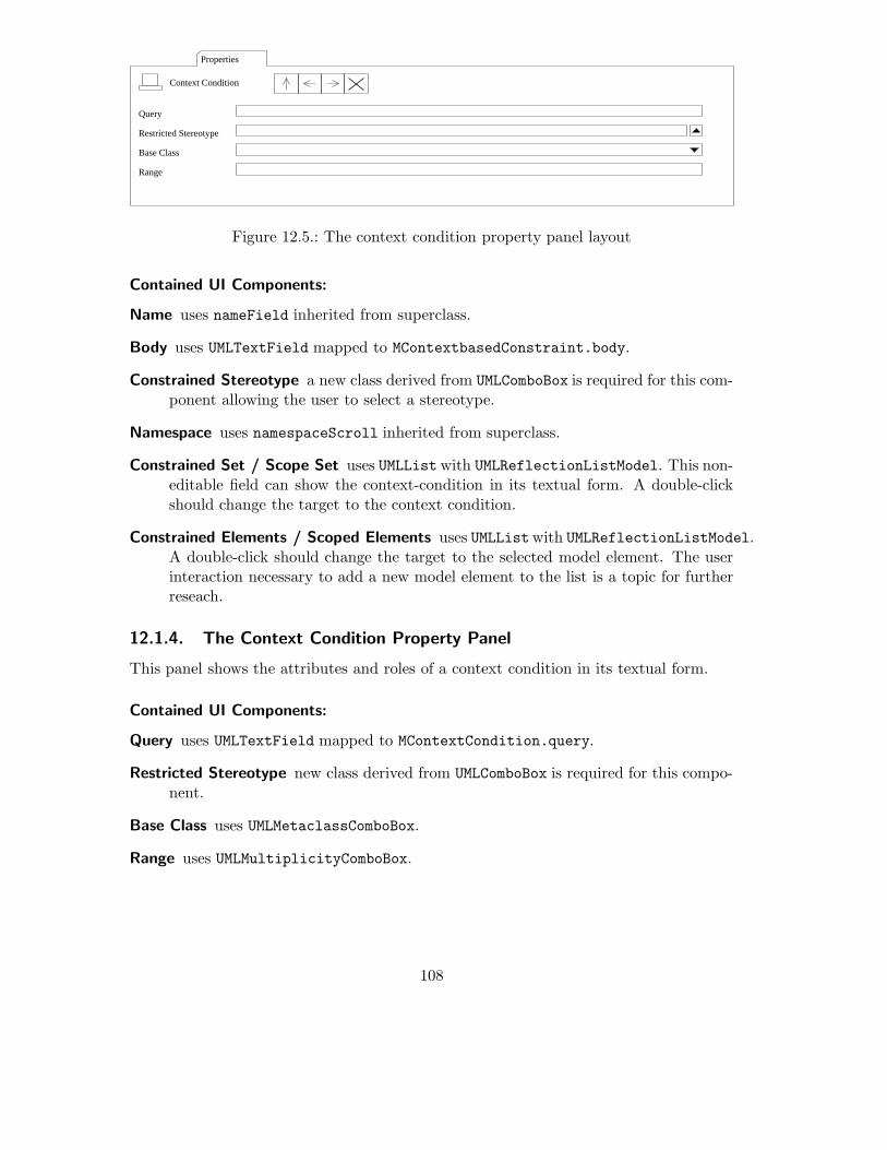
Properties
Context Condition
Range
Base Class
Restricted Stereotype
Query
Figure 12.5.: The context condition property panel layout
Contained UI Components:
Name uses nameField inherited from superclass.
Body uses UMLTextField mapped to MContextbasedConstraint.body.
Constrained Stereotype a new class derived from UMLComboBox is required for this com-ponent allowing the user to select a stereotype.
Namespace uses namespaceScroll inherited from superclass.
Constrained Set / Scope Set uses UMLListwith UMLReflectionListModel. This non-editable field can show the context-condition in its textual form. A double-clickshould change the target to the context condition.
Constrained Elements / Scoped Elements uses UMLListwith UMLReflectionListModel.A double-click should change the target to the selected model element. The userinteraction necessary to add a new model element to the list is a topic for furtherreseach.
12.1.4. The Context Condition Property Panel
This panel shows the attributes and roles of a context condition in its textual form.
Contained UI Components:
Query uses UMLTextField mapped to MContextCondition.query.
Restricted Stereotype new class derived from UMLComboBox is required for this compo-nent.
Base Class uses UMLMetaclassComboBox.
Range uses UMLMultiplicityComboBox.
108

{}
Properties
Name
Tag Definition
Namespace
Owner Multiplicity
TagType
Figure 12.6.: The tag definition property panel layout
Properties
Name
Namespace
Owner Multiplicity
TagType
Value Validation
Context Property Tag
Figure 12.7.: The context property tag panel layout
12.1.5. The Tag Definition Property Panel
This panel shows a UML 1.4 tag definition.
Contained UI Components:
Name uses nameField inherited from superclass.
Owner a new class derived from UMLComboBox is required for this component allowingthe user to select a stereotype.
Namespace uses namespaceScroll inherited from superclass.
TagType uses UMLTextField mapped to MTagDefinition.tagType.
Multiplicity uses UMLMultiplicityComboBox.
12.1.6. The ContextProperyTag Property Panel
This panel shows a context property tag.As a subclass of the tag defintion panel, only the ValueValidation component must
be added:
109

ValueValidation uses UMLList with UMLReflectionListModel. This non-editable fieldcan show constraint which validates the context properties. A double-click shouldchange the target to the constraint.
12.2. Extending the Navigator Pane
ArgoUML’s navigator pane (section 8.3) shows the user’s model in various tree-likeperspectives. These perspectives should be extended to support the new metaclasses.
The ’package-centric’ perspective needs new branching rules to show the context-based constraints. Since a constraint can either be owned by a namespace or a stereotype,the following rules are required:
Namespace-to-Context-based Constraint Since a model is derived from namespace,this rule enable the perspective to show all the context-based constraints not ownedby a stereotype. This rule can be constructed with a GoModelElement rule com-bined with a GoFilterChildren instance configured to return only context-basedconstraints.
Namespace-to-Stereotype will enable a perspective to show all stereotypes in a names-pace. This rule can be constructed with a GoModelElement rule combined with aGoFilterChildren instance configured to return only stereotypes.
Stereotype-to-Context-based Constraint will enable a perspective to show all context-based constraints owned by a stereotype. This rule requires a new class implement-ing the TreeModelPrereqs interface. It should follow the stereotypeConstraint
role of a stereotype.
Another possibility would be a new ’CoCons-centric’ perspective showing the context-based constraints and context-property tags in the model:
Project-to-Model forming the root of the tree. This is already implemented by theGoProjectModel class.
Namespace-to-Package showing the package hierarchy in the model. This rule is al-ready instantiated by NavPerspective as modelToPackages.
Namespace-to-Stereotype showing all stereotypes in a namespace.
Namespace-to-Context-based Constraint showing the context-based constraints notowned by a stereotype.
Stereotype-to-Context-based Constraint showing the context-based constraints ownedby a stereotype.
Namespace-to-Context Property Tag showing the context property tags not owned bya stereotype. This rule can be constructed with a GoModelElement rule combinedwith a GoFilterChildren instance configured to return only context property tags.
110
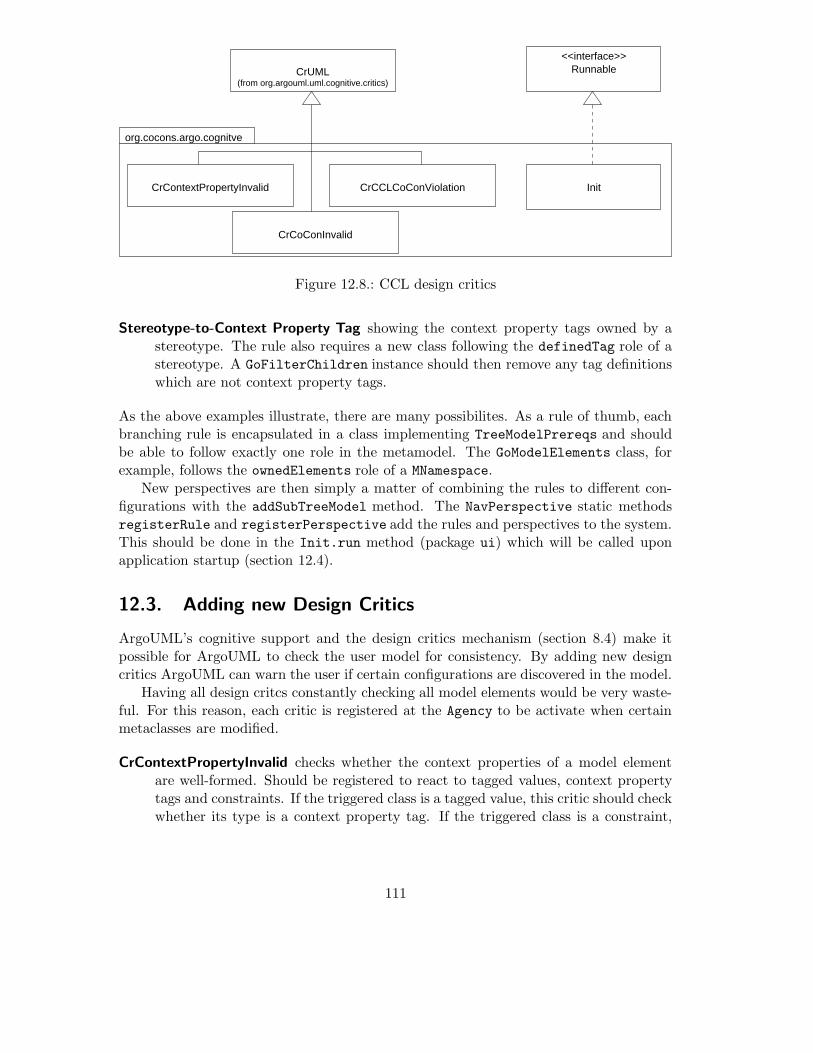
(from org.argouml.uml.cognitive.critics)CrUML
org.cocons.argo.cognitve
<<interface>>Runnable
CrCCLCoConViolationCrContextPropertyInvalid
CrCoConInvalid
Init
Figure 12.8.: CCL design critics
Stereotype-to-Context Property Tag showing the context property tags owned by astereotype. The rule also requires a new class following the definedTag role of astereotype. A GoFilterChildren instance should then remove any tag definitionswhich are not context property tags.
As the above examples illustrate, there are many possibilites. As a rule of thumb, eachbranching rule is encapsulated in a class implementing TreeModelPrereqs and shouldbe able to follow exactly one role in the metamodel. The GoModelElements class, forexample, follows the ownedElements role of a MNamespace.
New perspectives are then simply a matter of combining the rules to different con-figurations with the addSubTreeModel method. The NavPerspective static methodsregisterRule and registerPerspective add the rules and perspectives to the system.This should be done in the Init.run method (package ui) which will be called uponapplication startup (section 12.4).
12.3. Adding new Design Critics
ArgoUML’s cognitive support and the design critics mechanism (section 8.4) make itpossible for ArgoUML to check the user model for consistency. By adding new designcritics ArgoUML can warn the user if certain configurations are discovered in the model.
Having all design critcs constantly checking all model elements would be very waste-ful. For this reason, each critic is registered at the Agency to be activate when certainmetaclasses are modified.
CrContextPropertyInvalid checks whether the context properties of a model elementare well-formed. Should be registered to react to tagged values, context propertytags and constraints. If the triggered class is a tagged value, this critic should checkwhether its type is a context property tag. If the triggered class is a constraint,
111

it should be the value validation of a context property tag. Otherwise, the criticshould immediatly exit in order not to waste processing resources.
CrCoConInvalid checks whether context-based constaints are well-formed. Should beregistered to react to context-based constraints and context conditions.
The definitions of ‘well-formedness’ can be found in [Bubl2001-CoCons].
CrCoConViolated checks whether any model elements violate a context-based con-straint. The indirect nature of context-based constraints make this critic veryprocessor-intensive, since it must be activated whenever any model element it mod-ified. Possibile optimization strategies are a further research topic.
The Init class (used by the plugin package, section 12.4) is responsible for registeringthese critics and should be performed in the run method, as to not increase applicationloading time. The method Agency.register is used to register a single critic to reactto a single metaclass – by calling this method multiple times the same critic can reactto multiple metaclasses.
12.4. Plugin Initialization
Whereas section 9.1 outlines the plugin mechanism from an abstract, generic perspective,this section will give a more detailed description of the concrete plugin mechanism andspecificy the interface to the plugin.
ArgoUML uses a two-phase initialization: the mainmethod of the Application.Mainclass performs the first phase by instatiating and initializing the classes the user willimmediatly need (e.g. the user interface panes). In order to avoid a long delay whenstarting ArgoUML, a second phase, running in a background thread, is used to preloadclasses and build up the various registries. In this second phase, the property panels areregistered with the details pane, the design critics are started, the navigator perspectivesare constructed and many UML metaclasses are preloaded.
The ArgoUML Plugin interface is based on the plugin architecture introduced in 9.1.To keep things simple, ArgoUML requires the plugin to implement the class ArgoPluginwhich has only two methods: init() and getPostLoadActions().
init() in invoked immediately after the plugin is loaded.
getPostLoadActions() should return a vector of post-load actions implementing Runnable.These actions run after all application post-load actions are executed.
With the getPostLoadActions method, the plugin is able to add its own initializationclasses to the second phase. This is necessary since many of the structures created bythe application during this phase must be modified by the plugin.
Each of the plugin’s main package groups export a class Init implementing Runnable.The plugin instantiates these classes and passes them to the application – encapsualtingthe initialization details in the individual packages.
112

:CCLPlugin
:diagram.Init
:cognitive.Init
:ui.Init
:Postload
:argouml.Main
init()
new
main()
getPostLoadActions()
new
new
run()* postLoadActions()
run()
run()
new
new
run()
Figure 12.9.: The plugin’s Init objects are executed in a background thread
113

org.cocons.argo
ui plugin
cognitive diagram
Init Init
Init CCLPlugin
Figure 12.10.: Each top-level package has its own Init class
114

13. Conclusion
The open source modelling tool ArgoUML served as a starting point for this work - theavailability of the source code making extensions possible. As with many open sourceprojects, up-to-date documentation describing the overall design was far from sufficient.Part II of this work, the analysis of the ArgoUML architecture, resulted out of necessity- and will hopefully help other developers in the ArgoUML community.
Software components are considered as the main structuring mechanism in order tosupport continuous software engineering [Große-Rhode+2000]. By extending the Ar-goUML modelling tool with the plugin mechanism, ArgoUML is transformed from amonolithic application to a component-based system, allowing plugins to be developedand distributed independently from ArgoUML itself. The resulting system can serveas an experimental platform for furthur research in the area of model based softwaredevelopment.
Designing a modelling tool supporting the context-based constraint language was theprimary motivation for this thesis. The CCL-Plugin serves not only as a proof-of-conceptfor the plugin mechanism, but also opens the possibility to evaluate the advantages ofcontext-based constraints in real-world modelling projects.
115

A. Necessary Source Modifications
A.1. Bugfix in package ru.novosoft.uml.undo
The member variable MCheckPoint.stackPosition should always reflect the currentposition of this checkpoint on the undo-stack. When items are removed from somewherein the middle of the stack (which happens in the MCheckPointUndoManager.forget
method) the position of all objects ‘above’ the removed object change – but their stack-Position variable is not updated:
/** forget information about all changes done before this checkpoint */
public static void forget(MCheckPoint c)
{
// ...
for (int i = currentCheckPointPosition-1;i>=0;i--)
{
undoStack.remove(0);
}
currentCheckPointPosition = c.stackPosition;
}
Since items are removed from the middle of the stack, the stackPosition member vari-able no longer has the correct value, and, as a result, currentCheckPointPosition isthen also incorrect. This can result in a ClassCastException in the method getCheck-
Point, since undoStack.get( currentCheckPointPosition ) points to something un-defined.
The quick solution is simply to add
c.stackPosition = undoStack.indexOf(c);
after the loop and before the assignment – making sure stackPosition has the correctvalue.
This is probably not a complete solution, but since only forget( getCheckpoint()
) (clearing the entire stack except the last item) is called in the application, it is sufficient.It would probably be better to remove the member variable stackPosition com-
pletely, replacing it with calls to undoStack.indexOf() throughout the code.
A.2. Modifications to the ArgoUML sources
Although one of the goals was not to modify any of the ArgoUML sources, in a fewcases this simply can not be avoided. The following sections describe what modifications
116

are necesary. These modification have all been designed not to have any unwanted side-effects. ArgoUML will still behave as before when used with the original NSUML library.Hopefully these modifications will be incorporated into the main source trunk1.
A.2.1. The plugin package
All classes implementing the plugin mechanism (section 9.1) are located in the packageorg.argouml.util.plugin. The following static methods should be added to the classMain (in package org.argouml.application):
Main.getPlugins should create a PluginManager instance and return an array of foundplugins by calling getPluginFiles().
Main.initPlugins should instantiate and initialize each of the plugins. It should alsoquery each plugin for any postload actions, adding these actions to the application’spostLoadActions vector.
protected static Vector getPlugins() {
PluginManager _pm = new PluginManager("ArgoUML-Plugin");
return _pm.getPluginFiles();
}
protected static void initPlugins(Vector plugins) {
Iterator i = plugins.iterator();
while (i.hasNext()) {
PluginSource ps = (PluginSource) i.next();
try {
Class c = ps.loadClass();
ArgoPlugin plugin = (ArgoPlugin) c.newInstance();
plugin.init();
postLoadActions.addAll(plugin.getPostLoadActions());
}
catch (ClassNotFoundException e) {
// handle error
} catch (InstantiationException e) {
// handle error
} catch (IllegalAccessException e) {
// handle error
}
}
Main.main should then invoke these methods at the appropriate place:
public static void main(String args[]) {
...
// Initialize the module loader.
Argo.initializeModules();
// CCL Plugin Loader
initPlugins(getPlugins());
...
}
1In matter of speaking, the goal of this section is to make itself obsolete.
117

A.2.2. Accessing the Application Menu Bar
The main application window of ArgoUML is represented by the ProjectBrowser class.This class contains the application menu bar in the protected member variable _menubar.
Since the CCL plugin will need access to this member in order to add new menuitems, the following method must be added to ProjectBrowser:
A.2.3. Extendable Property Panels
In the present version, a list of the different property panels (section 8.2) for the variousmetaclasses are hard-coded in the TabProps class (package org.argouml.uml.ui). Thisprevents plugins from adding their own property panels.
The following addition allows a new property panel to be registered with the propertytab at run-time:
package org.argouml.uml.ui;
class TabProps
{
...
public void addPanel(Class c, PropPanel p)
{
_panels.put(c,p);
}
}
Since the property tab is contained by the details pane, adding the following methodallows the plugin to add a new property panel through a well-known access point:
package org.argouml.ui;
class DetailsPane
{
...
public void addToPropTab(Class c, PropPanel p)
{
for (int i = 0; i < _tabPanels.size(); i++)
{
if (_tabPanels.elementAt(i) instanceof TabProps)
{
((TabProps)_tabPanels.elementAt(i)).addPanel(c,p);
}
}
}
}
A.2.4. The extended NSUML library
In order to support the CCL metamodel extensions, the NSUML library has been modi-fied to support a subset of the UML 1.4 specification. Unfortunalty, there are a few caseswhere UML 1.4 is not compatible with UML 1.3. Since ArgoUML is based on UML 1.3,a few classes must be changed to support the modified library.
118

Tagged Values and Tag Definitions
The concept of tagged values has been extended considerably in UML 1.4. Tagged valuesare now specified by a tag definition, which is linked to a stereotype, and can containmore than one value.
In order to still support UML1.3-compatible tagged values, the UML1.4 metamodelallows tag definitions which are not linked to a stereotype, but which are owned by thenamespace of the model element2.
In order to keep the NSUML object model backward-compatible, the UML1.3 mu-tators of MTaggedValue (setTag, setValue), have been modified to create UML 1.3-compatible tag definitions automatically, with one restriction: the tagged value mustalready be linked with a model element before calling these methods. Using these meth-ods on a non-UML 1.3-compatible tagged value will result in an exception. The UML1.3inspectors getTag and getValue have been modified to return the correct values as longas they are used on a UML 1.3-compatible tagged value. Using these methods on anon-UML 1.3 compatible tagged value will return null values.
The following methods in the ArgoUML sources must be modified to conform withthe above restriction:
Method setProperty of UMLTaggedBooleanProperty: adding the tagged value tothe element must be done before setting the tag and value:
if (!found) {
MTaggedValue taggedValue = new MTaggedValue();
element.addTaggedValue(taggedValue); // do first
taggedValue.setTag(_tagName);
if (newState) {
taggedValue.setValue("true");
}
else {
taggedValue.setValue("false");
}
// element.addTaggedValue(taggedValue);
}
In the method setValueAt of TabTaggedValues:
if (tvs.size() == rowIndex) {
MTaggedValue tv = new MTaggedValueImpl()
tv.setModelElement(_target); // do first
if (columnIndex==0) tv.setTag((String)aValue);
if (columnIndex==1) tv.setValue((String)aValue);
tvs.addElement(tv);
fireTableStructureChanged(); //?
_tab.resizeColumns();
}
As long as only UML1.3 compatible tagged values are used, and the above restriction ismet, the modified NSUML library will behave in a fully UML1.3 compatible manner.
2an example of this is tag ‘legacy tag’ in figure 10.3.
119

Stereotypes
The attribute baseClass has changed from String to String[*] in UML 1.4. The UML1.3inspector getBaseClass will now return the first base class of the stereotype. Themutator setBaseClass will remove all current base classes and add the new base class.As long as the application uses base classes in a UML1.3 manner (each stereotype havingonly one base class), the library will behave in a fully UML1.3 compatible manner andrequire no changes to the application.
120

Bibliography
[Bubl2001-CCL] Bubl, Felix. The Context Based Component Constraint Language,TU Berlin, 2001
[Bubl2001-CoCons] Bubl, Felix. Requirements Engineering via Context-Based Con-straints, TU-Berlin, 2001
[Große-Rhode+2000] Martin Große-Rhode, Ralf-Detlef Kutsche, Felix Bubl, Conceptsfor the Evolution of Component-Based Software Systems, Fach-bereich Informatik, Technische Universitat Berlin, 2000
[Gamma+95] Gamma, Helm, Johnson, Vlissides. Design Patterns, Elements ofReusable Object-Oriented Software, Addison-Wesley, 1995
[Beck2000] Kent Beck, Extreme Programming Explained: Embrace Change,Addison-Wesleym 2000
[Venners99] Bill Venners. Design Techniques – Designing withDynamic Extension, JavaWorld January 1999(http://www.artima.com/designtechniques/index.html)
[Fowler97] Martin Fowler. UML Distilled – Applying the Standard ObjectModeling Language, Addison-Wesley, 1997
[Cheesman+2001] John Cheesman, John Daniels. UML Components – A Simple Pro-cess for Specifying Component-Based Software, Addision-Wesley,2001
[nsuml] The Novosoft UML API (http://nsuml.sourceforge.net)
[argouml] The ArgoUML Project (http://argouml.tigris.org)
[gef] The Java Graph Edting Framework GEF (http://gef.tigris.org)
[junit] The Java Unit Testing Framework JUnit (http://www.junit.org)
[Wake2000] William C. Wake, The Test/Code Cycle in XP, XPlorations,Febuary 2000 (http://users.vnet.net/wwake/xp/xp0002/ )
[Java2API] Java 2 Platform, Standard Edition, v 1.3.1 API Specification(http://java.sun.com/j2se/1.3/docs/api/index.html)
121

[Swing] Creating a GUI with JFC/Swing,(http://java.sun.com/docs/books/tutorial/uiswing/index.html)
[UML1.3] OMG Unified Modeling Language Specification, Version1.3 (http://www.omg.org/technology/documents/formal/ uni-fied modeling language.htm)
[UML1.4draft] OMG Unified Modeling Language Specifi-cation, Version 1.4 draft February 2001(http://www.omg.org/technology/documents/recent/omg modeling.htm)
[XMI1.1] OMG XML Metadata Interchange (XMI) Specification, Version1.1
122