Embed Size (px)
Citation preview
Engineering Graphics
Welcome to E GR 1207Welcome to E GR 1207
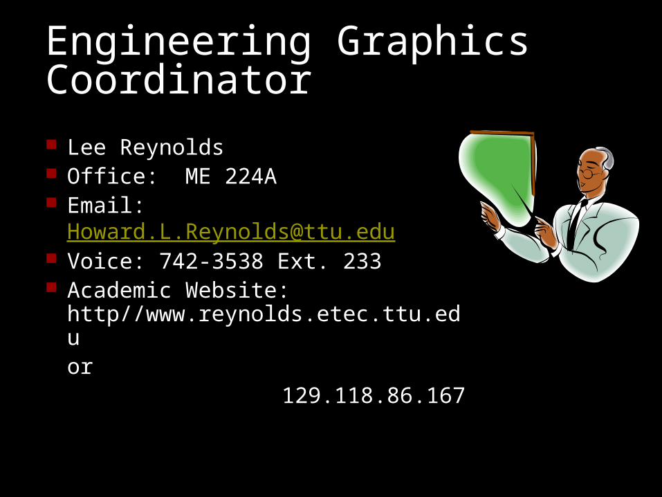
Engineering Graphics Coordinator
Lee Reynolds Office: ME 224A Email: [email protected] Voice: 742-3538 Ext. 233 Academic Website:
http//www.reynolds.etec.ttu.eduor
129.118.86.167
Your Instructor:
Office Hours: Email Contact:
Semester Topical Overview
Graphic Language & Design
CAD Systems Sketching Techniques Lettering Geometric
Constructions
Multiview Projection Sectional Views Auxiliary Views Dimensioning Tolerancing Working Drawings

Lecture Overview
Engineering Graphics Language The Design Process Parallel & Perspective Projection Lettering Practices Homework
Course Title: E GR 1306Lesson Title: Design and Graphic Communication
Objectives: After completing this unit, the student should be able to:
Define engineering graphics. Explain why standards are important. List the stages of the design process. Name the three phases of concurrent engineering. Explain the difference between parallel and perspective
drawing. Apply proper lettering technique.
Define concurrent engineering. Explain the importance of computer-aided
design, engineering, and manufacturing. Explain the importance of prototypes and
rapid prototyping
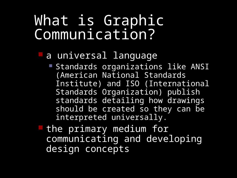
What is Graphic Communication? a universal language
Standards organizations like ANSI (American National Standards Institute) and ISO (International Standards Organization) publish standards detailing how drawings should be created so they can be interpreted universally.
the primary medium for communicating and developing design concepts
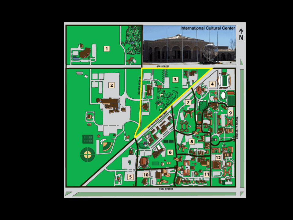
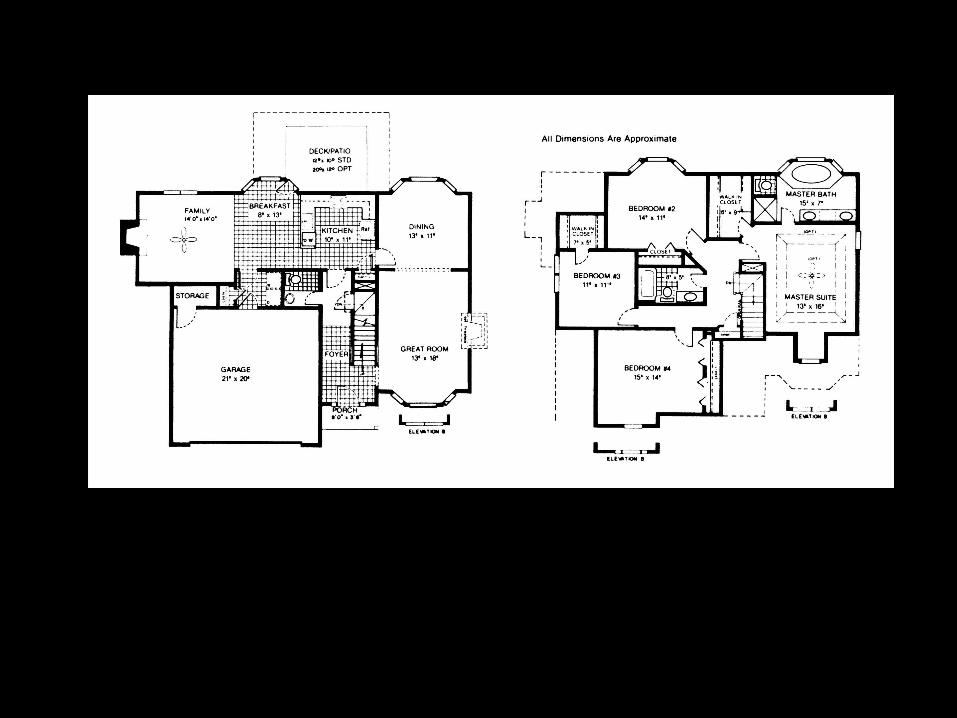
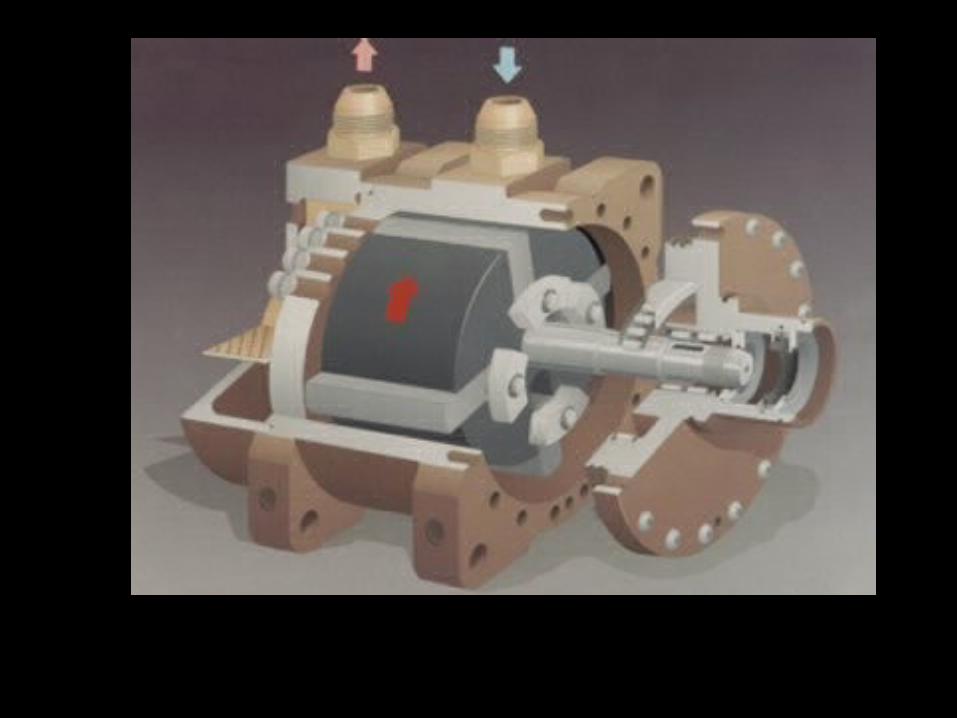
Visualization ExamplesEngineering Graphics in the Design Process

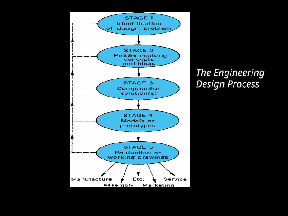
The EngineeringDesign ProcessThe EngineeringDesign Process
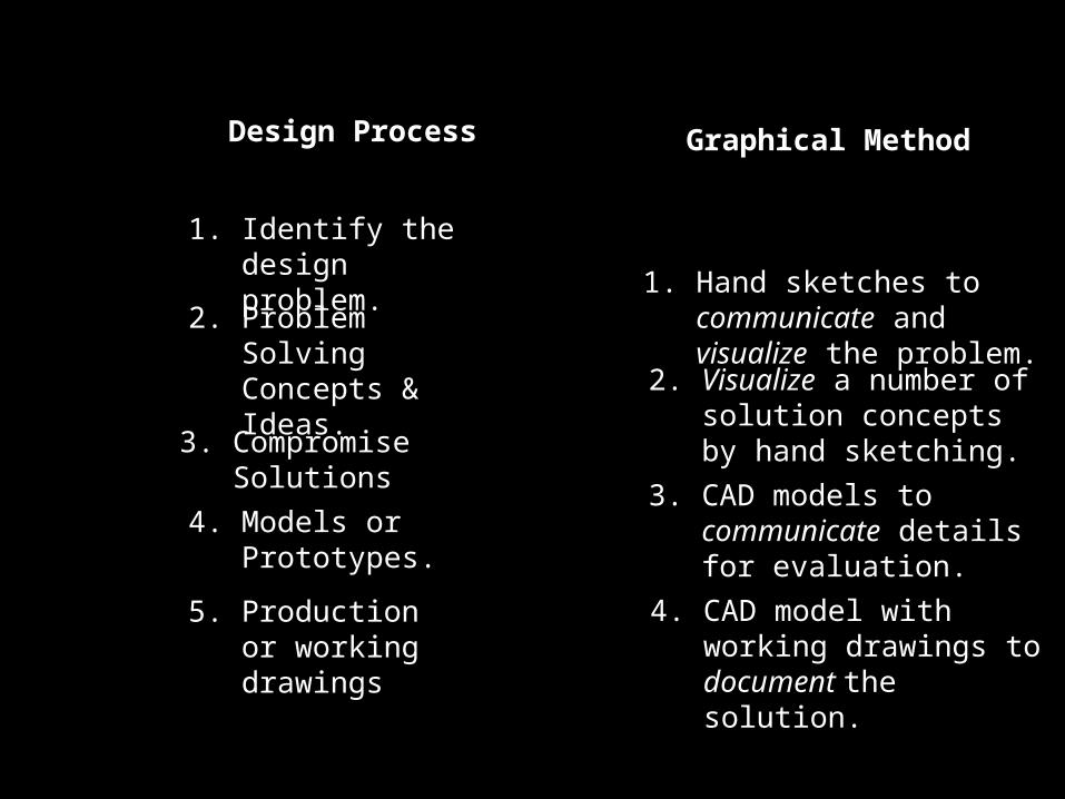
Design Process Graphical Method
1. Identify the design problem.
2. Problem Solving Concepts & Ideas.
3. Compromise Solutions
4. Models or Prototypes.
5. Production or working drawings
1. Hand sketches to communicate and visualize the problem.
2. Visualize a number of solution concepts by hand sketching.
3. CAD models to communicate details for evaluation.
4. CAD model with working drawings to document the solution.
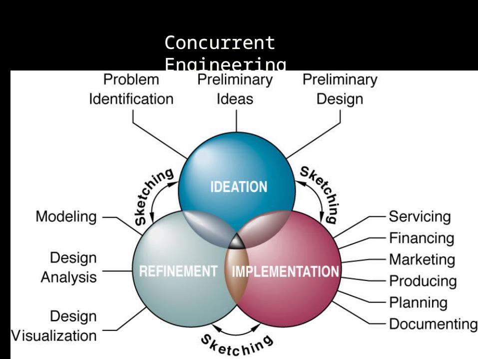
Concurrent EngineeringConcurrent Engineering
Engineering DesignUses Sketching & CAD Ideas are initially sketched and then more
accurate CAD drawings are created A single accurate CAD database can be used
to go from ideation to manufacturing and documentation.
Finite Element Analysis, 3D rendering, animation, documentation, rapid prototyping software are available for use with CAD.
Terminology
CAD: Computer Aided Design CADD: Computer Aided Design & Drafting CAM: Computer Aided Manufacturing CIM: Computer Integrated Manufacturing CAE: Computer Assisted Engineering Reading Drawings: Interpreting drawings made by others Technical Drawing: Drawings used to express technical
ideas Engineering Design Graphics: Technical Drawings representing designs & specifications for physical objects
Freehand Sketching
Freehand sketching is used in engineering graphics to quickly communicate your ideas or designs.
A CAD program may not be available, especially during field work
Freehand sketching is not sloppy sketching! Your sketches need to be interpreted by others on your design team
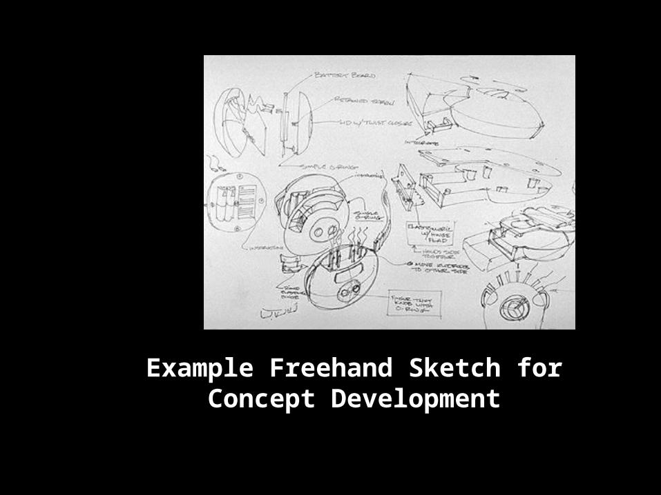
Example Freehand Sketch for Concept Development
Lettering Basics
Use HB or other medium grade pencil (2H)
Typical lettering height is 1/8”
Lettering is Vertical and UPPERCASE
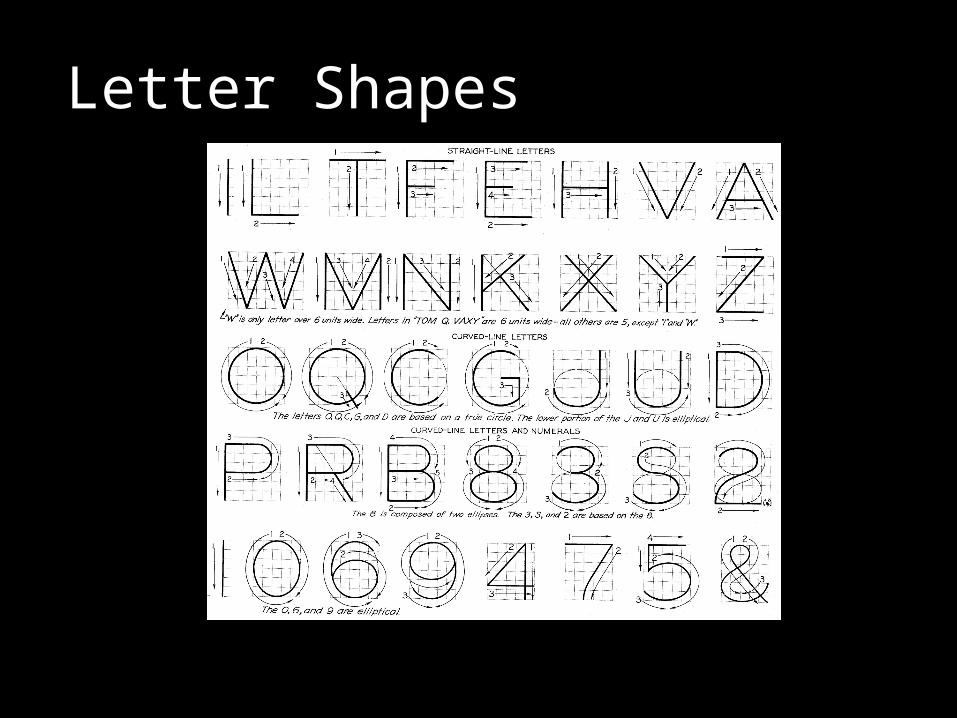
Letter Shapes
You can think of each letter as being formed on a 6 x 6 grid.
Most letters are 5 units wide by 6 units tall.
T O M Q V A X and Y are all 6 units by 6 units.
Letter W is 8 units wide and 6 units tall
Letter I and numeral 1 are only the width of a single stroke.
Letter Shapes
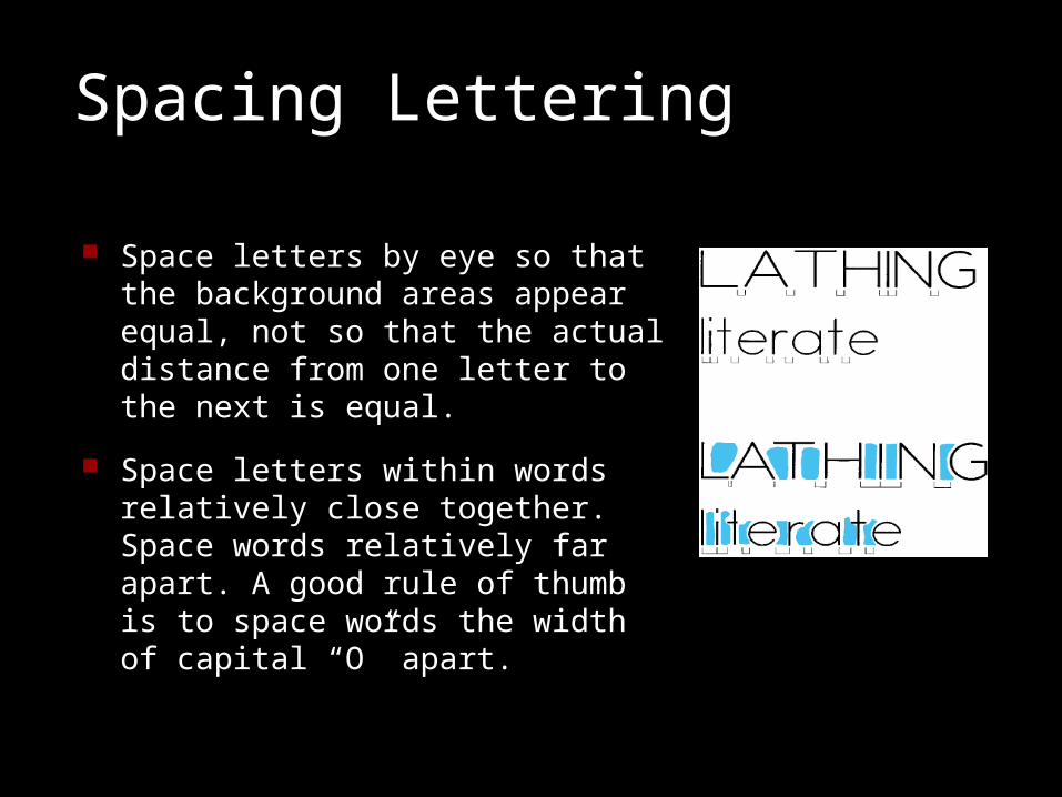
Spacing Lettering
Space letters by eye so that the background areas appear equal, not so that the actual distance from one letter to the next is equal.
Space letters within words relatively close together. Space words relatively far apart. A good rule of thumb is to space words the width of capital “O” apart.
Remember!!
Neat legible lettering is used to add dimensions and notes to sketches.
Poor lettering can ruin an otherwise good sketch.
Engineering lettering is usually drawn with HB or other relatively soft lead.
Use vertical, uppercase single-stroke letters
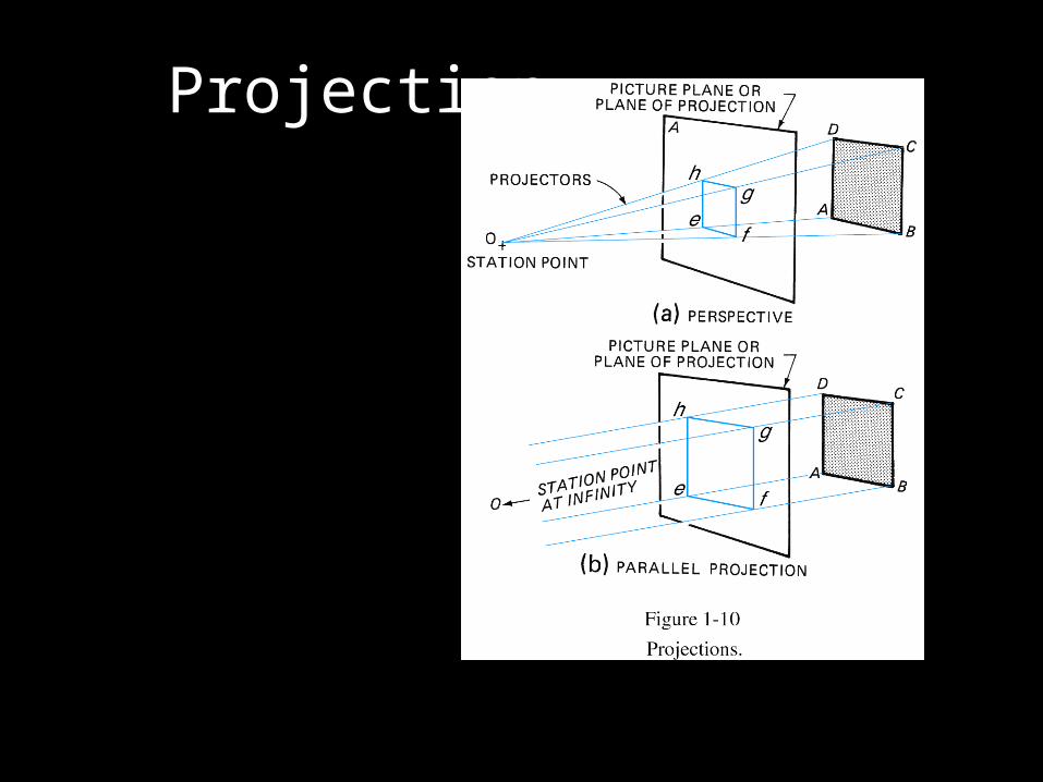
Projection
Fundamental Axioms
Axiom 1: If a planar surface is parallel to a projection plane, then that planar surface will project true size onto the projection plane.
Axiom 2: Points transfer orthogonally into adjacent views.
Summary
Engineering drawing can be a universal language to communicate your ideas.
The engineering design process uses sketching and CAD to communicate and record ideas.
A single CAD database can be used to produce many types of drawings and models used throughout the design process.
Assignment for next class meeting