Embed Size (px)
Citation preview

Engineering Data Pack
Excellence at work. Excellence in life.
GlobalGear® Series Pump Metric
V 1.28

Page 2 of 36V 1.29
Table of Contents
GG015 - GG030 with Angle Ports (Flanged Only)
Mounting Dimensions 3
IG015I - IG030I with Integral Angle Ports (NPT Only)
Mounting Dimensions 4
GG015 - GG030 with Side Ports (Flange Only)
Mounting Dimensions 5
IG015I - IG030I with Integral Side Ports
Mounting Dimensions 6
GG050 - GG070 with Angle Ports
(NPT & Flange/Iron Only) Mounting Dimensions 7
GG050 - GG070 with Side Ports (NPT & Flange)
Mounting Dimensions 8
GG080 - GG090 with Angle Ports (NPT & Flange)
Mounting Dimensions 9
GG080 - GG090 with Side Ports (NPT & Flange)
Mounting Dimensions 10
GG120 - GG130 with Angle Ports (CI & SS Only)
Mounting Dimensions 11
GG120 - GG130 with Side Ports (CI, SS, & CS)
Mounting Dimensions 12
GG200 - GG210 with Angle Ports Mounting Dimensions 13
GG200 - GG210 with Side Ports Mounting Dimensions 14
GG250 with Angle Ports Mounting Dimensions 15
GG250 with Side Ports Mounting Dimensions 16
GG550 with 6” Side Ports (CI, SS, & CS)
Mounting Dimensions 17
GG550 with 4” Angle Ports (CI Only)
Mounting Dimensions 18
GlobalGear® Model Number System 19
GlobalGear® Material of Construction 20
GlobalGear® Clearance Viscosity Limits 21
GlobalGear® Temperature Limits 21
GlobalGear® Materials of Construction 22
GlobalGear® Standard Seal Specifications
(GG015 – GG030) 23
GlobalGear® Standard Seal Specifications
(GG050 – GG090) 24
GlobalGear® Standard Seal Specifications
(GG120 – GG250) 25
GlobalGear® Standard Seal Specifications (GG550) 26
GlobalGear® Seal Chamber Dimensions Mech Seal
(Inboard Location, Inch Shaft) 27
GlobalGear® Seal Chamber Dimensions Mech Seal
(Outboard Location, Inch Shaft) 28
GlobalGear® Seal Chamber Dimensions Packing 29
GlobalGear® Seal Chamber Dimensions Cartridge Seal 30
GlobalGear® Jackets Data & Dimensions 31
Dimensions - 90° Ports 31
GlobalGear® Jackets Data & Dimensions 32
Dimensions - 180° Ports 32
GlobalGear® NPSH Data 33
GlobalGear® Flange Ratings (Cast Iron) 34
GlobalGear® Flange Ratings (Stainless Steel) 34
GG Series Pumps Nozzle Loading Data 35

Page 3 of 36V 1.29
0.49" [12.5mm]
B
6.72" [170.7mm]
5.50" [139.7mm]
7.45" [189.3mm]
2.25" [57.2mm]
L
K
R
T KEY
0.50" [12.6mm]
0.19" [4.8mm]
4.00" [101.6mm]
5.57" [141.6mm]
1" NPT - OPT.(RTT PORT)
3.50" [88.9mm]
3.00" [76.2mm]
B
3.02" [76.7 mm](NO VALVE)
Ø.47" [12mm]
A-ROTATION B-ROTATION D-ROTATION E-ROTATION
GG015 - GG030 with Angle Ports (Flanged Only) Mounting Dimensions
Port Dimensions
Port Type BANSI 4.00" [102mm]
Shaft Dimensions
Shaft Design K R T LInch (") 2.10 0.75 3/16 x 3/16 x 1.5 12.07Metric (mm) 35 16 5 x 5 x 25 264
Back Pull-Out Dimensions
Size Min SpacerGG015 1.60" [41mm]GG030 2.22" [56mm]
Face Type
Size-RatingRaised Face 1 1/2” & 2” - ANSI 250#
Flat Face1 1/2” & 2” - ANSI 125#2” - ANSI 150#

Page 4 of 36V 1.29
T KEY
1" NPT - OPT.(RTT PORT)
Ø.47" [12mm]
5.57" [141.55mm]
1.803" [45.79 mm] (NO VALVE)
L
R
K
7.45" [189.26mm]
2.25" [57.15mm]
4.00" [101.60mm]
.19" [4.76mm]
B3.00"
[76.20mm].49"
[12.54mm]
.50" [12.60mm]
B
3.50" [88.90mm]
6.72" [170.69mm]5.50" [139.70mm]
A-ROTATION B-ROTATION D-ROTATION E-ROTATION
IG015I - IG030I with Integral Angle Ports (NPT Only) Mounting Dimensions
Back Pull-Out Dimensions
Size Min SpacerGG015 1.60" [41mm]GG030 2.22" [56mm]
Port Dimensions
Port Type B1-1/2" FNPT (CI) 3.00" [76mm]
Shaft Dimensions
Shaft Design K R T LInch (") 2.10 0.75 3/16 x 3/16 x 1.5 12.07Metric (mm) 35 16 5 x 5 x 25 264

Page 5 of 36V 1.29
2.56" [65.0mm]
4.72" [119.9mm]
BL
R
T KEY
K
2.46" [62.5mm]
1.81" [46.0mm]
.375" [9.5mm]
3.94" [100.1mm]
3.35" [85.2mm](NO VALVE)
6.07" [154.3mm]
1" NPT - OPT.(RTT PORT)
4.31" [109.6mm]
B
0.70" [17.8mm]
C-ROTATION F-ROTATION
GG015 - GG030 with Side Ports (Flange Only) Mounting Dimensions
Shaft Dimensions
Shaft Design K R T LInch (") 2.36 0.75 3/16 x 3/16 x 1.5 11.56Metric (mm) 40 16 5 x 5 x 25 251
Port Dimensions
Port Type BANSI 4.54" [115mm]
Back Pull-Out Dimensions
Size Min SpacerGG015 1.60" [41mm]GG030 2.22" [56mm]
Face Type
Size-Rating
Flat FaceAny Offered Size - ANSI 125#Any Offered Size - ANSI 150#

Page 6 of 36V 1.29
T KEY1" NPT - OPT.
(RTT PORT)
6.07" [154.30mm]
3.53" [89.58mm] (NO VALVE)
L
R
K
.375" [9.53mm]
2.46" [62.48mm]
1.81" [45.97mm]
B B
.70" [17.78mm]
4.32" [109.73mm]
3.94" [100.08mm]
4.72" [119.89mm]
2.56" [65.01mm]
C-ROTATION F-ROTATION
IG015I - IG030I with Integral Side Ports Mounting Dimensions
Shaft Dimensions
Shaft Design K R T LInch (") 2.36 0.75 3/16 x 3/16 x 1.5 11.56Metric (mm) 40 16 5 x 5 x 25 251
Port Dimensions
Port Type B1-1/2" FNPT (CI) 3.54" [90mm]
Back Pull-Out Dimensions
Size Min SpacerGG015 1.60" [41mm]GG030 2.22" [56mm]

Page 7 of 36V 1.29
3.17" [80.5mm] (NO VALVE)
L
2.00" [50.8mm]
R
T KEY
3.81" [96.7mm] 0.25"
[6.4mm]
1 12 " NPT
(RTT PORT)
0.26" [6.5mm]
B6.54" [166.1mm]
B
3.87" [98.3mm]
5.25" [133.4mm]
Ø .50"[12.7mm]
9.16" [232.7mm]
7.26" [184.4mm]
5.76" [146.3mm]
A-ROTATION B-ROTATION D-ROTATION E-ROTATION
GG050 - GG070 with Angle Ports (NPT & Flange/Iron Only) Mounting Dimensions
Shaft Dimensions
Shaft Design K R T LInch (") 2.67 1.00 1/4 x 1/4 x 1.5 15.63Metric (mm) 64.5 27 8 x 7 x 45 343
Port Dimensions
Port Type B2" FNPT 4.50" [114mm]ANSI 5.35" [136mm]
Back Pull-Out Dimensions
Size Min SpacerGG050 2.21" [56mm]GG070 2.61" [66mm]
Face Type
Size-RatingRaised Face Any Offered Size - ANSI 250#Flat Face Any Offered Size - ANSI 125#

Page 8 of 36V 1.29
L
R
K
3.74" [95.0mm]
6.30" [160.0mm]
2.36" [60.0mm]
3.74" [95.0mm]
0.39" [10.0mm]
4x .51" [13mm]
4.41" [112.0mm]
B
0.36" [9.2mm]
B
4.99" [126.7mm]
3.17" [80.5mm] (NO VALVE)
6.54" [166.1mm]
C-ROTATION F-ROTATION
T KEY 1 1/2” NPT (RTT PORT)
GG050 - GG070 with Side Ports (NPT & Flange) Mounting Dimensions
Shaft Dimensions
Shaft Design K R T LInch (") 2.67 1.00 1/4 x 1/4 x 1.5 15.63Metric (mm) 64.5 27 8 X 7 X 45 343
Port Dimensions
Port Type B2" FNPT 4.03" [102mm]ANSI 4.88" [124mm]
Back Pull-Out Dimensions
Size Min SpacerGG050 2.21" [56mm]GG070 2.61" [66mm]
Face Type
Size-RatingFlat Face Any Offered Size - ANSI 125#

Page 9 of 36V 1.29
L
2.00" [50.8mm]
9.16" [232.7mm]
3.47" [88.1mm] (NO VALVE)
R
T KEY
7.26" [184.4mm]
3.81" [96.7mm] 0.25"
[6.4mm]5.76"
[146.3mm]
1 12 " NPT
(RTT PORT)
0.26" [6.5mm]
B6.85" [174.0mm]
B
3.87" [98.3mm]
5.25" [133.4mm]
A-ROTATION B-ROTATION D-ROTATION E-ROTATION
K
0.50 [12.7]
GG080 - GG090 with Angle Ports (NPT & Flange) Mounting Dimensions
Shaft Dimensions
Shaft Design K R T LInch (") 2.67 1.00 1/4 x 1/4 x 1.5 15.68Metric (mm) 69.8 27 8 X 7 X 45 350
Port Dimensions
Port Type B2” FNPT 4.50" [114mm]ANSI 125# /150# 4.63" [118mm]2" ANSI 250# 5.81" [148mm]
Back Pull-Out Dimensions
Size Min SpacerGG080 2.80" [71mm]GG090 3.08" [78mm]
Face Type
Size-Rating
Raised Face3" ANSI - 150#2" - ANSI 250#
Flat Face3"- ANSI 125#2" & 3” - ANSI 150#2” - ANSI 250#

Page 10 of 36V 1.29
L
R
K
3.74" [95.0mm]
6.30" [160.0mm]
2.36"
[60.0mm]
3.74" [95.0mm]
0.39" [10.0mm]
4x .51" [13mm]
4.41" [112.0mm]
B
3.47" [88.1mm]
(NO VALVE)
6.85" [174.0mm]
0.36" [9.2mm]
B
4.99" [126.7mm]
C-ROTATION F-ROTATION
T - KEY 1 1/2” NPT(RTT PORT)
GG080 - GG090 with Side Ports (NPT & Flange) Mounting Dimensions
Note: GG080 in Cast Iron or SS (Flanged only) GG090 CI only.
Shaft Dimensions
Shaft Design K R T LInch (") 2.67 1.00 1/4 x 1/4 x 1.5 15.68Metric (mm) 69.8 27 8 X 7 X 45 350
Port Dimensions
Port Type BFNPT (CI) 4.74" [120mm]ANSI 125# /150# 4.87" [124mm]2" ANSI 250# / 300# 6.05" [154mm]3" ANSI 250# / 300# 5.24" [133mm]
Back Pull-Out Dimensions
Size Min SpacerGG080 2.80" [71mm]GG090 3.08" [78mm]
FF/RF
Size-Rating
Raised Face3" - ANSI 150#3" - ANSI 250# / 300#
Flat Face
2" - ANSI 125# thru 300#3" - ANSI 125#2” & 3” - ANSI 150#2” - ANSI 250#

Page 11 of 36V 1.29
K
LB
B
R
T KEY
3.81" [97mm] (NO VALVE)
8.64"[219mm]
[92mm][70mm]2.75" 3.62"
11.06"[281mm]
0.25"[6.4mm]
[16mm]
4xØ .63"
4.58"
5.50"
[116mm]
8.00"
9.30"[237mm]
[203mm]
[140mm]
A-ROTATION B-ROTATION D-ROTATION E-ROTATION
GG120 - GG130 with Angle Ports (CI & SS Only) Mounting Dimensions
Shaft Dimensions
Shaft Design K R T LInch (") 2.41 1.125 1/4 x 1/4 x 2 16.38Metric (mm) 75 32 10 X 8 X 45 430
Port Dimensions
Port Type B2” FNPT 5.12" [130mm]2" ANSI 150# 5.19” [132mm]3" ANSI 125# / 150# 5.25" [133mm]3" ANSI 250# / 300# 5.62" [143mm]
Back Pull-Out Dimensions
Size Min SpacerGG120 3.31" [84 mm]GG130 3.73" [95 mm]
Face Type
Size-RatingRaised Face 3"- ANSI 125#, 150#, & 250#Flat Face 2"- ANSI 150#

Page 12 of 36V 1.29
8.67[220]
K
R
T KEY
L
5.19 [132]
3.15[80]
4.72[120]
.39
4x Ø .67[17]
658
41516
71516
6
10 38
[168]
[125]
[201]
[153]
[259]
[10]
B B
3.84[98](NO VALVE)
C-ROTATION F-ROTATION
2” NPT(RTT PORT)
GG120 - GG130 with Side Ports (CI, SS, & CS) Mounting Dimensions
Shaft Dimensions
Shaft Design K R T LInch (") 2.41 1.125 1/4 x 1/4 x 2 16.36Metric (mm) 75 32 10 X 8 X 45 430
Port Dimensions
Port Type B3" ANSI 125# (CI) 5.95" [151mm]3" ANSI 150# (CS) 5.87" [149mm]3" ANSI 300# (SS) 6.22" [158mm]
Back Pull-Out Dimensions
Size Min SpacerGG120 3.31" [84 mm]GG130 3.73" [95 mm]
Face Type
Size-RatingRaised Face All

Page 13 of 36V 1.29
K
12.38" [314.4mm]
4.00"[101.6mm]
5.38" [136.5mm]
0.25" [6.4mm]
L
R
T KEY
7.00" [177.8mm]
8.75"[222.2mm]
10.00"[254.0mm]
8x Ø58" [15.9mm]
B
2" NPT(RTT PORT)
1.06" [26.9mm]
5.59"[142.0mm]
B
1.38" [34.9mm]
1.38" [34.9mm]
(PRIMARY MOUNTING HOLES)
(ALT. MOUNTING HOLES)
4.59" [116.6mm] (NO VALVE)[]9.31" [236.5mm]
A-ROTATION B-ROTATION D-ROTATION E-ROTATION
GG200 - GG210 with Angle Ports Mounting Dimensions
Shaft Dimensions
Shaft Design K R T LInch (") 3.04 1.125 1/4 x 1/4 x 2 17.85Metric (mm) 67 32 10 X 8 X 45 443
Port Dimensions
Port Type B2” FNPT (200 Size only) 6.56" [167mm]ANSI flanged 7.19" [183mm]
Back Pull-Out Dimensions
Size Min SpacerGG200 4.01" [102mm]GG210 4.61" [117mm]
Face Type
Size-Rating
Raised Face4”- ANSI 125# &150#3”- ANSI 250#4”- ANSI 250# (210 Size Only)
Flat Face2.5"- ANSI 125# (200 Size Only)3"- ANSI 125#

Page 14 of 36V 1.29
4.89" [124.2mm] (NO VALVE)
L
K
T KEY
R
1.50" [38.1mm]
7.09" [180.1mm]
9.72" [247.0mm]
6.30" [160.0mm]
5.51" [140.0mm]
4.33" [110.0mm]
4x 0.67" [17.0mm]
0.74" [18.8mm]
2" NPT(RTT PORT)
7.36" [187.0mm]
6.30" [160.0mm]
7.09" [180.1mm]
9.61[244]
C-ROTATION F-ROTATION
GG200 - GG210 with Side Ports Mounting Dimensions
Shaft Dimensions
Shaft Design K R T LInch (") 3.04 1.125 1/4 x 1/4 x 2 17.56Metric (mm) 67 32 10 X 8 X 45 432
Back Pull-Out Dimensions
Size Min SpacerGG200 4.01" [102mm]GG210 4.61" [117mm]
Face Type
Size-Rating
Flat Face4" - ANSI 125#4” - ANSI 150# (210 Offered in SS)

Page 15 of 36V 1.29
K
12.38" [314.4mm]
4.00"[101.6mm]
5.38" [136.5mm]
0.25" [6.4mm]
L
R
T KEY
7.00" [177.8mm]
8.75"[222.2mm]
10.00"[254.0mm]
8x Ø58" [15.9mm]
B
2" NPT(RTT PORT)
1.06" [26.9mm]
5.59"[142.0mm]
B
1.38" [34.9mm]
1.38" [34.9mm]
(PRIMARY MOUNTING HOLES)
(ALT. MOUNTING HOLES)
9.31[236.5mm]4.59" [116.6mm] (NO VALVE)[]
A-ROTATION B-ROTATION D-ROTATION E-ROTATION
GG250 with Angle Ports Mounting Dimensions
Shaft Dimensions
Shaft Design K R T LInch (") 4.30 1.438 3/8 x 3/8 x 2.5 19.25Metric (mm) 100 35 10 X 8 X 63 489
Port Dimensions
Port Type BANSI flanged 7.19" [183mm]
Back Pull-Out Dimensions
Size Min SpacerGG250 4.73" [120mm]
Face Type
Size-RatingRaised Face 4"- ANSI 125#, 150#, & 250#Flat Face 3"- ANSI 125#, 150, & 250#

Page 16 of 36V 1.29
4.89" [124.2mm] (NO VALVE)
L
K
T KEY
R
1.50" [38.1mm]
7.09" [180.1mm]
9.72" [247.0mm]
6.30" [160.0mm]
5.51" [140.0mm]
4.33" [110.0mm]
4x 0.67" [17.0mm]
0.74" [18.8mm]
2" NPT(RTT PORT)
7.36" [187.0mm]
6.30" [160.0mm]
7.09" [180.1mm]
9.61[244]
C-ROTATION F-ROTATION
GG250 with Side Ports Mounting Dimensions
Shaft Dimensions
Shaft Design K R T LInch (") 4.30 1.438 3/8 x 3/8 x 2.5 18.96Metric (mm) 109 35 10 X 8 X 63 482
Back Pull-Out Dimensions
Size Min SpacerGG250 4.73" [120mm]
Face Type
Size-RatingFlat Face 4" - ANSI 125# thru 150#

Page 17 of 36V 1.29
GG550 with 6” Side Ports (CI, SS, & CS) Mounting Dimensions
Back Pull-Out Dimensions
Size Min SpacerGG550 7.18" [182.4mm]
Face Type
Size-RatingFlat Face 6" - ANSI 125# & 150#
Page 18 of 36V 1.29
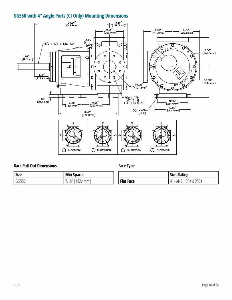
GG550 with 4” Angle Ports (CI Only) Mounting Dimensions
Back Pull-Out Dimensions
Size Min SpacerGG550 7.18" [182.4mm]
Face Type
Size-RatingFlat Face 4" - ANSI 125# & 250#

Page 19 of 36V 1.29
Pos. 1 & 2 - Pump SeriesGG = complete pumpGD = drive module
Pos. 3, 4, & 5 - Pump Size015 = nominal 15 GPM at 1800 RPM030 = nominal 30 GPM at 1800 RPM050 = nominal 50 GPM at 1500 RPM070 = nominal 70 GPM at 1500 RPM080 = nominal 80 GPM at 1500 RPM090 = nominal 90 GPM at 1500 RPM120 = nominal 120 GPM at 1200 RPM130 = nominal 130 GPM at 1000 RPM200 = nominal 200 GPM at 1000 RPM210 = nominal 210 GPM at 800 RPM250 = nominal 200 GPM at 640 RPM550 = nominal 550 GPM at 500 RPM
Pos. 6 - Material of ConstructionI = ironS = stainless steelC = cast steel
Pos. 7 - Port Position & Rotation
A-ROTATION B-ROTATION
D-ROTATION E-ROTATION F-ROTATION
C-ROTATION
Pos. 8 - Relief Valve0 = noneV = internal
Pos. 9 - Sealing MethodP = packingI = IB mechanical seal (behind rotor)M = OB mechanical seal (in stuffing box)C = cartridge mechanical seal
Pos. 10 - Seal Type0 = no gland or packingA = standard packing (graphite/PTFE)**B = NI Resistant Type 2 Mechanical SealC = food-grade packing (pure PTFE)E = Viton mechanical sealF = PTFE mechanical sealH = abrasion-resistant mech. seal (Viton)L = gen. purp. single cartridge seal (<7,500 SSU)M = hard face cartridge sealN = process single cartridge seal (<75,000 SSU)Q = Heavy Duty Slurry (Viton) R = Heavy Duty Slurry (Chemraz)T = TuffSeal cartridge lip seal (Viton O-rings)K = Triple Lip - PMF PTFE - VitonP = Hard Faces Cartridge Single Mech. Seal (Tungsten Carbide/Silicar - Viton) Quench Drain
Pos. 11 - Seal Flush0 = none 1 = internal vent to suction (Plan 13)
Pos. 12 - Port Type0 = none A = FNPT C = ANSI 125# flanged (C.I. only)D = ANSI 150# flangedE = ANSI 250# flanged (C.I. only)F = ANSI 300# flanged
Pos. 13 - Port Size0 = noneH = 1-1/2” or 40mmI = 2” or 50mmJ = 2-1/2” or 65mmK = 3” or 80mmL = 4” or 100mmN = 6” or 150mm
Pos. 14 - Shaft DimensionsI = Inch seal & coupling
Pos. 15 - Bushings & PinA = bronze idler & bracketC = carbon idler, bronze bracketD = carbon idler & bracketE = hi-temp carbon idler & bracketG = T.C. idler with T.C. pin, bronze bracketI = T.C. idler & bracket with T.C. pin & hardened
shaft
Pos. 16 - Tutriding0 = none1 = Tutrided rotor head, idler, cover2 = Tutrided rotor head, idler, cover, housing
Pos. 17 - Jackets0 = none1 = cover only2 = bracket only3 = cover and bracket
Pos. 18 - Clearances0 = standard <7,500 SSU, -100° to 200°FA = 7,500 to 75,000 SSU 200° to 300°FB = 75,000 to 750,000 SSUG = <7,500 SSU 300°F to 450°F (see note)H = 450°F to 550°F (see note)J = Chocolate Clearance Mods (Include Class B Clearance, Bronze Bushings, Root Drilled Idler & Drilled Rotor Head.)
Note: Pumps with G or H in this position include hi-temp package (paint, bearing & gaskets)
Legendn = NOT AVAILABLE ON ALL SIZES C.I. = Cast IronT.C. = Tungsten Carbide
Pum
p Se
ries
Pum
p Siz
e
Mat
eria
l of
Cons
truct
ion
Port
Posit
ion
& Ro
tatio
n
Relie
f Val
ve
Seal
ing
Met
hod
Seal
ing
Type
Seal
Flus
h
Port
Type
Port
Size
Shaf
t Di
men
sions
Bush
ing
Pin
Tutri
ding
Jack
ets
Clea
ranc
es
G G 2 1 0 I A V M A 1 A K I A 0 0 0Position 1 2 3 4 5 6 7 8 9 10 11 12 13 14 15 16 17 18
GlobalGear® Model Number System
For Special Pumps with a Feature not Described Below
Pump Series Pump Size Material Port Orientation Special Indicator Year of Design Sequential Special Number
GG 210 I A - X 01 56

Page 20 of 36V 1.29
GlobalGear® Material of Construction
Size Port CI CS SS HG CD
015Angle X X X XSide X X X X
030Angle X X X XSide X X X X X
050Angle X X XSide X X X
070Angle X X XSide X X X
080Angle X X X XSide X X X X
090Angle X X XSide X X X
120Angle X X XSide X X X
130Angle X X X XSide X X X X X
200Angle X X XSide X X X
210Angle X X X XSide X X X X
250Angle X X X XSide X X X X X
550Angle X X X XSide X X X X X
CI = Cast Iron CS = Cast Steel SS = Stainless Steal HG = Heavy Gear CD = Compressor Duty

Page 21 of 36V 1.29
GlobalGear® Clearance Viscosity LimitsVi
scos
ity SS
U 750,000 B B B B B B B75,000 A A A A A A A7,500 O O O O O O O O O O O O
0 015 030 050 070 080 090 120 130 200 210 250 550
GlobalGear® Temperature Limits
°F Clearances Pump Series Bushings Seal Elastomers Packing HT Opts °C600
Cast
Iron C
onstr
uctio
n
Cast
Steel
Cons
tructi
on
HT Ca
rbon
Bush
ings
HT Ba
ll Bea
ring,
Gask
ets, a
nd Pa
int
316550
Class
H
Stand
ard P
ackin
g (PT
FE/G
raph
ite)
288
500
Stainl
ess S
teel C
onstr
uctio
n
HT Tu
ngste
n Car
bide B
ushin
g (CI)
260475°F
450
Class
G
Bron
ze Bu
shing
s232
400Sta
ndar
d Car
bon B
ushin
gs
PTFE
(See
Note
3)
204
390 199
380 193
370 188
365Vit
on185
360 182350 177
300
Class
A
HT TC
Bu
shs (
SS)
Stand
ard B
all Be
aring
, Gas
kets,
and P
aint
149
250 121
200
Class
0
Std. T
ungs
ten Ca
rbide
Bush
ings (
CI)
Std. T
ungs
ten Ca
rbide
Bush
ing (S
S)
93150 66100 38
50 100 -18
-10 -23-20 -29-30 -34-40 -40-50 -46
-100 -73
Notes: 1. A pump’s performance is dependent on more than just the temperature ranges of the component materials. 2. Pumps with extra clearances may have reduced flow rates when operated at lower temperatures. 3. Pumps with PTFE seals also have PTFE-encapsulated Viton O-rings which are limited to 400 °F (204 °C). Clearance Class J = Chocolate Clearance Mods (Include Class B Clearance, Bronze Bushings, Root Drilled Idler & Drilled Rotor Head.)

Page 22 of 36V 1.29
GlobalGear® Materials of Construction
Part Name Material Standard CommentsAvailability Compressor
DutyGGI GGS* GGC*
Housing, Cover
cast iron (CI) ASTM A48 S STutrided CI ASTM A48 surface hardened Ostainless steel (SS) ASTM A743, grade CF8M cast version of 316 SS Scast steel (CS) ASTM A216, grade WCB S O
Bracket, Valve Body
cast iron (CI) ASTM A48 S Sstainless steel (SS) ASTM A743, grade CF8M cast version of 316 SS Scast steel (CS) ASTM A216, grade WCB S
Valve Block-Off Plate
steel AISI 1018 no contact with pumpage S* S S
Rotor Head, Idler Gear
ductile iron (DI) ASTM A536, grade 80-55-06 S S STutrided DI ASTM A536, grade 80-55-06 surface hardened O Ostainless steel (SS) ASTM A494, grade CY5SnBiM "Nitronic 60" S
Rotor Shaft
carbon steel (CS) AISI 4140 S Shardened steel AISI 4140 induction hardened O O Sstainless steel (SS) ASTM A564, grade 630 "Armco 17-4PH" Shard-coated SS ASTM A564, grade 630 chrome oxide coated O
Idler Pinhardened steel AISI 1117 case hardened S Sstainless steel (SS) ASTM A564, grade 630 "Armco 17-4PH" O Stungsten carbide grade C2 O O O
Bushings
bronze SAE CA932 Sstandard carbon carbon graphite resin O S S Shigh-temp carbon carbon graphite O O Otungsten carbide grade C2 O O O
Gasketsstandard fiber with nitrile binder "Garlock" Style 3000 Shigh-temp graphite/316 SS "Garlock" Style 3125TC/
SS O S S
Bearing Carrier cast iron (CI) ASTM A48 no contact with pumpage S S SCover Jacket ductile iron (DI) ASTM A536, grade 80-55-06 no contact with pumpage O O
Jacketed Bracketcast iron (CI) ASTM A48 O*stainless steel (SS) ASTM A276, grade 316 O
Availability Codes Pump ModelsS= Standard material for this pump series GGI= GlobalGear®, IronO= Optional material for this pump series GGS= GlobalGear®, Stainless Steel* Not available with GG550 pumps GGC= GlobalGear®, Cast SteelRelief valves not available with GG550 angle ported pumps Compressor Duty: Stadard Viton O-ring

Page 23 of 36V 1.29
GlobalGear® Standard Seal Specifications (GG015 – GG030)
Mechanical Seals for 1 1/8” Shaft
Seal Description Part Number Vendor Seal Type
Material of ConstructionSecondary
SealRotary Face
Stationary Face
Wetted Hardware
(E) Viton Mechanical Seal (Viton, carbon vs. ceramic) G015UI9-21-E FC 21 Viton® Carbon Ceramic 304 S.S.
(F) PTFE Mechanical Seal (PTFE, carbon vs. ceramic) G015UI9-9T-F FC 9T PTFE Carbon Ceramic 304 S.S.
(H)Abrasion-Resistant Mech Seal (Viton, SiC vs. SiC) G015UI9-31-H FC 31 Viton Silicon
CarbideSilicon
Carbide 304 S.S.
(L) General Purpose Single Cartridge Mech. Seal G015UI9-91GP-L FC 91 Viton Silicon
Carbide Carbon 302 S.S.
(T) Cartridge Lip Seal G015UI9-4422-T FC 122 Viton Silicon Carbide Filled PTFE 316 S.S.
(Q) Heavy Duty Slurry Seal (Viton) G015UI9-FLDL-82 FC 82 Viton Tungsten Carbide
Silicon Carbide 416 S.S.
(R) Heavy Duty Slurry Seal (Chemraz) G015UI9-FLDL-82C FC 82 Chemraz Tungsten Carbide
Silicon Carbide 416 S.S.
(P) Hard Face Cartridge Single Seal TC vs. SiC Faces, Viton, & Quench Gland G015UI9-5610-P FC 5610 Viton Tungsten
CarbideSilicon
Carbide 316 S.S.
Packing Description Part Number Vendor Packing Style Material Description(A) Standard Packing (graphite/PTFE) G015II94 FC ML4002 or ML8002 Braided PTFE with graphite impregnation.(C) Food-Grade Packing (PTFE) G015II94-FG FC ML2236FDA Braided pure PTFE. FDA approved.
Viton®-Registered trademark of DuPont De Nemours & Company/Gylon®-Registered trademark of Garlock, Inc./FC=Factory Choice (Flowserve, Fluidol, John Crane, Sepco)

Page 24 of 36V 1.29
Mechanical Seals for 28mm Shaft
Seal Description Part number Vendor Seal Type
Material of ConstructionSecondary
SealRotary Face
Stationary Face Hardware
(E) Viton Mechanical Seal (Viton, carbon vs. ceramic) G015UM9-21-E FC 52 Viton Carbon Silicon
Carbide 316 S.S.
(F) PTFE Mechanical Seal (PTFE, carbon vs. ceramic) G015UM9-9T-F FC 9T PTFE Carbon Silicon
Carbide 316 S.S.
(H) Abrasion-Resistant Mech. Seal (Viton, SiC vs. SiC) G015UM9-31-H FC 52 Viton Silicon
CarbideSilicon
Carbide 316 S.S.
(I) Viton Cartridge Single Mech. Seal (Viton, carbon vs. silicon carbide) G015UM9-ISC-I FC ISC1PX Viton Carbon Silicon
Carbide 316 S.S.
(J) Viton Cartridge Double Mech. Seal (Viton, carbon vs. silicon carbide) G015UM9-ISC-J FC ISCX2PP Viton Carbon Silicon
Carbide 316 S.S.
(K) Triple Lip Cartridge Seal G015UM9-PSII-K FC P/S-II Viton Gylon (lip seals)
Silicon Carbide 316 S.S.
Packings for 1 1/8” (or 28mm) Shaft
Packing Description Part number Vendor Packing Style Material Description(A) Standard Packing (graphite/PTFE) G015UU94 FC ML4002 or ML8002 Braided PTFE with graphite impregnation.(C) Food-Grade Packing (PTFE) G015UU94-FG FC ML2236FDA Braided pure PTFE. FDA approved.
Viton®-Registered trademark of DuPont De Nemours & Company/Gylon®-Registered trademark of Garlock, Inc./FC=Factory Choice (Flowserve, Fluidol, John Crane, Sepco)

Page 25 of 36V 1.29
GlobalGear® Standard Seal Specifications (GG050 – GG090)
Mechanical Seals for 1 3/8” Shaft
Seal Description Part Number Vendor Seal Type
Material of ConstructionSecondary
SealRotary Face
Stationary Face
Wetted Hardware
(E) Viton Mechanical Seal (Viton, carbon vs. ceramic) G050UI9-21-E FC 21 Viton Carbon Ceramic 304 S.S.
(F) PTFE Mechanical Seal (PTFE, carbon vs. ceramic) G050UI9-9T-F FC 9T PTFE Carbon Ceramic 304 S.S.
(H) Abrasion-Resistant Mech Seal (Viton, SiC vs. SiC) G050UI9-31-H FC 31 Viton Silicon
CarbideSilicon
Carbide 304 S.S.
(L) General Purpose Single Cartridge Mech. Seal G050UI9-91GP-L FC 91 Viton Silicon
Carbide Cardon 302 S.S.
(T) Cartridge Lip Seal G050UI9-4422-T FC 122 Viton Silicon Carbide Filled PTFE 316 S.S.
(Q) Heavy Duty Slurry Seal (Viton) G050UI9-FLDL-82 FC 82 Viton Tungsten Carbide
Silicon Carbide 416 S.S.
(R) Heavy Duty Slurry Seal (Chemraz) G050UI9-FLDL-82C FC 82 Chemraz Tungsten Carbide
Silicon Carbide 416 S.S.
(P) Hard Face Cartridge Single Seal TC vs. SiC Faces, Viton, & Quench Gland G050UI9-5610-P FC 5610 Viton Tungsten
CarbideTungsten Carbide 316 S.S.
Lips Sleeve Hardware
(K) Triple Lip PMF-PTFE Viton G050UI9-4232-K FC 42 Viton Filled PTFE
Tungsten Carbide 316 S. S.
Packing Description PartNumber Vendor Packing Style Material Description(A) Standard Packing (graphite/PTFE) G050II94 FC ML4002 or ML8002 Braided PTFE with graphite impregnation.(C) Food-Grade Packing (PTFE) G050II94-FG FC ML2236FDA Braided pure PTFE. FDA approved.
Viton®-Registered trademark of DuPont De Nemours & Company/Gylon®-Registered trademark of Garlock, Inc./FC=Factory Choice (Flowserve, Fluidol, John Crane, Sepco)

Page 26 of 36V 1.29
GlobalGear® Standard Seal Specifications (GG120 – GG250)
Mechanical Seals for 1 3/4” Shaft
Seal Description Part Number Vendor Seal Type
Material of ConstructionSecondary
SealRotary Face
Stationary Face
Wetted Hardware
(E) Viton Mechanical Seal (Viton, carbon vs. ceramic) G120UI9-21-E FC 21 Viton® Carbon Ceramic 304 S.S.
(F) PTFE Mechanical Seal (PTFE, carbon vs. ceramic) G120UI9-9T-F FC 9T PTFE Carbon Ceramic 304 S.S.
(H)Abrasion-Resistant Mech Seal (Viton, SiC vs. SiC) G120UI9-31-H FC 31 Viton Silicon
CarbideSilicon
Carbide 304 S.S.
(L) General Purpose Single Cartridge Mech. Seal G120UI9-91GP-L FC 91 Viton Silicon
Carbide Carbon 302 S.S.
(T) Cartridge Lip Seal G120UI9-4422-T FC 122 Viton Silicon Carbide Filled PTFE 316 S.S.
(Q) Heavy Duty Slurry Seal (Viton) G120UI9-FLDL-82 FC 82 Viton Tungsten Carbide
Silicon Carbide 416 S.S.
(R) Heavy Duty Slurry Seal (Chemraz) G120UI9-FLDL-82C FC 82 Chemraz Tungsten Carbide
Silicon Carbide 416 S.S.
(P) Hard Face Cartridge Single Seal TC vs. SiC Faces, Viton, & Quench Gland G120UI9-5610-P FC 5610 Viton Tungsten
CarbideSilicon
Carbide 316 S.S.
Lips Sleeve Hardware
(K) Triple Lip PMF-PTFE Viton G120UI9-4232-K FC 42 Viton Filled PTFE
Silicon Carbide 316 S. S.
Packing Description PartNumber Vendor Packing Style Material Description(A) Standard Packing (graphite/PTFE) G120II94 FC ML4002 or ML8002 Braided PTFE with graphite impregnation.(C) Food-Grade Packing (PTFE) G120II94-FG FC ML2236FDA Braided pure PTFE. FDA approved.
Viton®-Registered trademark of DuPont De Nemours & Company/Gylon®-Registered trademark of Garlock, Inc./FC=Factory Choice (Flowserve, Fluidol, John Crane, Sepco)

Page 27 of 36V 1.29
GlobalGear® Standard Seal Specifications (GG550)
Mechanical Seals for 2 3/4” Shaft
Seal Description Part Number Vendor Seal Type
Material of ConstructionSecondary
SealRotary Face
Stationary Face
Wetted Hardware
(F) PTFE Mechanical Seal (PTFE, carbon vs. ceramic) G500UI9-9T-F FC 9T PTFE Carbon Ceramic 316 S.S.
(L) General Purpose Single Cartridge Mech. Seal G500UI9-4610-L FC 4610 Viton Carbon Silicon
Carbide 316 S.S.
(T) Cartridge Lip Seal G500UI9-4422-T FC 122 Viton Silicon Carbide Filled PTFE 316 S.S.
(Q) Heavy Duty Slurry Seal (Viton) G500UI9-FLDL-82 FC 82 Viton Tungsten Carbide
Silicon Carbide 416 S.S.
(P) Hard Face Cartridge Single Seal TC vs. SiC Faces, Viton, & Quench Gland G500UI9-5610-P FC 5610 Viton Tungsten
CarbideSilicon
Carbide 316 S.S.
Lips Sleeve Hardware
(K) Triple Lip PMF-PTFE Viton G500UI9-4232-K FC 42 Viton Filled PTFE
Silicon Carbide 316 S.S.
Packing Description PartNumber Vendor Packing Style Material Description(A) Standard Packing (graphite/PTFE) G500II94 FC ML4002 or ML8002 Braided PTFE with graphite impregnation.(C) Food-Grade Packing (PTFE) G500II94-FG FC ML2236FDA Braided pure PTFE. FDA approved.
Viton®-Registered trademark of DuPont De Nemours & Company/Gylon®-Registered trademark of Garlock, Inc./FC=Factory Choice (Flowserve, Fluidol, John Crane, Sepco)

Page 28 of 36V 1.29
GlobalGear® Seal Chamber Dimensions Mech Seal (Inboard Location, Inch Shaft)
Dimension GG015/030 "GG050/070/080/090" GG120/130 GG200/210/250 GG550Shaft Diameter - 1.125" 1.375" 1.75" 1.75"
N/A
Chamber Diameter D1 2.000" 2.313" 2.750" 2.750"Seal Working Length(std. gland) L1 1.490" 1.562" 1.875" 1.875"
Seal Working Length (opt. gland) L1 1.440" 1.812" n/a n/a
Seat Bore Diameter D2 1.75" 2.000" 2.500" 2.500"Seat Bore Length (min) L2 0.437 0.398" 0.50" 0.50"
Optional Gland PinD3 0.125" 0.125" 0.125" 0.125"R3 0.75" 0.86" 1.17" 1.17"H3 0.08" 0.08 0.18" 0.18"
D3
INBOARDGLAND
D2
L1
L2
H3
D1 R3

Page 29 of 36V 1.29
GlobalGear® Seal Chamber Dimensions Mech Seal (Outboard Location, Inch Shaft)
Dimension GG15/30 "GG50/70/80/90" GG120/130 GG200/210/250 GG550Shaft Diameter - 1.125" 1.375" 1.750" 1.750" 2.75"Bolt Size - 4 x M10 2 x M10 2 x M12 2 x M12 2 x M12Bolt Circle - 3.13" 3.35" 4.25" 4.25" 5.90"Chamber Diameter D1 2.000" 2.313" 2.750" 2.750" 4.50"Seal Working Length (std. gland) L1 1.490" 1.562" 1.860" 1.860" 2.630"
Seal Working Length (opt. gland) L1 1.440" 1.812" n/a n/a n/a
Seat Bore Diameter D2 1.750" 2.000" 2.500" 2.500" 3.500"Seat Bore Length (min.) L2 0.616" 0.437" 0.50" 0.50" 0.55"
Optional Gland PinD3 0.125" 0.125" 0.125" 0.125" 0.125"R3 0.75" 0.86" 1.13" 1.13" 1.54"H3 0.08" 0.08" 0.12" 0.12" 0.094"
Chamber Depth to Pin Hole L3 1.26" 1.77" 1.89" 1.89" n/a
Pin Hole Dia. D4 0.13" 0.13" 0.13" 0.13" n/a
H3D1
R3 BOLTCIRCLED2
L2
BOLT SIZE
L1
D3
D4L3

Page 30 of 36V 1.29
GlobalGear® Seal Chamber Dimensions Packing
Dimension (Inch Shaft) GG15/30 "GG50/70/80/90" GG120/130 GG200/210/250 GG550Shaft Diameter - 1.125" 1.375" 1.750" 1.750" 2.75"Bolt Size - 4 x M10 2 x M10 2 x M12 2 x M12 2 x M12Bolt Circle - 3.13" 3.35" 4.25" 4.25" 5.90"Chamber Diameter D1 2.000" 2.313" 2.750" 2.750" 3.78"Chamber Length W1 1.69" 2.22" 2.43" 2.43" 2.95"Gland Length W3 0.64" 0.82" 0.68" 0.68" 1.14"
D1
BOLT SIZE
W1
W3
BOLTCIRCLE

Page 31 of 36V 1.29
GlobalGear® Seal Chamber Dimensions Cartridge Seal
Dimension (Inch Shaft) GG15/30 "GG50/70/80/90" GG120/130 GG200/210/250 GG550Shaft Diameter - 1.125" 1.375" 1.750" 1.750" 2.750"Bolt Size - 4 x M10 2 x M10 2 x M12 2 x M12 2 x M14Bolt Circle - 3.13" 3.35" 4.25" 4.25" 5.906"Chamber Diameter D1 2.000" 2.313" 2.750" 2.750" 3.78"Chamber Length W1 1.69" 2.22" 2.43" 2.43" 2.95"Max Seal Diameter D4 3.75" 4.88" 5.60" 5.75" -----Max Seal Length L4 2.95" 2.62" 4.40" 4.40" 4.66Gland Obstruction Diameter D6 2.87" 4.56" 5.65" 5.75" -----
Gland Obstruction Length L6 0.25" 0.25" 0.44" 0.44" -----
Chamber Depth to Pin Hole L7 1.26" 1.77" 1.89" 1.89" -----
Pin Hole Dia. D7 0.13" 0.13" .13" .13" -----
D6D4
L6
BOLT SIZE
L4
D1 BOLTCIRCLE
L7D7
W1

Page 32 of 36V 1.29
GlobalGear® Jackets Data & Dimensions
AD (3 Ports)AC AB
AE AF (2 Ports)
Dimensions - 90° Ports
Pump SizeJacketed Cover Jacketed Bracket
AB AEAF
ACAD
inch mm inch mm inch mmGG15/30 IB seal 3.67 93 2.04 52 1/2" NPT 3.58 91 3/8" NPT
GG15/30 OB seal 3.67 93 2.04 52 1/2" NPT 2.93 74 One - 3/8” NPTTwo - 1/4-18 NPT
GG120/130 4.37 111 4.72 120 3/4" NPT 4.93 125 1" NPTGG200/210 5.31 135 6.14 156 3/4" NPT 5.62 143 1" NPTGG250 5.31 135 6.14 156 3/4" NPT 5.62 143 1" NPTGG550 8.49 216 9.45 240 3/4" NPT N/A N/A N/A
Jacket Ratings Steam Heat Transfer FluidMax Temperature ° F 365 600
° C 185 316Max Pressure psig 150 150
bar g 10.3 10.3
Notes: Jacketed covers are not available with pumps with relief valves. Brackets also contain additional ports that access the seal chamber. Do not connect them to steam or H.T.F.

Page 33 of 36V 1.29
GlobalGear® Jackets Data & Dimensions
AD (3 Ports)AC AB AF (2 Ports)
AE
Dimensions - 180° Ports
pump sizeJacketed Cover Jacketed Bracket
AB AEAF
ACAD
inch mm inch mm inch mmGG15/30 IB seal 3.17 81 2.04 52 1/2" NPT 4.08 104 3/8" NPTGG15/30 OB seal 3.17 81 2.04 52 1/2" NPT 4.08 104 3/8" NPTGG120/130 4.37 111 4.72 120 3/4" NPT 4.37 111 1" NPTGG200/210 5.65 144 6.14 156 3/4" NPT 5.33 135 1" NPTGG250 5.65 144 6.14 156 3/4" NPT 5.33 135 1" NPTGG500 8.49 216 9.45 240 3/4" NPT N/A N/A N/A
Jacket Ratings Steam Heat Transfer FluidMax Temperature ° F 365 600
° C 185 316Max Pressure psig 150 150
bar g 10.3 10.3
Notes: Jacketed covers are not available with pumps with relief valves. Brackets also contain additional ports that access the seal chamber. Do not connect them to steam or H.T.F.

Page 34 of 36V 1.29
GlobalGear® NPSH Data
NPSHr for up to 750 ssu (Feet of Water)
Size 150 rpm 250 rpm 350 rpm 450 rpm 550 rpm 750 rpm 950 rpm 1150 rpm 1450 rpm 1750 rpmGG015 1.4 1.6 1.8 2.1 2.4 3.0 4.5 6.2 8.6 11.3GG030 1.4 1.6 1.8 2.1 2.4 3.0 4.5 6.2 8.6 11.3GG050 1.5 1.8 2.2 2.7 3.4 5.2 7.7 11.2 15.0GG070 1.5 1.8 2.2 2.7 3.4 5.2 7.7 11.2 15.0GG080 1.5 1.8 2.2 2.7 3.4 5.2 7.7 11.2 15.0GG090 1.5 1.8 2.2 2.7 3.4 5.2 7.7 11.2 15.0GG120 1.6 1.9 2.7 3.5 4.7 7.7 11.7 16.4GG130 1.6 1.9 2.7 3.5 4.7 7.7 11.7GG200 1.8 2.4 3.6 4.8 6.9 11.9 17.4GG210 1.8 2.4 3.6 4.8 6.9 11.9GG250 1.8 2.4 3.6 4.8 6.9 11.9GG550 3.4 6.2 10.5 15.8 24.0
NPSHr for up to 165 cst. (Meters of Water)
Size 150 rpm 250 rpm 350 rpm 450 rpm 550 rpm 750 rpm 950 rpm 1150 rpm 1450 rpm 1750 rpmGG015 0.4 0.5 0.5 0.6 0.7 0.9 1.4 1.9 2.6 3.4GG030 0.4 0.5 0.5 0.6 0.7 0.9 1.4 1.9 2.6 3.4GG050 0.5 0.5 0.7 0.8 1.0 1.6 2.3 3.4 4.6GG070 0.5 0.5 0.7 0.8 1.0 1.6 2.3 3.4 4.6GG080 0.5 0.5 0.7 0.8 1.0 1.6 2.3 3.4 4.6GG090 0.5 0.5 0.7 0.8 1.0 1.6 2.3 3.4 4.6GG120 0.5 0.6 0.8 1.1 1.4 2.3 3.6 5.0GG130 0.5 0.6 0.8 1.1 1.4 2.3 3.6GG200 0.5 0.7 1.1 1.5 2.1 3.6 5.3GG210 0.5 0.7 1.1 1.5 2.1 3.6GG250 0.5 0.7 1.1 1.5 2.1 3.6GG550 1.0 1.9 3.2 4.8 7.3
High Viscosity Correction Factors
Viscosity CF Viscosity CF Viscosity CF2500 ssu / 550 cst 1.3 25,000 ssu / 5500 cst 2.7 250,000 ssu / 55,000 cst 5.35000 ssu / 1100 cst 1.7 50,000 ssu / 11,000 cst 3.1 500,000 ssu / 110,000 cst 6.710,000 ssu / 2200 cst 2.0 100,000 ssu / 22,000 cst 4.0 1,000,000 ssu / 220,000 cst 10.7
Notes: For viscosity above 750 ssu (165 cst), multiply the charted NPSHr value by the appropriate correction factor. NPSHa (available) must be greater than NPSHr (required) for proper pump operation. Data shown here is for pumps with standard ports. Optional ports of different sizes may affect NPSHr.

Page 35 of 36V 1.29
GlobalGear® Flange Ratings (Cast Iron)
ANSI 125#
ANSI 250#
0
100
200
300
-50 0 50 100 150 200 250 300 350 400 450 500 550 6000
10
20-45 5 55 105 155 205 255 305
Temperature (°C)
Temperature (°F)
Pressure (PSIG) Pressure (bar g)
Note: These charts show the ratings for flanges only - the maximum pump operating conditions must also be checked. Consult the appropriate Tuthill catalog for maximum allowable operating pressures and temperatures, based on pump application conditions and pump features. These ratings are based on non-shock pressures. ANSI data is from ASME/ANSI B16.1 - 1989 (class A). Consult this spec for more information. ISO data is from ISO 7005-2 : 1988 (gray iron). Consult this spec for more information.
GlobalGear® Flange Ratings (Stainless Steel)
ANSI 150#
0
100
200
300
-50 0 50 100 150 200 250 300 350 400 450 500 550 6000
10
20
-45 5 55 105 155 205 255
Temperature (°C)
Temperature (°F)
Pressure (PSIG) Pressure (bar g)
Note: These charts show the ratings for flanges only - the maximum pump operating conditions must also be checked. Consult the appropriate Tuthill catalog for maximum allowable operating pressures and temperatures, based on pump application conditions and pump features. These ratings are based on non-shock pressures. ANSI data is from ASME/ANSI B16.5 - 1988 (matl group 2.2). Consult this spec for more information. ISO data is from ISO 7005-1 : 1992 (matl group 13E0). Consult this spec for more information.

Tuthill Pump GroupUSA • United Kingdom • Chinawww.tuthillpump.com
Excellence at work. Excellence in life.
GG Series Pumps Nozzle Loading Data
Nominal Port Size Max. Fx, Fy & Fz Max. Mx, My, & MzPump Size Inch mm Lbs. N Lb-ft. N-m
GG015-0301.5 40 113 500 188 2552 50 150 667 250 339
GG050-070 2 50 150 667 250 339
GG080-0902 50 150 667 250 3393 80 225 1001 375 508
GG120-130
2 50 150 667 250 3392.5 65 150 667 312 4243 80 225 1001 375 5084 100 300 1334 500 678
GG200-210-250
2 50 150 667 250 3392.5 65 150 667 312 4243 80 225 1001 375 5084 100 300 1334 500 678
GG550 6 150 450 2002 750 1017
Notes: We always recommend proper pipe support. Hydraulic Institute standards state, “… both suction and discharge piping should be independently supported near the pump so that when the flange bolts are tightened, no strain will be transmitted to the pump casing.” For GG Iron Series, multiply the above values by 0.35. These maximum values are not valid for combined forces and moments.