Embed Size (px)
Citation preview
1
Engineering a Multimission Approach to Navigation Ground Data System Operations
Dimitrios V. Gerasimatos* and Ahlam A. Attiyah† Jet Propulsion Laboratory, California Institute of Technology, Pasadena, CA 91109
The Mission Design and Navigation (MDNAV) Section at the Jet Propulsion Laboratory (JPL) supports many deep space and earth orbiting missions from formulation to end of mission operations. The requirements of these missions are met with a multimission approach to MDNAV ground data system (GDS) infrastructure capable of being shared and allocated in a seamless and consistent manner across missions. The MDNAV computing infrastructure consists of compute clusters, network attached storage, mission support area facilities, and desktop hardware. The multimission architecture allows these assets, and even personnel, to be leveraged effectively across the project lifecycle and across multiple missions simultaneously. It provides a more robust and capable infrastructure to each mission than might be possible if each constructed its own. It also enables a consistent interface and environment within which teams can conduct all mission analysis and navigation functions including: trajectory design; ephemeris generation; orbit determination; maneuver design; and entry, descent, and landing analysis. The savings of these efficiencies more than offset the costs of increased complexity and other challenges that had to be addressed: configuration management, scheduling conflicts, and competition for resources. This paper examines the benefits of the multimission MDNAV ground data system infrastructure, focusing on the hardware and software architecture. The result is an efficient, robust, scalable MDNAV ground data system capable of supporting more than a dozen active missions at once.
I. Introduction N 1992, the National Aeronautics and Space Administration (NASA) began an initiative towards a greater number of less expensive missions instead of fewer costly flagship missions such as the Cassini mission to Saturn.1 The
lower cost of these missions was achieved in many ways: producing smaller, less complex spacecraft with fewer instruments and single-string designs; utilizing smaller launch vehicles; implementing faster development cycles; and deploying smaller development and operations teams.2
In the two decades since, NASA has continued to transition from a few high cost missions to many lower cost missions requiring more project teams, better methods, and more productivity supported by multimission technology and standardization.3 Mission operations teams shifted from being large teams each dedicated to support a single mission to smaller, more dynamic teams comprising individuals supporting multiple missions simultaneously. Navigators transitioned from supporting no more than a few missions at time to working concurrently on multiple projects of varying complexity including planetary missions, Earth-orbiting satellites and launches by foreign governments.4 In 2003, in response to the increasing need to support many missions at once, the MDNAV Section transitioned to a more multimission approach to navigation development and operations. A navigation ground data system infrastructure was designed and developed to support this approach. This approach has met with much success as * Systems Administrator, Mission Design and Navigation Section, M/S: 264-282, 4800 Oak Grove Dr., AIAA Senior Member † Group Supervisor, Mission Design and Navigation Section, Mail Stop 301-121, 4800 Oak Grove Dr. ©2012 California Institute of Technology. Government sponsorship acknowledged.
I
2
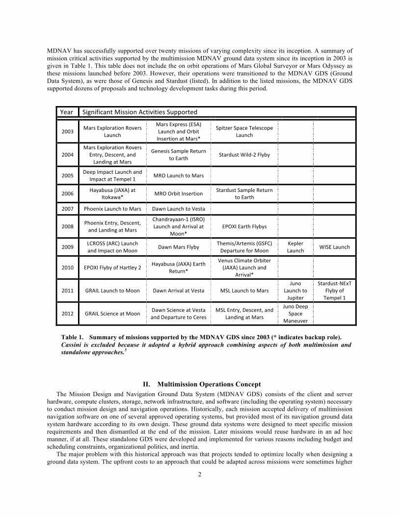
MDNAV has successfully supported over twenty missions of varying complexity since its inception. A summary of mission critical activities supported by the multimission MDNAV ground data system since its inception in 2003 is given in Table 1. This table does not include the on orbit operations of Mars Global Surveyor or Mars Odyssey as these missions launched before 2003. However, their operations were transitioned to the MDNAV GDS (Ground Data System), as were those of Genesis and Stardust (listed). In addition to the listed missions, the MDNAV GDS supported dozens of proposals and technology development tasks during this period.
II. Multimission Operations Concept The Mission Design and Navigation Ground Data System (MDNAV GDS) consists of the client and server hardware, compute clusters, storage, network infrastructure, and software (including the operating system) necessary to conduct mission design and navigation operations. Historically, each mission accepted delivery of multimission navigation software on one of several approved operating systems, but provided most of its navigation ground data system hardware according to its own design. These ground data systems were designed to meet specific mission requirements and then dismantled at the end of the mission. Later missions would reuse hardware in an ad hoc manner, if at all. These standalone GDS were developed and implemented for various reasons including budget and scheduling constraints, organizational politics, and inertia.
The major problem with this historical approach was that projects tended to optimize locally when designing a ground data system. The upfront costs to an approach that could be adapted across missions were sometimes higher
Year Significant Mission Activities Supported
2003 Mars Exploration Rovers Launch
Mars Express (ESA) Launch and Orbit Insertion at Mars*
Spitzer Space Telescope Launch
2004 Mars Exploration Rovers
Entry, Descent, and Landing at Mars
Genesis Sample Return to Earth Stardust Wild-‐2 Flyby
2005 Deep Impact Launch and Impact at Tempel 1 MRO Launch to Mars
2006 Hayabusa (JAXA) at Itokawa* MRO Orbit Insertion Stardust Sample Return
to Earth
2007 Phoenix Launch to Mars Dawn Launch to Vesta
2008 Phoenix Entry, Descent, and Landing at Mars
Chandrayaan-‐1 (ISRO) Launch and Arrival at
Moon* EPOXI Earth Flybys
2009 LCROSS (ARC) Launch and Impact on Moon Dawn Mars Flyby Themis/Artemis (GSFC)
Departure for Moon Kepler Launch WISE Launch
2010 EPOXI Flyby of Hartley 2 Hayabusa (JAXA) Earth Return*
Venus Climate Orbiter (JAXA) Launch and
Arrival*
2011 GRAIL Launch to Moon Dawn Arrival at Vesta MSL Launch to Mars Juno
Launch to Jupiter
Stardust-‐NExT Flyby of Tempel 1
2012 GRAIL Science at Moon Dawn Science at Vesta and Departure to Ceres
MSL Entry, Descent, and Landing at Mars
Juno Deep Space
Maneuver
Table 1. Summary of missions supported by the MDNAV GDS since 2003 (* indicates backup role). Cassini is excluded because it adopted a hybrid approach combining aspects of both multimission and standalone approaches.5

3
than a design that met only the requirements of a particular mission. There was little incentive to consider overall cost to JPL (Jet Propulsion Laboratory) or NASA. Although software was designed to be multimission in nature, the reuse, inheritance, and standardization of GDS hardware was often not a consideration to the design. If new missions did decide to cut costs by inheriting hardware from previous missions, there was no established mechanism other than informal agreements between projects. Even with an agreement, missions could not guarantee that hardware would be available to be reused by future missions when needed. For example, even though the Mars Reconnaissance Orbiter (MRO) was designed to carry enough propellant to remain operational for 5 years beyond the end-of-mission (EOM), the nominal EOM date was December 31, 2010.6 Its mission has since been extended until September 2012 and it is expected to stay on-orbit for many years to come.7 Any mission that was planning to inherit MRO GDS hardware after EOM would have found itself having to make alternate plans. Moreover, missions like the Mars Exploration Rover (MER) Opportunity, which exceeded its design lifetime by a factor of more than 30, might be expected to make costly unplanned investments in infrastructure to replace aging equipment while operating on limited extended mission budgets.8
A further obstacle to reuse was that different hardware and operating systems were sometimes used to support each mission, as most of the MDNAV-developed software at the time was cross-platform. Newer missions with differing budget constraints and concerns about hardware performance sometimes chose different hardware and operating systems from previous missions in order to meet their own requirements. This possibility made the inheritance and reuse of hardware more difficult and unpredictable. It also necessitated maintenance of a more complex software development and test environment, increasing software development and maintenance costs.
This lack of standardization not only posed a problem to inheritance and reuse, but also increased the cost and potential risk to missions. Since each mission often utilized its own versions of MDNAV-developed software, installed its own third-party software, designed its own operating environment (including environment variables and directory structure), and procured its own dedicated hardware, an engineer transitioning to a new mission often needed significant time to familiarize himself with the environment before he was able to contribute in a meaningful way. He was also more at risk for making mistakes in an unfamiliar environment. A multimission environment that is virtually identical across missions helps mitigate that risk while also reducing costs.
For example, the software an engineer was familiar with and expected to be available given his previous experience on other missions was often not available or differed in version in the new environment. Software that engineers wrote for personal convenience (as opposed to MDNAV-developed software, which was tightly configuration managed) often needed to be installed on the system and possibly modified to function correctly in the new environment. When starting work on a new mission, an engineer had to identify that mission’s systems, obtain accounts on them, and make sure his environment was setup correctly for that particular mission. He had to identify locations of needed files (e.g., inputs), possibly install (or even recompile) software (or ask for it to be installed by a systems administrator), copy data files, and spend time becoming acquainted with the workspace before he could begin to learn the technical intricacies of the mission he was supporting. This could take considerable time and could lead to mistakes if, for example, the engineer’s environment was not set up correctly, software was not found, or software failed to work correctly on the new system.
Borrowing from an existing heritage of Multimission Navigation Systems used primarily (but not exclusively) for launches9, the concept was promoted that any individual engineer should be able to quickly integrate into a familiar environment and easily transition from one task to another with minimal training and disruption. This would allow navigation teams to swiftly form to support reimbursable tasks, enable “surge support” during critical periods, and minimize risk. The overall capabilities for any given mission could be increased while simultaneously costs could be reduced. Emphasis would be placed on standardization, inheritance, scalability, robustness, and overall cost of the ground data system. Also considered would be security, ease of maintenance, and performance characteristics among other factors.
A. Ground Systems Design Approach The system is designed to be reliable, flexible, scalable, and secure. Most MDNAV analysis relies on the
computing environment operating nominally and being able to interface with other systems and services both internal to and external to the subsystem. Interfaces are kept to a minimum and standardized across missions when possible. This helps minimize the impact that a loss of external connectivity has on the ground data system. Fewer, standardized interfaces are easier to monitor and account for in the event of an anomaly. Single-points-of-failure have been eliminated where possible. For example, certain components of the network infrastructure were identified as single-points-of-failure. In some of those situations hardware was clustered to mitigate the most common failure modes. For situations where it was impossible (or cost prohibitive) to do so contingency plans were developed. To the extent possible, resources including data sets, computing hardware, and other equipment such as Voice
4
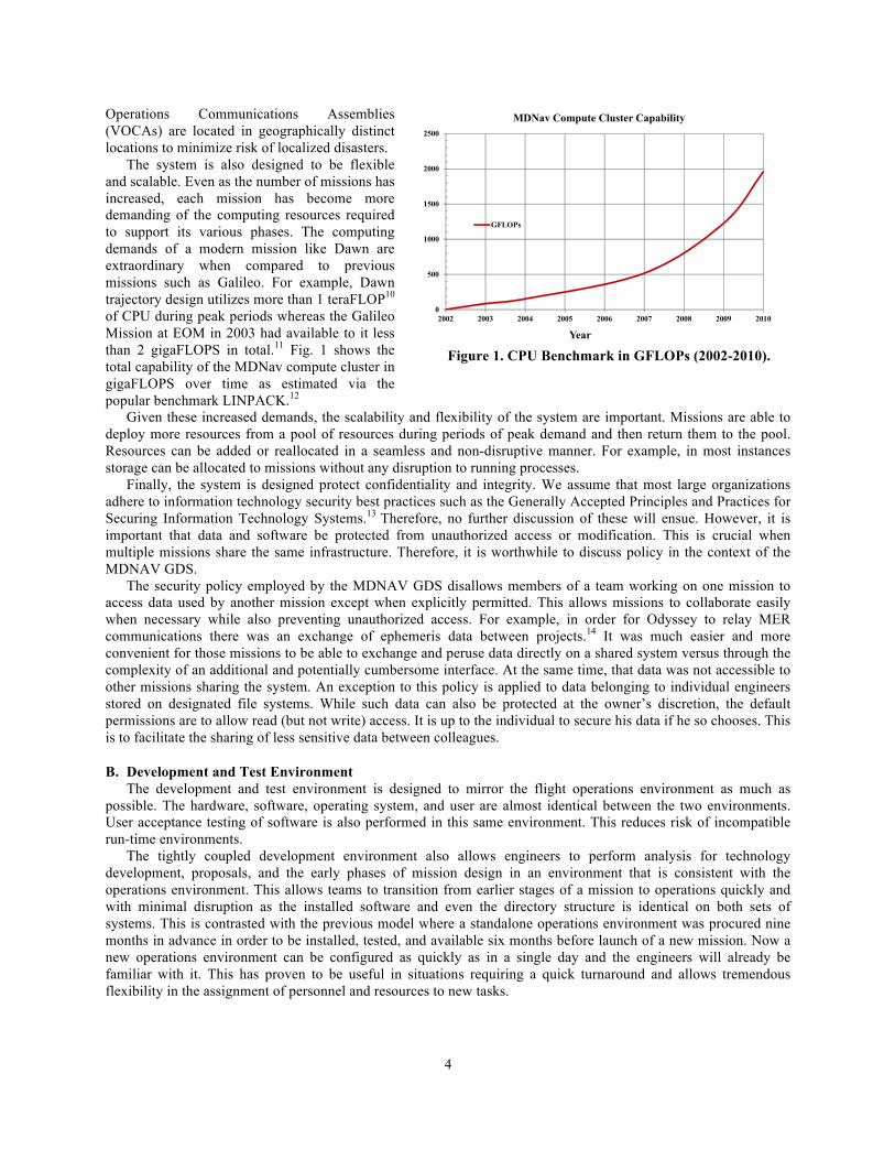
Operations Communications Assemblies (VOCAs) are located in geographically distinct locations to minimize risk of localized disasters. The system is also designed to be flexible and scalable. Even as the number of missions has increased, each mission has become more demanding of the computing resources required to support its various phases. The computing demands of a modern mission like Dawn are extraordinary when compared to previous missions such as Galileo. For example, Dawn trajectory design utilizes more than 1 teraFLOP10 of CPU during peak periods whereas the Galileo Mission at EOM in 2003 had available to it less than 2 gigaFLOPS in total.11 Fig. 1 shows the total capability of the MDNav compute cluster in gigaFLOPS over time as estimated via the popular benchmark LINPACK.12 Given these increased demands, the scalability and flexibility of the system are important. Missions are able to deploy more resources from a pool of resources during periods of peak demand and then return them to the pool. Resources can be added or reallocated in a seamless and non-disruptive manner. For example, in most instances storage can be allocated to missions without any disruption to running processes.
Finally, the system is designed protect confidentiality and integrity. We assume that most large organizations adhere to information technology security best practices such as the Generally Accepted Principles and Practices for Securing Information Technology Systems.13 Therefore, no further discussion of these will ensue. However, it is important that data and software be protected from unauthorized access or modification. This is crucial when multiple missions share the same infrastructure. Therefore, it is worthwhile to discuss policy in the context of the MDNAV GDS.
The security policy employed by the MDNAV GDS disallows members of a team working on one mission to access data used by another mission except when explicitly permitted. This allows missions to collaborate easily when necessary while also preventing unauthorized access. For example, in order for Odyssey to relay MER communications there was an exchange of ephemeris data between projects.14 It was much easier and more convenient for those missions to be able to exchange and peruse data directly on a shared system versus through the complexity of an additional and potentially cumbersome interface. At the same time, that data was not accessible to other missions sharing the system. An exception to this policy is applied to data belonging to individual engineers stored on designated file systems. While such data can also be protected at the owner’s discretion, the default permissions are to allow read (but not write) access. It is up to the individual to secure his data if he so chooses. This is to facilitate the sharing of less sensitive data between colleagues.
B. Development and Test Environment The development and test environment is designed to mirror the flight operations environment as much as
possible. The hardware, software, operating system, and user are almost identical between the two environments. User acceptance testing of software is also performed in this same environment. This reduces risk of incompatible run-time environments.
The tightly coupled development environment also allows engineers to perform analysis for technology development, proposals, and the early phases of mission design in an environment that is consistent with the operations environment. This allows teams to transition from earlier stages of a mission to operations quickly and with minimal disruption as the installed software and even the directory structure is identical on both sets of systems. This is contrasted with the previous model where a standalone operations environment was procured nine months in advance in order to be installed, tested, and available six months before launch of a new mission. Now a new operations environment can be configured as quickly as in a single day and the engineers will already be familiar with it. This has proven to be useful in situations requiring a quick turnaround and allows tremendous flexibility in the assignment of personnel and resources to new tasks.
0
500
1000
1500
2000
2500
2002 2003 2004 2005 2006 2007 2008 2009 2010
Year
MDNav Compute Cluster Capability
GFLOPs
Figure 1. CPU Benchmark in GFLOPs (2002-2010).

5
III. Ground System Architecture
A. Design The navigation ground data system development and operations environments utilize a distributed client-server
model in a star topology as shown in Fig. 2 and Fig. 3. Clustered network-attached storage devices serve data over
high-speed networks to compute-intensive applications running on compute clusters, servers, or local desktops. The MDNAV infrastructure is designed to be standalone as much as possible so as to be insulated from anomalies affecting other subsystems of a mission.
Clients are desktops primarily used for computational capabilities and are intended to be interchangeable. Compute clusters and servers are used for both interactive processes and embarrassingly parallel applications. Data is replicated across buildings and off-site to mitigate localized disasters. Data is also regularly archived when it is no longer required.
B. Configuration Management Coordination of system and software changes becomes more of a challenge in a multimission environment.
Missions have configuration freezes at differing (mission-specific) time periods and often utilize different software and hardware configurations.
We address hardware configuration changes and upgrades by coordinating these changes across all missions. This can prove difficult to schedule, but we mitigate the challenge by employing a long hardware lifecycle for critical shared resources. Therefore, such shared resources are typically upgraded at infrequent intervals. Despite the challenges imposed, this is superior to dedicating resources to each mission, because pooling of resources increases capabilities and lowers costs.
Software changes, however, are typically much more frequent. Our solution to this problem is to make all delivered versions of software accessible to all missions. Delivered software versions are software versions that have undergone formal project acceptance. We do this so that only the software we have the most confidence in is accessible to engineers in the operations environment. This is in contrast to the universe of all software versions, which may include beta or even alpha software made available in the development environment for user acceptance testing.
A common environment is maintained for each mission using a set of standardized configuration files. When engineers wish to work on a different mission they run a script that sources the correct files. These files not only setup the environment correctly, but also remove vestiges of the previous environment as well to ensure a clean working environment. This allows engineers to switch between tasks without worrying about which version of the
Clients
JPL Net
Storage
MDNavInternal Network
Archiving System
Tape Backup System
Tape Backup System
Web Servers
Compute Clusters
Compute Clusters
Backup
DSN: Goldstone, Canberra, Madrid
Industry Partners
Storage
Servers
Disaster Recovery System
Interface to DSN and Spacecraft Team
Operations Network
Figure 2. Development Architecture. Figure 3. Operations Architecture.

6
software their particular mission is required to use. It also facilitates easy access to the standardized directory structure, inputs, and data for the mission they wish to work on at the moment.
C. Hardware Hardware is provided either as part of the multimission ground data system infrastructure or by JPL’S Office of
the Chief Information Officer (OCIO). The OCIO provides e-mail, calendaring, institutional computer security infrastructure (e.g., firewalls and intrusion detection systems), institutional networks, some widely used engineering applications (e.g., MATLAB), mobile telephones, and Mac or PC laptops.
In addition to the OCIO-provided laptop, the MDNAV GDS provides desktops to each individual working in the operations environment. These are directly connected to the Operations Network. Engineers perform the majority of their analyses on these systems. Since the navigation software is computationally resource intensive, most engineers benefit from having a dedicated CPU. The higher computational requirements imposed by the type of work performed and the software utilized mean that these tend to be higher-end workstations with faster CPUs, faster I/O subsystems, and more RAM than might be expected of a typical thin client. Each desktop is intended for use by only a single engineer at a time. Borrowing cycles requires informal agreement from the primary user.
Further, there is also a requirement that engineers be able to conduct their work local to the Operations Network in the event that they cannot connect to the servers from their mobile devices. The desktops provide a more reliable and robust connection to the MDNAV GDS architecture than mobile devices and can even be used standalone (without any network connectivity) in some instances. Hardware is replenished on an approximately 5-year cycle with a roughly equal portion replaced each year. This is to help keep costs down and yet not allow hardware to fall too far behind the latest technology. It also allows the system to be more reliable and robust, as older hardware components are more likely to fail.15 Managing the procurement cycle in this manner helps enable the multimission environment by allowing a mix of older and newer hardware. Newer hardware can be deployed when and where it is most needed. It is conceivable that the 5-year cycle might have to be revisited if the pace of hardware technology development changes rapidly. 4-year or even 3-year cycles might have made more sense at various times in the past and might again in the future. It is not recommended to have longer cycles as hardware failure rates increase markedly beyond the 5-year mark.16
1. Desktop hardware
Desktops are typically Intel-based hardware running Red Hat Enterprise Linux. Desktops are specified to have enough computing power to be able to perform all but the most intensive navigation-related tasks. It is assumed that engineers will perform most of their analysis using these systems. Since most mission design and navigation software is resource-intensive, these systems are more capable than a typical thin client in order to support that.
Hardware is replaced independent of any mission milestones on a 5-year replenishment cycle with a strong desire to replace approximately 20% each year. Making procurements each year allows us to have some flexibility in our forecasting. Mission extensions, mission failures, workforce fluctuations, and other unforeseen events may prompt us to make adjustments to planned procurements. This is a benefit compared to the previous model where all hardware was purchased at once at the start of a mission or on fixed intervals according to a relatively inflexible schedule determined far in advance.
This flexibility can be very powerful, as sometimes advances in technology do not align well with budgetary planning. The previous model sometimes resulted in hardware procured up front according to plan with substantially better technology on the horizon and no ability to upgrade to it for some time. With the multimission approach, missions can more easily allocate the resources where they are needed in a given time period with the potential to upgrade to better hardware in a year or less. That newer, faster hardware can be more quickly infused into the MDNAV GDS to be deployed where it can be best utilized. Missions do not have to wait for up to 5 years to take advantage of new technology that may benefit them.
This benefit has already been realized by the Dawn mission, which utilizes software whose performance is heavily dependent on the size of L2 and L3 cache. Dawn was 4 years past launch into its approximately 8-year mission17 when cache sizes on processors increased markedly. We were able to infuse hardware with larger cache sizes into the MDNAV GDS to benefit Dawn and by replenishing 20% of the hardware each year we have the option to continue to do so later in the mission should cache sizes continue to increase. Missions are not penalized as heavily for incorrect forecasts made years in advance nor locked into hardware options available at a given point in time.

7
2. Server hardware Servers exist primarily as compute servers accessed over the network. These are typically rack-mounted, Intel-
based hardware running Red Hat Enterprise Linux. They provide more capable hardware than exists on the desktops with multiple and faster CPUs, larger amounts of RAM, and faster network interfaces than would be cost-effective on the desktops. They are intended to be a shared resource used by engineers on flight teams with their own desktops when they need more computing power, but also by engineers who may not have their own desktops, perhaps because they are transitory collaborators.
The servers are intended to be more permanent than the desktops. They provide an environment in which automated processes can more safely run long-term. Desktops are often moved between buildings, individuals, or even missions in order to meet mission requirements and fluctuating staffing levels, but the servers are expected to provide a stable computing platform with minimal downtime. Servers have a faster, more reliable connection to the Operations Network and to storage making them both faster and more robust than the desktops.
The number of servers is relatively constant, but is tied to observed usage along with requirements gathered in advance from missions expected to utilize large amounts of CPU. There is more of an effort to replace the servers all at once instead of at the rate of 20% per year as with the desktops. Reasons for this include limiting downtime and scheduling concerns. This rationale is explained further under Lessons Learned. Another reason is because engineers have a tendency to flock to the fastest hardware, which has a tendency to slow it down. By replacing it all at once there is no “preferred” hardware. 3. Storage Most storage is network-attached. Local storage is provided in limited quantities and should be used only as scratch space. This local storage is not accessible from other devices. It exists because in certain circumstances engineers require the creation of large temporary files as part of their process. There are also sometimes performance considerations such as when an application needs to perform a large amount of I/O.
The network-attached storage is available to all clients over high-speed networks. It is clustered for reliability and performance. Failure of any one storage device will not significantly impact mission operations. Storage is allocated dynamically between missions. In most cases, storage can be added or subtracted without any downtime.
4. Network The network interfaces across the JPL campus, between JPL and the Deep Space Network (DSN), between JPL and other external partners, and between JPL and the Internet are managed by OCIO. MDNAV maintains its own separate high-speed networks for internal communications between certain resources managed by MDNAV. These are required for functions such as high performance computing and network-based backups. Technologies employed are InfiniBand and both 1 Gigabit and 10 Gigabit Ethernet.
D. Software The chosen operating system is Red Hat Enterprise Linux. This evolved naturally from a combination of factors,
but the driving factor was that most software was ported to a UNIX operating system in the early 1990’s for hardware performance reasons and thus retained a strong UNIX heritage. When the MDNAV GDS was designed the trend that drove the choice to Linux and away from other UNIX operating systems was primarily the speed and value of Intel-based hardware compared to available HP PA-RISC and Sun SPARC systems available at the time.18
Red Hat was chosen as the vendor because it was considered important to obtain enterprise-level support for the operating system over a long product lifecycle.19
The navigation software is written to be multimission in nature, which helps enable a multimission environment. This means the capabilities required for all missions are present in each release. There is no need to package software releases specific to each mission. As a result, there are more users testing each release and bugs are likely to be found more quickly. The fact that the software development environment is tightly coupled with the MDNAV GDS environment enables all missions to easily accept new software releases if they so choose. This allows new software to be quickly made available for testing by the user community without the requirement to install on a separate test bed. This shortens development and test cycle times. It also allows new software releases to be utilized in operations more swiftly.
E. Backup and Archive In the operations environment, backups are limited to network-attached storage. Clients and servers are not backed up in any way in the operations environment. This is because the operations environment has more stringent availability requirements. Restoring local data would increase the mean-time-to-restore of systems. Local storage is
8
presumed to be scratch space containing only intermediate products. Incremental backups of the network-attached storage are performed daily while full backups are performed quarterly and sent offsite for one year. Annual backups are performed each year and sent offsite indefinitely. In the development environment, in addition to the same policies as above for network-attached storage, full backups are performed weekly of any data residing locally on the clients. This difference is policy is primarily because in the development environment performance is valued over availability. Local storage is often faster than network-attached storage. Quarterly and annual backups are also sent offsite according to the same policy. Archiving is performed at the request of the users during active mission phases or else by default at EOM as part of deprovisioning. Each mission has an archive area to which it may copy data that it wishes to archive. The data is copied to an archive server where it is left online indefinitely for any MDNAV user to access. This data has already proven useful as a reference for later tasks such as proposals. A copy of the data is also written to optical media and stored offsite indefinitely.
F. Facilities A natural consequence of flying more missions simultaneously is that there are likely to be more critical events
necessitating use of a Mission Support Area (MSA). It quickly became apparent that a single MSA would not be sufficient to meet predicted demand from missions. Further, the unavailability of a single MSA in the event of a localized disaster could result in loss of a mission. Therefore, it was decided that the MDNAV GDS needed to have multiple MSAs with duplicate capabilities. At this point in time there are multiple MSAs on-site and a mini-MSA off-site. These MSAs are outfitted with client workstations, VOCAs, projectors, printers, fax machines, and direct connectivity to the Operations Network. They also have generator-backed power. These are in addition to any project-provided MSAs and are dedicated to critical navigation support and meetings.
Shared compute resources are in a separate, dedicated data center also with generator power. This allows for easier consolidation of multimission resources, reduces costs related to networking, and allows for controls on the environment and physical security.
IV. Becoming a Service Center It became clear that a MDNAV GDS infrastructure would be cumbersome to maintain given existing constraints imposed by the accounting rules for procurements. For example, there are very strict rules regarding the pooling of funds from accounts with differing end dates. This was especially inconvenient when negotiating service contracts and extended warranty support. The fiscal year boundary posed an additional constraint that made procurements and maintenance agreements difficult to arrange. In addition, the uneven and inconsistent nature of funding made available according to individual project schedules complicated planning.
It was decided that a better strategy was to run infrastructure as a service. To that end, a Service Center was setup as a mechanism for pooling funds, procuring contracts, and assisting with long-term planning. It also allowed missions to dedicate just a single, predictable line item in their budget for maintaining the MDNAV GDS. It has been run this way since 2007.
The primary objective of the service center is to: provide infrastructure necessary to enable mission design and navigation capabilities for JPL projects/tasks and researchers; provide system engineering and systems administration support related to that infrastructure; accurately tabulate the costs associated with these functions; and distribute those costs in an equitable manner to the end users. There were many immediate benefits to becoming a Service Center. While establishing a Service Center was not strictly necessary in order to employ a multimission approach to navigation ground data system operations – and indeed this approach was adopted prior to the establishment of the Service Center - it has made the transition more successful in the following ways:
• The Service Center provides ease of administration. The team managing the MDNAV GDS previously spent a lot of time negotiating budgets, comparing financial schedules, and defending the same procurement and staffing decisions to each project individually. These same duties must still be performed to an extent, but the Service Center allows the management team to view the MDNAV GDS as a single cost account with its own schedule and budget. This makes administration easier. An example of this is that previously projects would often maintain their own individual charge accounts rather than provide an account for the MDNAV GDS administrative team to manage. Visibility into the financials of these accounts was often limited. It was sometimes impossible to know the specifics of a particular

9
account without the help of up to 40 different Project Resource Administrators (PRAs). The Service Center makes that information much easier to gather and distribute. The ability to easily view costs across the entire MDNAV GDS makes the administration of it more efficient. It is no longer necessary to contact the PRAs to obtain basic information for each cost account such as start and end dates. Such communication is now only necessary to address specific questions and concerns. Reporting is made simpler with a unified reporting structure that serves as a reference for projects seeking answers to common questions and information is disseminated to all projects at once.
• The Service Center allows pooling of financial resources.
If any single mission is cancelled, fails, changes drastically in scope, or is otherwise unable to contribute funds to the infrastructure it is not a fatal blow to the ability to maintain the infrastructure. Previously, there was a heavier reliance on missions with big budgets to contribute funding because of the relative difficulty of pooling finances from myriad small missions. If a large procurement needed to be made that required pooling of many resources then the failure of even one project to adhere to the agreed schedule and budget (sometimes due to circumstances outside of their direct control) could derail the entire procurement and jeopardize the ability of other missions to meet their requirements. Pooling resources mitigates this risk and allows flexibility to address changes in requirements or scope. Also worth noting is that legacy missions (those whose accounting structure was established prior to the multimission architecture) were often unable to change their work breakdown structure (WBS) to accommodate the new multimission paradigm even if they wished to participate. With the Service Center, such missions are able to contribute funding despite any existing WBS limitations. • The Service Center provides increased flexibility and reduces risk.
The Service Center has enabled missions to have access to a broader range of more capable resources than they would have been able to provide for themselves. This is especially true for small, low-cost missions, who now have access to the resources of the broader pool of missions. This has increased reliability and reduced risk for such missions, as they have access to an infrastructure they would not be able to afford otherwise. This is especially valuable if requirements change drastically during mission operations. Likewise, it has also provided resources such that when missions are extended beyond EOM they still have access to the broader pool of resources that are continually updated and maintained. Further, it has allowed projects with very short cycle times to utilize the resources of the entire MDNAV GDS while contributing funding only during the duration of their use.
• The Service Center allows management to focus on high-level strategy.
Previously, considerable time was spent gathering requirements from each mission, inquiring about available budgets, determining each mission’s procurement schedule, trying to build consensus among missions, and attempting to spread out costs in an equitable fashion. This required considerable time of both the MDNAV GDS management team and the Cost Account Managers (CAMs). Now, regular meetings with CAMs allow them to ask questions, voice concerns, make requests, and provide feedback. These meetings also provide a forum for the representatives of different projects to share information, relate experiences, and solve problems related to the design, operations, and maintenance of the infrastructure. The Service Center also makes budget exercises for CAMs much more streamlined. With the advent of the Service Center, CAMs can include a single line item in their budgets for infrastructure and support without worrying as much about details such as the level of support required or the specifications of the particular hardware and software needed to meet requirements common to all missions. This permits them to concentrate more heavily on mission-specific requirements and other higher-level issues such as the determination of appropriate staffing levels and schedules.
• The Service Center assists with the procurement of maintenance contracts.
The Service Center allows the procurement of hardware and software maintenance contracts on an annual basis even if the underlying accounts terminate during the course of a fiscal year. This is possible because the Service Center account does not terminate at the fiscal year boundary. Previously, it was sometimes impossible to procure maintenance contracts given the large numbers of charge accounts each with varying end dates.
10
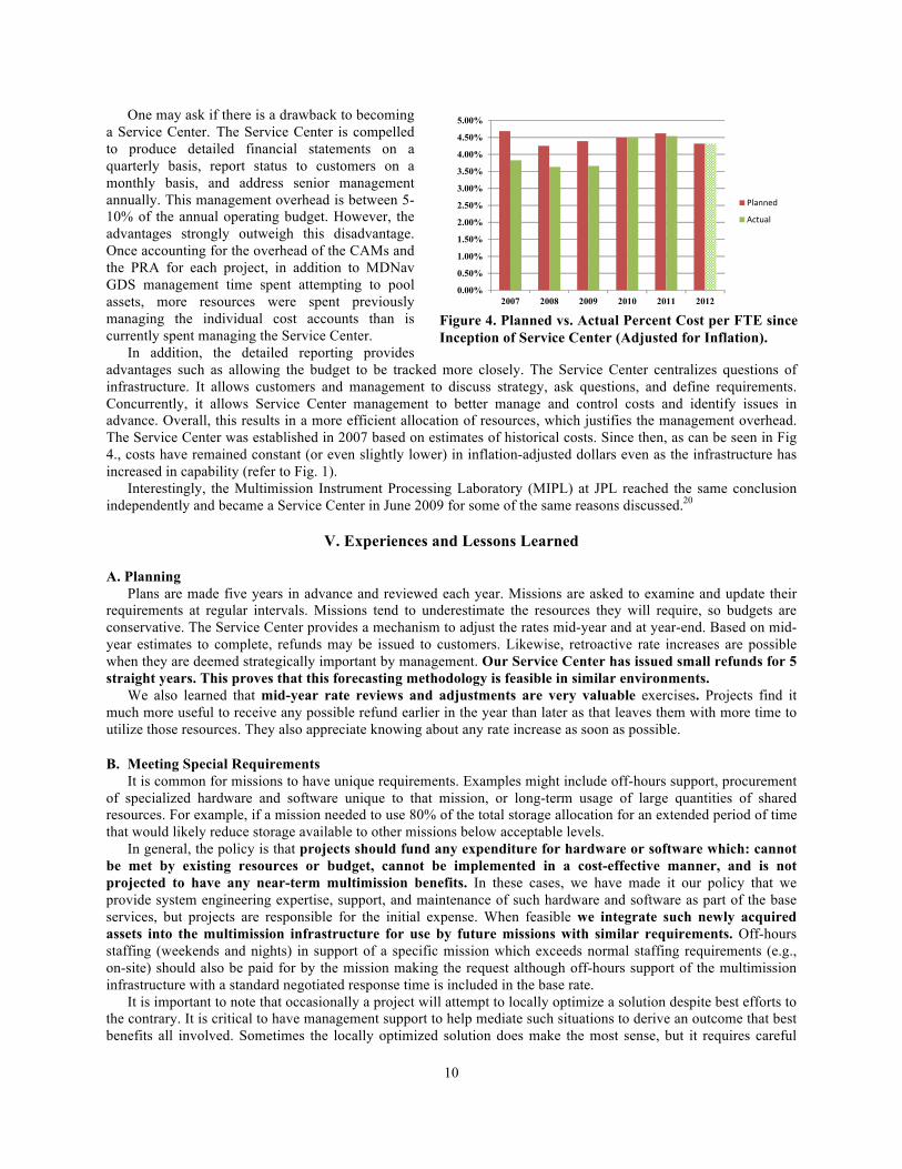
One may ask if there is a drawback to becoming a Service Center. The Service Center is compelled to produce detailed financial statements on a quarterly basis, report status to customers on a monthly basis, and address senior management annually. This management overhead is between 5-10% of the annual operating budget. However, the advantages strongly outweigh this disadvantage. Once accounting for the overhead of the CAMs and the PRA for each project, in addition to MDNav GDS management time spent attempting to pool assets, more resources were spent previously managing the individual cost accounts than is currently spent managing the Service Center. In addition, the detailed reporting provides advantages such as allowing the budget to be tracked more closely. The Service Center centralizes questions of infrastructure. It allows customers and management to discuss strategy, ask questions, and define requirements. Concurrently, it allows Service Center management to better manage and control costs and identify issues in advance. Overall, this results in a more efficient allocation of resources, which justifies the management overhead. The Service Center was established in 2007 based on estimates of historical costs. Since then, as can be seen in Fig 4., costs have remained constant (or even slightly lower) in inflation-adjusted dollars even as the infrastructure has increased in capability (refer to Fig. 1). Interestingly, the Multimission Instrument Processing Laboratory (MIPL) at JPL reached the same conclusion independently and became a Service Center in June 2009 for some of the same reasons discussed.20
V. Experiences and Lessons Learned
A. Planning Plans are made five years in advance and reviewed each year. Missions are asked to examine and update their
requirements at regular intervals. Missions tend to underestimate the resources they will require, so budgets are conservative. The Service Center provides a mechanism to adjust the rates mid-year and at year-end. Based on mid-year estimates to complete, refunds may be issued to customers. Likewise, retroactive rate increases are possible when they are deemed strategically important by management. Our Service Center has issued small refunds for 5 straight years. This proves that this forecasting methodology is feasible in similar environments.
We also learned that mid-year rate reviews and adjustments are very valuable exercises. Projects find it much more useful to receive any possible refund earlier in the year than later as that leaves them with more time to utilize those resources. They also appreciate knowing about any rate increase as soon as possible.
B. Meeting Special Requirements It is common for missions to have unique requirements. Examples might include off-hours support, procurement
of specialized hardware and software unique to that mission, or long-term usage of large quantities of shared resources. For example, if a mission needed to use 80% of the total storage allocation for an extended period of time that would likely reduce storage available to other missions below acceptable levels.
In general, the policy is that projects should fund any expenditure for hardware or software which: cannot be met by existing resources or budget, cannot be implemented in a cost-effective manner, and is not projected to have any near-term multimission benefits. In these cases, we have made it our policy that we provide system engineering expertise, support, and maintenance of such hardware and software as part of the base services, but projects are responsible for the initial expense. When feasible we integrate such newly acquired assets into the multimission infrastructure for use by future missions with similar requirements. Off-hours staffing (weekends and nights) in support of a specific mission which exceeds normal staffing requirements (e.g., on-site) should also be paid for by the mission making the request although off-hours support of the multimission infrastructure with a standard negotiated response time is included in the base rate.
It is important to note that occasionally a project will attempt to locally optimize a solution despite best efforts to the contrary. It is critical to have management support to help mediate such situations to derive an outcome that best benefits all involved. Sometimes the locally optimized solution does make the most sense, but it requires careful
0.00%
0.50%
1.00%
1.50%
2.00%
2.50%
3.00%
3.50%
4.00%
4.50%
5.00%
2007 2008 2009 2010 2011 2012
Planned
Actual
Figure 4. Planned vs. Actual Percent Cost per FTE since Inception of Service Center (Adjusted for Inflation).

11
consideration by all involved parties. It is important to foster an atmosphere of cooperation and avoid dictating solutions to projects or having projects dictate solutions.
C. Cultivate Relationships It is important to maintain relationships with other entities both at JPL and with outside organizations. For
example, our relationship with JPL’s supercomputing group has helped us obtain resources to solve difficult problems. It is not helpful to build an isolated silo within the organization. Instead, it is important to engage both internal partners and outside organizations for advice and support.
On the other hand, it is important to represent the missions well in interactions with other organizations, even those within JPL. Sometimes the missions are so focused on the task at hand that they are unaware of developments that have potential to help or harm them. It is important to make them aware of such developments as soon as possible so that they can participate in orchestrating the desired outcome. They have more leverage than the line organization in certain matters.
Conversely, many times partnering organizations (both within and external to JPL) do not well understand what it is your organization (or the customer you represent) does. For example, it is well understood that when a trajectory correction maneuver executes that is a critical time for a mission. However, other organizations may not realize that there are periods of time critical to the execution of that maneuver which may occur days before the actual execution of the maneuver. Such periods may even be more critical and sensitive to disruption than the execution of the maneuver itself because of other constraints or requirements. Continuing the example, maneuvers are often designed and uplinked even days in advance of the actual execution. It is important to educate both internal stakeholders and external organizations about the work being done to build relationships and understanding when there is potential for conflict.
D. Handling Scheduling Conflicts In a multimission environment, it is very common that some critical activity being conducted by one of the
missions. Fig. 5 demonstrates the scheduling challenges faced in a multimission environment.
Figure 5. Mission Schedules with Mission Design and Navigation Focus (March 2011-October 2012). The author would like to thank Joseph Guinn (JPL/Caltech) for producing this Figure and allowing its publication.

12
Operating in such an environment can make it very difficult to schedule time for maintenance of shared resources such as network switches. There will seemingly always be a mission or task that cannot tolerate any outage. Experience has shown that it is better to propose a date (and an alternate date or several) than to ask missions for a good time. There is never a good time. By proposing a date and time, the missions are forced to examine the schedule and consider alternatives to their existing timeline. If it is a tough window to schedule, consider investing time to system engineer a solution for the missions unable to comply. We have often found that viable solutions exist once the actual requirements are known.
Another tactic is to try to perform several tasks in a given maintenance window. It is frustrating for missions to have to experience frequent disruptions. It seems preferable to have fewer disruptions of longer duration, presumably because it is easier to plan around a single event of longer duration than multiple events of short duration. This is the reason we decided we should make it policy to upgrade the compute servers all at once if possible.
However, care should be taken to strike a balance between too many and too few periods of scheduled maintenance. For example, if too many configuration changes occur during a window it may be difficult to isolate the source of any later disruptions. Make sure scheduled maintenance windows allow adequate time for testing and even a rollback. If a rollback is not feasible, prepare contingency plans in advance.
For large changes, discuss possible suboptimal outcomes with projects in advance. Missions assume that when the window has passed that they will be able to continue nominal operations. If there is a reasonable chance that a contingent situation might extend the window or that the work being performed could impact any other services (dependent or not) that should be communicated to missions in advance.
E. Resolving Resource Conflicts One issue with a shared multimission system is that there can be contention for resources. This can manifest
itself as contention for disk space, CPU, I/O, network bandwidth, physical facilities, personnel, or any other resource.
1. Storage
One issue with shared storage is that one mission may use up all available space and reduce the amount of space available to the other missions in the process. We learned that the easiest way to prevent contention for storage is to provide each mission its own dedicated storage. Even though a given network storage device may be shared by many missions, each mission is allocated its own volume. This prevents one mission from using up all of the available free space and impacting other missions. It also forces missions to more closely examine their usage and delete or archive more frequently.
Another issue involving storage is how to allocate available space. Clearly different missions have different requirements for storage. Rather than adopt simplistic methods such as dividing the storage up equally or allocating storage according to financial contributions, we take the approach of allocating storage according to projected need. This is determined from the surveys we issue as well as interaction with the project leads. In order to prevent a mission from intentionally overstating its requirements, storage is purchased according to stated requirements, but allocated on an “as needed” basis. Current usage is compared to projected usage and storage is added if needed. Storage can also be allocated on a temporary basis if a mission finds that its storage needs will be larger than predicted, but for a short period of time. This is negotiated with the mission making the request.
When it comes to storage for individuals, we found that it was a necessity to implement quotas on certain shared file systems. We encourage engineers to store their data in project-related areas where there are no quotas placed on individuals. That way data associated with a particular mission stays with the mission as a data set. In a multimission environment it can become easy to lose track of which data belongs to which missions. This can be a problem for analysts later searching for archived data relating to a particular mission. However, it is understandable that individuals also need some storage of their own for personal notes and other data. Therefore, each individual is allocated a token amount of storage on a shared file system and this usage is enforced with quotas. A user’s quota may be increased only if he demonstrates need. This requires an explanation of why the data cannot reasonably reside in a mission-specific area. This policy is necessary because without quotas a given user would be able to consume all available space on the shared file system. This would impact users working on other missions and so it is to be avoided.
Finally, it is good practice to purchase more storage than missions predict they will use. Increases in storage use are not always linear and estimates based on historical usage and analysis performed in the early phases of missions tends to underestimate need in our experience. We tend to budget for small additions to storage even when we predict they may not be needed. If the allocated funds are truly not needed, they can be returned to the missions
13
during the year. This is preferable to running out of storage at an inopportune moment, because it is precisely during the activities when storage is most needed that it becomes scarce.
2. CPU
CPU is the resource most frequently in contention. MDNAV software applications are CPU intensive by nature. They require lots of floating point operations and tend to be limited by clock speed. The preponderance of multi-core CPUs has ameliorated some of the contention, but at the same time increasing requirements for embarrassingly parallel processing conspire to apply pressure.
When asked how much CPU capability is required, the standard project response is “as much as we can get.” To address this unbounded requirement, we split our CPU resources up into multiple, but substantially similar, compute clusters. We have found that this is easier to manage in a multimission environment than one single cluster. By partitioning the system, we can dedicate a “whole” cluster to a particular task and yet leave other parts of the system available to interactive uses. This approach requires quite a bit of coordination and requirements gathering, but it has served us well so far.
3. Network and I/O
Allocating and managing network (and other I/O) bandwidth is one of the greatest challenges. Contention can be hard to detect and culprits can be difficult to identify in a multimission environment with many interconnected devices accessed by many users simultaneously. Since we do not manage the Wide Area Networks (WAN) we have very little influence over their design and capacity. Our strategy is to minimize their use when possible. Even on the Local Area Networks (LAN) we do manage, it is difficult to achieve high speeds and low latency without considerable expense. Our best option for handling network contention is to discover the devices that consume the most bandwidth and identify possible causes. Even with sophisticated monitoring tools this process may involve trial and error in a complex environment. Depending on the results of the investigation we may: upgrade the associated infrastructure, isolate identified devices to minimize impact on others, or assist with engineering alternative lower bandwidth strategies to accomplish the task in question. 4. Facilities
Facilities conflicts are unavoidable. It is inevitable that on occasion different missions will vie to use the MSAs at the same time for critical activities. The best solution is to have facilities first-come, first-served and have management moderate conflicts with the caveat that each mission is assigned a preferred MSA for designated critical events. This rewards careful planning, but allows strategic decisions to be made. In the event of a critical event conflicting with another mission’s activities, the “preferred” mission is typically given priority to resources and the conflicting mission must utilize a different MSA. Duplicating capabilities in each MSA is important for this to work and it necessarily means that there needs to be at least one MSA for each projected simultaneous critical event. An increase in conflicts may point to the need for additional facilities.
5. Staffing Occasionally, there is contention for personnel. Either there is not enough staff available to meet demand because of circumstances outside of one’s control (e.g., sick leave) or sometimes missions become very demanding of a particular individual’s time for various reasons including personality, previous history, perceived competence levels, or other reasons. We have made it a policy to cross-train every member of the support staff as much as possible so that they are competent and familiar with the requirements of each mission. The goal is that any member of the team can support any mission. In reality different individuals do have different competencies and other factors may come into play. For example, if one team has a reputation as a go-to individual he may not be able to service all of the missions to the extent that they would prefer. Since the systems engineering and systems administration staff does not directly work for the missions, the final say in staffing decisions is with the line organization. This can sometimes make projects uncomfortable, as they like to feel a sense of ownership. To offset this discomfort we assign different team members as leads or liaisons between particular missions and the line organization. That way, the missions get used to interfacing with the same personnel and having the same points of contact in a general sense. The assigned leads also develop a deeper familiarity with the mission, its project personnel and its specific (and possibly unique) requirements. That is not to say that the lead is dedicated to the mission or that other team members will not step in to solve problems as available. Rather, each mission has a subject matter expert who has a deeper familiarity with the mission and its particular concerns. It is the

14
responsibility of that person to act as a liaison between the mission and the rest of the staff and vice-versa. For example, this might occur when trying to schedule downtime such that there is a consistent point-of-contact.
VI. Challenges Ahead
A. Cloud Computing JPL has made a significant investment in cloud computing. There are obvious advantages to using the cloud in
some instances. For example, when one has need of a large number of CPUs for a short duration it can be cost effective to employ the cloud. This use seems particularly compelling in cases where modeling or Monte Carlo-type studies need to be performed as part of mission design or in similar cases where a disruption will not impact mission operations directly.
The cloud may also hold some advantages in terms of accessibility from remote sites. This could be useful for data exchange or collaboration with external partners. In the case of certain localized disasters the cloud may be more available as it is geographically dispersed. The idea of moving data to the cloud as part of a disaster recovery plan seemingly has some merit.
The challenges with cloud computing are primarily in security, privacy, and legal issues. It is unclear what value service levels agreements (SLAs) have to an organization like JPL. It is unclear who owns the data stored on the cloud and what rights the cloud vendor has to the data. Security on the cloud is difficult to assess, as cloud vendors are notoriously vague when it comes to revealing the details of their infrastructure.
There are also concerns about the fundamental necessity of network connectivity in order to utilize the cloud. There are certain interfaces like the Deep Space Network (DSN) that must be accessible in order to receive tracking data, point antennas, and command and control spacecraft. It is not clear that the network infrastructure is yet aligned in such a way as to make the transfer of data between the cloud and such interfaces feasible in a robust and secure manner. In general, transferring data to and from the cloud may prove to be a larger challenge than proponents claim.
Nevertheless, we do expect to utilize the cloud more in coming years and attempt to integrate it into the existing infrastructure where it makes sense to do so. We expect that initially we may attempt to utilize the cloud in order to augment, not replace, local resources in most instances.
Some questions we will attempt to ascertain the answers to over the coming years: 1) Should data moved to the cloud be encrypted? What impacts will that have on performance? 2) How oversubscribed is the infrastructure and will it be there when it is needed? 3) What components of infrastructure are critical to keep in the local data center and which can be outsourced to
the cloud? 4) How will costs to perform mission design and navigation utilizing the cloud compare to current costs? 5) What will happen to costs over time?
B. Mobile Computing Along with the cloud, mobile computing is an emerging trend. The traditional desktop PC is not only being
replaced by laptops for many uses, but remote access solutions on mobile devices are proliferating. The challenges of mobile computing are: 1) Configuration management of mobile devices. 2) Porting existing applications to run on mobile devices. This could prove to be very expensive. 3) Transferring content over still relatively slow wireless networks. 802.11ac21 and 802.11ad22 may change this,
but how will these standards perform with the I/O saturated applications used in navigation operations? 4) Security and reliability of mobile devices and networks.
VII. Conclusion We sought to optimize infrastructure across the MDNAV organization by designing a single multimission
navigation ground data system to support all projects. This required a lot of management support as projects were heavily invested in the old paradigm. Project managers were understandably more often concerned about their own bottom line than about overall cost.
However, the new paradigm has proven itself worthy to project management. It has allowed the increased numbers of smaller missions with faster development cycles to thrive. Standing up a MDNAV GDS for a small mission or quickly needed analysis can now be done in a single day with no delays for procurements or other overhead. The existing infrastructure has enough flexibility built in to accommodate all but the largest missions and
15
most demanding tasks quickly and efficiently. Even larger missions have benefitted by the flexibility afforded to them and the ability to pool costs for shared resources.
The overall GDS capabilities available to each mission have increased at the same time that costs per mission have been reduced as a result of standardization, inheritance, and the reuse of resources, which the multimission approach enables. We have proven that it is possible to construct a multimission mission design and navigation GDS with a stable and predictable cost structure (refer to Fig. 4) that is able to simultaneously support at least seven active missions (refer to Table 1 and Fig. 5) with several more in development. We have also demonstrated that with this model it is possible to increase procurements to meet new mission requirements with the same overhead while strengthening the shared infrastructure. In fact, Fig. 4 shows our overall rate has not increased even as over the same period our infrastructure experienced significant growth in order to accommodate an unprecedented number of missions in operations.
16
Appendix A Acronym List
ARC CAM CPU DSM DSN EDL EOM ESA FTE
Ames Research Center Cost Account Manager Central Processing Unit Deep Space Maneuver Deep Space Network Entry, Descent, and Landing End of Mission European Space Agency Full Time Equivalent Employee
GDS GSFC I/O ISRO JAXA
Ground Data System Goddard Space Flight Center Input/Output Indian Space Research Organization Japanese Aerospace Exploration Agency
JPL L2 L3 LAN LINPACK LOI MDNAV MER MIPL MRO MSA
Jet Propulsion Laboratory Level 2 Cache Level 3 Cache Local Area Network Linear Equations Software Package Lunar Orbit Insertion Mission Design and Navigation Mars Exploration Rovers Multimission Instrument Processing Laboratory Mars Reconnaissance Orbiter Mission Support Area
NASA OCIO
National Aeronautics and Space Administration Office of the Chief Information Officer
PA-RISC PRA
Precision Architecture-Reduced Instruction Set Project Resource Administrator
RAM Random Access Memory SLA Service Level Agreement SPARC TCM WAN
Scalable Processor Architecture Trajectory Correction Maneuver Wide Area Network
WBS Work Breakdown Structure
Acknowledgments The authors extend thanks to William Taber, Robert Beswick, and Tim McElrath for making this paper possible
with their editing, commentary, and support. Special thanks to Joseph Guinn for compiling and providing the mission schedules. We would also like to thank Tomas Martin-Mur, Belinda Arroyo, Stacy Weinstein-Weiss, Dongsuk Han, L. Alberto Cangahuala, Shyam Bhaskaran, Elsa Waters, Jasmeen Daof, Katherine Nakazono, Gregory Dube, Michael Watkins, Louis D’Amario, and William Owen for their contributions to the ideas presented in this paper and assistance in the implementation of the described system.
This research was carried out at the Jet Propulsion Laboratory, California Institute of Technology, under a contract with the National Aeronautics and Space Administration. Reference to any specific commercial product, process, or service by trade name, trademark, manufacturer or otherwise, does not constitute or imply its endorsement by the United States Government or the Jet Propulsion Laboratory, California Institute of Technology.
17
References 1McCurdy, H. E., Faster, Better, Cheaper: Low-Cost Innovation in the U.S. Space Program, The Johns Hopkins University
Press, Baltimore, MD, 2001, pp. 1-10. 2Bearden, D. A., “A complexity-based risk assessment of low-cost planetary missions: when is a mission too fast and too
cheap?” Acta Astronautica, Vol. 52, No. 2, Jan. 2003, pp. 371-379. 3Spear, A. J., “NASA Faster, Better, Cheaper Final Task Report,” March 13, 2000, URL:
http://mars.jpl.nasa.gov/msp98/misc/fbctask.pdf [cited 26 April 2012]. 4Butrica, A. J., “Deep Space Navigation, Planetary Science, and Astronomy: A Synergetic Relationship,” NASA 50th
Anniversary Proceedings. NASA's First 50 Years: Historical Perspectives edited by Dick, S. J., NASA, Washington, D.C, 2010, pp. 495.
5Beswick, R. M., Antreasian, P. G., Gillam, S. D., Yahn, Y., Roth, D. C., and Jones, J. B., “Navigation Ground Data System Engineering for the Cassini/Huygens Mission,” AIAA Paper 2008-3247, SpaceOps 2008 Conference, Heidelberg, Germany, May 12-16 2008, pp. 4-5, 7.
6Zurek, R. W., and Smrekar, S. E., “An overview of the Mars Reconnaissance Orbiter (MRO) science mission,” Journal of Geophysical Research, Vol. 112, E05S01, 2007, p. 11.
7Johnston, M. D., Herman, D. E., Zurek, R. W., and Edwards, C. D., “Mars Reconnaissance Orbiter: Extended Dual-Purpose Mission,” Proceedings of the 2011 IEEE Aerospace Conference, IEEE Aerospace and Electronic Systems Society, Piscataway, NJ, 2011, pp. 4, 14.
8Chow, D., “NASA Rover Arrives at Huge Mars Crater After 3-Year Trek,” URL: http://www.space.com/12594-nasa-mars-rover-opportunity-arrives-huge-crater.html [cited 26 April 2012].
9Christensen, E. J., “Advances in Multimission Navigation Systems at NASA/JPL,” Proceedings of the 31st Scientific Assembly of Cospar, COSPAR, Birmingham, U.K., July 1996 [abstract], URL: http://hdl.handle.net/2014/25468 [cited 26 April 2012].
10Gepner, P., Fraser, D.L., and Kowalik, M.F., “Evaluating Performance of New Quad-Core Intel® Xeon® 5500 Family Processors for HPC,” Lecture Notes in Computer Science, No. 6067, Springer-Verlag, Berlin, 2010, pp. 5-6.
11Guest, M. F., “Performance of Various Computers in Computational Chemistry,” Proceedings of the 15th Daresbury Machine Evaluation Workshop, CLRC Daresbury Laboratory, Warrington, United Kingdom, February 2005, URL: http://www.cfs.dl.ac.uk/benchmarks/compchem.html [cited 26 April 2012].
12Dongarra, J. J., “Performance of Various Computers Using Standard Linear Equations Software,” University of Tennessee Computer Science Technical Report, CS-89-85, 2011, pp. 2-52.
13Swanson, M., and Guttman, B., “Generally Accepted Principles and Practices for Securing Information Technology Systems,” National Institute of Standards and Technology Special Publication 800-14, United States Department of Commerce, Washington, D. C., 1996.
14Esposito, P. B., Bhat, R., Demcak, S., Ardalan, S., Breeden, J., Helfrich, C., Jefferson, D., and Stauch, J., ”Mars Global Surveyor and Mars Odyssey - Relay Satellites for the Mars Exploration Rover Mission,” AIAA Paper 2004-5094, AIAA/AAS Astrodynamics Specialist Conference and Exhibit, Providence, RI, August 16-19 2004, pp. 1-2, 10-13.
15Schroeder, B., Pinheiro, E., and Weber, W-D., “DRAM Errors in the Wild: A Large-Scale Field Study”, Communications of the ACM, Vol. 54, No. 2, Feb. 2011, pp. 103-104
16Schroeder, B., and Gibson, G., “Understanding Failures in Petascale Computers,” Journal of Physics: Conference Series, Vol. 78, 2007, pp. 4-6.
17Rayman, M. D., Fraschetti, T. C., Raymond, C. A., and Russell, C. T., “Dawn: A mission in development for exploration of main belt asteroids Vesta and Ceres,” Acta Astronautica, Vol. 58, No. 11, Apr. 2006, pp. 605-616.
18Beswick, pp. 8-9. 19Red Hat Enterprise Life Cycle, URL: https://access.redhat.com/support/policy/updates/errata/ [cited 26 April 2012]. 20Henricks, J. A., Hall, L., and Fung, J. G., “Supporting Operations with Distributed Data Systems: Re-Architecture and
Lessons Learned,” AIAA Paper 2010-2115, SpaceOps 2010 Conference, Huntsville, AL, April 25-30 2010, pp. 4-5. 21Nee, R. V., “Breaking the Gigabit-Per-Second Barrier With 802.11ac,” IEEE Wireless Communications, Vol. 18, No. 2, p.
4. 22Zhu, X., Doufexi, A., and Kocak, T., “Throughput and Coverage Performance for IEEE 802.11ad Millimeter-Wave
WPANS,” 73rd IEEE Vehicular Technology Conference, Budapest, Hungary, May 15-18 2011, pp. 4-5.