Embed Size (px)
Citation preview

ENGINE
C
D
E
SECTION CO A
CO
ENGINE COOLING SYSTEM
F
G
H
I
J
K
L
M
N
O
P
CONTENTS
VQ35DE
PRECAUTION ............................................... 2
PRECAUTIONS ................................................... 2Precaution for Supplemental Restraint System (SRS) "AIR BAG" and "SEAT BELT PRE-TEN-SIONER" ...................................................................2Precaution for Liquid Gasket .....................................2
PREPARATION ............................................ 4
PREPARATION ................................................... 4Special Service Tool .................................................4Commercial Service Tool ..........................................4
SYSTEM DESCRIPTION .............................. 6
OVERHEATING CAUSE ANALYSIS .................. 6Troubleshooting Chart ...............................................6
COOLING SYSTEM ............................................ 8Cooling Circuit ...........................................................8Schematic .................................................................9
PERIODIC MAINTENANCE .........................10
ENGINE COOLANT ...........................................10System Inspection ...................................................10Changing Engine Coolant .......................................12
REMOVAL AND INSTALLATION ...............14
RADIATOR .........................................................14Exploded View ........................................................14
Removal and Installation .........................................14Inspection ................................................................15
COOLING FAN ..................................................16Exploded View .........................................................16Removal and Installation .........................................16
WATER PUMP ..................................................18Exploded View .........................................................18Removal and Installation .........................................18
THERMOSTAT AND THERMOSTAT HOUS-ING ....................................................................23
Exploded View .........................................................23Removal and Installation .........................................23
WATER OUTLET AND WATER PIPING ..........25Exploded View .........................................................25Removal and Installation .........................................25
UNIT DISASSEMBLY AND ASSEMBLY ....27
COOLING FAN ..................................................27Disassembly and Assembly of Cooling Fan ............27
SERVICE DATA AND SPECIFICATIONS (SDS) ............................................................28
SERVICE DATA AND SPECIFICATIONS (SDS) .................................................................28
Capacity ...................................................................28Thermostat ..............................................................28Radiator ...................................................................28
CO-1Revision: October 2015 2016 Maxima NAM

[VQ35DE]PRECAUTIONS
< PRECAUTION >
PRECAUTIONPRECAUTIONSPrecaution for Supplemental Restraint System (SRS) "AIR BAG" and "SEAT BELT PRE-TENSIONER" INFOID:0000000012248759
The Supplemental Restraint System such as “AIR BAG” and “SEAT BELT PRE-TENSIONER”, used alongwith a front seat belt, helps to reduce the risk or severity of injury to the driver and front passenger for certaintypes of collision. Information necessary to service the system safely is included in the SR and SB section ofthis Service Manual.WARNING:• To avoid rendering the SRS inoperative, which could increase the risk of personal injury or death in
the event of a collision which would result in air bag inflation, all maintenance must be performed byan authorized NISSAN/INFINITI dealer.
• Improper maintenance, including incorrect removal and installation of the SRS, can lead to personalinjury caused by unintentional activation of the system. For removal of Spiral Cable and Air BagModule, see the SR section.
• Do not use electrical test equipment on any circuit related to the SRS unless instructed to in thisService Manual. SRS wiring harnesses can be identified by yellow and/or orange harnesses or har-ness connectors.
PRECAUTIONS WHEN USING POWER TOOLS (AIR OR ELECTRIC) AND HAMMERSWARNING:• When working near the Airbag Diagnosis Sensor Unit or other Airbag System sensors with the Igni-
tion ON or engine running, DO NOT use air or electric power tools or strike near the sensor(s) with ahammer. Heavy vibration could activate the sensor(s) and deploy the air bag(s), possibly causingserious injury.
• When using air or electric power tools or hammers, always switch the Ignition OFF, disconnect thebattery and wait at least three minutes before performing any service.
Precaution for Liquid Gasket INFOID:0000000012250307
REMOVAL OF LIQUID GASKET • After removing the bolts and nuts, separate the mating surface and
remove the liquid gasket using Tool (A).
CAUTION:Be careful not to damage the mating surfaces.
• In areas where the cutter is difficult to use, use a plastic hammer tolightly tap (1) the cutter where the liquid gasket is applied. Use aplastic hammer to slide (2) the cutter by tapping on the side.
CAUTION:Do not damage the mating surfaces.
LIQUID GASKET APPLICATION PROCEDURE1. Remove the old liquid gasket adhering to the gasket application
surface and the mating surface using suitable tool.• Remove the liquid gasket completely from the groove of the
liquid gasket application surface, bolts, and bolt holes.2. Thoroughly clean the mating surfaces and remove adhering
moisture, grease and foreign material.
Tool Number: KV10111100 (J-37228)
AWBIA1249GB
PBIC0003E
CO-2Revision: October 2015 2016 Maxima NAM

PRECAUTIONS[VQ35DE]
C
D
E
F
G
H
I
J
K
L
M
A
O
N
P
O
< PRECAUTION >
C
3. Attach the liquid gasket tube to the suitable tool.Use Genuine RTV Silicone Sealant or equivalent. Refer toMA-17, "FOR USA AND CANADA : Engine Oil Recommen-dation".
4. Apply the liquid gasket without breaks to the specified location with the specified dimensions.• If there is a groove for the liquid gasket application, apply the
liquid gasket to the groove.• Normally apply the liquid gasket on the inside edge of the bolt
holes. Also apply to the outside edge of the bolt holes whenspecified in the procedure.
• Within five minutes of liquid gasket application, install the mat-ing component.
• If the liquid gasket protrudes, wipe it off immediately.• Do not retighten after the installation.• Wait 30 minutes or more after installation before refilling the
engine with oil or coolant.CAUTION:If there are more specific instructions in the procedures contained in this manual concerning liquidgasket application, observe them.
EMA0622D
SEM159F
CO-3Revision: October 2015 2016 Maxima NAM
[VQ35DE]PREPARATION
< PREPARATION >
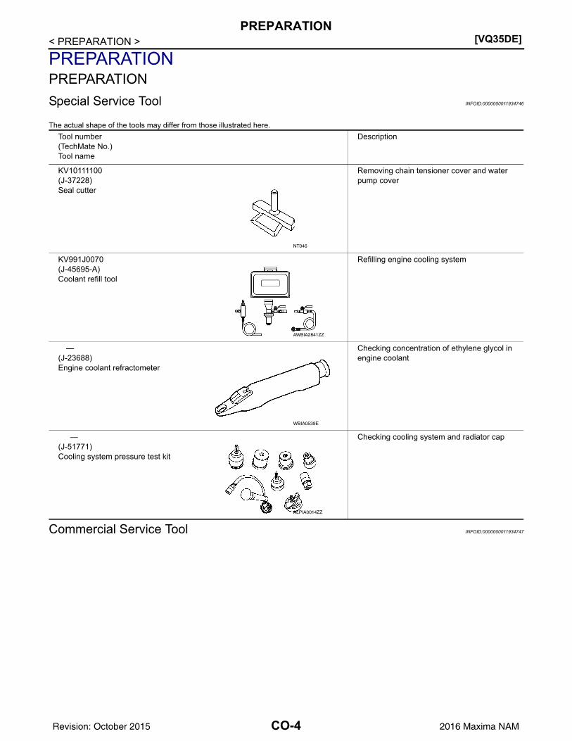
PREPARATIONPREPARATIONSpecial Service Tool INFOID:0000000011934746
The actual shape of the tools may differ from those illustrated here.
Commercial Service Tool INFOID:0000000011934747
Tool number(TechMate No.)Tool name
Description
KV10111100(J-37228)Seal cutter
Removing chain tensioner cover and water pump cover
KV991J0070(J-45695-A)Coolant refill tool
Refilling engine cooling system
—(J-23688)Engine coolant refractometer
Checking concentration of ethylene glycol in engine coolant
—(J-51771)Cooling system pressure test kit
Checking cooling system and radiator cap
NT046
AWBIA2841ZZ
WBIA0539E
ALPIA0014ZZ
CO-4Revision: October 2015 2016 Maxima NAM

PREPARATION[VQ35DE]
C
D
E
F
G
H
I
J
K
L
M
A
O
N
P
O
< PREPARATION >
C
Tool name Description
Power tool Loosening nuts, screws and bolts
—(J-33984-A)Radiator pressure adapter
Adapting cooling system pressure tester to ra-diator cap and reservoir tank capa: 28 (1.10) diameterb: 31.4 (1.236) diameterc: 41.3 (1.626) diameterUnit: mm (in)
Tube presser Pressing the tube of liquid gasket
PIIB1407E
S-NT564
S-NT052
CO-5Revision: October 2015 2016 Maxima NAM

[VQ35DE]OVERHEATING CAUSE ANALYSIS
< SYSTEM DESCRIPTION >
SYSTEM DESCRIPTIONOVERHEATING CAUSE ANALYSISTroubleshooting Chart INFOID:0000000011934748
Symptom Check items
Cooling sys-tem part malfunction
Poor heat transfer
Water pump malfunction Worn or loose drive belt
—
Thermostat stuck closed —
Damaged finsDust contamination or pa-per clogging
Physical damage
Clogged radiator cooling tube
Excess foreign material (rust, dirt, sand, etc.)
Reduced air flow
Cooling fan does not oper-ate.
Fan assembly —High resistance to fan rota-tion.
Damaged fan blades
Damaged radiator shroud — Radiator shroud —
Improper coolant mixture ratio —
Coolant viscosity—
Poor coolant quality — —
Insufficient coolant
Coolant leaks
Cooling hoseLoose clamp
Cracked hose
Water pump Poor sealing
Radiator capLoose radiator cap
Poor sealing
Radiator
O-ring for damage, deterio-ration or improper fitting
Cracked radiator tank
Cracked radiator core
Reservoir tank Cracked reservoir tank
Overflowing reservoir tank Exhaust gas leaks into cool-ing system
Cylinder head deterioration
Cylinder head gasket deteri-oration
CO-6Revision: October 2015 2016 Maxima NAM

OVERHEATING CAUSE ANALYSIS[VQ35DE]
C
D
E
F
G
H
I
J
K
L
M
A
O
N
P
O
< SYSTEM DESCRIPTION >
C
Except cool-ing system part mal-function
— Overload on engine
Abusive driving
High engine rpm under no load
Driving in low gear for ex-tended time
Driving at an extremely high speed
Powertrain system malfunc-tion
—Improper size of installed-wheels and tires
Dragging brakes
Improper ignition timing
Blocked or restricted air flow
Blocked bumper Blocked air flow
—
Blocked radiator grilleInstalled car brassiere
Mud contamination or paper clogging
Blocked radiator
Blocked air flowBlocked condenser
Installed large fog lamp
Symptom Check items
CO-7Revision: October 2015 2016 Maxima NAM

[VQ35DE]COOLING SYSTEM
< SYSTEM DESCRIPTION >COOLING SYSTEMCooling Circuit INFOID:0000000011934749
1. Cylinder block (RH) 2. Oil cooler 3. Cylinder head (RH)4. Water pump 5. Radiator 6. Water inlet7. Thermostat 8. Cylinder head (LH) 9. Cylinder block (LH)A. To heater B. To electric throttle control actuator C. From heaterD. From electric throttle control actuator
AWBIA1460ZZ
CO-8Revision: October 2015 2016 Maxima NAM

COOLING SYSTEM[VQ35DE]
C
D
E
F
G
H
I
J
K
L
M
A
O
N
P
O
< SYSTEM DESCRIPTION >
C
Schematic INFOID:0000000011934750
WBIA0562E
CO-9Revision: October 2015 2016 Maxima NAM

[VQ35DE]ENGINE COOLANT
< PERIODIC MAINTENANCE >
PERIODIC MAINTENANCEENGINE COOLANTSystem Inspection INFOID:0000000011934751
WARNING:• Do not remove the radiator cap or reservoir tank cap when the engine is hot. Serious burns could
occur from high-pressure engine coolant escaping from the cooling system.• When removing the radiator cap or reservoir tank cap, wrap a thick cloth around the cap and slowly
turn it a quarter turn to allow built-up pressure to escape. Then carefully remove the cap by turning itall the way.
CHECKING COOLING SYSTEM HOSESCheck hoses for the following:• Improper attachment• Leaks• Cracks• Dents• Bulges• Internal obstruction• Damage• Loose connections• Chafing• Deterioration
CHECKING RESERVOIR LEVEL• Check the coolant reservoir tank level when the engine is cool. • Adjust engine coolant level, if necessary, to ensure that the engine
coolant level is within the MIN to MAX range.CAUTION:Refill Genuine NISSAN Long Life Antifreeze/Coolant (blue) orequivalent in its quality mixed with water (distilled or deminer-alized). Refer to MA-16, "FOR USA AND CANADA : Fluids andLubricants" (United States and Canada) or MA-17, "FOR MEX-ICO : Fluids and Lubricants" (Mexico).
CHECKING COOLING SYSTEM FOR LEAKSWARNING:• Do not remove the radiator cap or reservoir tank cap when the engine is hot. Serious burns could
occur from high-pressure engine coolant escaping from the cooling system.• When removing the radiator cap or reservoir tank cap, wrap a thick cloth around the cap and slowly
turn it a quarter turn to allow built-up pressure to escape. Then carefully remove the cap by turning itall the way.
To check the cooling system for leaks, apply pressure to the coolingsystem using Tool (A).
CAUTION:Higher pressure testing than specified may cause radiator dam-age.
CHECKING RADIATOR CAPWARNING:
ALBIA1345ZZ
Tool number (A) : — (J-51771)Leakage test pressure : Refer to CO-28, "Radiator".
AWBIA2834ZZ
CO-10Revision: October 2015 2016 Maxima NAM

ENGINE COOLANT[VQ35DE]
C
D
E
F
G
H
I
J
K
L
M
A
O
N
P
O
< PERIODIC MAINTENANCE >
C
• Do not remove the radiator cap or reservoir tank cap when the engine is hot. Serious burns couldoccur from high-pressure engine coolant escaping from the cooling system.
• When removing the radiator cap or reservoir tank cap, wrap a thick cloth around the cap and slowlyturn it a quarter turn to allow built-up pressure to escape. Then carefully remove the cap by turning itall the way.
• Check the pressure valve of the radiator cap.- Replace the radiator cap if the metal plunger (B) on the pressure
valve cannot be seen around the edge of the rubber gasket (A).- Replace the radiator cap if there is damage or deposits of foreign
material on the rubber gasket or pressure valve.CAUTION:Thoroughly wipe out the radiator filler neck to remove anywaxy residue or foreign material.
• Check the negative-pressure valve of the radiator cap.- Replace the radiator cap if the negative-pressure valve does not
close completely when pulled open and released.- Replace the radiator cap if there is damage or deposits of foreign
material on the valve seat of the negative-pressure valve.- Replace the radiator cap if there is an abnormality in the operation
of the negative-pressure valve.
• Check radiator cap relief pressure.- Check the radiator cap relief pressure using Tool (A) and tool (B).
- When connecting the radiator cap to tool (B), apply water or cool-ant to the radiator cap seal surface.
- Replace the radiator cap if the radiator cap relief pressure is outside of specification.
CHECKING RADIATORCheck radiator for mud or clogging. If necessary, clean radiator as follows:CAUTION:• Be careful not to bend or damage the radiator fins.• When radiator is cleaned on-vehicle, remove surrounding parts in order to access the radiator core.
Tape the harness and electrical connectors to prevent water from entering.1. Spray water to the back side of the radiator core using a side-to-side motion from the top down. 2. Stop spraying when debris no longer flows from radiator core. 3. Blow air into the back side of radiator core using a side-to-side motion from the top down.
• Use compressed air lower than 490 kPa (5 kg/cm2, 71 psi) and keep a distance of more than 30 cm(11.8 in).
4. Continue to blow air until no water sprays out.5. Check for coolant leaks. Repair as necessary.
JPBIA0108ZZ
SMA967B
Tool number (A) : — (J-51771)Tool number (B)(commercially avail-able)
: — (J-33984-A or equivalent)
Radiator cap reliefpressure
: Refer to CO-28, "Radiator".
AWBIA2833ZZ
CO-11Revision: October 2015 2016 Maxima NAM

[VQ35DE]ENGINE COOLANT
< PERIODIC MAINTENANCE >Changing Engine Coolant INFOID:0000000011934752
WARNING:Do not remove the radiator cap when the engine is hot. Serious burns could occur from high-pressureengine coolant escaping from the radiator. Wrap a thick cloth around the cap. Slowly push down andturn it a quarter turn to allow built-up pressure to escape. Carefully remove the cap by pushing it downand turning it all the way.
DRAINING ENGINE COOLANT1. Remove the front under cover. Refer to EXT-26, "Removal and Installation".2. Open the radiator drain plug at the bottom of the radiator and remove the radiator filler cap. This is the
only step required when partially draining the cooling system (radiator only). CAUTION:• Do not allow the coolant to contact the drive belts. • Perform this step when engine is cold.
3. Remove water drain plug (A) and copper sealing washer (B). CAUTION:Do not reuse copper sealing washers.
4. Follow this step for heater core removal/replacement only. Disconnect the upper heater hose at theengine side and apply moderate air pressure [103.46 kPa (1.055 kg/cm2, 15 psi) maximum air pressure]into the hose for 30 seconds to blow the excess coolant out of the heater core.
5. When draining all of the coolant in the system, remove the reservoir tank and drain the coolant then cleanthe reservoir tank before installation.CAUTION:• Do not allow the coolant to contact the drive belts. • Perform this step when engine is cold.
6. When performing a complete cooling system drain, remove thewater drain plug (A), connector bolt (D), water drain plug (C) andwater drain plug O-ring (B) on the cylinder block.
CAUTION:Do not reuse water drain plug O-ring (B).NOTE:For Canada, connector bolt (D) is a block heater, not a water drainplug.7. Check the drained coolant for contaminants, such as rust, corro-
sion or discoloration.If the coolant is contaminated, flush the engine cooling system.
: Engine front
AWBIA1202GB
: Engine front
AWBIA2481ZZ
CO-12Revision: October 2015 2016 Maxima NAM

ENGINE COOLANT[VQ35DE]
C
D
E
F
G
H
I
J
K
L
M
A
O
N
P
O
< PERIODIC MAINTENANCE >
C
REFILLING ENGINE COOLANT1. Install the following, if removed:
• Cylinder block drain plugs, refer to EM-115, "Exploded View".• Reservoir tank, refer to CO-14, "Exploded View".• Cooling system hoses, refer to CO-14, "Exploded View"• Radiator drain plug, refer to CO-14, "Exploded View".
2. Set the vehicle heater controls to the full HOT and heater ON positions. Turn the vehicle ignition ON withthe engine OFF as necessary to activate the heater mode.
3. Fill the cooling system with engine coolant using Tool (A), follow-ing the manufacturer’s instructions included with the tool.
CAUTION:• Use recommended coolant or equivalent.• Do not use any cooling system additives such as radiator
sealer. Additives may clog the cooling system and causedamage to the engine, transmission or cooling system.
• The compressed air supply must be equipped with an airdryer.
4. Remove the Tool (A) and top off the cooling system with enginecoolant as necessary.
5. Install the radiator cap and reservoir tank cap.6. Run the engine until it reaches normal operating temperature.
CAUTION:Do not allow the engine to exceed normal operating temperature or engine damage may occur.
7. Stop the engine and allow it to cool.8. Check the engine coolant level and adjust if necessary.
FLUSHING COOLING SYSTEM1. Fill the radiator from the filler neck above the radiator upper hose and reservoir tank with clean water and
reinstall radiator filler cap. 2. Run the engine until it reaches normal operating temperature.3. Rev the engine two or three times under no-load.4. Stop the engine and wait until it cools down.5. Drain the water from the system. Refer to CO-12, "Changing Engine Coolant".6. Repeat steps 1-5 until clear water begins to drain from the radiator.
Tool number (A) : KV991J0070 (J-45695-A)Engine Coolant : Refer to MA-16, "FOR USA
AND CANADA : Fluids and Lu-bricants" (FOR USA AND CAN-ADA) or MA-17, "FOR MEXICO : Fluids and Lubricants" (FOR MEXICO).
AWBIA2842ZZ
CO-13Revision: October 2015 2016 Maxima NAM

[VQ35DE]RADIATOR
< REMOVAL AND INSTALLATION >
REMOVAL AND INSTALLATIONRADIATORExploded View INFOID:0000000011934753
Removal and Installation INFOID:0000000012248917
WARNING:Do not remove the radiator cap when the engine is hot. Serious burns could occur from high-pressureengine coolant escaping from the radiator. Wrap a thick cloth around the cap. Slowly turn it a quarterturn to allow built-up pressure to escape. Carefully remove the cap by turning it all the way.NOTE:• When removing components such as hoses, tubes/lines, etc., cap or plug openings to prevent fluid from
spilling.• The radiator hose clamps on the radiator hose (upper) and on the radiator hose (lower) are not serviced sep-
arately. Radiator hose clamps are part of the radiator hose assembly and serviced as one unit with the radi-ator hose.
REMOVAL1. Remove radiator cap and drain engine coolant from radiator. Refer to CO-12, "Changing Engine Coolant".
CAUTION:• Perform this step when the engine is cold.• Do not spill coolant on the drive belt.
1. Radiator 2. CVT oil cooler hose 3. O-ring4. Radiator drain plug 5. Radiator hose (lower) clamp 6. Radiator hose (lower)7. Reservoir hose (lower)
bracket8. Reservoir tank 9. Reservoir hose
10. Radiator cap 11. Radiator cap adapter 12. Radiator hose (upper)13. Radiator hose (upper) clamp A. To CVT B. To water outletC. To water inlet
AWBIA2739ZZ
CO-14Revision: October 2015 2016 Maxima NAM
RADIATOR[VQ35DE]
C
D
E
F
G
H
I
J
K
L
M
A
O
N
P
O
< REMOVAL AND INSTALLATION >
C
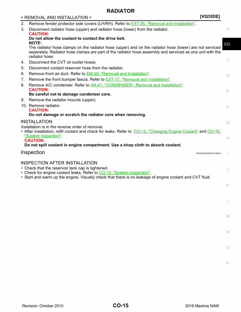
2. Remove fender protector side covers (LH/RH). Refer to EXT-28, "Removal and Installation".3. Disconnect radiator hose (upper) and radiator hose (lower) from the radiator.
CAUTION:Do not allow the coolant to contact the drive belt.NOTE:The radiator hose clamps on the radiator hose (upper) and on the radiator hose (lower) are not servicedseparately. Radiator hose clamps are part of the radiator hose assembly and serviced as one unit with theradiator hose.
4. Disconnect the CVT oil cooler hoses.5. Disconnect coolant reservoir hose from the radiator.6. Remove front air duct. Refer to EM-26, "Removal and Installation".7. Remove the front bumper fascia. Refer to EXT-17, "Removal and Installation".8. Remove A/C condenser. Refer to HA-41, "CONDENSER : Removal and Installation".
CAUTION:Be careful not to damage condenser core.
9. Remove the radiator mounts (upper).10. Remove radiator.
CAUTION:Do not damage or scratch the radiator core when removing.
INSTALLATIONInstallation is in the reverse order of removal.• After installation, refill coolant and check for leaks. Refer to CO-12, "Changing Engine Coolant" and CO-10,
"System Inspection". CAUTION:Do not spill coolant in engine compartment. Use a shop cloth to absorb coolant.
Inspection INFOID:0000000012248918
INSPECTION AFTER INSTALLATION• Check that the reservoir tank cap is tightened.• Check for engine coolant leaks. Refer to CO-10, "System Inspection".• Start and warm up the engine. Visually check that there is no leakage of engine coolant and CVT fluid.
CO-15Revision: October 2015 2016 Maxima NAM

[VQ35DE]COOLING FAN
< REMOVAL AND INSTALLATION >COOLING FANExploded View INFOID:0000000012248919
Removal and Installation INFOID:0000000012248920
WARNING:Do not remove the radiator cap when the engine is hot. Serious burns could occur from high-pressureengine coolant escaping from the radiator. Wrap a thick cloth around the cap. Slowly push down andturn it a quarter turn to allow built-up pressure to escape. Carefully remove the cap by pushing it downand turning it all the way.NOTE:When removing components such as hoses, tubes/lines, etc., cap or plug openings to prevent fluid from spill-ing.
REMOVAL1. Partially drain engine coolant from the radiator. Refer to CO-12, "Changing Engine Coolant".
CAUTION:• Perform when engine is cold.• Do not spill coolant on the drive belt.
2. Remove engine room cover. Refer to EM-25, "Removal and Installation".3. Remove air cleaner and air duct assembly. Refer to EM-26, "Removal and Installation".4. Remove battery tray and battery tray bracket. Refer to PG-101, "Removal and Installation (Battery)".5. Disconnect radiator hose (upper) from radiator.6. Disconnect the harness connectors from the fan motor.7. Remove fan shroud and motor assembly.
INSTALLATIONInstallation is in the reverse order of removal.
1. Radiator core support 2. Fan shroud and motor assembly 3. Grommet
AWBIA1275GB
CO-16Revision: October 2015 2016 Maxima NAM

COOLING FAN[VQ35DE]
C
D
E
F
G
H
I
J
K
L
M
A
O
N
P
O
< REMOVAL AND INSTALLATION >
C
• After installation, refill engine coolant and check for leaks. Refer to CO-12, "Changing Engine Coolant" andCO-10, "System Inspection".CAUTION:Do not spill coolant in engine compartment. Use a shop cloth to absorb coolant.
• Cooling fans are controlled by ECM. Refer to EC-541, "Diagnosis Procedure".
CO-17Revision: October 2015 2016 Maxima NAM

[VQ35DE]WATER PUMP
< REMOVAL AND INSTALLATION >WATER PUMPExploded View INFOID:0000000012248921
Removal and Installation INFOID:0000000012248922
WARNING:Do not remove the radiator cap when the engine is hot. Serious burns could occur from high-pressureengine coolant escaping from the radiator. Wrap a thick cloth around the cap. Slowly push down andturn it a quarter turn to allow built-up pressure to escape. Carefully remove the cap by pushing it downand turning it all the way.CAUTION:• When removing water pump assembly, be careful not to get coolant on drive belt.• Water pump cannot be disassembled and must be replaced as a unit.• After installing the water pump, connect hose and clamp securely, then check for leaks. Repair as
necessary. NOTE:When removing components such as hoses, tubes/lines, etc., cap or plug openings to prevent fluid from spill-ing.
REMOVAL1. Disconnect the negative battery terminal. Refer to PG-101, "Removal and Installation (Battery)".2. Remove front air duct. Refer to EM-26, "Removal and Installation".3. Remove cowl top extension. Refer to EXT-25, "Removal and Installation".4. Remove front undercover. Refer to EXT-26, "Removal and Installation".5. Drain coolant from the radiator. Refer to CO-12, "Changing Engine Coolant".
CAUTION:Perform when the engine is cold.
6. Disconnect coolant reservoir hose and remove coolant reservoir tank. Refer to CO-14, "Exploded View".7. Drain the power steering fluid reservoir. Refer to ST-29, "Draining and Refilling".8. Remove the power steering oil pump. Refer to ST-43, "Removal and Installation".
1. Timing chain tensioner (primary) 2. Valve timing control cover gasket (bank 1)
3. Valve timing control cover (bank 1)
4. Water pump cover 5. O-ring 6. O-ring (Identify with white mark)7. Water pump A. Apply engine oil B. Apply engine coolant.
ALBIA1350ZZ
CO-18Revision: October 2015 2016 Maxima NAM

WATER PUMP[VQ35DE]
C
D
E
F
G
H
I
J
K
L
M
A
O
N
P
O
< REMOVAL AND INSTALLATION >
C
9. Support the engine (1) and transaxle (2) using suitable jack (A).CAUTION:• Position a suitable jack under the engine and transaxle
assembly as shown. • Do not damage the front exhaust tube or transaxle oil pan
with the jack.
10. Remove The RH engine insulator and bracket. Refer to EM-103, "ENGINE MOUNT (REAR) : Removaland Installation".
11. Remove the drive belt auto-tensioner assembly. Refer to EM-18, "Removal and Installation of Drive BeltAuto-tensioner".
12. Set No. 1 cylinder at TDC on its compression stroke.• Align pointer with TDC mark on crankshaft pulley.
13. Remove water drain plug (A) and copper sealing washer (B) todrain coolant from engine.CAUTION:Do not reuse copper sealing washers.
14. Disconnect valve timing control harness connectors and remove valve timing control cover (bank 1). Referto EM-55, "Valve Timing Control Cover (bank 1)".
15. Remove water pump cover. Refer to EM-58, "Exploded View".16. Remove the timing chain tensioner (primary) as follows:a. Pull the lever (C) down to release the plunger stopper tab (B).b. Insert the stopper pin (A) into the tensioner body hole to hold the
lever (C) and keep the plunger stopper tab (B) released.NOTE:An allen wrench [(1.2 mm (0.047 in)] is used for a stopper pin(A) as an example.
c. Compress the plunger (D) into the tensioner body (1) by press-ing the slack guide (2).
d. Keep the slack guide (2) pressed and lock the plunger (D) in bypushing the stopper pin (A) through the lever (C) and into thechain tensioner body hole.
e. Remove timing chain tensioner bolts and then remove the timing chain tensioner.CAUTION:Be careful not to drop timing chain tensioner bolts inside timing chain case.
ALBIA0894GB
: Front
AWBIA1202GB
AWBIA0903ZZ
CO-19Revision: October 2015 2016 Maxima NAM

[VQ35DE]WATER PUMP
< REMOVAL AND INSTALLATION >17. Remove the three water pump bolts (A). Make a gap between
water pump sprocket (1) and timing chain by carefully turningcrankshaft pulley (2) counterclockwise until timing chain loosenson water pump sprocket (1).CAUTION:Be careful not to drop water pump bolts inside the timingchain case.
18. Screw M8 bolts [pitch: 1.25 mm (0.49 in) length: approx. 50 mm(1.97in)] into water pumps upper and lower bolt holes until theyreach the timing chain case.
19. Hold the timing chain to the side using a suitable tool and alter-nately tighten the M8 bolts for a half turn until the water pumpcan be removed.CAUTION:• Place a suitable shop cloth below the water pump hous-
ing to prevent any engine coolant from dripping into thetiming chain case.
• Remove water pump without causing sprocket to contacttiming chain. It may be necessary to adjust the timingchain until it loosens enough to remove the water pump.
• Pull water pump straight out while preventing vane fromcontacting the engine block and timing chain case.
20. Remove M8 bolts and O-rings from water pump.CAUTION:Do not reuse O-rings.
INSPECTION AFTER REMOVAL• Visually check for significant dirt or rust on the water pump body
and vane.• Check that the vane shaft turns smoothly by hand and is not
excessively loose.• Replace the water pump assembly if the water pump does not per-
form properly.
INSTALLATION
AWBIA0904ZZ
JLC357B
AWBIA2670ZZ
SLC943A
CO-20Revision: October 2015 2016 Maxima NAM

WATER PUMP[VQ35DE]
C
D
E
F
G
H
I
J
K
L
M
A
O
N
P
O
< REMOVAL AND INSTALLATION >
C
1. Install new O-rings to water pump (1).CAUTION:Do not reuse O-rings.
a. Apply engine oil to the O-rings (2,3) as shown.b. Locate the O-ring (2) with white paint mark (A) to engine front
side.
2. Hold timing chain to the side ( ) and install the water pump( ).CAUTION:• Install water pump without causing sprocket to contact
timing chain. It may be necessary to adjust the timingchain until it loosens enough to install the water pump.
• Install water pump straight in while preventing vane fromcontacting the engine block and timing chain case.
• Be careful not to damage the O-rings when installing thewater pump.
• Check that timing chain and water pump sprocket areengaged.
• Tighten water pump bolts alternately and evenly to specification.
3. Remove dust and foreign material completely from installation area of timing chain tensioner and rear tim-ing chain case.
4. Turn the crankshaft pulley approximately 20° clockwise so thatthe timing chain on the timing chain tensioner side is loose.
5. Apply engine oil to the oil feed hole and timing chain tensioner and install the timing chain tensioner.6. Remove the stopper pin (A).
7. Install valve timing control cover (bank 1) and water pump cover.a. Before installing, remove all traces of liquid gasket from mating surface of water pump cover and IVT
cover using a scraper.Also remove traces of liquid gasket from the mating surface of the front cover.
AWBIA1290GB
SLC031B
PBIC0848E
AWBIA0905ZZ
CO-21Revision: October 2015 2016 Maxima NAM

[VQ35DE]WATER PUMP
< REMOVAL AND INSTALLATION >b. Using Genuine RTV Silicone Sealant or equivalent, apply a continuous bead of liquid gasket to mating
surface of IVT cover and water pump cover. Refer to GI-22, "Recommended Chemical Products andSealants".CAUTION:• Installation should be done within 5 minutes after applying liquid gasket.• Do not fill the engine with oil for at least 30 minutes after the components are installed to allow
the sealant to cure.8. Install water drain plug (A) and copper sealing washer (B).
CAUTION:Do not reuse copper sealing washers.
9. Installation of remaining components is in the reverse order of removal.• After installation, refill coolant and check for leaks. Refer to CO-12, "Changing Engine Coolant" and CO-
10, "System Inspection".CAUTION:Do not spill coolant in engine compartment. Use a shop cloth to absorb coolant.
• After starting engine, let idle for three minutes, then rev engine up to 3,000 rpm no-load to purge air from the high-pressure chamber of the chain tensioner. The engine may produce arattling noise. This indicates that air still remains in the chamber and is not a matter of concern.
INSPECTION AFTER INSTALLATION• Before starting engine, check oil/fluid levels including engine coolant and engine oil. If the levels are less
than required quantity, fill to the specified level. Refer to MA-16, "FOR USA AND CANADA : Fluids andLubricants" (For USA and Canada) or MA-17, "FOR MEXICO : Fluids and Lubricants" (For Mexico).
• Use procedure below to check for fuel leakage.• Turn ignition switch ON (with engine stopped). With fuel pressure applied to fuel piping, check for fuel leak-
age at connection points.• Start engine. With engine speed increased, check again for fuel leakage at connection points.• Run engine to check for unusual noise and vibration.
NOTE:If hydraulic pressure inside timing chain tensioner drops after removal and installation, slack in the guidemay generate a pounding noise during and just after engine start. However, this is normal. Noise will stopafter hydraulic pressure rises.
• Warm up engine thoroughly to make sure there is no leakage of fuel, exhaust gas, or any oils/fluids includingengine oil and engine coolant.
• Bleed air from passages in lines and hoses, such as in cooling system.• After cooling down engine, again check oil/fluid levels including engine oil and engine coolant. Refill to spec-
ified level if necessary.• Summary of the inspection items:
*Power steering fluid, brake fluid, etc.
: Front
Water drain plug (A) : Refer to CO-12, "Changing Engine Coolant".
AWBIA1202GB
Item Before starting engine Engine running After engine stopped
Engine coolant Level Leakage Level
Engine oil Level Leakage Level
Transmission/transaxle fluid CVT models Leakage Level/Leakage Leakage
Other oils and fluids* Level Leakage Level
Fuel Leakage Leakage Leakage
Exhaust gas — Leakage —
CO-22Revision: October 2015 2016 Maxima NAM

THERMOSTAT AND THERMOSTAT HOUSING[VQ35DE]
C
D
E
F
G
H
I
J
K
L
M
A
O
N
P
O
< REMOVAL AND INSTALLATION >
C
THERMOSTAT AND THERMOSTAT HOUSINGExploded View INFOID:0000000012248923
Removal and Installation INFOID:0000000012248924
REMOVALWARNING:Do not remove the radiator cap when the engine is hot. Serious burns could occur from high-pressureengine coolant escaping from the radiator. Wrap a thick cloth around the cap. Slowly push down andturn it a quarter turn to allow built-up pressure to escape. Carefully remove the cap by pushing it downand turning it all the way.NOTE:When removing components such as hoses, tubes/lines, etc., cap or plug openings to prevent fluid from spill-ing.1. Drain engine coolant from the radiator. Refer to CO-12, "Changing Engine Coolant".
CAUTION:Perform when engine is cool.
2. Remove cowl top extension. Refer to EXT-25, "Removal and Installation".3. Remove front air duct. Refer to EM-26, "Removal and Installation".4. Remove coolant reservoir hose.5. Remove coolant reservoir tank. Refer to CO-14, "Exploded View".6. Drain the power steering fluid reservoir. Refer to ST-29, "Draining and Refilling".7. Remove the power steering oil pump. Refer to ST-43, "Removal and Installation".8. Support the engine (1) and transaxle (2) using suitable jack (A).
CAUTION:• Position a suitable jack under the engine and transaxle
assembly as shown. • Do not damage the front exhaust tube or transaxle oil pan
with the jack.
AWBIA2759ZZ
1. Gasket 2. Thermostat assembly
ALBIA0894GB
CO-23Revision: October 2015 2016 Maxima NAM

[VQ35DE]THERMOSTAT AND THERMOSTAT HOUSING
< REMOVAL AND INSTALLATION >9. Remove The RH engine insulator and bracket. Refer to EM-103, "ENGINE MOUNT (REAR) : Removal
and Installation".10. Disconnect radiator hose (lower).11. Remove engine coolant inlet thermostat assembly and gasket.
• Do not disassemble engine coolant inlet and thermostat.Replace them as a unit if necessary.
• Do not reuse gasket.
INSPECTION AFTER REMOVAL• Place a thread so that it is caught in the valves of the thermostat.
Immerse fully in a container filled with water. Heat while stirring. • The valve opening temperature is the temperature at which the
valve opens and the thermostat falls from the thread.• Continue heating. Check the full-open lift amount.
NOTE:The full-open lift amount standard temperature for the thermostat isthe reference value.
• After checking the full-open lift amount, lower the water tempera-ture and check the valve closing temperature.
• If valve setting at measured values is out of standard range, replace thermostat.
INSTALLATIONInstallation is in the reverse order of removal.• Install thermostat with jiggle valve facing upward.• After installation, refill engine coolant and check for leaks. Refer to
CO-12, "Changing Engine Coolant" and CO-10, "System Inspec-tion".CAUTION:• Do not spill coolant in engine compartment. Use a shop
cloth to absorb coolant.• Do not reuse gasket.
SLC962AA
SLC949A
Thermostat Standard Values
Valve opening temperature Refer to CO-28, "Thermostat".
Full-open lift amount Refer to CO-28, "Thermostat".
Valve closing temperature Refer to CO-28, "Thermostat".
SLC948A
CO-24Revision: October 2015 2016 Maxima NAM

WATER OUTLET AND WATER PIPING[VQ35DE]
C
D
E
F
G
H
I
J
K
L
M
A
O
N
P
O
< REMOVAL AND INSTALLATION >
C
WATER OUTLET AND WATER PIPINGExploded View INFOID:0000000012482757
Removal and Installation INFOID:0000000011934759
WARNING:Do not remove the radiator cap when the engine is hot. Serious burns could occur from high pressureengine coolant escaping from the radiator. Wrap a thick cloth around the radiator cap. Slowly turn it aquarter of a turn to release built-up pressure. Carefully remove radiator cap by turning it all the way.NOTE:When removing components such as hoses, tubes/lines, etc., cap or plug openings to prevent fluid from spill-ing.
REMOVALCAUTION:Perform when the engine is cold.1. Remove the engine room cover. Refer to EM-25, "Removal and Installation".2. Partially drain coolant from radiator. Refer to CO-12, "Changing Engine Coolant".
1. Heater hose 2. Clamp 3. Water hose4. Clamp 5. Water outlet 6. Gasket7. Gasket 8. Water connector 9. O-ring10. Water bypass pipe 11. Clamp 12. Water hose13. Heater pipe 14. Water hose 15. Heater hose16. Engine coolant temperature sensor 17. Clamp 18. Radiator hose (upper)A. To heater core B. To electric throttle control actuator C. To oil coolerD. To radiator
AWBIA2729ZZ
CO-25Revision: October 2015 2016 Maxima NAM

[VQ35DE]WATER OUTLET AND WATER PIPING
< REMOVAL AND INSTALLATION >3. Remove front air duct. Refer to EM-26, "Removal and Installation".4. Remove the air duct and air cleaner assembly. Refer to EM-26, "Removal and Installation".5. Remove the front fender protector side cover (RH/LH). Refer to EXT-28, "Removal and Installation".6. Disconnect the hoses from the electric throttle control actuator.7. Disconnect coolant hoses.8. Remove upper radiator hose and heater hoses.9. Remove connector(s) from heater pipe.10. Disconnect the harness connector from engine coolant temperature sensor.11. Remove water outlet, heater pipe, water connector, and water bypass pipe nuts and bolts.12. Remove the engine coolant temperature sensor if necessary.
INSTALLATION1. Installation is in the reverse order of removal.
• Securely insert each hose, and install a clamp at a position where it does not interfere with the pipebulge.CAUTION:Do not reuse gasket.
• When inserting heater pipe and water bypass pipe into water connector, apply neutral detergent to newO-rings.CAUTION:Do not reuse O-rings.
• After installation, refill engine coolant and check for leaks. Refer to CO-10, "System Inspection".
CO-26Revision: October 2015 2016 Maxima NAM

COOLING FAN[VQ35DE]
C
D
E
F
G
H
I
J
K
L
M
A
O
N
P
O
< UNIT DISASSEMBLY AND ASSEMBLY >
C
UNIT DISASSEMBLY AND ASSEMBLYCOOLING FANDisassembly and Assembly of Cooling Fan INFOID:0000000011934760
DISASSEMBLY1. Remove fan blade nut.2. Remove fan blade from fan motor.3. Remove fan motor bolts and remove fan motor from fan shroud.
ASSEMBLYAssembly is in the reverse order of disassembly.
AWBIA0739GB
1. Fan blade 2. Fan shroud 3. Fan motor
CO-27Revision: October 2015 2016 Maxima NAM

[VQ35DE]SERVICE DATA AND SPECIFICATIONS (SDS)
< SERVICE DATA AND SPECIFICATIONS (SDS)
SERVICE DATA AND SPECIFICATIONS (SDS)SERVICE DATA AND SPECIFICATIONS (SDS)Capacity INFOID:0000000011934761
(US qt, Imp qt)
Thermostat INFOID:0000000011934762
Radiator INFOID:0000000011934763
Unit: kPa (kg/cm2, psi)
Coolant capacity (with reservoir tank at MAX level) 9.2 (9-3/4, 8-1/8)
Valve opening temperature 82°C (180°F)
Full-open lift amount 8.6 mm / 95°C (0.339 in / 203°F)
Valve closing temperature 77°C (171°F)
Radiator cap relief pressure Standard 122.3 – 151.7 (1.3 – 1.5, 17.7 – 22)
Leakage test pressure 156 (1.6, 23)
CO-28Revision: October 2015 2016 Maxima NAM


![[WUC 2016] Kristjan Hauksson, Co-Founder and COO, SMFB Engine | Introduction](https://img.dokumen.tips/doc/110x75/58cef7e11a28abab738b5277/wuc-2016-kristjan-hauksson-co-founder-and-coo-smfb-engine-introduction.jpg)