Embed Size (px)
Citation preview

Engineering DRG practice
- A Refresher Course -
PDF created with pdfFactory trial version www.pdffactory.com

Engineering DRG practice
Introduction:What is Engineering Drawing?
• DRG is the language of Engineers.• It is the principal means of communication in ENGG.• It is the method used to impart ideas, convey
information, specify shape, configuration and size.• It is an international language and is bound, like any
other language, by rules and conventions.
PDF created with pdfFactory trial version www.pdffactory.com

Engineering DRG practice
• Projections• DRG standards• Sheet sizes• Folding• Filing
PDF created with pdfFactory trial version www.pdffactory.com

Picture planes :
Engineering DRG practice
PDF created with pdfFactory trial version www.pdffactory.com

Projections:• Projection is the representation on a plane surface the image of
an object observed by a viewer.• In graphical language shape is described by projections as
geometric figures. • The image of the object, formed by rays of sight (lines of projection)
taken in some particular direction from the object on to a plane form a view in any DRG.
Engineering DRG practice
PDF created with pdfFactory trial version www.pdffactory.com

Orthographic projection:
• It is a particular type of projection in which the object’s image is
projected onto three mutually perpendicular planes.• If the viewing point (eye) is at an infinite distance from the object
such that the projection lines are parallel to one another and perpendicular to the picture plane, the projection obtained is called
Orthographic projection.
• It represents the exact shape of a three dimensional object on a two dimensional sheet in two or more views.
Engineering DRG practice
PDF created with pdfFactory trial version www.pdffactory.com

Orthographic projection: contd…
• These views require good imagination to interpret and visualize
the details of objects
• This method is universally used in ENGG DRG to represent objects.
• Orthographic views are required for the manufacture of objects
and machine parts.
• Front view, top view and Side view of an object are the principal
Orthographic views.
• Two types of Orthographic projections are used:
- First angle projection
- Third angle projection
Engineering DRG practice
PDF created with pdfFactory trial version www.pdffactory.com

First angle projection :
Engineering DRG practice
PDF created with pdfFactory trial version www.pdffactory.com

First angle projection :1. Object is kept above the H.P and in front of V.P. (i.e. in the
first quadrant).2. The object is projected on the V.P. and the H.P. 3. The object lies between the observer and the plane of
projection. 4. H.P. is then rotated in clockwise direction through 900 such
that the V.P. and the H.P. are brought in line with each other.5. In this projection method, the top view appears below the
front view and left side view appears on the right of the front view.
Engineering DRG practice
PDF created with pdfFactory trial version www.pdffactory.com

Third angle projection :
Engineering DRG practice
PDF created with pdfFactory trial version www.pdffactory.com

Third angle projection :1. Object is kept behind the V.P. and below the H.P. (i.e. in the
third quadrant).2. The projection plane lies between the observer and the
object.3. The projection planes are assumed to be transparent.4. The object is projected on the V.P. and the H.P. 5. H.P. is then rotated in clockwise direction through 900 such
that the V.P. and the H.P. are brought in line with each other.6. In this projection method, the top view appears above the
front view and left side view appears on the left of the front view.
Engineering DRG practice
PDF created with pdfFactory trial version www.pdffactory.com

Other types of projections:
• Oblique
• Isometric
• Perspective
Note: 1. Oblique and Isometric views are often used in the preparation of maintenance manuals and parts lists of ENGG equipment / assemblies.
2. Perspective views are mostly used by artists.
Engineering DRG practice
PDF created with pdfFactory trial version www.pdffactory.com

Other types of projections: contd…
Oblique Projection:
• It has two axes at right angles to each other.
• The third axis may be at any angle to the horizontal, 300 or 450
are being generally used.
• The measurement along the third axis are halved.
Engineering DRG practice
PDF created with pdfFactory trial version www.pdffactory.com

Other types of projections: contd…
Isometric Projection:
• It is a special type of pictorial projection showing the three
DIM of an object in one view.
• It conveys the real shape of the object.
• Isometric projection of any object is the single orthographic
projection of the object placed so that all its three axes are
equally inclined to the plane of projection.
• In this position, all the three sides of the object are exposed to
the viewer.
• Isometric scale = 0.815 x True length
Engineering DRG practice
PDF created with pdfFactory trial version www.pdffactory.com

DRG Standards
Engineering DRG practice
PDF created with pdfFactory trial version www.pdffactory.com

The following are some of the BIS standards relevant to Engineering DRG practice :
• These standards are reviewed and revised from time to time• IS:10714 - 1983 – General principles of presentation on technical
drawings• IS:9609 (part1)-1983 – Lettering on technical drawings (part1 English
characters)• IS:10718-1983 – Method of dimensioning and tolerancing on technical
drawings• IS:11667 – 1991 – Technical drawings - Linear and angular tolerancing
- Indication on drawings• IS:11669 -1986 – General principle of dimensioning on technical
drawings• IS:8000(Part1)-1985 - Geometrical tolerancing on technical drawings
(part 1: Tolerancing of form, orientation, location and run-out and appropriate geometrical definitions)
Engineering DRG practice
PDF created with pdfFactory trial version www.pdffactory.com

BIS standards for technical DRG: contd…
• IS:8000 (Part2)-1976 - Geometrical tolerancing on technical drawings (part 2: Maximum material principles)
• IS:8000 (Part3)-1985 - Geometrical tolerancing on technical drawings (part 3: Dimensioning and tolerancing of profiles)
• IS:10721 – 1983 - Datum and datum systems for geometrical tolerancing on technical drawings
• IS:11158-1984 - Proportions and dimensions of symbols for geometrical tolerancing used in technical drawings
• IS:2709-1964 - Guide for selection of fits• IS:919:1963 - Recommendations for Limits and Fits for Engg• IS:3073 -1967 - Assessment of surface roughness• IS:10719 - Method of indicating surface texture on tech DRG
Engineering DRG practice
PDF created with pdfFactory trial version www.pdffactory.com

BIS standards for technical DRG: contd…
• IS: 813- 1986 - Scheme of symbols for welding• IS: 10711-1983 - Sizes of DRG sheets• IS: 1064 - 1961 - Specification for paper sizes.
Engineering DRG practice
PDF created with pdfFactory trial version www.pdffactory.com
Sheet sizes
Engineering DRG practice
PDF created with pdfFactory trial version www.pdffactory.com

DRG sheet sizePreferred DRG sheet sizes are as follows:
210 X 297A4
297 X 420A3
420 X 594A2
594 X 841A1
841 X 1189A0
Trimmed size in mmSheet size
Engineering DRG practice
• The surface area of two successive preferred sizes are in the ratio of 1:2.• DRG sheet sides of each size are in the ratio of 1:√2• The surface area of the basic size A0 is 1 sq. m
PDF created with pdfFactory trial version www.pdffactory.com

Engineering DRG practice
Similarity of formats Relationship between two sides
Successive format sizes
Preferred DRG sheet sizes
PDF created with pdfFactory trial version www.pdffactory.com

Title BlockTitle block should contain the following information:1. Title of the DRG2. DRG No. & sheet No.3. Scale4. Projection symbol5. Name of the organisation6. Dated initials of the personnel designing, checking,
standard and approvedNote:
The size of the title block is uniform for all sizes.
Engineering DRG practice
PDF created with pdfFactory trial version www.pdffactory.com

Recommended scales for Engineering DRG:Full size Reduced scale Enlarged scale
1:1 1:2 50:11:5 20:11:10 10:11:20 5:11:50 2:11:1001:2001:5001:10001:20001:50001:10000
Engineering DRG practice
PDF created with pdfFactory trial version www.pdffactory.com

Grid reference on DRG sheet:
• It permits easy location on the DRG of details, additions, modifications etc.
1. How & when to use Grid reference ? eg: C7
E5
Engineering DRG practice
PDF created with pdfFactory trial version www.pdffactory.com

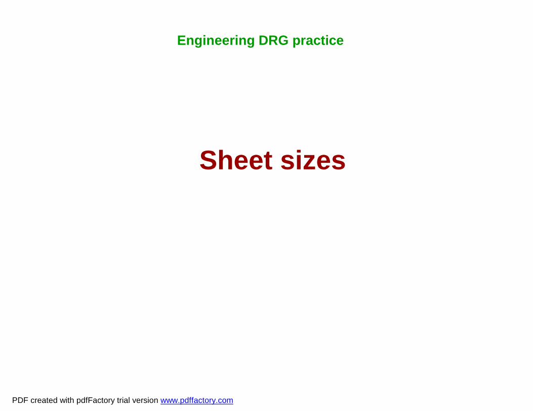
Conventional lines and applications
C1 Limits of partial or interrupted views and sections, if the limit is not a chain thin lineD1
C
D
Continuous thin free hand.Continuous thin (Straight) with zig zags.
B1 Imaginary lines of intersectionB2 DIM linesB3 Projection linesB4 Leader lines
B5 HatchingB6 Out lines of revolved section
in placeB7 Short centre line
BContinuous - thin ( Straight and curved)
A1 Visible outline A2 Visible edges
AContinuous - thick
ApplicationsLineDescription
Engineering DRG practice
PDF created with pdfFactory trial version www.pdffactory.com
Conventional lines and applicationsApplicationsLineDescription
J1 Indication of lines or surfaces to which a special requirement applies
J Chain thick
H1 Cutting planesHChain thin, thick at ends and changes of direction
G1 Centre linesG2 Lines of symmetryG3 Trajectories
GChain thin
E1 Hidden outlinesE2 Hidden edgesF1 Hidden outlinesF2 Hidden edges
E
F
Dashed thick
Dashed thin
Engineering DRG practice
PDF created with pdfFactory trial version www.pdffactory.com

Conventional lines and applications
K1 Outlines of adjacent parts
K2 Alternative and extreme positions of movable parts
K3 Centroidal linesK4 Initial outlines prior to
formingK5 Parts situated in front of
the cutting plane
KChain thin double dashed
ApplicationIllustrationType of line
Engineering DRG practice
• Line thicknesses recommended: 0.18, 0.25, 0.35, 0.5, 0.7, 1.0, 1.4 and 2.0
Note: Due to reproduction problems 0.18 is normally avoided
PDF created with pdfFactory trial version www.pdffactory.com

Lettering
Engineering DRG practice
PDF created with pdfFactory trial version www.pdffactory.com

Engineering DRG practice
Lettering proportions
PDF created with pdfFactory trial version www.pdffactory.com

Engineering DRG practice
Lettering proportions
PDF created with pdfFactory trial version www.pdffactory.com

Engineering DRG practice
Lettering proportions
PDF created with pdfFactory trial version www.pdffactory.com
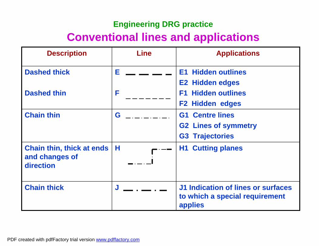
Engineering DRG practice
Different characteristics of lettering type ‘A’
PDF created with pdfFactory trial version www.pdffactory.com

Engineering DRG practice
Different characteristics of lettering type ‘B’
PDF created with pdfFactory trial version www.pdffactory.com

DRG sheet Folding and Filing:• There are two methods of folding of DRG prints.
1. The first method is for DRG prints to be filed or bound.2. The second method is intended for prints to be kept
individually in filing cabinet.Basic principles:§ All large prints of sizes higher than A4 are folded to A4 sizes.§ The title block of a folded print as it appears in the bottom
right corner shall be visible outer most after folding.§ Suitable folding marks are to be introduced in the DRG
sheets as guide for folding purpose.
Engineering DRG practice
PDF created with pdfFactory trial version www.pdffactory.com

Engineering DRG practice
Folding of prints for filing or binding
PDF created with pdfFactory trial version www.pdffactory.com
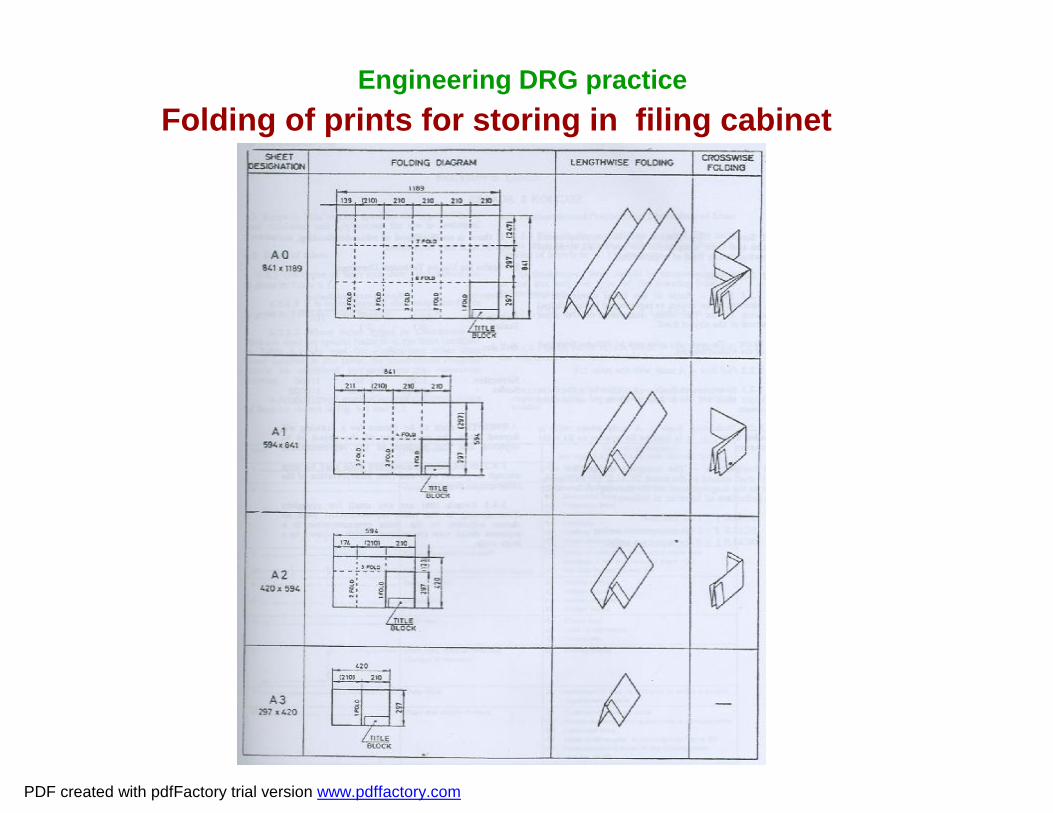
Engineering DRG practiceFolding of prints for storing in filing cabinet
PDF created with pdfFactory trial version www.pdffactory.com

• Types of drawings• Contents of a drawing
Engineering DRG practice
PDF created with pdfFactory trial version www.pdffactory.com

Types of drawings1. Design layout:Shows the arrangement of various assemblies and parts in their correct orientation and location as envisaged by the designer and drawn to scale.2. Assembly drawing:Contains all the components and sub-assemblies which are shown in the correctly fitted condition and demanded item wise and number wise. The specifications for standard parts and proprietary items are also given in the assembly drawing.3. Item List:Accompanies the assembly drawings as a separate sheet/sheets. Some times this is incorporated in the assembly drawing itself.
Engineering DRG practice
PDF created with pdfFactory trial version www.pdffactory.com

Types of drawings4. Part drawing:Contains enough technical data to fully define the individual component and facilitate its manufacture.5. Manufacturing drawing:Contains process information for the manufacture of an assembly or individual component. It is often made as a separate drawing.In some cases process information is carried in the product drawing itself whether assembly or component.
Engineering DRG practice
PDF created with pdfFactory trial version www.pdffactory.com

Types of drawings6. Technical Documents:
These are strictly speaking not drawings but they come within the purview of a product design office. Some of them contain drawings /sketches in 2D or 3D form to facilitate easy understanding by the user. These include:• Product specifications• Consolidated Complete Equipment Schedule (CCES)• Operators/users manual• Maintenance/repair manuals• Illustrated Spare Parts List (ISPL)• Manufacturer’s Recommended List of Spares (MRLS)• Maintenance Scales (MS)• Training Charts
Engineering DRG practice
PDF created with pdfFactory trial version www.pdffactory.com

Contents of a drawing
• A DRG contains technical information in the form of Orthographic views, text and symbols.
• It gives detailed data with regard to dimensions, permissible deviations, material, surface finish, protective coatings, assembly procedures, part details, specifications, process information, etc depending upon the type of drawing.
• Drawings are made in standard sheet sizes from A4 to A0 with the title block of the organisation and numbered according to a specific system followed. The title block also contains information in type of projection method used, scale and standard notes.
Engineering DRG practice
PDF created with pdfFactory trial version www.pdffactory.com

Dimensions and Tolerances
Engineering DRG practice
PDF created with pdfFactory trial version www.pdffactory.com
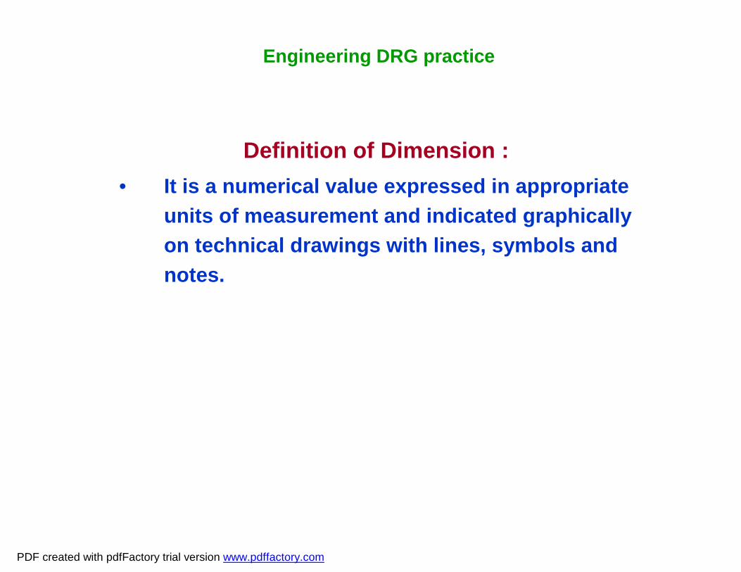
Definition of Dimension : • It is a numerical value expressed in appropriate
units of measurement and indicated graphically on technical drawings with lines, symbols and notes.
Engineering DRG practice
PDF created with pdfFactory trial version www.pdffactory.com

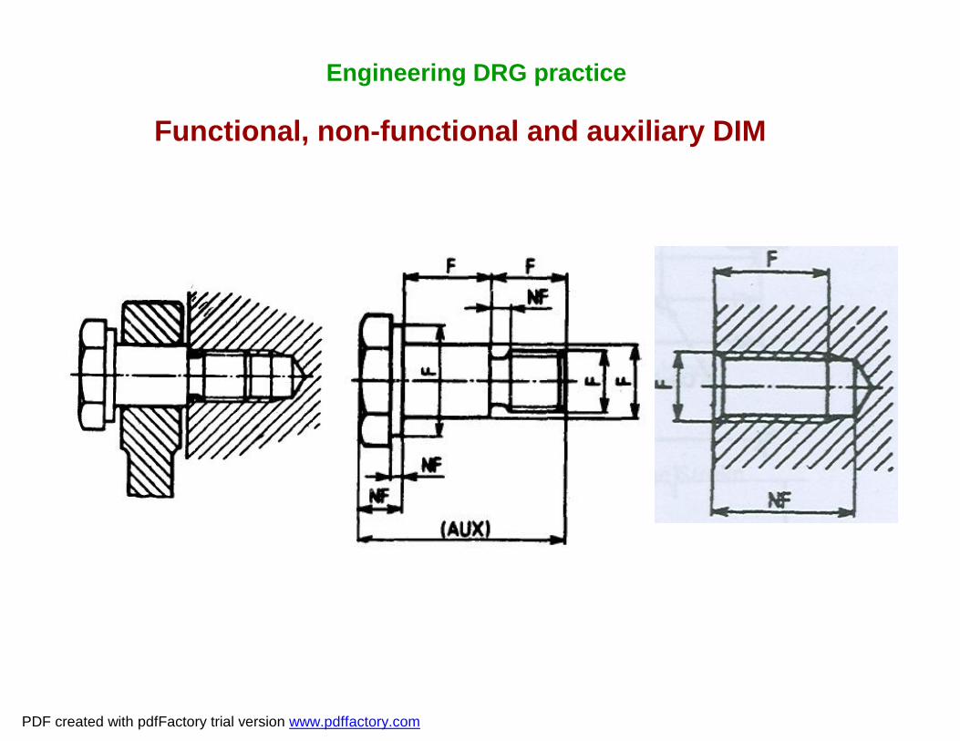
Dimension Classifications:• Functional dimensions:• Any DIM that is essential for the functioning of
the component or the equipment.• Non Functional dimensions:• Auxiliary dimensions:• It does not govern production or Inspection and
is derived from other values shown on drgs.
Engineering DRG practice
PDF created with pdfFactory trial version www.pdffactory.com
Engineering DRG practice
Functional, non-functional and auxiliary DIM
PDF created with pdfFactory trial version www.pdffactory.com

System of dimensioning:1. Method 12. Method 21. Method 1 : - Aligned system• DIM values are so placed that they may be read from the
bottom or right hand edge of the DRG2. Method 2 : - Unidirectional system• DIM values are so placed that they may be read from the
bottom edge DRG sheet• It is more convenient in large size DRG
Engineering DRG practice
PDF created with pdfFactory trial version www.pdffactory.com

Method 1 : - Aligned system
Engineering DRG practice
PDF created with pdfFactory trial version www.pdffactory.com

Method 2 : - Unidirectional system
Engineering DRG practice
PDF created with pdfFactory trial version www.pdffactory.com
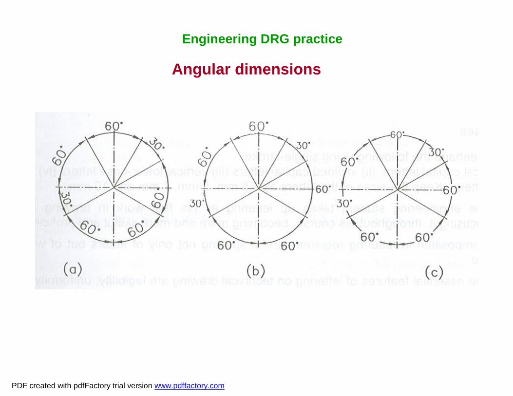
Angular dimensions
Engineering DRG practice
PDF created with pdfFactory trial version www.pdffactory.com

Elements of dimensioning:
1. Projection line or Extension line2. Dimensional line3. Leader line4. Dimension line termination5. The origin indication6. Dimension itself
Engineering DRG practice
PDF created with pdfFactory trial version www.pdffactory.com

Elements of dimensioning:
Engineering DRG practice
PDF created with pdfFactory trial version www.pdffactory.com

Arrangement and indication of dimensions:
1. Chain dimensioning2. Parallel dimensioning3. Super imposed running dimensioning4. Equidistant features5. Dimensioning by coordinates
Engineering DRG practice
PDF created with pdfFactory trial version www.pdffactory.com

Chain dimensioning
Engineering DRG practice
PDF created with pdfFactory trial version www.pdffactory.com

Parallel dimensioning
Engineering DRG practice
PDF created with pdfFactory trial version www.pdffactory.com
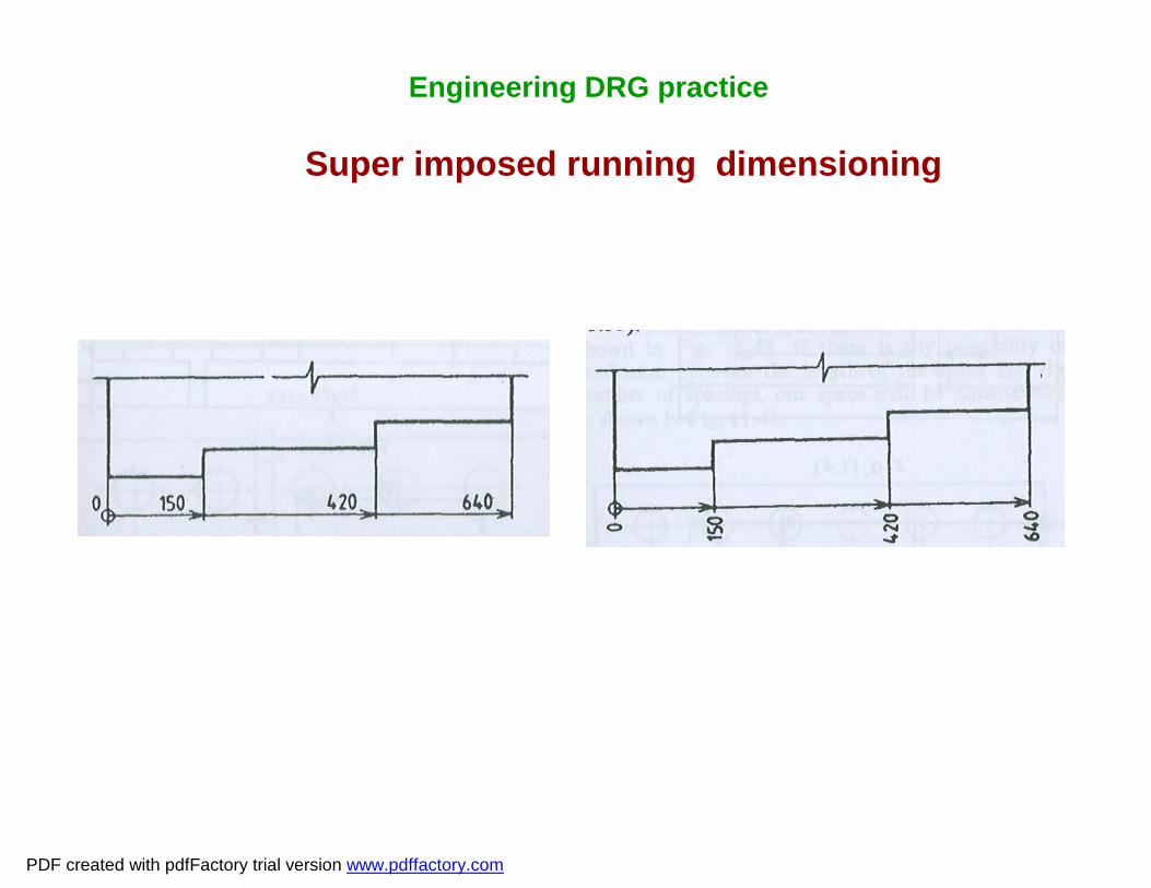
Super imposed running dimensioning
Engineering DRG practice
PDF created with pdfFactory trial version www.pdffactory.com

Equidistance feature
Engineering DRG practice
PDF created with pdfFactory trial version www.pdffactory.com
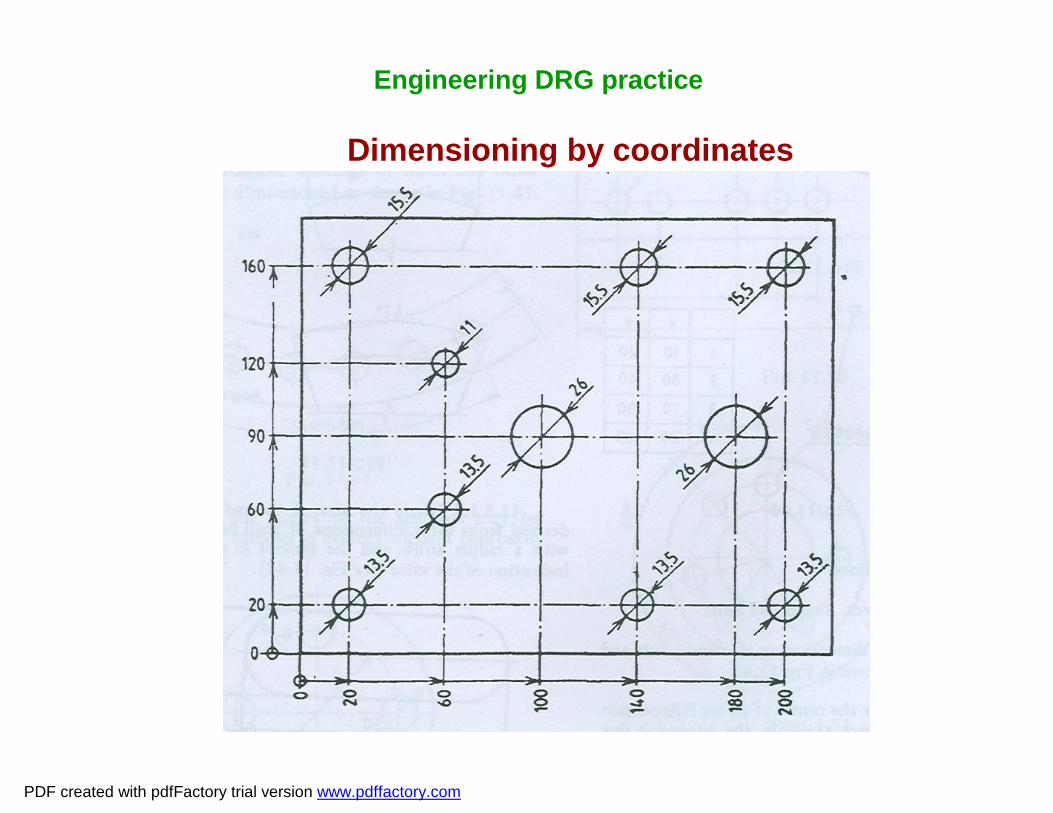
Dimensioning by coordinates
Engineering DRG practice
PDF created with pdfFactory trial version www.pdffactory.com
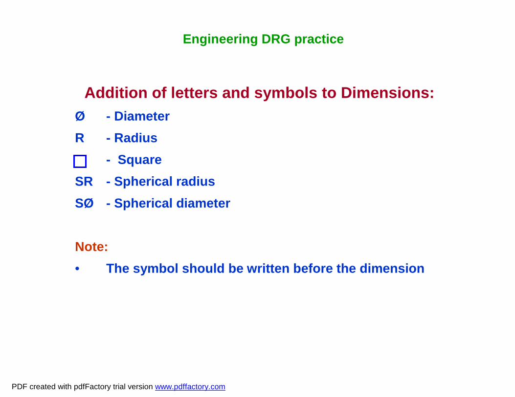
Addition of letters and symbols to Dimensions:Ø - DiameterR - Radius
- SquareSR - Spherical radiusSØ - Spherical diameter
Note:• The symbol should be written before the dimension
Engineering DRG practice
PDF created with pdfFactory trial version www.pdffactory.com

Limits, Fits and TolerancesLimits:• Limits are the two extreme permissible sizes between which
the actual size is contained.eg:30±0.02
Fit:• The relation between two parts where one is inserted into the
other with a certain degree of tightness or looseness is known as fit.
Engineering DRG practice
PDF created with pdfFactory trial version www.pdffactory.com

Types of fit:• Clearance fit• Interference fit• Transition fit
Clearance fit:• A positive allowance between the largest possible shaft and
the smallest possible hole.
Clearance fit- sub classifications:1. Slide fit2. Easy slide fit 3. Running fit4. Slack running fit5. Loose running fit
Engineering DRG practice
PDF created with pdfFactory trial version www.pdffactory.com

Interference fit:• A negative allowance or interference between the largest
possible hole and the smallest possible shaft.
Interference fit-sub classifications:1. Shrink or force fit2. Heavy drive fit3. Light drive fit
Transition fit• They cover cases between the first two classes
Condition:LL on shaft < LL on holeHL on shaft > LL on hole
Engineering DRG practice
PDF created with pdfFactory trial version www.pdffactory.com

Engineering DRG practice
Basic size, deviations and tolerances
PDF created with pdfFactory trial version www.pdffactory.com

Transition fit sub-classification:1. Force fit2. Tight fit3. Wringing fitTolerances:• Tolerance is the difference between high limit and low limit
of size.Types of tolerances:1. Bilateral tolerance:• If tolerance is applied on both sides of the basic size, then it
is called bilateral tolerance. eg:30±0.02
Tolerance = High limit - Low limit = 30.02 – 29.98 = 0.04
Engineering DRG practice
PDF created with pdfFactory trial version www.pdffactory.com

2. Unilateral tolerance:If tolerance is applied on one side of the basic size, then it is called Unilateral tolerance. eg:30- 0.02
Tolerance = High limit - Low limit = 30.0 – 29.98= 0.02
Allowances:• An intentional difference between the hole DIM and shaft
DIM for any type of fit is called the allowance.Deviation:• The algebraic difference between actual size and the basic
size of a component.
Engineering DRG practice
PDF created with pdfFactory trial version www.pdffactory.com

Engineering DRG practice
Disposition of tolerance zones for the three class of fit
PDF created with pdfFactory trial version www.pdffactory.com
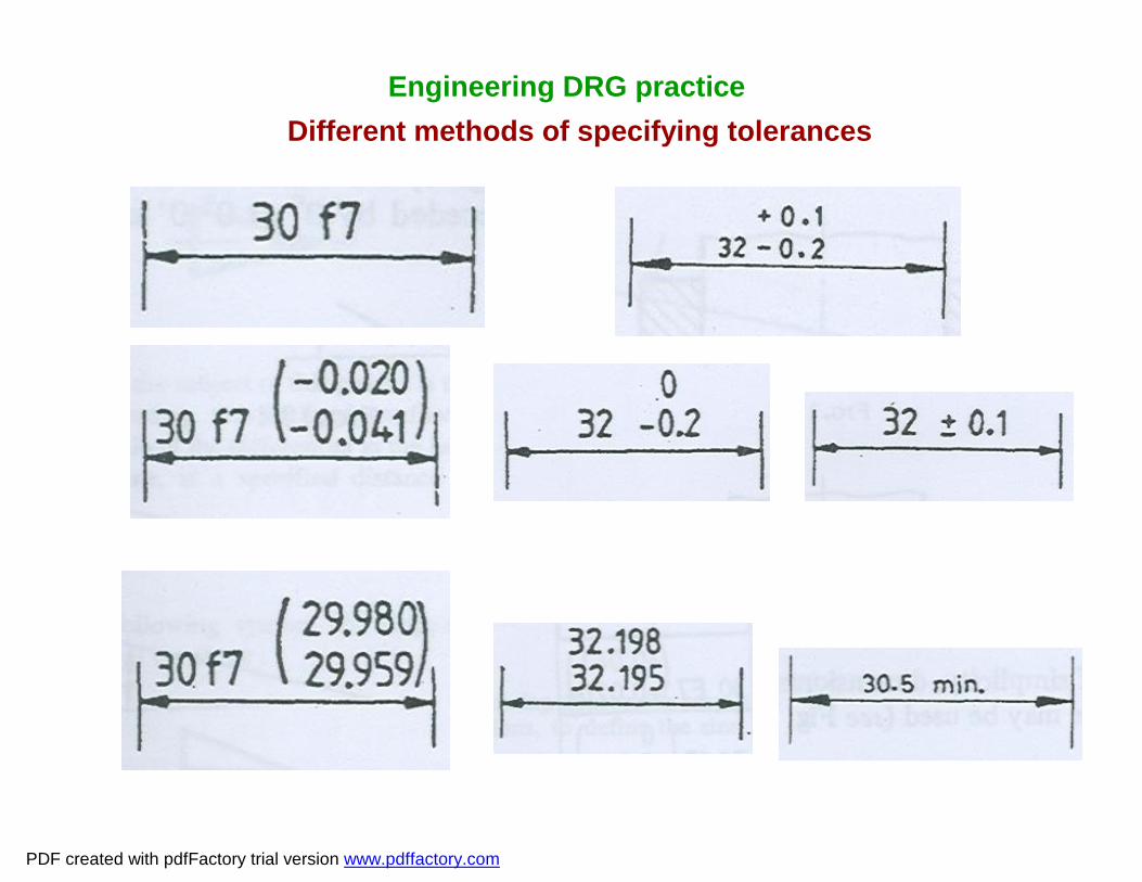
Engineering DRG practiceDifferent methods of specifying tolerances
PDF created with pdfFactory trial version www.pdffactory.com

Engineering DRG practice
Different methods of specifying Fits on assembled parts
-0.020-0.041
PDF created with pdfFactory trial version www.pdffactory.com
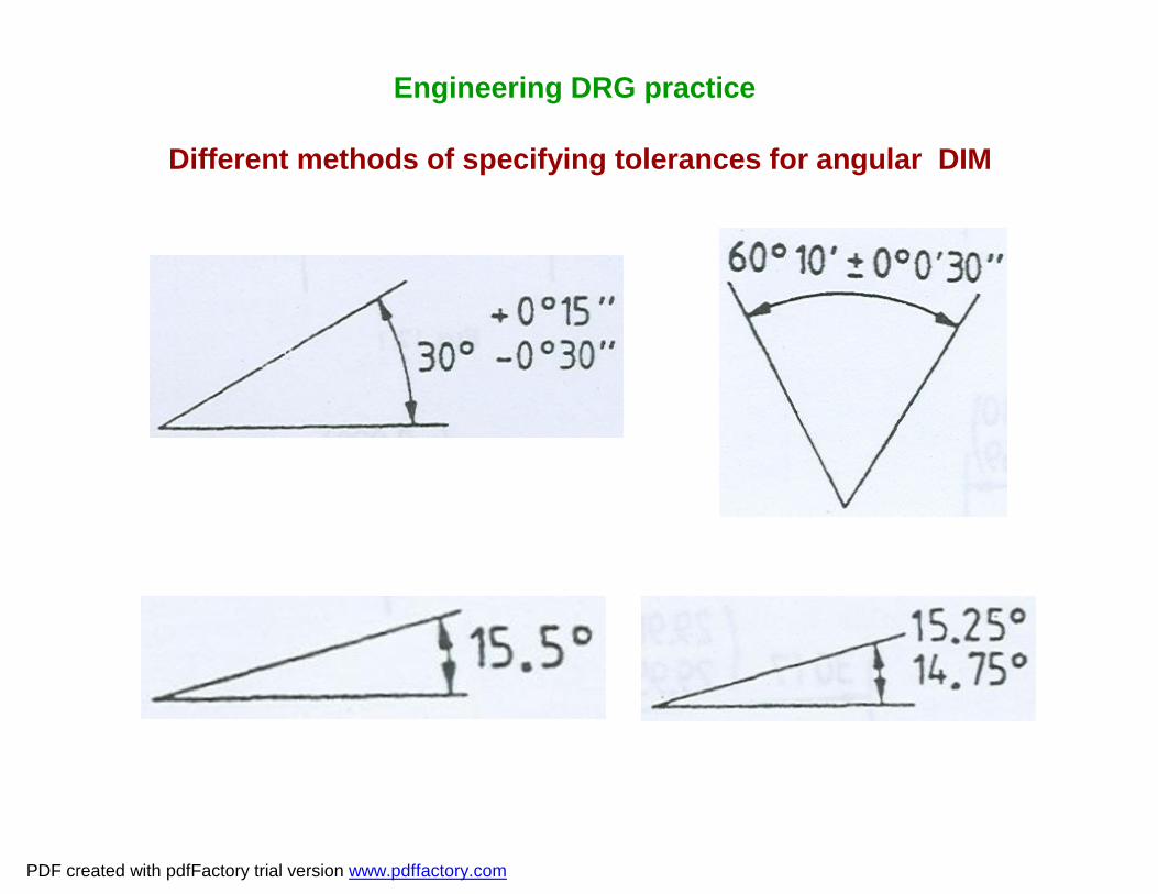
Engineering DRG practice
Different methods of specifying tolerances for angular DIM
PDF created with pdfFactory trial version www.pdffactory.com

Types of deviation:• Upper deviation:• The algebraic difference between max. limit and the basic
size2. Lower deviation:• The algebraic difference between min. limit and the basic
sizeFundamental deviation:• It is one of the two deviations which is conveniently chosen
to define the position of the tolerance zone in relation to zeroline
Engineering DRG practice
PDF created with pdfFactory trial version www.pdffactory.com

Hole basis system:• In this system, the hole DIM (whose lower deviation is zero &
Symbol H) is kept constant and different types of fit are obtained by varying the size of the shaft.
• Most widely used
Shaft basis system:• In this system the shaft DIM (whose upper deviation is zero
& Symbol h) is kept constant and different types of fit are obtained by varying the size of the hole.
Engineering DRG practice
PDF created with pdfFactory trial version www.pdffactory.com

Engineering DRG practice
The Shaft basis and the Hole basis system
PDF created with pdfFactory trial version www.pdffactory.com

Engineering DRG practiceTolerance bands for different shafts & holes
PDF created with pdfFactory trial version www.pdffactory.com

Engineering DRG practice
Selection of tolerance zones
PDF created with pdfFactory trial version www.pdffactory.com

Some of the select ISO fits- Hole basis:Clearance fit:H6g5H7g6 precision runningH8g7
H6f6H7f7 close runningH8f8
H8e7H8e8 normal runningH9e9
Engineering DRG practice
PDF created with pdfFactory trial version www.pdffactory.com

Some of the select ISO fits- Hole basis:Clearance fit:H8d8H8d9 loose runningH9d9
H8c8 H8b8 H9c9H11c11 slack running or positional fitH11c9 H11b9
Engineering DRG practice
PDF created with pdfFactory trial version www.pdffactory.com

Some of the select ISO fits- Hole basis: contd…
Location and assembly fit:
H6h5 Precision locationH6h6
H7h6 Close location H7h7
H8h7 Normal location H8h8
Engineering DRG practice
PDF created with pdfFactory trial version www.pdffactory.com

Some of the select ISO fits- Hole basis: Location and assembly fit: contd…
H9h8 Loose location H9h9
H11h9 Slack AssyH11h11
H8h9 Positional fit
Engineering DRG practice
PDF created with pdfFactory trial version www.pdffactory.com

Some of the selected ISO fits- Hole basis: Transition and Interference fit:H6j5H7j6 Clearance transition H8j7
H6k5 True transition H7k6H8k7
H6m5H7m6 Interference transitionH8m7H6p5 Press fitH7p6
Engineering DRG practice
PDF created with pdfFactory trial version www.pdffactory.com

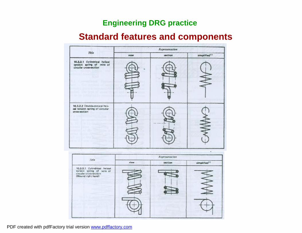
Standard features and components
Engineering DRG practice
PDF created with pdfFactory trial version www.pdffactory.com

Engineering DRG practice
Standard features and components
PDF created with pdfFactory trial version www.pdffactory.com
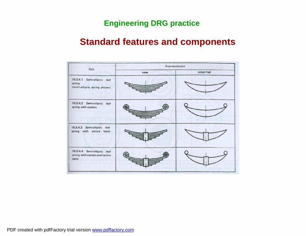
Engineering DRG practice
Standard features and components
PDF created with pdfFactory trial version www.pdffactory.com
Engineering DRG practice
Standard features and components
PDF created with pdfFactory trial version www.pdffactory.com

Engineering DRG practice
Standard features and components
PDF created with pdfFactory trial version www.pdffactory.com

Engineering DRG practice
Standard features and components
PDF created with pdfFactory trial version www.pdffactory.com

Engineering DRG practice
Welding Symbols
PDF created with pdfFactory trial version www.pdffactory.com

Engineering DRG practice
Welding Symbols
PDF created with pdfFactory trial version www.pdffactory.com

Engineering DRG practice
Welding Symbols
PDF created with pdfFactory trial version www.pdffactory.com

Engineering DRG practice
Welding Symbols
PDF created with pdfFactory trial version www.pdffactory.com

Engineering DRG practice
Standard Abbreviations
PDF created with pdfFactory trial version www.pdffactory.com

Standard AbbreviationsEngineering DRG practice
AhAmpere-hourAAmpere
BRGBearing
acAlternating current
ARRGTArrangementAPPROXApproximate
A/CAcross cornersA/FAcross flats
ALTAlteration
HBBrinell hardnessbhpBrake horse power
AUXASSY
APPD
Abbreviation
AuxiliaryAssembly
Approved
Term
PDF created with pdfFactory trial version www.pdffactory.com

Engineering DRG practice
CONTDContinued
CONNConnected
OceCircumference
CH HDCheese head
CPCircular Pitch
CHKDChecked
CHMEDChamfered
C/CCentre to centre
CGCentre of gravity
CLCentre line
CRSCentres
CICast iron
AbbreviationTerm
Standard Abbreviations
PDF created with pdfFactory trial version www.pdffactory.com

Engineering DRG practice
CYLCylinder / Cylindrical
DRGDrawing
dcDirect current
mm3Cubic millimetre
DIMDimension
CSK HDCountersunk head
DPDiametral Pitch
DIADiameter (in a note)
KDegree Kelvin
0CDegree Celsius
m3Cubic Metrecm3Cubic centimeter
CSKCountersunkC’BORECONSTAbbreviation
Counter boreConstant
TermStandard Abbreviations
PDF created with pdfFactory trial version www.pdffactory.com

Engineering DRG practice
HYDHydraulic
HDHead
etcet cetera
EEast
hHourhpHorse PowerHORZHorizontalHEXHexagon / Hexagonal
GLGround levelgGramGEN
FIG.
EXT
Abbreviation
General
Figure
External
TermStandard Abbreviations
PDF created with pdfFactory trial version www.pdffactory.com

Engineering DRG practice
kVAKilovolt-ampere
JJoule
kmKliometrekm/hKilometre per hour
klKilolitre
INSULInsulation
ISIndian Standard
kgfKilogram force
kWhKilowatt hourkWKilowattkVKilovolt
kgKilogram
ihpINTIDINSP
Abbreviation
Indicated Horse PowerInternalInside Diameter Inspection / Inspected
TermStandard Abbreviations
PDF created with pdfFactory trial version www.pdffactory.com

Engineering DRG practice
µmMicrometre
mMetre
lLitreLHLeft Hand
l/minLitres per minute
MATLMaterial
mmMillimetre
MECHMechanicalm/sMetre per second
MWMegawattMPaMega PascalMNmax.MFGM/C
Abbreviation
Mega NewtonMaximumManufacture / ManufacturingMachine / Machinery
TermStandard Abbreviations
PDF created with pdfFactory trial version www.pdffactory.com
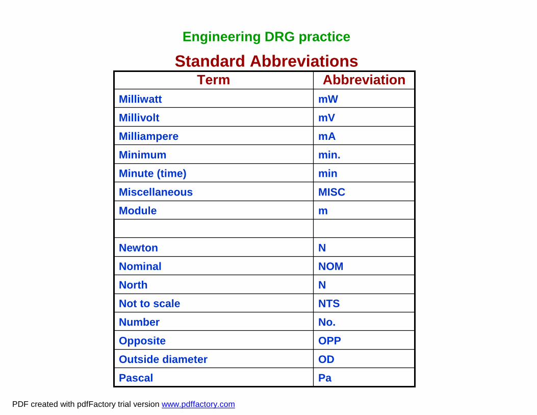
Engineering DRG practice
NTSNot to scaleNNorth
minMinute (time)
mWMilliwattmVMillivolt
PaPascalODOutside diameterOPPOppositeNo.Number
NOMNominalNNewton
mMISC
min.mA
Abbreviation
ModuleMiscellaneous
MinimumMilliampere
TermStandard Abbreviations
PDF created with pdfFactory trial version www.pdffactory.com

Engineering DRG practice
PCDPitch Circle DiameterPCPitch Circle
sSecond (time)HRCRockwell hardness”C” scaleHRBRockwell hardness”B” scaleHRARockwell hardness”A” scaleRHRight HandrpmRevolution per minuteREQDRequiredREFReferenceRradQTYP
Abbreviation
RadiusRadianQuantityPressure
Term
Standard Abbreviations
PDF created with pdfFactory trial version www.pdffactory.com

Engineering DRG practice
SYMSymmetrical
m2Square metre
mm2Square millimetre
cm2Square centimetreSQSquare
StStokes
SFSpot faceSTDStandardSPHERE
SPECSSl No.
Abbreviation
Spherical
SpecificationSouthSerial number
Term
Standard Abbreviations
PDF created with pdfFactory trial version www.pdffactory.com

Engineering DRG practice
THKThick
WWatt
HVVickers hardness
vVelocity
volVolumeVVolt
TOLTolerance
TrTrapezoidaltTonnet
TEMP
THRUTHD
Abbreviation
Time
Temperature
Through (in a note)Thread (in a note)
Term
Standard Abbreviations
PDF created with pdfFactory trial version www.pdffactory.com

Engineering DRG practice
WRTWith respect toW
WT/m
WTWh
Abbreviation
West
Weight per metre
WeightWatt hour
Term
Standard Abbreviations
PDF created with pdfFactory trial version www.pdffactory.com

Engineering DRG practice
Materials, Heat treatment & Protective coatings
PDF created with pdfFactory trial version www.pdffactory.com

Engineering DRG practice
Materials
Some typical materials:1. Wrought steels:• IS:5517, IS: 2062, IS:4454• Rolled homogeneous Armour plates2. Cast steels:• IS:1030, IS:3444, IS:2856, IS:30383. Cast light alloy:• IS:617
PDF created with pdfFactory trial version www.pdffactory.com

Engineering DRG practice
Heat treatmentTypical notes:• Harden and temper to 32-35 HRC• Case carburise and harden gear teeth / surfaces marked
thus # to 60 - 65 HRC• Stress relieve after welding prior to machining
PDF created with pdfFactory trial version www.pdffactory.com

Engineering DRG practiceProtective Coatings
• IS:3618: 1966 – Phosphate treatment of iron and steel for protection against corrosion.
Typical note: To be phosphate treated to IS:3618, Class ‘B’Note : Class ‘B’ indicates – Medium weight 4.3 g/m2
• IS:1573:1970 - Electroplated coating on Zinc and on iron and steel
Typical note: To be Zinc plated to IS:1573, Fe Zn 40Note : Meaning of Fe Zn 40
40 – min. local thickness in micronsZn - Zinc coatingFe – Basic metal (iron or steel)
• IS: 1572-1968 – Cadmium coating on iron and steel Typical note: To be Cadmium coated to IS:1572:1970, Cd8Note : Meaning of Cd8 – min. local thick 8 microns and Average thick
12microns
PDF created with pdfFactory trial version www.pdffactory.com

Engineering DRG practice
Design office management
PDF created with pdfFactory trial version www.pdffactory.com

Engineering DRG practice
1.Purpose of design office:The creation, storage, retrieval and dissemination of
engineering information, usually pertaining to specific products/ processes.2. Relationship between Design and Drawing:
Design is the initial creative process whereby the product as envisaged is given shape, size and properties / performance on paper before physical realisation of the end product.3. Engineering DRG:
The document resulting from the design process which gives all relevant information for the manufacture / procurement of the product.
Design office management
PDF created with pdfFactory trial version www.pdffactory.com

Engineering DRG practice
Design office management
KNOWLEDGE
Physical Science
ENGG Technology
Other
SKILLS
Measurement
Graphical expression
Simulation
Experimentation
Mathematics
Management
Interactive ability
Communication
Decision making
SKILLS APPROACH
Interest
Objectivity
Open -mindedness
Creative Imagination
Product design
PDF created with pdfFactory trial version www.pdffactory.com

Engineering DRG practice
Design office management
DRG Creation:1. Conventional drafting.• Low capital outlay• Quality and accuracy of the drawings depend upon the
individual skill and care of the human element• It is easier for the designers to visualise the product size
and configurational aspects• The DIM are not inherently related to what is drawn; hence
the probability of errors is more• Redrawing and corrections are tedious • Physical handling is more involved• More storage space is required
PDF created with pdfFactory trial version www.pdffactory.com

Engineering DRG practice
Design office management
DRG Creation:2. Computer Aided drafting.• High capital outlay• High Quality and accuracy• It is difficult for the designers to visualise the product size
in 2D mode • The DIM are inherently related to what is drawn; hence the
probability of errors is less• Redrawing, scaling and alterations are easier • Digital storage and handling are easier and more
acceptable
PDF created with pdfFactory trial version www.pdffactory.com

Engineering DRG practiceDesign office management
Other aspects:1. DRG storage and retrieval2. DRG reproduction3. DRG numbering system4. DRG Amendments
PDF created with pdfFactory trial version www.pdffactory.com

Engineering DRG practice
Exercises
• DRG sheet print folding and filing
• Missing views in Orthographic DRG
• Dimensioning
• Dimensional tolerancing for specific fits
• Geometric tolerancing
• Specifying surface finish, heat treatment, protective coating,
hardness, welding, symbolic representation, materials etc.
• DRG Numbering, item No., Qty, parts list
• DRG Amendments, revision etc.
PDF created with pdfFactory trial version www.pdffactory.com

Engineering DRG practice
Exercise
PDF created with pdfFactory trial version www.pdffactory.com
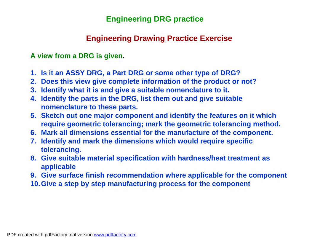
Engineering DRG practice
Engineering Drawing Practice Exercise
A view from a DRG is given.
1. Is it an ASSY DRG, a Part DRG or some other type of DRG?2. Does this view give complete information of the product or not?3. Identify what it is and give a suitable nomenclature to it.4. Identify the parts in the DRG, list them out and give suitable
nomenclature to these parts.5. Sketch out one major component and identify the features on it which
require geometric tolerancing; mark the geometric tolerancing method.6. Mark all dimensions essential for the manufacture of the component.7. Identify and mark the dimensions which would require specific
tolerancing.8. Give suitable material specification with hardness/heat treatment as
applicable 9. Give surface finish recommendation where applicable for the component10.Give a step by step manufacturing process for the component
PDF created with pdfFactory trial version www.pdffactory.com

Engineering DRG practice
Engineering Drawing Practice Exercise
PDF created with pdfFactory trial version www.pdffactory.com

Engineering DRG practice
Engineering Drawing Practice Exercise
A shaft and a hole are shown in the DRG.CASE I:Dimension a = 30 mm; both materials are steel.1. Give tolerances to obtain a precision sliding fit with interchangeability.2. What is the maximum clearance in the above fit?3. What is the minimum clearance in the above fit?4. Give tolerances for a precision location fit with interchangeability.5. What is the maximum clearance in the fit mentioned in sl.No.4?6. What is the minimum clearance in the fit mentioned in sl.No.4?7. What is the maximum interference in the fit mentioned in sl.No.4?8. What is the minimum interference in the fit mentioned in sl.No.4?
PDF created with pdfFactory trial version www.pdffactory.com

Engineering DRG practice
Engineering Drawing Practice Exercise
A shaft and a hole are shown in the DRG.CASE II:Dimension a = 70 mm; both materials are steel.1. Give tolerances to obtain a precision sliding fit with interchangeability.2. What is the maximum clearance in the above fit?3. What is the minimum clearance in the above fit?
PDF created with pdfFactory trial version www.pdffactory.com

Engineering DRG practice
Engineering Drawing Practice Exercise
A shaft and a hole are shown in the DRG.CASE III:
Dimension a = 30 mm; Bore material Al. alloy and shaft steel.1. Give tolerances to obtain a precision location fit with interchangeability.2. What is the maximum clearance in the above fit?3. What is the minimum clearance in the above fit?4. What is the maximum interference in the above fit?5. What is the minimum interference in the above fit?
PDF created with pdfFactory trial version www.pdffactory.com